

Page 1

1
Note
Read this guide carefully before using this product.
Always keep this guide at hand so that you can see it when necessary.
N8405-024F
2008 Apr. 2nd Edition
Blade Enclosure (SIGMABLADE-H)
User's Guide
855-900677-A
PN# 456-01750-000
Page 2

2
This product has been tested and found to comply with the limits for a Class A digital device,
pursuant to Part 15 of the FCC rules. These limits are designed to provide reasonable protection
against harmful interface when the device is operated in a commercial environment. This
device generates, uses and can radiate radio frequency energy and if not installed and used in
accordance with the instruction manual, may cause harmful interference to radio
communications. Operation of this device in a residential area is likely to cause harmful
interface in which case the user will be required to correct the interference at his own expense.
Warning
To meet FCC rule, use the following rack with front and rear doors in place and closed.
Never operate without doors and under doors are opened.
APC “NetShelter® VX 42U Enclosure w/Sides Black” [AR2100BLK]
Warning
This is Class A product. In a domestic environment this product may cause radio interference in
which case the user may be required to take adequate measures.
FCC COMPLIANCE
CE and C-Tick STATEMENTS
Trademarks
NEC EXPRESSBUILDER and NEC ESMPRO, NEC DianaScope, EXPRESSSCOPE, NEC ExpressCluster,
SigmaSystemCenter, WebSAM, DeploymentManager and VALMOware Network Manager are trademarks or registered
trademarks of NEC Corporation.
Microsoft, Windows, Windows Server, Internet Explorer, .NET Framework are trademarks or registered trademarks of Microsoft
Corporation in the United States and other countries.
Intel and Pentium are registered trademarks of Intel Corporation.
HP-UX is a registered trade mark of Hewlett-Packard Company.
Wake on LAN is a trade mark or registered trademark of International Business Machines Corporation.
Java and all logos related to Java are trademarks or registered trademarks of Sun Microsystems, Inc.
Tomcat is a trademark or registered trademark of Apache Software Foundation.
Linux is a trademark or registered trademark of LinusTorvalds in the United States and other countries.
All other product, brand or trade names mentioned in this publication are the trademarks or registered trademarks of their
respective companies.
Microsoft® Windows ServerTM 2003, Standard Edition, Microsoft® Windows ServerTM 2003, Enterprise Edition, Microsoft®
Windows ServerTM 2003, Datacenter Edition, Windows ServerTM 2003, Standard x64 Edition, Windows ServerTM 2003, and
Enterprise x64 Edition are called Windows Server 2003 in short.
Microsoft® Windows ServerTM 2003 R2, Standard Edition, Microsoft® Windows ServerTM 2003 R2, Enterprise Edition,
Microsoft® Windows ServerTM 2003 R2, Datacenter Edition, Microsoft® Windows ServerTM 2003 R2, Standard x64 Edition,
Microsoft® Windows ServerTM 2003 R2, Enterprise x64 Edition, Microsoft® Windows ServerTM 2003 R2, and Datacenter x64
Edition are called Windows Server 2003 R2 in short.
Microsoft® Windows® 2000 Server operating system, Microsoft® Windows® 2000 Advanced Server operating system,
Microsoft® Windows® 2000 Professional operating system are called Windows 2000 in shot.
Microsoft® Internet Explorer is called Internet Explorer for short.
Java Runtime Environment is called JRE for short.
Names used with sample applications are all fictitious. They are unrelated to any existing product names, names of organizations,
or individual names.
Notes
(1) No part of this manual may be reproduced in any form without prior written permission of NEC Corporation
(2) The contents of this manual are subject to change without prior notice.
(3) The contents of this manual shall not be copied or altered without prior written permission of NEC Corporation
(4) All efforts have been made to ensure the accuracy of all information in this manual. If you find any part unclear,
incorrect, or omitted in this manual, contact the sales representative where you purchased this product.
(5) NEC assumes no liability arising from the use of this product, nor any liability for incidental or consequential
damage arising from the use of this manual regardless of (4) above.
Page 3

3
Notes for safe handling
Indicates there is a risk of death or serious injury.
Indicates there is a risk of burn or injury.
Attention
This symbol indicates the presence of a hazard.
An image in the symbol illustrates the hazard
type.
(Example)
(Electric
shock)
Prohibited
actions
This symbol indicates prohibited actions. An
image in the symbol illustrates a particular
prohibited action.
(Example)
(Do not
disassemble)
Mandatory
actions
This symbol indicates mandatory actions. An
image in the symbol illustrates a mandatory action
to avoid a particular hazard.
(Example)
(Unplug)
Do not plug the cord into a nonconforming outlet.
Use wall outlets with specified voltage and power type. Failure to observe this
caution could result in a fire or current leakage.
Note
Keep this User's Guide handy for quick reference when necessary.
Make sure to read "Notes for safe handling." When you relocate the product, make sure to take this
guide with the product.
CAUTION
CAUTION
WARNING
This section provides information for using the product safely.
SAFETY INIDICATIONS
To use this product safely, follow the instructions in this User's Guide.
This guide explains components that pose a danger, types of dangers caused by failing to follow the
instructions, and actions taken to prevent them; such components are labeled warning.
This guide and warning labels use "WARNING" and "CAUTION" to indicate a danger depending
on the degree. These terms are defined as follows:
This guide uses the following three types of symbols to give indications and precautions against a
danger. They are defined as follows:
Example of indications in this guide
Symbol indicating attention Description of a danger Term indicating degree of danger
Page 4

4
Indicates the risk of electric
shock.
Indicates the risk of explosion.
Indicates the risk of injury due to
a caught hand or finger.
Indicates the risk of smoke emission
or fire outbreak.
Indicates the risk of burn due to
hot surface.
Indicates the risk of injury due to
rotation of objects.
Indicates a general notice or
warning that cannot be
specifically identified.
Indicates prohibition of
disassembling or reconfiguring
the unit.
Avoid using water or liquid nearby.
If it spills on the card, there is a risk
of electric shock or fire.
Do not touch with wet hands.
There is a risk of electric shock.
Indicates notice of general
prohibition.
Indicates instructions to pull
power plug from outlet and to
turn off main circuit breaker.
Indicates required general actions for
operators.
Symbols and their descriptions used in this User's Guide
and warning labels are as follows:
Attention
Prohibited actions
Mandatory actions
Page 5

5
General precautions
Do not use this product for services where critical high availability may
directly affect human lives.
This product is not intended to be used with or control facilities or devices
concerning human lives, including medical devices, nuclear facilities and
devices, aeronautics and space devices, transportation facilities and devices; and
facilities and devices requiring high reliability. NEC assumes no liability for any
accident resulting in personal injury, death, or property damage if this product
has been used in the above conditions.
Do not disassemble, repair, or alter this product.
Never disassemble, repair, or alter this product on any occasion other than
described in this manual, otherwise it may cause an electric shock or fire as well
as malfunctions of this product.
Do not use this product if any smoke, odor, or noise is present.
If smoke, odor, or noise is present, immediately turn off the POWER of the CPU
blades and disconnect the power plug from the outlet, then contact your sales
representative. Using this product in such conditions may cause a fire.
Do not insert a wire or metal object.
Do not insert a wire or metal objects into a vent or a slot. There is a risk of
electric shock.
Do not install or remove multiple CPU blades at the same time.
Install or remove CPU blades one at a time. If you install or remove two or more
CPU blades, or install a CPU blade while the cover of another slot is removed, there
is a risk of electric shock.
WARNING
Precautions for safety
Observe the precautions for safety described in this section. The blade enclosure
(SIGMABLADE-H) on which this card is installed has power units. Carefully use them to avoid
any electric shock.
.
Page 6

6
Prevent water or foreign objects from the product.
Do not allow water or foreign objects (e.g., pins or paper clips) to enter into the
product. There is a risk of fire, electric shock, and breakdown. When such things
accidentally enter the server, immediately turn off the power and unplug the cords.
Contact your sales representative instead of trying to disassemble it yourself.
Connect firmly.
Connect interface cables, option boards, and modules to the CPU blade securely.
Install the card securely on the blade enclosure. Failure to connect or install securely
may result in poor contact that can cause a fire or smoke.
Do not use any unauthorized interface cable.
Use only the interface cable that comes with this product. Use of an unauthorized
interface cable may cause a fire when the electric current exceeds the rated flow.
Also, observe the following to prevent an electric shock or fire caused by a
damaged cord.
Do not touch the fan blades when moving.
Keep your hands or hair away from the cooling fans on the rear of the blade
enclosure; otherwise they may get caught in the fan, resulting in injury. Do not
insert an object in the fan. Doing so may cause personal injury as well as the
malfunction of the device.
Do not touch the heated objects.
Immediately after the blade enclosure is powered off, components in the blade
enclosure and CPU blades are very hot. Leave the blade enclosure until those
components fully cool down before installing/removing any component. In
addition, hot air is exhausted from the power supply fan. Keep your face and
hands away from the air outlet.
Avoid contact with the blade enclosure during thunderstorms.
Disconnect the power plug from the outlet when a thunderstorm is approaching.
If it starts thundering before you disconnect the power plug, do not touch any
part of the blade enclosure including the cables, otherwise it may cause a fire or
an electric shock.
Keep animals away.
Keep animals away from the product. Animal waste or hair may get inside the
product, causing a fire or electric shock.
Do not use a cellular phone or pager near the product.
Turn off your cellular phone or pager when you use the product. Their radio waves
may cause the server to malfunction.
CAUTION
Page 7

7
Power Supply and Power Cord
Do not hold the power plug with wet hands.
Do not disconnect/connect the plug while your hands are wet, otherwise it may cause
an electric shock.
Do not connect the protective earthing conductor to a gas pipe.
Never connect the protective earthing conductor to a gas pipe; otherwise it may
cause a gas explosion.
Plug into a proper power source.
Use a proper wall outlet. Use of an improper power source may cause a fire or a
leak. Do not install the blade enclosure where you need an extension cord.
Use of a cord that does not meet the power specifications of the blade enclosure may
heat up the cord and cause a fire. The maximum power consumption per power unit
is 3000 VA. Note the capacity of a power unit when it is connected to CPU blades.
Do not connect many loads on one electrical outlet.
The electric current exceeding the rated flow overheats the outlet, which may cause a
fire.
Place the power supply tap in a place where it is noticeable and easy to
access.
Place the power supply tap in a place where it is noticeable and easy to access so that
power can be shut off in emergency.
Insert the power plug completely.
Heat generation resulting from a halfway inserted power plug (imperfect contact)
may cause a fire. Heat will also be generated if condensation is formed on dusty
blades of the halfway inserted plug, increasing the possibility of fire.
Use the proper power cord only
Use of an improper power cord may cause a fire when the electric current exceeds
the rated flow. Also, observe the following to prevent an electric shock or fire caused
by a damaged cord.
Do not stretch the cord harness.
Do not pinch the power cord.
Do not bend the power cord.
Keep chemicals away from the power cord.
Do not twist the power cord.
Do not place any object on the power cord.
Do not bundle power cords.
Do not alter, modify, or repair the power cord.
Do not secure the power cord with staples or equivalents.
Do not use any damaged power cord. (Replace a damaged power cord with a new
one of the same specifications. Ask your sales representative for detailed information
on power code.)
CAUTION
WARNING
Page 8

8
Installation and handling of the rack
Install the server rack ONLY in a specified or designated environment
Do not install the rack on which the blade enclosure is installed in an unsuitable
place.
Other devices installed on the blade enclosure or the rack may be affected, a fire may
occur, or the rack may fall, causing injury. For details about installation environment
and quake-resistant engineering, see the manual attached to the rack or contact your
maintenance service agent.
Do not install the blade enclosure in a non-conforming rack
Install the blade enclosure in a 19-inch rack conforming to the EIA standard. Do not
install the blade enclosure in a nonconforming rack, otherwise devices on the blade
enclosure may not function properly, and there is a risk of injuries or damage to
physical assets. For more information about suitable racks on which the blade
enclosure can be installed, contact your sales representative.
Set up noise treatment
The blade enclosure may emit loud noises from fans when it is operating. It is
recommended to install the blade enclosure in a dedicated room that is distant from
people. Arrange acoustic noise treatment such as partitions if you work near the
operating blade enclosure for a long period of time.
WARNING
Page 9

9
Do not carry or install alone.
Carry or install a rack with two or more people. If the rack is carried by one person,
the rack may fall and cause injury or damage to physical assets. A tall rack such as a
44 U rack, in particular, is unstable if it is not fixed by stabilizers. Make sure to
support the rack with two or more people to carry and/or fix it.
Do not install the rack in such a manner that weight is imposed on a single
spot.
Avoid concentration of weight loads of the rack and units installed on a single spot.
Use stabilizers or connect two or more racks to balance loads. If not, the rack may
fall over and cause injury.
Do not carry or remove parts alone.
Do not work alone to install or remove a part such as a rack door and tray. The part
may fall and be damaged, and there is a risk of injury.
Use a lifter to install a unit.
Use a lifter to install/remove a unit. Otherwise, the unit may fall and be damaged,
and there is a risk of injury especially when you are working with a tall rack (such as
44U rack).
Do not pull out a unit when the rack is not stabilized.
When you pull out a unit from the device, make sure that the rack is fixed (by using
stabilizers or quake-resistant engineering).
Do not pull out two or more units from the rack at the same time.
When two or more units are pulled out from the rack, the rack may fall over. Pull out
one unit at a time.
Do not install excessive wiring beyond the rated power supply.
To prevent burns, fires, and damage to the rack, make sure that the rated load of the
power branch circuit is not exceeded. For more information on installation and
wiring of power-related facilities, contact your electrician or local power company.
CAUTION
Page 10

10
Installation, relocation and storage of the blade enclosure
Separate the blade enclosure into two components and carry each
component with two or more people.
When you want to carry the blade enclosure, separate the rear cage from the module
to make the blade enclosure into two components. With no modules such as a CPU
blade or power unit installed, the enclosure and the rear cage weigh 35.5kg and
31.5kg respectively. Carrying the enclosure or rear cage alone may result in injury.
Carry the enclosure/rear cage with two or more people and firmly hold the handles
of the enclosure or any designated areas. Do not carry the blade enclosure if any
module, such as a CPU blade or power unit, is installed.
Do not install the blade enclosure in a place other than specified.
Do not install the blade enclosure in a place other than specified in this guide. Avoid
the following locations. There is a risk of fire.
● a dusty place
● a humid place located near a boiler, etc.
● a place exposed to direct sunlight
● an unstable place
● a non-restricted access place
Do not use or store the blade enclosure in a corrosive environment.
Avoid using or storing the blade enclosure in an environment which may be exposed
to corrosive gases, such as those including but not limited to: sulfur dioxide,
hydrogen sulfide, nitrogen dioxide, chlorine, ammonia and/or ozone. Avoid
installing the blade enclosure in a dusty environment or a place that may be exposed
to corrosive materials such as sodium chloride and/or sulfur.
Avoid installing the blade enclosure in an environment that may have excessive
metal flakes or conductive particles in the air.
Such environments may cause corrosion or short circuits within the blade enclosure,
resulting in damage to the blade enclosure and possibly a fire hazard.
If there are any concerns regarding the environment at the planned site of installation
or storage, please contact your sales representative.
Do not use the blade enclosure with its covers and fan units removed.
Do not use the blade enclosure with its covers and fans removed. If you use the
blade enclosure without them, the cooling efficiency inside the blade enclosure
degrades, causing malfunction. Also, dust may get in and cause a fire or electric
shock.
Be careful not to hurt your fingers.
Take precautions to avoid pinching your fingers when installing or removing the
blade server on or from the rack.
Be careful not to drop the blade enclosure.
Firmly hold the handles on both sides of the blade enclosure to install or remove it
on the rack. Since brackets on the rack have no mechanism to prevent the device
from falling off, such as a stopper or lock, pulling a device fully out of the rack can
result in the device falling and causing injury. When you install or remove the blade
enclosure, hold the handles on both sides firmly or use a lifter.
WARNING
Page 11

11
Do not impose loads on the blade enclosure while it is pulled out of the rack.
Do not impose loads on the top of the blade enclosure while it is pulled out from the
rack. The frame may be damaged, and you may not be able to install the blade
enclosure on the rack. There is a risk of the blade enclosure falling and causing
injury as well.
Do not cover ventilation openings.
Do not cover ventilation openings of the blade enclosure. Additionally, do not cover
rack openings. If they are covered, the temperature of devices on the blade enclosure
may rise, which may result in a fire.
Do not leave the blade enclosure pulled out of the rack.
Do not operate or perform maintenance with the blade enclosure pulled out. Since
the brackets on the rack have no mechanism to prevent the blade enclosure from
falling off, such as a stopper or lock, pulling the blade enclosure fully out of the rack
can result in the blade enclosure falling and causing injury.
Do not hold any installed module or power unit cover.
When you carry the blade enclosure, do not hold any installed module or power
unit cover. Because they are movable, you might drop the blade enclosure if you
hold them.
Wear a wrist strap to eliminate static electricity.
Installed modules and peripheral devices contain parts that are sensitive to
electrostatic discharge. Wear a wrist strap to eliminate static electricity when you
install or remove the modules or peripheral devices or connect interface cables.
CAUTION
WARNING
Page 12

12
Failure action
Failure action.
When the device fails, shut off the branch circuit breaker of the power distribution
board, unplug the device, and contact your sales maintenance personnel.
Disposal
Lithium battery.
The EM card installed on the blade enclosure uses a lithium battery (the battery is
not replaceable). Contact your NEC sales representative before disposing the EM
card.
Disposal and recycling.
Contact your NEC sales representative before disposal, collection, or recycling of
the device.
CAUTION
WARNING
Page 13

13
Maintenance, cleaning and handling of internal devices
Do not place your hands inside the blade enclosure.
Do not place your hands inside the blade enclosure when you install or remove it.
There is a risk of electric shock. Do not remove the cover attached to the blade
enclosure except when necessary, such as when installing a device.
Installation/removal of a device should be done one by one.
Unplug power cords before maintenance.
Before maintenance, power off all devices installed on the blade enclosure and
unplug the power cords. Even if devices are powered off, there is a risk of electric
shock or fire as well as malfunction when maintenance is performed on the devices
on the blade enclosure with their power cords plugged in.
Disconnect the power plugs from the outlet occasionally and clean the plugs with a
dry cloth. Heat will be generated if condensation is formed on a dusty plug, which
may cause a fire.
During operation
Do not touch when it thunders.
Unplug the power plugs when a thunderstorm is approaching. If it starts to thunder
before you unplug them, do not touch the blade enclosure and cables. There is a risk
of fire or electric shock.
Keep animals away.
Keep animals away from the blade enclosure. Animal waste or hair may get inside
the blade enclosure and cause a fire or electric shock.
Do not pull out the blade enclosure from the rack while it is running.
Do not pull out or remove the blade enclosure from the rack while a device on the
blade enclosure is running. The device may malfunction, and there is a risk of injury.
Do not place any unfixed equipment on the top of the blade enclosure.
To avoid the risk of personal injury or damage to the equipment, never place unfixed
equipment on top of the blade enclosure.
CAUTION
CAUTION
WARNING
Page 14

14
In the European Union
EU-wide legislation as implemented in each Member State requires that used
electrical and electronic products carrying the mark (left) must be disposed of
separately from normal household waste. When disposing of used NEC
products, you should comply with applicable legislation or such terms which
may have been agreed between NEC and your company regarding used
products. The mark on the electrical and electronic products only applies to the
current European Union Member States.
Outside the European Union
If you wish to dispose of used electrical and electronic products outside the
European Union, please contact your local authority and ask for the correct
method of disposal.
Disposing of your used NEC product
Warning labels
Warning labels are placed in certain parts of the blade enclosure so that the user stays alert to
possible risks that may arise.
(Do not remove or damage these labels).
If a label is missing, peeling off, or illegible, contact your sales representative.
For information on symbols in the labels, see "Safety indications" at the top of this document.
Page 15

15
Hint
About maintenance services
Diagnostic and maintenance services by personnel with expertise on maintenance of
the blade enclosure are available.
Handling precautions to use the device correctly
Observe the following precautions to use the blade enclosure device correctly. Failure to observe
the precautions can result in malfunction or mechanical error.
● Blade enclosure
- Use a rack that allows installation of the blade enclosure.
- This product must be installed in a restricted access location.
- Make sure to install or remove parts, such as fan units, correctly when a module is installed
or removed.
- Remove the dust on the exterior and fans located at the front and rear of the blade enclosure
regularly. Regular cleaning prevents various failures from occurring.
- The voltage may drop momentarily due to lightning. It is recommended to use a device such
as an uninterruptible power supply system to prevent this problem.
● Adding optional power supplies and other electronic parts
- These products are made of very static-sensitive parts. Eliminate static electricity before
handling the products. Do not touch plug terminals or parts with your hands. Do not place
the products directly on a desk.
- Do no use any optional devices other than those shipped with the blade enclosure or
specified by NEC. Even if such optional devices can be installed on or connected to the
blade enclosure, they may not work properly or can damage the blade enclosure.
- It is recommended to use genuine NEC products for optional devices. Some optional
devices from other manufacturers are supported in the blade enclosure. However, services
for repairing malfunctions or damage caused by them are provided at your expense, even in
the warranty period.
Page 16

16
Contents
Notes for safety handling ........................................... 3
SAFETY INIDICATIONS .................................. 3
Symbols and their descriptions used in
this User's Guide and warning labels ar
as follows: ........................................................ 4
Precautions for safety ..................................... 5
General precautions ............................. 5
Power Supply and Power Cord .......... 7
Installation and handling of the
rack ....................................................... 8
Installation, relocation and storag
of the blade enclosure ...................... 10
Failure action ..................................... 12
Disposal .............................................. 12
Maintenance, cleaning and
handling of internal devices .............. 13
During operation ................................ 13
Installing a switch module or
pass-through card .............................. 38
Removing a switch module or
pass-through card .............................. 40
Installing a CPU blade .................................. 41
Installable CPU blades ...................... 45
Installing a CPU blade ...................... 46
Removing a CPU blade .................... 48
Assembling a full-height CPU
blade slot cover ................................. 49
Disassembling a full-height CPU
blade slot cover ................................. 53
Installing the EM card ................................... 54
Installing an EM card ........................ 55
Removing an EM card ...................... 56
Installing a fan unit ....................................... 57
Installing a fan unit ........................... 61
Disposing of your used NEC product .......... 14
Warning labels ............................................... 14
Handling precautions to use the device corre
ctly .................................................................. 15
Preface ....................................................................... 21
Overview .................................................................... 21
Accessories ................................................................ 21
Components ............................................................... 22
Front view ...................................................... 22
Rear view ....................................................... 23
Installation .................................................................. 24
Checking components ................................... 24
Installing the blade enclosure on a
rack ................................................................. 24
Check components to install............. 24
Required Tools ................................... 25
Installation Procedure ........................ 25
Removing a fan unit ......................... 62
Installing the front bezel ............................... 63
Filter cleaning..................................... 63
Opening the front bezel .................... 64
Closing the front bezel ...................... 65
Connecting cables ..................................................... 66
Front ............................................................... 66
Local console ..................................... 66
Rear ................................................................ 68
EM serial console .............................. 68
EM console ........................................ 69
LAN console....................................... 70
SFP connector (switch module) ........ 71
SFP connector (pass-through card) . 71
Power connector ................................ 72
Installing cable clamps ...................... 74
Removing a power cord form
Removing the blade enclosure
from the rack ..................................... 29
Installing a switch module or
pass-through card .......................................... 31
Installable switch modules and
pass-through cards ............................ 32
a cable clamp .................................... 77
Emergency power off (EPO) .................................... 79
Power supply tap ............................... 79
Emergency power off switch............. 80
Power unit .................................................................. 81
Installing a power unit ....................... 84
Page 17

17
Removing a power unit ..................... 85
Power unit cover ........................................... 86
Opening the power unit cover .......... 86
Closing the power unit cover ........... 87
Moving the key box .......................... 87
Power on and off ...................................................... 88
Powering on and off the blade
enclosure ........................................................ 88
Powering on and off the blade
enclosure without uninterruptible
power supply system (UPS). ............ 88
Powering on and off the blade
enclosure with uninterruptible
power supply system (UPS). ............ 89
Powering on and off a CPU blade .............. 90
Powering on and off a CPU
blade by its power switch ................. 91
an user (EM card) ........................... 108
Power unit settings (EM card)........ 109
Verifying, backing up, and
restoring the EM card
configuration ..................................... 110
DianaScope settings (EM card) ...... 112
Other settings (CPU blade) ............ 112
Console connection to switch
module/pass-through card ............... 112
Other settings
(switch module/through card) .......... 113
Checking operational status ........................ 114
Blade enclosure ............................... 114
Fan unit ............................................ 114
Power unit ........................................ 115
Updating the enclosure manager
firmware ........................................................ 116
Powering on a CPU blade
by the blade enclosure ..................... 91
Powering on a CPU blade via a
network (switch module/passthrough card)/serial connector
(CPU blade) ....................................... 91
Powering on a CPU blade by the net
work serial (COM) port of an EM card
............................................................ 92
Command-line interface (CLI) (EM card) ................. 97
Connecting a cable to a console ................. 97
Starting a console ......................................... 97
EM serial console (serial
connection) ......................................... 97
EM console (Telnet connection) ....... 98
EM console (SSH connection).......... 98
Initial settings ................................................. 99
Setting EM firmware image ............ 117
Updating the EM firmware .............. 118
Password recovery ...................................... 120
Replacing modules .................................................. 121
Switch module/pass-through card ............... 121
CPU blade ................................................... 122
EM card ....................................................... 123
Fan unit ........................................................ 125
Power unit .................................................... 126
Command input Specifications................................ 131
How to start a CLI ...................................... 131
How to start ..................................... 131
Via the EM serial console .............. 131
Telnet/SSH ....................................... 132
How to enter a command .......................... 133
Basics ............................................... 133
How to enter a command .............. 133
Date and time settings
(EM card) ........................................... 99
User settings (EM card) .................. 100
Rack settings (EM card) ................. 101
Blade enclosure settings
(EM card) ......................................... 101
Network settings (EM card) ............ 103
SNMP settings (EM card) ............... 106
Setting module access right for
User account management ......................... 136
Prompt .............................................. 134
Key operation for entering a
command .......................................... 134
Overview ........................................... 136
Default user...................................... 136
User account .................................... 136
Access right ..................................... 136
Administrator..................................... 136
Page 18

18
CLI additional user .......................... 137
Commands ............................................................... 138
Commands ................................................... 138
Command specification ........................................... 147
Description .................................................... 147
General commands...................................... 148
Clearing the CLI terminal
screen ............................................. 148
Terminating CLI ............................... 148
Displaying a help message............. 148
Displaying command entry
history ............................................. 149
Rack management commands ................... 151
Naming a rack ................................. 151
Displaying a rack name .................. 151
Configuring the unique ID for the rack
.......................................................... 152
62
PING ................................................. 162
Initializing the configuration data
(restoring default values) ............... 163
Enclosure network commands .................... 165
Registering DNS servers ................. 165
Registering addresses to allow IP acc
ess .................................................... 165
Registering SNMP trap
destinations ..................................... 165
Disabling the IP-based access
control function ............................... 166
Disabling the NTP functions ........... 166
Disabling the functions for the
SSH connection ............................... 166
Disabling the SNMP functions ........ 167
Disabling the SNMP TrapAck
Displaying the rack unique ID ........ 152
Displaying connection status of
blade enclosures in the same
rack ................................................. 152
User management commands .................... 154
Adding a user .................................. 154
Assigning a user (for CPU blades/swit
ch modules) ..................................... 154
Assigning a user (for EM card) ..... 155
Disabling a registered user ............. 156
Enabling a disabled user ................ 156
Deleting users .................................. 156
Configuring a password .................. 157
Registering a user contact
information ...................................... 157
Configuring a full user name .......... 158
Configuring a password .................. 159
functions ........................................... 167
Disabling the functions for
Telnet connection ............................. 167
Enabling the IP-based access
control function ................................. 168
Enabling the NTP functions ............ 168
Enabling the functions for the
SSH connection ............................... 168
Enabling the SNMP functions ......... 169
Enabling the SNMP TrapAck
functions ........................................... 169
Enabling the functions for Telnet
connection ........................................ 169
Deleting a registered DNS
server ................................................ 170
Deleting a registered IP
address ............................................. 170
Configuring the access right ........... 159
Displaying registered users ............. 160
Cancelling user assignment
(for CPU blade/switch module) ..... 160
Cancelling user assignment
(for EM card) ................................. 161
System management commands ................ 162
Forcefully disconnecting access to the
EM serial console of switch module 1
Deleting a registered SNMP trap desti
nation ................................................ 170
Configuring IP addresses ................ 171
Configuring a domain name ........... 172
Configuring the default gateway ..... 172
Configuring NTP refresh
intervals ............................................ 172
Configuring the IP address of the pri
mary NTP server ............................. 173
Page 19

19
Configuring the IP address of the sec
ondary NTP server .......................... 173
Configuring the name of an
SNMP community allowing the
Get operation ................................... 173
Configuring the name of an
SNMP community allowing the
Get/Set operation ............................. 174
Configuring the name of an
SNMP community allowing the
Trap operation .................................. 174
Configuring a SNMP contact .......... 175
Configuring an SNMP location ....... 175
Configuring the blade enclosure
location in the rack ......................... 176
Configuring the rack height............. 176
Configuring a SNMP TrapAck
Configuring a time zone ................. 187
Displaying all information about
configuration of the blade
enclosure. ......................................... 187
Displaying the configuration of the CLI
auto termination function ............... 188
Displaying the configuration
information in the CLI command
format ............................................... 188
Displaying date and time ................ 190
Displaying the configuration of the fun
ction to display events .................... 190
Displaying the fan information ........ 190
Displaying the blade enclosure
information ........................................ 193
Displaying the power unit
information ........................................ 194
port number...................................... 177
Displaying the network settings ...... 177
Displaying the SNMP settings ........ 178
SNMP Trap test ............................... 179
Enclosure management command ............. 180
Downloading the configuration
settings (restoration) ........................ 180
Switching active EM ........................ 181
Restarting the EM firmware ............ 182
Configuring the function to
automatically terminate CLI ............. 182
Configuring date and time .............. 182
Configuring the function to display
events ............................................... 183
Configuring the asset tag of the blade
enclosure ........................................ 184
Configuring the machine serial
Displaying the blade enclosure
status ................................................ 196
Displays the blade enclosure
temperature ...................................... 197
Displaying the settings on the
power management function ........... 197
Displaying the EM card /EM
firmware version ............................... 198
Updating EM firmware ..................... 198
Uploading (backing up) the
configuration information .................. 199
Configuring the power saving
mode ................................................. 200
Configuring the maximum
consumable power setting .............. 200
CPU blade management commands.......... 202
Power off CPU blades .................... 202
number of the blade enclosure ...... 184
Configuring the blade enclosure
name ................................................. 185
Configuring the ID LED of the
blade enclosure ................................ 185
Configuring the power control
policy ................................................ 186
Configuring the power redundancy mo
de ...................................................... 186
Power on CPU blades .................... 202
Resetting CPU blades ..................... 203
Controlling the CPU blade ID LED 203
Displaying CPU blade
information ........................................ 203
Listing the CPU blade information in a
list ................................................... 206
Displaying the CPU blade port
map information
Page 20

20
(E-Keying information) ..................... 207
Displaying CPU blade status .......... 207
Configuring the power-on delay
time of the CPU blade ................... 208
Displaying the power-on delay
time of the CPU blade ................... 209
Switch module management
command ...................................................... 211
Connecting to the EM serial
console of the switch module......... 211
Powering off switch modules .......... 213
Powering on switch modules .......... 214
Restarting a switch module ............ 214
Configuring a User Assigned
Name of a switch module .............. 215
Controlling the ID LED of a switch m
odule ................................................. 215
Configuring the language type for EM
cards ............................................... 223
NEC Diana Scope control commands ....... 225
Configuring an NEC DianaScope user
password ........................................ 225
Command name .............................. 225
Argument .......................................... 225
Default value .................................... 225
Supplementary information .............. 225
Displaying an NEC DianaScope
user password .................................. 225
Configuring the DSG status ........................ 226
Default value .................................... 226
Supplementary information .............. 226
Displaying the DSG status ......................... 226
Default value .................................... 227
Supplementary information .............. 227
Displaying information on switch
modules ............................................ 216
Displaying the list of switch
modules ............................................ 216
Displaying the switch module map info
rmation (E-Keying information)........ 217
Displaying the status of switch
modules ............................................ 218
EM management commands ...................... 221
Configuring the unique name of
an EM card ...................................... 221
Controlling the EM card LED ......... 221
Displaying information about the
EM card(s) ....................................... 222
Displaying EM card status .............. 222
Configuration management .......................... 228
Overview ........................................... 228
Backing up configuration ................. 228
Restoring configuration .................... 228
Appendix ....................................................... 229
Time zone ........................................ 229
NEC ESMPRO Manager and Agent ...................... 230
NEC DianaScope Manager, Agent ......................... 231
Troubleshooting ........................................................ 232
Power supply ............................................... 232
Input/output ................................................... 233
Disposal .................................................................... 238
Transfer to third party ............................................. 238
Specification ............................................................. 238
Page 21

21
Preface
Overview
Accessories
Important
Keep the accessories in a safe place. You may need them when an optional device is
added or when the blade enclosure experiences a failure.
Thank you for purchasing the N8405-024F Blade Enclosure (SIGMABLADE-H).
The blade enclosure houses modules such as CPU blades, switch modules, pass-through cards, EM
cards, power units, and fan units to integrate their functions and to allow CPU blades to function as
servers.
Read this guide before you start using the blade enclosure. Also, refer to the "User's Guide" and
"Startup Guide" that come with the SIGMABLADE series.
* This guide can be used for the Slot Cover (Power Unit) N8405-036, Slot Cover (Fan) N8405-037 and the Slot Cover (Switch
Module) N8405-038 as well.
This blade enclosure can integrate a maximum of 16 servers' functions into one blade enclosure by
housing a maximum of 16 CPU blades and 8 pass-through cards or switch modules in a case of 10U
(about 445mm).
N8405-025F Power Unit (option) can be optionally added to the power units that are equipped as
standard. A maximum of six power units can be mounted. The power units support the N+1
redundant mode or the N+N redundant mode. These modes allow for continuous operation even if
one power unit or one power unit system fails. The EM card on the blade enclosure allows for
management of fan units, power units, and CPU blades.
You can use remote KVM of CPU blades by connecting the LAN connecter on an EM card to an
external console (such as a PC).
This product is shipped with various accessories. See the attached components list to check that
everything is included and not damaged. If any accessory is missing or damaged, contact your sales
representative.
Page 22

22
Components
1. Blade slot
From the upper left: Slot 1 – Slot 8
From the lower left: Slot 9 – Slot 16
2. CPU blade slot cover
A plate to cover a slot where no optional CPU
blade is installed
3. Power unit
From the left: Power unit 1 - Power unit 6
4. Power unit slot cover
A cover for a slot where no optional power unit is
installed
5. Power unit ejector
Turn this ejector and pull the handle to remove a
power unit.
6. Power unit lock
Pull this lock forward to release the lock of a
power unit ejector.
7. Power LED (green)
This LED is green when AC power is supplied.
8. Power STATUS LED (amber)
This LED is amber when an error occurs.
9. Key box
A box to fix and lock the power unit cover (can be
slid toward left and right)
10. Separator
A plate to separate the blade slot into the upper and
lower tier (when installing a full-height blade,
remove this plate)
1 3 6 7 8 5 2
4 9 10
The following illustrationdepicts the blade enclosure components. The illustration depicts optional
modules attached to the blade enclosure that are not included as standard.
Front view
(When the front bezel and the power unit cover are opened)
Page 23

23
1. Fan unit
From the upper left: Fan unit 1 – Fan unit 5
From the lower left: Fan unit 6 – Fan unit 10
2. Fan LED
(green/amber)
This LED is green when the status is normal. When an
error occurs, it is amber.
3. Fan unit ejector
Pull this ejector to remove a fan unit.
4. Switch module slot
From the top left: Slot 1, Slot 2
From the second tier left: Slot 3, Slot 4
From the third tier left: Slot 5, Slot 6
From the bottom left: Slot 7, Slot 8
5. Switch module cover
A cover for a slot where no optional switch module is
installed.
6. EM card
From the left: EM card1, EM card 2
7. EM card slot cover
A cover for a slot where no optional additional EM
card is installed.
8. EM card release lever
Pull this lever forward to remove the EM card.
9. EM tray release lever
Pull this lever forward to remove the EM tray.
*This module should not be removed by anyone
except maintenance staff.
10. AC inlet
A socket to which a power cord is connected
AC inlets correspond to the power units 1 – 6 on the
front side from right
11. Dedicated Management LAN connector (EM
card)
Connected to a network system that supports
10BASE-T/100BASE-TX (auto-negotiation only)
12. SPEED LED (green) (EM card)
Green when the management LAN is operating in
100BASE-TX
13.LINK/ACT LED (green) (EM card)
Green when the management LAN connector is
connected to a network. When there is access, it
flashes green.
14. RESET switch (EM card)
A switch to reboot the EM card
15. STATUS LED (green/amber) (EM card)
Green when the status is normal. When an error
occurs, it is amber.
16.ACTIVE LED (green) (EM card)
Green on the active EM card. Off on the standby EM
card
17.ID LED (blue) (EM Card)
Used to identify EM card
18.Serial (COM) port (EM card)
A port to connect the EM serial console
19. ID LED (blue) (the blade enclosure)
Used to identify blade enclosure
20. Power fan vent
Ejects exhaust air from a power fan
21. Power retention tie
A tie to fix a power cord
* These parts may not be installed.
22. Connector for maintenance
* These ports are for maintenance only.
23. Support stay
A plate to separate the switch module slot into the
left and right side.
RST
MNG LAN
ID
Active
M
1 3 4 8 9
10
14 1516
17
18
19
12
14
17
18
15
16
Close-up of the EM card
2 5 7
11 13
12
13
11
20 6 21 8 22
23
Rear view
Page 24

24
Installation
Make sure to follow the instructions and notes to use the blade enclosure and other
devices safely. There is a risk of death or serious injury. For more information, see
the descriptions on page 3.
●Do not install the blade enclosure on a nonstandard rack.
●Do not use the blade enclosure in a place other than specified.
Make sure to follow the instructions and notes to use the blade enclosure and other
devices safely. There are risks of a burn, injury, or damage to physical assets. For
more information, see the descriptions on page 3.
●Separate the blade enclosure into two components and carry each component with
two or more people.
●Do not install the blade enclosure in a place other than specified
●Do not use the blade enclosure with its covers and fan units removed.
●Be careful not to hurt your fingers.
●Do not impose loads on the blade enclosure while it is pulled out of the rack.
●Do not cover air vents.
Check components to install
Check
The shapes of rail brackets (L) and (R) are not the same. See the illustrations on the
following pages to check the locations and directions they should be installed. The
rail brackets (L) and (R) can be distinguished from each other by their marks.
CAUTION
WARNING
Checking components
See the attached list to check that you have all the accessories and components.
Installing the blade enclosure on a rack
Install the blade enclosure on a rack. This section also describes how to remove the blade enclosure
as well.
You need the following components:
- Rail bracket (L) (1) (Shipped with the blade enclosure)
- Rail bracket (R) (1) (Shipped with the blade enclosure)
- Core nut (square hole) or clip nut (circular hole) (4) (Shipped with the blade enclosure)
Page 25

25
Required Tools
Installation Procedure
Check
Before you install the blade enclosure on a rack, remove the doors at the front
and rear of the rack. For information on removing the rack doors, see the
instructions that come with the rack.
Check
Holes on the rack frame are not spaced evenly. Check that the four projections on
each rail bracket's end match with holes on the rack frame where the rail bracket is
attached before installing the blade enclosure.
Attach core nuts or clip nuts
here (four total on right and
left).
Attach the rail brack
et (R) here.
Attach the rail brack
et (L) here.
No core nuts/clip nuts
are attached on the
rear of the rack.
Attach rail brackets (R)
and (L) on the rear of
the rack like the front
side.
Blade enclosure is installed here.
Rack front view
0
1 2 3
4 5 6 7 9
10
(U)
8
A torx driver (T25) is necessary to install the blade enclosure on a rack.
Complete the following steps to install the blade enclosure on a rack. See the instructions that come
with the rack as well.
● Check where the blade enclosure will be installed.
Attach core nuts or clip nuts as shown in the illustration below and attach the rail brackets
(L)/(R) to the rack to install the blade enclosure. Check where the blade enclosure, rail
brackets, and core nuts/clip nuts will be attached and installed.
Next to the rack holes, there are marks that are spaced by 1U (a unit to represent rack height).
Because the height of the blade enclosure is 10U (approximately 445mm), install the blade
enclosure in a space with a 10U height.
Page 26

26
Check
Check that the core nuts/clip nuts are attached on the same height on the right and
left side of the rack.
Check
Check that the rails are installed on the same level at the front and rear of the rack.
Check that the right and left rails are installed in parallel.
Insert 4
projections into
the rack frame
holes.
Insert 4 projections
into the rack frame
holes.
(1)
(3)
(2)
(1)
(2)
(3)
(3)
Rack front
Rack rear
Attaching the rail bracket (R)
● Attach core nuts/clip nuts.
Attach core nuts or clip nuts inlcuded with the blade enclosure at the positions determined in
"Check where the blade enclosure is installed." Attach a total of four core nuts or clip nuts on
the rack front (two each on the right and left side).
● Attach rail brackets.
Attach rail brackets to the rack.
When you attach a rail bracket, make sure that the four projections at its bent end are inserted
into the holes on the rear frame of the rack from the outside . Slide the rail according to the
rack depth and insert the four projections on the other end into the holes on the front frame of
the rack as well. The illustration below shows how the rail bracket (R) is attached. Attach the
rail bracket (L) in the same way.
● Separate the blade enclosure into two components.
Remove the rear cage from the
enclosure.
1. If any modules such as CPU blades
or power units are installed on the
blade enclosure, remove them. For
information on removing installed
modules, see their instructions for
removal.
Page 27

27
Important
● When you carry the rear cage, hold the two handles at the rear of the enclosure (one each on both
the right and left side) and the holding points at the bottom (one each on the right and left side).
● When you remove the rear cage, make sure not to bump or bend the connectors and pins of the
rear cage that are located at the section connecting to the enclosure (midplane) against the
enclosure or rack frame. The midplane is the board to connect the CPU blades to switch modules
or pass-through cards inside the blade enclosure.
● Do not touch any connectors and pins of the rear cage.
Hint
The rear cage is heavy, especially the side of the section connecting to the enclosure
of the blade enclosure (midplane).When you hold the holding points at the bottom to
carry the rear cage, hold the midplane side as much as possible.
Stop lever
One each on
the right and
left side
Holding point
(One each on the right
and left side)
2. Use a torx driver (T25) to remove
the screws at the rear of the blade
enclosure (two each on the right
and left side for a total of four),
and then bend the hinges outward
so that the rear cage will not hit
them when it is removed.
3. Firmly hold the handles of the
blade enclosure, which are located
at its rear, on the right and left side
and slowly slide the enclosure out
approximately 10 cm. This step
should be done by two or more
people.
4. Firmly hold the handles of the rear
cage and the holding points at the
bottom (one each on the right and
left side) as shown in the right
illustration with two or more
people and pull out the rear cage
slowly until the tips of the stop
levers located at the side of the
rear cage are shown.
5. Keep pressing the two stop levers
on both the right and left sides and
hold the handles of the rear cage
and slowly pull out the rear cage
until the stop levers are fully
shown.
6. Firmly hold the handles of the rear
cage and the holding points at the
bottom with two or more people
and slowly remove the rear cage
from the enclosure.
Page 28

28
(1)
(2)
Important
● When you carry the enclosure, hold the four handles at both sides of the enclosure (two each
on the right and left side).
● When you install the enclosure, stow the four handles at both sides of the enclosure (two
each on the right and left side) to prevent them from bumping against the rack frames.
Check
Check that the enclosure is correctly mounted on the L-shaped frames of the rail
brackets during the installation.
Check
Before installing the rear cage, bend the hinges to the outward direction to prevent
the screws at the rear of the blade enclosure (four screws, two each on the right and
left side) from hitting the rear cage.
Check
Check that the rear cage
is correctly mounted on
the rails of the enclosure
during the installation.
● Install the blade enclosure on the rack.
Hold the blade enclosure with its front facing front with 2 or more people. Slowly put the
L-shaped frames on both the right and left side of the blade enclosure on the L-shaped frames
of the rail brackets that have been attached to the rack.
Push the enclosure into the rack until it stops. Use a torx driver (T25) to tighten the front
screws of the blade enclosure (four screws, two each on the right and left) and secure the blade
enclosure to the rack.
● Install the rear cage.
1. Firmly hold the handles at both
sides of the rear cage (one each on
the right and left side) and slowly
put the rear cage on the rails of the
enclosure. This step should be
done by two or more people.
2. Push the rear cage into the
enclosure with two or more people
until it stops.
3. Bend the hinges to the inward
direction. Then, use a torx driver
(T25) to tighten the rear screws of
the blade enclosure (four screws,
two each on right and left side) and
secure the rear cage to the
enclosure.
Page 29

29
Removing the blade enclosure from the rack
Make sure to follow the instructions and notes to use the blade enclosure and other
devices safely. There are risks of a burn, injury, or damage to physical assets. For
more information, see the descriptions on page 3
● Separate the blade enclosure into two components and carry them with two or
more people.
● Be careful not to hurt your fingers.
● Do not impose loads on the top of equipment that is pulled out.
● Do not pull out equipment when the rack is not stabilized.
● Do not pull out two or more modules from the rack at the same time.
● Do not pull out the equipment from the rack while it is running.
Check
Before you remove the blade enclosure from its rack, remove the doors at the front
and rear of the rack. For information on removing the rack doors, see the instructions
that come with the rack.
Important
● Do not impose loads on the top of equipment that is pulled out. There is a risk of equipment
falling off.
● When you pull out the rear cage from the enclosure or carry it, firmly hold the holding points
located at the bottom (one each on the right and left) and the two rear handles (one each on
the right and left) so that you will not drop the rear cage.
Important
● Do not impose loads on the top of equipment that is pulled out. There is a risk of equipment
falling off.
● The blade enclosure has no stopper or lock mechanism that prevents it from being pulled out
of the rack. Firmly hold the handles at the bottom and sides of the blade enclosure when
removing it so you will not drop it.
CAUTION
Follow the steps below to remove the blade enclosure from the rack.
1. Shut down all devices installed on the blade enclosure to power them off.
2. Disconnect the power cords of the blade enclosure and then disconnect all the interface cables.
3. Remove all modules, such as CPU blades and power units, installed on the blade enclosure. For
information on removing installed modules, see their instructions for removal.
44
4. Use a torx driver (T25) to remove four screws (two each on the right and left) at the rear of the
blade enclosure.
5. Slowly pull out the rear cage from the enclosure.
6. Firmly hold the rear cage and remove it from the enclosure.
7. Use a torx driver (T25) to remove four screws (two each on the right and left) on the front of the
blade enclosure.
8. Slowly pull the blade enclosure out of the rack.
Page 30

30
● Hold the four handles at both sides of the enclosure (two each on the right and left) for
carrying.
9. Firmly hold the blade enclosure and remove it from the rack.
To remove any parts attached to the rack, see the description in "Installing the blade enclosure." To
install the rear cage on the enclosure, see "Installing the blade enclosure."
Page 31

31
Slot 1
Slot 2
Slot 3
Slot 5
Slot 7
Slot 4
Slot 6
Slot 8
Installing a switch module or pass-through card
The following illustration shows slots where switch modules and pass-through cards can be
installed:
Install switch modules and pass-through cards according to the specifications described on the
following pages. Slots without switch modules or pass-through cards should have slot covers
installed.
Page 32

32
Installable switch modules and pass-through cards
A maximum of eight switch modules and pass-through cards can be installed on this blade
enclosure (a maximum of six 4G FC switch modules (12 ports/24 ports) and FC pass-through cards
can be installed). The number and combination of switch module slots that can be used depends on
the types and combination of switch modules, pass-through cards, and mezzanine cards. For
information on communication between switch slots, standard CPU blade slots, and mezzanine
slots, see the following pages.
If there is no description for your product, contact your NEC sales representative to obtain the latest
User's Guide.
● N8406-022 1Gb Intelligent L2 Switch
● N8406-023 1Gb Intelligent L3 Switch
● N8406-016 1Gb Pass-Through Card
● N8406-019 4G FC Switch (12 ports)
● N8406-020 4G FC Switch (24 ports)
● N8406-017 FC Pass-Through Card
Page 33

33
Internal connection between CPU blades and switch modules
If there is no description for the products that support your CPU blades, contact your NEC sales representative to obtain
the latest User's Guide.
Because switch modules installed on the blade enclosure are shared among CPU blades, any mezzanine card with a different
interface cannot be installed on corresponding CPU blade mezzanine slots. For example, if 4G FC switches are installed on
the switch modules 3 and 4, 1000BASE-T Adapter (2ch) cannot be installed on their corresponding mezzanine slot (for
120Bb-6 and 120Bb-d6, the mezzanine slot 1).
CPU blade
(NEC Express5800/120Bb-6, 120Bb-d6)
Switch module slot 1
Switch module slot 2
Expansion slot 2
(For both type 1 and 2)
Switch module slot 3
Switch module slot 4
Switch module slot 6
Switch module slot 8
Switch module slot 5
Switch module slot 7
Standard interface
(Dedicated to LAN)
When a
mezzanine
card with 4
ports is
installed.
(1)
(2)
Expansion slot1
(Dedicated to
Type 1)
(1)
(2)
(3)
(4)
1
2
(1)
(1)
(1)
(1)
(1)
(1)
(1)
(1)
The numbers with parentheses in the figure represent port numbers of mezzanine cards or switch
modules.
(Switch module port numbers are an example when a CPU blade is installed on the slot 1.
When you install a CPU blade on the other slots, you need to replace the port number of the swi
tch modules.
Examples:
When you install a CPU blade on the slot 2, you need to replace the port number '(1)' of the
switch modules with '(2)'.
When you install a CPU blade on the slot 16, you need to replace the port number '(1)' of th
e switch modules with '(16)'.)
Page 34

34
Because switch modules installed on the blade enclosure are shared among CPU blades, any mezzanine card with a different
interface cannot be installed on corresponding CPU blade mezzanine slots. For example, if 4G FC switches are installed on
the switch modules 3 and 4, 1000BASE-T Adapter (2ch) cannot be installed on their corresponding mezzanine slots (for
120Bb-m6, mezzanine slot 1 and 3).
Mezzanine cards with different types (interface) cannot occupy mezzanine slots 1 and 3.
Mezzanine cards with different types (interface) cannot occupy mezzanine slots 2 and 4.
CPU blade
(NEC Express5800/120Bb-m6)
Switch module
slot 1
Switch module
slot 2
Expansion slot 2
(For both type 1 and 2)
Expansion slot 4
(For both type 1 and 2)
(1)
(2)
(3)
(4)
Switch module
slot 3
Switch module
slot 4
Switch module
slot 6
Switch module
slot 8
Switch module
slot 5
Switch module
slot 7
Standard interface
(Dedicated to LAN)
When a
mezzanine
card with 4
ports is
installed.
(1)
(2)
Expansion slot 1
(Dedicated to type 1)
(1)
(2)
Expansion slot 3
(Dedicated to type 1)
(1)
(2)
(3)
(4)
(1)
(2)
(3)
(4)
(1)
(2)
(1)
(2)
(1)
(2)
(1)
(2)
(1)
(2)
(1)
(2)
(1)
(2)
(1)
(2)
The numbers with parentheses in the figure represent port numbers of mezzanine cards or switch modules.
(Switch module port numbers are examples when a CPU blade is installed on the slot 1 and 2.
When you install a CPU blade on the other slots, you need to replace the port number of the swi
tch modules.
Examples:
When you install a CPU blade on the slot 3 and 4, you need to replace the port number '(1)'
of the switch modules with '(3)', and '(2)' with '(4)'.
When you install a CPU blade on the slot 15 and 16, you need to replace the port number '(1)' of the
switch modules with '(15)', and '(2)' with '(16)'.)
Page 35

35
(1)
Because switch modules installed on the blade enclosure are shared among CPU blades, any mezzanine card with a different
interface cannot be installed on corresponding CPU blade mezzanine slots. For example, if 4G FC switches are installed on
the switch modules 3 and 4, 1000BASE-T Adapter (2ch) cannot be installed on their corresponding mezzanine slots (for
140Ba-10, mezzanine slot 1 and 3).
Only when other CPU blades in the same blade enclosure have no 1000BASE-T Adapters (4ch), can you install a
mezzanine card with a different interface on the mezzanine slot 4 of the 140Ba-10.
Mezzanine cards with different types (interface) cannot occupy mezzanine slots 1 and 3.
Mezzanine cards with different types (interface) can occupy mezzanine slots 2 and 4.
(Only the combination of a 1000BASE-T Adapter (2ch) and a Fibre Channel Controller is available.)
When you use a N8406-019 4G FC Switch (12ports), a mezzanine card with 2 ports on the slot 2 or 4 of the N
EC Express5800/140Ba-10 cannot connect to the switch.
CPU blade
(NEC Express5800/140Ba-10)
Switch module
slot 1
Switch module
slot 2
Expansion slot 4
(For both type 1 and 2)
Expansion slot 2
(For both type 1 and 2)
(1)
(2)
(3)
(4)
Switch module
slot 3
Switch module
slot 4
Switch module
slot 6
Switch module
slot 8
Switch module
slot 5
Switch module
slot 7
Standard interface
(Dedicated to LAN)
(1)
(2)
Expansion slot 3
(Dedicated to type 1)
(1)
(2)
Expansion slot 1
(Dedicated to type 1)
(1)
(2)
(3)
(4)
(1)
(2)
(3)
(4)
(1)
(9)
(1)
(9)
(1)
(9)
(1)
(9)
(1)
(9)
(9)
(1)
(9)
(1)
(9)
The numbers with parentheses in the figure represent port numbers of mezzanine cards or switch modules.
(Switch module port numbers are examples when a CPU blade is installed on the slot 1 and 9.
When you install a CPU blade on the other slots, you need to replace the port number of the swi
tch modules.
Examples:
When you install a CPU blade on the slot 2 and 10, you need to replace the port number '
(1)' of the switch modules with '(2)', and '(9)' with '(10)'.
When you install a CPU blade on the slot 8 and 16, you need to replace the port number '(1)' of the
siwtch modules with '(8)', and '(9)' with '(16)'.)
(1)
Page 36

36
Mezzanine card
Type
Number
of ports
Supported switch
module/
pass-through card
Supported CPU blade
NEC Express5800
1Gb*1
FC*2
120Bb-6
120Bb-d6
120Bb-m6
140Ba-10
1000BASE-T Adapter
(2ch)
(N8403-017)
1 2 Y N Y Y Y
Y
1000BASE-T Adapter
(4ch)
(N8403-020)
2 4 Y N Y Y Y
Y
Fibre Channel
controller
(N8403-018)
1 2 N Y Y Y Y
Y
The following table lists mezzanine cards and their supported modules. Find your mezzanine card on the
table and check its supported module to see appropriate combinations. Before you install a mezzanine card,
check its type and number of ports to mount it on an appropriate slot.
Y: Supported
N: Not supported
*1 Corresponds to 1Gb Intelligent L2 Switch (N8406-022), 1Gb Intelligent L3 Switch (N8406-023) and 1Gb Pass-Through
Card (N8406-016).
*2 Corresponds to 4G FC Switch (12ports)(N8406-019), 4G FC Switch (24ports)(N8406-020) and FC Pass-Through Card
(N8406-017).
(When a 4G FC Switch (12ports)(N8406-019) is installed, there may be restrictions in CPU blade slots which can be
connected and corresponding mezzanine slots. For information on restrictions in CPU blade slots which can be connected,
see "Installing a CPU blade." For information on restrictions in supported mezzanine slots, see the illustrations shown on
previous pages to find information on correspondence to your CPU blades.)
If there is no description for your product, contact your NEC sales representative to obtain the latest User's
Guide. Mezzanine cards that have no connection with a switch module are not listed above. In principle,
such mezzanine cards can be installed without considering the interface with other mezzanine cards. For
details, see the User's Guides and manuals of the mezzanine cards and CPU blades to be installed.
Page 37

37
Alignment of switch module slots
・ Since a standard LAN of CPU blades is connected to slots 1 and 2, select and install 1Gb intelligent L2 switch, 1Gb intelligent
L3 switch, or 1Gb pass-through card. Other switch modules and pass-through cards, such as 4G FC switch module (12
ports/24ports) and FC pass-through card, cannot be connected.
・ If you use 2 switch modules or pass-through cards in the neighboring slots (slot 1 and 2, 3 and 4, 5 and 6, or 7 and 8), install
the same product.
・ Connection from NEC Express5800/120Bb-6, 120Bb-d6, or 120Bb-m6 to switch modules 7 and 8 can be established only
when a mezzanine card with 4 ports is installed on the mezzanine slot corresponding to the switch module.
・ A double-wide switch module occupies neighboring slots (slot 1 and 2, 3 and 4, 5 and 6, or 7 and 8).
Blade enclosure (SIGMABLADE-H)
Switch module
slot 8
Switch module
slot 7
Switch module
slot 6
Switch module
slot 5
Switch module
slot 4
Switch module
slot 3
Switch module
slot 2
Switch module
slot 1
Single-wide
Double-wide
Page 38

38
Installing a switch module or pass-through card
Make sure to follow the instructions and notes to use the blade enclosure and other
devices safely. There is a risk of death or serious injury. For more information, see
the descriptions on page 3.
●Do not install/remove two or more switch modules/pass-through cards at the same
time.
●Do not place your hands inside the blade enclosure.
Important
Do not remove the blade enclosure from the rack to install a CPU blade, switch
module, pass-through card, or other optional device.
Important
● Keep the slot cover that has been removed in a safe place.
● Do not remove any slot covers and support stays other than the ones attached to
the slot where you wish to install the switch module/pass-through card.
WARNING
(1)
(2)
Follow the steps below to install a switch module or pass-through card. A switch module or
pass-through card can be installed or removed even if the blade enclosure is powered on (switch
modules/pass-through cards in other slots are working). This section provides an example of
installation. Follow the same steps for installation on other slots.
Depending on the switch module/pass-through card type, a different operation may be required
and/or different steps may be taken. In this case, descriptions in the User's Guide of the switch
module/pass-through card should be used instead.
1. See "Installing a switch module or pass-through card" on page 31 to check the slot where the
switch module/pass-through card will be installed.
2. If the slot where you wish to install the switch module/pass-through card has a slot cover, pull
the ejector located at the upper part of the slot cover and remove the cover. In addition, when you
install a double-wide switch module / pass-through card, remove the support stay.
For safety reasons, removal of the support stay should be done only by sales maintenance
personnel. Contact your sales maintenance personnel for the removal of the support stay.
Page 39

39
Important
Do not hold the ejector. Otherwise, the
ejector and the switch
module/pass-through card may be
damaged.
Hint
Push the front side of the switch module/pass-through card carefully until it is
inserted into the blade enclosure and the ejector closes slightly.
(1)
(2)
(1)
(2)
3. Place the switch module/pass-through
card carefully on a clean, flat table
and open (release) the ejector. When
you open the ejector, press the stopper
locking the ejector rightward.
The illustration depicts a device with a
stopper. If there is no stopper, the
action indicated by (1) is not
necessary.
4. Hold both sides of the switch
module/pass-through card with its ejector
side facing the top and slowly insert the
switch module/pass-through card halfway
into the blade enclosure (about 20 cm).
5. Press the frame of the module front with your thumbs with the ejector fully opened slowly into
the blade enclosure.
6. Close the ejector slowly.
The midplane connector of the switch module/pass-through card is connected to the midplane of
the blade enclosure.
If you cannot close the ejector successfully, check the stopper.
If you close the ejector while it is not correctly locked, the ejector or the blade enclosure may
be damaged.
Page 40

40
Removing a switch module or pass-through card
Check
Fully open the ejector until it stops.
Important
Do not hold the ejector to remove the
switch module/pass-through card.
Otherwise, the ejector and the switch
module/pass-through card may be
damaged.
(1)
(2)
Follow the steps below to remove a switch module/pass-through card.
Depending on the switch module/pass-through card type, a different procedure may be required. In
this case, follow the instructions in the User's Guide of the switch module/pass-through card
instead.
1. If any interface cables are connected to the switch module/pass-through card, remove them.
2. Open the ejector. When you open the ejector,
press the stopper locking the ejector
rightward.
The illustration depicts a switch
module/pass-through card with a stopper. If
there is no stopper the action indicated by
(1) is not necessary.
3. Hold the ejector and pull the switch
module/pass-through card out of the blade
enclosure until you can hold its frame with
both of your hands (approximately 10 cm).
重
4. Firmly grip both sides of the frame of the switch module/pass-through card to remove it from the
blade enclosure.
If you want to run the system with the switch module/pass-through card removed, attach a slot
cover.
In addition, if you do not use a double-wide switch module/pass-through card for this slot, attach
a support stay.
For safety reasons, installation of the support stay should be done only by sales maintenance
personnel. Contact your sales maintenance personnel for the installation of the support stay.
5. Close the ejector of the switch module/pass-through card.
Page 41

41
Slot 1
Slot 2
Slot 3
Slot 4
Slot 5
Slot 6
Slot 7
Slot 8
Slot 9
Slot 10
Slot 11
Slot 12
Slot 13
Slot 14
Slot 15
Slot 16
Slot 1
Slot 2
Slot 3
Slot 4
Slot 5
Slot 6
Slot 7
Slot 8
Slot 9
Slot 10
Slot 11
Slot 12
Slot 13
Slot 14
Slot 15
Slot 16
(3)
(1)
(7)
(5)
(11)
(9)
(15)
(13)
(4)
(2)
(8)
(6)
(12)
(16)
(14)
(10)
Installing a CPU blade
The following illustration shows slots where CPU blades can be installed:
Install CPU blades sequentially in the slots (1 to 16) in the following illustration. Install slot covers
on slots with no CPU blades. Note the following for the installation:
When you install a half-height double-wide blade, it should be installed on slots that are
neighboring horizontally with the left slot having an odd number (e.g., Slot 1 and Slot 2). Start from
a left slot with a smaller number in the following illustration. You cannot install it on horizontally
neighboring slots with the left slot having an even number (e.g., Slot 2 and Slot 3).
When you install a full-height single-wide blade, it should be installed on slots that are neighboring
vertically (e.g., Slot 1 and Slot 9). Start from an upper slot with a smaller number in the following
illustration. Blade slots are separated into blocks that are full-height and double-wide (Slots 1, 2, 9,
and 10; Slots 3, 4, 11, and 12; Slots 5, 6, 13, and 14; and Slots 7, 8, 15, and 16). You cannot have
blades of different heights in a single block. However, you can have blades with different widths in
a single block.
For information on blade sizes, see "Installable CPU blades" on page 45.
The installation procedure shown above may not apply to some module types. In this case, follow
the instructions in the User's Guides of the modules should be instead.
Page 42

42
Important
● The CPU blade blank cover that can be installed on the blade enclosure is N8405-030.
● To install a full-height blade, remove the separator dividing the target blade slots. For safety
reasons, removal of the separator should be done only by sales maintenance personnel.
Contact your sales maintenance personnel to remove the separator.
●To install a half-height blade, a separator should be installed on the target blade slots. The
blade enclosure is shipped with separators installed.
●If one full-height blade is installed on a full-height double-wide block (Slots 1, 2, 9 and 10;
Slots 3, 4, 11, and 12; Slots 5, 6, 13, and 14; or Slots 7, 8, 15, and 16), combine 2 CPU blade
slot covers with screws (screws are shipped with CPU blade slot covers) and attach them to
the blank space of the slots. For information on the blocks, see the illustrations on the
following pages. For information on combining CPU blade slot covers to make a full-height
CPU blade slot cover, see "Assembling a full-height CPU blade slot cover."
● A half-height blade and a full-height blade cannot occupy the same block (Slots 1, 2, 9, and
10; Slots 3, 4, 11, and 12; Slots 5, 6, 13, and 14; and Slots 7, 8, 15, and 16)
● If more than one 4G FC switch (12 ports) N8406-019 is installed on the blade enclosure,
install CPU blades connected to 4G FC switch modules (12ports) according to the order
(1 3 5 . . . 13 15) shown on the previous page on the upper level of the blade
enclosure. Then, install CPU blades that are not connected to 4G FC switch modules
(12ports) according to the instructions on the previous page. 4G FC switch modules (12
ports) are connected only to the upper level of the blade enclosure.
Page 43

43
Slot 1
Slot 2
Slot 3
Slot 4
Slot 5
Slot 6
Slot 7
Slot 8
Slot 9
Slot 10
Slot 11
Slot 12
Slot 13
Slot 14
Slot 15
Slot 16
A half-height
double-wide
blade can be
installed.
A half-height double-wide
blade cannot be installed
on slots starting with an
even slot number.
Notes for installation of a half-height double-wide blade:
Page 44

44
Notes for installation of a full-height and single-wide blade:
Slot 1
Slot 2
Slot 3
Slot 4
Slot 5
Slot 6
Slot 7
Slot 8
Slot 9
Slot 10
Slot 11
Slot 12
Slot 13
Slot 14
Slot 15
Slot 16
Blade slot "block"
Blocks are separated by a
non-removable frameand
are full-height and double
wide.
A half-height blade and a
full-height blade cannot
occupy the same block.
Slot 1
Slot 2
Slot 3
Slot 4
Slot 5
Slot 6
Slot 7
Slot 8
Slot 9
Slot 10
Slot 11
Slot 12
Slot 13
Slot 14
Slot 15
Slot 16
A full-height
single-wide blade
can be installed.
When a full-height blade is
installed in slots 5 and 13,
a half-height blade cannot
be installed in slots 6 and
14, which are in the same
block.
A half-height blade
can be installed
because it is in a
block where a
full-height blade is not
installed.
Slot 1
Slot 2
Slot 3
Slot 4
Slot 5
Slot 6
Slot 7
Slot 8
Slot 9
Slot 10
Slot 11
Slot 12
Slot 13
Slot 14
Slot 15
Slot 16
A full-height
single-wide blade
can be installed.
When a full-height blade is
installed in slots 5 and 13,
half-height CPU blade slot
covers cannot be installed
in slots 6 and 14, which
are in the same block.
A half-height blade
can be installed
because it is in a
block where a
full-height blade is not
installed.
When a
full-height blade
is installed in
slots 3 and 11, a
full-height blade
slot cover can be
installed in slots
4 and 12, which
are in the same
block.
Page 45

45
Installable CPU blades
A maximum of 16 CPU blades shown below can be installed in this blade enclosure. CPU blades of
different types can be installed in one blade enclosure.
If there is no description for your product, contact your NEC sales representative to obtain the latest
User's Guide.
The following are half-height single-wide blades:
● NEC Express5800/120Bb-6
● NEC Express5800/120Bb-d6
The following is a half-height double-wide blade:
● NEC Express5800/120Bb-m6
The following is a full-height single-wide blade:
● NEC Express5800/140Ba-10
Page 46

46
Installing a CPU blade
Make sure to follow the instructions and notes to use the blade enclosure and other
devices safely. There is a risk of death or serious injury. For more information, see
the descriptions on page 3.
● Do not install or remove two or more CPU blades at the same time.
● Do not place your hands inside the blade enclosure.
Important
Do not remove the blade enclosure from the rack to install a CPU blade, switch
module, pass-through card, or other optional module.
Check
Before installing a CPU blade, check whether any required optional devices, such
as mezzanine cards or memory modules, are installed on the CPU blade. For
information on how to check and install optional devices, see the User's Guide of
the CPU blade.
Important
● Keep the slot cover that has been removed in a safe
place.
● Do not remove any slot covers other than the one
attached to the slot where you wish to install the CPU
blade.
WARNING
Remove the slot cover
while pressing the
stopper from the right
and left.
The illustration depicts a half-h
eight CPU blade.
Follow the steps below to install a CPU blade. A CPU blade can be installed or removed even if the
blade enclosure is powered on (CPU blades in other slots are working).
An example of installation is provided. Follow the same steps for installation on other slots.
Depending on the CPU blade type, a different procedure may be required. In this case, follow the
instructions in the User's Guide of the CPU blade instead.
1. See "Installing a CPU blade" on page 41 to check the slot where the CPU blade is to be
installed.
2. If the slot where you wish to install the CPU blade has a
slot cover, remove it. To remove a slot cover from the blade
enclosure, pull the upper hook and the lower stopper
forward while pressing the lower stopper from the right and
left. If a full-height CPU blade slot cover is attached, press
the upper hook on the upper level (blank slots from 1 to 8)
and the lower stopper on the lower level (blank slots from 9
to 16) forward while pressing the lower stopper on the
lower level (blank slots from 9 to 16) from the right and left
to remove it from the blade enclosure.
Page 47
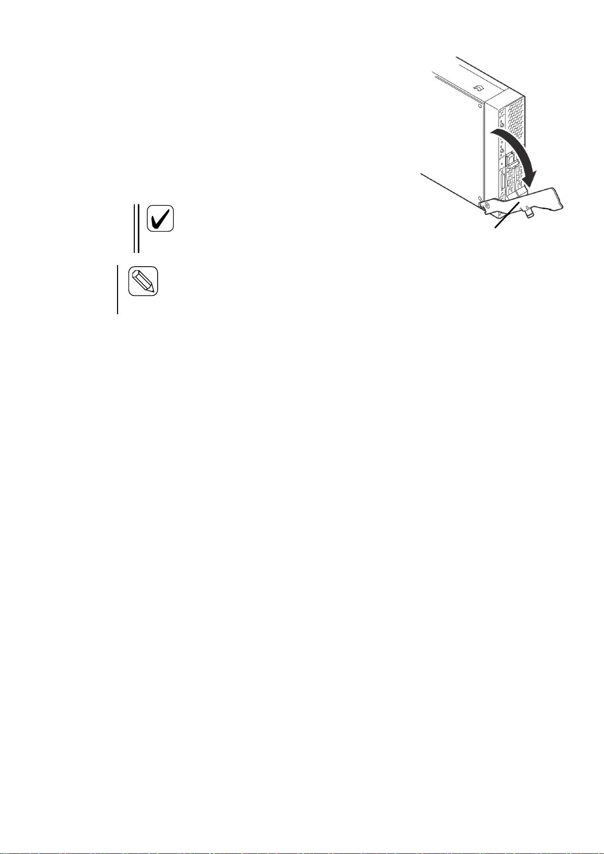
47
Check
When you insert the CPU blade into the
blade enclosure, make sure the pins on the
blade enclosure frame and the ejector of the
CPU blade fit correctly.
Hint
If the pins on the blade enclosure frame and the ejector of the CPU blade do not fit
correctly, move the CPU blade right and left to adjust the position.
When you install a half-height blade, a separator should be installed. When you
install a full-height blade, remove the separator if it is installed.
The ejector facing
down
3. If the CPU blade has any covers on the connectors on the
side that is inserted into the blade enclosure, remove them.
4. Open the CPU blade ejector. If the ejector is secured by a
screw, loosen it.
5. Hold the CPU blade with its midplane connector facing the
blade enclosure and the ejector facing down.
6. Put the end of CPU blade board on the guide rails located at
the upper and lower sides of the blade enclosure and slowly
push the CPU blade into the blade enclosure.
7. Press the ejector firmly to lock it. Tighten the screws to secure the CPU blade.
8. Write down the information of the installed CPU blade on the blade management sheet that
comes with the blade enclosure.
If a sticker is attached, write down the information on the sticker and affix it to the management
sheet. Keep the management sheet in a safe place.
Page 48

48
Removing a CPU blade
(1)
(2)
Follow the steps below to remove a CPU blade.
Depending on the CPU blade type, a different procedure may be required. In this case, follow the
instructions in the User’s Guide of the CPU blade instead.
1. Shut down the OS of the CPU blade and turn the power off. For information on how to shut
down the OS of a CPU blade and how to turn the power off, see “Powering on and off a CPU
blade” and the User’s Guide of the CPU blade.
2. Loosen the screws securing the CPU blade.
3. Open the ejector to remove the CPU blade from the blade enclosure.
If you want to run the system with the CPU blade removed, attach a slot cover. When a
full-height CPU blade is removed, a full-height CPU slot cover may need to be installed on a
blank slot. For details, see “Notes for installation of a full-height and single-wide blade” in
“Installing a CPU blade.” For information on a full-height CPU blade slot cover, see
“Assembling a full-height CPU blade slot cover.”
Page 49

49
Assembling a full-height CPU blade slot cover
Important
Keep all screws.
To avoid screws and parts falling into the cabinet, device, or module,
do not assemble a full-height CPU blade slot cover near any cabinet,
device, or module.
Right side
Left side
Part A
Part B
When a full-height CPU blade is installed on a blade slot block, one full-height CPU blade slot
cover should be installed on the blank slot in the same block. By combining two half-height CPU
blade slot covers, a full-height CPU blade slot cover can be assembled. See the following
instructions to assemble a full-height CPU blade slot cover.
Use one of the two CPU blade slot covers for the upper level and the other for the lower level.
Start with the CPU blade slot cover for the upper level.
1. Remove 4 screws from the right side
and 2 screws from the left side.
2. Separate the slot cover into two
components (hereafter referred to as
Part A and Part B).
The CPU blade slot cover for the upper level is now ready to be combined.
Page 50

50
Right side
Left side
To the center of
the elongated
hole
Right side
Move on to the CPU blade slot cover for the lower level.
3. Remove the top 2 screws from the right side.
4. Loosen the lower 2 screws on the right side
and the 2 screws on the left side.
5. Extend the CPU blade slot cover until the 2
screws on the right side line up with the
center of the elongated hole. Tighten the 4
screws to secure the blade slot cover.
The CPU blade slot cover for the lower level is now ready to be combined.
Page 51

51
CPU blade slot cover for the
lower level
(includes Part B of the CPU
blade slot cover for the upper
level)
Part A of the CPU
blade slot cover for
the upper level
Part B of the CPU blade slot
cover for the upper level
CPU blade slot cover for the
lower level
6. Use the screws removed in Step 1 to connect Part B of
7. Connect Part A of the CPU blade slot cover for the
the CPU blade slot cover for the upper blade
(described in Step 2) to the CPU blade slot cover for
the lower level.
upper level to the blade slot cover assembled in Step 6.
Page 52

52
Screw at the bottom of the
elongated hole
Right side
Left side
8. Use the 4 screws removed in Step 1
and 3 to fasten 4 places in the right
and left (2 each in the right and left)
to secure the blade slot covers. The
screws should be tightened at the
bottom of the elongated holes (the
position where a CPU blade slot
cover is extended most) as shown in
the figure.
Page 53

53
Disassembling a full-height CPU blade slot cover
Important
Keep all screws.
To avoid screws and parts falling into the cabinet, device, or module,
do not disassemble a full-height CPU blade slot cover near any cabinet,
device, or module.
Screw at the top of the
elongated hole
Right side
Left side
To disassemble a full-height CPU blade slot cover into the original two CPU blade slot covers, see
the "Assembling a full-height CPU blade slot cover" and reverse the steps.
When you disassemble a full-height CPU blade slot cover into the original CPU blade slot covers,
note the following.
・ To restore the original CPU blade slot
covers, both of the blade slot covers
should be secured by screws at the top
of the elongated holes (the position
where a CPU blade slot cover is
shrunk most) as shown in the figure.
Page 54

54
Important
The EM card that can be installed on the blade enclosure is N8405-027.
Hint
Installing another EM card on the blade enclosure in addition to the EM card
included as standard on the blade enclosure allows for auto switching between the
active and the standby EM card for redundancy functions. For details, see
"Replacing modules."
(1)
Slot 1
Slot 2
Slot 1
Slot 2
(2)
Installing the EM card
The following illustration shows where EM cards can be installed:
The EM card that is included as standard should be installed on (1) in the illustration below. If you
add another EM card, it should be installed on (2). Attach a slot cover to a slot where no EM card is
installed.
Page 55

55
Installing an EM card
Make sure to follow the instructions and notes to use the blade enclosure and other
devices safely. There is a risk of death or serious injury. For more information, see
the descriptions on page 3.
● Do not place your hands inside the blade enclosure.
● Do not install or remove two or more EM cards at the same time.
Important
Keep the removed slot cover in a safe place.
Important
Do not hold the release lever to install the EM card. If you hold the release lever, it may
be damaged.
Hint
Push the front side of the EM card carefully until it is inserted into the end of the
blade enclosure and the release lever closes slightly.
WARNING
Follow the steps below to install an EM card. An EM card can be installed or removed even if the
blade enclosure is powered on. An example of installation is provided. Follow the same steps for
installation on another slot.
1. When the slot where you wish to install an EM card has a slot cover, pull the release lever
located at the top to remove the slot cover.
2. Hold the left and right sides of the EM card with the release lever side facing up and slowly
insert it into the blade enclosure.
3. Press the frame of the EM card front with your thumbs while the release lever is fully opened to
slowly insert the EM card into the end of the blade enclosure.
4. Close the release lever slowly while carefully pressing the front of the EM card. The midplane
connector of the EM card is connected to the midplane connector of the blade enclosure.
Page 56

56
Removing an EM card
Check
Fully open the release lever until it stops.
Important
Do not hold the release lever to remove
the EM card. If you hold the release
lever, it may be damaged.
(1)
(2)
Follow the steps below to remove an EM card.
1. If any cables are connected to the EM card, remove them.
2. Open the release lever. When you open the
release lever, press the stopper securing the
release lever rightward.
3. Hold the release lever and pull the EM card
out of the blade enclosure until you can
hold its frame with both of your hands
(approximately 10cm).
4. Firmly grip the right and left sides of the EM card to remove it from the blade enclosure.
If you want to use the blade enclosure with the EM card removed, attach a slot cover.
5. Close the release lever of the EM card.
Page 57

57
Important
The fan unit that can be installed on the blade enclosure is N8405-026.
The fan unit N8405-026 is a set of two fan units.
The number of fan units required depends on the number of modules, such as CPU blades.
See "Fan unit installation guide" to add fan units as necessary. The blade enclosure is
equipped with four fan units as standard.
Slot 1
Slot 2
Slot 3
Slot 4
Slot 5
Slot 6
Slot 7
Slot 8
Slot 9
Slot 10
Installing a fan unit
Additional fan units are options that can be installed when more fans are needed according to the
number of CPU blades or other modules installed on the blade enclosure. See "Components"
described earlier.
The following illustration shows slots where fan units can be installed:
Page 58

58
Important
Slot covers that can be installed on fan unit slots of the blade enclosure are fan slot
covers N8405-037.
Slot 1
Slot 2
Slot 3
Slot 4
Slot 5
Slot 6
Slot 7
Slot 8
Slot 9
Slot 10
Slot 1
Slot 2
Slot 3
Slot 4
Slot 5
Slot 6
Slot 7
Slot 8
Slot 9
Slot 10
When four fan units (factory default) are installed
When six fan units are installed (four units as factory default plus
two additional units)
Slots on which fan units are installed depend on the total number of fan units installed on the blade
enclosure. Install fan units on the slots with the "○" mark in the following illustrations according to
the number of fan units you are installing. Attach slot covers to slots with no fan units. The total
number of fan units that should be installed is determined by the number and types of modules that
are installed. For information on the number of fan units that should be installed, see "Fan unit
installation guide."
Page 59

59
Slot 1
Slot 2
Slot 3
Slot 4
Slot 5
Slot 6
Slot 7
Slot 8
Slot 9
Slot 10
When eight fan units are installed (four units as factory def
ault plus four additional units)
Page 60

60
Fan unit installation guide
Slot 1
Slot 2
Slot 3
Slot 4
Slot 5
Slot 6
Slot 7
Slot 8
Slot 9
Slot 10
Slot 11
Slot 12
Slot 13
Slot 14
Slot 15
Slot 16
B A B B C
C C
C B A B B C C
C
C
In principle, blades are installed on slots starting from the far-left slot, although there are exceptions depending
on the number and types of blades. See the User's Guides of the blades.
With four fan units (factory default), blades in section A in the following illustration (blade slots 1 and 9) can
be cooled; with six fan units, blades in sections A and B (blade slots 1 to 4 and 9 to 12) can be cooled; with
eight fan units, blades in sections A, B, and C (all blade slots) can be cooled.
When a N8406-019 4G FC switch (12 ports) is installed, up to eight CPU blades can be connected to the FC
switch (12 ports). These CPU blades are installed on the blade slots 1 to 8. CPU blades on the blade slots 9 to 16
cannot connect to a FC switch (12 ports).
When a N8406-019 4G FC switch (12 ports) is installed, full-height blades can connect to the FC switch (12
port). However, there are restrictions of mezzanine slots to which the blades can connect and slot ports. For
details, see "Internal connection between CPU blades and switch modules" on page 32.
When a CPU blade is installed on any of blade slots 5 to 8 or 13 to 16, eight fan units are required whether or
not there is CPU blade in the blade slots 1 to 4 and 9 to 12.
When the blade enclosure has a N8406-019 4G FC switch (12 ports), four blades with Fibre channel mezzanines
on the blade slots 1 to 4, and four blades without Fibre channel mezzanines on the blade slots 9 to 12, six fan
units are required for cooling.
When an even number of fan units are installed, the redundancy mode is N+1. For example, eight fans are
installed for 16 blades. If one of the fans fails (i.e., seven fans are working) successful operation can continue.
If two of the fans fail (i.e., six fans are working), operation may stop due to a temperature abnormality detected
by a server or switch module.
If only one NEC Express5800/120Bb-m6 is installed, it will use the blade slots 1 and 2 with nothing on the blade slot 9. However,
six fan units are required because the blade slot 2 is used.
When you add a fan unit, you may have to relocate fan units that are already installed. Install fan units in the correct slots by
referring to the instructions described on previous pages.
For information on the number of slots used by blade products, see "Installable CPU blades" and the User's Guides of the blades.
Page 61

61
Installing a fan unit
Make sure to follow the instructions and notes to use the blade enclosure and other
devices safely. There is a risk of death or serious injury. For more information, see
the descriptions on page 3.
● Do not place your hands inside the blade enclosure.
● Do not install or remove two or more fan units at the same time.
Important
The upside and downside of a fan unit are inverted on the upper level (fan unit slots 1 to 5)
and the lower level (fan unit slots 6 to 10) of the blade enclosure. Even if you attempt to
install a fan unit in the wrong direction, you cannot install it, and the connector may be
damaged.
Important
Keep the removed slot cover in a safe
place.
WARNING
(1)
(2)
A fan unit can be installed/removed even if the blade enclosure is powered on. The following
section is an example of installing a fan unit. Use the same method to install fan units to other slots.
1. If there is a slot cover on the slot where you
wish to install the fan unit, remove the slot
cover. If the slot cover is on a slot on the
upper level of the blade enclosure (fan unit
slots 1 to 5), push the slot cover ejector
upward. If the slot cover is on the lower
level (fan unit slots 6 to 10), push the
ejector downward. The illustration on the
right depicts removal from the upper level.
Push the ejector downward if you remove a
slot cover from the lower level.
Page 62

62
Important
Do not hold the fan unit lever to install the fan unit. If you hold the fan unit lever, it may be
damaged.
Removing a fan unit
Important
● Do not hold the fan unit lever to remove the fan unit. If you hold the fan unit lever, it may be
damaged.
● Turn the fan unit lever toward the indicated direction. If you turn the fan lever toward the
wrong direction, the fan lever may be damaged.
(1)
(2)
Handle
Fan unit lever
Fan unit lever
Turning the fan unit
lever leftward
Pull the fan
unit.
2. To install a fan unit on the upper level of the blade
enclosure, hold the fan unit handle and the bottom
of the unit firmly with the handle facing down and
insert the fan unit slowly into the blade enclosure
halfway (approximately 10 cm). To install a fan
unit on the lower level of the blade enclosure, hold
the fan unit handle and the bottom of the unit
firmly with the handle facing up and insert the fan
unit slowly into the blade enclosure halfway
(approximately 10 cm). The illustration on the
right depicts installing a fan unit on the upper
level. For installation on the lower level, the
fan unit is turned upside down.
3. Slowly push the fan unit handle to insert the fan unit into the blade enclosure.
Follow the steps below to remove a fan unit:
1. Check which fan unit you wish to remove.
2. Hold the fan unit handle to pull the fan unit
out of the blade enclosure approximately 10
cm while turning the fan unit lever leftward.
The illustration on the right depicts pulling
out a fan unit from the upper level. For
removal from the lower level, the fan unit is
turned upside down.
3. Hold the bottom of the fan unit firmly and
remove it from the blade enclosure. If you
want to use the blade enclosure without
installing a new fan unit on the fan unit slot,
attach a slot cover.
Page 63

63
Important
● The front bezel that can be installed on the blade enclosure is N8405-028.
● When the front bezel is attached to the blade enclosure, a front door cannot be attached to the
rack on which the blade enclosure is installed.
Filter cleaning
Installing the front bezel
The front bezel is a recommended option to protect the CPU blades installed on the blade
enclosure.
Installation and removal of the front bezel and its filter should be done only by sales maintenance
personnel. Contact your sales maintenance personnel to install or remove the front bezel and its
filter.
The front bezel has a filter on its backside. Frequency of filter cleaning depends on how the blade
enclosure is used and the environment where the blade enclosure is installed. It is recommended to
clean the filter at least once every three months. Check the filter and clean it as necessary. Open the
front bezel and clean the filter by using a vacuum cleaner. For information on how to open the front
bezel, see "How to open the front bezel."
Page 64

64
Opening the front bezel
Make sure to follow the instructions and notes to use the blade enclosure and other
devices safely. There are risks of a burn, injury, or damage to physical assets. For
more information, see the descriptions on page 3.
Be careful not to hurt your fingers.
CAUTION
Key slot
The front bezel can be opened even if the blade enclosure is powered on. To remove a CPU blade
installed on the blade enclosure, keep the front bezel open (the front bezel is a recommended
option).
For information on how to remove a CPU blade, see "Installing a CPU blade" on page 41.
The following description assumes the front bezel is already attached to the blade enclosure.
1. If the front bezel is locked, insert the included key into the key slot of the front bezel and push
it lightly to unlock.
2. Open the front bezel.
Page 65

65
Closing the front bezel
Key slot
Follow the steps below to close the front bezel. The front bezel can be closed even if the blade
enclosure is powered on. Close the front bezel after installing CPU blades.
For information on installing a CPU blade, see "Installing a CPU blade" on page 41.
The following description assumes the front bezel is already attached to the blade enclosure.
1. Close the front bezel.
2. If you want to lock the front bezel, insert the included key into the key slot of the front bezel
and push it lightly to lock.
Page 66

66
Connecting cables
Important
The SUV cable that can be connected to a CPU blade is K410-150(00).
Local console
Important
● For general operation, do not use CPU blades with a SUV cable connected. If you always use
CPU blades with a SUV cable, there is a risk of damage to the SUV cable or connector.
● Make sure not to snag or pinch the SUV cable. There is a risk of damage to the SUV cable,
CPU blades and the blade enclosure, and other modules.
Connect cables according to the requirements of your environment. For information on connecting cables,
see the manuals of the installed devices.
Front
Use a K410-150(00) SUV cable, which is sold separately, to connect the SUV connector located
on the front side of a CPU blade to the local console.
* The SUV connector and the local console are not supported by some CPU blades. For details, see
the User's Guide of the CPU blade. Even if there is an SUV connector present, the local console
may not be supported.
Connect a USB keyboard to the keyboard/mouse connector of the SUV cable, and then connect a
USB mouse to the USB connector of the keyboard. The cable of the display device should be
connected to the monitor connector of the SUV cable. See the User's Guide of the CPU blade as
well.
It is assumed that the local console is used for installation of an OS and for emergency operation.
For general operation, do not use CPU blades with a SUV cable connected. Some CPU blades do
not support installation of an OS through the SUV cable. For details, see the User's Guide of the
CPU blade.
Page 67

67
Blade enclosure
USB connector
Monitor connector
Serial connector
(Not connected)
SUV cable
USB connector
FDD
These input and output devices are collectively called "local console." CPU blades on the blade
enclosure can be directly operated when they are connected to a keyboard, video monitor, and
mouse via the SUV cable attached to the blade enclosure.
The following devices are recommended for the local console:
Note: Some CPU blades may require a local console different from the one described in this guide.
In this case, follow the instructions in the User's Guide of the CPU blade instead.
Recommended models
- 104-key Keyboard (USB) (N8870-002AF)
- Mouse (USB) (N8870-010A)
- External Floppy Disk Drive Unit (N8160-74)
Page 68

68
EM serial console
Blade enclosure
PC
CLI
Rear
Connect network cables (RJ-45), interface cables to be connected to switch modules, and power
cords to the rear of the blade enclosure.
When the serial (COM) port of an EM card is connected to a PC by a serial cable (D-Sub 9-pin
connector, crossover cable), you can operate the CPU blades and check their status.
These input and output devices are called "EM serial console." You can operate and check the
status of CPU blades and other modules on the blade enclosure on a PC via the serial (COM) port.
Use a crossover cable for serial cable connection.
Use a device satisfying the following recommended specifications for the EM serial console (the
EM serial console, EM console, and LAN console can share one PC).
Recommended specifications
CPU : Pentium processor (600MHz) or faster
Memory : 1GB or larger
Hard disk drive : 400MB or larger
LAN : 1 port (100Mbps or faster)
Serial : 1 port
Recommended OS
: Windows Server 2003 Standard Edition SP1 or Enterprise Edition R2
Windows 2000 Server, Advanced Server, or Professional (SP4 or later
required)
Java Runtime Environment: JRE 1.4.2_03 recommended (contained in NEC
EXPRESSBUIDER)
Web server/servlet container: TOMCAT 4.1.29 recommended (contained in
NEC EXPRESSBUIDER)
Browser : Internet Explorer 6.0 or later
Page 69

69
EM console
Important
●The default IP address of the EM card is 192.168.1.8 ~11 (subnet mask: 255.255.255.0).
Connect to a network with a subnet mask that allows this IP address and configure the
initial settings of the network from the EM console on the same network. Then, connect to
the network you intend to use. For information on how to configure, see Initial settings in
Command-line interface (CLI) (EM card)." Make sure that there is no network device
with the same IP address as the EM card on the network.
● All EM cards have the same default IP address. Configure the IP addresses before allowing
multiple EM cards to access the same network.
● The management LAN connecter of the EM card only supports auto negotiation mode.
Blade enclosure
(Network hub)
tftp
PC
CLI
ESMPRO Mg
DianaScopeMg
(NTP server)
Example of connection
When the LAN connector (management LAN connector) of an EM card is connected to a PC by a
network cable (RJ-45), you can remotely control the CPU blades. You can virtually allocate
modules, such as DVD, CD, and floppy disk drives on the PC to the CPU blades (i.e., remote
media), and operate and check the status of the CPU blades.
These input and output devices are collectively called "EM console" and the network is called
"management LAN." You can operate and check the status of CPU blades and other modules on
the blade enclosure on a PC via a LAN network.
For the EM console, use a device whose specifications are equivalent to the device used for the EM
serial console (the EM serial console, EM console, and LAN console can share one PC).
Page 70

70
LAN console
Important
● Make sure the IP addresses have subnet masks available on the network.
● Check that the IP addresses you are configuring do not conflict with any network devices on
the network.
(Network hub)
Blade enclosure
ESMPRO Mg
DianaScopeMg
PC
Network Mg
When the LAN connector of a switch module or pass-through card is connected to a PC by a
network cable (RJ-45), you can remotely control and operate CPU blades.
These input and output devices are collectively called "LAN console" and the network is called
"user LAN." You can operate CPU blades and switch modules on the blade enclosure on a PC via a
LAN network.
For the LAN console use a device whose specifications are equivalent to the device used for the
EM serial console (the EM serial console, EM console, and LAN console can share one PC).
For details on connection and how to use the LAN console, see the User's Guides and manuals of
the GbE intelligent switch (L2)(N8406-022), GbE intelligent switch (L3)(N8406-023), GbE
pass-through card (N8406-016), and CPU blades.
Page 71

71
SFP connector (switch module)
SFP connector (pass-through card)
See the User's Guides of the 4G FC switch (12 ports) (N8406-019), 4G FC switch (24 ports)
(N8406-020), and GbE intelligent switch (L3)(N8406-023).
See the User's Guide of the 4G FC pass-through card (N8406-017).
Page 72
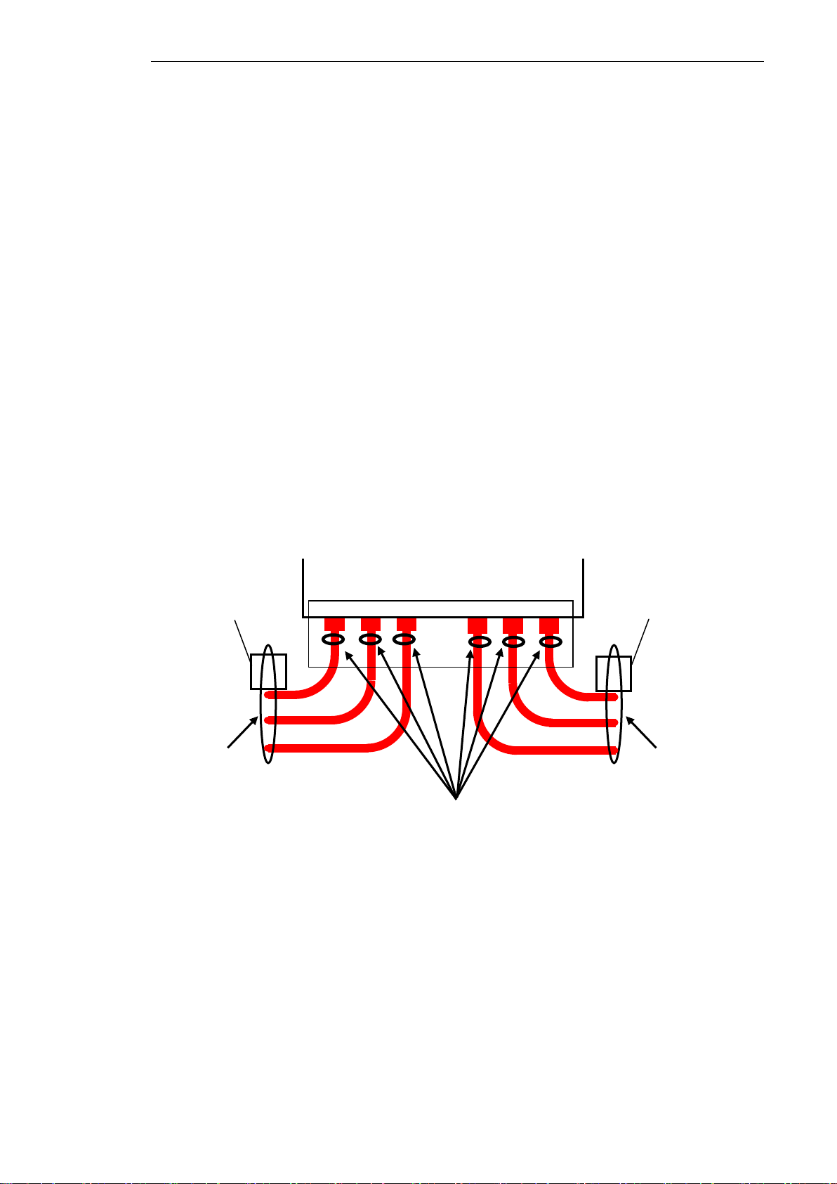
72
Power connector
Fix to the rack frame.
Fix to the blade enclosure.
Blade enclosure
Rack frame
Overhead view
The illustration depicts four additional power supply units installed.
Fix to the rack frame.
Rack frame
Connect the power cords to the AC inlets of the power units installed on the power unit slots 1 and
4 at the rear of the blade enclosure (these units are standard equipment). If any optional power units
are installed on the power unit slots 2, 3, 5, and 6, connect the power cords to the AC inlets of the
optional power units as well.
If the N+N redundant mode is set as the power redundancy mode, power units in the slots 1 to 3
form power system 1 while power units in the slots 4 to 6 form power system 2. Note this when
you connect a device such as a power supply tap or uninterruptible power supply system.
When you connect the power cords to the blade enclosure, use the cable ties that are shipped with
the blade enclosure to fix the power cords to the rack. All power cords should be fixed to the blade
enclosure by cable clamps or to power supply retention ties located near the AC inlets. Cable
clamps or cable ties are shipped with the blade enclosure. For details about installing/removing
power cords with cable clamps, see "Installing cable clamps" and "Removing a power cord form a
cable clamp". Power cords connected to the AC inlets of the power unit slots 1 to 3 should be
routed rightward horizontally and fixed to the rack by cable ties at the rear. Power cords connected
to the AC inlets of the power unit slots 4 to 6 should be routed leftward horizontally and fixed to
the rack by cable ties at the rear. Excessive force should not be applied to a spot where an AC inlet
touches a power cord.
For information on installing an optional power unit, see "Power unit" on page 81.
When AC power is supplied to a power unit, its power LED is green.
Page 73

73
Power supply
retention tie
Cable tie
Draw the cable tie tip
through the cable tie hole
and then through a retention
tie hole by referring to this
illustration.
* When cable clamps are
provided as standard, use
them instead.
Power cord
Rack frame
Rear view
The illustration depicts fouraddition
al power supply units installed.
Fix to the rack frame.
Fix to a blade enclosure.
Rack frame
Fix to the rack frame.
Blade enclosure
Fix a power cord to a power supply retention tie
by a cable tie
Page 74
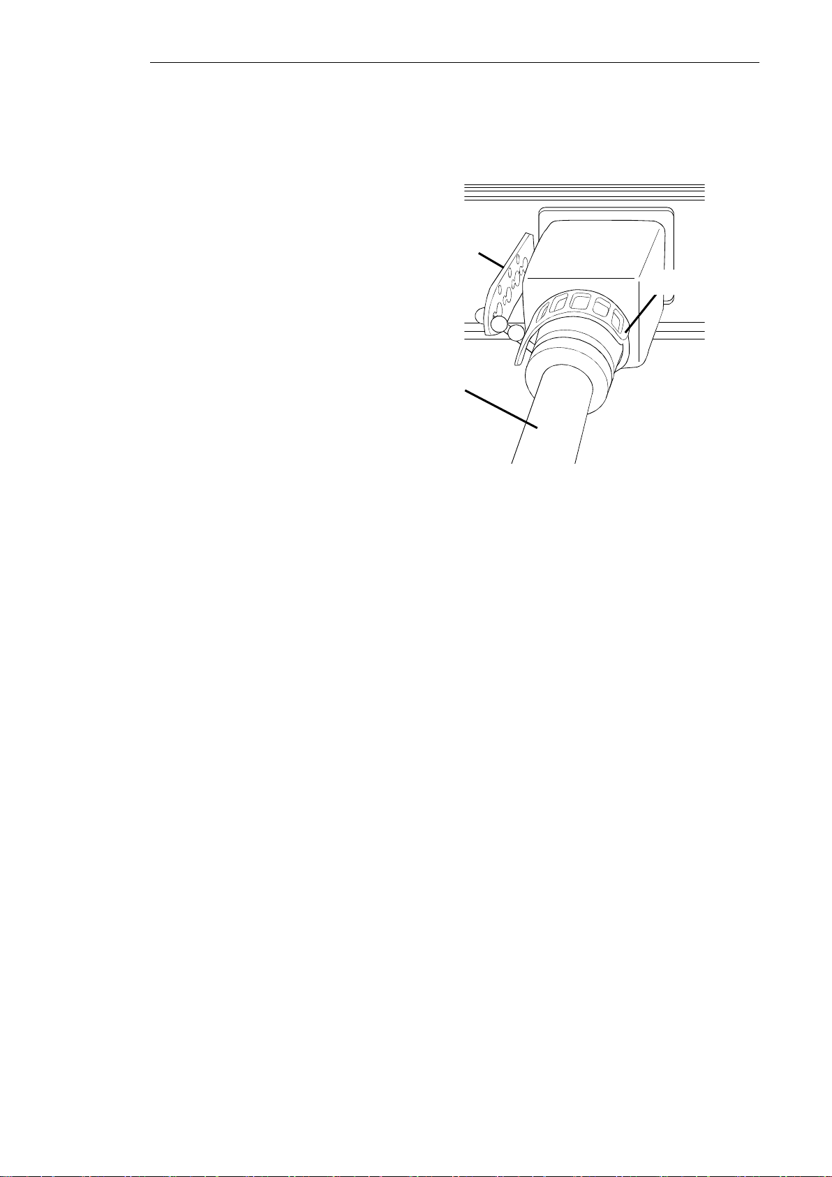
74
Installing cable clamps
Power supply
retention tie
Cable tie
Power cord
Follow the steps below to install cable clamps.
1. Remove cable ties. When cable ties
are not fixed, skip this step.
When power cords are fixed to po
wer supply retention ties, remove t
he cable ties.
2. Remove the power supply retention ties. When the blade enclosure has no power supply retenti
on ties, skip this step.
When the blade enclosure has power supply retention ties, remove them with pliers.
Page 75

75
Check
The shapes of cable clamps (L) and (R) are not the same. See the following
illustrations to check the locations of the tabs on the cable clamps and the
direction in which they should be installed.
Cable clamp (L)
For Power unit 4 - Power unit 6
Cable clamp (R)
For Power unit 1 - Power unit 3
Blade enclosure (rear view)
Tab of cable clamp
3. See the following illustrations to check where the cable clamp should be installed.
Page 76

76
Check
You will hear a click sound when you attach the cable clamp to the blade
enclosure.
①
②
Clip
Clip
4. Attach a cable clamp (L) to the blade encl
osure.
Place the cable clamp (L) under the power
cord and adjust the power cable to the
clip of the cable clamp.
Open the clip of the cable clamp and inser
t the power cord into the clip. Do this for
each power cord (up to three cords).
Bring the cable clamp to the blade enclosu
re and carefully insert the tabs of the cabl
e clamp into the slots on the blade enclos
ure.
5. Secure the power cords to the cable clam
p (L).
Slide the clip of the cable clamp to the en
d of the plug cap of the power cord. The
n, close both sides of the clip firmly to s
ecure the power cord. Do this for each po
wer cord (up to three cords).
6. Attach a cable clamp (R) to the blade enclosure and secure the power cords (up to three cord
s) to the cable clamp in the same way (see Steps 4 and 5).
Page 77

77
Removing a power cord form a cable clamp
Follow the steps below to remove a power cord from a cable clamp.
Firmly hold the clip of the cable clamp with pliers and twist it to release the clip.
Remove the power cord.
Page 78

78
Important
● Note that a maximum of 2250W/2273VA power is supplied from each power unit.
● Fix power cords firmly to the blade enclosure. If power cords are not fixed, they may be
removed while the devices are running, which can result in data loss or malfunction of the
device.
● Contact NEC's sales representative if you use an uninterruptible power supply system.
Page 79

79
Emergency power off (EPO)
Make sure to follow the instructions and notes to use the blade enclosure and other
devices safely. There is a risk of death or serious injury. For more information, see
the descriptions on page 3.
● In case of emergency, EPO should be performed quickly. Clearly define scenarios
to perform EPO in advance. Operate your system with an understanding of these
scenarios and the procedure to perform EPO.
● Place the power supply tap in a place where it is noticeable and easy to access so
that power can be shut down in an emergency.
Important
Data may be corrupted when emergency power off is performed.
Power supply tap
CAUTION
Blade Enclosure
(SIGMABLADE-H)
Power unit
Power cord
Power supply tap
(1)
(2)
(1)
Turn the power cord plug left.
(2) Disconnect
Power cord
Power supply tap
Closeup
In of the event of an environmental disaster or problem (e.g., fire, earthquake, etc.), the emergency
power off (EPO) procedure can be performed to shut down computers, uninterruptible power
supply systems (UPS), and air conditioners to prevent further damage.
Because there is a risk of data corruption when EPO is performed, clearly define scenarios to
perform EPO in advance. Operate your system with an understanding of these scenarios and the
procedure to perform EPO.
In case of emergency, disconnect the power cords attached to the AC inlets of the blade enclosure
from the power supply tap.
Place the power supply tap in a place where it is noticeable and easy to access so that the power
cords can be disconnected quickly.
Example: How to disconnect L6-20P power cord.
Disconnect all power cords connected to the blade enclosure according to the illustration above.
Page 80

80
Emergency power off switch
For the safety of the entire computer room, install an emergency power off switch that allows
shutdown of power supplied to all devices in the computer room in case of emergency.
This emergency power off switch should be installed near the main doorway so that an operator
can use it when he/she evacuates the room. The emergency switch should not require technical
skill or expertise to use.
Page 81

81
Power unit
Make sure to follow the instructions and notes to use the blade enclosure and other
devices safely. There is a risk of death or serious injury. For more information, see
the descriptions on page 3.
● Air exhausted from power fans may get hot.
Important
● The power unit that can be installed on the blade enclosure is N8405-025F.
● The number of power units required depends on the number of modules, such as CPU blades,
and the power redundancy mode selected. See "Power unit installation guide" and add power
units as necessary. The blade enclosure is equipped with two power units as standard.
WARNING
Slot 1
Slot 2
Slot 3
Slot 4
Slot 5
Slot 6
Additional power units are options that are installed when CPU blades and other modules on the
blade enclosure require more power units or when you want to enable power redundancy functions.
The following illustration shows slots where power units can be installed:
Page 82

82
Important
Slot covers that can be installed on power unit slots of the blade enclosure are power
slot covers N8405-036.
(1)
(1)
(2)
(3)
Slot 1
Slot 2
Slot 3
Slot 4
Slot 5
Slot 6
(4)
(5)
The power units that are equipped as standard should be installed on (1) (there are two slots shown
as (1)). When additional power units are installed, install them in the order of (2) to (5) as shown in
the illustration below. Slots with no additional power unit installed should have slot covers attached.
For information on the number of power units required, see "Power unit installation guide."
Page 83

83
Total power
consumption (watt)
Number of power
units required
(N+1 redundancy
mode)
Number of power
units required
(N+N redundancy
mode)
Remarks
2250 or smaller
2
2
The number of power units required
include the two power units that are
installed as standard.
4500 or smaller
3
4
6750 or smaller
4
6
9000 or smaller
5
Not available
Important
The N+N redundant mode cannot be used if the total amount of power consumption
is over 6750 watts. Use the N+1 redundant mode instead.
Power unit installation guide
The number of power units required is determined by the total power consumption of blades. See
the following to determine the number of power units required for your system.
*If you need more detailed information, please contact your sales agent.
1. Calculate the total power consumption according to the following formula:
Total power consumption (watt) = total power consumption of blades (watt) + 1340 (watt) (power
consumption of the blade enclosure*)
*The power consumption of the blade enclosure includes power consumption of switch modules, fan units, etc.
To find the total power consumption of the blades, add up the power consumption of all the blades installed on the
blade enclosure. The amount of power consumption varies according to the blade type. For information on the power
consumption of blades, see the User's Guides or Configuration Guides of the blades.
2. Determine the number of power units required by using the value for total power consumption
quoted by the formula above.
As of 2008 April
Page 84

84
Installing a power unit
Make sure to follow the instructions and notes to use the blade enclosure and other
devices safely. There is a risk of death or serious injury. For more information, see
the descriptions on page 3.
Do not place your hands inside the blade enclosure.
Do not insert a wire or metal object.
Important
● Keep the slot cover that has been removed in a safe place.
● Do not remove any slot covers other than the one attached to the slot where you
wish to install the power unit.
WARNING
(1)
(2)
Follow the steps below to install a power unit. A power unit can be installed or removed even if the
blade enclosure is powered on. Power units can be removed only in a redundancy configuration. If
you want to remove a power unit in a non-redundancy configuration, power off all devices on the
blade enclosure. Installation can be done in both redundancy and non-redundancy configurations.
An example of installation is provided below. Follow the same steps for installation on other slots.
1. Check that the AC inlet corresponding to the slot on where you to install a power unit has a
power cord connected. If not, connect a power cord.
2. If the power unit is installed on the slot 3 or 4, slide the key box so that it will not impair the
installation. For information on moving the key box, see "Moving the key box."
3. If the slot on which you are installing
the power unit has a slot cover,
remove it.
Pull the slot cover hook forward.
4. Put the power unit on a clean, flat
table and open the power unit ejector.
When you open the power unit ejector,
push the power unit stopper securing
the power unit ejector downward.
Page 85

85
Important
Do not touch the plug terminals of the power unit. Do not insert a wire or metal object. Do not
let dust or waste enter the power unit.
Removing a power unit
Important
To remove a power unit in a non-redundant configuration, power off all devices in the blade
enclosure.
(1)
(2)
5. Hold the power unit frame with the power unit stopper facing up. Push the frame at the front of
the power unit and slowly insert the power unit into the blade enclosure.
6. Close the power unit ejector.
Follow the steps below to remove a power unit:
1. Check which power unit you wish to remove.
2. If the power unit you wish to remove is in the slot 3 or 4, slide the key box so that it will not
impair removal. For information on moving the key box, see "Moving the key box."
3. If the power units are not in a redundancy configuration, power off all the CPU blades that are
installed on the blade enclosure.
4. While releasing the power unit stopper
by pushing it down, pull the power unit
ejector forward. Release the stopper
and hold the ejector to pull out the
power unit about 20 cm.
5. If the fan in the power unit is still working, wait until it stops.
6. Hold the power unit ejector and the bottom of the frame, and slowly remove the power unit
from the blade enclosure.
If you want to use the blade enclosure with the power unit removed from the slot, attach a slot
cover to the slot.
Page 86

86
Opening the power unit cover
Make sure to follow the instructions and notes to use the blade enclosure and other
devices safely. There are risks of a burn, injury, or damage to physical assets. For
more information, see the descriptions on page 3.
Do not use the blade enclosure with its covers and fans removed. If you use the
blade enclosure without them, the cooling efficiency inside the blade enclosure
degrades, causing malfunction. Also, dust may get in and cause a fire or electric
shock.
Be careful not to hurt your fingers.
CAUTION
(2)
(1)
Key slot
Power unit cover
The power unit cover can be opened even if the blade enclosure is powered on. When you install or
remove a power unit, keep the power unit cover open. If you keep using the system, close the
power unit cover.
For information on how to remove a CPU blade and a power unit, see "Installing a CPU blade"
on page 41 and "Power unit" on page 81, respectively.
1. If the optional front bezel is attached, open the front bezel. For information on opening the
front bezel, see "Installing the front bezel."
2. If the power unit cover is locked, insert the included key into the key slot of the power unit
cover to unlock it.
3. Open the left door of the power unit cover.
4. Open the right door of the power unit cover.
Page 87

87
Closing the power unit cover
Moving the key box
Key slot
(1)
(2)
Push up the lock to release the
key box and move it rightward or
leftward.
Key box
(1)
(2)
Lock
The power unit cover can be closed even if the blade enclosure is powered on. After installing the
power units, close the power unit cover.
For information on how to install a CPU blade and a power unit, see "Installing a CPU blade" on
page 41 and "Power unit" on page 81, respectively.
1. If the key box is not located at the key slot
of the power unit cover, slide the key box
to place it in an appropriate position. For
information on how to move the key box,
see "Moving the key box."
2. Close the right door of the power unit
cover.
3. Close the left door of the power unit cover.
4. If you want to lock the power unit cover, insert the included key into the key slot of the power
unit cover to lock it.
5. If the optional front bezel is attached, close the front bezel. For information on closing the front
bezel, see "Installing the front bezel."
Follow the steps below to move the key box. The key box is used to fix and lock the power unit
cover. You can slide it right/leftward as necessary when you are installing or removing a power
unit.
1. Press the key box lock.
2. Slide the key box
rightward or leftward to
an appropriate position
while pressing the lock.
3. Release the key box lock.
Page 88

88
Power on and off
Make sure to follow the instructions and notes to use the blade enclosure and other
devices safely. There is a risk of death or serious injury. For more information, see
the descriptions on page 3.
● Do not place your hands inside the blade enclosure.
Important
Make sure to follow the instructions to power on and off devices. If you do not
follow the instructions, data may be corrupted or the devices may malfunction.
Powering on and off the blade enclosure without uninterruptible power supply
system (UPS).
WARNING
Powering on and off the blade enclosure
This section describes how to power on and off a blade enclosure that is connected to the power
distribution board via a power supply tap.
Depending on the types of modules and units and how they are used on the blade enclosure, a
different procedure may be required. In this case, follow the instructions in the User's Guides of the
modules and units instead.
To power on the blade enclosure, power on the power distribution board to which the power supply
tap is connected.
To power off the blade enclosure:
1. Shut down all the CPU blades and power them off.
2. Power off the power distribution board to which the power supply tap is connected.
Page 89

89
Powering on and off the blade enclosure with uninterruptible power supply
system (UPS).
Follow the steps below to power on the blade enclosure using an uninterruptible power supply
system (UPS). When you use a UPS, contact your NEC sales representative.
Depending on the types of modules and units and how they are used on the blade enclosure, a
different procedure may be required. In this case, follow the instructions in the User's Guides of the
modules and units instead.
1. Power on the power distribution board to which the UPS that is installed on the rack is
connected.
2. Power on the UPS that is installed on the rack.
Follow the steps below to power off the blade enclosure.
Depending on the types of modules and units and how they are used on the blade enclosure, a
different procedure may be required. In this case, follow the instructions in the User's Guides of the
modules and units instead.
1. Shut down all the CPU blades and power them off.
2. Power off the UPS on the rack.
3. Power off the distribution board to which the UPS on the rack is connected.
Page 90

90
Important
Before powering on a CPU blade, the EM card should be started whether the CPU
blade is started by its power switch or remotely. If you attempt to power on a CPU
blade before the EM card is started, the CPU blade may not be powered on. In this
case, check to see the EM card is started, and then power the CPU blade on by its
power switch.
Check
If the blade enclosure cord is connected to any power control system such as an
uninterruptible power supply (UPS) system, confirm that the power control system is
powered on.
Hint
It will take a while to start up EM cards. By logging on to an EM card from a CLI and
checking the status of all the CPU blades on the blade enclosure by the SHOW SERVER
LIST command, you can see whether or not the EM card is started. There may be a CPU
blade status indication "unknown" or EM card not started up. For information on the SHOW
SERVER LIST command, see "Commands."
To start up the OS from a peripheral device that is connected to a switch module or
pass-through card, such as storage, power-on should be done in the order starting from
peripheral device (storage), then the switch module/pass-through card, and then the CPU
blade. Confirm that a module is fully started before you power on the next module or device.
Powering on and off a CPU blade
There are four ways to power on and off the CPU blades installed on the blade enclosure. Power on
the video monitor and other connected devices and then power on the CPU blades in one of the
following ways. For information on the CPU blades, including their behavior after power-on and
checking the behavior, see the User's Guides and manuals of the CPU blades.
Note: Some CPU blades require different procedures, in which case the instructions in the
User's Guides of the CPU blades should be followed. Some CPU blades may not
support all the methods to power on/off described here. For details see the User's
Guides and manuals of the CPU blades.
Page 91

91
Powering on and off a CPU blade by its power switch
Powering on a CPU blade by the blade enclosure
Powering on a CPU blade via a network (switch module/pass-through
card)/serial connector (CPU blade)
Hint
By configuring the BIOS settings of the CPU blade, auto power-on by receiving
packets over a network or via a modem connected to the serial connector of a
SUV cable is enabled. Configure the Wake On Events settings of System
Hardware in the BIOS SETUP utility. For details, see the User's Guide of the
CPU blade.
To power on or off a CPU blade from a network connected to the LAN connector
of a switch module/pass-through card, the switch module/pass-through card
should be started up.
Example of NEC Express5800/120Bb-6.
The location of the LED and switch depends on the CPU
blade. For more information, see the User's Guide and
manual of the CPU blade.)
Power
switch
Power
LED
A CPU blade on the blade enclosure can be powered on and off by using the power switch located
on the front of the CPU blade. For details, see the User's Guide and manuals of the CPU blade.
When a CPU blade is powered on by its power switch, the DC power supply from power units on
the blade enclosure starts. Then the power LED of the CPU blade turns green, showing the CPU is
now powered on.
When you either press the power switch of the CPU blade or perform OS shutdown to power off
the CPU blade, the power LED of the CPU blade turns amber, showing the CPU blade is powered
off.
Functions to automatically power on CPU blades on the blade enclosure when the blade enclosure
is powered on are provided. The functions can be enabled by configuring a target CPU blade. If the
CPU blade is configured to disable the functions, the CPU blade is not automatically powered on.
In this case, power on the CPU blade by using its power switch or change its configuration. For
details, see the User's Guide of the CPU blade.
A CPU blade on the blade enclosure can be powered on and off by a network connected to the
LAN connector of a switch module/pass-through card on the blade enclosure or the serial connector
of the SUV cable connected to the CPU blade. For details, see the User's Guides of the CPU blade
and switch module/pass-through card.
Page 92

92
Powering on a CPU blade by the network serial (COM) port of an EM card
Check
Powering on and off of a CPU blade by a CLI should be done by "Administrator" or
a user with the ADMINISTRATOR or OPERATOR access right.
A CPU blade on the blade enclosure can be powered on and off by a network connected to the
management LAN connector of the EM card or the serial port (COM) of the EM card. For details,
see the User's Guide of the CPU blade.
This section describes how to power on and off a CPU blade by a CLI from the EM serial console
or the EM console. For information on other ways to power on and off, see the User's Guide of the
CPU blade. For details of CLI, see "Command-line interface (CLI) (EM card)" and "Command
input Specifications." For information on the EM serial console and the EM console, see
"Connecting cables."
Follow the steps below to power on a CPU blade from a CLI:
1. Confirm that the EM card is powered on.
2. From the CLI of the EM serial console or the EM console, confirm that you have logged on as
"Administrator" or a user with the ADMINISTRATOR or OPERATOR access right. If you
have not, log on as "Administrator" or a user with the ADMINISTRATOR or OPERATOR
access right.
3. From the CLI, run the following command for powering on a specified CPU blade. For details,
see "Commands."
POWERON SERVER <Slot number>
Follow the steps below to power off a CPU blade from a CLI:
1. Confirm that the EM card is powered on.
2. From the CLI of the EM serial console or the EM console, confirm that you have logged on as
"Administrator" or a user with the ADMINISTRATOR or OPERATOR access right. If you
have not, log on as "Administrator" a or user with the ADMINISTRATOR or OPERATOR
access right.
3. From the CLI, run the following command for powering off a specified CPU blade. For details,
see "Commands."
POWEROFF SERVER <Slot number>
Follow the steps below to restart a CPU blade from a CLI.
1. Confirm that the EM card is powered on.
2. From the CLI of the EM serial console or the EM console, confirm that you have logged on as
"Administrator" or a user with the ADMINISTRATOR or OPERATOR access right. If you
have not, log on as "Administrator" or a user with the ADMINISTRATOR or OPERATOR
access right.
Page 93

93
3. From the CLI, run the following command for restarting a specified CPU blade. For details, see
"Commands."
REBOOT SERVER <Slot number>
Page 94

94
Memo
Page 95

95
Memo
Page 96

96
Page 97

97
Command-line interface (CLI) (EM card)
Check
If you are using a CLI for the first time, only "Administrator" can use the CLI.
It is needed to register users other than "Administrator" to use the CLI. For
information on how to register user names for CLI, refer to "Initial settings."
A default password for "Administrator" is printed on the label of an EM card or
the release lever. Each EM card has a different default password for
"Administrator."
Use UTF-8 encoding as a character set of the terminal emulator software. If you
use other encoding, some of the letters may be displayed incorrectly.
Hint
If you cannot enter a command while operating a CLI because the window is not
properly displayed, restart the terminal emulator software or terminate the CLI and
reconnect it.
EM serial console (serial connection)
A command-line interface (CLI) allows configuring and managing the modules installed on the
blade enclosure, including CPU blades and switch modules.
A CLI can be used on the EM serial console and the EM console.
Connecting a cable to a console
For information on how to connect a cable, refer to "EM serial console (serial connection)" and
"EM console (Telnet connection)."
Starting a console
There are three ways to use a CLI.
In any of the three ways, a CLI becomes available by entering a user name and a password from a
command prompt after the CLI is successfully connected. For details, refer to "Command input
Specifications."
To log out, type EXIT on the CLI (you can also log out by typing LOGOUT or QUIT).
You can use a CLI from the EM serial console. Install terminal emulator software that supports a
serial port connection on a PC. Terminal emulator software supporting the serial port is necessary
for the EM serial console. For settings of the software, refer to the manual of the software.
Configure the parameters of the serial cable connection as follows:
― Serial cable connection parameters
Transfer rate : 115200 bps
Data length : 8 bit
Parity : None
Stop bit : 1 bit
Flow control : None
Page 98

98
EM console (Telnet connection)
Hint
To check if the telnet function is enabled, execute the SHOW NETWORK
command (the telnet function is enabled by default). If the function is disabled,
execute the ENABLE TELNET command to enable the telnet function. For details on
each command, refer to "Commands."
Check
The default value of the IP address of an EM card is 192.168.1.8~11 (subnet mask:
255.255.255.0). When connecting to an EM card from the EM console for the first
time, connect to 192.168.1.8
Important
Log in from a secure network because the password is transmitted without
encryption.
EM console (SSH connection)
Hint
Execute the SHOW NETWORK command to check if the SSH function is enabled
(the SSH function is enabled by default). If the function is disabled, execute the
ENABLE SECURESH command to enable the SSH function. For details on each
command, refer to "Commands."
Check
The default value of the IP address of an EM card is 192.168.1.8~11 (subnet mask:
255.255.255.0). When connecting to an EM card from the EM console for the first
time, connect to 192.168.1.8
You can use a CLI via a telnet connection from the EM console. Install terminal emulator software
supporting telnet. For settings of the terminal emulator software, refer to the manual of the
software.
― Telnet connection parameter
TCP port :23
You can use a CLI via a SSH connection from the EM console. Install terminal emulator software
that supports SSH. For settings of the terminal emulator software, refer to the manual of the
software.
― SSH connection parameters
TCP port : 22
SSH version : SSH2
Page 99

99
Check
The default password for "Administrator" is printed on the label of an EM card
or the release lever. Each EM card has a different default password for
"Administrator."
Configure the initial settings by "Administrator" or a user whose access right is
"Administrator" or "Operator." Some initial settings can only be changed by
"Administrator" or a user whose access right is "Administrator."
Configure the initial settings from the active EM card. For more information on
active EM card, refer to "EM card" on page 123.
The default value of the IP address of an EM card is 192.168.1.8 ~ 11 (subnet
mask: 255.255.255.0). When connecting to an EM card from the EM console
for the first time, connect to 192.168.1.8
Date and time settings (EM card)
Initial settings
Configure the initial settings of modules installed on the blade enclosure, such as EM cards and
CPU blades, by using the EM serial console or EM console. For connections and settings of the EM
serial console and the EM console, refer to "Connecting cables."
1. Confirm that the EM card is powered on.
2. Confirm that you have logged in as "Administrator" or a user whose access right is
"ADMINISTRATOR" or "OPERATOR" from a CLI of the EM serial console or EM console.
If you have not, log in as "Administrator" or a user whose access right is
"ADMINISTRATOR" or "OPERATOR."
3. Configure the following information by running commands on the CLI. For details, refer
to"Commands."
― Changing date settings (required when not using the NTP function)
Configure the date and time of an EM card.
SET DATE <MMDDhhmm({CC}YY)> <time zone>
- MM: month DD: date hh: time mm: minute CCYY: Christian era year
- time zone: refer to "Time zone" in "Appendix." The default value is JST.
― Configuring an NTP server
To use the NTP function, you must configure the primary NTP server setting and
ENABLE NTP; configuring the secondary NTP server is optional.
Set up the NTP server for the EM card.
Before you do so, you must complete "Network settings (EM card)" on page 103
(it takes about 5 seconds for the command to complete).
SET NETWORK NTP PRIMARY <primary NTP server address>
(SET NETWORK NTP SECONDERY <secondary NTP server address>)
SET TIMEZONE <time zone>
- Time zone: refer to "Time zone" in "Appendixes." The default value is JST.
4. Execute the command below on the CLI to check that the settings you made have taken effect.
ENABLE NTP
For details, refer to "."
When the date and time settings have been modified, run the SHOW DATE command.
When the NTP server settings have been configured, run the SHOW NETWORK
Page 100

100
User settings (EM card)
Hint
When two EM cards are installed and you configure the password of the regular users or
Administrator on the active EM card, the same values are automatically allocated to the standby
EM card. For details of the active EM card, refer to "EM card" on page 123.
command.
1. Confirm that the EM card is powered on.
2. Confirm that you have logged in as "Administrator" or a user whose access right is
ADMINISTRATOR or OPERATOR from a CLI of the EM serial console or EM console. If
you have not, log in as "Administrator" or a user whose access right is ADMINISTRATOR or
OPERATOR.
3. Configure the following information by running commands on the CLI. For details, refer to
"Commands."
― Changing the password of Administrator (highly-recommended)
Change the password of Administrator.
The password can contain three to eight alphanumeric characters (the first character must
be a letter).
Do not forget the password of Administrator.
If you forget, password recovery is necessary. For information on how to recover a
password, refer to "Password recovery" on page 119.
SET PASSWORD
New Password : ******** (Type a password)
Confirm : ******** (Type the same password)
― Registering regular users. When adding a user, ADD USER is required. FULL NAME
is optional.
Register regular user accounts as necessary.
ADD USER <user name (within 13 characters)>
New Password : ******** (Type password)
Confirm : ******** (Type the same password)
SET USER FULLNAME <user name> <full name (within 32 characters)>
― Configuring the access right of the regular users (optional)
Configure the access right of the regular users. The default value of access right of a
regular user is USER.
SET USER ACCESS <user name> [ADMINISTRATOR | OPERATOR | USER]
4. Execute the command below on the CLI to check that the settings you made have taken effect
For details, refer to "Commands."
When you addeusers or change the access rights, run the SHOW USER <user name>
command.
 Loading...