

Page 1

N8405-019/019A
EM Card User's Guide
SIGMABLADE Monitor Operation Guide
OSD (On Screen Display) Operation Guide
3rd Edition
8-2007
Page 2
Trademarks
NEC EXPRESSBUILDER, NEC ESMPRO, NEC DianaScope, EXPRESSSCOPE, and SIGMABLADE are
registered trademarks of NEC Corporation.
Microsoft and Windows are worldwide registered trademarks of Microsoft Corporation of the U.S.A.
CE Statement
Warning: This is a Class A product. In domestic environment this product may cause radio
interference in which case the user may be required to take adequate measures (EN55022).
BSMI Statement
MIC Statement
1. EM Card (EXP462A)
2. NEC Corporation
3. 2006.11
4. NEC Computertechno, Ltd. / JAPAN
Notes:
(1) No part of this manual may be reproduced in any form without the prior written permission of
NEC Corporation.
(2) The contents of this manual may be revised without prior notice.
(3) The contents of this manual shall not be copied or altered without the prior written permission
of NEC Corporation.
(4) All efforts have been made to ensure the accuracy of all information in this manual. If you
notice any part unclear, incorrect, or omitted in this manual, contact the service representative
where you purchased this product.
(5) NEC assumes no liability arising from the use of this product, nor any liability for incidental or
consequential damages arising from the use of this manual regardless of Item (4).
(6) Perchlorate Material - special handling may apply.
See www.dtsc.ca.gov/hazardouswaste/perchlorate.
This only applies to California, USA.
Page 3
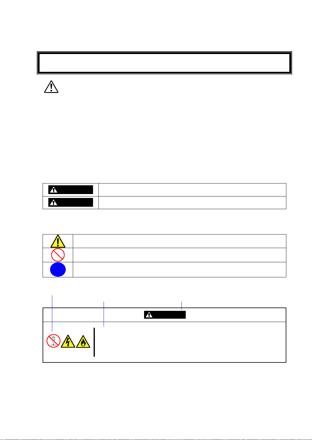
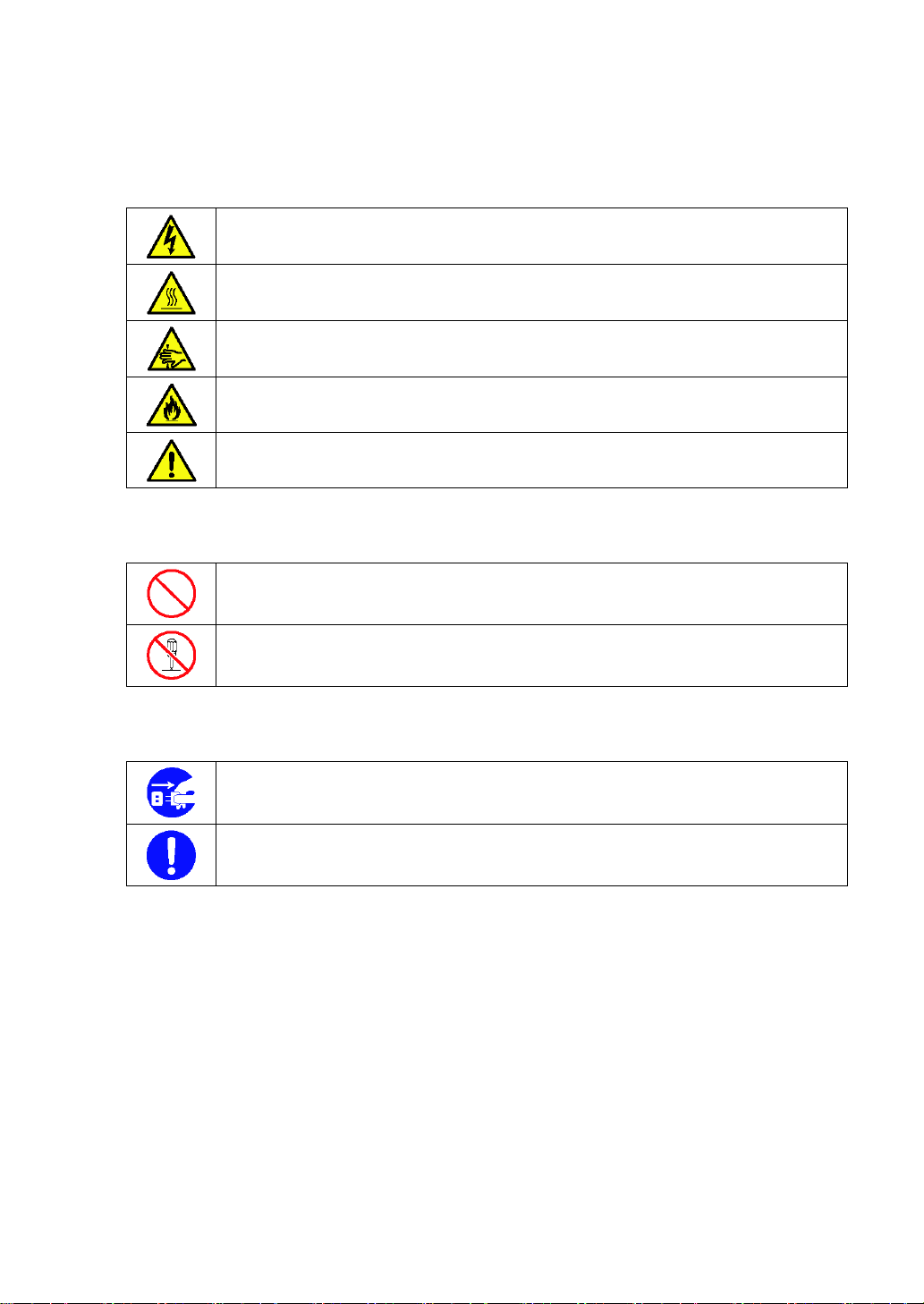
WARNING
Indicates the presence of a hazard that may result in death or serious
personal injury if the instruction is ignored.
CAUTION
Indicates the presence of a hazard that may cause minor personal injury,
including burns, or property damage if the instruction is ignored.
This symbol indicates the presence of a hazard if the instruction is ignored.
An image in the symbol illustrates the hazard type. (Attention)
This symbol indicates prohibited actions. An image in the symbol illustrates a
particular prohibited action. (Prohibited Action)
This symbol indicates mandatory actions. An image in the symbol illustrates a
mandatory action to avoid a particular hazard. (Mandatory Action)
Symbol to draw attention
Description of a danger
Term indicating a degree of danger
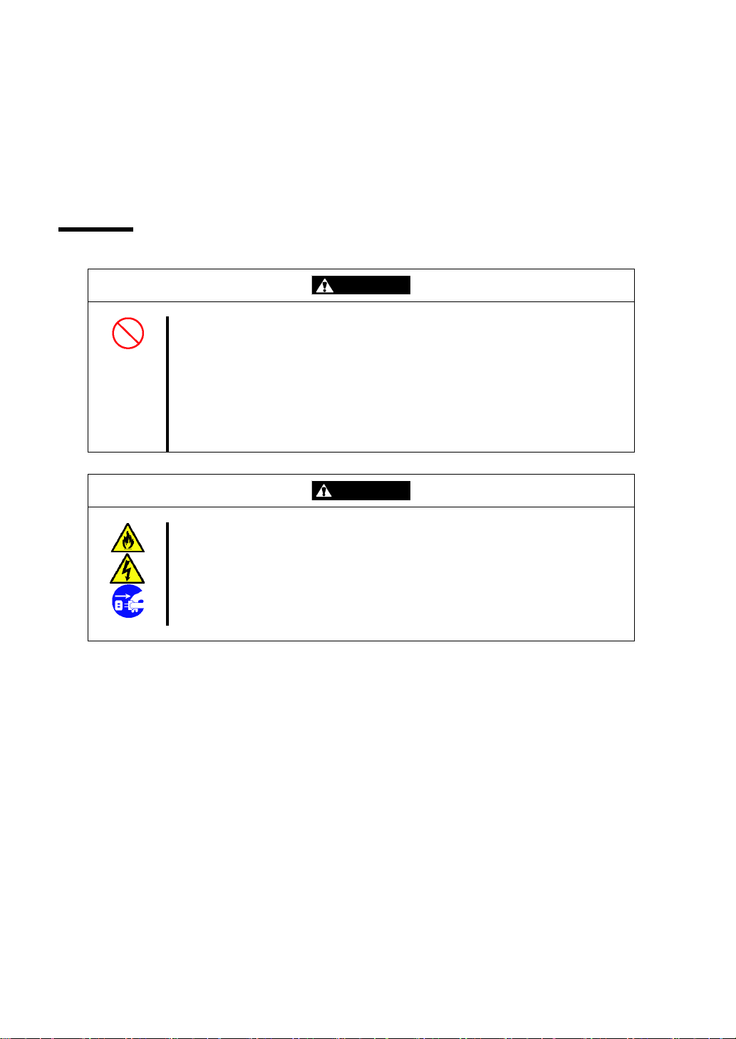
CAUTION
Do not disassemble, repair, or alter the server.
Never attempt to disassemble, repair, or alter the server on any occasion
other than described in this User's Guide. Failure to follow this instruction may
cause an electric shock or fire as well as malfunctions of the server.
Read this User's Guide and the User's Guide of the server before using the product.
Keep this User's Guide handy for quick reference when necessary.
Be sure to read this section carefully.
NOTES ON USE - Always read the Notes -
The following includes information necessary for proper and safe operation of the product.
SAFETY INDICATIONS
Follow the instructions in this manual for your safety when using the product.
In the User's Guide, "WARNING" or "CAUTION" is used to indicate a degree of danger. These terms
are defined as follows:
Precautions and notices against hazards are presented with one of the following three symbols. The
individual symbols are defined as follows:
(Example)
Symbols used in this User's Guide and warning labels are listed below.
- i -
Page 4
請於使用本產品前,閱讀本使用指南及伺服器的使用指南
WARNING
表示如不遵守該指示,所存在的危險可能導致死亡或嚴重個人傷害。
CAUTION
表示如不遵守該指示,所存在的危險可能導致次要的個人傷害,包含燒傷或
財產損失。
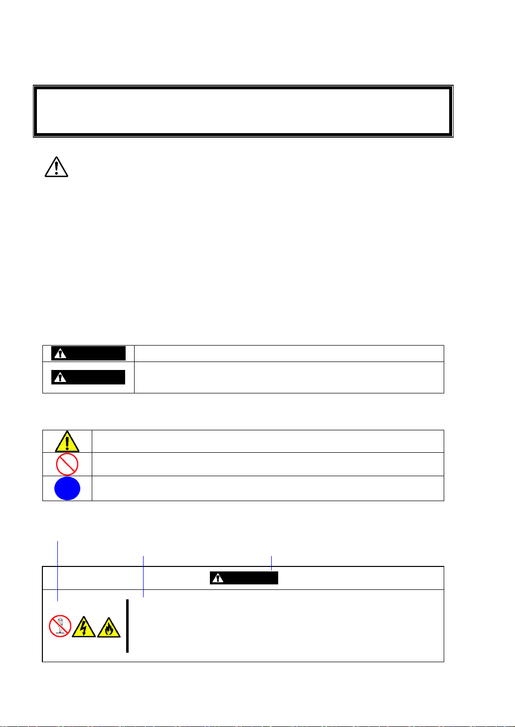
此符號表示如不遵守該指示可能存在的危險。符號中的圖案為危險內容。(注意)
此符號表示禁止行為。符號中的圖案為禁止行為內容。(禁止行為)
此符號表示強制行為。符號中的圖案為強制行為內容,以避免特殊的危險。(強制行為)
引起注意的符號
危險描述
表示危險程度名稱
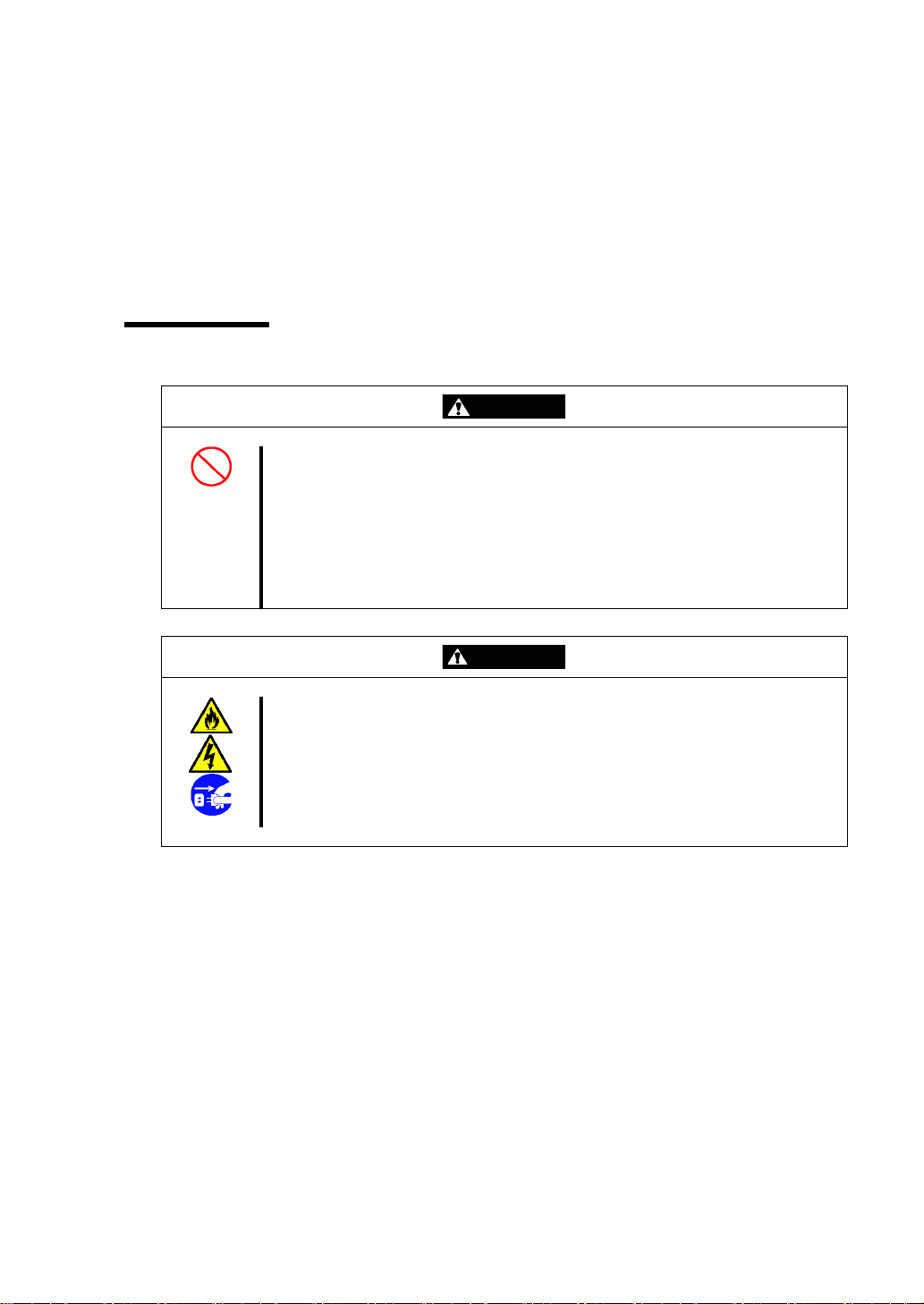
CAUTION
請勿自行拆卸、修理或改造本伺服器。
除本書記載的情況外,請勿嘗試自行拆卸、修理或改造本伺服器。否則可能引起
觸電或火災,以及導致伺服器無法正常動作。
請就近保存本使用指南,以便任何需要之時可快速參閱
請仔細閱讀本章節
使用注意事項 – 請經常閱讀此注意事項 -
以下包含正常及安全操作本產品的必要訊息。
安全指示
為了安全地使用本產品,請遵照本指南內的說明。
在使用指南中,使用“ 警告” 或“ 注意” 來表示危險的程度,項目定義如下:
危險的預防措施及注意事項為下列三種符號之一,個別符號的定義如下:
(範例)
- ii -
Page 5

本使用指南所使用的符號及警告標籤如下所列。
- iii -
Page 6
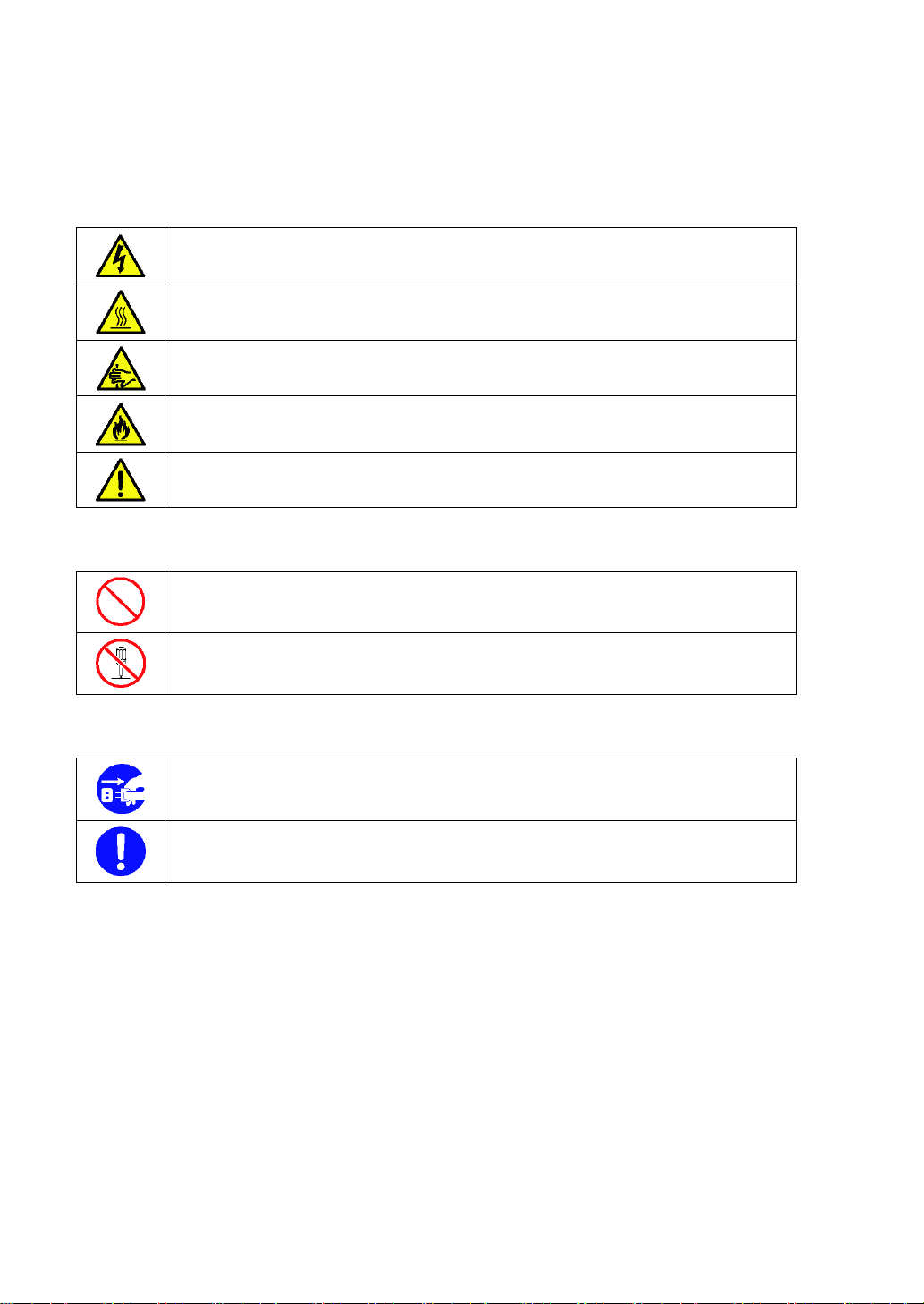
Indicates that improper use may cause an electric shock.
Indicates that improper use may cause personal injury.
Indicates that improper use may cause fingers to be caught.
Indicates that improper use may cause smoke or a fire.
Indicates a general notice or warning that cannot be specifically identified.
Indicates a general prohibited action that cannot be specifically identified.
Do not disassemble, repair, or modify the server. Otherwise, an electric shock or fire
may be caused.
Unplug the power cord of the server. Otherwise, an electric shock or fire may be
caused.
Indicates a mandatory action that cannot be specifically identified. Make sure to follow
the instruction.
Attentions
Prohibited Actions
Mandatory Action
- iv -
Page 7
注意
表示不當使用可能引起觸電。
表示不當使用可能造成人體傷害。
表示不當使用可能造成手指被夾住。
表示不當使用可能引起冒煙或火災。
表示非特定的一般性提醒或警告。
表示非特定的一般禁止。
請勿對伺服器進行拆卸、修理或改造,否則有觸電和發生火災的危險。
請將本設備的電源插頭從伺服器上拔下,否則有觸電和發生火災的危險。
對非特定的一般使用者的行為進行指示。請按照說明進行操作。
禁止行為
強制行為
- v -
Page 8
Safety Notes
WARNING
Do not use the server for services where critical high availability may directly
affect human lives.
The server is not intended to be used with or control facilities or devices
concerning human lives, including medical devices, nuclear facilities and
devices, aeronautics and space devices, transportation facilities and devices;
and facilities and devices requiring high reliability. NEC assumes no liability for
any accident resulting in personal injury, death, or property damage if the
server has been used in the above conditions.
CAUTION
Keep water or foreign matter away from the server.
Do not let any form of liquid (e.g., water) or foreign matter (e.g., pins or paper
clips) enter the server. Failure to follow this warning may cause an electric
shock, fire, or failure of the server. When such things accidentally enter the
server, immediately turn off the power and disconnect the power plug from the
outlet. Do not disassemble the server. Contact your service representative.
This section provides notes on using the product safely. Read this section carefully to ensure proper
and safe use of the product. For symbols, see "SAFETY INDICATIONS" provided earlier.
General
- vi -
Page 9
安全注意事項
WARNING
請勿使用本伺服器於需要高度可靠性及可能直接危及人命的操作上。
本產品請勿安裝於醫療設備、原子能設備、航空宇宙機器、運輸設備等會危及人
命以及需要高度可靠性的設備和機器上,也請勿使用本產品來控制這些機器。如
果將本產品用於這類系統的設備及機器,所造成的人身事故及財產損失等後果,
本公司概不負責。
CAUTION
請保持設備內不要進水和異物。
設備內請勿進入水、針、夾子等異物,否則可能引起火災和觸電。一旦有異物進
入,請立即關閉電源,將電源插頭從插座上拔下。請勿自行拆卸,並與經銷商或
維護服務公司聯繫。
本章節提供在安全使用上的注意事項。請仔細閱讀本章節,以確保正常及安全地使用本產品。
關於符號,請參閱前面的“ 安全指示” 。
一般注意事項
- vii -
Page 10
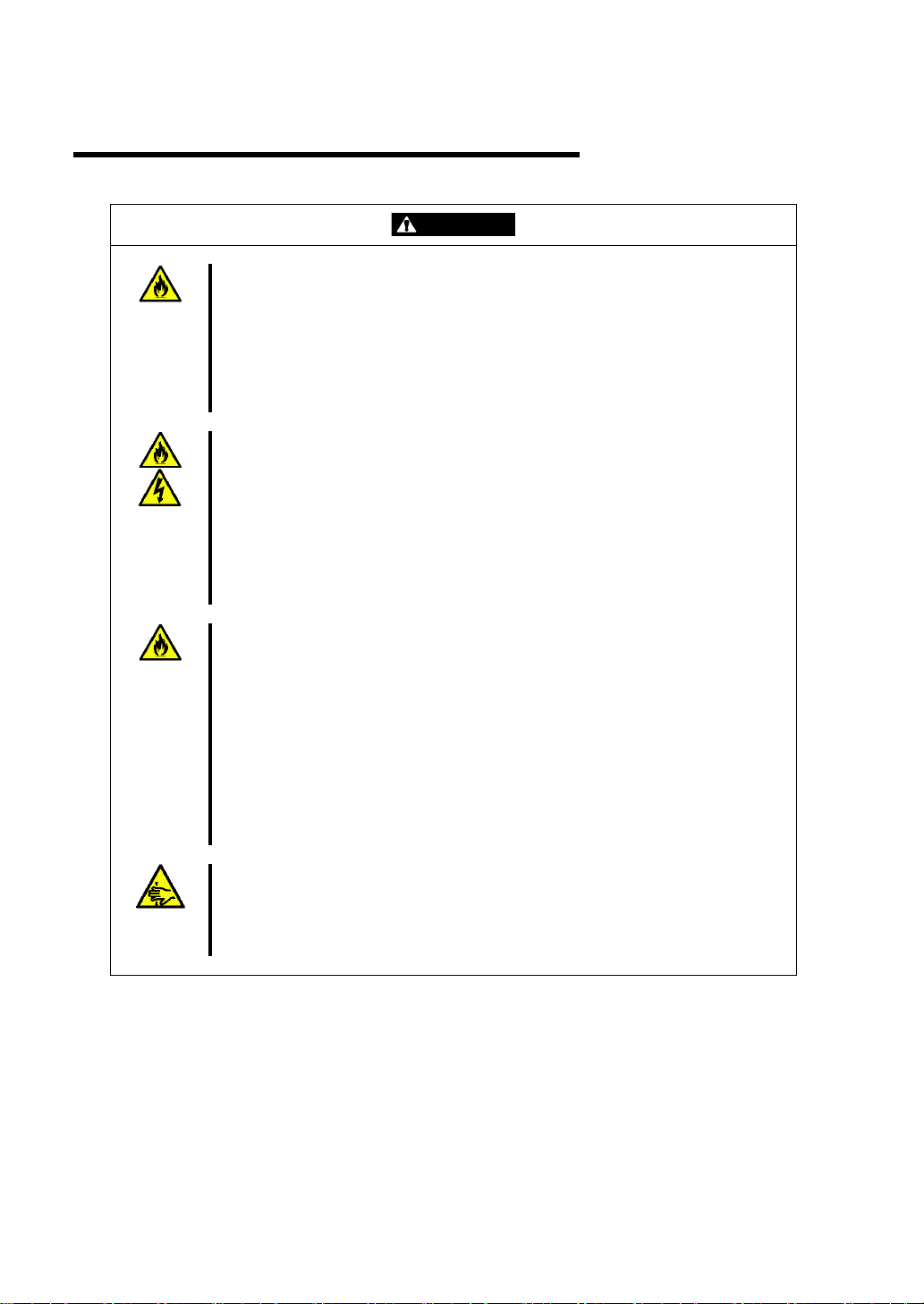
Installation, Relocation, Storage, and Connection
CAUTION
Do not install the server in a place other than specified.
Do not install the server in the following places or any place other than specified
in this manual. Failure to follow this instruction may cause a fire.
a dusty place
a humid place such as near a boiler
a place exposed to direct sunlight
an unstable place
Do not use the server in a place where corrosive gases exist.
Make sure not to locate or use the server in a place where corrosive gases
(sulfur dioxide, hydrogen sulfide, nitrogen dioxide, chlorine, ammonia, ozone,
etc) exist.
Also, do not locate it in an environment where the air (or dust) includes
components accelerating corrosion (e.g., sulfur, sodium chloride) or conductive
metals. There is a risk of a fire due to corrosion and shorts of the internal
printed circuit board.
Do not use an unauthorized interface cable.
Use only interface cables provided by NEC and locate a proper device and
connector before connecting a cable. Using an unauthorized cable or
connecting a cable to an improper destination may cause a short circuit,
resulting in a fire.
Also, observe the following notes on using and connecting an interface cable:
Do not use a damaged cable connector.
Do not use a damaged cable.
Do not step on the cable.
Do not place any object on the cable.
Do not use the server with loose cable connections.
Do not pinch your fingers in mechanical components.
Exercise caution so that your fingers are not caught between a door and
another mechanical part or cut during installation or removal of the product
in/from the server.
- viii -
Page 11
安裝,移動,保管及連接注意事項
CAUTION
請勿安裝或存放在未指定的場所。
請勿將本設備放置在如下場所,以及本書未指定的場所,否則可能引起火災。
灰塵較多的場所
熱水器旁等濕氣較高的場所
陽光直射的場所
不平穩的場所
請勿在有腐蝕性氣體的場所使用本設備。
請勿在有腐蝕性氣體(如二氧化硫、氫化硫、氮、氫、氨或臭氧等)存在的場所
使用或存放本產品。
還有,請勿將本產品安裝在灰塵較多或含有腐蝕性物質(如氯化鈉或硫磺)或含有過
量金屬碎末或傳導粒子等的地方。因為內部機板腐蝕或短路,可能引起火災的危
險。
請勿使用未指定的信號線。
請使用NEC指定的信號線,並在確認連接設備和介面後進行連接。使用未指定信
號線或連接錯誤等會造成短路、導致火災。
信號線的操作和連接,須遵守以下注意事項:
請勿使用任何損壞的信號線接頭。
請勿使用任何損壞的信號線。
請勿踩踏信號線。
請勿在信號線上載入物品。
信號線接鬆動時請勿使用。
請勿讓機械零件夾住您的手指。
請充分了解注意,您的手指並不會在介於門與其他機械部份間被夾住,或從伺服
器安裝或移動產品時被切斷。
- ix -
Page 12
Cleaning
WARNING
Do not disassemble, repair, or alter the server.
Never attempt to disassemble, repair, or alter the server on any occasion other
than described in this manual. Failure to follow this instruction may cause an
electric shock or fire as well as malfunctions of the server.
CAUTION
Make sure to complete device installation.
Always connect power cords and interface cables firmly. An incompletely
installed device may cause a contact failure, resulting in smoke or a fire.
WARNING
請勿自行拆卸、修理或改造本伺服器。
除本書記載的情況外,請勿嘗試自行拆卸、修理或改造本伺服器。否則可能引起
觸電或火災,以及導致伺服器無法正常動作。
CAUTION
確認安裝完畢。
電源線及信號線要穩固地連接妥當。不確實的安裝可能引起接觸不良,造成冒煙
或火災。
清潔注意事項
- x -
Page 13

Preface
IMPORTANT:
Items that are mandatory or require attention when using the server
NOTE:
Helpful and convenient piece of information
Thank you for purchasing the EM card. Installing the EM card in the EM card slot on the Blade
Enclosure (SIGMABLADE-M) provides the following management features. See [Basic Features] [Management Features] described later.
Power management
Cooling fan management
Chassis management in rack: Manages the names of rack, Blade Enclosure, and
information of modules in the Blade Enclosure
System monitoring: Monitors statuses of power supply unit, fan, and modules in Blade
Enclosure
External interfaces
In the Package
The carton contains various accessories as listed below. Make sure that you have everything. If you
find any component is missing, contact your service representative.
EM card ×1
CD-ROM containing document ×1
Precautions on Use ×1
Warranty ×1
NOTE: This warranty is available only for use in Japan.
Do not use it in any other country other than Japan.
Text Conventions
The following conventions are used throughout this User's Guide. For safety symbols, see
"SAFETY INDICATIONS" provided earlier.
- xi -
Page 14

For Proper Operation
Observe the following notes for successful operation of the product. Use of the product ignoring the
notes will cause malfunctions or failures of the server.
Clean the product on a regular basis. Regular cleaning proactively prevents various
failures of the server.
Transfer to Third Party
When you transfer (or sell) the product, make sure to provide this manual along with the product to
a third party.
Disposal
Dispose of the EM card according to all national laws and regulations.
- xii -
Page 15

Contents
NOTES ON USE - Always read the Notes - ................................................. i
使用注意事項
–
請經常閱讀此注意事項
- ..................................................... ii
Safety Notes ......................................................................................................................vi
General ..........................................................................................................................vi
安全注意事項
一般注意事項
................................................................................................................. vii
............................................................................................................. vii
Installation, Relocation, Storage, and Connection ..................................................... viii
安裝,移動,保管及連接注意事項
...........................................................................ix
Cleaning ......................................................................................................................... x
清潔注意事項
................................................................................................................ x
Preface ...............................................................................................................................xi
In the Package ...................................................................................................................xi
Text Conventions ...............................................................................................................xi
For Proper Operation ....................................................................................................... xii
Transfer to Third Party .................................................................................................... xii
Disposal ........................................................................................................................... xii
Contents .......................................................................................................................... xiii
Chapter 1 Names and Functions of Components ............................................ 1
EM Card ............................................................................................................................. 1
LED Indication ................................................................................................................... 3
STATUS LED ................................................................................................................. 3
ACTIVE LED ................................................................................................................ 4
ID LED ........................................................................................................................... 4
LINK/ACT LED ............................................................................................................. 4
SPEED LED ................................................................................................................... 4
Basic Features .................................................................................................................... 5
Management Feature ...................................................................................................... 5
Bridge Function ............................................................................................................ 10
SNMP Agent ................................................................................................................. 10
Duplex EM ................................................................................................................... 10
Chapter 2 Installation/Removal of EM Card ................................................... 11
Safety Notes ..................................................................................................................... 12
Preparation for Installation/Removal ............................................................................... 12
Installation/Removal Procedure ....................................................................................... 13
Connectors on Rear Panel of Blade Enclosure ................................................................. 16
- xiii -
Page 16

Chapter 3 Using Command Line Console Feature ........................................ 19
Connection ....................................................................................................................... 19
Connecting with Management Port ............................................................................. 19
Login and Basic Operations ............................................................................................ 21
Command Input ........................................................................................................... 21
Login / Logout ............................................................................................................. 22
Initial Setup ..................................................................................................................... 23
Basic Setup .................................................................................................................. 23
Basic Setup in Configuration File................................................................................ 25
Backup/Restore of Configuration File ......................................................................... 37
Updating Firmware .......................................................................................................... 38
Updating EM Firmware ............................................................................................... 38
Updating SIGMABLADE Monitor Firmware ............................................................. 41
Configuration File............................................................................................................ 44
Rack ............................................................................................................................. 44
Blade Enclosure ........................................................................................................... 45
CPU Blade ................................................................................................................... 46
Switch Module ............................................................................................................. 46
EM Card ...................................................................................................................... 47
EM Control .................................................................................................................. 48
SIGMABLADE Monitor ............................................................................................. 50
SNMP .......................................................................................................................... 51
Linkage with NEC DianaScope ................................................................................... 53
UPS Management ........................................................................................................ 55
Command Reference ....................................................................................................... 58
Chapter 4 Using Web Console Feature .......................................................... 75
Connection ....................................................................................................................... 75
Login and Basic Operation .............................................................................................. 76
Login/Logout ............................................................................................................... 76
Screen Layout .............................................................................................................. 78
Basic Operations .......................................................................................................... 79
Displaying System Status ................................................................................................ 80
System Status List ....................................................................................................... 80
CPU Blades ................................................................................................................. 81
Switch Modules ........................................................................................................... 83
Blade Enclosure ........................................................................................................... 85
EM Card ...................................................................................................................... 86
Power Unit ................................................................................................................... 87
FAN Unit ..................................................................................................................... 88
UPS .............................................................................................................................. 89
- xiv -
Page 17

Detailed System Information ............................................................................................ 90
CPU Blade .................................................................................................................... 90
Switch Module ............................................................................................................. 92
Blade Enclosure ............................................................................................................ 94
EM Card ....................................................................................................................... 96
Power Units .................................................................................................................. 98
Fan Units .................................................................................................................... 100
UPS............................................................................................................................. 102
Rack Information ........................................................................................................ 104
Power Information ...................................................................................................... 109
Configuration ................................................................................................................. 117
Edit Configuration ...................................................................................................... 117
Backup Configuration ................................................................................................ 138
Restore Configuration ................................................................................................ 139
Password Configuration ............................................................................................. 141
Log Management ........................................................................................................ 144
Update Firmware ........................................................................................................ 145
Chapter 5 SIGMABLADE Monitor ................................................................. 149
Components of SIGMABLADE Monitor ...................................................................... 149
LED Indication ............................................................................................................... 149
Using SIGMABLADE Monitor ..................................................................................... 150
Top Menu ................................................................................................................... 150
Main Menu ................................................................................................................. 150
Displaying System Information .................................................................................. 152
Displaying CPU Blade Information ........................................................................... 155
Displaying Switch Module Information ..................................................................... 157
System Setup .............................................................................................................. 158
Collecting Logs .......................................................................................................... 170
Setting OSD (On Screen Display) .............................................................................. 172
Diagnosis by SIGMABLADE Monitor .......................................................................... 176
Diagnostic Process ..................................................................................................... 176
Indication during Diagnosis ....................................................................................... 176
Indication of Diagnosis End ....................................................................................... 177
Indication of EM Card Error .......................................................................................... 178
Switchover between KVM and DVD ......................................................................... 178
- xv -
Page 18

Chapter 6 Using OSD (On Screen Display) Feature .................................... 179
OSD Menu Mode........................................................................................................... 180
Activating OSD Menu Mode ..................................................................................... 181
Operation in OSD Menu Mode.................................................................................. 182
OSD Simple Mode......................................................................................................... 201
Activating OSD Simple Mode ................................................................................... 201
Operation in OSD Simple Mode ............................................................................... 202
Server Name Resident Mode ......................................................................................... 203
Activating Server Name Resident Mode ................................................................... 203
Chapter 7 Troubleshooting ........................................................................... 205
LED Indication .............................................................................................................. 205
Error Message on SIGMABLADE Monitor .................................................................. 205
Collecting Error Logs .................................................................................................... 207
Overview ................................................................................................................... 207
Collection using Web Console ................................................................................... 207
Collection using SIGMABLADE Monitor ................................................................ 207
Collection using Command Line Console ................................................................. 208
Collection using NEC ESMPRO Manager ................................................................ 208
Others ............................................................................................................................ 209
- xvi -
Page 19

(This page is intentionally left blank.)
- xvii -
Page 20

Page 21
Chapter 1
Names and Functions of Components
Names and functions of the components are shown below:
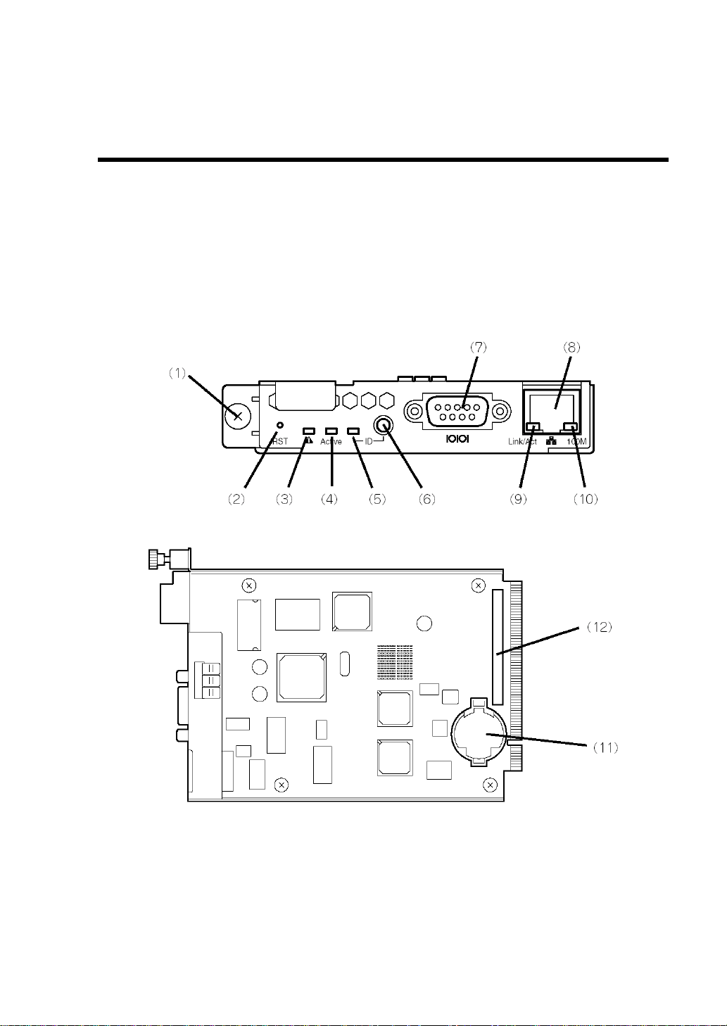
EM Card
Front View
Internal View
- 1 -
Page 22

(1)
Fixing screw
Used to secure the EM card to the Blade Enclosure.
(2)
RESET switch
Used to reset the EM card.
(3)
STATUS LED (green/amber)
Indicates the status of the EM card. See "LED Indication" for details.
(4)
ACTIVE LED (green)
This LED is lit when the EM card is specified as the active EM.
(5)
ID LED (blue)
Used to identify the device. For details, see "LED Indication" described later.
(6)
ID switch
Used to turn on or off the ID LED. When pressed, the management PC is notified that the
target EM card is identified.
(7)
Serial port
Used as a management port. Management of the EM card is available while the EM card is
active. This port is available only while the door of the SIGMABLADE monitor is open, and is
mainly used to temporarily connect a terminal device.
(8)
Management LAN interface
Used as a management LAN port. Do not use this LAN port for any other use. Use the
EM1/EM2 port at the rear of the Blade Enclosure instead.
(9)
LINK/ACT LED (green)
Indicates the LAN access status. For details, see "LED Indication" described later.
(10)
SPEED LED (amber)
Indicates the transfer rate of the LAN port. For details, see "LED Indication" described later.
(11)
Lithium battery
(12)
MAC (Media Access Control) address label
Shows the network-specific MAC address used by the EM card.
Note this address when installing or removing the EM card.
- 2 -
Page 23

STATUS LED
condition
Meaning
Action
Continuous green
The EM card is working
normally.
–
Flashing in amber
Reset process is in progress.
Wait for a moment. When the reset
process completes, the LED turns green.
An error occurred in the EM
card.
Replace the EM card according to the
installation/removal procedure described
later.
STATUS LED condition
Meaning
Action
EM card in slot
EM1
EM card in slot
EM2
Continuous green
Flashing in green
The EM card in slot EM1 is
operating as an active card.
The EM card in slot EM2 is
operating as a standby card.
Wait for a moment.
When the reset process
completes, the LED
turns green.
Flashing in green
Continuous green
The EM card in slot EM1 is
operating as a standby card.
The EM card in slot EM2 is
operating as an active card.
Flashing in amber
Flashing in amber
Reset process is in progress.
Wait for a moment.
When the reset process
completes, the LED
turns green.
Flashing in amber
Continuous green
An error occurred on the EM
card in slot EM1.
Replace the failed EM
card according to the
installation/removal
procedure described
later.
Continuous green
Flashing in amber
An error occurred on the EM
card in slot EM2.
LED Indication
Shown below are LED indications and their explanations.
STATUS LED
The table below shows the indications of the STATUS LED and the recommended actions:
When a single EM card is installed (in EM card slot EM1 or EM2)
When two EM cards are installed (in EM card slots EM1 and EM2)
- 3 -
Page 24

ACTIVE LED
This LED turns green when the EM card is specified as an "Active" card. If the EM card is specified
as a "Standby" card, this LED does not turn on.
ID LED
The ID LED of the EM card which is activated by the ID switch or a software command turns blue.
LINK/ACT LED
This LED turns green when the LAN port is connected to the network. It flashes green while
performing data transmission.
SPEED LED
The LAN port supports 100BASE-TX and 10BASE-T interface. This LED turns amber when the
network port is linking at 100Mbps and goes off when linking at 10Mbps.
NOTE: For the names and LED indications of the SIGMABLADE
monitor, see Chapter 5.
- 4 -
Page 25

Basic Features
This section describes the basic features of the EM card.
Management Feature
The management features of the EM card are as follows:
Power Management
The EM card manages DC output of power unit(s) in the Blade Enclosure. When AC power is
supplied to the Blade Enclosure, the EM card starts operating. If two or more power units are
installed in the Blade Enclosure and they are working normally, the EM card turns on the DC output
of two of them.
NOTE: For the third and subsequent power units, DC output is turned
on/off as needed.
The EM card manages the power consumption of the entire system.
The maximum power consumption of the entire system varies depending on the power capacity
supplied to the system and the configuration of power units (including the number and type of
units).
The EM card manages the power consumption of each of the modules of the system so that its
maximum power consumption is maintained within a certain value (referred to as "ceiling control").
One of the following three upper limit values is used for ceiling control:
(A) Upper limit determined by the type and number of power supply units and the input voltage.
(B) If a UPS is managed by the EM card, the EM card calculates the upper limit based on the type
of UPS connected.
(C) Upper limit specified for input voltage regardless of the configuration of power units or use of
UPS Manager. See "Configuration File" in Chapter 3 and "Configuration" in Chapter 4 for
details.
The EM card uses the lowest value among (A), (B), and (C) as the upper limit value and performs
ceiling control of system power consumption.
You can select a power redundancy mode (N+N redundant or N+1 redundant) and a power control
policy (CPU performance, "maintain redundancy," or "recover redundancy") for the power
management policies of the EM card.
- 5 -
Page 26

There are two power redundancy modes, N+N redundant and N+1 redundant.
– In the N+N redundant mode, each power unit is divided into two groups to configure
the redundant power supply system. If a power supply in a group fails, the power of the
other group can maintain system operation.
– In the N+1 redundant mode, power units are not grouped but each power unit is
controlled individually. Using a power supply in addition to the number of power units
required for normal system operation enables power system redundancy.
The power control policy includes three modes, CPU performance, "maintain
redundancy," and "recover redundancy."
– The CPU performance mode makes the EM card prioritize performance of CPU blades.
In this mode, if the EM card cannot accept a new power request from a CPU blade
while maintaining power redundancy, the EM card releases the power redundant
configuration and permits the new power request from the CPU blade. (If a power unit
fails during operation under the release of the power redundant configuration, then the
system may be forcibly shut down.)
– The "maintain redundancy" mode makes the EM card accept a new power request from
a CPU bladeonly if the power redundancy can be maintained. If the EM card cannot
accept a new power request from a CPU blade while maintaining power redundancy,
the EM card denies the request. In the "maintain redundancy" mode, no emergency
measures are taken if the power redundancy is lost due to a failure of a power unit.
(When a power unit fails with no power redundancy status, the system may be forcibly
shut down.)
– The "recover redundancy" mode makes the EM card accept a new power request from
a CPU blade while maintaining power redundancy by limiting the performance of CPU
blades to reduce the power consumption in the event of a power unit failure.
(Depending on the operation of CPU blades, the EM card may not be able to reduce the
power consumption to allow the power redundancy to be recovered.)
When a switch module inserted into a switch module slot issues a power-on request, the EM card
checks the power consumption of the switch module and turns it on if it is within the maximum
power consumption management described above.
When a CPU blade inserted into a CPU blade slot requests power, the EM card permits it if the
power consumption is possible within the maximum power consumption management described
above.
NOTE: When a CPU blade issues a power-on request to the EM card,
the request is denied if the EM card determines there is insufficient
power due to an event such as a power shortage.
- 6 -
Page 27

UPS Management
The EM card monitors the status of UPS supplying power to the Blade Enclosure. In addition, the
EM card shuts down CPU blades if AC power to the UPS is interrupted.
NOTES:
Check that the UPS has enough capacity to supply the power
required for the entire system. The EM card calculates the
maximum capacity of power supplied by the UPS to reflect the
value in the maximum power consumption management described
above. If the UPS has a low power supply capacity, some CPU
blades may not be turned on.
When using Windows 2003 Server, "Logging on to the system is not
required to shut down the system" should be enabled in the Security
Policy tab.
The EM card automatically detects the following UPS’s:
For 200 VAC:
5000VA UPS [N8142-24A] and 8000VA-UPS [N8142-25]
For 100 VAC:
3000VA-UPS [N8142-11B] and 1500VA-UPS [N8142-23A]
As described above, in the event that power to the UPS is
interrupted, CPU blades may be shut down automatically. However,
after power to the UPS is restored, the CPU blades will not start
automatically. You need to power on the CPU blades manually.
Cooling Fan Management
When the CPU blade is powered on, the necessary amount of cooling air changes according to the
temperature. The EM card determines the optimal rotation speed of the fan according to the number
of installed fan units.
NOTE: Depending on the number of installed fan units and CPU
blades and their installation locations, when the EM card determines
that the cooling capacity is insufficient, it may not permit a CPU blade
to power-on. In this case, check that the fan units and CPU blades are
properly installed.
- 7 -
Page 28

Interface Management between CPU Blade and Switch Module
If the CPU blade is incorrectly connected to the switch module, it will be damaged. To prevent this,
the EM card checks the interface connection between them. If the interface connection is not correct,
the EM card suppresses the power-on of the relevant CPU blade and switch module or disables the
connection port.
NOTE: For more information on the connection between the CPU
blade and switch module in the Blade Enclosure, refer to the User's
Guide of the switch module.
Chassis Information Management
The EM card manages the names of the rack, Blade Enclosure, CPU blades, and switch modules.
Except for CPU blade names, they are specified in a configuration file.
NOTE: The CPU blade name can be obtained from the CPU blade.
- 8 -
Page 29

Blade Enclosure Inter Connect
If more than one Blade Enclosure (SIGMABLADE-M) is mounted in a single rack, connect a LAN
cable (straight) to the LOWER port of the topmost Blade Enclosure and the UPPER port of the
Blade Enclosure installed beneath it to allow the EM cards of the Blade Enclosures to share the rack
name and its unique ID.
The EM cards can read the status information of the Blade Enclosures and display the information
on the Web console.
The Rack Information screen on the Web console has a link for each connected Blade Enclosure.
When the same user name and password are set for the Web consoles, you can automatically log in
to any Web console through the link to the Web console.
See Chaper 4 for details of the Web console.
IMPORTANT:
To use the Blade Enclosure inter connect, EM card N8405-019A
must be installed.
For the Blade Enclosure inter connect, use LAN cables (straight) as
short as possible. LAN cables of three meters or less are
recommended.
Do not connect a LAN cable to the UPPER port of the topmost
Blade Enclosure and the LOWER port of the Blade Enclosure
installed beneath it.
NOTES:
Check that LAN cables are connected correctly. Each of the EM
cards recognizes the positional relationship among the Blade
Enclosures in the rack depending on the cable connections to the
UPPER and LOWER ports on the Blade Enclosures. Incorrect cable
connections prevent the EM cards from recognizing the positional
relationship among the Blade Enclosures properly.
Up to six Blade Enclosures can use the Blade Enclosure inter
connect.
- 9 -
Page 30

Bridge Function
The EM card bridges packets from the EM1/EM2 port at the rear of the Blade Enclosure to the
internal network. It enables network communication between the management unit of the CPU
blades and switch modules in the Blade Enclosure (e.g., EXPRESSSCOPE Engine) and external
devices.
NOTE: When bridging, the EM card executes port filtering to prevent
unnecessary packets from flowing to the network.
The port number 49623 is used exclusively by the EM card and cannot
be used for any other purpose.
SNMP Agent
SNMP is a protocol used to communicate management data among network devices.
The administrator of the EM card can use SNMP to monitor the operating status of the EM card and
the blade system (Blade Enclosure, fan units, or power units) which the EM card manages.
Registering community name and SNMP trap message destination are specified in a configuration
file.
Duplex EM
Installing two EM cards in the EM1 and EM2 slots enables the duplexed configuration. In the
duplexed configuration, one of the EM cards is an active EM, and as the other is a standby EM card.
The cards are connected with an internal serial interface to transmit/receive information
synchronously.
When an active EM fails or when the switchover command is executed, it is changed to a standby
EM after the system is rebooted. The previous standby EM then becomes the active EM.
IMPORTANT:
In the duplexed configuration, the firmware revision of the EM
cards should be the same.
To use the Blade Enclosure inter connect in the duplexed
configuration, EM card N8405-019A must be installed. If the Blade
Enclosure inter connect is not used in the duplexed configuration,
both N8405-019 and N8405-019A can be used in the Blade
Enclosures. The Blade Enclosure inter connect can be used without
the duplexed configuration.
NOTE: When the switchover command is executed, the bridge feature
is temporarily stopped, and the management LAN interface may be
temporarily disconnected.
- 10 -
Page 31

Chapter 2
Installation/Removal of EM Card
Two EM cards can be installed in the slots located at the front of the Blade Enclosure.
This section describes how to install the EM card in the Blade Enclosure and provides notes on
using the EM card.
IMPORTANT:
The EM card may be installed or removed by any user. However,
NEC does not assume any liability for damage to devices or the
server or malfunctions of the server resulting from installation by
the user. NEC recommends you ask your service representative for
assistance to install or remove the EM card.
Make sure to use only cables authorized by NEC. Repair costs of
the server due to malfunctions, failures, or damage resulting from
using unauthorized cables will be charged even within the warranty
period.
- 11 -
Page 32

WARNING
Observe the following instructions to use the server safely. Failure to follow
these instructions may result in death or serious personal injury. See pages i to
v for details.
Do not disassemble, repair, or alter the server.
Unplug the power cord before working with the server.
CAUTION
Observe the following instructions to use the server safely. Failure to follow
these instructions may cause a fire, personal injury, or property damage. See
pages i to v for details.
Make sure to complete installation.
Do not pinch your finger(s) in components.
Safety Notes
Observe the following notes to install or remove the EM card safely and properly:
Keep the component in an anti-static bag until you are ready to install it in the Blade
Enclosure.
Hold the component by its edges to avoid touching any terminals or parts.
To store or carry the component, place it in an anti-static bag.
Preparation for Installation/Removal
A Phillips screwdriver is required.
If the EM cards are not in a redundant configuration prior to replacement, the configuration data
will be lost. You must reconfigure the EM card after replacement.
NOTE: It is recommended to make a backup copy of the configuration
data of the EM card.
The configuration file name is as follows:
File name: /var/nvdata/rw_poem.conf
For information on the backup/restore procedure, see "Backup/Restore
of Configuration File" described later.
- 12 -
Page 33

CAUTION
Observe the following instructions to use the server safely. Failure to follow
these instructions may cause a fire, personal injury, or property damage. See
pages i to v for details.
Make sure to complete installation.
Do not pinch your finger(s) in components.
Thumbnut
Installation/Removal Procedure
Install or remove the EM card in the following procedure.
Installation
1. Prepare for installation according to "Preparation for Installation/Removal."
2. Loosen the thumbnut on the SIGMABLADE monitor and open the cover.
- 13 -
Page 34

Thumbnut
Handle
3. Locate the slot to install the EM card. Insert the EM card into the slot while pushing the
handle.
NOTE: When removing the EM card, hold the handle and pull the EM
card out from the slot.
4. Secure the EM card to the Blade Enclosure by tightening the thumbnut located at the left
end of the card.
- 14 -
Page 35

5. Close the cover of the SIGMABLADE monitor and secure it with the thumbnut.
Removal
The removal procedure is the reverse of the installation procedure.
NOTE: It is recommended to make a backup copy of the configuration
data of the EM card.
For information on the backup/restore procedure, see "Backup/Restore
of Configuration File" described later.
IMPORTANT: As long as
– no EM card is installed, or
– the ACTIVE LED of the EM card(s) is not lit after the EM card is
installed,
do not install or uninstall CPU blades, switch modules, fan units, power
units, and power cords.
- 15 -
Page 36

(1)
UPPER port
Used when more than one Blade Enclosure is mounted in a rack and the Blade Enclosure
inter connect is used.
Connected to the LOWER port of the Blade Enclosure installed above it with a LAN cable
(straight). If the Blade Enclosure is installed at the top of the rack, the UPPER port is not used.
(2)
LOWER port
Used when more than one Blade Enclosure is mounted in a rack and the Blade Enclosure
inter connect is used.
Connected to the UPPER port of the Blade Enclosure installed beneath it with a LAN cable
(straight). If the Blade Enclosure is installed at the bottom of the rack, the LOWER port is not
used.
(3)
EM1 port
Management LAN interface for the EM card installed in EM card slot EM1.
Manages the EM card and manages CPU blades via EM card.
(4)
EM2 port
Management LAN interface for the EM card installed in EM card slot EM2.
Manages the EM card and manages CPU blades via EM card.
(5)
EXT1 port
Used for UPS management.
Connected to the SNMP card in a UPS with a LAN cable.
(6)
EXT2 port
Used for UPS management.
Connected to the SNMP card in another UPS with a LAN cable.
(7)
Serial port
Not used in normal operation.
(8)
Monitor connector
Connector for the display unit. Used by SIGMABLADE monitor and OSD function.
Connectors on Rear Panel of Blade Enclosure
The connectors on the rear panel of the Blade Enclosure are shown below:
Connectors on Rear Panel of Blade Enclosure
- 16 -
Page 37

(9)
Keyboard connector
Connector for the PS/2 keyboard. Used by SIGMABLADE monitor and OSD function.
(10)
Mouse connector
Connector for the PS/2 mouse. Used by SIGMABLADE monitor and OSD function.
IMPORTANT:
EM card N8405-019 does not support the Blade Enclosure inter
connect feature. To use this feature, purchase EM card
N8405-019A.
The UPPER and LOWER ports on the Blade Enclosure are
exclusively used for the Blade Enclosure inter connect. Do not
connect any other devices to these ports.
The EXT1 and EXT2 ports are exclusively used by the EM card for
UPS management. Do not connect any other devices to these ports.
NOTE: Link local address 169.254.0.0/16 is used for the Blade
Enclosure inter connect.
- 17 -
Page 38

(This page is intentionally left blank.)
- 18 -
Page 39

Chapter 3
Using Command Line Console Feature
This section explains the command line console feature.
Connection
To use the command line console feature, a management console (e.g., personal computer) must be
connected to the management port.
Connecting with Management Port
The EM card has two interfaces for the management port, the serial port and the network port
(100Bate-Tx/10Base-T).
IMPORTANT: To connect to the management network, use the"EM1
" and "EM2 " connectors on the rear of the Blade Enclosure.
NOTE: Connect to the management port when performing initial setup
or maintenance of the EM card.
Connection via Serial Port
Connect a management console (e.g., personal computer) to the serial port. When you use the EM
card for the first time, the management console must be connected.
The management console must have communication software that conforms to VT-100.
Configure the communication software as follows:
– Baud rate: 115200bps
– Data length: 8 bits
– Parity: None
– Stop bit: 1
– Flow control: None
IMPORTANT: A leased line cannot be connected to the serial port
directly.
- 19 -
Page 40

Connection via Network Port
Use TELNET or SSH (password authentication) to connect via the network. To login to the EM card
via TELNET/SSH, use the assigned IP address.
NOTE: The default IP address is 192.168.1.8/24. You may connect
with this IP address and then change it.However, the connection to the
network is lost when you change the IP address. The SIGMABLADE
monitor described in Section 5 also allows you to change the IP
address.
IMPORTANT: To connect to the management network, use the "EM1
" and "EM2 " connectors on the rear of the Blade Enclosure.
- 20 -
Page 41

Login and Basic Operations
This section describes how to input a command, login, logout, and change the password.
Command Input
The command input is described below.
About Command
The EM card accepts commands sent from the CLI (Command Line Interface). When the CLI is
ready for command input, it displays a "$" sign as a prompt at the beginning of the line.
A command should be entered following the command prompt displayed on the screen. For
commands that need parameters, those parameters should be separated with spaces.
Commands should be entered in 1-byte (half-size) alphanumeric and symbol or their combination.
Up to 255 characters can be accepted for one command.
Error Messages during Command Input
When the command is incorrect, an error message appears.
- 21 -
Page 42

Login / Logout
This section describes how to log in or log out of the EM card.
Login
When the EM card is accessed from the local console connected to the serial port or from the
computer connected to the management port, login authentication is executed.
Enter the login user name and login password.
The login user name is "admin". The shipping default password is "admin".
----------------------------------------------------------------em login: admin
Password:
...............
-----------------------------------------------------------------
IMPORTANT: For security, change the default password.
Logout
Use the "exit" command to log out.
Shown below is an example of how to log out by entering the "exit" command from the local
console connected to the serial port.
<Example>
----------------------------------------------------------------$ exit
login:
-----------------------------------------------------------------
NOTE: If you log out from a remote console connected via TELNET,
the TELNET connection will be disconnected. Accordingly, the prompt
"login:" will not be displayed.
Change Password
To change the password, use the "changepasswd" command.
Shown below is an example of changing the default password "admin" to "p@s$wD":
<Example>
----------------------------------------------------------------$ changepasswd admin p@s$wD
-----------------------------------------------------------------
- 22 -
Page 43

Initial Setup
This section describes the setup steps necessary to use the EM card.
Basic Setup
This section describes the setting of date, time, and IP address for remote control.
Setting Date and Time
The EM card incorporates a calendar clock equipped with a backup battery.
Use the "setdate" command to set the current date and time.
Shown below is an example of setting the date and time to 9:10:11 am on July 8, 2006:
<Example>
----------------------------------------------------------------$ setdate 2006/07/08 09:10:11
-----------------------------------------------------------------
To check the date and time, use the "setdate" command with no argument.
Shown below is an example showing the current date and time is 9:10:20 on July 8, 2006:
<Example>
----------------------------------------------------------------$ setdate
2006/07/08 09:10:20
-----------------------------------------------------------------
- 23 -
Page 44

Assigning the IP Address for Remote Control
To access the EM card from the remote console via Telnet, you must specify an IP address. The
default IP address is 192.168.1.8/24.
NOTE: This setting is effective for the EM1/EM2 ports on the rear of
the Blade Enclosure.
To change the default IP address, access the EM card from the remote console by using the default
IP address, or from the local console connected to the serial port.
Specify an IP address in the configuration file.
NOTE: You can also use [SIGMABLADE Monitor] menu described
in Chapter 5 to specify an IP address. In addition, you can use the Web
console described in Chapter 4 to change an IP address. In either case,
the new data is saved in the configuration file.
Use the "showemip" command to confirm the setting.
<Example>
----------------------------------------------------------------$ showemip
192.168.1.8
-----------------------------------------------------------------
- 24 -
Page 45

Basic Setup in Configuration File
This section describes the basic setup of the configuration file.
Overview
A dedicated configuration file (in text format) is used to configure the EM card. To edit the
configuration file, use the "vi" command.
File name: /var/nvdata/rw_poem.conf
NOTE: A file that is created or edited on another computer can be
transferred via FTP. In this case, use a character code "EUC," and line
feed code "LF" in the file.
The following format is used in the configuration file:
----------------------------------------------------------------[<section-name>]
<item-name> = <set-value>
-----------------------------------------------------------------
When a character string is used for <set-value>, the character string must be enclosed with double
quotation marks.
NOTE: A line containing only space characters is ignored.
IP Address of EM Card
The two EM cards installed in the Blade Enclosure use four IP addresses in total. These addresses
are classified into two types, "Fixed IP" is determined by the installation slot of the EM card, and
"Floating IP" is used by the active EM card regardless of the installation slot.
The last bit of "Fixed IP" corresponds to the installation slot.
The last bit of "Floating IP" is defined as "0" for the active EM card and "1" for the standby EM
card.
- 25 -
Page 46

NOTE: The IP address of the EM card is classified by the last two bits
as shown below:
00b: "Floating IP" that an active EM uses.
01b: "Floating IP" that a standby EM uses.
10b: "Fixed IP" of EM card installed in slot EM1.
11b: "Fixed IP" of EM card installed in slot EM2.
Default settings are shown below:
"Floating IP" of active EM: 192.168.1.8/24
"Floating IP" of standby EM: 192.168.1.9/24
"Fixed IP" of EM card in slot EM1: 192.168.1.10/24
"Fixed IP" of EM card in slot EM2: 192.168.1.11/24
Write the configuration file in the format as shown below:
----------------------------------------------------------------[RW_POEM_SECTION]
CFG_EM_IP = <IP Address>
CFG_EM_NETMASK = <Subnet Mask>
CFG_EM_GATEWAY = <Default Gateway>
-----------------------------------------------------------------
<IP Address>: Floating IP address that the active EM uses.
<Subnet Mask>: Subnet mask
<Default Gateway>: Default gateway
The above addresses must be specified with decimal numbers and periods such as
XXX.XXX.XXX.XXX (XXX: between 0 and 255).
IMPORTANT: If only one EM card is installed, four IP addresses are
reserved for it. Make sure that these IP addresses do not overlap with
the IP addresses of other devices.
NOTE: Did you specify a multiple of 4 for the last digit of <IP
Address>? If not, the EM card defines the last two bits as "00b."
<Example>
----------------------------------------------------------------[RW_POEM_SECTION]
CFG_EM_IP = 192.168.100.16
CFG_EM_NETMASK = 255.255.255.0
CFG_EM_GATEWAY = 192.168.100.254
-----------------------------------------------------------------
- 26 -
Page 47

DHCP
The IP addresses of management I/F of CPU blades and switch modules are automatically assigned
by the DHCP server of the EM card. Specify the base address and default gateway of the IP
addresses to be assigned.
Bases addresses are assigned as shown below:
– CPU blade installed in slot #1: Base address +0
– CPU blade installed in slot #2: Base address +1
– CPU blade installed in slot #3: Base address +2
:
– CPU blade installed in slot #8: Base address +7
– Switch module installed in slot #1: Base address +8
– Switch module installed in slot #2: Base address +9
– Switch module installed in slot #3: Base address +10
– Switch module installed in slot #4: Base address +11
– Switch module installed in slot #5: Base address +12
– Switch module installed in slot #6: Base address +13
Write the configuration file in the format as shown below:
----------------------------------------------------------------[RW_EMCTL_SECTION]
CFG_DHCP_BASE_IP = <IP Address>
CFG_DHCP_GATEWAY = <Default Gateway>
CFG_DHCP_ENABLE = <enable | disable>
-----------------------------------------------------------------
<IP Address>: Base IP address
<Default Gateway>: Default gateway
The above addresses must be specified with decimal numbers and periods such as
XXX.XXX.XXX.XXX (XXX: between 0 and 255).
NOTES:
Check that the "base address" is set so that its subnet mask is the
same as that of the EM card.
Check that the value "Base address + 23" is 254 or smaller.
"CFG_DHCP_ENABLE = <enable | disable>" indicates whether the DHCP server of the EM card is
enabled (1) or disabled (0). The default setting is "1" (enable). Generally, you do not need to change
the default.
- 27 -
Page 48

IMPORTANT:
The IP addresses for the management interface of the CPU
blade/switch module are assigned based on the "base address." The
"base address + 14" to "base address + 23" are used by the system.
The consecutive addresses ranging from the "base address" to "base
address + 23" must not be assigned to other devices.
For UPS management, the "base address + 14" to "base address +
17" are assigned. The UPS to which a specific IP address is assigned
cannot be defined. The consecutive addresses ranging from the
"base address" to "base address + 23" must not be assigned to other
devices.
The IP addresses assigned to the switch module are valid for 24
hours at the longest (depending on the switch module). If you
reassign the IP address for the switch module, the change may not
be reflected immediately. In this case, cycle the AC power to restart
the system or remove then insert the switch module.
For the CPU blade, the IP addresses are automatically reassigned
when the setting is changed.
The IP addresses assigned to the UPS through DHCP are valid until
the SNMP card installed on the UPS is reset. If you want to assign a
new IP address to the UPS, you must reset the SNMP card.
<Example>
----------------------------------------------------------------[RW_EMCTL_SECTION]
CFG_DHCP_BASE_IP = 192.168.100.100
CFG_DHCP_GATEWAY = 192.168.100.254
CFG_DHCP_ENABLE = 1
-----------------------------------------------------------------
- 28 -
Page 49

Setting Chassis Management Data
Specify the name of the Blade Enclosure in which the EM card is installed, and the rack name on
which the Blade Enclosure is installed. In addition, specify the name of the switch module to be
installed in the same Blade Enclosure in which the relevant EM card is installed. Specify the names
with up to 31 ASCII characters.
NOTE: If no rack name or Blade Enclosure name is specified, the
value stored in the Blade Enclosure is used instead. When you specify
the Blade Enclosure name and the rack name, those names are stored in
the Blade Enclosure.
If no switch module name is specified, the value stored in the switch
module is used instead. When you specify the switch module name, that
name is stored in the switch module.
Write the configuration file in the format as shown below:
Rack Name
----------------------------------------------------------------[RW_RACK_SECTION]
CFG_RACK_NAME = "<Rack Name>"
-----------------------------------------------------------------
<Rack Name>: rack-name
<Example>
----------------------------------------------------------------[RW_RACK_SECTION]
CFG_RACK_NAME = "Rack-A"
-----------------------------------------------------------------
NOTES:
NEC ESMPRO Manager accepts single-byte characters including
alphanumerics, period, hyphen, and underscore. Accordingly, it is
recommended to use these characters when specifying a name.
If the Blade Enclosures inter connect is used, the rack name is
shared. The rack name set in a Blade Enclosure will also be set in
the other Blade Enclosures.
If nothing is specified for CFG_RACK_NAME, the value stored in
the Blade Enclosure is used as "CFG_RACK_NAME" in the
configuration file.
- 29 -
Page 50

Blade Enclosure Name
----------------------------------------------------------------[RW_ENCLOSURE_SECTION]
CFG_ENCLOSURE_NAME = "<Enclosure Name>"
-----------------------------------------------------------------
<Enclosure Name>: blade-enclosure-name
<Example>
----------------------------------------------------------------[RW_ENCLOSURE_SECTION]
CFG_ENCLOSURE_NAME = "Enclosure-A"
-----------------------------------------------------------------
NOTES:
NEC ESMPRO Manager accepts single-byte characters including
alphanumerics, period, hyphen, and underscore. Accordingly, it is
recommended to use these characters when specifying a name.
If nothing is specified for CFG_ENCLOSURE_NAME, the value
stored in the Blade Enclosure is used as
"CFG_ENCLOSURE_NAME" in the configuration file.
Switch Module Name
----------------------------------------------------------------[RW_SWM_SECTION]
CFG_SWM_NAME1 = "<SWM-1 Name>"
CFG_SWM_NAME2 = "<SWM-2 Name>"
CFG_SWM_NAME3 = "<SWM-3 Name>"
CFG_SWM_NAME4 = "<SWM-4 Name>"
CFG_SWM_NAME5 = "<SWM-5 Name>"
CFG_SWM_NAME6 = "<SWM-6 Name>"
-----------------------------------------------------------------
<SWM-1 Name>: Name of the switch module installed in slot number 1
<SWM-2 Name>: Name of the switch module installed in slot number 2
<SWM-3 Name>: Name of the switch module installed in slot number 3
<SWM-4 Name>: Name of the switch module installed in slot number 4
<SWM-5 Name>: Name of the switch module installed in slot number 5
<SWM-6 Name>: Name of the switch module installed in slot number 6
<Example>
----------------------------------------------------------------[RW_SWM_SECTION]
CFG_SWM_NAME1 = "SWM-1"
-----------------------------------------------------------------
NOTE: NEC ESMPRO Manager accepts single-byte characters
including alphanumerics, period, hyphen, and underscore. Accordingly,
it is recommended to use these characters when specifying a name.
- 30 -
Page 51

SNMP
Community Name
Specify a community name used for communication with the EM card via SNMP and SNMP trap
transmitted by the EM card. Up to 32 ASCII characters can be used. The default name is "public."
Write the configuration file in the format as shown below:
----------------------------------------------------------------[RW_SNMP_SECTION]
CFG_GET_REQUEST_COMMUNITY = "<Get-request Community Name>"
CFG_SET_REQUEST_COMMUNITY = "<Set-request Community Name>"
CFG_TRAP_REQUEST_COMMUNITY = "<Trap-request Community Name>"
-----------------------------------------------------------------
<Get-request Community Name>: Community name of SNMP Get Request
<Set-request Community Name>: Community name of SNMP Set Request
<Trap-request Community Name>: Community name of SNMP Trap Request
<Example>
----------------------------------------------------------------[RW_SNMP_SECTION]
CFG_GET_REQUEST_COMMUNITY = "GetReqCmu"
CFG_SET_REQUEST_COMMUNITY = "SetReqCmu"
CFG_TRAP_REQUEST_COMMUNITY = "TrapReqCmu"
-----------------------------------------------------------------
- 31 -
Page 52

Destination IP Address
Up to three destinations can be specified for sending a SNMP trap. The destination is specified with
an IP address.
The default value is "0.0.0.0" for the three destinations.
Write the configuration file in the format as shown below:
----------------------------------------------------------------[RW_SNMP_SECTION]
CFG_IPADRESS01 = <IP Address 1>
CFG_IPADRESS02 = <IP Address 2>
CFG_IPADRESS03 = <IP Address 3>
-----------------------------------------------------------------
<IP Address 1>: IP address of destination 1
<IP Address 2>: IP address of destination 2
<IP Address 3>: IP address of destination 3
The above IP addresses must be specified with decimal numbers and periods such as
XXX.XXX.XXX.XXX (XXX: between 0 and 255).
<Example>
----------------------------------------------------------------[RW_SNMP_SECTION]
CFG_IPADRESS01 = 192.168.100.200
CFG_IPADRESS02 = 192.168.100.210
CFG_IPADRESS03 = 192.168.100.220
-----------------------------------------------------------------
NOTE: The trap message will be sent to all the specified destinations.
Acknowledge Waiting Time and Retry Count of SNMP Trap
If NEC ESMPRO Manager receives a SNMP trap message, an acknowledge message is issued from
NEC ESMPRO Manager. If an acknowledge message is not received within the specified time, the
same trap is retransmitted. Specify the time to wait for the acknowledge message in seconds and the
number of retries.
Write the configuration file in the format as shown below:
----------------------------------------------------------------[RW_SNMP_SECTION]
CFG_ACK_WAIT_TIME = <Ack Waiting Time>
CFG_MAX_RETRY = <Max Retry-Number>
-----------------------------------------------------------------
<Ack Waiting Time>: Acknowledge waiting time of SNMP trap (unit: second)
<Max Retry-Number>: Maximum retry number of SNMP trap
- 32 -
Page 53

Setting Power Management
Specify the power management settings of the EM card.
Power Redundancy Mode
Specify the power redundancy mode of the EM card. The default setting is the [N+N redundant
mode].
NOTES:
In N+N redundant mode, each power supply unit is divided into two
groups to configure the redundant power supply system. AC line
group 1 is composed of PSU1 and PSU2, and AC line group 2 is
composed of PSU3 and PSU4.
In N+1 redundant mode, each power supply unit is controlled
individually. Installing one power supply unit in addition to the
required number of power units enables the redundant power supply
system.
- 33 -
Page 54

Power Control Policy
Specify the power control policy fof the EM card. The power control policy includes three modes:
CPU performance, "maintain redundancy," and "recover redundancy." The default setting is the
[CPU performance mode].
NOTE: The CPU performance mode makes the EM card prioritize
performance of CPU blades. In this mode, if the EM card cannot accept
a new power request from a CPU blade while maintaining power
redundancy, the EM card releases the power redundant configuration
and permits the new power request from the CPU blade. (If a power
unit fails during operation under the release of the power redundant
configuration, then the system may be forcibly shut down.)
The "maintain redundancy" mode makes the EM card accept a new
power request from a CPU bladeonly if the power redundancy can be
maintained. If the EM card cannot accept a new power request from a
CPU blade while maintaining power redundancy, the EM card denies
the request. In the "maintain redundancy" mode, no emergency
measures are taken if the power redundancy is lost due to a failure of a
power unit. (When a power unit fails with no power redundancy status,
the system may be forcibly shut down.)
The "recover redundancy" mode makes the EM card accept a new
power request from a CPU blade while maintaining power redundancy
by limiting the performance of CPU blades to reduce the power
consumption in the event of a power unit failure. (Depending on the
operation of CPU blades, the EM card may not be able to reduce the
power consumption to allow the power redundancy to be recovered.)
- 34 -
Page 55

Write the configuration file in the format as shown below:
----------------------------------------------------------------[RW_EMCTL_SECTION]
CFG_PSU_MODE = <PSU mode>
CFG_POWSAVE_MODE = <Powersave mode>
-----------------------------------------------------------------
<PSU mode>: Power redundancy mode (2: N+1 redundant mode, 3: N+N
redundant mode)
<Powersave mode>: Power control policy (2: CPU performance mode, 3: maintain
redundancy mode, 4: recover redundancy mode)
<Example> (When set to N+N redundant and recover redundancy modes)
----------------------------------------------------------------[RW_EMCTL_SECTION]
CFG_PSU_MODE = 3
CFG_POWSAVE_MODE = 4
-----------------------------------------------------------------
NOTE: Check that "2" or "3" is specified as the power redundancy
mode. If not, the default setting (N+N redundant mode) is used. Check
that "2," "3," or "4" is specified as the power contol policy. If not, the
default setting (CPU performance mode) is used.
IMPORTANT:
The N8405-023 PSU works only in [N+N redundant mode]. Be sure
to specify [N+N redundant mode] before using the N8405-023 PSU.
Specify "maintain redundancy" or "recover redundancy" mode for
the N8405-039 PSU. Under this condition, "N+1 redundant mode"
is recommended.
- 35 -
Page 56

Apply
Use the "apply" command to apply the settings in the configuration file to the EM card.
If two EM cards are installed, executing the "apply" command from the active EM card applies the
configuration file to the standby EM card also.
IMPORTANT: Executing the "apply" command reboots the EM card.
If two EM cards are installed, both cards are rebooted. While rebooting,
the bridge and SNMP functions are stopped. Accordingly, the
connection via the management LAN of CPU blades and switch
modules is temporarily disconnected. In addition, system monitoring by
NEC ESMPRO Manager is temporarily disabled. If a timeout error
occurs, reconnect after the active EM card has rebooted.
NOTES:
When two EM cards are installed, check if the standby EM card
works normally. If the standby EM card is activated or faulty, the
"apply" command cannot be executed.
Wait for a moment until the standby EM card becomes ready.
If the standby EM card is faulty, remove it before executing the
"apply" command.
It is recommended to make a backup copy of the configuration data
of the EM card.
For information on the backup/restore procedure, see
"Backup/Restore of Configuration File" described later.
<When successful>
----------------------------------------------------------------$ apply
Restarting system.
----------------------------------------------------------------<When unsuccessful >
----------------------------------------------------------------$ apply
WARNING: Standby EM is inserted, but is not ready to apply the
configuration.
Please retry after a while.
-----------------------------------------------------------------
- 36 -
Page 57

Backup/Restore of Configuration File
Backup
Connect via ftp with the user account "admin" to retrieve the configuration file
(/var/nvdata/rw_poem.conf).
<Example>
---------------------------------------------------------------------------------------[taro@sapphire taro]$ ftp 192.168.1.8
Connected to 192.168.1.8 (192.168.1.8).
220 neccmm FTP server (Version wu-2.6.2(1) Mon Mar 21 22:58:55 GMT 2005)
ready.
Name (192.168.1.8:taro): admin <-- Login with user account "admin"
331 Password required for admin.
Password: <-- Enter password
.......................
ftp> cd /var/nvdata/
ftp> get rw_poem.conf
----------------------------------------------------------------------------------------
Restore
1. Send the configuration file to the EM card.
Connect via ftp with the user account "admin" to transfer the configuration file
(rw_poem.conf) you have stored in the backup procedure to the directory /var/nvdata.
2. Apply the settings in the configuration file to the EM card.
Connect to the EM card via Telnet or SSH with the user account "admin.".Log in to the
EM card and execute the "apply" command.
If two EM cards are installed, executing the "apply" command from the active EM card applies the
configuration file to the standby EM card also.
IMPORTANT: Executing the "apply" command reboots the EM card.
If two EM cards are installed, both cards are rebooted.
- 37 -
Page 58

Updating Firmware
This section describes the firmware update.
Updating EM Firmware
Procedure
Take the following steps to update the firmware:
1. Send the update file to the EM card via ftp.
2. Log in to the EM card with "admin," and run the "updatefw" command.
3. Log in to the EM card with "admin," and check the results of the firmware update.
IMPORTANT:
It is recommended to update the firmware on the standby EM card
first if the duplexed EM card configuration is used. Upon
completion of the update, use the "switchover" command. Then,
update the firmware of the other card.
It may take several minutes to complete updating. Wait until the
process is complete.
- 38 -
Page 59

Transferring Update File
Send an image file to the EM card via ftp .
The user name for ftp is "nec_update" and the password is "nec_update."
The update files are listed below:
– u-boot.bin
– em.kernel
– em.rfs
NOTE: All of the filesdo not need to be transferred.
<Example>
---------------------------------------------------------------------------------------[taro@sapphire taro]$ ftp 192.168.1.70
Connected to 192.168.1.70 (192.168.1.70).
220 neccmm FTP server (Version wu-2.6.2(1) Mon Mar 21 22:58:55 GMT 2005) ready.
Name (192.168.1.70:taro): nec_update <-- login with "nec_update"
331 Password required for nec_update.
Password: <-- Password is "nec_update".
.......................
ftp> bin <-- Change to binary mode
200 Type set to I.
ftp> mput u-boot.bin em.kernel em.rfs
mput u-boot.bin? y
227 Entering Passive Mode (192,168,1,70,34,231)
.......................
2474947 bytes sent in 0.85 secs (2.8e+03 Kbytes/sec)
ftp> ls <-- Check
227 Entering Passive Mode (192,168,1,70,178,229)
150 Opening ASCII mode data connection for /bin/ls.
drwxr-xr-x 2 0 0 1024 Apr 28 14:27 bin
drwxr-xr-x 2 0 0 1024 Apr 28 14:27 lib
-rwxrwxrwx 1 0 0 844242 Apr 28 14:30 em.kernel
-rwxrwxrwx 1 0 0 2474947 Apr 28 14:30 em.rfs
-rwxrwxrwx 1 0 0 160472 Apr 28 14:30 u-boot.bin
226 Transfer complete.
ftp> bye
----------------------------------------------------------------------------------------
Checking Current Revision
Log in to the command line console and check the current revision by running the "revision"
command.
The example below indicates that the current revision is "Revision 00.09":
<Example>
-------------------------------------------------------------------------$ revision
Current revision: 00.09
--------------------------------------------------------------------------
- 39 -
Page 60

Executing Update
Execute update by running the "updatefw -update" command. The detected update files are
displayed, and you are prompted to select whether to execute or not. Enter "y" to execute or "n" to
cancel. If "n" is entered, the screen returns to the command prompt screen.
NOTE: The system will reboot automatically upon completion of
update.
<Example>
-------------------------------------------------------------------------$ updatefw -update
Current boot page: 1
Found 'em.kernel' 'em.rfs' under /nec_update/.
Execute update? [Y/N]Y
[Y] selected. Execute update...
## Update start ##
- Start updating kernel
> Erasing kernel: 100 % done.
> Updating kernel: 100 % done.
- Start updating fs
> Erasing fs: 100 % done.
> Updating fs: 100 % done.
- Create the file for next booting: done.
- Change boot page: 1 ==> 0 done.
- u-boot WDT enabled.done.
## Update end ##
Reboot system.
Restarting system.
--------------------------------------------------------------------------
Confirmation
Log in to the command line console and check the results by running the "updatefw -result"
command.
<Example> (when successful)
-------------------------------------------------------------------------$ updatefw -result
Update result: Succeeded.
-------------------------------------------------------------------------<Example> (when unsuccessful)
-------------------------------------------------------------------------$ updatefw -result
Update result: Failed.
--------------------------------------------------------------------------
Run the "revision" command to check the revision after update.
The example below indicates that the current revision is "Revision 01.00":
<Example>
-------------------------------------------------------------------------$ revision
Current revision: 01.00
--------------------------------------------------------------------------
- 40 -
Page 61

Updating SIGMABLADE Monitor Firmware
This section describes how to update the SIGMABLADE monitor firmware.
Procedure
Take following steps to update the firmware:
1. Send the update file to the active EM card via ftp.
2. Log in to the active EM card with "admin."
3. Run the "updateopcfw" command.
IMPORTANT:
When update is executed, the KVM and DVD-ROM drive of the
Blade Enclosure and USB devices connected to the USB port are
disconnected. If USB devices are connected to the CPU blade,
remove them before updating. If Linux is used as the operating
system, unmount the DVD-ROM drive and USB devices. After the
firmware of the SIGMABLADE monitor has been updated,
selection of KVM and DVD/USB of the Blade Enclosure is
performed from slot 1 of the CPU blade.
It may take several minutes to complete updating. Wait until the
process is complete.
The EM card is reset after updating the firmware and a message
[ITF Abnormal End] appears on the SIGMABLADE monitor.
However, it is not an error.
NOTE: Did you access the active EM card?
The update process can be performed only from the active EM card.
Executing the "updateopcfw" command from the standby EM card will
cause an error to occur.
- 41 -
Page 62

Transferring Update File
Send an update file to the EM card via ftp.
The user name for ftp is "nec_update" and the password is "nec_update."
<Example>
---------------------------------------------------------------------------------------[taro@sapphire taro]$ ftp 192.168.1.70
Connected to 192.168.1.70 (192.168.1.70).
220 neccmm FTP server (Version wu-2.6.2(1) Mon Mar 21 22:58:55 GMT 2005) ready.
Name (192.168.1.70:taro): nec_update <-- login with "nec_update"
331 Password required for nec_update.
Password: <-- Password is "nec_update".
.......................
ftp> bin <-- Change to binary mode
200 Type set to I.
ftp> mput OPCxx_yy.HEX
mput OPCxx_yy.HEX? y
227 Entering Passive Mode (192,168,1,70,34,231)
.......................
?????? bytes sent in 0.85 secs (2.8e+03 Kbytes/sec)
ftp> ls <-- Check
227 Entering Passive Mode (192,168,1,70,178,229)
150 Opening ASCII mode data connection for /bin/ls.
drwxr-xr-x 2 0 0 1024 Apr 28 14:27 bin
drwxr-xr-x 2 0 0 1024 Apr 28 14:27 lib
-rwxrwxrwx 1 0 0 ?????? Apr 28 14:30 OPCxx_yy.HEX
226 Transfer complete.
ftp> bye
----------------------------------------------------------------------------------------
- 42 -
Page 63

Executing Update
Execute update by running the "updateopcfw" command.
The current revision and the revision after updating are displayed, and you are prompted to select
whether to execute or not. Enter "y" to execute or "n" to cancel. If "n" is entered, the screen returns
to the command prompt screen.
<Example>
-------------------------------------------------------------------------$ updateopcfw OPC01_03.HEX
Current revision: 01.02
File revision: 01.03
Execute update? [Y/N]:Y
[Y] selected. Execute update...
Update succeeded.
Reset OPC.
---------------------------------------------------------------------------
Confirmation
After the SIGMABLADE monitor has restarted, run the "updateopcfw" command with the "-v"
option switch to confirm the revision.
<Example>
-------------------------------------------------------------------------$ updateopcfw -v
Current revision: aa.bb
--------------------------------------------------------------------------
- 43 -
Page 64

Configuration File
This section describes items that can be specified in the configuration file (rw_poem.conf).
Syntax
The following format is used in the configuration file:
----------------------------------------------------------------[<section-name>]
<item-name> = <set-value>
-----------------------------------------------------------------
When a character string is used for <set-value>, the character string must be enclosed with double
quotation marks.
Rack
Syntax
[RW_RACK_SECTION]
CFG_RACK_NAME = "<Rack Name>"
CFG_RACK_HIGHT = <Rack Hight>
<Rack Name>: Rack name
<Rack Hight>: Rack height in which the Blade Enclosure is installed (in unit of [U])
Description
CFG_RACK_NAME
Specify the rack name.
The specified name is used by NEC ESMPRO Manager.
CFG_RACK_HIGHT
Specify the height of the rack to install the Blade Enclosure containing the relevant EM
card (unit: [U]).
Notes
If nothing is specified for CFG_RACK_NAME, the value stored in the Blade Enclosure is
used as "CFG_RACK_NAME" in the configuration file.
- 44 -
Page 65

Blade Enclosure
Syntax
[RW_ENCLOSURE_SECTION]
CFG_ENCLOSURE_NAME = "<Enclosure Name>"
CFG_ENCLOSURE_U = <Enclosure Location>
<Enclosure Name>: Blade Enclosure name
<Enclosure Location>: Installation location of Blade Enclosure in the rack (unit: [U])
Description
CFG_ENCLOSURE_NAME
Specify the name of the Blade Enclosure.
The specified name is used by NEC ESMPRO Manager.
CFG_ENCLOSURE_U
Specify the location where the Blade Enclosure containing the relevant EM card is
installed in the unit of "U" counted from the bottom.
Notes
For example, if the Blade Enclosure is installed in the bottom, the location is 1.
If the Blade Enclosure (6U) is installed between 10 and 15, the location is 10.
If nothing is specified for CFG_ENCLOSURE_NAME, the value stored in the Blade
Enclosure is used as "CFG_ENCLOSURE_NAME" in the configuration file.
- 45 -
Page 66

CPU Blade
Syntax
[RW_SVB_SECTION]
CFG_SVB1_DELAY_TIME = <Boot delay time 1>
CFG_SVB2_DELAY_TIME = <Boot delay time 2>
CFG_SVB3_DELAY_TIME = <Boot delay time 3>
CFG_SVB4_DELAY_TIME = <Boot delay time 4>
CFG_SVB5_DELAY_TIME = <Boot delay time 5>
CFG_SVB6_DELAY_TIME = <Boot delay time 6>
CFG_SVB7_DELAY_TIME = <Boot delay time 7>
CFG_SVB8_DELAY_TIME = <Boot delay time 8>
Description
CFG_SVBn_DELAY_TIME (n: number between 1 and 8 which corresponds to slot
number)
Specify the delay time for issuing power-on permission to each CPU blade. Specify the
delay time in seconds.
The default setting is "0" (no delay).
NOTE: This feature is used to boot the CPU blade after the peripheral
devices have started up when automatic power management by the AC
linkage feature is enabled.
IMPORTANT: The POWER switch does not power on the CPU blade
during the delay time. Wait until the delay time is over.
Switch Module
Syntax
[RW_SWM_SECTION]
CFG_SWM_NAME1 = "<SWM-1 Name>"
CFG_SWM_NAME2 = "<SWM-2 Name>"
CFG_SWM_NAME3 = "<SWM-3 Name>"
CFG_SWM_NAME4 = "<SWM-4 Name>"
CFG_SWM_NAME5 = "<SWM-5 Name>"
CFG_SWM_NAME6 = "<SWM-6 Name>"
Description
CFG_SWM_NAMEn (n: number between 1 and 6 which corresponds to slot number)
Specify the name to be set for the switch module.
- 46 -
Page 67

EM Card
Syntax
[RW_POEM_SECTION]
CFG_EM_IP = <IP Address>
CFG_EM_NETMASK = <Subnet Mask>
CFG_EM_GATEWAY = <Default Gateway>
CFG_EM_SYSLOG_ENABLE = TRUE|FALSE
CFG_EM_SYSLOGIP = <Syslog Server IP Address>
Description
CFG_EM_IP
Specify the floating addresses that the active EM card uses. The EM card uses four IP
addresses based on these addresses. The address is identified by the lowest two bits and
used as shown below:
00b: "Floating IP" that an active EM uses.
01b: "Floating IP" that a standby EM uses.
10b: "Fixed IP" of EM card installed in slot EM1.
11b: "Fixed IP" of EM card installed in slot EM2.
CFG_EM_NETMASK
Specify the subnet mask for the EM card.
CFG_EM_GATEWAY
Specify the IP address for the default gateway.
CFG_EM_SYSLOG_ENABLE
Specify whether to transfer the syslog of the EM card to an external syslog server or not.
The default setting is "0." (The syslog is stored in the EM card.)
1: TRUE (The syslog is transferred to an external syslog server.)
0: FALSE (The syslog is stored in the EM car.)
CFG_EM_SYSLOGIP
Specify the IP address of an external syslog server when "TRUE" is specified for
"CFG_EM_SYSLOG_ENABLE". (The syslog is transferred to an external syslog server.)
Notes
To transfer the syslog of the EM card to an external syslog server, be sure to start the syslog server
before the EM card. If the syslog server is not started when the EM card attempts to write the syslog
to the syslog server, the syslogd command is aborted and no syslog is collected.
- 47 -
Page 68

EM Control
Syntax
[RW_EMCTL_SECTION]
CFG_DHCP_ENABLE = <enable I disable>
CFG_DHCP_BASE_IP = <IP Address>
CFG_DHCP_GATEWAY = <Default Gateway>
CFG_DHCP_NTPSRV = <NTP Server IP>
CFG_PSU_MODE = <PSU mode>
CFG_POWSAVE_MODE = <Powersave mode>
CFG_MAXPOW_SET = <Max Power>
CFG_ACINPUT_WAIT = <Input waitting time>
Description
CFG_SVB_SHUTDOWN_TIMEOUT = <Shutdown time>
CFG_DHCP_ENABLE
Specify whether the DHCP server of the EM card is enabled or not.
1: TRUE (enable)
0: FALSE (disable)
The default setting is "1" (enable).
CFG_DHCP_BASE_IP
Specify the DHCP base IP address. Then, addresses are assigned as shown below:
– CPU blade installed in slot #1: Base address +0
– CPU blade installed in slot #2: Base address +1
– CPU blade installed in slot #3: Base address +2
:
– CPU blade installed in slot #8: Base address +7
– Switch module installed in slot #1: Base address +8
– Switch module installed in slot #2: Base address +9
:
– Switch module installed in slot #6: Base address +13
CFG_DHCP_GATEWAY
Specify the IP address of the default gateway.
CFG_DHCP_NTPSRV
The DHCP server of the EM card can distribute an external NTP server address to the
management I/F of CPU blades and switch modules. Specify the IP address of an external
NTP server.
CFG_PSU_MODE
Specify the power redundancy mode that the EM card uses.
<PSU mode>: power redundancy mode
(2: N+1 redundant mode, 3: N+N redundant mode)
- 48 -
Page 69

The default setting is "3" (N+N redundant mode).
CFG_POWSAVE_MODE
Specify the power control policy that the EM card uses.
<Powersave mode>: power control policy
(2: CPU performance mode, 3: maintain redundancy mode, 4: recover redundancy mode)
The default setting is "2" (CPU performance mode).
CFG_MAXPOW_SET
Specify the maximum power consumption managed by the EM card. When this item is set
to "0," the EM card calculates the value used for the maximum power consumption based
on the unit and UPS configuration.
<Max Power>: Maximum power consumption specified [W]
The default setting is "0."
CFG_ACINPUT_WAIT
With the power redundancy mode set to the N+N redundant mode, the system waits until
power is supplied to each of the two AC line groups. Specify the waiting time in seconds.
<Input waiting time>: Input power waiting time at start [sec]
The default setting is "3" seconds.
CFG_SVB_SHUTDOWN_TIMEOUT
When the EM card provides UPS management, it can direct CPU blades to shut down
when power to the UPS is interrupted. Specify the time the EM card waits until the
shutdown is complete in seconds.
<Shutdown time> : Timeout period after execution of blade shutdown [sec]
The default setting is "300" seconds.
Notes
A value where the "base address + 23" is 254 or smaller must be specified in
CFG_DHCP_BASE_IP. Enable the DHCP server when the EM card provides UPS management to
enable the EM card to distribute IP addresses.
- 49 -
Page 70

SIGMABLADE Monitor
Syntax
[RW_EXPRESS_SECTION]
CFG_EXPRESS_PASSWORD = "<password>"
CFG_EXPRESS_ENABLE = TRUE | FALSE
CFG_EXPRESS_LCD_BACKLIGHT_OFF_TIMER = <offtimer>
Description
CFG_EXPRESS_PASSWORD
Stores the password used for setup of the EM card on the SIGMABLADE monitor.
CFG_EXPRESS_ENABLE
Specify whether to enable or disable the password stored in
CFG_EXPRESS_PASSWORD.
1: TRUE (Enable)
0: FALSE (Disable)
CFG_EXPRESS_LCD_BACKLIGHT_OFF_TIMER
Specify the time to automatically turn off the backlight of the SIGMABLADE monitor.
The default value is one minute.
Notes
The value set in CFG_EXPRESS_PASSWORD is encrypted and stored. Accordingly, you cannot
edit it by using the "vi" command.
- 50 -
Page 71

SNMP
Syntax
[RW_SNMP_SECTION]
CFG_GET_REQUEST_COMMUNITY = "<Get-request Community Name>"
CFG_SET_REQUEST_COMMUNITY = "<Set-request Community Name>"
CFG_TRAP_REQUEST_COMMUNITY = "<Trap-request Community Name>"
CFG_IPADRESS01 = <IP Address 1>
CFG_IPADRESS02 = <IP Address 2>
CFG_IPADRESS03 = <IP Address 3>
CFG_ACK_WAIT_TIME = <Ack Waiting Time>
CFG_MAX_RETRY = <Maximum retry-number>
CFG_RESULT_PORT = <Port Number>
CFG_ANTI_TRAP_LOST = <enable | disable>
CFG_LANGUAGE = <Language>
Description
CFG_GET_REQUEST_COMMUNITY
Specify the community name for SNMP Get Request. The default is "public."
CFG_SET_REQUEST_COMMUNITY
Specify the community name for SNMP Set Request. The default is "public."
If no name is specified for <Set-request Community Name>, SNMP Set request is
disabled.
CFG_TRAP_REQUEST_COMMUNITY
Specify the community name for SNMP Trap. The default is "public."
CFG_IPADRESS0n (n: number between 1 and 3)
Specify the SNMP Trap destination (up to three destinations can be specified). The default
is "0.0.0.0"
CFG_ACK_WAIT_TIME
Specify the reply waiting time for SNMP Trap (unit: [second]). The default is 10 seconds.
CFG_MAX_RETRY
Specify the number of retries of SNMP Trap. The default is three retries.
CFG_RESULT_PORT
Specify the port number to receive the acknowledge response of trap message if the
acknowledge response is enabled. The default value is 5002. Generally, you do not need to
change this value.
- 51 -
Page 72

CFG_ANTI_TRAP_LOST
Specify whether to enable or disable the acknowledge response of the trap message. The
default value is "0" (disable).
0: TRUE (disable)
1: FALSE (enable)
CFG_LANGUAGE
Specify the language used in the trap message.
1: Japanese
2: English
The default value is "1" (Japanese).
Notes
The trap message is sent to all the specified destinations.
- 52 -
Page 73

Linkage with NEC DianaScope
Syntax
[RW_DSG_SECTION]
CFG_DSG_PASSWORD = <password>
CFG_DSG_ENABLE = <enable | disable>
CFG_DSG_IP1 = <IP Address1>
CFG_DSG_PORT1 = <port1>
CFG_DSG_IP2 = <IP Address2>
CFG_DSG_PORT2 = <port2>
Description
CFG_DSG_PASSWORD
Stores the user password for linking with NEC DianaScope. See the Notes below.
CFG_DSG_ENABLE
Specify whether to enable or disable linkage with NEC DianaScope. The default value is
"1" (enable).
1: (enable)
0: (disable)
CFG_DSG_IP1
Specify the IP address of the primary destination for configuration change notification.
The default value is "0.0.0.0"
CFG_DSG_PORT1
Specify the port number of the primary destination for configuration change notification.
The default value is "0."
CFG_DSG_IP2
Specify the IP address of the secondary destination for configuration change notification.
The default value is "0.0.0.0"
CFG_DSG_PORT2
Specify the port number of the secondary destination for configuration change notification.
The default value is "0."
- 53 -
Page 74

Notes
The value set in CFG_EXPRESS_PASSWORD is encrypted and stored. Accordingly, you cannot
edit it. To change the password, use the "setdsl" command as described in "Command Reference."
If you have changed the value set in CFG_DSG_PASSWORD, delete the values following
"CFG_DSG_PASSWORD= ," and reboot the EM card. This sets the default password to "guest" in
the EM card. After that, you can set a new password by using the "setdsl" command.
Notification of configuration change is made in the following cases:
A CPU blade, switch module, and/or PSU is installed or removed.
The status of the EM card is changed (from Standby to Active).
The rack name, Blade Enclosure name, and/or CPU blade name is changed.
- 54 -
Page 75

UPS Management
Syntax
[RW_UPS_SECTION]
CFG_USE_UPS_MNG = <enable I disable>
CFG_NUM_OF_UPSES = <Number of UPSs>
CFG_NUM_OF_POWERSUPPLIES = <Number of PSUs>
CFG_MIN_NUM_OF_UPSES = <Minimum number of UPSs>
CFG_UPS_INPUT_LOST_DELAY = <Input Lost Delay>
CFG_UPS_COMMUNICATION_LOST_DELAY = <Communication Lost Delay>
CFG_UPS_ONLINE_DELAY = <Online Delay>
CFG_UPS_TIMED_SLEEP_PERIOD = <Sleep period>
CFG_UPS_GET_COMMUNITY_NAME = "<Get-request Community Name>"
CFG_UPS_SET_COMMUNITY_NAME = "<Set-request Community Name>"
CFG_UPS1_SERIAL_NUMBER = <UPS1 Serial number>
CFG_UPS1_CAPACITY = <UPS1 Capacity>
CFG_UPS2_CAPACITY = <UPS2 Capacity>
CFG_UPS3_SERIAL_NUMBER = <UPS3 Serial number>
CFG_UPS3_CAPACITY = <UPS3 Capacity>
CFG_UPS4_SERIAL_NUMBER = <UPS4 Serial number>
CFG_UPS4_CAPACITY = <UPS4 Capacity>
Description
CFG_USE_UPS_MNG
Specify whether UPS management by the EM card is enabled or not.
1: TRUE (enable)
0: FALSE (disable)
The default setting is "0" (disable).
CFG_NUM_OF_UPSES
Specify the number of UPS’s managed by the EM card. The default setting is "0."
CFG_NUM_OF_POWERSUPPLIES
Specify the number of power units (PSU’s) installed in the Blade Enclosure.
The default setting is "1."
CFG_MIN_NUM_OF_UPSES
Specify the minimum number of UPS’s required to maintain system operation. When
power to a UPS is interrupted, CPU blades can be shut down. If the number of available
UPS’s falls below the specified minimum, CPU blades are shut down.
Value "0" does not shut down CPU blades.
The default setting is "0" (no shutdown of CPU blades).
- 55 -
Page 76

CFG_UPS_INPUT_LOST_DELAY
Specify the time in seconds the EM card waits until it determines that power to the UPS’s
is interrupted. This prevents CPU blades from being shut down due to momentary power
interruption. If power to the UPS’s is interrupted, then the system is powered by battery.
The default setting is "60" seconds.
CFG_UPS_COMMUNICATION_LOST_DELAY
Specify the time in seconds the EM card waits until it determines that a UPS is
unavailable after communication with the UPS by SNMP is lost. The default setting is
"180" seconds.
CFG_UPS_ONLINE_DELAY
Specify the time in seconds the EM card waits for connections of online UPS’s at system
boot.
If the the number of online UPS’s does not reach the specified value within this time, the
EM card calculates the maximum power consumption possible for the system assuming
that the remaining UPS’s are not connected.
The default setting is "180" seconds.
Online UPS means one in a normal output state (online or manual bypass state).
CFG_UPS_TIMED_SLEEP_PERIOD
When CPU blades are shut down due to power interruption of UPS’s, all the UPS’s can be
entered into the sleep state temporarily after completion of the shutdown.
Specify the sleep time in minutes. Set the time with multiples of 6 (from 6 to 60 minutes).
When the value is set to "0," only the battery-driven UPS’s are entered into the sleep state.
The default setting is "0."
Generally, the default setting does not need to be changed.
CFG_UPS_GET_COMMUNITY_NAME
Specify the community name for SNMP Get request issued to UPS’s. The default setting
is "public."
CFG_UPS_SET_COMMUNITY_NAME
Specify the community name for SNMP Set request issued to UPS’s. The default setting is
"private."
CFG_UPSn_SERIAL_NUMBER, CFG_UPSn_CAPACITY
The serial numbers and power capacities [W] of up to four UPS’s can be specified. The
default settings are blank characters and "0" [W]. Generally, you do not need to specify
these values.
- 56 -
Page 77

Notes
UPS management by the EM card requires that the DHCP server of the EM card distribute IP
addresses. Accordingly, enable the DHCP feature of the EM card.
UPS management by the EM card prevents UPS’s from being controlled by
ESMPRO/AutomaticRunningController. When UPS control by
ESMPRO/AutomaticRunningController is required, disable UPS management by the EM card.
When using Windows 2003 Server, "Logon is not required for system shutdown" should be enabled
in the Security Policy tab.
When communication with a UPS is lost, the EM card determines that the UPS is no longer
available. If the number of available UPS’s falls below the minimum required for normal operation,
the EM card shuts down the CPU blades and turns off the UPS’s.
- 57 -
Page 78

apply
Used to apply the settings of the configuration file to the EM card.
changepasswd
Used to change the password.
setdate
Used to set the date and time.
connectswitch
Used to log in to the serial interface to configure the switch module.
switchover
Used to select the active or standby EM card.
collect
Used to collect logs.
showemip
Used to view the IP address assigned to the EM card.
revision
Used to view the revision of the EM firmware.
updatefw
Used to update the EM firmware.
updateopcfw
Used to update the SIGMABLADE monitor firmware.
setdsl
Used to activate the menu to set linkage with NEC DianaScope.
ecmaint
Used to set the Blade Enclosure inter connect and indicate the status of the
connection.
Command Reference
This section describes the available commands in the Command Line Console of the EM card and
their application.
- 58 -
Page 79

apply
Outline
Apply the settings of the configuration file to the EM card.
Syntax
apply
Parameter
None
Details
Apply the settings of the configuration file (rw_poem.conf) to the EM card. When two
EM cards are installed, the settings for the active EM card are applied to both cards. This
command can be executed only in the active EM card.
Notes
Reboots the EM firmware when the configuration file is applied. When two EM cards are
installed, both EM firmwares are rebooted simultaneously.
The bridge and SNMP functions are stopped during rebooting. Accordingly, the CPU
blade and switch module are temporarily disconnected from the LAN. In addition,
monitoring the system by NEC ESMPRO is temporarily disabled. If a timeout error
occurs, reconnect after the active EM card has rebooted.
When two EM cards are installed, the standby EM card must be operating normally. If the
standby EM card is activated or faulty, the "apply" command cannot be executed.
Wait until the standby EM card becomes ready, then execute this command.
If the standby EM card fails, remove it. Then, execute this command.
Examples
<When successful>
-----------------------------------------------------------------------$ apply
Restarting system.
-----------------------------------------------------------------------<When unsuccessful >
-----------------------------------------------------------------------$ apply
WARNING: Standby EM is inserted, but is not ready to apply the
configuration.
Please retry after a while.
------------------------------------------------------------------------
- 59 -
Page 80

changepasswd
Outline
Change the password for the admin user.
Syntax
changepasswd <old-password> <new-password>
Parameter
<old-password>
Explanation: Current password
<new-password>
Explanation: New password
Details
Change the password for the admin user. When two EM cards are installed, the new
password is applied to both cards. This command can be executed only on the active EM
card.
Notes
The result of this command is reflected in the configuration file (rw_poem.conf).
Examples
-----------------------------------------------------------------------$ changepasswd EmCdCli Poem&meoP
------------------------------------------------------------------------
- 60 -
Page 81

setdate
Outline
Set the date and time on the EM card.
Syntax
setdate [<YYYY/MM/DD HH:MM:SS>]
Parameter
<YYYY/MM/DD HH:MM:SS>
When not specified
Details
Set the date and time of the built-in clock of the EM card (RTC). Specify the year in
4-digit Christian era and two-digit hour (0 to 23). If no value is specified for the parameter,
the current date and time is displayed. When two EM cards are installed, the setting is
applied to both cards. This command can be executed only on the active EM card.
Explanation: Specify the date in Year/Month/Day Hour:Minute:Second format.
Explanation: Shows the current date and time.
Notes
None
Examples
-----------------------------------------------------------------------$ setdate 2006/07/08 09:10:11
------------------------------------------------------------------------
-----------------------------------------------------------------------$ setdate
2006/07/08 09:10:20
------------------------------------------------------------------------
- 61 -
Page 82

connectswitch
Outline
Connect the EM card via the serial interface for configuration of a switch module.
Syntax
connectswitch [<options>] <switch-number>
Parameter
<options>
-b [9600|115200]
Explanation: Specify the baud rate. The default is "9600."
-f [none|x|hard]
Explanation: Specify the flow control. The default is "none."
none: No flow control
x: Xon/Xoff software flow control
<switch-number>
Details
Connect the EM card via the serial interface for configuration of a switch module.
To disconnect, type the following character after pressing "Ctrl+M" (or Enter).
This command can be executed only on the active EM card.
Notes
For more information about the serial interface for configuration of a switch module, refer
to the User's Guide of the switch module.
Examples
------------------------------------------------------------------------
$ connectswitch -b 9600 -f hard 3
Connect to switch3.
Type "Ctrl-M ~." to exit.
Initializing O
HammerOS(tm)
BS Series Switch Software
Version 2.2(Build 0007 on 10:39:29 Jun 1 2006)
Copyright (c) Harbour Networks Limited. All Rights Reserved
Running on BS-6GE2SFP Switch Module Hardware
NEC>
------------------------------------------------------------------------
hard: RTS/CTS hardware flow control
Slot number of the switch module to be connected.
"~." (tilde and period)
- 62 -
Page 83

switchover
Outline
Switch over the active or standby status of the EM card.
Syntax
switchover
Parameter
None
Details
Switches "active" and "standby" between two EM cards installed in the same Blade
Enclosure. This command can be executed on either the active or standby EM card.
Notes
The EM1 and EM2 ports on the rear of the Blade Enclosure may temporarily be
disconnected when the switchover command is executed.
Examples
-----------------------------------------------------------------------$ switchover
------------------------------------------------------------------------
- 63 -
Page 84

collect
Outline
Collect the logs of the EM card.
Syntax
collect
Parameter
None
Details
Collects log data on EM firmware and creates a file "/logcollect/collect.tgz." This
command can be executed on either the active or standby EM card.
Notes
None
Examples
------------------------------------------------------------------------
$ collect
------------------------------------------------------------------------
- 64 -
Page 85

revision
Outline
Displays the firmware revision of the EM card.
Syntax
revision
Parameter
None
Details
Displays the firmware revision of the EM card. This command can be executed on either
the active or standby EM card.
Notes
None
Examples
-----------------------------------------------------------------------$ revision
Current revision: 01.00
------------------------------------------------------------------------
- 65 -
Page 86

showemip
Outline
Displays the IP address assigned to the EM card.
Syntax
showemip
Parameter
None
Details
Displays the IP address assigned to the EM card. This command can be executed on either
the active or standby EM card.
Notes
None
Examples
------------------------------------------------------------------------
$ showemip
192.168.1.9
------------------------------------------------------------------------
- 66 -
Page 87

updatefw
Outline
Updates the EM firmware.
Syntax
updatefw <options>
Parameter
<options>
-update
-result
Details
Send the update file via ftp prior to execution of the command. (The user name for ftp is
"nec_update" and the password is "nec_update.")
Explanation: Executes update of the EM firmware.
Explanation: Displays the results of updating the EM firmware.
Notes
The update files are shown below:
– u-boot.bin
– em.kernel
– em.rfs
Specify the "update" option to update the EM firmware.
Specify the "result" option to display the results of updating the EM firmware.
This command can be executed on either the active or standby EM card, however, it is
recommended to execute it on the standby EM card.
The EM firmware is rebooted at the end of the update process. If the update is executed
from the active EM in the duplexed EM configuration, the active or the standby state is
switched over.
- 67 -
Page 88

Examples
(When update is in progress)
------------------------------------------------------------------------
$ updatefw -update
Current boot page: 1
Found 'em.kernel' 'em.rfs' under /nec_update/.
Execute update? [Y/N]Y
[Y] selected. Execute update...
## Update start ##
- Start updating kernel
> Erasing kernel: 100 % done.
> Updating kernel: 100 % done.
- Start updating fs
> Erasing fs: 100 % done.
> Updating fs: 100 % done.
- Create the file for next booting: done.
- Change boot page: 1 ==> 0 done.
- u-boot WDT enabled.done.
## Update end ##
Reboot system.
Restarting system.
------------------------------------------------------------------------
(When successful)
------------------------------------------------------------------------
$ updatefw -result
Update result: Succeeded.
------------------------------------------------------------------------
(When unsuccessful)
------------------------------------------------------------------------
$ updatefw -result
Update result: Failed.
------------------------------------------------------------------------
- 68 -
Page 89

updateopcfw
Outline
Updates the SIGMABLADE monitor firmware.
Syntax
updateopcfw [<options>] [<filename>]
Parameter
<filename>
Explanation: Update file of SIGMABLADE monitor firmware
Format of file name: OPCxx_yy.HEX (xx: 00 to FF)
<options>
-y
Explanation: Executes the update without confirmation.
Specifying a file name in <filename> is required.
Details
Notes
-v
Explanation: Indicates the current revision.
If the file name is specified in <filename>, the revision of the file is also
displayed.
-c
Explanation: Executes only initialization of setup information.
No need to specify <filename>.
None
Explanation: Executes the update with confirmation.
Specifying a file name in <filename> is required.
Updates the SIGMABLADE monitor firmware. If you execute this command without
specifying any options, you will be asked whether to execute the update or not. Specifying
[y] starts the update.
A file name must be specified except for the "-v" and "-c" options. If no file name is
specified or the specified file name is not found, an error message will be displayed.
- 69 -
Page 90

Examples
------------------------------------------------------------------------
$ updateopcfw OPC01_02.HEX
Current revision: 01.01
File revision: 01.02
Execute update? [Y/N]:Y
[Y] selected. Execute update...
Update succeeded.
Reset OPC.
------------------------------------------------------------------------
------------------------------------------------------------------------
$ updateopcfw -v
Current revision: 01.02
------------------------------------------------------------------------
- 70 -
Page 91

setdsl
Outline
Activates the menu to set linkage with NEC DianaScope.
Syntax
setdsl
Parameter
None
Details
– Changes the user password when using the EM card in linkage with NEC Dianascope.
– Enables or disables linkage with NEC DianaScope. The default value is "Enabled." The
The EM cards in slot EM1 and EM2 use the following IP addresses for linkage with NEC
DianaScope:
The password must be 16 characters or less.
connection from NEC DianaScope to the EM card is enabled.
[Fixed IP] of the EM card installed in slot EM1
[Fixed IP] of the EM card installed in slot EM2
NOTE: See [Initial Setup] [Configuration File] [IP Address of
EM Card] for details.
This command can be executed only on the active EM card.
- 71 -
Page 92

ecmaint
Outline
Sets the Blade Enclosure inter connect and indicates the status of the connection.
Syntax
ecmaint <options>
Parameter
<options>
-l
Explanation: Indicates the status of the Blade Enclosure inter connect.
-e
Explanation: Enables the Blade Enclosure inter connect.
-d
Explanation: Disables the Blade Enclosure inter connect.
Details
-h
Explanation: Indicates the command execution procedure.
When the "-l" option is specified:
Indicates whether the Blade Enclosure inter connect is enabled or disabled, the number of
detected Blade Enclosures, and the consistency of the information on the Blade Enclosure
inter connect.
NOTE: The Blade Enclosure inter connect information indicates the
number of Blade Enclosures subject to the Blade Enclosure inter
connect and the positional relationship among the Blade Enclosures.
The information is saved in a file on the EM card installed in every
Blade Enclosure.
Output sample:
Blade Enclosure Inter Connect: ENABLE
Detected Blade Enclosures: 5
Blade Enclosure Inter Connect information matching: MISMATCH
- 72 -
Page 93

Explanation of output:
Blade Enclosure Inter Connect
Indicates whether the Blade Enclosure inter connect is enabled or disabled.
If enabled: ENABLE
If disabled: DISABLE
Detected Blade Enclosures
Indicates the number of Blade Enclosures currently detected.
Blade Enclosure Inter Connect information matching
Indicates whether the Blade Enclosure inter connect information saved in every Blade
Enclosure matches the current connect configuration or not.
Matching: MATCH
Other than above: MISMATCH
If "MISMATCH" appears, the following action is required:
– When the number of detected Blade Enclosures matches the number of connected
Blade Enclosures
The Blade Enclosure inter connect information is inconsistent with the current connect
configuration due to changes of the connect configuration. Update the Blade Enclosure
inter connect information. Executing the -e or -d option of this command allows the
Blade Enclosure inter connect information to be updated.
– When the number of detected Blade Enclosures does not match the number of
connected Blade Enclosures
Check the following and execute the command again.
Make sure that all the Blade Enclosures are powered on.
Make sure that the LAN cables (straight) for the Blade Enclosure inter connect are
correctly connected.
Make sure that the EM cards in all the Blade Enclosures support the Blade
Enclosure inter connect.
When the "-e" option is specified:
Enables the Blade Enclosure inter connect. The Blade Enclosure inter connect information
in every Blade Enclosure is updated according to the current connect configuration.
When the "-d" option is specified:
Disables the Blade Enclosure inter connect. The Blade Enclosure inter connect
information in every Blade Enclosure is updated to "disabled."
It takes several seconds to execute this command. Only active EM cards can execute this
command.
- 73 -
Page 94

Notes
To use the Blade Enclosure inter connect, EM card N8405-019A is required. EM card
N8405-019 does not support the Blade Enclosure inter connect.
Examples
[When Blade Enclosure inter connect is disabled]
----------------------------------------------------------------------------------------$ ecmaint -l
Blade Enclosure Inter Connect: DISABLE
Detected Blade Enclosures: 5
Blade Enclosure Inter Connect information matching: MATCH
-----------------------------------------------------------------------------------------(When Blade Enclosure inter connect is enabled)
-----------------------------------------------------------------------------------------$ ecmaint -l
Blade Enclosure Inter Connect: ENABLE
Detected Blade Enclosures: 5
Blade Enclosure Inter Connect information matching: MATCH
-----------------------------------------------------------------------------------------[When Blade Enclosure inter connect is enabled but mismatch occurs]
-----------------------------------------------------------------------------------------$ ecmaint -l
Blade Enclosure Inter Connect: ENABLE
Detected Blade Enclosures: 5
Blade Enclosure Inter Connect information matching: MISMATCH
....
-----------------------------------------------------------------------------------------(When Blade Enclosure inter connect is set to enabled)
-----------------------------------------------------------------------------------------$ ecmaint -e
enable successful, 5 enclosures
-----------------------------------------------------------------------------------------(When Blade Enclosure inter connect is set to disabled)
-----------------------------------------------------------------------------------------$ ecmaint -d
disable successful, 5 enclosures
------------------------------------------------------------------------------------------
- 74 -
Page 95

Chapter 4
Using Web Console Feature
This section describes how to use the Web console feature.
NOTE: Make sure that the following features are enabled on the Web
browser:
Cookies
JavaScript
These two features must be enabled to use the Web Console feature.
Connection
You can access the Web console of the EM card from the following URL by using a floating IP
address of the active EM card.
URL: https://<ActiveEM Floating IP Address>/index.html
NOTES:
Default IP address:
https://192.168.1.8/index.html
It is recommended to use SSL for security. If SSL is unavailable,
"http:" may be used to access the Web console.
- 75 -
Page 96

Login and Basic Operation
Login/Logout
Login
When you access the URL from the Web browser, the login menu as shown below appears:
Type your user name and password, and click the [Login] button.
When the user name and password are verified, you can log in to the system.
If the user name and/or password do not match the registered one, logging into the system will fail.
- 76 -
Page 97

When you click [Go to Standby EM Card], a login window for the standby EM card is displayed
Type your user name and password, and click the [Login] button.
NOTE: For more information about user name/password, see Chapter
3.
Logout
When you log out, the screen as shown below appears:
Click [Go to login page] to go to the login page.
- 77 -
Page 98

(1)-1
(1)
(2)
(3)
(1)-2
(2)-1
(2)-2
(3)-1
Screen Layout
The screen is composed of three components: header, contents, and footer.
Component Names
The names of components are as follows:
(1) Header
(1)-1: Menu bar
(1)-2: Blade Enclosure name
(2) Contents
(2)-1: Title
(2)-2: Tab
(3) Footer
(3)-1: Copyright
- 78 -
Page 99

Basic Operations
Selecting Menu Items
When you click an item in the menu bar, the contents of the selected menu item are displayed in the
contents section.
Selecting Tabs in Menu Items
Clicking the tab allows you to view other contents in the selected menu item.
- 79 -
Page 100

Reload button
Displaying System Status
When you click [Status] in the menu bar, the status of the modules of the system is displayed.
NOTE: After successful login, the System Status List is displayed first.
System Status List
On the [Display status > List] screen, the statuses of CPU blades, Switch Modules, Blade Enclosure,
EM Cards, Power Units, Fan Units, and UPS’s are displayed as shown in the figure below:
NOTE: The on-screen information is not updated automatically. To
view the latest information, click the [Reload] button.
- 80 -
 Loading...