

Page 1
NEC Express サーバ
Express5800 シリーズ
NEC Express5800 Series
サーバスイッチユニット
Server Switch Unit
ユーザーズガイド
User's Guide
856-122170-001-0
Page 2

商標について
Microsoft、Windows、Windows NT、MS-DOSは米国 Microsoft Corporation の米国およびその他の国における登
録商標、または商標です。
NetWare は米国 Novell, Inc.の登録商標です。
その他、記載の会社名および商品名は各社の商標または登録商標です。
Trademarks
Microsoft, Windows, Windows NT, and MS-DOS are registered trademarks of Microsoft Corporation in the United
States and other countries.
NetWare is a registered trademark of Novell, Inc. of the U.S.
All other product, brand, or trade names used in this publication are the trademarks or registered trademarks of
their respective trademark owners.
電波障害自主規制について
この装置は、情報処理装置等電波障害自主規制協議会(VCCI)の基準に基づくクラスB情報
技術装置です。この装置は、家庭環境で使用することを目的としていますが、この装置がラ
ジオやテレビジョン受信機に近接して使用されると、受信障害を引き起こすことがあります。
取扱説明書に従って正しい取り扱いをしてください。
NOTE: This equipment has been tested and found to comply with the limits for a Class B digital
device, pursuant to Part 15 of the FCC Rules. These limits are designed to provide reasonable
protection against harmful interference in a residential installation. This equipment generates, uses and
can radiate radio frequency energy and, if not installed and used in accordance with the instructions,
may cause harmful interference to radio communications.
電源の瞬時電圧低下対策について
この装置は、落雷等による電源の瞬時電圧低下に対し不都合が生じることがあります。電源
の瞬時電圧低下対策としては、交流無停電電源装置(UPS)等を使用されることをお勧めし
ます。
Momentary voltage drop prevention:
This product may be affected by a momentary voltage drop caused by lightning. To prevent a
momentary voltage drop, an AC uninterruptible power supply (UPS) unit should be used.
Page 3

ご注意
(1) 本書の内容の一部または全部を無断転載することは禁止されています。
(2) 本書の内容に関しては将来予告なしに変更することがあります。
(3) NEC の許可なく複製・改変などを行うことはできません。
(4) 本書は内容について万全を期して作成しましたが、万一ご不審な点や誤り、記載漏れなどお気づきのこと
がありましたら、お買い求めの販売店にご連絡ください。
(5) 運用した結果の影響については(4)項にかかわらず責任を負いかねますのでご了承ください。
Notes:
(1) No part of this manual may be reproduced in any form without the prior written permission of NEC
Corporation.
(2) The contents of this use's guide may be revised without prior notice.
(3) The contents of this User's Guide shall not be copied or altered without the prior written permission of NEC
Corporation.
(4) All efforts have been made to ensure the accuracy of all information in this User's Guide. If you notice any
part unclear, incorrect, or omitted in this User's Guide, contact the sales agent where you purchased this
product.
(5) NEC assumes no liability arising from the use of this product, nor any liability for incidental or consequential
damages arising from the use of this User's Guide regardless of Item (4).
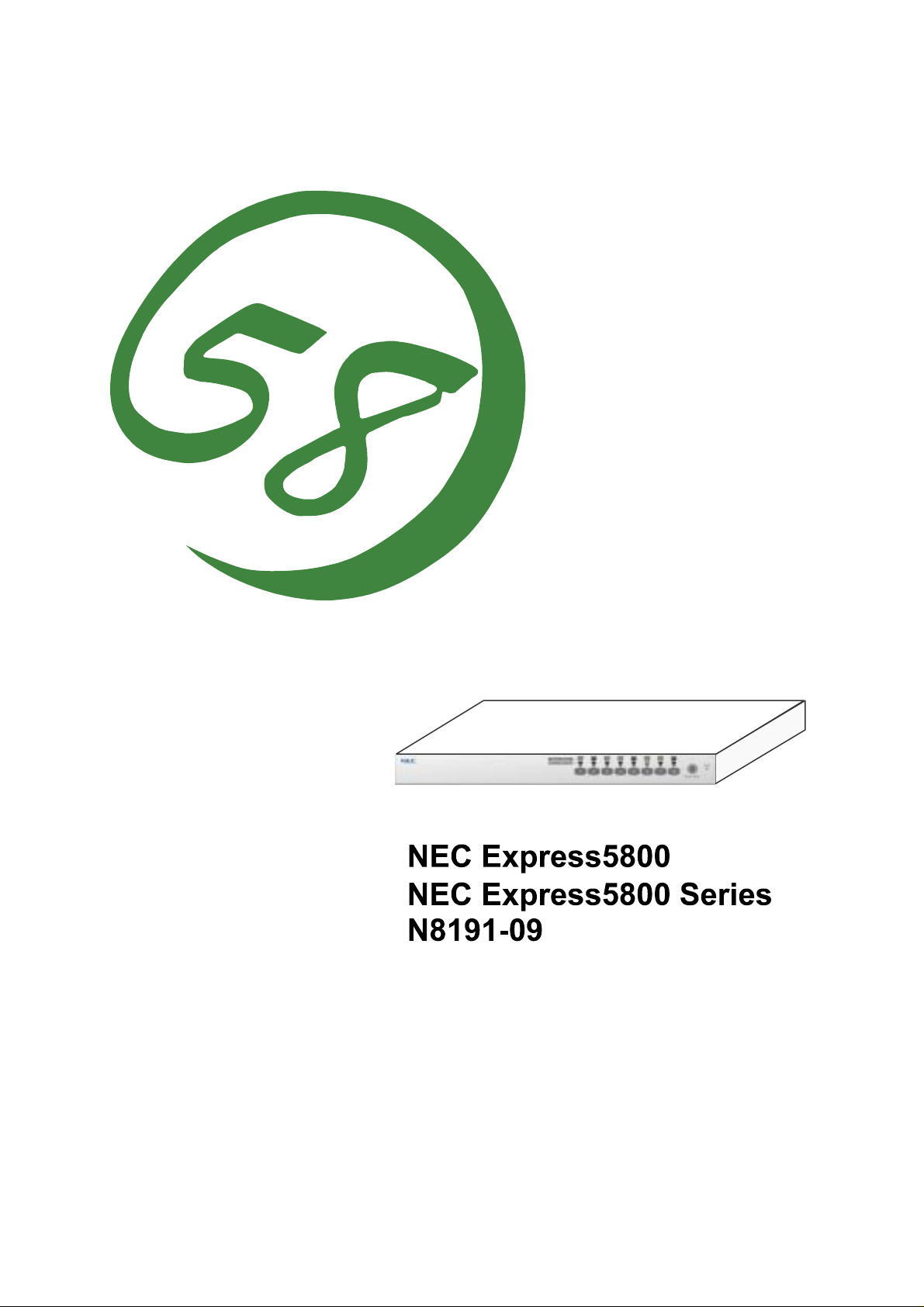
本書について
本書は、N8191-09 サーバスイッチユニットを正しく設置し、使用できるようにするための手
引きです。N8191-09 サーバスイッチユニットを日常使用する上で、わからないことや具合の
悪いことが起きたときは、取り扱い上の安全性を含めてご利用ください。
また本書は常に N8191-09 サーバスイッチユニットのそばに置いていつでも見られるように
してください。
なお、本書は和英併記となっております。日本語での説明は i ページから 39 ページを、英語
での説明は i ページから xxii ページおよび、40 ページから 74 ページを参照してください。
ABOUT THIS USER' S GUIDE
This User's Guide is intended to help the user install and use the N8191-09 server switch unit properly.
When encountering any questions and troubles in daily use of the N8191-09 server switch unit, use
this guide and also refer to safety precautions in it.
Keep this User's Guide near the N8191-09 server switch unit so that you can read it at any time you
need.
This User's Guide is written in both Japanese and English. For Japanese, refer to pages i to 39. For
English, refer to pages i to xxii and 40 to 74.
Page 4
日本語版
Japanese Edition
See page 40 for English version.
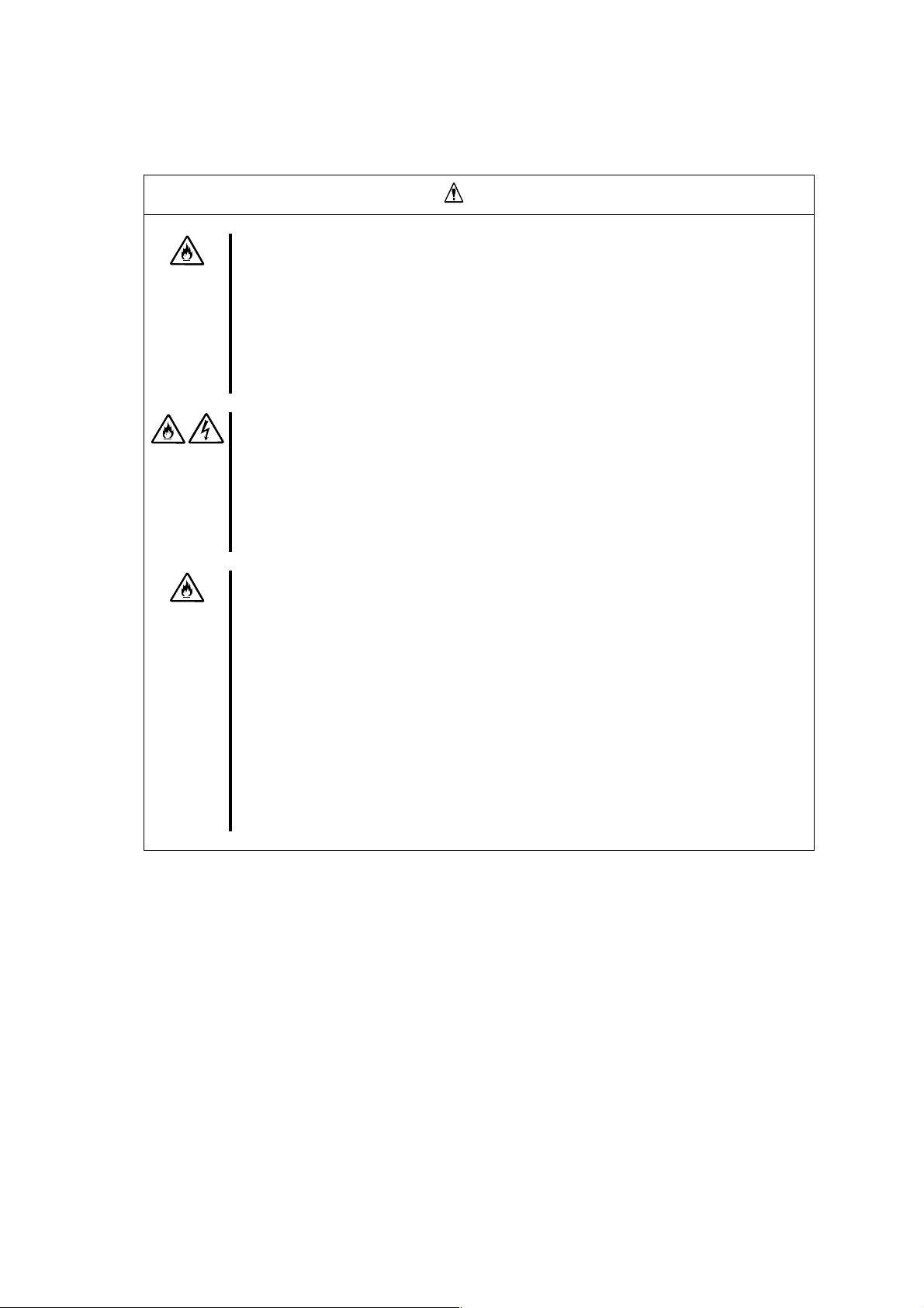
使用上のご注意 〜必ずお読みください〜
安全に関わる表示について
本書および警告ラベルで使用する記号
安全上のご注意
本文中の記号について
警告ラベルについて
取り扱い上のご注意 〜装置を正しく動作させるために〜
はじめに
付属品の確認
第三者への譲渡について
装置の廃棄について
本書を紛失してしまったら
1
セットアップ
サーバスイッチユニットの特徴
各部の名称とはたらき
設置
ケーブル接続
UPS
USB
RedHat Linux 7.2
2
基本的な操作
サーバの切り替え方
サーバ名称の表示/非表示
3
運用・保守
日常の保守
障害時の対処
移動と保管
ユーザーサポート
4
仕様
...................................................................................................................................................................xx
装置前面(コンソールパネル側)
装置背面(リアパネル側)
.............................................................................................................................................................................5
ラックの設置
〜サーバを8台まで接続する場合〜
〜9台以上のサーバを接続する場合〜
N8191-05
との接続について
キーボードとの接続について
セレクトスイッチによる選択(ノーマルモード)
キーボードによる選択(ホットキーモード)
....................................................................................................................................29
クリーニング
トラブルシューティング
保証について
修理に出される前に
保守サービス会社に連絡するときは
補修用部品について
保守サービスについて
情報サービスについて
...............................................................................................................................................39
...................................................................................................................................................iv
...........................................................................................................................................................xxi
.............................................................................................................................................xxiii
...............................................................................................................................1
........................................................................................................................................................5
............................................................................................................................................................10
との接続について
でのマウスの設定
.............................................................................................................................20
................................................................................................................................................20
...............................................................................................................................................................29
......................................................................................................................................................29
............................................................................................................................................................30
...............................................................................................................................................................35
....................................................................................................................................................36
......................................................................................................................................................36
..................................................................................................................................i
............................................................................................................iii
.....................................................................................................................................xvi
........................................................................................................................................xvii
.....................................................................................................................................xxiii
.................................................................................................................................xxiii
..............................................................................................................................1
..............................................................................................................................................2
.....................................................................................................................2
.................................................................................................................................3
...............................................................................................................11
............................................................................................................13
.............................................................................................................................15
...........................................................................................................................................16
......................................................................................................................16
......................................................................................................................19
....................................................................................................................................28
...................................................................................................................................30
..........................................................................................................................................36
...............................................................................................................37
..........................................................................................................................................37
......................................................................................................................................37
......................................................................................................................................38
.............................................................................................i
....................................................................xviii
.......................................................................................20
...............................................................................................21
Page 5

英語版
English Edition
See page 1 for Japanese version.
SAFETY PRECAUTIONS ..............................................................................................................................ii
Safety Indications...................................................................................................................................................ii
Symbols Used in This User's Guide and Warning Labels......................................................................................iii
Notes on Safety......................................................................................................................................................iv
Warning Labels...................................................................................................................................................xvii
Note on Handling ∼ For Proper Operation∼.........................................................................................................xix
Preface .......................................................................................................................................................................xx
Check of Accessories...............................................................................................................................................xxii
Transfer to Third Party ............................................................................................................................................xxiii
Disposal ..................................................................................................................................................................xxiii
1. Setting Up the Server Switch Unit...........................................................................................40
FEATURES OF SERVER SWITCH UNIT...............................................................................................................40
Names and Functions of Components........................................................................................................................41
Front View (Console Panel Side)..........................................................................................................................41
Rear View (Rear Panel Side)................................................................................................................................42
Installation .................................................................................................................................................................44
Installation of Rack...............................................................................................................................................44
Cable Connection.......................................................................................................................................................49
Connecting with Eight or Less Servers.................................................................................................................50
Connecting with Nine or More Servers................................................................................................................52
Connecting with N8191-05...................................................................................................................................54
Connecting the Server Switch Unit with UPS............................................................................................................55
Settings for the Mouse on RedHat Linux 7.2.............................................................................................................55
2. Using the Server Switch Unit ................................................................................................. 56
Switch of Server Switch Unit.....................................................................................................................................56
Selection of Server by Server Selection Switch (Normal Mode)..........................................................................56
Selection of Server on Keyboard (Hot Key Mode)...............................................................................................57
Display/Hide the Server Name...................................................................................................................................64
3. Maintaining the Server Switch Unit ....................................................................................... 65
Daily Maintenance.....................................................................................................................................................65
Cleaning................................................................................................................................................................65
Troubleshooting.........................................................................................................................................................66
Relocation and Storage of Server Switch Unit...........................................................................................................71
User Support ..............................................................................................................................................................72
Maintenance Service.............................................................................................................................................72
Before Having the Unit Repaired..........................................................................................................................72
When Having the Unit Repaired...........................................................................................................................73
Spare Parts............................................................................................................................................................73
4. Specifications............................................................................................................................74
Page 6
シリーズ
サーバスイッチユニット
Server Switch Unit
ユーザーズガイド
User's Guide
Page 7
本装置の使用につきましては、本書および、NEC Express サーバに添付のユーザーズガイドを参照の
上ご使用願います。また、ご使用の前に「使用上のご注意」を必ずお読みください。本書をお読みに
なった後は、必要なときにすぐに参照できるようお手元においておくようにしてください。
使用上のご注意 〜必ずお読みください〜
サーバスイッチユニットを安全に正しくご使用になるために必要な 情報が記 載 されてい ま す。
安全に関わる表示について
本装置を安全にお使いいただくために、このユーザーズガイドの指示に従って操作してくだ
さい。
本書には、ご使用時にどこが危険であるか、指示を守らないとどのような危険にあうか、ど
うすれば危険を避けられるかなどについて説明されています。
また、使用時に危険が想定される個所、或いはその付近には警告ラベルが貼り付けられてい
ます。
本書および警告ラベルでは、危険の程度を表す用語として、「警告」と「注意」を使用してい
ます。それぞれの用語は、次のような意味を持つものとして定義されています。
警告
注意
安全上のご注意を無視する取り扱いを行うと、装置の故障、人体事故、火
災・周囲の機器の損傷を引き起こす原因となることがあります。
この表示を無視した取り扱いをすると、使用者が傷害を負うおそれが想定
される事項、および物的損害のみの発生が想定される事項です。
危険に対する注意・表示には次の 3 種類の記号を使用しています。それぞれの記号は次のよ
うな意味を持つものとして定義されています。
この記号は指示を守らないと、危険が発生するおそれがあることを
注意の喚起
行為の禁止
行為の強制
表しています。記号の中の絵表示は危険の内容を図案化したもので
す。
この記号は行為の禁止を表しています。記号の中や近くの絵表示は、
禁止された行為の内容を図案化したものです。
この記号は行為の強制を表しています。記号の中の絵表示は必要な
行為の内容を図案化したものです。危険を避けるためには、この行
為が必要です。
- i -
Page 8
Read this "Safety Precautions" and separately provided User's Guide thoroughly before getting started
to use this device safely. After you have read this brochure, store it in the place that is easy to access.
SAFETY PRECAUTIONS
This section describes the information necessary to use the server switch unit safely.
Safety Indications
Follow the instructions described in this User's Guide for your safety to use the server switch unit.
The server switch unit contains components with possible danger, hazards that may cause by ignoring
warnings, and preventive actions against such hazards.
Server switch unit components with possible danger are indicated with a warning label placed on or
around them as well as described in this User's Guide.
In the User's Guide or warning labels, "WARNING" or "CAUTION" is used to indicate a degree of
danger. These terms are defined as follows:
This symbol indicates that using the product improperly in defiance of this
WARNING
CAUTION
symbol is likely to result in death, serious injury, fire, or damage to the
device and peripherals.
This symbol indicates that using the product improperly in defiance of this
symbol may result in injury or only damage to property.
Precautions and notices against hazards are presented with one of the following three symbols.
The individual symbols are defined as follows:
Attention This symbol indicates the presence of a hazard if the instruction is
Prohibited
Action
Mandatory
Action
ignored.
An image in the symbol illustrates the hazard type.
This symbol indicates prohibited actions. An image in the symbol
illustrates a particular prohibited action.
This symbol indicates mandatory actions. An image in the symbol
illustrates a mandatory action to avoid a particular hazard.
- ii -
Page 9
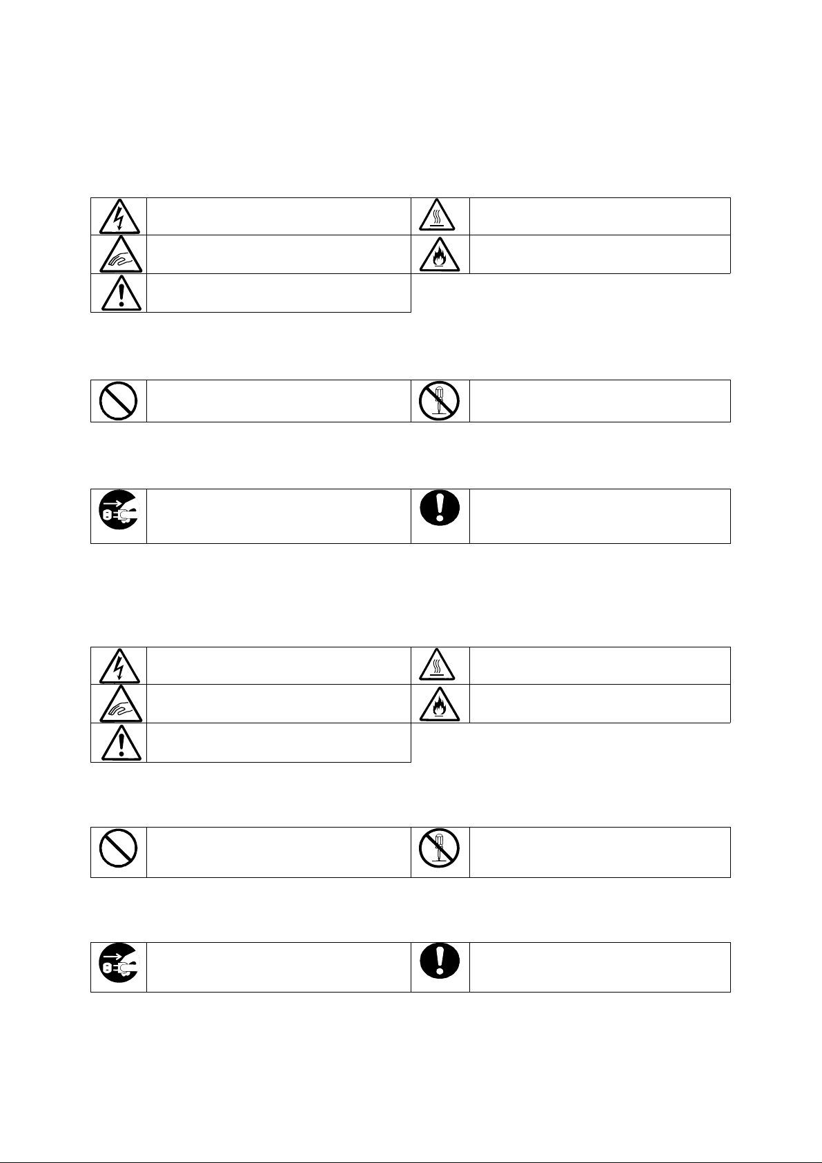
本書および警告ラベルで使用する記号
注意の喚起
感電のおそれがあることを示します。
指などが挟まれるおそれがあることを示
します。
特定しない一般的な注意・警告を示しま
す。
高温による損害を負うおそれがあるこ
とを示します。
発煙または発火のおそれがあることを
示します。
行為の禁止
特定しない一般的な禁止を示します。
本装置を分解・修理・改造しないでくだ
さい。感電や火災のおそれがあります。
行為の強制
本装置の電源プラグをコンセントから抜
いてください。火災や感電のおそれがあ
ります。
特定しない一般的な使用者の行為を指
示します。説明に従った操作をして下さ
い。
Symbols Used in This User's Guide and Warning Labels
Attentions
Indicates the risk of electric shock.
Indicates the risk that your fingers may
be caught.
Indicates a general notice or warning
that cannot be specifically identified.
Prohibited Actions
Indicates the notification of general
prohibition.
Mandatory Action
Unplug the AC cord of the server switch
unit. Otherwise, an electric shock or fire
may be caused.
Indicates the risk of an injury due to high
temperature.
Indicates the risk of smoke emission or
fire outbreak.
Do not disassemble, repair, or modify
the server switch unit. Otherwise, an
electric shock or fire may be caused.
Indicates a mandatory action that
cannot be specifically identified. Make
sure to follow the instruction.
- iii -
Page 10

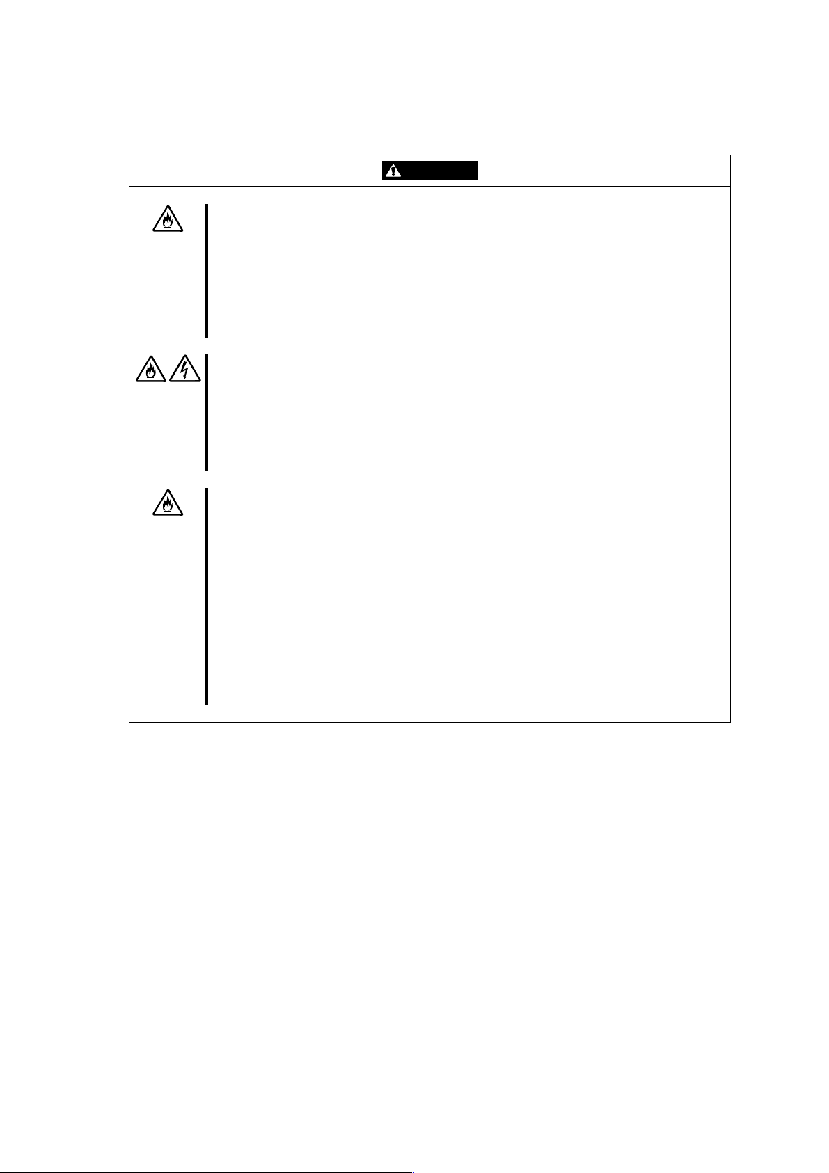
安全上のご注意
サーバスイッチユニットを安全にお使いいただくために、ここで説明する注意事項をよく読
んでご理解し、安全にご活用ください。記号の説明については巻頭の『安全に関わる表示に
ついて』の説明を参照してください。
Notes on Safety
To enable you to use the server switch unit safely, read the notes described below carefully to
understand them. See "Safety Indications" described earlier for the descriptions of symbols.
- iv -
Page 11
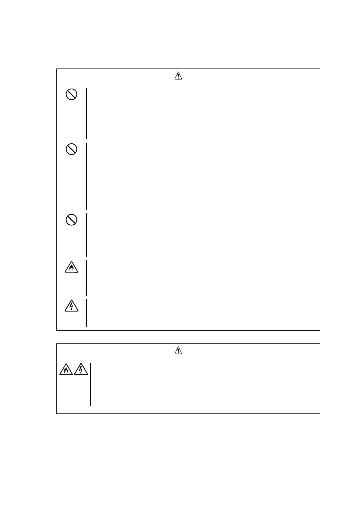
全般的な注意事項
人命に関わる業務や高度な信頼性を必要とする業務には使用しない
本装置は、医療機器・原子力設備や機器、航空宇宙機器・輸送設備や機器など、人命
に関わる設備や機器および高度な信頼性を必要とする設備や機器などへの組み込み
やこれらの機器の制御を目的とした使用は意図されておりません。これらの設備や機
器、制御システムなどに本装置を使用した結果、人身事故、財産被害などが生じても
当社はいかなる責任も負いかねます。
指定以外の場所で使用しない
本装置はEIA 規格に適合したExpress サーバ用の19 インチラックに取り付けて使用
することもできます。本装置を取り付けるラックを設置環境に適していない場所には
設置しないでください。
本装置やラックに取り付けているその他のシステムに悪影響をおよぼすばかりでな
く、火災やラックの転倒によるけがなどをするおそれがあります。設置場所に関する
詳細な説明や耐震工事についてはラックに添付のマニュアルを参照するか、保守サー
ビス会社にお問い合わせください。
規格以外のラックで使用しない
本装置はEIA 規格に適合したExpress サーバ用のラックに取り付けて使用すること
ができますが、EIA 規格に適合していないラックへは取り付けないでください。規格
外のラックへ取り付けると落下し、けがや周囲の破損の原因になることがあります。
本装置で使用できるラックについては保守サービス会社にお問い合わせください。
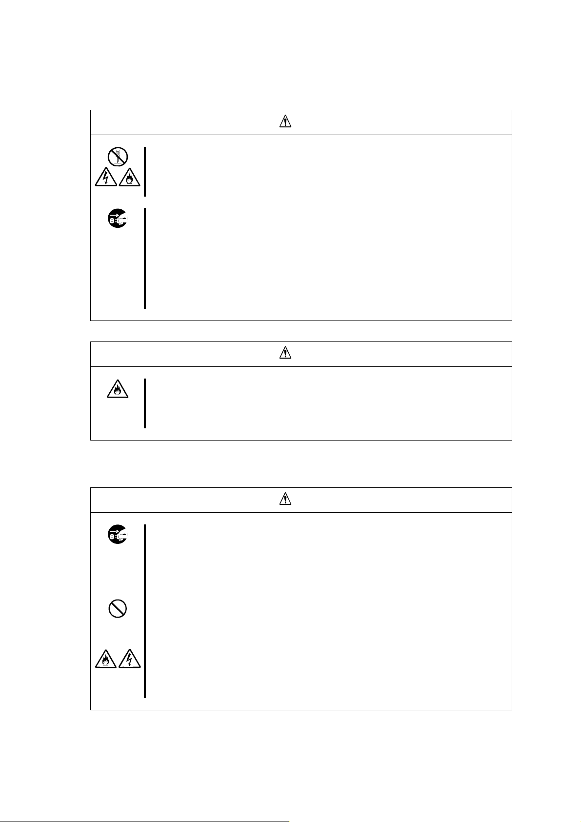
煙や異臭、異音がしたまま使用しない
万一、煙、異臭、異音などが生じた場合は、ACケーブルをコンセントから抜いてく
ださい。その後、お買い求めの販売店または保守サービス会社にご連絡ください。そ
のまま使用すると、火災の原因となります。
針金や金属片を差し込まない
装置のすきまから金属片や針金などの異物を差し込まないでください。感電の危険が
あります。
警告
注意
装置内に水や異物を入れない
装置内に水などの液体、ピンやクリップなどの異物を入れないでください。火災や
感電、故障の原因となります。もし入ってしまったときは、すぐ電源をOFFにして、
ACケーブルをコンセントから抜いてください。分解しないで販売店または保守サー
ビス会社にご連絡ください。
- v -
Page 12
General
The server switch unit is not intended to be used with or control facilities or devices
WARNING
Do not use the server switch unit for services involving human lives or requiring
igh reliability. h
concerning human lives, including medical devices, nuclear facilities and devices,
aeronautics and space devices, transportation facilities and devices; and facilities
and devices requiring high reliability. NEC assumes no liability for any accident
resulting in personal injury, death, or property damage if the server switch unit has
een used in the above conditions. b
Do not use the server switch unit in any unapproved place.
You can install the server switch unit on a standard EIA 19-inch rack assembly
using a general-purpose tray.
Do not install the rack containing the server switch unit in a place inapprop riate to
the rack installation environment.
Failure to follow these instructions may cause some bad influences to be imposed
on the server switch unit and other systems installed on the rack and also a fire o r
personal injury due to falling of the rack may occur. For the detailed explanation on
the place where the rack should be installed and the earthquake-resistant
construction for the rack, refer to the manual attached to the rack or contact you
ervice representative. s
Do not install the server switch unit on a rack not conformed to the relevant
tandard. s
You can install the server switch unit on a rack conforming to the EIA standard
using a general-purpose tray.
Do not use the server switch unit with installed on any other rack than standard EIA
19-inch rack. Failure to follow these instructions may cause personal injury or
damages of surrounding devices due to falling of the unit. Contact your service
epresentative for the racks available for the server switch unit. r
Do not use the server switch unit if any smoke, odor, or noise is present.
If smoke, odor, or noise is present, immediately disconnect the AC cord from the
outlet. Then contact your service representative. Using the server switch unit in
uch conditions may cause a fire. s
Keep needles or metal objects away from the server switch unit.
Do not insert needles or metal objects into the server switch unit. Doing so may
ause an electric shock. c
CAUTION
Keep water or foreign matter away from the server switch unit.
Do not let any form of liquid (water etc.) or foreign matter (e.g., pins or paperclips)
enter the server switch unit. Failure to follow this warning may cause an electric
shock, a fire, or a failure of the unit. When such things accidentally enter the server
switch unit, immediately turn off the power and disconnect the AC cord from the
outlet. Do not disassemble the server switch unit. Contact your service
epresentative. r
- vi -
Page 13
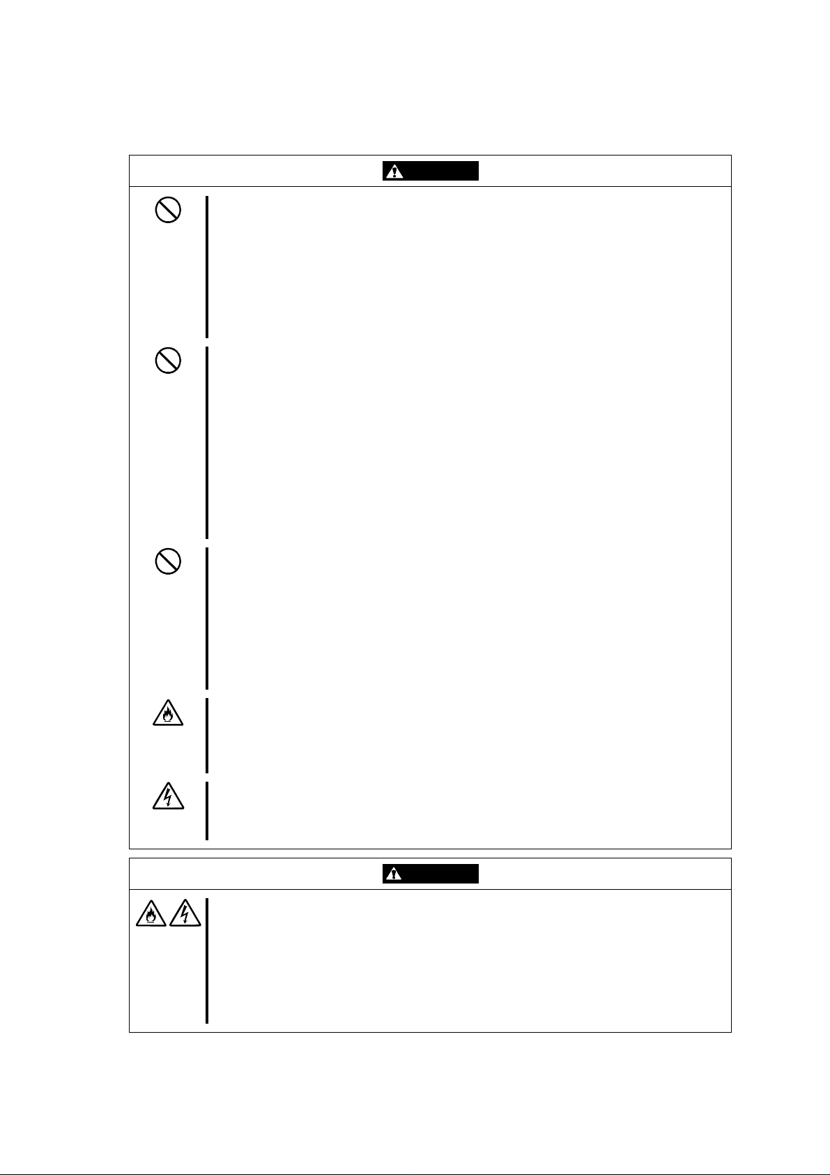
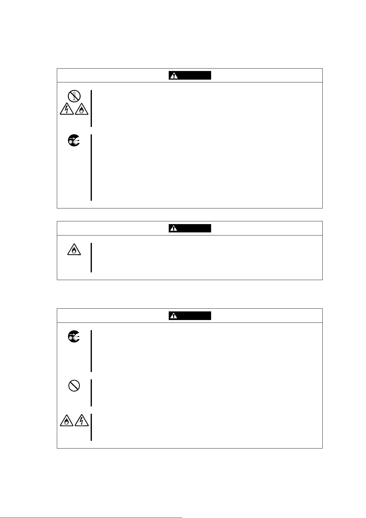
電源に関する注意事項
指定以外のコンセントに差し込まない
電源は指定された電圧・電源のコンセントをお使いください。指定以外の電源を使
うと火災や漏電の原因となります。
また、延長コードが必要となるような場合には設置しないでください。本装置の電
源仕様に合ってないコードに接続すると、コードが加熱して火災の原因となります。
たこ足配線にしない
コンセントに定格以上の電流がながれることによって、加熱して火災の原因となる
おそれがあります。
中途半端に差し込まない
ACケーブルのプラグ部分は根元までしっかりと差し込んでください。中途半端に差
し込むと接触不良のため発熱し、火災の原因となることがあります。また差し込み
部にほこりがたまり、水滴などが付くと発熱し、火災の原因となるおそれがありま
す。
指定以外のACケーブルを使わない
本装置に添付されている以外のACケーブルを使用しないでください。本体に定格以
上の電圧がかかると、故障や火災の原因となるおそれがあります。
また、ACケーブルの破損による感電や火災を防止するために次のような行為を行な
わないでください。
n コード部分を引っ張らない。
n コードをはさまない。
n コード部分を折り曲げない。
n ACケーブルに薬品類をかけない。
n コード部分をねじらない。
n ACケーブルにものを載せない。
n コード部分を束ねない。
n ACケーブルを改造・加工・修復しない。
n コードが損傷したら使わない。(コードが損傷したらすぐに新しいACケーブル
にお取り替えてください。お取り替えに関しては、お買い求めの販売店または保
守サービス会社にご連絡ください。)
注意
- vii -
Page 14
Power Supply and Power Cord Use
Plug in to a proper power source.
Use a proper wall of specified voltage and current. Use of an improper power
source may cause a fire or a power leak.
Do not install the server switch unit where you need an extension cord. Use of a
cord that does not meet the power specifications of the server switch unit may heat
up the cord and cause a fire.
Do not connect the power cord to an outlet that has an illegal number of
connections.
The electric current exceeding the rated flow overheats the outlet, which may cause
a fire.
Do not connect the power cord to an outlet that has an illegal number of
onnections. c
The electric current exceeding the rated flow overheats the outlet, which may cause
a fire.
Plug the AC cord into the outlet as far as it goes.
Heat generation resulting from a halfway inserted AC cord (imperfect contact) may
cause a fire. Heat will also be generated if condensation is formed on dusty blades
of the halfway inserted plug, increasing the possibility of fire.
Use the authorized AC cord only.
Use only the proper AC cord that comes with the server switch unit. Use of an
unauthorized AC cord may cause a fire when the electric current exceeds the ra ted
flow. AC cord for Japan (100 VAC) is provided with the server switch unit. Do not
use the provided AC cord in any other country than Japan.
Also, observe the following to prevent an electric shock or fire caused by a
damaged AC cord.
n Do not stretch the cord harness.
n Do not pinch the power cord.
n Do not bend the power cord.
n Keep chemicals away from the AC cord.
n Do not twist the power cord.
n Do not place any object on the AC cord.
n Do not bundle power cords.
n Do not alter, modify, or repair the AC cord.
n Do not use any damaged power cord. (Replace a damaged AC cord with a new
one of the same specifications. Ask your service representative for replacement.)
CAUTION
- viii -
Page 15
ラックの設置・取り扱いに関する注意事項
一人で搬送・設置をしない
ラックの搬送・設置は2人以上で行ってください。ラックが倒れてけがや周囲の破損
の原因となります。特に高さのあるラック(44U ラックなど)はスタビライザなどに
よって固定されていないときは不安定な状態にあります。必ず2 人以上でラックを
支えながら搬送・設置をしてください。
荷重が集中してしまうような設置はしない
ラック、および取り付けた装置の重量が一点に集中しないようスタビライザを取り
付けるか、耐震固定を施してください。複数台のラックを使用している場合は、連
結して荷重を分散してください。ラックが倒れてけがをするおそれがあります。
一人で部品の取り付けをしない
ラック用のドアやトレーなどの部品は2人以上で取り付けてください。部品を落とし
て破損させるばかりでなく、けがをするおそれがあります。
複数台のデバイスをラックから引き出した状態にしない
複数台のデバイスをラックから引き出すとラックが倒れるおそれがあります。装置
は一度に1台ずつ引き出してください。
定格電源を越える配線をしない
やけどや火災、装置の破損を防止するためにラックに電源を供給する電源分岐回路
の定格負荷を越えないようにしてください。電気設備の配線とインストール要件に
関しては、電源工事を行った業者、または管轄の電力会社にお問い合わせください。
注意
- ix -
Page 16
Rack
CAUTION
Do not carry or install the rack only by a single person.
At least two persons are required to carry or install the rack. Failure to follow this
instruction may cause the rack to fall to result in personal injury and/or breakage of
surrounding devices. In particular, a high rack (such as 44U rack) is unstable if it is
not fixed by stabilizers. At least two persons must always carry or install the rack
while they support it.
Do not install the rack so that the load may be concentrated on a specific point.
Install stabilizers on the rack or earthquake-resistant construction to the rack so that
the total load of the rack and devices mounted on the rack is not concentrated on a
single point. Join the racks in multiple-rack installations to distribute the load.
Failure to follow this instruction may cause the rack to fall to result in personal
injury.
Do not install components on the rack only by yourself.
At least two persons are required to install parts including the doors and trays for
the rack. Failure to follow this instruction may cause some parts to fall to be broken
and/or to result in personal injury.
Do not leave more than one device being pulled out from the rack.
Pulling out more than one device from the rack may cause the rack to be fallen.
Only pull out a single device from the rack at a time.
Do not provide the wiring for the rack to exceed the rating of the power supply.
To prevent burns, fires, and device damages, the power supplied to the power
supply in the rack shall not exceed the rating load of the power branch circuit.
Contact the power constructor or local power company for the requirements on the
wiring and installation of electric facilities.
- x -
Page 17
設置・移動・保管・接続に関する注意事項
指定以外の場所に設置しない
本装置を次に示すような場所や本書で指定している場所以外に置かないでくださ
い。火災の原因となるおそれがあります。
n ほこりの多い場所
n 直射日光が当たる場所
n 給湯器のそばなどの湿気の多い場所
n 不安定な場所
サーバの電源がONのままや、ACケーブルを接続したままインタフェースケーブル
の取り付けや取り外しをしない
インタフェースケーブルの取り付け/取り外しはサーバの電源をOFFし、ACケーブ
ルをコンセントから抜いてから行なってください。たとえ、サーバの電源がOFFさ
れていてもACケーブルを接続したままケーブルに触ると感電したり、ショートによ
る火災を起こしたりするおそれがあります。
指定以外のインタフェースケーブルを使用しない
インタフェースケーブルは、NEC が指定するものを使用し、接続する装置やコネク
タを確認した上で接続してください。指定以外のケーブルを使用したり、接続先を
誤ったりすると、ショートにより火災を起こすことがあります。
また、インタフェースケーブルの取扱いや接続について次の注意をお守りください。
n 破損したケーブルコネクタを使用しない。
インタフェースケーブルを接続する前に、ケーブルコネクタが破損していたり、
コネクタピンが曲がっていたり汚れたりしていないことを確認してください。
n ケーブルを履まない。
n ケーブルの接続がゆるんだまま使用しない。
n ケーブルの上にものを載せない。
n ネジ止めなどのロックを外したまま使用しない。
注意
- xi -
Page 18
Installation, Relocation, Storage, and Connection
CAUTION
Do not install the server switch unit in any other place than specified.
Do not install the server switch unit in the following places or any other places than
specified in this User's Guide. Failure to follow this instruction may cause a fire.
n a dusty place
n a humid place such as near a boiler
n a place exposed to direct sunlight
n an unstable place
Do not connect any interface cable to the server switch unit with the server being
powered or the AC cord being connected.
Make sure to power off the server and unplug the AC cord from an outlet before
connecting/disconnecting the interface cable. If the server is off-powered but its AC
cord is plugged to a power source, touching the cable may cause an electric shock
or a fire resulted from a short circuit.
Do not use any unauthorized interface cable.
Use only interface cables specified by NEC and locate a proper device and
connector before connecting a cable. Using an unauthorized cable or connecting a
cable to an improper destination may cause a short circuit, resulting in a fire.
Also, observe the following notes on using and connecting an interface cable.
n Do not use any damaged cable connector. Before connecting an interface cable,
confirm that any cable connector is not damaged and any connector pin is not
bent or dirt.
n Do not step on the cable.
n Do not use the server switch unit with loose cable connections.
n Do not place any object on the cable.
n Do not disable the locking mechanism of the connectors.
- xii -
Page 19
お手入れ関する注意事項
自分で分解・修理・改造はしない
絶対に分解したり、修理・改造をおこなったりしないでください。装置が正常に動
作しなくなるばかりでなく、感電や火災の危険があります。
プラグを抜かずに取り扱わない
お手入れの際は、サーバの電源をOFFにして、ACケーブルをコンセントから抜いて
行なってください。サーバの電源がONになっていたり、ACケーブルを接続したま
まコネクタに触れると感電したりショートによる火災を起こすおそれがあります。
また、ACケーブルはときどき抜いて、乾いた布でほこりやゴミをよくふき取ってく
ださい。ほこりがたまったままで水滴などが付くと、発熱し、火災の原因となるお
それがあります。
警告
中途半端に取り付けない
ACケーブルやインタフェースケーブルは確実に取り付けてください。中途半端に取
り付けると接触不良を起こし、発煙や発火の原因となるおそれがあります。
運用中の注意事項
雷がなったら触らない
雷が発生しそうなときはACケーブルをコンセントから抜いてください。またAC
ケーブルを抜く前に、雷が鳴りだしたら、ケーブル類も含めて装置には触れないで
ください。火災や感電の原因となります。
近くで携帯電話やPHS、ポケットベルを使わない
本装置のそばでは携帯電話やPHS、ポケットベルの電源をOFF にしておいてくだ
さい。電波による誤動作の原因となります。
ペットを近づけない
本装置にペットなどの生き物を近づけないでください。排泄物や体毛が装置内部に
入って火災や感電の原因になります。
注意
注意
- xiii -
Page 20
Cleaning
WARNING
Do not disassemble, repair, or alter the server switch unit.
Do not attempt to disassemble, repair, or alter the server switch unit. Failure to
follow this instruction may cause an electric shock or fire as well as malfunctions of
the unit.
Disconnect the AC cord before cleaning the server swit ch unit.
Make sure to power off the server and disconnect the AC cord from a power outlet
before cleaning. Touching any connectors with the server's power being on or with
the AC cord being connected to a power source may cause an electric shock or a
fire due to short circuit.
Also, disconnect the AC cord from the outlet occasionally and clean the plug with a
dry cloth. Heat will be generated if condensation is formed on a dusty plug, which
may cause a fire.
CAUTION
Make sure to complete cable and AC cord installations.
Always install the AC cord and an interface cable firmly. An incomplete installation
may cause a contact failure, resulting in smoking or fire.
During Operation
Do not touch the server switch unit when it thunders.
Disconnect the AC cord from the outlet when a thunderstorm is approaching. If it
starts thundering before you disconnect the AC cord, do not touch any part of the
server switch unit including cables. Failure to follow this warning may cause a fire or
an electric shock.
Do not use a cellular phone or pager around the server switch unit.
Turn off the cellular phone or pager around the server switch unit. Radio
interference may cause malfunctions of the server switch unit.
Keep any animal (pet) away from the server switch unit.
Pet's discharges or fur may enter the server switch unit and cause a fire or electric
shock.
CAUTION
- xiv -
Page 21

- xv -
Page 22
本文中の記号について
本書の日本語で表記されている部分には、先に示した安全にかかわる注意事項記号の他に 4
種類の記号を使用しています。これらの記号と意味をご理解になり、装置を正しくお取り扱
いください。
装置の取り扱いや、操作で守らなければならない事柄や特に注意すべき
点を示します。
装置の取り扱いや、ソフトウエアの操作で守らなければならない事柄や
特に注意をすべき点を示します。
知っておくと役に立つ情報や、便利なことなどを示します。
発生したトラブルの事例を示します。
Text Conventions
The following conventions are used throughout this manual written in English. For safety symbols,
see "SAFETY INDICATIONS" described earlier.
Items to be observed or points to be noted when operating the server
Notice
4
Check
Tips
switch unit.
Items to be checked when operating the server switch unit or using
software.
Information useful or convenient for you
Example of troubles occurred.
- xvi -
Page 23
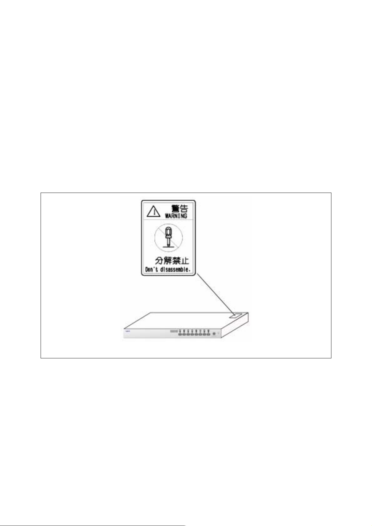
警告ラベルについて
本装置には、危険性を秘める部品やその周辺には警告ラベルが貼り付けられています。これ
は本装置を操作する際に、考えられる危険性を常にお客様に意識して頂くためのものです(ラ
ベルをはがしたり汚したりしないでください)。もしこのラベルが貼り付けられていない、は
がれかかっている、汚れているなどして判読不能な状態でしたら、販売店にご連絡ください。
Warning Labels
The warning label is attached to components with possible danger or their vicinity in the server switch
unit to inform the user that a hazardous situation may arise when operating the unit (do not take off
any label or soil it). If you find any label unattached, almost peeled off, or soiled, making the warning
illegible, contact your service representative.
- xvii -
Page 24
取り扱い上のご注意 〜装置を正しく動作させるために〜
本装置を正しく動作させるために、次に示す注意事項をお守りください。これらの注意を無
視した取り扱いをすると、誤動作や故障の原因となります。
n 本装置へのケーブルの接続/取り外しは、サーバ側の電源が OFF になっていることを
確認し、AC ケーブルをコンセントから外した後に行ってください。
n 本装置を移動する前に Server Online ランプが消灯していることを確認し、AC ケーブ
ルをコンセントから抜いてください。
n 定期的に本装置を清掃してください(クリーニングについては 3 章で説明しています)。
定期的な清掃はさまざまな故障を未然に防ぐ効果があります。
n 落雷等が原因で瞬間的に電圧が低下することがあります。この対策として無停電電源装
置等を使用することをお勧めします。
n 本装置に接続するキーボード、マウスは Express サーバシステムとして購入されたもの
を使用してください。指定以外のものを使用すると正常に動作しないばかりか、装置本
体が故障することがあります。
n 本装置のスイッチを同時に 2 つ以上押さないでください。誤動作する恐れがあります。
n 本装置に添付されている以外の AC ケーブルを使用しないでください。本装置に定格以
上の電圧がかかると、故障や火災の原因となるおそれがあります。またこれらの製品が
原因となって起きた故障や破損については保証期間中でも有償修理となります。
n オプションのインターフェースケーブルは NEC の純正品をお使いください。他社製の
ケーブルを使用し、これらの製品が原因となって起きた故障や破損については保証期間
中でも有償修理となります。
保守サービスについて
Express サーバの保守に関して専門的な知識を持つ保守員による定期的な診断・保守
サービスを用意しています。
Express サーバをいつまでもよい状態でお使いになるためにも、保守サービス会社と
定期保守サービスを契約されることをお勧めします。
- xviii -
Page 25

Note on Handling ∼ For Proper Operation∼
Observe the following notes for successful operation of the server switch unit. Use of the server
switch unit ignoring the notes will cause malfunctions or failures of the unit.
n Make sure to power off the server switch unit and disconnect the AC cord from the power outlet
before connecting or disconnecting cables.
n Check to see that the Server Online lamp goes off and unplug the power cord from the outlet
before relocating the server switch unit.
n Clean the server switch unit on a regular basis (see Chapter 3). Regular cleaning proactively
prevents various failures of the unit.
n Lightning may cause a momentary voltage drop. To prevent this problem, it is recommended
to use an uninterruptible power supply.
n Use the keyboard and mouse which you purchased as components in the NEC Express5800
server system to connect them with the server switch unit. Using any other unauthorized
keyboard and mouse cause failures of the unit as well as a malfunction of the unit.
n Do not press two or more switches simultaneously. Doing so may cause a malfunction of the
unit.
n Use only the AC cord that comes with the server switch unit. Use of an unauthorized AC cord
may cause a failure of the unit or a fire when the voltage exceeding the rated one is applied to
the unit.
n Use NEC's genuine interface cables for options. Repair of the unit due to a failure or damage
resulted from use of a third-party product will be charged even in the warranty period.
- xix -
Page 26

はじめに
このたびは、N8191-09 サーバスイッチユニットをお買い求めいただき、まことにありがとう
ございます。
本装置はExpress サーバ用に開発されたサーバ切り替えスイッチです。1 組のディスプレイ、
キーボード、マウスで8 台のサーバを操作することができます。また、本装置を 9 台カスケー
ド接続することで最大 64 台のサーバを操作することができます。サーバの選択は Server
Selection スイッチまたはキーボードから簡単に行えます。
本書は本装置を正しく使用できるようにするための手引きです。本書に記載されている内容
を良く理解された上で本装置を正しく、確実に操作してください。
PREFACE
Welcome to our N8191-09 Server Switch Unit.
The Server Switch Unit N8191-09 is a switching device developed for the NEC Express5800 server.
With this unit, up to eight servers can be operated with one each of display unit, keyboard, and mouse
(in the cascade connection, up to 64 servers can be operated). You can easily select the desired server
using the Server Selection switch or the keyboard.
This manual is a guidance to use the unit properly. Read well the manual to operate the unit properly
and surely.
- xx -
Page 27
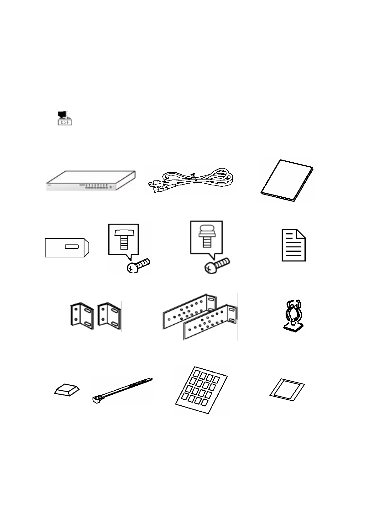
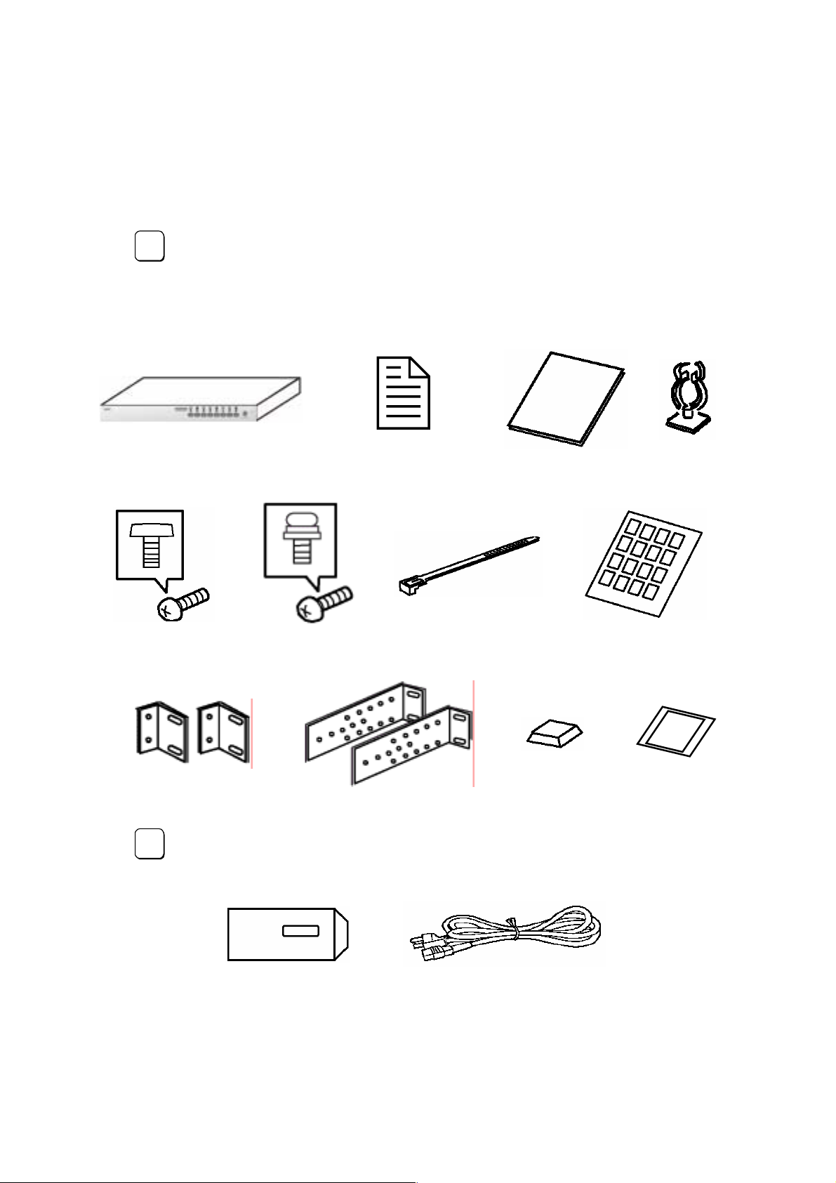
付属品の確認
本装置の梱包箱の中には、本体以外にいろいろな付属品が入っています。以下に示す付属品
がすべてがそろっていることを確認し、それぞれ点検してください。万一足りないものや損
傷しているものがある場合は、販売店に連絡してください。
付属品について
添付品はセットアップをするときに必要となりますので大切に保管してく
ださい。
□本体×1 □AC ケーブル×1 □ユーザーズガイド(本書)×1
□保証書×1 □ネジ大(M5×10) ×8 □ネジ小(M3×6) ×10 □使用上の注意×1
□ラックマウントブラケット(小) ×2 □ラックマウントブラケット(大)×2 □ケーブルクランプ×1
□ゴム足×4 □ケーブルタイ×10 □行き先表示ラベル
(1 シート 36 枚)
□DIP SW 設定ラベル ×1
- xxi -
Page 28
CHECK OF ACCESSORIES
The carton of the server switch unit contains several accessories as well as the unit. Make sure that
all items listed below are provided and then inspect them. If one or more items are missing or
defective, contact your service representative.
The accessories are required for the setup of the server switch unit or the
Tips
addition of an optional device. Store them carefully.
Server switch unit (N8191-09) Notice for using N8191-09
Server Switch Unit ×1
Screw A (M5) × 8 Screw B (M3) × 10 Tie wrap × 10
Rack mount brackets (small)
× 2
Rack mount brackets (large)
× 2
User's Guide Cable clamp
Device ID label
(36 pcs. per sheet)
Shock absorbers
× 4
DIP switch setup
label ×1
These accessories are available only for using in Japan.
Tips
Do not use them in any other country than Japan.
Warranty AC Cord for Japan (100 VAC)
- xxii -
Page 29

第三者への譲渡について
本装置または、本装置に添付されているものを第三者に譲渡(または売却)するときは、本
書を一緒にお渡しください。
TRANSFER TO THIRD PARTY
To transfer or sell the server switch unit or the accessories that come with the server switch unit to a
third party, make sure to provide this User's Guide together with the unit or the accessories to a third
party.
装置の廃棄について
本装置や AC ケーブル、またはオプションの専用ケーブルの廃棄については、各自治体の廃
棄ルールに従ってください。詳しくは、各自治体へお問い合わせください。
DISPOSAL
Dispose the server switch unit, provided AC cord, or optional interface cables according to all laws
and regulations of the local government.
本書を紛失してしまったら
もし本書を紛失された場合は、最寄りの販売店、またはお買い求めの販売店に品名、型名を
指定してお申し込みください。本書を再購入することができます。
- xxiii -
Page 30

セットアップ
この章では、本装置の特徴や本装置を使用する上で知っておいていただきたい各部の名称や
その設置方法、取り扱い方法について説明します
サーバスイッチユニットの特徴
n 複数台のサーバを本装置に接続することで、今まで各サーバ毎に接続していた複数台の
コンソール(ディスプレイ、キーボード、マウス)を 1 組のコンソールで操作すること
ができます。これにより設置スペースの大幅な節約が実現できます。
n 本装置 1 台で最大 8 台のサーバが選択できます。
n 本装置を最大 9 台使用してカスケード接続すると、最大 64 台のサーバが選択可能とな
ります。
n 19 インチ EIA 規格ラックに高さ 1U のスペースで収納できます。
n ラック取付け時には、コンソールパネル部とリアパネル部(本体)が分離しているため
ラック内でのサーバへの接続作業がよりスムーズに行えます。
n 本装置は全ポート(キーボード、マウス、各 Server ポート)毎に独立した制御用マイ
コン(MPU)が内蔵されています。従って、各サーバのキーボードとマウスの状態(キー
コードモード、Num、Caps、Scroll 状態とマウス出力モード)は各ポートの MPU がそ
れぞれ監視しますので、常に安定した切替が実現できます。
n 電源電圧監視回路を内蔵していますので、AC ケーブルが外れたり内部電源ヒューズが
故障したときに異常をお知らせします。(Server Online ランプが点滅します)。
n Express サーバ専用の PS/2 タイプのキーボードとマウスをサポートします。
n Express サーバ専用の英語/日本語キーボード(101〜109)をサポートします。
n ディスプレイは、VGA/SVGA/マルチシンクの解像度 1600x1200、リフレッシュレー
ト 75Hz までをサポートします。
n サーバの選択は Server Selection スイッチ、キーボード(ホットキーモード)で簡単に
できます。
n ホットキーモードでは OSD(On Screen Display)表示により、画面を見ながら切替が
できます。
n オートスキャンはスイッチとホットキーで行えます。
n オートスキャンでは起動しているサーバを自動的に切替えますので、各サーバの状態が
一定周期で監視できます。 また切替周期はキーボードにより 6 段階に調整できます。
n ホットキーは 3 種類のキー入力(<Ctrl>+<Alt>+<Shift>、<Scroll Lock x2>または、<Ctrl>
x2)から選択して設定できます。
ホットキー同様のキーがアプリケーション等で重複して使用されている場合から回避
できますので、より有効的にホットキーが活用できます。
- 1 -
Page 31

各部の名称とはたらき
サーバスイッチユニットの各部の名称を次に示します。
それぞれの名称と位置を確認してください。
装置前面(コンソールパネル側)
① Server Selection ランプ(緑色)
サーバが選択されたとき時点灯します。ホットキーモードでは点滅となります。
② Server Online ランプ(緑色)
サーバの電源が ON の時点灯します。
Server Online ランプは、本装置の内部電圧異常を検出すると点滅します。AC ケーブルが
正しく接続されているか確認してください。AC ケーブルが正しく接続されていても点灯す
る場合は本装置の故障が考えられます。お買い求めの販売店または保守サービス会社に連絡
して修理を依頼してください。
③ Auto Scan スイッチ
画面を自動的に切替えたい時に押します。再度押しますとAuto Scan モードが停止します。
Auto Scan 中は、Server Selection ランプが順に点滅(遅い)し、サーバの操作はできませ
ん。
④ Server Selection スイッチ
サーバを選択する時に押します。Server Online ランプが点灯していないサーバでも選択が
できます。
⑤ Reset スイッチ
通常は使用しません。万が一、選択ができない場合やキーボード、マウスが操作できなくなっ
た時に使用します。金属製のピン等で軽く押してください。
本装置は初期状態に戻りますので、サーバを再起動することなく復帰できます。
- 2 -
Page 32

装置背面(リアパネル側)
⑥ AC コネクタ
付属の AC ケーブルを接続します。
⑦ DIP スイッチ
OSD 機能呼び出しキー割り当て設定、常時 ON Mode、KeyBoard タイプ(USB 接続時のみ
有効)の設定を行う。Switch の機能割り当ては以下の通り。
SW No
SW1
SW2
SW3
SW4
SW5
SW6
SW7
SW8
ホットキー[Ctrl+Alt+Shift]の有効/無効 ON [有効]
ホットキー[Ctrll×2 回]の有効/無効 ON [有効]
ホットキー[Scroll Lock×2 回]の有効/無効 ON [有効]
接続キーボードの言語設定 1
接続キーボードの言語設定 2
接続キーボードの言語設定 3
接続キーボードの言語設定 4
電源常時 ON 設定 OFF [サーバの電源 ON に連動]
機能 Default 設定
言語設定対応表参照
言語設定対応表
対応国
JIS ON ON ON ON
US ON ON ON OFF
UK ON ON OFF ON
ドイツ
フランス
スペイン
スウェーデン
SW4 SW5 SW6 SW7
ON ON OFF OFF
ON OFF ON OFF
ON OFF ON OFF
ON OFF OFF ON
- 3 -
Page 33

⑧ サーバ接続コネクタ
K410-118ケーブル(USB 接続用) またはK410-119ケーブル(PS/2 接続用)を使用してサーバの
USB/VGA インターフェース(K410-1 18 使用時) またはキーボード/マウス/VGA インタ
フェース(K410-119 使用時)を本装置の各ポート(1〜8)に接続します。
各ポートに K410-119(1A)ケーブルを接続して、K410-119(1A)ケーブルの先に N8191-09 サー
バスイッチユニットの KB コネクタ、Mouse コネクタ及びVGA コネクタを接続することによ
り最大 64 台までのサーバを接続可能です。
⑨ KB コネクタ
コンソールのキーボードを接続します。
⑩ Mouse コネクタ
コンソールのマウスを接続します。
⑪ CONSOLE コネクタ
コンソールのモニタを接続します。
- 4 -
Page 34

設置
本装置は卓上に設置するか、EIA 規格に適合した Express サーバ用の 19 インチラックに取り
付けて使用します。
ラックの設置
ラックの設置については、ラックに添付の説明書を参照するか、保守サービス会社にお問い
合わせください。ラックの設置作業は保守サービス会社に依頼することもできます。
ラックの設置については次の事項を必ずお守りください。
警告
Expressサーバや周辺装置を安全にお使いいただくために次の注意事項を必ずお
守りください。
指示を守らないと、人が死亡する、または重傷を負うおそれがあります。詳しく
はvページからxivページの説明をご覧ください。
n 指定以外の場所で使用しない
注意
Expressサーバや周辺装置を安全にお使いいただくために次の注意事項を必ずお
守りください。
指示を守らないと、火傷やけがなどを負うおそれや物的損害を負うおそれがあり
ます。詳しくは、vページからxivページの説明をご覧ください。
n 一人で搬送・設置をしない
n 荷重が集中してしまうような設置はしない
n 一人でサーバの取り付けをしない
n ラックが不安定な状態でデバイスをラックから引き出した状態にしない
n 定格電源を超える配線をしない
- 5 -
Page 35

ラックを設置する場合は、次に示す条件に当てはまるような場所には、設置しないでくださ
い。これらの場所にラックを設置したり、ラックに本装置を搭載したりすると、誤動作の原
因となります。
n Express サーバや周辺装置をラックから完全に引き出せないような狭い場所。
n ラックや搭載する各装置の総重量に耐えられない場所。
n スタビライザが設置できない場所や耐震工事を施せない場所。
n 床におうとつや傾斜がある場所。
n 温度変化の激しい場所(暖房器、エアコン、冷蔵庫などの近く)。
n 強い振動の発生する場所。
n 腐食性ガスの発生する場所、薬品類の近くや薬品類がかかるおそれのある場所。
n 帯電防止加工が施されていないじゅうたんを敷いた場所。
n 物の落下が考えられる場所。
n 強い磁界を発生させるもの(テレビ、ラジオ、放送/通信用アンテナ、送電線、電磁ク
レーンなど)の近く(やむを得ない場合は、保守サービス会社に連絡してシールド工事
などを行ってください)。
n 本装置の電源コードを他の接地線(特に大電力を消費する装置など)と共用しているコ
ンセントに接続しなければならない場所。
n 電源ノイズ(商用電源をリレーなどで ON/OFF する場合の接点スパークなど)を発生
する装置の近く(電源ノイズを発生する装置の近くに設置するときは、保守サービス会
社に連絡して電源配線の分離やノイズフィルタの取り付けなどを行ってください)。
- 6 -
Page 36

ラックへの取り付け
以下の手順に従い、本装置をラックに取り付けます。
1. 装置裏面のコンソールパネル接続ケーブルをコンソールパネルから取り外します。
卓上で使用していた装置をラックへ取り付ける場合は、ゴム足(4 箇所)を取り外し
ます。
2. コンソールパネルの左右 4 個の皿ネジを取外します。
(皿ネジは大切に保管してください。)
3. コンソールパネルを本体から取り外し、ラックマウントブラケット(小)をネジ(小)(2
個)で左右それぞれの側に取り付けます。
4. リアパネル側にラックマウントブラケット(大)を添付のネジ(小)(3 個)で左右それぞ
れの側に取り付けます。
ラックマウントブラケット(大)は、ラックの奥行きに合わせて5 段階の取り付
け穴を設けてあります。取り付けるラックの奥行きに合わせてラックマウント
ブラケット(大)を取り付けてください。
5. ラックに添付の取扱説明書を参照して、ラックに添付されているコアナットを前後の
マウント部分(4ヵ所)に取り付けます。
- 7 -
Page 37

6.コンソールパネルをラックのフロント側から添付のネジ(大)(4 個)にて固定します。
7. リアパネルをラックのリア側より添付のネジ(大)(4 個)にて固定します。
8. リア側底面に接続されているコンソールパネル接続ケーブルをコンソールパネルに
接続します。
9. 添付のケーブルクランプを本体裏側の任意の場所に貼りつけ、コンソールパネル接続
ケーブルがたるまないように固定する。
ケーブルを固定する際は、コネクタへテンションがかからないように注意して
ください。
- 8 -
Page 38

卓上への設置
本装置を卓上へ設置する場合は、次に示す条件に当てはまるような場所には、設置しないで
ください。これらの場所に設置すると、誤動作の原因となります。
n おうとつや傾斜がある場所。
n 温度変化の激しい場所(暖房器、エアコン、冷蔵庫などの近く)。
n 強い振動の発生する場所。
n 腐食性ガスの発生する場所、薬品類の近くや薬品類がかかるおそれのある場所。
n 帯電防止加工が施されていないじゅうたんを敷いた場所。
n 物の落下が考えられる場所。
n 強い磁界を発生させるもの(テレビ、ラジオ、放送/通信用アンテナ、送電線、電磁ク
レーンなど)の近く(やむを得ない場合は、保守サービス会社に連絡してシールド工事
などを行ってください)。
n 本装置の AC ケーブルを他の接地線(特に大電力を消費する装置など)と共用している
コンセントに接続しなければならない場所。
n 電源ノイズ(商用電源をリレーなどで ON/OFF する場合の接点スパークなど)を発生
する装置の近く(電源ノイズを発生する装置の近くに設置するときは、保守サービス会
社に連絡して電源配線の分離やノイズフィルタの取り付けなどを行ってください)。
卓上に設置する場合は、以下の図に従って裏側の4 箇所に添付のゴム足を貼り
付けてください。
- 9 -
Page 39

ケーブル接続
本装置には、ディスプレイ装置とキーボード、マウスをそれぞれ 1 台ずつ、サーバを最大 8
台まで接続することができます。また本装置を最大 9 台使用してカスケード接続すると、最
大 64 台のサーバ選択が可能となります。
本装置とサーバは、別売の専用ケーブル(K410-118 ケーブル、または K410-119 ケーブル)
で接続されます。
K410-118 ケーブルは、片側が USB コネクタとディスプレイ用コネクタで、反対側が
D-Sub15Pin コネクタになっています。K410-119 ケーブルは、片側がPS/2 コネクタ[KB 用
と MS 用に 2 つあります]とディスプレイ用コネクタで、反対側が D-Sub15Pin コネクタに
なっています。
また、本装置とディスプレイ装置、キーボード、マウスは、直接接続するか、別売の K410-104
ケーブルで延長して接続します。
注意
サーバの電源がONのままや、ACケーブルを接続したままインタフェースケーブル
の取り付けや取り外しをしない
インタフェースケーブルの取り付け/取り外しはサーバの電源をOFFし、ACケーブ
ルをコンセントから抜いてから行なってください。サーバの電源がONのままや、
ACケーブルを接続したまま専用ケーブルに触ると感電したり、ショートによる火災
を起こしたりすることがあります。
指定以外のケーブルを使用しない
本装置に接続するケーブルは、NEC が指定するものを使用し、接続する装置やコ
ネクタを確認した上で接続してください。指定以外のケーブルを使用したり、接続
先を誤ったりすると、ショートにより火災を起こすことがあります。
また、専用ケーブルの取扱いや接続について次の注意をお守りください。
n 破損したケーブルコネクタを使用しない。専用ケーブルを接続する前に、ケーブ
ルコネクタが破損していたり、コネクタピンが曲がっていたり汚れたりしていな
いことを確認してください。
n ケーブルを履まない。
n ケーブルの接続がゆるんだまま使用しない。
n ケーブルの上にものを載せない。
n ネジ止めなどのロックを外したまま使用しない。
- 10 -
Page 40

〜サーバを 8 台まで接続する場合〜
次の手順に従ってケーブルを接続します。
(本装置をラックに取り付けて、サーバを 8 台接続した場合の例です。)
1) 1 台目のサーバのキーボード/マウスコネクタ及びディスプレイコネクタを専用
ケーブル(K410-118 又は K410-119)で接続します。接続は本装置側を先に接続しま
す。(①、②の順に接続)
添付の行き先表示ラベルに接続先を記入してケーブルに貼り付けておくことを
お勧めします。お手入れや、移動の際に作業し易くなります。
サーバと本装置を接続する専用ケーブルは以下のものを使用してください。
名称 型名 備 考
サーバスイッチユニット接続 USB
ケーブルセット(1.8m)
サーバスイッチユニット接続 USB
ケーブルセット(3.0m)
サーバスイッチユニット接続 USB
ケーブルセット(5.0m)
サーバスイッチユニット接続 PS/2
ケーブルセット(1.8m)
サーバスイッチユニット接続 PS/2
ケーブルセット(3.0m)
サーバスイッチユニット接続 PS/2
ケーブルセット(5.0m)
K410-118(1A)
K410-118(03)
K410-118(05)
K410-119(1A)
K410-119(03)
K410-119(05)
サーバと本装置の間を USB 接続するための専
用ケーブル。
サーバと本装置の間を USB 接続するための専
用ケーブル。
サーバと本装置の間を USB 接続するための専
用ケーブル。
サーバと本装置の間を PS/2 接続するための専
用ケーブル。
カスケード接続時に、マスタースレーブ間は必
ずこのケーブルを使用してください。
サーバと本装置の間を PS/2 接続するための専
用ケーブル。
サーバと本装置の間を PS/2 接続するための専
用ケーブル。
- 11 -
Page 41

2) 2〜8 台目のサーバも同じ要領で接続します。
インターフェースケーブルの接続は本装置側、サーバ側の順序で接続してくだ
さい。
3) 各サーバと本装置の接続が終了したら、KB、MOUSE、CONSOLE コネクタにキー
ボード、マウス、ディスプレイを接続します。(③を接続)
4) 最後に各サーバ、ディスプレイの電源コード、本装置のAC ケーブルをコンセントに
接続します。(④の接続)
AC ケーブルは抜け防止のため、ラックマウントブラケット(大)またはラックの
適当な場所に、本装置に添付のケーブルタイで固定して下さい。
5) 接続した専用ケーブルを添付のケーブルタイでラックに固定します。
6) 正しく接続されたことを確認したら、各サーバを順に起動します。
各サーバを選択し、起動および設定を確認してください。
7) キーボード、マウス、ディスプレイが正しく設定されていない場合はそれぞれを再設
定/再起動してください。
- 12 -
Page 42

〜9 台以上のサーバを接続する場合〜
本装置の各ポートに専用ケーブル(K410-119(1A))を使用して、さらにもう一台ずつ本装置
を増設することが可能です。このような接続方法をカスケード接続といいます。
本装置を最大 9 台使用してカスケード接続すると、最大 64 台のサーバの選択が可能となりま
す。カスケード接続ではコンソールは 1 組だけ接続すればよいため、設置スペースの大幅な
節約が実現できます。
カスケード接続ではコンソールが接続されている本装置を「マスター」といい、マスターの
各ポートに接続される本装置を「スレーブ」といいます。
本装置をラックに取り付けて、カスケード接続によりサーバを 15 台接続する例を以下に示
します。
8888888
66666666
55555555
4
8
8
8
77
7
- 13 -
Page 43

1) マスター側の本装置のポート 1〜7 に「サーバを 8 台まで接続する場合」を参照して
7 台のサーバーを接続します。(①、②の順に接続)
本装置及び各サーバとコンソールの AC ケーブルは後で接続します。
2) マスター側の本装置のポート 8 コネクタとスレーブ側のコンソールポートの
[KB][Mouse][CONSOLE]コネクタを専用ケーブル(K410-119(1A))で接続します。接
続はスレーブ側を先に接続してください。(③、④の順に接続)
3) スレーブ側に「サーバを 8 台まで接続する場合」を参照して 8 台のサーバーを接続し
ます。(⑤、⑥の順に接続)
更にスレーブを増設する場合は、上記 1) 、2) 、3) の要領で接続してください。
このとき増設する各スレーブはマスターのポート7→1 の順に接続します。
スレーブ側の本装置にさらにもう一台のスレーブ(三台目)となる本装置は接続
できません。
4) 各サーバと本装置の接続が終了したら、マスター側の KB、MOUSE、CONSOLE コ
ネクタにキーボード、マウス、ディスプレイを接続します。(⑦を接続)
5) 最後に各サーバ、ディスプレイの電源コード、AC ケーブルをコンセントに接続しま
す。(⑧を接続)
6) 接続した専用ケーブル及びACケーブルを添付のケーブルタイでラックに固定します。
7) 正しく接続されたことを確認したら、各サーバを順に起動します。
8) 各サーバを選択し、起動および設定を確認してください。
キーボード、マウス、ディスプレイが正しく設定されていない場合はそれぞれを再設
定/再起動してください。
- 14 -
Page 44

N8191-05 との接続について
9 台以上のサーバを接続する場合には、本装置と N8191-05 を組み合わせて接続することも可
能です。
この場合、本装置がマスタとなる場合、N8191-05 がマスタとなる場合、および N8191-05 の
バージョン(装置上面に貼られている FR ラベルの番号)それぞれの組み合わせで一部に使用
できない、または制限のある機能があります。
使用できない機能または、制限のある機能は以下のとおりです。
機能名称 機能の説明
OSD 文字数 OSD 画面において表示可能な文字数。
常時表示機能 画面左上にサーバ名称を常時表示する機能。
ワンタッチ切替 カスケード接続時にスレーブ側の Server Selection スイッチを押すだ
けでスレーブのサーバを選択する機能。
OSD ポート切替 OSD 画面でフロントパネルの Switch を押してサーバを選択する機
能。
組み合わせについては、下記表を参考にして下さい。
項番
N8191-05 FR12 N8191-05 FR12 6
1
N8191-05 FR12
N8191-05 FR13 以上
N8191-05 FR13 以上 N8191-05 F R13以上
N8191-05 FR12 N8191-09 8
2
N8191-05 FR13 以上
N8191-09 N8191-05 FR12 14
3
N8191-09
4 N8191-09 N8191-09 14
マスタ スレーブ OSD文字数 常時表示機能 ワンタッチ切替 OSD ポート切替
接続パターン 使用できない機能
N8191-05 FR13以上
N8191-05 FR12 14
N8191-09 14
N8191-05 FR13以上
8
14
14
× × ×
× × ×
× × ×
√ × ×
× × ×
√ × ×
× × √
√ √ √
√ √ √
- 15 -
Page 45

UPS との接続について
本装置に接続するサーバの電源が UPS(無停電電源装置)から供給されている場合は、本装
置の電源も UPS から供給することを推奨します
USB キーボードとの接続について
Windows2000 が搭載されたサーバと本装置を専用ケーブル(K410-118)にて接続した場合
には、接続したサーバの特性や Windows2000 に対する Service Pack の適用状態により、本
装置からのキーボード入力が US キーボード配列となることがあります。 この様な状態に
陥った場合は、以下のように Windows2000 の設定を変更することで回避することができま
す。
n Windows2000 の設定の変更方法
設定変更の終了後には、サーバを再起動することになりますので、全て
のアプリケーションを終了させた後に本設定変更を実施してください。
1) [スタート]メニューの[設定]から[コントロールパネル]をクリックし、[コントロールパ
ネル]を起動します。
2) [コントロールパネル]の[システム]をダブルクリックし、[システムのプロパティ]を起
動します。
3) [システムのプロパティ]の[ハードウェア]のタブを選択し、[デバイスマネージャ](中段
の右)をクリックし、[デバイスマネージャ]を起動します。
- 16 -
Page 46

4) [デバイスマネージャ]画面内の[キーボード]と表示されている左横の[+]をクリックし
て、キーボードデバイスを表示させます。
もしも PS2 キーボードが表示されない場合には、サーバの電源を一度
OFF にし、本装置に接続しているディスプレイ、キーボード、マウスを
直接サーバに接続して、サーバ本体の電源をオンしてください。
その後、再度 1)から 4)を実施すれば、PS2 キーボードデバイスが表示さ
れます。
5) キーボードデバイスとして表示された[101/102 英語キーボードまたは Microsoft
Natural PS/2 キーボード]をダブルクリックし、[101/102 英語キーボードまたは
Microsoft Natural PS/2 キーボードのプロパティ]を表示させます。
6) [101/102 英語キーボードまたは Microsoft Natural PS/2 キーボードのプロパティ]の
[ドライバ]のタブを選択して[ドライバの更新]をクリックします。
7) 起動した[デバイスドライバのアップグレードウィザード]の最初の画面ではそのまま
[次に]をクリックします。
8) [ハードウェア デバイス ドライバのインストール]画面で [このデバイスの既知のド
ライバを表示してその一覧から選択する]をチェックし、[次へ]をクリックします。
9) [デバイスドライバ選択]画面で、[このデバイスクラスのハードウェアを全て表示]を
チェックし、 [製造元]を[(標準キーボード)]のままにして、[モデル]を[日本語 PS2
キーボード(106/109 キー)]を選択し [次へ]をクリックします。
- 17 -
Page 47

10) [デバイスドライバのインストールの開始]画面で、[次に]をクリックします。
11) PS2 マウスに関する[デバイスインストールの確認]の画面が表示されたら、[はい]を
クリックします。
12) [デバイスドライバのアップグレードウィザードの完了]画面で、[完了]をクリックしま
す。
13) [日本語 PS/2 キーボード(106/109)のプロパティ]を閉じ、[システム設定の変更]の指
示に従ってサーバを再起動し、再度[デバイスマネージャ]の[キーボード]のデバイスが、
[日本語 PS/2 キーボード(106/109 キー)]になっていることを確認してください。
- 18 -
Page 48

RedHat Linux 7.2 でのマウスの設定
RedHat Linux 7.2 が搭載されたサーバと本装置を専用ケーブル(K410-118)にて接続した場合
にマウスが RedHat Linux 7.2 上で認識されないことがあります。
このような状態になった場合は、以下のように RedHat Linux 7.2 の設定を変更することで回
避することができます。
1. シェルプロンプトからデバイスのシンボリックリンクが作成されているか確認しま
す(下線部を入力)。
[root@localhost]# ls -l /dev/mouse
"No such file or directory" と表示される場合は以下のようにシンボリックリンクを
作成しなおしてください。
2. マウスデバイスのシンボリックリンクを作成します。
[root@localhost]# cd /dev
[root@localhost]# ln -s input/mice mouse
上記シンボリックリンク作成の操作は管理者権限を持つユーザ(root)で
行う必要があります。
< Enter キー>
<Enter キー>
< Enter キー>
- 19 -
Page 49

基本的な操作
この章では、本装置の基本的な操作方法について説明します
サーバの切り替え方
各サーバの選択方法は、Server Selection スイッチによる方法と、キーボード(ホットキーモー
ド)による方法の 2 種類の選択方法があります。また、選択中のサーバを OFF にした場合は
その状態が保持されます。その場合は次に選択したいサーバへ Server Selection スイッチま
たは、ホットキーで切替えてください。
セレクトスイッチによる選択(ノーマルモード)
Server Selection スイッチを押してください。選択したサーバに切り替わり、Server Selection
ランプが点灯します。切替後は画面左上に約 3 秒間切り替わったサーバの名称が表示されま
す。
カスケード接続にしている場合には、直接選択したいスレーブのスイッチを押すか、マスター、
スレーブの順にスイッチを押して選択することができます。
Auto Scan スイッチを押すと Server Selection ランプが遅い点滅に変わり、一定の周期で自
動的に画面が切替ります。この時、コンソールには切替え周期が表示されます。切替えの速
さを調整したい場合は<↑>キーで速くなり、<↓>キーで遅くなります。キーを押す毎に
3/5/10(初期値)/20/40/60 秒の範囲で切替周期を選択できます。電源が OFF されているサー
バはスキップします。Auto Scan 中はサーバへのキー入力、マウス操作はできません。ホッ
トキーモードに移行したい場合は、Auto Scan モードを終了してから行って下さい。
Auto Scan は次の方法にて終了します。
Auto Scan スイッチ、<Enter>キー:現在表示している画面に切り替わります。
<ESC>キー:Auto Scan を始めたときのサーバに戻ります。
サーバが起動中には、Auto Scan はできません。誤って Auto Scan キーを押し
た場合は、一旦Auto Scan を解除し Server Selection キーで全てのサーバを 1
回ずつ選択してください。
- 20 -
Page 50

キーボードによる選択(ホットキーモード)
ホットキーモードは次の 3 つの方法があります。
n <Ctrl>、<Alt>、<Shift>キーを同時に押す。
n <Scroll Lock>キーを 2 回押す。(<Scroll Lock>キーは素早く連続押下して下さい。)
n <Ctrl>キーを 2 回押す。(<Ctrl>キーは素早く連続押下して下さい。)
サーバの OS 起動中など、キー入力を受け付けない場合ではホットキーモード
に移行できません。サーバがキー入力可能になるまで待ってから再度キー入力
してください。
OS 起動中にキー入力すると、コンソールパネル上のServer Selection スイッ
チも無効になってしまいます。Reset スイッチを押してサーバスイッチユニッ
トを再起動させてから再度 Server Selection スイッチを押してください。
ホットキーモードは DIP スイッチ 1〜3 の設定が ON の時、有効になります。
(DIP スイッチ 1〜3 は出荷時に ON に設定されています)
ホットキー操作を行うことができない場合はDIP スイッチの設定を確認してく
ださい。
ホットキーモードに入ると画面上にOSD(On Screen Display)にて選択画面が表示されます。
カスケード接続の有無にかかわらず、マスター側の Server Selection ランプが点灯から速い
点滅に変わります。2 段目の Server Selection ランプは点灯のままで点滅はしません。
このモードではキーボードから操作を行い、セレクトスイッチでの選択はできません。
1) <Ctrl> + <Alt> + <Shift> 及び<Scroll Lock> を2 回押下してホットキーモードに入った場合
<Ctrl>、<Alt>、<Shift>キーを同時に押す、または、<Scroll Lock>キーを 2 回押すと
ホットキーモードに入ることができます。この場合のホットキーモードでは以下の
OSD 画面を表示します。
本装置の OSD 画面表示例(サーバ名の表示は実際の表示とは異なります)
- 21 -
Page 51

a) 画面の説明
1. 画面中央の左側(背景色=黒の部分)に本装置の状態が表示されます。
2. 画面中央の右側(背景色=青の部分)に本装置のポートにカスケード接続されている
スレーブ側装置の状態が表示されます。
(上記表示例でポート 5 にはカスケード接続されていません)
3. 紫色に表示されている文字列が現在カーソルキーで選択可能なサーバです。
4. 画面下部にはキー操作の簡単な説明が表示されます。
5.
は現在選択されているサーバを示します。
6. 数値表示 1〜8 (スレーブ接続時には右画面にF1〜F8 が表示されます)が緑色に
表示されているサーバは電源が ON になっていることを示します。
7. マスタ側画面表示中に、選択するポートがカスケード接続されている/接続されてい
ないにより OSD 画面は以下の通りに変ります。
・ カスケード接続していないポートを選択した時にはマスタ側画面に 14 文字表示し
スレーブ側には何も表示されません。(OSD 画面はカスケード接続していない場合
と同じ)
・ カスケード接続しているポートを選択した時にはマスタ側画面に 3 文字表示しス
レーブ側画面に 14 文字を表示する。
カスケード接続しているポート選択時の OSD 表示
- 22 -
Page 52

8. マスタ側のカスケード接続しているポート選択時、またはスレーブ側のポート選択時
の OSD 画面にて<Shift>キーを押下すると、画面表示がマスタ側を 14 文字、スレー
ブ側を 5 文字表示し、<Shift>キーを離すと元の画面表示に戻ります。
マスタ側のカスケード接続しているポート選択時の表示例(左側)と、
スレーブ側のポート選択時の表示例(右側)
<Shift> キーを押した状態での他のキー操作を受け付けることはできません。
スレーブ側の登録文字数が 9 文字以下(登録可能文字数 14 文字中の下 5 文字
が空欄の時、上図中のポート 2 参照)で<Shift> <キーでマスタ側名称表示した
場合にはスレーブ側の名称表示はされません。
- 23 -
Page 53

b) OSD 画面でのサーバー切替方法
1. OSD画面左側のサーバスイッチユニットのポートをカーソルキーの<↑><↓>を使用
して選択します。
2. この時、カスケード接続されている場合は選択されたポートに応じて画面右側にカス
ケード接続されている本体の状態が表示されます。
3. カスケード接続されている場合は、カーソルキーの<→>を押すと画面右側のカスケー
ドの状態表示部の文字列が紫色に表示され、その文字列が有効になります。この時、
<←>を押すと画面左側に戻ります。
4. 同様にカーソルキーの<↑><↓>を使用してポートを選択します。
5. <Enter>キーを押すと実際に切替が行われます。切替後は画面左上に約 3 秒間切り替
わったサーバの名称が表示されます。<ESC>キーを押すと切替を行わずホットキー
モードから抜けます。
[Server Selection Switch による選択]
OSD 画面でも Server Selection スイッチによる選択が可能です。
[直接選択]
<1>〜<8>キーで行います。カスケード接続の場合は、はじめにマスター側を<1>〜
<8>キーでカスケード接続されているポートを選択し、スレーブ側は<F1>〜<F8>
キーで選択します。このキー操作により、直接画面を切り替えることができます。
切替を行うことでホットキーモードから抜けます。
[Auto Scan モード]
<0>(ゼロ)キーを押すと Server Selection ランプが遅い点滅に変わり、一定の周期で
自動的に画面が切替ります。この時、コンソールには切替え周期が表示されます。切
替えの速さを調整したい場合は<↑>キーで速くなり、<↓>キーで遅くなります。キー
を押す毎に 3/5/10(初期値)/20/40/60 秒の範囲で切替周期を選択できます。電源
OFF のサーバはスキップします。Auto Scan 中はサーバへのキー入力、マウス操作
はできません。
ホットキーモードに移行したい場合は Auto Scan モードを終了してから行って下さ
い。
Auto Scan は次の方法にて終了します。
Auto Scan スイッチ、<Enter>キー:現在表示している画面に切り替わります。
<ESC>キー:Auto Scan を始めたときのサーバに戻ります。
- 24 -
Page 54

C) サーバの名称登録・変更
① カーソルキーでサーバを切り替えるのと同様に、名称を登録・変更したいサーバを選
択します。
② <Tab>キーを押します。
③ 文字列が黄色に変化し、1 文字だけ黄色の背景となります。
④ キーボードで名称を入力して、<Enter>キーを押すと登録・変更されます。
<Del>キーで 1 文字削除、<BS>キーで後退します。
もし、登録を中止したい場合は<ESC>キーを押すと、登録を開始する前の画面に戻
ります。
⑤ サーバの名称登録文字数は最大 14 文字です。
[マスター側名称登録] [スレーブ側名称登録]
マスター側登録名称変更例 スレーブ側登録名称変更例
TAB キー押下で
文字登録
TAB キー押下で
文字登録
- 25 -
Page 55

D) コンソール情報の設定
① ポート 1〜8 のいずれかのサーバを起動します。
② ホットキー<Ctrl+Alt+Shift>または<Scroll Lockx2>にて OSD 画面を表示します。
③ <N>キーを押してカスタマモードに入ります。
④ <Enter>キーを押すと EDIT SET の背景が紫色に変わります。
⑤ EDIT SET の背景が青色に変わり、「PnP Monitor」または「Default Monitor」が表示
されることを確認します。
⑥ <P>キーでカスタマモードを抜けて、<Esc>キーで OSD 画面を終了します。
⑦ すべてのサーバを再起動します。
- 26 -
Page 56

2) <Ctlr> キーを 2 回押してホットキーモードに入った場合 <Ctrl>キーを 2 回押してホットキーモードに入ると画面左上に OSD 表示が出ます。
(<Ctrl>キーは素早く連続して押して下さい。)
a) 画面の説明
① 画面左上にサーバスイッチユニットの状態が OSD 表示されます。
② 切り替える前は、文字の背景が赤色で表示されます。
③ 切り替えた後は、文字の背景が青色になり、接続を完了しホットキーモードを終了し
ます。約 3 秒後に OSD 表示が消えます。
b) サーバ切替方法
文字の背景が赤色に表示されているときに、切り替えたいサーバの番号キーを押すこ
とにより画面が切り替わります。
<1>〜<8>キーで切替を行います。カスケード接続の場合は、はじめにマスター側を
<1>〜<8>キーで選択し、スレーブ側は<F1>〜<F8>キーで選択します。
このキー操作により、直接画面を切り替えることができます。
切替を行うことでホットキーモードから抜けます。
文字背景が赤色の場合は、サーバへのキー入力、マウス操作はできません。
文字背景が青色の画面に切り替えたい場合(ホットキーモードを終了したい場合)は、
該当する番号キー、<ESC>キーもしくは<Enter>キーを押して下さい。
文字背景が赤色の時、<0>(ゼロ)キーを押すと Auto Scan モードに切 り替わりま す。
Auto Scan は次の方法にて終了します。
Auto Scan スイッチ、<Enter>キー:現在表示している画面に切り替わります。
<ESC>キー:Auto Scan を始めたときのサーバに戻ります。
オンスクリーン表示はノンインターレースのビデオ信号を推奨します。
(但し、インターレース信号でも 1152 ×864 、1280 ×1024 、1600 ×1200
の解像度の場合は表示可能です。それ以下の解像度の場合、画面をはみ出すこ
とがあります。)
サーバが起動中には、Auto Scan やホットキー操作はできません。誤って Auto
Scan キーを押してしまった場合は、一旦 Auto Scan を解除し、Server
Selection キーで全てのサーバを選択し起動処理が正常に進んでいるどうか確
認してください。またホットキー操作を行ってしまった場合は、サーバスイッ
チユニットの Reset スイッチを押して再起動させてください。
- 27 -
Page 57

サーバ名称の表示/非表示
本装置はサーバの通常運用時に<Shift>キーを押下しながら<Scroll Lock>キーを 2 回
押すことにより、現在表示中のポートのサーバ名称を常時コンソール画面左上に表示
することができます。
サーバ名称を常時表示中に<Shift>キーを押下しながら<Scroll Lock>キーを 2 回押す
ことによりサーバ名称は非表示にできます。
本装置の初期状態は非表示状態です。
ホットキーモードではサーバ名称は表示されません。
ホットキーモードで<Shift> <キーを押下しながら<Scroll Lock> <キーを2回押
してもサーバ名称の表示/非表示を切り替えることはできません。
表示/非表示の設定は OSD 及びセレクトスイッチでの切り替えを行った後も
そのまま残ります。
- 28 -
Page 58

運用・保守
この章では本装置の運用、および保守について説明します。
日常の保守
本装置を常にベストな状態でお使いになるために、ここで説明する確認や保守を定期的に
行ってください。万一、異常が見られた場合は、無理な操作をせずに保守サービス会社に保
守を依頼してください。
クリーニング
本装置を良い状態に保つために定期的にクリーニングしてください
警告
装置を安全にお使いいただくために次の注意事項を必ずお守りください。指示
を守らないと、感電や火災のおそれがあります。詳しくはvページからxviページ
の説明をご覧ください。
n 自分で分解・修理・改造はしない。
n ACケーブルを抜かずに取り扱わない。
外観の汚れは、柔らかい布で乾拭きしてください。
n シンナー、ベンジンなどの揮発性の溶剤は使わないでください。材質のいた
みや変色の原因になります。
n コンセント、ケーブル、装置背面のコネクタ、装置内部は絶対に水などでぬ
らさないでください。
- 29 -
Page 59

障害時の対処
「故障かな?」と思ったときは、ここで説明する内容について確認してください。該当する
ことがらがある場合は、説明に従って正しく対処してください。
トラブルシューティング
本装置が思うように動作しない場合は修理に出す前に次のチェックリストの内容に従って
チェックしてください。リストにある症状に当てはまる項目があるときは、その後の確認、
処理に従ってください。
該当する項目がない場合や、「対策」を行っても症状が改善しない場合は、保守サービス会社
に連絡してください。
Power
キーボード、マウスの動作がおかしい/動作しない
ランプが点滅した
□ AC ケーブルが正しく接続されていますか?
→ AC ケーブルが確実に本体及びコンセント(または UPS)に接続されていること
を確認してください。
→ AC ケーブルのコード部分の被覆が破れていたり、プラグ部分が折れていたりし
ていないことを確認してください。
→ AC ケーブルを接続したコンセントのブレーカが ON になっていることを確認し
てください。
→ UPS に接続している場合は、UPS の電源が ON になっていること、および UPS
から電力が出力されていることを確認してください。詳しくは UPS に添付のマ
ニュアルを参照してください。
□ サーバ側のキーボード、マウスコネクタへ正しく接続されていますか?
→ 正しく接続されているかどうか確認してください。
□ ホットキーモードは解除されていますか?(Server Selection ランプが点滅して
いませんか?)
→ <Enter>キーか<ESC>キーを押してホットキーモードを解除してください。
□サーバのキーボード/マウスに関する設定は正しいですか?
→ サーバの設定を確認してください。詳細はサーバに添付されているユーザーズガ
イドを参照してください。
- 30 -
Page 60

□USB キーボードに関する設定は正しいですか?
→ 16 ページの「USB キーボードとの接続について」を参照してサーバ側の設定を
確認してください。
□RedHat Linux 7.2 でのマウスに関する設定は正しいですか?
→ 19 ページの「RedHat Linux 7.2 でのマウスの設定」を参照してマウスの設定を
行ってください。
□インターフェースケーブルは正しく接続されていますか?
→ 1章を参照してケーブルの接続を確認してください。
→ ケーブルコネクタが破損していたり、コネクタピンが曲がっていたり汚れたりし
ていないことを確認してください。ケーブルが破損している場合は保守サービス
会社に交換を依頼してください。
□Express サーバ用のキーボード、マウスを使用していますか?
→ 指定以外のキーボード、マウスでは正しく動作しません。Express サーバ用のキー
ボード、マウスを使用してください。
サーバが立ち上がらない
□サーバを起動中に Auto Scan スイッチを押していませんか?
→ Server Selection スイッチで他のサーバを選択してから再度選択し直してくださ
い。
スクロール機能及びボタン等が動作しない
□Express サーバ用のマウスを使用していますか?
→ 指定以外のマウスでは正しく動作しません。Express サーバ用のキーボード、マ
ウスを使用してください。
□サーバにドライバをインストールしていますか?
→ ドライバをインストールしてください。詳細はサーバに添付されているユーザー
ズガイドを参照してください。
画質が劣化する(ゴーストや文字のにじみ等)
□インターフェースケーブルは正しく接続されていますか?
→ ケーブルコネクタが破損していたり、コネクタピンが曲がっていたり汚れたりし
ていないことを確認してください。ケーブルが破損している場合は保守サービス
会社に交換を依頼してください。
- 31 -
Page 61

サーバを切り替えると画面がずれたり、表示できない
□解像度の設定が間違っていませんか?
→ サーバ側またはディスプレイの解像度の設定を確認してください。詳細はサーバ
またはディスプレイに添付されているユーザーズガイドを参照してください。
□コンソール情報が正しく設定しましたか?
→ コンソール情報が正しく設定されていない場合にはサーバの解像度が正しく設定
できません。2 章を参照して正しいコンソール情報を設定してください。
□同期がとれていますか?
→ ディスプレイの同期の設定を確認してください。詳細はディスプレイに添付され
ているユーザーズガイドを参照してください。
□Express サーバ対応のディスプレイを使用していますか?
→ 指定以外のディスプレイでは正しく表示されません。Express サーバ対応のディ
スプレイ(マルチシンク)を使用してください。
Auto Scan
モードにならない
□ホットキーモードになっていますか?
→ 2章を参照してホットキーモードにし、<0>(ゼロ)キーを押してください。
□キー入力は正しいですか?
→ <0>(ゼロ)キーを押してください。
ホットキーモードで切り替えできない
□キー入力は正しいですか?
→ マスター側は<1〜8>キーを押してください。スレーブ側は<F1〜F8>キーを押し
てください。
□OS が起動中にキーを押していませんか?
→ OS 起動中はキー入力を受け付けません。OS 起動後に再度キー入力してください。
→ OS 起動中にキー入力すると、コンソールパネル上の Server Selection スイッチも
無効になってしまいます。Reset スイッチを押してサーバスイッチユニットを再
起動させてから再度 Server Selection スイッチを押してください。
- 32 -
Page 62

Auto Scan
の切り替え周期がおかしい
□切り替え周期の設定は適切ですか?
→ カーソルキー(<↑,↓>)で調整してください。詳細は 2 章を参照してください。
サーバの電源を
ON
しても
□サーバ側のキーボード,マウスポートに問題はありませんか?
→ サーバ側のキーボード,マウスポートの故障が考えられます。保守サービス会社
に連絡して修理を依頼してください。
□インターフェースケーブルは正しく接続されていますか?
→ 1章を参照してケーブルの接続を確認してください。
→ ケーブルコネクタが破損していたり、コネクタピンが曲がっていたり汚れたりし
ていないことを確認してください。ケーブルが破損している場合は保守サービス
会社に交換を依頼してください。
カスケード接続を認識しない
Server Selection
ランプが点灯しない
□サーバスイッチユニットが正しく動作していますか?
→サーバスイッチユニットの Reset スイッチを押して起動し直してください。Reset
スイッチは必ずマスター側、スレーブ側の順序で押してください。それでも改善
されない場合は、サーバスイッチユニットの故障が考えられます。保守サービス
会社に連絡して修理を依頼してください。
今まで動いていたのに突然動かなくなった
□サーバスイッチユニットが正しく動作していますか?
→ サーバスイッチユニットの Reset スイッチを押して起動し直してください。それ
でも改善されない場合は、サーバスイッチユニットの故障が考えられます。保守
サービス会社に連絡して修理を依頼してください。
ホットキーモードに入れない(
OSD
□OS が起動中にキーを押していませんか?
→ OS 起動中ではキー入力を受け付けません。OS 起動後に再度キー入力してくださ
い。
が表示されない)
→ OS 起動中にキー入力すると、コンソールパネル上の Server Selection スイッチも
無効になってしまいます。Reset スイッチを押してサーバスイッチユニットを再
起動させてから再度スイッチを押してください。
- 33 -
Page 63

□本装置に接続しているサーバのスクリーンセーバー機能が有効になっていません
か?
→ 本装置の Server Selection ランプを確認し、点滅している場合は<ESC>キーを
押下しマウスを動かしサーバのスクリーンセーバーを解除して下さい。点滅して
いない場合はそのままマウスを動かしサーバのスクリーンセーバーを解除して下
さい。
□本装置に接続しているサーバがスリープモードになっていませんか?
→ サーバのスリープモードを解除して下さい。
キーボードから意図した文字を入力できない
□<Ctrl>、<Alt>、<Shift>キーのいずれかを押したままで Server Selection スイッチを
押しませんでしたか?
→ <Ctrl>、<Alt>、<Shift>キーのいずれかを押して再度キー入力してください。
画面上に縦縞や水平方向のノイズが現れる
□画面の微調整を行っていますか?
→ ディスプレイのユーザーズガイドに従い画面の微調整を行って下さい。
ディスプレイに
"OUT of Timing"
と表示される
□コンソール情報を正しく設定しましたか?
→ コンソール情報が正しく設定されていない場合にはサーバの解像度が正しく設定
できません。2 章を参照して正しいコンソール情報を設定してください。
□画面のプロパティの設定を確認して下さい。
[Windows 2000]
→ Windows 2000 OS の画面のプロパティの設定を以下の設定に変更して下さい。
[画面のプロパティ]→[設定タブ]→[詳細ボタン]→[モニタタブ]にて[このモニタで
は表示できないモードを隠す]のチェックを外して下さい。
- 34 -
Page 64

移動と保管
警告
装置を安全にお使いいただくために次の注意事項を必ずお守りください。指示
を守らないと、人が死亡する、または重傷を負うおそれがあります。詳しくはv
ページからxviページの説明をご覧ください。
n 自分で分解・修理・改造はしない。
n ACケーブル及び専用ケーブルを抜かずに取り扱わない。
注意
装置を安全にお使いいただくために次の注意事項を必ずお守りください。指示
を守らないと、火傷やけがを負うおそれや物理的損害を負うおそれがあります。
詳しくはvページからxviページの説明をご覧ください。
n 中途半端に取り付けない。
フロアのレイアウト変更など大掛かりな作業の場合は、お買い上げの販売店ま
たは保守サービス会社に連絡してください。
1. 1 章の設置及びケーブル接続を参照して本装置から AC ケーブル、専用ケーブルを取
り外す。ラックに設置している場合はラックから取り外す。
2. 購入時の梱包箱と梱包材で装置を梱包する。梱包材がない場合は、装置に傷がついた
り、衝撃や振動を受けたりしないよう緩衝剤などを使用して装置をしっかりと梱包す
る。
- 35 -
Page 65

ユーザーサポート
アフターサービスをお受けになる前に、保証およびサービスの内容について確認してくださ
い。
保証について
本装置には『保証書』が添付されています。『保証書』は販売店で所定事項を記入してお渡し
しますので、記載内容を確認のうえ、大切に保管してください。保証期間中に故障が発生し
た場合は、『保証書』の記載内容にもとづき無償修理いたします。詳しくは『保証書』および、
この後の「保守サービスについて」をご覧ください。
保証期間後の修理についてはお買い求めの販売店、最寄りの NEC または保守サービス会社に
連絡してください。
n NEC 製以外(サードパーティ)の製品、またはNEC が認定していない装置
やインターフェフェースケーブルを使用したために起きた本装置の故障につ
いては、その責任を負いかねますのでご了承ください。
n 本体の上面に、製品の形式、SERIAL No.(製造番号)、定格、製造業者名、
製造国が明記された銘板が貼ってあります。販売店にお問い合わせする際に
この内容をお伝えください。また銘板の製造番号と保証書の保証番号が一致
していませんと、装置が保証期間内に故障した場合でも、保証を受けられな
いことがありますのでご確認ください。万一違う場合は、販売店にご連絡く
ださい。
修理に出される前に
「故障かな?」と思ったら、以下の手順を行ってください。
1. AC ケーブル、サーバと接続している専用ケーブル及びコンソールが正しく接続され
ていることを確認します。
2. 本章の「障害時の対処」を参照してください。該当する症状があれば記載されている
処理を行ってください。
3. 本装置を操作するたに必要となるソフトウェアがサーバ側に正しくインストールさ
れていることを確認します。
以上の処理を行ってもなお異常があるときは、無理な操作をせず、お買い求めの販売店、最
寄りの NEC または保守サービス会社にご連絡ください。その際にサーバのランプの表示や
ディスプレイ装置のアラーム表示もご確認ください。故障時のランプやディスプレイによる
アラーム表示は修理の際の有用な情報となることがあります。保守サービス会社の連絡先に
ついては、Express サーバのユーザーズガイド 付録 B「保守サービス会社網一覧」をご覧
ください。なお、保証期間中の修理は必ず保証書を添えてお申し込みください
この装置は日本国内仕様のため、NEC の海外拠点で修理することはできませ
ん。ご了承ください。
- 36 -
Page 66

保守サービス会社に連絡するときは
本装置に故障が発生していることが確認できた場合は、必ず保守サービス会社に連絡して保
守サービス会社に修理させてください。
尚、保証期間中の修理は必ず保証書を添えてお申し込みください。
保守サービス会社に連絡するときは、次の内容をお知らせください。これらは本装置ならび
にサーバを早急に修理するための有用な情報となります。
□本装置のモデル名(N8191-09)
□接続しているサーバのモデル名/使用している OS 名
□Server Online ランプ及び Server Selection ランプの表示状態
□キーボード、マウスの操作が行えるかどうか
□ディスプレイ装置の画面の表示(色がおかしい、動かない等)
□ディスプレイに表示されたエラーメッセージ
□発生頻度
補修用部品について
本装置の補修用部品の最低保有期間は、製造打ち切り後 7 年です。
保守サービスについて
保守サービスは NEC 保守サービス会社、および NEC が認定した保守サービス会社によって
のみ実施されますので、純正部品の使用はもちろんのこと、技術力においてもご安心の上、
ご都合にあわせてご利用いただけます。
なお、お客様が保守サービスをお受けになる際のご相談は、弊社営業担当または代理店で承っ
ておりますのでご利用ください。保守サービスは、お客様に合わせて 2 種類ご用意しており
ます。
保守サービスメニュー
契約保守サービス お客様のご要求により優先的に技術者を派遣し、修理にあたります。こ
の保守方式は、装置に応じた一定料金で実施させて頂くもので、お客様
との間に維持保守契約を結ばさせて頂きます。
未契約保守サービス お客様のご要求により、技術者を派遣し、修理にあたります。
保守または修理料金はその都度精算する方式で、作業の内容によって異
なります。
n 契約保守サービスを受けるためには、事前の契約が必要です。
n サービス料金は、契約する日数/時間帯等により異なります。
- 37 -
Page 67

情報サービスについて
Express5800 シリーズ、及びその関連製品に関するご質問、ご相談は「ファーストコンタク
トセンター」でお受けしています。
※電話番号のかけ間違いが増えております。番号をよくお確かめの上、おかけください。
ファーストコンタクトセンター TEL 03-3455-5800 5800(代表)
FAX 03-3456-0657
受付時間/9:00〜12:00、13:00〜17:00 月曜日〜金曜日(祝祭日を除く)
お客様の基本装置を監視し、障害が発生した際に保守拠点からお客様に連絡する「エクスプ
レス通報サービス」の申し込みに関するご質問、ご相談は「エクスプレス受付センター」で
お受けしています。
※電話番号のかけ間違いが増えております。番号をよくお確かめの上、おかけください、
エクスプレス受付センター TEL 0120-22-3042
受付時間/9:00〜17:00 月曜日〜金曜日(祝祭日を除く)
インターネットでも情報を提供しています。
http://nec8.com/
Express5800 「8 番街」:製品情報、Q&A など最新 Express 情報満載!
http://club.express.nec.co.jp/
「Club Express 」:「Club Express 会員」への登録をご案内しています。Express5800 シリー
ズをご利用になる上で役立つ情報サービスの詳細をご紹介しています。
http://www.fielding.co.jp/
NEC フィールディング(株)ホームページ:メンテナンス、ソリューション、用品、施設工事
などの情報をご紹介しています。
- 38 -
Page 68

仕様
本装置の仕様を示します。
項 目
単体 最大 8 サーバ接続台数
カスケード接続時 最大 64(サーバスイッチユニットを 9 台使用時)
選択方式 Server Selection スイッチ/キーボード
(ホットキーモード)
ランプ表示 Server Online x8、Server Selection x8
コンソール
ポート
サーバポート モニタ Mini D-SUB 15P メス x8
Auto Scan モード Auto Scan スイッチ/キーボード(ホットキーモード)
Auto Scan 周期 3/5/10(初期値)/20/40/60 秒
ディスプレイ
電 源
消費電流 最大 0.26A
KB/Mouse 供給可能電流 最大 150mA
動作周囲温度/湿度 10〜35℃、20〜80%RH
外形寸法、質量 437(W)x 210(D)x 42(H)、2.8kg
KB
MOUSE
モニタ Mini D-SUB 15P メス x1
解像度
リフレッシュレート
PS/2、Mini DIN 6P メス x1
PS/2、Mini DIN 6P メス x1
1600 x 1200
75Hz
AC100V
仕 様
N8191-09
- 39 -
Page 69

This section describes the main features and part names of the server switch unit. Also describes the
installation and handling of the server switch unit.
FEATURES OF SERVER SWITCH UNIT
n The connection of multiple servers to the server switch unit contains the servers with a single
console (including monitor, keyboard, and mouse) while each server has been connected with a
dedicated console. This greatly saves the installation space.
n Only a single server switch unit enables you to select a specific server from up to eight servers.
n The cascade connection of up to nine server switch units enables a server to be selected from up
to 64 servers.
n The server switch unit may be mounted on a standard 19-inch rack in space with height of 1U.
n If the server switch unit is mounted on a rack, the unit can be connected with servers smoothly
on the rack because the console panel is separated from the rear panel (or the main unit).
n The server switch unit is equipped with a dedicated control microprocessor (MPU) for each of
all the ports (including keyboard, mouse and each server ports). Accordingly, the keyboard
and mouse states of each server (including the key code mode, the Num, Caps, and Scroll states,
and the mouse output mode) are monitored by the MPUs for the ports, respectively. This
always brings the stable switching of a server to another.
n The server switch unit is equipped with the power voltage monitoring circuit, any failure of the
power supply (e.g., disconnection of AC cord or damage of internal power fuse) can be detected.
(If so, the ServerOnline lamp goes on.)
n The server switch unit may be connected with the PS/2 keyboard and mouse that came with the
NEC Express5800 server.
n The server switch unit may be connected with English or Japanese keyboard (101 to 109) that
came with the NEC Express5800 server.
n The monitor can accept the resolution of up to 1600×1200 pixels and the refresh rate of up to 75
MHz in the VGA, SVGA, or multi-sync mode.
n A server can easily be selected by using the proper Server Selection switch or the keyboard (in
the hot key mode).
n In the hot key mode, the OSD (On Screen Display) allows you to switch a server to another
while viewing the screen.
n The auto scan can be performed by using proper switches or hot keys.
n In the auto scan mode, the activated servers are automatically switched one by one. This
enables the status of each server to be monitored in a certain period. The switching period
may be modified in six levels on the keyboard.
n The hot key can be set by selecting one of three key entries; depression of Ctrl + Alt + Shift
keys and two successive depressions of Ctrl key or Scroll Lock key.
This allows you to avoid using a specific key sequence used in another application as the hot
key. Thus, the hot key can be utilized more effectively.
- 40 -
Page 70

NAMES AND FUNCTIONS OF COMPONENTS
The names of components of the server switch unit are shown below. Check the name and position
of each component.
Front View (Console Panel Side)
Server Selection lamp (green)
①
If a server is selected, the respective lamp goes on. In the hot key mode, the lamp blinks.
Server Online lamp (green)
②
The Server Online lamp is lit while the power of the server is being ON.
The Server Online lamp blinks when an abnormal internal voltage is detected. Check if the
AC cord is connected properly. If this lamp still blinks, the failure of server switch unit is
assumed. Contact your sales agent or service representative.
Auto Scan switch
③
Press this switch when you want to allow the screen to be scanned automatically.
Press this switch again to halt the auto scan mode.
In the auto scan mode, the Server Selection lamps blink slowly in the sequential ord er and
you cannot operate the servers.
Server Selection switch
④
Press one of the Server Selection switches to select the respective server.
You can select a server with the Server Online lamp being off.
Reset switch
⑤
The Reset switch is not used normally. This switch is used if no server can be selected or
you cannot operate the keyboard and/or mouse. Press the Reset switch with a metallic
pin.
Pressing the switch makes the server switch u nit ret urn to the initial state. The system
can be recovered to the original state without restarting the server.
- 41 -
Page 71

Rear View (Rear Panel Side)
AC connector
⑥
Used to connect the provided AC cord.
DIP Switch
⑦
Used to set key assignment for calling OSD functions, Always ON Mode, and keyboard type
(valid only for USB connection). Switch functions are assigned as follows:
SW No. Function Default setting
SW1 Enable/disable the hot key [Ctrl + Alt + Shift] ON [Enabled]
SW2
SW3
SW4 Selection of keyboard connected 1
SW5 Selection of keyboard connected 2
SW6 Selection of keyboard connected 3
SW7 Selection of keyboard connected 4
SW8 Normally power-on state OFF (linkage with power-on of the server)
JIS ON ON ON ON
US ON ON ON OFF
UK ON ON OFF ON
Germany ON ON OFF OFF
France ON OFF ON OFF
Spain ON OFF ON OFF
Sweden ON OFF OFF ON
Enable/disable the hot key [Ctrl × 2]
Enable/disable the hot key [Scroll Lock × 2]
Language Table
Country SW4 SW5 SW6 SW7
ON [Enabled]
ON [Enabled]
See Language Table below.
- 42 -
Page 72

Connector to connect with server
⑧
Through these connectors, ports 1 to 8 of the server switch unit are conn ected to the
USB/VGA interface (usin g K410-118 cable for USB connection) or keyboard/mouse/VGA
interface (using K410-119 cable for PS/2 connection).
Connecting K410-119 (1A) cable to each port and connecting the KB, Mouse, and VGA
connectors of N8191-09 server switch unit to another end of K410-119 (1A) cable allows you
to connect up to 64 servers.
KB connector
⑨
Through the KB connector, the server switch unit is connected to the keyboard of the
console.
Mouse connector
⑩
Through the Mouse connector, the server switch unit is connected to the mouse of the
console.
Console connector
⑪
Through the Console connector, the server switch unit is connected to the monitor of the
console.
- 43 -
Page 73

INSTALLATION
You may use the server switch unit by placing it on the desktop or installing it on a standard EIA
19-inch rack assembly.
Installation of Rack
Refer to the documentation attached to the rack or contact your service representative for the
installation of the server switch unit on the rack.
Follow the instructions below to install the rack assembly.
WARNING
Observe the following instructions to use the server switch unit and the other
peripherals safely. Failure to follow these instructions may result in death or
serious personal injury. See pages vi through xiv for details.
n Do not use the server switch unit in any unapproved place.
CAUTION
Observe the following instructions to use the server and the other peripherals
safely. Failure to follow these instructions may cause a fire, personal injury, or
property damage. See pages vi through xiv for details.
n Do not carry or install the rack assembly only by a single person.
n Do not install the devices where the load may be concentrated on a specific
point.
n Do not install any component on the server only by a single person.
n Do not pull out a device from the rack if the rack is unstable.
n Do not provide the wiring exceeding the rating power.
- 44 -
Page 74

Do not install the rack in the places listed below. Installing the rack or mounting the server switch
unit on the rack in such a place may cause some malfunction to occur.
n Narrow space from which devices cannot be pulled out from the rack completely
n Place that cannot bear the total weights of the rack and devices mounted on the rack
n Place where stabilizers cannot be installed or where the rack can be installed only after the
practice of proper earthquake-resistant construction
n Place of uneven or slanting floor
n Place of drastic temperature change (near a heater, air conditioner, or refrigerator)
n Place where intense vibration may be generated
n Place where corrosive gas is generated, c h emicals are nearby, or chemicals may be accidentally
sprayed over
n Place where a carpet not subject to anti-static process is laid.
n Place where some objects may be fallen on the rack
n Place near a device generating intense magnetic field (such as a TV, radio,
broadcast/communication antenna, power transmission wire, and electromagnetic crane) is
placed (If unavoidable, contact your service representative to request proper shield
construction.)
n Place where the AC cord of the server switch unit must be connected to an AC outlet that shares
the outlet of another device with large power consumption.
n Place near equipment that generates power noise (e.g., contact spark at power-on/power-off of
commercial power supply through a relay). If you must install the server switch unit close to
such equipment, request your service representative for separate power cabling or noise filter
installation.
- 45 -
Page 75

Installing Server Switch Unit on Rack
Mount the server switch unit on a proper rack in the following procedure:
1. Remove the console connection cable from the rear of the unit.
Remove four shock absorbers from the bottom of the unit (if installed).
2. Remove the four flat head screws on the left or right end of the console panel. (Keep the
screws for future use.)
3. Remove the console panel from the unit and install the smaller rack mount bracket to the both
sides of the console panel by using screw B (two screws each).
Switch side
4. Install the large rack mount bracket on the rear panel with attached screw B (three screws
each).
Rear panel side
The larger rack mount bracket has five screw holes to fit the depth of the rack.
Tips
Install the larger rack mount bracket according to its depth.
5. Install the four core nuts coming with the rack at the positions where the console panel and
rear panel are mounted. See the operation manual attached with the rack to install the core
nuts.
- 46 -
Page 76

A
6. InstallFix the console panel on the front side of the rack with attached screw A (four screws).
Console panel
Front side of the rack
7. Fix the rear panel on the rear side of the rack with attached screw A (four screws).
Rear panel
Rear side of the rack
8. Connect the console panel connection cable connected to the bottom at the rear side to the
console panel.
9. Put the attached cable clamp at any location of the back side of the server switch unit and
then fix the operation panel connection cable so that it may not be loosen.
Important: When the cable is fixed, note that excess tension may not be
Notice
applied to the connector .
djust the cable length
using the cable clamp.
Console panel connection cable
This portion should not be slackened.
- 47 -
Page 77

Installing the Server Switch Unit on Desktop
Do not install the server switch unit in an area fitting to any of the conditions listed below. Installing
the unit in such an area may cause some malfunction to occur.
n A place of uneven or slanting floor
n A place of rapid temperature change (near a heater, air conditioner, or refrigerator)
n A place in which intense vibration may be generated
n A place in which corrosive gas is generated, near which chemicals are placed, or in which
chemicals may be splashed to the server switch unit
n A place on which a carpet not subject to anti-static process is laid
n A place in which some objects may be fallen on the server switch unit
n A place near which a device generating intense magnetic field (such as a TV, radio,
broadcast/communication antenna, power transmission wire, and electromagnetic crane) is
placed (If unavoidable, ask your service representative to provide proper shield construction.)
n A place in which the AC cord of the server switch unit must be connected to an AC outlet of the
line shared with another earth line (for a device of large power consumption in particular)
n A place near which a device generating power noise (including contact spark occurring at
turning on/off the commercial power by relay) is placed
(To install the server switch unit near a device generating power noise, ask your service
representative to separate the power line from the device or install proper noise filters.)
Attach four rubber feet (shock absorber) to the bottom of the server switch unit
when installing it on the desktop, as shown in the figure below.
Tips
Rear panel side
Front panel side
Shock absorbers
- 48 -
Page 78

CABLE CONNECTION
The server switch unit can be connected with one each of display unit, keyboard, and mouse, and up to
eight servers. Using nine server switch units (maximum configuration) in cascade connection, up to
64 servers can be selected.
The server switch unit is connected with a server through the K410-118 or K410-119 cable sold
separately.
The K410-118 cable has a USB connector and a display connector on one end, and D-Sub 15-pin
connector on the other end. The K410-119 cable has a PS/2 connector (for keyboard and for mouse,
in pair) and a display connector on one end and D-Sub 15-pin connector on the other end.
The server switch unit is connected with display unit, keyboard, and mouse directly or through the
K410-104 cable sold separately for extension.
CAUTION
Do not connect any interface cable with the server being powered or the AC cord
being connected.
Make sure to power off the server and unplug the AC cord from an outlet before
connecting/disconnecting the interface cable. If the server is being powered or the
AC cord is plugged to a power source, touching the cable may cause an electric
shock or a fire resulted from a short circuit.
Do not use any unauthorized interface cable.
Use only interface cables specified by NEC and locate a proper device and
connector before connecting a cable. Using an unauthorized cable or connecting
a cable to an improper destination may cause a short circuit, resulting in a fire.
Also, observe the following notes on using and connecting an interface cable.
n Do not use any damaged cable connector. Before connecting an interface
cable, confirm that any cable connector is not damaged and any connector pin i s
not bent or dirt.
n Do not step on the cable.
n Do not use the server switch unit with loose cable connections.
n Do not place any object on the cable.
n Do not disable the locking mechanism of the connectors.
- 49 -
Page 79

Connecting with Eight or Less Servers
Connect the cables to the server switch unit in the following procedure. (The figure below shows an
example of the server switch unit installed in the rack with eight servers connected.)
1. Connect the keyboard/mouse connector and display connector of the first server through the
dedicated cable (K410-118 or K410-119). First connect the cable to the connector on the
server switch unit. (Connect in the order of and .)
It is recommended to attach the Device ID Label to the cable with destination
Tips
device name filled in. It is useful when relocating or cleaning the unit.
Use the dedicated cables listed below to connect the server switch unit with the server.
Name Part Number Remarks
Server switch unit USB
connection cable set (1.8
m)
Server switch unit USB
connection cable set (3.0
m)
Server switch unit USB
connection cable set (5.0
m)
Server switch unit PS/2
connection cable set (1.8
m)
Server switch unit PS/2
connection cable set (3.0
m)
Server switch unit PS/2
connection cable set (5.0
m)
K410-118(1A) Used to connect the server to the server
switch unit via USB connection.
K410-118(03) Used to connect the server to the server
switch unit via USB connection.
K410-118(05) Used to connect the server to the server
switch unit via USB connection.
K410-119(1A) Used to connect the server to the server
switch unit via PS/2 connection. Always
use this cable between master and slave
sides in cascade connection.
K410-119(03) Used to connect the server to the server
switch unit via PS/2 connection.
K410-119(05) Used to connect the server to the server
switch unit via PS/2 connection.
- 50 -
Page 80

2. Provide the cable connections for the second to eighth servers.
Connect the interface cable to the server switch unit side first, then the server
4
Check
side.
3. When all servers are connected to the server switch unit, connect the keyboard, the mouse,
and the display unit to KB, MOUSE, and CONSOLE connectors (③ in the figure above).
4. At last, connect the power cords of the servers and display unit and the AC cord of the server
switch unit to AC outlets (④ in the figure above).
Fix the cable of the AC cord with the attached tie wraps to the rack mount
4
Check
bracket (large) or an appropriate location on the rack to prevent it from being
disconnected.
5. Fix the cables to the rack with the attached tie wraps.
6. After confirming that all the connections are valid, start the servers sequentially.
Select each of the servers to check that it is started normally and set correctly.
7. If the keyboard, mouse, and/or display monitor are not set correctly, set and start each device
again.
- 51 -
Page 81

Connecting with Nine or More Servers
You can add another server switch unit by connecting the dedicated connection cable (K410-119 (1A))
to each port of the server switch unit. Such the connection is called cascade connection. With nine
server switch units (maximum configuration) in cascade connection, you can select up to 64 servers.
In cascade connection, the installation area can be greatly reduced since it requires only one console.
The server switch unit with which the console is connected is called "master", and the ones connected
to each port of the master unit are called "slave".
A sample connection is shown below in which the server switch unit is installed on the rack and 15
servers are connected in cascade.
8888888
66666666
55555555
4
8
8
8
77
7
- 52 -
Page 82

1. Connect the seven servers to the ports 1 through 7 of the master side according to the
procedures in "Connecting Eight or Less Servers" described earlier. (Connect in order of
① and ②.)
AC cords for the server switch unit, the servers, and the console must be connected later.
2. Connect the connector on the port 8 of the master side to the KB, Mouse, and CONSOLE
connectors on the console port of the slave unit with dedicated cable (K410-119(1A)).
Connect the slave side first. (Connect in order of ③ and ④.)
3. Connect the eight servers to the slave side according to the procedures in "Connecting Eight
or Less Servers" described earlier. (Connect in order of ⑤ and ⑥.)
If you want to add more slave units, repeat steps 1 through 3 described above.
Tips
Use the port 7, 6, 5, ..., 1 of the master unit in order when adding the slave
unit.
The server switch unit of the slave side cannot connect with another (the third)
Notice
slave unit.
4. After completing the connection of the server switch unit with servers, connect the keyboard,
mouse, and display unit to the KB, MOUSE, and CONSOLE connectors on the master unit.
(Connect ⑦ in the figure above.)
5. At last, connect the power cords of the servers and the display unit and the AC cord of the
server switch unit to AC outlets. (Connect ⑧ in the figure above.)
6. Fix the dedicated cables and AC cords with the attached tie wraps.
7. After confirming that all the connections are valid, start the servers sequentially.
8. Select each of the servers to check that it is started normally and set correctly.
If the keyboard, mouse, and/or display monitor are not set correctly, set and start each device
again.
- 53 -
Page 83

Connecting with N8591-05F
When connecting with nine or more servers, N8591-05F can be used with this server switch unit. In
such a case, some features are disabled or restricted depending on:
n When N8591-09 is used as master unit
n When N8591-05F is used as master unit
n Version of N8591-05F (number indicated on FR label on top of the unit)
See the table below for disabled or restricted features.
Function Description
No. of characters displayed on OSD Number of characters that can be displayed on OSD screen
Stationary display feature Feature to always display the server name on the upper left
corner of the screen.
Quick selection feature Feature to select the desired server by pressing the Server
Selection switch on the slave unit. This feature is available
in cascade connection.
OSD port switching Feature to select the desired server on OSD screen by
pressing the Server Selection switch on the front panel.
The table below shows the available combination of server switch units.
Connection pattern Restricted feature
No.
N8591-05F FR12 N8591-05F FR12 6
1
N8591-05F FR12
N8591-05F FR13 or later N8591-05F FR12 14
N8591-05F FR13 or later
N8591-05F FR12 N8191-09 8
2
N8591-05F FR13 or later N8191-09 14
N8191-09 N8591-05F FR12 14
3
N8191-09
4 N8191-09 N8191-09 14
Master Slave
N8591-05F FR13 or
later
N8591-05F FR13 or
later
N8591-05F FR13 or
later
No. of OSD
characters
8
14
14
Stationary
display
× × ×
× × ×
× × ×
√ × ×
× × ×
√ × ×
× × √
√ √ √
√ √ √
Quick
selection
OSD port
switching
- 54 -
Page 84

CONNECTING THE SERVER SWITCH UNIT WITH UPS
It is recommended that, if the power of the servers connected to the server switch unit is supplied from
a UPS (uninterruptible power supply), the power of the server switch unit is supplied from the UPS.
SETTINGS FOR THE MOUSE ON REDHAT LINUX 7.2
When connecting the server switch unit to the server on which RedHat Linux 7.2 is installed via the
dedicated cable K410-118, RedHat Linux 7.2 may fail to detect the mouse device.
In such a case, change the settings of RedHat Linux 7.2 as described below.
1. Check if the symbolic link for the device has been created on the shell prompt.
(Enter the underlined character strings.)
[root@localhost]# ls -l /dev/mouse
If the message "No such file or directory" is displayed, create the symbolic link as shown
below.
2. Create the symbolic link for mouse device.
[root@localhost]# cd /dev
[root@localhost]# ln -s input/mice mouse
You need to log in the system as the user with administrator authority (root) to
Tips
create the symbolic link.
<Enter>
<Enter>
<Enter>
- 55 -
Page 85

This section describes the fundamental operations of the server switch unit.
SWITCH OF SERVER SWITCH UNIT
You can select a specific s erver in two ways, the use of the Server Selection switch and the use of the
keyboard (hot key mode). If the power of the selected server is turned off, the selection remains
unchanged. If so, use the Server Selection switch or the hot key to switch to the server you desire.
Selection of Server by Server Selection Switch (Normal Mode)
Press the Server Selection switch of the server which you desire. Then the server is selected. The
Server Selection lamp of the server goes on. When the server is selected, the name of the selected
server is displayed on the upper left of the screen for about three seconds. In the cascade connection,
you can select the server by pressing the switch on the desired slave unit, or pressing the switch on the
master side and then pressing the switch on the slave side.
If you press the Auto Scan switch, then the Server Selection lamps blink at a slow rate and the screen
display is automatically switched in a certain period. At that time, the console displays the switching
period. To modify the switching rate, press the ↑ or ↓ key. Pressing the ↑ key allows the switching
rate to be faster, while pressing the ↓ key enables the switching rate to be slower. Whenever you
press either of the ↑ and ↓ keys, you can select the switching period among 3, 5, 10 (initial value), 20,
40 and 60 seconds. Any server with the power being off is skipped. During the auto scan, any key
entries to the servers and mouse operations are unavailable. Before the server switch unit can be
moved to the hot key mode, the auto scan mode must be terminated.
The auto scan can be terminated by either of the following methods:
Press the Auto Scan switch or the Enter key. Then the screen is switched to that displayed currently.
Press the Esc key. Then the server selected at the start of the auto scan is selected again.
The Auto Scan function is unavailable while the server is booting. If you
Notice
erroneously pressed the Auto Scan key, cancel the auto scan, and select every
server using the Server Selection key.
- 56 -
Page 86

Selection of Server on Keyboard (Hot Key Mode)
In the hot key mode, you can select a server on the keyboard in one of the following procedures:
n Press the Ctrl, Alt, and Shift keys simultaneously.
n Press the Scroll Lock key twice quickly.
n Press the Ctrl key twice quickly.
You cannot enter the hot key mode if the key entry is being disabled (e.g., while
Notice
4
Check
OS is starting up). Wait until the key entry to the server is available, and retry
to enter.
If any key is pressed during OS startup, the Server Selection switch on the
console panel is also disabled. Press the Reset switch to restart the server
switch unit, and press the Server Selection switch once again.
The hot key mode is enabled while the settings of the DIP switch 1 to 3 is ON.
If you can't operate the hot key feature, check the settings of the DIP switch.
In the hot key mode, the display of the selected server appears on the screen by OSD (On Screen
Display). Whether the cascade connection is provided, the Server Selection lamps on the master unit
changes from lighting to fast blinking.
The Server Selection lamp of the second unit remains on without blinking.
In the hot key mode, you can only perform the operation on the keyboard and cannot select a server by
using the Server Selection switch.
(1) When the server switch unit is entered into the hot key mode by pressing the Ctrl + Alt +
Shift keys simultaneously or pressing the Scroll Lock key twice:
If you press the Ctrl, Alt, and Shift keys simultaneously or press the Scroll Lock key twice
to enter the server switch unit into the hot key mode, the following screen display appears.
Example of On-Screen Display (The actual display may differ from this.)
- 57 -
Page 87

a) Description of screen
1. The status of the server switch unit appears on the center left side of the screen (or the area of
black background).
2. The status of the slave unit subject to the cascade connection to the master unit appears on the
center right side of the screen (or the area of blue background).
The status is only displayed in the cascade connection.
3. The character strings with purple background indicate the servers which may be selected now
by the cursor key.
4. The key operation is described simply at the bottom of the screen.
The server marked by
5.
is now selected.
6. The server with green numerals (1 to 8 for master unit, or F1 to F8 for slave unit) indicates
that the server is powered on.
7. The display of OSD screen will change to either of the following depending on whether the
port selected on master side is connected in cascade or not.
n When the selected port is not in cascade connection, 14 characters are displayed on master
side and no indication is displayed on slave side. (The OSD screen is the same as that of
non-cascade connection.)
n When the selected port is in cascade connection, three characters are displayed on master
side and 14 characters are displayed on slave side.
OSD when the port is cascade connection is selected
- 58 -
Page 88

8. Pressing the Shift key while the OSD screen is displayed in a cascaded configuration, will
toggle the number of characters displayed for the master server switch unit from 3 characters
to 14 characters. Releasing the key will return to the original display.
Display examples when the port of master side in cascade connection (shown to left)
and the port of the slave side is selected (shown to right)
During the Shift key is pressed, any other key entries are disabled.
Notice
If nine or less characters are registered for slave side though up to 14
characters can be registered, (lower five digits are blank, as shown in example
of port 2 in the figure above) the server name of the slave side will not be
displayed when the Shift key is pressed to display the server name of master
side.
- 59 -
Page 89

b) Server switching procedure on OSD screen
1. Select a port of the server switch unit on the left side of the OSD screen by using cursor keys
(↑ and ↓).
2. In the cascade connection, the status of the server switch unit subject to the cascade
connection appears on the right side of the screen depending on the selected ports.
3. If you press the cursor key → in the cascade connection, the character string in the cascade
state display section on the right side of the screen is displayed purple to make it valid. If you
press the cursor key ←, the pointer returns to the left side of the screen.
4. Use the cursor keys ↑ and ↓ similarly to select a port.
5. Press the Enter key to switch a server to another actually. After the switching, the name of
the server newly selected appears at the upper left corner of the screen for about three
seconds. Press the Esc key to exit from the hot key mode without the switching.
[Selection Using the Server Selection Switch]
The selected server can be changed using the Server Selection switch on the server switch
unit even while the OSD screen is displayed.
[Direct selection]
You can select a server by pressing the proper one of the 1 to 8 keys. In the cascade
connection, select the master side by pressing the proper one of the 1 to 8 keys and the slave
side by pressing the appropriate one of the F1 to F8 keys.
The key operation enables the screen display to be switched from one to another directly.
The proper switching allows the server switch unit to exit from the hot key mode.
[Auto Scan mode]
If you press the 0 (zero) key, then the Server Selection lamps blink at a slow rate and the
screen display is automatically switched in a certain period. At that time, the console
displays the switching period. To change the switching rate, press the ↑ or ↓ key. Pressing
the ↑ key allows the switching rate to be faster, while pressing the ↓ key enables the
switching rate to be slower. Whenever you press either of the ↑ and ↓ keys, you can select
the switching period among 3, 5, 10 (initial value), 20, 40 and 60 seconds. Any server with
the power being off is skipped. During the auto scan, any key entries to the servers and
mouse operations are unavailable. Before entering the hot key mode, the auto scan mode
must be terminated.
The auto scan mode is terminated by either of the following methods:
n Press the Auto Scan switch or the Enter key. Then the screen is switched to that
displayed currently.
n Press the Esc key. Then the server selected at the start of the auto scan is selected again.
- 60 -
Page 90

C) Registration or change of server name
1. Select the server whose name is to be registered or changed in the same way as the switching
of a server to another by using the cursor keys.
2. Press the Tab key.
3. The color of the character string is changed to yellow but only a single character has the
yellow background.
4. Enter the name on the keyboard and press the Enter key. Then the name is registered or
changed.
Press the Del key to delete the single character at which the cursor is located. Press the
Back Space key to move the cursor backward. Press the Esc key to halt the registration.
Then the display returns to the screen having appeared before the registration is started.
5. Up to 14 characters can be used for server name.
Registration of server name (master side) Registration of server name (slave side)
Change of server name (master side) Change of server name (slave side)
(The screen is similar in the standalone unit, however, the indications in blue are not displayed.)
Press TAB key to
register the entry.
Press TAB key to
register the entry.
- 61 -
Page 91

D) Setting of console information
1. Select and start one of the servers on port 1 through 8.
2. Press the Ctrl + Alt + Shift key or press Scroll Lock key twice to display the OSD screen.
3. Press the N key to enter into the customer mode.
4. If you press the Enter key, the background color of EDIT SET on the screen changes to
purple.
5. Make sure that the background color of EDIT SET returns to blue, and then the [PnP
Monitor] or [Default Monitor] is displayed on the screen.
6. Press the P key to exit the customer mode, and then press Esc key to exit the OSD.
7. Restart the all servers connected to the server switch unit.
- 62 -
Page 92

2) When the server switch unit enters the hot key mode by pressing the Ctrl key twice:
If you press the Ctrl key twice quickly to enter the server switch unit into the hot key mode,
the OSD display appears at the upper left corner of the screen.
a) Description of screen
1. The status of the server switch unit appears by the OSD display at the upper left corner of the
screen.
2. Before the switching, the character background is displayed red.
3. After the switching, the character background is displayed blue, the connection is completed,
and the operation is terminated in the hot key mode. After about three seconds, the OSD
display disappears.
b) Server switching procedure
The screen display may be switched to another by pressing the numeric key of the desired
server when the background of characters is displayed red.
You can switch a server to another by pressing the proper one of the 1 to 8 keys. In the
cascade connection, select the master side by pressing the proper one of the 1 to 8 keys and
the slave side by pressing the appropriate one of the F1 to F8 keys.
The key operation enables the screen display to be switched from one to another directly.
The proper switching allows the server switch unit to exit from the hot key mode.
If the character background is displayed red, you cannot provide any key entry or mouse
operation for the server.
To change the screen display to that with blue character background (or to terminate the hot
key mode), press the proper number, Esc, or Enter key.
If you press the 0 (zero) key on the screen with red character background, the mode of the
server switch unit is changed to the auto scan mode. The auto scan mode is terminated by
either of the following methods:
Press the Auto Scan switch or the Enter key. Then the screen is switched to that displayed
currently.
Press the Esc key. Then the server selected at the start of the auto scanning is selected.
For the on-screen display, non-interlace video signals are recommended.
Tips
Notice
(However, interlace signals having resolution of 1152×864, 1280×1024, or
1600×1200 can be displayed on the screen properly. Interlaced signals of
lower resolution may extend outside the visible screen.)
The Auto Scan and Hot Key are disabled duri ng server startup. If you
erroneously pressed the Auto Scan key, cancel the Auto Scan mode, and
select all servers with Server Selection key to check if the startup processes
are in normal progress. If you execute the hot key operation, press the Reset
switch of the server switch unit to restart the server switch unit.
- 63 -
Page 93

DISPLAY/HIDE THE SERVER NAME
The server name can be continuously displayed on the upper left corner of the screen, or
hidden.
To display the server name, press the Scroll Lock key twice while holding down the Shift
key in normal operation of the server.
To hide the server name, press the Scroll Lock key twice while holding down the Shift key
while the server name is continuously displayed.
The initial state of the server switch unit is to hide the server name.
Notice
To display the server name is disabled in hot-key mode. Pressing the Scroll
Lock key twice while holding down the Shift key does not toggle the
display/hide feature.
The display/hide feature is remained valid if any other server is selected by
OSD or Server Selection switch operation.
- 64 -
Page 94

This section describes how to maintain the server switch unit.
DAILY MAINTENANCE
To use the server switch unit in good condition, regularly check and maintain the unit described below.
If the server switch unit is assumed as faulty, immediately contact your service representative.
Cleaning
Clean the server switch unit on a regular basis to keep the unit in a good condition.
Observe the following instructions to use the server switch unit and the other
peripherals safely. Failure to follow these instructions may result in death or
serious personal injury. See the description on pages vi through xiv for details.
Do not disassemble, repair, or alter the server switch unit.
Disconnect the AC cord before working with the server switch unit.
WARNING
Wipe the external surfaces of the server switch unit with a dry soft cloth.
n To avoid altering the material and color of the server switch unit, do not use
Notice
volatile solvents such as thinner and benzene to clean the unit.
n The power receptacle, the cables, the connectors on the rear panel of the
server switch unit, and the inside of the server switch unit must be kept dry.
Do not moisten them with water.
- 65 -
Page 95

TROUBLESHOOTING
If the server switch unit does not operate as required, check the unit based on the check list described
below before asking it for repair. If you find the item meeting the symptom in the list, follow the
check and processing described in the item.
If you cannot fine the proper item or any action cannot improve the malfunction, contact your service
representative.
The Power lamp blinks.
þ Is the AC cord connected correctly?
→ Check that the AC cord is connected to the server switch unit and an AC outlet (or UPS)
securely.
→ Check that the coating of the AC cord is not broken and the plug is not bent.
→ Check that the breaker of the AC outlet to which the AC cord is set to ON.
→ If the AC cord is connected to the UPS, check that the power of the UPS is set to ON and
the power is supplied from the UPS. Refer to the manual attached to the UPS for
details.
The keyboard and/or mouse operate incorrectly or do not operate.
þ Are the keyboard and mouse connected correctly to the keyboard and mouse connectors
on the server, respectively?
→ Check that the keyboard and mouse are connected to the proper connectors on the server.
þ Is the hot key mode released (the Server Selection lamp blinks)?
→ If not, press the Enter or Esc key to release the hot key mode.
þ The keyboard and mouse for the server are set up correctly?
→ Check the server is set up correctly. Refer to the User's Guide attached to the server for
details.
þ Is the interface cable connected correctly?
→ Check the cable connection referring to Chapter 1.
→ Check that the cable connector is not defective and any connector pin is neither bent nor
dirt. If the cable is defective, contact your service representative to request the
replacement of the cable with new one.
þ Are the keyboard and mouse for the NEC Express5800 server?
→ If any keyboard or mouse not approved by NEC is used, the server switch unit does not
operate normally. Use the keyboard and mouse exclusively used for the NEC
Express5800 server.
- 66 -
Page 96

þ Are the settings for the mouse on RedHat Linux 7.2 correct?
→ Check the settings for the mouse on RedHat Linux 7.2. See Chapter 1 for details.
The server does not start.
þ Did you press the Auto Scan switch during server startup?
→ Select any other server with the Server Selection switch, and select the desired server
again.
The scroll functions and buttons do not operate.
þ Is the used mouse fit to the NEC Express5800 server?
→ If any mouse not approved by NEC is used, the NEC Express5800 server does not
operate normally. Use the mouse exclusively used for the NEC Express5800 server.
þ Is the proper driver installed in the server?
→ If not, install the driver. Refer to the User's Guide attached to the NEC Express5800
server for details.
The display quality of the screen is deteriorated (including ghost and blur of characters).
þ Is the interface cable connected correctly?
→ Check if either or both of the cable connectors are defective and any connector pin is bent
or dirt. If the cable is defective, contact your service representative to request the
replacement of the cable with a new one.
The switching from a server to another causes the screen display to be shifted or not to
appear.
þ Is the resolution set correctly?
→ Check the resolution set in the server and that of the display monitor. Refer to the User's
Guide attached to the server and that for the display unit for details.
þ Is the console information set correctly?
→ Check the resolution set in the console information. See Chapter 2 for details.
þ Is the monitor synchronized with the server?
→ Check the synchronization set for the display monitor. Refer to the User's Guide
attached to the display unit for details.
þ Is the used display monitor fit to the NEC Express5800 server?
→ Any display monitor not approved by NEC displays images incorrectly. Use the
multi-sink display monitor exclusively used for the NEC Express5800 server.
- 67 -
Page 97

The server switch unit does not enter the auto scan mode.
þ Is the server switch unit set to the hot key mode?
→ If not, enter the server switch unit into the hot key mode referring to Chapter 2 and press
the 0 (zero) key.
þ Is the key entry correct?
→ If not, press the 0 (zero) key.
A server cannot be switched to another in the hot key mode.
þ Is the key entry correct?
→ Press the proper one of the 1 to 8 keys for the first server in the master side. Press the
relevant one of the F1 to F8 keys for the second server in the slave side.
þ Did you press any key during OS startup?
→ Any key entry is not acceptable during OS startup. Enter again after the OS has been
started up.
→ If any key is pressed during OS startup, the Server Selection switch on the console panel
is also disabled. Press the Reset switch to restart the server switch unit, and press the
Server Selection switch once again.
The switching period of the auto scan is invalid.
þ Is the switching period set properly?
→ Modify the switching period correctly using the cursor keys (↑ and ↓).
If the power of a server is turned on, the Server Selection lamp does not go on.
þ Are the keyboard and mouse ports on the server normal?
→ The keyboard and/or mouse ports on the server may be defective. Contact your service
representative to ask the repair of the ports.
þ Is the interface cable connected correctly?
→ Check the cable connection referring to Chapter 1.
→ Check if either or both of the cable connectors are defective and any connector pin is bent
or dirt. If the cable is defective, contact your service representative to request the
replacement of the cable with a new one.
- 68 -
Page 98

The server switch unit does not recognize the cascade connection.
þ Does the Serve Switch Unit operate normally?
→ Press the Reset switches on the server switch units to start them again. Always press the
Reset switch of the master side first and then that of the slave side. If the status remains
unchanged, either or both of the server switch units are defective. Contact your service
representative to request the repair of the units.
The server switch unit becomes inoperable suddenly while it has been operated.
þ Does the Server Switch Unit operate normally?
→ Press the Reset switch on the server switch unit to restart the unit. If the status remains
unchanged, the server switch unit may be defective. Contact your service representative
to ask the repair of the unit.
The Serve Switch Unit cannot enter into the hot key mode (OSD does not appear).
þ Did you press any key during the start of OS?
→ The server switch unit does not accept any key entry during the start of OS. Provide the
key entry again after OS is started.
→ Any key entry during the start of OS causes the Server Selection switches on the console
panel to be invalid also. Press the Reset switch to restart the server switch unit and then
provide the key entry.
þ Is the screen saver feature of the server connected to the server switch unit enabled?
→ Check the Server Selection lamp on the server switch unit. If it blinks, press the Esc
key and move the mouse to disable the screen saver. If it does not blink, move the
mouse to disable the screen saver.
þ Is the server connected to the server switch unit in sleep mode?
→ Cancel the sleep mode of the server.
Cannot enter the desired character from the keyboard.
þ Is any one of Ctrl, Alt, or Shift key being pressed when you press the Server Selection
switch?
→ Press any one of Ctrl, Alt, or Shift key, and enter the desired character again.
- 69 -
Page 99

A vertical or horizontal line (noise) appears on the screen.
þ Did you provide the fine adjustment?
→ Provide the fine adjustment of the monitor according to User's Guide of the display unit.
The message "OUT of Timing" is displayed on the screen. <Windows 2000>
þ Did you set the console information correctly?
→ If the console information is not set correctly, the server fails to detect the resolution of
monitor. See Chapter 2 for details.
þ Check the monitor property.
→ Change the "Monitor Properties" of Windows 2000 as follows.
Select [Display Properties] - [Settings] - [Advanced...] - [Monitor] and remove the
checkmark on [Hide modes that this monitor cannot display].
- 70 -
Page 100

RELOCATION AND STORAGE OF SERVER SWITCH UNIT
WARNING
Observe the following instructions to use the server switch unit and the other
peripherals safely. Failure to follow these instructions may result in death or
serious personal injury. See the description on pages vi through xiv for details.
n Do not disassemble, repair, or alter the server switch unit.
n Disconnect the AC cord and dedicated cables before working with the server
switch unit.
CAUTION
Observe the following instructions to use the server switch unit safely. Failure
to follow these instructions may cause personal burn or injury and/or physical
damages. See the description on pages vi through xiv for details.
n Do not install the server switch unit halfway.
If the server switch unit needs to be relocated or stored due to a change in the
Notice
floor layout to a great extent, contact your service representative.
1. Remove the AC cord and dedicated cables from the server switch unit referring to Chapter 1.
If the server switch unit is installed in the rack, remove the unit from the rack.
2. Package the server switch unit with packaging material and shipping carton that comes with
the unit. If you do not have them, use shock-absorbing material so that may not be damaged
or given excess shocks and/or vibrations.
- 71 -
 Loading...