

Page 1

US110
N8120-006F
User's Guide
4th Edition, March 2009
856-122300-105-00
Page 2

Trademarks
ICA is a registered trademark of Citrix Systems, Inc. Citrix Presentation Server is a trademark of Citrix Systems, Inc.
Microsoft and Windows are registered trademarks of Microsoft Corporation.
All other product, brand, or trade names used in this publication are the trademarks or registered trademarks of their
respective trademark owners.
Windows Server 2003 x64 Editions stands for Microsoft® Windows® Server 2003 R2, Standard x64 Edition Operating
system and Microsoft® Windows® Server 2003 R2, Enterprise x64 Edition operating system, or Microsoft® Windows®
Server 2003, Standard x64 Edition operating system and Microsoft® Windows® Server 2003, Enterprise x64 Edition
operating system. Windows Server 2003 stands for Microsoft® Windows® Server 2003 R2, Standard Edition operating
system and Microsoft® Windows® Server 2003 R2, Enterprise Edition operating system, or Microsoft® Windows®
Server 2003, Standard Edition operating system and Microsoft® Windows® Server 2003, Enterprise Edition operating
system.
Windows Vista stands for Microsoft® Windows Vista Business operating system. Windows XP x64 Edition stands for
Microsoft® Windows® XP Professional x64 Edition operating system. Windows XP stands for Microsoft® Windows® XP
Home Edition operating system and Microsoft® Windows® XP Professional operating system. Windows 2000 stands for
Microsoft® Windows® 2000 Server operating system and Microsoft® Windows® 2000 Advanced Server operating system,
and Microsoft® Windows® 2000 Professional operating system. Windows NT stands for Microsoft® Windows NT® Server
network operating system version 3.51/4.0 and Microsoft® Windows NT® Workstation operating system version 3.51/4.0.
Windows Me stands for Microsoft® Windows® Millennium Edition operating system. Windows 98 stands for Microsoft
®
Windows®98 operating system. Windows 95 stands for Microsoft® Windows®95 operating system. Windows CE 5.0 stands
for Microsoft® Windows® CE Version 5.0.
NOTE: This equipment has been tested and found to comply with the limits for a Class B digital device, pursuant to Part
15 of the FCC Rules. These limits are designed to provide the reasonable protection against harmful interference in a
residential installation. This equipment generates, uses and can radiate radio frequency energy and, if not installed and used
in accordance with the instructions, may cause harmful interference to radio communications.
However, there is no guarantee that interference will not occur in a particular installation. If this equipment does cause
harmful interference to radio or television reception, which can be determined by turning the equipment off and on, the user
is encouraged to try to correct the interference by one or more of the following measures.
Reorient or relocate the receiving antenna.
Increase the separation between the equipment and receiver.
Connect the equipment to an outlet on a circuit different from the one to which the receiver is connected.
Consult the dealer or an experienced radio/TV technician for help.
Use a shielded and properly grounded I/O cable to ensure compliance of this unit to the specified limits of the rules.
Warning: This is a Class A product. In domestic environment this product may cause radio interference in which case the
user may be required to take adequate measures.
Notes:
(1) No part of this manual may be reproduced in any form without the prior written permission of NEC Corporation.
(2) The contents of this manual may be revised without prior notice.
(3) The contents of this manual shall not be copied or altered without the prior written permission of NEC Corporation.
(4) All efforts have been made to ensure the accuracy of all information in this manual. If you notice any part unclear,
incorrect, or omitted in this manual, contact your service representative.
(5) NEC assumes no liability arising from the use of this product, nor any liability for incidental or consequential damages
arising from the use of this manual regardless of Item (4).
(6) If you find any missing pages or pages out of order in this manual, please contact your service representative for a
replacement.
© NEC Corporation 2007, 2008, 2009
Page 3
Keep this User's Guide at hand for quick reference at anytime necessary.
Be sure to read this section carefully.
NOTES ON SAFETY - Always read the Notes -
The following includes information necessary for proper and safe operation of the product. For
details of component names described in this section, See Chapter 2.
SAFETY INDICATIONS
Follow the instructions described in this User's Guide for your safety to use the product.
The product contains components with possible danger, hazards that may cause by ignoring
warnings, and preventive actions against such hazards. Product components with possible danger
are described in this User's Guide.
In the User’s Guide, "WARNING" or "CAUTION" is used to indicate a degree of danger. These
terms are defined as follows:
WARNING
Indicates the presence of a hazard that may result in death or serious
personal injury.
CAUTION
Indicates the presence of a hazard that may cause minor personal injury,
including burns, or property damage.
Precautions against hazards are presented with the following symbols. The individual symbols are
defined as follows:
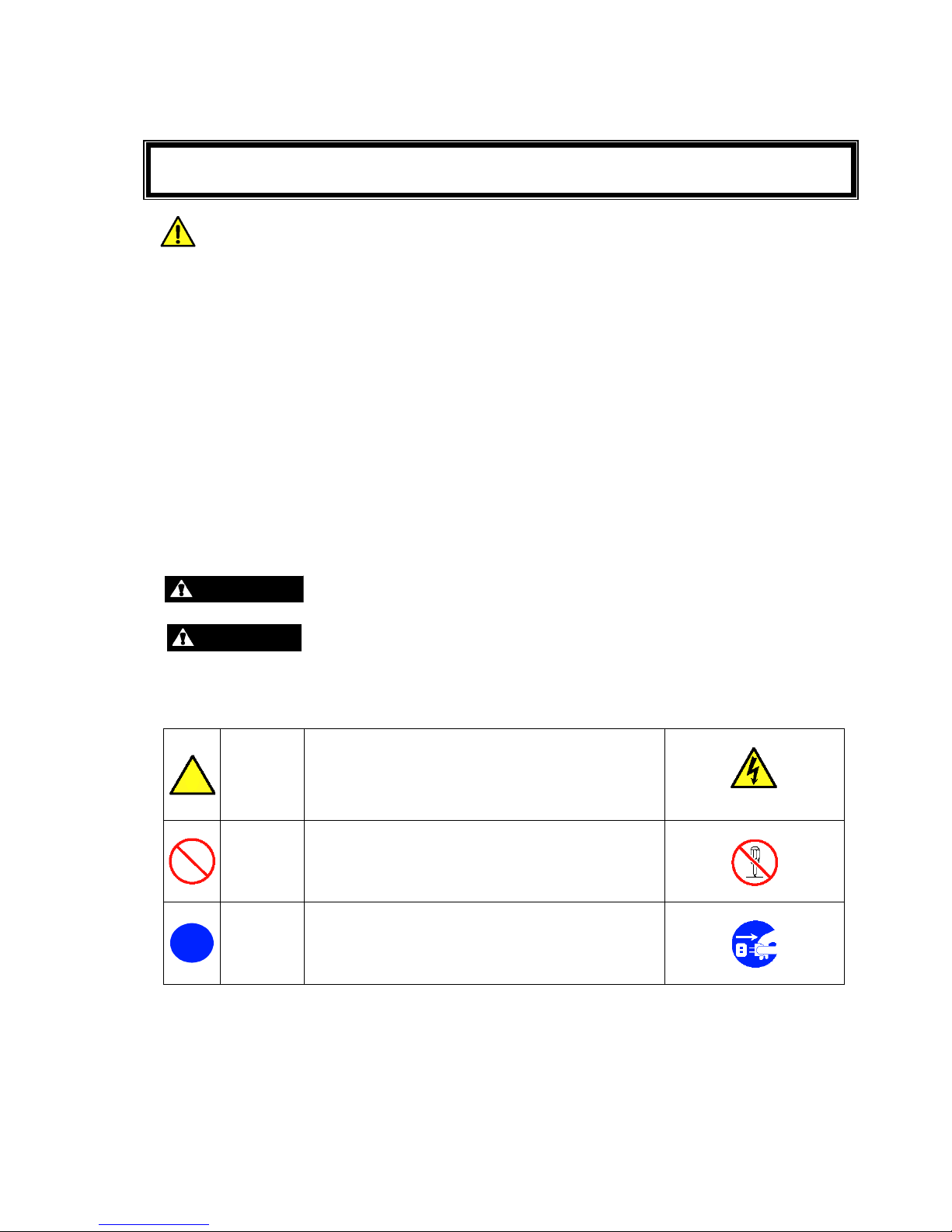
Attention
This symbol indicates the presence of a hazard.
An image in the symbol illustrates the hazard type.
(Example)
Precaution against electric
shock
Prohibited
Action
This symbol indicates prohibited actions. An image
in the symbol illustrates a particular prohibited
action.
(Example)
Prohibition of disassembly
Mandatory
Action
This symbol indicates mandatory actions. An image
in the symbol illustrates a mandatory action to avoid
a particular hazard.
(Example)
Unplug the power cord!
Page 4
ii
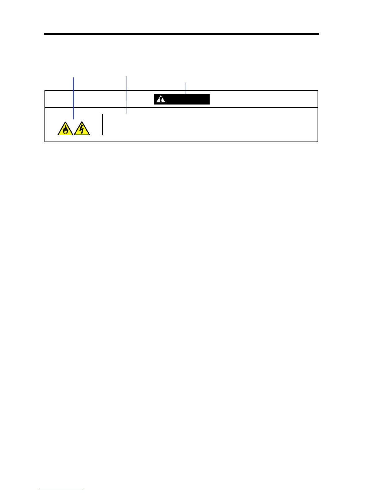
(Example)
Symbol to draw attention Description of a danger
Term indicating a degree of danger
WARNING
Plug in to a proper power source.
Use a wall outlet of specified voltage. Use of an improper power source may
cause a fire or a power leak.
Page 5
iii
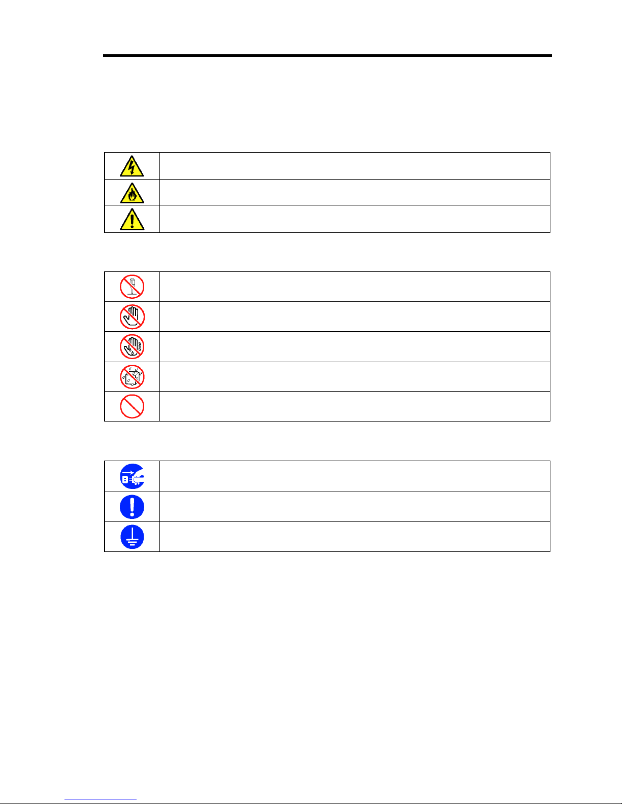
SYMBOLS USED IN THIS MANUAL AND WARNING LABELS
Attentions
Indicates that improper use may cause an electric shock.
Indicates that improper use may cause fumes or fire.
Indicates a general notice or warning that cannot be specifically identified.
Prohibited Actions
Do not disassemble, repair, or modify the US110. Otherwise, an electric shock or fire
may be caused.
Do not touch the component specified. Otherwise, an electric shock or burn may be
caused.
Do not touch the US110 components with wet hand. Otherwise, an electric shock may
be caused.
Keep water or liquid away from the US110. Otherwise, an electric shock or a fire may
be caused.
Indicates a general prohibited action that cannot be specifically identified.
Mandatory Action
Unplug the power cord of the US110. Otherwise, an electric shock or fire may be
caused.
Indicates a mandatory action that cannot be specifically identified. Make sure to follow
the instruction.
Be sure to provide earthing. Otherwise, an electric shock or fire may be caused.
Page 6
iv
Safety Notes
This section provides notes on using your US110 safely. Read this section carefully to ensure proper
and safe use of the US110. For symbols, see "SAFETY INDICATIONS" provided earlier.
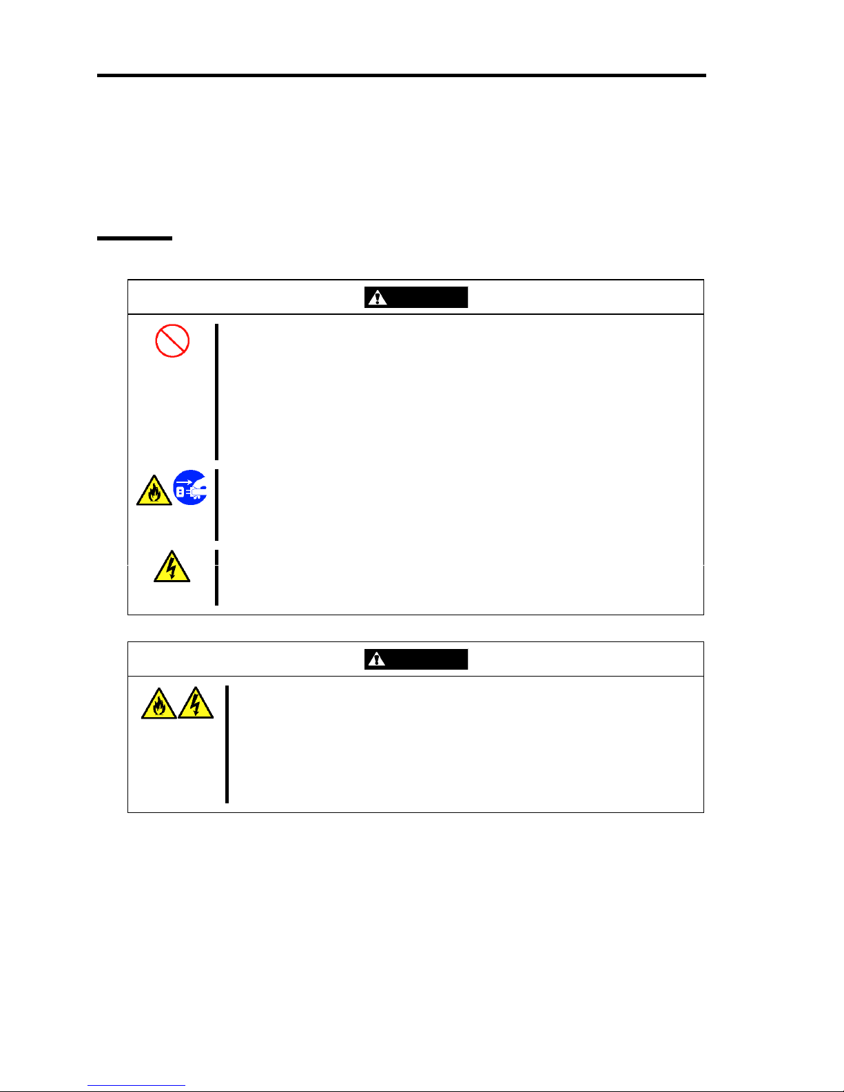
General
WARNING
Do not use the US110 for services where critical high availability may directly
affect human lives.
Your US110 is not intended to be used with or control facilities or devices
concerning human lives, including medical devices, nuclear facilities and
devices, aeronautics and space devices, transportation facilities and devices;
and facilities and devices requiring high reliability. NEC assumes no liability for
any accident resulting in personal injury, death, or property damage if the
US110 has been used in the above conditions.
Do not use the US110 if any smoke, odor, or noise is present.
If smoke, odor, or noise is present, immediately turn off the US110 and
disconnect the power plug from the outlet, then contact your service
representative. Using the US110 in such conditions may cause a fire.
Keep needles or metal objects away from the US110.
Do not insert needles or metal objects into the US110. Doing so may cause an
electric shock.
CAUTION
Keep water or foreign matter away from the US110.
Do not let any form of liquid (water etc.) or foreign matter (e.g., pins or paper
clips) enter the US110. Failure to follow this warning may cause an electric
shock, a fire, or a failure of the US110. When such things accidentally enter
the US110, immediately turn off the power and disconnect the power plug
from the outlet. Do not disassemble the US110. Contact your service
representative.
Page 7
v
Power Supply and Power Cord Use
WARNING
Do not hold the power plug with a wet hand.
Do not disconnect/connect the plug while your hands are wet. Failure to
follow this warning may cause an electric shock.
CAUTION
Plug in to a proper power source.
Use a wall outlet of specified voltage. Use of an improper power source may
cause a fire or a power leak.
Do not install the US110 where you need an extension cord. Use of a cord
that does not meet the power specifications of your US110 may heat up the
cord and cause a fire.
Do not connect the power cord to an outlet that has an illegal number of
connections.
The electric current exceeding the rated flow overheats the outlet, which may
cause a fire.
Insert the power plug into the outlet as far as it goes.
Heat generation resulting from a halfway inserted power plug (imperfect
contact) may cause a fire. Heat will also be generated if condensation is
formed on dusty blades of the halfway inserted plug, increasing the possibility
of fire.
Use the authorized power cord only.
Use only the power cord that comes with your US110. Use of an unauthorized
power cord may cause a fire when the electric current exceeds the rated flow.
Also, observe the following to prevent an electric shock or fire caused by a
damaged cord.
■ Do not stretch the cord harness.
■ Do not bend the power cord.
■ Do not twist the power cord.
■ Do not step on the power cord.
■ Do not bundle power cords.
■ Do not pinch the power cord.
■ Keep chemicals away from the power cord.
■ Do not place any object on the power cord.
■ Do not alter, modify, or repair the power cord.
■ Do not secure the power cord with staples or equivalents.
■ Do not use any damaged power cord. (Replace a damaged power cord
with a new one of the same specifications. Ask your service representative
for replacement.)
Page 8
vi
CAUTION
Do not use the attached power cord for any other devices or usage.
The power cord that comes with your US110 is designed aiming to connect
with this US110, and its safety has been tested. Do not use the attached
power cord for any other purpose. Doing so may cause a fire or an electric
shock.
Do not pull the cord harness to disconnect the power cord.
Hold the connector of the power cord and pull it straight. Pulling the cord
harness or applying excess force to the connector may cause a damage to
the cable, resulting in a fire or an electric shock.
Installation, Relocation, Storage, and Connection
CAUTION
Do not install the US110 in any place other than specified.
Do not install the US110 in the following places or any place other than
specified in this User's Guide. Failure to follow this instruction may cause a
fire.
■ a dusty place
■ a humid place such as near a boiler
■ a place exposed to direct sunlight
■ an unstable place
Do not use the US110 in the place where corrosive gases exist.
Make sure not to locate or use the US110 in the place where corrosive gases
(sulfur dioxide, hydrogen sulfide, nitrogen dioxide, chlorine, ammonia, ozone,
etc.) exist.
Also, do not place it in the environment where the air (or dust) includes
components accelerating corrosion (ex. sulfur, sodium chloride) or conductive
metals. There is a risk of a fire due to corrosion and shorts of an internal
printed board. Consult with your service representative for a place
appropriate to US110.
Page 9
vii
Cleaning and Working with US110
WARNING
Do not disassemble, repair, or alter the US110.
Never attempt to disassemble, repair, or alter the US110 on any occasion
other than described in this manual. Failure to follow this instruction may
cause an electric shock or fire as well as malfunctions of the US110.
Disconnect the power plug before accessing inside the US110.
Make sure to power off the US110 and disconnect the power plug from a
power outlet before cleaning. Touching the inside of US110 with its power
cord connected to a power source may cause an electric shock even of the
US110 is off-powered.
Disconnect the power plug from the outlet occasionally and clean the plug
with a dry cloth. Heat will be generated if condensation is formed on a dusty
plug, which may cause a fire.
During Operation
WARNING
Avoid contact with the US110 during thunderstorms.
Disconnect the power plug from the outlet when a thunderstorm is
approaching. If it starts thundering before you disconnect the power plug, do
not touch any part of the US110 including the cables. Failure to follow this
warning may cause a fire or an electric shock.
Keep animals away from the US110.
Failure to follow this warning may cause a fire or an electric shock.
Page 10

viii
For Proper Operation
Observe the following notes for successful operation of the US110. Use of the US110 ignoring the
notes will cause malfunctions or failures of the US110.
When you have just turned off the US110, wait at least 10 seconds before turning it back
on. If the US110 is connected to the UPS, set at least 10 seconds delay in the power-on
schedule.
Turn off the power of US110 and unplug the power cord from the outlet before relocating
the US110.
Clean the US110 on a regular basis. Regular cleaning proactively prevents various failures
of the US110.
Lightning may cause a momentary voltage drop. To prevent this problem, it is
recommended to use of an uninterruptible power supply unit.
It is recommended that the US110 should be stored in a place where the room temperature
can be maintained.
Store the US110 under the storage condition (temperature: –20°C to 60°C, humidity: 20%
- 80%, without condensation).
Turn off the cellular phone or pager around the US110. Radio interference may cause
malfunctions of the US110.
The US110 uses natural convection for discharging heat. Therefore, do not put any object
on the US110, or place the US110 close to any other object.
Observe the following notes on using and connecting an interface cable.
– Do not use any damaged cable connector.
– Do not step on the cable.
– Do not place any object on the cable.
– Do not use the US110 with loose cable connections.
– Do not use any damaged cable.
Page 11

ix
Restricted Features
Keep in mind the following functional specifications before using the US110.
To use window display feature of US110 to the maximum extent, be sure to select High
Colors (16 bits) for window display of US110 and connection settings. The window
operation may become slow if you use the high-speed animation feature in full color
mode.
If a firewall is installed between the US110 and the virtual PC and you want to use the
high-speed animation feature, you need to open the specific port. For more information,
see "Readme" document in high-speed animation module.
The high-speed animation feature is unavailable for the Citrix Presentation Server.
Features for Future Enhancement
This User's Guide includes descriptions about the following features. However, their operations are
not yet guaranteed now. These features are reference only for future enhancement.
Dial-up, PPPoE, PPTP, and Serial Communication
"Notifications" in [Volume & Sounds Properties]
"Advanced Adapter Settings" in [Network and Dial-up Connection]
"Customize" in [Regional and Language Settings]
Page 12

x
Preface
Congratulations on the purchase of your US110.
The US110 is a Thin Client terminal to be connected with the virtual PC of NEC product.
Read this User's Guide thoroughly to fully understand handling of the US110 and appreciate its
functions to the maximum extent.
About This Guide
This manual is a guide for proper setup and use of your US110. This manual also covers useful
procedures for dealing with difficulties and problems that may arise during setup or operation of
your US110.
Keep this manual for future use.
Text Conventions
The following conventions are used throughout this User's Guide. For safety symbols, see
"SAFETY INDICATIONS" provided earlier.
IMPORTANT:
Items that are mandatory or require attention when using the US110
NOTE:
Helpful and convenient piece of information
Page 13

xi
Organization of this Guide
This User's Guide has four chapters. Each chapter covers information as shown below.
IMPORTANT: Read "NOTES ON SAFETY" first.
Be sure to read "NOTES ON SAFETY" described at the top of this
User's Guide before this section. "NOTES ON SAFETY" include
important points on operating the US110 safely and correctly.
Chapter 1 About US110
tells you how to install, connect, and shutdown your US110.
Chapter 2 Using Features of US110
tells you how to use control panel, define system preferences, and configure the network.
Chapter 3 Advanced Settings of US110
tells you how to use advanced features of US110.
Chapter 4 Maintenance
provides you with all the information necessary to maintain successful operation of the
US110. This chapter also includes helpful information for solving problems that might
occur with your system.
Page 14

xii
In the Package
The shipping carton contains various accessories, as well as the product itself. See the packing list
to make sure that you have everything and that individual components are not damaged. If you find
any component missing or damaged, contact your service representative.
Transfer to Third Party
Make sure to provide this guide and all the accessories along with the product to a third party.
Disposal
Dispose of the US110 and all the option devices according to all national laws and
regulations. Also, dispose of the power cord provided with the US110 to avoid diversion
to some other devices.
IMPORTANT: If data remains on the USB media or other writable
media (such as CD-R and CD-RW), it could be restored and reused by
outsiders. The user is responsible for erasing completely such data
before disposal. You need to exercise sufficient care to protect privacy
and confidential information.
Page 15

xiii
Contents
NOTES ON SAFETY - Always read the Notes -.............................................i
Safety Notes ..................................................................................................................... iv
General ....................................................................................................................................... iv
Power Supply and Power Cord Use ............................................................................................v
Installation, Relocation, Storage, and Connection......................................................................vi
Cleaning and Working with US110...........................................................................................vii
During Operation ......................................................................................................................vii
For Proper Operation...................................................................................................... viii
Restricted Features ..................................................................................................................... ix
Features for Future Enhancement...............................................................................................ix
Preface................................................................................................................................x
About This Guide ...............................................................................................................x
Text Conventions......................................................................................................................... x
Organization of this Guide ......................................................................................................... xi
In the Package ................................................................................................................. xii
Transfer to Third Party .................................................................................................... xii
Disposal........................................................................................................................... xii
Chapter 1 About US110 .......................................................................................1
Names and Functions of Components................................................................................1
Front View...................................................................................................................................1
Rear View....................................................................................................................................2
Installation and Cable Connection .....................................................................................3
Installation...................................................................................................................................3
Connecting with Network ...........................................................................................................7
Using US110 ......................................................................................................................9
System Configuration.................................................................................................................. 9
Basic Operations of US110 .......................................................................................................15
Configuring Network ................................................................................................................ 16
Setting Display Resolution........................................................................................................ 17
Configuring Connection for Virtual PC..................................................................................... 18
Connecting to Virtual PC .......................................................................................................... 19
Logoff from Virtual PC ............................................................................................................. 20
Shutdown of US110 ..................................................................................................................21
Chapter 2 Using Features of US110.................................................................23
Using Terminal Connection Manager........................................................................................ 23
Configuring ICA and RDP Connections ...................................................................................25
Using Control Panel ..................................................................................................................33
Keyboard................................................................................................................................... 36
Mouse........................................................................................................................................37
Display ...................................................................................................................................... 38
Page 16

xiv
Volume & Sounds Properties.....................................................................................................42
Date/Time Properties.................................................................................................................44
Network.....................................................................................................................................45
Printers.......................................................................................................................................46
Regional and Language Settings ...............................................................................................59
Terminal Server Client Licenses................................................................................................60
System Properties ......................................................................................................................61
Certificates.................................................................................................................................65
Global ICA Client Settings........................................................................................................68
Network Utilities .......................................................................................................................73
SNTP .........................................................................................................................................75
Update .......................................................................................................................................76
File Upload................................................................................................................................81
Log-on Settings .........................................................................................................................83
USB Storage Device Settings ....................................................................................................86
Settings Initialization.................................................................................................................87
Set Administrator Password.......................................................................................................88
Setting User Mode.....................................................................................................................89
Switch to User Mode .................................................................................................................91
Shutdown Settings.....................................................................................................................92
SSC Agent .................................................................................................................................93
Application Installer ..................................................................................................................94
Logging .....................................................................................................................................96
Error Reporting..........................................................................................................................98
Display Resolution Settings.....................................................................................................100
Network Link Configuration ...................................................................................................102
Chapter 3 Using Advanced Features ............................................................ 103
Logon to Terminal Connection Manager.................................................................................103
Automatic Reconnection Feature of Connection Entry...........................................................107
Administrator Mode and User Mode on Control Panel...........................................................110
Software Update ...................................................................................................................... 111
Software Update ...................................................................................................................... 116
VPN Connection......................................................................................................................117
Screen Capture of US110 ........................................................................................................123
Setting RDP Encryption Level ................................................................................................124
Chapter 4 Maintenance................................................................................... 125
Troubleshooting............................................................................................................. 125
Problem with US110 ...............................................................................................................125
Problems with Logon to Terminal Connection Manager.........................................................125
Problem with RDP/ICA/SNTP Connections ...........................................................................125
Problem when Using a Combination of Multiple Thin Clients ...............................................126
Problems with Video Acceleration ..........................................................................................126
Problems with Update .............................................................................................................126
Problems with USB Device.....................................................................................................127
Problems with Shutdown Settings...........................................................................................127
Page 17

xv
Problems with Settings Initialization.......................................................................................128
Problems with Ports used in US110 ........................................................................................128
Setting change while configuring [Auto Start] of connection entry
and [Power Off] of logoff operation........................................................................................ 129
About US110 Network Speed ................................................................................................. 129
Problems with Update ............................................................................................................. 130
About Software Phone in VPN Connection ............................................................................ 130
Problems with Connection to Citrix’s XenApp....................................................................... 131
Problems with Screen Resolution Setting ............................................................................... 131
Problems with Sound ..............................................................................................................131
Problem with Mouse Pointer................................................................................................... 131
Problem with Icons on Control Panel......................................................................................132
Problem with Device Connection............................................................................................132
Cleaning .........................................................................................................................133
Cleaning the Keyboard/Mouse................................................................................................ 133
Appendix A Specifications..............................................................................135
Appendix B Enhancements/Fixes..................................................................137
March 2009 Version – Enhancements & Fixes .......................................................................137
January 2009 Version – Enhancements & Fixes .....................................................................139
September 2008 Version - Enhancements & Fixes..................................................................141
March 2008 Version - Enhancements & Fixes ........................................................................ 143
December 2007 Version - Enhancements & Fixes .................................................................. 145
Page 18

xvi
(This page is intentionally left blank.)
Page 19
Chapter 1
About US110
This chapter describes how to install, connect, and shutdown the US110.
Names and Functions of Components
Names and functions of components are described below. Any other components than described
here are not used in the US110.
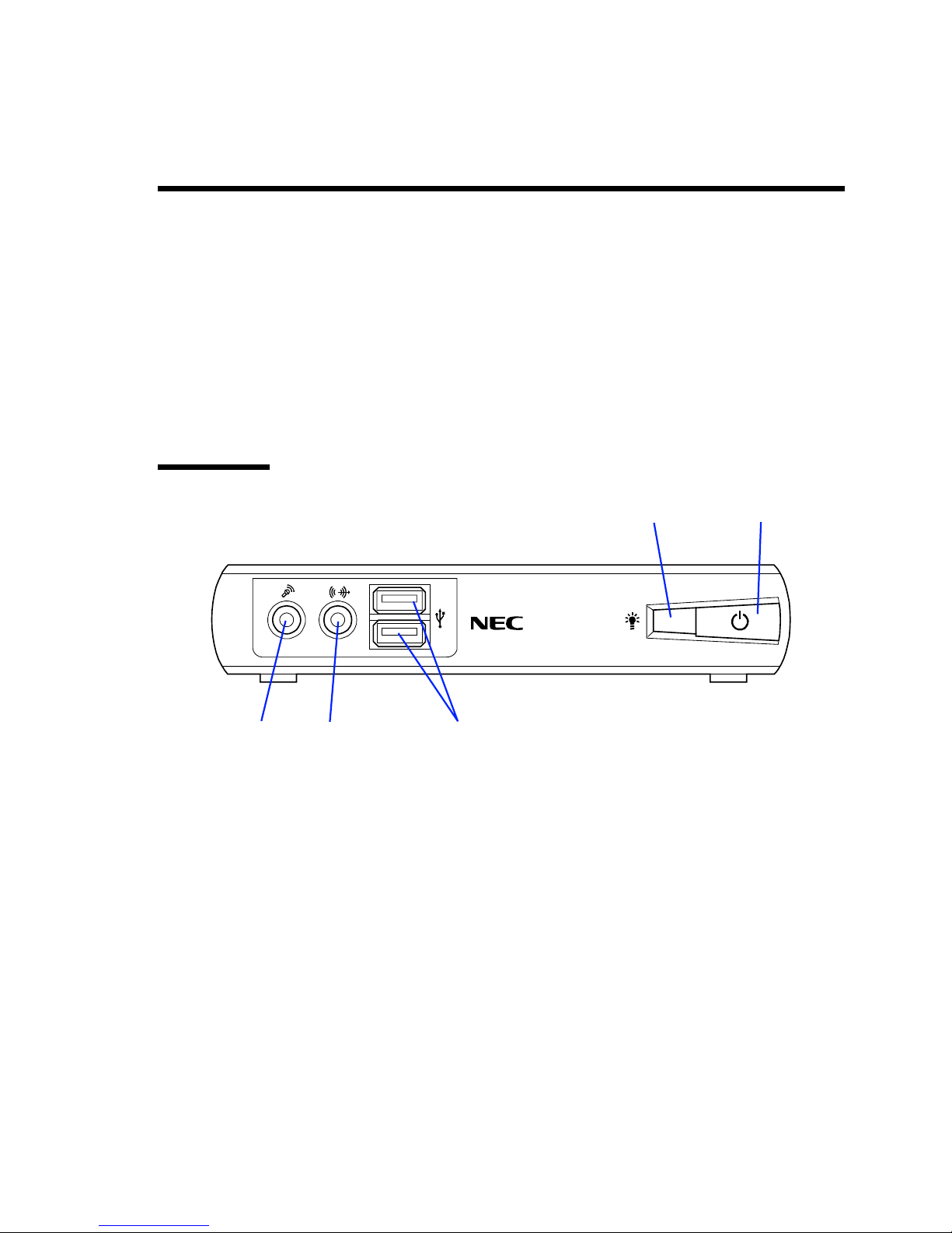
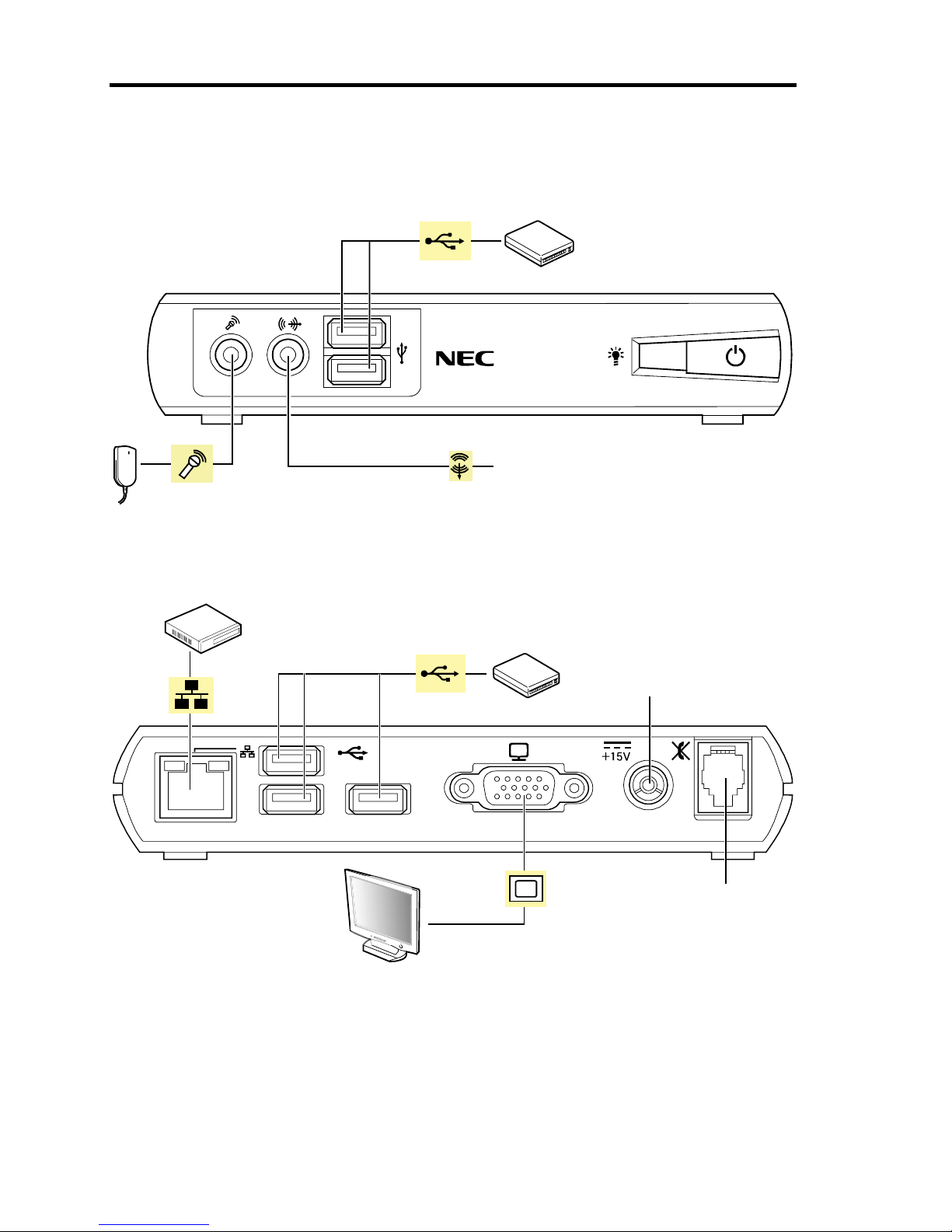
Front View
1 POWER lamp (green/amber)
Lights in green while the US110 is powered on.
Lights in amber while the US110 is in power-saving mode.
2 POWER switch
Press this switch to power on/off the US110. Pressing this switch once lights the POWER lamp
to indicate the US110 is powered. Pressing it again causes the shutdown confirmation
message to appear. To shutdown the US110 forcibly, press and hold this switch for at least four
seconds.
3 USB connector
Connect a device having the USB interface to this connector.
4 LINE-OUT connector
Connect a device having the LINE-IN terminal (such as headphone or PC speaker) to this
connector.
5 Microphone connector
Connect a microphone to this connector.
1
345
2
Page 20
2 About US110
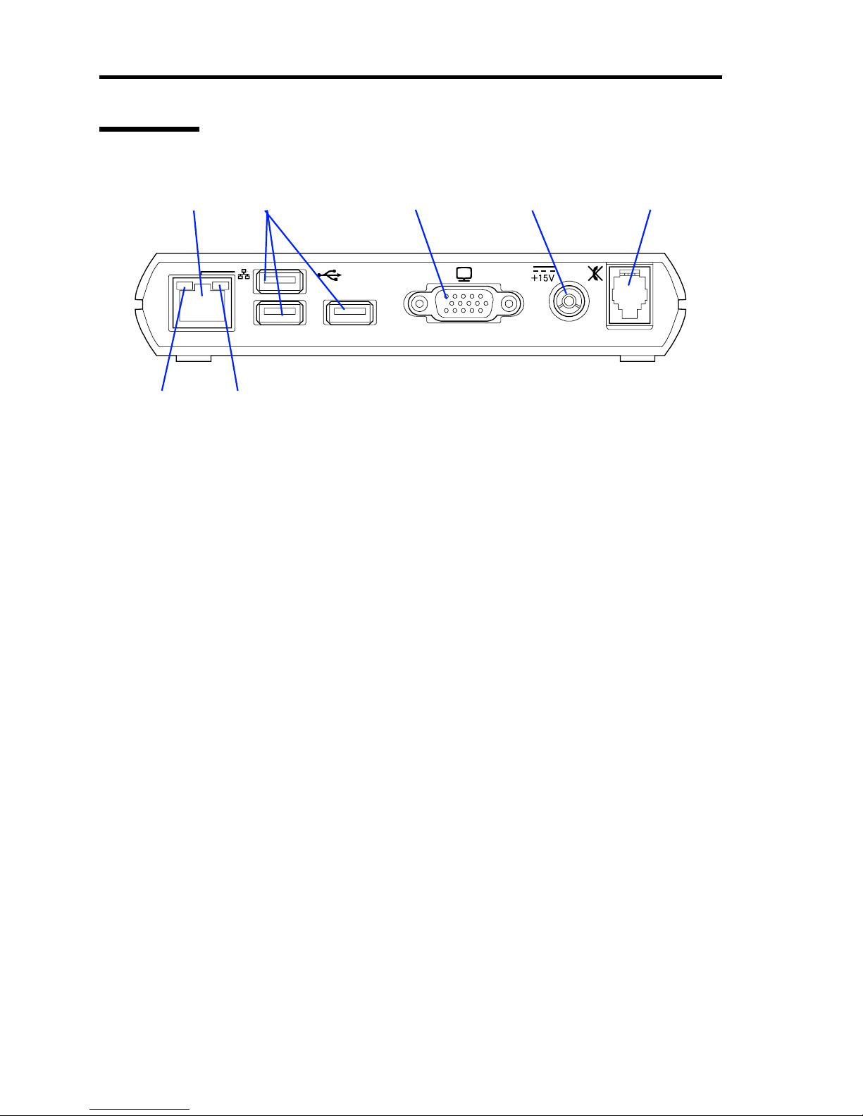
Rear View
1 LAN connector
Connect with a network system on LAN. Supports 1000BASE-T/100BASE-TX/10BASE-T
network subsystem.
2 USB connector
Connect a device having the USB interface to this connector.
3 Monitor connector
Connect a display unit to this connector.
4 Power connector (15 V)
Connect the provided AC adapter to this connector.
5 RJ-22 connector
Connect a headset or handset to this connector.
6 ACT lamp (green)
Blinks while the port is active.
7 SPEED lamp (yellow/green)
Indicates the data transfer rate of network port.
12 3 4 5
67
Page 21
About US110 3
Installation and Cable Connection
This section describes installation and cable connection of the US110.
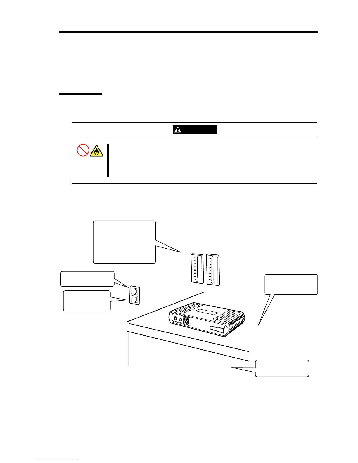
Installation
To use the US110, install it on a desk.
CAUTION
Observe the following instructions to use the US110 safely. Failure to follow
these instructions may cause a fire, personal injury, or property damage. See
pages i to ix for details.
■ Do not install the US110 in any place other than specified.
The following figure illustrates a site suitable for installing the US110.
* It is recommended that the US110 should be used in a room where temperature is in
the range between 15 to 25ºC.
Clean and tidy room
Install the US110 on the
rigid, flat desk.
Close enough to
connect the power
cord
Grounded parallel bipolar power outlet
Environmental requirements
for operation
<Operating>
Temperature: 10 to 35ºC
Humidity: 20 to 80%
<Halting>
Temperature: –20 to 60ºC
Humidity: 20 to 80%
Page 22

4 About US110
Do not place the US110 in the following places. Placing the US110 in such places may cause
malfunctions of the US110.
Places with drastic changes in temperature (e.g., near a heater, air conditioner, or
refrigerator)
Places with strong vibration
Places where corrosive gases (sulfur dioxide, hydrogen sulfide, nitrogen dioxide, chlorine,
ammonia, ozone, etc) exist. Also, the place where the air (or dust) includes components
accelerating corrosion (ex. sulfur, sodium chloride) or conductive metals.
Place where chemicals are nearby, or chemicals may be sprayed accidentally.
On a non-antistatic carpet
Places with possibilities of falling objects
Places where the power cord or interface cable may be stepped on or stumbled
Places near a device generating intense magnetic field (such as a TV, radio,
broadcast/communication antenna, power transmission wire, and electromagnetic crane)
(If unavoidable, contact your service representative to request proper shield construction.)
Places where a power outlet that shares the ground line with another (especially the one to
which a device with large power consumption is connected) must be used for the US110
Places near equipment that generates power noise (e.g., contact spark at power-on/power-
off of commercial power supply through a relay). (To install the US110 near equipment
that generates power noise, ask your service representative for separating the power
wiring or installing a noise filter.)
Page 23
About US110 5
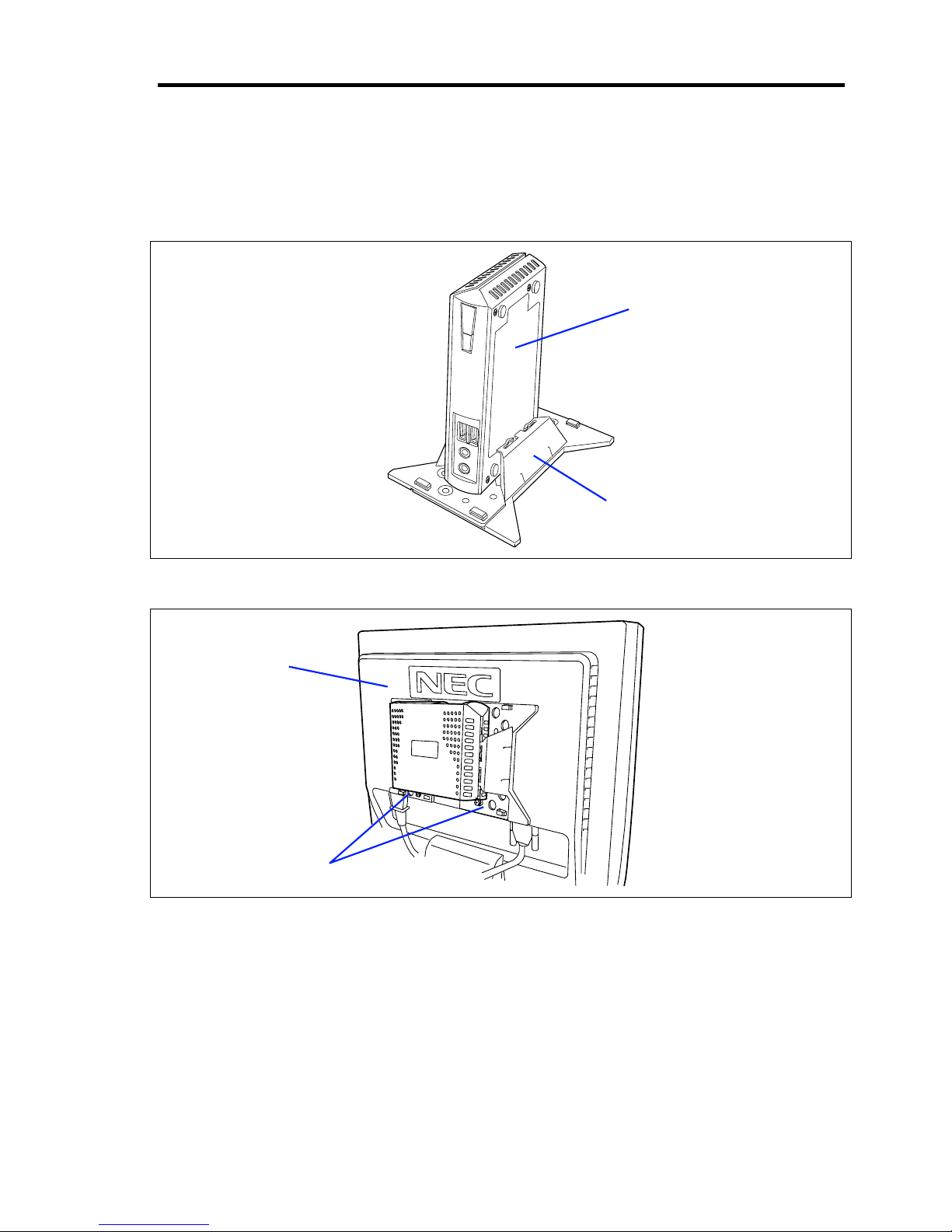
Installation by Using N8120-102 Desk/LCD Mount Kit (Option)
Refer to the manual provided with N8120-102 Desk/LCD Mount Kit for how to install the US110
by using an optional Desk/LCD Mount Kit N8120-102.
Installing US110 on a desk by using N8120-102 as a pedestal
Installing US110 on rear of LCD unit by using N8120-102 as an LCD bracket
US110
Desk/LCD Mount Kit
US110
Desk/LCD Mount Kit
Page 24

6 About US110
Installation by Using N8120-103 LCD Mount Adjuster Option
To install the US110 on the desired location of rear of the LCD unit, use the N8120-103 LCD
Mount Adjuster Option.
Refer to the manual provided with N8120-103 LCD Mount Adjuster Option for how to install the
US110 by using an optional LCD Mount Adjuster N8120-103.
IMPORTANT: When installing US110 by using N8120-103 Mount
Adjuster Option, an optional N8120-102 Desk/LCD Mount Kit is also
required.
US110
LCD Mount
Adjuster Option
Desk/LCD
Mount Kit
Page 25
About US110 7
Connecting with Network
Connect US110 with the network.
First connect the network cable, connect the provided power cord of the AC adapter to the US110,
and then connect the power plug to the power receptacle.
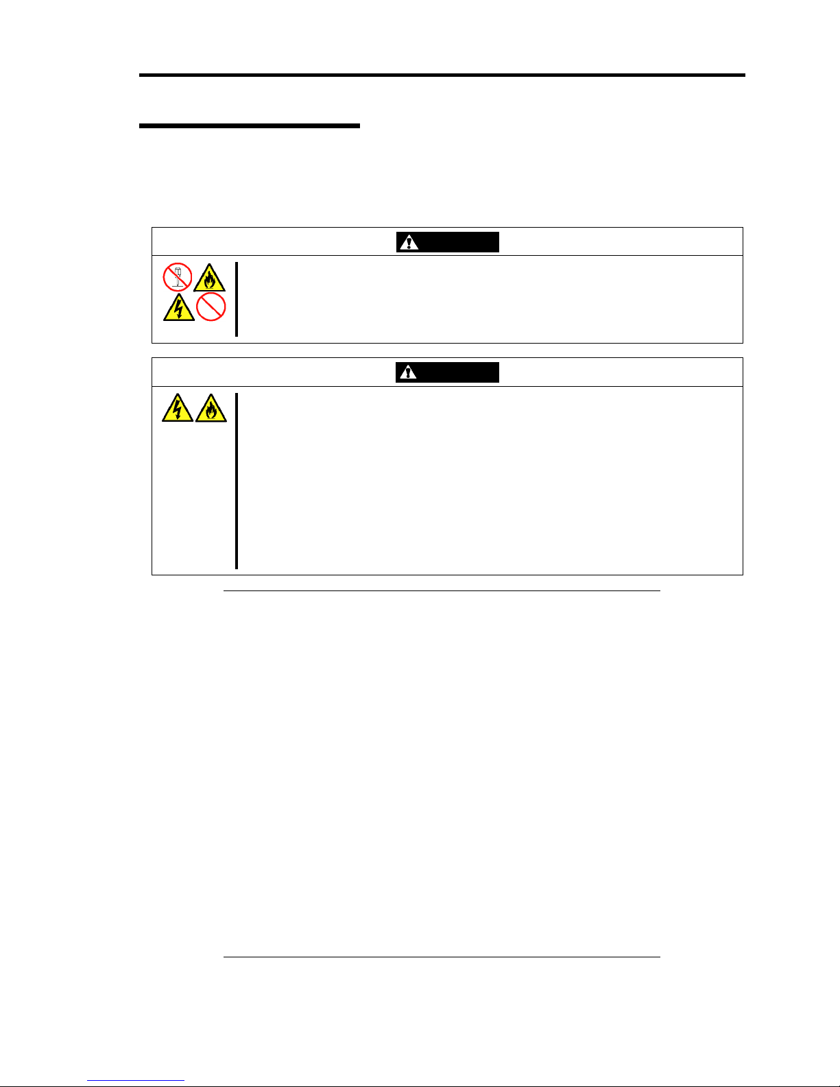
WARNING
Observe the following instructions to use the US110 safely. Failure to follow these
instructions may result in death or serious personal injury. See pages i to ix for
details.
■ Do not hold the power plug when your hands are wet.
CAUTION
Observe the following instructions to use the US110 safely. Failure to follow these
instructions may cause a fire, personal injury, or property damage. See pages i to ix
for details.
■ Plug into a proper power source of the specified voltage.
■ Do not connect the power cord to an outlet that has an illegal number of
connections.
■ Do not use the US110 with any loose interface connection.
■ Use the authorized power cord only.
■ Do not connect any interface cable with the power cord of the US110 being
connected to a power source.
■ Do not use any unauthorized interface cable.
IMPORTANT:
Power off the US110 and a peripheral device before connection.
Connecting a powered peripheral device to the powered US110 will
cause malfunctions and failures.
To connect a third-party peripheral device or interface cable to the
US110, consult with your service representative for availability of
such a device or cable. Some third-party devices may not be used
for the US110.
When disconnecting the cable from LAN connector, it is hard to
push the catch of the connector with your finger. Disconnect the
connector pushing the catch with a standard screwdriver. At this
time, be very careful for the screwdriver not to damage the LAN
connector or other connectors.
Do not connect any other peripheral devices than specified by NEC
to the RJ-22 connector on the rear of the US110. RJ-22 is used to
connect with the headset.
Do not connect any leased line to the RJ-22 connector on the rear of
the US110. RJ-22 is used to connect with the headset.
Power off the US110 before you connect or disconnect the USB
handset. Otherwise, the system may halt and you need to reboot the
US110.
Page 26
8 About US110
Secure the power cord(s) and interface cables with a tie wrap.
USB device
USB Handset
Headphone or PC speaker
Microphone
FRONT
Hub (multi-port repeater)
USB device
AC adapter
Handset or
Headset
Display unit
REAR
Page 27

About US110 9
Using US110
This section describes system configuration, basic operations, connection to virtual PC, and
shutdown of US110.
System Configuration
NOTE: In the system configuration shown below, descriptions for
network devices such as hub and router are omitted.
The US110 is a Thin Client terminal to be connected to virtual PC.
The minimum system configuration of Thin Client system requires a single US110 and a virtual PC
(see "Standard Configuration").
Adding DHCP server and download server (FTP and HTTP server) to the standard configuration
can improve maintainability of Thin Client system (see "Extension 1").
An extended configuration allows you to use SSC (the management tool for VPCC) (see Extension
3).
In addition, you can use VPN for network environment to connect with virtual PC (see "VPN").
Page 28
10 About US110
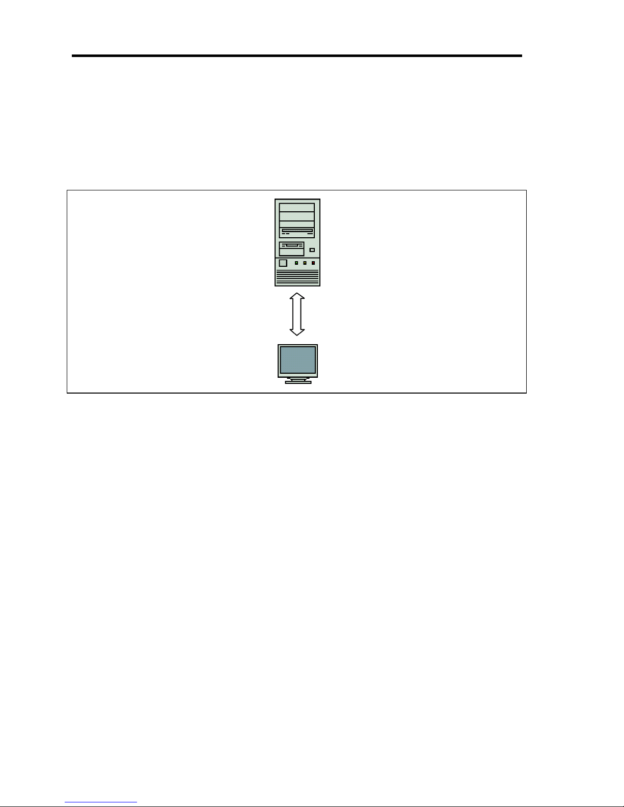
Standard Configuration
The minimum configuration of Thin Client system requires a single US110 and a server that hosts
virtual PC.
Configure network as the default of US110, and specify destination port of virtual PC using
Terminal Connection Manager. Then, you are ready to connect with the virtual PC.
Figure 1-1 Standard Configuration
VPCC (Virtual PC Center)
VPCC is a server that hosts the virtual PC. Windows XP Professional is used as a virtual
PC. The US110 supports connection to Windows Server 2003 and Citrix Presentation
Server 4.5, in addition to VPCC.
High-speed animation feature
To use high-speed animation feature, the relevant module for US110 must be installed on
virtual PC. This feature is supported by Windows Media Player (Version 10 or 11).
VPCC
US110
Page 29
About US110 11
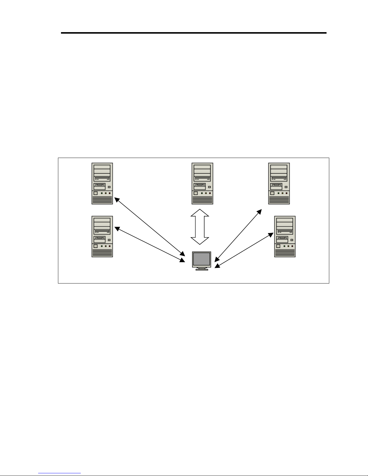
Extension 1
Adding DHCP server and download server (FTP and HTTP server) to the standard configuration
can improve maintainability of Thin Client system.
US110 can obtain the settings information and connection information from DHCP and download
server (FTP or HTTP server).
With the network using DHCP server, the DHCP option information can be set for US110. By
distributing the setting information for US110 to download server, several US110s can be
configured concurrently, not individually.
US110 does not retain system clock when it is off-powered. To adjust the system clock of US110 at
next startup, use the SNTP server to synchronize the clock.
Figure 1-2 Extension 1
VPCC (Virtual PC Center)
DHCP server
The DHCP server is used to obtain IP address of US110. Also, you can obtain information
about download server (FTP and HTTP server) to be used.
SNTP server
Setting information of SNTP server in US110 allows you to synchronize the system time.
FTP server (Download server/Upload server)
US110 can obtain the settings information of US110 system and connection list of virtual
PC from the download server and use them. In addition, update version of US110
software can also be obtained from the download server.
Using File Upload feature of US110, settings information (common.txt) and connection
list of virtual PC (username.txt) that is created on a single US110 can be uploaded to FTP
server.
DHCP server
SNTP server
VPCC FTP server
HTTP server
US110
Page 30

12 About US110
HTTP server (Download server)
You can use HTTP server as a download server for US110.
US110 can obtain the settings information of US110 system and connection list of virtual
PC from the download server and use them. In addition, update version of US110
software can also be obtained from the download server.
NOTES:
Use FTP or HTTP protocol for communication with download
server. No other protocol such as HTTPS cannot be used.
FTP server can be used as both download and upload server for
US110. HTTP server can only be used as download server for
US110.
Page 31

About US110 13
Extension 2
Linking US110 with SSC (the management tool for VPCC) can enhance maintainability of Thin
Client system. US110 supports Client Management Option (CMO) and agent feature of DPM for
linkage with SSC.
NOTE: DPM is supported VPCC 2.0 or later.
Figure 1-3 Extension 2
VPCC (Virtual PC Center)
DHCP server
You can obtain IP address of US110 and other configuration information from the DHCP
server.
With DHCP option setting, the server address of CMO Manager can be obtained
automatically.
PVM (Provisioning Manager)
PVM manages the virtual PC running on VPCC. CMO Manager works with PVM.
CMO Manager
CMO Manager is a server feature of client management option. CMO Manager totally
manages virtual PCs connected with US110. With client management option, the user can
connect with virtual PC by selecting an available virtual PC from the list.
DHCP server
CMO Manager PVM
US110
VPCC
Page 32

14 About US110
VPN
You can use VPN as a network environment that connects with virtual PC.
Figure 1-4 VPN
VPCC (Virtual PC Center)
VPN GW
US110 can use L2TP as a protocol for VPN. Specify L2TP at VPN gateway to which
US110 connect with.
Authentication server
Authentication server certifies the connected user responding with the request from VPN
GW. Enter the account to be sent to Authentication server on US110.
US110
VPCC
VPN GW
Authentication
server
Page 33

About US110 15
Basic Operations of US110
US110 is a thin client terminal to be connected with virtual PC. Thus, US110 is designed to
minimize its setup procedure and operation.
Basic operations of US110 are performed on Terminal Connect Manager that has menus for
connecting to virtual PC and on Control Panel of US110.
Power on US110
Te r m i n al C o n n e c t i on
Manager
Control
Panel
Shutdown
US110
Use virtual PC desktop
(Connect with virtual PC)
Figure 1-5 Basic Operations of US110
US110 uses Terminal Connection Manager that has menus for connecting to virtual PC.
Use the address of virtual PC and connection information that are assigned by the system
administrator, and set them in [Configure] tab page of Terminal Connection Manager. Saving the
configured connection entry and specifying it as startup menu allows you to connect with virtual PC
automatically when US110 is powered.
To modify configuration of US110, use the Control Panel. You can open the Control Panel from the
Terminal Connection Manager.
The system administrator can determine the number of icons to be displayed on Control Panel and
whether to display [Configure] tab on Terminal Connection Manager or not appropriately to users.
At the first startup of US110, initial settings are applied. Name of each US110 is assigned by default,
and the network is configured initially to obtain the network address from the DHCP server. If you
do not need to modify the initial settings, use the Control Panel as is. You can connect with virtual
PC from the Terminal Connection Manager.
At the second and the subsequent startup of US110, according to setup made by system
administrator, reading configuration information of US110 or displaying of Log-on dialog box for
obtaining connection destination of virtual PC are performed before the Terminal Connection
Manager appears.
To minimize operations on US110 helps you to understand thin client system and enables simple
and easy operation.
Page 34

16 About US110
Configuring Network
By the default setting of US110, the network is configured initially to obtain the IP address from the
DHCP server. If you want to change configuration, take the following steps.
1. On the Terminal Connection Manager, click the [Control Panel] button to open the
Control Panel window.
2. Double click [Network and Dial-up Connection].
3. Double click [NETCLIENT-NSS].
4. Select [Specify an IP address], then enter addresses for IP Address, Subnet Mask, and
Default Gateway. For settings of DNS and WINS, use the [Name Servers] tab.
NOTE: The [Control Panel] button does not appear on [Configure] tab
of Terminal Connection Manager. It appears when you select the
[Connections] tab.
Page 35

About US110 17
Setting Display Resolution
Set resolution appropriate to your display unit.
1. On the Terminal Connection Manager, click [Control Panel] to open the Control Panel
window.
2. Double click the [Display Resolution Settings] icon.
3. In the [Display settings] frame, choose an appropriate values for [Display resolution] and
[Screen color] from the pulldown menu.
4. Click [OK] to close the window. The US110 will reboot with the specified resolution.
NOTE: If you check to [Activate DDC], the optimum display settings
can be obtained, if your display unit supports DDC.
To use window display feature of US110 to the maximum extent, it is
recommended to select High Colors (16 bits) for window display of
US110 and virtual PC.
Page 36

18 About US110
Configuring Connection for Virtual PC
This step creates a connection entry for virtual PC to be connected with US110.
1. Click the [Configure] tab on the Terminal Connection Manager.
2. Click [Add].
3. On the [New Connection] dialog box, select [Microsoft Remote Desktop Client] from the
pulldown menu. Then click [OK].
4. Type a name for the new connection and a computer name or an IP address of the virtual
PC to be connected.
5. Click [Next], and then click [Finish].
NOTE: To change setting information, click [Edit] to open the [Edit
Connection] dialog box. You can change window colors of the virtual
PC using this dialog box.
Page 37

About US110 19
Connecting to Virtual PC
Connect with the virtual PC by using the created connection entry.
1. Click the [Connections] tab of Terminal Connection Manager.
2. Select a virtual PC you want to connect from the [Connection Name] list, then click
[Connect].
3. The US110 is connected with the virtual PC. The logon dialog box of the virtual PC
appears.
4. After you have logged on the virtual PC, the window shows a desktop of virtual PC. You
can access various programs using the Start menu.
NOTES:
The following keyboard shortcuts are available on desktop of virtual
PC.
Keyboard shortcut Function
Alt + PageUp Switches the programs from left to right.
Alt + PageDown Switches the programs from right to left.
Alt + Insert Switches the programs in the order they
have started.
Alt + Home Displays Start menu.
Ctrl +Alt + [+] Creates snapshot of virtual PC desktop and
copies it to clipboard.
Ctrl +Alt + [–] Creates snapshot of active window of virtual
PC desktop and copies it to clipboard.
Ctrl + Alt + End Displays Terminal Connection Manager of
US110.
Ctrl +Alt + ↑ (or ↓)
Displays a desktop of other virtual PC that
US110 connects with.
US110 supports full-screen display of virtual PC desktop. It does
not support window display of virtual PC desktop. Accordingly, do
not use keyboard shortcut [Ctrl + Alt + Break].
Page 38

20 About US110
Logoff from Virtual PC
To quit from the virtual PC, select [Start] - [Logoff] from task bar of the virtual PC.
When you logged off from the virtual PC, the screen returns to the Terminal Connection Manager of
US110.
Page 39

About US110 21
Shutdown of US110
Click the [Shutdown] button in the [Connections] tab of the Terminal Connection Manager to
shutdown the US110.
NOTE: The [Shutdown] button appears only in the [Connections] tab,
not in the [Configure] tab.
Page 40

22 About US110
(This page is intentionally left blank.)
Page 41

Chapter 2
Using Features of US110
This chapter describes how to use various features of US110.
Using Terminal Connection Manager
After you power on the US110, the Terminal Connection Manager dialog box will open. If you are
prompted to logon to Terminal Connection Manager, enter your user name, password and domain in
the logon dialog box.
NOTE: Whether you need to logon to Terminal Connection Manager
or not depends on settings made by your system administrator.
The Terminal Connection Manager has two tabs. The Connections tab is used to select an entry to
connect with virtual PC, and disconnect from the virtual PC. The Configure tab is used to edit
connection configuration.
NOTE: The Configure tab may not appear depending on setting made
by system administrator.
Figure 2-1 Terminal Connection Manager - Connections
Page 42

24 Using Features of US110
Connection Name, Type, and Status are displayed on the [Connections] page.
The Connections page has the following three command buttons.
Connect
Click [Connect] to connect with the selected entry.
NOTE: When logged on to Terminal Connection Manager, the
available connection entries are defined by the system administrator for
each logon user. If you do not logon to Terminal Connection Manager,
the connection entry that was used in the previous connection is used. If
logon to Terminal Connection Manager is changed from [Enabled] to
[Disabled], the connection entry that was used in the previous
connection is used.
End
Click [End] to disconnect the selected entry.
Shutdown
Click [Shutdown] to open the Shutdown dialog box of terminal. Click [Yes] to shutdown
the US110. If you have logged onto the Terminal Connection Manager, click [Logoff] to
log off from the terminal. The [Logoff] button appears only when you have logged onto
Terminal Connection Manager.
Control Panel
Click [Control Panel] to open the Control Panel.
Page 43

Using Features of US110 25
Configuring ICA and RDP Connections
To configure connections, select the desired connection entry from the [Configure] tab in Terminal
Connection Manager.
Figure 2-2 Terminal Connection Manager - Configure
The dialog box contains Connection Name, Type, and Startup option.
The Configure page has the following four command buttons.
Add
Click [Add] to configure a new connection.
Edit
Click [Edit] to edit or review the selected item in the connection list.
Delete
Click [Delete] to delete the selected item in the connection list.
Startup
Set a startup option for the selected connection entry. The selected item can be connected
automatically at startup of US110.
NOTE: Only one entry can be connected automatically at startup of
US110. If this option has already been set for any other entries, the
latest one becomes valid.
Page 44

26 Using Features of US110
Edit RDP Connection
When you select an RDP connection entry and click [Edit], the RDP Connection dialog box that
allows you to view or configure the connection will open.
To add a new RDP connection, click [Add], and select [Microsoft Remote Desktop Client] in the
[New Connection] dialog box.
NOTE: You can also view or configure connections by double clicking
the connection entry name.
Figure 2-3 Edit RDP Connection - General
Setup each item according to the following guidelines.
Connection
– Name
Enter a descriptive name for connection entry with up to 31 characters.
– Server
Enter a server name or IP address to be connected with up to 255 characters.
Automatic Logon
Enter User name, Password, and Domain. The User name and Domain are essential for
automatic logon.
– Username (essential)
Up to 511 characters
– Password
5 to 511 characters
– Domain (essential)
Up to 511 characters
Page 45

Using Features of US110 27
NOTES:
To specify "Automatic Logon" on [Edit Connection] dialog box,
you need to fill the "Domain" box. If you are going to logon with
domain user, enter the domain name. If you are going to logon with
the local user or from the machine in workgroup, enter the
destination machine name.
When you specified "Automatic Logon" on [Edit Connection]
dialog box, the Password box will always be displayed as "******"
regardless of entry.
If no password is entered in Password field, it can be entered in
logon dialog box that appears when session is established.
Figure 2-4 Edit RDP Connection - Display
Setup each item according to the following guidelines.
Colors
Select the color depth of the RDP session. Select True Color (24 bits, can be selected only
when the number of colors for US110 is set to 32-bit), High Colors (16 bits), or 256
Colors. If the RDP server does not support the selected color depth, the US110
renegotiates the color depth to the lower value (for example, 256 Colors).
Display the connection bar
Check to this item to reside the connection bar at the top of desktop in Full Screen mode.
NOTE: To use window display feature of US110 to the maximum
extent, it is recommended to select High Colors (16 bits) for window
display of US110 and virtual PC.
Page 46

28 Using Features of US110
Figure 2-5 Edit RDP Connection - Local Resources
Setup each item according to the following guidelines.
Remote computer sound
Select [Bring to this computer] or [No sound].
Local devices
Select an option to use the optional device connected with the US110 from the virtual PC,
when logged on to the remote computer.
Figure 2-6 Edit RDP Connection - Programs
Page 47

Using Features of US110 29
Setup each item according to the following guidelines.
Application to run
Select [Desktop] or [File name].
– Desktop
Displays desktop when logged on.
– File name (up to 259 characters), Working Directory (up to 259 characters)
Enter the name, argument, and working directory of application program you want to
run automatically at session establishment.
Figure 2-7 Edit RDP Connection - Experience
Setup each item according to the following guidelines.
Performance
Choose your connection speed.
– Modem (28.8Kbps)
– Modem (56Kbps)
– Broadband (128Kbps to 1.5Mbps)
– LAN (10Mbps or more)
– Custom
Desktop background
When selected, enables the desktop wallpaper of the virtual PC.
Show contents of window while dragging
If checked, when you grab a window by the title bar and move it around, the contents of
the window will move with it. Uncheck this to disable this content view so that only the
outline of the window moves when dragging it, until you drop the window. This option
can be beneficial, as it uses less processing power.
Page 48

30 Using Features of US110
Menu and Window animation
When selected, enables the menu or window animation character.
Themes
When selected, enables the desktop themes.
Bitmap caching
When selected, performs bitmap caching.
Reconnect if connection is dropped
When selected, causes the US110 to automatically reconnect to a session after an
unintentional disconnect.
Reconnect if Windows logon is cancelled
When selected, causes the US110 to automatically reconnect to a session if logon to
Windows is cancelled.
Page 49

Using Features of US110 31
Edit ICA Connections
If you select an entry name for an ICA connection and click [Edit], you can view and configure the
connection entry on Edit Connection Details dialog box.
To add new ICA connections, click [Add] in the [Terminal Connection Manager]. Then, select
[Citrix ICA Client] in the New Connection dialog box.
NOTE: Double clicking the connection entry name allows you to view
or configure the connection.
Figure 2-8 Edit ICA Connection - Selection of Server or Published Application
Setup each item according to the following guidelines.
Server or Published Application
Select the type of connection to which the settings apply. When you select the Server
option, specify the destination Citrix Presentation Server. When you select the Published
Application option, specify the application name.
NOTE: The list box shows server names for Server option, or
application names for Published Application option.
Refresh
Citrix Presentation Server or Published Application names in the list box are updated.
Page 50

32 Using Features of US110
Figure 2-9 Edit ICA Connection - Window
Setup each item according to the following guidelines.
Window Colors
Select the color depth of the ICA session. Select 16 Colors, 256 Colors, High Color, or
True Color (can be selected only when the number of colors for US110 is set to 32-bit). If
the ICA server does not support the selected color depth, the US110 renegotiates the color
depth to the lower value (for example, 16 Colors).
NOTES:
To use window display feature of US110 to the maximum extent, it
is recommended to select High Colors (16 bits) for window display
of US110 and virtual PC.
If you select "32bpp" for display resolution of US110 and "High
Color" for window colors of ICA Client, an incorrect display may
appear on ICA Client. In that case, specify "16bpp" for display
resolution of US110.
ICA Client does not support SpeedScreen multimedia acceleration.
Selecting "TCP+HTTP" or "SSL/TLS+HTTPS" for communication
protocol of ICA Client may cause an error to occur. Select "TCP".
Page 51

Using Features of US110 33
Using Control Panel
When you click an icon to select it, the lower part of the window shows role of the selected icon. To
access the feature, double click an icon, or click an icon then click the [Open] button.
Menu items displayed in user mode differ from those in administrator mode.
Figure 2-10 Control Panel
NOTES:
Administrator can select menu items to be displayed on Control
Panel of US110.
Icons displayed in Control Panel depend on setting made in SSC
Agent.
– If "Use DPM" is selected, [Update] icon will not be displayed.
– If "Use Client Management Option" is selected, [Logon Setting]
icon will not be displayed.
In user mode, icons displayed in Control Panel differ from those in
administrator mode.
Page 52

34 Using Features of US110
Menu Items Displayed in User Mode (Default Setting)
Immediately after the US110 is started, the control panel displays menu items for user mode.
Keyboard
You can enable or disable the keyboard repeat feature, specify the time when key will start
to repeat, and repeat rate.
Mouse
You can adjust the double-clicking speed for the mouse.
Display
You can arrange color scheme for desktop background, window, and message box, and set
the back light.
Volume & Sounds
You can control the speaker volume, and specify sounds for events.
Date and Time
You can adjust the current time and your country time zone on the Date/Time dialog box.
Network Utility
Use this utility to verify the network status by issuing a command (ping, ipconfig, or
netstat).
Printers
You can configure the printers to be connected with US110.
System
You can view the system information of your US110. You can also change device name
and its explanatory information.
Certificates
You can issue, delete, or view the certificates.
Network and Dial-up Connections
You can configure, modify, change, or delete settings for network.
SNTP
Use this dialog to synchronize the system clock of US110 with that of SNTP server.
Shutdown Settings
Use this dialog to provide settings for shutdown process.
Update
You can configure protocol for updating the firmware of US110 and execute update in
manual mode.
Display Resolution Settings
Use this dialog to specify display resolution.
Network Configuration
Use this dialog to setup network link configuration.
Page 53

Using Features of US110 35
Menu Items Displayed in Administrator Mode
See "Administrator Mode and User Mode on Control Panel" described later to move to the
administrator mode.
Regional Settings
You can change locale option, user interface language, and input language. Also you can
select a display format for language, numerals, time and date.
Terminal Server Client Licenses
Shows the client license for the terminal server.
ICA Client
You can set values to be applied to all ICA entries. Also, you can set the default value for
new ICA entry.
File Upload
Use this dialog to upload the US110 configuration information or connections list file.
Log-on Settings
Use this dialog to provide settings for log-on to Terminal Connection Manager.
Settings Initialization
Use this dialog to restore the factory defaults to the registry.
USB Storage Device Settings
You can configure the USB storage device.
Setting Administrator Password
You can set the administrator password to switch to the administrator mode.
Setting User Mode
You can specify the Configure tab to appear on the Terminal Connection Manager, and
icons to be displayed on Control Panel, in the user mode.
Switch to User Mode
You can select either of administrator mode or user mode.
SSC Agent
Use this dialog to enable DPM and client management option.
Application Installer
You can install an application program from the USB storage device.
Logging
Use this dialog to set the log output, or upload a log file.
Error Reporting
You can obtain an error information when an error occurred.
Page 54

36 Using Features of US110
Keyboard
Use the Keyboard Properties dialog to enable or disable the character repeat feature.
Figure 2-11 Keyboard Properties
Setup each item according to the following guidelines.
Setting Character Repeat
When enabled, the same character will quickly appear when the associated key is held
down. When character repeat is enabled, scales for repeat delay and repeat rate become
active. Click the arrow mark or move the slider control to determine the delay time (from
short to long) or repeat rate (from slow to fast).
Repeat Delay
If you set the repeat delay to "short", the key will start to repeat immediately after it is
held down. Move the slider control in the dialog box to find the appropriate delay time.
Repeat Rate
If you set the repeat delay to "short", the same characters repeatedly appear in a short
period. Move the slider control in the dialog box to find the appropriate repeat rate.
Page 55

Using Features of US110 37
Mouse
Use the Mouse Properties dialog to specify the double-click speed and options for mouse.
Double-Click
Specify the double-click speed.
Figure 2-12 Mouse Properties - Double-Click
Double click the grid mark at the upper right of the dialog box with the certain speed.
Then, double-click the icon at the lower right of the dialog box. The icon will change at the speed
equal to or faster than that you have specified in the grid mark.
Mouse Option
Specify the pointer speed.
Figure 2-13 Mouse Properties - MouseOption
Select a speed of mouse pointer from five steps (slow to fast).
Page 56

38 Using Features of US110
Display
Use the Display Properties dialog to set Background, Appearance, and Backlight for the display.
Background
You can choose the desired pattern from the Background dialog box.
Figure 2-14 Display Properties - Background
Setup each item according to the following guidelines.
Image
You can choose the desired pattern to be used for desktop ground of US110 from the
Image list box. If you want a solid color, select "(None)".
Tile image on background
Check to [Tile image on background] to fill the overall screen with the selected patterns.
NOTE: You can add more images (of .bmp format) to the Image list
box by using an Application Installer or Update feature. The added
images are not deleted even if the Revert Settings is performed.
IMPORTANT: Adding too much images to the image list will fulfil
your file system. Pay attention that the total size of image files does not
exceed 2MB.
Page 57

Using Features of US110 39
Appearance
Use the Appearance dialog box to select the desired color for window layout and characters from
the color Scheme list.
Figure 2-15 Display Properties - Appearance
Setup each item according to the following guidelines.
Scheme
You can select the desired color for window layout and characters from the Scheme list
box.
– Save
Save the created scheme with a new name. (You need not to click [OK] to save setting.)
– Delete
Select an item you want to delete from the Scheme list box and click [OK]. Note that
the Windows Standard scheme cannot be deleted.
– Apply
Select a desired color scheme and click [Apply].
– Item
Select an area to apply the specified scheme from the list. Clicking the color button
right to the list opens the Color palette.
NOTE: Use the mouse to select the desired scheme.
Page 58

40 Using Features of US110
Figure 2-16 Color Palette
If the desired color is found in Basic colors, select it and click [OK]. The selected color is reflected
to the color button. If you need different color from the Basic colors, click [Define >>] at the lower
part of the Color palette to create a new color.
Figure 2-17 Palette to Add Custom Colors
Put a cursor on the desired color and click to select it. The information of the selected color is
indicated in Hue, Sat, and Lum boxes by numeric values. Click [Add to Custom Colors] to add the
created color to the palette.
Page 59

Using Features of US110 41
Backlight
Use the Back Light dialog box to automatically turn off the backlight.
Figure 2-18 Display Properties - Backlight
Setup each item according to the following guidelines.
Configure
When checked, the backlight is turned off after the specified time has passed.
Time to turn off backlight
Select a time from the list to turn off the back light.
Page 60

42 Using Features of US110
Volume & Sounds Properties
Use this dialog box to set volume and sound properties.
Volume
Use the Volume dialog box to enable sounds and adjust volume.
Figure 2-19 Volume & Sounds Properties - Volume
Setup each item according to the following guidelines.
Vo l u m e
Move the slider or click V (Loud) or W (Soft) to adjust the volume on speaker.
Sounds
– Events
Check to [Events] check box to beep for warnings and system events.
– Applications
Check to [Applications] check box to beep the program specific sound.
– Notifications
Check to [Notifications] check box to beep for alarms, appointments, and reminders.
The US110 does not support this feature.
Enable clicks and tap for:
Check to [Key clicks] and select the sound volume (Loud or Soft).
Page 61

Using Features of US110 43
Sounds
You can set the events for beep on the [Sounds] tab window.
Figure 2-20 Volume & Sounds Properties - Sounds
Setup each item according to the following guidelines.
Event
This box shows information you have selected in [Scheme] field (Windows CE Default,
No Sound, All Sounds, etc.).
In the [Sound] field at the upper right of the dialog, you can select an event, enable or
disable sounds, or select the sound type. When you have changed setting, click [Save As]
at the lower right of the dialog to create a new scheme name.
You cannot change the existing schemes (Windows CE Default, No Sound, or All
Sounds).
Sound
Sound for the selected event is displayed in the dialog box. You can change the sound type
by selecting the desired sound from the box. However, you cannot change the existing
schemes (Windows CE Default, No Sound, or All Sounds).
Clicking the Playback button (black triangle button) starts playing. Click the Pause button
(square button) to stop playing.
Scheme
You can select a scheme name among Windows CE Default, No Sound, or All Sounds. To
make your original setting, click [Save As].
Page 62

44 Using Features of US110
Date/Time Properties
Use this dialog box to set date, time, or time zone.
Figure 2-21 Date/Time Properties
Setup each item according to the following guidelines.
Date
Click an arrow mark (left or right) in the box to select a month. Then, put a cursor onto
the desired day.
Current Time
Put a cursor onto Time, Minute, or Second. Then use click arrow mark (up or down) to
select a value.
Time Zone
Select a time zone where the US110 is located. The defaults are Osaka, Sapporo, and
Tokyo.
Automatically adjust clock for daylight saving
This checkbox becomes active if the time zone having the daylight saving time is selected.
When you specify each necessary parameters and click [Apply], the definition you have made is
applied to the system.
NOTE: The US110 does not retain the system time when it is off-
powered. At the next power-on, the default value "00:00:00, July 1,
2007" is used. By configuring SNTP on US110, the system time is
synchronized with SNTP server at the startup of US110.
Page 63

Using Features of US110 45
Network
Use this dialog box to provide network configuration of US110.
NOTE: When configuring network, follow instructions of your
administrator.
Figure 2-22 Network and Dial-up Connection
Setting IP Address
To configure a network to be used normally for US110, use ['NETCLIENT-NSS' Settings] dialog
box.
On the dialog box, "Obtain an IP address via DHCP" is selected by the default. If you want to assign
an IP address manually, click "Specify an IP address" radio button. Then, enter IP Address, Subnet
Mask, and Default Gateway, appropriately.
Next, select [Name Server] tab to configure DNS and WINS.
Figure 2-23 Specify an IP address
NOTE: See Chapter 3 for network configuration of VPN.
Page 64

46 Using Features of US110
Printers
Use the Printer dialog box to add, delete, or modify the printer configuration.
Figure 2-24 Printers
Page 65

Using Features of US110 47
Add Local Printer
Directly connect the local printer to US110 with USB cable.
Select [Add Printer] and click [Open] or double-click the Printer icon to open the Printer wizard.
Select the Printer Port
Select the port to use for your printer from the list box.
Figure 2-25 Printer Wizard - Select Printer Port (Local Printer)
Select "LPT1" to configure the local printer that is connected to US110. "LPT2" may be
used depending on system configuration. If the connection is improper or the printer is
off-powered, the port name does not appear in the box.
Page 66

48 Using Features of US110
Model Name
Enter the model name.
Figure 2-26 Printer Wizard - Enter Model Name (Local Printer)
The model name must be identical to the model name (printer driver name) defined in PC.
See "Verifying Model Name" described later.
Select the Printer Model (with prnlist.txt provided)
Select a printer model.
Figure 2-27 Printer Wizard - Select Printer Model (Local Printer))
If the administrator has uploaded the "prnlist.txt" file to US110, the dialog to select a
printer is displayed. Select a desired printer from the list. If the list does not contain the
printer you want to use, check to "User Defined" checkbox, and click the [Next] button.
Then, the screen as shown in Figure 2-26 will appear, on which you can specify the
printer model manually. See "Creating prnlist.txt File" described later for details.
Page 67

Using Features of US110 49
Name Your Printer
Specify the name of your printer with up to 100 characters.
Figure 2-28 Printer Wizard - Name Your Printer (Local Printer)
Set Default Printer
Use this dialog to determine whether to use the selected printer for usual operation or not.
This dialog appears only when the printer has already been added.
Figure 2-29 Printer Wizard - Set Default Printer (Local Printer)
Page 68

50 Using Features of US110
Configure another printer
Select whether you want to configure another printer or not.
Figure 2-30 Printer Wizard - Configure another printer (Local Printer)
If you need to set up another printer, select [Yes]. The Printer Wizard starts to let you
configure another printer. Follow on-screen message to proceed. If you do not need to set
up another printer, select [No] to go to the Finish screen.
Finish Printer Setup
A message indicating the successful completion of Printer Setup Wizard is displayed.
Figure 2-31 Printer Wizard - Finish (Local Printer)
Page 69

Using Features of US110 51
Verifying New Printer
Use this dialog to verify that the printer you have configured is surely added to the
system.
Figure 2-32 Verifying New Printer
Verifying Model Name
The model name must be identical to the model name (printer driver name) defined in PC.
On the [Printers and Faxes] in Control Panel of PC, verify the property of the relevant
printer.
Figure 2-33 Printers on Connected Machine
Page 70

52 Using Features of US110
Check the model name that appears in the "Model" field.
Figure 2-34 Verifying Model Name
Page 71

Using Features of US110 53
Add Network Printer
Select [Add Printer] and click [Open] or double click the Printer icon to open the Printer wizard.
Select the Printer Port
Select the port to use for your printer from the dialog box, and click [Next].
Figure 2-35 Printer Wizard - Select Printer Port
Select Printer Model
Select the printer model.
Figure 2-36 Printer Wizard - Select Printer Model
NOTE: The Select Printer Model dialog is not displayed by the default
setting. The list of printers (prnlist.txt file) must have been downloaded
from the download server to make this dialog to appear.
Page 72

54 Using Features of US110
Enter network path
If you have selected "Network" in "Select the Printer Port" dialog box, enter the network
path of your printer.
Figure 2-37 Printer Wizard - Network Path
– Model Name
Enter the model name of the printer with up to 100 characters.
– Network Path
Enter the network path of the printer with up to 200 characters.
Name Your Printer
Specify the name of your printer with up to 100 characters.
Figure 2-38 Printer Wizard - Name Your Printer
Page 73

Using Features of US110 55
Finish Printer Setup
Select whether you want to configure another printer or not.
Figure 2-39 Printer Wizard - Configure Another Printer
To finish the printer setup, select [No] for "Do you want to configure another printer?"
and quit the Setup Wizard.
If you need to set up another printer, select [Yes] and choose the desired printer model.
Page 74

56 Using Features of US110
Finish Printer Setup
A message indicating the successful completion of Printer Setup Wizard is displayed.
Figure 2-40 Printer Wizard - Completion of Printer Setup Wizard
Properties
To view the printer properties, double click the Printer icon or select the Printer icon and right click
[Properties].
Delete
To delete the printer, select the printer icon you intend to delete, and click [Delete].
The confirmation dialog appears. Click [Yes] to delete the printer.
Page 75

Using Features of US110 57
Creating prnlist.txt File
Describe available printers in prnlist.txt file, and upload it to US110. Then, you can select a printer
you want to setup from the list as shown in Figure 2-27 "Select the Printer Model (with prnlist.txt
provided)" described earlier.
How to create prnlist.txt file
Example of prnlist.txt
Create "prnlist.txt" file as shown above, and save the file in Unicode format. Be sure to
specify the printer driver name exactly same as the actual one, distinguishing upper- or
lower-case letter or space character. Placing space character or tab code at top of the line
may cause failure to detect the printer or manufacturer. A single line of prnlist.txt can
contain a manufacturer name or a printer name. Name the file as "prnlist.txt" with lowercase letters. "Prnlist.txt" or "PRNLIST.txt" is not allowed.
To select two or more printer manufacturers, describe as shown below.
Page 76

58 Using Features of US110
Saving file in Unicode format
Create a new text file using Notepad or the like, give the file name as "prnlist.txt", select
"Unicode" from the drop-down list of "Encoding" field, and save the file.
How to create list.txt file
Example of list.txt
Load the prnlist.txt file on the US110 by using the update feature. To load the prnlist.txt
file, the list.txt file is required. Create the list.txt file as shown above, and save the file in
Unicode format. Placing space character or tab code at top of the line may cause failure to
detect the file. A single line of list.txt can contain a single line. Be sure to specify the file
name exactly, distinguishing upper- lor lower-case letter or space character. Name the file
as "list.txt" with lower-case letters. "List.txt" or "LIST.txt" is not allowed.
Page 77

Using Features of US110 59
Regional and Language Settings
Use [Regional and Language Settings] dialog box to specify the display format of numbers,
currency, time, and date.
Regional Settings
Use this dialog to change the display format of numbers, currency, time, and date in some
application program.
Figure 2-41 Regional and Language Settings - Regional Settings
User Interface Language
Use this dialog to select a language used to display menu, dialog box, and alerts.
User Interface Language is fixed to "English (United States).
Figure 2-42 Regional and Language Settings - User Interface Language
Page 78

60 Using Features of US110
Input Language
Use this dialog to confirm an input language to use when you start your device.
Figure 2-43 Regional and Language Settings - Input Language
Terminal Server Client Licenses
Use this dialog box to view the license information.
Select a license from the Stored Licenses box.
Clicking [Delete] removes the license from your computer.
Page 79

Using Features of US110 61
System Properties
Use System Properties dialog box to view the system information.
Information
Figure 2-44 System Properties - Information
This dialog shows information about your system.
Memory
Figure 2-45 System Properties - Memory
Move slider to the left for more memory to run programs. Move slider to the right for more storage
room. Only unused RAM can be adjusted.
NOTE: You need not to change memory setting in normal case,
however, you may change it to adjust the system performance of US110.
The change you have made on this dialog box will return to default
value when US110 is rebooted.
Page 80

62 Using Features of US110
Device Name
Figure 2-46 System Properties - Device Name
Use these boxes to enter your US110 device name and a short description.
Boxes for Device name and Device description are filled with the default value.
Device name
Enter the device name with up to 15 characters.
Device description
Enter the short description for the device with up to 50 characters.
Domain name
Enter the domain name.
Page 81

Using Features of US110 63
Setting
Figure 2- 47 System Properties
Use this dialog box to specify the waiting time for reconnection and select a printer driver.
Waiting time till reconnection
Specify the waiting time until the network becomes ready to connect. Enter a value
between 0 and 300 seconds in [Waiting time till reconnection] box. The default value is 7
seconds. Use this setting if you use US110 in the environment that requires waiting time.
Use extended printer driver
Check this item to use the extended printer driver. If US110 has several printers connected,
select this item.
Delete Record of Printer Connections
Check this item to delete the list of printers that were connected with US110.
Use compatible printer driver
Check this item to use the standard printer driver.
Page 82

64 Using Features of US110
NOTES:
If [Use DHCP option] is specified for [Network Settings], waiting
time of approximately 5 seconds is required. Therefore, "7 seconds"
is specified for [Waiting time till reconnection] by the default.
However, when the address for the specified DHCP option number
is obtained within the specified time, US110 proceeds to the next
process.
If the static IP address is specified for [Network Settings], US110
waits for the time specified for [Waiting time till reconnection], then
proceeds to the next process. You can proceed the process by
clicking the [Cancel] button on the dialog [Process status (network
is preparing for connection)] displayed while waiting. If the static IP
address is used, you can shorten the time required for starting up
US110 by specifying the small value for [Waiting time till
reconnection].
In a network environment having network device which uses STP, it
requires waiting time of approximately 50 seconds until US110
becomes ready to use the network.
If you change setting in [Selection of a printer driver], remove the
printer specified in [Printers] of [Control Panel], then restart US110.
Before selecting a printer driver, disconnect the USB cable for the
printer from US110.
Extended printer driver does not support connection of printers of
same model. Thus, do not connect two or more printers of the same
model.
The number of printer models allowed for Extended printer driver is
up to five. If LPT6 is displayed when adding a printer, check to
[Delete Record of Printer Connections] to delete list of printers, then
specify printers you need to use.
Page 83

Using Features of US110 65
Certificates
Use Certificates dialog box to import, view, or remove the certificate.
Figure 2-48 Certificates
Select a type of certificates from the list box that you want to view.
Select Trusted Authorities, Personal Certificates, or Other Authorities.
Import
Click [Import] to import your certificate.
Figure 2-49 Certificates - Import
You can obtain your certificate from a download server or external memory. A certificate
of CER format and PVK format are acceptable.
Page 84

66 Using Features of US110
When you select "From a File", Select the Certificate File dialog box appears. Choose the
desired certificate from the list.
Figure 2-50 Certificates - Select Certificate File
A confirmation message "Root Certificate Store" appears. Read the contents and click
[Yes].
Figure 2-51 Certificates - Root Certificate Store
Page 85

Using Features of US110 67
View
Select a certificate that you want to view from the box of the Certificates dialog, and click
[View]. The Properties for the selected certificate appears. When you select the desired
field from the Field list box, its detail is displayed in the Details box.
Figure 2-52 Certificates - View
Remove
Select a certificate that you want to delete from the list box of the Certificates dialog, and
click [Remove].
Page 86

68 Using Features of US110
Global ICA Client Settings
Use this dialog box to provide settings to be applied to all the ICA entries or a new ICA entry.
Keyboard Shortcuts
You can define your own keyboard shortcuts based on the system's keyboard shortcuts.
Figure 2-53 Global ICA Client Settings - Keyboard Shortcuts
The ICA Client allows you to use keyboard shortcuts to execute various features for ICA session.
To customize default keyboard shortcuts, use the pull-down scroll boxes to select a desired key.
The keyboard shortcuts is disabled if you set this item to [Disabled].
Page 87

Using Features of US110 69
Preferences
Use the Preferences dialog box to provide settings to be applied to the new entry. Also, you can
enable the PNAgent (Program Neighborhood Agent) and provide settings for PNAgent.
Figure 2-54 Global ICA Client Settings - Preferences
Setup each item according to the following guidelines.
Serial Number
Enter the serial number.
If you want to use the Citrix product which requires entry of serial number, specify the
serial number of the product.
If you are not prompted to specify the serial number, skip this step. Citrix Presentation
Server 4.0 or 4.5 does not require the entry of serial number.
Default Window Colors
In the Default Window Colors field, select 16, 256, Thousands, or Millions.
PNAgent (Program Neighborhood Agent)
Enable or disable the Program Neighborhood Agent.
NOTES:
To enable the Program Neighborhood Agent, you need to restart
US110 upon completion of settings.
To use window display feature of US110 to the maximum extent, it
is recommended to select High Colors (16 bits) for window display
of US110 and ICA.
Page 88

70 Using Features of US110
Server Location
Use the Server Location dialog box to specify the server location and the protocol to be used for the
new ICA entry.
Figure 2-55 Global ICA Client Settings - Server Location
Setup each item according to the following guidelines.
Select the required protocols from the list box.
Specify a group that you want to configure. Select Primary, Backup 1, or Backup 2.
Click [Add]. Add Server Address dialog box opens.
Enter the address of a new Citrix server in the Add Server Address dialog box.
If you have selected TCP+HTTP or SSL/TLS+HTTPS for the protocol, you need to enter
the port number in addition to the server address. After entered, click [OK].
Add or remove the server as needed. Click [OK] to save the new settings.
Click [Rename Group] to add or remove the server group name.
Page 89

Using Features of US110 71
Firewall Settings
Use the Firewall Settings dialog box to specify the default SOCKS or Secure proxy, remap alternate
address, and provide settings for SSL/TLS Relay to be used for the new entry.
Figure 2-56 Global ICA Client Settings - Firewall Settings
Configure the SOCKS or Secure protocol server to be used and SSL/TLS Relay for the new ICA
entry.
To configure the default SOCKS proxy server for the new entry:
1. Select "SOCKS" from the Proxy list box.
2. Enter the IP address or fully qualified domain name in the Proxy address box.
3. Enter the port number of the proxy server in the Port box.
4. Click [OK].
Now the specified SOCKS proxy server is used as default for the new ICA entry.
IMPORTANT: You cannot execute SOCKS in the UDP browser.
Page 90

72 Using Features of US110
To configure the default Secure proxy server for the new entry:
1. Select "Secure (HTTPS)" from the Proxy list box.
2. Enter the IP address or DNS name of the Secure proxy server in the Proxy address box.
3. Enter the port number of the proxy server in the Port box.
4. To enable the Citrix SSL/TLS Relay, enter the address in the Address of relay box, port
number in the Port box.
5. Click [OK].
IMPORTANT: To specify the default Secure proxy server, at least one
server must be specified for the Citrix server or Published Application
in the Server Location tab. See "Server Location" described earlier.
To enable "Use alternate address through firewalls" option as the default for new
entry:
1. Check to [Use alternate address through firewalls] to enable the feature.
2. Click [OK].
Page 91

Using Features of US110 73
Network Utilities
Use this dialog box to verify network connection status.
Figure 2-57 Network Utilities
Use this dialog box to run "ping", "ipconfig", or "netstat" command to confirm the network status.
Select a proper command and click [Run]. The specified command is executed.
Commands
Select "ping", "ipconfig", or "netstat" command you want to run.
The "ping" is selected by the default.
Command Parameters
Enter the parameters for the selected command. Up to 256 characters can be used for
command parameter.
Help button
Shows the help information for the selected command.
Run button
Run the selected command.
Cancel button
Exit from the Network Utilities.
Page 92

74 Using Features of US110
ping Utility
The ping dialog box executes the ping diagnostic utility and displays response messages.
ping is a diagnostic tool that sends an echo request to a network host. The host parameter is either a
valid host name or an IP address. If the host is operational and on the network, it responds to the
echo request.
The ping utility sends one echo request per second and calculates round trip times and packet loss
statistics, and displays a brief summary upon completion of the calculation.
NOTE: Not all network device will respond to ping packets, since this
is a common mechanism used in denial-of-service attacks. Lack of
response does not necessarily indicate that the target of the ping is
unusable for other purposes.
ipconfig Utility
The ipconfig utility dialog box shows the TCP/IP configuration.
NOTE: You can check MAC address of standard network interface of
US110 in the following procedure:
1. Open [Network Utilities] in Control Panel.
2. Select IPConfig and run it with "/all" option.
3. The MAC address is displayed in the "address" line of result box.
netstat Utility
The netstat utility dialog box shows the status of TCP connection during communication.
Page 93

Using Features of US110 75
SNTP
Use the SNTP dialog box to connect with SNTP server to synchronize the system clock.
Figure 2-58 SNTP
Setup each item according to the following guidelines.
Server:
Enter the server name with up to 256 characters.
[Synchronize] button
Click [Synchronize] to access the SNTP server to set the current time.
[Done] button
Click [Done] to exit from SNTP.
NOTE: US110 does not retain the system time when it is off-powered.
To set system time of US110 automatically at next startup, use SNTP.
Page 94

76 Using Features of US110
Update
Use this dialog box to modify network configuration used for update, and to update US110 in
manual mode.
Update
Use this dialog box to update US110.
Figure 2-59 Update
Click [Update] to start updating.
When update starts, the processing status is displayed.
When update completes, a message indicating the processing results is displayed as follows:
Ex. 1) Update successfully completed.
This message appears when the application has been updated.
Ex. 2) Failed to connect with server.
This message appears when update failed due to connection error with the server.
If the registry data or operating system is updated, the US110 is rebooted automatically.
Page 95

Using Features of US110 77
NOTES:
A download server is required for update.
The BMP file used for desktop wallpaper must be of 1MB or
smaller size because it is expanded in memory to prevent adverse
effects.
For updating of update program itself, execute the update program
on memory.
To update an application or wallpaper, place the relevant files in the
specified directory. Create a list describing names of files to be
updated in text format (UNICODE), names it as "list.txt", and stores
it in the same directory as the files to be updated. A single line of
"list.txt" file can contain one file only. Placing space character or tab
code at top of the line is not allowed. The file name will not be
recognized correctly. In addition, specifying directory is not
allowed.
During update, applying a file of downgrade version is restricted. To
cancel this restriction, describe ";FORCE" at leading line of list.txt
file.
Example of list.txt file:
Fishing.bmp
GreenStone.bmp
Sapotec.bmp
Santafe.bmp
Rosebay.bmp
Soap.bmp
us_Administrator.CAB
IMPORTANT:
If any wallpaper (bmp file) that is not listed in "list.txt" file exists on
US110, that file will be deleted. (Application being updated will not
be deleted.)
Specify the file name "list.txt" with lower-case characters. If it is
specified as "List.txt", the Linux server recognizes it as a different
file.
"list.txt" must be of UNICODE format. On Windows Notepad,
select "Unicode" for the character code, and save the file.
Page 96

78 Using Features of US110
Update Settings
Use this dialog box to provide settings for connection to be used for update.
Figure 2- 60 Update Settings
Setup each item according to the following guidelines.
Use DHCP Option
Check this item to obtain protocol, server name, and server relative path for the DHCP
option number specified in DHCP Option No. list.
Protocol
Select a protocol (HTTP or FTP) used to connect with the download server.
Server Name and Server Relative Path
Enter the name of download server (or IP address) and its relative path with up to 256
characters.
Page 97

Using Features of US110 79
DHCP Option Number List
Select a DHCP Option number. These boxes become active only when [Use DHCP
Options] is checked.
Use Anonymous
Check this item to use anonymous (only when the protocol is FTP).
User Name
Enter the user name used for logon to the server with up to 128 characters.
Password
Enter the password used for logon to the server with up to 128 characters.
DHCP Status
The status of DHCP is displayed.
Automatically update on booting
Check this item to automatically update at bootup of US110.
Time-out of automatic update
When [Automatically update on booting] is selected, specify the time for detecting the
server. Available values are between 0 and 300 seconds. The default value is 0 second.
The check dialog of an automatic update start is displayed
Check this item to open the dialog to confirm the start of automatic update when the
update file is found on download server.
The band of the update is controlled
Check this item to control the bandwidth used for downloading. The default setting is
"Unchecked".
Bandwidth
Select a bandwidth. The default value is "1Mbps".
– 1Mbps
– 512kbps
– 256Kbps
– 128Kbps
Page 98

80 Using Features of US110
NOTES:
The minimum timeout time for automatic update is 20 seconds.
Even if the timeout time is set to any values between 0 and 19
seconds, process to detect the server will be performed for at least
20 seconds.
Error detection feature in update process is enhanced in this version.
Accordingly, error messages related automatic update may be
displayed at startup of US110, though they are not displayed in the
earlier version. In the earlier version, if the server for automatic
update is installed but the file necessary for update (e.g., list.txt) is
not contained, the startup process is not interrupted due to an error
message displayed. In this version, you need to click the [OK]
button to close the alert dialog to proceed the startup process. If an
error message appears at startup after you have applied the US110
FW update, confirm the settings of update server. If you do not use
the automatic update though the server is installed, uncheck
[Automatically update on booting] check box.
Page 99

Using Features of US110 81
File Upload
Use this dialog box to upload registry data of US110 to the FTP server.
The settings information of US110 is uploaded to the server with the file name "common.txt".
Placing "common.txt" file in the download server, and add description "common.txt" to the list.txt
file in the same folder allows another US110 to download and apply the settings information of
US110.
"common.txt" does not include the following setup information.
Keyboard, Mouse, Network & Dial-up Connection, Display, and Certificates
NOTE: To select information to upload, first perform Settings
Initialization to initialize the Control Panel. Then, make sure that any
unnecessary settings are remained in Control Panel before executing
File Upload.
Figure 2-61 File Upload
Page 100

82 Using Features of US110
Setup each item according to the following guidelines.
NOTE: If any setting has been made in the previous upload process, it
is displayed as the default value.
Upload settings information
Click [Upload] to upload settings information to the server. Then, common.txt file is
created in the server.
Upload connection list
Click [Upload] to upload the connection list to the server. Then, username.txt file is
created in the server.
– Connect User Name
Enter the user name that is used at logon to Terminal Connection Manager (up to 20
characters).
– Connect Password
Enter the password that is used at logon to Terminal Connection Manager with upperor lower-case characters and numeric characters (at least 8 characters and up to 127
characters).
Information of Upload Server
– Protocol
Indicates the protocol to be used for File Upload. Only FTP is available.
– Server Name
Specify the server in which the file is uploaded or its IP address (up to 256 characters).
– Server Relative Path
Specify the relative path name where the file is to be stored (up to 256 characters).
– Use Anonymous
Check to use Anonymous for logging in the server.
– User Name
Specify the user name to be used at login to the server (up to 128 characters).
– Password
Specify the password to be used at login to the server (up to 128 characters).
NOTE: [common] is not allowed for username.
 Loading...