

Page 1
本書は製品とともに大切に保管してください
Keep this manual carefully.
N8103-89
ディスクアレイコントローラ(SATA)
ユーザーズガイド
Disk Array Controller (SATA) User's Guide
製品をご使用になる前に必ず本書をお読みください。
本書は熟読の上、大切に保管してください。
Make sure you read this manual before using the product.
After reading this manual carefully, store it in a safe place.
855-900495-001-A 初版
Page 2

商標について
Microsoft とそのロゴおよび、Windows、MS、MS-DOS は米国 Microsoft 社の米国およびその他の国
における登録商標です。
PromiseTechnology, Inc.とそのロゴおよび、FastTrak、FastBuild Utility、Web-based Promise Array
Management(WebPAM)は、米国 Promise 社の登録商標です。
ESMPRO®は、日本電気株式会社の商標です。
Trademarks
Microsoft, its logo, Windows, Windows Server and MS-DOS are worldwide registered trademarks of
Microsoft Corporation of the U.S.A.
Promise Technology, Inc., its logo, FastTrak, FastBuild Utility, and Web-based Promise Array
Manager (WebPAM) are registered trademarks of Promise Technology Inc. of the U.S.A.
NEC ESMPRO and NEC EXPRESSBUILDER are registered trademarks of NEC Corporation.
All company names and product names mentioned herein are trademarks or registered trademarks
of their respective companies.
ご注意
(1) 本書の内容の一部または全部を無断転載することは禁止されています。
(2) 本書の内容に関しては将来予告なしに変更することがあります。
(3) NECの許可なく複製・改変などを行うことはできません。
(4) 本書は内容について万全を期して作成いたしましたが、万一ご不審な点や誤り、記載もれなど
お気づきのことがありましたら、お買い求めの販売店にご連絡ください。
(5) 運用した結果の影響については(4)項にかかわらず責任を負いかねますのでご了承ください。
(6) 落丁、乱丁本はお取り替えいたします。
Notes:
(1) No part of this manual may be reproduced in any form without the prior written permission of
NEC Corporation.
(2) The contents of this manual may be revised without prior notice.
(3) The contents of this manual shall not be copied or altered without the prior written permission of
NEC Corporation.
(4) All efforts have been made to ensure the accuracy of all information in this manual. If you
notice any part unclear, incorrect, or omitted in this manual, contact the sales agent where you
purchased this product.
(5) NEC assumes no liability arising from the use of this product, nor any liability for incidental or
consequential damages arising from the use of this manual regardless of Item (4).
(6) If you find any missing pages or pages out of order in this manual, please contact your dealer
for a replacement.
Page 3

まえがき
Preface
このたびは、本ディスクアレイコントローラをお買い上げいただきまことにありがとうご
ざいます。
本書は、N8103-89 ディスクアレイコントローラ(SATA)(以降「本製品」と呼ぶ)を正し
く、安全に設置、使用するための手引きです。本製品を取り扱う前に必ずお読みください。
また、本製品を使用する上でわからないこと、不具合が起きたときにもぜひご利用くださ
い。本書は、必要な時にすぐに参照できるように必ずお手元に保管してください。
本製品を取り付ける本体装置の取り扱いについての説明は、本体装置のユーザーズガイド
を参照してください。また、本製品を取り扱う前に「使用上のご注意」を必ずお読みくだ
さい。
なお、本書は和英併記となっております。日本語での説明は i ページから 52 ページを、英
語での説明は i ページから xvi ページおよび、53 ページから 106 ページを参照してくださ
い。
Congratulations for your purchase of the Disk Array Controller.
The User’s Guide describes how to install and use the N8103-89 Disk Array Controller
(SATA) correctly and safely. Read the guide thoroughly before handling it. In addition, refer
to this manual when you want to know how to use it or some malfunction occurs. Always
keep the manual at hand so that you can see it as soon as possible if necessary.
For the server in which the disk array controller is installed, refer to the User’s Guide of the
server. Read "Notes on Use" carefully before handling the disk array controller.
This User's Guide is written in both Japanese and English. For Japanese, refer to pages i
to 52. For English, refer to pages i to xvi and 53 to 106.
Page 4
ii
このユーザーズガイドは、必要なときすぐに参照できるよう、お手元に置いておくようにしてください。
「使用上のご注意」を必ずお読みください。
Keep this User's Guide at hand for quick reference at anytime necessary.
Be sure to read this section carefully.
使用上のご注意 ~必ずお読みください~
NOTES ON USE
本製品を安全に正しくご使用になるために必要な情報が記載されています。
The following includes information necessary for proper and safe operation of the product.
- Always read the Notes -
安全に関わる表示について
SAFETY INDICATIONS
本書では、安全にお使いいただくためにいろいろな絵表示をしています。表示を無視し、
誤った取り扱いをすることによって生じる内容を次のように区分しています。内容をよく
理解してから本文をお読みください。
In the User’s Guide, "WARNING" or "CAUTION" is used to indicate a degree of danger.
These terms are defined as follows:
WARNING
人が死亡する、または重傷を負うおそれがあることを示します。
Indicates the presence of a hazard that may result in death or serious
personal injury.
CAUTION
火傷やけがなどを負うおそれや物的損害を負うおそれがあることを示しま
す。
Indicates the presence of a hazard that may cause minor personal injury,
including burns, or property damage.
Page 5
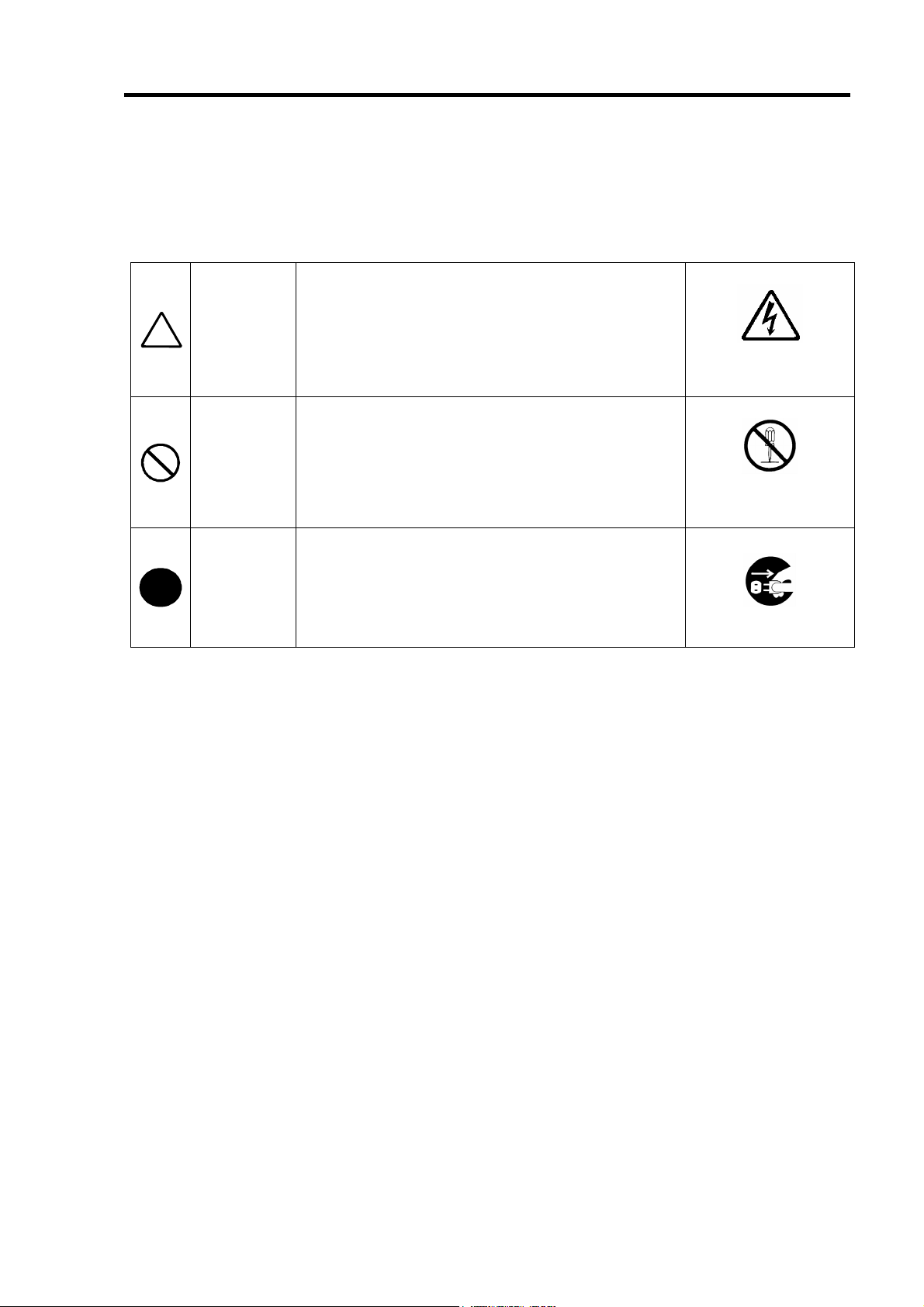
危険に対する注意・表示は次の3種類の記号を使って表しています。それぞれの記号は次
のような意味を持つものとして定義されています。
Precautions against hazards are presented with the following symbols. The individual
symbols are defined as follows:
(例) (Example)
この記号は危険が発生するおそれがあることを表し
注意の喚起
Attention
行為の禁止
Prohibited
Action
行為の強制
Mandatory
Action
ます。記号の中の絵表示は危険の内容を図案化したも
のです。
This symbol indicates the presence of a hazard.
An image in the symbol illustrates the hazard type.
この記号は行為の禁止を表します。記号の中や近くの
絵表示は、してはならない行為の内容を図案化したも
のです。
This symbol indicates prohibited actions. An image
in the symbol illustrates a particular prohibited action.
この記号は行為の強制を表します。記号の中の絵表示
は、しなければならない行為の内容を図案化したもの
です。危険を避けるためにはこの行為が必要です。
This symbol indicates mandatory actions. An image
in the symbol illustrates a mandatory action to avoid
a particular hazard.
(感電注意)
Precaution against
electric shock
(例) (Example)
(分解禁止)
Prohibition of
disassembly
(例) (Example)
(プラグを抜け)
Unplug the power cord!
iii
Page 6
iv
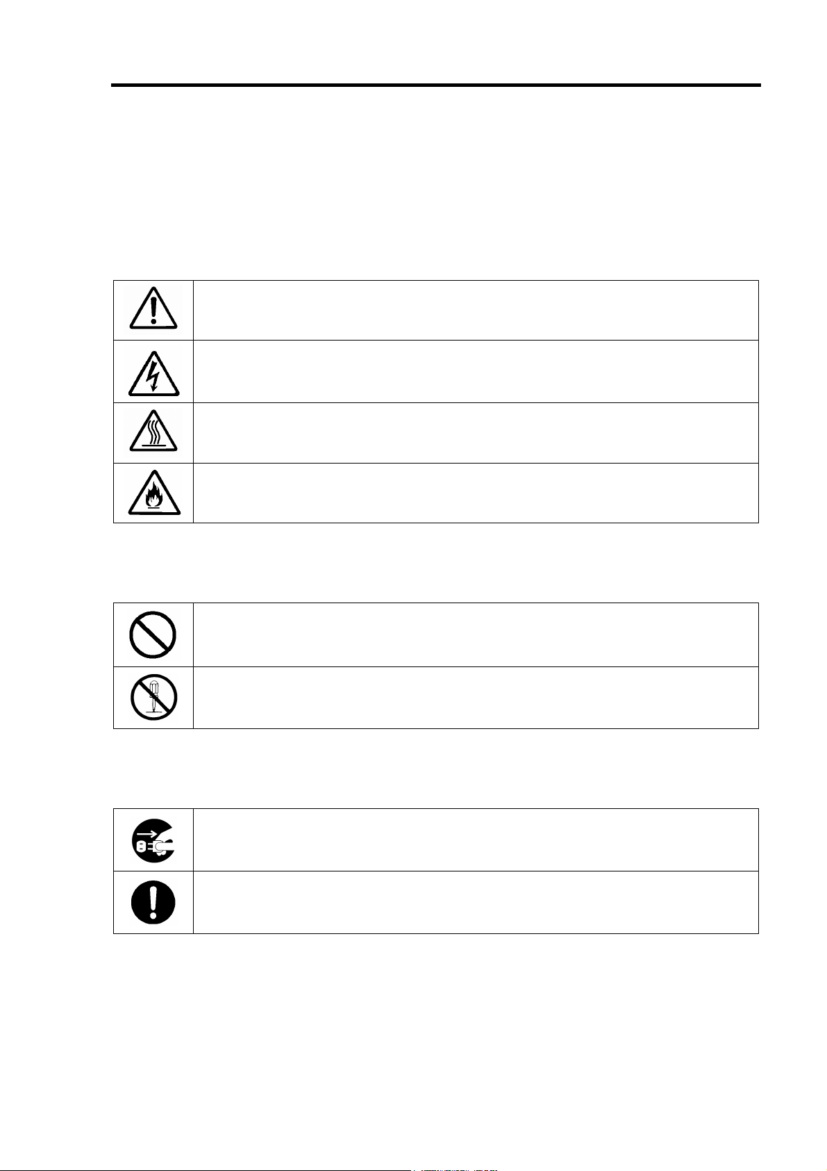
本書で使用する記号とその内容
Symbols Used in This Manual and Warning Labels
注意の喚起
Attentions
特定しない一般的な注意・警告を示します。
Indicates a general notice or warning that cannot be specifically identified.
感電のおそれがあることを示します。
Indicates that improper use may cause an electric shock.
高温による障害を負うおそれがあることを示します。
Indicates that improper use may cause personal injury.
発煙または発火のおそれがあることを示します。
Indicates that improper use may cause fumes or fire.
行為の禁止
Prohibited Actions
特定しない一般的な禁止を示します。
Indicates a general prohibited action that cannot be specifically identified.
分解・修理しないでください。感電や火災のおそれがあります。
Do not disassemble, repair, or modify the server. Otherwise, an electric shock or fire
may be caused.
行為の強制
Mandatory Action
電源コードをコンセントから抜いてください。火災や感電のおそれがあります。
Unplug the power cord of the server. Otherwise, an electric shock or fire may be
caused.
特定しない一般的な使用者の行為を指示します。説明に従った操作をしてください。
Indicates a mandatory action that cannot be specifically identified. Make sure to
follow the instruction.
Page 7
v
安全上のご注意
Safety Indications
本製品を安全にお使いいただくために、ここで説明する注意事項をよく読んでご理解して
いただき、安全にご活用ください。記号の説明については巻頭の『安全にかかわる表示に
ついて』の説明を参照してください。
This section provides notes on using your product safely. Read this section carefully to
ensure proper and safe use of the product. For symbols, see "SAFETY INDICATIONS"
provided earlier.
<全般的な注意事項>
General
人命に関わる業務や高度な信頼性を必要とする業務には使用しない
Do not use the product in life-critical applications or applications requiring
high reliability.
本製品は、医療機器、原子力設備や機器、航空宇宙機器、輸送設備や機器など人命
に関わる設備や機器、および高度な信頼性を必要とする設備や機器などへの組み込
みや制御等の使用は意図されておりません。これら設備や機器、制御システムなど
に本製品を使用され、人身事故、財産損害などが生じても、当社はいかなる責任も
負いかねます。
The product is not intended for integration with or control of facilities or equipment
that may affect human life or that require a high degree of reliability, such as
medical equipment, nuclear power facilities or instruments, aerospace instruments,
transportation facilities or instruments. NEC does not assume any liability for
accidents resulting in injury or death, or for any damages to property that may occur
as a result of using the product in such facilities, equipment, or control systems.
煙や異臭・異音がしたまま使用しない
Do not use the server if any smoke, odor, or noise is present.
万一、煙、異臭、異音などが生じた場合は、ただちに本体装置の電源をOFFにして
電源コードをACコンセントから抜いてください。その後、お買い求めの販売店また
は保守サービス会社にご連絡ください。そのまま使用すると火災の原因となります。
If smoke, odor, or noise is present, immediately turn off the server and disconnect
the power plug from the AC outlet, then contact your service representative. Using
the server in such conditions may cause a fire.
針金や金属片を差し込まない
Keep needles or metal objects away from the server.
通気孔やカートリッジ挿入口から金属片や針金などの異物を差し込まないでくださ
い。感電するおそれがあります。
Do not insert needles or metal objects into ventilation holes or cartridge slot of the
server. Doing so may cause an electric shock.
WARNING
Page 8
vi
CAUTION
装置内に水や異物を入れない
Keep water or foreign matter away from the server.
装置内に水などの液体、ピンやクリップなどの異物を入れないでください。火災や
感電、故障の原因となります。もし入ってしまったときは、すぐに本体装置の電源
をOFFにして電源コードをACコンセントから抜いてください。分解しないで販売店
または保守サービス会社に連絡してください。
Do not let any form of liquid (water etc.) or foreign matter (e.g., pins or paper clips)
enter the server. Failure to follow this warning may cause an electric shock, a fire, or
a failure of the server. When such things accidentally enter the server, immediately
turn off the power and disconnect the power plug from the AC outlet. Do not
disassemble the server. Contact your service representative.
Page 9
<電源・電源コードに関する注意事項>
Power Supply and Power Cord Use
vii
電源がONのまま取り付け・取り外しをしない
Disconnect the power cord(s) before installing or removing the product
in/from the server.
本体装置への取り付け・取り外しの際や、周辺機器との接続の際は必ず主電源に接
続している電源コードをACコンセントから抜いてください。電源コードがACコンセ
ントに接続されたまま取り付け・取り外しや接続をすると感電するおそれがありま
す。
Make sure to power off the server and disconnect the power cord(s) from a power
outlet before installing/removing the product in/from the server, or connecting with
the peripheral devices. All voltage is removed only when the power cords are
unplugged.
破損したケーブルを使用しない
Do not use any damaged cable.
ケーブルを接続する前にコネクタが破損していたり、コネクタピンが曲がっていた
り、汚れたりしていないことを確認してください。破損や曲がっているコネクタお
よび汚れたコネクタを使用するとショートにより火災を引き起こすおそれがありま
す。
Make sure the cable condition before connection. Using the damaged connector,
bent connector pin, or dirty connector may cause a fire due to short-circuit.
ぬれた手で電源コードをもたない
Do not hold the power plug with a wet hand.
本製品の取り付け・取り外しの場合は、ぬれた手で本体装置の電源コードの抜き差
しをしないでください。感電するおそれがあります。
Do not disconnect/connect the plug while your hands are wet. Failure to follow this
warning may cause an electric shock.
電源コードのケーブル部を持って引き抜かない
Do not pull the cable when disconnecting the power cord.
本体装置の電源コードの抜き差しは、ケーブル部を持って引っ張らないでください。
ケーブルが傷み、感電や火災の原因となります。
When disconnecting the power cord from the server, hold the plug and pull it straight
out. Pulling the cord out by the cable portion could damage the cable to result in an
electrical shock hazard or a fire.
CAUTION
Page 10
viii
<設置・移動・保管・接続に関する注意事項>
Installation, Relocation, Storage, and Connection
CAUTION
プラグを差し込んだままインタフェースケーブルの取り付けや取り外しをしない
Do not connect any interface cable with the power cord of the server plugged
to a power source.
インタフェースケーブルの取り付け/取り外しは本体装置の電源コードをコンセン
トから抜いて行ってください。たとえ電源をOFFにしても電源コードを接続したま
まケーブルやコネクタに触ると感電したり、ショートによる火災を起こしたりする
ことがあります。
Make sure to power off the server and unplug the power cord from a power outlet
before connecting/disconnecting any interface cable to/from the server. If the
server is off-powered but its power cord is plugged to a power source, touching a
cable or connector may cause an electric shock or a fire resulted from a short
circuit.
指定以外のインタフェースケーブルを使用しない
Do not use any unauthorized interface cable.
インタフェースケーブルは、NECが指定するものを使用し、接続する装置やコネク
タを確認した上で接続してください。指定以外のケーブルを使用したり、接続先を
誤ったりすると、ショートにより火災を起こすことがあります。
また、インタフェースケーブルの取り扱いや接続について次の注意をお守りくださ
い。
ケーブルを踏まない。
ケーブルの上にものを載せない。
ケーブルの接続がゆるんだまま使用しない。
破損したケーブルを使用しない。
破損したケーブルコネクタを使用しない。
ネジ止めなどのロックを確実に行ってください。
Use only interface cables authorized by NEC and locate a proper device and
connector before connecting a cable. Using an unauthorized cable or connecting a
cable to an improper destination may cause a short circuit, resulting in a fire.
Also, observe the following notes on using and connecting an interface cable.
Do not step on the cable.
Do not place any object on the cable.
Do not use the server with loose cable connections.
Do not use any damaged cable connector.
Make sure the cable is securely locked with screw.
Page 11
ix
腐食性ガスの存在する環境で使用または保管しない
Do not use or store the product in the place where corrosive gases exist.
腐食性ガス(二酸化硫黄、硫化水素、二酸化窒素、塩素、アンモニア、オゾンなど)
の存在する環境に設置し、使用しないでください。
また、ほこりや空気中に腐食を促進する成分(塩化ナトリウムや硫黄など)や導電
性の金属などが含まれている環境へも設置しないでください。装置内部のプリント
板が腐食し、故障および発煙・発火の原因となるおそれがあります。もしご使用の
環境で上記の疑いがある場合は、販売店または保守サービス会社にご相談ください。
Make sure not to locate or use the server in the place where corrosive gases (sulfur
dioxide, hydrogen sulfide, nitrogen dioxide, chlorine, ammonia, ozone, etc) exist.
Also, do not install it in the environment where the air (or dust) includes components
accelerating corrosion (ex. sulfur, sodium chloride) or conductive metals. There is a
risk of a fire due to corrosion and shorts of an internal printed board.
Consult with your service representative for the location appropriate to the server.
高温注意
Avoid installation in extreme temperature conditions.
本体装置の電源をOFFにした直後は、内蔵型のハードディスクドライブなどをはじ
め装置内の部品が高温になっています。十分に冷めたことを確認してから取り付け/
取り外しを行ってください。
Immediately after the server is powered off, its internal components such as hard
disk drives are very hot. Leave the server until its internal components fully cool
down before installing/removing any component.
CAUTION
Page 12
x
<お手入れに関する注意事項>
Cleaning and Working wit
h the Product
自分で分解・修理・改造はしない
Do not disassemble, repair, or alter the server.
本製品の分解や、修理・改造は絶対にしないでください。装置が正常に動作しなく
なるばかりでなく、感電や火災の危険があります。
Never attempt to disassemble, repair, or alter the product on any occasion. Failure
to follow this instruction may cause an electric shock or fire as well as malfunctions
of the product.
プラグを差し込んだまま取り扱わない
Disconnect the power plug before accessing inside the server.
お手入れは、本体装置の電源をOFFにして、電源コードをACコンセントから抜いて
ください。たとえ電源をOFFにしても、電源コードを接続したまま装置内の部品に
触ると感電するおそれがあります。
Make sure to power off the server and disconnect the power plug from a AC outlet
before accessing inside the server. Touching any internal device of the server with
its power cord connected to a power source may cause an electric shock even if the
server is off-powered.
WARNING
中途半端に取り付けない
Make sure to complete installation.
DCケーブルやインタフェースケーブルは確実に取り付けてください。中途半端に取
り付けると接触不良を起こし、発煙や発火の原因となるおそれがあります。
Always connect the DC cable and/or interface cable firmly. An incompletely
connected cable may cause a contact failure, resulting in smoking or fire.
CAUTION
Page 13
<運用中の注意事項>
During Operation
xi
CAUTION
雷がなったら触らない
Avoid contact with the server during thunderstorms.
雷が鳴りだしたら、本製品内蔵の本体装置には、触れないでください。感電するお
それがあります。
Disconnect the power plug from the outlet when a thunderstorm is approaching.
If it starts thundering before you disconnect the power plug, do not touch any part of
the server containing the product. Failure to follow this warning may cause an
electric shock.
ペットを近づけない
Keep animals away from the server.
本製品が内蔵された本体装置にペットなどの生き物を近づけないでください。排泄
物や体毛が装置内部に入って火災や感電の原因となります。
Keep animals away from the server containing the product.
Pet's discharges or fur may enter the server and cause a fire or electric shock.
近くで携帯電話やPHSを使用しない
Do not use a cellular phone or a pager around the server.
本製品が内蔵された本体装置のそばでは、携帯電話やPHS、ポケットベルの電源を
OFFにしてください。電波による誤動作の原因となります。
Turn off the cellular phone or pager near the server containing the product. Radio
interference may cause malfunctions of the server.
Page 14
xii
使用上のご注意 ~装置を正しく動作させるために~
本製品を使用するときに注意していただきたいことを次に示します。これらの注意を無視
して、本製品を使用した場合、資産(データやその他の装置)が破壊されるおそれがあります
ので必ずお守りください。
本製品は Express5800 シリーズに Serial-ATA(SATA)機器を接続するためのディ
スクアレイコントローラです。他の目的では使用しないでください。
本製品は大変デリケートな電子装置です。本製品を取り扱う前に、本体装置の金
属フレーム部分などに触れて身体の静電気を逃がしてください。本製品の取り扱
いは端の部分を持ち、表面の部品やコネクタと接続する部分には触れないように
してください。また、本製品を落としたり、ぶつけたりしないでください。
本製品には、同一規格のハードディスクドライブ(以降「HDD」と呼ぶ)を接続
してください。
本製品に接続可能な本体装置、増設用 HDD ケージ、HDD については、お買い求
めの販売店にお問い合わせください。
本製品は、他の PCI ボード(ディスクアレイコントローラ、ミラーリングボード、
SCSI コントローラ等)の混在使用を制限している場合があります。本製品を他の
PCI ボードと混在してご使用になる場合は、混在が可能かどうかお買い求めの販
売店にご確認ください。
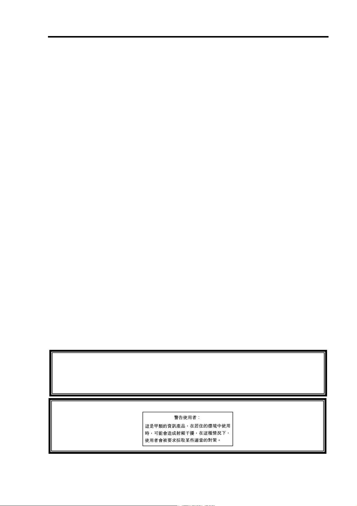
電波障害自主規制について
この装置は、情報処理装置等電波障害自主規制協議会(VCCI)の基準に基づくクラス A 情報
技術装置です。この装置を家庭環境で使用すると電波妨害を引き起こすことがあります。この
場合には使用者が適切な対策を講ずるよう要求されることがあります。
BSMI Statement
Page 15
xiii
本書について
This Manual
本書は、Windows などのオペレーティングシステムやキーボード、マウスといった一般的
な入出力装置などの基本的な取り扱いについて十分な知識を持ったユーザを対象として記
載されています。
The guide is intended for persons who are familiar with operating systems including
Windows and fundamental operations of general-purpose I/O devices including the
keyboard and mouse.
<本書の記号について>
Text Conventions
本書の中には安全に関わる注意記号の他に次の3種類の記号を使用しています。それぞれ
の記号は次のような意味をもつものとして定義されています。
The following conventions are used throughout this User's Guide. For safety symbols, see
"SAFETY INDICATIONS" provided earlier.
装置を取り扱う上で、守らなければいけないことや、特に注意すべき
点を示します。
Notice
Check
Tips
Items to be observed or points to be noted when operating the
product.
装置を取り扱う上で、確認をしておく必要がある点を示します。
Items to be checked when operating the product
知っておくと役に立つ情報や便利なことを示します。
Information useful or convenient for you
梱包箱の中身について
In the Package
梱包箱の中には本製品以外に色々な添付品が同梱されています。本製品に添付の構成品表
を参照し、全ての添付品が揃っていることを確認してください。万一、足りないものや損
傷しているものがあった場合には、本製品をご購入された販売店にご連絡ください。
The carton contains various accessories, as well as the product itself. See the packing list
to make sure that you have everything and that individual components are not damaged. If
you find any component missing or damaged, contact your sales agent.
Page 16
xiv
第三者への譲渡について
Transfer to Third Party
本製品を第三者に譲渡(または売却)する時には、必ず本書を含む全ての添付品をあわせ
て譲渡(または売却)してください。
Make sure to provide this manual along with the product to a third party.
HDD内のデータについて
譲渡する装置内に搭載されているHDDに保存されている大切なデータ(例えば顧客
情報や企業の経理情報など)が第三者へ漏洩することの無いようにお客様の責任に
おいて確実に処分してください。
WindowsやLinuxなどのオペレーティングシステムの「ゴミ箱を空にする」操作や
オペレーティングシステムの「フォーマット」コマンドでは見た目は消去されたよ
Notice
ソフトウェアに関しては、譲渡した側は一切の複製物を所有しないでください。また、イ
ンストールした装置から削除した後、譲渡してください。
うに見えますが、実際のデータはHDDに書き込まれたままの状態にあります。完全
に消去されていないデータは、特殊なソフトウェアにより復元され、予期せぬ用途
に転用されるおそれがあります。
このようなトラブルを回避するために市販の消去用ソフトウェア(有償)またはサー
ビス(有償)を利用し、確実にデータを処分することを強くお勧めします。データの
消去についての詳細は、お買い求めの販売店または保守サービス会社にお問い合わ
せください。
なお、データの処分をしないまま、譲渡(または売却)し、大切なデータが漏洩さ
れた場合、その責任は負いかねます。
About data on the hard disk
Be sure to take appropriate measures not to leak important data (e.g., customers'
information or companies' management information) on the removed hard disk to
any third parties.
Data seems to be erased when you empty "Recycle Bin" of Windows or execute
the "format" command of the operating system. However, the actual data remains
written on the hard disk. Data not erased completely may be restored by special
software and used for unexpected purposes.
It is strongly recommended that the software or service (both available at stores)
for data erasure should be used in order to avoid the trouble explained above. For
details on data erasure, ask your sales representative.
NEC assumes no liability for data leakage if the product is transferred to third party
without erasing the data.
To transfer or sell any software application that comes with the product to a third party, the
following requirements must be satisfied:
All provided software applications must be transferred and no backup copies must be
retained.
Software applications must be uninstalled before transferring the product.
Page 17
xv
廃棄について
Disposal
本製品の廃棄については、各自治体の廃棄ルールに従って分別廃棄して下さい。詳しくは、
各自治体にお問い合わせ下さい。
Dispose of the product according to all national laws and regulations.
HDDやバックアップデータカートリッジ、フロッピーディスク、その他書
き込み可能なメディア(CD-R/CD-RWなど)に保存されているデー
タは、第三者によって復元や再生、再利用されないようお客様の責任にお
Notice
いて確実に処分してから廃棄してください。個人のプライバシーや企業の
機密情報を保護するために十分な配慮が必要です。
It is the user's responsibility to completely erase or modify all the data
stored in storage device such as hard disk, backup data cartridge, floppy
disk, or any other media (CD-R/CD-RW) so that the data cannot be
restored.
データの保管について
Data Backup
オペレータの操作ミス、衝撃や温度変化等による装置の故障によってデータが失われる可
能性があります。万一に備えて、HDD に保存されている大切なデータは、定期的にバック
アップを行ってください。
The device failure due to shock or thermal changes, as well as operator's misconduct, may
cause loss of data. To avoid loss of data, NEC recommends that you should make a
back-up copy of your valuable data on a regular basis.
輸送について
Transportation
本製品を輸送する際は、『第1章 概要』を参考に本体装置から本製品を取り出し、本製品
とすべての添付品を購入時の梱包箱に入れてください。
To transport the product, remove the product from the server and put it in the shipping
carton along with accessories according to Chapter 1.
保守用部品について
Maintenance Parts
本製品の保守用部品の保有期間は、製造打ち切り後5年です。
The holding period of maintenance parts of the BBU is five years from the truncation of
manufacturing.
Page 18
xvi
本書で使用する略称
Abbreviations
正 式 名 称
Formal title
N8103-89 ディスクアレイコントローラ(SATA)
ユーザーズガイド
N8103-89 Disk Array Controller (SATA) User’s Guide
N8103-89 ディスクアレイコントローラ(SATA)
N8103-89 Disk Array Controller (SATA)
N8103-93 増設バッテリ(SATA)
N8103-93 Additional DAC Battery (SATA)
N8154-01 増設用 HDD ケージ(S-ATA)
N8154-01F S-ATA HDD Cage
N8154-09 増設用 HDD ケージ(SATA2)
N8154-09F SATA2 HDD Cage
Web-based Promise Array Manager WebPAM
オペレーションシステム
Operation System
ハードディスクドライブ
Hard disk drive
略 称
Abbreviation
本書
this manual
本製品またはディスクアレイコント
ローラ
disk array controller or card
増設バッテリ
additional battery
増設用 HDD ケージ
additional HDD cage
※ 区別する必要がある場合は正式名
称で記載する
* Specified by their formal titles if
they should be distinguished.
OS
HDD
Page 19

目 次
まえがき Preface ......................................................................................................................... i
使用上のご注意 ~必ずお読みください~
NOTES ON USE - Always read the Notes -.................................................................... ii
本書で使用する記号とその内容 Symbols Used in This Manual and Warning Labels ................ iv
安全上のご注意 Safety Indications.............................................................................................. v
使用上のご注意 ~装置を正しく動作させるために~..............................................................xii
本書について This Manual ........................................................................................................xiii
梱包箱の中身について In the Package .....................................................................................xiii
第三者への譲渡について Transfer to Third Party ......................................................................xiv
廃棄について Disposal.............................................................................................................. xv
データの保管について Data Backup......................................................................................... xv
輸送について Transportation..................................................................................................... xv
保守用部品について Maintenance Parts ................................................................................... xv
本書で使用する略称 Abbreviations ...........................................................................................xvi
xvii
第 1 章 概要.........................................................................................................................1
1.運用上のご注意~必ずお守りください~...................................................................................... 1
1-1. WebPAM のインストールについて...................................................................................... 1
1-2.メディアパトロール/シンクロナイズによる予防保守 ........................................................... 2
2.仕様............................................................................................................................................... 3
3.本製品の特徴................................................................................................................................. 4
4.各部の名称と機能 ......................................................................................................................... 5
5.ハードウェアのセットアップ........................................................................................................ 7
5-1.セットアップの準備 .............................................................................................................. 8
5-2.ブラケットの選択・取り付け ................................................................................................ 9
5-3.本製品の取り付け................................................................................................................ 10
5-4. LED ケーブルと SATA ケーブルの接続............................................................................. 11
5-5.増設用 HDD ケージの取り付け........................................................................................... 12
5-6. I2C ケーブルの接続 ........................................................................................................... 12
5-7.ケーブルのフォーミング ..................................................................................................... 13
第 2 章 RAID について ..................................................................................................... 15
1. RAID の概要............................................................................................................................... 15
1-1. RAID(Redundant Array of Inexpensive Disks)とは............................................................. 15
1-2. RAID レベルについて ......................................................................................................... 15
1-3.ロジカルドライブ(Logical Drive)......................................................................................... 16
1-4.パリティ(Parity)................................................................................................................... 16
1-5.ホットスワップ ................................................................................................................... 16
1-6.ホットスペアディスク(Hot Spare)....................................................................................... 17
2. RAID レベル .............................................................................................................................. 18
2-1. RAID レベルの特徴............................................................................................................. 18
2-2.「RAID0」について............................................................................................................. 18
2-3.「RAID1」について............................................................................................................. 19
2-4.「RAID5」について............................................................................................................. 19
2-5.「RAID10」について........................................................................................................... 20
Page 20

xviii
第 3 章 本製品の機能について .......................................................................................... 21
1.リビルド...................................................................................................................................... 21
1-1.マニュアルリビルド(手動リビルド)..................................................................................... 21
1-2.オートリビルド(自動リビルド)............................................................................................ 21
2.メディアパトロール.................................................................................................................... 23
3.シンクロナイズ ........................................................................................................................... 24
4.エクスパンション ....................................................................................................................... 25
第 4 章 ランプ表示について.............................................................................................. 27
1.本体装置のランプ表示 ................................................................................................................ 27
2.トレーのディスクランプ表示...................................................................................................... 28
第 5 章 ロジカルドライブの作成....................................................................................... 29
1.FastBuild Utility を使用する前に................................................................................................. 29
1-1.サポート機能 ....................................................................................................................... 29
1-2.ロジカルドライブ作成時の注意事項 ................................................................................... 30
2. FastBuild Utility の起動とメニュー ............................................................................................ 33
2-1. FastBuild Utility の起動 ...................................................................................................... 33
2-2. Main Menu.......................................................................................................................... 34
2-3. View Drive Assignments .....................................................................................................35
2-4. Define LD............................................................................................................................37
2-5. Delete LD............................................................................................................................38
2-6. Controller Configuration...................................................................................................... 39
2-7. FastBuild Utility の終了 ...................................................................................................... 40
3.ロジカルドライブの作成............................................................................................................. 41
3-1.ロジカルドライブの作成作業フロー ................................................................................... 41
3-2. FastBuild Utility の設定項目 ............................................................................................... 42
3-3.ロジカルドライブの作成方法 .............................................................................................. 43
第 6 章 運用・保守 ............................................................................................................ 48
1.保守サービス............................................................................................................................... 48
2.予防保守...................................................................................................................................... 48
2-1.データのバックアップ......................................................................................................... 48
2-2.メディアパトロール/シンクロナイズによる予防保守 ......................................................... 48
3.保守機能について ....................................................................................................................... 49
3-1. Configuration on Disk(COD)機能 ........................................................................................ 49
3-2.リビルド機能 ....................................................................................................................... 49
3-3.クリティカルブート機能 ..................................................................................................... 49
4.本製品の交換............................................................................................................................... 50
5.トラブルシューティング............................................................................................................. 51
Page 21

第 1 章 概要
本製品を初めてお使いになる場合は、この章からお読みください。
ここでは、本製品の運用上必ずお守りしていただきたい事項、ならびに、本製品の特徴と
ハードウェアのセットアップについて説明します。
1.運用上のご注意~必ずお守りください~
本製品を安全に運用していただくため、以下の注意事項をお守りください。
1-1. WebPAM のインストールについて
本製品をオペレーティングシステム(以降「OS」と呼ぶ)上から管理することができる管理
ユーティリティ Web-based Promise Array Manager(以降「WebPAM」と呼ぶ)を必ずイン
ストールしてください。WebPAM をインストールすることにより、
アレイシステム上発生したイベントや異常がイベントログに登録され、システム
の障害解決や診断に有効活用できます。
ESMPRO を使って WebPAM のイベント情報を監視することが可能です。
マニュアルリビルド/メディアパトロール/シンクロナイズの実行やスケジュール
運転が可能になります。
WebPAM のインストール方法は、本製品添付の CD-ROM「S-ATA Array Management
Software」内のオンラインマニュアル「N8103-89 ディスクアレイコントローラ(SATA)ソ
フトウェアユーザーズガイド」をご覧ください。
Page 22
2
1-2.メディアパトロール/シンクロナイズによる予防保守
ハードディスクドライブ(以降「HDD」と 呼 ぶ )の後発不良に対する予防保守として、メディ
アパトロールやシンクロナイズを定期的に実施することをお勧めします。これらの機能に
より、HDD の後発不良を早期に発見し修復することができます。どちらの機能も、
WebPAM のスケジュール機能により定期的に実施することができます。
メディアパトロールとシンクロナイズの詳しい機能については、『第 3 章本製品の機能に
ついて』をご覧ください。
スケジュールの間隔は週に 1 度実施されることを推奨していますが、お客さまの運用状況
に合わせ、少なくとも月に 1 度は実施されることをお勧めしています。
メディアパトロールやシンクロナイズを実施するためには、WebPAM のイ
ンストールが必要になります。
Page 23
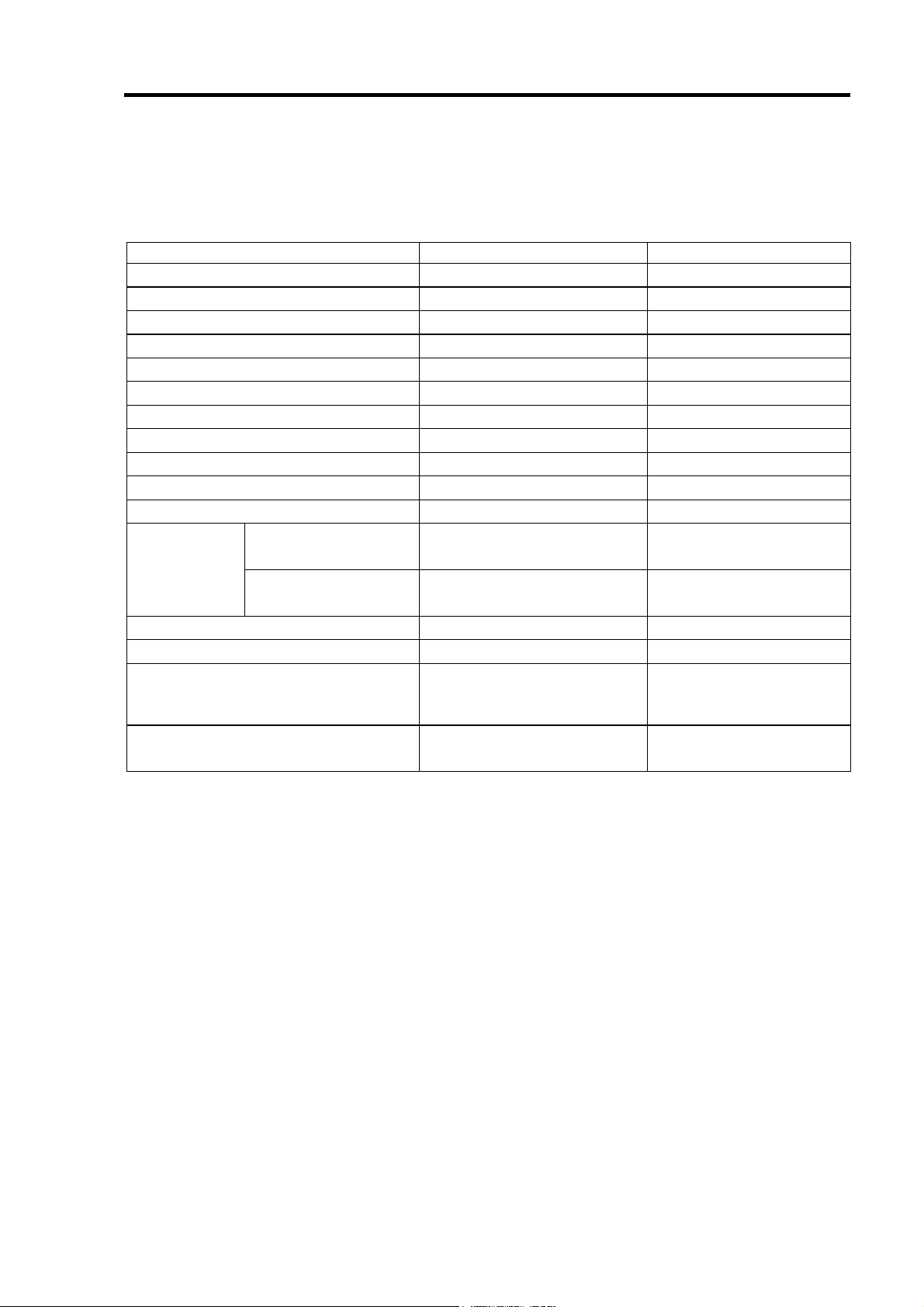
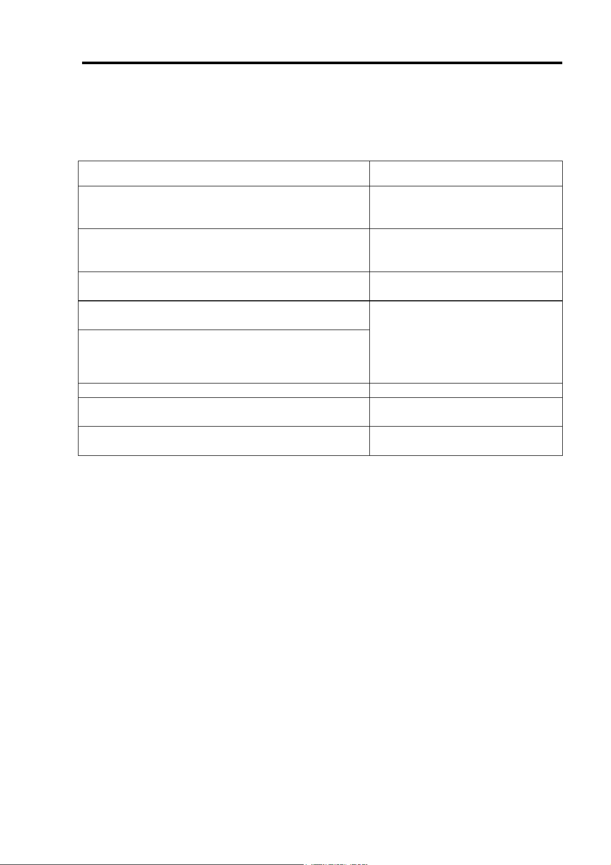
2.仕様
項 目 仕 様 備 考
SATA コネクタ数 内部 4 チャネル
キャッシュ容量
PCI バス PCI2.3 準拠
PCI コネクタ ユニバーサル/32Bit
最大 PCI バス転送レート
デバイスインターフェース Serial ATA Generation1 対応
最大データ転送レート
RAID レベル
本体装置への最大搭載数 1枚
最大 HDD 接続台数 4台 1チャネルに HDD1 台接続
最大ロジカルドライブ数
外形寸法
質量 約 0.09kg
動作電圧
消費電力(MAX)
動作環境 温度 10°C~35°C
フルハイト PCI
ブラケット使用時
ロープロファイル PCI
ブラケット使用時
64MB
266MB/sec
150MB/sec
0, 1, 5, 10
8
121(幅)x180(長さ)x22(高)mm
81(幅)x180(長さ)x22(高)mm
5V
5.3W 3.3V/1.044A
湿度 20%~80%
SATA Signal: 7pin
66MHz
3.3V/0.458A(SDRAM)
1.8V/0.174A
結露しないこと
3
Page 24
4
3.本製品の特徴
本製品は、Serial-ATA Generation1 対応の I/F コネクタが 4 チャネル搭載されています。
データ転送速度は、1 チャネルあたり最大 150MB/秒であり、低コスト、高パフォーマン
スを実現しています。
さらに、N8103-93 増設バッテリ(SATA)(以降「増設バッテリ」と呼ぶ)と接続することで、
アクセス性能がより向上する「Write Back」モードでの運用が可能になります。また、増
設用 HDD ケージと接続することでホットスワップ機能も実現します。
本製品の特徴
最大 150MB/秒のデータ転送
64MB SDRAM メモリを搭載
1 ボードあたり最大 4 台の SATA HDD を接続可能(1 チャネル当たり 1 台)
RAID レベル 0, 1, 5, 10 をサポート
増設バッテリを接続することにより、「Write Back」モードでの運用が可能
WebPAM をインストールすることにより ESMPRO を使った通報監視が可能
障害発生ドライブの自動検出
システムを停止せずに故障 HDD の交換(ホットスワップ)が可能(専用の増設用
HDD ケージ接続時)
サウンドを使用した警告が可能
ロープロファイル対応
本製品は、PCI ホットプラグ機能をサポートしておりません。
本製品と接続できる増設用HDD ケージは次の2つです。
N8154-01 増設用HDD ケージ(S-ATA)
N8154-09 増設用HDD ケージ(SATA2)
Page 25
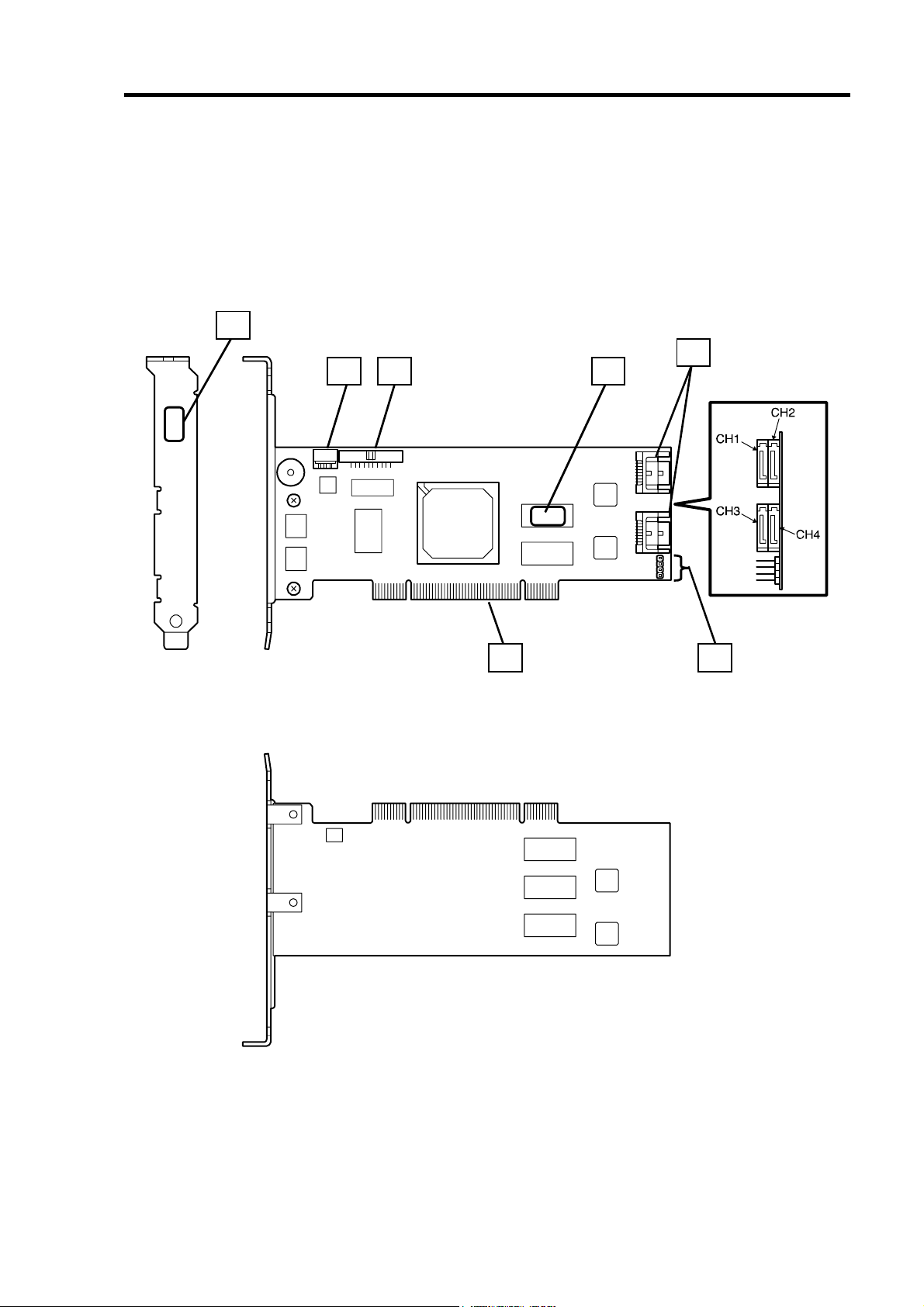
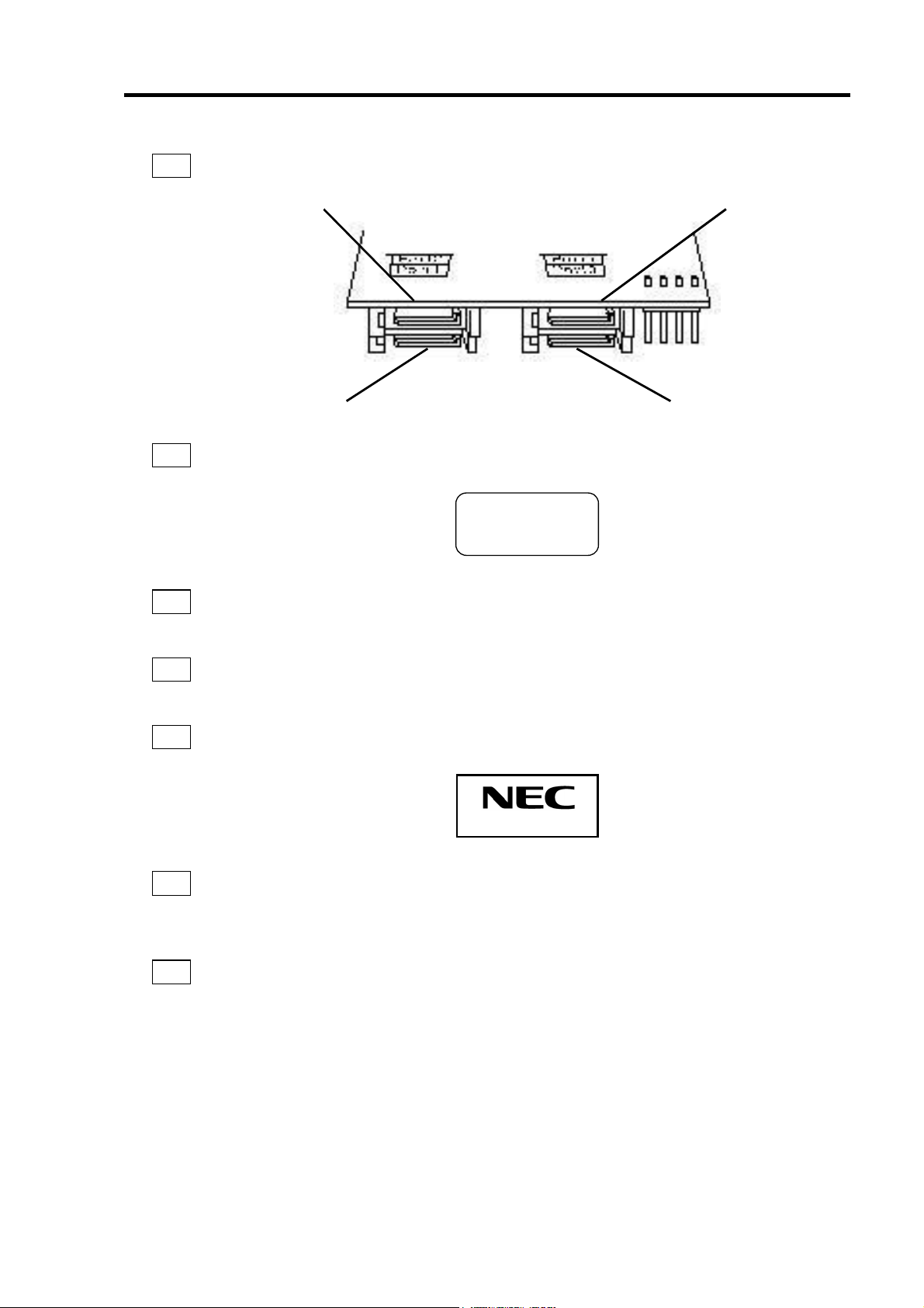
4.各部の名称と機能
本製品の各部の名称を以下に説明いたします。
(本製品表面)
5
34
5
1
2
(本製品裏面)
7 6
Page 26
6
1
チャネル 1~4(Port 1~4)
SATA デバイス機器を接続するためのコネクタです。
チャネル
2
チャネル
4
2
HW ラベル
本製品の管理レビジョンを表示しているラベルです。
3
増設バッテリ用コネクタ
N8103-93 増設バッテリ(SATA)を接続するためのコネクタです。
4
I2C コネクタ
I2C ケーブルを接続するコネクタです。
5
N コードラベル
本製品のNコードを表示しています。
チャネル
1
チャネル
3
REV
XXX
N8103-89
6
7
HDD LED コネクタ
本体装置の DISK ACCESS ランプを点灯させるために、本体装置のマザーボードと接続
します。
PCI コネクタ
本体装置の PCI スロットに接続するコネクタです。
Page 27
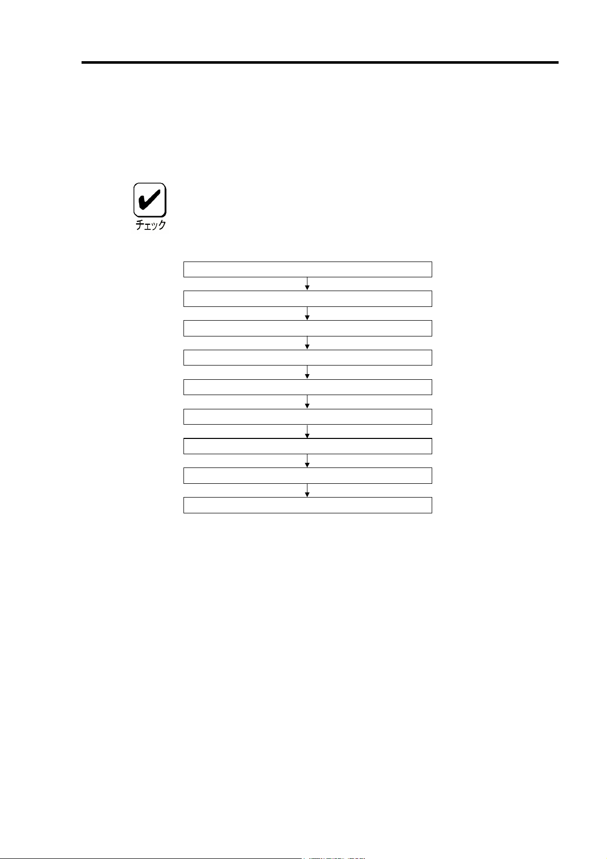
5.ハードウェアのセットアップ
次の手順に従って、本製品を本体装置に取り付けてください。
作業の前に本体装置のユーザーズガイドも必ずご覧になってください。作業
フローは本体装置や装置構成、増設用HDD ケージの有無によって異なりま
す。作業開始前に本体装置の種類および装置構成を確認して正しいフローを
実施してください。
7
本製品の取り付け(増設バッテリ接続)
LED ケーブルと SATA ケーブルの接続
増設用 HDD ケージの取り付け(*)
SATA ケーブルのフォーミング
セットアップ開始
セットアップの準備
ブラケットの選択・取り付け
I2C ケーブルの接続(*)
セットアップ終了
(*)増設用 HDD ケージを使用しない場合は、作業はありません。
Page 28
8
5-1.セットアップの準備
セットアップを行う前に、以下の注意事項をご覧ください。
本製品は、本体装置1台に対して1枚のみ実装可能です。複数枚の実装は
できません。
PCI スロットには、本体装置により実装制限がある場合があります。取
り付ける前に本体装置のユーザーズガイドを確認してください。
本製品に接続するHDD は、同一規格のHDD を使用してください。本製
品に接続可能なHDD については、お買い求めの販売店にご確認くださ
い。
本製品は、他のPCI ボード(ディスクアレイコントローラ、ミラーリング
ボード、SCSI コントローラ等)の混在使用を制限している場合がありま
す。本製品を他のPCI ボードと混在してご使用になる場合は、混在が可
能かどうかお買い求めの販売店にご確認ください。
1. すべてのアプリケーションを終了し、OS のシャットダウン処理を行います。
2. POWER スイッチを押して本体装置の電源をOFFにします。
3. 本体装置の電源ユニットに接続している全ての電源コードをコンセントから抜き
ます。
4. 本体装置のユーザーズガイドの手順に従い、本体装置のサイドカバー等を外しま
す。
本体装置サイドカバー等の取り付け/取り外し手順は、本体装置のユーザー
ズガイドをご覧ください。
Page 29
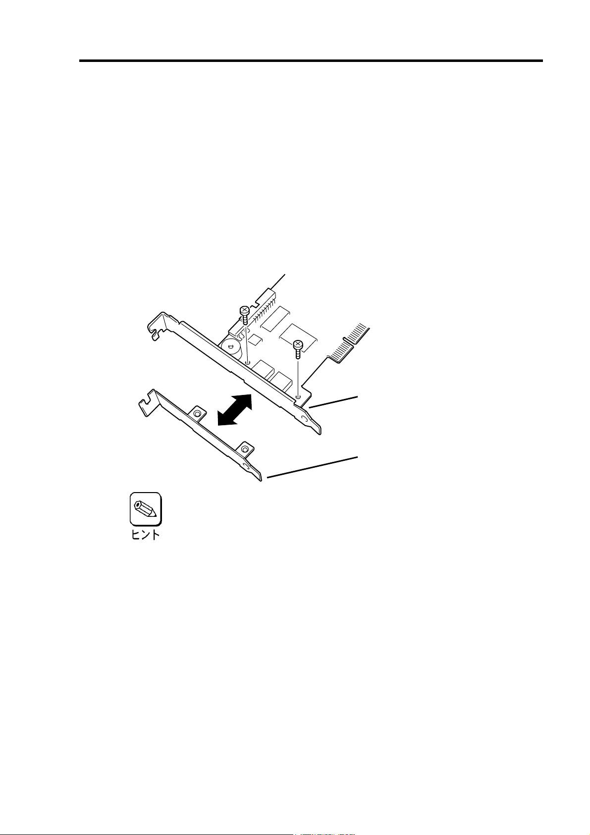
5-2.ブラケットの選択・取り付け
本製品はフルハイト PCI ブラケットが取り付けられています。ロープロファイルに対応し
た PCI スロットに本製品を取り付ける場合は、添付のロープロファイル PCI ブラケットに
交換する必要があります。
1. フルハイト PCI ブラケットと本製品を固定しているネジ(2 本)を取り外します
2. フルハイト PCI ブラケットを取り外します。
3. ロープロファイル PCI ブラケットを取り付けます。
4. ロープロファイル PCI ブラケットを手順1 で取り外したネジ(2 本)で固定します。
9
フルハイト
ロープロファイル
ブラケット
PCI
ブラケット
PCI
ロープロファイルPCIブラケットからフルハイトPCIブラケットに取り替え
る時も同じ手順です。
Page 30
10
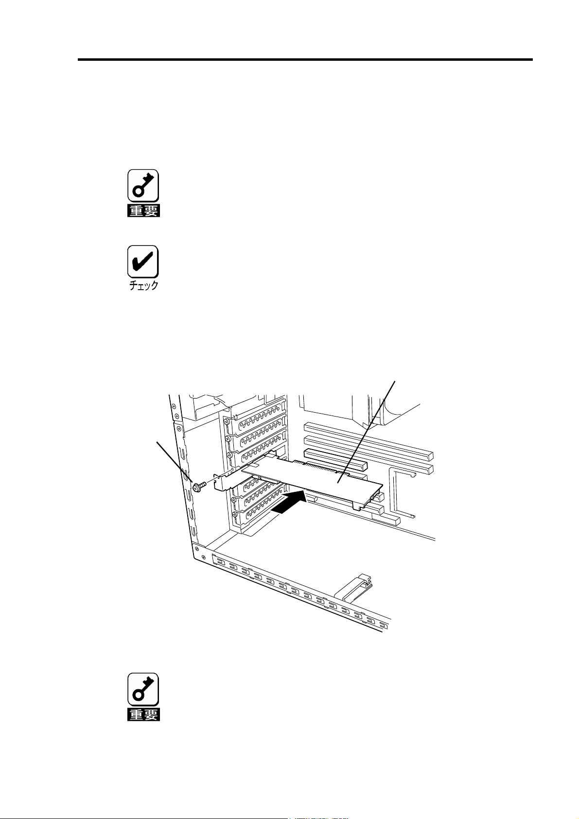
5-3.本製品の取り付け
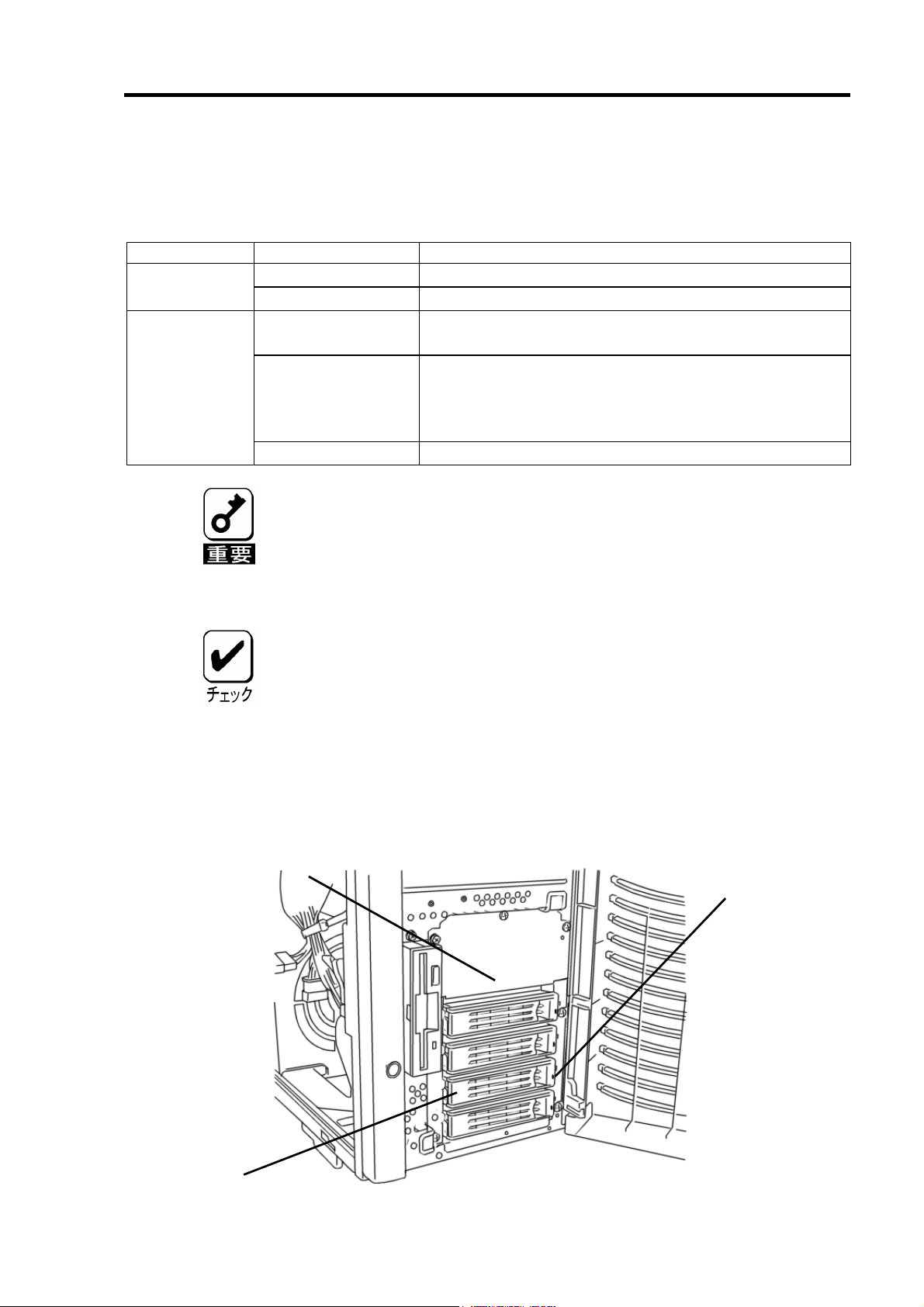
1. 本製品を取り付ける PCI スロットの位置を確認し、対応する増設スロットカバー
を取り外します。
取り外した増設スロットカバーは大切に保管してください。外したネジ
は、本製品の取り付けに使用しますので、なくさないでください。
本製品は、PCI ホットプラグ機能には対応していません。本製品を抜き
2. 本製品を PCI スロットにしっかりと差し込み、固定します。ネジで固定する場合
は、増設スロットカバーを取り外した時のネジを使用して固定します。
差しする場合は、必ず本体装置の電源をOFF にして、電源コードをコン
セントから抜いてください。
PCI スロットには、本体装置により実装制限がある場合があります。取り
付ける前に本体装置のユーザーズガイドをご覧ください。
本製品
(ディスクアレイコントローラ)
ネジ
3. 増設バッテリを接続する場合も、同様の手順で取り付けてください。
本製品がPCI スロットにうまく取り付けられない場合は、一旦本製品を
取り外して、再度取り付けなおしてください。過度の力を加えると破損
するおそれがありますので注意してください。
増設バッテリの詳しい取り付け方法については、「N8103-93 増設バッ
テリ(SATA)ユーザーズガイド」をご覧ください。
Page 31
11
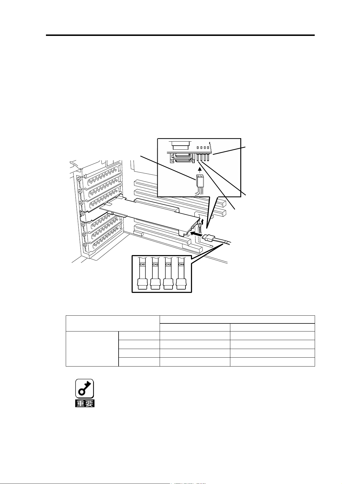
5-4. LED ケーブルと SATA ケーブルの接続
本体装置添付の LED ケーブルを HDD LED コネクタに接続します。以下の図および接続
表を参照して接続してください。マザーボードへの接続については本体装置のユーザーズ
ガイドをご覧ください。LED ケーブルが接続しづらい場合は、一旦本製品を PCI スロット
から抜いて接続してください。
続けて、SATA ケーブルを本製品の SATA コネクタに接続します。本製品のチャネル番号
(Port 番号)と同じチャネル番号の SATA ケーブルを接続します。
LED ケーブル接続表
LED ケーブル
SATA
ケーブル
Port4
Port3
1 2 3 4
HDD LED コネクタ
黒色のケーブルを接続
赤色のケーブルを接続
(
ケーブルが1本ケー
LED
ブルの場合は使用しない)
HDD LED コネク
タ
1 ピン 赤色ケーブル接続 使用しません
2 ピン 黒色ケーブル接続 黒色ケーブル接続
LED ケーブル(本体装置添付)
2 本ケーブルの場合 1本ケーブルの場合
3 ピン 使用しません 使用しません
4 ピン 使用しません 使用しません
本体装置によっては、LED ケーブルのケーブルが2本の場合と1本の場合
があります。
LED ケーブルのマザーボードへの接続については、本体装置のユーザー
ズガイドをご覧ください。
N8154-09 増設用HDD ケージ(SATA2)を使用する場合は、増設用HDD
ケージに添付されているSATA ケーブルを接続してください。詳しい接
続方法については、増設用HDD ケージ添付のユーザーズガイドをご覧く
ださい。
Page 32
12
5-5.増設用 HDD ケージの取り付け
増設用 HDD ケージを使用する場合は、増設用 HDD ケージに添付されているユーザーズ
ガイドの手順に従って取り付けます。
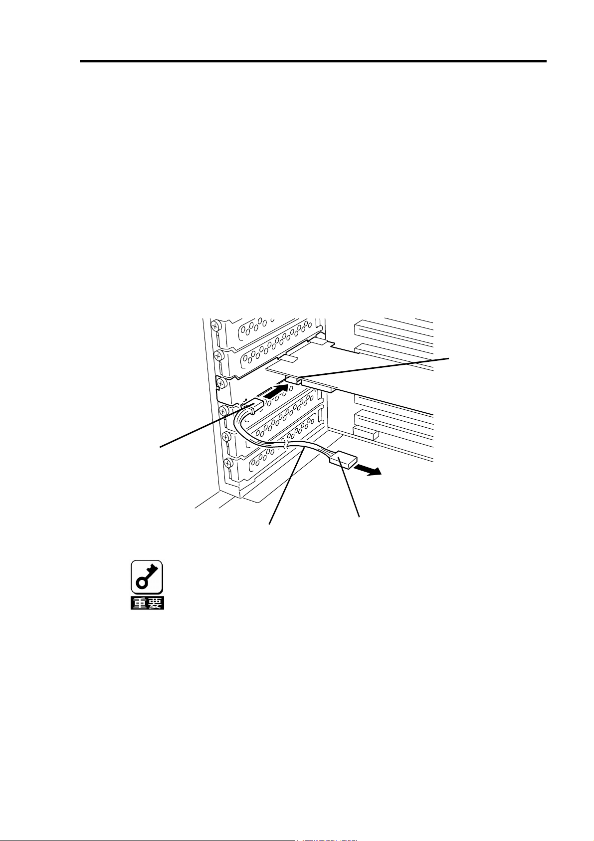
5-6. I2C ケーブルの接続
増設用 HDD ケージを使用する場合は、本製品添付の I2C ケーブルを接続します。I2C ケー
ブルの 3 ピンコネクタ(白)を本製品の I2C コネクタに接続し、4 ピンコネクタ(黒)を増設用
HDD ケージに接続します。増設用 HDD ケージ側の接続先については、増設用 HDD ケー
ジ添付のユーザーズガイドをご覧ください。
増設用 HDD ケージを使用しない場合は、I2C ケーブルを接続する必要はありません。
コネクタ
I2C
ピンコネクタ(白)
3
増設用
I2C
ケーブル
N8154-01 増設用HDD ケージ(S-ATA)にもI2C ケーブルが添付されていま
すが、本製品には使用できません。必ず本製品に添付されているI2C ケー
ブルを使用してください。
4ピンコネクタ(黒)
HDD
ケージへ
Page 33
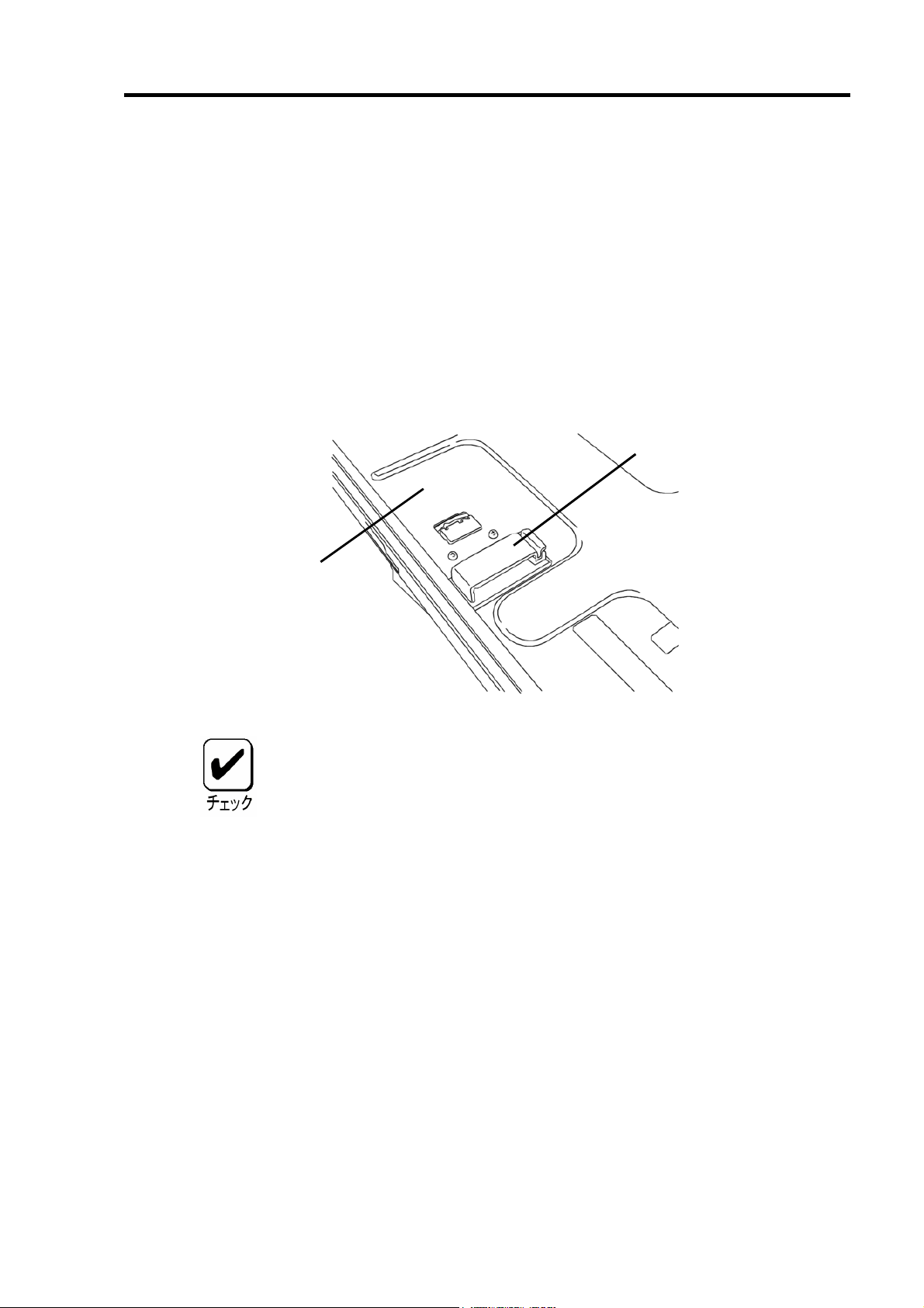
5-7.ケーブルのフォーミング
SATA ケーブルおよび I2C ケーブルを固定するため、以下の手順に従ってケーブルを
フォーミングします。
1. ケーブルクランプの貼付
本製品添付のケーブルクランプを本体装置に貼り付けます。貼り付け位置はケー
ブルをしっかりと固定できる任意の位置に貼り付けてください。本体装置によっ
ては、貼付場所が無く、ケーブルクランプを使用できない場合がありますが、そ
の場合もケーブルを束ねて、バラバラにならないようにフォーミングしてくださ
い。
ケーブルクランプ
13
本体装置の筐体底板
ケーブルクランプを本体装置に貼り付ける前に、貼付箇所を乾いた布等
できれいに拭いてください。
本体装置によっては、本製品添付のケーブルクランプを使用せず、本体
装置の添付品を使用する場合があります。詳しくは、本体装置のユーザー
ズガイドをご覧ください。
Page 34
14
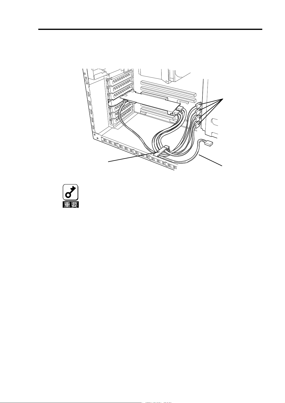
2. ケーブルのフォーミング
ケーブルクランプのロックを解除し、ケーブルを束ねて固定します。
SATA ケーブル
ケーブルクランプ
I2C ケーブル
SATA ケーブルをフォーミングした後、ケーブルに抜けがないこと、コネ
クタに対してまっすぐに接続されていることを確認してください。
Page 35
15
第 2 章 RAID について
ここでは、本製品がサポートしている RAID 機能について説明します。
1. RAID の概要
1-1. RAID(Redundant Array of Inexpensive Disks)とは
直訳すると低価格ディスクの冗長配列となり、ハードディスクドライブ(以降「HDD」と呼
ぶ)を複数まとめて扱う技術のことを意味します。
つまり RAID とは複数の HDD を 1 つのアレイ(ロジカルドライブ)として構成し、これらを
効率よく運用することです。これにより単体の大容量 HDD より高いパフォーマンスを得る
ことができます。
アレイ(ロジカルドライブ)に構成されると、ホストコンピュータからは、複数の HDD が 1
つの HDD として認識されます。ホストコンピュータからのアクセスは、アレイ(ロジカル
ドライブ)を構成している複数の HDD に対して並行して行われます。
また、使用する RAID レベルによっては、ある HDD に障害が発生した場合でも残っている
データやパリティからリビルド機能によりデータを復旧させることができ、高い信頼性を
提供することができます。
1-2. RAID レベルについて
RAID 機能を実現する記録方式には、複数の種類(レベル)が存在します。その中で本製品が
サポートする RAID レベルは、「RAID 0」「RAID 1」「RAID 5」「RAID10」です。ロジカル
ドライブを作成する上で必要となる HDD の数量は RAID レベルごとに異なりますので、下
の表で確認してください。
RAID レベル
RAID 0 1 4
RAID 1 2 2
RAID 5 3 4
RAID 10 4 4
各RAID レベルの詳細は、本章「2.RAID レベル」を参照してください。
必要な HDD 数
最小 最大
Page 36

16
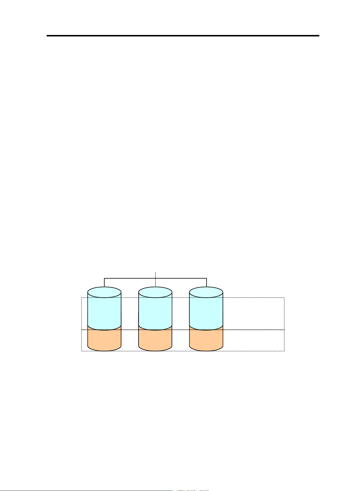
1-3.ロジカルドライブ(Logical Drive)
ロジカルドライブは複数の HDD のグループを表すもので、OS からは物理ドライブとして
認識されます。本製品の設定可能なロジカルドライブの数は、HDD を 4 台実装した場合で
最大 8 個になります。
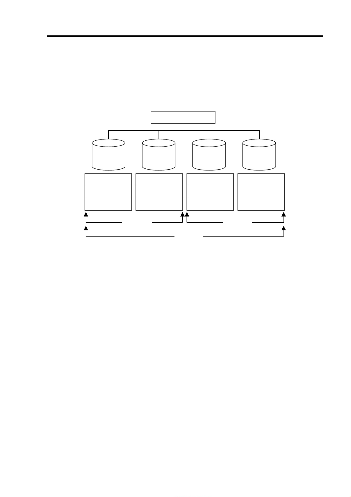
次の図は本製品(ディスクアレイコントローラ)に HDD を 4 台接続し、3 台でロジカルドラ
イブを作成、残りの 1 台をホットスペアディスクに設定した構成例です。
ディスクアレイコントローラ
ロジカルドライブ1
チャネル1
(Port 1)
LD 1-1
チャネル
(Port 2)
チャネル
(Port 3)
チャネル
(Port 4)
2
LD 1-2
3
LD x-x :
LD 1-3
Spare :
4
Spare
ロジカルドライブに割り
当てられた
ホットスペアディスク
HDD
1-4.パリティ(Parity)
冗長データのことです。複数台の HDD のデータから 1 セットの冗長データを生成します。
生成された冗長データは、HDD が故障したときにデータの復旧のために使用されます。
1-5.ホットスワップ
システムの稼働中に HDD の脱着(交換)を手動で行うことができる機能をホットスワップ
といいます。
本製品でホットスワップを行うためには、増設用HDD ケージを接続する必
要があります。
Page 37

17
1-6.ホットスペアディスク(Hot Spare)
ホットスペアディスクとは、冗長性のある RAID レベルで構成されたロジカルドライブ配
下の HDD に障害が発生した場合に、代わりに使用できるように用意された予備の HDD で
す。HDD の障害を検出すると、障害を検出した HDD を切り離し( オフライン)、ホットス
ペアディスクを使用してリビルドを実行します。ホットスペアディスクには以下の 2 種類
の設定があります。
設定 特徴
Global Spare
Dedicated Spare
どのロジカルドライブの HDD が故障した場合でもホットスペアディス
クとして機能します。メディアパトロールを実行することが可能です。
指定したロジカルドライブの HDD が故障した場合のみ、ホットスペア
ディスクとして機能します。メディアパトロールを実行することが可能
です。
ホットスペアディスクを設定するためには、本製品の管理ユーティリティ
Web-based Promise Array Manager(以降「WebPAM」と 呼 ぶ)のインストー
ルが必要です。
ホットスペアディスクを使用したリビルド「スタンバイリビルド」について
は『第3章本製品の機能について』を参照してください。
『Free』ディスクについて
『Free』ディスク(ロジカルドライブやホットスペアディスクに割り当てられていない未構
成の HDD)も、『Global Spare』と同様に、故障した HDD の代わりとして機能します。ホッ
トスペアディスクと『Free』ディスクの両方が存在する構成では、ホットスペアディスク
が優先的に使用されます。
ただし、『Free』ディスクに対しては、メディアパトロールを実行することができないため、
ホットスペアディスクに設定して使用することを推奨します。
Page 38

18
2. RAID レベル
本製品がサポートしている RAID レベルについて詳細な説明をします。
2-1. RAID レベルの特徴
各 RAID レベルの特徴は下表の通りです。
レベル 機 能 冗長性 特 徴
RAID0
RAID1
RAID5
RAID10
ストライピング なし データ読み書きが最も高速
容量が最大
容量=HDD1 台の容量×HDD 台数
ミラーリング あり HDD が 2 台必要
容量=HDD1 台の容量
データおよび冗長データ
のストライピング
ストライピングとミラー
リングの組合せ
あり HDD が 3 台以上必要
容量=HDD1 台の容量×(HDD 台数-1)
あり HDD が 4 台必要
容量=HDD1 台の容量×2
2-2.「RAID0」について
データを各 HDD へ分散して記録します。この方式を「ストライピング」と呼びます。
図ではストライプ 1(Disk1)、ストライプ 2(Disk2)、ストライプ 3(Disk3)・・・というよう
にデータが記録されます。すべての HDD に対して一括してアクセスできるため、最も優れ
たディスクアクセス性能を提供することができます。
RAID0はデータの冗長性がありません。HDDが故障するとデータの復旧が
できません。
アレイコントローラ
Disk 1 Disk 2
ストライプ
1
ストライプ
2
Disk 3
ストライプ
3
ストライプ
4
ストライプ
5
ストライプ
6
Page 39

19
2-3.「RAID1」について
1 つの HDD に対してもう 1 つの HDD へ同じデータを記録する方式です。この方式を「ミ
ラーリング」と呼びます。
1 台の HDD にデータを記録するとき同時に別の HDD に同じデータが記録されます。一方
の HDD が故障したときに同じ内容が記録されているもう一方の HDD を代わりとして使
用することができるため、システムをダウンすることなく運用できます。
アレイコントローラ
Disk 1 Disk 2
ストライプ
ストライプ
1
2
ストライプ
ストライプ
1
2
2-4.「RAID5」について
RAID0 と同様に、データを各 HDD へ「ストライピング」方式で分散して記録しますが、
そのときパリティ(冗長データ)も各 HDD へ分散して記録します。この方式を「分散パリ
ティ付きストライピング」と呼びます。
データをストライプ(x)、ストライプ(x+1)、そしてストライプ(x)とストライプ(x+1)から生
成されたパリティ(x, x+1)というように記録します。そのためパリティとして割り当てられ
る容量の合計は、ちょうど HDD1 台分の容量になります。ロジカルドライブを構成する
HDD のうち、いずれかの 1 台が故障しても問題なくデータが使用できます。
アレイコントローラ
Disk 1 Disk 2 Disk 3
ストライプ
ストライプ
パリティ
(5, 6)
1
4
ストライプ
パリティ
ストライプ
(3, 4)
2
5
パリティ
ストライプ
ストライプ
(1, 2)
3
6
Page 40
20
2-5.「RAID10」について
データを各 HDD へ「ストライピング」方式で分散し、さらにそれらのストライプを「ミ
ラーリング」方式で記録しますので、RAID0 の高いディスクアクセス性能と、RAID1 の
高信頼性を同時に実現することができます。
アレイコントローラ
Disk 1 Disk 2
ストライプ
ストライプ
ストライプ
1
3
5
ストライプ
ストライプ
ストライプ
RAID0 RAID0
2
4
6
RAID1
Disk 3
ストライプ
ストライプ
ストライプ
Disk 4
1
3
5
ストライプ
ストライプ
ストライプ
2
4
6
Page 41

21
第 3 章 本製品の機能について
本製品が持つ機能を説明します。
1.リビルド
リビルド(Rebuild)は、ハードディスクドライブ(以降「HDD」と呼ぶ)に故障が発生した場
合に、故障した HDD のデータを復旧させる機能です。『RAID1』や『RAID5』、『RAID10』
など、冗長性のあるロジカルドライブ対して実行することができます。
1-1.マニュアルリビルド(手動リビルド)
本製品の管理ユーティリティ Web-based Promise Array Manager(以降「WebPAM」と呼ぶ)
を使用し、手動で実施するリビルドです。HDD を選択してリビルドを実行することができ
ます。
詳しい操作方法については、本製品添付の CD-ROM「S-ATA Array Management Software」
内のオンラインマニュアル「Web-based Promise Array Manager ユーザーズガイド」をご
覧ください。
1-2.オートリビルド(自動リビルド)
WebPAM などのユーティリティを使用せず、自動的にリビルドを実行させる機能です。
オートリビルドには、以下の 2 種類の方法があります。
スタンバイリビルド
ホットスペアディスクを用いて自動的にリビルドを行う機能です。ホットスペア
ディスクが設定されている構成では、ロジカルドライブに割り当てられている
HDD に故障が生じたときに、自動的にリビルドが実行されます。
ホットスワップリビルド
故障した HDD をホットスワップで交換することにより、自動的にリビルドが実
行される機能です。
Page 42

22
リビルドを実行する場合は、以下の点に注意してください。
リビルドに使用するHDD は、故障したHDD と同一容量、同一回転数、
同一規格のものを使用してください。
リビルド中は負荷がかかるため、処理速度は低下します。
リビルド中は、本体装置のシャットダウンやリブートを実施しないでく
ださい。万が一、停電などの不慮な事故でシャットダウンしてしまった
場合、速やかに電源の再投入を行ってください。自動的にリビルドが再
開されます。
ホットスワップリビルドを実行するためには、増設用HDD ケージが必要
です。
故障したHDD を抜いてから新しいHDD を実装するまでに、90秒以上の
間隔をあけてください。
ホットスワップリビルドが動作しない場合は、マニュアルリビルドを実
行してください。
Page 43

23
2.メディアパトロール
メディアパトロール(Media Patrol)は、HDD の全領域にリード&ベリファイ試験を実施す
る機能です。メディアパトロールは、ロジカルドライブやホットスペアディスクに割り当
てられているすべての HDD に対して実行することができます。
メディアパトロールにより、HDD の後発不良を検出・修復することができるため、予防保
守として定期的に実施することを推奨します。メディアパトロールはスケジュール設定を
行うことにより、定期的に実施することができます。
『RAID1』や『 RAID5』、『RAID10』など、冗長性のあるロジカルドライブを構成する HDD
やホットスペアディスクに割り当てられた HDD の場合は、実行中に検出したエラーセク
タを修復することができます。冗長性のない『RAID0』のロジカルドライブを構成する HDD
の場合は、エラーセクタを Bad Sector List(BSL)に登録して管理します。
メディアパトロール実行中の HDD へアクセスがあった場合は、メディアパトロールを一
時的に中断し、アクセスが完了すると中断した箇所から継続します。そのため、メディア
パトロールによる性能低下はほとんどありません。
メディアパトロールを実行する場合は、以下の点に注意してください。
頻繁にHDD へアクセスがある環境では、メディアパトロールの処理が進
みません。そのような環境では、メディアパトロールよりもシンクロナ
イズを使った予防保守を推奨します。
メディアパトロールを実施するためにはWebPAM のインストールが必
要です。
詳しい操作方法については、本製品添付のCD-ROM「S-ATA Array
Management Software 」内のオンラインマニュアル「Web-based
Promise Array Manager ユーザーズガイド」をご覧ください。
Page 44

24
3.シンクロナイズ
シンクロナイズ(Synchronization)は、ロジカルドライブの整合性をチェックするための機
能です。『RAID1』や『RAID5』、『RAID10』など、冗長性のあるロジカルドライブ対して
実行することができます。
シンクロナイズは、メディアパトロールと同様、スケジュール設定を行うことにより定期
的に実施することができます。
シンクロナイズは整合性をチェックするだけでなく、メディアパトロールと同様に、実行
中に検出したエラーセクタを修復することができるため、予防保守として使用できます。
シンクロナイズはメディアパトロールとは異なり、実行中のロジカルドライブに対してア
クセスがあった場合でも一定の割合で処理を継続します。そのため、シンクロナイズ実行
中はシステムに負荷がかかり、処理速度が低下する場合があります。ただし、頻繁にアク
セスがある環境では、メディアパトロールの処理を進めることができないため、シンクロ
ナイズを使った予防保守を推奨します。
シンクロナイズを実行する場合は、以下の点に注意してください。
シンクロナイズを実施するためにはWebPAM のインストールが必要で
す。
詳しい操作方法については、本製品添付のCD-ROM「S-ATA Array
Management Software 」内のオンラインマニュアル「Web-based
Promise Array Manager ユーザーズガイド」をご覧ください。
Page 45

25
4.エクスパンション
エクスパンション(Expansion)は、既存のロジカルドライブに HDD を追加し、ロジカルド
ライブの容量を拡大する機能です。
エクスパンションを実行する場合は、以下の点に注意してください。
エクスパンション実行前に、必ずデータのバックアップとシンクロナイ
ズを実施してください。
エクスパンション中は負荷がかかるため、処理速度は低下します。
クリティカル(Critical)状態のロジカルドライブには実行できません。リビ
ルドを実行し、ロジカルドライブを復旧した後で、エクスパンションを
実行してください。
エクスパンション中は、本体装置のシャットダウンやリブートを実施し
ないでください。万が一、停電等の不慮の事故でシャットダウンをして
しまった場合は、速やかに電源を再投入してください。再起動後、自動
的にエクスパンションが開始されます。
エクスパンションを実施するためにはWebPAM のインストールが必要
です。
詳しい操作方法については、本製品添付のCD-ROM「S-ATA Array
Management Software 」内のオンラインマニュアル「Web-based
Promise Array Manager ユーザーズガイド」をご覧ください。
Page 46

26
例) RAID5 のロジカルドライブのエクスパンション
以下は、80GB HDD×3 台で構成された RAID5 のロジカルドライブに、80GB HDD を 1
台追加する場合の例です。
ロジカルドライブ(
80GB 80GB 80GB
ロジカルドライブ(
80GB 80GB 80GB
RAID5
RAID5
)
エクスパンション実行
)
80GB
80GB
【実行前】
容量
= 160GB
【実行後】
容量
= 240GB
Page 47

27
第 4 章 ランプ表示について
本製品は、増設用 HDD ケージと接続することでハードディスクドライブ(以降「HDD」
と呼ぶ)のアクセス状態や、故障やリビルド動作中などのステータスを確認することがで
きます。また、本体装置添付の LED ケーブルを接続することで、アクセス時に本体装置前
面の DISK ACCESS ランプを点滅させることができます。
1.本体装置のランプ表示
ランプ ランプ表示 意味
消灯 HDD にアクセスしていません。 DISK ACCESS ランプ
(緑色)
アクセスしていない状態でも、ディスクアクセスランプが頻繁に点滅する場
合がありますが故障ではありません。
アクセスがない状態でも、ESMPRO や本製品自身が行っている監視による
アクセス、OS からアクセスが定期的に行われているためです。また、本製
品の性質上、1回のアクセスに対する点滅時間が長いため、これらのアクセ
スに対して頻繁に点滅する場合があります。
本体装置のランプ表示は本体装置の種類によって異なります。詳しくは本体
装置のユーザーズガイドを参照してください。
点滅 HDD にアクセスをしています。
!
DISK ACCESS ランプ
Page 48
28
2.トレーのディスクランプ表示
ディスクランプ ランプ表示 意味
消灯 HDD にアクセスしていません。 緑色
高速点滅 HDD にアクセスしています。
アンバー色
立ち上げ時に点灯 HDD に電源が供給されています。HDD の故障ではあり
ません。
稼動中に点灯 HDD が故障しているか、SATA ケーブルが抜けているこ
とを示しています。もし、HDD が故障している場合は直
ちに新しい HDD に交換し、リビルド処理を行ってくださ
い。
低速点滅 リビルド処理が行われていることを示しています。
アクセスしていない状態でも、緑色ランプが頻繁に点滅する場合があります
が故障ではありません。
アクセスがない状態でも、ESMPRO や本製品自身が行っている監視による
アクセス、OS からアクセスが定期的に行われているためです。また、本製
品の性質上、1回のアクセスに対する点滅時間が長いため、これらのアクセ
スに対して頻繁に点滅する場合があります。
本体装置によっては、増設用HDDケージが接続できなかったり、接続で
きる増設用HDDケージが異なったりします。詳しくは、お買い求めの販
売店にお問い合わせください。
ディスクランプの表示は、ドライバによって制御されています。OS イ
ンストール時、または、本体装置の起動毎にアンバー色ランプが点灯し
ますが、故障ではありません。OS が立ち上がり、ドライバが動作する
とアンバー色ランプは消灯します。
再起動時には、再起動時のランプの表示状態が保持されたまま再起動し
ます。
トレー
増設用
HDD
ケージ
ディスクランプ
Page 49

29
第 5 章 ロジカルドライブの作成
ここでは本製品のコンフィグレーションユーティリティ「FastBuild Utility」について説明
します。
1.FastBuild Utility を使用する前に
「FastBuild Utility」を使用する前に、サポート機能および注意事項をご覧ください。
1-1.サポート機能
ハードディスクドライブ(以降「HDD」と呼ぶ)のモデル名/容量の情報表示
HDD の割り当て状態表示
ロジカルドライブの作成
RAID レベルの設定
Stripe Block サイズの設定
Fast Initialize の設定
Gigabyte Boundary の設定
Cache Mode の設定
ロジカルドライブの設定情報・ステータスの表示
ロジカルドライブの削除
エラー検出時の起動方法設定(Halt On Error)
システムリソース情報の表示
スプリット機能
『スプリット機能』とは
本製品は、1 台の HDD を最大 2 個まで分割して使用することができるスプリット機能を
サポートしています。分割された HDD はそれぞれ『Extent 1』『Extent 2』と表示されま
す。本ユーティリティ上では、ロジカルドライブ作成時に任意の容量を指定することで、
自動的にスプリット機能が使用され、HDD が分割されます。
Page 50
30
1-2.ロジカルドライブ作成時の注意事項
ホットスペアディスクの設定について
本ユーティリティではホットスペアディスクの設定はできません。ホットスペア
ディスクを設定する場合は、OS インストール後に本製品の管理ユーティリティ
Web-based Promise Array Manager(以降「WebPAM」と 呼 ぶ )から設定してくださ
い。
なお、ロジカルドライブに割り当てられていない『Free』の状態の HDD でもス
タンバイリビルドが実施されますが、『Free』ディスクに対してはメディアパト
ロールが実施されませんので、WebPAM からスペアディスクに設定することを推
奨します。
スプリット機能を使用したロジカルドライブ構成について
本製品では、スプリット機能のサポートにより様々なロジカルドライブ構成を作
成することができますが、中にはトラブルの原因となりうる構成もありますので
注意してください。以下に推奨する構成とサポート外の構成の例を挙げますので、
確認してからロジカルドライブを作成してください。
(1) 推奨するスプリット構成
(1-1) 同一容量の HDD で同一の RAID レベルが作成された構成
アレイコントローラ
LD1-1
80GB
LD2-1
40GB
ディスク
(120GB)
LD1-2
80GB
LD2-2
40GB
1
ディスク
(120GB)
2
LD1-3
80GB
LD2-3
40GB
ディスク
(120GB)
RAID5
サイズ
LD
RAID5
サイズ
LD
3
: 160GB
: 80GB
Page 51

(2) サポート外のスプリット構成
(2-1)異なる RAID レベルが作成された構成(その 1)
アレイコントローラ
31
LD1-1
80GB
LD2-1
40GB
HDD 1
(120GB)
LD1-2
80GB
LD2-2
40GB
HDD 2
(120GB)
(120GB)
(2-2)異なる RAID レベルが作成された構成(その 2)
アレイコントローラ
RAID1
サイズ
LD
: 40GB
LD1-1
80GB
LD2-1
40GB
LD1-2
80GB
LD2-2
40GB
LD1-3
80GB
LD3-1
40GB
LD1-3
80GB
LD2-3
40GB
HDD 3
L
RAID5
サイズ
LD
RAID0
サイズ
LD
LD1-4
80GB
LD3-2
40GB
: 160GB
: 120GB
RAID5
LD
RAID1
LD
サイズ
サイズ
: 240GB
: 40GB
HDD 1
(120GB)
HDD 2
(120GB)
(2-3)異なる台数の HDD で作成された構成
アレイコントローラ
RAID5
サイズ
LD
: 80GB
LD1-1
80GB
LD2-1
40GB
HDD 1
(120GB)
LD1-2
80GB
LD2-2
40GB
HDD 2
(120GB)
HDD 3
(120GB)
LD1-3
80GB
LD2-3
40GB
HDD 3
(120GB)
HDD 4
(120GB)
LD1-4
80GB
Free
40GB
HDD 4
(120GB)
RAID5
サイズ
LD
: 240GB
Page 52

32
(2-4)異なる容量の HDD で作成された構成
アレイコントローラ
LD1-1
80GB
RAID1
サイズ
LD
: 40GB
LD1-1
40GB
HDD 1
(120GB)
(2-5)異なる HDD で作成された構成
RAID5
サイズ
LD
: 120GB
LD1-1
60GB
Free
60GB
LD1-2
80GB
LD1-2
40GB
HDD 2
(120GB)
アレイコントローラ
LD1-2
60GB
LD1-1
60GB
LD1-3
80GB
HDD 3
(80GB)
LD1-3
60GB
LD1-2
60GB
LD1-4
80GB
HDD 4
(80GB)
Free
60GB
LD1-3
60GB
RAID5
サイズ
LD
RAID5
サイズ
LD
: 240GB
: 120GB
HDD 1
(120GB)
HDD 2
(120GB)
HDD 3
(120GB)
HDD 4
(120GB)
Page 53

33
2. FastBuild Utility の起動とメニュー
2-1. FastBuild Utility の起動
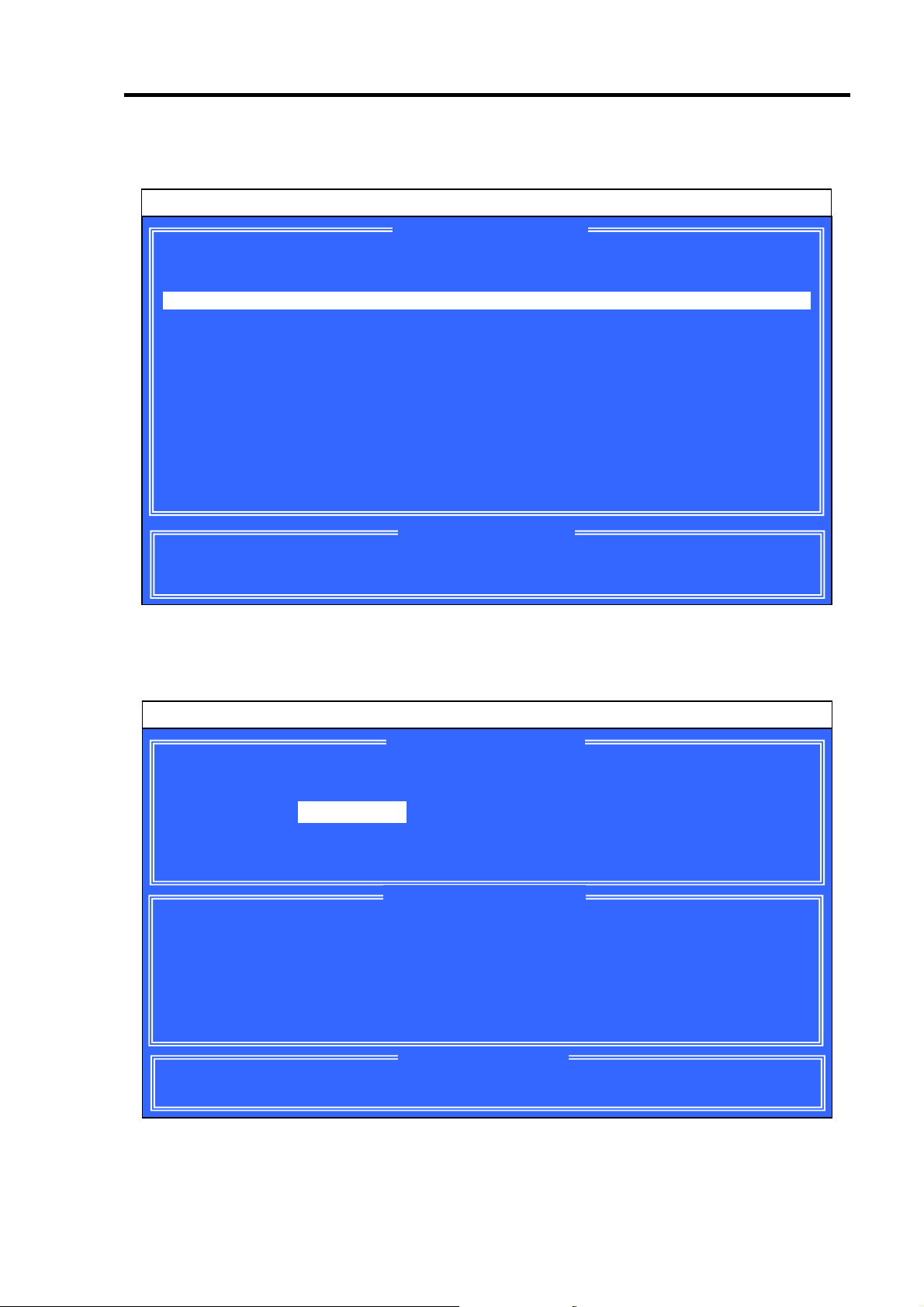
以下の POST 画面が表示されたら<Ctrl>+<F>キーを押して FastBuild Utility を起動します。
【POST 画面イメージ(ロジカルドライブ未設定時)】
FT SX4100 (tm) BIOS Version x.x.xxxx.xx
(c) xxxx-xxxx Promise Technology, Inc. All rights reserved.
Installed ECC DIMM: 64M
No Array is defined...
Press <Ctrl-F> to enter FastBuild (tm) Utility...
POST 中は<Pause>キーなどの操作に関係ないキーを押さないでくださ
い。
Page 54

34
2-2. Main Menu
FastBuild Utility を起動すると最初に表示される[Main Menu]画面です。ここから各種設定
を行うため<1>~<4>キーを押して画面を切り換えます。
<1>~<4>キーの入力は、標準キーボードから入力してください。テンキー
からの入力は出来ません。
FastBuild (tm) Utility (c) xxxx-xxxx Promise Technology, Inc.
View Drive Assignments..............[ 1 ]
Define LD...........................[ 2 ]
Delete LD...........................[ 3 ]
Controller Configuration............[ 4 ]
Press 1..4 to Select Option [ESC] Exit
[View Drive Assignments]
[ Main Menu ]
[ Keys Available ]
HDD の情報とロジカルドライブの構成情報を確認することができます。
[Define LD]
新規ロジカルドライブの設定することができます。また、既存のロジカルドライ
ブの情報・ステータスを確認することもできます。
[Delete LD]
ロジカルドライブを削除することができます。
[Controller Configuration]
POST 中にエラーを検出した場合の起動方法を設定することができます。また、
システムリソース情報を確認することもできます。
Page 55

35
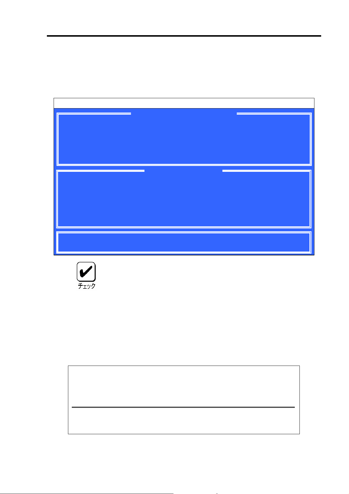
2-3. View Drive Assignments
[Main Menu]で<1>キーを押すと以下の[View Drive Assignments]画面が表示されます。この
画面では、HDD の情報とロジカルドライブの構成状態を確認することができます。
各チャネルの移動は矢印キー『↑』『↓』で移動します。情報のみの表示な
ので設定項目はありません。
例) HDD を 4 台接続し、2 台で RAID1 のロジカルドライブを 2 個設定し、1 台で
RAID0 のロジカルドライブを作成した構成
FastBuild (tm) Utility (c) xxxx-xxxx Promise Technology, Inc.
Channel:ID Drive Model Capacity (MB) Assignment
1:Mas MAXTOR 6Y080MO 80001
Extent 1 40000 LD 1-1
Extent 2 39933 LD 2-1
2:Mas MAXTOR 6Y080MO 80001
Extent 1 40000 LD 1-2
Extent 2 39933 LD 2-2
3:Mas MAXTOR 6Y080MO 80001
Extent 1 79933 LD 3-1
4:Mas MAXTOR 6Y080MO 80001
Extent 1 79933 Free
↑] Up [↓] Down [ESC] Exit
[
[Channel: ID]
[ View Drives Assignments ]
[ Keys Available ]
ボード上の SATA コネクタのチャネル番号に対応しています。
[Drive Model]
HDD のモデル名が表示されます。
[Capacity]
HDD の容量を MB 単位で表示しています。『Extent 1』と『Extent 2』は、スプリッ
ト機能により分割された HDD を表し、それぞれの容量が表示されます。分割し
ていない HDD は『Extent 1』と表示されます。
Page 56
36
[Assignment]
HDD のロジカルドライブの構成状態が表示されます。
Assignment
LD x-y
Free
意味
正常に動作可能であり、ロジカルドライブの一部として設定されてい
る状態。
『x』はロジカルドライブ番号を示します。
『y』はロジカルドライブ内での HDD の割り当て番号を示します。
「Assignment」が『Free』になっている場合は、以下の 3 通りのディ
スクに該当します。
ロジカルドライブに割り当てられていないディスク
オフラインになっているディスク
スペアディスク
HDD のモデル名の欄の容量と『Extent x』の欄に表示される容量とでは、
『Extent x』の欄の容量の方が少なく表示されます。これは、モデル名の欄
の容量が使用しているHDD の全容量を表示しているのに対して、『Extent
x』の欄の容量は本製品が使用する管理領域を除いた容量を表示しているた
めです。
Page 57

37
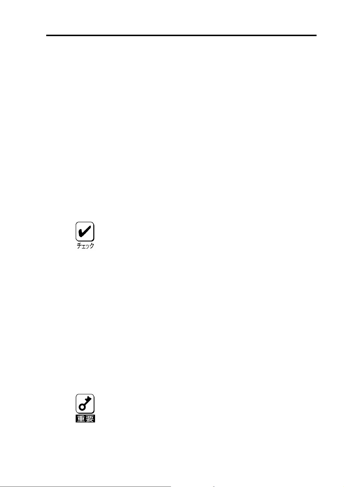
2-4. Define LD
[Main Menu]で<2>キーを押すと以下の[Define LD Menu]画面が表示されます。
この画面ではロジカルドライブの新規作成および既存のロジカルドライブの情報・ステー
タスの確認もできます。
例)HDD3 台での RAID5 構成
FastBuild (tm) Utility (c) xxxx-xxxx Promise Technology, Inc.
LD No RAID Mode Total Drv Capacity (MB) Status
LD 1 RAID 5 3 159866 Functional
LD 2 ---- ---- ------ --- LD 3 ---- ---- ------ --- LD 4 ---- ---- ------ --- LD 5 ---- ---- ------ --- LD 6 ---- ---- ------ --- LD 7 ---- ---- ------ --- LD 8 ---- ---- ------ ----
[ Define LD Menu ]
[↑] Up [↓] Down [ESC] Exit [Enter] Select
[LD No]
[ Keys Available ]
ロジカルドライブの番号を示しています。
[RAID Mode]
ロジカルドライブの RAID レベルを示します。
[Total Drv]
ロジカルドライブ構成下の HDD の数量を示しています。
[Capacity]
ロジカルドライブ構成の論理容量を MB 単位で示しています。
[Status]
ロジカルドライブのステータスを示しています。
Status
Functional
Critical
Rebuilding
Off Line
意味
ロジカルドライブを構成しているすべての HDD が正常に動作
している状態です。
ロジカルドライブを構成している HDD のうち 1 台がオフライ
ンになっている状態です。冗長性がなくなっていますので、早
急にリビルドする必要があります。クリティカルの状態で他の
HDD が故障すると、データの復旧ができなくなります。
ロジカルドライブがリビルド中の状態です。
ロジカルドライブを構成している HDD のうち 2 台以上がオフ
ラインになっている状態です。オフラインのロジカルドライブ
は、データ処理ができません。
Page 58

38
2-5. Delete LD
[Main Menu]で<3>キーを押すと以下の[Delete LD Menu]画面が表示されます。この画面か
らロジカルドライブの削除を実行することができます。
例)HDD3 台での RAID5 構成
FastBuild (tm) Utility (c) xxxx-xxxx Promise Technology, Inc.
LD 1 RAID 5 3 159866 Functional
LD 2 ---- ---- ------ --- LD 3 ---- ---- ------ --- LD 4 ---- ---- ------ --- LD 5 ---- ---- ------ --- LD 6 ---- ---- ------ --- LD 7 ---- ---- ------ --- LD 8 ---- ---- ------ ----
[↑] Up [↓] Down [ESC] Exit [Del or Alt+D] Delete
[ Delete LD Menu ]
[ Keys Available ]
Delete LD(ロジカルドライブの削除)の実行手順
矢印キー『↑』『↓』を使い、削除する対象のロジカルドライブにカーソルを移動
1.
します。
2. <Del>キーまたは<Alt>+<D>キーを押します。
3. 以下のメッセージが表示されます。ロジカルドライブを削除する場合は
<Ctrl>+<Y>キーを押します。中止する場合は、任意のキー(<Esc>キーなど)を押し
てキャンセルしてください。
Press Ctrl-Y to delete the data in the disk!
or press any other key to abort...
Page 59
39
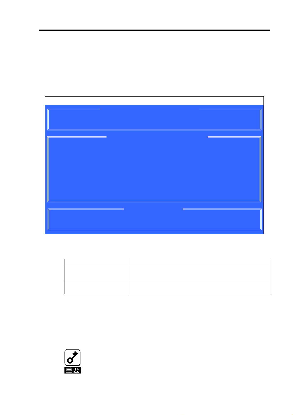
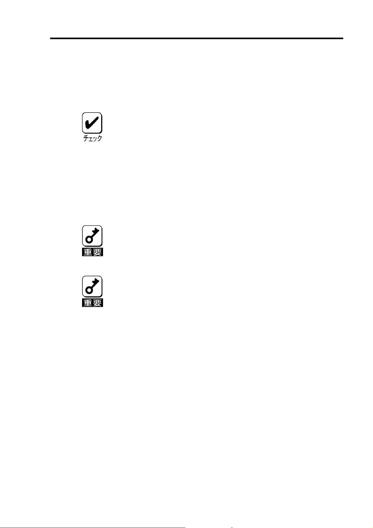
2-6. Controller Configuration
[Main Menu]で<4>キーを押すと以下の画面が表示されます。
この画面からエラー検出時の起動方法の設定、およびシステムリソースの確認を行うこと
ができます。
FastBuild (tm) Utility (c) xxxx-xxxx Promise Technology, Inc.
Halt On Error : Disable
Installed Memory Address : DEDF8000 Size : 64M
Controller IRQ : 10
ATA IO Address : D800
XOR and HDMA IO Address : D400
Sequence Control IO Address : D000
Flash and SRAM Memory Address : DEE00000
[←,,Space] Change Option [ESC] Exit
[Halt On Error]
[ Adapter Configuration - Options ]
[ System Resources Configuration ]
[ Keys Available ]
POST 中にエラーを検出した場合の起動方法を設定することができます。
Halt On Error
Disable(推奨値) 故障した HDD を切り離し、クリティカル状態で起動しま
Enable
起動時の動作
す。
起動処理を停止します。起動を継続させためには手動で
<Esc>キーを押す必要があります。
Halt On Error の設定手順
1.
[Main Menu]から<4>キーを押して[Controller Configuration]を立ち上げます。
2. 設定値にカーソルを合わせて、<Space>キーまたは矢印キー『←』を押します。
3. 設定変更後、<Esc>キーで[Main Menu]に戻ってください。
設定変更後、[Main Menu]に戻らずに本体装置の電源をOFF した場合や、
<Ctrl>+<Alt>+<Del>キーで再起動した場合は、設定変更が反映されません。
Page 60

40
2-7. FastBuild Utility の終了
1. <Esc>キーを押し[Main Menu]画面まで戻ります。
2. [Main Menu]の表示画面で<Esc>キーを押すと FastBuild Utility の終了を確認する
メッセージが表示されます。
System is going to REBOOT!
Are You Sure?
Y – Reboot / Any key - Back
3. FastBuild Utility を終了させる場合は、<Y>キーを押して本体装置を再起動させる
か、電源を OFF にしてください。終了させない場合は、任意のキー(<Esc>キー
など)を押してキャンセルしてください。
Page 61

41
3.ロジカルドライブの作成
ここでは FastBuild Utility 上でロジカルドライブ作成するときの操作について説明します。
3-1.ロジカルドライブの作成作業フロー
ロジカルドライブの
作成開始
FastBuild Utility
既存のロジカル
ドライブがある?
Yes
ロジカルドライブの
追加?
No
ロジカルドライブを削除する
の接続確認
HDD
ロジカルドライブの作成
の起動
No
Yes
z[
Delete LD
「
2-5. Delete LD
[
z
View Drive Assignments
1) ”Free”
2) Disk
z[
Define LD
1) RAID
2) Stripe Block
3) Fast InitのON/OFF
4) Gigabyte Boundary OFF
5) Cache Mode
]
で認識されているか
の容量確認
]
レベルの設定
」参照
]
の設定
設定
確認
の設定
起動方法の設定
本体装置の再起動
ロジカルドライブの
作成終了
[
z
Controller Configuration
1) Halt On Error
]
の設定
Page 62
42
3-2. FastBuild Utility の設定項目
「FastBuild Utility」の設定項目一覧です。
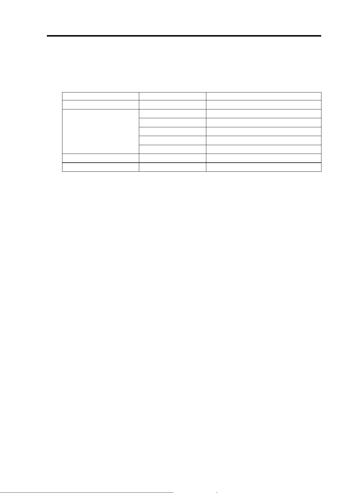
メニュー 設定項目 備 考
View Drive Assignments –
Define LD
Delete LD –
Controller Configuration Halt On Error
RAID Mode
Stripe Block
Fast Init
Gigabyte Boundary
Cache Mode
HDD の情報表示
RAID レベルを設定します
Strip Block サイズを設定します
Fast Initialize の実施を設定します
GB 単位での容量を設定します
Write Cache のモードを設定します
ロジカルドライブを削除します
エラー検出時の起動方法を設定します
Page 63

3-3.ロジカルドライブの作成方法
1. FastBuild Utility を起動します。
2. [Main Menu] で<1>キーを押して[View Drive Assignments]を立ち上げます。
FastBuild (tm) Utility (c) xxxx-xxxx Promise Technology, Inc.
43
Channel:ID Drive Model Capacity (MB) Assignment
1:Mas MAXTOR 6Y080MO 80001
Extent 1 79933 Free
2:Mas MAXTOR 6Y080MO 80001
Extent 1 79933 Free
3:Mas MAXTOR 6Y080MO 80001
Extent 1 79933 Free
4:Mas MAXTOR 6Y080MO 80001
Extent 1 79933 Free
[↑] Up [↓] Down [ESC] Exit
[ View Drives Assignments ]
[ Keys Available ]
3. 各チャネルに接続した HDD の接続状態を確認します。
【確認項目】
ディスクアレイコントローラに接続されているHDD がすべて認識されているか。
HDD の容量が正しく表示されているか。また、すべて同一容量か。
「Assignment」の表示がすべて「Free」で表示されているか。
容量が異なるHDD が接続されている場合は、保守サービス会社かお買い
求めの販売店まで連絡願います。
新品のHDD 、あるいは保守交換用のHDD を接続した場合で、
「Assignment」が「LD x-x」と表示された場合は、保守サービス会社か
お買い求めの販売店に連絡願います。
4. すべての HDD が正しく表示/接続されていることが確認できたら<Esc>キーを押
して[Main Menu]に戻ります。
Page 64
44
5. [Main Menu]で<2>キーを押して[Define LD Menu]を立ち上げます。
FastBuild (tm) Utility (c) xxxx-xxxx Promise Technology, Inc.
[ Define LD Menu ]
LD No RAID Mode Total Drv Capacity (MB) Status
LD 1 ---- ---- ------ ----
LD 2 ---- ---- ------ --- LD 3 ---- ---- ------ --- LD 4 ---- ---- ------ --- LD 5 ---- ---- ------ --- LD 6 ---- ---- ------ --- LD 7 ---- ---- ------ --- LD 8 ---- ---- ------ ----
[↑] Up [↓] Down [ESC] Exit [Enter] Select
[ Keys Available ]
6. 作成する「LD No」に矢印キー『↑』『↓』でカーソルを合わせ、<Enter>キーを押
すと以下の[Define LD Menu] 画面が表示されます。通常「LD No」は「LD 1」から使
用してください。
FastBuild (tm) Utility (c) xxxx-xxxx Promise Technology, Inc.
[ Define LD Menu ]
LD No RAID Mode Total Drv
LD 1 RAID 5 0
Stripe Block: 64 KB Fast Init: OFF
Gigabyte Boundary: OFF Cache Mode: AutoSwitch
[ Drives Assignments ]
Channel:ID Drive Model Capacity (MB) Assignment
1:Mas MAXTOR 6Y080MO 80001 N
2:Mas MAXTOR 6Y080MO 80001 N
3:Mas MAXTOR 6Y080MO 80001 N
4:Mas MAXTOR 6Y080MO 80001 N
[ Keys Available ]
[↑] Up [↓] Down [ESC] Exit [Space] Change Option [Ctrl-Y] Save
Page 65

7. [Define LD Menu]で「RAID Mode」、「Stripe Block」、「Fast Init」、「Gigabyte
Boundary」の設定を行います。設定値は矢印キー『↑』『↓』でカーソルを対象の
項目に移動し、<Space>キーを押して変更します。
設定項目 初期値 設定可能値
RAID Mode (RAID レベル)
Stripe Block 64KB/NA 32KB/64KB/128KB/NA(*)
Fast Init OFF ON/OFF
Gigabyte Boundary OFF ON/OFF
Cache Mode AutoSwitch AutoSwitch/WriteBack/WriteThru
*: RAID レベルによっては「NA」と表示され、変更できない場合があります。
[RAID Mode]
RAID レベルを設定します。目的に合わせて RAID レベルを選択してください。
[Stripe Block]
ストライピングを行う際のデータ分割の単位です。設定値が大きいほどシーケン
シャルデータの読み書きが高速になります。64KB での使用を推奨します。
RAID5 RAID0/RAID1/RAID5/RAID10
45
[Fast Init]
本設定を『ON』に設定すると、ロジカルドライブ作成時にマスターブートレコー
ド(MBR)を初期化します(Fast Initialization 機能)。HDD 内のデータを消去する場
合は『ON』に設定してください。また、OS の再インストールを実施する場合も
『ON』に設定してください。「Fast Init」を実施しなくても OS の再インストール
は可能ですが、パーティションのフォーマットで時間がかかる場合があります。
[Gigabyte Boundary]
ロジカルドライブ設定時に、HDD の容量を GB 未満の容量を切り捨てて、GB 単
位でまるめる機能です。常に『OFF』に設定してください。
[Cache Mode]
ディスクアレイコントローラの「Write Cache」のモードを設定します。それぞれ
の設定値の仕様は、下の表を参照してください。
Cache Mode
AutoSwitch
(デフォルト値)
Write Back
Write Thru
仕様
増設バッテリが接続され残量が十分にあり正常に動作している場合
は「Write Back」で動作しますが、バッテリが未接続の場合や残量が
少ない場合、バッテリの異常が検出された場合には自動的に「Write
Thru」に切り替わるため、電源断時でもデータを保護します。常に
AutoSwitch で使用することを推奨しています。
本製品上のキャッシュメモリに一旦データを書き込み、そのキャッ
シュメモリのデータを元に HDD へデータの書き込みを行う非同期の
制御方式です。「Write Thru」 よりアクセス性能が向上しますが、
電源瞬断などの不慮の事故が発生した際に、データを損失する危険性
があります。
本製品上のキャッシュメモリと HDD の両方にデータの書き込みを行
う制御方式です。一般的に「Write Back」よりアクセス性能は劣りま
す。
Page 66

46
8. 設定項目の設定が完了したら、[Devices Assignments]で作成するロジカルドライ
ブに使用する HDD を選択します。矢印キー『↑』『↓』で対象の HDD にカーソ
ル移動し、<Space>キーを押します。[Assignment]の表示が『N』→『Y』に変更
されると HDD がロジカルドライブに割り当てられたことを意味します。
9. ロジカルドライブの設定がすべて完了したら<Ctrl>+<Y>キーを押して構成情報を
保存します。
10. 「Fast Init」の 設 定 を『 ON』に設定した場合、以下のメッセージが表示されます。
Fast Initialization を実施する場合は、再度<Ctrl>+<Y> キーを押します。Fast
Initialization を実施しない場合は、その他の任意のキー(<Esc>キーなど)を押しま
す。
Fast Initialization Option has been selected.
It will erase the MBR data of the disks.
<Press Ctrl-Y Key if you are sure to erase it>
<Press any other key to ignore this option>
11. 次に以下のメッセージが表示されます。スプリット機能を使用し HDD を分割し
て使用する場合は、<Ctrl>+<Y>キーを押します。分割せずに最大容量のロジカル
ドライブを作成する場合は、その他の任意のキー(<Esc>キーなど)を押します。
すでに分割した HDD を使用してロジカルドライブを作成する場合は本メッセー
ジが表示されません。自動的に残りすべての容量を使用します。
Press Ctrl-Y to Modify Array Capacity or press any
Other key to use maximam capacity...
12. 手順 11 で<Ctrl>+<Y>キーを押した場合は、以下のメッセージが表示されます。ロ
ジカルドライブの容量を MB 単位で入力します。入力後<Enter>キーを押して確
定します。
Enter array capacity (in MB) here: 80000_
Page 67
13. ロジカルドライブ作成後、以下の[Define LD Menu]画面が表示されます。作成し
たロジカルドライブの情報を確認したい場合は、カーソルを対象のロジカルドラ
イブに移動し<Enter>キーを押してください。[View LD Definition Menu]画面が表
示されます。前画面に戻る場合は<Esc>キーを押します。
FastBuild (tm) Utility (c) xxxx-xxxx Promise Technology, Inc.
47
LD No RAID Mode Total Drv Capacity(MB) Status
LD 1 RAID 5 4 80000 Functional
Stripe Block: 64 KB Cache Mode: AutoSwitch
Channel:ID Drive Model Capacity (MB) Assignment
1:Mas MAXTOR 6Y080MO 80001 N
2:Mas MAXTOR 6Y080MO 80001 N
3:Mas MAXTOR 6Y080MO 80001 N
4:Mas MAXTOR 6Y080MO 80001 N
「FastBuild Utility」のロジカルドライブ容量に比べ、OS 上ではロジカルド
ライブ容量が小さく見えます。これは「FastBuild Utility」が1GB=10003Byte
換算しているのに対し、OS は1GB=10243Byte 換算しているためです。
[ View LD Definition Menu ]
[ Drives Assignments ]
Any Key to Continue.......
14. 続けてロジカルドライブを作成する場合は、再度同様の手順を行ってください。
15. ロジカルドライブの設定が完了したら、FastBuild Utility を終了させて、本体装置
を再起動させてください。
16. 本体装置の再起動中、以下の POST 画面が表示されます。「STATUS」が
『Functional』になっていることを確認してください。
例)HDD4 台で RAID5 構成のロジカルドライブ
FT SX4100 (tm) BIOS Version x.x.xxxx.xx
(c) xxxx-xxxx Promise Technology, Inc. All rights reserved.
Installed ECC DIMM 64M
ID MODE SIZE TRACK-MAPPING STATUS
1 3+0 RAID 5 239799M 29153/255/63 Functional
Press <Ctrl-F> to enter FastBuild (tm) Utility...
Page 68

48
第 6 章 運用・保守
1.保守サービス
保守サービスは NEC の保守サービス会社、および NEC が指定した保守サービス会社に
よってのみ実施されますので、純正部品の使用はもちろんのこと、技術力においてもご安
心の上、ご都合にあわせてご利用いただけます。
なお、お客さまが保守サービスをお受けになる際のご相談は、弊社営業担当または代理店
で承っておりますのでご利用ください。
2.予防保守
2-1.データのバックアップ
万が一の場合に備え、定期的にハードディスクドライブ(以降「HDD」と呼ぶ)内のデータ
をバックアップすることをお勧めします。
データのバックアップについては、本体装置のユーザーズガイドをご覧ください。
2-2.メディアパトロール/シンクロナイズによる予防保守
HDD の後発不良に対する予防保守として、メディアパトロールやシンクロナイズを定期的
に実施することをお勧めします。これらの機能により、HDD の後発不良を早期に発見し修
復することができます。どちらの機能も、Web-based Promise Array Manager(以降
「WebPAM」と呼ぶ)のスケジュール機能により定期的に実施することができます。
メディアパトロールとシンクロナイズの詳しい機能については、『第 3 章本製品の機能に
ついて』をご覧ください。
スケジュールの間隔は週に 1 度実施されることを推奨していますが、お客さまの運用状況
に合わせ、少なくとも月に 1 度は実施されることをお勧めしています。
メディアパトロールやシンクロナイズを実施するためには、WebPAM のイ
ンストールが必要になります。
Page 69
49
3.保守機能について
本製品で以下の保守機能をサポートしています。
Configuration on Disk(COD)機能
リビルド機能
クリティカルブート機能
3-1. Configuration on Disk(COD)機能
Configuration on Disk (COD)機能は、コンフィグレーション情報を HDD 内部に記録する機
能です。この機能により、万一ディスクアレイコントローラが故障し、ディスクアレイコ
ントローラの交換を行っても、コンフィグレーション情報が失われることはありません。
ディスクアレイコントローラ交換後、コンフィグレーション情報を HDD から読み込み、
正常に動作させることが可能です。
本製品はコンフィグレーション情報をディスクアレイコントローラ内に保
存しません。コンフィグレーション情報は、すべてHDD 内に記録/保存され
ます。
3-2.リビルド機能
リビルド機能は、HDD に故障が発生した場合に、故障した HDD のデータを復旧させる機
能です。『RAID1』や『RAID5』、『RAID10』など、冗長性のあるロジカルドライブ対して
実行することができます。
詳しくは『第 3 章.本製品の機能について』をご覧ください。
3-3.クリティカルブート機能
本製品は、本体装置の起動時にシステムドライブを構成している HDD に異常が発生し正
常に応答しなかった場合、異常となっている HDD を自動的に排他し、本体装置を起動さ
せるクリティカルブート機能をサポートしています。
「クリティカルブート機能」を有効にするためには「FastBuild Utility」の 設
定項目「Halt On Error」機能を”Disable”に設定しておく必要があります。詳細
は『第5章ロジカルドライブの作成』をご覧ください。
Page 70
50
4.本製品の交換
本装置を交換する際は以下の手順に従ってください。
本体装置の取り扱いについては、本体装置のユーザーズガイドをご覧くださ
い。
1. 本体装置の電源を OFF にして、電源コードをコンセントから抜きます。電源が
ON になっている場合は、OS のシャットダウン処理を行った後、本体装置の電源
を OFF にして電源コードをコンセントから抜いてください。
2. 本体装置のサイドカバーや部品等を取り外します。
3. 本製品に接続されているケーブル(SATA ケーブル、I2C ケーブル、LED ケーブル)
を取り外します。
SATA ケーブルを取り外す前に、本製品のSATA コネクタとSATA ケーブ
ルのチャネル番号を確認し、接続構成を必ず控えてください。
4. 本製品を固定しているネジを外し、本体装置から取り外します。
増設バッテリが接続されている場合は、本製品を取り外す前に、増設バッ
テリを本体装置から取り外してください。
取り外した増設バッテリは、『N8103-93 増設バッテリ(SATA) ユーザー
ズガイド』を参照し、交換後のボードに接続してください。
取り外したPCI スロットの位置を必ず控えてください。
5. 交換用のボードを同じ PCI スロットに実装し、ネジで固定します。
6. 手順 3 にて取り外したケーブルをすべて接続します。あらかじめ控えた接続構成
に従い、ケーブルの接続作業を行ってください。
7. 手順 2 で取り外した本体装置のサイドカバーや部品等を取り付けます。
8. 電源コードをコンセントに接続し、本体装置の電源を ON します。本体装置が正
常に起動する事を確認してください。
Page 71

51
5.トラブルシューティング
本製品を使用した本体装置がうまく動作しないときや、ユーティリティが正しく機能しな
いときは次の点について確認してください。また、該当する項目があったときは、処理方
法に従った操作をしてください。
(1)OS をインストールできない
ロジカルドライブを作成しましたか?
→ FastBuild Utility を使ってロジカルドライブを作成してください。
正しいドライバを使用しましたか?
→ 本製品添付の CD-ROM「S-ATA Array Management Software」内のオンラ
インマニュアル「N8103-89 ディスクアレイコントローラ(SATA)ソフト
ウェアユーザーズガイド」で再確認してください。
(2)OS を起動できない
本製品がまっすぐ奥までPCI スロットに実装されていますか?
→ 正しく実装してください。
本製品を実装制限があるPCI スロットに実装していませんか?
→ 本体装置の実装制限を確認後、正しいスロットに実装してください。
上記の処置を実施しても認識されない場合は、ディスクアレイコントローラの故
障が考えられます。契約されている保守サービス会社、または購入された販売店
へ連絡してください。
HDD が増設用HDD ケージの奥まで、しっかり実装されていますか?(増設
用HDD ケージを使用している場合)
→ 正しく実装してください。
SATA ケーブルが正しく接続されていますか?(本製品との接続, HDD との
接続, 増設用HDD ケージとの接続)
→ 正しく接続してください。
上記の処置を実施しても認識されない場合は、HDD の故障が考えられます。契約
されている保守サービス会社、または購入された販売店へ連絡してください。
Page 72

52
(3)HDD が故障した
→ 契約されている保守サービス会社、または購入された販売店へ連絡してく
ださい。
(4)リビルドが実行できない
リビルドするHDD の容量が少なくありませんか?
→ 故障した HDD と同じ容量のディスクを使用してください。
ロジカルドライブのRAID レベルが、RAID0 ではありませんか?
→ RAID0 には冗長性がないためリビルドができません。故障した HDD を交
換して、再度ロジカルドライブを作成してください。
WebPAM の設定が正しく設定されていますか?
→WebPAM の設定項目の中には、リビルドの動作を制限するものもあります。
詳しくは、本製品添付の CD-ROM「S-ATA Array Management Software」
内のオンラインマニュアル「Web-based Promise Array Manager ユーザー
ズガイド」をご覧ください。
(5)メディアパトロールが実行できない
HDD が『Free』の状態ではありませんか?
→ 『Free』ディスクに対しては、メディアパトロールは実行できません。
WebPAM からホットスペアディスクに設定してください。
(6)シンクロナイズが実行できない
ロジカルドライブが「Critical」になっていませんか?
→ 故障している HDD を交換し、リビルドを実施してください。
ロジカルドライブのRAID レベルが、RAID0 ではありませんか?
→ RAID0 には冗長性がないためシンクロナイズができません。HDD
保守を行う場合は、メディアパトロールを使用してください。
(7)増設バッテリ認識されない
増設バッテリが正しく接続されていますか?
→ 正しく接続してください。
増設バッテリが充電されていますか?
の予防
→ 全く充電されていない場合に、増設バッテリが認識されない場合がありま
す。本体装置の電源を 3 時間以上投入後に再起動し、再度確認してくださ
い。
上記の処置を実施しても認識されない場合は、増設バッテリの故障が考えられま
す。契約されている保守サービス会社、または購入された販売店へ連絡してくだ
さい。
Page 73

Contents
Chapter 1 Overview ........................................................................................................... 55
1. Notes on Use - Always Follow These Notes - ............................................................................ 55
1-1. Installation of WebPAM....................................................................................................... 55
1-2. Preventive Maintenance by Media Patrol/Synchronization ................................................. 55
2. Specification............................................................................................................................... 56
3. Features of Disk Array Controller ............................................................................................... 57
4. Names and Functions of Sections..............................................................................................58
5. Hardware Setup .........................................................................................................................60
5-1. Prepare for setup................................................................................................................ 61
5-2. Selecting and Installing Bracket.......................................................................................... 62
5-3. Installing the Disk Array Controller...................................................................................... 63
5-4. Connecting LED and SATA Cables..................................................................................... 64
5-5. Installing Additional HDD Cage........................................................................................... 65
5-6. Connecting I2C Cable......................................................................................................... 65
5-7. Forming Cables .................................................................................................................. 66
Chapter 2 RAID ................................................................................................................. 68
1. Overview of RAID....................................................................................................................... 68
1-1. What is RAID (Redundant Array of Inexpensive Disks)? .................................................... 68
1-2. RAID Levels........................................................................................................................69
1-3. Logical Drive....................................................................................................................... 70
1-4. Parity .................................................................................................................................. 70
1-5. Hot-Swap............................................................................................................................ 70
1-6. Hot-Spare Disk ................................................................................................................... 71
2. RAID Levels ............................................................................................................................... 72
2-1. Characteristics of RAID Levels ........................................................................................... 72
2-2. RAID0 ................................................................................................................................. 72
2-3. RAID1 ................................................................................................................................. 73
2-4. RAID5 ................................................................................................................................. 73
2-5. RAID10 ............................................................................................................................... 74
Chapter 3 Features of Disk Array Controller ...................................................................... 75
1. Rebuild....................................................................................................................................... 75
1-1. Manual Rebuild...................................................................................................................75
1-2. Auto Rebuild ....................................................................................................................... 75
2. Media Patrol ...............................................................................................................................77
3. Synchronization.......................................................................................................................... 78
4. Expansion .................................................................................................................................. 79
Chapter 4 Lamp Indications............................................................................................... 81
1. Indications of Lamps on Server.................................................................................................. 81
2. Indications of Disk Lamps on Trays............................................................................................ 82
Page 74

54
Chapter 5 Creating Logical Drive....................................................................................... 83
1. Before Using FastBuild Utility..................................................................................................... 83
1-1. Support Functions .............................................................................................................. 83
1-2. Notes on Creation of Logical Drive ..................................................................................... 84
2. Starting and Menus of FastBuild Utility....................................................................................... 87
2-1. Starting FastBuild Utility...................................................................................................... 87
2-2. Main Menu.......................................................................................................................... 88
2-3. View Drive Assignments .....................................................................................................89
2-4. Define LD............................................................................................................................91
2-5. Delete LD............................................................................................................................92
2-6. Controller Configuration...................................................................................................... 93
2-7. Terminating FastBuild Utility ............................................................................................... 94
3. Creating Logical Drive................................................................................................................ 95
3-1. Job Flow of Creation of Logical Drives ............................................................................... 95
3-2. Setting Items of FastBuild Utility .........................................................................................96
3-3. Logical Drive Creation Procedure ....................................................................................... 97
Chapter 6 Operation and Maintenance ............................................................................ 102
1. Maintenance Service................................................................................................................ 102
2. Preventive Maintenance........................................................................................................... 102
2-1. Data Backup ..................................................................................................................... 102
2-2. Preventive Maintenance by Media Patrol/Synchronization ............................................... 102
3. Maintenance............................................................................................................................. 103
3-1. Configuration on Disk (COD) Feature............................................................................... 103
3-2. Rebuild Feature ................................................................................................................ 103
3-3. Critical Boot Feature ......................................................................................................... 103
4. Replacement of Disk Array Controller ...................................................................................... 104
5. Troubleshooting........................................................................................................................105
Page 75

55
Chapter 1 Overview
Read this chapter first if you use the disk array controller for the first time.
This chapter describes the notes you should always follow while you use the card, the
features of the card, and the hardware setup.
1. Notes on Use - Always Follow These Notes -
Follow the following notes to allow you to use the card safely.
1-1. Installation of WebPAM
Install the Web-based Promise Array Manager (called WebPAM hereafter), management
utility which manages the card on OS. The installation of WebPAM allows you to perform
the following operations:
Events and errors occurred on array system can be registered in the event log
and used effectively for troubleshooting and diagnosis.
WebPAM event information can be monitored by using NEC ESMPRO.
Manual rebuild, media patrol, and/or synchronization can be executed and
scheduled.
For the installation of WebPAM, refer to the online manual "N8103-89 Disk Array Controller
(SATA) Supplementary Setup Procedure" saved in the "S-ATA Array Management
Software" CD-ROM coming with the card.
1-2. Preventive Maintenance by Media
Patrol/Synchronization
Routine media patrol or synchronization is recommended as the preventive maintenance
against subsequent defects of hard disk drives (called HDDs hereafter). These features
allow subsequent defects of HDDs to be found and repaired as soon as possible. Both the
features can be done routinely by using the WebPAM scheduling feature.
For the detailed features of the media patrol and synchronization, see "Chapter 3 Features
of Disk Array Controller"
The recommended scheduling interval is once per week. Depending on the operation
status of your system, the scheduling interval should be at least once per month.
To utilize the media patrol or synchronization, WebPAM must be installed.
Check
Page 76

56
2. Specification
Item Specification Remarks
Number of SATA connectors 4 internal channels SATA Signal: 7pin
Cache capacity 64 MB
PCI bus Conforming to PCI2.3
PCI connector Universal/32 bits 66 MHz
Maximum PCI bus transfer rate 266 MB/sec
Device interface
Maximum data transfer rate 150 MB/sec
RAID level 0, 1, 5, or 10
Maximum number of cards installed in
server
Maximum number of connectable HDDs 4
Maximum number of logical drives 8
Outer
dimension
Weight About 0.09kg
Operating voltage 5V
Power consumption (max.) 5.3W 3.3V/1.044A
Operating environment Temperature: 10ºC to 35ºC
Full-height PCI
In use of bracket
Low-profile PCI
In use of bracket
Serial ATA Generation1
available
1
121 (width) x 180(depth) x
22 (height) mm
81 (width) x 180 (depth) x
22 (height) mm
Humidity: 20% to 80%
1 HDD connected per
channel
3.3V/0.458A(SDRAM)
1.8V/0.174A
Without condensation
Page 77

57
3. Features of Disk Array Controller
The disk array controller is equipped with four channels of interface connectors conforming
to Serial-ATA Generation1. The data transfer rate per channel is up to 150 MB/sec. The
card realizes low cost and high performance.
The card can be connected to an additional battery to operate in the WriteBack mode,
which can improve the access performance further. In addition, the card can be connected
to an additional HDD cage to provide the hot-swap feature.
Features of disk array controller
Data transfer rate of up to 150 MB/sec
Installation of 64MB SDRAM
Up to 4 SATA HDDs connectable per board (1 HDD connectable per channel)
Support of RAID levels 0, 1, 5, and 10
Operation in WriteBack mode enabled by connection of additional battery
Report monitoring with use of NEC ESMPRO enabled by installation of WebPAM
Automatic detection of fault drive
Replacement of defected HDD enabled without system shutdown (hot-swap) (in
connection of additional HDD cage used exclusively)
Warning by beep available
Low profile correspondence
The card does not support the PCI hot plug feature.
Notice
Tips
The card can be connected with the following additional HDD cages:
N8154-01F S-ATA HDD Cage
N8154-09F SATA2 HDD Cage
Page 78

58
4. Names and Functions of Sections
This section describes the sections on the card.
(Front view)
5
1
34
2
7 6
(Rear view)
Page 79

1
Channel 1 - 4 (Port 1 - 4)
These channels allow the card to be connected to SATA devices.
Channel 2
Channel 4
59
2
3
4
5
6
7
Channel 1
Channel 3
HW label
Indicates the management revision of the card.
REV
XXX
Additional battery connector
The connector allows the card to be connected to an additional battery.
I2C connector
The connector is connected with an I2C cable.
N code label
Indicates the N code of the card.
N8103-89
HDD LED connector
The connector allows the card to be connected to the motherboard in the server in order
to illuminate the DISC ACCESS lamp on the server.
PCI connector
The connector allows the card to be connected to a PCI slot in the server.
Page 80

60
5. Hardware Setup
Install the disk array controller in a server in the following procedure.
Before the installation, always refer to the User’s Guide of the server. The
job flow varies depending on the server type, system configuration, and
existence of additional HDD cage. Check the server type and device
Check
Start setup
Prepare for setup.
Select and install bracket.
Connect LED and SATA cables.
Install additional HDD cage.(*)
Form SATA cable.
Connect I2C cable.(*)
End setup.
(*) These steps are not required if the additional HDD cage is not installed.
configuration before the installation to follow the correct flow.
Install the disk array controller
(with connection of additional battery).
Page 81
5-1. Prepare for setup
Note the following before the setup.
Only a single disk array controller can be installed in a server.
Some limitation may be imposed to the installation on the PCI slot
Notice
1. Exit from all applications and shut down OS.
2. Press the POWER switch on the server to turn off the power of the server.
depending on the type of the server. Before the installation, check the
limitation following the User’s Guide of the server.
HDDs to be connected to the card should have the same specification.
Contact your service representative for HDDs which can be connected to
the card.
The card may coexist with other PCI boards (including disk array
controller, mirroring board, and SCSI controller) only limitedly. Before
using the card together with other PCI boards, ask your service
representative whether the card can coexist with the other PCI boards.
61
3. Pull out all the power cords connected to the power unit of the server from the
receptacles.
4. Remove the side cover on the server following the procedure described in the
User’s Guide of the server.
For the installation or removal of the side cover and other components on
the server, refer to the User’s Guide of the server.
Check
Page 82

62
5-2. Selecting and Installing Bracket
The card is previously equipped with a full-height PCI bracket. To install the card on a PCI
slot suit to the low profile, the full-height PCI bracket should be replaced with the
low-profile PCI bracket coming with the card.
1. Remove the screws (2) fixing the full-height PCI bracket to the card.
2. Remove the full-height PCI bracket.
3. Install the low-profile PCI bracket on the card.
4. Fix the low-profile PCI bracket with the screws (2) removed in step 1.
Full-height PCI bracket
Low-profile PCI bracket
Take the similar procedure to replace the low-profile PCI bracket with the
full-height PCI bracket.
Tips
Page 83
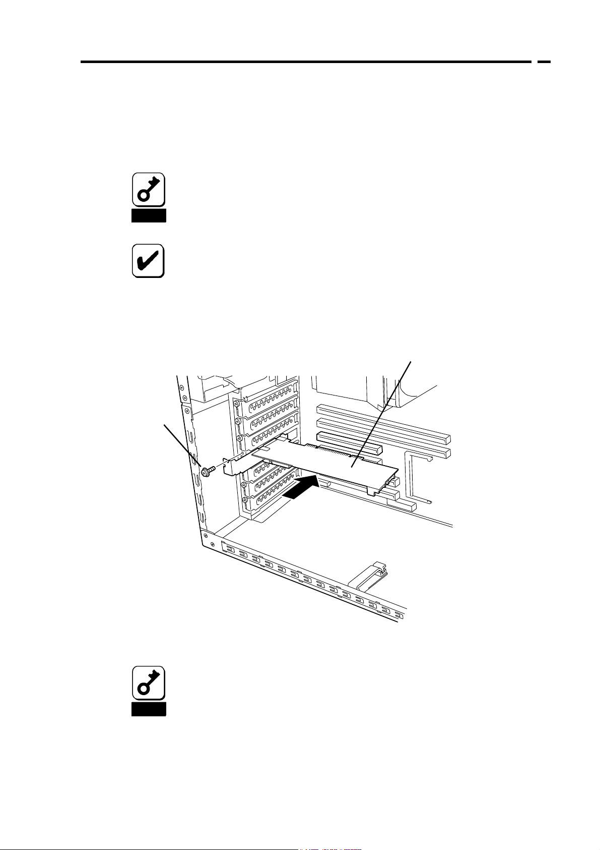
5-3. Installing the Disk Array Controller
1. Confirm the position of the PCI slot in which the disk array controller is installed
and remove the corresponding additional slot cover.
Save the removed additional slot cover carefully. The removed screw will
be used to install the card. Do not lose them.
The card does not support the PCI hot-plug feature. Before install or
Notice
Check
2. Insert the card into the PCI slot securely and fix it. To fix the card with screws, use
the screw removed when the additional slot cover is removed.
remove the card from the server, always turn off the server and pull out
the power cord from the receptacle.
Some limitation may be imposed to the installation on the PCI slot
depending on the type of the server. Before the installation, check the
limitation following the User’s Guide of the server.
63
This card (disk array controller)
Screw
3. To connect an additional battery to the card, install the battery in the same
procedure.
When the card cannot be inserted into the PCI slot well, pull out it once
and insert it again. Note that the cared may be damaged if excess force
is given to it.
Notice
For details of how to install the additional battery, refer to the User’s
Guide of the N8103-93 Battery Backup Unit (SATA).
Page 84

64
5-4. Connecting LED and SATA Cables
Connect the LED cable coming with the card to the HDD LED connector. For the
connection, see the figure below and the connection table. For the connection to the
motherboard, refer to the User’s Guide of the server. If it is hard to connect the LED cable,
pull out the card from the PCI slot once and connect the cable to the card.
Next, connect a SATA cable to the SATA connector on the card. The channel number of the
SATA cable should be the same as the channel number (port number) of the card.
LED cable
SATA cables
Port4
Port3
1 2 3 4
HDD LED connectors
Connect the black
cable to this pin.
Connect the red cable to this
pin. (This is not used for a
single-line LED cable.)
LED cable connection table
HDD LED
connector
Notice
Pin 1 Connected with red cable Not used
Pin 2 Connected with black cable Connected with black cable
Pin 3 Not used Not used
Pin 4 Not used Not used
Depending on the type of the server, the LED cable has two lines or only
a single line.
For the connection of the LED cable to the motherboard, refer to the
User’s Guide of the server.
To use the N8154-09F SATA2 HDD Cage, connect the SATA cable
coming with the cage to the card. For the detailed connection, refer to
the User’s Guide of the additional HDD cage.
LED cable (coming with server)
2-line cable 1-line cable
Page 85

65
5-5. Installing Additional HDD Cage
To install an additional HDD cage in the server, see the procedure described in the User’s
Guide coming with the additional HDD cage.
5-6. Connecting I2C Cable
To use the additional HDD cage, connect the card to the cage through the I2C cable
coming with the card. Connect the 3-pin connector (white) of the I2C cable to the I2C
connector on the card and the 4-pin connector (black) to the additional HDD cage. For the
mating connector on the additional HDD card, refer to the User’s Guide of the additional
HDD cage.
Without use of the additional HDD cage, the I2C cable may not be connected.
I2C connector
3-pin connector (white)
To additional HDD cage
I2C cable
The N8154-01F S-ATA HDD Cage also contains an I2C cable in its
package. However, it is unavailable for the card. Always use the I2C cable
coming with the card.
Notice
4-pin connector (black)
Page 86
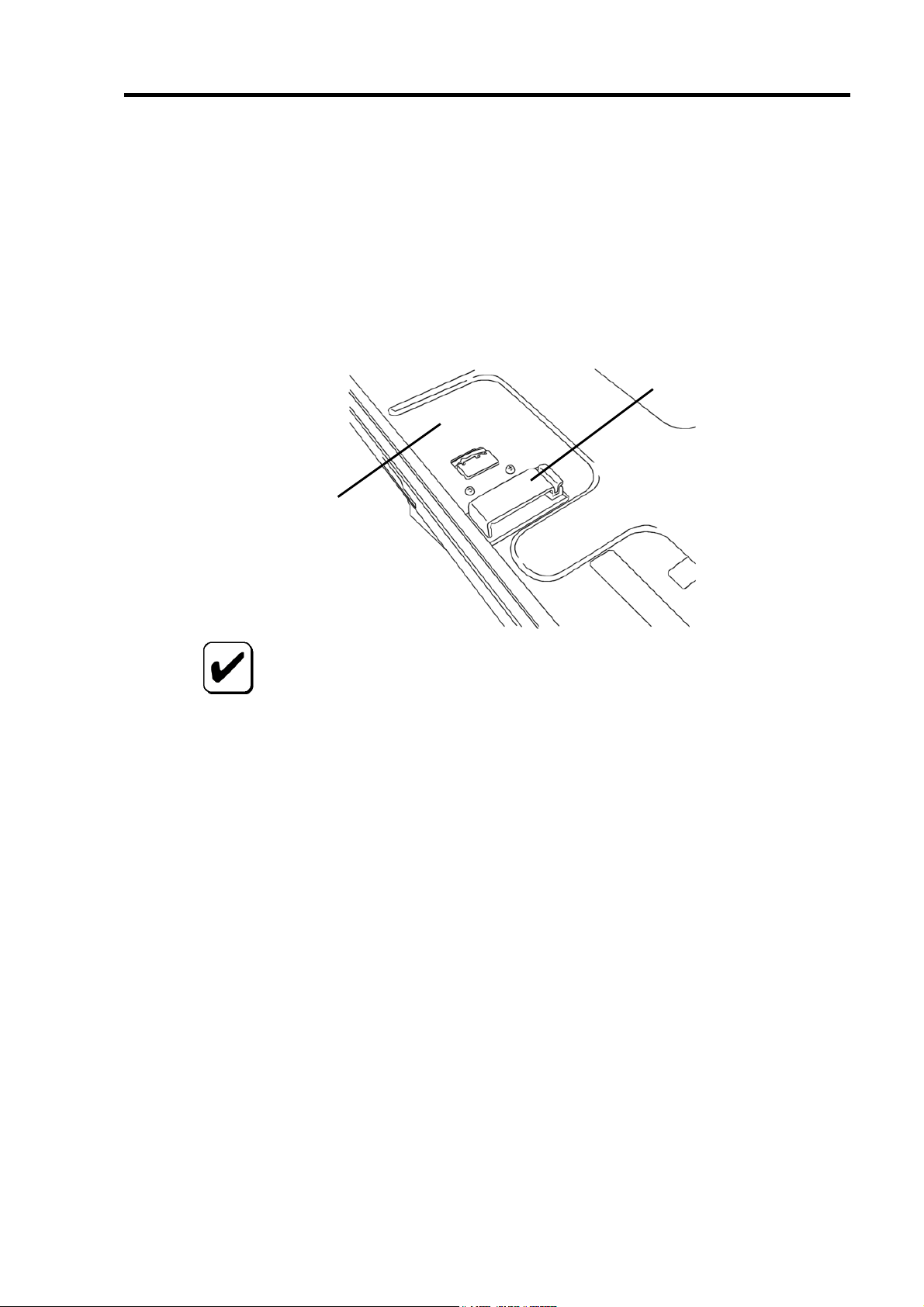
66
5-7. Forming Cables
To fix the SATA and I2C cables appropriately, form the cables in the following procedure.
1. Attachment of cable clamp
Attach the cable clamp coming with the card on the server. Attach the cable clamp
at an arbitrary position where cables can be fixed securely. Some servers do no
have any area available for the attachment of the cable clamp. If so, bundle
cables so that they may not be disordered.
Cable clamp
Bottom plate of
chassis of server
Before attaching the cable clamp on the server, wipe the area where the
cable clamp will be attached with dry cloth.
Some servers require their accessories to be used instead of the cable
Check
clamp coming with the card. For details, refer to the User’s Guides of the
servers.
Page 87

2. Cable forming
Release the lock of the cable clamp. Bundle the cables to fix them.
SATA cable
67
Cable clamp
I2C cable
After forming the SATA cable, make sure that the cable is not loose and
inserted to the mating connector straight.
Notice
Page 88

68
Chapter 2 RAID
This chapter describes the RAID features which the disk array controller supports.
1. Overview of RAID
1-1. What is RAID (Redundant Array of Inexpensive
Disks)?
RAID is an abbreviation for "Redundant Array of Inexpensive Disks." The RAID technology
allows more than one hard disk drive (HDD) to be handled collectively.
In actual, RAID can configure more than one HDD as a single array (logical drive) to
operate the HDDs effectively. This can bring higher performance than a single HDD of a
large capacity.
For the array (logical drive) configuration, the host computer recognizes more than one
HDD as if it were a single HDD. The host computer accesses to more than one HDD
configuring an array (logical drive) in parallel.
Some RAID levels can recover data from remaining data and parity by using rebuild if an
error occurs in an HDD. This can provide high reliability for the system.
Page 89
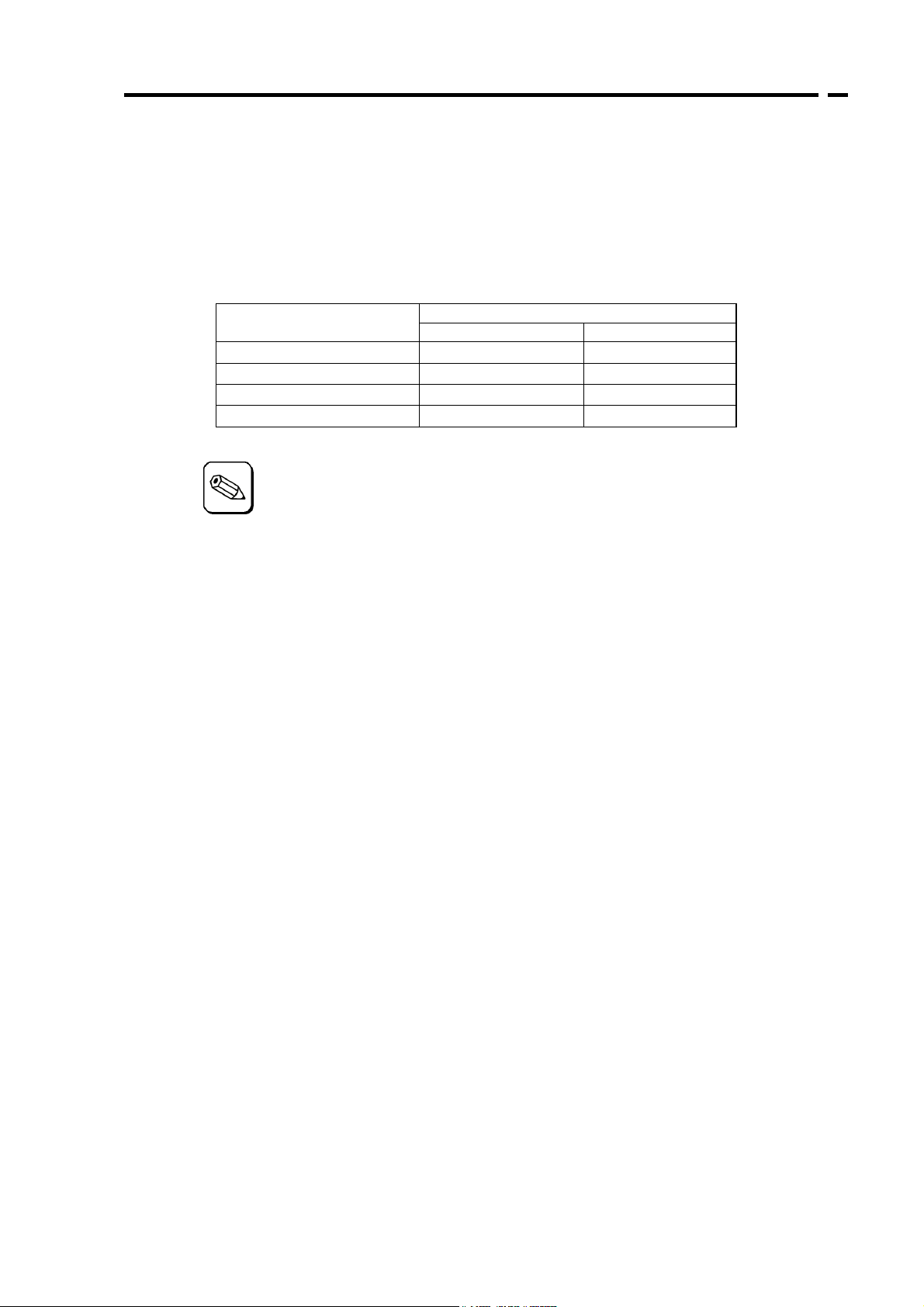
69
1-2. RAID Levels
The record mode enabling the RAID feature includes several levels. Among the levels, the
disk array controller supports the following levels; RAID 0, RAID 1, RAID 5, and RAID10.
The number of HDDs required to create a logical drive varies depending on the RAID level
as shown in the table below.
RAID level
RAID 0 1 4
RAID 1 2 2
RAID 5 3 4
RAID 10 4 4
Number of required HDDs
Min. Max.
For details of the RAID levels, see "2. RAID Levels" described later in this
chapter.
Tips
Page 90

70
1-3. Logical Drive
A logical drive is configured with a group of more than one HDD. It is recognized as a
physical drive by OS. Up to eight logical drives are permitted by the card when four HDDs
are installed in the server.
The figure below shows a sample configuration in which the disk array controller is
connected with four HDDs, three of which create a logical drive and the remaining HDD is
set to a single hot-spare disk.
Disk array controller
Logical drive 1
Channel 1
(Port 1)
LD 1-1
Channel 2
(Port 2)
LD 1-2
Channel 3
(Port 3)
LD 1-3
Channel 4
(Port 4)
Spare
LD x-x : HDDs assigned to
logical drive
Spare : Hot-spare disk
1-4. Parity
The parity means redundant data. A single set of redundant data is created from the data
saved in more than one HDD.
The created redundant data is used for data recovery when a HDD is defected.
1-5. Hot-Swap
The hot-swap enables a HDD to be removed (replaced) under system operation.
For the hot-swap with the card, an additional HDD cage must be connected
to the card.
Check
Page 91
71
1-6. Hot-Spare Disk
The hot-spare disk is prepared as an auxiliary HDD substituting for a defected HDD
included in a logical drive which is configured at a redundant RAID level. Detecting a HDD
fault, the system disconnects the HDD (or makes it offline) and starts rebuild using the
hot-spare disk. The hot-spare disk can be set in two types as listed in the table below.
Setting Feature
Global Spare
Dedicated Spare
To define a hot-spare disk, WebPAM, the management utility of the card,
must be installed.
Available as a hot-spare disk if a HDD in any logical drive is
defected. The disk of the type can accept media patrol.
Available as a hot-spare disk only if a HDD in the specified logical
disk is defected. The disk of the type can accept media patrol.
Check
Tips
For standby rebuild, or rebuild using hot-spare disks, see "Chapter 3
Features of Disk Array Controller."
"Free" disk
A "free" disk (unconfigured disk not assigned to a logical drive and hot-spare disk) can
substitute for defected HDD in the similar way as a global spare. In the configuration
including both hot-spare and "free" disks, the hot-spare disks are used preferentially.
However, "free" disks cannot be subject to media patrol. Thus it is recommended to define
"free" disks as hot-spare disks.
Page 92
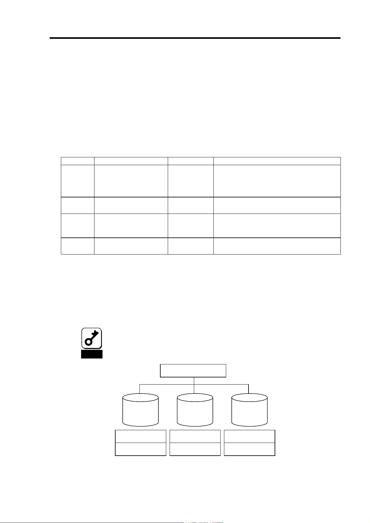
72
2. RAID Levels
This section details the RAID levels which the disk array controller can support.
2-1. Characteristics of RAID Levels
The table below lists the characteristics of the RAID levels.
Level Function Redundancy Characteristics
RAID0 Striping No Data read/write at the highest rate
Largest capacity
Capacity: (capacity of single HDD) ×
(number of HDDs)
RAID1 Mirroring Yes Two HDDs required
Capacity: capacity of single HDD
RAID5
RAID10
Striping of both data
and redundant data
Combination of striping
and mirroring
Yes Three or more HDDs required
Capacity: (capacity of single HDD) ×
((number of HDDs) - 1)
Yes Four HDDs required
Capacity: (capacity of single HDD) × 2
2-2. RAID0
In RAID 0, data to be recorded is distributed to HDDs. The mode is called "striping."
In the figure below, data is recorded in stripe 1 (disk1), stripe 2 (disk 2), and stripe 3 (disk
3)… in the order. Because RAID0 allows all HDDs to be accessed collectively, it can
provide the best disk access performance.
RAID 0 cannot have data redundancy. If a HDD is defected, the data saved
in the HDD cannot be recovered.
Notice
Disk array controller
Disk 1 Disk 2
Stripe 1
Stripe 4
Stripe 2
Stripe 5
Disk 3
Stri pe 3
Stri pe 6
Page 93

73
2-3. RAID1
In the RAID1 level, data saved in a HDD is recorded to another HDD without change. The
mode is called "mirroring."
When data is recorded to a single HDD, the same data is recorded to another HDD. If
either of the HDDs is defected, the other HDD containing the same data can substitute for
the defected HDD. Thus the system can continue to operate without interruption.
Disk array controller
Disk 1 Disk 2
Stri pe 1
Stri pe 2
Stripe 1
Stripe 2
2-4. RAID5
In RAID5, data is distributed to HDDs by striping and, at the same time, the parity
(redundant data) is distributed to the HDDs. This mode is called "striping with distributed
parity."
Each of stripe x, stripe x+1, and parity (x, x+1) created from stripe x and stripe x+1 is
recorded to a specific HDD. Accordingly, the total capacity assigned to the parity is just the
same as the capacity of a single HDD. If any one of the HDDs configuring a logical drive is
defected, data is still available without problems.
Disk array controller
Disk 1 Disk 2 Disk 3
Stripe 1
Stripe 4
Parity (5, 6)
Stripe 2
Parity (3, 4)
Stripe 5
Parity (1, 2)
Stripe 3
Stripe 6
Page 94

74
2-5. RAID10
Data is distributed to HDDs by striping and the stripes are recorded by mirroring. Therefore,
RAID10 can realize the disk access performance as high as RAID0 and the reliability as
high as RAID1 at a time.
Disk array controller
Disk 1 Disk 2
Stripe 1
Stripe 3
Stripe 5 Stripe 6 Str ipe 5
RAID0 RAID0
Stripe 2
Stripe 4
RAID1
Disk 3
Stripe 1
Stripe 3
Disk 4
Stri pe 2
Stri pe 4
Stri pe 6
Page 95

75
Chapter 3 Features of Disk Array
Controller
This chapter describes the features of the disk array controller.
1. Rebuild
If a HDD is defected, the rebuild feature can recover the data in the defected HDD. The
rebuild can be applied to redundant logical drives in the RAID1, RID5, or RAID10 level.
1-1. Manual Rebuild
The manual rebuild can be done by using WebPAM, the management utility of the disk
array controller. Select a HDD and start the rebuild manually.
For the detailed operation, refer to the online manual "Web-based Promise Array Manager
User’s Guide" saved in the "S-ATA Array Management Software" CD-ROM coming with the
card.
1-2. Auto Rebuild
The disk array controller can automatically start the rebuild without use of any utility such
as WebPAM.
The auto rebuild includes two types as follows:
Standby rebuild
Automatic rebuild by using hot-spare disks. In the configuration including
hot-spare disks, the rebuild is done automatically if a HDD assigned to a logical
drive is defected.
Hot-swap rebuild
Automatic rebuild by hot-swapping defected HDD.
Page 96

76
Notice
Note the following for the rebuild:
The HDD to be used for rebuild should have the same capacity, number
of revolutions, and standard as the defected HDD.
During rebuild, the processing rate is decreased due to much load.
During rebuild, do not shut down or reboot the server. If the server is
shut down by an unforeseen accident such as power interruption, turn on
the power again as soon as possible. The rebuild is automatically
restarted.
For the hot-swap rebuild, an additional HDD cage is required.
The interval from the removal of the defected HDD to the installation of a
substitute HDD should be 90 sec or longer.
If the hot-swap rebuild does not operate, perform the manual rebuild.
Page 97

77
2. Media Patrol
The media patrol gives the read & verify test in the entire area of HDDs. It can be done for
all HDDs assigned to logical drives and hot-spare disks.
The media patrol allows subsequent defects of HDDs to be detected and repaired.
Accordingly, routine media patrol is recommended as preventive maintenance. Routine
media patrol can be done by scheduling.
For HDDs configuring redundant logical drives in the RAID1, RAID5, or RAID10 level or
those assigned to hot-spare disks, error sectors detected during media patrol can be
repaired. For HDDs configuring non-redundant logical drives in the RAID0 level, error
sectors are registered to the bad sector list (BSL) to be managed.
If an access to a HDD being subject to media patrol occurs, the media patrol is interrupted
temporarily and continued from the interrupted point at the completion of the access. Thus,
the media patrol can hardly decrease the system performance.
Note the following for the media patrol:
In an environment of frequent HDD accesses, media patrol cannot be
advanced well. In such environment, it is recommended to use
Notice
synchronization for preventive maintenance instead of media patrol.
To enable media patrol, WebPAM must be installed.
For the detailed operation, refer to the online manual "Web-based
Promise Array Manager User’s Guide" saved in the "S-ATA Array
Management Software" CD-ROM coming with the card.
Page 98
78
3. Synchronization
The synchronization checks consistency among logical drives. It is available for redundant
logical drives in the RAID1, RAID5, or RAID10 level.
Similar to the media patrol, routine synchronization can be done by scheduling.
The synchronization can not only check consistency but also repair detected error sectors
in the same way as the media patrol. Accordingly, it can be used as preventive
maintenance.
Different from media patrol, the synchronization continues its operation at a certain rate if
targeting logical drives are accessed. Therefore, considerable load may be applied to the
system during synchronization to decrease in the processing rate. In an environment of
frequent accesses, preventive maintenance using synchronization is recommended
because media patrol cannot be advanced.
Note the following for the synchronization:
To perform synchronization, WebPAM must be installed.
For the detailed operation, refer to the online manual "Web-based
Notice
Promise Array Manager User’s Guide" saved in the "S-ATA Array
Management Software" CD-ROM coming with the card.
Page 99

79
4. Expansion
The expansion adds one or more HDDs to an existing logical drive to increase the capacity
of the logical drive.
Note the following for the expansion:
Before expansion, data backup and synchronization should always be
done.
Notice
During expansion, the processing rate is decreased due to much load.
Expansion is unavailable for a logical drive in the critical state. Before
the expansion, rebuild should be done to recover logical drive.
During expansion, do not shut down or reboot the server. If the server is
shut down by an unforeseen accident such as power interruption, turn on
the power again as soon as possible. After rebooting the system, the
expansion is automatically started.
For the expansion, WebPAM must be installed.
For the detailed operation, refer to the online manual "Web-based
Promise Array Manager User’s Guide" saved in the "S-ATA Array
Management Software" CD-ROM coming with the card.
Page 100
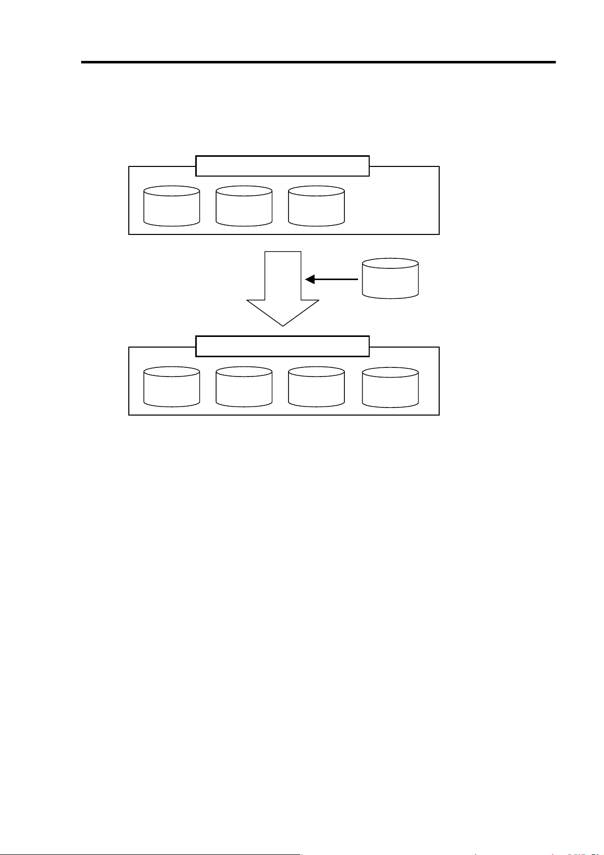
80
Ex: Expansion of logical drive in RAID5
The figure below shows an example of adding a single 80GB HDD to a RAID5 logical drive
configured with three 80GB HDDs.
Logical drive(RAID5
80GB 80GB 80GB
Logical drive(RAID5
80GB 80GB 80GB
)
[Before execution]
Capacity = 160GB
80GB
Expand
)
[After execution]
Capacity = 240GB
80GB
 Loading...