

Page 1
本書は製品とともに大切に保管してください
Keep this manual carefully.
N8103-102
増設バッテリ ユーザーズガイド
Additional DAC Battery User's Guide
• 製品をご使用になる前に必ず本書をお読みください。
本書は熟読の上、大切に保管してください。
• Make sure you read this manual before using the product.
After reading this manual carefully, store it in a safe place.
855-900502-011-A
Page 2

商標について
Microsoft とそのロゴおよび、Windows、MS、MS-DOSは米国 Microsoft 社の米国およびその他の国
における登録商標です。
PromiseTechnology, Inc.とそのロゴおよび、SuperTrak、SuperBuild
Array Management(WebPAM)は、米国 Promise 社の登録商標です。
TM
Utility、Web-based Promise
Trademarks
Microsoft, its logo, Windows, Windows Server and MS-DOS are worldwide registered trademarks of
Microsoft Corporation of the U.S.A.
Promise Technology, Inc., its logo, SuperTrak, SuperBuild
Manager (WebPAM) are registered trademarks of Promise Technology Inc. of the U.S.A.
All company names and product names mentioned herein are trademarks or registered trademarks
of their respective companies.
TM
Utility, and Web-based Promise Array
ご注意
(1) 本書の内容の一部または全部を無断転載することは禁止されています。
(2) 本書の内容に関しては将来予告なしに変更することがあります。
(3) NECの許可なく複製・改変などを行うことはできません。
(4) 本書は内容について万全を期して作成いたしましたが、万一ご不審な点や誤り、記載もれなど
お気づきのことがありましたら、お買い求めの販売店にご連絡ください。
(5) 運用した結果の影響については(4)項にかかわらず責任を負いかねますのでご了承ください。
(6) 落丁、乱丁本はお取り替えいたします。
Notes:
(1) No part of this manual may be reproduced in any form without the prior written permission of
NEC Corporation.
(2) The contents of this manual may be revised without prior notice.
(3) The contents of this manual shall not be copied or altered without the prior written permission of
NEC Corporation.
(4) All efforts have been made to ensure the accuracy of all information in this manual. If you
notice any part unclear, incorrect, or omitted in this manual, contact the sales agent where you
purchased this product.
(5) NEC assumes no liability arising from the use of this product, nor any liability for incidental or
consequential damages arising from the use of this manual regardless of Item (4).
(6) If you find any missing pages or pages out of order in this manual, please contact your dealer
for a replacement.
Page 3

まえがき
Preface
このたびは、N8103-102 増設バッテリ(以降「本製品」と呼ぶ)をお買い上げいただきまこ
とにありがとうございます。本書は、本製品を正しく、安全に設置・使用するための手引
きです。本製品を取り扱う前に必ずお読みください。また、本製品を使用する上でわから
ないこと、不具合が起きたときにもぜひご利用ください。本書は、必要な時にすぐに参照
できるように必ずお手元に保管してください。
本製品を取り付けるN8103-101 ディスクアレイコントローラ(SATA2)の取り扱いについて
は、N8103-101 ディスクアレイコントローラ(SATA2)添付のユーザーズガイドをご覧くだ
さい。
また、本製品を取り扱う前に「使用上のご注意」を必ずお読みください。
なお、本書は和英併記となっております。日本語での説明は i ページから 20 ページを、英
語での説明は i ページから xviii ページおよび、21 ページから 38 ページを参照してくださ
い。
Congratulations for your purchase of the N8103-102 Additional DAC Battery (called BBU
hereafter). The User’s Guide describes how to install and use the BBU correctly and safely.
Read the guide thoroughly before handling it. In addition, refer to this manual when you
want to know how to use it or some malfunction occurs. Alw ays keep the m anu al at hand
so that you can see it as soon as possible if necessary.
For the N8103-101 Disk Array Controller (SATA2) to which the BBU is connected, refer to
the User’s Guide coming with the disk array controller.
Read "Notes on Use" carefully before handling the BBU.
This User's Guide is written in both Japanese and English. For Japanese, refer to pages i
to 20. For English, refer to pages i to xviii and 21 to 38.
Page 4
ii
このユーザーズガイドは、必要なときすぐに参照できるよう、お手元に置いておくようにしてください。
「使用上のご注意」を必ずお読みください。
Keep this User's Guide at hand for quick reference at anytime necessary.
Be sure to read this section carefully.
使用上のご注意 〜必ずお読みください〜
NOTES ON USE
本製品を安全に正しくご使用になるために必要な情報が記載されています。
The following includes information necessary for proper and safe operation of the product.
- Always read the Notes -
安全に関わる表示について
SAFETY INDICATIONS
本書では、安全にお使いいただくためにいろいろな絵表示をしています。表示を無視し、
誤った取り扱いをすることによって生じる内容を次のように区分しています。内容をよく
理解してから本文をお読みください。
In the User’s Guide, "WARNING" or "CAUTION" is used to indicate a degree of danger.
These terms are defined as follows:
WARNING
人が死亡する、または重傷を負うおそれがあることを示します。
Indicates the presence of a hazard that may result in death or serious
personal injury.
CAUTION
火傷やけがなどを負うおそれや物的損害を負うおそれがあることを示しま
す。
Indicates the presence of a hazard that may cause minor personal injury,
including burns, or property damage.
Page 5
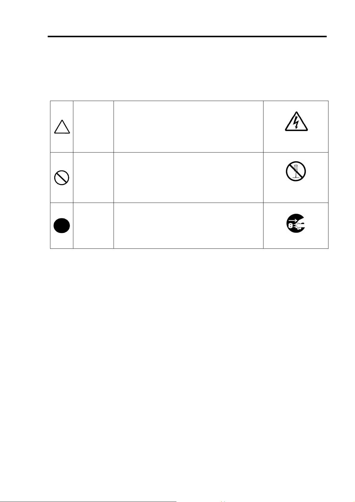
危険に対する注意・表示は次の3種類の記号を使って表しています。それぞれの記号は次
のような意味を持つものとして定義されています。
Precautions against hazards are presented with the following symbols. The individual
symbols are defined as follows:
(例) (Example)
この記号は危険が発生するおそれがあることを表し
注意の喚起
Attention
行為の禁止
Prohibited
Action
行為の強制
Mandatory
Action
ます。記号の中の絵表示は危険の内容を図案化したも
のです。
This symbol indicates the presence of a hazard.
An image in the symbol illustrates the hazard type.
この記号は行為の禁止を表します。記号の中や近くの
絵表示は、してはならない行為の内容を図案化したも
のです。
This symbol indicates prohibited actions. An image
in the symbol illustrates a particular prohibited action.
この記号は行為の強制を表します。記号の中の絵表示
は、しなければならない行為の内容を図案化したもの
です。危険を避けるためにはこの行為が必要です。
This symbol indicates mandatory actions. An image
in the symbol illustrates a mandatory action to avoid
a particular hazard.
(感電注意)
Precauti o n against
electric shock
(例) (Example)
(分解禁止)
Prohibit i o n of
disassembly
(例) (Example)
(プラグを抜け)
Unplug the power cord!
iii
Page 6
iv
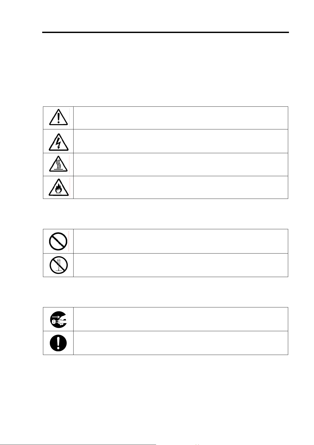
本書で使用する記号とその内容 Symbols Used in This Manual and Warning Labels
注意の喚起
Attentions
特定しない一般的な注意・警告を示します。
Indicates a general notice or warning that cannot be specifically identified.
感電のおそれがあることを示します。
Indicates that improper use may cause an electric shock.
高温による障害を負うおそれがあることを示します。
Indicates that improper use may cause personal injury.
発煙または発火のおそれがあることを示します。
Indicates that improper use may cause fumes or fire.
行為の禁止
Prohibited Actions
特定しない一般的な禁止を示します。
Indicates a general prohibited action that cannot be specifically identified.
分解・修理しないでください。感電や火災のおそれがあります。
Do not disassemble, repair, or modify the server. Otherwise, an electric shock or fire
may be caused.
行為の強制
Mandatory Action
電源コードをコンセントから抜いてください。火災や感電のおそれがあります。
Unplug the power cord of the server. Otherwise, an electric shock or fire may be
caused.
特定しない一般的な使用者の行為を指示します。説明に従った操作をしてください。
Indicates a mandatory action that cannot be specifically identified. Make sure to
follow the instruction.
Page 7
v
安全上のご注意 Safety Indications
本製品を安全にお使いいただくために、ここで説明する注意事項をよく読んでご理解して
いただき、安全にご活用ください。記号の説明については巻頭の『安全にかかわる表示に
ついて』の説明を参照してください。
This section provides notes on using your product safely. Read this section carefully to
ensure proper and safe use of the product. For symbols, see "SAFETY INDICATIONS"
provided earlier.
<全般的な注意事項>
General
人命に関わる業務や高度な信頼性を必要とする業務には使用しない
Do not use the product in life-critical applications or applications requiring
high reliability.
本製品は、医療機器、原子力設備や機器、航空宇宙機器、輸送設備や機器など人命
に関わる設備や機器、および高度な信頼性を必要とする設備や機器などへの組み込
みや制御等の使用は意図されておりません。これら設備や機器、制御システムなど
に本製品を使用され、人身事故、財産損害などが生じても、当社はいかなる責任も
負いかねます。
The product is not intended for integration with or control of facilities or eq ui pm ent
that may affect human life or that require a high degree of reliability, such as
medical equipment, nuclear power facilities or instruments, aerospace instruments,
transportation facilities or instruments. NEC does not assume any liability for
accidents resulting in injury or death, or for any damages to property that may occur
as a result of using the product in such facilities, equipment, or cont rol sy st ems.
煙や異臭・異音がしたまま使用しない
Do not use the server if any smoke, odor, or noise is present.
万一、煙、異臭、異音などが生じた場合は、ただちに本体装置の電源をOFFにして
電源コードをACコンセントから抜いてください。その後、お買い求めの販売店また
は保守サービス会社にご連絡ください。そのまま使用すると火災の原因となります。
If smoke, odor, or noise is present, immediately turn off the server and disconnect
the power plug from the AC outlet, then contact your service representative. Using
the server in such conditions may cause a fire.
針金や金属片を差し込まない
Keep needles or metal objects away from the server.
通気孔やカートリッジ挿入口から金属片や針金などの異物を差し込まないでくださ
い。感電するおそれがあります。
Do not insert needles or metal objects into ventilation holes or cartridge slot of the
server. Doing so may cause an electric shock.
WARNING
Page 8
vi
CAUTION
装置内に水や異物を入れない
Keep water or foreign matter away from the server.
装置内に水などの液体、ピンやクリップなどの異物を入れないでください。火災や
感電、故障の原因となります。もし入ってしまったときは、すぐに本体装置の電源
をOFFにして電源コードをACコンセントから抜いてください。分解しないで販売店
または保守サービス会社に連絡してください。
Do not let any form of liquid (water etc.) or foreign matter (e.g., pins or paper clips)
enter the server. Failure to follow this warning may cause an electric shock, a fire, or
a failure of the server. When such things accidentally enter the server, immediately
turn off the power and disconnect the power plug from the AC outlet. Do not
disassemble the server. Contact your service representative.
Page 9
<電源・電源コードに関する注意事項>
Power Supply and Power Cord Use
vii
電源がONのまま取り付け・取り外しをしない
Disconnect the power cord(s) before installing or removing the product
in/from the server.
本体装置への取り付け・取り外しの際や、周辺機器との接続の際は必ず主電源に接
続している電源コードをACコンセントから抜いてください。電源コードがACコンセ
ントに接続されたまま取り付け・取り外しや接続をすると感電するおそれがありま
す。
Make sure to power off the server and disconnect the power cord(s) from a power
outlet before installing/removing the product in/from the server, or connecting with
the peripheral devices. All voltage is removed only when the power cords are
unplugged.
破損したケーブルを使用しない
Do not use any damaged cable.
ケーブルを接続する前にコネクタが破損していたり、コネクタピンが曲がっていた
り、汚れたりしていないことを確認してください。破損や曲がっているコネクタお
よび汚れたコネクタを使用するとショートにより火災を引き起こすおそれがありま
す。
Make sure the cable condition before connection. Using the damaged connector,
bent connector pin, or dirty connector may cause a fire due to short-circuit.
ぬれた手で電源コードをもたない
Do not hold the power plug with a wet hand.
本製品の取り付け・取り外しの場合は、ぬれた手で本体装置の電源コードの抜き差
しをしないでください。感電するおそれがあります。
Do not disconnect/connect the plug while your hands are wet. Failure to follow this
warning may cause an electric shock.
電源コードのケーブル部を持って引き抜かない
Do not pull the cable when disconnecting the power cord.
本体装置の電源コードの抜き差しは、ケーブル部を持って引っ張らないでください。
ケーブルが傷み、感電や火災の原因となります。
When disconnecting the power cord from the server, hold the plug and pull it straight
out. Pulling the cord out by the cable portion could damage the cable to result in an
electrical shock hazard or a fire.
CAUTION
Page 10
viii
<設置・移動・保管・接続に関する注意事項>
Installation, Relocation, Storage, and Connection
CAUTION
プラグを差し込んだままインタフェースケーブルの取り付けや取り外しをしない
Do not connect any interface cable with the power cord of the server plugged
to a power source.
インタフェースケーブルの取り付け/取り外しは本体装置の電源コードをコンセン
トから抜いて行ってください。たとえ電源をOFFにしても電源コードを接続したま
まケーブルやコネクタに触ると感電したり、ショートによる火災を起こしたりする
ことがあります。
Make sure to power off the server and unplug the power cord from a power outlet
before connecting/disconnecting any interface cable to/from the server. If the
server is off-powered but its power cord is plugged to a power source, touching a
cable or connector may cause an electric shock or a fire resulted from a short
circuit.
指定以外のインタフェースケーブルを使用しない
Do not use any unauthorized interface cable.
インタフェースケーブルは、NECが指定するものを使用し、接続する装置やコネク
タを確認した上で接続してください。指定以外のケーブルを使用したり、接続先を
誤ったりすると、ショートにより火災を起こすことがあります。
また、インタフェースケーブルの取り扱いや接続について次の注意をお守りくださ
い。
ケーブルを踏まない。
ケーブルの上にものを載せない。
ケーブルの接続がゆるんだまま使用しない。
破損したケーブルを使用しない。
破損したケーブルコネクタを使用しない。
ネジ止めなどのロックを確実に行ってください。
Use only interface cables authorized by NEC and locate a proper device and
connector before connecting a cable. Using an unauthorized cable or connecting a
cable to an improper destination may cause a short circuit, resulting in a fire.
Also, observe the following notes on using and connecting an interface cable.
Do not step on the cable.
Do not place any object on the cable.
Do not use the server with loose cable connections.
Do not use any damaged cable connector.
Make sure the cable is securely locked with screw.
Page 11
ix
腐食性ガスの存在する環境で使用または保管しない
Do not use or store the product in the place where corrosive gases exist.
腐食性ガス(二酸化硫黄、硫化水素、二酸化窒素、塩素、アンモニア、オゾンなど)
の存在する環境に設置し、使用しないでください。
また、ほこりや空気中に腐食を促進する成分(塩化ナトリウムや硫黄など)や導電
性の金属などが含まれている環境へも設置しないでください。装置内部のプリント
板が腐食し、故障および発煙・発火の原因となるおそれがあります。もしご使用の
環境で上記の疑いがある場合は、販売店または保守サービス会社にご相談ください。
Make sure not to locate or use the server in the place where corrosive gases (sulfur
dioxide, hydrogen sulfide, nitrogen dioxide, chlorine, ammonia, ozone, etc) exist.
Also, do not install it in the environment where the air (or dust) includes components
accelerating corrosion (ex. sulfur, sodium chloride) or conductive metals. There is a
risk of a fire due to corrosion and shorts of an internal printed board.
Consult with your service representative for the location appropriate to the server.
高温注意
Avoid installation in extreme temperature conditions.
本体装置の電源をOFFにした直後は、内蔵型のハードディスクドライブなどをはじ
め装置内の部品が高温になっています。十分に冷めたことを確認してから取り付け/
取り外しを行ってください。
Immediately after the server is powered off, its internal components such as hard
disk drives are very hot. Leave the server until its internal components fully cool
down before installing/removing any component.
CAUTION
Page 12
x
<お手入れに関する注意事項>
Cleaning and Working wit
h the Product
自分で分解・修理・改造はしない
Do not disassemble, repair, or alter the server.
本製品の分解や、修理・改造は絶対にしないでください。装置が正常に動作しなく
なるばかりでなく、感電や火災の危険があります。
Never attempt to disassemble, repair, or alter the product on any occasion. Failure
to follow this instruction may cause an electric shock or fire as well as malfunctions
of the product.
プラグを差し込んだまま取り扱わない
Disconnect the power plug before accessing inside the server.
お手入れは、本体装置の電源をOFFにして、電源コードをACコンセントから抜いて
ください。たとえ電源をOFFにしても、電源コードを接続したまま装置内の部品に
触ると感電するおそれがあります。
Make sure to power off the server and disconnect the power plug from a AC outlet
before accessing inside the server. Touching any internal device of the server with
its power cord connected to a power source may cause an electric shock even if the
server is off-powered.
WARNING
中途半端に取り付けない
Make sure to complete installation.
DCケーブルやインタフェースケーブルは確実に取り付けてください。中途半端に取
り付けると接触不良を起こし、発煙や発火の原因となるおそれがあります。
Always connect the DC cable and/or interface cable firmly. An incompletely
connected cable may cause a contact failure, resulting in smoking or fire.
CAUTION
Page 13
<運用中の注意事項>
During Operation
xi
雷がなったら触らない
Avoid contact with the server during thunderstorms.
雷が鳴りだしたら、本製品内蔵の本体装置には、触れないでください。感電するお
それがあります。
Disconnect the power plug from the outlet when a thunderstorm is approaching.
If it starts thundering before you disconnect the power plug, do not touch any part of
the server containing the product. Failure to follow this warning may cause an
electric shock.
ペットを近づけない
Keep animals away from the server.
本製品が内蔵された本体装置にペットなどの生き物を近づけないでください。排泄
物や体毛が装置内部に入って火災や感電の原因となります。
Keep animals away from the server containing the product.
Pet's discharges or fur may enter the server and cause a fire or electric shock.
近くで携帯電話やPHSを使用しない
Do not use a cellular phone or a pager around the server.
本製品が内蔵された本体装置のそばでは、携帯電話やPHS、ポケットベルの電源を
OFFにしてください。電波による誤動作の原因となります。
Turn off the cellular phone or pager near the server containing the product. Radio
interference may cause malfunctions of the server.
CAUTION
Page 14
xii
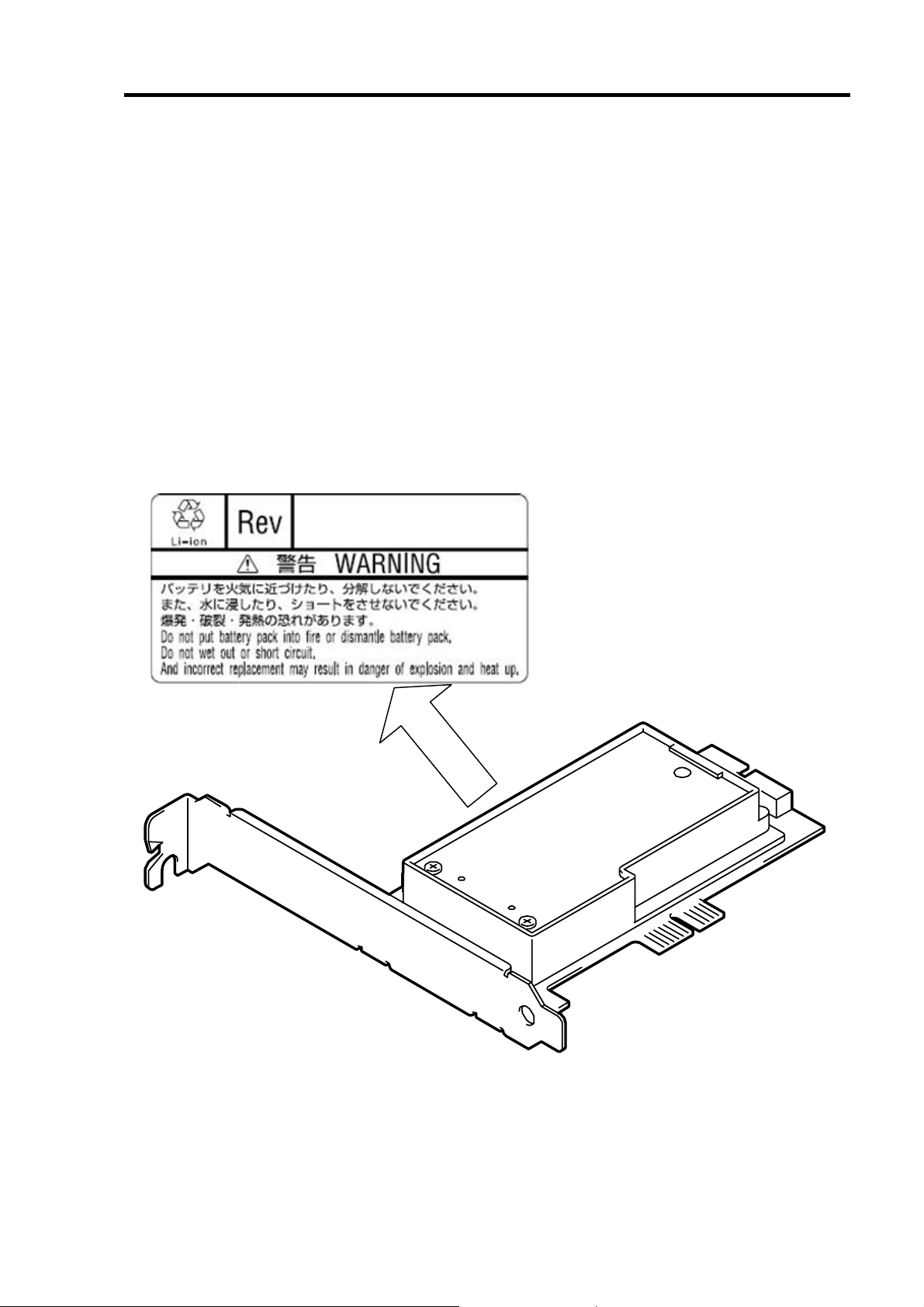
警告ラベルについて Warning Labels
本製品には警告ラベルが貼り付けられています。これは本製品を操作する際に考えられる
危険性を常にお客様に意識していただくためのものです(ラベルをはがしたり、汚したり
しないでください)。もしこのラベルが貼り付けられていない、はがれかかっている、汚れ
ているなどして判読できないときはご購入された販売店にご連絡ください。
The warning label is attached to the product with possible danger or their vicinity in your
product to inform the user that a hazardous situation may arise when operating the product.
(Do not intentionally remove or damage any of the labels.)
If you find any labels totally/partially removed or illegible due to damage, contact your sales
representative.
Page 15

xiii
使用上のご注意 〜装置を正しく動作させるために〜
Notes on Use - for correct operation of BBU -
本製品を使用するときに注意していただきたいことを次に示します。これらの注意を無視
して、本製品を使用した場合、資産(データやその他の装置)が破壊されるおそれがあります
ので必ずお守りください。
本製品は N8103-101 ディスクアレイコントローラ(SATA2)専用の増設バッテリで
す。その他のディスクアレイコントローラには接続できません。
本製品は大変デリケートな電子装置です。本製品を取り扱う前に、本体装置の金
属フレーム部分などに触れて身体の静電気を逃がしてください。
本製品を落としたり、ぶつけたりしないでください。
本製品のリサイクルと廃棄に関しては、本章の「リサイクル・廃棄について」を
参照して下さい。
Note the following when you use the BBU. If you ignore the notes, your assets (including
important data and/or other devices) may be damaged.
The BBU is an additional battery exclusively used for the N8103-101 Disk Array
Controller (SATA 2). The BBU cannot be connected to any other disk array
controllers.
The BBU is an extremely sensitive electronic device. First make your body
contact with metallic frame of the server to discharge static electricity from your
body before handling the BBU.
Do not d rop the BBU. Do no t mak e th e BBU hit aga inst other objects.
For the recycle and disposal of the BBU, see "Recycle and Disposal" in this
chapter.
Page 16
xiv
本書について This Manual
本書は、Windowsなどのオペレーティングシステムやキーボード、マウスといった一般的
な入出力装置などの基本的な取り扱いについて十分な知識を持ったユーザを対象として記
載されています。
The guide is intended for persons who are familiar with operating systems including
Windows and fundamental operations of general-purpose I/O devices including the
keyboard and mouse.
<本書の記号について>
Text Conventions
本書の中には安全に関わる注意記号の他に次の3種類の記号を使用しています。それぞれ
の記号は次のような意味をもつものとして定義されています。
The following conventions are used throughout this User's Guide. For safety symbols, see
"SAFETY INDICATIONS" provided earlier.
装置を取り扱う上で、守らなければいけないことや、特に注意すべき
点を示します。
Notice
Check
Tips
Items to be observed or points to be noted when operating the
product.
装置を取り扱う上で、確認をしておく必要がある点を示します。
Items to be checked when operating the product
知っておくと役に立つ情報や便利なことを示します。
Information useful or convenient for you
Page 17

xv
梱包箱の中身について In the Package
梱包箱の中には本製品以外に色々な添付品が同梱されています。本製品に添付の構成品表
を参照し、全ての添付品が揃っていることを確認してください。万一、足りないものや損
傷しているものがあった場合には、本製品をご購入された販売店にご連絡ください。
The carton contains various accessories, as well as the product itself. See the packing list
to make sure that you have everything and that individual components are not damaged. If
you find any component missing or damaged, contact your sales agent.
輸送について Transportation
本製品を輸送する際は、「第 1 章 概要」を参考に本体装置から本製品を取り出し、本製品
とすべての添付品を購入時の梱包箱に入れてください。
To transport the BBU, remove it from the server following "Chapter 1 Overview" and put the
BBU and all the accessories in the package used for the delivery.
Page 18
xvi
第三者への譲渡について Transfer to T hird Party
本製品を第三者に譲渡(または売却)する時には、必ず本書を含む全ての添付品をあわせ
て譲渡(または売却)してください。
Make sure to provide this manual along with the product to a third party.
Notice
HDD内のデータについて
譲渡する装置内に搭載されているHDDに保存されている大切なデータ(例えば顧客
情報や企業の経理情報など)が第三者へ漏洩することの無いようにお客様の責任に
おいて確実に処分してください。
WindowsやLinuxなどのオペレーティングシステムの「ゴミ箱を空にする」操作や
オペレーティングシステムの「フォーマット」コマンドでは見た目は消去されたよ
うに見えますが、実際のデータはHDDに書き込まれたままの状態にあります。完全
に消去されていないデータは、特殊なソフトウェアにより復元され、予期せぬ用途
に転用されるおそれがあります。
このようなトラブルを回避するために市販の消去用ソフトウェア(有償)またはサー
ビス(有償)を利用し、確実にデータを処分することを強くお勧めします。データの
消去についての詳細は、お買い求めの販売店または保守サービス会社にお問い合わ
せください。
なお、データの処分をしないまま、譲渡(または売却)し、大切なデータが漏洩さ
れた場合、その責任は負いかねます。
About data on the hard disk
Be sure to take appropriate measures not to leak important data (e.g., customers'
information or companies' management information) on the removed hard disk to
any third parties.
Data seems to be erased when you empty "Recycle Bin" of Windows or execute
the "format" command of the operating system. However, the actual data remains
written on the hard disk. Data not erased completely may be restored by special
software and used for unexpected purposes.
It is strongly recommended that the software or service (both available at stores)
for data erasure should be used in order to avoid the trouble explained above. For
details on data erasure, ask your sales representative.
NEC assumes no liability for data leakage if the product is transferred to third party
without erasing the data.
Page 19

xvii
製品寿命について Life of BBU
本製品にはバックアップ用のバッテリが付いています。バッテリの寿命は使用環境や運用
条件により異なりますが、約 2 年間となっております。
本製品の設置から約2年後(設置時期は本体装置および本製品に貼り付けのバッテリラベル
に記載)を目安に交換してください。交換については、本製品をご購入された販売店もしく
はご契約されている NEC 保守サービス会社へご相談ください。
The BBU is equipped with a backup battery. The life of the battery is about 2 years while it
varies depending on the use environment and operating conditions.
Replace the battery with a new one after about two years from the installation of the BBU
(the installation time can be known by the battery label put on the server and the BBU).
Contact your service representative for the replacement
保守用部品について Maintenance Parts
本製品の保守用部品の保有期間は、製造打ち切り後 5 年です。
The holding period of maintenance parts of the BBU is five years from the truncation of
manufacturing.
Page 20

xviii
リサイクル・廃棄について Recycle and Disposal
本製品のバッテリパックにはリチウムイオンバッテリが搭載されており、リサイクルが可
能です。貴重な資源を再利用するため、本製品をご購入された販売店もしくはご契約され
ている NEC 保守サービス会社までお問い合わせいただくか、最寄りのリサイクル協力店
にお持ちください。バッテリパックの取り外し方法は、「第 3 章 運用・保守」の「4. バッ
テリパックの交換手順」従ってください。
その他部材の破棄については、各自治体の廃棄ルールに従って分別廃棄してください。詳
しくは各自治体にお問い合わせいただくか、本製品をご購入された販売店もしくはご契約
されている NEC 保守サービス会社にご相談ください。
バッテリパックは「第 3 章 運用・保守」を参照して取り扱いに十分注意してください。
The battery pack of the BBU is equipped with lithium ion battery which is recyclable. To
enable such valuable resources to be reused, contact your service represent ative or bring
it to the nearest recycle agent. For the removal of the BBU, see "4. Battery Pack
Replacement Procedure" in "Chapter 3 Operation and Maintenance".
Dispose of other devices following the regulation of the local government. For details,
contact the local government or your service representative.
Take sufficient note on the handling of the battery pack following "Chapter 3 Operation and
Maintenance".
Notice
ハードディスクドライブやバックアップデータカートリッジ、フロッ
ピーディスク、その他書き込み可能なメディア(CD-R/CD-RW)に保存
されているデータは、第三者によって復元や再生、再利用されないよ
うお客様の責任において確実に処分してから廃棄してください。個人
のプライバシーや企業の機密情報を保護するために十分に配慮をして
ください。
Dispose of hard disk drives, backup data cartridges, floppy disks and
other writable media (including CD-R/CD-RW) after erasing the data
saved in the media securely on your own responsibility so that the
data may not be restored, replayed, and/or reused by third parties.
Take special care for protecting individual privacy and corporate
secret.
Page 21

目 次
まえがき Preface ......................................................................................................................... i
使用上のご注意 〜必ずお読みください
〜 NOTES ON USE - Always read the Notes - ..................... .. .. .. .. .. ............................... ii
本書で使用する記号とその内容 Symbols Used in This Manual and Warning Labels....... .. ....... iv
安全上のご注意 Safety Indications.............................................................................................. v
警告ラベルについて Warning Labels .........................................................................................xii
使用上のご注意 〜装置を正しく動作させるために
〜 Notes on Use - for correct operation of BBU -......................................................................xiii
本書について This Manual........................................................................................................xiv
梱包箱の中身について In the Package ..................................................................................... xv
輸送について Transportation..................................................................................................... xv
第三者への譲渡について Transfer to Third Party......................................................................xvi
製品寿命について Life of BBU .................................................................................................xvii
保守用部品について Maintenance Parts..................................................................................xvii
リサイクル・廃棄について Recycle and Disposal. .. .. .......................... .. .. ......................... .. .. .. xviii
目 次........................................................................................................................................xix
xix
第 1 章 概要...... ................................................. ..................................................................1
1. 本製品の特徴...............................................................................................................................1
2. 仕様.............................................................................................................................................2
3. 取り付け作業の流れ....................................................................................................................3
4. 梱包箱の中身を確認する.............................................................................................................4
5. 各部の名称と機能........................................................................................................................5
6. 注意事項......................................................................................................................................7
6-1. 取り付け時の注意事項.........................................................................................................7
6-2. 運用時の注意事項................................................................................................................7
第 2 章 本製品の取り付け ............................................. ................................................. .....9
1. 取り付け手順...............................................................................................................................9
1-1. PCI スロットの選択..............................................................................................................9
1-2. ブラケットの選択・取り付け ............................................................................................10
1-3. バッテリラベルの貼り付け................................................................................................10
1-4. サイドカバーの取り外し ................................................................................................... 11
1-5. 本製品の取り付け.............................................................................................................. 11
2. ユーティリティからの確認 .......................................................................................................13
第 3 章 運用・保守............................................................................................................15
1. 保守サービス.............................................................................................................................15
2. 予防保守....................................................................................................................................15
2-1. 本製品の予防保守..............................................................................................................15
2-2. バッテリパックの寿命.......................................................................................................15
3. バッテリパックの交換手順 .......................................................................................................16
Page 22

xx
Contents
Chapter 1 Overview....................................... ....................................................................21
1. Characteristics of BBU...............................................................................................................21
2. Specification...............................................................................................................................22
3. Installation Flow .........................................................................................................................22
4. Checking Contents in Package..................................................................................................23
5. Names and Functions of Sections..............................................................................................24
6. Notes..........................................................................................................................................26
6-1. Notes on Installation...........................................................................................................26
6-2. Notes on Operation ............................. .. .. .. .. .. .. .. .......................... .. .. .. .. ......................... ......26
Chapter 2 Installing BBU....................................................................................................27
1. Installation Procedure.................................................................................................................27
1-1. Selecting PCI Slot...............................................................................................................27
1-2. Selecting and Installing Bracket..........................................................................................28
1-3. Putting Battery Label ..........................................................................................................29
1-4. Removing Side Cover on Server ........................................................................................29
1-5. Installing BBU in Server.............. .. .. .......................... .. ......................... ......................... ......30
2. Checking by Utility......................................................................................................................32
Chapter 3 Operation and Maintenance..............................................................................33
1. Maintenance Service..................................................................................................................33
2. Preventive Maintenance.............................................................................................................33
2-1. Preventive Maintenance of BBU.........................................................................................33
2-2. Life of Battery Pack....................... .. ... .. .. .. .. .. ......................... .. ... .. .. ......................... .. .. ........33
3. Battery Pack Replacement Procedure .......................................................................................34
Page 23

第 1 章 概要
N8103-102 増設バッテリ(以降「本製品」と呼ぶ)を初めてお使いになる場合は、この章か
らお読みください。
ここでは、本製品の特徴、構成およびバッテリ増設作業の概要について説明します。
1. 本製品の特徴
本製品は N8103-101 ディスクアレイコントローラ(SATA2)(以降「ディスクアレイコント
ローラ」と呼ぶ)専用の増設バッテリです。
本製品をディスクアレイコントローラに実装する事で、電源瞬断などの不慮の事故による
データ損失の危険(Write Back 運用時)を回避することができます。
ディスクアレイコントローラの SDRAM内のデータを長時間バックアップ(最大
72 時間)
Write Back 運用時の信頼性向上
再利用可能なリチウムイオンバッテリを採用
PCI ブラケットの取り付け位置を変更することで、PCI/PCI-X スロットと
PCI-Express スロットのどちらのスロットにも実装可能
Page 24

2
2. 仕様
項 目 仕 様 備 考
最大データバックアップ時間 72 時間 満充電時
フルハイト PCI ブラ
ケット使用時
ロープロファイル PCI
ブラケット使用時
質量 約 0.10(kg)
動作電圧 3.7(V)〜 正常時
消費電力
動作環境
保管環境
寿命(バッテリパック部) 約 2 年 使用環境・運用境条件によ
温度 10°C 〜 35°C
湿度 20% 〜 80% 結露しないこと
温度 0°C 〜 35°C
湿度 20% 〜 80% 結露しないこと
121(幅)×120(奥行)X22(高)mm 外形寸法
81(幅)×120(奥行)X22(高)mm
1.92(W)
バッテリケーブルを除く
り異なる
Page 25

3. 取り付け作業の流れ
本製品を取り付ける作業の流れは以下の通りです。詳しい作業内容については、それぞれ
対応する章をご覧になってください。
開始
3
製品・添付品の確認
注意事項の確認
バッテリの取り付け
接続確認・設定
終了
第1章
製品および添付品の確認、バッテリ取
り付け時の注意について説明します。
第2章
「
取り付け手順」
1.
バッテリの取り付け方法について説明
します。
第2章
「
ユーティリティからの確認」
2.
バッテリ取り付け後の接続確認方法、
およびライトキャッシュモードの設定
について説明します。
Page 26

4
4. 梱包箱の中身を確認する
梱包箱には次のものが入っています。作業を開始する前に確認してください。
項番 品 名 数量 備 考
1
2
3
4
5
増設バッテリ
ユーザーズガイド
バッテリラベル
ロープロファイル PCI ブラケット
保証書
保証書は記載内容を確認の上、大切に保管してください。
以下のものが梱包箱に入っています。
1
1
1
1
1
本製品
本書
増設バッテリ
Set up Date
Y .M
ユーザーズガイド (本書)
ロープロファイル
PCI ブラケット
バッテリラベル 保証書
Page 27

5. 各部の名称と機能
本製品の各部の名称を以下に説明します。
本製品表面
5
2
5 6
1
バッテリケース
内部にリチウムイオンバッテリパックが格納されています。
2
バッテリケーブル
本製品とディスクアレイコントローラを接続するためのケーブルです。
3
フルハイト PCI ブラケット
本体装置の PCI スロット(PCI/PCI-X スロットまたは PCI-Express スロット)に固定するため
に使用します。ロープロファイル対応 PCI スロットに実装する場合は、添付のロープロファ
イル PCI ブラケットに交換します
4
PCI コネクタ
本コネクタを本体装置の PCI スロットに挿入します。
5
バッテリケーブル用コネクタ
本製品にバッテリケーブルを接続するためのコネクタです。2 ヶ所ありますが、どちらを使用
しても問題ありません。ご利用の環境(本製品の本体装置への取り付け位置やケーブルへのス
トレス等)に合わせて、どちらか一方にケーブルを接続してください。
6
Nコードラベル
本製品のNコードを表示しています。
3 4
1
N8103-102
Page 28

6
X
本製品裏面 添付品
8
9
Y .M
7
Set up Date
7
リサイクルラベル
本製品に貼られているラベルです。リサイクルマークや電池の種類、警告文が表示されています。
また、本製品の管理レビジョンが記入されています。
※バッテリケース内部のバッテリパックにもリサイクルラベルが貼られています。バッテリパック
のリサイクルラベルにはバッテリパックの管理レビジョンが記入されています。このため、本製品
裏面のリサイクルラベルとレビジョンが異なる場合がありますが、問題ありません。
X X
8
ロープロファイル PCI ブラケット(添付品)
ロープロファイル対応 PCI スロットへ実装する場合に使用します。ご購入時に付いているフルハイ
ト PCI ブラケットを外し、本ブラケットに交換します。
9
バッテリラベル(添付品)
本製品に添付されているラベルです。本製品を取り付けた日付(年月)を記入し、本製品の PCI ブラ
ケットに貼り付けてください。
Page 29

6. 注意事項
本製品のご使用する前に、以下の注意事項をご覧ください。
6-1. 取り付け時の注意事項
本製品を、本体装置の筐体などの金属部の上においたり、ぬれた手で持ったりし
ないでください。バッテリがショートする恐れがあります。
本製品を取り付けるために、本体装置の PCI スロットを 1 スロット使用します。
取り付ける前に未使用の PCI スロットがあることを確認してください。
6-2. 運用時の注意事項
7
本製品で使用しているバッテリパックの寿命は、使用環境や環境条件により異な
りますが、約 2 年間となっています。本製品の設置から約 2 年後を目安に交換し
てください。交換については、ご購入された販売店もしくはご契約されているNEC
保守サービス会社へご相談ください。
本製品の状態を管理するために、ディスクアレイコントローラの管理ユーティリ
ティ Web-based Promise Array Manager(以降「WebPAM」と呼ぶ)をインストー
ルしてください。WebPAM のインストールにより、異常の検出や本製品の状態(電
圧・温度)を確認することができます。
本製品の充電直後に再起動すると、以下の警告ログが登録される場合があります
が、問題ありません。その後も充電を続けるとログが登録されなくなります。
「Battery voltage is out of range」
Page 30

8
Page 31

第 2 章 本製品の取り付け
ここでは、本製品の取り付け方法について説明します。
1. 取り付け手順
以下の手順に従って、本製品をディスクアレイコントローラに取り付けてください。
作業の前に、ディスクアレイコントローラ添付のユーザーズガイドおよび本体
装置のユーザーズガイドをよくご覧になってください。
1-1. PCI スロットの選択
本製品は PCI ブラケットの取り付け位置を変更することで、PCI/PCI-Xスロットと
PCI-Express スロットのどちらのスロットにも実装することができます。未使用のスロッ
トの状況に合わせて、実装するPCI スロットを選択してください。
なお、ロープロファイル PCI スロットに実装する場合は、次の項「1-2. ブラケットの選択・
取り付け」もご覧になり、PCIブラケットの交換も同時に行ってください。
PCI ブラケットは、出荷時 PCI-Express スロットに合わせて取り付けられています。
PCI/PCI-X スロットに実装する場合は、次の手順で変更してください。
1. PCI ブラケットと本製品を固定しているネジ(2 本)を取り外します。
2. ネジ取り付け位置を何も書かれていない位置(PCI/PCI-Xスロット側)に合わせ、
PCI ブラケットを手順 1 で取り外したネジ(2 本)で固定します。
PCI-E
PCI-E
PCI-E
PCI-Express
スロット側
PCI-E
PCI/PCI-X
スロット側
Page 32

10
1-2. ブラケットの選択・取り付け
本製品にはフルハイト PCI ブラケットが取り付けられています。ロープロファイルに対応
した PCI スロットに本製品を取り付ける場合は、添付のロープロファイル PCI ブラケット
に交換する必要があります。
1. フルハイト PCI ブラケットと本製品を固定しているネジ(2 本)を取り外します
2. フルハイト PCI ブラケットを取り外します。
3. ロープロファイル PCI ブラケットを取り付けます。
4. ロープロファイル PCI ブラケットを手順 1 で取り外したネジ(2 本)で固定します。
フルハイト PC I ブラケット
ロープロファイル PCI ブラケット
1-3. バッテリラベルの貼り付け
本製品に添付されているバッテリラベルに、本製品を実装した日付(年月)を記入し、PCI ブ
ラケットに貼り付けてください。
日付(年月)を記入
2006.M 5
Set up Da te
Y .M
使用環境および運用条件によって異なりますが、バッテリパックの寿命は約2
年です。使用年数が2年を過ぎると、最大データバックアップ時間(72時間)が
保証できません。「第3章運用・保守」を参照して速やかに新しいバッテリパッ
クに交換してください。
例)Y
Page 33

11
1-4. サイドカバーの取り外し
本体装置のユーザーズガイドを参照しながら、サイドカバーを取り外します。
なお、サイドカバーを取り外す時には、本体装置の電源を OFF にして、電源ユニットに接
続しているすべての電源コードをコンセントから取り外してから実施してください。
1-5. 本製品の取り付け
本製品をディスクアレイコントローラおよび本体装置に取り付けます。
1. 未使用の PCI スロットの増設スロットカバーとネジおよびディスクアレイコント
ローラに接続されたケーブルを外します。
2. 本体装置からディスクアレイコントローラを取り外し、バッテリケーブルをディ
スクアレイコントローラのバッテリコネクタに接続します。
※本製品にはバッテリケーブル用コネクタが 2 ヶ所ありますが、どちらを使用して
も問題ありません。ご利用の環境(本製品の本体装置への取り付け位置やケーブ
ルへのストレス等)に合わせて、コネクタとケーブルの接続を変更してください。
Page 34

12
3. 本製品およびディスクアレイコントローラをPCI スロットに実装し、取り外した
ネジでしっかりと固定します。
ディスクアレイコントローラ
ネジ
本製品
バッテリケーブル
本製品を取り付けるために、本体装置のPCIスロットを1スロット使用します。
取り付ける前に未使用のPCIスロットがあることを確認してください。
4. 本体装置のサイドカバーや電源コードおよびディスクアレイコントローラに接続
されたケーブルを元通りに取り付けます。
Page 35

13
2. ユーティリティからの確認
本製品取り付け後、本製品の接続確認と設定確認を行います。確認には、ディスクアレイ
コントローラの管理ユーティリティである Web-based Promise Array Manager(以降
「WebPAM」と呼ぶ)を使用します。
1. WebPAM の「Tree View」に「 Battery」アイコンが表示されることを確認します。
「Battery」アイコン
2. 次に「Tree View」の「Controller 1」アイコンを選択し、Controller 画面を表示し
ます。
3. Settings タブを選択し、「Battery Not Detected Event」の設定が「Enable」に設定
されていることを確認します。「Disable」に設定されている場合は、「Enable」に
変更します。
「Battery Not Detected Event」が「Enable」
に設定されていることを確認します
Page 36

14
4. 次に、Logical Drive View 配下にある、個々の Logical Drive を選択し、Logical Drive
Information 画面を表示します。
5. Settingタブを選択し、ライトキャッシュモード(Write Cache Mode:ライトキャッ
シュの動作設定)の設定が「AutoSwitch」に設定されていることを確認します。
6. 本製品の充電後は、ライトキャッシュステータス(Write Cache Status:現在のラ
イトキャッシュの動作状態)が「Write Back」になっていることを確認します。
ライトキャッシュモード
ライトキャッシュステータス
ご購入時のバッテリパックは充電されていません。その場合は、WebPAM
上で「Voltage」の値が「Now Reading...」と表示されます。
バッテリパックの充電状態が著しく低い(未充電)場合は、WebPAMで認識
できない場合があります。その場合は、6時間以上通電してから、本体装置
の再起動を行い、再度WebPAMで確認してください。
ライトキャッシュモードについて、詳しくはディスクアレイコントローラ添
付のユーザーズガイド、あるいはWebPAMのユーザーズガイド(ディスクアレ
イコントローラ添付CD-ROM内のオンラインドキュメント)をご覧ください。
Page 37

第 3 章 運用・保守
1. 保守サービス
保守サービスはNECの保守サービス会社、およびNECが指定した保守サービス会社によっ
てのみ実施されますので、純正部品の使用はもちろんのこと、技術力においてもご安心の
上、ご都合にあわせてご利用いただけます。
なお、お客さまが保守サービス会社をお受けになる際のご相談は、弊社営業担当または代
理店で承っておりますのでご利用ください。
2. 予防保守
2-1. 本製品の予防保守
予防保守として、本製品の状態(電圧や温度)を定期的に確認してください。本製品の状態は、
ディスクアレイコントローラの管理ユーティリティである Web-based Promise Array
Manager(以降「WebPAM」と呼ぶ)で確認することができます。
2-2. バッテリパックの寿命
本製品が使用しているバッテリパックの使用年数は約 2 年間です。使用年数が 2 年以上過
ぎている場合は本章の「3. バッテリパックの交換手順」を参照して、速やかにバッテリパッ
クを交換してください。
バッテリパックは消耗品/有償保証品です。
Page 38

16
3. バッテリパックの交換手順
バッテリパックを交換するときは以下の手順に従ってください。
1. すべてのアプリケーションを終了し、OSをシャットダウンしてください。
2. 本体装置の電源を OFF にして、電源ユニットに接続しているすべての電源コード
をコンセントから取り外してください。
3. 本体装置のユーザーズガイドを参照しながらサイドカバーを取り外します。
4. 本体装置とディスクアレイコントローラに接続しているすべてのコードを取り外
します。
5. 本製品およびディスクアレイコントローラを固定しているネジを外し、本体装置
から本製品およびディスクアレイコントローラを取り外します。
6. ディスクアレイコントローラからバッテリケーブル(本製品とディスクアレイコ
ントローラを接続しているケーブル)抜きます。
7. 本製品の裏面から、バッテリケースを固定しているネジ(4 本)を外します。
Page 39

8. バッテリケースのコネクタからバッテリパックのケーブルを取り外します。
9. バッテリケースからバッテリパックを外します。
17
バッテリパック
バッテリケース
10. バッテリパックを交換し、バッテリケースに取り付けます。
交換後のバッテリパック
バッテリケース
Page 40

18
11. バッテリケースのコネクタにバッテリパックのケーブルを取り付けます。このと
き、バッテリケースのコネクタとバッテリパックのケーブルコネクタピンが、正
しく接続されるように注意してください。
交換後のバッテリパック
バッテリケース
12. 本製品の裏面から、手順 7 で外したネジ(4 本)でバッテリパックを固定します。
Page 41

13. バッテリパックに添付されているバッテリラベルに、交換した日付(年月)を記入し、
PCI ブラケットに貼り付けてください。すでにバッテリラベルが貼られている場
合は、はがしてから貼るか重ねて貼ってください。
日付(年月)を記入
例)Y
Set up Da te
Y .M
2006.M 5
14. 本製品のバッテリコネクタとディスクアレイコントローラのバッテリコネクタを
バッテリケーブル(本製品とディスクアレイコントローラを接続するケーブル)で
接続します。
19
※ 本製品にはバッテリケーブル用コネクタが 2 ヶ所ありますが、どちらを使用して
も問題ありません。ご利用の環境(本製品の本体装置への取り付け位置やケーブ
ルへのストレス等)に合わせて、コネクタとケーブルの接続を変更してください。
Page 42

20
15. 本製品とディスクアレイコントローラを本体装置のPCI スロットに元通りに取り
付けてネジ止めします。
ディスクアレイコントローラ
ネジ
本製品
バッテリケーブル
16. 本体装置とディスクアレイコントローラに接続しているすべてのコードを元通り
に取り付けます。
17. 取り外したサイドカバーや電源ケーブルを元通りに取りつけ、本体装置の電源を
ON にします。
18. OS 起動後、本製品が正しく認識されているか確認します。確認方法は、「第 2 章
本製品の取り付け」の「2. ユーティリティからの確認」をご覧ください。
保守部品のバッテリパックは充電されていません。その場合は、WebPAM
のからは「Voltage」の値が「Now Reading. . 」と表示されます。
バッテリパックの充電状態が著しく低い(未充電)場合は、WebPAMで認識
できない場合があります。その場合は、6時間以上通電してから、本体装置
の再起動を行い、再度WebPAMで確認してください。
バッテリパックはリサイクルが可能です。リサイクルについてのお問い合わ
せは、本製品をご購入された販売店もしくはご契約されているNEC保守サー
ビス会社までご連絡ください。
Page 43

Chapter 1 Overview
First read this chapter if you use the N8103-102 Additional DAC Battery (called BBU
hereafter) for the first time.
This chapter describes the characteristics and configuration of the BBU and outlines the
additional battery installation job.
1. Characteristics of BBU
The BBU is an additional battery exclusively used for the N8103-101 Disk Array Controller
(SATA2) (called disk array controller hereafter).
Connecting the BBU to the disk array controller can prevent data from being lost due to an
accident including instantaneous power interruption (in the WriteBack mode).
B ackup of data in SDRAMs on disk array controller for up to 72 hours
Improvement of reliability in WriteBack mode
Use of rechargeable lithium ion battery
Can be installed in either of PCI/PCI-X slot or PCI-Express slot by changing the
installation position of PCI bracket.
Page 44

22
2. Specification
Item Specification Remarks
Maximum data backup time 72 hours Full charging
Outer
dimension
Weight Approx. 0.10 kg
Operating voltage 3.7 V or higher In normal operation
Power consumption 1.92 W
Operating
environment
Storage
environment
Life (battery back) About 2 years
Use of full-height PCI
bracket
Use of low-profile PCI
bracket
Temperature
Humidity 20% to 80% Without condensation
Temperature
Humidity 20% to 80% Without condensation
121 (width) × 120 (depth) x 22
(height) mm
81 (width) × 120 (depth) x 22
(height) mm
10°C to 35°C
0°C to 35°C
Excluding battery cable
Varies depending on
operating environment and
boundary conditions
3. Installation Flow
The following shows the job flow for installing the BBU. For details, see the respective
chapters.
Start
Check BBU and accessori es.
Check notes on installation.
Install BBU .
Check connections and
set write cache mode.
End
Chapter 1
Describes how to check the BBU and
accessories in the pack age and th e
notes on installation.
Chapter 2
1. Installation Procedure
Describes how to install the BBU.
Chapter 2
2. Check from Utility
Describes connection checking
procedure after battery installation and
the setting of the write cache mode.
Page 45

23
4. Checking Contents in Package
The package contains the follow ing items. Check the contents to confirm that all th e items
are provided before starting the installation job.
No. Item Qty Remarks
1 Additional DAC battery 1 This unit
2 User’s Guide 1 This manual
3 Battery label 1
4 Low-profile PCI bracket 1
The package contains the following items.
Additional DAC Battery (BBU)
Low-profile PCI bra ck e t
Set up Date
Y .M
Battery label
User’s Guide (this man u al)
Page 46

24
5. Names and Functions of Sections
This section describes the sections of the BBU.
Front view
2
5 6
1
Battery case
Contains lithium ion battery pack.
2
Battery cable
Used to connect the BBU to the disk array controller.
3
Full-height PCI bracket
Used to fix the BBU to a PCI slot (PCI/PCI-X slot or PCI-Express slot) of the server.
To install the BBU to a low-pr ofile PCI slot, replace the bracket with the low-profile PCI bracket
coming with the BBU.
4
PCI connector
Insert the PCI connector into a PCI slot of the server.
5
Battery cable connectors
Used to connect the battery cable to the BBU. Either of two connectors may be used. Select
either connector appropriate to your system environment (e.g., location to install in the server
and cable routing condition).
6
N code label
Indicates the N code given for this BBU.
3 4
1
N8103-102
Page 47

Rear view Accessories
X
8
9
Set up Date
Y .M
7
7
Recycle label
The label is put on the BBU. It indicates the recycle mark, battery type, and warning, and is filled
with the management revision of the BBU.
NOTE: The recycle label is also put on the battery pack in the battery case. The label on the battery
pack is filled with the management revision of the battery pack. The management revision may
differ from that on the recycle label put on the rear face of the BBU, but it is no problem.
X X
25
8
Low-profile PCI bracket (accessory)
Used to install the BBU to a low-profile PCI slot. Replace the factory-installed full-height PCI
bracket with the low-profile bracket if necessary.
9
Battery label (accessory)
The label comes with the BBU. Fill the date (year and month) when the BBU is installed in the
server. Then put the label on the PCI bracket of the BBU.
Page 48

26
6. Notes
Read the following notes thoroughly before using the BBU.
6-1. Notes on Installation
Do not put the BBU on a metallic plat e including the chassi s of the server. Do not
hold the BBU with wet hands. If you do not follow these directions, the battery
may be short-circuited.
To install the BBU in the server, a single PCI slot of the server must be used.
Before starting the installation, make sure that a PCI slot remains unused.
6-2. Notes on Operation
The life of the battery pack used for the BBU is about 2 years, which may vary a
little depending on the use environment and environmental conditions. Replace
the battery pack with a new one after about two years from the installation. For
the replacement, contact your service representative.
To manage the states of the BBU properly, install the Disk Array Controller
Management Utility "Web-based Promise Array Manager" (called WebPAM
hereafter). WebPAM allows you to detect errors and check the states of the BBU
(including voltage and temperature).
The following alert may be logged when you restart the system immediately after
charged the BBU, however, you can ignore it. If you continue to charge the BBU,
the alert will no longer be logged.
"Battery voltage is out of range"
Page 49

Chapter 2 Installing BBU
This chapter describes the installation of the BBU in the server.
1. Installation Procedure
Install the BBU in the disk array controller in the following procedure.
Before starting the installation job, refer to the User’s Guide of the disk array
controller and that of the server.
Check
1-1. Selecting PCI Slot
By changing the PCI bracket position, the BBU may be installed in either of PCI/PCI-X slot
or PCI-Express slot on the server. Select an appropriate PCI slot to install the BBU among
the unused slots.
To install the BBU in the low-profile PCI slot, you need to replace the PCI bracket. See the
subsequent section "Selecting and Installing Bracket" for details.
The factory installed PCI bracket is for PCI-Express slot. To install the BBU in PCI/PCI-X
slot, take the following procedure.
1. Remove the two screws fixing the BBU with PCI bracket.
2. Locate screw positions to the non-marked places (PCI/PCI-X slot side), and fix
the PCI bracket with the two screws removed in Step 1.
PCI-E
PCI-E
PCI-E
PCI-Express slot side PCI/PCI-X slot side
PCI-E
Page 50

28
1-2. Selecting and Installing Bracket
The BBU is originally equipped with the full-height PCI bracket. To install the BBU to a
low-profile PCI slot, the full-height PCI bracket must be replaced with the low-profile PCI
bracket coming with the BBU.
1. Remove the screws (2) fixing the full-height PCI bracket to the BBU.
2. Remove the full-height PCI bracket.
3. Install the low-profile PCI bracket.
4. Fix the low-profile PCI bracket to the BBU with the screws (2) removed in step 1.
Full-height PCI bracket
Low-profile PCI bracket
Page 51

1-3. Putting Battery Label
Fill the date (year and month) when the BBU is installed in the server on the battery label
coming with the BBU. Then put the label on the PCI bracket.
Fill the year and month.
Set up Date
Y .M
The life of the battery is about 2 years while it varies depending on the use
environment and operating conditions. If the battery pack is used after its life,
the maximum data backup time (72 hours) cannot be secured. Replace such
Notice
a battery pack with a new one as soon as possible following "Chapter 3
Operation and Maintenance".
Example) Y
2006.
M
5
29
1-4. Removing Side Cover on Server
Remove the side cover on the server following the User’s Guide of the server.
Before removing the side cover, turn off the power of the server and remove all the power
cords connected to the power unit from the receptacles.
Page 52

30
1-5. Installing BBU in Server
Install the BBU in the disk array controller and the server in the following procedure:
1. Remove the additional slot cover and screw from an unused PCI slot. Remove
the cables from the disk array controller.
2. Remove the disk array controller from the server, and connect the battery cable to
the battery connector on the disk array controller.
NOTE: The BBU has two battery cable connectors. Either of two
connectors may be used. Select either connector appropriate to your
system environment (e.g., location to install in the server and cable
routing condition) to connect the battery cable.
Page 53

31
3. Insert the BBU and disk array controller into the PCI slot an d fix the BBU with the
screw removed previously.
Screw
Disk array controller
Screws
BBU
Battery cable
To install the BBU in the server, an empty PCI slot is required in the server.
Before the installation, make sure that at least one unused PCI slot remains
in the server.
Notice
4. Install the side cover on the server. Connect the cable to the disk array controller
and power cord to the receptacles to recover the original state.
Page 54

32
2. Checking by Utility
After the installation, check the connections and settings of the BBU using the disk array
controller management utility "Web-based Promise Array Manager" (called WebPAM
hereafter).
1. Make sure that the Battery icon appears in the Tree View of WebPAM.
"Battery" icon
2. Select the controller 1 icon in the Tree View to open the Controller screen.
3. Select the Setting tab to make sure that Battery Not Detected Event is set to
“Enable”. If it is set to "Disable", change to "Enable".
4. Select each logical drive under the Logical Drive View to open the Logical Drive
Information screen.
5. Select the Setting tab to make sure that the Write Cache Mode (setting write
cache operation) is set to "AutoSwitch".
6. After charging the BBU, make sure that the Write Ca che Status (indicating the
current write cache operation status) is set to "Write Back".
The battery pack contained in the shipping packag e is not charged at all.
For such battery pack, the value of "Voltage" is indicated as "Now
Reading..." on WebPAM.
Notice
Tips
WebPAM may not able to recognize the battery pack if it is charged only at
the minimum level (or uncharged). If this occurs, charge the battery pack
for six hours or longer. Then reboot the server and try to recognize the
battery pack again by using WebPAM.
For details of the write cache mode, refer to the User’s Guide of the disk
array controller or WebPAM User’s Guide (online document in the CD-ROM
coming with the disk array controller).
Page 55

Chapter 3 Operation and Maintenance
1. Maintenance Service
Service representatives subordinate to or authorized by NEC provide services of the BBU
with use of genuine parts and high technical capabilities. You can get the services for your
own convenience.
For the services, contact the NEC sales department or representatives.
2. Preventive Maintenance
2-1. Preventive Maintenance of BBU
Check the states of the BBU (including voltage and temperature) regularly as preventive
maintenance. For the purpose, you can use WebPAM.
2-2. Life of Battery Pack
The battery pack used in the BBU can be used for about two years. Replace the battery
pack having been used for two years or longer with a new one as soon as possible
following "3. Battery Pack Replacement Procedure" in this chapter.
The battery pack is a supply/charged warranty device.
Notice
Page 56

34
3. Battery Pack Replacement Procedure
Replace the battery pack in the following procedure:
1. Exit from all applications and shutdown OS.
2. Turn off the power of the server and remove all the power cords connected to the
power unit from the receptacles.
3. Remove the side cover following the User’s Guide of the server.
4. Remove all the cables from the disk array controller and the server.
5. Remove the screw fixing the BBU and the disk array controller. Then remove the
BBU and the disk array controller from the server.
6. Remove the battery cable, which connect the BBU with the disk array controller,
from the disk array controller .
7. On the rear face of the BBU, remove the screws (4) fixing he battery case.
Page 57

8. Remove the battery pack cable from the battery case connector.
9. Remove the battery pack from the battery case.
35
Batt ery pack
Battery case
10. Replace the battery pack with a new one and install it to the battery case.
New (replaced) battery pack
Battery case
Page 58

36
11. Connect the battery pack cable to the connector on the battery case. Make sure
that the connector pins of the battery pack cable are securely inserted into the
battery case connector.
New (replaced) battery pack
Battery case
12. On the rear face of the BBU, fix the battery pack with the screws (4) removed in
step 7.
Page 59

13. Fill the replacement date (year and month) on the battery label coming with the
battery pack. Then put the label on th e PCI bracket. The old label may be either
peeled off or left. If left, put the new label on the old one.
Fill the year and month.
.M
Set up Date
Y .M
Example) Y
2006
5
14. Connect the battery connector of the BBU to that of the disk array controller with
battery cable .
37
NOTE: The BBU has two battery cable connectors. Either of two
connectors may be used. Select either connector appropriate to your
system environment (e.g., location to install in the server and cable
routing condition) to connect the battery cable.
Page 60

38
15. Install the BBU and the disk array controller to the PCI slot of the server as before
and fix it with the screw.
Disk array controller
Screws
BBU
Battery cable
16. Connect all the cables to the server and the disk array controller as before.
17. Install the removed side cover and power cords to recover the original state. Turn
on the power of the server.
18. After OS is booted, check whether the BBU is recognized correctly. For the
checking procedure, see "2. Checking by Utility" in "Chapter 2 Installation of
BBU".
The battery pack provided as a maintenance part is not charged at all. For
such battery pack, the value of "Voltage" is indicated as "Now Reading..."
on WebPAM.
Notice
WebPAM may not able to recognize the battery pack if it is charged only at
the minimum level (or uncharged). If this occurs, charge the battery pack
for six hours or longer. Then reboot the server and try to recognize the
battery pack again by using WebPAM.
The battery pack is recyclable. Contact your service representative for the
recycle.
Check
 Loading...