


MultiSync XP-Series
User’s Manual

Röntgenstrahlung
Die in diesem Gerät erzeugten Röntgenstrahlen sind in den Modell
MultiSync XP17 durch die eigensichere Kathodenstrahlröhre
ausreichend abgeschirmt. Für das Modell XP21 ist eine Bescheinigung
zur Strahlensicherheit beigefügt.
Unsachgemäße Eingriffe, insbesondere Verändern der Hochspannung oder
Einbau eines anderen Bildröhrentyps, können dazu führen, daß
Röntgenstrahlung in erheblicher Stärke auftritt. So veränderte Geräte
entsprechen nicht mehr dieser Zulassung und dürfen nicht betrieben werden.
Bescheinigung des
Herstellers/Importeurs
Hiermit wird bescheinigt, das der
MultiSync XP17 Farbmonitor JC-1743UMA/R
MultiSync XP21 Farbmonitor JC-2143UMA/R
(Gerät Typ, Bezeichnung)
in Übereinstimmung mit den Bestimmungen der
BMPT-Amtsbl.Vfg 243/1991
funkentstört ist.
Dem Bundesamt für Zulassungen in der
Telekommunikation wurde das Inverkehrbringen
dieses Gerätes angezeigt und die Berechtigung zur
Überprüfung der Serie auf Einhaltung der
Bestimmungen eingeräumt.
NEC Deutschland GmbH
(Name des Herstellers/Importeurs)

Safety Instruction
Caution:
When operating the 1743UMB/JC-2143UMB with a 220-240V AC
power source in Europe except UK, use the power cord provided with
the monitor.
In UK, a BS approved power cord with moulded plug has a Black (five
Amps) fuse installed for use with this equipment. If a power cord is not
supplied with this equipment please contact your supplier.
When operating the JC-1743UMR/JC-2143UMR with a 220-240V AC
Power source in Australia, use the power cord provided with the
monitor.
For all other cases, use a power cord that matches the AC voltage of the
power outlet and has been approved by and complies with the safety
standard of your particular country.
IBM PC/XT/AT, PS/2, MCGA, VGA, 8514/A and XGA are registered trademarks of International Business Machines Corporation.
Apple and Macintosh are registered trademarks of Apple Computer Inc.
NEC is a registered trademark of NEC Corporation. ErgoDesign, IPM, ColorControl,
Advanced Digital Control System are trademarks of NEC Home Electronics, Ltd.
MultiSync is a registered trademark of NEC Technologies, Inc in U.S., and of NEC Home
Electronics, Ltd in Canada, U.K., Germany, France, Spain, Italy, Austria, Benelux, Switzerland, Denmark, Finland, Norway and Saudi Arabia.

English
Deutsch
Français
Español
Italiano
Appendix

English

Introduction E-1
Introduction
Congratulations on your purchase of the MultiSync XP17/XP21 colour
Monitor!
The MultiSync XP17/XP21 monitor includes Microsoft’s Plug and Play,
NEC’s ErgoDesign properties, the On Screen Manager (OSM), as well
as all the unique features you expect from MultiSync Monitors.
The MultiSync technology provides you with automatic compatibility
with multiple operating platforms and a vast array of graphics standards
allowing resolution upgrades without upgrading the monitor.
The MultiSync XP17/XP21 monitor strictly follows ErgoDesign
guidelines featuring enhanced human ergonomics (human and earth
condition). The goal of ErgoDesign is to maximise the comfort and
productivity of the end user. ErgoDesign parallels the strict European
standards of power management and reduced emissions. In addition our
monitor is designed to be recyclable.
Feature Highlights
Plug and Play
instant peripheral connections without confusing and time-consuming
setup. NEC co-developed the monitors Plug and Play capability that
allows your system to automatically identify and configure the monitor
connected to it. The XP-series monitors automatically tell the system its
type and capabilities. NECs Partnership with Microsoft provides you
with simple installation, setup, and services.
ACCESS.bus
communication. This channel provides a real two-way communication
between devices, such as monitors, mice and keyboards, and the system.
The system can now learn about the devices connected to it, and the
devices, in turn, can receive and follow instructions. These convenient
ACCESS.bus devices can be plugged into any ACCESS.bus connector
at anytime whether your system is on or not.
is the new Microsoft solution for Windows 95 to provide
is fast becoming the new industry standard for device

E-2 Introduction
ACCESS.bus capability not only includes the convenience and ease of
Plug and Play, but also allows your system to automatically set the
XP-series monitor to its best case settings. You can be sure that your
monitor is set to the highest resolution and refresh rate your system or
video card is capable of. The monitor can also be adjusted remotely
through system software, applications, or the keyboard for further
customization and ease of use. You have now increased functionality
and serviceability of your XP-series monitor.
The common cable maze behind your monitor and system is reduced
thanks to ACCESS.bus. The MultiSync XP-series of monitors include an
extra connector for current ACCESS.bus devices like mice or keyboards;
just put your system under your desk. You now have an increased
flexibility for connection of peripherals to your system because you can
plug into any ACCESS.bus connection anytime and anywhere.
The XP-series of monitors is further enhanced by Monitor Manager
Software - a suite of applications that take advantage of ACCESS.bus.
Beyond the power saving gained by Power Manager software, also
available for your MultiSync monitor are the following applications that
work together to help you customize your display for different
applications, different work areas, different times of day or different
users. Store and recall each customized setting.
On-Screen Manager, OSM, controls are extended by using an Image
Manager software. A new, easy to use, application that allows you to
customise and store an unlimited number of monitor settings and provides
application-based resolution and color switching. You can now tie not only
a resolution, but a specific color setting to a multimedia application and
another paper-white color setting to a letter or spread sheet.
The Color Manager represented by the Colorific Color Enhancement
System helps you match what is on your screen to your printer output
by incorporating Kodaks Color Management System in Microsoft
Windows or Apples ColorSync Utility on the Macintosh to translate
your choices to matching printed material.
The Resolution Manager is represented by DPI-On-The-Fly for
Macintosh Computers enables you to take advantage of switching to
different resolutions that are supported by you Apple Macintosh system.
Switch to a higher resolution like 1024x768, to see more information on

Introduction E-3
your screen or switch to a lower resolution, such as 640x480, to increase
the speed of your system or to increase the number of available colours.
Please see the instructions included with the software for installation
and function instructions.
The Intelligent Power Manager System (IPM) follows the United
States government’s EPA and Europe’s Nutek guidelines. The
IPM-System increases the monitor’s life and saves energy and costs by
powering down when not in use. The Nutek specification 803299
requires automatic power down to less than 30 watts in the suspend and
8 watts in the off mode. When in the maximum power-down mode, the
MultiSync XP-series monitors will consume approximately 10% of the
total power drawn under normal operation. This innovation adds up to
90% energy savings, longer monitor life, environmental protection,
reduced emissions, and reduced heating and air-conditioning costs of the
work environment.
Note: This utility can only be enabled if your video supports this feature
according to DPMS of VESA or using Power Manager software.
The OSM (On Screen Manager) makes the MultiSync monitor’s Digital
Control System easier to use. A touch of the up front controls turns on
OSM. You’ll find it easy to navigate through the menu that appears, and
icons show you how the controls works.
The enhanced Color Control allows you to adjust the colours on your
screen to exactly what you want, thus eliminating misrepresentations
and frustration. The Colorific Color Enhancement System helps you
match what is on your screen to your printer output by incorporating
Kodaks Color Management System in Microsoft Windows or Apple’s
ColorSync Utility on the Macintosh to translate your choices to
matching printed material.
The OptiClear surface of the XP-series CRT dramatically reduces the
reflection of ambient illumination and glare without sacrificing the
focus level, clarity or brightness.

E-4 Introduction
A 0.28 mm dot pitch in conjuktion to the Invar Shadow Mask and the
Dual Dynamic Beam Focus increases the clarity and displays greater
detail. Good clarity allows your eyes to flow over the screen image and
more easily view the on-screen information.
Up-front BNC/D-SUB Selection Button on the monitors allows you to
connect two systems to one MultiSync XP-series monitor. This front
panel button allows you to select a system. Use the MultiCable with the
D-Sub connector to display the video of one system, and use the BNC
inputs to display the video of another system. Using the same XP-series
monitor, you can easily select either one of the systems by simply
pushing the BNC/D-SUB Button.
The Global Sync control of the model MultiSync XP21 also minimises
any effects of the earths magnetic field on screen performance.
Emission Test
The ErgoDesign also incorporates reduced electrostatic and
electromagnetic emission. NEC monitors follow the strictest magnetic
field, alternating electric field, and electro-static recommendations of
TCO and SWEDAC (Swedish Board for Technical Accreditation),
previously known as MPR (National Board for Measurement and
Testing), which specify maximum recommended values of electric and
magnetic fields.
NEC MultiSync Monitors conform to SWEDAC MPR 1990:8 (MPRII)
and TCO 92 (with the use of an optional Lens) Testing Methods for
emission. These standards are the most restrictive guidelines in the
world.
The Multiple Frequency Technology automatically adjusts the monitor
to the video card’s scanning frequency thus displaying the resolution
you require. The MultiSync XP-series also supports multiple operating
platforms including IBM compatible and Macintosh family systems
(with optional Macintosh-Kit).
Increased Resolution adds to the image clarity, and the MultiSync
XP-series provides a wider range of higher resolutions for your needs
for now and in the future.

Introduction E-5
A Wide Range of Graphics Standards is displayable by the MultiSync
XP17/XP21 monitor including:
VGA at 640x480 at 60, 72 and 75 Hz
–
SuperVGA at 800x600 at 56, 60, 72 and 75 Hz
–
MAC II at 640x480 at 67 Hz
–
Macintosh 832x624 at 75 Hz
–
Macintosh 1024x768
–
XGA and 8514/A at 1024x768 Interlaced
–
1024x768 Non-Interlaced 60, 70 and 75 Hz
–
XGA-2 at 1024x768 at 72 and 75 Hz (special cable required)
–
1152x900 at 66 and 76 Hz (special cable required)
–
Macintosh 1152x870
–
1280x1024 at 60, 70 and 75 Hz
–
1600x1200 viewable due to the horizontal and vertical scan
–
frequency range. (XP21 only)
1280x1024 is recommended (XP21 only)
–

E-6 Contents of the package
Contents of the package
The diagram below illustrates all of the items included in your
MultiSync XP series monitor package. Please save the original box and
packing materials for transportation or shipment of this monitor.
➀ MultiSync XP17/XP21 colour monitor (JC-1743UMB/
JC-2143UMB) with removable tilt/swivel stand.
➁ MultiCable
➂ Power cord
④ Users Manual
2 Diskettes for communication channel Software
Colour-Reference card for the Colorific Program.
Note: The tilt/swivel stand of the monitor can be removed. There are
small plastic monitor feet as an optional stand available, which fit into
the bottom of the monitors cabinet.

Recommended use E-7
Recommended use
For optimum performance when setting up and using the MultiSync XP
series colour monitor, please note the following:
The optimum monitor position is away from direct sunlight.
Place the monitor just below eye level for the ideal viewing angle.
Allow adequate ventilation around the monitor so that heat can properly
dissipate.
Do not place any heavy objects on the power cord. Damage of the cable
may cause shock or fire.
Keep the monitor away from high capacity transformers, electric motors
and other devices which may create strong magnetic fields.
Use the monitor in a clean, dry area.
Handle with care when transporting.
We recommend to adjust the brightness in a way that the
background raster disappears.
For ergonomical reasons we recommend not to use the position of
the maximum contrast control.
For ergonomical reasons the preset size and position is
recommended with the standard signals.
For ergonomical reasons preset colour setting and preset distortion
setting is recommended.
For ergonomical reasons we recommend using non-interlaced
signals with a vertical refresh rate between 70 and 160 Hz.
For ergonomical reasons we recommend not to use the primary colour
blue on dark background ( it is difficult to recognise and produces eye
fatigue due to insufficient contrast).
To separate the equipment from the power source you have to
remove the plug from the inlet socket.

E-8 Recommended use
The power outlet socket should be installed as near to the equipment as
possible, and should be easily accessible.
We recommend using the power cord supplied with the monitor.
However, if another type of power cord is required, power cord
H05VV-F should be used except in U.K.
Warning: Do not press the degaussing switch for more than 10 seconds.
To clean the CRT surface use a lint-free, non-abrasive cloth and an
neutral cleaner based, non-abrasive cleaning solution or glass cleaner
for best results.

Quick start E-9
Quick start
The following chart summarises the connection process for the
MultiSync XP17/XP21 monitor.
For more details please turn to the following pages if you are connecting
to an IBM compatible, Macintosh or compatible or other system.
Is the BNC Input being used?
No
Yes
Set the BNC/D-SUB switch to
the down (push in) position
Is your computer a Macintosh
computer?
No
Yes
Set the Sync. Switch to the ON
position.
Attach the Multicable or BNC Cable to
the to the video board. first and then to
the monitor
Connect the power cord of the moni-
tor to the power outlet and to the mo-
nitor itself.
Turn the monitor and computer on.
If necessary, use the OSM controls
for personal preference of the image.
Set the BNC/D-SUB switch to the
up (raised) position
Is your computer a Powerbook, LC,
AV, PowerMac or Quadra 605?
Yes
No
Set the Sync. Switch to the OFF
position.
Is the image correct?
Yes
Enjoy your monitor.
No
Yes
See the Trouble Shooting section
Problem solved?
No
Call your NEC-Dealer

E-10 Connection
Connection
Connection to your PC (NEC, IBM and compatibles)
The MultiSync XP-series colour monitor complements NEC or IBM
PC/XT, AT, 386, 486, PS/2 computer and compatibles.
Your System has one of two configurations:
1. The video controller is built into the computer.
2. The video controller is in the form of a video card (sometimes
referred to as a graphic card, video adapter, or graphics board.)
Both configurations have a video connector (or a CRT PORT on NEC
laptop computers). If you are not sure as to which connector is the video
connector, consult your computer or video card manual. To attach the
monitor to your system, follow the instructions below.
1. Turn off the power to the monitor and computer.
2. If necessary, install the video card. For more information,
refer to the manual accompanying the card.
3. Make sure the BNC/D-SUB Switch on the front of the monitor is
set to the D-SUB down (pushed in) position.
4. Connect the 15-pin mini D-SUB (the smaller connector) end
of the MultiCable to the video connector of your system.
5. Connect the 15-pin D-SUB (the larger connector) end of the
MultiCable to the monitor.
6. Connect one end of the power cable to the MultiSync
XP-series monitor and the other end to the power outlet.
7. Turn on the monitor and computer.
8. This completes the installation
If you have any problems, please refer to the section "Trouble Shooting".

Connection E-11
Connecting to your personal computer (Macintosh)
The MultiSync XP-series colour monitor complements the Macintosh
family of computers. Your System should have one of two
configurations:
1. The video controller is built into the computer.
2. The video controller is in the form of a video card (sometimes
referred to as graphic card, video adapter, or graphics board)
installed in a Nu-Bus or PDS slot.
Both configurations have a video connector. If you are not sure as to which
connector is the video connector, consult your computer or video card
manual. To attach the monitor to your system, follow the instructions below.
1. Turn off the power to the monitor and computer.
2. If necessary, install the video card. For more information,
refer to the manual accompanying the card.
3. Make sure the SYNC. switch on the back of the monitor is set to
the OFF position when using one of the Macintosh family or
Quadra series computers. All other Mac systems mentioned in the
quick start chart required the SYNC. switch to be in the ON
position.
4. Make sure the BNC/D-SUB Switch on the front of the
monitor is set to the D-SUB down (pushed in) position
5. Connect the 15-pin D-SUB (the lar ger connector) end of the
MultiCable to the video card.
6. Connect the 15- pin mini D-SUB (the smaller connector) end
of the MultiCable to the monitor.
7. Connect one end of the power cable to the MultiSync
XP17/XP21 monitor and the other end to a power outlet.
8. Turn on the monitor and computer.
9. This completes the installation

E-12 Connection
Power Macintosh 6100/60 Users will have to use the Apple HDI-45
cable adapter that comes with the computer in conjunction with the
MultiCable when connecting a MultiSync monitor.
If you have any problems, please refer to the section "Trouble Shooting"
Connection to other Computers or Video cards
If your computer or video card is not compatible with the MultiSync
XP-series colour monitor’s preset signals (see timing charts Appendix
B) or has a different pin assignment (see pin assignment table Appendix
A), refer to the steps below to determine if your system is compatible
with the MultiSync XP-series colour monitor or consult your NEC
Dealer.
1. Turn off the power to the monitor and computer.
2. Determine the video connector’s pin assignment of your
video card.
3. Determine the output signal timing and level of your video
card.
4. Check the pin assignment and signal timing charts of the
video card and make sure the monitor accepts these pin
assignments and signal timings.
5. Connect the signal cable supplied with your video card to the
monitor.
6. Connect one end of the power cable to the MultiSync
XP-series monitor and the other end to a power outlet.
7. Turn on the monitor and computer.
8. Adjust size and position of the image to your preference.
9. This completes the installation.
If you have any problems, please refer to the chapter "Trouble
Shooting".

Connection E-13
Connection to computers or Cards Using BNC Cables
The MultiSync XP-series colour monitor also complements high
resolution graphics cards or systems. To attach the mintor to your
system, follows the instruction below.
1. Turn off the power to the monitor and computer.
2. If necessary, install the video card. For more information,
refer to the manual accompanying the card.
3. Make shure the BNC/D-SUB Switch on the front of the
monitor is set to the BNC up (raised) position.
4. Connect the D-SUB ( or the appropriate connector) end of the
video cable supplied with the graphics card to the connector
of the video card.
5. Connect the red BNC cable to the BNC connector of the
monitor labelled R. The green BNC cable should be
connected to the BNC connector of the monitor labelled G.
The blue BNC cable should be connected to the BNC
connector of the monitor labelled B. If you have a fourth
BNC connector (composite SYNC.) connect it to the BNC
connector on the monitor labelled HS/CS. If you have a fifth
BNC connector (vertical SYNC.) connect it to the BNC
connector on the monitor labelled VS.
6. Connect one end of the power cable to the MultiSync
XP-series monitor and the other end to the power outlet.
7. Turn on the monitor and computer.
8. This completes the installation
If you have any problems, please refer to the section "Trouble
Shooting".

E-14 Connection
Connection to Two Systems or Video Cards (ie. an IBM
and a Macintosh system)
The MultiSync XP-series monitors were designed to support connection
to two systems or video cards simultaneously. This feature allows you to
use one monitor for two systems and easily select between the two with
the front panel BNC/D-SUB switch.
This configuration requires one of the systems to be connected using
BNC connectors. If your video card did not come with a BNC cable,
one must be purchased from a local computer store.
To attach the monitor to two systems, follow the instructions below.
1. Follow the installation guidelines for IBM- or Macintosh
computers you find on the pages before, to connect the first
system using the supplied MultiCable. This completes the
installation of the first system.
2. Follow the installation guidelines on the page before
(Connections to computers or cards using BNC cables), to
connect the second system.
3. Turn on the monitor and both systems.
4. This completes the installation.
5. Use the BNC/D-SUB switch on the front panel of the monitor
to switch between the systems.
If you have any problems, please refer to the section "Trouble
Shooting".

OSM Controls E-15
OSM Controls
NEC’s new OSM, or On Screen Manager, System offers the ultimate
form of monitor controls. Buttons on the front of the monitor allow you
to navigate through menus and adjust controls. As you choose controls,
the moving icon shows you what the chosen control will do. These
pictures give you immediate understanding of the controls.
OSM controls include the following extended controls: Size, Position,
Basic and Advanced Geometry, Enhanced Colour Control and other
OSM utilities. Adjustments are saved instantly. The currently addressed
control can be reset to factory settings by pressing the Reset button.
OSM buttons on the front of the monitor function as follows:
exit:
in the main menu: exits the OSM controls
–
in a submenu: exits to the main menu
–
control up/down:
moves the highlighted area up/down to select one of the controls.
–
control +/-:
in the main menu: no function
–
in a submenu: moves the bar in the + or - direction to increase
–
or decrease the adjustment.

E-16 OSM Controls
proceed:
in the main menu: proceeds to the selected menu choice
–
(indicated by the highlighted area).
in a submenu: proceeds to the control in that sub-menu.
–
reset:
Resets the currently highlighted control to the factory settings;
in the main menu: resets all the controls within the highlighted
–
submenu.
in a submenu: reset the highlighted control.
–
Note: When pressed, a warning window will appear allowing you to
cancel the reset function.
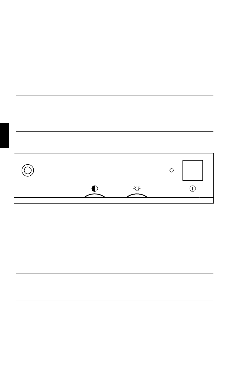
Front panel controls outside of OSM controls are:
Degauss:
eliminates the build-up of stray magnetic fields which alter the
–
correct scan of the electron beams and affect the purity of the
screen colours, focus and convergence.
When pressed, your screen image will jump and waver a bit as
–
the screen is demagnetized.
Caution:
of the Degauss button. Do not hold the button down continuously to
avoid decreasing the life of the degauss circuitry.
Please allow a minimum of 20 minutes to elapse between uses

OSM Controls E-17
Contrast:
adjusts the image brightness in relation to the background.
–
Brightness:
adjusts the overall image and background screen brightness.
–
Power switch:
turns the monitor power on or off. When the power is on, the
–
LED is lit.
LED Power Indicator Light:
located left of the power switch is on and indicates the monitor’s power
mode. Each mode reduces the amount of power used by the monitor.
Mode Light
On green
Stand by yellow
Suspend orange
Off orange
Switched Off no light

E-18 OSM Controls
OSM elements
Typical OSM windows have the following elements:
highlight:
moving icon:
trol will do (also indicates the direction of control when adjusting).
scroll bar:
numeric reading:
compare with a specific setting.
indicates the selected menu or control
provides a quick moving illustration of what the con-
indicates direction of adjustment
provides a number to remember, record or
Accessing OSM
Press any of the control buttons, +,-, arrow up, arrow down, or the
proceed button.
Turning off OSM
When in the main menu: press exit button.
When in submenus: press the exit button twice.

OSM Menus E-19
OSM Menus
Main Menu
On-Screen Manager’s Main Menu of Controls gives you an overview of
the selection of controls available.
ON SCREEN MANAGER
Position
Size
Color Control
Basic Geometry
Advanced Geometry
GlobalSync
OSM Location
The arrows in the bottom or upper right corners indicates further choices
are available. Use the Up or Down control buttons to scroll through all
of the options.
While in the Main Menu, the buttons on the front of the monitor work as
follows:
exits the OSM controls.
exit:
control up/down: moves the highlighted area up/down to select one of
the choices.
control +/-:
proceed:
reset:
Note:
no function.
proceeds to the selected menu choice.
resets all the controls within the highlighted submenu.
resetting the Color Control menu resets all of the colour setting.
The reset function is not needed in the OSM Turn Off Time and
Language Select menus.

E-20 OSM Menus
Position Menu
Position
Up
Left Right
Down
Up/Down: moves the image vertically up or down.
Left/Right: moves the image horizontally left or right.
Size Menu
Size
Tall
Narrow Wide
Short
Tall/Short: increases or decreases the vertical size of the image
Narrow/Wide: increases or decreases the horizontal size of the image
While in the Position/Size Controls Menu, the buttons on the front of the
monitor work as follows:
exit: exits to the main menu.
control up/down: refers to Up/Down and Tall/Short.
control +/-: refers to Left/Right and Narrow/Wide.
proceed: has no function.
reset: resets the current menu control to the factory setting.
Note: a warning window will allow you to choose to reset the current
control or to cancel reset of the current control.

OSM Menus E-21
Color Control Menu
Color Control
Preset:
1 2 3 4 5
Color Gain:
Red
Green
Blue
Preset (Setting): Selects the desired colour setting.
The bar is replaced by the colour setting choice (from 1 to 5). Each
colour setting is adjusted at the factory to the stated degree Kelvin. If a
setting is adjusted, the name of the setting will change from degree
Kelvin to Custom.
Color Gain Red, Green, Blue: Increases or decreases red, green or
blue depending upon which is selected. The change in colour will
appear on screen and the direction (increase or decrease) will be shown
by the colour bars. One colour is always used as the reference colour
and therefore will not changed when adjusted. Your adjustments are
automatically saved instantly.
While in the Color Control Menu, the buttons on the front of the
monitor work as follows:
exit: exits to the main menu.
control up/down: moves the highlighted area up/down to select one of
the choices.
control +/-: moves the bar in the + or - direction to increase or decrease
the adjustment or selects the colour setting (1 through 5).
proceed: moves the highlighted area down to select one of the choices.
reset: resets the current Color Preset to the factory setting.
Note: a warning window will allow you to choose to reset the current
control or to cancel reset of the current control.

E-22 OSM Menus
Basic Geometry Controls Menu
The Basic Geometry controls allow you to adjust the curvature or angle
of the sides of your display.
Basic Geometry
Sides:
In/Out
Left/Right
Tilt
Align
Rotate
Sides In/Out (pin cushion):
increases or decreases the curvature of the
sides either inward or outward.
Sides Left/Right (pin cushion balance):
increases or decreases the
curvature of the sides relative to each other.
Sides Tilt (parallelogram):
increases or decreases the tilt of the sides
either to the left or right.
Sides Align (trapezoidal):
increases or decreases the top of the screen
to be the same as the bottom.
Rotate (raster rotation):
rotates the entire display clockwise or counter
clockwise.
While in the Basic Geometry Controls Menu, the buttons on the front of
the monitor work as follows:
exits to the main menu.
exit:
control up/down:
moves the highlighted area up/down to select one of
the choices.
control +/-:
moves the bar in the + or - direction to increase or decrease
the adjustment.
proceed:
reset:
moves the highlighted area down to select one of the choices.
resets the current highlighted control to the factory setting.
a warning window will allow you to choose to reset the current
Note:
control or to cancel reset of the current control.

OSM Menus E-23
Advanced Geometry Controls Menu
The Advanced Geometry controls allow you to adjust the corners of
your display.
Advanced Geometry
Top:
In/Out
Left/Right
Bottom:
In/Out
Left/Right
Top In/Out (upper corner distortion):
Top Left/Right (upper corner distortion balance):
upper bow.
upper bow
balance.
Bottom In/Out (lower corner distortion):
Bottom Left/Right (lower corner distortion balance):
lower bow.
lower bow
balance.
While in the Advanced Geometry Controls Menu, the buttons on the
front of the monitor work as follows:
exits to the main menu.
exit:
control up/down: moves the highlighted area up/down to select one of
the choices.
control +/-:
moves the bar in the + or - direction to increase or decrease
the adjustment.
proceed:
reset:
Note:
moves the highlighted area down to select one of the choices.
resets the current highlighted control to the factory setting.
a warning window will allow you to choose to reset the
currentcontrol or cancel to reset the current control.

E-24 OSM Menus
GlobalSync
Due to the larger screen size, the MultiSync XP21 features the
GlobalSync control. GlobalSync eliminates colour impurities at the
edges of the screen that may result from the Earth’s magnetic field in
the northern hemisphere. The control is automatically adjusted when
PROCEED is pressed.
GlobalSync
Press:
PROCEED - Start
EXIT - Cancel
OSM Location Menu
You can choose where you would like the OSM image to appear on the
screen. Selecting OSM Location allows you to manually adjust the
OSM Menu left, right, up or down.
OSM Location
Up
Left Right
Down
OSM Turn Off Time Menu
The OSM menu will stay on as long as it is in use.
In the OSM Turn Off Time Menu, you can select how long the monitor
waits after the last touch of a button to shut off the OSM menu. The
preset choices are 10, 20, 30, 60 and 120 seconds.
OSM Turn Off Time
Seconds:
10 20 30 60 120

OSM Menus E-25
Display Mode Menu
Display Mode provides you information about the current resolution
display and technical data including the horizontal and vertical
frequency.
Display Mode
Mode:
H Freq:
V Freq:
H Pol:
V Pol:
Note: If the Mode indicates the symbol "(!)", the reset function for
Position and Size are not effective.
Language Select Menu
OSM Menus are available in six languages.
Vertical Linearity Menu
The vertical linearity controls allow you to adjust the spacing of the
areas on the screen. The object of this control is to ensure that a
one-inch circle is a true one-inch circle whereever it is drawn on the
screen (same image size throughout the total screen area).
Vertical Linearity
Center
Bottom/Top
The best way to determine the vertical linearity is as shown in the
Vertical Linearity Menu. Draw equally spaced (as determined by a
drawing application that has a ruler) horizontal lines across your screen.
E-26 OSM Menus
Using the Center control allows you to adjust the spacing between the
center lines, and using the Bottom/Top control allows you to adjust the
spacing between the top and bottom lines.
Factory Preset
Selecting Factory Preset allows you to reset all OSM settings back to the
factory settings. The following warning statement will appear to confirm
that you do want to reset ALL settings. Individual settings can be reset
by highlighting the control to be reset and pressing the reset button.
WARNING
ABOUT TO RESET
ALL SETTINGS
Press:
RESET - Reset
EXIT - Cancel
Self Test
To make sure, that your monitor is working well, you can choose the
Self Test function in the following way:
Power down your monitor and your PC. Power on the monitor. While
the Exit button is held down, press the Proceed button. The following
picture is shown on the monitor. If you do not press the Exit button to
cancel the Self Test function, the monitor will show a dark screen within
20 seconds.
Self Test Menu
EXIT - Cancel

Trouble Shooting E-27
Trouble Shooting
Please check to be certain that the following items are properly
connected or set, before calling your NEC dealer.
If a non IBM computer or video card, non Apple Macintosh II computer or
video card is being used, make sure the signal timing and pin assignments
meet the specifications outlined in Appendix A and B and C.
Problem, Check these items
No picture. Power Switch and computer power switch should
be in the ON position. MultiSync signal cable
should be completely connected to the video
card/computer. The video card must be completely seated in the slot. Check the connector for
bent or pushed-in pins.
Image is scrolling or
unstable.
LED on the monitor is
not lit or lit with orange
or yellow colour.
Picture is fuzzy. Adjust Contrast and Brightness controls. Push the
Signal cable may not be completely connected to
the computer. Check the pin assignments and
signal timings of the monitor and your video card
with respect to recommended timings and pin
assignments.Check for proper connection or make
sure the video card is PC or Mac compatible and
that the card is properly seated in the computer.
Check SYNC. Switch for its correct position
Power switch should be in the ON position and
the power cord should be connected. Make
certain the computer is not in a power saving
mode (touch keyboard or mouse).
Degauss Button once. Caution: A minimum
interval of 20 minutes should exist before the
Degauss Button is used a second time when not
switching between signal modes. Do not hold
down the button down continuously.

E-28 Trouble Shooting
Problem, Check these items
Picture bounces or a
waving pattern is present
in the picture.
Edges of the display
image are not square.
Display image is not
centred, is too small, or
too large.
Picture has a green tint
or the background
brightness cannot be
turned down.
Colour looks blotchy. Press the Degauss Button once. Do not hold down
Colour is incorrect or
background brightness is
too high and cannot be
decreased.
Move electrical devices that may be causing
electrical interference away from the monitor.
Use the OSM Basic and Advanced Geomatry
Controls to straighten the edges. If possible
position the monitor east.
Adjust Size and Position Controls to adjust the
image in the OSM.
Check the Sync Switch is in the proper position.
Disconnect the C/S input of the BNC cable if you
are using the BNC inputs.
the button down continuously.
The Sync Switch should be in the correct
position. OFF position: When using a Macintosh
II, Quadra, or compatible (and not a Macintosh
LC) with both the Sync on green signal. ON
position: When using computers or video cards
with separate Sync (VGA, SVGA, 8514/A, XGA)
equipped with a 15-pin mini D-sub connector for
the monitor input and composite Sync signals, or
a Macintosh LC, AV’s, PowerBooks, Power
Macs or Quadra 605.
No green color (if using
BNC connection)
Check the BNC cables for propper connection (G
and CS connection may be reversed).

Specifications E-29
Specifications
Picture Tube 41/51 cm (17/21 inch) flat square CRT, 41/51 cm usable
square 0.28 mm Trio dot pitch Dot type black matrix
Medium-short persistence phosphor, dark bulb, glass
with multi-layered anti-static coating
Input Signal Video Analog 0.7 Vp-p 75 Ω Positive
Sync Separate sync.
Horizontal sync.
Vertical sync.
Composite sync.
Sync. on green
Display Colours Analog Input: Unlimited colours (Depends on the
graphics Board)
Synchronisation
Range
Resolution Horizontal XP17 1280
Video Band Width XP17 140 MHz BNC input
Active Display
Area (Factory
Setting)
Horizontal XP17 31 kHz to 82 kHz
XP21 31 kHz to 89 kHz(Automatically)
Vertical 55 to 160 Hz (Automatically)
XP21 1600 dots (non interlaced)
Vertical XP17 1024
XP21 1200 lines (non interlaced)
XP21 190 MHz BNC input
Horizontal XP17 306 mm
XP21 390 mm (Active display area is
dependent upon the signal timing)
Vertical XP17 230 mm
XP21 293 mm (Active display area is
dependent upon the signal timing)
TTL Level
Positive/Negative
Positive/Negative
TTL Level
Positive/Negative
(0.3 Vp-p) Negative

E-30 Specifications
Active Display
Area (Full Scan)
Rated Voltage AC 220-240 V 50/60 Hz
Rated Current XP17 1.3 A
Dimensions XP17 417 (W) x 433 (H) x 489 (D) mm
Weight XP17 23.5 kg
Environmental
Considerations
Horizontal XP17 316 mm
XP21 402 mm (Active display area is
dependent upon the signal timing)
Vertical XP17 237 mm
XP21 301 mm (Active display area is
dependent upon the signal timing)
XP21 1.8 A
XP21 512 (W) x 529 (H) x 572 (D) mm
XP21 35.8 kg
Operating
Temperature 0° C to + 35° C
Humidity 30% to 80%
Storage
Temperature -20° C to + 60° C
Humidity 10% to 90%
Technical specifications are subject to change without notice.

Deutsch

Vorstellung D-1
Vorstellung
Herzlichen Glückwunsch zum Kauf Ihres NEC MultiSync XP-Serie
Farbmonitors!
Neu an diesem Monitor sind neben den von NEC MultiSync-Monitoren
gewohnten Eigenschaften unter anderemMicrosoft’s Plug and Play und
der On Screen Manager (OSM), der eine menügesteuerte Einstellung
des Monitors erlaubt, sowie Erweiterungen im ErgoDesign.
Die NEC MultiSync XP-Serie von Monitoren ist ohne weitere
Installationsarbeiten in Betrieb zu nehmen. Er verarbeitet ein breites
Spektrum von Eingangssignalen diverser Computersysteme und
Grafikstandards ohne Einstellungs- und Justierarbeiten. Dies erlaubt eine
Steigerung der Bildschirmauflösung ohne Anschaffung eines neuen
Monitors.
Der MultiSync XP-Serie Monitor ist strikt nach den Richtlinien des
ErgoDesigns entwickelt worden. ErgoDesign beschreibt eine
Philosophie mit dem Ziel, dem Benutzer von NEC MultiSync
Monitoren ein Maximum an Komfort und Produktivität zu bieten.
Hierzu gehören normierte Stromsparfunktionen, stark verminderte
Abstrahlungswerte sowie Recycling.
Besondere Eigenschaften
Plug and Play
Konfigurationsprobleme bei der Installation von EDV- und
Peripheriegeräten. NEC hat die Plug and Play Fähigkeiten in enger
Zusammenarbeit mit Microsoft mitentwickelt, so daß NEC Monitore
von allen Systemen mit Plug and Play Funktion automatisch richtig
erkannt und konfiguriert werden.Die Monitore der XP-Familie teilen
ihren Typ und ihre Leistungsmerkmale normgerecht dem System mit.
Die enge Partnerschaft zwischen NEC und Microsoft ermöglicht Ihnen
einfachste Installation, Konfiguration und Einstellung Ihres NEC
Monitors.
ist die in Windows 95 integrierte Antwort Microsofts auf

D-2 Besondere Eigenschaften
ACCESS.bus ist ein in Kürze realisierter neuer Industriestandard zur
Kommunikation zwischen Peripheriegeräten. Über ein dünnes Kabel
kommunizieren bidirektional Geräte wie Monitor, Tastatur oder Maus
mit der Zentraleinheit des Systems. So kann der PC jederzeit die an ihn
angeschlossenen Geräte erkennen und steuern. Es können zu jeder Zeit
ACCESS.bus geeignete Geräte über einen speziellen ACCESS.bus
Stecker mit dem System verbunden oder gelöst werden. Hierbei ist es
unrelevant, ob der PC ein- oder ausgeschaltet ist.
Die ACCESS.bus Fähigkeiten schließen nicht nur die Vorteile von
Plug&Play mit ein, sondern erlauben auch eine automatische
Einstellung der optimalen Systemkonfiguration. So können Sie sicher
sein, daß immer die höchstmögliche Auflösung und Bildwiederholrate
von Grafikkarte und Monitor eingestellt wird. Zusätzlich kann der
Monitor über die ACCESS.bus Verbindung durch Systemsoftware oder
durch die Tastatur bedient werden. Hierzu befindet sich eine
Windows-Software im Lieferumfang, die das OSM Menü des Monitors
simuliert. Dies erhöht deutlich die Funktionalität und
Bedienerfreundlichkeit der XP Monitorfamilie.
ACCESS.bus reduziert auch den Kabelwirrwarr auf Ihrem Schreibtisch:
Plazieren Sie Ihren PC unter Ihrem Schreibtisch, so können Sie Maus und
Tastatur in Reihe an der ACCESS.bus Buchse Ihres MultiSync
XP-Monitors anschließen. Die angeschlossenen Geräte können zu jeder
Zeit vom System getrennt werden, ohne den Arbeitsfluß zu unterbrechen.
Die Monitor-Manager-Software ist ein Paket von
Computerprogrammen, das Ihnen die Arbeit mit Ihrem Monitor, den
Plug und Play - sowie den ACCESS.bus Funktionen erleichtert. Hierzu
gehört auch das Poer Manager Programm, daß es Ihnen ermöglicht, die
Energiesparfunktionen des Monitors auch ohne eine geeignete
Grafikkarte nach VESA DPMS zu steuern.
Über den ACCESS.bus steuern Sie den On Screen Manager (OSM) des
Monitors duch eine Image Manager Software. Zusätzlich zu den
Funktionen des OSM erlaubt das Programm eine Speicherung von einer
beliebigen Anzahl von Einstellungen. Ein Spezialität ist die Kopplung
bestimmter Einstellungen an den Start eines Programmes. So können
einer Multimedia Applikation viele Farben bei niedriger Auflösung und
einer Tabellenkalkulation wenige Farben bei hoher Auflösung
zugewiesen werden.

Besondere Eigenschaften D-3
Die Color Manager Software heißt Colorific und ist eine
Farbkalibriersoftware die Monitorwidergabe und Druckerausgabe mit
Hilfe von Kodak’s Farbmanagement Sytem unter MS-Windows
angleicht. Dies funktioniert auf Apple Systemen mit dem ColorSync
Programm.
DPI on the Fly ist der Resolution Manager für Macintosh Computer. Er
erlaubt ein Umschalten zwischen den vom System möglichen
Bildschirmauflösungen ohne Tausch von Anschlußkabeln. So kann eine
der Anwendung ädiquate Bildschirmauflösung einfach gewählt werden.
Der Intelligent Power Manager (intelligenter Energiesparer) abgekürzt
IPM, ist eine fortschrittliche Einrichtung zum Energiesparen. Nach den
Richtlinien des Energy Stars der amerikanischen Umweltbehörde und
der europäischen NUTEK konzipiert, sparen die Monitore der XP-Serie
Energie und Kosten, indem bei Arbeitspausen die Monitor teilweise
abgeschaltet werden. Dadurch wird zusätzlich die Lebensdauer der
Monitore verlängert. Wie von der Nutek Spezifikation 803299
gefordert, verbrauchen die Monitore der XP-Serie im Stand by Modus
weniger als 30 Watt und im Suspend Modus weniger als 8 Watt. In der
höchsten Stufe der Energieeinsparung werden nur noch ca. 10% der
Energie verbraucht, oder aber 90% Energie eingespart.
Hinweis: Die Energiespareinrichtung kann nur von einer Grafikkarte
aktiviert werden, die diese Funktion gemäß DPMS von VESA, unterstützt.
Der OSM (On Screen Manager) vereinfacht die Benutzung des digitalen
Kontrollsystems der Monitore. Die Berührung eines der auf der
Vorderseite des Monitors angebrachten Bedienelemente schaltet das
OSM ein. Auf dem Monitor erscheint in deutscher Sprache ein einfach
zu bedienendes Menüsystem, das im Dialog mit dem Benutzer die
Einstellung aller Monitorparameter erlaubt. Kleine Sinnbilder (Icons)
erleichtern hierbei die Arbeit.
Das OptiClear Coating reduziert drastisch alle Reflektionen von
Lichtquellen der Umgebung ohne dabei Schärfe oder Helligkeit der
Röhre zu beeinflussen.
Eine Bildpunktgröße von 0,28mm verbessert in Verbindung mit einer
Invar Shadow Maske und dem Dual Dynamic Beam Focus die

D-4 ErgoDesign
Abbildungsschärfe und zeigt so mehr Details. Dies erlaubt Ihren Augen
über den Monitor zu fliegen und so den Bildschirminhalt einfacher
wahrzunehmen.
Der BNC/D-SUB Wahlschalter an der Vorderseite des Monitors erlaubt
die Umschaltung zwischen zwei gleichzeitig am Monitor angeschlossenen
Computern. Hierzu wird ein Monitor über das MultiCable und ein weiterer
über die BNC-Buchsen angeschlossen. Einfach durch betätigen des
BNC/D-SUB-Wahlschalters an der Vorderseite wechseln Sie nun
zwischen den angeschlossenen Computern.
Farbreinheit heißt die Funktion, die beim Model XP21 eine Anpassung der
Bildröhre an negative Auswirkungen des Erdmagnetfeldes durchführt.
Hierdurch werden mögliche Farbverfälschungen ausgeglichen.
ErgoDesign
Emissionstest
ErgoDesign steht neben einem gefälligen Gehäuse auch für reduzierte
elektrostatische und magnetische Emissionen. Die NEC MultiSync
Monitore sind so entwickelt worden, daß von magnetischen Feldern
ausgehende potentielle Gefahren einer andauernden Bildschirmarbeit
weitgehend vermieden werden.
Die NEC ErgoDesign Monitorfamilie wurde durch das SEMKO Institut
in Schweden und den TÜV Rheinland in Köln getestet. Diese Institute
prüfen nach den MPR-Richtlinien der schwedischen Strahlenschutz
Behörde SWEDAC. Das Bestehen dieser Tests garantiert die Erfüllung
dieser derzeit weltweit restriktivsten Richtlinien. Die Monitore der
XP-Serie erfüllen die SWEDAC Norm MPR 1990:8 (MPRII) und bei
Verwendung eines optional erhältlichen Bildschirmfilters TCO 92.
Die Verminderung der statischen Elektrizität verhindert zum einen
elektrische Entladungen bei Berührung, zum anderen wird die
Verschmutzung der Bildröhre reduziert.

ErgoDesign D-5
Technologie
Die Bauart der MultiSync Monitore erlaubt die automatische Anpassung
des Monitors an die Frequenzen der gerade benutzten
Bildschirmauflösung. Erkannt werden unter anderem IBM kompatible
Systeme und Mitglieder der Macintosh Familie.
Gesteigerte Bildschirmauflösung führt zu besserer Schärfe der
Abbildung. Der MultiSync XP17/XP21 Monitor unterstützt ein noch
breiteres Spektrum an Bildschirmauflösungen, die Ihren Anforderungen
heute und in Zukunft gerecht werden.
Der MultiSync XP17/XP21 unterstützt eine breite Palette von
Grafikstandards. Diese sind:
•
VGA (640 x 480) mit 60, 72 und 75 Hz
•
SuperVGA (800 x 600) mit 56 und 60, 72 und 75 Hz
•
MAC II (640 x 480) mit 66,7 Hz
•
Macintosh 832 x 624 mit 75 Hz
•
Macintosh 1024x768 mit 75 Hz
•
XGA und 8514/A (1024 x 768) interlaced
•
1024 x 768 non-interlaced 60, 70 und 75 Hz
•
XGA2 (1024 x 768)mit 72 und 75 Hz (spezielles Kabel benötigt.
•
1152x900 mit 66 und 76 Hz (spezielles Kabel benötigt)
•
Macintosh 1152x870 mit 75 Hz
•
1280x1024 mit 60, 70 und 75 Hz
•
1600x1200 in Abhängigkeit von der vertikalen und horizontalen Ablenkfrequenz. (nur XP21)
•
1280x1024 ist beim Model XP21 empfohlen.

D-6 Lieferumfang
Lieferumfang
Die folgende Abbildung zeigt den Lieferumfang des NEC MultiSync
XP-Serie Farbmonitors. Öffnen Sie vorsichtig die Verpackung Ihres
Monitors und entnehmen Sie alle zum Monitor gehörenden Teile. Sollten
Teile fehlen oder beschädigt sein, so wenden Sie sich bitte umgehend an
Ihren NEC-Fachhändler. Karton und Verpackungsmaterial sollten Sie für
einen späteren Transport Ihres Monitors aufbewahren.
MultiSync XP-Serie Farbmonitor mit verstellbarem Standfuß
➀
Netzkabel
➁
Bedienerhandbuch
➂
Multicable
➃
2 Disketten für Kommunikationssoftware
Farbreferenzkarte für Colorific
Hinweis: Der verstellbare Standfuß des Monitors kann bei engen
Platzverhältnissen entfernt, und durch optional erhältliche
Gummistopfen ersetzt werden.

Aufstellen D-7
Aufstellen
Um eine optimale Abbildungsqualität Ihres MultiSync Monitors zu
gewährleisten, sollten Sie folgende Punkte bei der Aufstellung des
Monitors beachten:
Plazieren Sie den Monitor nicht in direktem Sonnenlicht.
–
Stellen Sie ihn etwas unterhalb Ihrer Augenhöhe auf, um einen
–
optimalen Betrachtungswinkel zu erhalten.
Achten Sie darauf, daß die Lüftungsschlitze des Monitors nicht
–
verdeckt sind, um eine optimale Wärmeabfuhr zu
gewährleisten.
Stellen Sie keine schweren Gegenstände auf das Netzkabel des
–
Monitors. Beschädigte Netzkabel können zu Brand oder
Stromschlag führen.
Plazieren Sie Ihren Monitor nicht in der Nähe von
–
Elektromotoren oder anderen Geräten, die starke
elektromagnetische Felder erzeugen.
Benutzen Sie den Monitor nur in trockener, sauberer
–
Umgebung.
Transportieren Sie den Monitor mit der nötigen Vorsicht.
–
Stellen Sie die Helligkeit der Bildröhre so ein, daß das
–
Hintergrundraster der Röhre nicht sichtbar ist.
Aus Gründen der Ergonomie sollten Sie die Kontrasteinstellung
–
nicht auf ihren maximalen Wert bringen.
Der Knopf zur Entmagnetisierung der Bildröhre ist immer dann
–
zu betätigen, wenn einzelne Bereiche der Bildröhre
Farbverschiebungen aufweisen.
Achtung: Betätigen Sie den Knopf zur Entmagnetisierung nie länger als
10 Sekunden.

D-8 Aufstellen
–
Aus ergonomischen Gründen empfehlen wir die Benutzung
folgender Vertikalfrequenzen, außer Interlaced-Signalen:
bei hellem Untergrund 70 bis 120 Hz.
–
Es wird empfohlen, nicht mit der Primärfarbe Blau auf
dunklem Hintergrund zu arbeiten. Der mangelnde Kontrast
erschwert die Lesbarkeit der Abbildung und strapaziert die
Augen sehr stark.
–
Aus ergonomischen Gründen wird empfohlen, die
Benutzung der Standardeinstellung für Bildgröße und
Bildlage beizubehalten.
–
Aus ergonomischen Gründen empfehlen wir die Benutzung
der Standardeinstellung für die Farbeinstellung.
–
Die Werkeinstellung der Kissenentzerrung sollte aus
ergonomischen Gründen nicht verändert werden.
–
Zur vollständigen Trennung vom Stromnetz ist der Netzbzw. Gerätestecker zu ziehen.
–
Schließen Sie den Monitor an eine Steckdose an, die sich
leicht zugänglich, in der Nähe des Gerätes befinden muß.
–
Die Benutzung des mitgelieferten Netzkabels wird
empfohlen. Sollten Sie das Netzkabel durch ein anderes
ersetzen, so muß ein Netzkabel vom Typ H05VV-F zum
Anschluß des Monitores verwendet werden!
Zur Reinigung der Bildröhre benutzen Sie am besten ein weiches Tuch
und einen neutralen Reiniger.

Installation D-9
Installation
Die folgende Abbildung faßt den Anschluß eines MultiSync
XP17/XP21 Monitors in wichtigen Schritten zusammen.
Weitere Informationen zur Installation an verschiedenen
Computersystemen finden Sie auf den folgenden Seiten.
Wir d d e r B N C - E i n ga n g b e nutzt?
Nein
Setzen Sie den BNC/D-SUB-
Schalter nach unten
Ist Ihr Computer ein Macintosh
Computer?
Nein
Setzen Sie den SYNC-Schalter in
die ON Position.
Verbinden Sie das Signalkabel des
Monitors mit der Grafikkarte
Verbinden Sie das Netzkabel mit
dem Monitor und einer Wandsteck-
dose.
Schalten Sie PC und Monitor ein.
Benutzen Sie das OSM um das Bild
Ihren Gewohnheiten anzupassen.
Setzen Sie den BNC/D-SUB-Schal-
Ja
Ist Ihr Computer ein Powerbook, LC,
Ja
ter nach oben
AV, PowerMac oder Quadra 605?
Ja
Nein
Setzen Sie den SYNC-Schalter in die
OFF Position.
Is t die Abbildung korrekt?
Ja
Freuen Sie sich über Ihren Monitor.
Nein
Ja
Lesen Sie das Kapitel Probleme
&Lösungen
Problem behoben?
Nein
Fragen Sie Ihren NEC-Händler

D-10 Installation
Installation
Anschluß an NEC-, IBM- und kompatible PC’s
Der NEC MultiSync XP-Serie Farbmonitor ist geeignet für NEC PC’s
oder IBM XT, AT, 386, 486, PS/2 und dazu kompatible Computer. Ihr
System sollte entweder einen eingebauten Grafikadapter oder eine
installierte Grafikkarte besitzen. Beide Varianten haben eine
Videoausgangsbuchse zum Anschluß eines Monitors. Sollten Sie nicht
sicher sein, an welche Buchse der Monitor anzuschließen ist, so lesen
Sie dies im Benutzerhandbuch der Grafikkarte oder des Computers
nach. Im Zweifelsfall fragen Sie Ihren Fachhändler.
Beim Anschluß eines Monitors an Ihren Computer sind folgende Punkte
zu beachten:
1. Schalten Sie die Stromversorgung von Computer und Monitor aus.
2. Falls notwendig, installieren Sie eine Grafikkarte nach den
Anweisungen im Benutzerhandbuch der Grafikkarte.
3. Stellen Sie sicher, daß der BNC/D-SUB-Schalter an der
Vorderseite sich in Stellung D-SUB (nach unten) befindet.
4. Schließen Sie die 15-pin mini D-SUB-Buchse (die kleinere)
des Multicables am Video-Ausgang Ihres Computers an.
5. Schließen Sie die 15-pin D-SUB-Buchse(die größere) des
Multicables am Monitor an.
6. Verbinden Sie das mitgelieferte Netzkabel auf einer Seite mit
dem Monitor und auf der anderen Seite mit einer geerdeten
Wandsteckdose in der Nähe des Monitors.
7. Schalten Sie Monitor und Computer ein.
8. Hiermit ist der Anschluß des Monitors abgeschlossen.
Sollten sich hierbei Probleme ergeben, so lesen Sie bitte den Abschnitt
,,Hilfe bei Problemen”.

Installation D-11
Anschluß an Macintosh Computer
Der NEC MultiSync XP-Serie Monitor ist Dank des MultiCables geeignet
für den Anschluß an Computer der Macintosh Familie. Ihr System sollte
entweder einen integrierten Grafikadapter oder eine in einem NU-Bus oder
PDS-Steckplatz eingebaute Grafikkarte besitzen. Beide Varianten haben
eine Videoausgangsbuchse zum Anschluß eines Monitors.
Benutzer eines Power Macintosh 6100/60 benötigen zum Anschluß des
Monitors das mit dem Computer gelieferte Kabel HDI-45 zusätzlich
zum optional erhältlichen Macintosh Adapter.
Verfahren Sie wie folgt, um Ihren Monitor an einen Macintosh
Computer anzuschließen:
1. Schalten Sie die Stromversorgung von Computer und Monitor aus.
2. Falls notwendig, installieren Sie eine Grafikkarte nach den
Anweisungen im Benutzerhandbuch der Grafikkarte.
3. Benutzen Sie einen Computer der Quadra Serie oder der
Macintosh Familie, so muß der SYNC-Schalter an der
Rückseite in der Position OFF stehen. Bei allen anderen
Apple Computern die im Quick Start aufgeführt sind, muß er
in Position ON gebracht werden.
4. Stellen Sie sicher, daß der BNC/D-SUB-Schalter an der
Vorderseite sich in Stellung D-SUB (nach unten) befindet.
5. Schließen Sie die 15-pin mini D-SUB-Buchse(die kleinere)
des Multicables am Video-Ausgang Ihres Computers an.
6. Schließen Sie die 15-pin D-SUB-Buchse(die größere) des
Multicables am Monitor an.
7. Verbinden Sie das mitgelief erte Netzkabel auf einer Seite mit
dem Monitor und auf der anderen Seite mit einer geerdeten
Wandsteckdose in der Nähe des Monitors.
8. Schalten Sie Monitor und Computer ein.
8. Hiermit ist der Anschluß des Monitors abgeschlossen.
Sollten sich hierbei Probleme ergeben, so lesen Sie bitte den Abschnitt
,,Hilfe bei Problemen”.

D-12 Installation
Anschluß an andere Computersysteme
Möchten Sie Ihren MultiSync XP-Serie Farbmonitor an ein
Computersystem oder an eine Grafikkarte anschließen, die nicht mit
dem im Anhang (Appendix) beschriebenen PRESET-Signal kompatibel
ist, oder deren Anschlußbelegung von der im Anhang beschriebenen
abweicht, so verfahren Sie wie folgt:
1. Schalten Sie Monitor und Computer aus.
2. Überprüfen Sie die Anschlußbelegung der Ausgangsbuchse
Ihres Computersystems oder Ihrer Grafikkarte.
3. Überprüfen Sie Signalverhalten und Amplitude Ihrer
Grafikkarte.
4. Stellen Sie sicher, daß Anschlußbelegung und Signalverhalten
mit denen des MultiSync XP17/XP21 kompatibel sind.
5. Verbinden Sie das mit der Grafikkarte gelieferte Signalkabel
mit dem Monitor und mit dem Videoausgang des Computers.
6. Verbinden Sie das mitgelieferte Netzkabel auf einer Seite mit
dem Monitor und auf der anderen Seite mit einer geerdeten
Wandsteckdose in der Nähe des Monitors.
7. Schalten Sie Monitor und Computer ein.
8. Justieren Sie Größe und Lage der Abbildung nach Ihren
Anforderungen.
9. Dies beendet die Installation.
Sind Sie nicht sicher, ob Ihr MultiSync XP-Serie Farbmonitor für den
gewünschten Einsatzzweck geeignet ist, so fragen Sie Ihren
autorisierten NEC-Fachhändler.

Installation D-13
Anschluß an Computer über BNC-Kabel
Der NEC MultiSync XP-Serie Farbmonitor ist geeignet für einen
Anschluß über BNC-Buchsen. So können Signale größerer Bandbreite
sauber übertragen werden.
Beim Anschluß eines Monitors an Ihren Computer sind folgende Punkte
zu beachten:
1. Schalten Sie die Stromversorgung von Computer und Monitor aus.
2. Falls notwendig, installieren Sie eine Grafikkarte nach den
Anweisungen im Benutzerhandbuch der Grafikkarte.
3. Stellen Sie sicher, daß der BNC/D-SUB-Schalter an der
Vorderseite sich in Stellung BNC (nach oben) befindet.
4. Schließen Sie die D-SUB-Buchse oder die entsprechende
Buchse des BNC-Kabels an den Video-Ausgang Ihres
Computers an.
5. Schließen Sie die BNC Buchsen entsprechend der Kennung
Rot Grün Blau an die gleichen Stecker am Monitor an. Hat
Ihr BNC Kabel nur vier Anschlüsse, so wird das Composite
SYNC-Kabel an den Anschluß HS/CS des Monitors
angeschlossen. Ist ein fünfter Stecker am Kabel vorhanden, so
schließen Sie es am Anschluß VS am Monitor an.
6. Verbinden Sie das mitgelief erte Netzkabel auf einer Seite mit
dem Monitor und auf der anderen Seite mit einer geerdeten
Wandsteckdose in der Nähe des Monitors.
7. Schalten Sie Monitor und Computer ein.
8. Hiermit ist der Anschluß des Monitors abgeschlossen.
Sollten sich hierbei Probleme ergeben, so lesen Sie bitte den Abschnitt
,,Hilfe bei Problemen”.

D-14 Installation
Anschluß von zwei Systemen gleichzeitig (z.B. ein IBM
und ein Macintosh System).
Die Monitormodelle der XP-Serie sind so entwickelt worden, daß zwei
Computersysteme gleichzeitig angeschlossen werden können. Die
Umschaltung zwischen den Systemen erfolgt über den frontseitigen
BNC/D-SUB-Schalter.
Diese Lösung erfordert es, daß ein System über die BNC-Buchsen
angeschlossen wird. Wird dies nicht von der Grafikkarte eines Systems
unterstützt, so ist ein BNC-Adapterkabel zu beschaffen.
Verfahren Sie wie folgt, um zwei Systeme gleichzeitig an Ihrem
Monitor zu installieren.
1. Verfahren Sie wie zuvor in den Abschnitten über den
Anschluß von IBM oder MAcintosh Computern beschrieben,
um einen Monitor über das MultiCable anzuschließen.
2. Verfahren Sie wie im Abschnitt über den Anschluß von
Computern mit BNC-Kabeln beschrieben, um den zweiten
Computer am Monitor zu installieren.
3. Schalten Sie alle Geräte ein.
4. Die beendet die Installation.
5. Benutzen Sie den BNC/D-SUB-Schalter um zwischen beiden
Systemen zu wechseln.
Sollten sich hierbei Probleme ergeben, so lesen Sie bitte den Abschnitt
,,Hilfe bei Problemen”.

OSM-Menü D-15
OSM-Menü
Das neue OSM-Menü (On Screen Manager) von NEC zeigt die derzeit
komfortabelste Art der Monitoreinstellung. Tasten an der Vorderseite
des Monitors helfen Ihnen bei der Navigation durch ein grafisches
Menüsystem. Parallel zu Ihrer Auswahl im Menüsystem zeigen Ihnen
kleine Sinnbilder (Icons) die Auswirkungen Ihrer Auswahl.
Mit dem OSM-Menü können die Parameter Bildgröße, Bildlage,
Bildgeometrie und Farbanpassung des Digital Control-Systems
gesteuert werden. Alle Einstellungen werden nach ca. 5 Sekunden
dauerhaft gespeichert. Die Einstellungen des jeweils aktiven
Menüpunktes können jederzeit durch drücken des Reset-Knopfes auf
die Werkeinstellungen zurückgesetzt werden.
Die folgende Abbildung zeigt die Lage der Tasten zur Bedienung des
OSM-Menüs:
Mit der Taste
OSM-Menü verlassen.
Die
Control-Tasten ,,auf” und ,,ab”
Bereich nach oben oder unten um einen Menüpunkt auszuwählen.
Mit den
eines Parameters erhöht oder verringert. Diese beiden Tasten haben im
Hauptmenü keine Funktion.
Die Taste
Im Hauptmenü wird so in einen Untermenüpunkt verzweigt, im
Untermenü eine Auswahl bestätigt
Control-Tasten ,,+” und ,,-”
Proceed
wird der aktuelle Menüpunkt, im Hauptmenü das
Exit
steuern den hervorgehobenen
wird die aktuelle Einstellung
dient der Auswahl eines markierten Menüpunktes.
D-16 OSM-Menü
Reset setzt die Einstellungen des aktiven Menüpunktes auf die
Werkeinstellungen zurück. Wird diese Taste im Hauptmenü gedrückt,
so werden alle Parameter des markierten Untermenüs, in einem
Untermenü nur der aktuelle Parameter auf die Werkeinstellungen
zurückgesetzt.
Hinweis: Wird die Reset Taste gedrückt, so erscheint ein Fenster mit
einer Warnung, die darauf hinweist, daß Sie den aktuellen Menüpunkt
auf die Werkseinstellung zurücksetzen wollen. Sie haben die Wahl,
fortzusetzen oder den Vorgang abzubrechen.
Weitere Bedienelemente an der Frontseite
Die Degauss-Taste dient der Entmagnetisierung der Bildröhre indem
ein möglicherweise entstandenes Magnetfeld beseitigt wird. Hierdurch
wird die Führung des Elektronenstrahls der Bildröhre verbessert und die
Farbreinheit wieder hergestellt.
Nach Betätigung der Degauss-Taste zittert der Bildschirm kurzzeitig.
Hierauf ist die Bildröhre entmagnetisiert.
Hinweis: Drücken Sie die Degauss-Taste nur kurzzeitig und auf keinen
Fall kontinuierlich. Warten Sie nach einer Entmagnetisierung
mindestens 20 Minuten, bis Sie den Vorgang wiederholen.
Der Kontrastregler erlaubt eine Einstellung der Bildhelligkeit in
Abhängigkeit vom Bildschirmhintergrund.
Der Helligkeitsregler regelt die gesamte Helligkeit der Abbildung.
Mit dem Netzschalter wird der Monitor ein-/ und ausgeschaltet.

OSM-Menü D-17
Die Netz-LED zeigt den Betriebzustand des Monitors an. Hierbei kann
die LED unterschiedliche Farben annehmen. Die Bedeutung der
einzelnen Farben kann der folgenden Tabelle entnommen werden.
Modus Farbe
Ein grün
Stand by (Bereitschaft) gelb
Suspend orange
Aus orange
Ausgeschaltet aus (dunkel)
Elemente der OSM-Bildschirmanzeige
Ein markierter Bereich zeigt den gerade aktiven Menüpunkt oder die
Einstellung.
Ein sich bewegendes Sinnbild (Icon) zeigt Ihnen die Bedeutung der
gerade vorgenommenen Einstellungen.
Eine Laufleiste zeigt die Richtung der Einstellung.
Eine numerische Zahl zeigt eine Einstellung im Klartext. Diese Zahl
kann zu Vergleichen oder zum Notieren verwendet werden.
Zugriff auf das OSM-Menü
Durch betätigen einer der Tasten Control auf/ab, Control +/- oder
Proceed, wird das OSM-Menü am Bildschirm eingeblendet.
Das OSM-Menü wird verlassen, in dem die Exit-Taste im Hauptmenü
des OSM gedrückt wird.

D-18 Die OSM-Menüstruktur
Die OSM-Menüstruktur
Das Hauptmenü
Das Hauptmenü des OSM gibt Ihnen einen Überblick über die
Funktionen und Untermenüs des OSM.
ON SCREEN MANAGER
Bildlage
Bildgröße
ColorControl
Geometrie 1
Geometrie 2
Farbreinheit
OSM Position
Ein Pfeil in der rechten oberen oder unteren Ecke zeigt an, das weitere
Menüpunkte mit den auf/ab-Tasten erreicht werden können.
Im Hauptmenü haben die Tasten an der Frontseite des Monitors die
folgende Bedeutung:
führt zu einem Verlassen des OSM-Menüs
exit:
control auf/ab:
control +/-:
proceed:
setzt alle Einstellungen in dem markierten Untermenü auf die
reset:
bewegt die Markierung zu den einzelnen Menüpunkten.
keine Funktion.
verzweigt in das markierte Untermenü.
Werkeinstellung zurück.
Hinweis:
Im Color Control-Untermenü werden alle Farbeinstellung auf
die Werkeinstellung zurück gesetzt. In den Untermenüs OSM
Anzeigedauer und Sprachauswahl hat Reset keine Funktion.

Die OSM-Menüstruktur D-19
Bildlage Menü
Bildlage
Oben
Links Rechts
Unten
Oben/Unten: verschiebt das Bild von oben nach unten.
Links/Rechts: verschiebt das Bild von rechts nach links.
Bildgröße Menü
Bildgröße
Groß
Schmal Breit
Klein
Groß/Klein: macht das Bild größer oder kleiner.
Schmal/Breit: macht das Bild breiter oder schmaler.
Im Bildlage/Bildgröße-Menü haben die Tasten an der Frontseite des
Monitors die folgende Bedeutung:
exit: führt zum Hauptmenü des OSM-Menüs.
control auf/ab: bewegt den Pfeil zu den einzelnen Untermenüpunkten.
control +/-: erhöht oder verringert den eingestellten Wert.
reset: setzt alle Einstellungen in dem markierten Untermenü auf die
Werkeinstellung zurück.
Hinweis: ein Fenster mit einer Warnmeldung erlaubt den Reset-Vorgang
abzubrechen oder endgültig auzuführen.

D-20 Die OSM-Menüstruktur
ColorControl-Menü
ColorControl
Einstellung:
1 2 3 4 5
Farbintensität:
Rot
Grün
Blau
Einstellung: erlaubt die Auswahl zwischen 5 verschiedenen
Farbeinstellungen, die individuell geändert werden können.
Farbintensität: erlaubt die Änderung der Farbtemperatur.
Rot, Grün, Blau: erlaubt eine individuelle Anpassung des Anteils der
jeweiligen Farbe.
Im ColorControl-Menü haben die Tasten an der Frontseite des Monitors
die folgende Bedeutung:
exit: führt zum Hauptmenü des OSM-Menüs.
control auf/ab: bewegt den Pfeil zu den einzelnen Untermenüpunkten.
control +/-: erhöht oder verringert den Anteil der jeweiligen Farbe.
proceed: verzweigt in das markierte Untermenü.
reset: setzt alle Einstellungen in dem markierten Untermenü auf die
Werkeinstellung zurück.
Hinweis: ein Fenster mit einer Warnmeldung erlaubt den
Reset-Vorgang abzubrechen oder endgültig auzuführen.
Die werkseitige Voreinstellung der Farben wurde durch repräsentative
Umfragen ermittelt und ist für die meisten Applikationen geeignet.

Die OSM-Menüstruktur D-21
Geometrie 1-Menü
Geometrie 1
Seiten:
Ein/Aus
Li./Re.
Parallel
Trapez
Drehen
Seiten Ein/Aus: justiert die Krümmung der Bildseiten nach innen oder außen.
Seiten Li./Re.: justiert die Krümmung der Bildseiten nach links oder rechts.
Seiten Parallel: justiert die Neigung der Bildseiten nach links oder rechts.
Seiten Trapez: justiert die Breite des oberen Bildrandes gleich der
Breite des unteren Bildrandes.
Drehen: erlaubt eine Drehung des Bildes.
Im Geometrie-Menü haben die Tasten an der Frontseite des Monitors
die folgende Bedeutung:
exit: führt zum Hauptmenü des OSM-Menüs
control auf/ab: bewegt die Markierung zu den einzelnen
Untermenüpunkten.
control +/-: erhöht oder verringert den Wert der Anpassung.
proceed: verzweigt in das markierte Untermenü.
reset: setzt alle Einstellungen in dem mit dem Pfeil markierten
Untermenü auf die Werkeinstellung zurück.
Hinweis: ein Fenster mit einer Warnmeldung erlaubt den
Reset-Vorgang abzubrechen oder endgültig auzuführen.

D-22 Die OSM-Menüstruktur
Geometrie 2-Menü
Geometrie 2
Oberer Rand
Ein/Aus
Li./Re.
Unterer Rand
Ein/Aus
Li./Re.
Oberer Rand Ein/Aus: justiert die Krümmung der oberen Bildkanten
nach innen oder außen.
Oberer Rand Li./Re.: justiert die Krümmung der oberen Bildkanten
nach links oder rechts.
Unterer Rand Ein/Aus: justiert die Krümmung der unteren Bildkanten
nach innen oder außen.
Unterer Rand Li./Re.: justiert die Krümmung der unteren Bildkanten
nach links oder rechts.
Im Geometrie 2-Menü haben die Tasten an der Frontseite des Monitors
die folgende Bedeutung:
exit: führt zum Hauptmenü des OSM-Menüs.
control auf/ab: bewegt die Markierung zu den einzelnen
Untermenüpunkten.
control +/-: erhöht oder verringert den Wert der Anpassung.
proceed: verzweigt in das markierte Untermenü.
reset: setzt alle Einstellungen in dem markierten Untermenü auf die
Werkeinstellung zurück.
Hinweis: ein Fenster mit einer Warnmeldung erlaubt den
Reset-Vorgang abzubrechen oder endgültig auzuführen.

Die OSM-Menüstruktur D-23
Farbreinheit
Bedingt durch die größere Bildröhre des Modells XP21 wurde dort mit
Farbreinheit eine Anpassungseinrichtung an das Erdmagnetfeld
eingebaut. Diese Schaltung verhindert Farbverfälschungen die durch
den Einfluß des Erdmagnetfeldes in der nördlichen Hemisphere
entstehen können. Nach Drücken des PROCEED - Knopfes erfolgt eine
automatische Korrektur. Zeigt der Bildschirm ,,Einstellungen komplett”,
so ist der Vorgang abgeschlossen.
Farbreinheit
Drücken Sie:
PROCEED - Start
EXIT - Stornieren
OSM-Position
OSM Position
Oben
Links Rechts
Unten
Verschieben Links/Rechts:
verschiebt den Erscheinungsort des
OSM-Menüs nach links oder rechts.
Verschieben Oben/Unten:. verschiebt den Erscheinungsort des
OSM-Menüs nach oben oder unten.

D-24 Die OSM-Menüstruktur
OSM-Anzeigedauer
OSM Anzeigedauer
Sekunden:
10 20 30 60 120
Sekunden: Definiert die Verweildauer der OSM-Anzeige auf dem
Bildschirm. Ohne eine Eingabe des Benutzers bleibt die Anzeige des
OSM-Menüs für die definierte Anzahl Sekunden auf dem Bildschirm
stehen.
Grafik Modus
Grafik Modus
Modus:
H. Freq:
V. Freq:
H. Pol.
V. Pol.
Dieser OSM-Menüpunkt erlaubt keine Eingaben. Er dient lediglich der
Information über das aktuell anliegende Eingangssignal.
Wird bei einem Modus das Zeichen ,,(!)“ angezeigt, so ist die Funktion
,,Rücksetzen“ für Bildlage und Bildgröße nicht möglich.
Sprachauswahl
Dieser Menüpunkt erlaubt die Auswahl zwischen 6 verschiedenen
Sprachen, in denen das OSM-Menü angezeigt wird. Die
Sprachumstellung erfolgt sofort nach dem Betätigen der Proceed-Taste.

Die OSM-Menüstruktur D-25
Linearität Vertikal
Linearität Vertikal
Bildmitte
Unten/Oben
Der Menüpunkt Linearität Verikal erlaubt eine Änderung von
Proportionen in unterschiedlichen Teilbereichen des Bildschirms. So
kann erreicht werden, daß z.B. ein Kreis von 2 cm Durchmesser seine
Abbildungsgröße an jedem Ort des Bildschirms beibehält. Nutzen Sie
ein Zeichenprogramm mit Linealen, um horizontale Linien mit gleichem
Abstand auf den Bildschirm zu zeichnen. Mit dem Untermenüpunkt
Bildmitte können Sie den Abstand der Zentrumslinien einstellen, mit
dem Menüpunkt Unten/Oben die am Rand gelegenen Linien.
Werkseinstellung
In diesem Menüpunkt werden alle Einstellungen auf die
Werkeinstellungen zurückgesetzt. Es wird der folgende Warnhinweis
eingeblendet, der es erlaubt, den Vorgang abzubrechen.
WARNUNG!
ZURÜCKGESETZT WIRD
ALLE EINSTELLUNGEN
Drücken Sie:
RESET - Rücksetzen
EXIT - Stornieren

D-26 Hilfe bei Problemen
Selbsttest
Um die Funktion Ihres Monitors der XP-Serie zu testen, schalten Sie
den Monitor aus. Schalten Sie den Monitor wieder ein. Betätigen Sie die
Exit - Taste, halten diese gedrückt und betätigen zusätzlich die Proceed Taste, so erscheint bei funktionierendem Monitor die folgende
Abbildung auf dem Bildschirm. Wird die Meldung nicht durch betätigen
der Exit - Taste abgebrochen, so wir sie nach ca. 20 Sekunden
automatisch ausgeblendet.
Self Test Menu
EXIT - Stornieren
Hilfe bei Problemen
Überprüfen Sie die folgenden Kabelverbindungen und Einstellungen,
bevor Sie Ihrem NEC-Fachhändler Ihr Problem schildern.
Betreiben Sie Ihren MultiSync XP-Serie Monitor nicht an einem IBModer Macintosh kompatiblen System, so prüfen Sie bitte zuerst die
Übereinstimmung von Signalverhalten und Anschlußbelegung anhand
der Tabellen im Anhang.
Problemstellung Notwendige Überprüfungen
Kein Bild. Die Netzschalter von Monitor und
Computer müssen in Stellung ON stehen.
Das Signalkabel muß fest mit dem
Ausgang der Grafikkarte verbunden sein.
Überprüfen Sie den festen Sitz der
Grafikkarte. Prüfen Sie den
Anschlußstecker auf verbogene
Steckkontakte. Führen Sie einen Selbsttest
wie zuvor beschrieben durch.

Hilfe bei Problemen D-27
Problemstellung Notwendige Überprüfungen
Das Bild läuft in horizontaler
oder vertikaler Richtung
Die Netz LED leuchtet nicht,
oder leuchtet orange oder gelb.
Das Bild ist nicht mittig, zu
klein oder zu groß.
Das Bild hat einen Grünstich,
oder die Hintergrundhelligkeit
läßt sich nicht regeln.
Verfärbungen der Abbildung. Betätigen Sie kurz den
Überprüfen Sie den festen Sitz von
Signalkabel, Grafikkarte und optionalen
Adaptern Prüfen Sie die Pinbelegung
verwendeter Kabel und die
Signalflußdiagramme im Anhang. Prüfen
Sie die Position des SYNC. Schalters.
Bringen Sie den Netzschalter des Monitors
in die ON-Position. Prüfen Sie die korrekte
Installation des Netzkabels. Stellen Sie
sicher, das sich der Computer nicht in
einem Stromsparmodus befindet (berühren
Sie Maus oder Tastatur).
Nutzen Sie die OSM-Regler zur
Einstellung von vertikaler- und
horizontaler Größe und Lage der
Abbildung.
Prüfen Sie die Position des SYNCSchalters an der Geräterückseite.Nutzen
Sie BNC-Kabel, so entfernen Sie das C/SKabel.
Entmagnetisierungsknopf. Drücken Sie
den Entmagnetisierungsknopf nicht
kontinuierlich.
Abbildung ist unscharf. Justieren Sie die Regler für Kontrast und
Helligkeit. Betätigen Sie kurz den
Entmagnetisierungsknopf. Drücken Sie
den Entmagnetisierungsknopf nicht
kontinuierlich.
Abbildung ist verzerrt. Entfernen Sie Geräte, die ein
elektromagnetisches Feld in der Nähe des
Monitors erzeugen.
Ecken der Abbildung sind nach
Innen oder Außen gewölbt.
Justieren Sie die Kissenentzerrung über
das OSM-Menü.

D-28 Technische Daten
Problemstellung Notwendige Überprüfungen
Die Farbdarstellung ist nicht
korrekt, oder die
Hintergrundhelligkeit läßt sich
nicht regeln.
Keine Gründarstellung bei
Benutzung von BNC-Kabeln
Prüfen Sie die Stellung des SYNCSchalters an der Geräterückseite. Der
SYNC-Schalter muß sich bei Nutzung
eines MacintoshII oder Quadra (jedoch
nicht beim Macintosh LC) in Stellung
OFF befinden, wenn ,,Sync on green”
genutzt wird. Bei allen anderen Macintosh
und IBM kom-patiblen Geräten die
separate Sync-Signale benutzen, muß sich
der Schalter in Stellung ON befinden.
Prüfen Sie den korrekten Anschluß der
BNC-Kabel. Möglicherweise sind die G
und C/S Kabel vertauscht.
Technische Daten
Bildröhre 41/51 cm (17/21 Zoll) Flachbildröhre 0,28 mm
Punktabstand, mittlere Nachleuchtdauer, getöntes Glas
und antistatische Beschichtung.
Eingangssignal Video: Analog 0,7 Vss/75 Ohm positiv
Sync: Separate Sync.
Horizontal Sync.
Vertikal Sync.
Composite Sync
Composite Sync.
on Green
TTL-Pegel
Positiv/Negativ
Positiv/Negativ
TTL-Pegel
Positiv/Negativ.
0,3 Vp-p Negativ
Darstellbare Farben Analoges Eingangssignal, unbegrenzte Anzahl von
Farben (abhängig von der benutzten Grafikkarte)
Synchronisation Horizontal XP17 31 bis 82 kHz (autom.)
XP21 31 bis 89 kHz
Vertikal 55 bis 120 Hz (autom.)
Max. Auflösung Horizontal XP17 1280 Punkte (Non Interlaced)
XP21 1600 Punkte (Non Interlaced)

Technische Daten D-29
Vertikal XP17 1024 Punkte (Non Interlaced)
XP21 1200 Punkte (Non Interlaced)
Videobandbreite XP17 140 MHz mit BNC Eingang
XP21 190 MHz mit BNC Eingang
Nutzbare Bildfläche
(Werks-Voreinstellung)
Nutzbare Bildfläche
(FullScan)
Nennspannung 220-240 V, 50/60 Hz
Nennstrom XP17
Abmessungen XP17 417,0 (B) x 433,3 (H) x 489,2 (T) mm
Gewicht XP17
Betriebs- und
Lagerbedingungen
Horizontal XP17 306 mm
XP21 390 mm (Eingangssignalabhängig)
Vertikal XP17 230 mm
XP21 293 mm (Eingangssignalabhängig)
Horizontal XP17 316 mm
XP21 402 mm (Eingangssignalabhängig)
Vertikal XP17 237 mm
XP21 301 mm (Eingangssignalabhängig)
1,3 A
XP21
XP21 512,0 (B) x 529,0 (H) x 572,0 (T) mm
XP21
Betrieb: Temperatur 0 °C bis +35 °C
Lagerung: Temperatur -20 ° C bis +60 °C
1,8 A
23,5 kg
35,8 kg
Feuchtigkeit 30% bis 80%
Feuchtigkeit 10% bis 90%
Technische Änderungen vorbehalten

Français

PRESENTATION F-1
PRESENTATION
PRESENTATION DU MONITEUR COULEUR MULTISYNC XP17/XP21
Nous vous félicitons pour votre achat d’un moniteur couleur Multisync
XP17/XP21.
Les moniteurs MultiSync XP17/XP21 sont équipés du système "Plug
and Play" Microsoft , de l’ErgoDesign et du système OSM vous
offrant ainsi toutes les fonctionnalités spécifiques NEC que vous êtes en
droit attendre des moniteurs Multisync.
La technologie multifréquence vous offre une compatibilité avec de
multiples plate-formes matérielles et une vaste gamme de standards
graphiques sans pour autant avoir à changer de moniteur.
Les moniteurs Multisync XP17/XP21 couleur répondent tout à fait aux
recommandations ErgoDesign.
ErgoDesign décrit une philosophie qui régit la conception des moniteurs
MultiSync. Le but d’ErgoDesign est d’accroître le confort et la
productivité de l’utilisateur. ErgoDesign est conforme aux standards
Européens d’économie d’énergie et de réduction d’émissions d’ondes
parasites. Les moniteurs NEC Multisync sont également conformes aux
normes contre la pollution, les sous-ensembles qui composent les
moniteurs NEC sont conçus pour être recyclés.
Nouvelles Caracteristiques
Plug and Play
Windows 95 et qui permet une connexion instantanée de vos
périphériques sans erreur ni perte de temps à l’installation. NEC a
co-développé avec Microsoft les spécifications Plug and Play pour les
moniteurs, permettant ainsi à votre ordinateur d’identifier et de
configurer le moniteur qui y est connecté. La série des moniteurs XP
communique automatiquement à l’ordinateur leur type et leurs
caractéristiques. NEC partenaire de Microsoft vous offre ainsi une
installation et une mise en oeuvre très simple.
est la nouvelle solution que Microsoft intègre à

F-2 PRESENTATION
ACCESS.bus va rapidement devenir le nouveau standard industriel
pour les périphériques de communication. Ce canal fournit une vraie
communication bidirectionnelle entre les périphériques tels que les
moniteurs, les souris et l’unité centrale. L’ordinateur peut lire les
caractéristiques des périphériques connectés qui, en retour, peuvent
recevoir et suivre les intructions. Ces périphériques intégrant le standard
ACCESS-bus sont très pratiques et peuvent être branchés sur tous les
systèmes informatiques qui possèdent un connecteur ACCESS-bus, que
votre système soit en marche ou pas.
ACCESS-bus n’inclut pas seulement l’aspect pratique et facile de Plug
and Play, mais vous permet aussi de configurer automatiquement votre
moniteur de la série XP à ses réglages optimums. Vous pouvez être
certain que votre moniteur sera configuré dans la meilleure résolution et
avec le meilleur rafraîchissement supportés par votre contrôleur
graphique. Le moniteur peut aussi être réglé à distance par des logiciels
ou des applicatifs spécifiques ou par le clavier pour une personnalisation
et une facilité d’utilisation. Vous avez maintenant augmenté les
fonctionnalités et la convivialité de votre moniteur de la série XP.
La connectique classique à l’arrière de votre moniteur et de votre
système sera réduite grâce à l’ACCESS-bus.
Les moniteurs de la série MultiSync XP possèdent un connecteur
supplémentaire pour les périphériques ACCESS-Bus actuels comme les
souris ou les claviers; mettez simplement votre unité centrale sous votre
bureau. Vous avez maintenant augmenté la flexibilité de connexion de
vos périphériques sur l’unité centrale parce que vous pouvez les
connecter sur n’importe quelle prise ACCESS-Bus, où et quand vous le
souhaitez.
Cette approche logicielle permet de sublimer le fonctionnement de votre
moniteur grâce aux applications qui utilisent l’ACCESS-bus. Au-delà de
l’économie d’énergie, contrôlée par le logiciel IPM ( Intelligent Power
Manager), les nombreuses applications ci-dessous vous permettent de
personnaliser votre affichage en fonction de vos différents logiciels,
votre espace de travail, périodes de la journée ou utilisateurs.
Enregistrez et rappelez chacun des réglages personnalisés.

PRESENTATION F-3
L’OSM - On Screen Manager- Les contrôles de l’OSM ont été
étendus en utilisant le logiciel Image Manager. Une nouvelle application
facile à utiliser qui vous permet de personnaliser et de sauvegarder un
nombre illimité de réglages moniteur, fournit des définitions et des
réglages de couleur différents en fonction des applications utilisées.
Vous pouvez désormais affecter non seulement une définition mais
aussi des réglages de couleur spécifique lors de l’emploi d’une
application multimédia, ainsi qu’une autre couleur, type papier, lors de
l’emploi d’un tableur ou d’un traitement de texte.
Le système de gestion des couleurs Colorific vous aide à égaliser vos
couleurs à l’affichage et sur la sortie imprimante en incluant le système
de gestion des couleurs KODAK dans Microsoft Windows ou l’utilitaire
Apple ColorSync sur les Macintosh pour harmoniser les choix aux
possibilités de vos périphériques d’impression.
DPI-On-The-Fly pour les ordinateurs Macintosh vous permettra de
changer la résolution et de tirer avantage des modes vidéo disponibles
sur votre Macintosh. Vous passerez dans le mode 1024x768 pour
visualiser beaucoup plus d’informations à l’écran ou dans le mode basse
résolution 640x480 pour augmenter la vitesse de votre système ou
augmenter le nombre de couleurs disponibles sur votre carte graphique.
Reportez vous aux instructions incluses dans le logiciel pour
l’installation et les fonctionnalités disponibles.
Le système d’économie d’énergie IPM (Intelligent Power Manager)
suit les recommandations EPA du gouvernement Américain et Nutek de
l’Europe. Le système IPM prolonge la durée de vie de votre produit et
économise sensiblement le coût de la consommation énergétique des
appareils sous tension non actifs. La spécification Nutek 803299
préconise une diminution automatique de la consommation électrique à
moins de 30 watts en mode "pause" et à moins de 8 watts en mode
"veille". Dans le mode d’économie d’énergie maximale, les MultiSync
XP utilisent environ 10% de la consommation absorbée en mode
normal. Cette innovation, qui permet d’économiser jusqu’à 90 % de la
consommation d’énergie en mode "pause", prolonge la vie du moniteur,
protège l’environnement, réduit les émissions de rayonnement et les
coûts de chauffage ou de climatisation de l’environnement de travail.

F-4 PRESENTATION
Note : L’IPM ne peut être activé que si vous possédez un contrôleur
graphique intégrant la fonction d’économie d’énergie conforme au
standard DPMS de VESA.
L’OSM ( On Screen Manager ) permet une utilisation aisée du
contrôle numérique du moniteur.
Les touches en face avant vous permettent d’activer le menu de l’OSM
où vous pouvez vous déplacer très facilement. Des icônes vous
permettent de visualiser comment fonctionne le contrôle numérique.
Le contrôle des couleurs vous permet d’affiner l’affichage des couleurs
avec exactitude, vous évitant la frustration d’une mauvaise
représentation. Le système de contrôle des couleurs "Colorific" vous
aide à faire concorder ce que vous affichez à ce que vous imprimer en
incorporant le système "Kodak’s Color Management" sous Microsoft
Windows ou sous "ColorSync" d’Apple sur Macintosh qui harmonise
les couleurs aux possibilités de vos périphériques d’impression.
Le traitement OptiClear des écrans de la série XP réduit
considérablement les reflets de l’éclairage ambiant sans altérer le niveau
de netteté et de luminance.
Un pas de 0,28mm, le masque du tube en INVAR et la mise au point
dynamique par double faisceau augmentent la clarté et affinent les
détails. Une bonne clarté permet à votre oeil de survoler les images et de
mieux voir les informations à l’écran.
Le bouton de sélection BNC/D-SUB en face avant sur les moniteurs
XP17/XP21 vous permet de connecter deux ordinateur sur votre
moniteur MultiSync. Le bouton en face avant vous permettra de
sélectionner l’ordinateur sur lequel vous désirez travailler. Utilisez le
MultiCable avec le connecteur D-SUB pour visualiser l’affichage d’un
des ordinateurs et le connecteur BNC pour l’autre système. En utilisant
un seul moniteur de la série XP, vous pourrez sélectionner un ordinateur
ou le second simplement en basculant le commutateur sur D-SUB ou
BNC.
Le contrôle Réglage de pureté du MultiSync XP21 minimise aussi les
effets des champs magnétiques terrestres sur la qualité de l’image.

PRESENTATION F-5
Protection Contre Les Emissions Parasites
ErgoDesign inclut également la réduction des champs électrostatiques et
électromagnétiques.
Les moniteurs NEC suivent les plus strictes recommandations sur la
limitation de champs magnétiques, électriques alternatifs et
électrostatiques du
Accreditation) préalablement connu sous le nom de
national des tests et mesures), concernant les valeurs maximales
autorisées. Les moniteurs de la gamme MultiSync NEC sont conformes
aux standards
tests d’émission
option). Ces standards sont les plus sévères au monde.
SWEDAC, MPR 1990:8
TCO 92
et du
TCO
SWEDAC
(par l’emploi d’un filtre additionnel fourni en
(Swedish Board for Technical
MPR
(MPR II) et aux méthodes de
(comité

F-6 PRESENTATION
Technologie Multifrequence
La
technologie multifréquence
aux fréquences de balayage des différents adaptateurs vidéo et affiche la
définition requise. La série des moniteurs XP supporte de multiples
plates-formes compatibles IBM et la famille des ordinateurs
Apple.(adaptateurs Macintosh gratuits sur demande).
adapte automatiquement le moniteur
La
définition accrue
la série XP supportent une large gamme de modes vidéo "haute
définition" pour vos besoins actuels et futurs.
De
nombreux standards graphiques
MultiSync XP17/XP21 tels que :
•
VGA 640 x 480 à 60, 72 et 75 Hz
•
SuperVGA 800 x 600 à 56, 60, 72 et 75 Hz
•
Apple Hi-Res Display 640 x 480 à 67 Hz
•
Apple mode 16" 832x624 à 75 Hz
•
Apple mode 19" 1024x768 à 75 Hz
•
IBM XGA et IBM 8514/A 1024 x 768 en mode entrelacé à
87 Hz
•
1024 x 768 en mode non entrelacé à 60, 70 et 75 Hz
•
IBM XGA-2 1024 x 768 à 72 et 75 Hz
•
1152 x 900 en mode non entrelacé à 66 et 76 Hz
(avec un câble spécifique)
•
Apple mode 21" 1152x870 à 75 Hz
(avec adaptateur spécifique)
améliore la qualité de l’image et les MultiSync de
sont supportés par les moniteurs
•
1280x1024 à 60, 70 et 75 Hz
•
1600x1200 possible, au vue des fréquences horizontales et
verticales.
•
1280x1024 est recommandé (pour le XP21seulement).
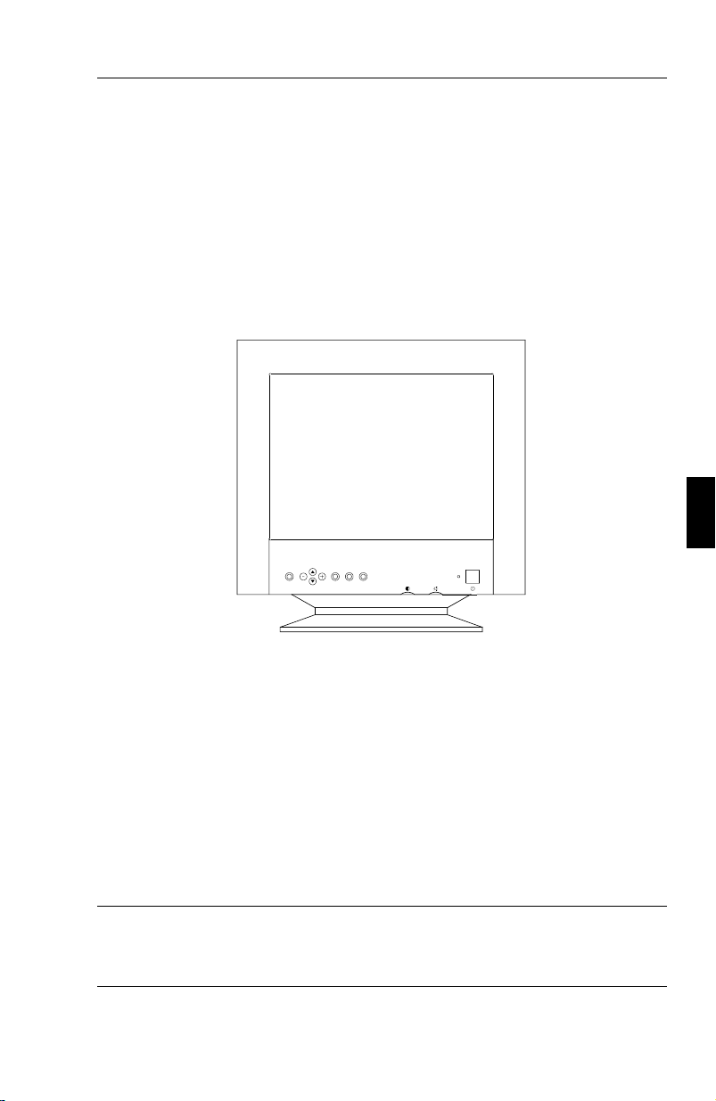
CONTENU DE L’EMBALLAGE F-7
CONTENU DE L’EMBALLAGE
L’illustration ci-dessous vous indique tous les éléments inclus dans
l’emballage de votre moniteur de la série XP. Conservez soigneusement
le carton d’origine et les matériaux d’emballage pour le transport de
votre moniteur.
1. Le moniteur couleur MultiSync XP17/XP21 (JC-1743UMB/R
/ JC-2143UMB/R) avec pied amovible et orientable.
2. Multicable
3. Cordon d’alimentation
4. Manuel d’utilisation
Disquettes du logiciel du canal de communication .
le pied du moniteur peut être enlevé. Des cales en plastiques ainsi
Note :
qu’un pied sont disponibles en option. Ils s’intègrent dans le bas du
cabinet du moniteur.

F-8 RECOMMANDATION D’UTILISATION
RECOMMANDATION D’UTILISATION
Lors de l’installation de votre moniteur couleur Multisync serie XP,
veuillez observez les précautions suivantes afin d’en tirer le maximum
de performance :
N’utilisez pas le moniteur dans un endroit directement exposé
–
au soleil.
Placez votre moniteur juste en dessous de l’axe de vision afin
–
de vous assurer le meilleur confort visuel
Laissez une aération suffisante autour du moniteur afin que la
–
chaleur qu’il dégage puisse se dissiper facilement.
Ne placez aucun objet lourd sur le cordon d’alimentation. Cela
–
risquerait de l’endommager et de provoquer une électrocution
ou un incendie.
Tenez le moniteur éloigné de transformateurs de puissance, de
–
moteurs électriques et d’autres systèmes susceptibles de générer
des champs magnétiques intenses.
N’utilisez pas le moniteur dans un endroit humide, sale ou
–
poussiéreux.
Si vous devez transporter votre moniteur, évitez toute
–
manipulation brutale.
–
Pour des raisons ergonomiques, nous vous recommandons
de régler la luminance de façon à faire disparaître le fond
de l’écran.
Pour ces mêmes raisons, nous vous recommandons de ne pas
–
travailler avec le contrôle de contraste réglé au maximum.
Pour des raisons ergonomiques nous vous recommandons
–
d’afficher les tailles et positions d’images présélectionnées.

RECOMMANDATION D’UTILISATION F-9
Pour ces mêmes raisons, nous vous recommandons d’utiliser les
–
préréglages d’origine (usine) de la couleur et de la distorsion
latérale.
–
Pour des raisons ergonomiques, nous vous recommandons
de travailler dans les bandes de fréquences de balayage
vertical : de 70 à 160 Hz .
Pour des raisons ergonomiques, nous vous recommandons de
–
ne pas travailler avec une image composée d’informations de
couleur bleue primaire sur fond noir. Cette combinaison de
couleurs est difficile à déceler et fatigue la vue à cause de son
faible contraste.
Pour débrancher le moniteur, enlevez le cordon secteur situé à
–
l’arrière du moniteur.
–
Nous vous recommandons d’utiliser le cordon
d’alimentation secteur livré avec le moniteur.
Cependant, si vous prévoyez d’en employer un autre, il doit être
–
de type H05 VVF avec le MultiSync XP17/XP21 ( sauf pour le
Royaume-Uni ).
Attention:
démagnétisation.
Pour nettoyer votre écran, utilisez un chiffon doux, non-pelucheux. Une
solution douce à base d’alcool ou un nettoyant pour vitre donne de bons
résultats.
Ne maintenez pas enfoncé plus de 10 secondes le bouton de

F-10 RECOMMANDATION D’UTILISATION
INSTALLATION RAPIDE
Le tableau suivant résume la méthode de connexion du moniteur
couleur MultiSync XP17 / XP21. Pour plus de détails reportez-vous aux
pages suivantes si vous possédez un ordinateur compatible IBM,
compatible, un Apple ou un autre système.
Utilisez-vous les entrées BNC
non
oui
Positionnez le commutateur BNC/DSU B s u r l a d r o i t e ( p o s i tion D-SUB)
Votre ordinateur est un Macin-
tosh
non
oui
Positionnez le commutateur SYNC sur
la position
ON
Reliez le cordon vidéo sur le port vidéo
de l’ordinateur puis sur le moniteur.
Reliez le cordon d’alimentation du
moniteur à la prise secteur et au moni-
teur
Mettez le moniteur sous tension. Met-
tez l’ordinateur sous tension.
Positionnez le commutateur BNC/D-
SUB s u r l a g a u c he (position BNC)
Si vous avez un Powerbook, un LC,
un AV, un PowerMac ou Quadra 605.
oui
non
Positionnez le commutateur
SYNC.sur la position
OFF
.
Si nécessaire, utilisez l’OSM pour
personnaliser votre affichage.
L’affichage est-il correct ?
oui
L’installation de votre moniteur cou-
leur MultiSync est terminée. A vous
de jouer
non
Reportez-vous à la section " Pro-
blèmes et solutions ".
oui
Problème résolu ?
non
Si votre problème demeure, n’hési-
tez pas à contacter votre revendeur
NEC.

CONNEXION F-11
CONNEXION
Connexion à un ordinateur personnel IBM ou compatible.
Les moniteurs couleur Multisync de la série XP sont compatibles avec
les ordinateurs IBM PC, XT, AT, 386, 486, Pentium, PS/2 et leurs
compatibles. 2 types de configuration peuvent être proposés sur PC.
1. le contrôleur vidéo est intégré sur la carte mère
2. le contrôleur vidéo est sur une carte graphique additionnelle.
Chacune des configurations dispose d’un connecteur vidéo. Si vous n’êtes
pas certain de quel connecteurs vidéo vous servir, consultez le manuel
d’utilisation de votre ordinateur ou de votre carte graphique. Pour
connecter votre moniteur à votre PC, suivez les instructions ci-dessous.
1. Eteignez votre ordinateur et votre moniteur.
2. Si besoin est, installez votre carte graphique. Pour plus
d’informations, reportez-vous au manuel d’utilisation de la carte.
3. Assurez-vous que le commutateur BNC/D-SUB sur la face
avant du moniteur (XP17/XP21) est sur la position D-SUB
(commutateur à droite).
4. Reliez l’extrémité mini D-SUB 15 broches de votre cordon
MultiCable au connecteur vidéo de votre ordinateur ( petit
connecteur).
5. Reliez l’extrémité D-SUB 15 broches de votre cordon MultiCable
au connecteur vidéo de votre moniteur ( grand connecteur).
6. Connectez le cordon d’alimentation secteur au moniteur
XP17/XP21 et à la prise secteur.
7. Mettez votre moniteur et votre ordinateur sous tension.
8. Votre installation est maintenant terminée.
En cas de problème, reportez-vous à la section " Problèmes et solutions ".

F-12 CONNEXION
Connexion à un ordinateur Apple.
Les moniteurs couleur MultiSync de la série XP sont compatibles avec
les ordinateurs de la famille Macintosh. 2 types de configuration
peuvent être proposés sur ces ordinateurs.
1. le contrôleur vidéo est intégré sur la carte mère
2. le contrôleur vidéo est sur une carte graphique optionnelle,
installée sur un connecteur Nu-Bus ou un slot PDS.
Si vous n’êtes pas certain du type de connecteur vidéo à utiliser, consultez le
manuel d’utilisation de votre ordinateur ou de votre carte graphique.
1. Eteignez votre ordinateur et votre moniteur.
2. Si besoin est, installez votre carte graphique. Pour plus
d’information, reportez-vous au manuel d’utilisation de la carte.
3. Vérifiez que le commutateur SYNC localisé à l’arrière du
moniteur, est sur la position OFF. Si votre ordinateur est un
Powerbook160, 165c, 180, 180c, Mac LC, Mac AV,
PowerMac ou un Mac .Quadra 605, assurez-vous que le
commutateur SYNC est sur la position ON.
4. Assurez-vous que le commutateur BNC/D-SUB situé sur la
face avant est sur la position D-SUB (à droite).
5. Reliez l’extrémité D-SUB 15 broches de votre cordon MultiCable
au connecteur vidéo de votre ordinateur ( grand connecteur).
6. Reliez l’extrémité mini D-SUB 15 broches de votre cordon
MultiCable au connecteur vidéo de votre moniteur ( petit
connecteur).
7. Connectez le cordon d’alimentation secteur à la prise secteur
et au moniteur XP17/XP21.
8. Mettez votre moniteur et votre ordinateur sous tension.
9. Votre installation est maintenant terminée.

CONNEXION F-13
Le Power Macintosh 6100/60 est livré avec un cordon Apple HD1-45.
Ce dernier est à utiliser conjointement avec un adaptateur spécifique (en
option) pour la connexion d’un moniteur de la serie XP
En cas de problème, reportez-vous à la section " Problèmes et
solutions".
Connexion à un autre système ou adaptateur vidéo.
Si votre système ou votre carte vidéo n’est pas compatible avec l’un des
standards vidéo pré-enregistrés (voir annexe) ou possède un brochage
différent (voir la table de brochage), reportez-vous aux instructions
ci-dessous pour vérifier que votre système est compatible avec votre
MultiSync XP17/XP21 ou contactez votre revendeur agréé NEC.
1. Eteignez votre moniteur et votre ordinateur.
2. Vérifiez le brochage de sortie de votre adaptateur vidéo.
3. Vérifiez les fréquences et les niveaux des signaux de sortie de
votre adaptateur vidéo.
4. Comparez au tableau de brochage et aux fréquences du
moniteur et assurez-vous que ceux-ci sont compatibles.
5. Connectez le cordon vidéo livré avec votre carte graphique
sur la prise vidéo du moniteur.
6. Connectez le cordon d’alimentation secteur au moniteur et à
la prise secteur.
7. Mettez votre moniteur et votre ordinateur sous tension.
8. Ajustez la taille et la position de l’image à votre convenance.
9. Votre installation est maintenant terminée.
En cas de problème, reportez-vous à la section " Problèmes et solutions " .

F-14 CONNEXION
Connexion à un ordinateur ou adaptateur vidéo en utilisant un cordon BNC.
Les moniteurs MultiSync couleurs de la série XP sont complémentaires
des cartes ou systèmes graphiques hautes résolutions. Pour reliez votre
moniteur à votre ordinateur, suivez les instructions ci-dessous :
1. Eteignez votre moniteur et votre ordinateur.
2. Si besoin est, installez votre carte graphique. Pour plus
d’information, reportez-vous au manuel d’utilisation de la carte.
3. Assurez-vous que le commutateur en face avant BNC/D-SUB
est sur la position BNC (position gauche).
4. Reliez le cordon vidéo, côté D-SUB à la carte graphique.
5. Reliez chaque prise BNC sur le moniteur en respectant les
indications suivantes :
La prise BNC rouge du cordon vidéo sur le connecteur BNC R
–
du moniteur. La prise BNC verte du cordon vidéo sur le
connecteur BNC G du moniteur. La prise BNC bleue du cordon
vidéo sur le connecteur BNC B du moniteur. Si vous possédez
un câble avec quatre prises BNC (composite Sync), celle-ci doit
être reliée sur le connecteur BNC marqué HS/CS. Si vous
possédez un câble avec cinq BNC, le connecteur BNC
véhiculant le signal de synchro vertical doit être relié sur le
connecteur BNC VS du moniteur
6. Connectez le cordon d’alimentation secteur au moniteur et à
la prise secteur.
7. Mettez votre moniteur et votre ordinateur sous tension.
8. Votre installation est maintenant terminée.
En cas de problème, reportez-vous à la section " Problèmes et solutions " .

CONNEXION F-15
Connexion à deux ordinateurs ou adaptateurs vidéo.
(ex : un PC et un Macintosh)
Les moniteurs MulitiSync de la série XP sont conçus pour supporter
simultanément la connexion de deux ordinateurs ou cartes graphiques.
Cette caractéristique vous permet d’utiliser un des deux systèmes et de
commuter très facilement d’un système à l’autre en utilisant le
commutateur BNC/D-SUB situé sur la face avant de votre moniteur.
Cette configuration nécessite impérativement l’emploi d’un cordon
vidéo BNC sur l’un des ordinateurs. Si vous n’en possédez pas,
contactez votre revendeur NEC.
Pour reliez votre moniteur aux deux ordinateurs, suivez les instructions
ci-dessous :
1. Suivez la procédure d’installation pour PC ou Mac donnée sur
les précedentes pages. Pour connecter le premier ordinateur,
utiliser le MultiCâble fourni avec le moniteur. L’installation
du premier moniteur est maintenant terminée.
2. Suivez la procédure d’installation de la précédente page se
rapportant à l’utilisation d’un cordon vidéo BNC pour
installer le second ordinateur.
3. Mettez votre moniteur et vos deux ordinateurs sous tension.
4. Votre installation est maintenant terminée.
5. Utilisez le commutateur BNC/D-SUB situé sur la face avant
du moniteur pour sélectionner l’ordinateur sur lequel vous
désirez travailler.
En cas de problème, reportez-vous à la section " Problèmes et solutions " .
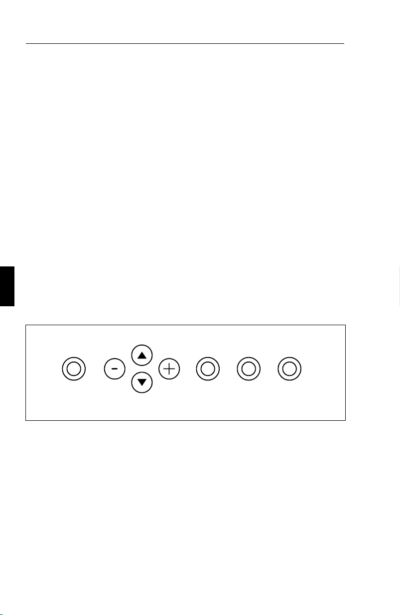
F-16 CONTRÔLE PAR L’OSM
CONTRÔLE PAR L’OSM
Le nouvel OSM de NEC (On Screen Manager) est le système le plus abouti
pour la configuration de votre moniteur Multisync. Les boutons sur la face
avant de votre moniteur vous permettent de vous déplacer dans des menus et
de procéder aux réglages. Lorsque vous choisissez un réglage, une icône
animée vous permet de visualiser immédiatement l’effet de vos réglages.
L’
Tous les réglages sont sauvegardés instantanément et automatiquement.
Vous pouvez annuler les modifications de réglage en cours en appuyant
sur la touche RESET.
Fonction des touches de contrôle en face avant du moniteur
touche EXIT:
dans un sous-menu : retour au menu précédent.
touche HAUT/BAS:
sélectionner un choix
touche +/- :
permet d’accéder aux réglages suivants :
OSM
taille et position
–
distorsion géométrique
–
contrôle des couleurs amélioré.
–
dans le menu principal : sortie de l’OSM.
permet de se déplacer dans le menu pour
dans le menu principal : pas d’action
dans un sous-menu : déplace la barre vers + ou - pour augmenter ou
diminuer les valeurs du réglage.
touche PROCEED :
menu sélectionné. ( pointé par la flèche )
dans le menu principal : permet d’entrer dans le

CONTRÔLE PAR L’OSM F-17
dans un sous-menu : déplace la flèche vers le bas pour sélectionner l’un
des choix.
touche RESET : rappel des paramètres d’origine (usine) du réglage
sélectionné.
dans le menu principal : rappel de tous les paramètres usine du
sous-menu sélectionné.
dans un sous-menu : rappel des paramètres du réglage sélectionné.
Fonctions des touches de contrôle autres que celles de l’OSM
touche de démagnétisation:
Elimine les champs magnétiques qui s’accumulent sur le masque de
l’écran. Ceux-ci altèrent la déviation des faisceaux d’électrons et
génèrent des impuretés de couleurs, de mise au point et de convergence.
Attention : Attendez au moins 20 minutes entre deux appuis sur la
touche de démagnétisation (en dehors des changements de mode).
Celle-ci n’en sera que plus efficace. N’appuyez pas plus de 10 secondes
de suite sur la touche de démagnétisation, pour éviter de réduire la durée
de vie du circuit de démagnétisation. La démagnétisation n’agit de toute
façon que durant les trois premières secondes qui suivent l’appui.
Commande de contraste
Règle la luminance de l’image par rapport à celle du fond. Il en résulte
une variation du contraste entre l’image et le fond.
Commande de luminance
Règle la luminance du fond de l’image.
Commutateur de mise sous tension
Met le moniteur sous ou hors tension.

F-18 Accès à L’OSM
Lorsque le moniteur est sous tension, l’indicateur lumineux de
consommation est allumé et indique le mode de fonctionnement. Chacun
des différents modes correspond à un niveau de consommation électrique.
Le voyant lumineux qui est situé au dessus du commutateur de mise
sous tension indique :
Etat Couleur
en fontionnement (on) verte
attente (standby) jaune
pause (suspend) orange
veille (off) orange
éteint pas de lumière
GRAPHIQUES DE L’OSM :
surbrillance : indique le menu ou le réglage sélectionné.
icône animée : représente l’action et le sens du réglage en cours.
barre de défilement indique le sens du réglage.
affichage numérique affiche un nombre pour s’en souvenir, le noter ou
le comparer à une valeur spécifique.
Accès à L’OSM
- Appuyez sur une des touches de contrôle +, -, flèche en Bas, flèche en
Haut ou sur la touche PROCEED
Sortie de l’OSM
depuis le menu principal : appuyer sur la touche EXIT.
depuis un sous-menu : appuyer 2 fois sur la touche EXIT

LES MENUS DE l’OSM F-19
LES MENUS DE l’OSM
Menu principal :
Le menu principal de l’OSM vous donne une vue sur l’ensemble des
contrôles disponibles. Les flèches dans les coins droits supérieurs ou
inférieurs vous indiquent que d’autres choix vous sont proposés. Utiliser
les touches
haut / bas
pour balayer l’ensemble des choix disponibles.
ON SCREEN MANAGER
Position
Taille
Contrôle de Couleur
Géométrie Simple
Géométrie Fine
Réglage de pureté
Position de l’OSM
Lorsque vous vous trouvez dans le menu principal de l’OSM, les
touches sur la face avant ont les actions suivantes :
sortie de l’OSM
exit :
touches haut/bas:
déplace le curseur en haut ou en bas pour
sélectionner un choix.
touches +/- :
proceed :
reset :
l’appui sur
Note:
pas d’action.
actionne le choix sélectionné.
rappel de tous les paramètres d’origine du menu en surbrillance.
dans le menu "Contrôle de Couleur" annule tous
reset
vos réglages personnels de couleurs.
La touche
n’a pas d’effet dans les menus "Extinction de l’OSM" et
reset
"Langage"

F-20 LES MENUS DE l’OSM
Menu POSITION
Position
Haut
Gauche Droite
Bas
Haut/Bas : déplace l’image verticalement vers le haut ou vers le bas
Gauche/Droite : déplace l’image horizontalement vers la gauche ou
vers la droite
Menu TAILLE
Taille
Grand
Etroit Large
Petit
Grand/Petit : agit sur la dimension verticale de l’image
Etroit/Large : agit sur la dimension horizontale de l’image
Dans les menus Position ou Taille, les touches du panneau de contrôle
en face avant ont les actions suivantes:
exit : retour au menu principal.
touches haut/bas: agit sur la dimension ou la position verticale de
l’image.
touches +/- : agit sur la dimension ou la position horizontale de l’image.
proceed : pas d’action.
reset : rappel des paramètres d’origine du réglage en cours.
Note : Une fenêtre d’alerte vous permettra de confirmer le rappel des
réglages usine où d’annuler ce rappel.

LES MENUS DE l’OSM F-21
Menu CONTRÔLE DE COULEUR :
Contrôle de Couleur
Préréglage:
1 2 3 4 5
Gain Coul:
Rouge
Vert
Bleu
Préréglage
Sélection d’un des préréglages de couleur.
La barre est alors remplacée par la couleur initiale choisie (de 1 à 5).
Chaque couleur est réglée d’origine en usine à une certaine température
exprimée en degrés Kelvin. Si un préréglage est modifié, le message
"Au choix " sera affiché à la place de l’indication en degrés Kelvin.
Gain des couleurs:
Augmente ou diminue la valeur des couleurs Rouge, Vert ou Bleu en
fonction de celle qui a été sélectionnée. Le changement du réglage de la
couleur apparait à l’écran et le sens "+" ou "-" est visualisé par la barre
de couleur. Une couleur est toujours utilisée comme couleur de
référence et ne changera pas lors de vos réglages. Vos réglages sont
sauvegardés instantanément et automatiquement.
Lorsque vous êtes dans le menu de "Contrôle de Couleur", les touches
en face avant du moniteur ont les actions suivantes :
exit : retour au menu principal.
touches haut/bas: déplacement dans le menu pour sélectionner un choix.
touches +/- : permet d’augmenter où de diminuer les valeurs du choix
sélectionné.( de 1 à 5).
proceed: déplace la fléche vers le bas pour sélectionner l’un des choix
reset : rappel des paramètres d’origine du réglage sélectionné.
Note : Une fenêtre d’alerte vous permettra de confirmer le rappel des
réglages usine où d’annuler ce rappel.

F-22 LES MENUS DE l’OSM
Menu GÉOMÉTRIE SIMPLE
Géométrie Simple
Côtés:
Int/Ext
Gau/Droit
Pente
Alignement
Rotation
Ces réglages de géométrie de base vous permettent de régler
l’inclinaison ou l’angle des côtes.
Côtés Int/Ext: (distorsion de coussin ) augmente ou diminue la
curvature des flancs de l’image vers l’intérieur ou vers l’extérieur.
Côtés Gau/Droit: (balance de la distorsion de coussin) augmente ou
diminue la curvature des flancs de l’image vers la gauche ou vers la droite.
Côtés Pente : (distortion de parallèlogramme) augmente ou diminue la
pente des flancs vers la gauche ou vers la droite.
Côtés Alignement : (distorsion de trapèze) augmente ou diminue le
haut de l’image pour le faire coïncider avec le bas.
Rotation : (rotation de balayage) permet de faire effectuer une rotation
de l’image dans un sens ou dans l’autre sens.
Lorsque vous êtes dans le menu de Géométrie Simple, les touches en
face avant du moniteur ont les actions suivantes :
exit : retour au menu principal
touches haut /bas: déplacement dans le menu pour sélectionner un choix.
touches +/- : permet d’augmenter où de diminuer les valeurs du choix
sélectionné.
proceed: déplace la fléche vers le bas pour sélectionner l’un des choix
reset : rappel des paramètres d’origine du réglage sélectionné.
Note : Une fenêtre d’alerte vous permettra de confirmer le rappel des
réglages usine où d’annuler ce rappel.

LES MENUS DE l’OSM F-23
Menu GÉOMÉTRIE FINE
Géométrie Fine
Haut:
Int/Ext
Gau/Droit
Bas:
Int/Ext
Gau/Droit
Le contrôle de géométrie fine vous permet de régler les coins de
l’image.
Haut Int/Ext: Permet de régler la distorsion des angles supérieurs.
Haut Gau/Droit : Permet de régler la balance des angles supérieurs.
Bas Int/Ext: Permet de régler la distorsion des angles inférieurs.
Bas Gau/Droit: (Distorsion effet de coussin) Permet de régler la
balance des angles supérieurs.
Lorsque vous êtes dans le menu de Géométrie Fine, les touches en face
avant du moniteur ont les actions suivantes :
exit : retour au menu principal.
touches haut/bas: déplacement dans le menu pour sélectionner un choix.
touches +/- : permet d’augmenter où de diminuer la valeur sélectionnée.
proceed: déplace la fléche vers le bas pour sélectionner l’un des choix
reset : rappel des paramètres d’origine du réglage sélectionné.
Note : Une fenêtre d’alerte vous permettra de confirmer le rappel du
réglage d’origine ou d’annuler ce rappel.

F-24 LES MENUS DE l’OSM
Menu RÉGLAGE DE PURETÉ
Le moniteur Multisync XP21 de grande taille offre un contrôle
supplémentaire, celui de la pureté de l’image appelé "Réglage de
pureté". Ce contrôle élimine les impuretés de la couleur, qui peuvent
apparaître dans les coins de l’écran, consécutives aux effets du champ
magnétique terrestre dans l’hémisphère nord. Ce contrôle est
automatiquement actionné par l’appui sur la touche PROCEED
Réglage de pureté
Appuyer:
PROCEED - Démarrage
EXIT - Abandon
Menu POSITION DE L’OSM
Position de l’OSM
Haut
Gauche Droite
Bas
Vous pouvez choisir l’endroit où le menu de l’OSM sera affiché sur
votre écran :
Le réglage vous permet de positionner manuellement l’affichage du
menu de l’OSM :
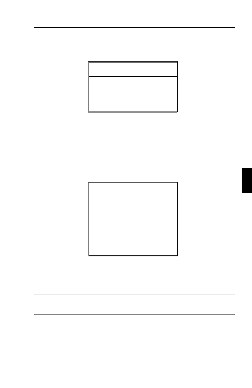
LES MENUS DE l’OSM F-25
Menu EXTINCTION DE L’OSM
Extinction de l’OSM
Secondes:
10 20 30 60 120
Le menu de l’OSM restera actif aussi longtemps que vous l’utiliserez.
Dans le menu d’extinction de l’OSM, vous pouvez choisir le temps que
mettra l’affichage pour s’éteindre après le dernière pression sur une
touche.
Les temps préréglés sont de 10, 20, 30, 60 et 120 secondes.
Menu MODE D’AFFICHAGE
Mode d’affichage
Mode:
Fréq.H.:
Fréq.V.:
Pol.H.:
Pol.V.:
Le menu du mode affichage vous renseigne sur la définition affichée et
les données techniques telles que :
les fréquences horizontale et verticale.
Note : si le mode affichage indique le symbole "(!)", la fonction reset
pour le menu Taille et Position n’a pas d’effet.
Menu LANGAGE
les menus de l’OSM sont disponibles en 6 langues.
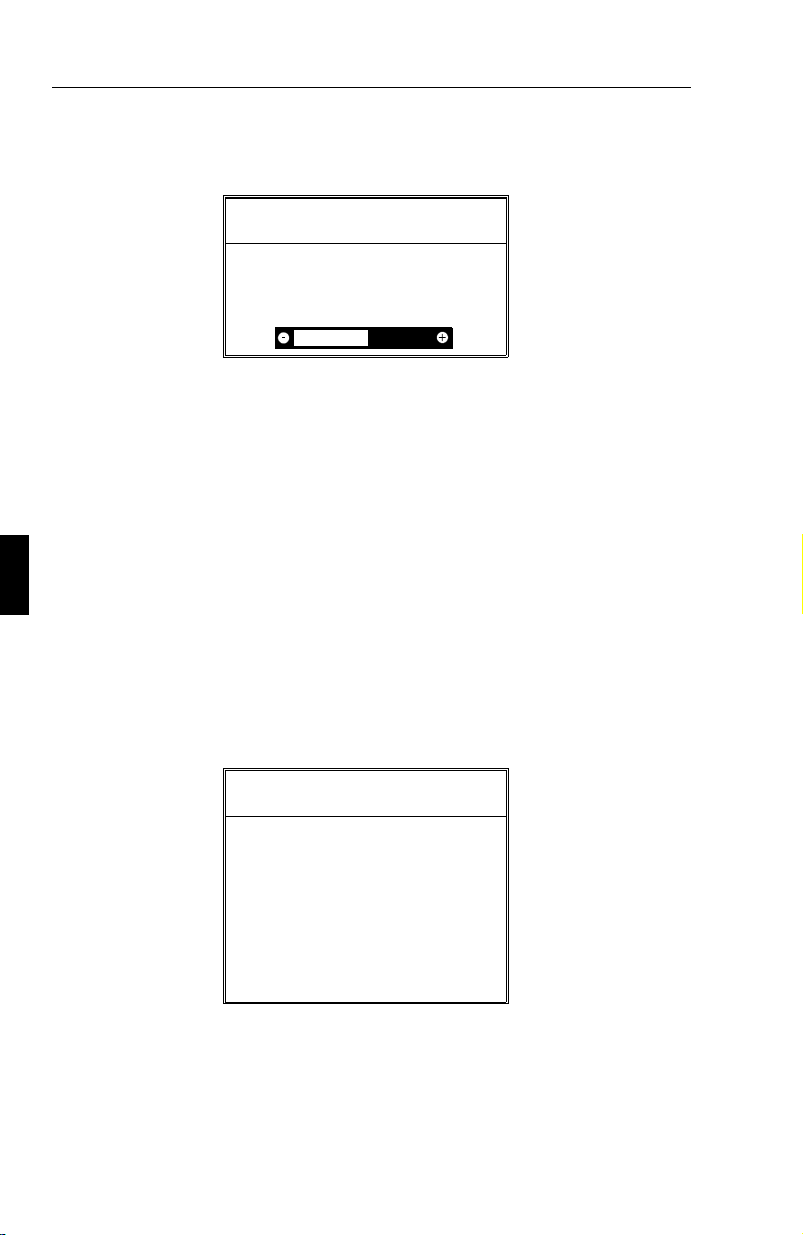
F-26 LES MENUS DE l’OSM
Menu LINÉARITÉ VERTICALE
Linéarité Verticale
Centre
Bas/Haut
Le contrôle de linéarité verticale vous permet de régler les espaces dans
le haut et le bas de l’écran pour qu’ils soient identiques. Le but de ce
réglage est de s’assurer qu’un cercle de 2 cm de diamètre soit un vrai
cercle de 2 cm de diamètre quel que soit l’endroit de l’écran où il est
affiché (Taille identique du dessin sur l’intégralité de l’aire d’affichage).
La procédure à suivre pour régler la linéarité verticale est celle décrite
dans le menu de contrôle de linéarité verticale :
Dessinez à l’écran des lignes horizontales équidistantes à l’aide d’un
logiciel de dessin possédant une règle.
En utilisant le réglage Centre, vous ajustez l’espacement entre les lignes
centrales et en utilisant le réglage Bas/Haut, vous ajustez l’espace entre
les lignes du haut et du bas du dessin.
Menu PRÉRÉGLAGE USINE
ATTENTION
A PROPOS DU RESET
TOUS REGLAGES
Appuyer :
RESET - Démarrage
EXIT - Abandon
Le menu Préréglage d’usine vous permet de remettre tous les réglages
de l’OSM à leur état d’origine. La fenêtre d’ alarme ci-dessous apparaît
pour vous demander de confirmer si vous voulez vraiment TOUS vos
réglages. Les réglages individuels peuvent être annulés en mettant en
surbrillance le contrôle à annuler, puis par l’appui sur la touche reset.

LES MENUS DE l’OSM F-27
Auto-test
pour vous assurez que votre moniteur fonctionne correctement, vous
pouvez activer la fonction AUTO-TEST de la façon suivante :
Éteindre votre moniteur et votre ordinateur. Déconnectez le cordon
vidéo de votre ordinateur ou votre carte vidéo. Mettez le moniteur sous
tension. Tout en maintenant la touche EXIT enfoncée, appuyez sur la
touche PROCEED, l’image suivante s’affiche alors à l’écran. Si vous
n’appuyez pas de vous-même sur la touche EXIT pour annuler cette
fonction l’image redeviendra noire au bout de 20 secondes.
Self Test Menu
EXIT - Abandon
Problèmes et solutions
Avant d’appeler votre revendeur agréé NEC, veuillez vérifier les points
suivants :Si vous utilisez un sous-système vidéo non compatible IBM
AT ou Apple de la famille Macintosh, assurez-vous que les fréquences
et durées des signaux utilisés, ainsi que le brochage du connecteur vidéo
soit en accord avec les caractéristiques décrites en annexe A et B.
Incident Vérifiez les points suivants
Pas d’image. Commutateurs de mise sous tension du
moniteur et de l’ordinateur. Cordon vidéo du
moniteur. Connexion du sous-système vidéo.
Le voyant lumineux de mise
sous tension est éteint ou de
couleur orange ou jaune.
L’image présente des
impuretés de couleurs
Commutateur de mise sous tension. Cordon
d’alimentation. Assurez-vous que
l’ordinateur ne soit pas dans un mode
d’économie d’énergie (appuyez sur une
touche du clavier ou déplacez la souris).
Pressez le bouton de démagnétisation. Ne
rester jamais en appui continu ce bouton.

F-28 LES MENUS DE l’OSM
L’image défile ou est instable Le cordon de connexion peut être mal
enfiché à l’ordinateur. Vérifiez le cablage et
la compatibilité des modes vidéo entre le
moniteur et votre carte graphique.Enfichage
incorrect de la carte additionnelle dans le
connecteur de l’ordinateur. Vérifiez que le
commutateur SYNC est sur la position
adéquate.
L’image est floue. Réglez le contraste et la luminance.
Appuyez sur le bouton de démagnétisation.
Un intervalle de 20 minutes est nécessaire
avant de presser à nouveau le bouton de
démagnétisation.
L’image est instable. Déplacez, si nécessaire, les appareils
électriques qui se trouvent à proximité du
moniteur
L’image est déformée vers
l’intérieur ou vers l’extérieur.
L’image affichée n’est pas
centrée, trop grande, trop
petite.
Pas de couleur verte (si vous
utilisez les connecteurs BNC
L’image a une teinte verte ou
la trame de l’image ne peutêtre éteinte.
Réglez le contrôle de distorsion latérale en
utilisant l’OSM.Entrez dans le menu de
géométrie. Si possible, positionnez le
moniteur face à l’Est
Réglez la position horizontale et verticale, la
taille horizontale et verticale en utilisant
l‘OSM
Verifez le cordon BNC, Il y a peut être une
inversion sur les connecteurs G et HS/CS
Vérifiez que le commutateur SYNC est sur
la position adéquate.
Déconnectez la prise BNC qui se trouve sur
l‘entrée HS/CS du moniteur

Caractéristiques techniques F-29
Couleurs incorrectes ou
luminance trop forte
Vérifiez la position du commutateur
SYNC.Si vous utilisez un Mac II, Quadra ou
compatible ( sauf Mac LC ) avec la synchro
sur le vert, le commutateur SYNC doit être
positionné sur OFFQuand vous utilisez un
ordinateur ou une carte vidéo avec les
signaux de synchronisation séparés
(VGA,SVGA, 8514/A, XGA équipé d’une
prise mini D-SUB 15 sur le moniteur et un
signal de composite synchro, ou un
Macintosh LC, AV’s, Powerbooks ou
Powermac ou Quadra 605 : le commutateur
SYNC doit être sur la position ON.
Caractéristiques techniques
Tube image Tube à rayon cathodique plat de 17/21 pouces de
diagonale offrant une aire d’affichage de 41/51 cm.
Iriplets de points de luminophores au pas de 0,28 mm,
matrice noire Phosphore à persistance moyenne, dalle
sombre revêtement antistatique et traitement OptiClear.
Signaux d’entrée Vidéo : analogique 0,7 Vcc, 75 ohms, positive
Synchros : synchronisations niveaux TTL séparées,
sync. horizontale positive/négative
sync. verticale positive/négative
sync. composite, niveau TTL
positive/négative
sync. sur la vidéo
verte
Couleurs affichées Entrées analogiques : palette de couleurs illimitée
Plage
de synchronisation
Plage
de synchronisation
Horizontale : XP17 de 31 à 82 kHz
XP21 de 31 à 89 kHz (automatiquement)
Verticale : de 55 à 160 Hz (automatiquement)
(0,3 Vcc ) négative

F-30 Caractéristiques techniques
Définition maximale Horizontale :
Verticale :
Bande passante
vidéo
Aire d’affichage
réglage usine
Aire d’affichage
balayage étendu
Horizontale : XP17 : 306 mm
Verticale : XP17 : 230 mm
Horizontale : XP17 : 316 mm
Verticale : XP17 : 237 mm
XP17 1280
XP21 1600 (en mode non entrelacé)
XP17 1024
XP21 1200 (en mode non entrelacé)
XP17 140 MHz BNC input
XP21 190 MHz BNC input
XP21 : 390 mm
(l’aire d’affichage utile dépend
des fréquences vidéo)
XP21 : 293 mm
(l’aire d’affichage utile dépend
des fréquences vidéo)
XP21 : 402mm
(l’aire d’affichage utile dépend
des fréquences vidéo)
XP21 : 301 mm
(l’aire d’affichage utile dépend
des fréquences vidéo)
Tension nominale 220-240 Vac, 50/60 Hz.
Courant nominal XP17 1,3 A
XP21 1,8 A
Dimensions XP17 417,0 mm (L) x 433,3 mm (H) x 489,2 mm (P)
XP21 512 mm (L) x 529 mm (H) x 572 mm (P)
Poids XP17 23,5 kg
XP21 35,8 kg
Conditions
d’environnement
Fonctionneme
nt :
Stockage :
température de 0 °C à +35 °C
humidité de 30% à 80%
température de -20 °C à +60 °C
humidité de 10% à 90%
Les caractéristiques techniques peuvent être modifiées sans préavis.

Español

Introducción S-1
Introducción
Le felicitamos por la adquisición de su monitor color MultiSync
XP17/XP21.
Los monitores MultiSync XP17/XP21 incorporan la tecnología "Plug
and Play" de Microsoft, las características de ErgoDesign, los menús
"On Screen Manager" (OSM), así como todas las características únicas
que usted espera encontrar en los monitores MultiSync.
La tecnología MultiSync proporciona compatibilidad automática con
múltiples plataformas y con un amplio abanico de estándares gráficos,
permitiéndole mejorar la resolución de su sistema gráfico sin necesidad
de cambiar de monitor.
Los monitores MultiSync XP17/XP21 siguen estrictamente las líneas
maestras de ErgoDesign. El objetivo de ErgoDesign es optimizar la
productividad y el confort del usuario. ErgoDesign cumple las estrictas
normas europeas de bajo consumo y de reducción de emisiones.
Además, nuestros monitores han sido diseñados pensando en su
posterior reciclaje.
Sumario de Características
"Plug and Play"
Windows 95, para proporcionar conexiones de periféricos
automáticamente sin confusiones ni pérdida de tiempo en las
configuraciones. NEC ha codesarrollado junto con Microsoft la
tecnología "Plug and Play" para monitores. Esta tecnología permite a su
sistema identificar y configurar automáticamente el monitor conectado.
Los monitores de la serie XP, informan al sistema del tipo de monitor y
de sus capacidades. NEC junto con Microsoft le proporcionan la
instalación y configuración más simple en la actualidad.
Access.bus
Proporciona una comunicación bidireccional entre dispositivos, tales
como monitores, ratones, teclados y el sistema. El sistema puede
aprender de los dispositivos conectados y los dispositivos pueden recibir
y ejecutar instrucciones. Los dispositivos Access.bus pueden ser
es la nueva solución de Microsoft implementada en
es el nuevo estándar de comunicación entre dispositivos.

S-2 Introducción
conectados a cualquier conector ACCESS.bus en cualquier momento,
tanto si el sistema está encendido o apagado.
Access.bus incluye todas las capacidades de "Plug and Play", y además
le permite a su sistema autoconfigurar a su monitor de la serie XP con
las mejores prestaciones posibles. Usted puede estar seguro de que su
monitor adopta la más alta resolución y refresco que su sistema de video
puede visualizar. El monitor puede también ajustarse a través de
aplicaciones software o del teclado. De esta manera, usted puede
aumentar la funcionalidad de su monitor de la serie XP.
El sistema de cableado entre el monitor y el sistema, se reduce
considerablemente gracias al Access.bus. Los monitores de la serie XP
incluyen un conector para dispositivos Access.bus como ratones y teclados.
Usted incrementa considerablemente la flexibilidad y posibilidades de
conexión de su sistema a cualquier periférico, gracias al Access.bus.
Los controles OSM (On-Screen-Manager) se extienden utilizando el
software Image Manager Software. Le permite particularizar y
almacenar un ilimitado número de configuraciones. Usted puede ahora
almacenar no sólo una resolución, sino también un número de colores.
El sistema de manejo del color Colorific Color Enhancement le ayuda a
que los colores de su sistema de impresión coincidan con los que ve en su
pantalla, gracias a la tecnología de gestión de color de Kodak en el entorno
Windows o a la utilidad Apple ColorSync en los ordenadores Macintosh.
El software DPI-On-The-Fly para ordenadores Macintosh, le permite
utilizar varias resoluciones con su ordenador. De esta manera, usted
puede aumentar su resolución, por ejemplo a 1024x768, para tener más
información en la pantalla, y cambiar a una resolución más baja como
640x480 para aumentar la velocidad de su sistema o aumentar el
número de colores visualizable.
Por favor, consulte las instrucciones que acompañan al software para su
instalación.
El sistema Intelligent Power Manager (IPM) sigue las guías maestras
de la norma EPA del gobierno de los Estados Unidos, así como la
norma europea Nutek. El sistema de ahorro de energía IPM aumenta la
vida del monitor y ahorra energía y costes innecesarios mediante la
disminución de energía cuando no se detecta actividad por el sistema.
La especificación Nutek 803299 obliga a consumir menos de 30 W en

Test de Emisiones S-3
espera- standby- y 8 W en modo de suspesión. En el estado de máximo
ahorro de energía, los monitores MultiSync XP consumen
aproximadamente un 10% del consumo en funcionamiento completo.
Esta innovación permiteahorrar hasta un 90% de energía, prolongando
la vida del monitor, protegiendo el medio ambiente, reduciendo las
emisiones y los costes en el entorno de trabajo.
Nota: Esta utilidad-IPM- necesita para activarse que su sistema de video
soporte esta característica de acuerdo a la norma DPMS de VESA.
El menú OSM (On Screen Manager) facilita al usuario el sistema de
control digital del monitor. Una presión en los controles frontales permite
visualizar los menús de pantalla (OSM). Los menús e iconos que aparecen
en su pantalla le explican fácilmente cómo funcionan los controles.
El Control de Color le permite ajustar los colores de pantalla exactamente a
sus preferencias. Esto elimina frustaciones y confusiones. El Sistema de
Color: "Colorific Color Enhancement" le pemite ajustar los colores de su
pantalla a los de su sistema de impresión, mediante la incorporación de la
tecnología Kodak Color Management System en Microsoft Windows y la
utilidad Apple ColorSync en ordenadores Apple.
El tratamiento OptiClear, en la superficie del tubo de los monitores XP,
reduce los reflejos de la iluminación ambiente, sin sacrificar ni el foco
ni el brillo de la imagen.
El tamaño de punto de 0.28 mm y una máscara del tipo Invar
Shadow Mask junto con un Foco Dinámico (sólo XP17 y XP21),
aumenta la claridad y detalle de la imagen. Una buena definición de la
imagen permite que sus ojos capten la información que se muestra en la
pantalla con mayor facilidad.
El control Global Sinc del MultiSync XP21 minimiza la influencia del
campo magnético terrestre en las prestaciones del monitor.
Test de Emisiones
ErgoDesign incorpora reducción de emisiones debidas a campos
electrostáticos y electromagnéticos. Los monitores de NEC cumplen
estrictamente las recomendaciones de TCO y SWEDAC (Instituto Suec o de
 Loading...