


English-1
English
Important Information .......................................................................................................................... English-2
Safety Precautions, Maintenance, & Recommended Use................................................................ English-3
Contents .................................................................................................................................................... English-4
Attaching LCD Options ............................................................................................................................ English-5
Parts Name and Functions
Control Panel ............................................................................................................................ English-6
Terminal Panel .......................................................................................................................... English-7
Wireless Remote Control ........................................................................................................ English-8
Operating Range for the Remote Control .......................................................................... English-9
Handling the Remote Control ............................................................................................... English-9
Setup Procedure ...................................................................................................................................... English-10
Connections
Wiring Diagram..................................................................................................................... English-12
Connecting the LCD Monitor to a PC ............................................................................... English-13
Connecting to a Macintosh Computer............................................................................. English-14
Connecting to a Computer with a Digital Output ......................................................... English-15
Connecting to a DVD Player ............................................................................................... English-16
Connecting to a Stereo Amplifier .................................................................................... English-17
Basic Operation
Power On and Off modes ......................................................................................................... English-18
Power Indicator........................................................................................................................ English-19
When Using Power Management Function.......................................................................... English-19
Selecting a Video Source ........................................................................................................ English-19
Picture Size ............................................................................................................................... English-19
Picture Mode ............................................................................................................................. English-19
OSM Information ...................................................................................................................... English-19
OSM (On-Screen-Manager) Controls ................................................................................................... English-20
Picture ........................................................................................................................................ English-20
Screen......................................................................................................................................... English-21
Audio ........................................................................................................................................... English-22
Configuration 1 ......................................................................................................................... English-23
Configuration 2 ........................................................................................................................ English-24
Advanced Option ...................................................................................................................... English-26
NOTE ............................................................................................................................................ English-28
Using the LCD with a Personal Computer (PC) .................................................................................. English-29
Features ..................................................................................................................................................... English-32
Troubleshooting ....................................................................................................................................... English-33
References ................................................................................................................................................ English-34
Specifications ........................................................................................................................................... English-35
Pin Assignment ......................................................................................................................................... English-37
Limited Warranty..................................................................................................................................... English-38
Index
English-2
Important Information
Canadian Department of Communications Compliance Statement
DOC: This Class B digital apparatus meets all requirements of the Canadian Interference-Causing Equipment Regulations.
C-UL: Bears the C-UL Mark and is in compliance with Canadian Safety Regulations according to
CAN/CSA C22.2 No.
60950-1.
FCC Information
1.
Use the attached specified cables with the MultiSync® LCD4010™ (L404G6)
/ MultiSync LCD4610 (L464G7)
color monitor so
as not to interfere with radio and television reception.
(1)
Please use the supplied power cord or equivalent to ensure FCC compliance.
(2) Please use the supplied shielded video signal cable, 15-pin mini D-SUB to 15-pin mini D-SUB.
(3) Please attach the ferrite cores on the Audio Cable. Please see page 12 of this manual.
2.
This equipment has been tested and found to comply with the limits for a Class B digital device, pursuant to part 15 of the FCC
Rules. These limits are designed to provide reasonable protection against harmful interference in a residential installation. This
equipment generates, uses, and can radiate radio frequency energy, and, if not installed and used in accordance with the
instructions, may cause harmful interference to radio communications. However, there is no guarantee that interference will
not occur in a particular installation. If this equipment does cause harmful interference to radio or television reception, which
can be determined by turning the equipment off and on, the user is encouraged to try to correct the interference by one or more
of the following measures:
• Reorient or relocate the receiving antenna.
• Increase the separation between the equipment and receiver.
• Connect the equipment into an outlet on a circuit different from that to which the receiver is connected.
• Consult your dealer or an experienced radio/TV technician for help.
If necessary, the user should contact the dealer or an experienced radio/television technician for additional suggestions. The
user may find the following booklet, prepared by the Federal Communications Commission, helpful: ”How to Identify and Resolve
Radio-TV Interference Problems.“ This booklet is available from the U.S. Government Printing Office, Washington, D.C., 20402,
Stock No. 004-000-00345-4.
CAUTION: TO REDUCE THE RISK OF ELECTRIC SHOCK, MAKE SURE POWER CORD IS UNPLUGGED FROM WALL SOCKET. TO FULLY
DISENGAGE THE POWER TO THE UNIT, PLEASE DISCONNECT THE POWER CORD FROM THE AC OUTLET. DO NOT REMOVE
COVER (OR BACK). NO USER SERVICEABLE PARTS INSIDE. REFER SERVICING TO QUALIFIED SERVICE PERSONNEL.
This symbol warns user that uninsulated voltage within the unit may have sufficient magnitude to cause electric shock. Therefore, it is
dangerous to make any kind of contact with any part inside this unit.
This symbol alerts the user that important literature concerning the operation and maintenance of this unit has been included. Therefore,
it should be read carefully in order to avoid any problems.
WARNING
CAUTION
TO PREVENT FIRE OR SHOCK HAZARDS, DO NOT EXPOSE THIS UNIT TO RAIN OR MOISTURE. ALSO, DO NOT USE THIS UNIT'S
POLARIZED PLUG WITH AN EXTENSION CORD RECEPTACLE OR OTHER OUTLETS UNLESS THE PRONGS CAN BE FULLY INSERTED.
REFRAIN FROM OPENING THE CABINET AS THERE ARE HIGH VOLTAGE COMPONENTS INSIDE. REFER SERVICING TO QUALIFIED
SERVICE PERSONNEL.

English-3
English
CAUTION
Immediately unplug your monitor from the wall outlet and refer
servicing to qualified service personnel under the following
conditions:
• When the power supply cord or plug is damaged.
• If liquid has been spilled, or objects have fallen into the
monitor.
• If the monitor has been exposed to rain or water.
• If the monitor has been dropped or the cabinet damaged.
• If the monitor does not operate normally by following operating
instructions.
Recommended Use
CAUTION
CORRECT PLACEMENT AND ADJUSTMENT OF THE MONITOR
CAN REDUCE EYE, SHOULDER AND NECK FATIGUE. CHECK THE
FOLLOWING WHEN YOU POSITION THE MONITOR:
• For optimum performance, allow 20 minutes for warm-up.
• Rest your eyes periodically by focusing on an object at least 5
feet away. Blink often.
• Position the monitor at a 90˚ angle to windows and other light
sources to minimize glare and reflections.
• Clean the LCD monitor surface with a lint-free, nonabrasive cloth.
Avoid using any cleaning solution or glass cleaner.
• Adjust the monitor’s brightness and contrast controls to enhance
readability.
•Avoid displaying fixed patterns on the monitor for long periods
of time to avoid image persistence (afterimage effects).
• Get regular eye checkups.
• The backlight lamp contains mercury. Please handle it appropriately in case of disposal.
Ergonomics
To realize the maximum ergonomic benefits, we recommend the
following:
• Use the preset Size and Position controls with standard
signals.
• Use the preset Color Setting.
• Use non-interlaced signals.
• Do not use primary color blue on a dark background, as it is
difficult to see and may produce eye fatigue due to insufficient
contrast.
For more detailed information on setting up a healthy work
environment, write the American National Standard for Human Factors Engineering of Visual Display Terminal Workstations – ANSIHFS Standard No. 100-1988 – The Human Factors Society, Inc.
P.O. Box 1369, Santa Monica, California 90406.
Safety Precautions and Maintenance
FOR OPTIMUM PERFORMANCE, PLEASE NOTE THE FOLLOWING
WHEN SETTING UP AND USING THE MultiSync
®
LCD4010™ /
MultiSync
®
LCD 4610LCD COLOR MONITOR:
• DO NOT OPEN THE MONITOR. There are no user serviceable
parts inside and opening or removing covers may expose you
to dangerous shock hazards or other risks. Refer all servicing to
qualified service personnel.
• Do not spill any liquids into the cabinet or use your monitor
near water.
• Do not insert objects of any kind into the cabinet slots, as they
may touch dangerous voltage points, which can be harmful or
fatal or may cause electric shock, fire or equipment failure.
• Do not place any heavy objects on the power cord. Damage to
the cord may cause shock or fire.
• Do not place this product on a sloping or unstable cart, stand or
table, as the monitor may fall, causing serious damage to the
monitor.
• When operating the MultiSync LCD4010 / MultiSync LCD4610
monitor with its AC 125-240V power supply, use a power supply cord that matches the power supply voltage of the AC power
outlet being used. The power supply cord you use must have
been approved by and comply with the safety standards of your
country. (Type H05VV-F 3G 1mm
2
should be used in Europe)
• In the UK, use a BS-approved power cord with molded plug
having a black (13A) fuse installed for use with this monitor. If a
power cord is not supplied with this monitor, please contact your
supplier.
• Do not place any objects onto the monitor and do not use the
monitor outdoors.
• The inside of the fluorescent tube located within the LCD
monitor contains mercury. Please follow the bylaws or rules of
your municipality to dispose of the tube properly.
• Do not bend, crimp or otherwise damage the power cord.
• Do not use monitor in high temperature, humid, dusty, or oily
areas.
• If glass is broken, handle with care.
• Do not cover vent on monitor.
• If monitor or glass is broken, do not come in contact with the
liquid crystal. Handle broken glass with care.
• Allow adequate ventilation around the monitor so that heat can
properly dissipate. Do not block ventilated openings or place
the monitor near a radiator or other heat sources. Do not put
anything on top of monitor.
• The power cable connector is the primary means of detaching
the system from the power supply. The monitor should be installed close to a power outlet which is easily accessible.
• Handle with care when transporting. Save packaging for
transporting.
• Keep the vent holes on the back of the LCD clean of dirt and
dust. It is recommended to wipe holes with a soft cloth a
minimum of once per year.
• If using the cooling fan continuously, it’s recommended to wipe
vent holes a minimum of once a month
Safety Precautions, Maintenance & Recommended Use
English-4
MultiSync® LCD4010™
MultiSync
®
LCD4610™
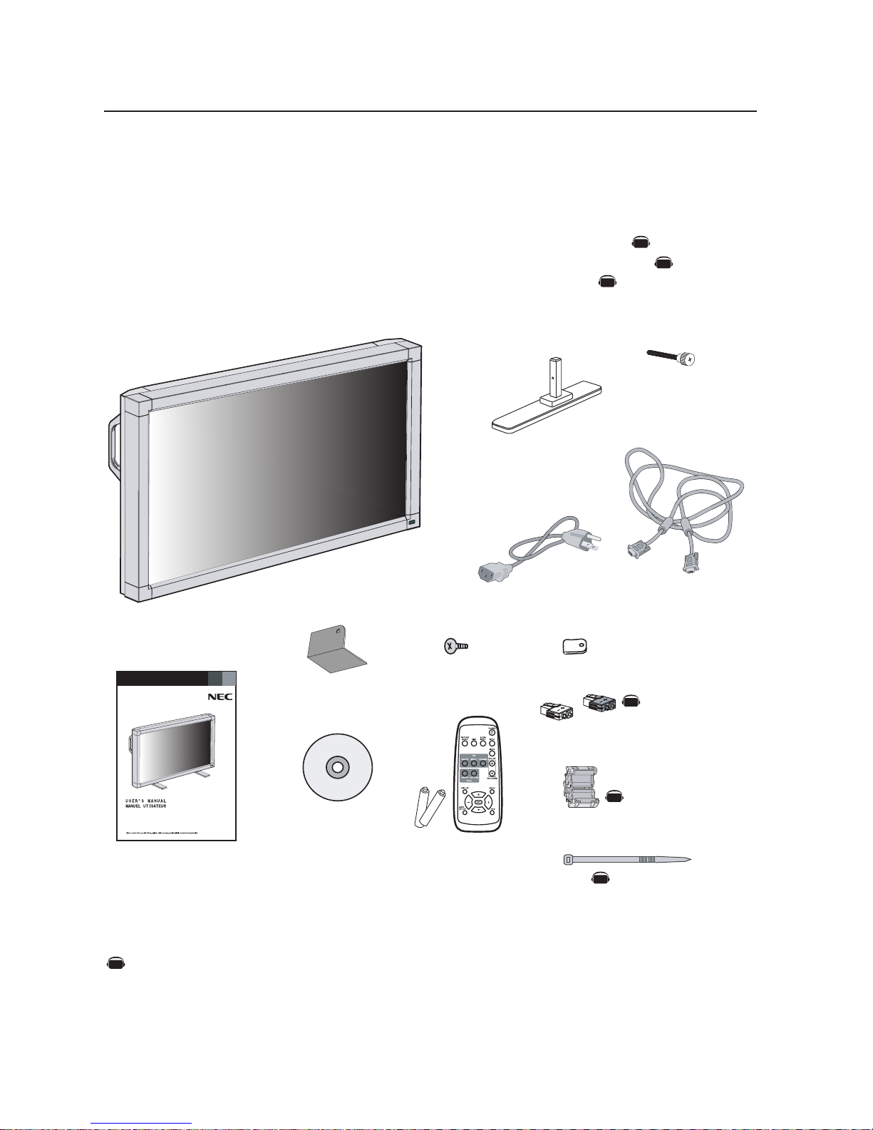
Contents
*Install at the time of unpacking if the display will be used with the stand.
*Remember to save your original box and packing material to transport or ship the monitor.
NOTE: The AV Unit is installed only on the LCD4010-BK(A)/LCD4610-BK(A).
Your new MultiSync® LCD4010™ / MultiSync® LCD4610™ monitor box* should contain the
following:
• LCD monitor
• Power Cord (3m)
• Video Signal Cable – SC-B113 (4m)
• User’s Manual
• Wireless Remote Control and AA Batteries
• Clamper x 3
• Screw (M4 x 8) x 4
Power Cord
User’s Manual
Video Signal Cable
(D-SUB to D-SUB Cable)
Wireless Remote Control
and AA Batteries
The following optional components are available to use with the MultiSync LCD4010 / MultiSync LCD4610. To obtain the
optional components and additional information, contact Customer Service at (800) 632-4662.
• Macintosh Cable Adapter
• External Speakers
Screw (M4 x 8 ) x 4
Band
x 2
CD-ROM
• CD-ROM
• Stand x 2
• Thumbscrew for stand x 2
• Main switch cover x 1
• Ferrite Core x 2
• Speaker Plug x 1 set
• Band x 2
Clamper x 3
Ferrite Core
x 2
Stand x 2
Thumbscrew
for stand x 2
Speaker Plug x 1 set
(Attached to external
speaker terminal)
Main switch cover x 1
AV
AV
AV
AV
AV
AV
Denotes an AV unit function.
All AV functions are enabled when the AV unit is installed.
AV
English-5
English
Screw Holes
Clamper
Cord or Chain
Screw
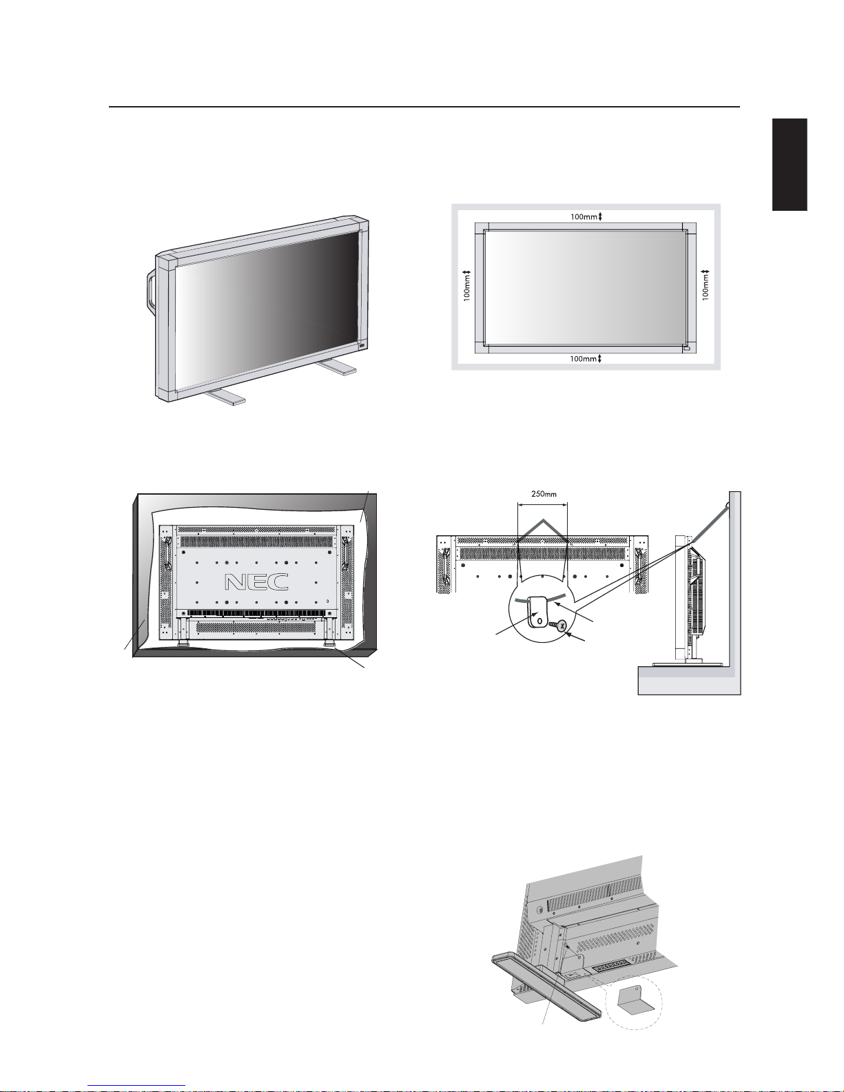
4. To prevent the LCD Monitor from
falling down
Fasten the LCD monitor to a wall using a cord or chain which is
sufficient to support the weight of the LCD monitor (approx. 27.5kg
for the LCD4010 and approx. 32.8kg for the LCD4610).
Before moving the LCD monitor, the cord or chain should be removed.
Attaching LCD Options
You can attach mounting accessories to the LCD monitor in one of
the following two ways:
1. In the upright position
2. Lay the screen face down
To avoid damaging the screen face, place the protective sheet on
the table underneath the LCD. The protective sheet was wrapped
around the LCD in the original packaging. Make sure there is nothing on the table that can damage the monitor.
This device cannot be used or installed without the Tabletop Stand
or other mounting accessory. For proper installation it is strongly
recommended to use a trained, NEC authorized service person.
Failure to follow NEC standard mounting procedures could result in
damage to the equipment or injury to the user or installer. Product
warranty does not cover damage caused by improper installation.
Failure to follow these recommendations could result in voiding your
warranty.
When using mounting accessories other than NEC compliant and
approved, they must comply with the VESA-compatible mounting
method. NEC strongly recommends using screws M6 size and
10mm in length. If using screws longer than 10mm, check the depth
of the hole. (Recommended Fasten Force: 470-635N•cm)
NEC recommends using mounting interface that comply with UL1678
standard in North America.
Tab le
Protective Sheet
Tab letop Stand
5. To prevent use of Main Power Switch
To prevent the use of the Main Power Switch, if desired, please attach the Main Power Switch cover which is included as an accessory.
NOTE: With the main power switch cover in place, the main power
switch can not be turned off. To turn the power off, remove the
main power switch cover and turn off the switch, or remove the
power cord from the AC Inlet at the back of the monitor.
3. Ventilation Requirements for enclosure
mounting
To allow heat to disperse, leave space between surrounding
objects as shown in the diagram below.
Main switch cover
Screw
English-6
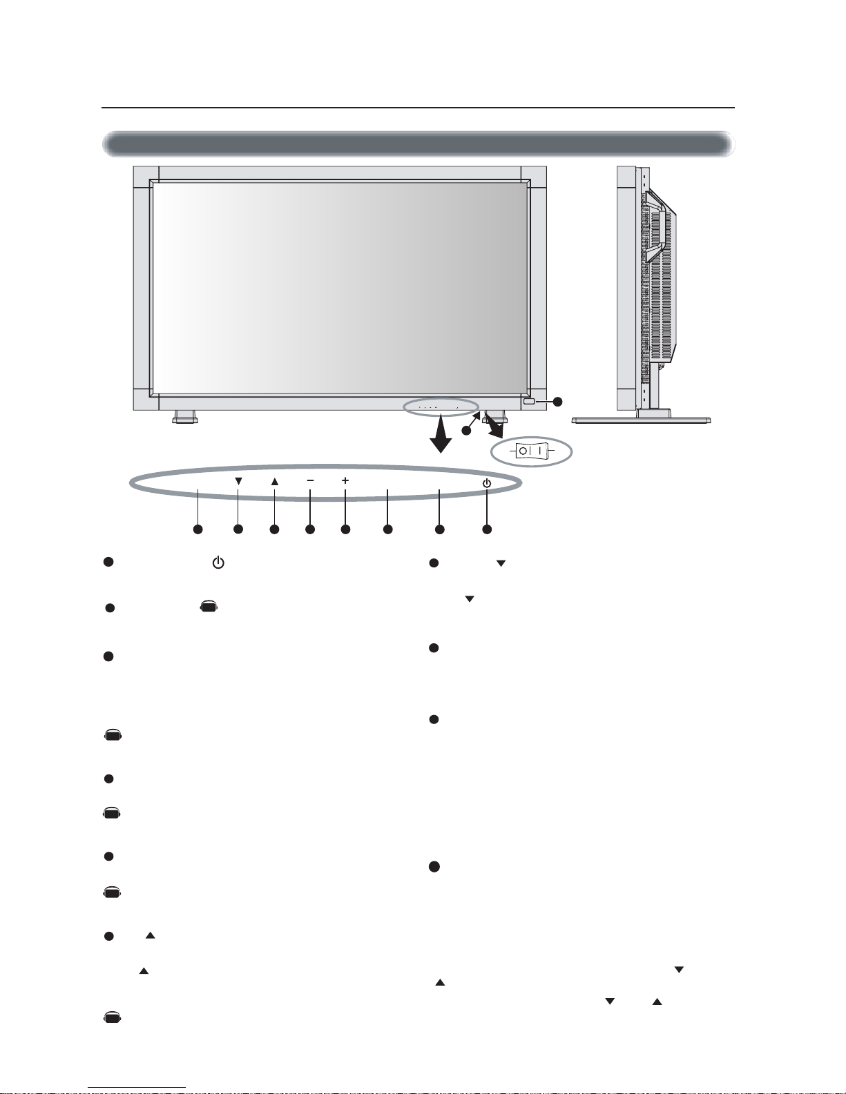
Control Panel
DOWN ( ) button
Activates the OSM menu when the OSM menu is turned-off.
Acts as button to move the highlighted area down to select the
adjustment with OSM menu.
EXIT button
Activates the OSM menu when the OSM menu is turned-off.
Acts as EXIT button to move to previous menu in the OSM menu.
Remote control sensor and Power indicator
Receives the signal from the remote control (when using the
wireless remote control). See page 9.
Glows green when the LCD monitor is in active mode and glows
red when the LCD is in POWER OFF mode. When the LCD is in
power save mode, it will glow both green and red. When
SCHEDULE is enabled, it will blink green. See page 19.
When a component failure is detected within the monitor, it will
blink red.
Main Power Switch
Seesaw Switch for the main power on/off.
Control Key Lock Mode
This control completely locks out access to all Control Key
functions.
To activate the control key lock function, press both “ “ and
“ “ simultaneously and hold down for three (3) seconds.
To go back to user mode, press both “ “ and “ “ simultaneously and hold for three (3) seconds.
POWER button ( )
Switches the power on/off. See page 18.
MUTE button
Switches the audio mute ON/OFF.
INPUT button
Acts as SET button within the OSM menu.
Selects which signal connected to the display is shown. (Toggle
switches between [RGB1], [RGB2], [RGB3], [DVD/HD], or
[VIDEO].)
[DVD/HD] and [VIDEO] inputs are enabled when the AV-unit
option is installed.
PLUS (+) button
Acts as (+) button to increase the adjustment with OSM menu.
Increases the audio output level when the OSM menu is turned
off.
MINUS (-) button
Acts as (-) button to decrease the adjustment with OSM menu.
Decreases the audio output level when the OSM menu is turned
off.
UP ( ) button
Activates the OSM menu when the OSM menu is turned-off.
Acts as button to move the highlighted area up to select the
adjustment with OSM menu.
Parts Name and Functions
Button Location
1
2
3
4
5
6
7
8
9
10
EXIT MUTEINPUT
8 1234
5
67
EXIT MUTEINPUT
9
10
ONOFF
AV
AV
AV
AV
Denotes an AV unit function.
All AV functions are enabled when the AV unit is installed.
AV

English
English-7
Terminal Panel
AUDIO IN 1,2,3
Input audio signal from external equipment such as a computer,
VCR or DVD player.
AUDIO OUT
Output the audio signal from the selected AUDIO IN source.
VIDEO INPUT/OUTPUT CONNECTOR
VIDEO IN connector (BNC and RCA): Input a composite video
signal. BNC and RCA are not available at the same time.
(Use only one input).
VIDEO OUT connector (BNC): Output the composite video
signal from the VIDEO IN source.
S-VIDEO IN connector (DIN 4 pin): Input the S-video (Y/C
separate signal). See page 26, S-VIDEO MODE SETTING.
EXTERNAL CONTROL (mini D-Sub 9 pin) RS-232C
In connector: Input signal from control equipment such as a
computer or the output from a different MultiSync LCD4010 /
MultiSync LCD4610.
Out connector: To connect multiple MultiSync LCD4010
/
MultiSync LCD4610
EXTERNAL SPEAKER TERMINAL
Outputs the audio signal from the selected audio source.
AC IN connector
Connects with the supplied power cord.
RGB 1 IN (DVI-D)
To input digital RGB signals from a computer or HDTV device
having a digital RGB output.
* This connector does not support analog input.
RGB 2 IN (mini D-Sub 15 pin)
To input analog RGB signals from a personal computer or other
RGB equipment.
RGB 3 [R, G, B, H, V] (BNC)
IN connector:
To input the analog RGB signals or signals from
other RGB equipment. A Sync-on-Green signal can be connected to the G connector.
RGB OUT connector (BNC)
To output the signal from the RGB 3 IN connector.
DVD/HD connector (BNC)
Connecting equipment such as a DVD player, HDTV device, or
Laser disc player.
Parts Name and Functions –continued
1
2
3
4
5
6
7
8
9
10
11
AV
AV
AV
AV
AV
Denotes an AV unit function.
All AV functions are enabled when the AV unit is installed.
AV

English-8
Wireless Remote Control
POWER button
Switches the power on/off.
* If Power Indicator is not glowing, then no controls will work.
INPUT button
Selects from input signal, [RGB1], [RGB2], [RGB3], [DVD/HD],
[VIDEO] and [VIDEO<S>].
[DVD/HD], [VIDEO] and [VIDEO<S>] inputs can be selected
when the AV optional module is installed.
[VIDEO<S>] is enabled by selecting the “SEPARATE” mode
in the OSM or by having the “S VIDEO” cable connected
with the “S VIDEO” signal present and selecting “PRIORITY”
MODE”. See page 26.
AUDIO INPUT button
Selects from input audio signal, [AUDIO1], [AUDIO2], [AUDIO3]
SIZE button
Selects picture size, [FULL], [NORMAL], [WIDE] and [ZOOM].
See page 19.
PICTURE MODE button
Selects from picture mode, [HIGHBRIGHT], [STANDARD],
[sRGB], [CINEMA]. See page 19.
HIGHBRIGHT: for moving image such as DVD
STANDARD: for images
sRGB: for text based images
CINEMA: for movies.
MUTE button
To turn on/off the mute function.
VOLUME UP button
Increase the audio output level.
VOLUME DOWN button
Decrease the audio output level.
PIP (Picture In Picture) button
ON/OFF button: Toggle switches between PIP,POP, side-by-side
(aspect) and side-by-side (full).
INPUT button: Select the ‘picture in picture’ input signal.
CHANGE button: Replaces to the main picture and sub
picture.
STILL button
ON/OFF button: To turn on/off the still picture mode.
CAPTURE button: Capture the new picture.
Note: Will not work when pixel clock is greater than 108MHz
DISPLAY button
To turn on/off the Information OSM. See page 19.
AUTO SETUP button
To enter the auto setup menu. See page 23.
MENU button
To turn on/off the menu mode.
UP button
Acts as button to move the highlighted area up to select the
adjustment with OSM menu.
Small screen which adjusted “PIP” mode moves up.
DOWN button
Acts as button to move the highlighted area down to select
the adjustment with OSM menu.
Small screen which adjusted “PIP” mode moves down.
MINUS button decrease
Acts as (-) button to decrease the adjustment with OSM menu.
Small screen which adjusted “PIP” mode moves left.
PLUS button increase
Acts as (+) button to increase the adjustment with OSM menu.
Small screen which adjusted “PIP” mode moves right.
SET button
Acts as SET button with OSM menu.
EXIT button
Turn to previous menu with OSM menu.
Parts Name and Functions –continued
2
3
4
5
6
7
8
9
10
11
12
13
14
15
16
17
18
19
1
RGB3 DVD/HD VIDEO
1BGR
___
2BGR
___
3BGR
___
DH/DVD
_
OEDIV
Sub Picture
Main Picture
Note: The aspect ratio of PIP synchronizes with a setup in the Main Picture.
RGB2RGB1
_
REMOTE
CONTROLLER RU-M104
AV
AV
AV
AV
AV
AV
AV
AV
AV
AV
AV
Denotes an AV unit function.
All AV functions are enabled when the AV unit is installed.
AV

English
English-9
Operating Range for the Remote Control
Point the top of the remote control toward the LCD monitor's remote
sensor while pressing button.
Use the remote control within a distance of about 7 m/23 ft. from
the front of the LCD monitor's remote control sensor and at a horizontal and vertical angle of within 30 degree within a distance of
about 3 m/10 ft.
*Do not open the remote control other than to install batteries.
*
Do not allow water or other liquid to splash onto the remote
control. If the remote control gets wet, wipe it dry immediately.
*Avoid exposure to heat and steam.
The remote control system may not function when direct sunlight or
strong illumination strikes the remote control sensor of the LCD monitor, or when there is an object in the path.
Parts Name and Functions –continued
Caution
Handling the remote control
REMOTE
CONTROLLER RU-M104
30 30

English-10
1. Determine the installation location
CAUTION
Installing your LCD display must be done by a qualified technician.
Contact your dealer for more information.
CAUTION
MOVING OR INSTALLING THE LCD MONITOR MUST BE DONE
BY TWO OR MORE PEOPLE. Failure to follow this caution may
result in injury if the LCD monitor falls.
CAUTION
Do not mount or operate the display upside down, face up, or face down.
CAUTION
This LCD has a temperature sensor and cooling fan. If the LCD becomes too hot, the cooling fan will turn on automatically. If the LCD
becomes overheated while the cooling fan is running, the “Caution”
menu will appear. If the “Caution” menu appears, discontinue use
and allow the unit to cool. Using the cooling fan will reduce the
likelihood of “Image Persistence”.
If the LCD is used in an enclosed area or if the LCD panel is covered
with a protective screen, please check the inside temperature of the
monitor by using the “HEAT STATUS” control in the OSM (see page
27). If the temperature is higher than the normal operating temperature, please turn the cooling fan to ON within the SCREEN SAVER
menu within the OSM (see page 24).
IMPORTANT
Lay the protective sheet, which was wrapped around the LCD monitor
when it was packaged, beneath the LCD monitor so as not to scratch
the panel.
2. Install the remote control batteries
The remote control is powered by 1.5V AA batteries. To install or
replace batteries:
1. Press and slide to open the cover.
2. Align the batteries according to the (+) and (–) indications inside the case.
3. Replace the cover.
CAUTION
Incorrect usage of batteries can result in leaks or bursting. NEC
recommends the following battery use:
• Place "AA" size batteries matching the + and - signs on each
battery to the + and - signs of the battery compartment.
• Do not mix battery brands.
• Do not combine new and old batteries. This can shorten battery
life or cause liquid leakage of batteries.
• Remove dead batteries immediately to prevent battery acid from
leaking into the battery compartment. Don't touch exposed battery acid, it can damage to your skin.
NOTE: If you do not intend to use the Remote Control for a
long period of time, remove the batteries.
3. Connect external equipment (See pages 12-17)
•To protect the external equipment, turn off the main power before making connections.
• Refer to your equipment user manual for further information.
Setup Procedure
4. Connect the supplied power cord
• The equipment should be installed close to an easily accessible
power outlet.
• Please attach power cord to the LCD monitor by attaching the
screw and clamper.
• Fully insert the prongs into the power outlet socket. Loose connection may cause image degradation.
NOTE: If you use this monitor at AC 220 - 240V, please refer
to “safety Precautions, Maintenance & recommended Use”
section of this manual for proper selection of AC power cord.
5. Switch on the power of all the attached
external equipment
When connected with a computer, switch on the power of the computer first.
6. Operate the attached external equipment
Display the signal from the desired input source.
7. Adjust the sound
Make volume adjustments as required.
8. Adjust the screen (See pages 20-28)
Make adjustments of the screen display position when necessary.
9. Adjust the image (See pages 20-28)
Make adjustments such as brightness or contrast when required.
AV
Screwhole for clamper
Denotes an AV unit function.
All AV functions are enabled when the AV unit is installed.
AV

English
English-11
10. Recommended Adjustments
To reduce the risk of the “image persistence”, please adjust the following items based on the application being used.
“SCREEN SAVER” (See page 24), see page ”SIDE BORDER COLOR”
(See page 24), “DATE & TIME” (See page 27), “SCHEDULE” (See
page 27)
11. When the monitor is installed in the portrait position
• Remove the stands (feet).
• Left edge should be the upper edge from front view.
12. Installing and removing stand
How to install stand
1. Please turn monitor off.
2. Place stand onto monitor with the long ends of the feet in front
of the monitor.
3. After inserting stand in guide block, fasten thumbscrews on both
sides of the monitor.
How to remove the stand
1. Spread the protective sheet on a flat surface, such as a desk.
2. Place monitor on the protective sheet.
3. Remove thumbscrews with a screwdriver or with your fingers
and place them in a safe place for reuse.
13. When using external speakers
We recommend using the optional speakers designed for the
MultiSync LCD4010 / MultiSync LCD4610.
The external speaker terminals of the MultiSync LCD4010 / MultiSync
LCD4610 may be connected with the speaker plug of a mainframe
sound speaker. It this case, please exchange the lead connector of a
mainframe sound speaker for an attached speaker plug.
Setup Procedure –continued
Stand
Thumbscrews
Speaker plug
Insert the negative (-) side of a standard speaker
cable into the negative (-) side of the speaker
plug. The negative side of a standard speaker
cable has a stripe running the length of the cable.
Insert remaining wire into the positive (+) side
of the speaker plug. Hold down on the small
lever on the speaker plug to insert cable.
Fixed cable and speaker plug.
Insert the fixed cable and speaker plug to the speaker terminal.
Speaker terminal
Standard cable
AV
NOTE: Place stand onto monitor
so that the long end of the feet
are in the front
Denotes an AV unit function.
All AV functions are enabled when the AV unit is installed.
AV
•How to use the attached speaker plug
AV

English-12
Attaching the Ferrite Core Mounting Position of Ferrite Core
Open the ferrite core and clamp
it on the PC Audio cable.
Close the ferrite core.
Ferrite Core
To AUDIO 1 of monitor
To connector of PC
1
2
Attach the Ferrite Core to PC Audio Cable.
Use of the cable without mounting the ferrite core may result in the
occurrence of noise.
Attach the Ferrite Core to the both ends of PC Audio Cable.
• For PC Audio Cable
Ferrite Core
Band Band
Ferrite Core
AV
Before connecting external equipment to LCD:
* First turn off the power to all of the equipment associated with the LCD as well as that of the equipment to be connected.
* For questions regarding external equipment please refer to the user’s manual supplied with that equipment.
Wiring Diagram
AV
AV
AV
AV
AV
Denotes an AV unit function.
All AV functions are enabled when the AV unit is installed.
AV
Connections

English
English-13
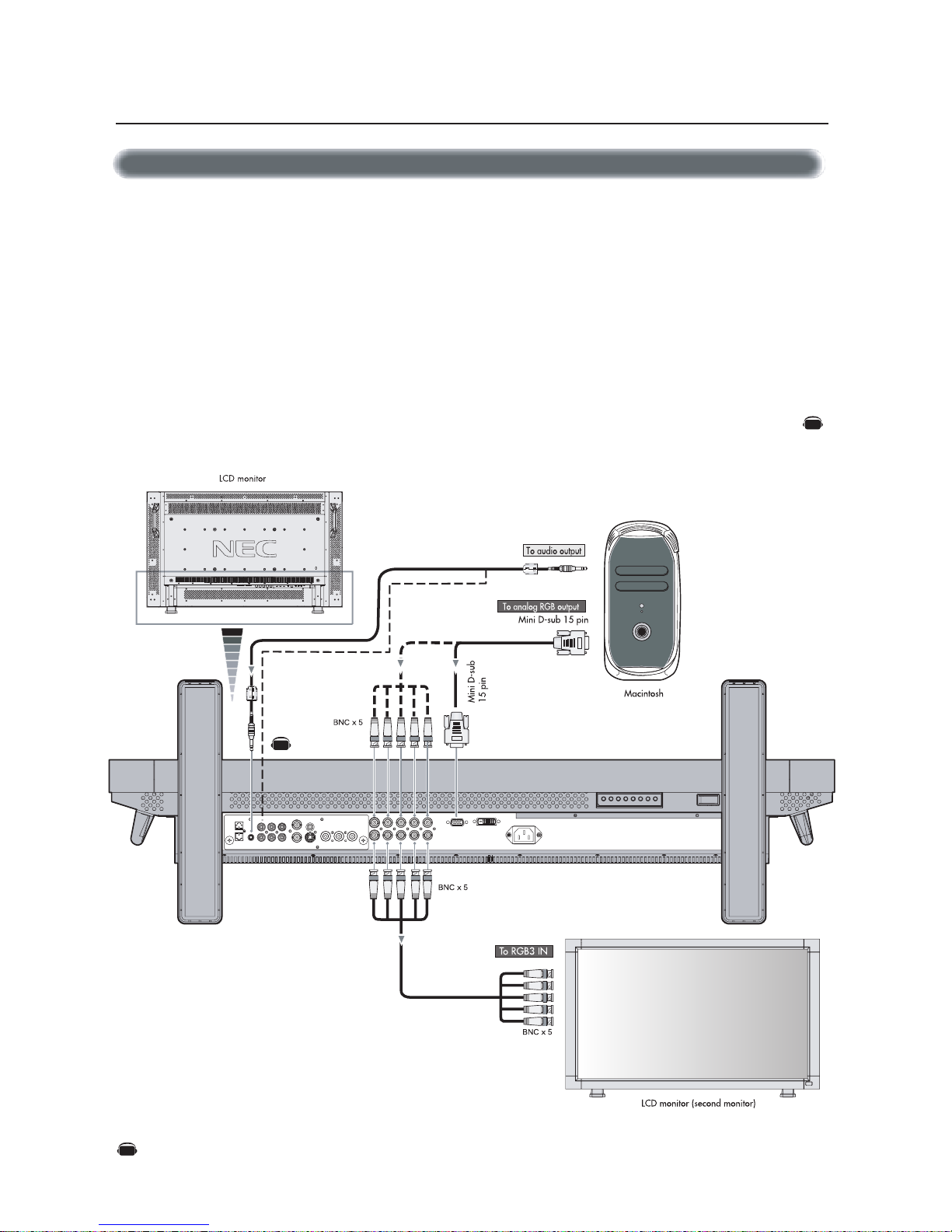
Connecting your computer to your LCD monitor will enable you to display your computer's screen image.
Some video cards may not display an image correctly.
•To connect the RGB 2 IN connector (mini D-sub 15 pin) on the LCD monitor, use the provided RGB signal cable (mini D-sub 15 pin to
mini D-sub 15 pin).
•To connect the RGB 3 connector (BNC) on the LCD monitor, use a signal cable (mini D-sub 15 pin to BNC x 5). Select RGB 3 from the
INPUT button.
When connecting one or more LCD monitor, use the RGB OUT connector (BNC).
• The AUDIO IN 1, 2 and 3 can be used for audio input. For connection, select AUDIO 1, 2 or 3 from the AUDIO INPUT button.
Connecting the LCD Monitor to a PC
Connections –continued
AV
AV
Denotes an AV unit function.
All AV functions are enabled when the AV unit is installed.
AV
English-14
Connecting your Macintosh® computer to your LCD monitor will enable you to display your computer's screen image. Some video cards or
drivers may not display images correctly.
•To connect the RGB 2 IN connector (mini D-sub 15 pin) on the LCD monitor, use the provided RGB signal cable (mini D-sub 15 pin to
mini D-sub 15 pin).
For older Macintosh
®
computers, use Macintosh cable adapter to connect to your Macintosh's video port.
NOTE: To obtain the Macintosh cable adapter call NEC-Mitsubishi Electronics Display of America, Inc. at (800) 632-4662
•To connect the RGB 3 IN connector (BNC) on the LCD monitor, use the signal cable available separately (mini D-sub 15 pin to
BNC x 5).
• If you will be connecting the LCD monitor to a Macintosh PowerBook, set "Mirroring" to off.
Refer to your Macintosh's owner's manual for more information about your computer's video output requirements and any special
identification or configuring that may be required.
• The AUDIO IN 1, 2 and 3 can be used for audio input. For connection, select AUDIO 1, 2 or 3 from the AUDIO INPUT button.
Connecting to a Macintosh® Computer
Connections –continued
AV
AV
Denotes an AV unit function.
All AV functions are enabled when the AV unit is installed.
AV
English
English-15
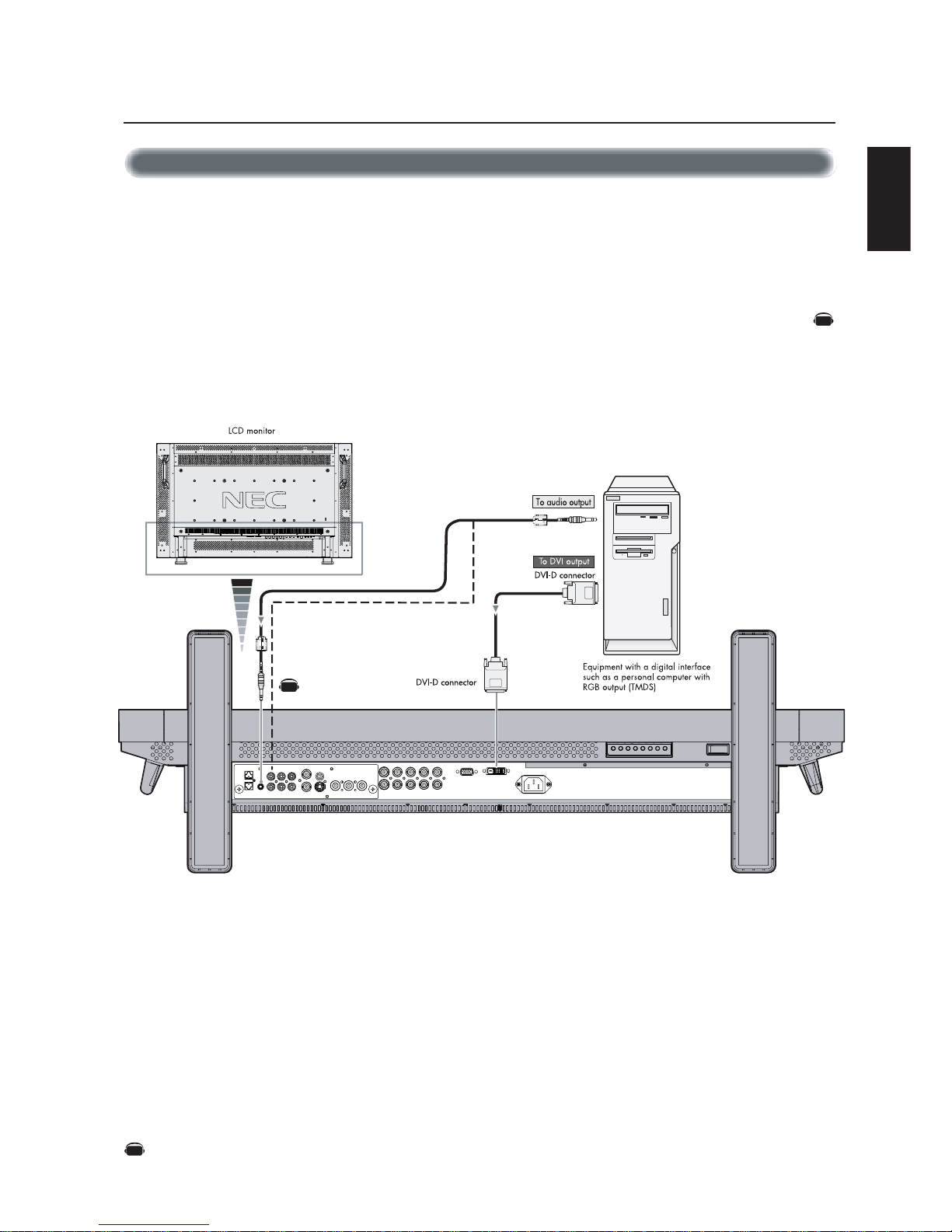
Connections can be made with equipment that is equipped with a digital interface compliant with the DVI (Digital Visual Interface)
standard.
Connecting to a Computer with a Digital Output
Connections –continued
AV
AV
• The RGB 1 IN connector also accepts a DVI-D cable.
• Input TMDS signals conforming to DVI standards.
•To maintain display quality, use a cable recommended by DVI standards.
• The AUDIO IN 1, 2 and 3 can be used for audio input. For connection, select AUDIO 1, 2 or 3 from the AUDIO INPUT button.
• Mode selection see “DVI MODE” of page 25.
Denotes an AV unit function.
All AV functions are enabled when the AV unit is installed.
AV
English-16
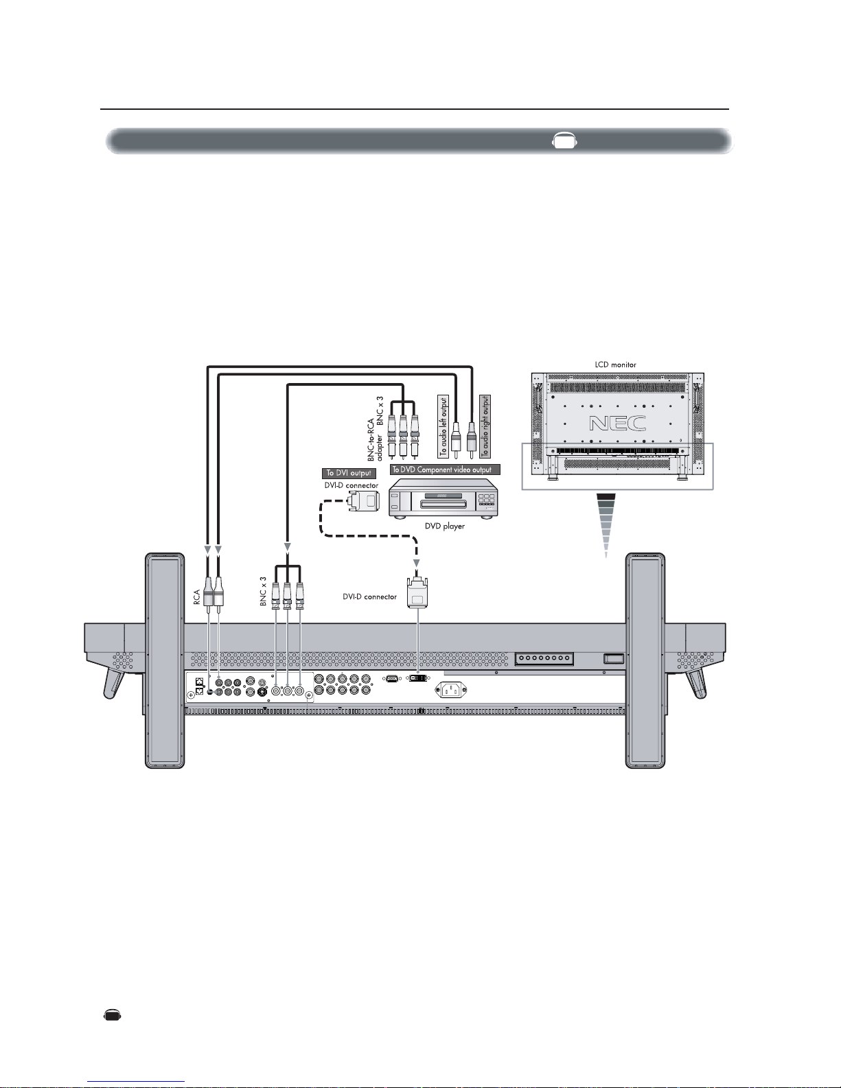
Connecting your DVD player to your LCD monitor will enable you to display your DVD video.
Refer to your DVD player’s owner’s manual for additional information.
Connecting to a DVD Player
Connections –continued
•To connect the DVD/HD IN connector (BNC) on the LCD monitor, use a separately available BNC connector cable. You will need a
BNC-to-RCA adapter to connect a DVD player with an RCA pin jack to the BNC connector cable (not provided).
Some DVD players may have different connectors, such as DVD/HD connector (Y, Cb/Pb and Cr/Pr).
Select [DVD/HD] input mode from the INPUT button.
The AUDIO IN 2 and 3 (both RCA) can be used for audio input. For connection, select [AUDIO 2] or [AUDIO 3] from the AUDIO
INPUT button.
• Mode selection see “DVI MODE” of page 25.
AV
Denotes an AV unit function.
All AV functions are enabled when the AV unit is installed.
AV
English
English-17
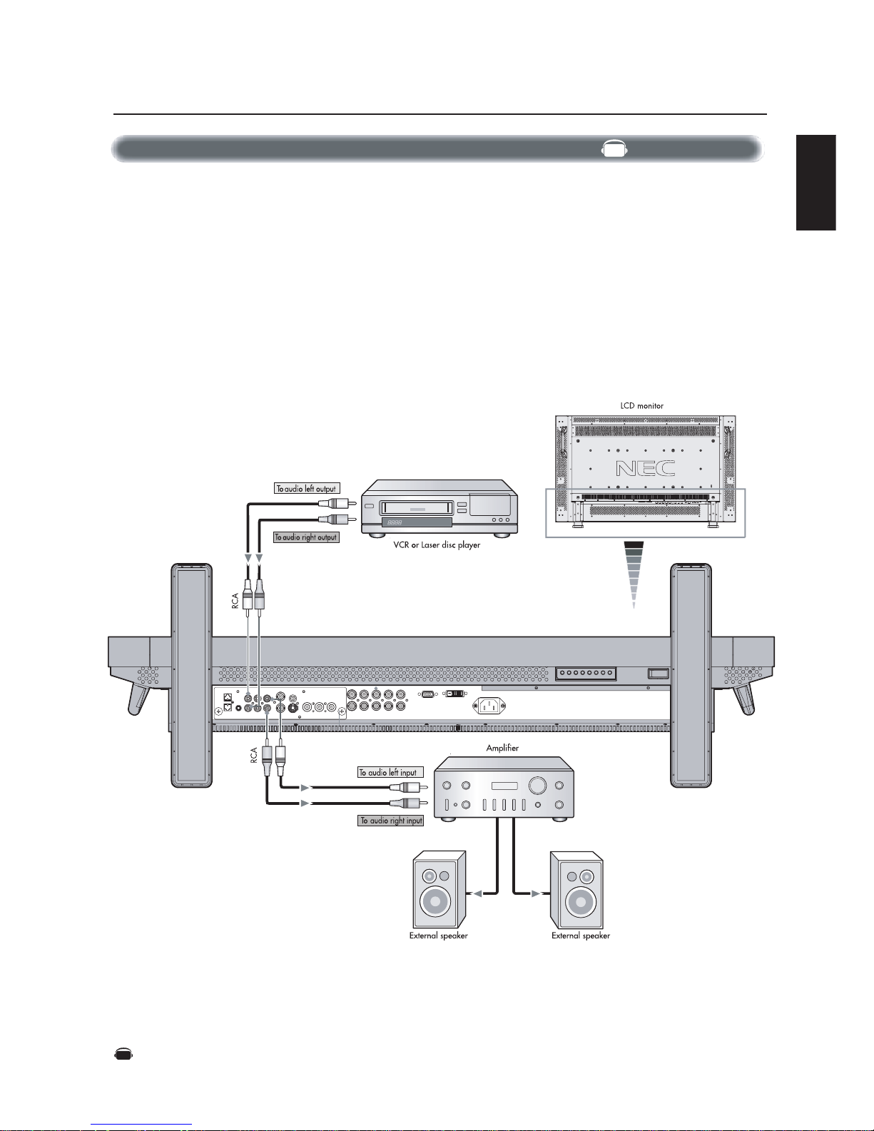
You can connect your stereo amplifier to your LCD monitor. Refer to your amplifier's owner's manual for additional information.
Connecting to a Stereo Amplifier
•Turn on the LCD monitor and the amplifier only after all connections have been made.
• Use an RCA cable to connect the AUDIO OUT connector (RCA) on the LCD monitor and the audio input on the amplifier.
• Do not reverse the audio left and right jacks.
• The AUDIO IN used for audio input.
• The AUDIO OUT jack outputs sound from the Audio input device (VCR) selected by the LCD monitor to the
external output device (stereo amplifier).
Connections –continued
AV
Denotes an AV unit function.
All AV functions are enabled when the AV unit is installed.
AV

English-18
Basic Operation –Power ON and OFF Modes
1. Pressing the power button.
NOTE: Before pressing the power button, be sure to turn on
the Main Power Switch on the LCD monitor.
2. Using the remote control
NOTE: Before operating the remote control, be sure to turn
on the Main Power Switch on the LCD monitor.
3. Pressing the Main Power Switch.
NOTE: When the Main Power Switch is used to power off
the LCD, the remote control and the power button will not
activate the LCD. Be sure to turn the Main Power Switch to
“ON” before using options 1 or 2.
The LCD monitor power indicator will turn green while powered on and will turn red while powered off. The monitor can be powered on
or off using the following three options:
Power Button
Main Power Switch
REMOTE
CONTROLLER RU-M104
English
English-19
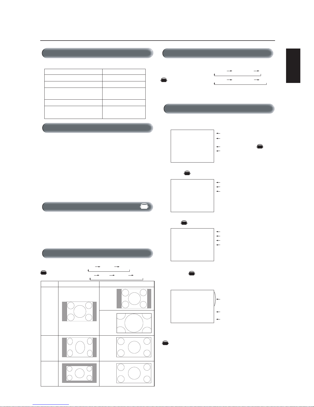
Signal Type
4:3
NORMAL SIZE RECOMMENDED SIZE
NORMAL
ZOOM
(DYNAMIC)
FULL
WIDE
Squeeze
Letterbox
RGB 1, 2, 3
DVD/HD, VIDEO
FULL ZOOM NORMAL
FULL WIDE ZOOM NORMAL
Picture Mode
RGB 1, 2, 3
DVD/HD, VIDEO
HIGHBRIGHT STANDARD sRGB
HIGHBRIGHT STANDARD CINEM
A
The LCD monitor follows the VESA approved DPM Power Management function.
The power management function is an energy saving function that
automatically reduces the power consumption of the display when
the keyboard or the mouse has not been used for a fixed period of
time.
The power management feature on your new display has been set to
the “ON” mode. This allows your display to enter a Power Saving
Mode when no signal is detected. This could potentially increase the
life and decrease the power consumption of the display.
To view a video source:
Use the input button to set [VIDEO].
Use the COLOR SYSTEM menu to set, [AUTO], [NTSC], [PAL],
[SECAM], [PAL60], [4.43NTSC] in according to your video format.
Basic Operation –continued
Power Indicator
Status
Power ON Green
Power OFF Red
Power Standby Red On
when “SCHEDULE” is enabled Green Blinking
Power Standby Red , Green
Information OSM
RGB1, 2, 3
DVD/HD
V
IDEO
PIP or POP
Main:RGB2
Sub:VIDEO<S>
Video Input mode
Input signal Information
Audio input mode
Picture Size mode
Video Input mode
Audio input mode
Picture Size mode
Main picture Information
Sub picture Information
Main picture Information
Video Input mode
Input Signal Color System mod
e
Audio input mode
Picture Size mode
RGB2
1024 x 768
48kHz 60Hz
AUDIO : 1
SIZE : FULL
DVD/HD
AUDIO : 3
SIZE : WIDE
VIDEO<S>
NTSC
AUDIO : 3
SIZE : NORMAL
RGB2
1024 x 768
48kHz 60Hz
AUDIO : 1
VIDEO<S>
NTSC
SIZE : FULL
)
)
Power Indicator
AV
AV
AV
AV
AV
Diagnosis (Detecting failure) Red Blinking
*See trouble shooting of page 33
When Using Power Management Function
Selecting a Video Source
Picture Size
AV
AV
Denotes an AV unit function.
All AV functions are enabled when the AV unit is installed.
AV
English-20
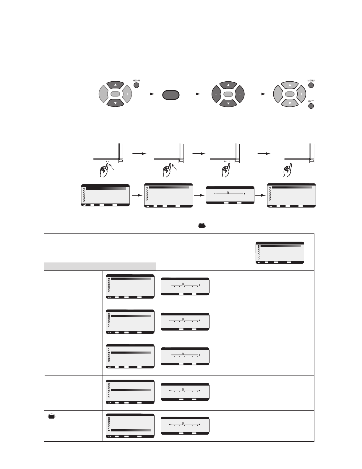
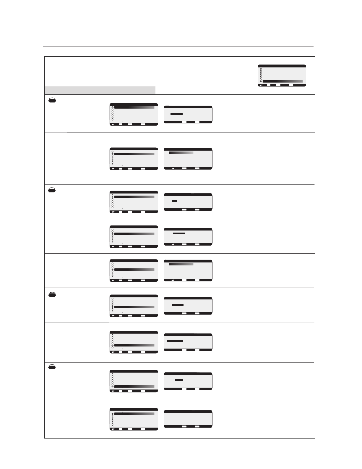
OSM (On-Screen Manager) Controls-Picture
PICTURE
SET
SET
Press MENU button to open
Main-menu
Press UP or DOWN button
to select sub-menu
Press UP or DOWN button to
select
UP or DOWN button INPUT button
Press the UP, DOWN, PLUS, or
MINUS buttons to select options
and to make adjustments to
settings
Press INPUT button to select
Press INPUT button to
decide
Press EXIT button to
exit
SET
Press the UP, DOWN, PLUS, or
MINUS buttons to select options
and to make adjustments to
settings
Press SET button to select
Press SET button to
decide
Sub-Menu
Main-Menu
Remote Control
Control Panel
OSM screen
Adjusts the overall image and background screen
brightness.
Press + button to increase brightness.
Press - button to decrease brightness.
Adjusts the image brightness in relation to the input
signal.
Press + button to increase contrast.
Press - button to decrease contrast.
NOTE: sRGB picture mode is standard and cannot be
changed.
Adjusts the crispness of what is displayed on the
screen. Can be set to get a distinct (sharp) image or a
soft image as is preferred. Set independently for each
Picture Mode.
Press + button to increase sharpness.
Press - button to decrease sharpness.
Adjusts the image brightness in relation to the
background.
Press + button to increase black level.
Press - button to decrease black level.
NOTE: sRGB picture mode is standard and cannot be
changed.
INPUT
EXIT
BRIGHTNESS
CONTRAST
SHARPNESS
BLACK LEVEL
NOISE REDUCTION
*:INPUT VIDEO only
Press MENU or EXIT
button to exit
SET
Adjusts the noise reduction level.
Press + button to increase reduction level.
Press - button to decrease reduction level.
MAIN MENU
PICTURE
SCREEN
AUDIO
PIP
CONFIGURATION 1
CONFIGURATION 2
ADVANCED OPTION
:SEL
SET
:NEXT
EXIT
:RETURN
MENU
:EXIT MENU
MAIN MENU
PICTURE
SCREEN
AUDIO
PIP
CONFIGURATION 1
CONFIGURATION 2
ADVANCED OPTION
:SEL
SET
:NEXT
EXIT
:RETURN
MENU
:EXIT MENU
PICTURE
BRIGHTNESS
CONTRAST
SHARPNESS
BLACK LEVEL
COLOR CONTROL
COLOR TEMPERATURE
PICTURE RESET
:SEL
SET
:NEXT
EXIT
:RETURN
MENU
:EXIT MENU
PICTURE
BRIGHTNESS
CONTRAST
SHARPNESS
BLACK LEVEL
COLOR CONTROL
COLOR TEMPERATURE
PICTURE RESET
:SEL
SET
:NEXT
EXIT
:RETURN
MENU
:EXIT MENU
PICTURE
BRIGHTNESS
CONTRAST
SHARPNESS
BLACK LEVEL
COLOR CONTROL
COLOR TEMPERATURE
PICTURE RESET
:SEL
SET
:NEXT
EXIT
:RETURN
MENU
:EXIT MENU
+ -:ADJ
EXIT
:RETURN
MENU
:EXIT MENU
32
BRIGHTNESS
+ -:ADJ
EXIT
:RETURN
MENU
:EXIT MENU
32
BRIGHTNESS
CONTRAST
+ -:ADJ
EXIT
:RETURN
MENU
:EXIT MENU
32
PICTURE
BRIGHTNESS
CONTRAST
SHARPNESS
BLACK LEVEL
COLOR CONTROL
COLOR TEMPERATURE
PICTURE RESET
:SEL
SET
:NEXT
EXIT
:RETURN
MENU
:EXIT MENU
PICTURE
BRIGHTNESS
CONTRAST
SHARPNESS
BLACK LEVEL
COLOR CONTROL
COLOR TEMPERATURE
PICTURE RESET
:SEL
SET
:NEXT
EXIT
:RETURN
MENU
:EXIT MENU
+ -:ADJ
EXIT
:RETURN
MENU
:EXIT MENU
32
SHARPNESS
PICTURE
BRIGHTNESS
CONTRAST
SHARPNESS
BLACK LEVEL
COLOR CONTROL
COLOR TEMPERATURE
PICTURE RESET
:SEL
SET
:NEXT
EXIT
:RETURN
MENU
:EXIT MENU
+ -:ADJ
EXIT
:RETURN
MENU
:EXIT MENU
32
BLACK LEVEL
PICTURE
BRIGHTNESS
CONTRAST
SHARPNESS
TINT
COLOR
BLACK LEVEL
NOISE REDUCTION
:SEL
SET
:NEXT
EXIT
:RETURN
MENU
:EXIT MENU
+ -:ADJ
EXIT
:RETURN
MENU
:EXIT MENU
32
NOISE REDUCTION
NOTE: Items in this OSM menu may change depending on connection type and with the AV unit installed.
AV
Denotes an AV unit function.
All AV functions are enabled when the AV unit is installed.
AV

English
English-21
OSM Controls-Screen
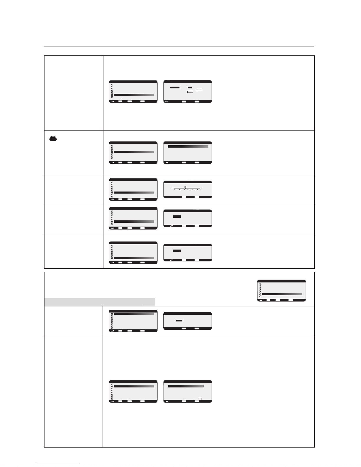
Adjusts the color temperature of entire screen.
Choosing a lower color temperature will make the
screen reddish and a higher color temperature make
the screen bluish.
NOTE: sRGB picture mode is standard and cannot be
changed.
Selecting Picture Reset allows you to reset all OSM
settings within the PICTURE menu.
Select "YES" and press "SET" button to restore the
factory settings.
Press "EXIT" button to cancel and Press "EXIT" again to
return the previous menu.
TINT
COLOR
COLOR CONTROL
COLOR
TEMPERATURE
PICTURE RESET
R, Y, G, C, B, M, S: Increases or decreases Red, Yellow,
Green, Cyan, Blue, Magenta and Saturation depending upon
which is selected. The change in color will appear on screen
and the direction (increase or decrease) will be shown by the
color bars.
NOTE: sRGB picture mode is standard and cannot be
changed.
*:INPUT DVD/HD,VIDEO
only
*:INPUT DVD/HD,VIDEO
only
Adjusts the tint of the screen.
Press + button the flesh tone color becomes greenish.
Press - button
the flesh tone
color becomes purplish.
Adjusts the color depth of the screen.
Press + button to increase color depth.
Press - button to decrease color depth.
H POSITION
V POSITION
CLOCK
CLOCK PHASE
H RESOLUTION
Sub-Menu
Main-Menu
Controls Horizontal Image position within the display
area of the LCD.
Press + button to move screen to right.
Press - button to move screen to left.
Controls Vertical Image position within the display
area of the LCD.
Press + button to move screen to UP.
Press - button to move screen to DOWN.
Press + button to expand the width of the image on the
screen to the right.
Press - button to narrow the width of the image on the
screen to the left.
Adjusts the visual snow noise on the image.
Adjusts the horizontal size by increasing or decreasing
the setting.
Press + button to expand the width of the image on the
screen.
Press - button to narrow the width of the image on the
screen.
SCREEN
*:INPUT RGB2/3 only
*:INPUT RGB2/3 only
*:INPUT RGB1/2/3 only
PICTURE
BRIGHTNESS
CONTRAST
SHARPNESS
TINT
COLOR
BLACK LEVEL
NOISE REDUCTION
:SEL
SET
:NEXT
EXIT
:RETURN
MENU
:EXIT MENU
+ -:ADJ
EXIT
:RETURN
MENU
:EXIT MENU
32
TINT
PICTURE
BRIGHTNESS
CONTRAST
SHARPNESS
TINT
COLOR
BLACK LEVEL
NOISE REDUCTION
:SEL
SET
:NEXT
EXIT
:RETURN
MENU
:EXIT MENU
+ -:ADJ
EXIT
:RETURN
MENU
:EXIT MENU
32
COLOR
PICTURE
BRIGHTNESS
CONTRAST
SHARPNESS
BLACK LEVEL
COLOR CONTROL
COLOR TEMPERATURE
PICTURE RESET
:SEL
SET
:NEXT
EXIT
:RETURN
MENU
:EXIT MENU
PICTURE
BRIGHTNESS
CONTRAST
SHARPNESS
BLACK LEVEL
COLOR CONTROL
COLOR TEMPERATURE
PICTURE RESET
:SEL
SET
:NEXT
EXIT
:RETURN
MENU
:EXIT MENU
+ -:ADJ
EXIT
:RETURN
MENU
:EXIT MENU
9600K
COLOR TEMPERATURE
PICTURE
BRIGHTNESS
CONTRAST
SHARPNESS
BLACK LEVEL
COLOR CONTROL
COLOR TEMPERATURE
PICTURE RESET
:SEL
SET
:NEXT
EXIT
:RETURN
MENU
:EXIT MENU
SCREEN
H POSITION
V POSITION
CLOCK
CLOCK PHASE
H RESOLUTION
V RESOLUTION
ZOOM MODE
SCREEN RESET
:SEL
SET
:NEXT
EXIT
:RETURN
MENU
:EXIT MENU
MAIN MENU
PICTURE
SCREEN
AUDIO
PIP
CONFIGURATION 1
CONFIGURATION 2
ADVANCED OPTION
:SEL
SET
:NEXT
EXIT
:RETURN
MENU
:EXIT MENU
+ -:ADJ
EXIT
:RETURN
MENU
:EXIT MENU
0
H POSITION
SCREEN
H POSITION
V POSITION
CLOCK
CLOCK PHASE
H RESOLUTION
V RESOLUTION
ZOOM MODE
SCREEN RESET
:SEL
SET
:NEXT
EXIT
:RETURN
MENU
:EXIT MENU
+ -:ADJ
EXIT
:RETURN
MENU
:EXIT MENU
0
V POSITION
SCREEN
H POSITION
V POSITION
CLOCK
CLOCK PHASE
H RESOLUTION
V RESOLUTION
ZOOM MODE
SCREEN RESET
:SEL
SET
:NEXT
EXIT
:RETURN
MENU
:EXIT MENU
+ -:ADJ
EXIT
:RETURN
MENU
:EXIT MENU
1782
CLOCK
SCREEN
H POSITION
V POSITION
CLOCK
CLOCK PHASE
H RESOLUTION
V RESOLUTION
ZOOM MODE
SCREEN RESET
:SEL
SET
:NEXT
EXIT
:RETURN
MENU
:EXIT MENU
+ -:ADJ
EXIT
:RETURN
MENU
:EXIT MENU
18
CLOCK PHASE
SCREEN
H POSITION
V POSITION
CLOCK
CLOCK PHASE
H RESOLUTION
V RESOLUTION
ZOOM MODE
SCREEN RESET
:SEL
SET
:NEXT
EXIT
:RETURN
MENU
:EXIT MENU
+ -:ADJ
EXIT
:RETURN
MENU
:EXIT MENU
1360
H RESOLUTION
*:INPUT RGB1,2,3 only
+ -:ADJ
EXIT
:RETURN
MENU
:EXIT MENU
COLOR CONTROL
R
Y
G
C
B
M
S
0
0
0
0
0
0
0
:SEL
PICTURE RESET
EXIT
:RETURN
MENU
:EXIT MENU
NO
YES
:SEL
AV
AV

English-22
V RESOLUTION
ZOOM MODE
SCREEN RESET
Adjusts the vertical size by increasing or decreasing
the setting.
Press + button to expand the height of the image on
the screen.
Press - button to narrow the height of the image on the
screen.
Selecting Screen reset allows you to reset all OSM
settings within SCREEN menu.
Select "YES" and press "SET" button to restore the
factory preset data.
Press "EXIT" button to cancel. Press "EXIT" again to
return the previous menu.
*:INPUT RGB1/2/3 only
*:INPUT DVD/HD, VIDEO only
Selects the screen zoom mode. "ZOOM" mode can
be selected pressing the "SIZE" button on the remote
control.
When you select the "CUSTOM" setting, you will be
able to set custom horizontal and vertical size.
When you select the "16:9" setting, the screen will
stretch 4:3 to 16:9 and then you will be able to
adjust optional horizontal and vertical size.
(INPUT DVD/HD, VIDEO only)
Press "SET" button to show the control menu as
follows,
Increase or decrease "ZOOM" slider to adjust the
whole size. Adjust horizontal size with H ZOOM and
vertical size with V ZOOM. Increase or decrease "H
POS" and "V POS" to adjust the picture position.
Selecting "OFF" will display the image in a 1 by
1pixel format. (If the input resolution is higher than a
1366 x 768 resolution, the image will be scaled
down to fit the screen.)
Selecting Audio reset allows you to reset all OSM
settings fwithin Audio menu.
Select "YES" and press "SET" button to restore the
factory preset.
Press "EXIT" button to cancel. Press "EXIT" again to
return the previous menu.
BALANCE
TREBLE
BASS
AUDIO RESET
Sub-Menu
Main-Menu
Adjusts the high frequency sound.
Press + button to increase TREBLE sound.
Press - button to decrease TREBLE sound.
Asjusts the low frequency sound.
Press + button to increase BASS sound.
Press - button to decrease BASS sound.
AUDIO
Adjusts the balance of stereo sound.
Press + button to move the stereo sound image to right.
Sound of the left side will be quieter.
Press - button to move the stereo sound image to left.
Sound of the right side will be quieter.
SCREEN
H POSITION
V POSITION
CLOCK
CLOCK PHASE
H RESOLUTION
V RESOLUTION
ZOOM MODE
SCREEN RESET
:SEL
SET
:NEXT
EXIT
:RETURN
MENU
:EXIT MENU
+ -:ADJ
EXIT
:RETURN
MENU
:EXIT MENU
768
V RESOLUTION
SCREEN
H POSITION
V POSITION
CLOCK
CLOCK PHASE
H RESOLUTION
V RESOLUTION
ZOOM MODE
SCREEN RESET
:SEL
SET
:NEXT
EXIT
:RETURN
MENU
:EXIT MENU
ZOOM MODE
CUSTOM
OFF
:SEL
SET
:NEXT
EXIT
:RETURN
MENU
:EXIT MENU
ZOOM MODE
CUSTOM
16:9
14:9
DYNAMIC
OFF
:SEL
SET
:NEXT
EXIT
:RETURN
MENU
:EXIT MENU
CUSTOM
:SEL + - :ADJ
EXIT
:RETURN
MENU
:EXIT MENU
X 1.00
X 1.00
X 1.00
0%
0%
ZOOM
H ZOOM
V ZOOM
H POS
V POS
SCREEN
H POSITION
V POSITION
CLOCK
CLOCK PHASE
H RESOLUTION
V RESOLUTION
ZOOM MODE
SCREEN RESET
:SEL
SET
:NEXT
EXIT
:RETURN
MENU
:EXIT MENU
AUDIO
BALANCE
TREBLE
BASS
AUDIO RESET
:SEL
SET
:NEXT
EXIT
:RETURN
MENU
:EXIT MENU
MAIN MENU
PICTURE
SCREEN
AUDIO
PIP
CONFIGURATION 1
CONFIGURATION 2
ADVANCED OPTION
:SEL
SET
:NEXT
EXIT
:RETURN
MENU
:EXIT MENU
AUDIO
BALANCE
TREBLE
BASS
AUDIO RESET
:SEL
SET
:NEXT
EXIT
:RETURN
MENU
:EXIT MENU
+ -:ADJ
EXIT
:RETURN
MENU
:EXIT MENU
R CENTER
BALANCE
L
AUDIO
BALANCE
TREBLE
BASS
AUDIO RESET
:SEL
SET
:NEXT
EXIT
:RETURN
MENU
:EXIT MENU
+ -:ADJ
EXIT
:RETURN
MENU
:EXIT MENU
0
TREBLE
AUDIO
BALANCE
TREBLE
BASS
AUDIO RESET
:SEL
SET
:NEXT
EXIT
:RETURN
MENU
:EXIT MENU
+ -:ADJ
EXIT
:RETURN
MENU
:EXIT MENU
0
BASS
SCREEN RESET
EXIT
:RETURN
MENU
:EXIT MENU
NO
YES
:SEL
AUDIO RESET
EXIT
:RETURN
MENU
:EXIT MENU
NO
YES
:SEL
Selecting "DYNAMIC" will expand 4:3 picture to fill the
screen with non-linearity. (Some of the image is lost due
to expansion.) Dynamic image is the same as FULL size
image when HDTV 1080i or 720p signal is input
*:INPUT RGB1/2/3 only
OSM Controls-Audio
AV
AV
AV
AV
AV
AV
AV

English
English-23
PIP
PIP SIZE
PIP AUDIO
PIP RESET
:SEL
SET
:NEXT
EXIT
:RETURN
MENU
:EXIT MENU
AUTO SETUP
AUTO ADJUST
AUTO BRIGHTNESS
POWER SAVE
LANGUAGE
*:INPUT RGB2/3 only
*:INPUT RGB2/3 only
*:INPUT RGB1/2/3 only
PIP SIZE
PIP AUDIO
PIP RESET
Sub-Menu
Main-Menu
Selects the size of picture inserted in the 'Picture-inPicture' (PIP) mode.
'Large', 'Middle' and 'Small' are available.
Selects the sound source for the PIP mode.
When selecting 'MAIN AUDIO', you will get the sound
from the main picture and when selecting 'PIP AUDIO',
you will get the sound for the picture-in-picture instead.
When side-by-side modes, MAIN AUDIO is the sound
source of the left side screen and PIP AUDIO is the
right side.
Selecting PIP Reset allows you to reset all OSM settings
within the PIP menu.
Select "YES" and press "SET" button to restore the
factory preset data.
Press "EXIT" button to cancel. Press "EXIT" again to
return the previous menu.
PICTURE IN PICTURE
Sub-Menu
Main-Menu
Press "SET" button to automatically adjust screen size,
horizontal position, vertical position, clock, clock
phase and black level.
Press "EXIT" button to cancel AUTO SETUP. Press
"EXIT" again to return to the previous menu.
Selects the auto adjust ON/OFF.
When ON is selected the horizontal position, vertical
position, and clock-phase will adjust automatically.
CONFIGURATION 1
Turns the Auto Brightness ON/OFF.
When "ON" is selected, the Brightness will adjust
automatically.
Selects RGB "ON", the monitor will go to power
management mode when RGB1,2,3 sync signal is lost.
Select VIDEO "ON", the monitor will go to power
management mode after about 10 minutes delay from
when DVD/HD and VIDEO input signal is lost.
OSM control menus are available in seven languages.
MAIN MENU
PICTURE
SCREEN
AUDIO
PIP
CONFIGURATION 1
CONFIGURATION 2
ADVANCED OPTION
:SEL
SET
:NEXT
EXIT
:RETURN
MENU
:EXIT MENU
PIP
PIP SIZE
PIP AUDIO
PIP RESET
:SEL
SET
:NEXT
EXIT
:RETURN
MENU
:EXIT MENU
PIP
PIP SIZE
PIP AUDIO
PIP RESET
:SEL
SET
:NEXT
EXIT
:RETURN
MENU
:EXIT MENU
+ -:SEL
EXIT
:RETURN
MENU
:EXIT MENU
PIP AUDIO
MAIN AUDIO / PIP AUDIO
MAIN MENU
PICTURE
SCREEN
AUDIO
PIP
CONFIGURATION 1
CONFIGURATION 2
ADVANCED OPTION
:SEL
SET
:NEXT
EXIT
:RETURN
MENU
:EXIT MENU
EXIT
:CANCEL
MENU
:EXIT MENU
AUTO SETUP
SET
PRESS
TO AUTO SETUP
:SETUP
SET
+ -:SEL
EXIT
:RETURN
MENU
:EXIT MENU
AUTO ADJUST
ON / OFF
CONFIGURATION 1
AUTO SETUP
AUTO ADJUST
AUTO BRIGHTNESS
POWER SAVE
LANGUAGE
SCREEN SAVER
SIDE BORDER COLOR
:SEL
SET
:NEXT
EXIT
:RETURN
MENU
:EXIT MENU
CONFIGURATION 1
AUTO SETUP
AUTO ADJUST
AUTO BRIGHTNESS
POWER SAVE
LANGUAGE
SCREEN SAVER
SIDE BORDER COLOR
:SEL
SET
:NEXT
EXIT
:RETURN
MENU
:EXIT MENU
CONFIGURATION 1
AUTO SETUP
AUTO ADJUST
AUTO BRIGHTNESS
POWER SAVE
LANGUAGE
SCREEN SAVER
SIDE BORDER COLOR
:SEL
SET
:NEXT
EXIT
:RETURN
MENU
:EXIT MENU
CONFIGURATION 1
AUTO SETUP
AUTO ADJUST
AUTO BRIGHTNESS
POWER SAVE
LANGUAGE
SCREEN SAVER
SIDE BORDER COLOR
:SEL
SET
:NEXT
EXIT
:RETURN
MENU
:EXIT MENU
CONFIGURATION 1
AUTO SETUP
AUTO ADJUST
AUTO BRIGHTNESS
POWER SAVE
LANGUAGE
SCREEN SAVER
SIDE BORDER COLOR
:SEL
SET
:NEXT
EXIT
:RETURN
MENU
:EXIT MENU
+ -:SEL
EXIT
:RETURN
MENU
:EXIT MENU
AUTO BRIGHTNESS
ON / OFF
+ -:ADJ
EXIT
:RETURN
MENU
:EXIT MENU
POWER SAVE
RGB ON / OFF
VIDEO ON / OFF
:SEL
LANGUAGE
ENGLISH
DEUTSCH
FRANCAIS
ESPAÑOL
ITALIANO
SVENSKA
:SEL
EXIT
:RETURN
MENU
:EXIT MENU
PIP RESET
EXIT
:RETURN
MENU
:EXIT MENU
NO
YES
:SEL
EXIT
:RETURN
MENU
:EXIT MENU
PIP SIZE
LARGE
MIDDLE
SMALL
:SEL
OSM Controls-Configuration1
AV
AV
AV
AV
AV
English-24
*:INPUT RGB2/3 only
*:INPUT RGB2/3 only
LONG CABLE
ON/OFF
LONG CABLE
MANUAL
SCREEN SAVER
COLOR SYSTEM
SIDE BORDER
COLOR
CONFIGURATION
RESET
FACTORY RESET
Adjusts the side black bar color between black and
white when 4:3 image displayed.
Press + button, the bar will become whiter.
Press - button, the bar will become darker.
Selecting CONFIGURATION reset allows you to reset all
CONFIGURATION settings.
Select "YES" and press "SET" button to restore the
factory preset data.
Press "EXIT" button to cancel and then return the previous
menu.
Selecting "YES" allows you to reset PICTURE, SCREEN,
AUDIO, CONFIGURATION1,2 and ADVANCE OPTION
back to factory settings (except LANGUAGE,
DATE & TIME and SCHEDULE).
Select "YES" and press "SET" button to restore the factory
preset data.
Press "EXIT" button to cancel and return to the previous
menu.
Sub-Menu
Main-Menu
Automaticallly adjusts the display to compensate for
image degradation caused by using a long cable.
Please refer to the CD-ROM included for alteration.
To compensate for image degradation, which is caused
by using a long cable.
RED/GREEN/BLUE DELAY
To adjust the phase of the RED, GREEN and BLUE
signals.
LEVEL: 0 - 6
RED/GREEN/BLUE SHARPNESS
Adjusts the performance degradation of the RED,
GREEN and BLUE signals.
LEVEL: 0 - 45
SOG PEAK
Adjusts the shape of Sync on Green signal.
Level: 0 - 1
VIDEO EQ (Input RGB 3 only)
Optimize the shape (Tailing) of RED, GREEN and BLUE
signal.
Level: 0 - 7
SYNC TERMINATE (Input RGB 3 only)
Selects the terminate resistance for matching the cable
impedance.
HI: 2.2K ohm / LO:75 ohm
CONFIGURATION 2
*:INPUT VIDEO only
Selecting the color System depends on your input video
format.
AUTO: NTSC, PAL, SECAM, PAL60 or 4.43NTSC
is automatically selected.
NTSC: Specific selection of NTSC.
PAL: Specific selection of PAL.
SECAM: Specific selection of SECAM.
PAL-60: Specific selection of PAL60.
4.43 NTSC: Specific selection of 4.43 NTSC.
Select "SCREEN SAVER" settings to reduce the risk of
"Image Persistence".
GAMMA: The display gamma is changed and fixed
when "ON" is selected.
COOLING FAN: The built in cooling fan is always on
when set to "ON".
BRIGHTNESS: The brightness is decreased when "ON"
is selected.
MOTION: Image is slightly expanded and moved 4
directions (UP, DOWN, RIGHT, LEFT) periodically (time
setting is adjustable).
Movement area is approximately +/- 10mm from
original position, please locate the important information
such as text within 90% area of screen image.
See note(1) for these functions.
PIP, POP, Side by Side and STILL will be disabled when
"MOTION" is active
COLOR SYSTEM
AUTODEUTSCH
NTSC
PAL
SECAM
4.43 NTSC
PAL-60
:SEL
EXIT
:RETURN
MENU
:EXIT MENU
CONFIGURATION 1
AUTO SETUP
AUTO ADJUST
AUTO BRIGHTNESS
POWER SAVE
LANGUAGE
SCREEN SAVER
SIDE BORDER COLOR
:SEL
SET
:NEXT
EXIT
:RETURN
MENU
:EXIT MENU
CONFIGURATION 1
POWER SAVE
LANGUAGE
SCREEN SAVER
COLOR SYSTEM
SIDE BORDER COLOR
CONFIGURATION RESET
FACTORY RESET
:SEL
SET
:NEXT
EXIT
:RETURN
MENU
:EXIT MENU
+ -:ADJ
EXIT
:RETURN
MENU
:EXIT MENU
50
SIDE BORDER COLOR
CONFIGURATION 1
POWER SAVE
LANGUAGE
SCREEN SAVER
COLOR SYSTEM
SIDE BORDER COLOR
CONFIGURATION RESET
FACTORY RESET
:SEL
SET
:NEXT
EXIT
:RETURN
MENU
:EXIT MENU
CONFIGURATION 1
POWER SAVE
LANGUAGE
SCREEN SAVER
COLOR SYSTEM
SIDE BORDER COLOR
CONFIGURATION RESET
FACTORY RESET
:SEL
SET
:NEXT
EXIT
:RETURN
MENU
:EXIT MENU
MAIN MENU
PICTURE
SCREEN
AUDIO
PIP
CONFIGURATION 1
CONFIGURATION 2
ADVANCED OPTION
:SEL
SET
:NEXT
EXIT
:RETURN
MENU
:EXIT MENU
CONFIGURATION 2
LONG CABLE ON/OFF
LONG CABLE MANUAL
OSM TURN OFF
INFORMATION OSM
OFF TIMER
OSM POSITION
INPUT DETECT
MONITOR INFORMATION
:SEL
SET
:NEXT
EXIT
:RETURN
MENU
:EXIT MENU
CONFIGURATION 2
LONG CABLE ON/OFF
LONG CABLE MANUAL
OSM TURN OFF
INFORMATION OSM
OFF TIMER
OSM POSITION
INPUT DETECT
MONITOR INFORMATION
:SEL
SET
:NEXT
EXIT
:RETURN
MENU
:EXIT MENU
+ -:SEL
EXIT
:RETURN
MENU
:EXIT MENU
LONG CABLE ON/OFF
ON / OFF
LONG CABLE MANUAL
RED DELAY
GREEN DELAY
BLUE DELAY
RED SHARPNESS
GREEN SHARPNESS
BLUE SHARPNESS
SOG PEAK
VIDEO EQ.
SYNC TERMINATE
:SEL
NEXT
:RETURN
MENU
:EXIT MENU
+ -:ADJ
CONFIGURATION 1
AUTO BRIGHTNESS
POWER SAVE
LANGUAGE
SCREEN SAVER
COLOR SYSTEM
SIDE BORDER COLOR
CONFIGURATION RESET
FACTORY RESET
:SEL
SET
:NEXT
EXIT
:RETURN
MENU
:EXIT MENU
CONFIGURATION RESET
EXIT
:RETURN
MENU
:EXIT MENU
NO
YES
:SEL
FACTORY RESET
EXIT
:RETURN
MENU
:EXIT MENU
NO
YES
:SEL
+ -:ADJ
EXIT
:RETURN
MENU
:EXIT MENU
SCREEN SAVER
:SEL
GAMMA
COOLING FAN
BRIGHTNESS
MOTION
ON / OFF
ON / AUTO
ON / OFF
1 SEC.
0
2
0
0
0
0
0
0
HI / LO
OSM Controls-Configuration2
AV

English
English-25
OSM TURN OFF
INFORMATION
OSM
OFF TIMER
DVI MODE
OSM POSITION
INPUT DETECT
MONITOR
INFORMATION
Indicates the model and serial number of your
monitor.
Selects the kind of DVI-D equipment which is connected
to RGB1.
Select "DVI-PC" when PC or other computer equipment is
connected.
Select "DVI-HD" when DVD player which has DVI-D
output is connected.
To select OFF TIMER mode ON/OFF.
In the OFF TIMER menu, you can preset the
monitor to automatically power down.
A time between 1 to 24 hours is available.
When the OFF TIMER is set, the SCHEDULE
(see page 27) settings will be disabled. OFF TIMER is
not reset when monitor is shut off.
*:INPUT RGB1 only
EXIT
:RETURN
MENU
:EXIT MENU
OFF TIMER
ON 1 HOUR
OFF
+ -:ADJ
:SEL
CONFIGURATION 2
LONG CABLE ON/OFF
LONG CABLE MANUAL
OSM TURN OFF
INFORMATION OSM
OFF TIMER
OSM POSITION
INPUT DETECT
MONITOR INFORMATION
:SEL
SET
:NEXT
EXIT
:RETURN
MENU
:EXIT MENU
CONFIGURATION 2
OSM TURN OFF
INFORMATION OSM
OFF TIMER
DVI MODE
OSM POSITION
INPUT DETECT
MONITOR INFORMATION
:SEL
SET
:NEXT
EXIT
:RETURN
MENU
:EXIT MENU
CONFIGURATION 2
LONG CABLE ON/OFF
LONG CABLE MANUAL
OSM TURN OFF
INFORMATION OSM
OFF TIMER
OSM POSITION
INPUT DETECT
MONITOR INFORMATION
:SEL
SET
:NEXT
EXIT
:RETURN
MENU
:EXIT MENU
EXIT
:RETURN
MENU
:EXIT MENU
DVI MODE
DVI-PC / DVI-HD
+ -:SEL
EXIT
:RETURN
MENU
:EXIT MENU
MONITOR INFORMATION
MODEL NAME:
LCD4010
SERIAL:
12315XXX
Selects the method of input detection when more than
two input devices are connected.
FIRST DETECT: When the current video input signal is
not present, then the monitor searches for a video signal
from the other video input port. If the video signal is
present in the other port, then the monitor switches the
video source input port to the new found video source
automatically. The monitor will not look for other video
signals while the current video source is present.
This function is available at input RGB 1/2/3.
LAST DETECT: When the monitor is displaying a signal
from the current source and a new secondary source is
supplied to the monitor, the monitor will automatically
switch to the new video source. When current video
input signal is not present, the monitor searches for a
video signal from the other video input port. If the video
signal is present in the other port, then the monitor
switches the video source input port to the new found
video source automatically.
This function is available at input RGB 1/2/3.
VIDEO DETECT: DVD/HD or VIDEO inputs will have
priority over RGB1/2/3. When DVD/HD or VIDEO
input signal is present the monitor will change and keep
to the DVD/DH or VIDEO input.
NONE: The Monitor will not search the other video
input port.
CONFIGURATION 2
LONG CABLE ON/OFF
LONG CABLE MANUAL
OSM TURN OFF
INFORMATION OSM
OFF TIMER
OSM POSITION
INPUT DETECT
MONITOR INFORMATION
:SEL
SET
:NEXT
EXIT
:RETURN
MENU
:EXIT MENU
EXIT
:RETURN
MENU
:EXIT MENU
INPUT DETECT
FIRST
LAST
VIDEO
NONE
DETECT
DETECT
DETECT
:SEL
Adjusts the position of the OSM menu.
Press + button to move right side of the screen.
Press - button to move left side of the screen.
Press button to move top side of the screen.
Press button to move down side of the screen.
CONFIGURATION 2
LONG CABLE ON/OFF
LONG CABLE MANUAL
OSM TURN OFF
INFORMATION OSM
OFF TIMER
OSM POSITION
INPUT DETECT
MONITOR INFORMATION
:SEL
SET
:NEXT
EXIT
:RETURN
MENU
:EXIT MENU
EXIT
:RETURN
MENU
:EXIT MENU
OSM POSITION
+ - :ADJ
RIGHTLEFT
UP
DOWN
The OSM control menu will stay on as long as it is in
use. In the OSM Turn Off submenu, you can select how
long the monitor waits after the last touch of a button to
shut off the OSM control menu. The preset choices are
10 -240 seconds.
Selects whether the information OSM is displayed or
not. The information OSM will be displayed when the
input signal or source changes. the information OSM
will also give a warning when there is no-signal or
the signal is out-of range.
A time between 3 to 10 seconds is available.
CONFIGURATION 2
LONG CABLE ON/OFF
LONG CABLE MANUAL
OSM TURN OFF
INFORMATION OSM
OFF TIMER
OSM POSITION
INPUT DETECT
MONITOR INFORMATION
:SEL
SET
:NEXT
EXIT
:RETURN
MENU
:EXIT MENU
CONFIGURATION 2
LONG CABLE ON/OFF
LONG CABLE MANUAL
OSM TURN OFF
INFORMATION OSM
OFF TIMER
OSM POSITION
INPUT DETECT
MONITOR INFORMATION
:SEL
SET
:NEXT
EXIT
:RETURN
MENU
:EXIT MENU
+ -:ADJ
EXIT
:RETURN
MENU
:EXIT MENU
OSM TURN OFF
10 SEC.
EXIT
:RETURN
MENU
:EXIT MENU
INFORMATION OSM
ON 10 SEC.
OFF
+ -:ADJ
:SEL
OSM Controls-Configuration2
AV
English-26
S-VIDEO MODE
INPUT RESOLUTION
BLACK LEVEL
EXPANSION
GAMMA SELECTION
IMAGE FLIP
SCAN MODE
SCAN
CONVERSION
FILM MODE
MONITOR ID
Sub-Menu
Main-Menu
ADVANCED OPTION
EXIT
:RETURN
MENU
:EXIT MENU
INPUT RESOLUTION
:SEL
AUTO
1024 X 768
1280 X 768
1360 X 768
EXIT
:RETURN
MENU
:EXIT MENU
IMAGE FLIP
:SEL
NORMAL
H MIRROR
V MIRROR
ROTATE
EXIT
:RETURN
MENU
:EXIT MENU
SCAN CONVERSION
PROGRESSIVE / INTERLACE
+ -: SEL
MENU
:EXIT MENU
EXIT
:RETURN
FILM MODE
AUTO / OFF
+ -: SEL
*:INPUT RGB2/3 only
*:INPUT VIDEO only
*:INPUT DVD/HD,
VIDEO only
*:INPUT DVD/HD,
VIDEO only
EXIT
:RETURN
MENU
:EXIT MENU
S-VIDEO MODE
PRIORITY / SEPARATE
+ -:SEL
MAIN MENU
PICTURE
SCREEN
AUDIO
PIP
CONFIGURATION 1
CONFIGURATION 2
ADVANCED OPTION
:SEL
SET
:NEXT
EXIT
:RETURN
MENU
:EXIT MENU
:EXIT MENU
EXIT
:RETURN
MENU
GAMMA SELECTION
2. 2
2. 4
S GAMMA
NATIVE
:SEL
ADVANCED OPTION
S-VIDEO MODE
BLACK LEVEL EXPANSION
GAMMA SELECTION
IMAGE FLIP
SCAN MODE
SCAN CONVERSION
FILM MODE
:SEL
SET
:NEXT
EXIT
:RETURN
MENU
:EXIT MENU
S-VIDEO MODE
BLACK LEVEL EXPANSION
GAMMA SELECTION
IMAGE FLIP
SCAN MODE
SCAN CONVERSION
FILM MODE
:SEL
SET
:NEXT
EXIT
:RETURN
MENU
:EXIT MENU
ADVANCED OPTION
S-VIDEO MODE
INPUT RESOLUTION
GAMMA SELECTION
IMAGE FLIP
MONITOR ID
TILE MATRIX
HEAT PROTECT
:SEL
SET
:NEXT
EXIT
:RETURN
MENU
:EXIT MENU
ADVANCED OPTION
S-VIDEO MODE
BLACK LEVEL EXPANSION
GAMMA SELECTION
IMAGE FLIP
SCAN MODE
SCAN CONVERSION
FILM MODE
:SEL
SET
:NEXT
EXIT
:RETURN
MENU
:EXIT MENU
ADVANCED OPTION
S-VIDEO MODE
BLACK LEVEL EXPANSION
GAMMA SELECTION
IMAGE FLIP
SCAN MODE
SCAN CONVERSION
FILM MODE
:SEL
SET
:NEXT
EXIT
:RETURN
MENU
:EXIT MENU
ADVANCED OPTION
EXIT
:RETURN
MENU
:EXIT MENU
SCAN MODE
OVERSCAN / UNDERSCAN
+ -: SEL
S-VIDEO MODE
BLACK LEVEL EXPANSION
GAMMA SELECTION
IMAGE FLIP
SCAN MODE
SCAN CONVERSION
FILM MODE
:SEL
SET
:NEXT
EXIT
:RETURN
MENU
:EXIT MENU
ADVANCED OPTION
S-VIDEO MODE
BLACK LEVEL EXPANSION
GAMMA SELECTION
IMAGE FLIP
SCAN MODE
SCAN CONVERSION
FILM MODE
:SEL
SET
:NEXT
EXIT
:RETURN
MENU
:EXIT MENU
ADVANCED OPTION
MONITOR ID
IR CONTROL
TILE MATRIX
HEAT STATUS
POWER ON DELAY
DATE & TIME
SCHEDULE
ADVANCED OPTION RESET
:SEL
SET
:NEXT
EXIT
:RETURN
MENU
:EXIT MENU
ADVANCED OPTION
EXIT
:RETURN
MENU
:EXIT MENU
MONITOR ID
ID No. 1
+ -: SEL
Sets of the resolution of input signal to one of the
following: 1024x768, 1280x768 and 1360x768.
AUTO: Determines the resolution automatically.
1024x768 : Sets the resolution to 1024x768
1280x768 : Determines the resolution to 1280x768
1360x768 : Determines the resolution to 1360x768
Selects the S-Video input port function.
PRIORITY:
If cable is connected to the S-Video input, it will have
priority over the composite input port.
SEPARATE:
S-Video port and Composite port can be selected as
independent input ports.
Selects a display gamma.
1: 2.2
2: 2.4
3: S gamma
4: Native
NOTE: sRGB picture mode is standard
and cannot be changed.
EXIT
:RETURN
MENU
:EXIT MENU
BLACK LEVEL EXPANSION
HIGH / MIDDLE / OFF
+ -:SEL
S-VIDEO MODE
BLACK LEVEL EXPANSION
GAMMA SELECTION
IMAGE FLIP
SCAN MODE
SCAN CONVERSION
FILM MODE
:SEL
SET
:NEXT
EXIT
:RETURN
MENU
:EXIT MENU
ADVANCED OPTION
Selects a level of black expansion.
To prevent going under the black cut-off level, please
adjust the "Black Level" in moderation on the OSM
menu.
Selects how the image is flipped or rotated.
NORMAL: normal display.
H MIRROR: Mirror image for horizontal direction.
V MIRROR: Mirror image for vertical direction.
ROTATE: Rotate the image 180 degrees.
Changes the display area of the image.
OVER SCAN: Set to display area about 95%
UNDER SCAN: Set to display area about 100%
Selects IP (Interlace to Progressive) converter function.
PROGRESSIVE: Enable the IP function, to convert
interlace signal to progressive.
[NOTE] This mode is the normal setting.
INTERLACE: Disable the IP function.
[NOTE] This mode is better suited for motion
pictures, but increases the risk of image retention.
Selects Film mode function.
AUTO: Enables the Film mode function. This mode is
better suited for movies which are converted to 24
Frames/sec source to DVD Video. We recommend
selecting "PROGRESSIVE" in the "SCAN
CONVERSION" setting.
OFF: Disable the Film mode function. This mode is better
suited for Broadcasting or VCR source.
Sets the monitor ID number used to control the daisy
chained multiple MultiSync LCD4010s / MultiSync
LCD4610s with RS-232C.
The Monitor ID number can be between 1 and 26.
OSM Controls-Advanced option
AV
AV
AV
AV

English
English-27
OSM Controls-Advanced option
IR CONTROL
TILE MATRIX
HEAT STATUS
POWER ON DELAY
DATE & TIME
SCHEDULE
ADVANCED
OPTION RESET
Adjusts the delay time from "standby" to "power on"
mode.
"POWER ON DELAY" can be set between
0 and 50 sec.
Sets the current date and time for internal clock.
Date and time has to be set in order for the
"SCHEDULE" function to work properly.
The "TILE MATRIX" feature allows one image to be
displayed on multiple screens. This feature can be used
with up to 25 monitors. (5 horizontal x 5 vertical)
Using the Tile Matrix function requires the PC output signal
to be sent through a distribution amplifier to each
individual monitor.
H MONITORS: Selects the number of horizontal displays.
V MONITORS: Selects the number of vertical displays.
POSITION: Selects a position to expand the screen.
TILE COMP: Works in tandem with "TILE MATRIX" to
compensate for the width of the tiled bezels in order to
accurately display the image.
ENABLE: Select "YES", to expand the signal to the
selected settings.
PIP, POP, SIDE by SIDE, STILL and DYNAMIC zoom mode
will be disabled when the "TILE MATRIX" is activated.
Note: LCD4010 and LCD4610 Displays can NOT be
used together with the Tile Matrix function.
Displays status of COOLING FAN, BRIGHTNESS and
TEMPERATURE.
COOLING FAN activates when the inside temperature
exceeds highest recommended operating temperature
BRIGHTNESS decreases when inside temperature
exceeds highest recommended operating temperature
with cooling fan running. In this case a warning is
displayed on the screen.
Programs the monitor's
working schedule.
Sets the hour and day of the
week when the monitor
powers on or off. Also sets
the input port.
Select "EXIT" to set schedule.
(see "NOTE 3" on page 28
for further information)
Selecting ADVANCED OPTION RESET allows you to
reset all OSM settings from the ADVANCED OPTION
settings, except for DATE & TIME, and SCHEDULE.
Select "YES" and press "SET" button to restore the
factory preset data.
Press "EXIT" button to cancel and then return the
previous menu.
Selects the infra-red wireless remote controllers mode with
using the RS-232C daisy chain.
The item in this menu will become effective by pressing
"SET" button on the selected item.
NORMAL: The monitor will be controlled normally by
wireless remote controller.
PRIMARY: Set "PRIMARY" at the head of the daisy
chained monitors by RS-232C.
SECONDARY: Set "SECONDARY" after 2nd daisy
chained monitor.
LOCK: Disable the monitor control by infra-red wireless
remote controller.
Keep pressing "DISPLAY" button for 5 or more seconds,
this setting will return to "NORMAL".
See "NOTE 2" on page 28
EXITSET
:RETURN:SET
MENU
:EXIT MENU
IR CONTROL
:SEL
NORMAL
PRIMARY
SECONDARY
LOCK
EXIT
:RETURN
MENU
:EXIT MENU
TILE MATRIX
:SEL
H MONITORS
V MONITORS
POSITION
TILE COMP
ENABLE
1
1
1
YES / NO
YES / NO
+ -: ADJ
EXIT
:RETURN
MENU
:EXIT MENU
POWER ON DELAY
3 SEC.
EXIT
:RETURN
MENU
:EXIT MENU
DATE & TIME
:SEL
YEAR
MONTH
DAY
TIME
DAYLIGHT SAVING YES / NO
CURRENT DATE TIME
JAN. 01. 2004 00 : 00 : 00
2004
JANUARY
01
00 : 00
:SET
ADVANCED OPTION
MONITOR ID
IR CONTROL
TILE MATRIX
HEAT STATUS
POWER ON DELAY
DATE & TIME
SCHEDULE
ADVANCED OPTION RESET
:SEL
SET
:NEXT
EXIT
:RETURN
MENU
:EXIT MENU
ADVANCED OPTION
MONITOR ID
IR CONTROL
TILE MATRIX
HEAT STATUS
POWER ON DELAY
DATE & TIME
SCHEDULE
ADVANCED OPTION RESET
:SEL
SET
:NEXT
EXIT
:RETURN
MENU
:EXIT MENU
ADVANCED OPTION
MONITOR ID
IR CONTROL
TILE MATRIX
HEAT STATUS
POWER ON DELAY
DATE & TIME
SCHEDULE
ADVANCED OPTION RESET
:SEL
SET
:NEXT
EXIT
:RETURN
MENU
:EXIT MENU
ADVANCED OPTION
MONITOR ID
IR CONTROL
TILE MATRIX
HEAT STATUS
POWER ON DELAY
DATE & TIME
SCHEDULE
ADVANCED OPTION RESET
:SEL
SET
:NEXT
EXIT
:RETURN
MENU
:EXIT MENU
ADVANCED OPTION
MONITOR ID
IR CONTROL
TILE MATRIX
HEAT STATUS
POWER ON DELAY
DATE & TIME
SCHEDULE
ADVANCED OPTION RESET
:SEL
SET
:NEXT
EXIT
:RETURN
MENU
:EXIT MENU
ADVANCED OPTION
MONITOR ID
IR CONTROL
TILE MATRIX
HEAT STATUS
POWER ON DELAY
DATE & TIME
SCHEDULE
ADVANCED OPTION RESET
:SEL
SET
:NEXT
EXIT
:RETURN
MENU
:EXIT MENU
ADVANCED OPTION
MONITOR ID
IR CONTROL
TILE MATRIX
HEAT STATUS
POWER ON DELAY
DATE & TIME
SCHEDULE
ADVANCED OPTION RESET
:SEL
SET
:NEXT
EXIT
:RETURN
MENU
:EXIT MENU
ADVANCED OPTION RESET
EXIT
:RETURN
MENU
:EXIT MENU
NO
YES
:SEL
EXIT
:RETURN
MENU
:EXIT MENU
HEAT STATUS
STATUS
COOLING FAN1 ON
COOLING FAN2 ON
BRIGHTNESS NORMAL
TEMPERATURE
SENSOR 1 0.0 C / 32.0 F
SENSOR 2 0.0 C / 32.0 F
EXIT
:RETURN
MENU
:EXIT MENU
SCHEDULE
TODAY THURSDAY, JAN. 01. 2004 10:00
+ - :SEL
MON TUE WED THU FRI SAT SUN EVERY WEEK
ON
1 0 : 0 0
OFF
1 7 : 0 0 EVERY DAY
INPUT
RGB 1
MON TUE WED THU FRI SAT SUN EVERY WEEK
ON
1 1 : 0 0
OFF
1 8 : 0 0 EVERY DAY
INPUT
RGB 1
1
2
MON TUE WED THU FRI SAT SUN EVERY WEEK
ON
0 0 : 0 0
OFF
1 0 : 0 0 EVERY DAY
INPUT
RGB 1
3
MON TUE WED THU FRI SAT SUN EVERY WEEK
ON
0 0 : 0 0
OFF
1 0 : 0 0 EVERY DAY
INPUT
RGB 1
4
SET
: SET
+ -:ADJ
+ -:ADJ
SET

English-28
OSM Controls-NOTE
NOTE 1: IMAGE PERSISTENCE
Please be aware that LCD Technology may experience a phenomenon known as Image Persistence. Image Persistence occurs when a
residual or “ghost” image of a previous image remains visible on the screen. Unlike CRT monitors, LCD monitors’ image persistence
is not usually permanent, but constant images being displayed for a long period of time should be avoided since there may be a
“semi-permanent” effect.
To alleviate image persistence, turn off the monitor for as long as the previous image was displayed. For example, if an image was on
the monitor for one hour and a residual image remains, the monitor should be turned off for one hour to erase the image.
As with all personal display devices, NEC-Mitsubishi Electronics Display recommends displaying moving images and using a moving
screen saver at regular intervals whenever the screen is idle or turning off the monitor when not in use.
Please set “SCREEN SAVER”, “DATE & TIME” and “SCHEDULE” functions to further reduce the risk of Image persistence.
NOTE 2: MONITOR ID and IR CONTROL
Using the one PC or one infra-red wireless controller, you can control up to 26 MultiSync LCD4010 / LCD4610 monitors that are connected
in a daisy chain by an RS-232C.
1. Connect a PC and MultiSync LCD4010 / LCD4610.
Connect a PC's RS-232C control output to the MultiSync LCD4010's / LCD4610’s RS-232C input.
You can connect the MultiSync LCD4010's / LCD4610’s RS-232C output to another MultiSync LCD4010's / LCD4610’s RS-232C input.
(refer to page 29)
2. Set Monitor ID.
Set "MONITOR ID" in the "ADVANCED OPTION" menu.
"MONITOR ID" should be set to a unique number, from 1 to 26, on all daisy chained MultiSync LCD4010’s / LCD4610’s.
We recommend numbering each monitor within a daisy chain sequentially from 1.
Set "PRIMARY" to "IR CONTROL" in the "ADVANCED OPTION" menu on the first monitor in the daisy chain.
Set "SECONDARY" to "IR CONTROL" on other monitors.
3. Press the "DISPLAY" button on the remote control while aiming at the
“PRIMARY” monitor. The ID select OSM will be shown at
top left side of the screen.
ID: (Displays the ID number of the current monitor within the daisy chain)
ID No. (Displays the ID number of the monitor that can be controlled via
daisy chain by the current monitor)
Press "+" or "-" buttons to change the "ID No." of the monitor to be controlled. To control all of the daisy chained monitors simultaneously, select “ALL” as the “ID No.”
4. Use the wireless remote controller to control the “SECONDARY” monitor while aiming at the "PRIMARY" monitor.
The "MENU OSM" of the “SECONDARY” monitor will appear on the selected “PRIMARY” monitor and you will be able to control the
“SECONDARY” MONITOR by via the remote controller, without interfering with the function of the “PRIMARY” monitor.
[NOTE] If the "ID No." mode select OSM is showing, press the "DISPLAY" button on the remote control while pointing at the “PRIMARY”
monitor to clear this OSM.
[HINT] If you lost control due to the wrong setting of "IR CONTROL", pressing the "DISPLAY" button on the remote control for 5 or more
seconds will reset the "IR CONTROL" menu to "NORMAL" function.
NOTE 3: HOW TO SETUP SCHEDULE
Using the “SCHEDULE” function allows you to set up to seven different scheduled time intervals when the LCD Monitor will be activated. You
can select the time the monitor turns on and turns off, the day of week the monitor is activated, and which input source the monitor will use
for each scheduled activation period. A check mark in the box next to the number of the schedule indicates that the selected schedule is in
effect.
To select which schedule to set, use the up/down arrows to move the red bar vertically under the number (1 to 7) of the schedule. Use the
(+) and (-) buttons to move the red bar horizontally within the particular schedule. The “SET” button is used to make a selection.
If you create a schedule but do not want to use a power on time, select “--” in the “ON” time slot.
If you do not want to use a power off time select “--” in the OFF time slot.
If there is no input selected (“--” showing in the input spot) the input from the previous schedule will be used.
The selection of EVERY DAY within a schedule takes priority over other schedules that are set up to operate weekly.
When schedules are overlapping, scheduled Power ON time has priority over scheduled Power OFF time.
If there are two schedules programmed for the same time, then the highest numbered schedule has priority.
When the “OFF TIMER” (see page 25) is set, the “SCHEDULE” function is disabled.
Monitor ID
Monitor ID (ID of the monitor to be controlled)
ID: 1
ID No: 2

English-29
English
Using the LCD with a Personal Computer (PC)
This LCD monitor can be controlled by connecting to a personal computer with an RS-232C terminal.
Functions that can be controlled by a personal computer are:
• Powering ON or OFF
• Switching between input signals
Connection
LCD Monitor + PC
Note: If your PC (IBM or IBM compatible) is equipped only with a 25-pin serial port connector, a 25-pin serial port adapter
is required. Contact your dealer for details.
1) Interface
This LCD monitor uses RXD, TXD and GND lines for RS-232C control.
For RS-232C cable, the reverse type cable should be used.
2) Control command diagram
The command is structured by the address code, function code, data code and end code. The length of the
command is different for each function.
PROTOCOL
BAUD RATE
DATA LENGTH
PARITY BIT
STOP BIT
FLOW CONTROL
RS-232C
9600 [bps]
8 [bits]
NONE
1 [bits]
NONE
HEX
ASCII
Address code
30h 30h
'0' '0'
Function code
Function
Function
Data code
Data
Data
End code
0Dh
30h 30h (In ASCII code, '0' '0') fixed.
A code of each fixed control move.
A code of each fixed control data (number) and not always indicated.
0Dh (In ASCII code, ' ' ) fixed.
[Address code]
[Function code]
[Data code]
[End code]
PC
to RS-232C
"IN" terminal
RS-232C Cable
IN
OUT
* RS-232C OUT terminal can connect to MultiSync LCD4010 / LCD4610 only. Do not connect to other equipment.
from RS-232C
"OUT" terminal
RS-232C Cable
to RS-232C
"IN" terminal
from RS-232C
"OUT" terminal
Next MultiSync LCD4010/
MultiSync LCD4610
RS-232C "IN" terminal
The following control sequence is used for a single MultiSync LCD4010 / MultiSync LCD4610. To control multiple LCD4010 / MultiSync LCD4610
monitors that are daisy-chained together please use the extended control command. Instructions for the extended control command can be found
on the CD included with the display. The file is called "External_control_LCD4x10.pdf". When using the following control commands, all of the
daisy-chained monitors can be controlled at the same time from one monitor. Reply and status commands, however, will only pertain to the primary
monitor, not seconday monitors.

English-30
3) Control sequence
(1) The command from a personal computer to the LCD monitor will take 400ms.
(2) The LCD monitor will send a return command 400ms* after it has received an encode. If the command isn't
received correctly, the LCD monitor will not send the return command.
(3) The personal computer checks the command and confirms if the command which has been sent has been
executed or not.
(4) This LCD monitor sends various codes other than the return code. When sending a control sequence via
RS-232C, other codes from personal computers will be ignored.
*: The sending time of the return command may be delayed depending on the monitor's current activity
(changing of the input signal, etc.).
[Example] Turn the power ON ( ' ' is for ASCII code)
4) Operation commands
The operation commands execute the basic operation setting of this LCD monitor.
It may not operate when changing the signal:
HEX
21h
22h
5Fh 72h 31h
5Fh 72h 32h
5Fh 72h 33h
5Fh 76h 31h
5Fh 76h 32h
Operation
POWER ON
POWER OFF
INPUT RGB 1
INPUT RGB 2
INPUT RGB 3
INPUT VIDEO
INPUT DVD/HD
ASCII
!
"
_r1
_r2
_r3
_v1
_v2
Sending commands
from the PC etc.
30 30 21 0D
'0' '0' '!' ' '
30 30 21 0D
'0' '0' '!' ' '
Status code from LCD
monitor
Meaning
Command for POWER ON
Command received
(Command echo back)
• POWER OFF command should not be used less than 1 minute after the power is turned on.
• POWER ON command should not be used less than 1 minute after the power is turned off.
5) Read command
Host computer sends the command without Data-code to monitor.
After receiving this command, the monitor returns the command with Data-code of current
status to host computer.
<ex> When Host computer checks the Power status of monitor, the status of monitor is powered-on.
Detail of command
Ask about the power
status of monitor.
Monitor is powered-on.
Command from computer
30 30 76 50 0D
'0''0''v''P'[enter]
Command from Monitor
30 30 76 50 31 0D
'0''0''v''1'[enter]
Using the LCD with a Personal Computer –continued
NOTE: mark is an AV-unit function.
All AV functions are enabled when the AV-unit is installed.
AV
AV
AV
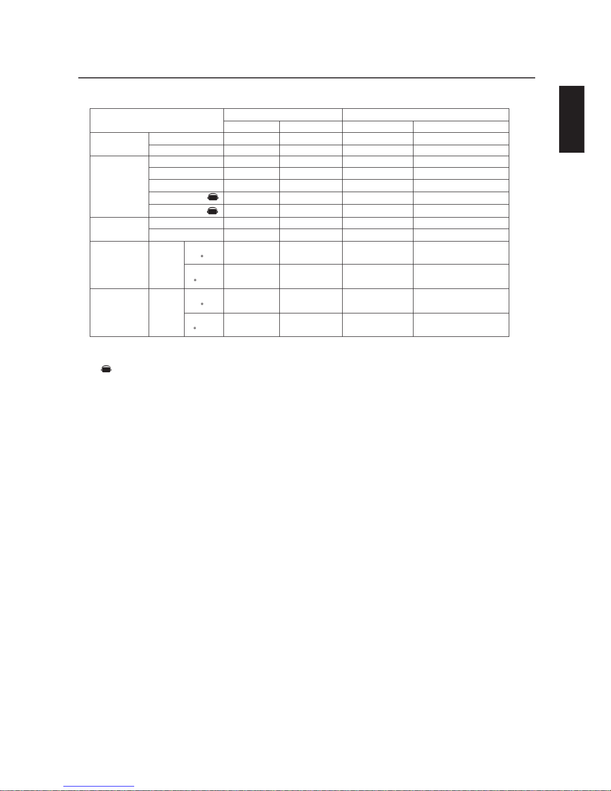
English-31
English
Using the LCD with a Personal Computer –continued
AV
Mark is an AV-unit function.
All AV functions are enabled when the AV-unit is installed.
AV
AV
Structure of the Read-command
POWER
Input
Picture mode
Temperature
of Internal
monitor
ASCII
HEX
ON
OFF(stand by)
RGB-1(DVI-D)
RGB-2(D-sub)
RGB-3(BNC)
Video
DVD/HD
Hi Bright
Standard
Around
Power
PCB
Around
Power
PCB
Function
vP
vP
vI
vI
vI
vI
vI
vM
vM
tcx1
tc1
tcx2
tc2
Data (Receive)
1
0
r1
r2
r3
v1
v2
p1
p2
(ex.) +25.0
(ex.)+25
(ex.)+30.5
(ex.)+31
Function
76 50
76 50
76 49
76 49
76 49
76 49
76 49
76 4D
76 4D
74 63 78 31
74 63 31
74 63 78 31
74 63 32
Data (Receive)
31
30
72 31
72 32
72 33
76 31
76 32
70 31
70 32
2B 20 32 35
2E 30
2B 20 32 35
2B 20 33 30 2E 35
2B 20 33 31
resolution
0.5 C
resolution
1 C
resolution
0.5 C
resolution
1 C
NOTE: For complete information please see file "External_Control_LCD4x10.pdf" on the CD-ROM.

English-32
40” or 46” diagonal screen size adds a new dimension to information display technology.
1366 x 768 resolution allows for crisp text and precise images.
XtraView
®
technology allows for wide-angle viewing.
DDC/CI capabilities allow control commands to be sent directly to the monitor through a standard PC or over an existing
network by a system administrator.
CableComp™ automatic long cable compensation prevents image quality degradation caused by long cable lengths.
User-friendly, efficient design features the currently proposed VESA-standard mounting and an overall lightweight
construction for easy transport and installation.
Optional detachable speakers deliver an enhanced multimedia experience with amazing sound quality.
Low power consumption and reduced heat emission lead to a lower total cost of ownership.
On Screen Manager (OSM
®
) puts you in complete control of display setting adjustments.
NEC’s quality and reliability provide peace of mind with a 1-year warranty (including backlight) and 24/7 customer
service and technical support.
Reduced Footprint: Provides the ideal solution for environments requiring superior image quality but with size and weight
reductions. The monitor’s small footprint and low weight allow it to be moved or transported easily from one location to
another.
AccuColor
®
Control System with sRGB allows you to change between the color settings on your display to match your
personal preference.
OmniColor™ Control System with sRGB color-matching uses 6-axis color data to ensure true-to-life color reproduction for
still images and real-time videos.
Plug and Play: The Microsoft
®
solution with the Windows®95/98/ME/2000/XP operating system facilitates
setup and installation by allowing
the monitor to send its capabilities (such as screen size and resolutions supported)
directly
to your computer, automatically optimizing display performance.
Intelligent Power Manager (IPM
®
) System provides innovative power-saving methods, saving two-thirds of your monitor
energy costs.
Multiple Frequency Technology automatically adjusts monitor to the display card’s scanning frequency, thus displaying
the resolution required.
FullScan® Capability allows you to use the entire screen area in most resolutions, significantly expanding image size.
VESA® Standard Mounting Interface allows users to connect their LCD monitor to any VESA standard third party mount-
ing arm or bracket. Allows for the monitor to be mounted on a wall or an arm using any third party compliant device.
NEC recommends using mounting interface that comply with UL1678 standard in North America.
DVI-D: The digital-only subset of DVI created by the Digital Display Working Group (DDWG) for digital connections
between computers and displays. As a digital-only connector, analog support is not provided off a DVI-D connector. As
a DVI-based digital only connection, only a simple adapter is necessary for compatibility between DVI-D and other DVIbased digital connectors such as DFP and P&D.
TILE MATRIX, TILE COMP: Allows multiple screens to display one image, tiled over several stacked monitors that are and
compensates within the image for the bezel width.
ZOOM: Expands the image individually for horizontal and vertical direction.
RS-232C daisy chain: you can control the multiple monitors by controller or wireless remote controller.
Self-diagnosis: If an internal error should occur, a failure state will be indicated.
Features

English
English-33
Troubleshooting
No picture
• The signal cable should be properly connected to the display card/computer.
• The display card should be properly seated in its slot.
• Front Power Switch and computer power switch should be in the ON position.
• Check to make sure that a supported mode has been selected on the display card or system being used. (Please consult display card
or system manual to change graphics mode.)
• Check the monitor and your display card with respect to compatibility and recommended settings.
• Check the signal cable connector for bent or pushed-in pins.
Power Button does not respond
• Unplug the power cord of the monitor from the AC outlet to turn off and reset the monitor.
Image persistence
• Please be aware that LCD Technology may experience a phenomena known as Image Persistence. Image Persistence occurs when a
residual or “ghost” image of a previous image remains visible on the screen. Unlike CRT monitors, LCD monitors’ image persistence is not
permanent, but constant images being displayed for a long period of time should be avoided. To alleviate image persistence, turn off the
monitor for as long as the previous image was displayed. For example, if an image was on the monitor for one hour and a residual image
remains, the monitor should be turned off for one hour to erase the image.
NOTE: As with all personal display devices, NEC-Mitsubishi Electronics Display recommends using a moving screen saver at regular
intervals whenever the screen is idle or turning off the monitor when not in use.
Image is unstable, unfocused or swimming is apparent
• Signal cable should be properly attached to the LCD monitor, computer, or other input device.
• Use the OSM screen controls to focus and adjust display by increasing or decreasing the clock phase total. When the display mode
is changed, the OSM Image Adjust settings may need to be readjusted.
• Check the monitor and your display card with respect to compatibility and recommended signal timings.
• If your text is garbled, change the video mode to non-interlace and use 60Hz refresh rate.
Image of component signal is greenish
• Check to see if the DVD/HD input connector is selected.
LED on monitor is not lit (no green or red color can be seen)
• Main Power Switch should be in the ON position and power cord should be connected.
• Make certain the computer is not in a power-saving mode (touch the keyboard or mouse).
Red LED on monitor is blinking
•A certain failure might have occurred, please contact your nearest authorized NEC-Mitsubishi Electronics Display service facility.
Display image is not sized properly
• Use the OSM screen controls to increase or decrease the clock total.
• Check to make sure that a supported mode has been selected on the display card or system being used. (Please consult display card
or system manual to change graphics mode.)
Selected resolution is not displayed properly
• Use OSM information to enter Information menu and confirm that the appropriate resolution has been selected. If not, select
appropriate resolution.
No Sound
• Check to see if speaker cable is properly connected.
• Check to see if mute is activated.
• Check to see if volume is set at minimum.
Remote Control is not available
•Test the Remote Control’s batteries for strength/life.
• Check if the batteries are inserted correctly.
• Check if the Remote Control is pointed at the monitor’s remote sensor.
“SCHEDULE” / ”OFF TIMER” functions not working properly
• The “SCHEDULE” function will be disabled when the “OFF TIMER” is set.
• If the “OFF TIMER” function is enabled and the power to the LCD monitor is turned off or if the power supply is interrupted unexpectedly,
then the OFF TIMER will be reset.
Light vertical or horizontal stripes may appear depending on different display patterns. This is no product fault or degradation.

English-34
References
NEC-Mitsubishi Monitor Customer Service & Support
Customer Service and Technical Support:
(800) 632-4662
Fax: (800) 695-3044
Parts and Accessories/
Macintosh Cable Adapter: (888) NEC-MITS [888-632-6487]
Warranty Information www.necmitsubishi.com/warranty
Online Technical Support www.necmitsubishi.com/support
Sales and Product Information
Sales Information Line: (888) NEC-MITS [888-632-6487]
Canadian Customers: (866) 771-0266, Ext#: 4037
Government Sales: (800) 284-6320
Government Sales email: gov@necmitsubishi.com
Electronic Channels
World Wide Web: http://www.necmitsubishi.com
Product Registration: http://www.necmitsubishi.com/productregistration
European Operations: http://www.nec-mitsubishi.com
Drivers and Downloads:
http://
www.necmitsubishi.com/downloads

English-35
English
LCD Module
External speaker output inpedance
Frequency
Pixel Clock
Viewable Size
Input Signal
Pixel Pitch
Resolution
Color
Brightness
Contrast ratio
Viewing Angle
Horizontal
Vertical
PC Input
Video
Sync
Input terminal
VIDEO Input
Analog Input
(40" / 101.6 cm diagonal)
0.648mm
1366 x 768 dots
Over 16 million colors (depending on video card used)
500cd/m2 (Typ.)
800 : 1
Up 85 / Down 85 / Left 85 / Right 85 (typ) @ CR >10
Rating 7W x 7W (8 Ohm)
15.625/15.734kHz , 31.5kHz - 91.1kHz
50Hz, 60Hz to 85Hz
25.0MHz - 162.0MHz
885.168 x 497.64mm
Analog RGB 0.7V p-p
Input Impedance 75 Ohm
Composite sync on Green Video
: 0.3Vp-p Nega (video 0.7Vp-p Positive)
Separate : TTL level (Positive / Negative), Input Impedance 2.2k Ohm
BNC (R,G,B,H,V) 15pin Mini D-sub
Composite 1.0V p-p Input Impedance 75 Ohm BNC and RCA-INPUT
Y/C Y:0.7V p-p C:0.283V p-p Input Impedance 75 Ohm S-TERMINAL-INPUT
Component 1.0/0.7V p-p Input Impedance 75 Ohm BNC-INPUT
RCA PIN-JACK L/R 2INPUT, STEREO Mini Jack 1INPUT
9 Pin Mini D-sub
9 Pin Mini D-sub (with daisy chain)
2.3 - 0.95A @ 100-240VAC, 50/60Hz
5 - 40 deg C
20 - 80% (without condensation)
-20 - 60 deg C
10 - 90% (without condensation) / 90% - 3.5% x (temp - 40 deg C) regarding over 40 deg C
981.8 (W) x 579.8 (H ) x 140 (D) mm (without Stand), 981.8 (W) x 611.1 (H) x 330 (D) mm (with Stand)
1147 (W) x 761(H) x 312 (D) mm
57.3 lbs / 26.0kg (without Stand) 60.6 lbs / 27.5kg (with Stand)
77.2 lbs / 35.0kg
3 x 200mm x 200mm (8 Holes)
2 x 200mm x 200mm (6 Holes)
UL 60950-1/CSA C22.2 No.60950-1/ TUV-GS/EN60950-1
FCC-B/DOC-B/EN55022-A/EN55024/EN61000-3-2/EN61000-3-3/CE
VESA DPM
VESA DDC2B, DDC/CI
NTSC / PAL / SECAM / 4.43NTSC / PAL60
HDTV: 480i, 480p, 720p, 1080i,
User's manual, Power Cord, Video Signal Cable, Remote Control, AA Battery x 2, Clamper x 3, Screw x 4, CD-ROM
Stand x 2, Thumbscrew for stand x 2, Main switch cover x 1
Digital Input
31.5kHz - 91.1kHz
TMDS
DVI-D (Digital)
AUDIO Input
RS232C In
Out
Temperature
Humidity
Temperature
Humidity
Net
Gross
Net
Gross
Power Supply
Operational
Environment
Storage
Environment
Dimension
Weight
VESA compatible arm
mounting interface
Complied Regulatory and
Guidelines
Power Management
Plug & Play
Resolutions Supported
Accessories
Ferrite Core x 2, Band x 2, Speaker plug x 1set
640 x 480 at 60Hz to 85Hz
800 x 600 at 50Hz, 60Hz to 85Hz
1024 x 768 at 50Hz, 60Hz to 85Hz
1280 x 768 at 50Hz, 60Hz to 85Hz
1360 x 768 at 50Hz, 60Hz* to 85Hz
1366 x 768 at 50Hz, 60Hz* to 85Hz
1280 x 1024 at 60Hz to 85Hz
1600 x 1200 at 60Hz .....Maximum Resolution
*Recomended Resolution (Depends of the video card used.)
Specifications - LCD4010
Product Specifications
NOTE: Technical specifications are subject to change without notice.
Mark is an AV-unit function.
All AV functions are enabled when the AV-unit is installed.
AV
AV
AV
AV

English-36
Specifications - LCD4610
LCD Module
External speaker output inpedance
Frequency
Pixel Clock
Viewable Size
Input Signal
Pixel Pitch
Resolution
Color
Brightness
Contrast ratio
Viewing Angle
Horizontal
Vertical
PC Input
Video
Sync
Input terminal
VIDEO Input
Analog Input
(46" / 116.8 cm diagonal)
0.7455mm
1366 x 768 dots
Over 16 million colors (depending on video card used)
500cd/m2 (Typ.)
800 : 1
Up 85 / Down 85 / Left 85 / Right 85 (typ) @ CR >10
Rating 7W x 7W (8 Ohm)
15.625/15.734kHz , 31.5kHz - 91.1kHz
50Hz, 60Hz to 85Hz
25.0MHz - 162.0MHz
1018.4 x 572.50mm
Analog RGB 0.7V p-p
Input Impedance 75 Ohm
Composite sync on Green Video
: 0.3Vp-p Nega (video 0.7Vp-p Positive)
Separate : TTL level (Positive / Negative), Input Impedance 2.2k Ohm
BNC (R,G,B,H,V) 15pin Mini D-sub
Composite 1.0V p-p Input Impedance 75 Ohm BNC and RCA-INPUT
Y/C Y:0.7V p-p C:0.283V p-p Input Impedance 75 Ohm S-TERMINAL-INPUT
Component 1.0/0.7V p-p Input Impedance 75 Ohm BNC-INPUT
RCA PIN-JACK L/R 2INPUT, STEREO Mini Jack 1INPUT
9 Pin Mini D-sub
9 Pin Mini D-sub (with daisy chain)
2.6 - 1.1A @ 100-240VAC, 50/60Hz
5 - 40 deg C
20 - 80% (without condensation)
-20 - 60 deg C
10 - 90% (without condensation) / 90% - 3.5% x (temp - 40 deg C) regarding over 40 deg C
1112.8 (W) x 655.8 (H ) x 140 (D) mm (without Stand), 1112.8 (W) x 687.1 (H) x 351 (D) mm (with Stand)
1278 (W) x 837(H) x 312 (D) mm
68.3 lbs / 31.0kg (without Stand) 72.3 lbs / 32.8kg (with Stand)
89.3 lbs / 40.5kg
3 x 200mm x 200mm (8 Holes)
2 x 200mm x 200mm (6 Holes)
UL 60950-1/CSA C22.2 No.60950-1/ TUV-GS/EN60950-1
FCC-B/DOC-B/EN55022-A/EN55024/EN61000-3-2/EN61000-3-3/CE
VESA DPM
VESA DDC2B, DDC/CI
NTSC / PAL / SECAM / 4.43NTSC / PAL60
HDTV: 480i, 480p, 720p, 1080i,
User's manual, Power Cord, Video Signal Cable, Remote Control, AA Battery x 2, Clamper x 3, Screw x 4, CD-ROM
Stand x 2, Thumbscrew for stand x 2, Main switch cover x 1
Digital Input
31.5kHz - 91.1kHz
TMDS
DVI-D (Digital)
AUDIO Input
RS232C In
Out
Temperature
Humidity
Temperature
Humidity
Net
Gross
Net
Gross
Power Supply
Operational
Environment
Storage
Environment
Dimension
Weight
VESA compatible arm
mounting interface
Complied Regulatory and
Guidelines
Power Management
Plug & Play
Resolutions Supported
Accessories
Ferrite Core x 2, Band x 2, Speaker plug x 1set
640 x 480 at 60Hz to 85Hz
800 x 600 at 50Hz, 60Hz to 85Hz
1024 x 768 at 50Hz, 60Hz to 85Hz
1280 x 768 at 50Hz, 60Hz to 85Hz
1360 x 768 at 50Hz, 60Hz* to 85Hz
1366 x 768 at 50Hz, 60Hz* to 85Hz
1280 x 1024 at 60Hz to 85Hz
1600 x 1200 at 60Hz .....Maximum Resolution
*Recomended Resolution (Depends of the video card used.)
Product Specifications
NOTE: Technical specifications are subject to change without notice.
Mark is an AV-unit function.
All AV functions are enabled when the AV-unit is installed.
AV

English-37
English
Pin Assignment
oNniPemaN
1deRlangiSoediV
2neerGlangiSoediV
3eulBlangiSoediV
4DNG
5DNG-CDD
6DNG-deR
7DNG-neerG
8DNG-eulB
9)CDD(V5+
01DNG-CNYS
11DNG
21ADS-CDD
31CNYS-H
41CNYS-V
51LCS-CDD
oNniPemaN
1CN
2DXR
3DXT
4CN
5DNG
6CN
7STR
8STC
9CN
oNniPemaN
1DNG
2DNG
3)ecnanimuL(Y
4)amorhC(C
1-2XT9-1XT71-0XT
2+2XT01+1XT81+OXT
3)4XT/2XT(dleihS11)3XT/1XT(dleihS91)5XT/PXT(dleihS
4CN21CN02CN
5CN31CN12CN
6kcolClaireS-CDD41)*rewop5+22)CXT(dleihS
7ataDlaireS-CDD51)V5+(dnuorG32+CXT
8CN61tceteDgulPtoH42-CXT
1) Analog RGB Input (MiniDsub): R G B 2
2) S-VIDEO input: V I D E O
3) Digital RGB Input (DVI-D): R G B 1
4) RS-232 input

English-38
Limited Warranty
NEC-Mitsubishi Electronics Display of America, Inc. (hereinafter “NMD-A”) warrants this Product to be free
from defects in material and workmanship and, subject to the conditions set forth below, agrees to repair or
replace (at NMD-A’s sole option) any part of the enclosed unit which proves defective for a period of one (1)
year from the date of first consumer purchase. Spare parts are warranted for ninety (90) days. Replacement
parts or unit may be new or refurbished and will meet specifications of the original parts or unit.
This warranty gives you specific legal rights and you may also have other rights, which vary from state to state.
This warranty is limited to the original purchaser of the Product and is not transferable. This warranty covers
only NMD-A-supplied components. Service required as a result of third party components is not covered under
this warranty. In order to be covered under this warranty, the Product must have been purchased in the U.S.A.
or Canada by the original purchaser. This warranty only covers Product distribution in the U.S.A. or Canada
by NMD-A. No warranty service is provided outside of the U.S.A. or Canada. Proof of Purchase will be
required by NMD-A to substantiate date of purchase. Such proof of purchase must be an original bill of sale
or receipt containing name and address of seller, purchaser, and the serial model number of the product.
It shall be your obligation and expense to have the Product shipped, freight prepaid, or delivered to the
authorized reseller from whom it was purchased or other facility authorized by NMD-A to render the services
provided hereunder in the original package. All Products returned to NMD-A for service MUST have prior
approval, which may be obtained by calling 1-800-632-4662. The Product shall not have been previously
altered, repaired, or serviced by anyone other than a service facility authorized by NMD-A to render such
service, the serial number of the product shall not have been altered or removed. In order to be covered by
this warranty the Product shall not have been subjected to displaying of fixed images for long periods of time
resulting in image persistence (afterimage effects), accident, misuse or abuse or operated contrary to the
instructions contained in the User’s Manual. Any such conditions will void this warranty.
NMD-A SHALL NOT BE LIABLE FOR DIRECT, INDIRECT, INCIDENTAL, CONSEQUENTIAL, OR OTHER TYPES
OF DAMAGES RESULTING FROM THE USE OF ANY NMD-A PRODUCT OTHER THAN THE LIABILITY
STATED ABOVE. THESE WARRANTIES ARE IN LIEU OF ALL OTHER WARRANTIES EXPRESS OR IMPLIED,
INCLUDING, BUT NOT LIMITED TO, THE IMPLIED WARRANTIES OF MERCHANTABILITY OR FITNESS FOR
A PARTICULAR PURPOSE. SOME STATES DO NOT ALLOW THE EXCLUSION OF IMPLIED WARRANTIES
OR THE LIMITATION OR EXCLUSION OF LIABILITY FOR INCIDENTAL OR CONSEQUENTIAL DAMAGES SO
THE ABOVE EXCLUSIONS OR LIMITATIONS MAY NOT APPLY TO YOU.
This Product is warranted in accordance with the terms of this limited warranty. Consumers are cautioned that
Product performance is affected by system configuration, software, the application, customer data, and
operator control of the system, among other factors. While NMD-A Products are considered to be compatible
with many systems, specific functional implementation by the customers of the Product may vary. Therefore,
suitability of a Product for a specific purpose or application must be determined by consumer and is not
warranted by NMD-A.
For the name of your nearest authorized NEC-Mitsubishi Electronics Display service facility, contact NECMitsubishi Electronics Display of America at 1-800-632-4662.

English-39
English
Declaration of the Manufacturer
We hereby certify that the color monitor
MultiSync
®
LCD4010™ (L404G6) /
MultiSync
®
LCD4610™ (L464G7) is in
compliance with
Council Directive 73/23/EEC:
– EN 60950-1
Council Directive 89/336/EEC:
— EN 55022
— EN 61000-3-2
— EN 61000-3-3
— EN 55024
and marked with
NEC-Mitsubishi Electric Visual
Systems Corporation
4-13-23, Shibaura,
Minato-Ku
Tokyo 108-0023, Japan
PROPRIETARY NOTICE AND LIABILITY DISCLAIMER
The information disclosed in this document, including all designs and related materials, is the valuable property of NEC-Mitsubishi
Electronics Display of America and/or its licensors, as appropriate, reserve all patent, copyright and other proprietary rights to this
document, including all design, manufacturing, reproduction, use and sales rights thereto, except to the extent said rights are expressly
granted to others.
The NEC-Mitsubishi Electronics Display of America product(s) discussed in this document are warranted in accordance with the terms
of the Limited Warranty Statement accompanying each product. However, actual performance of each such product is dependent
upon factors such as system configuration, customer data and operator control. Since implementation by customers of each product
may vary, the suitability of specific product configurations and applications must be determined by the customer and is not warranted
by NEC-Mitsubishi Electronics Display of America.
To allow for design and specification improvements, the information in this document is subject to change at any time without notice.
Reproduction of this document or portions thereof without prior approval of NEC-Mitsubishi Electronics Display of America is
prohibited.
DECLARATION OF CONFORMITY
This device complies with Part 15 of FCC Rules. Operation is subject to the following two conditions. (1) This device may not cause
harmful interference, and (2) this device must accept any interference received, including interference that may cause undesired
operation.
Type of Product: Computer Monitor
Equipment Classification: Class B Peripheral
Model: MultiSync LCD4010 (L404G6) / MultiSync LCD4610 (L464G7)
We hereby declare that the equipment specified above
conforms to the technical standards as specified in the FCC Rules.
Windows is a registered trademark of Microsoft Corporation. NEC is a registered trademark of NEC Corporation. All other brands
and product names are trademarks or registered trademarks of their respective owners.
NEC MultiSync® LCD4010/MultiSync® LCD4610
U.S. Responsible Party: NEC-Mitsubishi Electronics Display of America, Inc.
Address: 500 Park Blvd, Suite 1100
Itasca, Illinois 60143
Tel. No.: (630) 467-3000
Part No. 15503632
Printed in China
NMDA
021605
 Loading...