How it Works
Log In / Sign Up
Buy Points
How it Works
FAQ
Contact Us
Questions and Suggestions
Users
Nec
Loading...
M
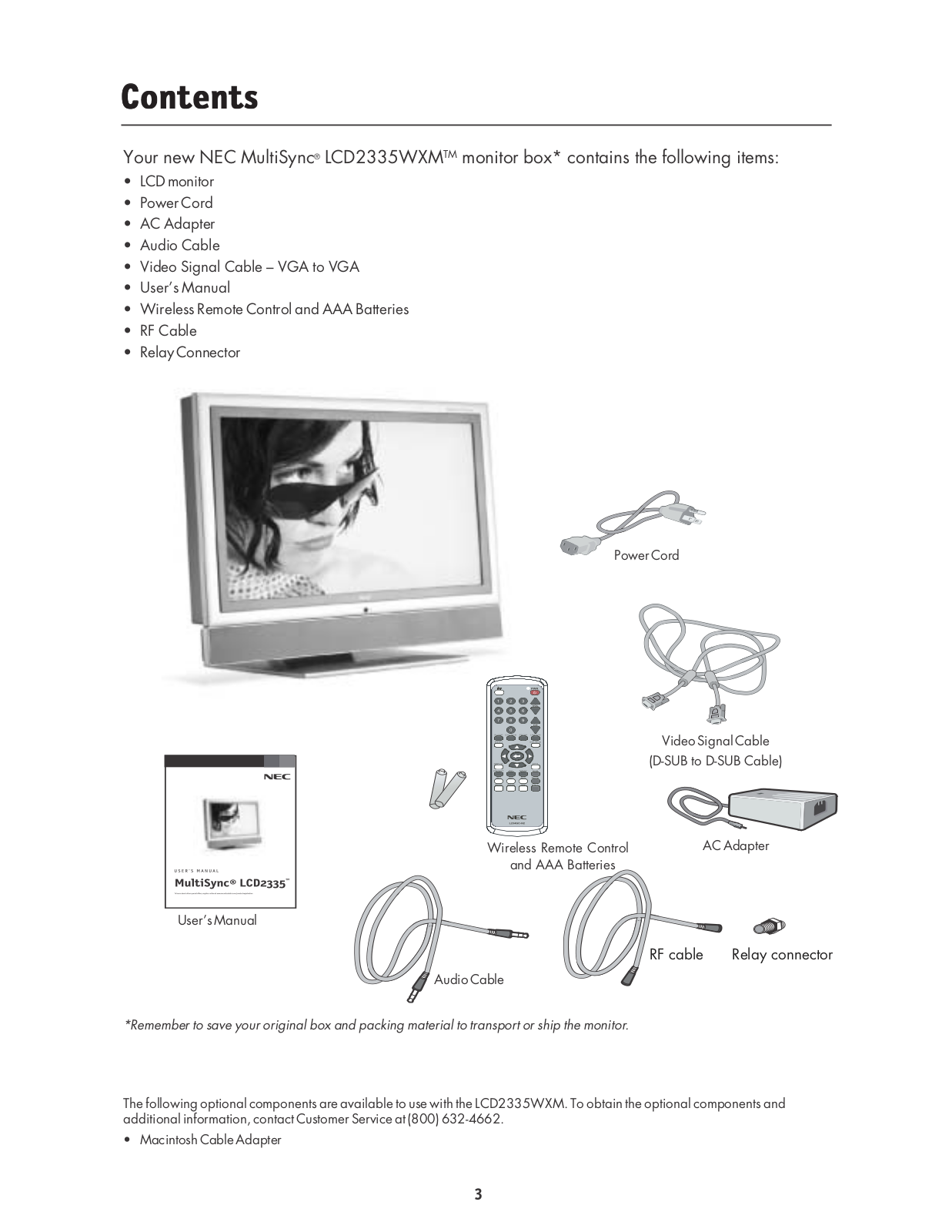
MultiSync LCD195WXM
6
MultiSync LCD1960NX
3
MultiSync LCD1960NXi
2
MultiSync LCD1960NXi-A
MultiSync LCD1970GX
MultiSync LCD1970NX
8
MultiSync LCD1970NXp
4
MultiSync LCD1970V
5
MultiSync LCD1970VX
5
MultiSync LCD1980FXi
4
MultiSync LCD1980FXim
MultiSync LCD1980SX
6
MultiSync LCD1980SXi
4
MultiSync LCD1990FX
4
MultiSync LCD1990FXp
4
MultiSync LCD1990SX
2
MultiSync LCD1990SXi
3
MultiSync LCD1990SXi BK
MULTISYNC LCD1990SXP
2
MultiSync LCD1990SXp-BK
MultiSync LCD2000
MultiSync LCD2010
7
MultiSync LCD2010X
3
MultiSync LCD205WNXM
2
MultiSync LCD205WXM
3
MULTISYNC LCD2060NX
4
MultiSync LCD2060NX-BK
MultiSync LCD2070NX
8
MultiSync LCD2070VX
4
MultiSync LCD2070VX-BK
MultiSync LCD2070wNx
5
MultiSync LCD2070WNX-BK
MultiSync LCD2080UX
5
MultiSync LCD2080UX -BKA
MultiSync LCD2080UXi
3
MultiSync LCD2080UXi-BK
MultiSync LCD2090UXi
3
MultiSync LCD2090UXi-BK
MultiSync LCD2110
4
MultiSync LCD2170NX
8
MultiSync LCD2170NX-BK-2
MultiSync LCD2180UX
6
MultiSync LCD2180WG-LED
MultiSync LCD2180WGLEDSV
MULTISYNC LCD2180 WideGamut LED
MultiSync LCD2190UXi
3
MultiSync LCD2190UXp
5
MultiSync LCD225WNX
2
MultiSync LCD225WNXM
2
MultiSync LCD225WXM
2
MULTISYNC LCD2335WXM
3
MultiSync LCD2470WNX
6
MultiSync LCD2470WVX
5
MultiSync LCD2490W2-BK-SV
MultiSync LCD2490WUXi
2
MultiSync LCD2490WUXi2
3
MultiSync LCD2490WUXi2-BK
MultiSync LCD2690W2-BK-SV
MultiSync LCD2690WUXi
4
MultiSync LCD2690WUXi2
5
MultiSync LCD3090W-BK-SV
MultiSync LCD3090WQXi
4
MultiSync LCD3210
MultiSync LCD3210-BK-IT
2
MultiSync LCD3215
5
MultiSync LCD3735WXM
MultiSync LCD400
MultiSync LCD400V
MultiSync LCD4010
6
MultiSync LCD4010-BK-IT
MULTISYNC LCD4020
6
MultiSync LCD4020-BK-AV
MultiSync LCD4020-TMX4
MultiSync LCD4215
7
MultiSync LCD4215R
MultiSync LCD4610
6
MultiSync LCD4610-BK-IT
MultiSync LCD4615
MultiSync LCD4620
5
MultiSync LCD4620-BK-AV
MultiSync LCD5220
3
MultiSync LCD5220-TMX4
MultiSync LCD5710
4
MultiSync LCD6520L
2
MultiSync LCD6520L-BK-AV
2
MultiSync LCD6520P
MultiSync LCD6520P-BK-AV
MultiSync LCD8205
3
MultiSync LCD8205-P
5
MultiSync LT100
2
MultiSync LT140
3
MultiSync LT150
MultiSync LT154
MultiSync LT155
MultiSync LT156
MultiSync LT245
2
MultiSync LT280
3
MultiSync LT380
2
MultiSync LT80
MultiSync LT84
2
Loading...
Loading...
Nothing found
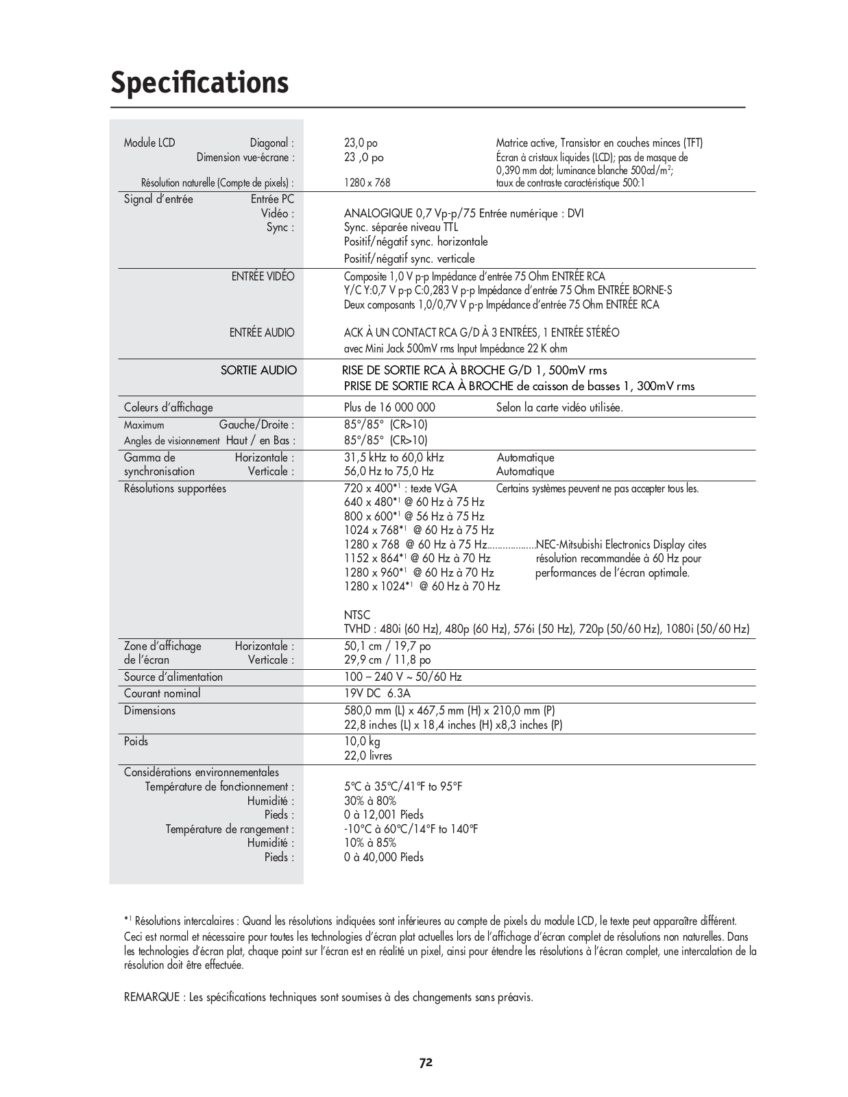
MULTISYNC LCD2335WXM
Dimensional Drawing
1 pgs
152.72 Kb
0
User Guide
80 pgs
4.43 Mb
0
User Manual
41 pgs
4.62 Mb
0
Table of contents
Loading...
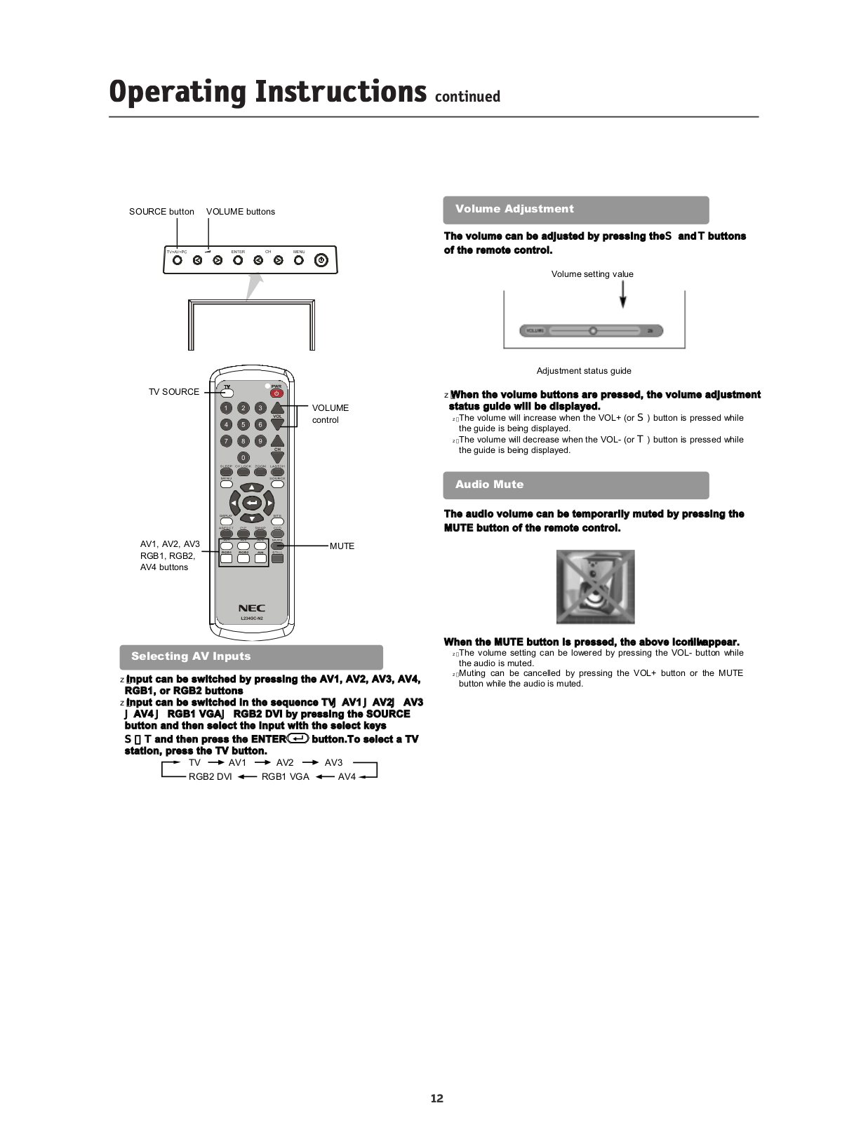
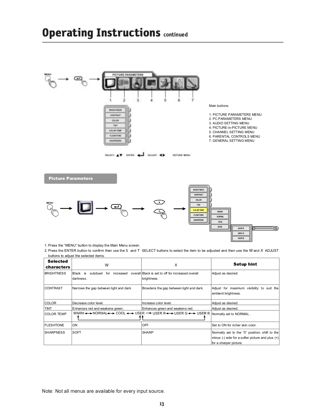
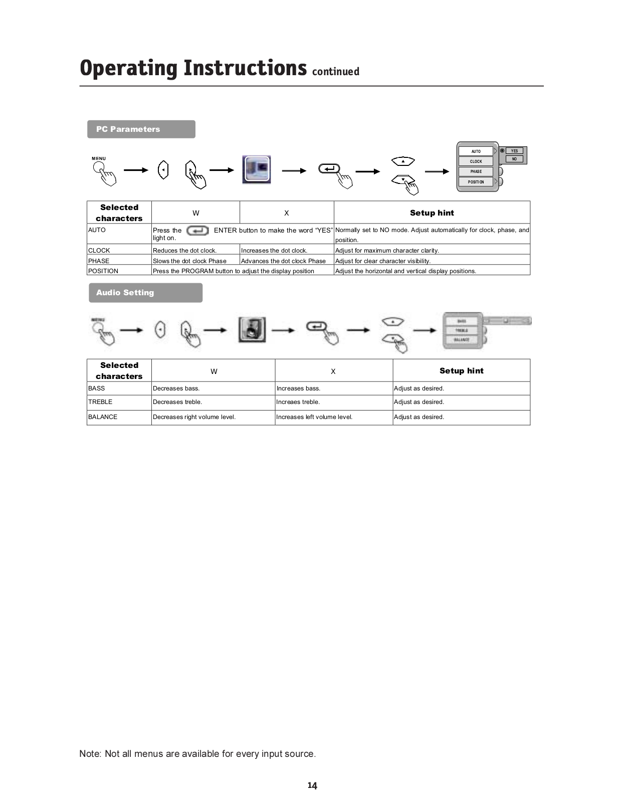
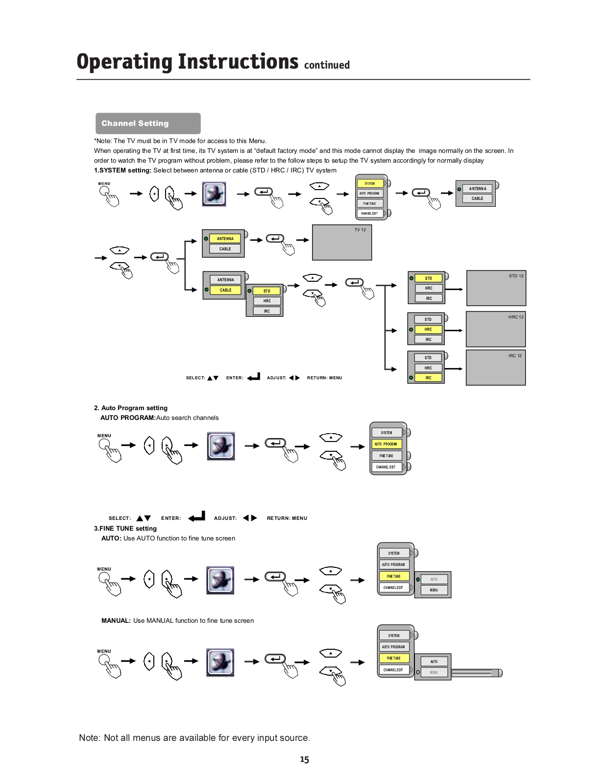
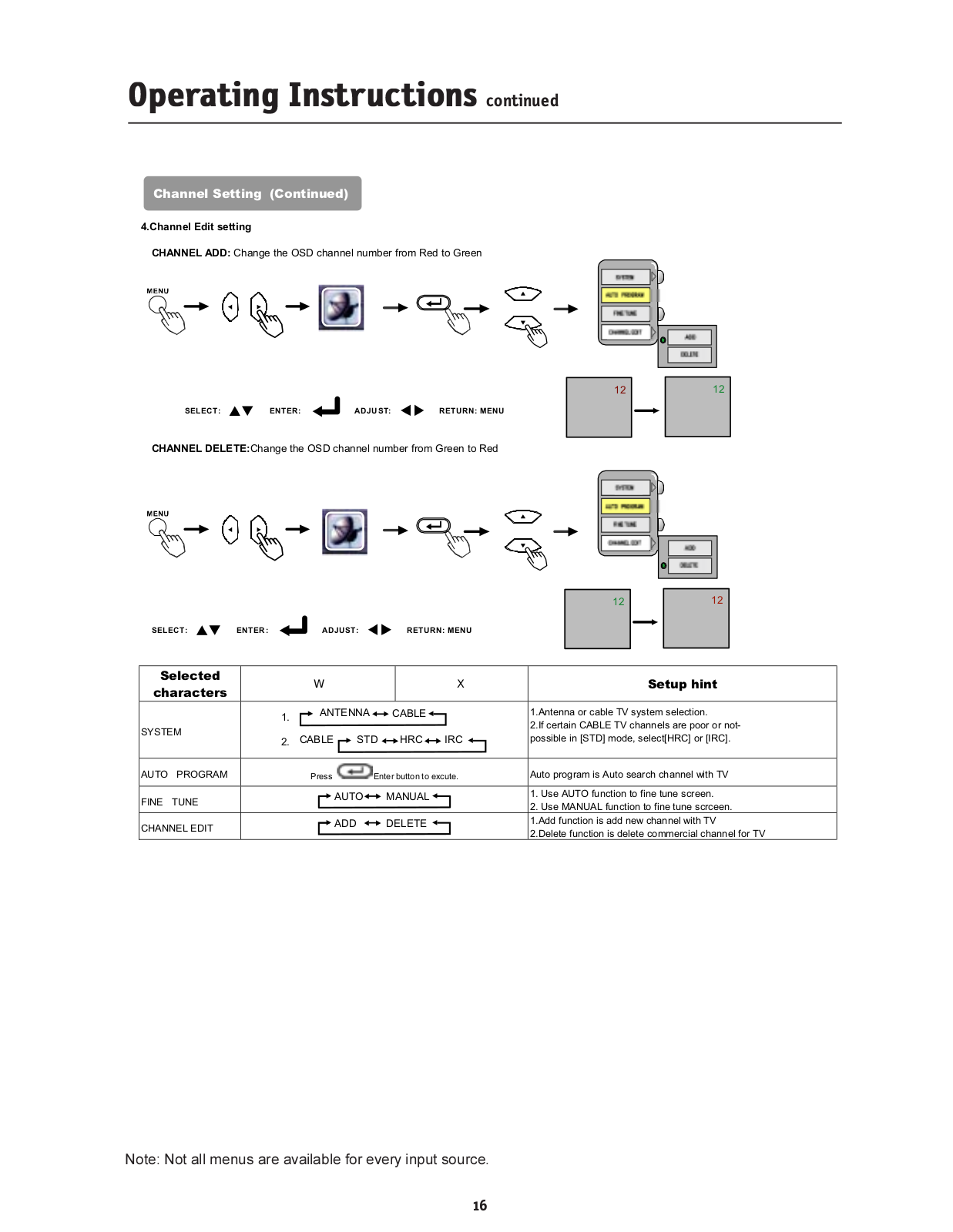
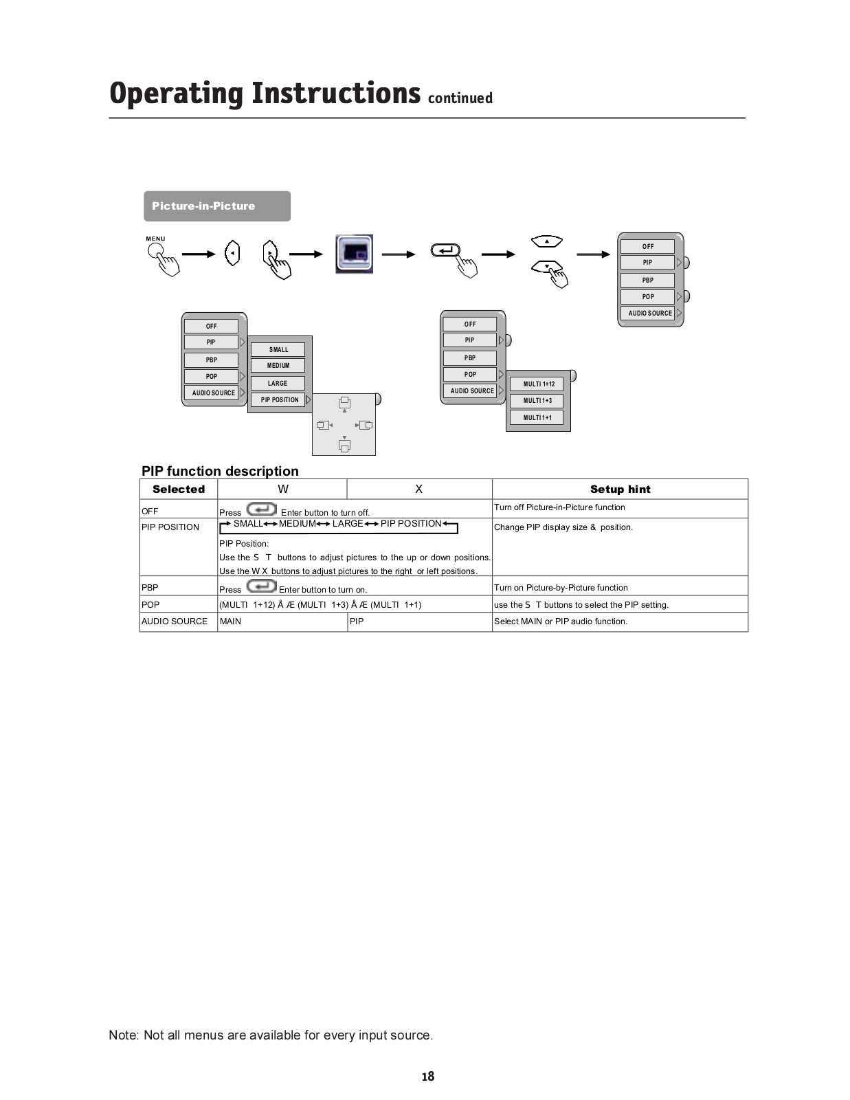
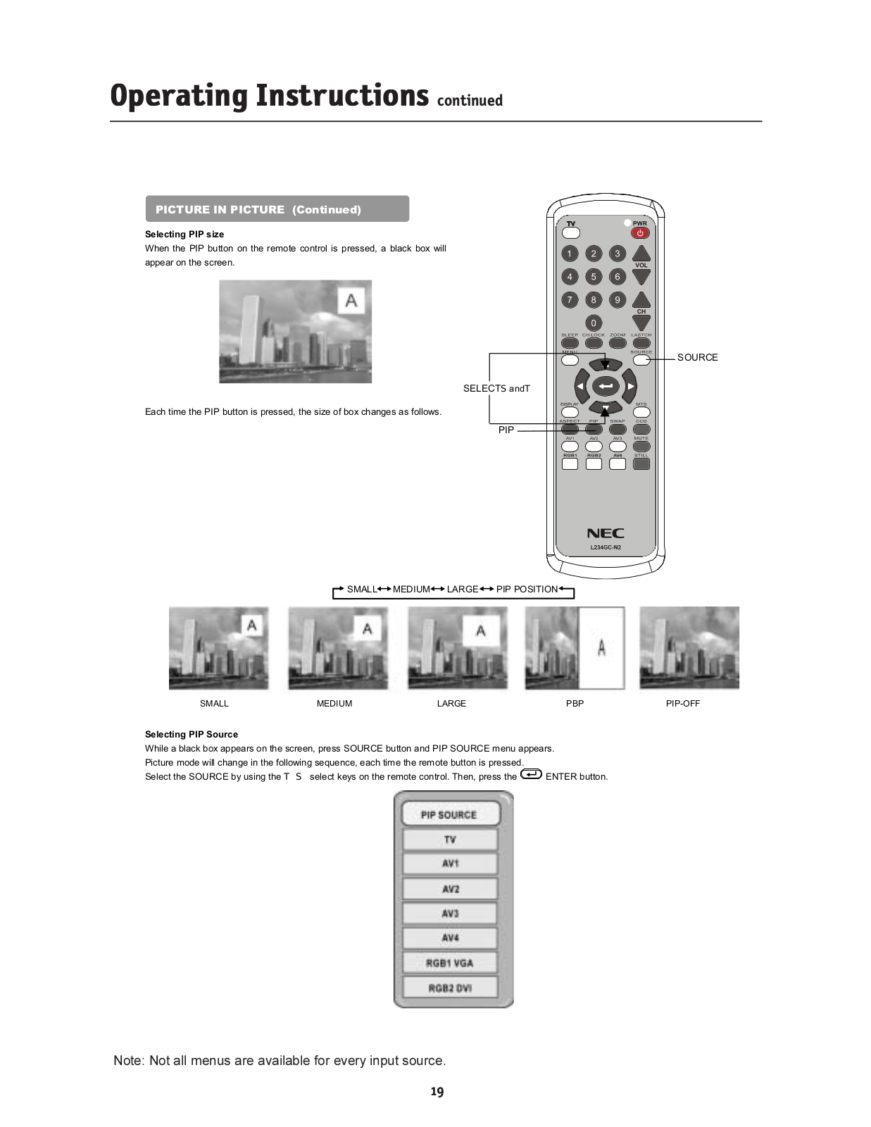
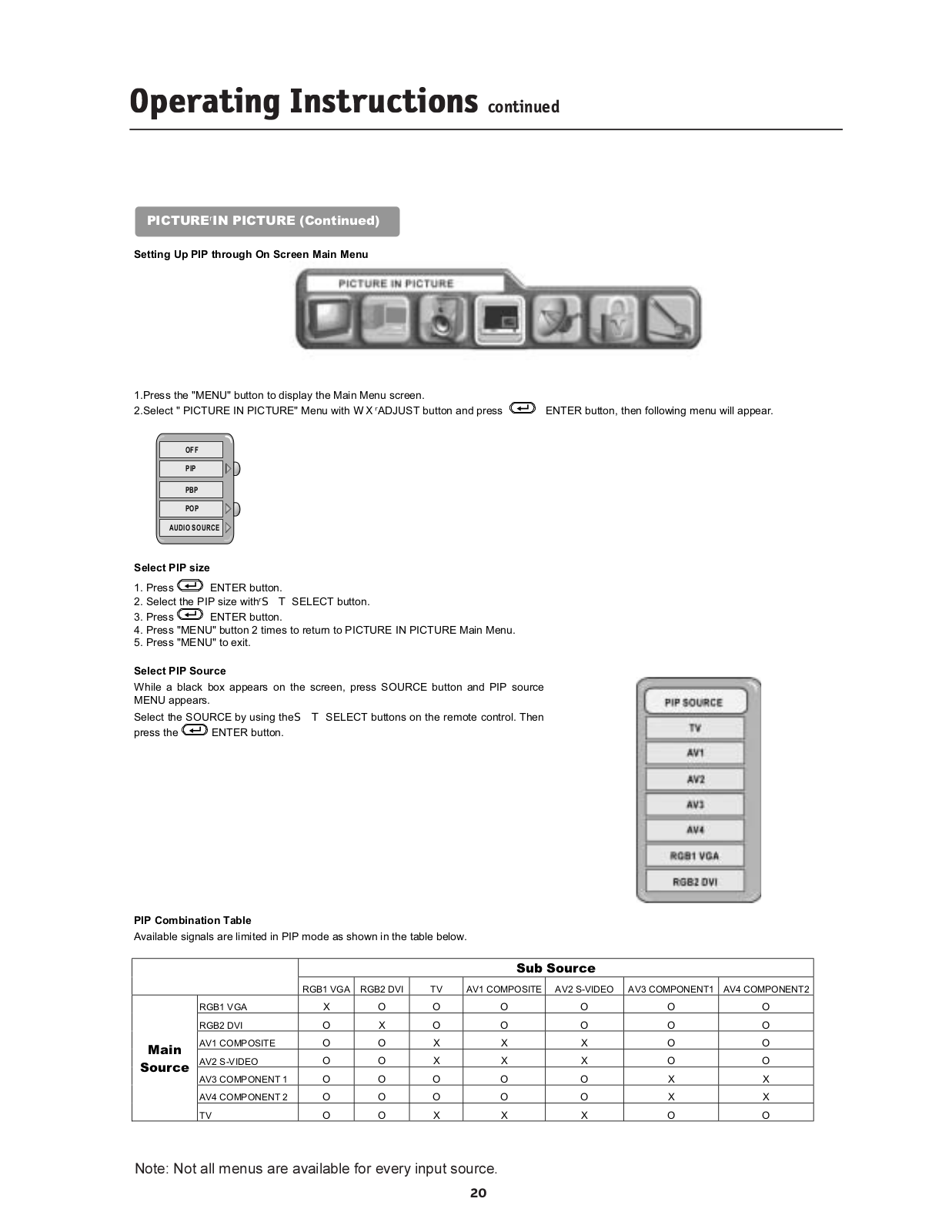
Nec MULTISYNC LCD2335WXM User Guide
...
Nec User Guide
Download
Specifications and Main Features
Frequently Asked Questions
User Manual
Download
Loading...
+
hidden pages
Unhide
You need points to download manuals.
1 point = 1 manual.
You can buy points or you can get point for every manual you upload.
Buy points
Upload your manuals
 Loading...