


LCD1990SXp
To learn about other special offers, register online at www.necdisplay.com.
Pour en savoir plus long sur d’autres offres spéciales, inscrivez-vous en
ligne à www.necdisplay.com.
Para informarse sobre otras ofertas especiales, regístrese en línea en
www.necdisplay.com

Warning
..................................................................................................................................................
1
Contents
................................................................................................................................................
Quick Start
...........................................................................................................................................
3
Controls
.................................................................................................................................................
9
Advanced OSM Controls
...................................................................................................................
16
.............................................................................................
...................................................................................................
............................................................................................................................
....................................................................................................................................
..............................................................................................................................................
................................................................................................................................
..........................................................................................................................................
..............................................................................................................................
................................................................................................................................................
..................................................................
...............................................................................................................................................
......................................................................................................................................
........................................................................................................................................
..................................................................................................
..............................................................
....................................................................................
................................................................................................................
.................................................................................................................................
.............................................................................................................................................
..........................................................................................................................................
.........................................................................................................................................
................................................................................................................................
..................................................................................................................................................
..................
........................................................................................................................................
..........................................................................................................................................
.......................................................................................................................................
.............................................................................................................................................
..............................................................................................................
.............................................................................................
.....................................................................................................
.............................................................................................................................
..................................................................................................................................
117
.................................................................................................................................
...................................................................................................................
.......................................................................................................................................
............................................................................................................................
................................................................................................................................................
...........................................................

1
WALL SOCKET. TO FULLY DISENGAGE THE POWER TO THE UNIT, PLEASE DISCONNECT THE POWER
CORD FROM THE AC OUTLET. DO NOT REMOVE COVER (OR BACK). NO USER SERVICEABLE PARTS
INSIDE. REFER SERVICING TO QUALIFIED SERVICE PERSONNEL.
This
symbol warns user that uninsulated voltage within the unit may have suffi cient magnitude to
cause electric shock. Therefore, it is dangerous to make any kind of contact with any part inside this
symbol warns user that uninsulated voltage within the unit may have suffi cient magnitude to
symbol warns user that uninsulated voltage within the unit may have suffi cient magnitude to
unit.
This symbol alerts the user that important literature concerning the operation and maintenance of this
unit has been included. Therefore, it should be read carefully in order to avoid any problems.
This symbol alerts the user that important literature concerning the operation and maintenance of this
This symbol alerts the user that important literature concerning the operation and maintenance of this
WARNING
CAUTION
Interference-Causing Equipment Regulations.
according to
TM
(L195RR) color monitor
(1)
(2) Please use the supplied shielded video signal cable, 15-pin mini D-SUB to
DVI-A cable, or DVI-D to DVI-D cable.
Use of other cables and adapters may cause interference with radio and
television reception.
• Reorient or relocate the receiving antenna.
• Increase the separation between the equipment and receiver.
• Reorient or relocate the receiving antenna.
• Reorient or relocate the receiving antenna.
• Connect the equipment into an outlet on a circuit different from that to which the receiver
• Increase the separation between the equipment and receiver.
• Increase the separation between the equipment and receiver.
is connected.
• Consult your dealer or an experienced radio/TV technician for help.
Washington, D.C., 20402, Stock No. 004-000-00345-4.

2
Your new
MultiSync
LCD monitor box* should

3
LCD monitor to your system,
signal cable to the connector of the display card in your system
(Figure A.1). Tighten all screws.
For a PC with Analog output: Connect the 15-pin mini D-SUB to DVI-A signal
cable to the connector of the display card in your system (Figure A.2).
For the MAC: Connect the MultiSync Macintosh cable adapter to the
computer, then attach the 15-pin mini D-SUB signal cable to the MultiSync
Macintosh cable adapter (Figure B.1).
NOTE: Some Macintosh systems do not require a
Macintosh cable adapter.
NOTE: To obtain the MultiSync Macintosh cable adapter call
NEC Display Solutions of America, Inc. (800) 632-4662.
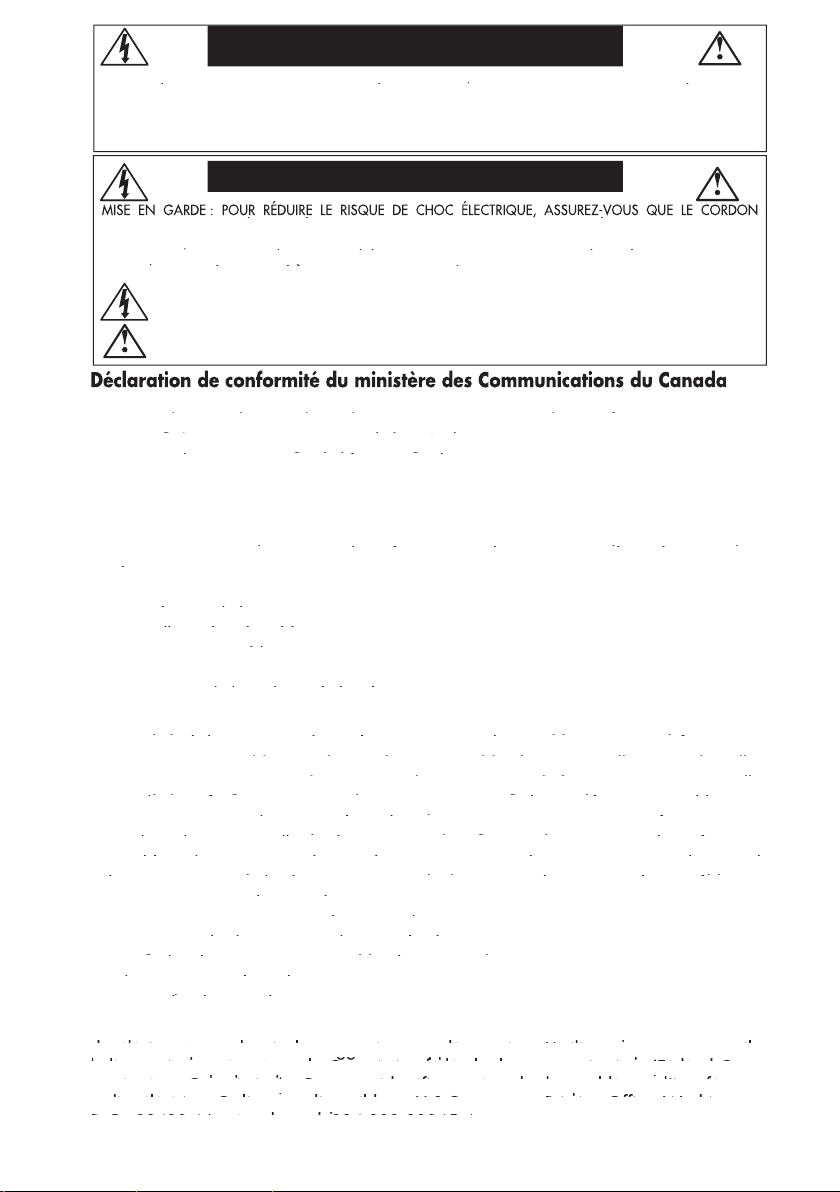
30-degree angle and lift up to the highest position. Connect all cables to
appropriate connectors (Figure 4).
management system that is built into the stand.
Place the D-Sub cable (not included)and the power cable into the
specifi c hooks as indicated. (Figure 5).
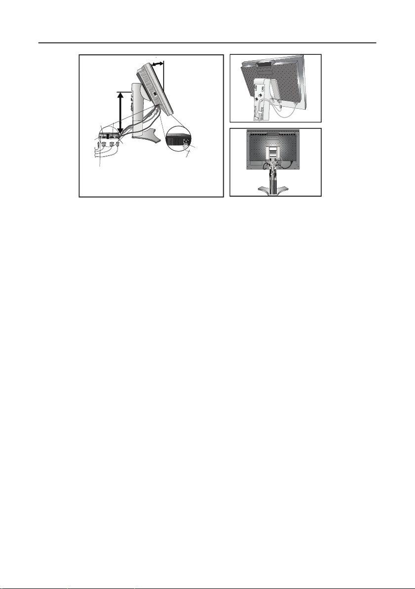
Place the DVI cable and the 15-pin mini D-Sub to DVI-A cable into the
hooks as indicated (Figure 6).
When using the monitor in Portrait mode, place the DVI cable and the 15-pin
mini D-Sub to DVI-A cable into the hooks as indicated (Figure 7).

4
Make sure to leave enough slack in the cables so that the Tilt and the
Raise and Lower functions of the monitor are not impeded.
stand (Figure 8).
Connect the power cord to power outlet.
NOTE: Please refer to the Recommended Use section of this manual for
proper selection of power cord.
ON position for the monitor to function (Figure 10).
Turn on the monitor using the front power button, then turn on the computer.
NOTE:
The Vacation Switch is a true on/off switch. If this
switch is in the OFF position, the monitor cannot be
turned on using the front button.
DO NOT turn the vacation switch ON/OFF repeatedly.
automatically adjusts the monitor to the optimal settings that are needed for
most signal timings.
For further adjustments, refer to the
section of this User’s Manual
for a full description of the OSM controls.
95/98/Me/2000/XP INF fi le for
your monitor, visit www.necdisplay.com/support.
Highest
Stand
Position
Power cord
DC-OUT
DVI-D
DVI-I
D-SUB
30 Tilt
the Soundbar attachment. Do not use this
connector unless specifi ed.)

5
–
Vacation

6
–
Portrait modes, refer to the “Controls” section of this user’s manual.
with your hands and adjust the swivel

7
(see Raising and Lowering Monitor Screen page 5).
Move the Quick Release Lever in the direction indicated by the arrows
(Figure S.2) .
The monitor can now be mounted using and alternate method.
Reverse the process to reattach stand.
–

8
Use ONLY the 4 screws that are included when mounting to avoid
The LCD monitor should only be used with an approved arm (e.g. GS

9
(On-Screen Manager) control buttons, located on the front
button.

10
Brightness/Contrast Controls
BRIGHTNESS: Adjusts the overall image and background screen brightness.
CONTRAST: Adjusts the image brightness in relation to the background.
AUTO CONTRAST (Analog input only): Adjusts the image displayed for
non-standard video inputs.
ECO MODE: Decreases the amount of power consumed by reducing the
brightness level.
1: Decreases the brightness by 25%.
2: Decreases the brightness by 50%.
CUSTOM: Decreases the brightness level as determined by
the user. Refer to the Advanced OSM menu for custom setting instructions.
AUTO BRIGHTNESS: There are three settings for Auto Brightness.
OFF: Auto Brightness does not function.
1: Adjusts the brightness automatically by detecting the brightness level of your
environment and adjusting the monitor accordingly with the best BRIGHTNESS
setting (see page 35 for AmbiBright™ explanation), making the viewing
experience more comfortable.
2: Adjusts the BRIGHTNESS level of the monitor to the best setting based on the
amount of white being displayed on the monitor. This function does not utilize
the AmbiBright sensor.
NOTE: Do not cover the AmbiBright sensor.
BLACK LEVEL: Adjust the black level.
Auto Adjust (Analog input only)
AUTO ADJUST:
Automatically adjusts the Image Position, H. Size, and Fine settings.

11
Image Controls
H.SIZE (V.SIZE) (Analog input only): Increases or decreases the horizontal
(or vertical) size.
If the “Auto Adjust function” does not provide a satisfactory picture,
further tuning can be performed manually using the “H. Size (or V. Size)”
function (dot clock).
To manually adjust the monitor, a Moiré test pattern should be used.
This function may alter the width of the picture. Use Left/Right Menu to center
the image on the screen.
If the H. Size (or V. Size) is set incorrectly, the screen would show vertical
banding, like the drawing on the left. The image should be clear.
If the “Auto Adjust” and the “H.Size” functions do not
provide a
tuning can be performed using the
tuning can be performed using the
“Fine” function. Adjusting
For Fine adjustment, a
incorrect, the screen would show horizontal banding like the drawing on the left.
The image should be clear.
AUTO FINE (Analog input only): Automatically adjusts the FINE settings.
When the AUTO FINE control is ON adjustment occurs approximately every 33
minutes or when a change in signal timing is detected.
EXPANSION: Selects the zoom mode.
FULL: The image is expanded to 1280 x 1024, regardless of the resolution.
ASPECT: The image is expanded without changing the aspect ratio.
OFF: The image is not expanded.
CUSTOM: Refer to the ADVANCED OSM Controls section of this user’s
manual for detailed instructions.
–
Adjustment
Adjustment
Adjustment
Adjustment

12
AccuColor
Control Systems
ACCUCOLOR
CONTROL SYSTEM: Seven preset color settings.
The sRGB and NATIVE, color presets are standard and cannot be changed.
The PROGRAMMABLE setting can only be adjusted using color calibration software
Tools
Tools
SHARPNESS:
resolution at any time. This setting can be set independently for different signal
timings (resolution settings).
you must restart the computer.
AUTO: When using the DVI-D to DVI-D cable, the DVI SELECTION is DIGITAL.
When using the D-SUB to DVI-A cable, the DVI SELECTION is ANALOG.
DIGITAL: DVI digital input is available.
ANALOG: DVI analog input is available.
DVI Input mode on the monitor must be set to DIGITAL in the DVI SELECTION
menu. To set the DVI SELECTION to “DIGITAL” press the SELECT button then
CONTROL button when the DVI signal cable is connected to the DVI-I connector
of the monitor. Otherwise the MAC may not turn on.
NOTE: Depending on the type of PC/Video card or the type of video signal
cable used, the DVI SELECTION function may not operate.
VIDEO DETECT: Selects the method of video detection when more than one video
input source is connected to the monitor.
FIRST: If “FIRST” is selected as the VIDEO DETECT option, the
monitor displays the signal from the fi rst input port. If there is no signal present
at the fi rst input port, then the monitor will search for a signal from the next
input port.
If a new input signal is connected to another of the monitor’s input ports while
the monitor is in FIRST mode, the monitor DOES NOT automatically
SWITCH to the new source.

13
LAST: If “LAST” is selected as the VIDEO DETECT option, then
each time a new input source is detected, the monitor will automatically display
the new signal.
NONE: The monitor will only search other input ports while the power is on.
of time passes. Before powering off, a message will appear on the screen asking
the user if they want to delay the turn off time by 60 minutes. Press any OSM
button to delay the turn off time.
IPM: T
mode after a period of inactivity. The IPM has three settings.
OFF: Monitor does not go into power save mode when the input signal is lost.
STANDARD:
signal is lost.
OPTION: Monitor enters power save mode automatically when the amount of
surrounding light goes below the level that is determined by the user. This level
can be determined in Tag 7 of the Advanced OSM Control menu.
When in power save mode, the LED on the front of the monitor blinks amber.
While in power save mode, push any of the front buttons, except for POWER and
SELECT to return to normal operation.
When the amount of surrounding light returns to normal levels, the monitor will
automatically return to normal mode.
COLORCOMP:
the white uniformity level, as well as for slight differences in color that may occur throughout
the display area of the screen. These variations are characteristic of LCD panel
technology. This function improves the color and evens out the luminance uniformity
of the display.
NOTE: Using the COLORCOMP feature reduces the overall peak luminance of
the display. If greater luminance is desired over the uniform performance of the
display, then COLORCOMP should be turned off.
MENU Tools
OSM control menus are available in eight languages.
OSM LEFT/RIGHT: You can choose the location where the OSM appears on
your screen. The LEFT/RIGHT submenu moves the OSM horizontally.
OSM DOWN/UP: You can choose the location where the OSM appears on your
screen. This DOWN/UP submenu moves the OSM vertically.

14
–
OSM LOCK OUT
OSM control functions. When attempting to activate OSM controls while in the Lock
Out mode, a screen will appear indicating the OSM controls are locked out.
There are four ways to use OSM LOCK OUT function:
1. OSM LOCK OUT with BRIGHTNESS and CONTRAST control: This mode
locks all OSM functions except for BRIGHTNESS and CONTRAST.
To activate, press the SELECT and “Up” buttons simultaneously, while in the
OSM menu.
To deactivate, press the SELECT and “Up” buttons simultaneously, while in
the OSM menu
2. OSM LOCK OUT with no control: This mode prevents access to all
OSM functions.
To activate, press the SELECT and “Right” buttons simultaneously.
To deactivate, press the SELECT and “Right” buttons simultaneously,
while in the OSM menu.
3. OSM LOCK OUT with BRIGHTNESS (only) control: This mode locks all OSM
functions except for BRIGHTNESS.
To activate, press the SELECT, “Left” and "Down" buttons simultaneously,
while in the OSM menu.
To deactivate, press SELECT, then “Left” and "Down" buttons simultaneously
while in the OSM menu.
4. CUSTOM: refer to the Advanced OSM Menu.
OSM TRANSPARENCY: Adjusts the transparency of the OSM Menu.
OSM COLOR: “Tag window frame color”, “Item select color” and “Adjust window
frame color” can be changed to Red, Green, Blue, or Gray.
RESOLUTION NOTIFIER: The Resolution Notifi er warns the user if the input signal
to the monitor is set at something other than the optimized resolution of
1280 x 1024. If the monitor detects a signal that is not at the optimized
resolution then, after 30 seconds, a warning message will appear on the screen.
When the Resolution Notifi er is ON, the warning will appear every 30 seconds.
The Resolution Notifi er can be turned OFF in the OSM. The factory default for the
Resolution Notifi er is ON.

15
HOT KEY: When this function is activated, the brightness and contrast of the
monitor can be adjusted without entering the OSM menu.
The “Left” or “Right” buttons adjust the brightness level.
The “Down” or Up” buttons adjust the contrast level.
FACTORY PRESET: Selecting the factory preset allows the user to reset most of the
OSM control settings back to the factory settings.
Individual settings can be reset by highlighting the control that needs to be reset,
and pressing the RESET button.
Information
Also provides technical information including which preset timing is being used as
well as the horizontal and vertical frequencies.
with the input signal. These warnings will disappear when the Exit button is pressed.
After power is turned on or when there is a change of input signal, the No Signal
window will appear.

16
for at least one second. Then press one of the following front OSM buttons: EXIT,
LEFT, RIGHT, UP, or DOWN.
standard OSM and has numbered tags instead of icons.
Adjusts the overall image and background screen brightness.
Adjusts the image brightness and contrast in relation to the
AUTO BRIGHTNESS has three settings.
Adjusts the black level.

17
Automatically adjusts the Image Position, H. Size, and
resolutions less than 800 x 600 resolution.

18
Time
Long Cable Software. To download the software, please visit www.necdisplay.com.

19

20
1: This setting is recommended for Video input sources.
Dark areas will look brighter and high bright areas will
look darker.
2: Curve based on the DICOM GSDF, for use with grayscale
images.
Custom Value: Selectable Gamma ranging from 0.5 to 4.0
in 0.1 increments. Not adjustable in sRGB color preset.
OFFSET: Digitally adjusts the black level after the signal is
converted from analog to digital.
CONTROL SYSTEM: Seven preset color settings.

21
video input is connected.

22
control: This mode locks all OSM functions except for
BRIGHTNESS and CONTRAST.
To activate, press the SELECT and “Up” buttons
simultaneously, while in the OSM menu.
To deactivate, press the SELECT and “Up” buttons
simultaneously, while in the OSM menu.
to all OSM functions. To activate, press the SELECT and
“Right” buttons simultaneously. To deactivate, press the
SELECT and “Right” buttons simultaneously, while in the OSM
menu.
mode locks all OSM functions except for BRIGHTNESS.
To activate, press the SELECT, “Left” and “Down” buttons
simultaneously, while in the OSM menu.
To deactivate, press SELECT, “Left” and “Down” buttons
simultaneously, while in the OSM menu.
Menu. Select ENABLE or DISABLE for: POWER KEY, INPUT
SEL, HOT KEY (BRIGHTNESS/CONTRAST), ECO MODE,
WARNING (RESOLUTION NOTIFIER/OSM LOCK OUT).
To Deactivate the OSM Lock Out function, press RESET and
EXIT to bring up the LOCK OUT warning. Press SELECT,
SELECT, <, >, <, >, EXIT.

23

24
video noise from a poor signal. Press “Left” or “Right” to select.

25
TileComp using 4 monitors (black area shows monitor frames).
TileComp OFF

26

27
level that the monitor will go up to when the
ambient light level is highest. Make sure the
room is at its brightest when setting this level.
Select “1” in the AUTO BRIGHTNESS menu
(Figure 1).
Then use the front buttons to move the cursor
up to the BRIGHTNESS setting. Choose the
desired brightness level(Figure 2).
brightness that the monitor will go down to
when the ambient light level is low. Make
sure the room is at its darkest when setting
this level.
Then use the front buttons to move the cursor
up to the BRIGHTNESS setting. Choose the
desired brightness level(Figure 3).

28
lighting level of room
Bright Ambient
Lighting Conditions
Dim Ambient
Lighting Conditions
Screen Brightness value using the Auto Brightness function
continued

29
simultaneously.
menu: EXIT, LEFT, RIGHT, UP, or DOWN.
controls and software utilities, visit our
website at www.necdisplay.com.
SIMPLE X
FULL X
DETAIL
"Size" "Fine"
"Position"
O
O
O
X
O
O O
1 seconds
1.5 seconds
5 seconds
Time
"
Contrast"
Long cable capability *1
Black Level,
X: Automatic adjustment is not performed.
To download the software, please visit www.necdisplay.com.

30
LCD COLOR MONITOR:
which can be harmful or fatal or may cause electric shock, fi re or equipment failure.
with this monitor. If a power cord is not supplied with this monitor, please contact your supplier.
• If the monitor has been dropped or the cabinet damaged.
• If the monitor does not operate normally by following operating instructions.
• Allow adequate ventilation around the monitor so that heat can properly dissipate.
Do not block ventilated openings or place the monitor near a radiator or other heat sources.
Do not put anything on top of monitor.
• The power cable connector is the primary means of detaching the system from the
supply. The monitor should be installed close to a power outlet which is easily accessible.
• Handle with care when transporting. Save packaging for transporting.

31
warm-up.
–

32
with benzene, thinner, alkaline detergent, alcoholic system detergent,
glass cleaner, wax, polish cleaner, soap powder, or insecticide. Do not
place rubber or vinyl against the cabinet for long periods. These types
of fl uids and fabrics can cause the paint to deteriorate, crack, or peel.
–

33
Viewable Image Size: 19,0 inch liquid crystal display(LCD); 0.294 mm dot
Native Resolution (Pixel Count): 1280x1024 pitch; 250cd/m
white luminance; XtraView+™
technology; 800:1 contrast ratio, typical
Sync: Separate sync. TTL Level Positive/Negative
Composite sync. Positive/Negative
Sync on Green (Video 0.7Vp-p and Sync Negative 0.3V p-p)
Viewing Angle Left/Right: ± 89˚ (CR>10)
Up/Down: ± 89˚ (CR>10)
640 x 480*1 at 60 Hz to 85 Hz all modes listed.
800 x 600*1 at 56 Hz to 85 Hz
832 x 624*1 at 75 Hz
1024 x 768*1 at 60 Hz to 85 Hz
1152 x 864*1 at 70 Hz to 85 Hz
1152 x 870*1 at 75 Hz NEC DISPLAY SOLUTIONS cites
1280 x 960 *1 at 60 Hz recommended resolution at 60Hz for optimal
1280 x 1024 at 60 Hz to 75 Hz.................. display performance.
1024 x 1280 *1 at 60 Hz
Active Display Area Landscape : Horiz. : 376 mm/14.8 inches
Vert. : 301 mm/11.9 inches
Portrait : Horiz. : 301 mm/11.9 inches
Vert. : 376 mm/14.8 inches
15.8 inches (W) x 14.4 - 19.5 inches (H) x 9.7 inches (D)
Portrait: 330.3 mm (W) x 446.7 - 596.7 mm (H) x 247.3 mm (D)
13.0 inches (W) x 16.9 - 21.0 inches (H) x 9.7 inches (D)
Height Adjustment: 150 mm / 5.9 inches (Landscape)
Weight 8.4 kg
18.5 lbs
Operating Temperature: 5°C to 35°C/41°F to 95°F
Humidity: 30% to 80%
Altitude: 0 to 10,000 Feet
Storage Temperature: -10°C to 60°C/14°F to 140°F
Humidity: 10% to 85%
Altitude: 0 to 40,000 Feet

34
Ambix3™ Technology:
technology compatibility for analog as well as DVI-based
The integrated interface ratifi ed by the Digital Display Working Group (DDWG) that
The digital-only subset of DVI ratifi ed by the Digital Display Working Group (DDWG)
An all-digital interface for fl at panel monitors which is signal
Allows users to adjust the monitor to the orientation that best fi ts their
weight allow it to be moved or transported easily from one location to another.
AccuColor
Control System:
Allows the user to adjust the colors on the screen and
(On-Screen Manager) Controls:
Allow you to quickly and easily adjust all
Features:
The Microsoft
solution with the Windows
directly to your computer, automatically optimizing

35
(Intelligent Power Manager) System:
Provides innovative power-saving
Automatically adjusts monitor to the display card’s
Capability: Allows you to use the entire screen area in most resolutions,
XtraView+™ Wide Viewing Angle Technology:
Allows the user to be able to see
VESA Standard Mounting Interface:
Allows users to connect their MultiSync monitor
Allows you to view more of your ideas and less of the monitor bezel,
while freeing up more horizontal and vertical desktop space for multiple-monitor applications.
you to more easily adjust OSM display settings via mouse and keyboard.
Automatic long cable compensation prevents image quality degradation
Advanced No Touch Auto Adjust™:
Provides optimal image settings upon initial
Delivers virtually uninterrupted, undistorted viewing of full-motion
video applications.
A new optimized color management standard which allows for
with other common color standards.
This feature compensates for slight variations in the white uniformity level
Adjustable stand with pivot capability:
Adds flexibility to your viewing
AmbiBright™ technology:
Automatically adjusts the backlight level depending on the

36
• The display card should be completely seated in its slot.
• Check the Vacation Switch should be in the ON position.
• Front Power Switch and computer power switch should be in the ON position.
• Check to make sure that a supported mode has been selected on the display card
or system being used. (Consult display card or system manual to change graphics
mode.)
• Check the monitor and your display card with respect to compatibility and
recommended settings.
• Check the signal cable connector for bent or pushed-in pins.
• Check the signal input, “DVI-D”, “DVI-I”, or “D-Sub”.
• Ensure the DVI input mode is set to DIGITAL when the MAC digital output is
connected to the DVI-I connector.
• If the front LED is blinking amber, check the status of the IPM mode (see page 13).
• Unplug the power cord of the monitor from the AC outlet to turn off and reset the
monitor.
• Check the Vacation Switch on the left side of the monitor.
RANGE” is displayed: Either signal clock or resolution is too high. Choose one of
the supported modes.
• OSM warning “OUT OF RANGE” is displayed on a blank screen:
Signal frequency is out of range. Choose one of the supported modes.

37
• Signal cable should be completely attached to the computer.
• Use the OSM Image Adjust controls to focus and adjust display by increasing or
decreasing the fi ne total. When the display mode is changed, the OSM Image
Adjust settings may need to be readjusted.
• Check the monitor and your display card with respect to compatibility and
recommended signal timings.
• If your text is garbled, change the video mode to non-interlace and use 60Hz
refresh rate.
•
•
turned off.
•
turned off.
•
•
card or
system being used. (Consult display card or system manual to change
graphics mode.)
•
If no video is present on the screen, turn the Power button off and on again.
•
mouse).
•
the LCD detects a problem, the LED on the front fl ashes in a pattern of long and
short blinks, depending on the type of problem detected.
If the LED detects a problem, please refer service to qualifi ed personnel.

38
Fax: (800
Warranty Information: www.necdisplay.com
World Wide Web: www.necdisplay.com

39
WARRANTIES ARE IN LIEU OF ALL OTHER WARRANTIES EXPRESS OR IMPLIED, INCLUDING,
A PARTICULAR PURPOSE. SOME STATES DO NOT ALLOW THE EXCLUSION OF IMPLIED
WARRANTIES OR THE LIMITATION OR EXCLUSION OF LIABILITY FOR INCIDENTAL OR
APPLY TO YOU.

40
– chlorinated and brominated fl ame retardants and polymers
– heavy metals such as cadmium, mercury and lead.
www.tcodevelopment.com

41
Japan: http://www.nec-display.com
Japan - http://www.diarcs.com/
Approx.
42W Green or

We hereby certify that the color monitor
LCD1990SXp (L195RR)
– EN 60950-1
– EN 55022
– EN 61000-3-2
– EN 61000-3-3
– EN 55024
Within the European Union
EU-wide legislation, as implemented in each Member State, requires that waste
electrical and electronic products carrying the mark (left) must be disposed of
separately from normal household waste. This includes monitors and electrical
accessories, such as signal cables or power cords. When you need to dispose of
your NEC display products, please follow the guidance of your local authority,
or ask the shop where you purchased the product, or if applicable, follow
any agreements made between yourself and NEC. The mark on electrical and
electronic products only applies to the current European Union Member States.
Outside the European Union
If you wish to dispose of used electrical and electronic products outside the European Union, please
contact your local authority so as to comply with the correct disposal method.
43
VERCLE (NI LE PANNEAU ARRIÈRE). AUCUN ÉLÉMENT UTILISABLE PAR L’UTILISATEUR À L’INTÉRIEUR. TOUT TRAVAIL
Ce symbole avertit l’utilisateur qu’une haute tension non isolée dans l’appareil peut avoir une amplitude suffi sante
pour provoquer un choc électrique. Tout contact avec une de ces parties pose un risque d’électrocution.
Ce symbole avertit l’utilisateur qu’une documentation importante concernant le fonctionnement et l’entretien
de cet appareil est incluse. Cela est essentiel pour assurer sa protection et celle de l’appareil.
AVERTISSEMENT
ATTENTION
règlements du Canada sur l’équipement provoquant des interférences (Canadian
Interference-Causing Equipment Regulations).
règlements du Canada sur l’équipement provoquant des interférences (Canadian
règlements du Canada sur l’équipement provoquant des interférences (Canadian
Regulations) selon CAN/CSA C22.2 N° 60950-1.
(L195RR)pour ne pas provoquer d’interférences avec les réceptions radio et du
téléviseur.
(L195RR)pour ne pas provoquer d’interférences avec les réceptions radio et du
(L195RR)pour ne pas provoquer d’interférences avec les réceptions radio et du
(1)Utiliser le câble d’alimentation fourni ou l’équivalent pour assurer la conformité au
Règlement de la FCC.
(1)Utiliser le câble d’alimentation fourni ou l’équivalent pour assurer la conformité au
(1)Utiliser le câble d’alimentation fourni ou l’équivalent pour assurer la conformité au
(2)Veuillez utiliser le câble signal vidéo armé, mini D-SUB à 15 broches au câble DVI-A,
Règlement de la FCC.
Règlement de la FCC.
ou DVI-D au câble DVI-D.
(2)Veuillez utiliser le câble signal vidéo armé, mini D-SUB à 15 broches au câble DVI-A,
(2)Veuillez utiliser le câble signal vidéo armé, mini D-SUB à 15 broches au câble DVI-A,
L’utilisation d’autres câbles et adaptateurs peut provoquer une interférence avec la
réception de la radio et de la télévision.
L’utilisation d’autres câbles et adaptateurs peut provoquer une interférence avec la
L’utilisation d’autres câbles et adaptateurs peut provoquer une interférence avec la
B en vertu de la section 15 des règlements FCC. Ces limites sont prévues pour fournir une
protection raisonnable contre les interférences nuisibles dans une installation résidentielle.
B en vertu de la section 15 des règlements FCC. Ces limites sont prévues pour fournir une
B en vertu de la section 15 des règlements FCC. Ces limites sont prévues pour fournir une
Cet équipement génère, utilise et peut radier une énergie de fréquence, et si non installé
protection raisonnable contre les interférences nuisibles dans une installation résidentielle.
protection raisonnable contre les interférences nuisibles dans une installation résidentielle.
et utilisé conformément aux instructions, peut causer des interférences nuisibles aux
Cet équipement génère, utilise et peut radier une énergie de fréquence, et si non installé
Cet équipement génère, utilise et peut radier une énergie de fréquence, et si non installé
communications radio. Cependant, il n’est pas garanti qu’aucune interférence ne se
et utilisé conformément aux instructions, peut causer des interférences nuisibles aux
et utilisé conformément aux instructions, peut causer des interférences nuisibles aux
produira dans une installation donnée. Si cet équipement ne provoque pas d’interférences
communications radio. Cependant, il n’est pas garanti qu’aucune interférence ne se
communications radio. Cependant, il n’est pas garanti qu’aucune interférence ne se
nuisibles à la réception radio ou télé, ce qui peut être déterminé en mettant l’appareil
produira dans une installation donnée. Si cet équipement ne provoque pas d’interférences
produira dans une installation donnée. Si cet équipement ne provoque pas d’interférences
hors et sous tension, l’utilisateur est encouragé à essayer de supprimer les interférences
nuisibles à la réception radio ou télé, ce qui peut être déterminé en mettant l’appareil
nuisibles à la réception radio ou télé, ce qui peut être déterminé en mettant l’appareil
en suivant une ou plusieurs des instructions suivantes :
hors et sous tension, l’utilisateur est encouragé à essayer de supprimer les interférences
hors et sous tension, l’utilisateur est encouragé à essayer de supprimer les interférences
• réorienter ou repositionner l’antenne de réception;
en suivant une ou plusieurs des instructions suivantes :
en suivant une ou plusieurs des instructions suivantes :
• augmenter la distance entre l’appareil et le récepteur;
• réorienter ou repositionner l’antenne de réception;
• réorienter ou repositionner l’antenne de réception;
• Branchez l’équipement à une prise de courant sur un circuit différent de celui auquel
• augmenter la distance entre l’appareil et le récepteur;
• augmenter la distance entre l’appareil et le récepteur;
le récepteur est branché.
• Branchez l’équipement à une prise de courant sur un circuit différent de celui auquel
• Branchez l’équipement à une prise de courant sur un circuit différent de celui auquel
• Consultez le revendeur ou un technicien radio-télé qualifi é pour obtenir de l’aide.
le récepteur est branché.
le récepteur est branché.
AFIN D’ÉVITER TOUT RISQUE D’INCENDIE ET D’ÉLECTROCUTION, NE PAS EXPOSER CET APPAREIL À LA PLUIE OU À

44
Votre nouvelle boîte* de moniteur NEC MultiSync ACL doit
avec une base inclinable et pivotante à hauteur

45
câble de signal DVI au connecteur de la carte d’affi chage de votre système
(Figure A.1). Serrer toutes les vis.
Pour un PC à sortie analogique : Connectez le mini D-SUB à 15 broches au
câble du signal DVI-A au connecteur de la carte d’affi chage de votre système
(Figure A.2).
Pour un MAC : Connectez l’adaptateur de câble Macintosh MultiSync à
l’ordinateur, puis connecter le câble mini D-SUB à 15 broches à l’adaptateur
du câble Macintosh MultiSync (Figure B.1).
câble Macintosh :
joindre NEC Display Solutions of America, Inc., au (800) 6324662.
l’arrière de 30° en le soulevant dans sa position la plus haute. Connectez tous
les câbles aux connecteurs appropriés (Figure 4).
rangement de câbles qui est intégré dans la base.
Placez le câble D-Sub (non fourni) et le cordon d’alimentation dans les crochets
spécifi ques indiqués. (Figure 5).
Placez le câble DVI et le câble mini D-Sub à 15 broches à DVI-A dans les
crochets spécifi ques indiqués (Figure 6).
Si vous utilisez le moniteur en mode Portrait, placez le câble DVI et le câble
Mini D-Sub à 15 broches à DVI dans les crochets spécifi ques indiqués
(Figure 7).
Adaptateur Macintosh

46
Assurez vous de laisser assez de distance dans les câbles pour que
l’inclinaison et les fonctions de relèvement et de descente du moniteur ne
soient pas entravées.
support (Figure 8).
Branchez le cordon d’alimentation dans la prise murale.
REMARQUE : Veuillez consulter la section Utilisation recommandée de ce
manuel pour sélectionner le cordon d’alimentation approprié.
tension pour que le moniteur fonctionne (Figure 10).
Mettez le moniteur et l’ordinateur sous tension en utilisant la touche de mise en
marche frontale.
REMARQUE :
mise sous/hors tension. Si ce Bouton est en position
arrêt, le moniteur ne peut pas se mettre sous tension
en utilisant la touche frontale.
NE PAS MODIFIER la position de ce commutateur de veille de
façon répétée.
sans intervention automatique ajuste le moniteur sur les réglages optimaux
nécessaires pour la plupart des synchronisations de signaux.
Pour des ajustements plus approfondis, consulter la section Commandes de ce
manuel d’utilisation.
Pour une description complète des commandes OSM.
Pour télécharger un fi chier d’information sur Windows® 95/98/Me/2000/XP
INF pour votre moniteur, visitez www.necdisplay.com/support.
REMARQUE : Si vous rencontrez des problèmes, veuillez consulter la section
Dépannage de ce manuel de l’utilisateur.
Position
du support
la plus élevée
Cordon d’alimentation
DC-OUT
DVI-D
DVI-I
D-SUB
30 Tilt
–

47
–
Veille
Alimentation
de mise sous/hors tension. Si ce Bouton est en
position arrêt, le moniteur ne peut pas se mettre
sous tension en utilisant le bouton frontal.

48
Avant la rotation, l’écran doit être relevé au niveau le plus haut pour éviter les
Attrapez l’écran du moniteur des
Attrapez l’écran du moniteur des deux cô-

49
(voir Élévation et descente de l’écran du moniteur page 47).
Déplacez le levier de dégagement rapide dans le sens indiqué par les fl èches.
(Figure S.2).
Le moniteur peut maintenant être remonté en inversant le la méthode.
Inversez le processus pour remettre le socle en place.
REMARQUE : Utilisez uniquement une méthode de montage VESA compatible.
(Espacement de 100mm)
REMARQUE : Prenez des précautions pour ôter le support du moniteur.
–

50
–
MISE EN GARDE :
Utilisez uniquement les 4 vis qui sont incluses pour le montage
afi n d’éviter d’endommager le moniteur, le support ou le bras. Les
exigences sur la sécurité requièrent que le moniteur soit monté sur
un bras garantissant la stabilité de l’appareil et capable de
soutenir son poids. Le moniteur ACL ne doit être utilisé qu’avec
un bras approuvé (portant la marque GS).

51
ALIMENTATION
(ENTRÉE/SÉLECTION)
Accède au menu de commande OSM. Entre dans les sous-
(GAUCHE/DROITE)
(HAUT/BAS)
(RÉINITIALISER/
ROTATION du OSM)

52
Commandes de luminosité/contraste
LUMINOSITÉ : Ajuste la luminosité globale de l’image et du fond.
CONTRASTE : Ajuste la luminosité de l’image par rapport au fond.
CONTRASTE AUTO. (Entrée analogique seulement) : Ajuste l’image affi chée pour
les entrées vidéo non standard.
MODE ÉCO : Diminue le niveau d’énergie consommée en réduisant le
niveau de luminosité.
1: Diminue la luminosité de 25 %.
2: Diminue la luminosité de 50 %.
PERSO. : Diminue le niveau de
luminosité selon le choix de l’utilisateur. Consultez le menu OSM option-
avancée pour les instructions de réglage personnalisé.
LUMINOSITÉ AUTO. : Il existe trois réglages de luminosité automatique.
ARRÉT : La luminosité automatique ne fonctionne pas.
de votre environnement et ajuste le moniteur selon le meilleur réglage
de LUMINOSITÉ (voir page 77 pour les explications du Ambibright),
de votre environnement et ajuste le moniteur selon le meilleur réglage
de votre environnement et ajuste le moniteur selon le meilleur réglage
donnant une vision plus confortable.
NIVEAU DE NOIR : Règle le niveau de noir.
Réglage auto (Entrée analogique seulement)
AUTO : Ajuste automatiquement la position de l’image et
les paramètres de la taille H et les paramètres de précision.

53
Commandes d’image
AUCHE/DROITE
: Contrôle la position horizontale de l’image dans la zone
d’affi chage de l’ACL.
BAS/HAUT : Contrôle la position verticale de l’image dans la zone
d’affi chage de l’ACL.
HAUTEUR (LARGEUR) (Entrée analogique seulement) : Augmente ou diminue la
taille verticale ou horizontale.
Si la « Réglage Auto » ne fournit pas un résultat satisfaisant,
il est possible de procéder à un réglage plus fi n avec la commande « HAUTEUR
(ou LARGEUR )» (phase d’horloge).
Pour ajuster manuellement le moniteur, vous devrez utiliser un motif de test Moiré.
Cette fonction peut altérer la largeur de l’image. Utilisez le menu gauche/droite
pour centrer l’image dans l’écran.
Si HAUTEUR (LARGEUR) est réglée de façon incorrecte, l’écran montera une
bande verticale, comme sur le schéma de gauche.. L’image doit être impeccable.
FINESSE (Entrée analogique seulement) : Si les fonctions « Réglage Auto »
et « Hauteur » ne fournissent pas une image satisfaisante, il est possible d’effectuer
manuellement un réglage de précision à l’aide de la fonction « Finesse ».
L’ajustement de ce réglage améliore la mise au point, la netteté et la stabilité de
l’image.
Pour ce faire, vous devrez utiliser un motif de test Moiré. Si le réglage de Finesse
n’est pas correctement étalonné, vous obtiendrez le résultat illustré sur le dessin de
gauche. L’image doit être impeccable.
(Entrée analogique seulement) : Ajuste automatiquement les
réglages de précision.
Quand le contrôle de Finesse Auto. est marche, l’ajustement intervient
toutes les 33 minutes ou quand un changement de synchronisation de signal est
détecté.
EXPANSION : Sélectionne le mode zoom.
PLEIN : L’image est agrandie à 1280 x 1024, quelle que soit sa défi nition.
ASPECT : L’image est agrandie sans que le facteur d’aspect soit modifi é.
ARRÊT : L’image n’est pas agrandie.
ASPECT : L’image est agrandie sans que le facteur d’aspect soit modifi é.
ASPECT : L’image est agrandie sans que le facteur d’aspect soit modifi é.
PERSO. : Consultez la section des commandes OSM option-avancée du
manuel d’utilisation pour plus d’informations.
–
Ajustement
Ajustement
Ajustement
Ajustement

54
–
Systèmes de commande AccuColor
: Sept réglages de couleurs préréglées.
Les réglages préprogrammés sRGB et NATIVE sont standards et ne peuvent pas être
modifi és.
Les réglages PROGRAMMABLE peuvent seulement être ajustés en utilisant le
logiciel de calibration des couleurs tel que GammaComp ou Spectraview II de NEC.
Outils
NETTETÉ : Cette fonction utilise la technologie numérique pour conserver une
image contrastée à tout moment. Ce réglage peut être réglé indépendamment pour
les différentes synchronisations de signal (réglage de résolution).
sélection DVI est changée, vous devez redémarrer votre ordinateur.
AUTO : Avec le câble DVI-D au DVI-D, la SÉLECTION DVI est NUMÉRIQUE.
Avec le câble D-SUB à DVI-A, la SÉLECTION DVI est ANALOGIQUE.
NUMÉRIQUE : L’entrée DVI numérique est disponible.
ANALOGIQUE : L’entrée DVI analogique est disponible.
REMARQUE : Quand vous utilisez un MAC avec une sortie numérique : Avant de
mettre sous tension le MAC, le mode d’entrée DVI du moniteur doit être réglé sur
NUMÉRIQUE dans la sélection DVI OSM. Pour régler la SÉLECTION DVI sur
mettre sous tension le MAC, le mode d’entrée DVI du moniteur doit être réglé sur
mettre sous tension le MAC, le mode d’entrée DVI du moniteur doit être réglé sur
NUMÉRIQUE, appuyez sur la touche de SÉLECTION puis sur la touche
NUMÉRIQUE dans la sélection DVI OSM. Pour régler la SÉLECTION DVI sur
NUMÉRIQUE dans la sélection DVI OSM. Pour régler la SÉLECTION DVI sur
COMMANDE quand le signal DVI est connecté au connecteur DVI-I du moniteur.
Sinon, il est possible que le MAC ne puisse être mis sous tension.
REMARQUE : Selon le type de carte PC/vidéo ou le type de câble de signal
vidéo utilisé, la commande de SÉLECTION DVI peut ne pas fonctionner
REMARQUE : Selon le type de carte PC/vidéo ou le type de câble de signal
REMARQUE : Selon le type de carte PC/vidéo ou le type de câble de signal
source d’entrée vidéo est connectée au moniteur.
PREM. : Si la première détection est sélectionnée comme
option de détection vidéo, le moniteur affi che le signal du premier port d’entrée.
Lorsque le signal d’entrée vidéo actuel est absent du premier port d’entrée, le
moniteur cherche un signal vidéo sur le port d’entrée suivant.
Si un nouveau signal est connecté sur un des autres port d’entrée du moniteur
quand le moniteur est en mode de première détection, le moniteur n’IRA pas
automatiquement sur la nouvelle source vidéo.

55
DERN. : Si la dernière détection est sélectionnée comme option
de détection vidéo, le moniteur affi che automatiquement le nouveau signal à
chaque fois qu’une nouvelle source d’entrée est détectée.
AUCUN : Le moniteur cherchera seulement les autres ports d’entrée quand
l’alimentation est allumée.
ARRÊT PROGRAMMATEUR : Le moniteur s’éteint automatiquement après la
période d’inactivité programmée par l’utilisateur. Avant de mettre, un message
semblera sur l’écran demandant à l’utilisateur s’ils hors tension veulent retarder
le tour outre du temps par 60 minutes. Appuyez sur n’importe quel bouton d’OSM
pour retarder le tour outre du temps.
économique après une période inactivité. L’IMP possède trois réglages.
ARRÉT
: Le moniteur ne passe pas en mode économique quand le signal
est perdu.
STANDARD : Le moniteur passe en mode économique automatiquement quand
le signal est perdu.
OPTION : Le moniteur passe en mode économique automatiquement quand la
quantité de lumière ambiante passe sous le seuil déterminé par l’utilisateur. Le
niveau peut être déterminé sur le tag 7 du menu de commandes OSM-Option
avancée
En mode économique, le DEL sur l’avant du moniteur clignote en orangé.
En mode économique, appuyez sur une des touches frontales, exceptées les
touches TENSION et SÉLECTION, pour retourner en mode normale de
En mode économique, appuyez sur une des touches frontales, exceptées les
En mode économique, appuyez sur une des touches frontales, exceptées les
fonctionnement.
Quand la quantité de lumière ambiante retourne à un niveau normal, le moniteur
retournera automatiquement en mode normal.
niveau d’uniformité du blanc ainsi que les déviations de couleurs qui peuvent apparaître
dans la zone d’affi chage de l’écran. Ces variations sont caractéristiques à la technolo
gie d’écran ACL Cette commande améliore la couleur et égalise l’uniformité de
luminance de l’affi chage.
REMARQUE : L’utilisation du dispositif COMP COULEUR diminue la crête de luminance
générale de l’affi chage. Si une luminance supérieure est désirée après les performances
d’uniformité, le COMP COULEUR doit être éteint.

56
Menu Outils
OSM GAUCHE/DROITE : Il est possible de choisir la position d’affi chage du menu
OSM à l’écran. Le sous-menu GAUCHE/DROITE déplace l’OSM horizontalement.
OSM BAS / HAUT : Il est possible de choisir la position d’affi chage du
menu OSM à l’écran. Le sous-menu en BAS / HAUT déplace l’OSM verticalement.
EXTINCTION DE L’OSM : Le menu des commandes OSM demeure à l’écran
aussi longtemps qu’il est utilisé. Vous pouvez sélectionner la durée pendant
laquelle le moniteur attend après la dernière pression d’une touche pour fermer
le menu de commandes OSM. Cette période peut être programmée de 10 à 120
secondes, par intervalles de 5 secondes.
VERROUILLAGE OSM : Cette commande verrouille complètement l’accès de
certaines ou de toutes les commandes OSM. Toute tentative d’activation d’une
commande OSM en mode verrouillage OSM entraîne l’affi chage d’un écran
indiquant que l’accès à ces commandes est interdit.
Il existe 4 façons d’utiliser la commande de VERROUILLAGE OSM :
Ce mode verrouille tous les contrôles d’OSM, exceptées pour la
LUMINOSITÉ et le CONTRASTE.
Ce mode verrouille tous les contrôles d’OSM, exceptées pour la
Ce mode verrouille tous les contrôles d’OSM, exceptées pour la
Pour activer, appuyez simultanément sur les touches SÉLECTION et EN
HAUT, dans le menu OSM.
Pour désactiver, appuyez simultanément sur les touches SÉLECTION et EN
HAUT, dans le menu OSM.
commandes OSM.
Pour activer, appuyez simultanément sur les touches SÉLECTION et
DROITE.
Pour désactiver, appuyez simultanément sur les touches SÉLECTION et EN
DROITE, dans le menu OSM.
Ce mode verrouille toutes les commandes d’OSM exceptées pour la
LUMINOSITÉ.
Ce mode verrouille toutes les commandes d’OSM exceptées pour la
Ce mode verrouille toutes les commandes d’OSM exceptées pour la
Pour activer, appuyez simultanément sur les touches SÉLECTION et
GAUCHE, et BAS dans le menu OSM.
Pour désactiver, appuyez simultanément sur les touches SÉLECTION et
GAUCHE et BAS, dans le menu OSM.
OSM : Ajuste la transparence du menu OSM.

57
Information
AVERTISSEMENT OSM : Les menus d’avertissement OSM mettent en garde
Pour en savoir plus sur les éléments du menu utilisateur avancé voir
« Commandes OSM-Option avancée ».

58
« MARCHE » et « SÉLECTION » pendant au moins une seconde. Appuyez ensuite
sur la touche frontale OSM : EXIT,
« MARCHE » et « SÉLECTION » pendant au moins une seconde. Appuyez ensuite
« MARCHE » et « SÉLECTION » pendant au moins une seconde. Appuyez ensuite
que l’OSM standard et possède des Tags numérotés à la place des icônes.
votre moniteur de façon habituelle.
Ajuste la luminosité globale de l’image et du fond.
Ajuste la luminosité et le contraste de l’image par rap-
Ajuste le niveau du noir.

59
R-H)
G-H)
de l’image.
de l’image.
de la composante VERT de
Ajuste automatiquement la position de l’image, les
Appuyez sur « droite » ou « gauche » pour ajuster. ,

60
-suite
(DÉTAILLÉ).
Taille,
O : Réglage automatique. X : N° d’ajustement automatique.
veuillez visiter www.necdisplay.com.
vierge lorsque le moniteur optimisera le signal.

61

62
-suite
1: Ce réglage est recommandé pour la source d’entrée vidéo.
2: La courbe est basée sur le DICOM GSDF pour une
:

63
-

64
doit être éteint.

65
RESOLUTION
x 1024. Si le moniteur détecte un signal non optimisé, un
suite

66
VIDEO BAND WIDTH (BANDE PASSANTE VIDÉO) (Entrée

67
verticaux.

68
-suite
-suite
voulez pas utiliser un temps de mise hors tension, sélectionnez « -- »
JOUR) dans un programme est prioritaire sur les autres programmes
Avant de mettre, un message semblera sur l’écran demandant

69
Sélectionnez « 1 » dans le menu de LUMI-
Utilisez alors les touches frontales pour

70
Niveau d’éclairage de la pièce
Lumière ambiante
Conditions d’éclairage
Ambiance sombre
Conditions d’éclairage
Valeur de luminosité d’écran en utilisant la fonction d’LUMINOSITÉ automatique
lumineuxsombre

71
Ajustement CableComp
« MARCHE » et « SÉLECTION ».
option avancée : EXIT, GAUCHE, DROITE, HAUT, BAS.
sujet des commandes d’utilisateur et
des logiciels, visitez notre site Web sur
www.necdisplay.com.
SIMPLE X
FULL X
DÉTAIL
« Dimension »,
« précision »,
« position »
O
O
O
X
O
O O
1 secondes
1,5 secondes
5 secondes
Durée
« Contraste »
Capacité du câble long
*
1 Niveau de noir,
X : Le réglage automatique n’est pas fait.

72
:
ou d’une autre Ne placez rien sur le dessus du moniteur.

73
yeux. L’utilisateur devrait légèrement baisser les yeux

74
standards ;
distinguer
insuffi sant.
Aucun objet en caoutchouc ou en vinyle ne doit rester en contact
–

75
Surface utile : 19,0 po affi chage à cristaux liquides (LCD);
Résolution (nombre de pixels) : 1280 x 1024 pas 0,294 mm; luminance blanche; 250cd/m²
de XtraView+ technology ;
de contraste caractéristique 800:1.
Sync : Sync. indépendante Degré TTL positif-négatif
composite Positive/Négative
composite sur vert (0,3 Vp-p négatif, 0,7 Vp-p positif)
Affi chage couleur 16 777 216 Selon la carte d’affi chage utilisée.
Angle de vue Gauche/Droite : ± 89˚ (CR> 10)
en Haut / en Bas : ± 89˚ (CR> 10)
640 x 480*1 à 60 Hz à 85 Hz tous les modes listés
800 x 600*1 à 56 Hz à 85 Hz
832 x 624*1 à 75 Hz
1024 x 768*1 à 60 Hz à 85 Hz
1152 x 864*1 à 70 Hz à 85 Hz
1152 x 870*1 à 75Hz
1280 x 960 *1 à 60 Hz
1280 x 1024 à 60 Hz à 75 Hz.................... performance d’affi chage.
1024 x 1280 *1 à 60 Hz
Vert. : 301 mm/ 11,9 pouces
Portrait : Horiz. : 301 mm/ 11,9 pouces
Vert. : 376mm/ 14,8 pouces
Alimentation 100-240 V ~ 50/60 Hz
Dimensions : 402,3 mm (L) x 410,7 – 560,7 mm (H) x 247,3 mm (P)
15.8 pouces (L) x 14,4 – 19,5 pouces (H) x 9.7 pouces (P)
Portrait : 330.3 mm (L) x 446,7- 596,7 mm (H) x 247,3 mm (P)
13,0 pouces (L) x 16,9 – 21,0 pouces (H) x 9.7 pouces (P)
Ajustement de hauteur : 150 mm/5,9 pouces (paysage)
18.5 livres
Température de fonctionnement : 5°C à 35°C/41 °F à 95°F
Humidité : 30% à 80%
Altitude : 0 à 10 000 pieds
Température de stockage : -10°C à 60°C / 4°F to 140°F
Humidité : 10% à 85%
Altitude : 0 à 40 000 pieds

76
:
L’interface intégrée ratifi ée par le Digital Display Working Group (DDWG) tient compte
Le sous-jeu uniquement numérique DVI est conçu par le Digital Display Working Group
Avec la connexion basée DVI numérique seulement, un simple adaptateur suffi t pour assurer la
Permet aux utilisateurs d’ajuster le moniteur dans l’orientation qui cor-
visioconférences plein écran.
:
Vous permet d’ajuster les couleurs à l’écran et de
Vous permet de régler rapidement et
:
Améliore l’ergonomie permettant ainsi de profi ter d’un environnement
La solution Microsoft
avec le système d’exploitation Windows
95/98/

77
) :
Ajuste automatiquement le moniteur à la fréquence
: Vous permet d’utiliser la zone d’écran intégrale dans la plupart des
XtraView+
Technologie de grand angle de visionnement :
Permet le raccord du moniteur MultiSync à
Le design à encadrement ultra-mince vous permet de
visionner davantage de vos idées et une partie moins importante du cadre, tout en libérant
:
:
La compensation automatique des câbles longs évite la dégradation de
Autoréglage avancé sans intervention
:
Offre des réglages d’image optimaux
:
Offre un visionnement continu, sans distorsion des applications
vidéo plein écran.
Un nouveau standard de gestion de couleur optimisée
Ce dispositif compense les légères variations dans le niveau d’uniformité
Améliore les gris sur le temps de réponse des gris.
Ajuste le support avec la capacité de pivotement :
Ajoute de la souplesse à vos
: Permet un démontage rapide du support.
:
Règle automatiquement le niveau de rétro-éclairage selon
–

78
Aucune image
• Le câble de signal doit être inséré entièrement dans la carte d’affi chage/l’ordinateur.
• La carte d’affi chage doit être insérée entièrement dans sa fente.
• Vérifi er si le commutateur de veille est la position « MARCHE » .
• Le commutateur d’alimentation avant et le commutateur d’alimentation de l’ordinateur
doivent être en position de marche.
• Vérifi ez si le mode sélectionné par la carte d’affi chage ou le système utilisé est
supporté par le moniteur.
(Veuillez consulter le manuel d’accompagnement de la carte d’affi chage ou du
système sur la modifi cation du mode graphique.)
• Assurez vous que le moniteur et la carte d’affi chage sont compatibles et sélectionner
les réglages recommandés.
• S’assurer que les broches du connecteur du câble de signal ne sont ni tordues ni
repliées.
• Vérifi ez l’entrée du signal, “DVI-D”, “DVI-I”, ou “D-Sub”.
• Assurez-vous que le mode d’entrée DVI est réglé sur NUMÉRIQUE lorsque la sortie
• Vérifi ez l’entrée du signal, “DVI-D”, “DVI-I”, ou “D-Sub”.
• Vérifi ez l’entrée du signal, “DVI-D”, “DVI-I”, ou “D-Sub”.
numérique MAC est branchée au connecteur DVI-I.
• Si le DEL avant clignote en orangé, vérifi ez le statut du mode IPM (voir page 55).
• Débranchez le cordon d’alimentation du moniteur de la sortie CA pour mettre le
moniteur hors tension et le réinitialiser.
• Vérifi ez le commutateur de veille sur le côté gauche du moniteur.
• L’image est affi chée grossièrement seulement (des pixels sont manquants) et
l’avertissement OSM « HORS LIMITE » est affi ché. L’horloge du signal et la résolution
sont trop élevés. Choisissez un des modes supportés.
• L’avertissement OSM « HORS LIMITE » est affi ché sur un écran vide : La fréquence de
signal est hors limite. Choisissez un des modes supportés.
• La rémanence d’image survient lorsqu’une image résiduelle ou une image « fantôme

79
• Le câble de signal doit être entièrement inséré dans l’ordinateur.
• Utilisez les contrôles de réglage de l’image OSM pour mettre au point et ajuster
l’affi chage en augmentant ou diminuant le contrôle MISE AU POINT. Lorsque le mode
d’affi chage est modifi é, il peut être nécessaire de réajuster les réglages d’image OSM.
• Assurez vous que le moniteur et la carte d’affi chage sont compatibles et sélectionnez les
réglages de signal recommandés.
• Si le texte semble tronqué, sélectionnez le mode vidéo non entrelacé et le taux de rafraî
chissement de 60 Hz.
• Le commutateur d’alimentation doit être en position de MARCHE et le cordon
d’alimentation doit être connecté.
• Assurez vous que les fonctions MODE ÉCO, de LUMINOSITÉ AUTO et COMP COLEUR
soient éteintes.
• Si la luminosité est fl uctuante, assurez vous que la fonction de LUMINOSITÉ AUTO est
éteinte.
• Utilisez les commandes OSM pour augmenter ou diminuer la trame totale.
• Vérifi ez si le mode sélectionné par la carte d’affi chage ou le système utilisé est supporté
par le moniteur.
(Veuillez consulter le manuel d’accompagnement de la carte d’affi chage ou du système
sur la modifi cation du mode graphique.)
Aucune image vidéo
• Si aucune image vidéo n’apparaît à l’écran, mettez le commutateur d’alimentation en
position d’arrêt, puis en position de marche.
• Assurez vous que l’ordinateur n’est pas en mode d’économie d’énergie (en manipulant le
clavier ou la souris).
Autodiagnostic
• L’écran LCD est équipé avec la capacité de faire un autodiagnostic des anomalies. Lorsque
l’écran LCD détecte un problème, le DEL à l’avant clignote dans un agencement de
clignotements longs et courts selon le type de problème détecté.
Si le DEL détecte un problème, veuillez vous adresser à un personnel qualifi é.

80
Ventes gouvernementales : (800) 284-6320
World Wide Web : www.necdisplay.com
Activités en Europe : www.nec-display-solutions.com

81
vous devez d’abord obtenir une autorisation de retour de marchandise en composant le 1 800
ACCIDENTELS OU SECONDAIRES,S LES EXCLUSIONS OU LIMITATIONS CI-DESSUS PEUVENT

82
Voici quelques-unes des caractéristiques des exigences de
– les produits ignifugeants et polymères chlorés et bromés
– les métaux lourds comme le cadmium, le mercure et le plomb

83
Vous pouvez trouver également des programmes de recyclage sur les sites suivants :
Allemagne - http://www.recyclingpartner.de/
Japon - http://www.diarcs.com/

vous conformer aux directives des autorités locales ou communiquez avec le
– EN 60950-1
– EN 55022
– EN 55024

85
ADVERTENCIA: PARA REDUCIR EL RIESGO DE DESCARGA ELÉCTRICA, ASEGÚRESE DE QUE EL CABLE DE ALIMENTACIÓN ESTÉ
ADVERTENCIA
PRECAUCIÓN
dienses Causantes de Interferencias.
CAN/CSA C22.2 Nº 60950-1.
TM
(L195RR)para no provocar interferencias en la recepción de radio y televisión.
(1) Use el cable de alimentación provisto o un equivalente para asegurar el cumplimiento con FCC.
(L195RR)para no provocar interferencias en la recepción de radio y televisión.
(L195RR)para no provocar interferencias en la recepción de radio y televisión.
(2) Use el cable revestido de señal de video suministrado, el mini D-SUB 15 clavijas macho a
(1) Use el cable de alimentación provisto o un equivalente para asegurar el cumplimiento con FCC.
(1) Use el cable de alimentación provisto o un equivalente para asegurar el cumplimiento con FCC.
DVI-A, o el cable DVI-D a DVI-D.
(2) Use el cable revestido de señal de video suministrado, el mini D-SUB 15 clavijas macho a
(2) Use el cable revestido de señal de video suministrado, el mini D-SUB 15 clavijas macho a
El uso de otros cables y adaptadores puede causar interferencia con la recepción radial
y televisiva.
El uso de otros cables y adaptadores puede causar interferencia con la recepción radial
El uso de otros cables y adaptadores puede causar interferencia con la recepción radial
digital Clase B, de acuerdo con la sección 15 del Reglamento FCC. Estos límites brindan
protección razonable contra interferencia perjudicial en una instalación residencial. Este
digital Clase B, de acuerdo con la sección 15 del Reglamento FCC. Estos límites brindan
digital Clase B, de acuerdo con la sección 15 del Reglamento FCC. Estos límites brindan
equipo genera, usa y puede irradiar energía de frecuencia radial, y, si no se instala y
protección razonable contra interferencia perjudicial en una instalación residencial. Este
protección razonable contra interferencia perjudicial en una instalación residencial. Este
usa de acuerdo con las instrucciones, puede causar interferencia nociva a las comuni
equipo genera, usa y puede irradiar energía de frecuencia radial, y, si no se instala y
equipo genera, usa y puede irradiar energía de frecuencia radial, y, si no se instala y
caciones radiales.
usa de acuerdo con las instrucciones, puede causar interferencia nociva a las comuni
usa de acuerdo con las instrucciones, puede causar interferencia nociva a las comuni
Si embargo, no se garantiza que la interferencia no ocurrirá en una instalación
particular. Si este equipo causa interferencia nociva a la recepción radial o televisiva,
Si embargo, no se garantiza que la interferencia no ocurrirá en una instalación
Si embargo, no se garantiza que la interferencia no ocurrirá en una instalación
lo cual puede determinarse apagando y prendiendo el equipo, se aconseja al usuario
particular. Si este equipo causa interferencia nociva a la recepción radial o televisiva,
particular. Si este equipo causa interferencia nociva a la recepción radial o televisiva,
a que trate de corregir la interferencia a través de una o más de las siguientes medidas:
lo cual puede determinarse apagando y prendiendo el equipo, se aconseja al usuario
lo cual puede determinarse apagando y prendiendo el equipo, se aconseja al usuario
• Reorientar o trasladar la antena receptora.
a que trate de corregir la interferencia a través de una o más de las siguientes medidas:
a que trate de corregir la interferencia a través de una o más de las siguientes medidas:
• Aumentar el espacio entre el equipo y el receptor.
• Reorientar o trasladar la antena receptora.
• Reorientar o trasladar la antena receptora.
• Conectar el equipo a un tomacorriente de un circuito diferente de aquel al que está
• Aumentar el espacio entre el equipo y el receptor.
• Aumentar el espacio entre el equipo y el receptor.
conectado el receptor.
• Conectar el equipo a un tomacorriente de un circuito diferente de aquel al que está
• Conectar el equipo a un tomacorriente de un circuito diferente de aquel al que está
• Solicite la asistencia de su vendedor o un técnico especialista en radio/TV.
conectado el receptor.
conectado el receptor.
ABSTÉNGASE DE ABRIR EL GABINETE YA QUE HAY COMPONENTES DE ALTO VOLTAJE EN SU INTERIOR. CONSULTE
AL PERSONAL DE MANTENIMIENTO CAPACITADO.

86

87
DVI al conector de la tarjeta de visualización de su sistema (Figura A.1). Ajuste
todos los tornillos.
Para PC con salida análoga: Conecte el cable de señal mini D-SUB 15 clavijas
a DVI-A al conector de la tarjeta de visualización de su sistema (Figura A.2).
Para MAC: Conecte el adaptador de cable MultiSync Macintosh a la com
putadora, luego coloque el cable de señal mini D-SUB 15 clavijas en el
adapta dor de cable MultiSync Macintosh (Figura B.1).
NOTA: Algunos sistemas Macintosh no requieren el adaptador de cable
Macintosh.
NOTA: Para obtener el adaptador de cable MultiSync Macintosh, co
muníquese con NEC Display Solutions of America, Inc. al
(800) 632-4662.
atrás en un ángulo de 30 grados y levántelo hasta la posición más elevada.
Conecte todos los cables a los conectores apropiados (Figura 4).
sistema de gestión de cables incorporado al soporte.
Coloque el cable D-Sub (no incluido) y el cable de alimentación en los gan
chos específi cos según se indica. (Figura 5).
Coloque el cable DVI y el cable mini D-Sub 15 clavijas a DVI-A en los gan
chos según se indica (Figura 6).
Cuando use el monitor en modo vertical, coloque el cable DVI y el cable mini
D-Sub 15 clavijas a DVI-A en los ganchos según se indica (Figura 7).
Adaptador Macintosh
88
Asegúrese de no tensar los cables para que las funciones Inclinar, Subir y
Bajar del monitor funcionen correctamente.
soporte (Figura 8).
Conecte el cable de alimentación al tomacorriente.
NOTA: Vea la sección Uso recomendado de este manual para una correcta
selección del cable de alimentación.
tar en posición ENCENDIDO para que el monitor funcione (Figura 10).
Encienda el monitor con el botón frontal de encendido, luego encienda la
computadora.
NOTA:
apagado. Si este interruptor está en posición de
APAGADO, el monitor no puede prenderse usando el
botón del frente.
NO encienda y apague reiteradamente el interruptor vacation.
No-Touch Auto Adjust ajusta automáticamente el monitor a la confi guración
óptima que se necesita para la mayoría de las temporizaciones de señal.
Para llevar a cabo otros ajustes, consulte la sección Controles de este manual
del usuario para obtener una descripción detallada de los controles OSM.
manual del usuario.
Posición
máxima
del
soporte
Cable de alimentación
SALIDA CC
DVI-D
DVI-I
D-SUB
30 Tilt
–

89
–
Vacation
encendido/apagado. Si este interruptor está
en posición de APAGADO, el monitor no puede

90
–
Antes de girar la pantalla, súbala al máximo para evitar provocar daños

91
más elevada (consulte Cómo subir y bajar la pantalla del monitor en la página 89).
rápida. Mueva la palanca de liberación rápida en la dirección indicada por las
fl echas (Figura S.2).
Ahora se puede montar el monitor utilizando un método alternativo.
inclinación)
–

92
–
Use SÓLO los 4 tornillos originales para el montaje para evitar que el

93
(ENTRADA/
SELECCIONAR)
(IZQUIERDA/
DERECHA)
(ARRIBA/ABAJO)
(RESTABLECER/
ALTERNAR OSM)
Al presionarlo cuando no se visualiza el OSM, alterna el
Vea la página 108 Entrada9 OSM ROTATION
(Administrador en pantalla), ubicados
ARRIBA/ABAJO
Vertical

94
Controles de brillo/contraste
BRILLO: ajusta la imagen completa y el brillo del fondo de la pantalla.
CONTRASTE: ajusta el brillo de imagen en relación con el fondo.
CONTRASTE AUTOM. (sólo para entradas análogas): Ajusta la imagen que
aparece para las entradas de video no estándar.
MODO ECO: Disminuye la cantidad de energía consumida
al reducir el nivel de brillo.
1: Disminuye el brillo en un 25%.
2: Disminuye el brillo en un 50%.
PROPIA: Disminuye el nivel de brillo según lo determine el usuario.
Consulte el menú OSM avanzado para obtener instrucciones de
confi guración personalizada.
BRILLO AUTOM.: Hay tres opciones de confi guración para el ajuste au
tomático del brillo.
APAGADO: El brillo automático no funciona.
1: Ajusta el brillo automáticamente al detectar el nivel de brillo de su ambiente
y al ajustar el monitor de acuerdo con la mejor confi guración de BRILLO
(consulte la página 119 para obtener información acerca de AmbiBright)
para lograr la mejor calidad de imagen.
2: Ajusta el nivel de BRILLO del monitor a la mejor confi guración según la
claridad del monitor. Esta función no utiliza el sensor de AmbiBrightl.
NOTA: No cubra el sensor de AmbiBright.
NIVEL DE NEGRO: Ajusta el nivel de negro.
Ajuste automático (para entrada análoga únicamente)
AUTO AJUSTE: Ajusta automáticamente la confi guración de posición de
la imagen, y Estabilidad.
–

95
Control de imagen
IZQ./DERECHA: Controla la posición horizontal de la imagen en el
área de visualización de la pantalla de LCD.
ABAJO/ARRIBA: Controla la posición vertical de la imagen en el área de visu
alización de la pantalla de LCD.
ANCHURA (para entrada análoga únicamente): Aumenta o reduce el
tamaño horizontal (o ALTURA).
Si la “función Auto Ajuste” no le brinda una confi guración de imagen
satisfactoria, se pueden realizar mayores ajustes en forma manual mediante la
función “A
(o
Para ello, se debe utilizar una prueba de Muaré.
Esta función puede alterar la anchura de la imagen. Use el menú Izquierda/
Derecha para centrar la imagen en la pantalla.
Si el ANCHURA (o ALTURA) se confi gura de manera incorrecta, la pantalla
muestra franjas verticales, como el dibujo de la izquierda. La imagen debe ser
nítida.
está encendido, se producen ajustes cada 33 minutos
COMPLETA: La imagen se amplía a 1280 x 1024 sin considerar la resolución.
ASPECTO: La imagen se amplía sin cambiar la proporción de la pantalla.
APAGADO: La imagen no se amplía.
PROPIA: Consulte la sección Controles OSM AVANZADOS de este
manual del usuario para obtener instrucciones detalladas.
Ajuste
Ajuste
Ajuste
Ajuste

96
AccuColor
Control Systems
Herramientas
AUTO: Cuando use el cable DVI-D a DVI-D, la SELECCIÓN DVI es DIGITAL.
DIGITAL: La entrada digital de DVI está disponible.
ANALÓGICO: La entrada análoga de DVI está disponible.
NOTA: Si usa una MAC con salida digital: antes de encender la MAC, el modo
entrada de DVI del monitor debe confi gurarse como DIGITAL en el menú
SELECCIÓN DVI. Para confi gurar la SELECCIÓN DVI como “DIGITAL”,
entrada de DVI del monitor debe confi gurarse como DIGITAL en el menú
entrada de DVI del monitor debe confi gurarse como DIGITAL en el menú
presione el botón SELECCIONAR y luego el botón CONTROL cuando el cable de
señal DVI esté conectado al conector DVI-I del monitor. De lo contrario, es
posible que no pueda encender la MAC.
NOTA: Según el tipo de tarjeta de PC/Video o el tipo de cable de señal de
video que se use, es posible que la función SELECCIÓN DVI no funcione.
NOTA: Según el tipo de tarjeta de PC/Video o el tipo de cable de señal de
NOTA: Según el tipo de tarjeta de PC/Video o el tipo de cable de señal de
DETECCIÓN DE VIDEO: Selecciona el método de detección de video cuando hay
más de una entrada de video conectada al monitor.
VIDEO, el monitor muestra la señal del primer puerto de entrada. Si no hay
–

97
ÚLTIMO: Si se selecciona “ÚLTIMO” como la opción de DETECCIÓN DE
VIDEO, cada vez que se detecte una nueva fuente de entrada, el monitor
mostrará automáticamente la nueva señal.
NINGUNO: El monitor sólo buscará otros puertos de entrada mientras esté
encendido.
APAGADO: El monitor no ingresa al modo ahorro de energía cuando se pierde
la señal de entrada.
ESTÁNDAR: El monitor ingresa automáticamente al modo ahorro de energía
cuando se pierde la señal de entrada.
volver a la operación normal. Cuando la cantidad de la luz del ambiente vuelve a
se reduce la luminosidad máxima

98
AVISO DE RESO.: El Aviso de reso. le advierte al usuario si la señal de entrada al
–
 Loading...