

Page 1

``````````````()
■■■■■■■
■■■■■■■
■■■■■■■
■■■■■■■
■■■■■■■
■■■■■■■
Server MT2200
User’s Guide
■■■■■■■
■■■■■■■
■■■■■■■
■■■■■■■
■■■■■■■
■■■■■■■
■■■■■■■
■■■■■■■
Page 2

xxx
Page 3

``````````````()
■■■■■■■
■■■■■■■
■■■■■■■
■■■■■■■
■■■■■■■
■■■■■■■
Server MT2200
User’s Guide
■■■■■■■
■■■■■■■
■■■■■■■
■■■■■■■
■■■■■■■
■■■■■■■
■■■■■■■
■■■■■■■
Page 4

U.S. Government restricted rights. Use, duplication, or disclosure by the Government is subject to
restrictions as set forth in subparagraph (c) (1) (ii) of the Rights in Technical Data and Computer Software
clause at DFARS 252.227-7013 (Oct. 1988); or if provided under a contract or subcontract with NASA or a
civilian agency of the Government, to the restrictions set forth in such contract or subcontract. PB NEC
Corporation, 1 Packard Bell Way, Sacramento, CA 95828 U.S.A.
.
REVIEW DRAFT
2/97
Copyright © 1997,1998 Packard Bell NEC, Inc.
Trademarks
Adaptec is a registered trademark of Adaptec Corporation
INTEL is a registered trademark of Intel Corporation
Mylex is a trademark of Mylex Corporation
MS-DOS is a registered trademark of Microsoft, Inc.
Pentium is a registered trademark of Intel Corporation
Other product and company names are registered trademarks and trademarks of their respective holders.
Printed in the United States of America.
PN: 101907-01 1/98
Page 5

Safety Notices
!
Caution: To reduce the risk of electric shock which could cause personal injury, follow all safety
notices. The symbols shown are used in your documentation and on your equipment to indicate safety
hazards.
Warning: Lithium batteries can be dangerous. Improper handling of lithium batteries may result in an
explosion. Dispose of lithium batteries as required by local ordinance or as normal waste if no local
ordinance exists.
Warning: The detachable power supply cord is intended to serve as the disconnect device.
Warning: This equipment has a 3-wire, grounded power cord. To prevent electrical hazards, do not
remove or defeat the ground prong on the power cord. Replace the power cord if it gets damaged.
Contact your dealer for an exact replacement.
In the U.S.A. and Canada, the power cord must be a UL-listed detachable power cord (in Canada,
CSA-certified), type ST or SJT, 16 AWG, 3-conductor, provided with a molded-on NEMA type
5-15 P plug cap at one end and a molded-on cord connector body at the other end. The cord length
must not exceed 9 feet (2.7 meters).
Outside the U.S.A. and Canada, the plug must be rated for 250 VAC, 10 amp minimum, and must
display an international agency approval marking. The cord must be suitable for use in the end-user
country. Consult your dealer or the local electrical authorities if you are unsure of the type of power
cord to use in your country. The voltage change is auto-sensed by the power supply.
Warning: Under no circumstances should the user attempt to disassemble the power supply. The
power supply has no user-replaceable parts. Inside the power supply are hazardous voltages that can
cause serious personal injury. A defective power supply must be returned to your dealer.
Safety Notices for Users Outside of the U.S.A. and Canada
PELV (Protected Extra-Low Voltage) Integrity: To ensure the extra-low voltage integrity of the
equipment, connect only equipment with mains-protected electrically-compatible circuits to the
external ports.
Remote Earths: To prevent electrical shock, connect all local (individual office) computers and
computer support equipment to the same electrical circuit of the building wiring. If you are unsure,
check the building wiring to avoid remote earth conditions.
Earth Bonding: For safe operation, only connect the equipment to a building supply that is in
accordance with current wiring regulations in your country. In the U.K., those regulations are the IEE.
Page 6

xxx
Page 7
Care and Handling
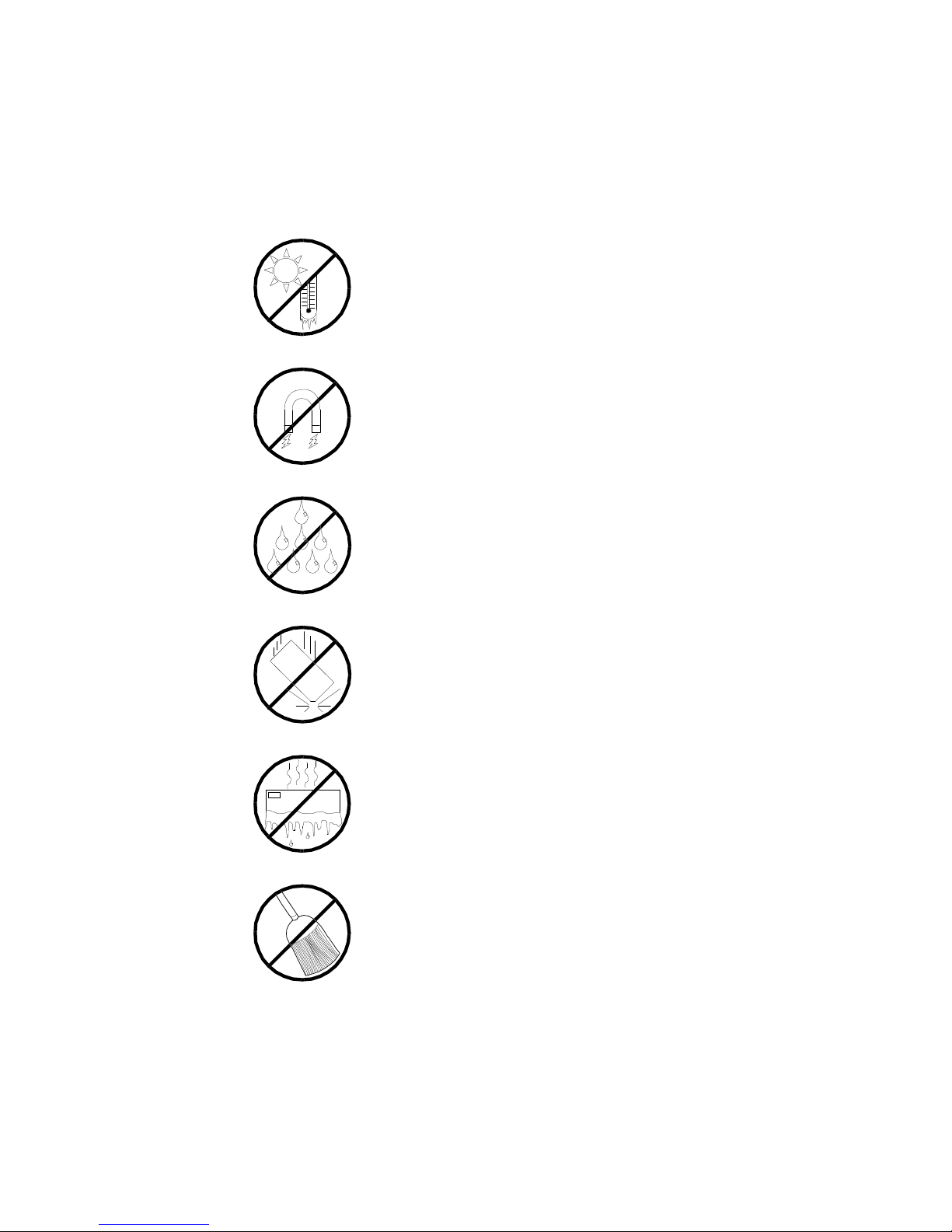
Use the following guidelines to p roperly handle and
care for your system.
Protect the system from extremely low or high temperatures. Let
the system warm (or cool) to room temperature before using it.
Keep the system away from magnetic forces.
Keep the system dry. Do not wash the system with a wet
cloth or pour fluid into it.
Protect the system from being bumped or dropped.
Check the system for condensation. If condensation
exists, allow it to evaporate before powering on the
system.
Keep the system away from dust, sand, and dirt.
Page 8

Bill Graham
Page 9

Contents
Chapter 1 Introduction
Chapter 2 Features
Chapter 3 Setup
Chapter 4 Configuring Your System
Chapter 5 Upgrades and Options
Chapter 6 Problem Solving
Appendix A Cabling
Appendix B Memory Configurations
Glossary
Equipment Log
Page 10

Bill Graham
Page 11

Chapter 1
Introduction
Contents
Organization ...........................................................................1
Notational Conventions ............................................................3
Page 12

Bill Graham
Page 13

Organization
1-1
This guide tells you how to config ure and upgrade your
server. Its goal is to familiarize yo u with your server
and the tasks necessary for system config uration and
upgrading.
Chapter 1
IntroductionIntroduces you to the purpose and
structure of this guide.
Chapter 2
FeaturesGives you an overview of the server and
describes major sy stem compone nts.
Chapter 3
SetupTells you how to select a site, unp ack the
system, get familiar with the system, make cable
connections, and power on the syste m.
Chapter 4
Configuring Your System Tells you how to configure
the system and provides instructions for running the
Resource Configuration Utility (RCU), the BIOS Setup
Utility and the SCSISelect Utility. Chapter 4 also tells
you how to configure system bo ard jumpers to set
specific operating paramete rs.
Chapter 5
Upgrades and OptionsProvides you with instructions
for upgrading your system with optional memory,
options cards, and peripheral devices.
Chapter 6
Problem SolvingContains helpful information for
solving problems that might occur with y our system.
Introduction
Page 14

1-2
Appendix A
System CablingIncludes cabling information for your
system.
Appendix B
Memory ConfigurationsDefines the allowable memory
configurations for your system.
GlossaryDefines the standard acronyms and
technical terms used in this manual.
Equipment LogProvides you with a sample
equipment log for documenting the system configuration
and updates.
Introduction
Page 15

Notational Conventions
The notational conventions liste d below are used
throughout this manual.
F1
A letter, number, symbol, or word in CAPs re presents a
key on your keyboard. For ex ample, the instruction
press F1 means press the key labele d F1 on your
keyboard.
ENTER
The ENTER key is interchangeably used as RETURN
and CARRIAGE RETURN.
CTRL + ALT
Two or three key names, separated by plus sign (s),
indicate multiple-key entries. Fo r example, CTRL +
ALT + DEL means hold down the CTRL and ALT keys
and press the DEL key.
1-3
The special notices listed below are use d throughout
this manual to emphasize specific information:
Warning: Warning indicates a hazard that can cause
!
!
serious personal injury or de ath if the hazard is not
avoided
Caution: Caution indicates a hazard that might cause
personal injury
Introduction
Page 16

1-4
Notice: Notice indicates the potential to damage
equipment or data is present if the user does not take
the necessary precautions recommended by the Notice.
Note: Notes are used to ide ntify or amplify a point to
the reader. A Note may be use d to emphasize a
recommended sequence of steps.
Introduction
Page 17

Chapter 2
Features
Contents
Overview ................................................................................1
Expanding the Server as Needs Grow ..................................2
System Feature Summary...................................................3
Chassis Front Features and Controls........................................4
Status LED Indicator Descriptions .......................................7
Resetting the System .........................................................8
Chassis Rear Features and Controls......................................... 9
Power Supply Status Lamp Descriptions ............................ 11
System Board Features ......................................................... 12
Processor........................................................................ 14
Memory ........................................................................... 14
I/O Expansion Slots .......................................................... 14
Real-Time Clock/Calendar ................................................ 15
BIOS............................................................................... 15
Video .............................................................................. 15
IDE Controller .................................................................. 16
SCSI Controllers .............................................................. 16
Peripheral Controller ........................................................ 16
External Device Connectors.............................................. 17
Keyboard and Mouse ........................................................ 17
Peripheral Devices........................................................... 17
SCSI-2 Hard Drive Bays ................................................... 17
SCSI Drive Hot-swap Backplane........................................ 18
Removable Media Drive Bays ............................................ 19
Power System....................................................................... 20
Server Security ..................................................................... 21
Mechanical Locks and Monitoring ...................................... 21
Software Locks via the BIOS Setup ................................... 21
Hot Swap Power .................................................................... 23
Hot Swap FAN ...................................................................... 24
Bill Graham
Page 18

xxx
Page 19

Overview
2-1
The Server is a modular, multiprocessing se rver based
on the Intel Pentium® II chip set. The chip set
incorporates a modular scaleable architecture that
integrates a 64-bit bus interface with a primary and
secondary Peripheral Component Interconnect (PCI) bus
and an Industry Standard Architecture (ISA) bus. The
architecture supports Symmetrical Multiprocessing
(SMP) and a variety of operating systems. The chassis
and system board have been designed to meet the needs
of the server marketplace.
The combination of computing performance, memo ry
capacity, and integrated I/O provide s a high
performance environment for many app lications
including network servers and multi- user systems.
This server system is designe d for use in applications
where downtime must be minimized. To this end, the
server includes or has the option to include the
following:
■
Optional power system redundancy ; in a system
configured with two pow er supplies, the system will
continue to operate with a single po wer supply
failure.
■
Self-contained power supp ly units that can be easily
installed or removed fro m the back of the chassis.
■
Removable media drive bay s accessible from the
front of the chassis.
■
Hot-swap SCSI disk drive backplane; a f ailed drive
can be removed and a new drive installed w ithout
system power being turned off, if an optional
Redundant Array of Independent Disks (RAID)
controller module is installed.
■
High degree of SCSI disk fault tolerance and
advanced disk array management features through
the use of RAID (Redundant Array of Independent
Disks) technology, if an optional Re dundant Array of
Independent Disks (RAID) controller module is
installed.
Features
Page 20

2-2
■
Hardware monitors (temperature and vo ltage) and
software monitors to indicate failure s.
■
Easy access to all parts for service.
Expanding the Server as Needs Grow
The typ ical minimum system configuration could
include the following:
■
System board with one Pentium II microprocessor
and 32 MB memory.
■
Diskette drive
■
One SCSI hard drive
■
CD-ROM drive
■
Network add-in boards
■
One 330 Watt power supply
■
SCSI drive backplane
■
Five chassis hot swap fan modules ( six fans)
■
Onboard 1 MB video memory.
As serv er/client needs grow, you can ex pand system
processor capacity, memory, drive s, and the number of
power supplies.
■
System board has a processor up grade socket for an
additional processor. The board may contain up to
two processors.
■
System board has two video memory upgrade sockets
(512 KB each) for an additional 1 MB of v ideo
memory.
■
System board supports 4 EDO DIMM devices for a
minimum memory size of 32 MB; total is 512 MB.
Features
Page 21

■
System board has thre e ISA slots, two PCI slo ts, and
one shared PCI\ISA slot for add-in boards. The
system board also has onboard e xternal I/O (serial,
parallel, video) interfaces.
■
Chassis can hold 11 drives: 6 hot-swap bays f or
3 ½-inch ultra wide SCSI-2 hard drives; three
5 ¼-inch half-height bays for removable media
drives with a CD-ROM reader alre ady installed in
one bay; and two 3 ½-inch half-h eight bays with a
diskette drive already installe d in one bay.
■
Chassis supports up to two power sup plies. The
second power supply can be added to provide
redundant power.
System Feature Summary
The following provides a summary of the system
features:
Feature Description
2-3
System board System board based on Pentium II processor technology;
from one to two processors and up to 512 MB of memory
using 128 MB DIMMs.
Add-in board support Rail and back panel slots support up to 6 add-in boards
(three ISA, two PCI, and one shared PCI/ISA).
3 ½-inch diskette drive 3 ½ diskette drive is externally accessible.
Six locations for 3 ½-inch
SCSI-2 hard drives
The hard disk drive bay can hold six 3 ½-inch hot-
swappable ultra wide SCSI-2 hard drives. The bay is
secured behind a lockable metal EMI door; drives can be
swapped in or out of the system without powering it
down, if a Redundant Array of Independent Disks (RAID)
controller module is installed. The array of drives allows
easy setup of optional RAID applications.
Hot swap-capable backplane A hot swap-capable backplane is part of each 3 ½-inch
drive bay assembly for SCSI drives. The backplane is
designed for wide ultra SCSI-2 devices that use the
industry standard 80-pin Single Connector Attach (SCA)
connector. The backplane consists of two rows of three
drive connectors.
Features
Page 22

2-4
Feature Description
Three locations for removable
media drives
Power supply One or two 330 Watt autoranging power supplies are
Three externally accessible 5 ¼-inch half-height bays are
available for diskette, CD-ROM, and/or tape drives.
easily removed/installed for service. In a two-supply
system, the second supply is redundant.
Hot swap-capable cooling
fans
Security Mechanical: Key lock at the front and three metal
Software: utilities, setup BIOS Setup, Resource Configuration Utility, SCSISelect
Each power supply has two integral cooling fans. Six
more fans provide cooling for boards and drives.
padlock loops (one at the back of each side panel and one
across the bottom of each power supply and power supply
cage). One intrusion sensor for the hot-swap SCSI drive
bay EMI door and two power inter-lock sensors one on
each side of the chassis.
BIOS: Password enable.
Utility and Event Log Reader.
Chassis Front Features and Controls
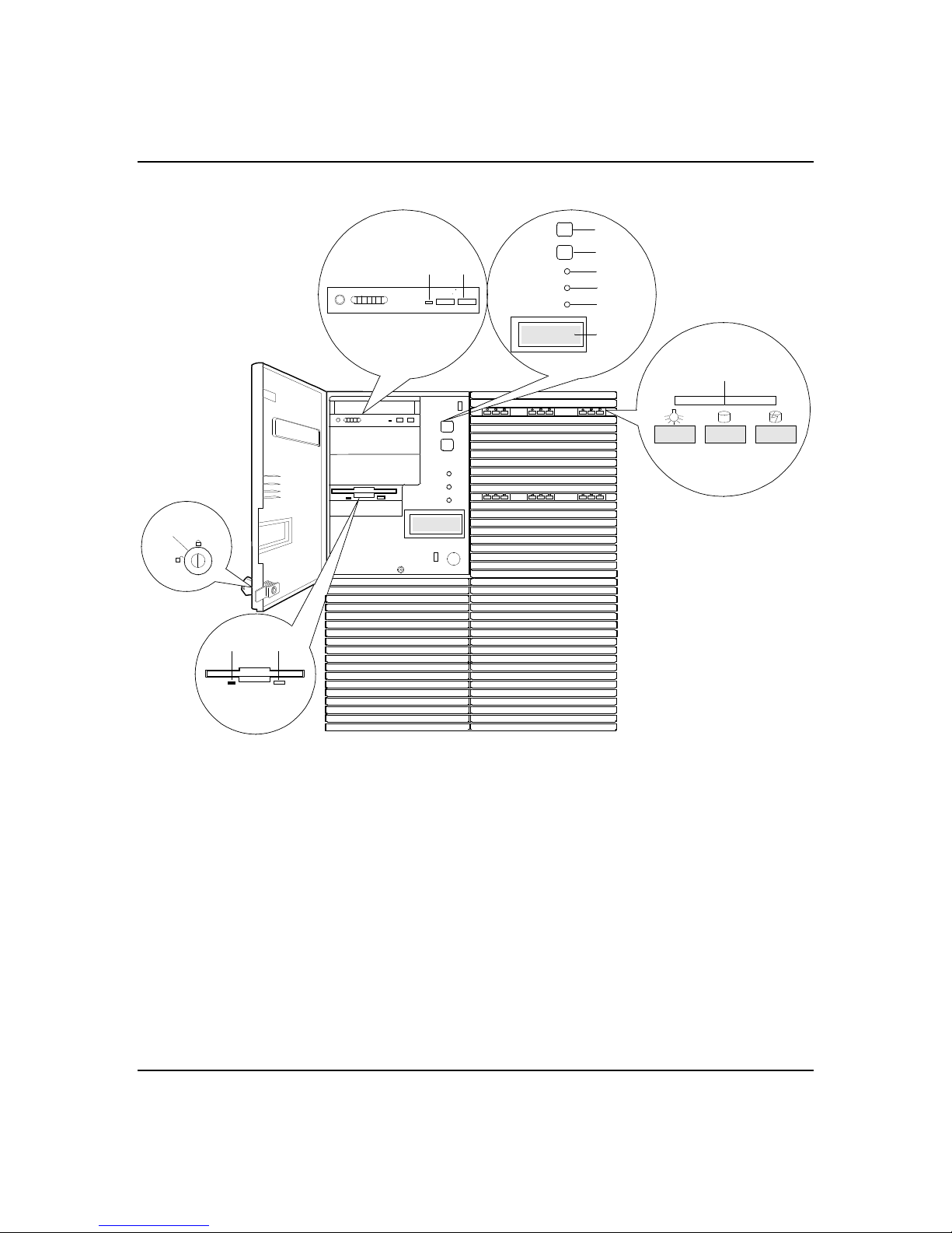
Figu re 2-1 shows the server fro nt chassis features and
controls.
Features
Page 23
2-5
Figure 2-1. Front Chassis Features And Controls
F
G
C B
A
H
I
J
K
L
E
Key lock Secures both front external doors.
A
Load/eject button, CD-ROM
B
reader
Activity light, CD-ROM reader When lit, drive is in use.
C
Ejector button, 3 ½-inch
D
diskette drive
Activity light, 3 ½-inch diskette
E
drive
DC power switch (convex
F
button)
D
Press to load CD and eject CD.
Press to eject diskette.
When lit, drive is in use.
Press to turn system DC power on or off.
Features
Page 24

2-6
Reset switch (concave button) Press to cause a hard reset to the system; the power-
G
on self test (POST) will run.
Power-on LED, green When green, power is present in system (+5 and +12
H
VDC). When off, power is turned off or power source
is disrupted. See Table 2-1 for a list and description
of the LED system status indicators.
System alarm LED When green the system is OK. See Table 2-1 for a list
I
and description of the LED system status indicators.
Drive activity LED When green, internal disk drives are being accessed.
J
See Table 2-1 for a list and description of the LED
system status indicators.
LCD panel Displays information about processor type and
K
system failures (error and diagnostic information).
SCSI drive status LEDs Left to right: Drive present/power on; drive active;
L
drive faulty. Each drive has three LEDs visible above
the bay from the front. See Table 2-2 for a list of
SCSI disk drive status LED indicator descriptions.
Features
Page 25
Status LED Indicator Descriptions
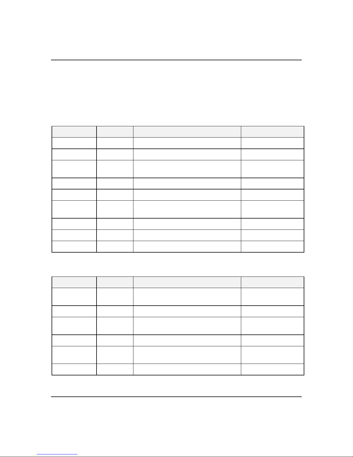
Table 2- 1 lists the system status LED indicators along
with a description of each LED indicato r. Table 2-2 lists
the disk drive status LED panel indicato rs along with a
description of each LED indicator.
Table 2-1. System Status LED Indicators
LED Status Description Response
Power Status Off Power OFF None required (normal)
Green Power ON None required (normal)
Amber System power supply failure Replace failed power
supply module.
System Status Off Power OFF None required (normal)
Green No alarms None required (normal)
2-7
Amber Abnormal condition
(see Table 2-3).
Disk Status Off Not accessing disk drives None required (normal)
Amber Internal disk drive failure Replace disk drive
Green Accessing disk drives None required (normal)
Replace failing part.
Table 2-2. Disk Drive Status LED Panel Indicators
LED Status Description Response
Disk Drive
Power
Green Disk drive power is ON None required (normal)
Disk Drive
Activity
On Accessing disk drives None required (normal
Disk Drive
Status
Amber Internal disk drive failure Replace disk drive.
Off Disk drive power is OFF None required (normal)
Off Not accessing disk drives None required (normal)
Off No alarms None required (normal)
Features
Page 26
2-8
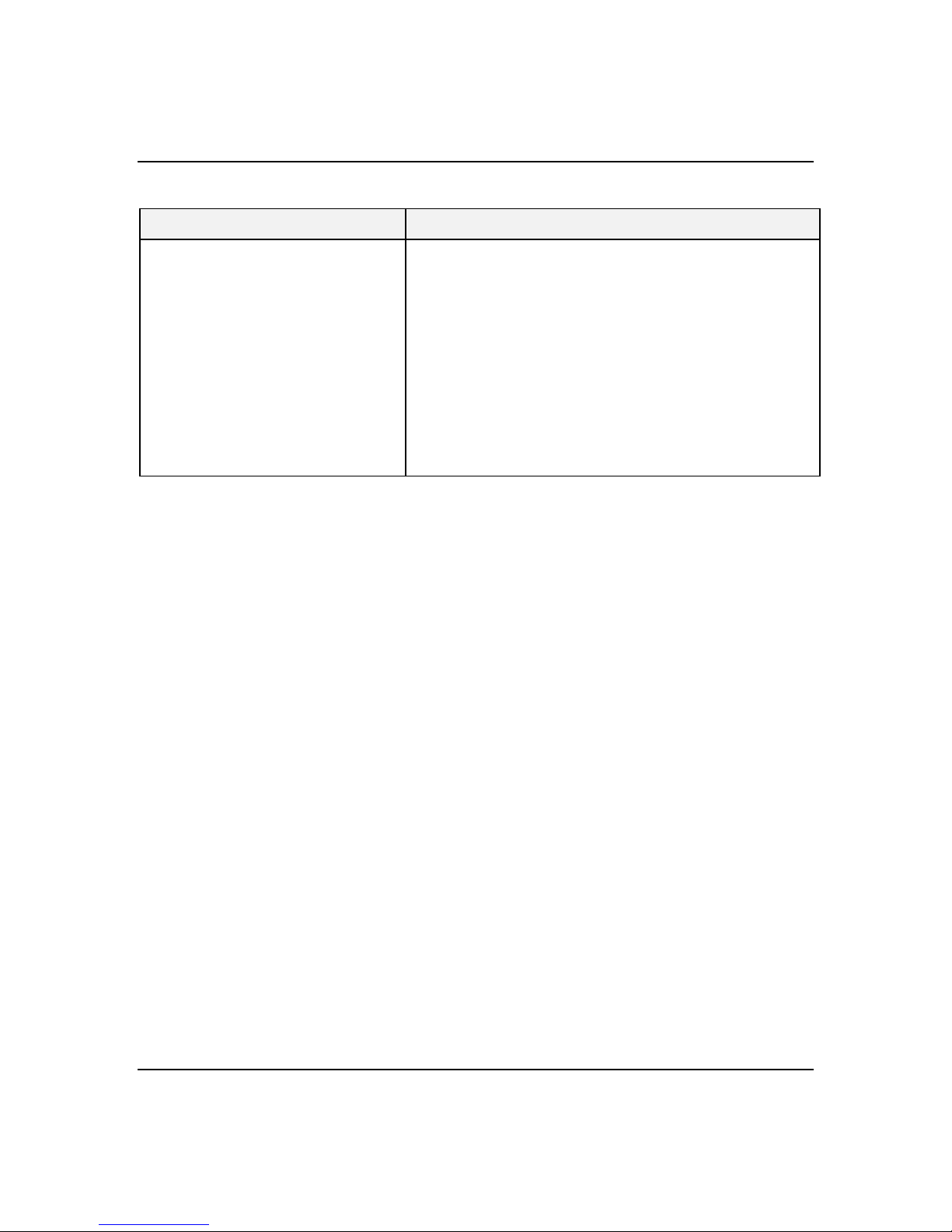
Table 2-3. System Status Abnormal Conditions
LED (Amber) Conditions
System Status Unit fan alarm
Memory multi-bit error
CPU bus error
Thermal sensor (from SCSI distribution board)
Temperature
Voltage
CPU thermal trip
Chassis intrusion (front cover)
PCI bus parity error
PCI System Error
CPU internal error
Watchdog timer timeout
IOCHK
Resetting the System
There are several ways to reset the system:
■
Reset button - pressin g this button clears system
memory, restarts POST, and reloads the o perating
system.
■
Power on/off - turning the power off and then on
with the power button on the front of the system has
the same effect as pushing the Re set button, except
that power is halted to all periph erals.
Features
Page 27
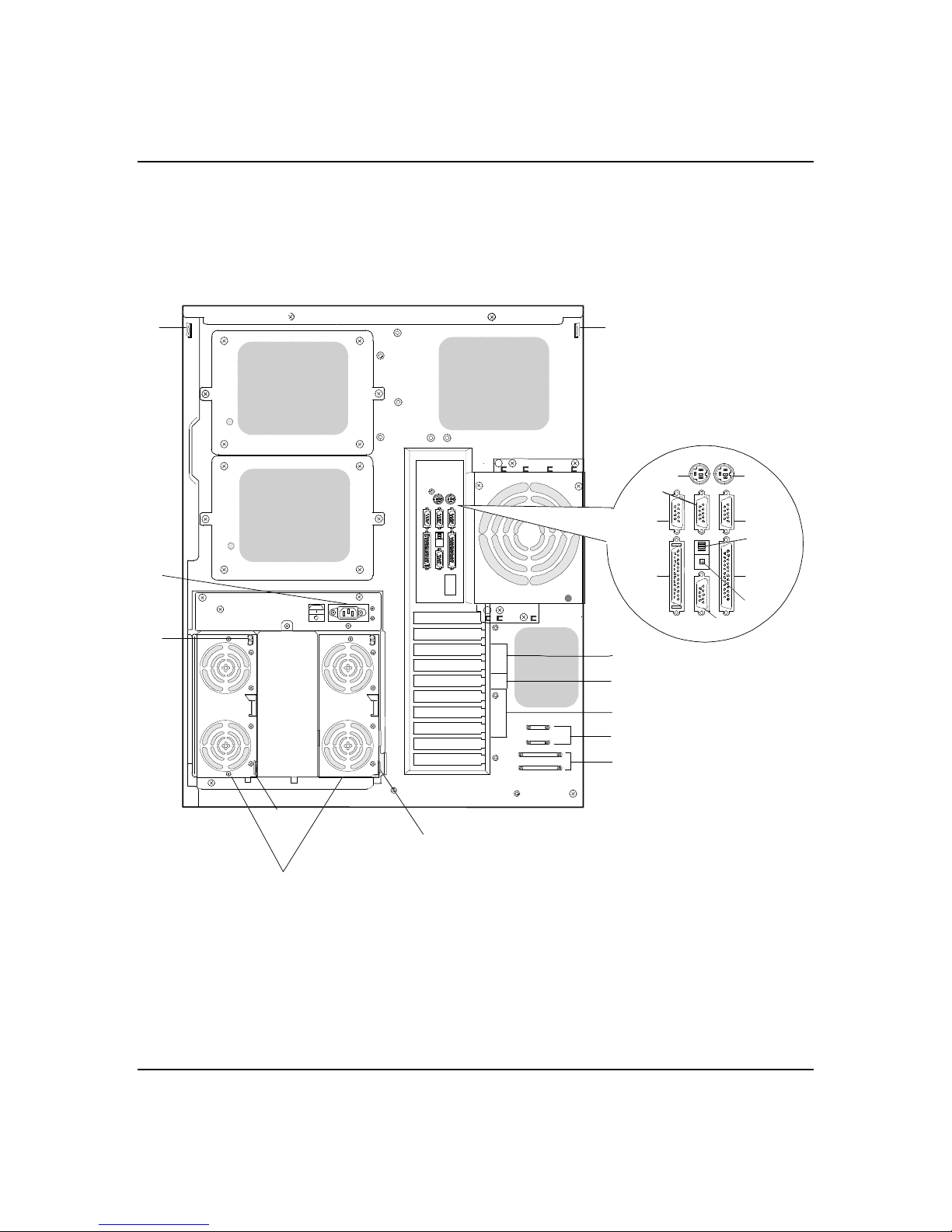
Chassis Rear Features and Controls
Figu re 2-2 shows the server rear chassis fe atures and
controls.
Figure 2-2. Rear Chassis Features And Controls
2-9
C
A
S
C
P
N
R
O
Q
F
G
I
D
E
H
J
M
K
L
C
AC input power
A
connector
Power supplies (two
B
shown)
B
C
One at the top of the power supply cage that supplies AC
power for all the power supplies.
Possible configurations, installed from left most bay:
1 supply (nonredundant)
2 supplies (one redundant)
Features
Page 28

2-10
C
D
E
F
G
H
I
Security padlock loops One on each side at the top rear of the chassis, one on the
power supply cage, and one on each power supply module.
Keyboard PS/2-compatible 6-pin mini-DIN connector.
Mouse PS/2-compatible 6-pin mini-DIN connector.
— Reserved
COM2 COM2 serial port 9-pin connector.
COM1 COM1 serial port 9-pin connector.
External-SCSI Narrow-SCSI 50-pin connector
Function select switches See
J
Dump button See
K
VGA VGA monitor 15-pin connector.
L
Printer LPT1 25-pin Centronics-compatible parallel port connector.
M
PCI slots Two PCI add-in board slot locations.
N
Knockouts Available to route SCSI signals to peripheral boxes.
O
PCI/ISA slot One PCI or ISA add-in board slot location.
P
Knockouts Available to route SCSI signals to peripheral boxes.
Q
ISA slots Three ISA add-in board slot locations.
R
Power supply status
S
lamps
Configuring Switch and Jumper Settings
of this User’s Guide.
Configuring Switch and Jumper Settings
of this User’s Guide.
See Table 2-4 for status descriptions.
in Chapter 4
in Chapter 4
Features
Page 29
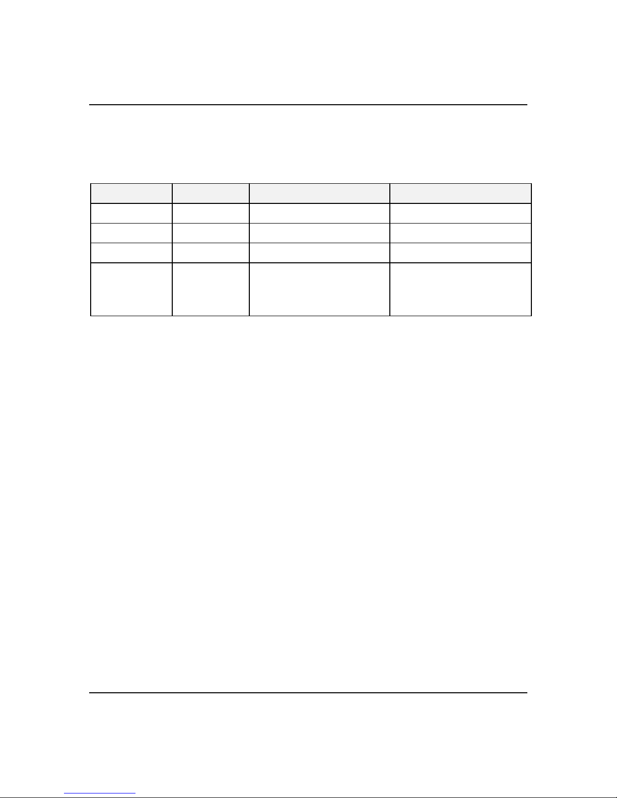
Power Supply Status Lamp Descriptions
Table 2- 4 lists the power supply status lamps.
Table 2-4. Power Supply Status
LED Status Description Response
DC Power Off Power is Off None required (normal)
Green Power is On None required (normal)
Alarm Off No alarm None required (normal)
2-11
Amber
Power failure
Abnormal power temperature
Power FAN alarm
DC-Power alarm
Replace power supply
Clean air passages
Replace power supply
Replace power supply
Features
Page 30

2-12
System Board Features
Figure 2-3 shows the major components on the system
board, while the following summarizes the board
features.
Board set summary Feature description
Multiple processor
support
Upgradable memory Four DIMM sockets on the system board, supporting up to 512
Add-in board support Three dedicated ISA bus slots on the system board. Two
IDE controller Onboard IDE controller.
SCSI controller Two onboard SCSI-2; ultra wide SCSI channel and narrow SCSI
BIOS Flash memory-based BIOS (Basic Input/Output System ) and
Video Integrated super VGA controller ships with 1 MB of video
External device
connectors
Two processor sockets; up to two Pentium II microprocessors on
the system board.
MB memory using 128 MB DIMMs.
dedicated 32-bit PCI slots on the system board. One shared
PCI/ISA slot on the system board.
channel support (PCI-based).
Setup utilities.
memory. For optional 1 MB of video memory, two onboard
upgrade sockets (512 KB each) are available that increases total
video memory size to 2 MB.
Onboard connectors for two serial ports, parallel port, narrow
SCSI port, PS/2-compatible keyboard and mouse, and VGA
monitor.
Clock Real-time clock/calendar (RTC).
System hardware
monitoring
Configuration
utilities
Features
Detects chassis intrusion and contains sensors for temperature,
voltage, and fan failure.
Resource Configuration Utility (RCU), BIOS Setup, SCSISelect
Utility, and Event Log Reader.
Page 31
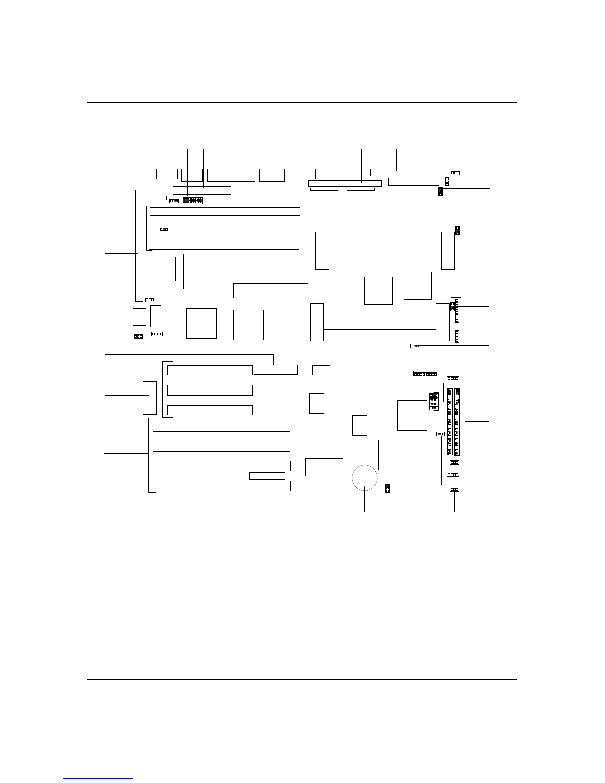
Figure 2-3. System Board Connector and Component Locations
2-13
GI
H
G
F
E
S
D
C
B
J
KML
J41
S
G
V
G
N
O
P
G
Q
G
R
G
G
A
ISA expansion slots
A.
BIOS
B.
PCI expansion slots
C.
RAID connector (reserved)
D.
Optional Video DRAM sockets (2)
E.
I/O riser board connector
F.
Configuration jumpers
G.
DIMM Sockets (4)
H.
IDE connector
I.
Wide SCSI connector
J.
Narrow SCSI connector
K.
TU
Front panel connector
L.
Diskette connector
M.
CPU 2 (optional)
N.
Voltage Module 2 (optio nal)
O.
Voltage Module 1
P.
CPU 1
Q.
Speaker connector
R.
Fan connector
S.
Real time clock battery
T.
Non-volatile memory
U.
Reserved
V.
G
S
Features
Page 32

2-14
Processor
Memory
The system can include one or two Pentium II
processors mounted on the system board. The board also
contains voltage regulators ( Figure 2-3, O and P) to
power each processor. The primary Pentium II processor
plugs into a socket on the this board ( Figure 2-3, Q).
This processor features a 512 KB cache. ECC
generation/checking is provide d for detection and
correction of cache errors. An optional second Pentium
II processor (Figure 2-3, N) enhances performance and
enables
processors acce ss the same memory and I/O space and
tasks can run on either CPU if your operating system
(OS) supports SMP.
The system board contains four 168-p in DIMM sockets
(Figure 2-3, H). The minimum system board
configuration includes 32 MB of system memory . 4
DIMM sockets allow for system me mory expansion to
512 MB. ECC generation/checking is provided for
detection and correction of memory errors.
symmetric multiprocessing (SMP). Both
I/O Expansion Slots
Features
Note:
system. Call your customer service representative for
information.
The server's expansion capabilitie s meet the needs of
file and application servers for hig h performance I/O by
providing a combination of PCI local bus and ISA
connectors. The system board offers two dedicated PCI
slots, three dedicated ISA slots, and one shared PCI/ISA
slot.
The system board contains four ISA I/O (input/o utput)
expansion slots (Figure 2-3, A). The ISA architecture
supports 16-bit memory addre ssing and 16-bit data
transfers.
Only use DIMMs approve d for use in this server
Page 33

The system board also contains three PCI bus I/O
expansion slots (Figure 2-3, C). The PCI architecture
supports 32-bit memory addre ssing and 32-bit data
transfers. One of these slots shares a common chassis
I/O expansion slot with one of the ISA slots; if you use
this slot as a PCI slot, you cannot use it as an ISA slot.
Real-Time Clock/Calendar
The real-time clock provide s system clock/calendar
information stored in a non-volatile memory (NVRAM).
The real-time clock battery (Figure 2- 3, T) provides
power backup for the real-time clock.
BIOS
A BIOS (Figure 2-3, B) and Setup Utility are located in
the Flash EPROM on the system board and include
support for system setup and PCI/ISA Plug-and-Play
auto-configuration.
2-15
Video
A number of security, reliability, and management
features also have been incorporate d to meet vital
server needs.
The system has a high-performance SVGA subsystem
that supports the following:
BIOS compatibility with VGA, EGA, CGA, Hercules
Graphics, and MDA.
1 MB of Video Random Access Memory (VRAM)
expandable to 2 MB (Figure 2-3, E).
16-bit bus for high-speed disp lay memory access.
Hardware accelerated bit block transfer s (BITBLT).
Display power management system.
Supports 72Hz refresh, non-interlaced at: 640x480,
800x600, 1024x768, or 1280x1024 resolutions.
Features
Page 34

2-16
Displays of up to 16M colors at 640x480 and 800x600
resolutions, 64K colors at 1024x768 resolutio ns and
256 colors at 1280x1024 resolutions.
IDE Controller
SCSI Controllers
Note:
performance video modes.
The system includes an IDE interface controller o n the
system board (Figure 2-3, I) supp orting a master and
slave device. This provides suppo rt for the internally
mounted CD-ROM (master device) and an optional slave
device (not IDE hard disk drives).
The system includes two onboard SCSI contro llers,
providing both ultra wide (Figure 2-3, J) and fast
narrow (Figure 2-3, K) SCSI support.
The fast/narrow SCSI-2 controller (Adaptec® AIC- 7860)
supports data paths of 8-bit (fast/narrow SCSI) at a
data transfer rate of 10 MB/sec and the ultra w ide
SCSI-2 controller (Adaptec® AIC-7880) suppo rts data
paths of 16-bit (fast/wide or ultra /w ide SCSI) at a data
transfer rate of 20 MB/sec or 40 MB/sec. O n the PCI
bus, these controllers support burst data transfe r rates
up to the maximum of 133 MB/sec. On this server , the
ultra wide controller is cabled to the six hard d rives in
the SCSI hard drive bays. The fast narrow contro ller
can be cabled to the optional SCSI device s in the 5 1/4inch removable media drive bays and the riser card
(containing external I/O connectors) at the rear of the
system.
SVGA drivers may be required to use the high-
Peripheral Controller
Features
The advanced integrated periph eral controller supports
2 serial ports and one parallel port throug h the I/O
riser board (Figure 2-3, F). The adv anced integrated
peripheral controller also supports the connection of a
diskette drive (Figure 2-3, M) .
Page 35

External Device Connectors
The I/O panel provides connectors f or a PS/2 compatible
mouse and a keyboard, connectors for VGA monitor, 2
serial port connectors, and a parallel port co nnector. It
also provides a narrow SCSI external conne ctor.
Keyboard and Mouse
The ke yboard/mouse controller is PS/2™-c ompatible.
Peripheral Devices
This subsec tion describes the SCSI-2 hard drive bays,
SCSI drive hot-swap backplane, and 5 1/4-inch
removable media drive bays.
SCSI-2 Hard Drive Bays
2-17
The rig ht side of the system contains six bays for 3 1/2inch SCSI-2 hard drives and a hot-swap backplane (see
Figure 2-4). The backplane suppo rts six drives. The
backplanes require an 80-pin single connector
attachment (SCA) connector on the drive s you install.
A driv e carrier is required as part of the hot swap
implementation. A 3 1/2-inch periph eral between 1.0
and 1.6 inches high can be accommodated in each
carrier. A drive is mounted in the carrier with four
fasteners, and the carrier is retained in the chassis by a
locking handle.
A fault light on the front panel board gives a general
indication that there has been a fault o n a hot-swap
drive. Each drive has a set of thre e lights to indicate
the fault or other status: power-on (green LED), activity
(green LED), or fault (yellow LED).
Features
Page 36
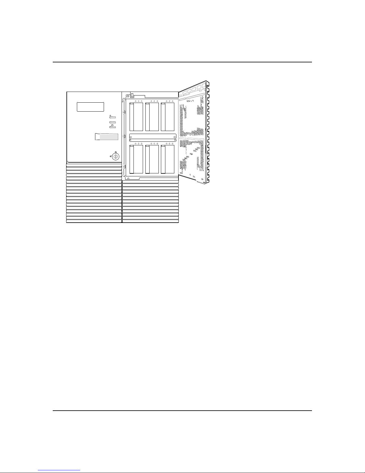
2-18
Figure 2-4. SCSI-2 Hard Drive Bays
Six bays for SCSI drives
(EMI panel and exterior door
shown open)
3
45
2
1
0
SCSI Drive Hot-swap Backplane
The SCSI backp lane is an integral part of the chassis.
The backplane provides control sig nals for six SCSI
peripheral devices (address 0 through 5 in Figure 2-4).
The backplane receives control sign als from the system
board ultra wide SCSI-2 controller channel.
The backp lane has two main functions: SCSI drive
control and system data logging . Drive status is
monitored to detect failing driv es and to control LED
indicators. The backplane features are:
■
Inserting and removing of hard drives while po wer
is on (referred to as “hot swap”)
■
Simplified cable management
■
SCA connectors to simplify inserting and remo ving
hard drives
■
SCSI management of fault LEDs.
Each backplane supports SCSI drives with SCA
connectors.
Features
Page 37

Removable Media Drive Bays
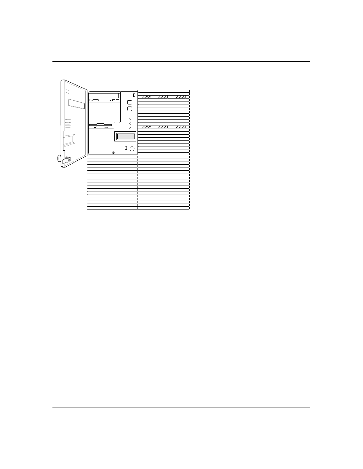
On the left side of the syste m above the diskette d rive,
three 5 1/4-inch half-height bays (see Fig ure 2-5) are
designed for periphe rals with removable media
(diskette, CD-ROM, tape cartridge). Any two adjacent
5 1/4-inch bays can be converted to a single f ull-height
bay. The 5 1/4-inch drives can be removed d irectly from
the front of the chassis after the 5 1/4-inch plastic
frame is removed. The bezel is retaine d by a thumb
screw and snap features and is accessible when the left
side panel and top panel are remov ed. Cosmetic filler
panels and metal EMI shields are installed ov er all
unused 5 1/4-inch bays.
Note:
increased susceptibility to ESD, and coo ling
requirements, hard drives should not be installed in the
5 1/4-inch half-height bays.
On the left side of the system be low the 5 1/4-inch
removable media drive bays, two built-in 3 1/2-inch
bays one of which contains a 3 1/2-inch d iskette drive
that supports both 720 KB and 1.44 MB media (see
Figure 2-5).
Because of the EMI generated by hard drives, the
2-19
Note:
used, a SCSI termination resistors must be installed in
the last SCSI drive of the daisy chain cabling. All other
devices must have terminators removed.
When optional SCSI removable media d evices are
Features
Page 38
2-20
Power System
Figure 2-5. Removable Media Drive Bays
Factory-installed CD-ROM reader plus
two bays for removable media drives.
Factory-installed 3 1/2-inch diskette
drive plus second bay for removable
3 1/2-inch drive.
(Exterior door shown open)
The sy stem may be configured with o ne or two 330 Watt
power supplies. Each supply auto matically switches
between these input voltage ranges:
■
100-120 VAC at 50/60 Hz; 10 A maximum current
■
200-240 VAC at 50/60 Hz; 5 A maximum current
■
The AC input connector is a panel mounted, IEC
320/C20 type connector.
Each supply has the following:
■
Two cooling fans integral with each power supply
enclosure. The fan circuitry implements fan failure
detection.
■
Two indicators: power and alarm.
Features
Page 39

Pow er is drawn equally from all supplie s present (one
or two power supplies). A system with one power supply
can be fully loaded (all drive bays and add-in board
slots filled). In a high-access syste m with two power
supplies, the second supply gives redundancy, because
the load is redistributed if one supply fails.
Server Security
The f ollowing subsections describe mechanical locks and
software locks via the BIOS Setup.
Mechanical Locks and Monitoring
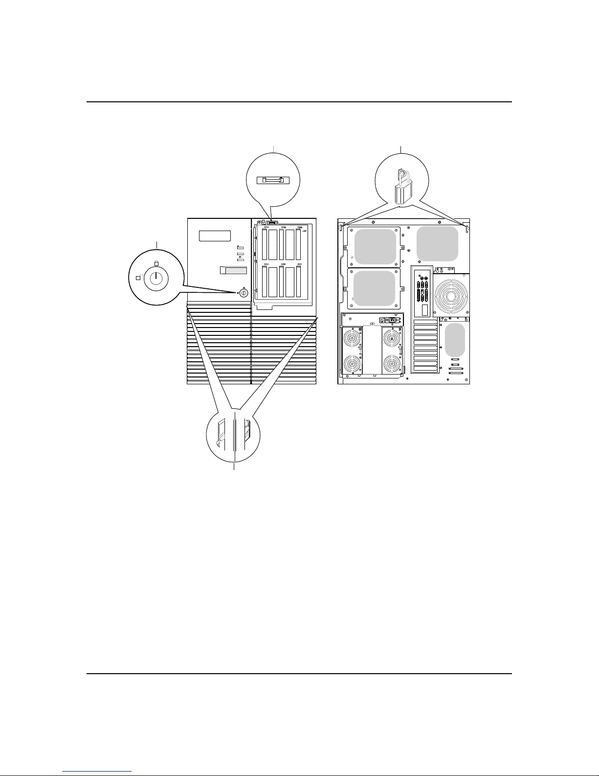
Figure 2-6 shows the server mechanical locks and
monitoring.
Software Locks via the BIOS Setup
2-21
Using Passwords
The BIO S has software features that let you control
access to one or more parts of the system:
■
Set and enable an administrative passwo rd.
■
Set and enable a user passwo rd.
■
Enable password on boot.
■
Disable writing to the diskette d rive when secure
mode is set.
If only a supervisor passwo rd is set and enabled: Enter
this password to boot the server and run the RCU.
If both the user and administrative passw ords are set
and enabled: Enter either one to bo ot the server. Enter
the administrative p assword to access th e RCU or BIOS
Setup to change the system configuratio n.
Features
Page 40
2-22
Figure 2-6. Mechanical Locks and Monitoring
A
B
D
Front panel
A
key lock
Location of
B
internal
intrusion
alarm switch
Location of two
C
internal power
inter-lock
alarm switches
Features
Right
Left
C
Key lock the short front panel door to prevent access to the
power and reset switches. This lock also secures the right-hand
door.
The intrusion alarm switch is present on the SCSI drive bay
door. The switch opens when the drive bay door is opened. An
intrusion alarm signal is transmitted to the system board,
where server management software processes the signal for
security.
The two power inter-lock switches are present on the sides of
the chassis. The switch opens when the side panels are
removed. A power inter-lock signal is transmitted to the
system board controlling a power shut down to the system.
Page 41
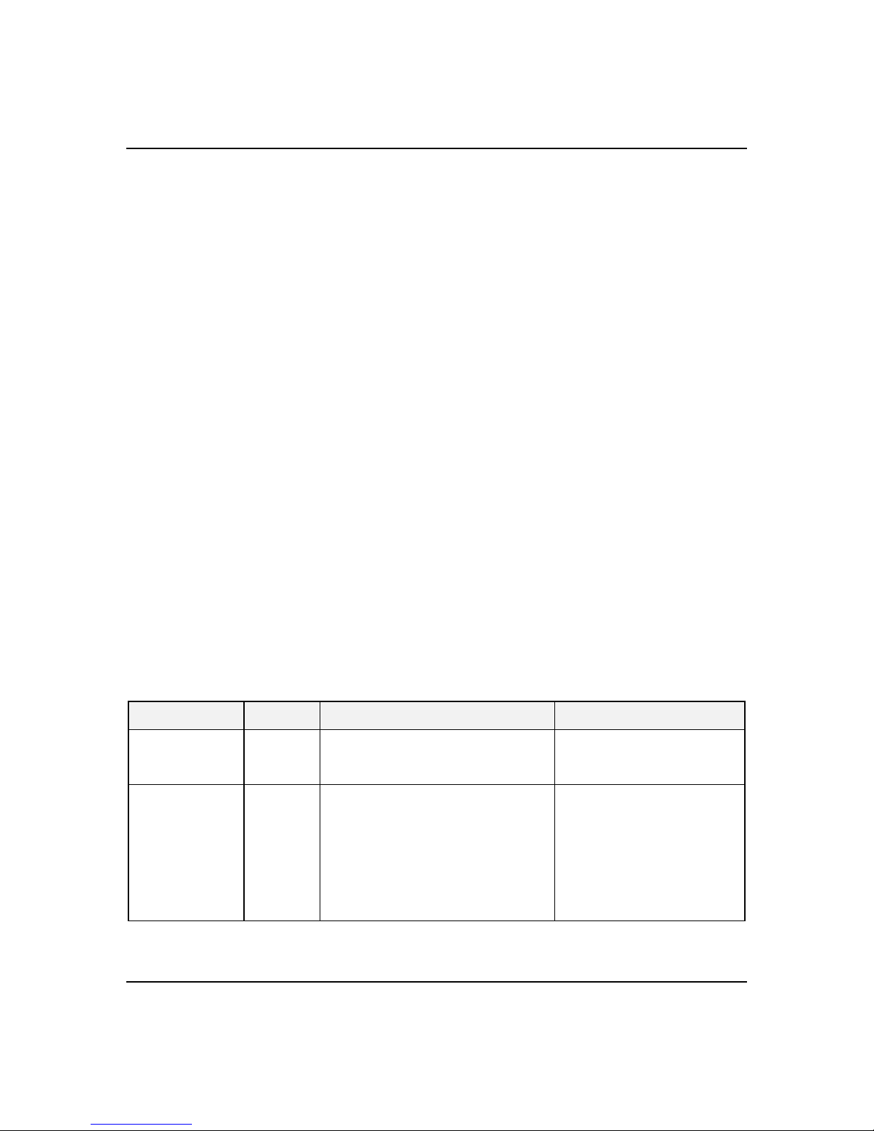
Padlock loops Secure the side covers by using padlocks (not provided). The
D
top cover cannot be removed until the side covers have been
removed.
2-23
Environmental
–
sensors
Hot Swap Power
(Not shown in figure) The system contains sensors to monitor
temperature, voltage, and fan failure.
Pow er supplies are hot-swappable and are easily
removed and installed.
The second optional power supply provides redundant
power so that if one of the two power supplies f ail, the
system will continue to oper ate and the failed power
supply can be hot swapped. That is the failed power
supply is removed and replaced without turning power
off.
The first slot (slot 1) is the basic power sup ply module
slot, the third slot (slot R) is a redundant power sup ply
module slot. The middle slot ( slot 2) is not used on this
system. Each failed power supply mo dule can be
removed without turning off power. Each power supply
module has two LEDs. Table 2-3 shows the Power LED
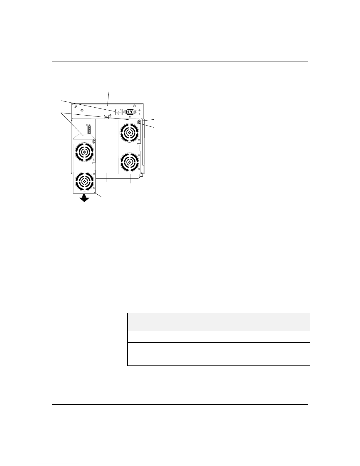
Indicators and Figure 2-7 shows removing the power
supply modules.
Table 2-3. Power LED Indicators
LED Status Description Response
DC-Power Off
Green
Alarm Off
Amber
Power is off
Power is on
No alarm
Power failure
Abnormal Power temperature
Power FAN alarm
DC-Power alarm
None required - normal
None required - normal
None required - normal
Replace Power supply
Clean air passages
Replace Power supply
Replace Power supply
Features
Page 42
2-24
Figure 2-7. Power Supply Module Features
A
B
E
H
F
Hot Swap FAN
A Power cage
B Main power switch
C LED: DC ON (Green)
C
D
G
D LED: Alarm (Amber)
E Power supply modules
F Basic power slot (slot 1)
G Redundant power slot (slot R)
H Reserved for future use (slot 2)
The system has five hot swapp able fan modules (six
fans). The failed fan module can be e asily removed or
replaced without turning power off. Each fan module
has a fan alarm LED and each fan is redundant in
configuration. If one fan fails, its associated fan
changes its rotating speed to high . Table 2-4 lists the
fan redundant pairs. Figure 2-8 shows the f an features
from the front of the chassis and Figure 2-9 shows the
fan features from the rear of the chassis.
Features
Table 2-4. Fan Redundant Pairs
Redundant
Pair
1 CPU Front and CPU Rear
2 Option Board (dual fan)
3 Hard Disk Drive Upper and Hard Disk Drive Lower
Fan Modules
Page 43
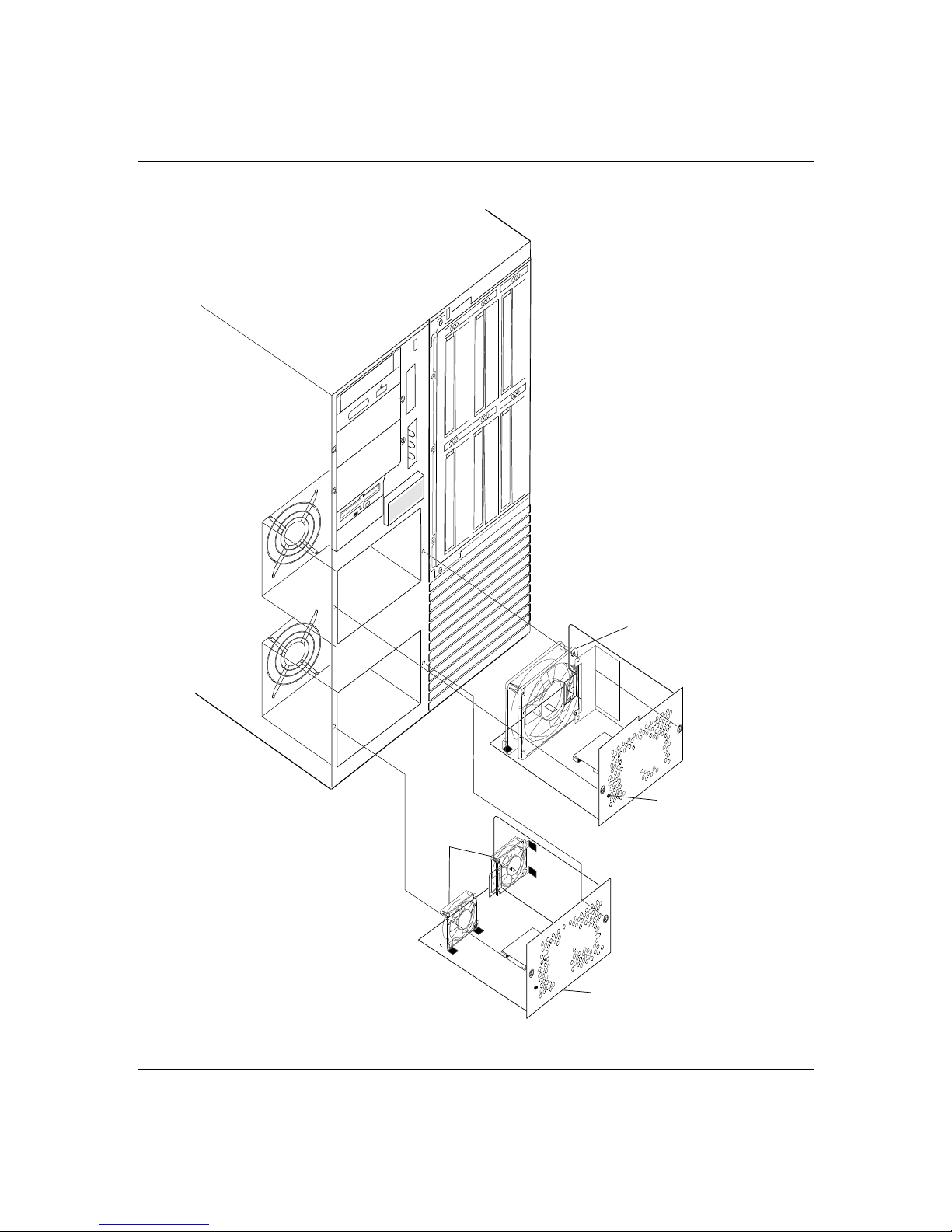
Figure 2-8. The Front Fan Features
2-25
CPU Front Fan Module
(1 Fan)
Option Board
Fan Module
(2 Fans)
Fan LED
Fan LED
Features
Page 44
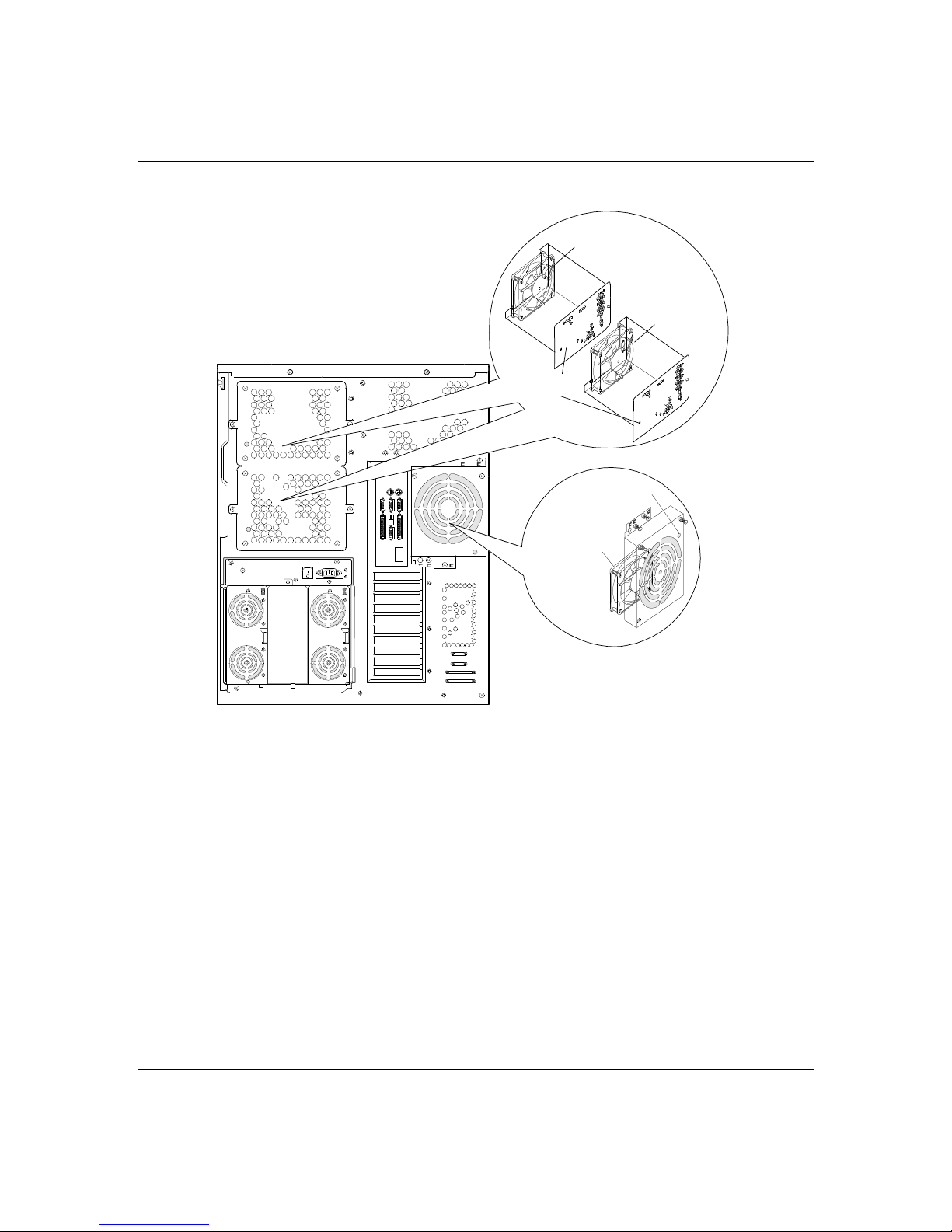
2-26
Figure 2-9. The Rear Fan Features
FAN LED
CPU Rear
Fan Module
(1 Fan)
HDD Upper
Fan Module
(1 Fan)
FAN LED
HDD Lower
Fan Module
(1 Fan)
Features
Page 45

Chapter 3
Setup
Contents
Selecting a Site .......................................................................1
Unpacking the System ............................................................. 2
Getting Familiar with the System ..............................................2
Server Security .......................................................................2
Making Connections ................................................................3
Connecting the Power Cords....................................................5
Powering On Your System .......................................................6
Page 46

xxx
Page 47

Selecting a Site
!
3-1
The system operates reliably in a ty pical office
environment. Choose a site that is:
■ Near grounded, three-pronged power outlets.
Note: Fo r the United States and Canada, this
means a NEMA 5-15R outlets for 100-120 VAC or
NEMA 6-15R outlets for 200-240 VAC. For other
international sites, this means three-pron ged power
outlets applicable for the electrical cod e of the
region.
Caution: Be sure the power service connection is
through a properly grounded outlet
Each power cord can be plugged into a separate
phase of a main AC supply, assuming the circuit is
rated for that load.
Note: For Denmark, the system must be connected
to an AC power source rated at 16 Amps.
■ Clean, dust-free, and well v entilated. Front and rear
ventilating openings kept free o f obstructions. Away
from sources of heat, vibration or p hysical shock
■ Isolated from strong electromagnetic fields and
electrical noise produced by ele ctrical devices (such
as air conditioners, large fans, large electric mo tors,
radio and TV transmitters, and high-frequency
security devices)
■ Spacious enough to pro vide at least five inches (13
centimeters) behind the system and three inches
(eight centimeters) on each side of the system for
proper cooling, airflow, and cable clearance
■ Easily accessible for system maintenance and
installation of system upgrades.
Setup
Page 48

3-2
Unpacking the System
Caution: Your system weighs approximate ly 185
!
pounds (84 kg). To avoid perso nal injury, make sure you
have someone help you lift or move the system
When you receive your system, inspect the shipping
containers prior to unpacking. If the shipping boxes are
damaged, note the damage, and if p ossible, photograph
it for reference. After removing the contents of the
containers, keep the cartons and the packing materials.
If the contents appear damaged when you unpack the
boxes, file a damage claim with the carrier imme diately.
Getting Familiar with the System
Before setting up your system, re fer to Chapter 2 in this
User’s Guide to become f amiliar with the system’s
features, such as the location of yo ur system's security
keylocks and front and rear panel switche s, indicators
and connectors, etc.
Server Security
Setup
Refer to Chapter 2 of this user’s guid e to become
familiar with the system’s mechanical locks, softw are
locks via the BIOS Setup, intrusion alarm, and power
inter-lock switches.
Page 49

Making Connections
Note: If your system normally oper ates without a video
display or keyboard (fo r example, as a network serve r),
you must install a video display and ke yboard to
configure the system. You may remove them after
running the Resource Configuration Utility (RCU). For
information on running the RCU, refer to Configuring
Your System in Chapter 4 of this User’s Guide.
Refer to Figure 3-1 and connect yo ur keyboard, monitor,
and mouse. Connect any external peripheral de vices
such as a printer or modem by following the
instructions included with these devices. To connect
external SCSI cables, refer to Cabling in Appendix A of
this User’s Guide.
Notice: Damage to the system may re sult if the
keyboard cable is inserted or remov ed when power is
applied to the system.
3-3
Caution: Inserting a telephone line connector into a
LAN board RJ-45 port may result in personal inj ury and
equipment damage.
Setup
Page 50
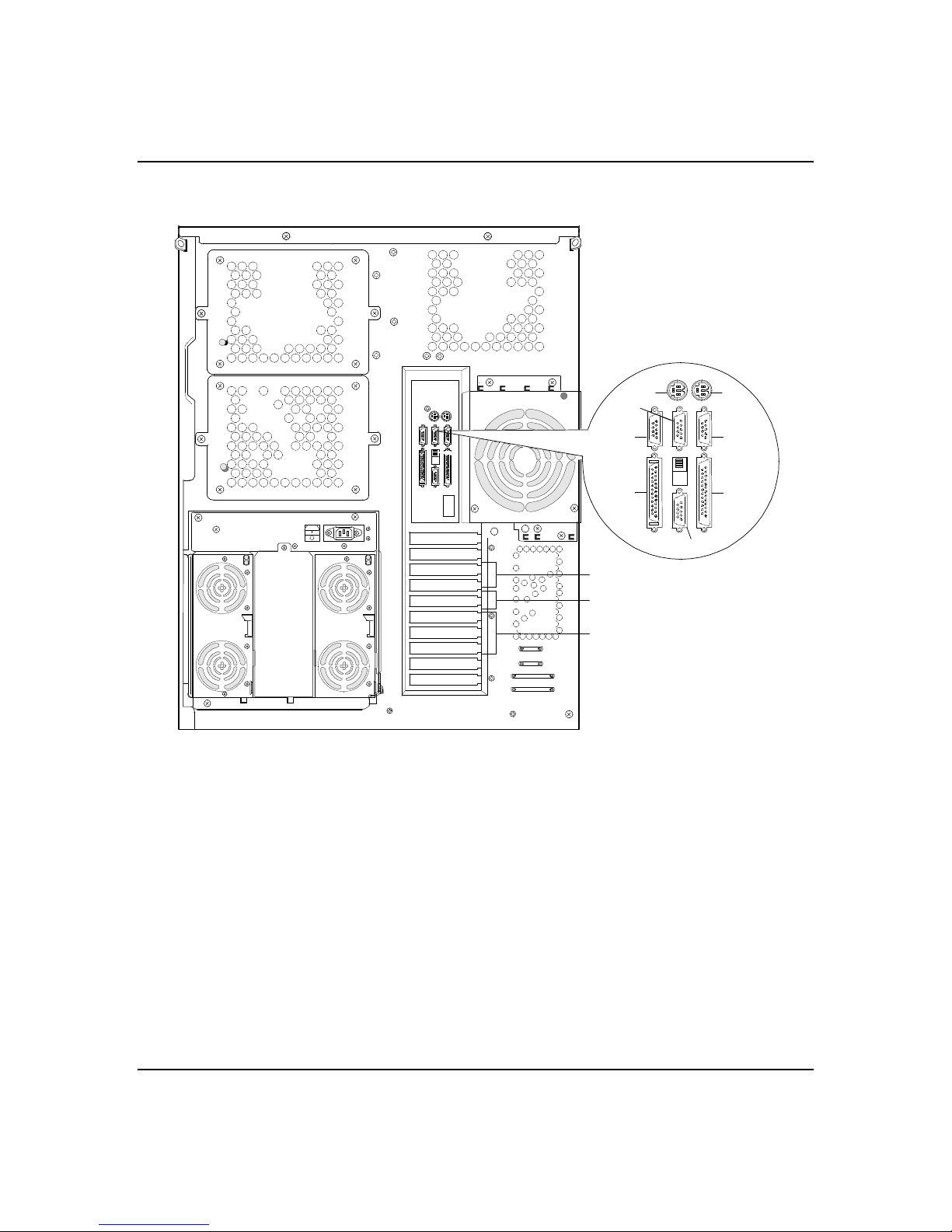
3-4
Figure 3-1. Making Connections
A B
D
C
F
E
H
G
I
J
K
A. Keyboard, PS/2-compatible 6-pin conne ctor
B. Mouse, PS/2-compatible 6-pin connector
C. Reserved, 9-pin connector
D. COM2, serial port 9-pin connector
E. COM1, serial port 9-pin connector
F. External-SCSI, 50-pin high density connector
G. VGA monitor, 15-pin connector
H. Printer, parallel port 25-pin connector
I. PCI slots, Two PCI add-in board slots
J. PCI/ISA slot, One PCI or ISA add-in board slot
K. ISA slots, Three ISA add-in board slots
Setup
Page 51

Connecting the Power Cord
Plug the female end of the AC po wer cord into the input
receptacle on the rear of the power supply cage. Plug
the male end of the power co rd into NEMA 5-15R outlet
for 100-120 VAC or NEMA 6-15R outlet for 200-240
VAC.
If the power cord supplied with the system is not
compatible with the AC wall outlet in your reg ion,
obtain a suitable power cord that meets the fo llowing
criteria.
■ The power cord must be rated for the available AC
voltage and have a current rating that is at least
125% of the current rating of the system.
■ The power cord connector that plugs into the wall
outlet must be terminated in a grounding-typ e male
plug designed for use in your region. It must have
certification marks showing certification by an
agency acceptable in your region.
3-5
■ The power cord connector that plugs into the system
must be an IEC- type CEE-22 female connector.
■ The power cord must be less than 1.8 meters (6.0
feet) long.
Warning: Your system shipped with a power cord. Do
!
not attempt to modify or use the supplied AC power cord
if it is not the exact type required
Setup
Page 52

3-6
Powering On Your System
1. Make sure all external devices, such as a vid eo
display, keyboard, and mouse (op tional) have been
connected, and the power cords are connected.
2. Power on the video display and any other external
devices.
3. Press the push-button power on/off switch on the
front panel. Verify that the powe r-on LED is lit. If it
is not lit, ensure the ac power cords are connected to
a functional ac power source.
After a few seconds your sy stem begins the internal
Power-On Self Tests ( POST). POST automatically
checks the system board, CPU module, me mory,
keyboard, and most installed perip heral devices.
If you have problems powering on your system, refer to
Problem Solving in Chapter 6 of this User’s Guide.
After you have successfully powered on your system,
you can run the installation checklist on the
EXPRESSBUILDER CD-ROM.
Setup
Page 53

Chapter 4
Configuring Your System
Contents
Configuring Your System .........................................................1
Resource Configuration Utility (RCU) ........................................2
Using the RCU...................................................................3
RCU Command Line Parameters ..........................................5
RCU Configuration Settings ................................................6
ISA Board Configuration .....................................................7
BIOS Setup Utility ................................................................. 10
Using the BIOS Setup Utility ............................................. 10
BIOS Setup Configuration Settings.................................... 11
Exiting BIOS Setup ........................................................... 16
Using the Utilities Diskette..................................................... 16
Viewing the Event Log...................................................... 18
SCSISelect Utility............................................................. 19
Using the SCSISelect Utility......................................... 20
SCSISelect Configuration Settings ............................... 21
Exiting SCSISelect ...................................................... 22
Configuring the Optional RAID Controller................................ 23
Configuring I/O Riser Board Function Select Switches ............. 24
Configuring System Board Jumpers ........................................ 27
Before You Begin............................................................. 27
Moving System Board Jumpers ......................................... 31
Updating the BIOS ........................................................... 32
Resetting the CMOS NVRAM ............................................ 33
Clearing and Changing the Password ................................ 33
Page 54

1231231
Billy Graham
Page 55

Configuring Your System
Configuration and setup utilities are used to change
your system configuration. You can configure your
system, as well as option board s you may add to your
system, using the Resource Configuration U tility (RCU)
diskette. Also, several unique syste m parameters are
configured using BIOS Setup which is store d in the
system FLASH memory. A diskette is not ne eded to run
BIOS Setup.
A Utilities diskette contains the SCSISelect Utility and
the Event Log Utility. The Ev ent Log Utility is used to
read stored system eve nt information. The SCSISelect
Utility is used if you need to conf igure the SCSI
controller in your system or to pe rform a SCSI disk
format or verify disk operation of these drives.
If your system has been factory configured, the RCU,
BIOS Setup, or SCSISelect utilities do no t need to be
run unless you want to change the password or security
features, add option boards or de vices, or upgrade your
system board.
4-1
There are some system configuratio n parameters that
are set by jumpers on the sy stem board. However, these
parameters do not usually require change.
This chapter provides procedures for running the RCU,
BIOS Setup, and the Utilities diskette. Also , sections
describing the I/O riser board function switch
configurations and the system board ju mper
configurations are presented. Sev eral configuration
tables are provided in this chapter to re cord changes
you make to the default system configuration.
You use the EXPRESSBUILDER CD-RO M to create the
RCU and Utilities diskettes.
Configuring Your System
Page 56

4-2
Resource Configuration Utility (RCU)
The Resource Configuration Utility is used to configure
your system. The RCU can be used to conf igure the
memory subsystem, peripheral dev ice subsystems, and
interface adapters. RCU recognizes ISA Plug- and-Play
boards and PCI boards and displays their configuration.
ISA (non-Plug and Play) adapter board s must be added
to the RCU configuration to reserve the resources
required by the ISA boards.
After you add options using the RCU, the system
automatically configures and initializes them during
system initialization at boot up.
The RCU stores the configuration information in the
non-volatile memory on your sy stem. When you exit the
RCU the configuration information is written to non-
volatile memory. The RCU also maintains the Setup
configuration, which is stored in the battery -backed
memory. This means that when you exit the RCU, the
Setup and RCU configuration will agree with each
other.
Configuring Your System
Page 57

Using the RCU
4-3
If you are adding a non-Plug and Play ISA option bo ard,
run the RCU before installing the board using
procedures found in the Upgrades and Options chapter
of this guide. If you are upgrad ing system memory, do
so before running the RCU using procedures found in
the Upgrades and Options chapter of this guide. To use
the RCU:
Notice: The system can fail following impro per
configuration. Always save the current settings bef ore
reconfiguring the system.
Note: Because of license restrictio ns, the RCU diskette,
as created by the EXPRESSBUILDER CD-RO M, is not
bootable. In order to use this diske tte, you must make it
bootable.
1 . Power o n t h e s y s t e m .
2. If the d iskette drive is disabled, enable it using the
BIOS Setup utility, explained later in this chapter.
Specify the correct type of diskette drive.
3. Using the EXPRESSBUILDER CD-ROM, create the
RCU diskette. Note that the CD-ROM refers to the
RCU as the SCU.
Note: Perform Step 4 of this procedure the first time
you use the RCU diskette. This step e nables the RCU
diskette to be MS-DOS bootable.
4. Insert the RCU diskette into floppy disk drive A. At
the C:\ prompt type:
SYS A:
Press ENTER. MS-DOS system files are copied onto
the diskette. Your RCU diskette is no w bootable.
5. Start the RCU by rebooting the system, with the
RCU diskette in Drive A. When the RCU banner is
displayed, press ENTER and the System
Configuration Utility Main Menu shown in Table 4-1
is displayed.
Configuring Your System
Page 58
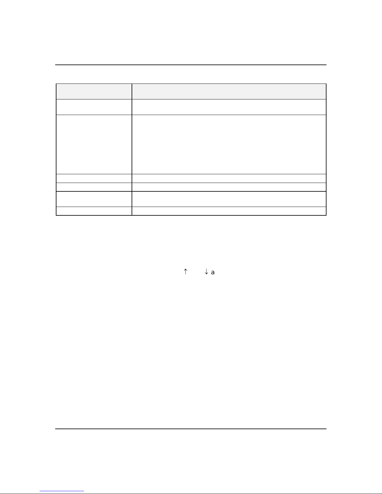
4-4
Table 4-1. Resource Configuration Utility Main Menu
MENU OPTIONS DESCRIPTION
Learn about configuring
your computer
Configure computer Lists automatically detected boards, and enables manually adding, moving
Set date Enables viewing and changing the date that the computer uses.
Set time Enables viewing and changing the time that the computer uses.
Maintain system
configuration diskette
Exit from this utility Exits from the RCU.
Provides basic instructions on resource configuration and using the Help
program.
and removing boards. Plug-and-Play boards don’t require configuration
files. If you ISA boards which require configuration files, use “Add or
remove boards” for a menu to enter or change ISA board configurations.
(Refer to
INSERT adds a board not detected or has not been installed.
DEL removes a selected board.
F7 moves a selected board to a different slot.
Enables viewing and changing Configuration (.CFG) files and System
Configuration Information (SCI) files.
ISA Board Configuration
found later in this chapter).
6. Select Learn about configuring your computer from
the RCU Main Menu and press ENTER if you nee d
information on system configuration. Re ad through
the information and press the F10 key wh en you are
done.
7. Using the and arrows highlight Configure
Computer and press ENTER. The Resource
Configuration Utility Menu shown in Table 4-2
displays. The keys that are active while viewing a
screen, are displayed on the bottom of the screen.
Configuring Your System
Note: Press the F1 key at any time for help and
additional information on each optio n. To return
from help, press the ESC key.
8. Select Step 1: Important Resource Co nfiguration
information and press ENTER to learn more abo ut
the Resource Configuration Utility.
9. Select Step 2 to add an ISA board to your system.
Refer to “ISA Board Configuration” in this chapter.
Page 59
Table 4-2. Resource Configuration Utility Menu
MENU OPTIONS DESCRIPTION
4-5
Step 1. Important Resource
configuration
information.
Step 2. Add or remove boards Lists automatically detected boards, and enables manually
Step 3. View or Edit Details Enables viewing and changing your system configuration
Step 4. Examine Switches or
Print Report
Step 5. Save and Exit Allows you to save your configuration and exits to the
Provides information on the Resource Configuration
program and how it differs from ISA board configuration.
adding, moving and removing boards. Plug-and-Play
boards don’t require configuration files. This list shows all
the boards and options that will be installed in your system.
settings including embedded features, functionality, IRQs,
and port selections. Perform Step 3 only if you need to
change the system default settings.
Enables viewing the required switch and jumper settings
and allows printing of a configuration report.
operating system. You can also exit without saving.
10. Select Step 3 to view your system s configuration
settings. The normal (d efault) RCU settings are
shown in Table 4-3.
RCU Com m an d L i n e P a r a m e t e r s
There are RCU options that can be enable d by starting
the RCU from the command line with the appropriate
switch listed below. To enable an o ption, insert the RCU
diskette in drive A and type A:SD at the MS-DOS
prompt, followed by one of these command line
parameters:
High resolution display. Sets the display mode to 43 lines
H
for an EGA add-in video controller board or to 50 lines for
a VGA board. The default is 25 lines for all add-in video
controller boards.
Monochrome display. The display screens are shown using
M
monochrome attributes, even on a color display. The
default is to display color, unless a monochrome video
display is detected. Use this parameter when you have
redirected the console to one of the onboard serial ports.
Configuring Your System
Page 60
4-6
RCU Configuration Settings
Table 4-3 show s t h e r eco m m end e d RCU s e t t i n g s f or a
sample system and provides a place f or you to record
any changes you make to the settings. To display the
configuration settings, select Step 3 unde r the Resource
Configuration Utility Menu. To edit any of the
configuration parameters, use the and arrows to
highlight the desired configuration parameter and press
ENTER. Pressing F6 at this point, allows you to e dit
any of the parameters resources (IRQs, DMAs, I/O ports
or memory).
Table 4-3. RCU Configurations
MAIN MENU NORMAL SETTING YOUR CONFIGURATION
System Board
Mouse Controller Enabled
RS - 232 COMM Port 1 PORT 3F8h - 3FFh IRQ 4
RS - 232 COMM Port 2 PORT 2F8h - 2FFh IRQ 3
Parallel Port PORT 378h - 37Fh IRQ 7
IDE Controller Enabled
Floppy Controller Enabled
SLOT 1 - PCI Ethernet Controller
PCI Function 1 Enabled
Embedded - PCI SCSI Controller
PCI Function 1 Enabled
Embedded - PCI SCSI Controller
PCI Function 1 Enabled
Embedded - PCI VGA Controller
PCI Function 1 Enabled
Standard VGA Resources Enabled
Configuring Your System
Page 61

ISA Board Configuration
If you want to add a non-Plug and Play ISA bo ard to
your system that is not included in a .cfg file , use the
following procedures to define and add the option board.
It is necessary to define an ISA board to pr event other
boards in the system from using the same IRQ levels,
DMA channels, I/O port addresses, or memory
addresses, that your ISA board uses.
You must run the RCU and add the ISA board to the
configuration before installing the ISA board in the
system, otherwise the resources on the ISA board may
conflict with a Plug-and-Plug board in the system.
BIOS automatically assigns ISA Plug-and-Plug board s
to the next available slot. If the slot d isplayed in
Step 2: “Add or Remove Boards” is not the actual slot, it
can be moved by using the F7 function key .
Notice: IRQ levels, DMA channels, I/O port add resses,
and memory addresses defined using this procedure
should reflec t the same settings de fined by supplie d
jumpers and/or configuration documents.
4-7
1. Insert the RCU diskette into drive A: and power-on
the system. The system boots-up using the RCU
diskette.
2. The RCU Main Menu shown in Table 4-1 is displaye d.
At the Startup Menu, enter choice 2, Configure
Computer.
3. The Resource Configuration Utility Menu shown in
Table 4-2 is displayed. Sele ct Step 2 Add or Remove
Boards and press ENTER.
4. The Step 2: Add or remove boards screen is displayed.
At this screen select Add by pre ssing INSERT.
5. The Add screen is displayed telling you to locate the
diskette that contains the .cfg file fo r the board.
Press ENTER at this screen.
6. The Select a Configuration (CFG) file to add screen is
displayed. At this screen se lect Not Listed by
pressing F5.
Configuring Your System
Page 62
4-8
7. The Add a board without a .cfg file screen is
displayed. Read through the information and pre ss
ENTER. The Add a board without a .cfg file screen
reappears. When the screen re appears select Create
.cfg file and press ENTER.
8. The Create A Board CFG File screen is displayed. At
this screen enter the board descriptio n and
manufacturer and press ENTER.
9. The New Board Setup screen is displayed. Using the
scrollable list select the resources used by the new
ISA board. Table 4-4 provides a place fo r you to
record the configuration you assign to the board.
10. Press F10 when yo u are finished selecting the
resources used by the new ISA board.
11. The View Current Settings screen is display ed. Press
ENTER to save the current setting s.
12. The Add confirmation screen is displayed . Review
the manufacture r’s comments and press ENTER.
Table 4-4. ISA Board Configurations
ISA BOARD DEFINITIONS YOUR CONFIGURATION
Board Description:
Manufacturer:
Interrupts
DMA Channels
Port address
Start
End
Memory address
Start
Length
Slot
(Select from scrollable list)
(Select from scrollable list)
Configuring Your System
Page 63

4-9
13. The Add screen is displayed . Select the slot in which
you want to install the board and pre ss ENTER.
Note: If the board you add causes a conflict in the
configuration, a Caution message is displayed . Press
ENTER at the message. This leads you to the
screens that allow you to resolv e the conflict.
14. The Step 2: Add or remove boards screen is
displayed. At this screen se lect Done by pressing
F10.
15. The Steps in configuring your computer screen is
displayed. At this screen select “Step 4: Examine
switches or print report” and press ENTER.
16. The Step 4: Examine switches or print report screen
is displayed. The boards marked with an arrow
indicate that the boards in your system may have
jumpers and switches that you must physically ve rify
or that a software statement with ad ditional
information about the board is provide d. Select Done
by pressing F10.
Note: If the ISA board you are adding to the
configuration does not have switches, jump ers,
software statements or connection inf ormation, an
Information message appears on scree n. Press
ENTER and proceed to the next step.
17. The Steps in configuring your computer screen is
displayed. At this screen select “Step 5: Save and
exit” and press ENTER.
18. The Save and exit screen is displayed. At this screen
select “Save the configuration and restart the
computer” and press ENTER.
19. The Reboot screen is displaye d. At this screen press
ENTER.
20. Now that yo u have reserv ed the system re sources,
you can install the ISA board.
Configuring Your System
Page 64
4-10
BIOS Setup Utility
The BIOS Setup Utility, like the RCU, is used to change
system configuration parameters. This utility has some
unique parameters and many parameters that are also
configurable with the RCU. The utility is resident in
the system FLASH memory and does not require a
diskette or an operating system present to run.
However, parameters set with the BIOS Setup Utility
that can also be set with the RCU, will be ove rwritten
by the RCU the next time the RCU is run.
Using the BIOS Setup Utility
You access the BIOS Setup utility when you turn o n or
reboot your system. To run the BIOS Setup U tility,
perform the following procedure:
1. Powe r-on or reboot the system . BIOS displays the
following:
Press <F2> to enter SETUP
2. Press F2. The BIOS Setup Utility starts and the
Main Menu is displayed. The menu bar at the top of
the Main Menu lists the following sele ctions:
Menu Use
Main Use this menu for basic system configuration.
Advanced Use this menu for setting the Advanced Features
available on your system.
Security Use this menu to set User and Supervisor Passwords
and the Backup and Virus-Check reminders.
Server Use this menu for configuring Server Features.
Exit Exits the current menu.
Use the arrow keys to select a menu or an ite m on a
displayed menu. Press the value ke ys (listed in the
table below) to cycle through the allo wable values
for the selected field. Use the Exit menu’s “Save
Values” selection to save the current values on all
the menus.
Configuring Your System
Page 65
4-11
To display a submenu, position the curso r on a
selection that has a submenu and press ENTER.
Selections with submenus are preceded by an arrow.
Refer to the following table fo r information on the
keys you use with Setup. These key s are also listed
at the bottom of the Se tup menu.
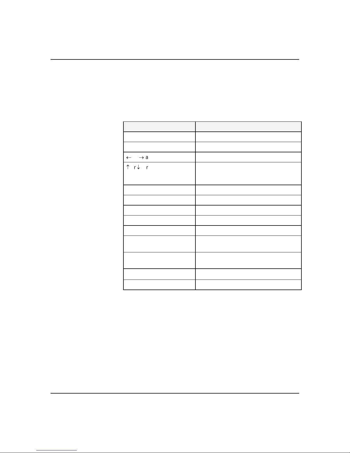
Key Function in Setup Menu
F1 or Alt-H General Help window.
ESC Exit the current menu.
or arrow keys Select a different menu.
or arrow keys Move cursor up and down. The cursor
moves only to the settings that you can
change.
TAB or SHIFT-TAB Cycle cursor up and down.
HOME or END Move cursor to top or bottom of window.
PAGE UP or PAGE DOWN Move cursor to next or previous page.
F5 or - Select the previous value for the field.
F6 or + or SPACE Select the next value for the field.
F9 Load default configuration values for this
F10 Load previous configuration values for this
ENTER
ALT-R Refresh the screen.
BIOS Setup Configuration Settings
Table 4-5 sh ows t h e n orm a l s e t t i n g s f or t h e B I O S S etu p
Utility and provides a place for yo u to record any
changes you make to these settings.
menu.
menu.
Execute command or Select
submenu.
➨
Configuring Your System
Page 66

4-12
Table 4-5. BIOS Setup Configurations
MENU PARAMETER NAME NORMAL SETTING
OR DISPLAY ONLY
MAIN MENU
System Time
Enter current time (hour, minutes, seconds on
24 hour clock).
System Date
Enter current date.
Language
Use +/- to change values; indicates the
language used by Setup.
*
Diskette A:
Use +/- to change values; indicates the type of
diskette drive installed.
*
Diskette B:
Use +/- to change values; indicates the type of
diskette drive installed.
**
IDE Adapter 0 Master
**
IDE Adapter 0 Slave
Video System
Memory Cache
Press ENTER for menu.
Memory Cache Enabled
Cache System BIOS Area Write Protect
Cache Video BIOS Area Write Protect
Cache Base 0 - 512K Write Back
Cache Base 512K - 640K Write Back
CacheExtended Memory Area Write Back
*Cache Memory Regions
Cache C800-CBFF Uncached
Cache CC00-CFFF Uncached
Cache D000-D3FF Uncached
Cache D400-D7FF Uncached
Cache D800-DBFF Uncached
Cache DC00-DFFF Uncached
Current Time
Current Date
English
1.44MB, 3 1/2”
Not Installed
CD-ROM
None
VGA
YOUR
CONFIGURATION
* This parameter will be overwritten by the RCU setting.
** BIOS does not display the attached slave (tape) device, only the master (CD-ROM) is reported.
Configuring Your System
Page 67

Table 4-5. BIOS Setup Configurations (Continued)
4-13
MAIN MENU PARAMETER NAME NORMAL SETTING
OR DISPLAY ONLY
Memory Shadow
Press ENTER for menu.
System Shadow Enabled
Video Shadow Enabled
*Regions with Legacy Expansion ROMs
Boot Sequence
Press ENTER for menu.
Boot Sequence A: then C:
SETUP Prompt Enabled
POST Errors Enabled
Floppy Check Disabled
Numlock
Press ENTER for menu.
Numlock On
Key Click Disabled
Key Board auto-repeat rate 30/sec
Key Board auto-repeat delay ½ sec
Base Memory:
Extended Memory:
A: then C:
On
640 KB
127 MB
YOUR
CONFIGURATION
ADVANCED MENU
Integrated Peripherals
Press ENTER for menu.
Serial Port 1 3F8, IRQ 4
*
Serial Port 2 2F8, IRQ 3
*
*Parallel Port 378, IRQ 7
Parallel Mode Bi-directional
Diskette Controller Enabled
IDE Adapter Enabled
Mouse Enabled
Memory Reconfiguration
Press ENTER for menu.
Memory Reconfiguration Enabled
* This parameter will be overwritten by the RCU setting.
Configuring Your System
Page 68

4-14
Table 4-5. BIOS Setup Configurations (Continued)
MENU PARAMETER NAME DEFAULT SETTING
OR DISPLAY ONLY
DIMM J20 - Row #1 Status Normal
Row #2 Status None
DIMM J19 - Row #3 Status None
Row #4 Status None
DIMM J18 - Row #5 Status None
Row #6 Status None
DIMM J17 - Row #7 Status None
Row #8 Status None
Memory Row Errors Clear Press ENTER
Memory Configuration Message Enabled
Memory Warning POST Error Enabled
CPU Reconfiguration
Press ENTER for menu.
CPU Reconfigure Enabled
CPU #1 Status Normal
CPU #2 Status None
Clear CPU Errors Press ENTER
CPU Error Pause Enable
**SMB Configuration
Press ENTER for menu.
ITF Monitoring Observation OptROM - END
Boot Monitoring Disabled
Boot Monitoring timeout period 5
Advanced Chipset Control
Press ENTER for menu.
DRAM Speed 60ns
DMA Aliasing Enabled
8-bit I/O Recovery 4.5
16 bit I/O Recovery 4.5
Use Mutiprocessor Specification
1.4
** Reserved for future use.
YOUR
CONFIGURATION
Configuring Your System
Page 69
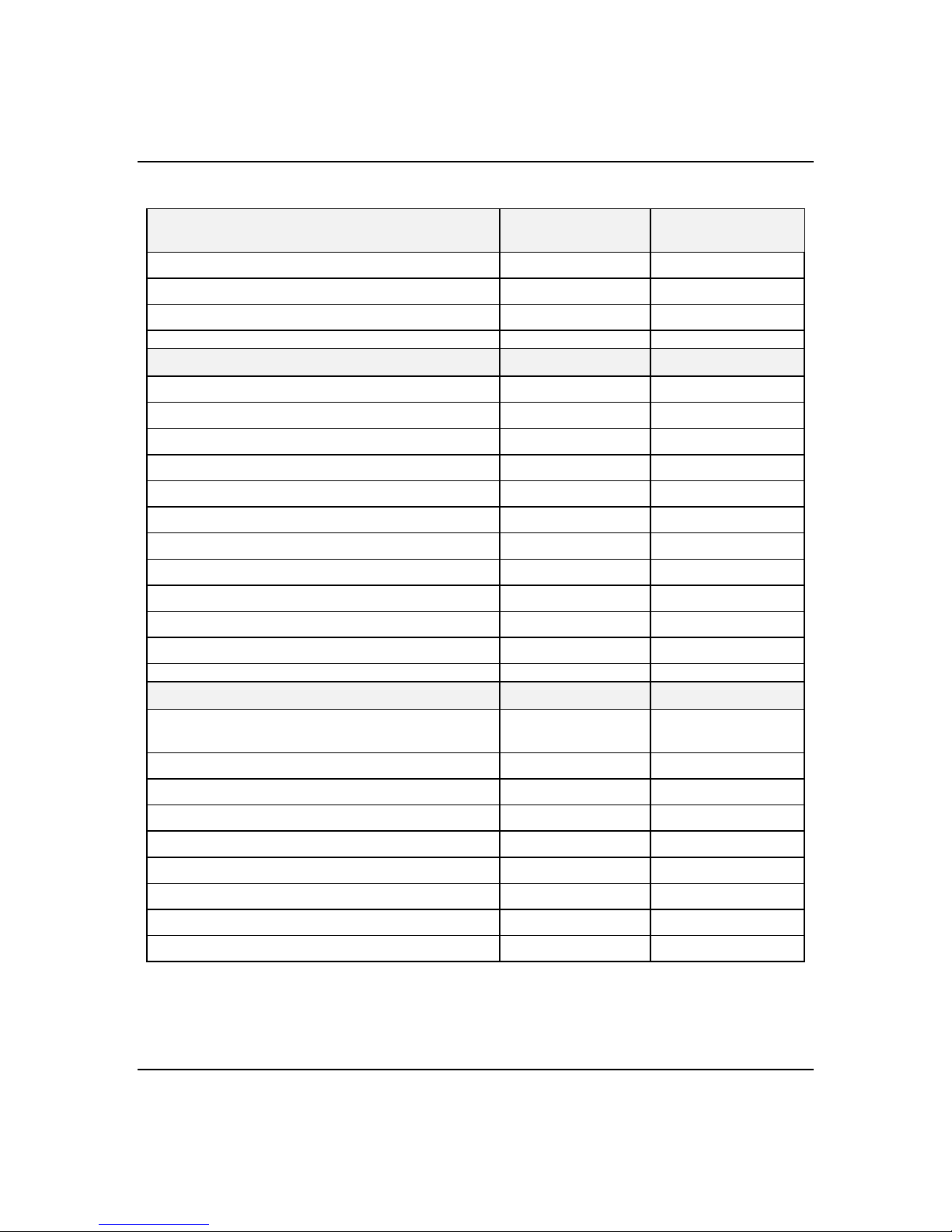
Table 4-5. BIOS Setup Configurations (Continued)
4-15
MENU PARAMETER NAME DEFAULT SETTING
OR DISPLAY ONLY
Plug & Play O/S
Reset Configuration Data
Pentium II BIOS Update
SECURITY MENU
Supervisor Password is: Disabled
User Password is: Disabled
*Set Supervisor Password
Set User Password
**
Password on boot
**
Diskette Write
**
Diskette access
System backup reminder
Execute User ROM
Allow SCSI Select
Power Switch Mask
No
No
Enabled
Press ENTER.
Press ENTER.
Disabled
Normal
Supervisor
Disabled
Disabled
Enabled
Unmasked
YOUR
CONFIGURATION
SERVER MENU
Thermal Sensor
Press ENTER for menu.
Thermal Sensor Enabled
Upper Limit 55
Lower Limit 7
ESM ASIC Interrupt
SMI
Event Log Initialization
Clear Event Log
Console Redirect Port
IRQ 13
Enabled
Disabled
No
Disabled
* Enabling supervisor password requires a password for entering SETUP.
** These parameters require prior setting of supervisor password.
Configuring Your System
Page 70
4-16
Exiting BIOS Setup
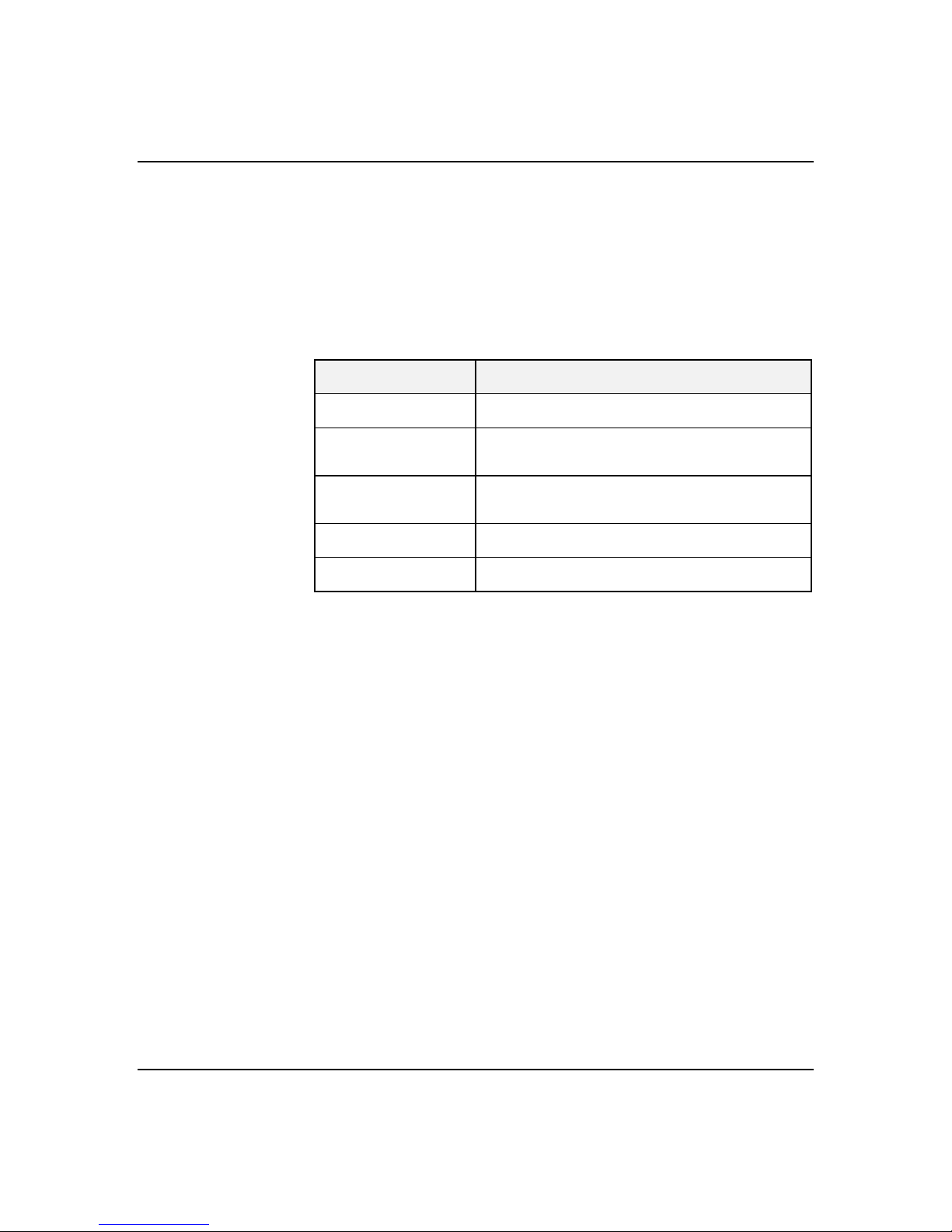
To exit Setup, select Exit from the menu bar to display
the Exit Setup menu .
The following table describes the options on this menu.
Note that ESC does not exit this menu. You must sele ct
one of the items from the menu or menu bar to exit this
menu.
SELECTION DESCRIPTION
Save changes and
Exit
Exit without Saving
Changes
Get Default Values
Load Previous
Values
Save Changes
Using the Utilities Diskette
The utilities diskette contains the SCSISelect U tility
and an Event Log Reader Utility .
Note: Because of license restrictio ns, the Utilities
diskette, as created by the EXPRESSBUILD ER CDROM, is not bootable. In order to use this diskette, you
must make it bootable.
To run the Utilities diskette, perform the f ollowing
procedure:
Stores the selections displayed in the menus in
CMOS and exits the Setup program.
Exits the program without saving any changes you
have made in this session. Previous selections
remain in effect.
Displays default values for all Setup menus. Useful
if BIOS detects a problem with the values stored in
CMOS.
Reverts to previously saved values if the new
values have not been saved to CMOS.
Stores the current selections without exiting the
Setup program.
Configuring Your System
Note: Perform Step 2 of this procedure the first time
you use the utilities d iskette. This step enables the
diskette to be MS-DOS bootable.
1. Using the EXPRESSBUILDER CD-ROM, create the
Utilities diskette.
Page 71
2. Insert the Utilities diskette into floppy disk drive A.
At the C:\prompt type:
SYS A:
Press ENTER. MS-DOS system files are copied onto
the diskette. Your Utilities diske tte is now bootable.
3. Reboot the system w ith the Utilities diskette in
Drive A.
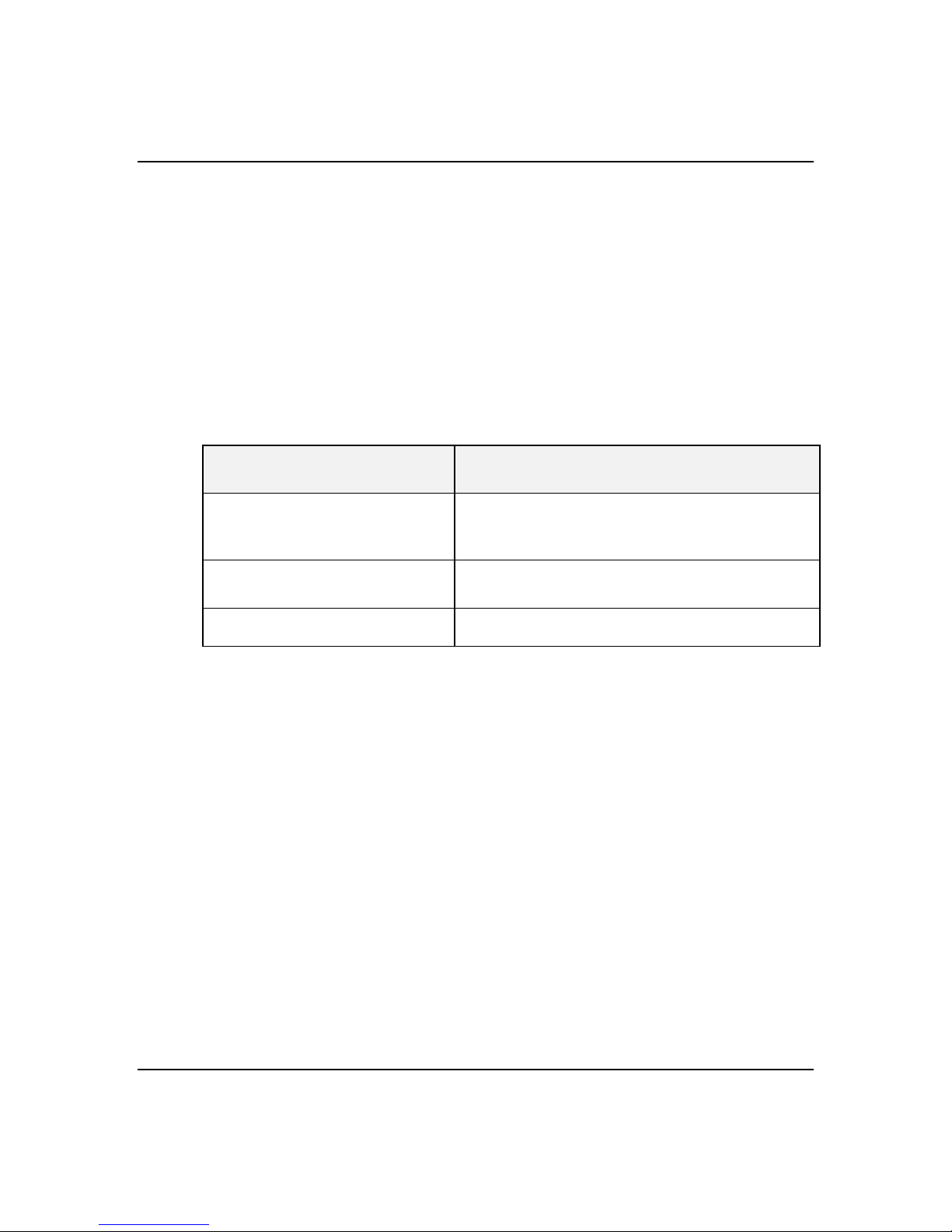
4. The MS-DOS Startup Menu displays. See Table 4-6.
Table 4-6. MS-DOS Startup Menu
MENU OPTIONS DESCRIPTION
4-17
1. Read the System Even t
Log.
2. Execute AIC-78xx
SCSISelect Utility.
3. Exit to DOS. Exits Utilities and returns to A: prompt.
Executes the Log Display Utility which
displays any events stored in the system
log area.
Loads the SCSISelect Utility and di splays
the current configurations.
Configuring Your System
Page 72
4-18
Viewing the Event Log
The system Event Log Utility d isplays information on
the events stored in the system log area. The
information stored includes the name of the event, the
date and time the eve nt occurred and data pertine nt to
the event. Event data may include POST error codes
that reflect hardware errors or software conflicts within
the system.
Note: Refer to Chapter 5 Problem Solving for
definitions on all POST error co des.
To view the Event Log, perform the following procedure:
1. Insert the bootable Utilities diskette into floppy disk
2. Power-on the system. The system boots up.
3. The MS-DOS Startup Menu displays. See Table 4-6.
4. Se lect 1. Read the System Event Log from the MS-
drive A.
DOS Startup Menu.
5. The System Event Log Utility starts. The System
Event Log Utility screen is disp layed. The following
screen choices are available.
SCREEN DESCRIPTION
File
Saves the Event Log and System information to
a file.
ElogInfo
SystemInfo
Event log
Clear Event log
Help
Exit
Displays Event Log information such as: date, time,
and number of times the log was erased; major and
minor revision level; and amount of memory used by
the event log.
Displays system information such as: system model;
processor type and speed; ROM, SCSI and video
BIOS version; number of ISA and PCI slots; total
system memory size; and serial and parallel port
configuration.
Displays the Event Log data.
Clears the Event Log data.
Description of information in this table.
Exits the
System Event Log Utility.
Configuring Your System
Page 73

SCSISelect Utility
4-19
To select an option from the System Event Log
Utility screen, use and to highlight the item
and press ENTER.
To exit the menu item, press ESC.
Your system board includes 2 integrate d SCSI host
controllers used to manage SCSI de vices in your system.
The AIC7880 wide SCSI controller provide s support for
four internally mounted ultra/wide hard disk d rives.
The AIC7860 narrow SCSI controller provides supp ort
for internally mounted optional de vices as well as
externally connected devices.
The integrated SCSI host controller is config ured using
the SCSISelect utility. Use the SCSISelec t utility to:
■
Change the SCSI host adapters default values.
■
Check and/or change SCSI device settings for a
particular device.
■
Change the maximum SCSI bus transfer rate.
■
Perform low-level formatting on SCSI disk devices.
■
Perform verify operations on SCSI disk devices.
When disabling access to the SCSISelect Utility , the
SCSISelect utility should be used in conjunction with
the BIOS Setup utility. Changing the BIOS Setup
utility “Allow SCSI Select” parameter to Disabled
prevents the use of the SCSI Select utility via Ctrl-A,
but the “Press <Ctrl-A> for SCSI Select” prompt is still
displayed. Changing the SCSISelect utility “Display
<Ctrl-A> Message During BIOS Initialization”
parameter to Disabled prev ents the prompt from be ing
displayed. In combination these parameters can be use d
to prevent access to the SCSISe lect utility during boot.
Configuring Your System
Page 74
4-20
Using the SCSISelect Utility
To run the SCSISelect Utility, perform the fo llowing
procedure:
1. Insert the bootable Utilities diskette into floppy disk
drive A.
2. Power-on the system. The system boots up.
3. The MS-DOS Startup Menu displays. See Table 4-6.
4. Se lect 2. Execute AIC-78xx SCSISelect Utility from
the MS-DOS Startup Menu. The SCSISelect Utility
starts. When SCSISelect detects m ore than one AIC78xx host adaptors, it displays a sele ction menu
listing the bus and device number of each adap ter.
When the selection menu appears, sele ct the channel
you wish to configure as follows:
Bus : Device Selected SCSI Adapter
00 : 08h AIC7880
00 : 0Bh AIC7860
5. O nce you select the adapter, the fo llowing screen is
Configuring Your System
displayed:
SCREEN DESCRIPTION
Configure/View Host Adapter
Settings
SCSI Disk Utilities The utility scans the SCSI
Configure host adapter
and device settings.
bus for SCSI devices,
reports a description of
each device. Run these
before
configuring
utilities
SCSI devices.
6. If you wish to format a disk, verif y disk media, or
display a list of devices and the ir SCSI IDs,
select “SCSI Disk Utilities”. If you wish to
configure the adapter or a dev ice, select
“Configure/View Host Adapte r Settings”.
Page 75
SCSISelect Configuration Settings
The following keys are active for all SCSISelect screens:
4-21
KEY ACTION
Arrows
Up and down arrows move from one parameter to
another within a screen.
ENTER
Displays options for a configurable parameter.
Selects an option.
ESC
Moves back to previous screen or parameter or
EXIT if at the Main menu.
F5
F6
Switches between color and monochrome.
Resets to host adapter defaults.
Table 4-7 show s t h e n orm a l s e t t i n g s f or t h e S C S I S e l ect
Utility and provides a place for yo u to record any
changes you make to these settings.
Table 4-7. SCSISelect Setup Configurations
RECOMMENDED SETTING
OPTION
SCSI Bus Interface Definitions
Host Adapter SCSI ID 7
SCSI Parity Checking Enabled
Host Adapter SCSI Termination Enabled
Additional Options
Boot Device Options Press ENTER for menu
Boot Target ID 0
Boot LUN Number 0
SCSI Device Configuration Press ENTER for menu
Initiate Sync Negotiation Yes
Maximum Sync Transfer Rate 40.0
Enable Disconnection Yes
Initiate Wide Negotiation Yes
Send Start Unit Command Yes
BIOS Multiple LUN Support no
Include in BIOS Scan Yes
Advanced Configuration Options Press ENTER for menu.
Reset SCSI Bus at IC Initialization Enabled
1
No effect if BIOS is disabled.
4
Set to 40.0 for AIC7880 or 10.0 for AIC7860.
OR DISPLAY ONLY
4
1
1
1
YOUR
CONFIGURATION
Configuring Your System
Page 76
4-22
Table 4-7. SCSISelect Setup Configurations (Continued)
RECOMMENDED SETTING
OPTION
Extended BIOS Translation for DOS Drives >1
OR DISPLAY ONLY
Enabled
GByte
Host Adapter BIOS (Configuration Utility
Enabled
1
Reserves BIOS Space)
Support Removable Disks
Under BIOS as Fixed Disks
1, 2
Display <Ctrl-A> Messages During BIOS
Boot Only
Enabled
1
1
Initialization
BIOS Support for Bootable CD-ROM Disabled
BIOS Support for Int13 Extensions Enabled
1
No effect if BIOS is disabled.
2
Do not remove media from a removable media drive if it is under BIOS control.
3
Set to Disable if NetWare 3.12 or 4.11 Network Operating System is installed.
1
1
Exiting SCSISelect
To exit SCSISelect, press ESC until a message prompts
you to exit (if you changed any settings, you are
prompted to save the changes before you exit).
YOUR
CONFIGURATION
Configuring Your System
Page 77
Configuring the Optional RAID Contr oller
One of the options av ailable for your system is the
single channel DAC960 Redundant Array of Inexpensive
Devices (RAID) Controller board, which gives your
system the added se curity of fault toleranc e.
If you order a system with the RAID co ntroller, the
system is pre-configured at the factory. Use Table 4-8 to
determine how the RAID controller was configured at
the factory. If you want to change the RAID level or add
additional hard disks to the array, you must use the
DACCF utility.
If you are adding the RAID controller to an existing
system, the DACCF utility allows you to configure your
disk array before installing your networ k operating
system.
Table 4-8. RAID Configurations
4-23
Number of
Hard Drives
1 JBOD 1
212
353
4 or more 5 4 (one
RAID Level
Configured
Hard Drives
in Array
standby drive)
Description
JBOD (Mylex RAID 7)
for Just a Bunch Of Disks. Each drive can
operate independently as with a common host
bus adapter; or multiple drives may be
spanned and seen as a single very large drive.
No redundancy is provided.
Mirroring (RAID 1)
mirrored. All data is 100% duplicated on an
equivalent drive (fully redundant).
Striping with Parity (RAID 5)
across several physical drives. Parity
protection is used for data redundancy.
Striping with Parity (RAID 5) with a standby
drive
The array consists of three ON-LINE
drives and one STANDBY drive. The standby
replacement drive, or hot spare, is one of the
most important features RAID provides to
achieve automatic, non-stop service with a
high degree of fault-tolerance.
JBOD is an acronym
Drives are paired and
Data is striped
Configuring Your System
Page 78

4-24
The DACCF utility is included with the RAID
controller. The DAC960 RAID controller suppo rts
various versions of RAID technology (referred to as
RAID levels). To use any RAID level, you must
configure the RAID controller using the DACCF
configuration utility prior to installing your N etwork
Operating System. For an exp lanation of this utility,
refer to the DACCF Utilities Installation Guide and
User Manual that was shipped with the server. Chap ter
2 of the manual (Configuration Strategies) describes
RAID technology and provides tips on making your
array perform well in your specif ic application. Chapter
3 (Preparing the Array) covers array hardware
preparation, configuration, and initialization. Afte r
completing the steps in chapter 3, you can install yo ur
Network Operating System.
If you want to be able to remotely (from a PC client)
configure the array; increase array capacity online; or
monitor statistics on disk and controller activity , you
must install the Global Array Manager (GAM) op tion
that was provided with your RAID subsystem. The GAM
option includes diskettes and user do cumentation. Use
of GAM is documented in the Global Array Manager 2
Server Installation Guide. Increasing array capacity is
covered in the MORE User Guide. This user guide
covers enhancements to both the Glo bal Array manager
and DACCF utilities software that implement online
RAID expansion (MORE) technology.
Configuring I/O Riser Boar d Function Select Switches
!
Configuring Your System
This section describes how to configure and set the
function select switches for spe cific operating
parameters.
Caution: Before doing the procedure s in this section,
make sure that your system is powered off and unplug
the AC power cord from the back o f the chassis. Failure
to disconnect power before setting switches and moving
jumpers can result in personal injury and equipment
damage
Page 79
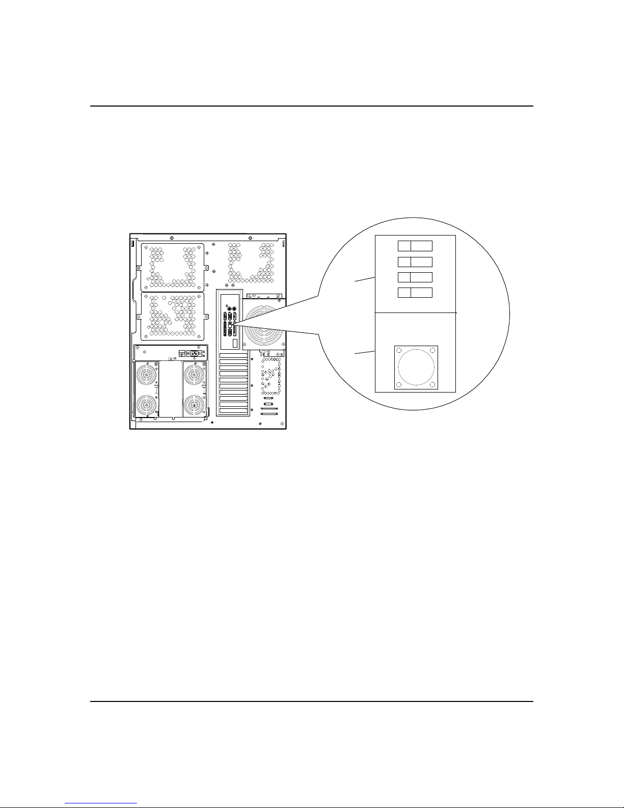
4-25
The function select DIP switches configure the modes of
your server. Figure 4-1 sho ws the DIP switches that
consist of a block of four switches, acce ssible on the I/O
panel that is located on the I/O riser board at the rear
of the chassis.
Figure 4-1. Function Select Switches and Dump Button
A Function select switches
B Dump button
Situations that require changing switch settings include
using an uninterruptible power supply.
Note: The switches are set correctly at the f actory for
your system configuration. If your sy stem requires a
switch change, change only the switch setting f or that
condition. Otherwise keep the switche s at their factory
settings.
A
B
1
2
3
4
ON
Table 4-9 shows the switch configurations and
functions. Set the switches per Table 4- 9 and the
following steps.
Configuring Your System
Page 80
4-26
Table 4-9 Function Select Switch Settings
Switch Signal Settings Function
SW1 RESERVED Off (factory setting)
On
SW2 RSTMASK Off
On (factory setting)
SW3 ACLINK Off (factory setting)
On
SW4 RESERVED Off (factory setting)
On
To change a switch setting, use the follow ing procedure.
Note: Power must be completely of f before setting the
switches, otherwise the settings will not be reco gnized.
1. At the front of the server, press the Power switch
off.
Reserved for future use.
Reserved for future use.
Sets server for use with a local power source.
Sets server for use with an optional
uninterruptible power supply (UPS) unit and
disables the Power button on the front of the
server.
Reserved for future use.
2. At the rear of the server , press the Main Power
switch off.
3. At the rear of the server, locate the Function Select
DIP switch (see Figure 4-1) that you want to change.
4. Set the appropriate sw itch on or off, according to
Table 4-9.
Note: If you set SW3 to On for use with an optional
UPS unit, power the UPS unit u p before switching
power on the server.
5. Press the main Power switch on.
■
If using an UPS unit, the server powers up as
soon as the UPS unit is turned on (the Po wer
button on the front of the server is disabled.)
■
If not using the U PS unit, press the Pow er
button on the front of the server.
Configuring Your System
Page 81

Configuring System Board Jumpers
Before You Begin
Only a qualified technical person shou ld perform the
procedures in this section.
4-27
Notice:
board. Modify the system board only at an ESD workstation.
Otherwise, wear an antistatic wrist strap attached to chassis
ground.
The system board jumpe rs enable you to set spe cific
operating parameters for your sy stem. A jumper is a
small plastic-encased conductor (shorting plug ) that
slips over two jumper pins.
Figure 4-2 shows the location o f the system board
jumpers. Table 4-10 lists the system bo ard jumpers and
their factory default settings.
Electrostatic discharge (ESD) can damage the system
Configuring Your System
Page 82
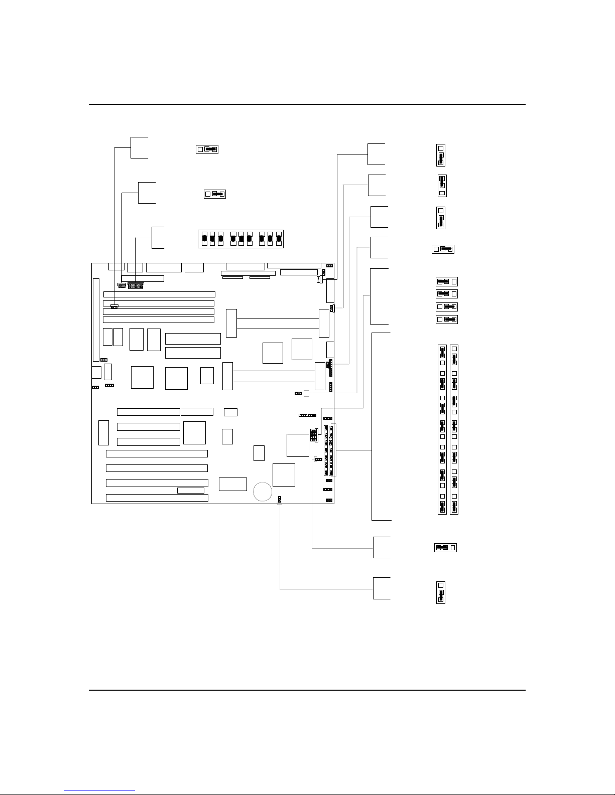
4-28
Figure 4-2. System Board Jumpers
Model Type
Model Type
Reserved
123
123
J54
J53
J21
Model Type
CPU 2
CPU 1
HD Activity
Model Type
Reserved
J7A
FLASH Code
J6A
Reserved
J5A
CPU Speed
J4A
CPU Speed
J3A
CPU Speed
J2A
CPU Speed
J1A J1B
3
2
1
3
2
1
3
2
J49
1
123
123
A
B
3
2
Reserved
1
J7B
Reserved
J6B
CPU Speed
J5B
Model Type
J4B
Reserved
J3B
Password Clear
J2B
3
2
CMOS Clear
1
J51
J50
J612
J27
J26
J25
J29
Configuring Your System
Model Type
Reserved
123
J52
3
J28
2
1
Page 83
Table 4-10. System Board Jumper Configurations
4-29
Jumper Description Option Setting Factory
Reserved
J7A
FLASH Code
J6A
Reserved
J5A
CPU Speed
J4A
CPU Speed
J3A
CPU Speed
J2A
CPU Speed
J1A
Reserved
J7B
Reserved
J6B
CPU Speed
J5B
Model Type
J4B
Reserved
J3B
Password Clear
J2B
CMOS Clear
J1B
Reserved
J21
Model Type
J25
FLASH reprogramming
power protection
Used with jumpers at
J1A, J2A, J3A, J5B and
J5B to set CPU speed
Used with jumpers at
J1A, J2A, J4A, J5B and
J5B to set CPU speed
Used with jumpers at
J1A, J3A, J4A, J5B and
J5B to set CPU speed
Used with jumpers at
J2A, J3A, J4A, J5B and
J5B to set CPU speed
Used with jumpers at
J1A, J2A, J3A and J4A
to set CPU speed
Used with jumpers at
J25, J26, J27, J29, J51,
J52, J53 and J54 to set
server model type
Password protection Password protection enabled
Real-time clock CMOS
protection
All nine jumpers must
be in
Used with jumpers at
J4B, J26, J27, J29, J51,
J52, J53 and J54 to set
server model type
Required on factory default. 2-3 2-3 2-3
BIOS not write protected; FLASH update
BIOS write protected; no FLASH update
Required on factory default. 1-2 1-2 1-2
Refer to Table 4-11 to set CPU speed.
Bus:CP Freq = 1:4 or 2:9 = pins 1-2; Bus:CP
Freq = 1:2, 1:3, 2:5 or 2:7 = pins 2-3
Refer to Table 4-11 to set CPU speed.
Bus:CP Freq = 1:3 or 2:7 = pins 1-2; Bus:CP
Freq = 1:2, 1:4, 2:5 or 2:9 = pins 2-3
Refer to Table 4-11 to set CPU speed.
Bus:CP Freq = 1:2, 1:3, 1:4, 2:5, 2:7 or 2:9 =
pins 2-3
Refer to Table 4-11 to set CPU speed.
Bus:CP Freq = 2:5 2:7, or 2:9 = pins 1-2;
Bus:CP Freq = 1:2, 1:3 or 1:4 = pins 2-3
Required on factory default. 1-2 1-2 1-2
Required on factory default. 1-2 1-2 1-2
Refer to Table 4-11 to set CPU speed.
Bus Freq = 60 MHZ = pins 1-2;
Bus Freq = 66 MHZ = pins 2-3
Required on factory default.
Required on factory default. 1-2 1-2 1-2
Password cleared; protection off
RTC CMOS protection enabled
RTC CMOS cleared to factory defaults
Required on factory default. IN IN IN
Required on factory default.
1-2
2-3
Dependent on
speed of installed
CPU.
Dependent on
speed of installed
CPU.
Dependent on
speed of installed
CPU.
Dependent on
speed of installed
CPU.
Dependent on
speed of installed
CPU.
2-3 2-3 2-3
1-2
2-3
1-2
2-3
2-3 2-3 2-3
Default
1-2
1-2
1-2
Your
Setting
Configuring Your System
Page 84
4-30
Table 4-10. System Board Jumper Configurations (continued)
Jumper Description Option Setting Factory
Model Type
J26
Model Type
J27
Reserved
J28
Model Type
J29
CPU 1
J49
CPU 2
J50
Model Type
J51
Model Type
J52
Model Type
J53
Model Type
J54
HD Activity
J612
Used with jumpers at
J4B, J25, J27, J29, J51,
J52, J53 and J54 to set
server model type
Used with jumpers at
J4B, J25, J26, J29, J51,
J52, J53 and J54 to set
server model type
Used with jumpers at
J4B, J25, J26, J27, J51,
J52, J53 and J54 to set
server model type
CPU 1 installed
CPU 2 installed
Used with jumpers at
J4B, J25, J26, J27, J29,
J52, J53 and J54 to set
server model type
Used with jumpers at
J4B, J25, J26, J27, J29,
J51, J53 and J54 to set
server model type
Used with jumpers at
J4B, J25, J26, J27, J29,
J51, J52 and J54 to set
server model type
Used with jumpers at
J4B, J25, J26, J27, J29,
J51, J52 and J53 to set
server model type
Used to “OR” the two
HD activity signals
Required on factory default. 1-2 1-2 1-2
Required on factory default. 1-2 1-2 1-2
Required on factory default. 1-2 1-2 1-2
Required on factory default. 2-3 2-3 2-3
CPU installed
CPU NOT installed
CPU installed
CPU NOT installed
Required on factory default. 1-2 1-2 1-2
Required on factory default. 1-2 1-2 1-2
Required on factory default.
Required on factory default.
“OR” the two HD activity signals
Separate HD activity signals
1-2
2-3
1-2
2-3
2-3 2-3 2-3
2-3 2-3 2-3
1-2
2-3
Default
1-2 1-2
2-3
2-3
Setting
Your
CPU SPEED Jumper Settings
233/66 MHz 1-2 2-3 1-2 2-3 2-3
266/66 MHz 2-3 2-3 2-3 1-2 2-3
300/66 MHz 1-2 2-3 2-3 1-2 2-3
Configuring Your System
Table 4-11. CPU Speed Jumper Configurations
J1A J2A J3A J4A J5B
Page 85
Table 4-11. CPU Speed Jumper Configurations (continued)
CPU SPEED Jumper Settings
J1A J2A J3A J4A J5B
333/66 MHz 2-3 2-3 1-2 1-2 2-3
Moving System Board Jumpers
Caution: Before doing the procedure s in this section,
!
make sure that your system is powered off and unplug
the AC power cord from the back o f the chassis. Failure
to disconnect power before moving the jumpers can
result in personal injury and equipmen t damage
Notice: Observe static precautions. U se an antistatic
wrist strap.
To configure the system board options:
1. Power off the system and remove the covers as
described in the Upgrades and Options chapter.
4-31
2. Check to ensure the system power cord is removed
from the back of the system.
3. Locate the position of the jumpers on the system
board you are changing. Refer to Figure 4-2.
4. To change a jumper setting, use a pair of needle-nose
pliers or your fingers to remov e the jumper from its
current location. Position the jumper over the two
pins for the desired setting and press it onto the
pins. Be careful not to bend the pins. Ref er to Table
4-10 for system board jumpe r settings.
5. Record changes to the system bo ard jumpers in Table
4-10.
6. Install the system covers and pow er up the system
using procedures in chapter 4 of this guid e.
7. Run the RCU utility to verify your reconfiguration of
the system board.
Configuring Your System
Page 86

4-32
Updating the BIOS
To update the system BIOS:
Note: This procedure clears the event log contents. If
you want to save the event log contents, run the Event
Log Reader Utility.
1. Using the EXPRESSBUILDER CD-ROM, create the
BIOS FLASH diskette.
2. Inse rt a bootable DOS diskette into Driv e A and
power up the system.
3. Inse rt the BIOS FLASH diskette into Drive A.
4. Enter PHLASH and press ENTER.
5. Af ter the system reboots, load the default values by
pressing F2 to enter setup. At the Exit Menu, select
GET DEFAULT VALUES.
6. Cle ar the event log by selecting CLEAR EVENT LOG
at the Server Menu. Press space bar to chang e NO to
YES and press ESC. Sele ct SAVE CHANGES & EXIT
and press ENTER to continue. The syste m will
reboot.
If the procedure fails, perfo rm the following steps and
then retry the Update BIOS procedure.
1. Turn off the system and remove the panels as
2. Ensure the FLASH Co de jumper J6A is set to pins 1-
3. Re place the panel and power up the sy stem with the
Configuring Your System
described in the Upgrades and Options chapter.
2 to enable updates to the BIOS ( see Figure 4-2).
BIOS FLASH diskette inserted in Drive A
Page 87

Resetting the CMOS NVRAM
To reset the CMOS NVRAM:
1. Power off the system and remove the panels as
described in the Upgrades and Options chapter.
2. Move the CMOS Clear jumper J1B to pins 2-3 (see
Figure 4-2).
3. Turn the system on and wait for the POST to
complete. This will automatically reprogram the
CMOS NVRAM to the default settings.
4. Power off the system.
5. Move the CMOS Clear jumper to from pins 2-3 to
pins 1-2.
6. Replace the panels and power on the system.
7. Run the Setup Utility to configure your sy stem.
4-33
Clearing and Changing the Password
To clear and change the password:
1. Power off the system and remove the panels as
described in the Upgrades and Options chapter.
2. Move the Password Clear ju mper J2B to pins 2-3 (see
Figure 4-2).
3. Power on the system and w ait for POST to complete.
This automatically clears the old password .
4. Power off the system.
5. Move the Password Clear ju mper back to pins 1- 2.
6. Replace the panels and power on the system.
7. To spe cify a new password run the Se tup Utility as
described earlier in this chapter.
Configuring Your System
Page 88

4-34
Configuring Your System
Page 89

Chapter 5
Upgrades and Options
Contents
Precautions ............................................................................1
Preparing Your System for Upgrade ..........................................3
Equipment Log ...................................................................3
Removing a Side Panel.......................................................4
Installing a Side Panel ........................................................5
Removing the Top Cover .................................................... 6
Installing the Top Cover......................................................8
Modifying the System Board .....................................................8
Installing Video Memory .....................................................9
Replacing the Non-Volatile Memory................................... 10
Replacing the Real-time Clock Battery ............................... 11
Pentium II Processor........................................................ 13
Installing a Processor .................................................. 13
Removing a Processor ................................................. 15
DIMMs............................................................................. 16
Installing DIMMs .......................................................... 18
Removing DIMMs......................................................... 19
Option Boards....................................................................... 19
Installation Considerations................................................ 20
Controller/Adapter Hardware Configurations ...................... 21
Installing an Option Board ................................................ 23
Removing an Option Board ............................................... 26
Power Supply Module ............................................................ 27
Removing a Power Supply Module ..................................... 27
Installing a Power Supply Module...................................... 28
Installing or Swapping a Disk Drive in a Hot-swap Bay............. 29
Installing or Swapping a Hard Drive ................................... 30
Removable Media Devices and Diskette Drives ....................... 33
Installing a 5 1/4-Inch Device or 3 1/2-Inch Dis kette Drive .. 35
Removing a 5 1/4-Inch Device or 3 1/2-Inch Disk ette Drive . 40
Swapping Out a Fan Module................................................... 43
Page 90

xxxxx
Page 91

Precautions
!
5-1
The following warnings and cautions apply throughout
this chapter. Only a technically qualified perso n should
integrate and configure the system.
The only procedure that can safely be done with the
system power on is installing ( or hot-swapping) an SCA
drive/carrier assembly in one o f the SCSI hot-swap
drive bays or hot-swapping a faile d fan module or power
supply. For any other procedures inside the system,
turn off system power and disconnect the AC power
cord(s).
Warning: Before doing the procedures in this chapte r,
make sure that your system is powered off and unplug
the AC power cord from the back o f the chassis. Failure
to disconnect power before opening your system can
result in personal injury and equipmen t damage
Warning:
on/off switch (a convex button) on the front panel DOES
NOT turn off the system AC power. To remove power
from system, you must unplug the AC power cord(s)
(from wall outlet or po wer supply).
Warning: Hazardous conditions, power supply.
Hazardous voltage, current, and energy levels are
present inside the power supply. There are no user
serviceable parts inside it; servicing sho uld be done by
technically qualified personnel.
Warning: Hazardous conditions, devices & cables.
Hazardous electrical conditions may be presen t on
power, telephone, and co mmunication cables. Turn off
the system and disconnect the power cords,
telecommunica tions systems, netwo rks, and modems
attached to the system before opening it. Otherwise,
personal injury or equipment damage can result.
System power on/off.
The DC push-button
Upgrades and Options
Page 92

5-2
Caution: Ele ctrostatic discharge (ESD) and ESD
!
protection. ESD can damage disk drives, boards, and
other parts. This system can withstand normal levels of
environmental ESD while you are hot-swapping SCSI
hard drives or hot-swapping a faile d fan module or
power supply. However, we recommend that you do all
procedures in this chapter only at an ESD wo rkstation.
If one is not available, prov ide some ESD protection by
wearing an antistatic wrist strap attached to chassis
groundany unpainted metal surfaceon your system
when handling parts
Caution: ESD and handling boards. Always handle
boards carefully. They can be extre mely sensitive to
ESD. Hold boards only by their edge s. After removing a
board from its protective wrapper or from the system,
place it component-side up o n a grounded, static-free
surface. Use a conductive foam pad if av ailable but not
the board wrapper. Do not slide board over any surface.
Caution: Chassis covers, proper cooling and
airflow. For proper cooling and airflow , always install
the chassis side and top covers before turning on the
system. Operating it without the se covers in place can
damage system parts.
Contact your sales representative or dealer for a list of
approved optional peripheral devices.
Upgrades and Options
Page 93

Preparing Your System for Upgrade
Depending on the upgrade, you w ill need one or more of
the following tools:
■ Phillips screwdriver (#1 bit and #2 bit)
■ Flat-head screwdriver
■ Small needle nose pliers
■ Pen or pencil
■ Utility knife
■ ESD workstation or antistatic wrist strap
(recommended)
■ IC removal tool.
Equipment Log
5-3
Use the equipment log form located at the end of this
manual to record the model and serial number of yo ur
system, all installed options, and any other pertinent
information specific to your sy stem. You will need this
information when configuring your system.
Upgrades and Options
Page 94

5-4
Removing a Side Panel
To install boards in your system, you must remove the
external side panel.
Caution: For proper cooling and airflow, do not operate
!
the system with the side panels removed. Always
replace the panels before po wering on the system
Caution: Do not damage or bend the EMI fingers that
are located along the top o f the chassis on its two sides,
as you remove and install the side panels, o r your
system may not meet EMI requirements.
Warning: If you are removing the side panel after the
system is set up, you must first power o ff the system
and all external devices. Unplug the syste m power
cord.
Warning: If you are attempt to rem ove the side pane l
with the system power on, the power interlock will
power off the system.
To remove a side panel:
1. Po wer off the system and e nsure it is disconnected
from the ac wall outlet.
2. O bserve the safety and ESD pre cautions listed at
the beginning of this chapter.
3. The side panel is secured from the back edge with
two screws. Remove the padlock (if used) and the
screws (Figure 5-1) securing the side panel. Sav e the
screws for reattaching the side panel.
4. G rip the built-in handle on the back of the pane l.
Slide the side panel toward the rear o f the chassis
about an inch until it stops.
5. Pull the side panel out and away fro m the chassis.
Set the panel aside.
Upgrades and Options
Page 95
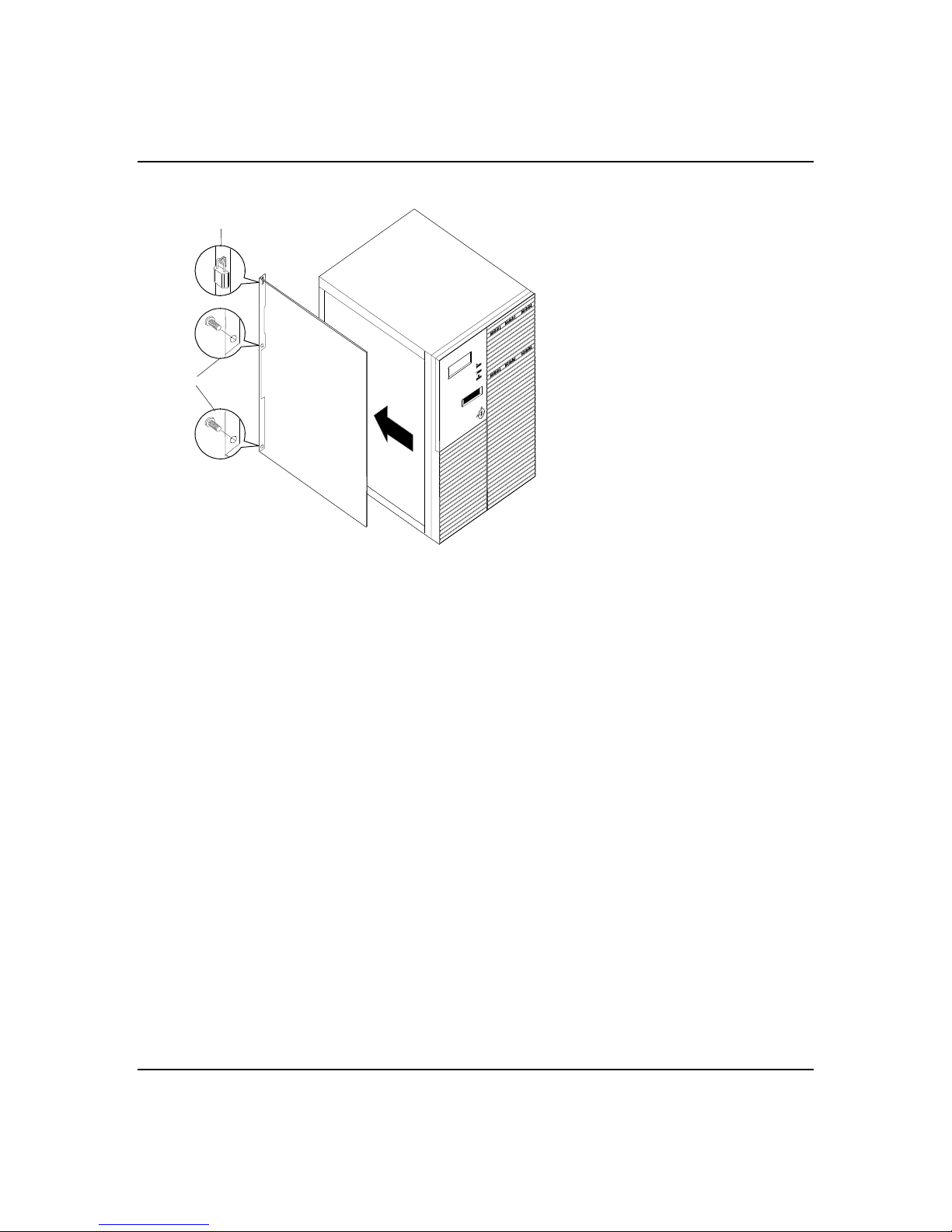
Figure 5-1. System Side Panel
5-5
A
B
Installing a Side Panel
1. Befo re replacing the side panel, make sure no to ols
System side panel
A Padlock at back edge (if installed)
B Retaining screws (two at back)
External side panel over the board
area is shown; procedure is the same
for both side panels.
POWER
STATUS
DISK
or loose parts have been left inside the system
chassis.
2. Make sure all o ption boards are firmly seated in
their respective slots and that all interio r cables are
properly connected.
3. Orient the cover so the padlock slot at the back edge
fits over the loop at the back edge of the chassis (see
Figure 5-1).
4. Align the top and bottom rows of tabs on the cover
with the slots in the chassis, and carefully push
inward.
5. Slide the cover toward the front so the tabs firmly
engage in the slots. If the cover does not slide freely
all the way forward, make sure the padlo ck slot is
correctly placed over the loop on the chassis back.
6. Attach the cover to the chassis with the two screws
you removed earlier, and tighten firmly.
Upgrades and Options
Page 96

5-6
7. To preven t unauthorized ac cess inside the syste m,
insert and lock a padlock through the loop at the
back (one at each side).
Note: If your system is already se t up, plug the system
back in, reconnect the peripherals, and po wer on the
peripherals and system .
Removing the Top Cover
Note: The top cover does not have to be removed in
order to install any upgrades o r options.
You must remove both side covers be fore you can
remove the top cover.
Caution: For proper cooling and airflow, do not operate
!
the system with the top cover removed. Always replace
the cover before powering on the system
Caution: Do not damage or bend the EMI fingers
located on the bottom of the co ver as you remove and
install it, or your system may not mee t EMI
requirements.
Warning: If you are removing the top cover after the
system is set up, you must first power o ff the system
and all external devices. Unplug the syste m power
cord.
To remove the top cover:
1. Po wer off the system and e nsure it is disconnected
from the ac wall outlet.
2. O bserve the safety and ESD pre cautions listed at
the beginning of this chapter.
3. Re move both side panels.
Upgrades and Options
Page 97
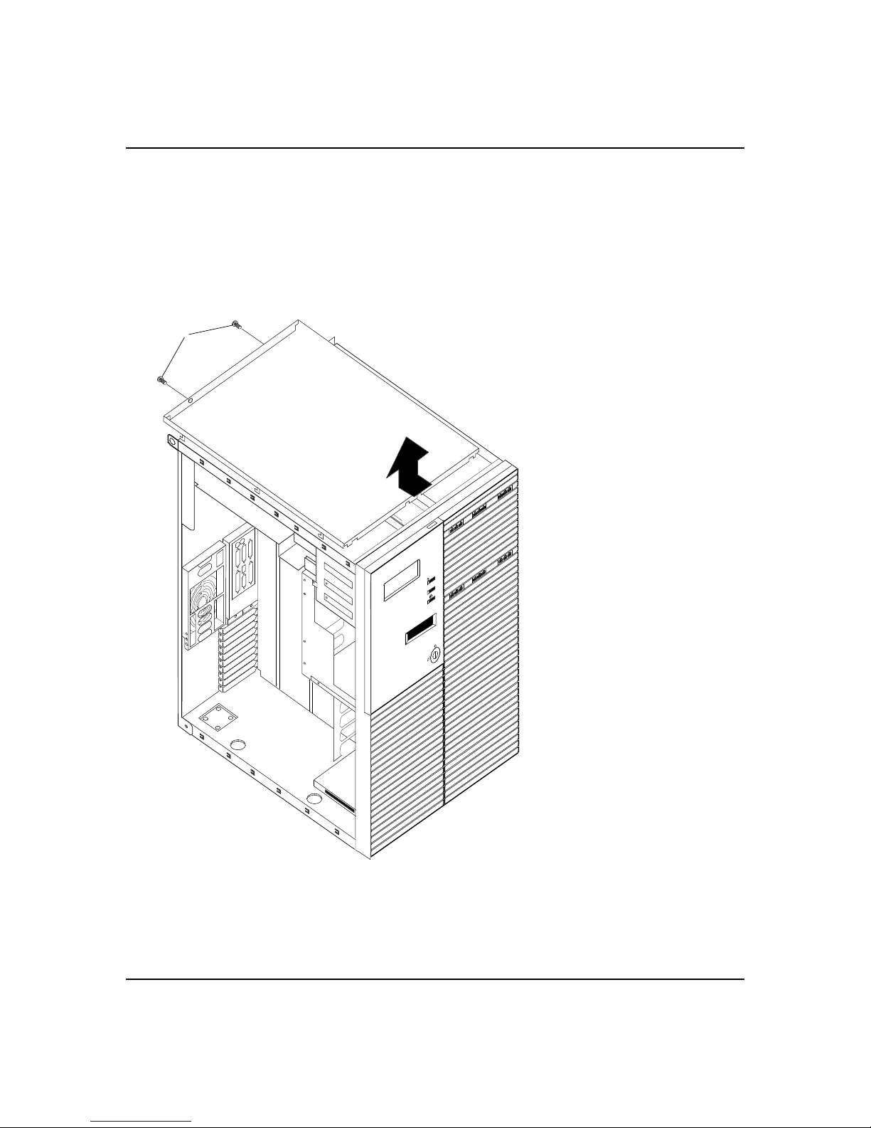
5-7
4. At the back, remove two retaining screws from the
top cover (see Figure 5-2).
5. Av oid bending the EMI fingers as you slide the cover
back very slightly (to about a 1/2-inch or le ss.) Then
pick the cover straight up from the chassis.
Figure 5-2. System Top Cover
A
Removing top cover
A Retaining screws (two at back)
To avoid damaging EMI fingers,
do not slide the cover back much
more than the 1/2-inch implied
here.
Upgrades and Options
Page 98

5-8
Installing the Top Cover
1. Be fore replacing the top cover, make sure no tools or
loose parts have be en left inside th e system chassis.
2. Make sure all option boards are firmly seate d in
their respective slots and that all interio r cables are
properly connected.
3. Lower the cover straight down with the front edge
about 1/2 inch back from the edge of the plastic
bezel (front cover). The sid es of the cover should be
outside the chassis metal.
4. Care fully slide the front edge of the cover forward
until it stops at the edge of the f ront bezels.
5. Re install two retaining screws at the back.
6. Re install the two side panels.
Modifying the System Board
The following sections provid e procedures for upgrading
and configuring the system board in yo ur system. Topics
covered include:
■ Installing video memory DRAMs
■ Replacing the Non-Volatile Memory
■ Replacing the real-time clock battery
■ Installing or removing a processor
■ Installing or removing DIMMs.
Notice:
in boards and other components; place the m on an
antistatic surface. Modify the system bo ard only at an
ESD workstation. Otherwise, wear an antistatic w rist
strap attached to chassis g round.
Electrostatic discharge (ESD) can damage add-
Upgrades and Options
Page 99
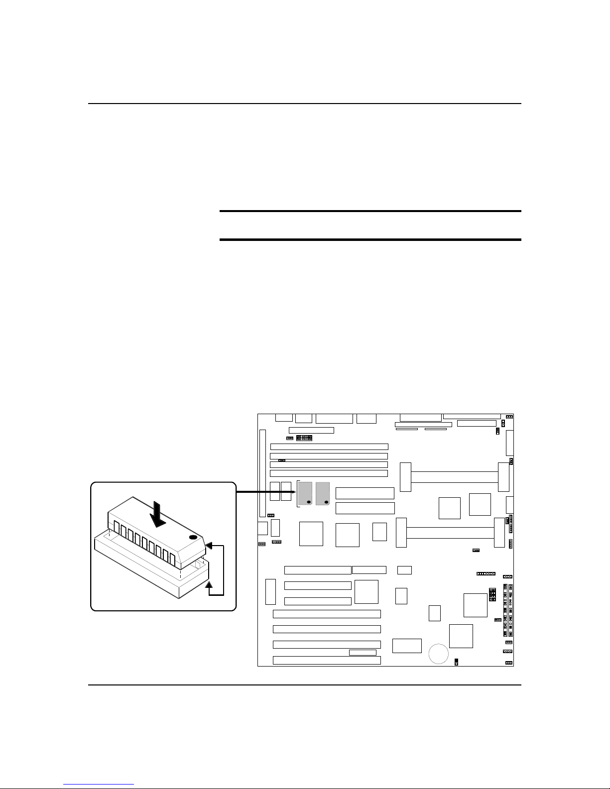
Installing Video Memory
The base system includes two 512K video memory
DRAM chips and two sockets on the sy stem board. If
you add two additional 512K vide o memory DRAMs into
the sockets shown in Figure 5-3, the base video memory
size is increased from 1 MB to 2 MB.
Notice: Observe static precautions. U se an antistatic
wrist strap.
1. Power off the system and remove the side panel as
described earlier in this chapter.
2. Align the be veled edge of the DRAMs w ith the
notched corner of the DRAM sockets. Refer to Figure
5-3 for the DRAM socket locations.
3. Press the D RAMs down firmly until they are fully
seated in their sockets.
4. Replace the side panel and power on the sy stem.
5-9
Figure 5-3. Video Memory DRAM Location
Upgrades and Options
Page 100
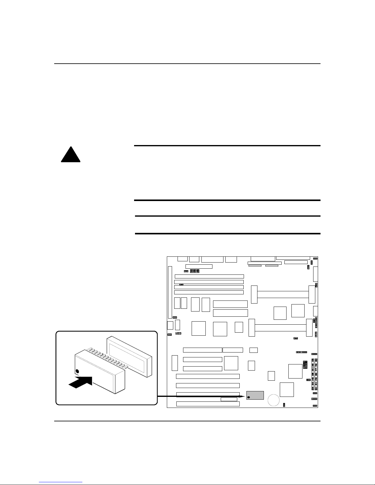
5-10
Replacing the Non-Volatile Memory
You may need to replace the non-volatile memory
because of its internal integral lithium battery lif e
span. Contact your sales representativ e or dealer for a
list of approved devices. Its located on your system
board as shown in Figure 5-4. Notice the d ot on the
chip. This dot will assist you in correctly po sitioning the
chip on the system board.
Caution: Danger of explosion if battery is incorre ctly
!
replaced. Replace only with same o r equivalent type
recommended by manufacturer. Dispose of lithium
batteries as required by local ordinance or as no rmal
waste if no local ordinance ex ists. Do not expose the
component to excessiv e heat or fire. Keep all batte ries
away from children
Notice: O bserve static precautions. Use an antistatic
wrist strap.
Figure 5-4. Non-Volatile Memory Location
Upgrades and Options
 Loading...