

Page 1

SERVER MH4500
()
■■■■■■■
■■■■■■■
■■■■■■■
■■■■■■■
■■■■■■■
■■■■■■■
User's Guide
■■■■■■■
■■■■■■■
■■■■■■■
■■■■■■■
■■■■■■■
■■■■■■■
■■■■■■■
■■■■■■■
Page 2

xxx
Page 3

SERVER MH4500
()
■■■■■■■
■■■■■■■
■■■■■■■
■■■■■■■
■■■■■■■
■■■■■■■
User's Guide
■■■■■■■
■■■■■■■
■■■■■■■
■■■■■■■
■■■■■■■
■■■■■■■
■■■■■■■
■■■■■■■
Page 4

Proprietary Notice and Liability Disclaimer
The information disclosed in this document, including all designs and related materials, is
the valuable property of NEC Computers Inc. and/or its licensors. NEC Computers Inc.
and/or its licensors, as appropriate, reserve all patent, copyright and other proprietary rights
to this document, including all design, manufacturing, reproduction, use, and sales rights
thereto, except to the extent said rights are expressly granted to others.
The NEC Computers Inc. product(s) discussed in this document are warranted in
accordance with the terms of the Warranty Statement accompanying each product.
However, actual performance of each such product is dependent upon factors such as
system configuration, customer data, and operator control. Since implementation by
customers of each product may vary, the suitability of specific product configurations and
applications must be determined by the customer and is not warranted by NEC Computers
Inc.
To allow for design and specification improvements, the information in this document is
subject to change at any time, without notice. Reproduction of this document or portions
thereof without prior written approval of NEC Computers Inc. is prohibited.
Trademarks
Intel is a registered trademark of Intel Corporation.
MS-DOS is a registered trademark of Microsoft Corporation.
Pentium is a registered trademark of Intel Corporation.
All other trademarks belong to their respective owners.
PN: 456-00008-003
Copyright 1998, 1999, 2000
NEC Computers Inc.
15 Business Park Way
Sacramento, CA 95828
All Rights Reserved
NEC
Page 5

Contents
Proprietary Notice and Liability Disclaimer.....................................................................vii
Using This Guide........................................................................................................... viii
Text Conventions .............................................................................................................ix
Related Documents............................................................................................................x
Safety Notices..................................................................................................................xi
Safety Notices for Users Outside of the U.S.A. and Canada........................................xii
Care and Handling......................................................................................................... xiii
System Overview................................................................1-1
System Chassis Features................................................................................................ 1-3
Power Supplies......................................................................................................... 1-4
System Cooling........................................................................................................ 1-4
Peripheral Bays ........................................................................................................ 1-5
System Board Features.................................................................................................. 1-5
Pentium II Xeon Processor ....................................................................................... 1-7
System Memory ....................................................................................................... 1-7
I/O Expansion Slots.................................................................................................. 1-7
Real-Time Clock/Calendar....................................................................................... 1-8
BIOS........................................................................................................................ 1-8
IDE Controller.......................................................................................................... 1-8
SCSI Controllers ...................................................................................................... 1-9
Video Controller..................................................................................................... 1-10
Peripheral Controller.............................................................................................. 1-10
External Device Connectors.................................................................................... 1-11
System Board Management Controller (BMC)........................................................ 1-11
System Security Features............................................................................................. 1-11
Mechanical Locks and Monitoring.......................................................................... 1-11
Software Locks....................................................................................................... 1-11
Setting Up Your System .................................................... 2-1
Selecting a Site.............................................................................................................. 2-2
Unpacking the System................................................................................................... 2-3
Getting Familiar with the System................................................................................... 2-4
Installing the System......................................................................................................2-7
Connecting Peripherals.................................................................................................. 2-7
Connecting the Power Cords.......................................................................................... 2-7
Powering On the System................................................................................................ 2-8
Converting to a Rack Mount Server Unit..................................................................... 2-10
Equipment Rack Warnings and Cautions................................................................ 2-11
Converting the System Pedestal Unit...................................................................... 2-12
Preparing the Rack................................................................................................. 2-18
Installing the Rack Unit in the Rack........................................................................ 2-21
Contents iii
Page 6

Configuring Your System...................................................3-1
Using the BIOS Setup Utility......................................................................................... 3-3
Main Menu............................................................................................................... 3-4
Advanced Menu....................................................................................................... 3-6
Security Menu........................................................................................................ 3-10
Server Menu........................................................................................................... 3-12
Boot Menu............................................................................................................. 3-14
Exit Menu.............................................................................................................. 3-16
Using the Symbios SCSI Utility................................................................................... 3-16
Running the Symbios SCSI Utility.......................................................................... 3-16
Changing the Adapter and Device Configurations................................................... 3-17
Using the Optional RAID Controller............................................................................ 3-20
Factory Installed Controller .................................................................................... 3-20
Add-on Controller.................................................................................................. 3-20
DACCF Configuration Utility................................................................................. 3-21
Configuring System Board Jumpers............................................................................. 3-22
Moving System Board Jumpers.............................................................................. 3-23
Resetting the CMOS NVRAM................................................................................ 3-24
Clearing and Changing Passwords.......................................................................... 3-24
Upgrading Your System.....................................................4-1
Observing Static Precautions......................................................................................... 4-2
Preparing Your System for Upgrade.............................................................................. 4-3
Preparing the Equipment Log........................................................................................ 4-3
Removing the Access Cover.......................................................................................... 4-4
Installing the Access Cover.......................................................................................4-5
Opening the Subchassis and Electronics Bay.................................................................. 4-6
Closing the Subchassis and Electronics Bay.............................................................. 4-7
Upgrading the System Board......................................................................................... 4-8
Replacing the Real-time Clock Battery..................................................................... 4-8
Installing/Removing the Processor Cartridge........................................................... 4-10
Installing DIMM Modules...................................................................................... 4-14
Installing Option Boards.............................................................................................. 4-19
Installation Considerations...................................................................................... 4-20
Controller/Adapter Hardware Configurations.......................................................... 4-21
Installing an Option Board...................................................................................... 4-21
Removing an Option Board.................................................................................... 4-22
Installing Hard Disk Drives......................................................................................... 4-24
Installing an Optional SCSI Hard Disk Drive.......................................................... 4-25
Hot-Swapping a SCSI Hard Disk Drive.................................................................. 4-26
Installing Removable Media Devices........................................................................... 4-27
Installing a 5 1/4-Inch Media Device...................................................................... 4-28
Removing a 5 1/4-Inch Media Device..................................................................... 4-30
Solving Problems................................................................5-1
Static Precautions.......................................................................................................... 5-2
Troubleshooting Checklists............................................................................................ 5-2
Initial System Startup............................................................................................... 5-3
Running New Application Software.......................................................................... 5-4
After System Has Been Running Correctly............................................................... 5-4
iv Contents
Page 7

Additional Troubleshooting Procedures......................................................................... 5-5
Preparing the System for Diagnostic Testing.............................................................5-5
Monitoring POST..................................................................................................... 5-6
Verifying Proper Operation of Key System Indicators...............................................5-7
Confirming Loading of the Operating System ........................................................... 5-7
Specific Problems and Corrective Actions ..................................................................... 5-7
Power LED Does Not Light...................................................................................... 5-8
No Beep Code.......................................................................................................... 5-8
No Characters Appear on Screen .............................................................................. 5-8
Characters are Distorted or Incorrect......................................................................... 5-9
System Cooling Fan(s) Does Not Rotate................................................................... 5-9
Diskette Drive Activity LED Does Not Light.......................................................... 5-10
Hard Disk Drive Activity LED Does Not Light....................................................... 5-10
CD ROM Drive Activity Light Does Not Light....................................................... 5-11
Problems with Application Software....................................................................... 5-11
Press F2 Key to Enter Setup: Prompt Does Not Display.......................................... 5-11
Bootable CD-ROM Is Not Detected........................................................................ 5-13
Problems with the Network..................................................................................... 5-14
PCI Installation Tips.................................................................................................... 5-14
BIOS User’s Information............................................................................................. 5-15
Error and Status Messages...................................................................................... 5-15
Messages and Beep Codes...................................................................................... 5-17
POST Error Codes and Messages............................................................................ 5-21
System Cabling..................................................................A-1
Before You Begin..........................................................................................................A-2
Static Precautions..........................................................................................................A-2
Standard Configuration..................................................................................................A-2
Power Cabling..........................................................................................................A-3
Diskette Drive Data Cabling.....................................................................................A-3
SCSI Cabling............................................................................................................A-3
RAID Configuration......................................................................................................A-5
System Setup Utility...........................................................B-1
Creating SSU Diskettes.................................................................................................B-3
Running the SSU...........................................................................................................B-3
Customizing the SSU................................................................................................B-4
Launching a Task.....................................................................................................B-5
Resource Configuration Add-in (RCA) Window.......................................................B-6
Defining an ISA Board.............................................................................................B-7
Adding and Removing ISA Boards...........................................................................B-8
Modifying Resources................................................................................................B-8
Recommended Resource Settings.............................................................................B-9
System Resource Usage..........................................................................................B-11
Multiboot Add-in (MBA) Window.........................................................................B-11
Password Administration (PWA) Window..............................................................B-12
System Event Log (SEL) Window ..........................................................................B-12
Sensor Data Record (SDR) Manager Add-In Window............................................. B-13
Field Replaceable Unit (FRU) Manager Add-In Window ........................................B-14
Exiting the SSU...........................................................................................................B-14
Contents v
Page 8

Emergency Management Port...........................................C-1
How the EMP Works.....................................................................................................C-2
EMP Requirements and Configurations .........................................................................C-5
Setting Up the Server for the EMP.................................................................................C-6
System Management Submenu.................................................................................C-6
Console Redirection Submenu..................................................................................C-6
Main EMP Window.......................................................................................................C-7
Toolbar .................................................................................................................... C-7
Status Bar.................................................................................................................C-7
EMP Console Main Menu ........................................................................................C-8
Server Control Operations ........................................................................................C-8
Phonebook...................................................................................................................C-12
Management Plug-ins ..................................................................................................C-13
SEL Viewer............................................................................................................C-13
SDR Viewer...........................................................................................................C-14
FRU Viewer...........................................................................................................C-15
FRU and SDR Load Utility..........................................................................................C-16
When to Run the FRUSDR Load Utility................................................................. C-16
What You Need to Do............................................................................................ C-17
How You Use the FRUSDR Load Utility................................................................C-17
Cleaning Up and Exiting.........................................................................................C-21
Glossary
Equipment Log
vi C ont ents
Page 9

System Overview
Syst em Ch assis F eatures
System Board Features
System Security Features
1
Page 10
The MH4500 System is a modular, multiprocessing server based on the
Intel Pentium® II Xeon™ microprocessor. The combination of compute
performance, memory capacity, and integrated input/o ut put (I/O) provides a
high performance environment for many server market applications. These
range from large corporations supporting remote offices to small companies
looking to obtain basic connectivity capability such as file and print services,
email, web access, and web site server.
As application requirements increase, you can expand your server with
additional processors, memory, add-in boards, and peripheral devices (such as
tape devices and hard disk drives).
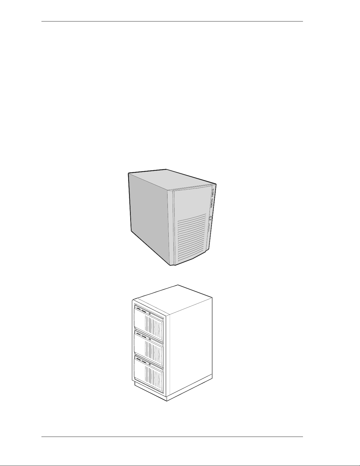
The server is available in two configurations: a stand-alone pedest al system and
a rack system. The pedesta l syste m can be converted to a rack-mounted system
using an optional rack mount kit. Both configurations use the same components
(except there is no outer covers on the rack unit). The following figures show
the pedestal system and a rack system mounted in a rack.
Rack Mounted Server System (three servers shown)
1-2 System Overview
Stand-A lon e Pedestal Server Sys t em
Page 11

Your server features the following major components:
up to four high-performance Pentium II Xeon pro cessors, each packaged
in a Single Edge Connector (S.E.C.) cartridge
integrated 512 KB or 1 MB secondary cache integrated in the S.E.C.
cartridge
128 MB to 4 GB of memory, using up to sixteen dual-inline memory
modules (DIMMs)
six PCI expansion slots for add-in boards (one slot shared with an ISA
slot; one slot for half-length PCI boards).
one half-length ISA expansion slot for add-in boards (shared with a PCI
slot)
onboard Cirrus Logic CL-GD5480 Super Video Graphics Array (SVGA)
controller
2 MB of video DRAM memory
onboard s ingle channel enhanc ed I DE cont r oller
onboard Symbio s SYM53C 810AE sing le channel na rrow S C SI contr oller
on the PCI-A bus providing a narrow SCSI interface for 5 1/4-inch
devices
onboard Symbios SYM53C896 dual-channel wide SCSI controller on the
PCI-B bus providing an ultra 2 wide SCSI interface for 3 1/2-inch
devices
1.44MB diskette drive
SCSI CD-ROM drive
six S C SI hot s wap ha rd disk d rive expansio n bays
SCSI single connecto r att achment ( S CA) compatible backplane that
provides continuous fast/w ide ultra 2 S CS I bus for access t o all ho t-swap
drive ba ys
three 5 1/4-inch bays for removable media devices
PS/2-compatible mouse and keyboard ports
VGA video port
one Universal Serial Bus (USB) port.
System Chassis Features
The system chassis is an easy-to-expand, fabricated metal struct ure housing the
power supplies, fans, expansion bays, system board, and supporting
components. A key feature o f the chassis is t he “swing-out” electronics bay and
subchassis modu les, allowing easy access to t he interior of the system.
System Overview 1-3
Page 12
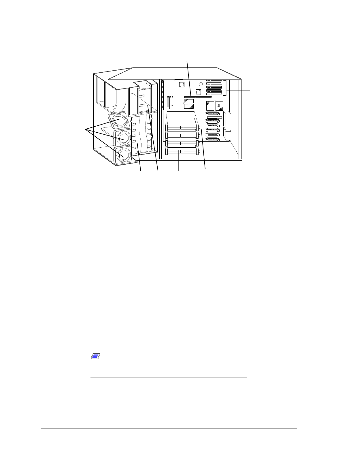
Several major syste m co mponent locations are shown in the fo llowing figure
and briefly described in the following paragraphs.
G
F
A
BC D E
A. Fans (8) E. System Board
B. SCSI Backplane F. Expansion Board Connectors
C. Removable Media Device Bays (3) G. Memory Module Connector
D. S.E.C. Processor Bays (4)
Power Supplies
Two 400 watt auto-voltage-sensing power supplies provide system power. Each
operates at 115 or 230 Vac at an operating frequency of 50/60 Hz. Both supplies
are designed to operate together during system operation. Both power supplies
comply w ith ex is ting emis sions standards and pro vid e s uff icie nt power for a
fully loaded system configuration. An optional third power supply can be added
to the system as a backup unit.
System Cooling
The chassis houses eight fans for cooling and airflow.
the chassis access cov er m ust be installed whenever the
system is running.
Note:
System Chassi s
To maintain proper system cooling and air flow,
1-4 System Overview
Page 13

Peripher al B ay s
The system supports a variety of standard PC AT-compatible peripheral devices.
The chassis includes the following peripheral bays:
3 1/2-inch front panel bay for mounting the standard 3 1/2-inch diskette
drive (supports 720 KB and 1.44 MB diskettes)
three 5 /14-inch removable media device front panel bays for mounting
one inch high 5 1/4-inch peripheral devices, including the standard SCSI
CD ROM drive.
Note:
recommended due t o cooli ng r estr aints and EMI
requirements.
six internal hard disk drive bays for mounting up to six, one inch high,
M
ounting a hard drive in the 5 1/4-inch bay is not
SCSI hot-swap hard disk drives.
System Board Features
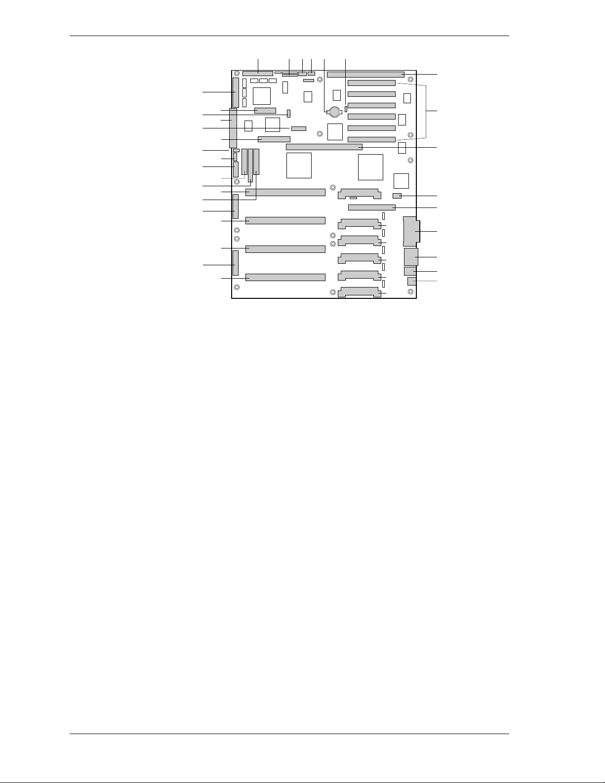
The system board features processor and memory subsystems residing on the
board. The following figure shows the components on the system board. Brief
descriptions of the major components follow the figure.
System Overview 1-5
Page 14
MM
CDA E FB
G
LL
KK
JJ
II
HH
GG
FF
EE
DD
CC
AA
BB
P
Z
Y
X
W
V
Q
R
S
T
U
A. Wide SCSI B Connector U. VRM Connector for Processor 1
B. System Jumpers V. Processor 1, Slot 2 Connector
C. Hard Drive Input LED Connector W. Main Power Connector
D. System Speaker Connector X. Processor 2, Slot 2 Connector
H
I
J
K
L
M
N
O
E. Lithium Battery Y. Processor 3, Slot 2 Connector
F. Wake-on LAN Connector Z. Main Power Connector
G. ISA Slot AA. Front Panel Connector
H. PCI Slots B4, B3, B2, B1, A3, A2 BB. Processor 4, Slot 2 Connector
I. Memory Module Connector CC. IDE Connector
J. ICMB Connector DD. Diskette Drive Connector
K. PCI Slot A1 EE. Au xiliary Power Connector
L. Video and Parallel Port Connectors FF. USB Internal Header
M. Serial Port Connector GG. SMBus Connector
N. Keyboard and Mouse Connector HH. F16 Expansion Connector
O. USB Connector II. ITP Connector
P. VRM Connector for Processor 4 JJ. Narr ow SCSI Connector
Q. VRM Connector for Processors 4 and 3 KK. External IPMB Connector
R. VRM Connector for Processor 3 LL SMM Connector
S. VRM Connector for Processor 2 MM. Wide SCSI A Connector
T. VRM Connector for Processors 2 and 1
1-6 System Overview
System Board
Page 15

Pentium II Xeon Processor
The system board support s up to four Pentium II Xeon processo r s, each
packaged in a Single Edge Contact (S.E.C.) cartr idge. The cartr idge includes t he
processo r core with an integrated 16 KB primary (L1) cache; the secondary (L2)
cache; a thermal plate; and a back cover. T he processor implements the MMX™
technolog y and the processor’s numeric coprocessor signific antly increases the
speed of floating-point operations.
The processo r exter nal inter face operates at 100 MHz. The second-level cache is
located on the substrat e of the S.E. C. cart r idge. The cache inc ludes burst
pipelined synchronous st at ic RAM (BSRAM). T he L2 cache is offered in 512
KB and 1 MB configurations, with error correcting code (ECC) that operates at
half the core clock rate.
The processors are supported by one or more voltage regulator modules (VRM)
on the system board, with the number of VRMs dependent on t he number of
processors installed.
Each S.E.C cartridge connects to the system board through a 330-pin Slot 2
edge connector. The Slot 2 connectors are arranged in a vertical stack o f four on
the system board. The VRM modu les are located adjacent to the processors.
System Memory
S ystem m emory is mounted on a memory module that connects to t he system
board. The module contains sixteen 168-pin DIMM sockets arranged in four
banks. Up to 4 GB of EDO DIMM memory is supported, with 32 MB being the
minimum (the system ships with a minimum of 128 MB). The memory module
supports a 64/72 bit four-way-interleaved pathway to main memory on the
module and supports 4:1 interleaving.
System memory begins at address 0 and is continuous (flat addressing) up to the
maximum amount of DRA M installed (excep tion: s ys te m memory is
noncontiguous in the ranges defined as memory holes using configuration
registers). The system supports both base (conventional) and extended memory.
The system BIOS automatically detects, sizes, and initialize s the memory array,
depending on the type, size, and speed of the insta lled DIMMs. The BIOS
reports memory size and allocat ion to t he syst em via configuration register s.
The memory module connects to the system board through a 242-pin connector.
I/O Expansion Slots
The server's expansio n capab il it ies meet t he needs o f file and application servers
for high performance I/O by providing a combination of PCI local bus and ISA
connectors.
The system boar d has o ne full- le ngt h IS A bus connector. The co nnector shares a
chassis expansion slot with a PCI connector and supports half-length ISA
boards.
System Overview 1-7
Page 16

ISA features include:
bus speed up to 8.33 MHz
16-bit memory addressing
Type A transfers at 5.33 MB/seco nd
Type B transfers at 8 MB/ second
8- or 16-bit data transfers
Plug and Play ready.
The system board has two 32-bit PCI bus segments: PCI-A and PCI-B. The
segments provide seven PCI connectors, three on PCI-A and four on PCI-B.
PCI-A supports half-length boards only and PCI-B supports full-length boards.
One of the PCI-B connectors shares a chassis expansion slot with an ISA
connector.
PCI features include:
bus speed up to 33 MHz
32-bit memory addressing
5 V signaling environment
burst transfers of up to 133 Mbps
8-, 16-, or 32-bit data transfers
Plug and Play ready
parity enabled.
Real-Time Clock/Calendar
The real-time clock provides syste m clock/calendar information stored in a nonvolatile memory (NVRAM). The replaceable real-time clock battery provides
power backup for the real-time clock.
BIOS
A BIOS and Setup Utility are located in the Flash EP ROM on the system board
and include support for system setup and PCI/ISA Plug-and-Play autoconfiguration. A number of security, re liabilit y, and manageme nt featur es also
have been incorpor at ed to meet vita l server needs.
IDE Controller
The system includes a single channel enhanced IDE interface controller. The
controller has a primary co nnect or locat ed o n the system boar d that suppo rts a
master and a slave device.
1-8 System Overview
Page 17

The IDE controller featur es:
PIO and IDE DMA/bus master operations
Mod e 4 timings
transfer rates up to 22 MB/second
buffering for PCI/IDE burst transfers
master/slave I DE mo de.
SCSI Controllers
The system board contains two SCSI controllers: a narrow SCSI controller
(SYM53C810AE) on the PCI-A bus, and a dual-channel wide LVD/SE
(Ultra2/Ultra) SCSI controller (SYM53C896) on the PCI-B bus. The narrow
controller provides support for legacy 8-bit SCSI devices in the 5 1/4-inch drive
bays, including the factory inst alled SCSI CD-ROM dr ive . The wide c ontrolle r
drives one SCSI backplane and provides support for external expansion.
Internally, each wide channel is ident ical, capa ble o f operat ions using either
8- or 16-bit SCSI providing 10 MB/sec (Fast-10) or 20 MB/sec (Fast-20)
throughput, or 20 MB/sec (Ultra), 40 MB/sec (Ultra-wide) or 80 MB/sec
(40 MHz) (Ultra-2).
The SYM53C810AE (narrow) contains a high-performance SCSI cor e capable
of Fast 8-bit SCSI transfers in single-ended mode. It provides programmable
active negation, PCI zero wait-state bursts of faster than 110 MB/sec at 33 MHz,
and SCSI transfer rat es fro m 5 to 10 MB/sec. The narrow SCSI comes in a
100-pin rectangular plastic quad flat pack (PQFP).
The Sym53C896 (wide) contains a high-performance SCSI bus interface. It
supports SE mode with 8-bit (10 or 20 MB/sec) or 16-bit (20 or 40 MB/sec)
transfers and LVD mode with 8-bit (40 MB/sec) or 16-bit (80 MB/sec) transfers
in a 329-pin ball grid array (BGA) package.
Each controller has its own set of PCI configurat ion registers and SCSI I / O
registers. As a PCI 2.1 bus master, the SYM53C896 supports burst data
transfers on PCI up to the maximum rate of 132 MB/second using on-chip
buffers.
In the hot-swap bay, the system supports up to six, one-inch high SCSI hard disk
drives. Also, in the 5 1/4-inch bays, the system supports three SCSI or IDE
devices (the SCSI controller itself supports more devices, but the 5 1/4-inch bay
can only hold a maximum of three devices).
A wide SCSI cable provides two connecto r s for Ultra SCSI devices, one of
which is used for the SCSI backplane. However, S CSI devices do not need to
operate at the ultra transfer r ate. All drives on the bus must be Ultra-2 ( LVD) to
run at 80 MB/sec (40 MHz). The 5, 10, and 20 MHz operations can coexist on
the bus and each device interact s at its appro pr iate speed.
System Overview 1-9
Page 18

No logic, termination, or resistor loads are required to co nnect devices to the
SCSI controller other than terminat ion in the device at the end of the cable. The
SCSI bus is terminated o n t he system boar d with active terminators that can be
disabled.
Video Controller
The system has an onboard integrated Cirrus Logic CL-GD5480 64-bit highperformance SVGA subsystem that supports the following:
BIOS compatibility with VGA, EGA, CGA, Hercules Graphics, and
MDA
2 MB of 10 ns video random access memory (VRAM) video buffer
16-bit bus for high-speed displa y memor y access
hardware accelerated bit block transfers ( BITBLT)
display power management system
supports 100 Hz refresh, non-interlaced at 640x480, 800x600, 1024x768,
1240x1024, and 1600x1200 resolutions
displays up to 16 million colors at 640x480 and 800x600 resolutions,
64K colors at 1024x768 resolutions, and 256 colors at 1280x1024
resolutions.
Peripher al C o ntroller
The advanced integrated peripheral contro ller supports two serial ports, one
parallel port, diskette drive, PS/2-compatible keyboard and mouse, and
integrated Real Time Clock (RTC). The system provides the connector interface
for each port.
Serial Ports
Both serial ports ar e relocat able. E ach serial port can be set to one of four
different COM ports and can be enabled separately. When disabled, serial port
interrupts are available to add- in boards.
Parallel Port
One IEEE 1284-compatible 25-pin bidirectional EPP (supporting levels 1.7 and
1.9) parallel port is provided. BIOS programming enables the parallel port and
determines the port address and interrupt. When disabled, the interrupt is
available to add-in boards.
1-10 System Overview
Page 19

External Device Connectors
The external I/O connectors provide support for a PS/2 compatible mouse and a
keyboard, connector for VGA monitor, two serial port connectors, a parallel port
connector, and a USB connector.
System Board Management Controller (BMC)
Ser ver ma nagement is controlled by the Syste m Board Ma na gement Co ntroller
(BMC). The BMC and asso ciated circuits are power ed from a 5Vdc standby
voltage, which remains active when system power is switched off.
The BMC supports the Emergency Management Port (EMP) Console which
allows remote se rver management via a modem or direct con ne ction to a
manager system. Events monitored by the manager system include overtemperature and over-voltage co nd it ions, fan failure, o r chassis intrus io n.
Infor mation on the Emerg enc y M anagement Port (E M P) Console is inclu ded in
Appendix C, “Emergency M anag ement Port.”
System Security Features
To help prevent unauthor ized entr y or use of the syste m, the syst em includes a
three-po sit ion key lock/switch combination to permit selected access to the drive
bays. The system also includes Server Ma nagement software that monitors t he
chas s is int r u s io n mic r o sw it c h.
Mechanical Locks and Monitoring
The chassis intrusion micro switch is activated whenever the system’s access
cover is removed (pedestal system only). When the access cover is removed, the
switch tr ansmits an a larm signal to the system board, where server management
software processes the sig na l. The alarm syste m softwar e can be progr ammed t o
respond to an intrusion by powering down the system or by locking the
keyboard.
Software Locks
The BIOS Setup Utility and the Syste m Setup Utility (SSU) pro vide a number
of security features to pr event unautho r ized or accide nt al access to the system.
Once the security measures are enabled, access to t he system is allowed only
after the user enters the co rrect password(s). For example, t he SSU allows you
to:
enable the keyboard locko ut timer so t hat t he server requires a password
to reactivate the keyboard and mouse after a specified t ime-out per iod
(1 to 120 minutes)
set and enable administ r ato r and user passwords
set secure mode to prevent keyboard or mouse input and to prevent use of
the front panel reset and power switches
System Overview 1-11
Page 20

activate a hot-key combination to enter secure mode quickly
disable writing to the diskette dr ive when secure mode is set.
Further informat ion on the secur it y features is conta ined in
Chapter 3, “Configuring Your System.”
1-12 System Overview
Page 21

Setting Up Your System
Selecting a Site
Unpacking the System
Getting Familiar with the System
Installing the System
Connecting Peripherals
Connecting the Power Cords
Powering on the System
Converting to a Rack Mount Server Unit
2
Page 22

Your system ships as a st and-a lone, single ser v er pedestal unit or as a rack unit
ready to install in a rack. The pedestal system can also be convert ed to a rackmounted server unit using a rack conversion kit (not supplied). You can
purchase the kit from your dealer.
The information in this chapter pertains to bot h configurations. Where
differences occur bet ween configurat ions, they are noted.
Use this chapter to guide you in
selecting a site
unpacking the system
becoming familiar with the system
installing the syste m
connecting peripherals
connecting power cords
powering on the system
converting the system to a rack-mounted server unit.
Selecting a Site
The system operates r eliably in a t ypical o ffice en vironme nt . Choo se a site that
meets the following requirements.
Install the syste m near two or more grounded, three-pronged power
outlets, preferab ly on separ ate electrical circuits.
Note:
NEMA 5-15R outlets for 100-120 Vac or NEMA 6-15R
outlets for 200-240 Vac. For other international sites, this
means three-pronged power outlets applic able for the
electrical c ode of t he r egion.
Be sure the power service connec tion is through a properly
grounded outlet.
For the United States and Canada, this means
!
WARNING
The site must be clean, dust-free, and well vent ilated. Keep the front and
rear ventilation op enings free o f obstr u ctions and away from sources of
heat, vibration, or physical shock.
2-2 Setting Up Your System
Page 23

The site must be isolated from strong electromagnetic fields and electrical
noise produced by electrical devices such as air cond it ioners, large fans,
large electric motors, radio and TV transmitters, and high-frequency
security devices.
Provide at least eight inches (20.32 centimeter s) beh ind t he system and
three inches (eight centimeters) on each side of the syste m for prop er
cooling, airflow, and cable clearance.
Site the syste m so that it is easily accessible for system maintenance and
installation of system upgrades.
With the site selected, unpack and set up the system as described next.
Unpacking the System
!
WARNING
Your system weighs approximately 85 pounds (38.25 kg),
minimum confi gur ation. If your system contains optional
boards and peripheral devices, it may weigh up to 100
pounds (45.4 kg). To avoid per sonal injury, make sure you
have someone help you lif t or m ov e the system.
When you receive your syste m, inspect the shipping carton(s) pr ior to
unpacking. If the shipping carton(s) is damaged, note the damage, and if
possible, photograph it for reference.
After removing the cont ent s of the carton(s) , inspect for damage. If the contents
appear damaged, file a damage claim with the carrier immediately. Keep the
cartons and the packing materials.
Check that you have all the parts listed on the packing slip. If any are missing,
contact the dealer where you purchased the system.
Set the system where you can easily look at t he fro nt and rear. Take a few
minutes and become familiar with the system’s controls, indicators, and
connector s ( see “Getting Familiar with the S yst em,” next).
Setting Up Your System 2-3
Page 24

Getting Familiar with the System
Before setting up your system, you should become familiar with the system’s
features, such as the locat ion of your syst em's front and rear panel switches,
indicato r s, and connectors.
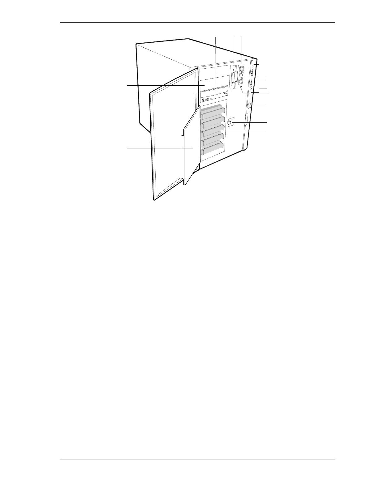
Front View
The following figure shows locations of controls and indicat ors on the front of
the system. A brief descr ipt ion of the cont rols and indicators follows the figure.
Note:
indicators are shown in t he following front and rear vi ew
figures. All controls and indicators shown on the stand-alone
unit are the same on the rack unit ex c ept f or orientation, as
the unit is mounted in the rac k on its side.
The stand-alone serv er unit and it s cont r ols and
2-4 Setting Up Your System
Page 25
ABC
D
L
E
F
G
H
I
J
K
A.
B.
C.
D.
E.
F.
G.
H.
I.
J.
K.
CD-ROM Drive Standard, factory-installed CD-ROM Drive
Diskette Drive Standard, factory-installed 3 1/2-inch diskette drive.
Power On/Off Button Press to turn system DC power on or off.
Sleep/Service Button Press to put system in power saving mode or service
mode.
Reset Button Press to reset system.
Front Panel LEDs (starting at top)
Power On
Disk Bay Power On
Hard Disk Activity
Fan Failure
Power Supply Failure
Six Hard Drive LEDs
(labeled 0 - 5)
NMI Button Used for system troubleshooting by qualified technical
System Security Lock Key operated lock to prevent unauthorized access to
EMI Shield Lock Latches metal EMI shield door.
Internal Drive Bays Holds up to six 1” high SCSI hot-swap hard disk drives.
Metal EMI Shield EMI shield for SCSI hard drives.
When lit (green), DC power is present.
When lit (green), DC power is present at hard drive ba y.
When lit (green), hard disk drive i s in use.
When lit (yello w ) , a cooli ng fan has f ail ed.
When lit (yello w ) , a power supply ha s failed.
When lit (yello w ) , associated drive failed.
personnel only.
server controls.
L.
5 1/4-inch Expansion Drive Bay Holds up to three 5 1/4-inch devices, including the
factory-installed CD-ROM drive.
Front Features and Controls
Setting Up Your System 2-5
Page 26
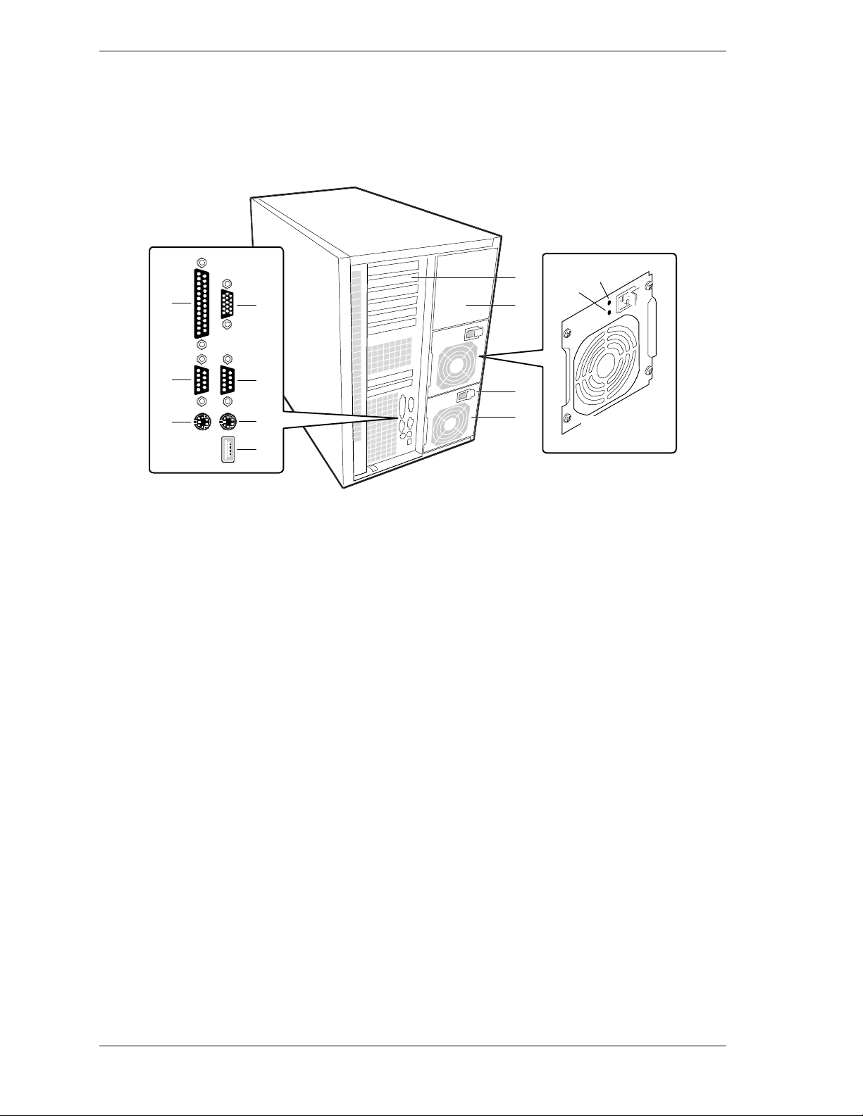
Rear View
The following figure shows the location of system controls, indicat ors, and
connectors on the rear of the system. The rack unit is similar except that it is
mounted in the rack on its side.
H
A
C
B
D
I
J
E
F
K
G
A.
Parallel Port Connector 25-pin parallel printer port connector.
B.
VGA Monitor Connector 15-pin monitor connector.
C.
Serial Port A (COM1) 9-pin serial COM1 port connector.
D.
Serial Port B (COM2) 9-pin serial COM2 port connector.
E.
Mouse Connector 6-pin PS/2-compatible mini-DIN mouse connector.
M
L
F.
Keyboard Connector 6-pin PS/2-compatible mini-DIN keyboard connector.
G.
USB Connector Single Universal Serial Bus connector.
H.
Expansion Slots 1 shared ISA/PCI slot, 1 ISA slot, and 6 PCI slots.
I.
Power Supply Bay Optional power supply bay for one backup power supply.
J.
AC Input Power Connector Supplies AC power to the power supply.
K.
Power Supply Fan Supplies cooling air to the power supply.
L.
Power Supply LED When lit, indicates AC power is available to power
M. Power Supply Failure LED When
2-6 Setting Up Your System
supply.
not
lit, indicates power supply failure.
Rear Features and Controls
Page 27

Installing the System
How you install the system depends on whether you have the stand-alone
pedestal unit or the rack-mounted unit. If you have the pedestal unit, install it at
your site and connect peripherals and power as explained next.
If you have the rack mounted unit, you need to install slide bars on the sides of
the unit before it can be installed in a standard E I A-compatible 19-inch
equipment rack. Yo u must also install rack extension brackets and slider
assemblies in the rack for the unit to mount on. See “Att aching the Outer Slide
Bars to the Chassis” and Pr epar ing the Rack” later in this chapt er for
procedures. Once your rack unit is in the rack, connect peripherals a nd power as
explained next.
Connecting Peripherals
If your system normally operates without a monitor, keyboard, or mouse (for
example, as a networ k server), you must install them to configure t he syst em.
You may remove them after running the System Setup Utility (SSU). For
information on running the SSU, refer to Appendix B of this User’s Guide.
Refer to the preceding figure and connect your keyboard, monitor, and mouse.
Connect any external peripheral de vices such as a pr inter by follow ing the
instructions included with the device.
!
CAUTION
System damage may result if the key boar d/mouse cable is
connected or disconnected when power is applied t o the
system.
Connecting the Power Cords
The system contains two 400-watt power supplies. Each power supply is
designed for automatic sensing of 115 or 230 Vac power, eliminating the need
for a line voltage selector switch. The power supplies operat e at a frequency of
50/60 Hz.
The system operates with both power supplies connect ed to po wer. Each power
supply is separately connected to a power source with its own power cord.
Connect each power cord as fo llows.
1.
Plug the female end of the AC power cord into its socket on the back of the
power supply.
You may need to slide the plug-lock away from the socket to allow
insertion of the plug into the socket.
Setting Up Your System 2-7
Page 28

To unplug the power cord, slide the lock away from the plug while
carefully pulling it out of the socket. Do not pull on the cord, only the
plug.
2. Plug the male end of the power cord into a wall-mounted power outlet.
Plug the male end of the power cord into an NEMA 5-15R outlet for
100-120 Vac.
Plug the male end of the power cord into an NEMA 6-15R outlet for
200-240 Vac.
If the power cords supplied with the system are not compatible with the AC wall
outlets in your r egion, obtain s uitable pow er cords that mee t the follow ing
criteria.
The power cord must be rated for the available AC voltage and have a
current rating that is at least 125% of the current rat ing of the system.
The power cord connector that plugs into the wall outlet must be
terminated in a grounding-type male plug designed for use in your region.
It must have certification marks showing cert ification by an agency
acceptable in your region.
The power cord connector t hat plugs into the syst em must be a n
IEC type CEE-22 female connector.
The power cord must be less than 1.8 meters (6.0 feet) long.
!
WARNING
Your system ships with two power cords, one for each power
supply. Do not attempt t o m odify or use the suppl ied AC
power cords if they are not the ex act type required.
Powering On the System
Power o n you r system as fo llows.
1. Make sure all external devices (monitor, keyboard, mouse) and power cords
are connected.
2. Make sure both AC power supply cords are connected to the system and
power outlets.
3. Power on the monitor and any other external devices.
4. Press the dc push-button power on/off switch on the front panel.
Verify that the dc power-on LED on the front panel is lit. If it is not lit,
ensure that the AC power cords are connected to funct ional AC power
sources.
2-8 Setting Up Your System
Page 29
Verify that the AC power-on and power supply failure LEDs on the
back of each power supply are lit. If the power supply failure LED is not
lit, ensure that the AC power cord is connected to a functional AC
power source.
!
WARNING
The DC push-button on/off switch on the front panel does
not turn off AC power. To turn off AC power, you must
unplug all power supply cords from either the power suppli es
or from the power sources.
without first turning off DC power
Do NOT turn off AC power
.
After a few seconds your s yst em begins the internal Power-On Self Tests
(POST). POST automat ica lly checks the system board, CP U modu le(s),
memory, keyboard, and most installed peripheral devices.
!
CAUTION
Always allow POST to complet e before powering down your
system.
!
CAUTION
The server management logic on your system board
monitors and logs system v oltage changes. When powering
down your system, you may experi enc e up to five seconds
delay from the time you pr ess the push-butt on power on/off
switch on the front panel and y our system poweri ng down.
This is normal system operat ion and is required by the
server management logic.
If you have problems powering on your system, refer to Chapter 5, “Solving
Pro blems , ” in this guide.
After you have successfully powered on your system, insert the
XPRESSBUILDER
E
follow the screen prompts to run E
CD ROM into the CD ROM drive, reboot t he syst em, and
XPRESSBUILDER
.
Setting Up Your System 2-9
Page 30

Converting to a Rack Mount Server Unit
You can convert a pedestal system to a rack mounted server unit using an
optional rack installat ion kit available from your dealer. The kit contains the
slide rails, bezel frame, and other hardware necessary for mounting the system
in an EIA-compatible 19-inch equipment r ack. Once you have the kit, use t he
following procedures to pr epar e the system for mount ing in a rack. You should
also follow any inst r uctions that may come with the k it.
Before starting the conversion, ensure that you have all the part s necessary for
the conversion (check t he pack ing slip t hat comes with t he rack inst allation kit).
You sho uld also obs e rve and impleme nt the fo llowing equipment rack warnings
and cautions.
2-10 Setting Up Your System
Page 31

Equipment Rack Warnings and Cautions
Observe and implement the following equipment rack war nings and cautions
before start ing t he co nvers ion.
!
WARNING
Anchor the Equipment Rack.
anchored to an unmov able support to prevent it from falling
over when one or more server s are extended in front of it on
slide assemblies. The anchors must be able to withstand a
force of up to 113 kg (250 lbs). You must also consider the
weight of any other dev ic e installed in the rack.
The equipment rack must be
Main AC Power Disconnect.
installi ng an AC power disconnect for the entir e rack unit.
This main disconnect m ust be r eadily ac c essible, and it must
be labeled as controlling power to the entire unit, not just to
the server(s).
Grounding the Rack Inst all at io n
electrical shock haz ar d, you must include a third wire saf ety
grounding conductor with the rack installati on. If server
power cords are plugged into AC outlets that are part of the
rack, then you must provide proper grounding for the r ac k
itself. If server power cords are plugged into wall AC outlets,
the safety groundi ng c onductor in each power cord provides
proper grounding onl y for the server. You must provide
additional, proper grounding for the rac k and other dev ic es
installed in it.
Overcurrent Protect ion.
line voltage source with up to 20 amperes of overcurr ent
protecti on. If the power system for the equipment r ack is
install ed on a branch cir c uit wit h m or e than 20 amper es of
protecti on, you m ust pr ov ide suppl em ental protection for the
server. If more than one server is installed in the rack, the
power source for each server must be from a separate
branch circuit. The over all current rating of a server
configured wit h thr ee power supplies is under 12 amperes.
You are responsible for
. To avoid a potential
The server is designed for an AC
!
CAUTION
Temperature
when install ed in an equipm ent rack, must not go below 5 °C
(41 °F) or rise above 35 °C (95 °F). Extr em e fluctuations in
temperature can c ause a variety of problems in your server.
Ventilation
airflow to the front of t he serv er to maintain proper cooling. It
must also include venti lation sufficient to exhaust a
maximum of 4,100 Btu' s per hour for the server. The rack
selected and the venti lation provided must be suitable to the
environment in whic h the server is used.
. The operating temperature of the server,
. The equipment rack must provide suffi ci ent
Setting Up Your System 2-11
Page 32

Converting the System Pedestal Unit
Converting your pedestal system to a rack mounted unit consists of:
removing the top and side covers
removing the bezel frame
installing a new bezel frame
inst a ll in g ha ndles
attaching slide rails to t he chassis
preparing the rack.
After the system unit is converted to a rack unit, install the unit in the rack (see
“Installing the Unit in the Rack” later in this chapter).
Removing the System Unit Covers
Remove the one piece syste m unit to p and side cover as fo llows.
1. Power down the syste m, discon nect any periphera l devices, and u nplug a ll
power cords.
2. At the back of the syste m unit, remove and save the screw from the top
cover (see the following figure).
Removing the Cover Screws
2-12 Setting Up Your System
Page 33

3. Grasp t he built-in handle on the back of the cover and, using an even pull,
slide the cover back about an inch u nt il it stops.
4. Pull the cover st r aight up and off the chassis. Set the cover aside.
5. Remove and save t he t wo screws holding the access (side) panel in place.
6. Grasp the built-in handle on t he back of the access panel a nd, us ing an even
pull, slide the cover back about an inch until it sto p s.
7. Pull the cover straight away fro m the chassis a nd set aside.
Replacing the Bezel Frame
The bezel frame must be replaced with a new bezel frame containing cutouts for
two chassis handles. Remove the bezel frame from the system unit and replace it
with a new bezel frame as follows.
1. Open the bezel door all the way to the left (as you face the unit) and lift the
door up slightly to free it from the bezel frame, then remove from the frame.
2. Remove the bezel frame by pressing its seven retaining tabs toward the
center of the chassis while pulling the frame away (see the fo llowing figure).
A.
B
A
Bezel Frame
B.
Frame Tabs (7)
Replacing the Bezel Frame
Setting Up Your System 2-13
Page 34

3. Install the new bezel frame by inserting the retaining tabs into their
correspond ing slot s on the chassis.
4. Install the bezel door by inserting the door onto the hinge pins on the
chassis. Shut t he bezel door.
Installing the Chassis Handles
Install the two chassis handles on the chass is a s follows.
Attaching the c hassis handles requires repositioning the
system unit on its side. The unit weighs between 85 pounds
(38 kg) and 100 pounds (45 kg), dependi ng on c onfiguration.
To avoid injury, mak e sure you hav e someone help you to
position the unit on it s side.
1. Turn the system unit o n its side, with the electronics bay facing up and the
front of the unit facing you.
2. Locat e the two rectangular cutouts in the bezel frame, one o n each side, and
the two threaded holes in each side of the chassis (see the following figure).
!
WARNING
3. Att ach t he handles, one to a side, to the chassis. Because of the bezel frame
configuration, the handles can only fit o ne way.
Align the two holes in the handle with the two threaded holes in the
chassis.
Fasten the handle in place w it h t wo scr ews fro m the k it.
Repeat for the second handle.
A
B
C
D
2-14 Setting Up Your System
Page 35

A. Bezel Frame
B. Rectangular Cutout
C. Chassis Handle
D. Screws
Attaching the Chassis Handles
Attaching the Outer Slide Bars to the Chassis
Note:
following procedure to attach the slide bars befor e m ounting
the unit in the rack. Observe all safety precauti ons,
warnings, and cautions noted throughout t his chapt er .
If you have a rack unit, you must use the
Each slide assembly cons ist s of a large outer bar, a center bar, and a small outer
bar. The large outer bar and the center bar attach to the rack unit. The small
outer bar attaches to the syste m chass is. As the slide assemb ly s hips as an
as sembl ed unit, you mu st remove the small outer bar from th e a sse mbly before
attaching to the chassis.
Remove the small outer bar from each slide asse mb l y and attach each bar to the
chassis as follows.
Position the slide assembly on a flat surface w ith t he sma l l outer bar down.
1.
Fully extend the three telescoping bars until they lock in place (see the
2.
following figure).
Setting Up Your System 2-15
Page 36

3. While press ing do wn on t he small outer bar safety latch (4 on the following
figure), pull the small out er bar out o f the assembly and set as ide for
installa tion on the c hass is .
Release the safety latch on the center bar (5 on the figure) and collapse
the large outer bar and center bar together.
Set the assembly aside for la ter installa tion in the rack.
4
1 2 3
5
1.
Large Outer Bar
2.
Center Bar
3.
Small Outer Bar
4.
Safety Latch on Small Outer Bar
5.
Safety Latch on Center Bar
Releasing the Small Outer Bar
2-16 Setting Up Your System
Page 37

4. Att ach each small o u ter bar to the chassis as fo llows.
Align the mounting holes in the bar to t he threaded ho les in the chassis
(see the following figure). The right angle end of the bar goes towar d t he
front of the chassis.
Secure the bar to the chassis with four scr ews from the kit.
1
2
4
3
1.
Threaded Holes in Ch assis
2.
Safety Latch
3.
Screw (1 of 4)
4.
Small Outer Bar (right angle end)
Attaching the Small Ou ter Bar to the Chassis
Setting Up Your System 2-17
Page 38

Prepari ng the Rack
Note:
following procedure to prepare the rack befor e m ounting the
unit in the rack. Observe all safety precautions, warnings,
and cautions noted thr oughout this chapter.
If you have a rack unit, you must use the
The converted syste m unit (or rack unit) mounts in a standard EIA-co mpat ible
19-inc h e quipment ra ck s imilar to that s hown in the following figure (shown
with three server units installed).
Typical Equipment Rack
Before you can mount the unit in the rack, you must insta ll a set of rack
extension brackets and slider ra ils to the rack. Do this as explained in the
following paragraphs.
Installing the Rack Extension Brackets
Install the four (two to a side) r ack ext ensio n bracket s on the rack as follows.
1. Determine where you want to install the server unit in the rack.
If the rack is empty, install the server unit in the bottom most position.
If there are units already installed, install your unit in the next empty
space from the bottom of the rack.
2. Remove a right-ang le ext ensio n bracket, two screws, and a bar nut fro m the
kit. The bar nut is a flat bar with four threaded holes.
2-18 Setting Up Your System
Page 39

3. Align the bracket behind the rack’s vertical edge and behind the mounting
holes in the vertical edge (see the following figure).
2
1
4
3
1.
Screw
2.
Rack Vertical Rail
3.
Bar Nut
4.
Right angle Extension Bracket
Installing the Extension Brackets
4. Deter mine where you want to attach the bracket on the rack’s vertical rail.
When determining where to attach t he bracket, be sure to allow space
for additional units.
Mark, with a pencil, the bracket to p and bottom hole locations on t he
rail.
5. Insert a screw through the marked top hole in the vertical rail and through
the top hole in the extension bracket.
6. Place a bar nut over the screw and loo se ly thread the screw into the bar nut.
7. Insert a screw through the marked bottom hole in the vertical rail and
extension bracket and loose ly thread the screw into the bar nut.
8. Insta ll the re maining t hree ext ension brackets, bar nuts, and screws.
Before insta lling, careful ly a lig n eac h bracket in exactly the same
vertical position as the first bracket.
After installing, check that the brackets ar e vertically alig ned and leve l
wit h eac h ot he r.
9. Tighten all the screws ho lding the brackets to the rack.
Installing the Slider Assemblies
Use the following procedure to inst all each slider assembly on the ext ensio n
brackets in the rack. Refer to the following figure while performing the
procedure.
Setting Up Your System 2-19
Page 40

1
22
4 6
3
2
5
4
2
6
2
1.
Back Extension Bracket
2.
8-32 Screw
3.
Flat Washer, Lock Washer, and 8-32 Nut
4.
Large Outer Bar
5.
Safety Latch on Center Bar
6.
Center Bar
7.
Front Extension Bracket
7
Installing the Slider Assembly
With the safety latch (5 o n the above figure) end of the slider assembly
1.
towards t he back of the rack, pr ess t he flat s ide o f the slider asse mb l y into
the U-shaped sections o f the previousl y installed extension
brackets (1 and 7).
Slide the slider assembly t owards the front of the rack until the end of the
2.
large outer bar (4) is flush with the end of the U-shaped section of the front
extension bracket (7).
Carefully slide t he center bar ( 6) towards the front of the rack until the
3.
oblong hole in the bar is over the first ho le in the large outer bar (4).
Insert a 8-32 screw through the oblong hole in the center bar, the ho le in
the large outer bar, and into the first hole in the front extension bracket.
Place a flat washer, lock washer, and a 8-32 nut on the screw and
loosely tighten.
2-20 Setting Up Your System
Page 41

4. Careful ly sl ide t he center bar (6 ) towar ds t he back of the rack unt il the
oblong hole in the bar is over the third hole from the front of the large outer
bar (4).
Insert an 8-32 screw through the oblong hole in the center bar, the ho le
in the large outer bar, and into the oblong slot in the front extension
bracket.
Place a flat washer, lock washer, and a 8-32 nut on the screw and
loosely tighten.
5. Secur e the back end of the large outer bar (4) to the back extension
bracket (1).
The end of the outer bar has four holes. T he extension bracket has two
holes and two elongated slots for fastening the bar.
Align two holes in the out er bar with a hole and slot in the bracket.
Which holes/slot s you use depends on the depth of the rack.
Insert an 8-32 screw through each of the two holes in the outer bar and
through the hole and slot in the extension bracket.
Place a flat washer, lock washer, and a 8-32 nut on each screw and
loosely tighten.
6. Check that the bars and brackets are pos itioned co r r ect ly in the rack.
7. Tighten all the screws holding the bars to the extension bracket s and rack.
Installing the Rack Unit in the Rack
Note:
following procedure to install the unit i n the rac k. Observe all
safety precautions, warnings, and cauti ons noted throughout
the procedures.
Install your converted unit (or rack unit) in the rack as follows.
If you have a rack unit, you must use the
Setting Up Your System 2-21
Page 42

!
WARNING
Anchor The Equipment Rack.
anchored to an unmov able support to prevent it from falling
over when one or more server s are extended in front of it on
slide assemblies. The anchors must be able to withstand a
force of up to 113 kg (250 lbs). You must also consider the
weight of any other dev ic e installed in the rack.
The equipment rack must be
Avoid Injury.
kg (85 lbs); the maximum confi gur ation weighs 45 kg (100
lbs). To avoid personal injury when installing the server,
have someone help you position the server in the rack.
Do not attempt to lift or mov e the server unit by the handles
on the power supplies.
1.
Pull the telescoping center bar (2 o n the following figure) out of each slider
The minimum server configurati on wei ghs 38
assembly on the rack unt il it locks in place.
2.
With someone helping you, use the handles on the sides of the rack unit to
lift and slide the unit into the slider asse mb l ies.
Align the small bars (1) attached to t he sides of the system unit with the
extended center bars (2).
Carefully slide t he server unit into the extended center bars until it stops.
Press in on the sa fety latches (4) on the small bars and care fu lly sl ide t he
server unit all the way into t he rack.
3.
Check that the server unit slides in and out of the rack. Grasp the two
handles on the sides of the unit and slowly pull the unit out and push it back
in.
4.
Connect all external perip herals and cables.
5.
Connect the two power supply cables to the back of the server unit and to a
power source.
6.
Power on the server unit.
2-22 Setting Up Your System
Page 43

2
3
1
4
2
1.
2.
3.
4.
Small Outer Bar
Center Bar
Large Outer Bar
Safety Latch
Installing the Server in the Rack
Setting Up Your System 2-23
Page 44

Page 45

Configuring Your System
Using the BIOS Setup
Using the Symbios SCSI Utility
Using the Optional RAID Controll er
Configuring Syst em B oard Jum pers
3
Page 46

This chapter describes t he Setup utilities that you can use to change your s yste m
configuration. The utilities described in this chapter include:
BIOS Setup Utility
Symbios SCSI Utility.
The BIOS Setup Utility is used to configure the system and any option boards
you may add . The B IOS Setup Utility is s tored in the system FL ASH memory.
You do not need a diskette to run the BIOS Setup Utility.
The Symb ios SCSI U tility is u s e d t o configur e the SCSI controller in you r
system, perform a SCSI disk format, or verify disk operation on the SCSI disk
drives. The utility is also used to configure any SCSI removable media devices
installed in your system. You do not need a diskette to run this utility as it is
accessible during system boot-up.
In addition, the following utilities are available for your use in configuring the
system. Informat ion on each utility is contained in the referenced appendix.
System Setup Utility (SSU) (see Appendix B, “System Setup Utility”)
Emergency Management Port (EMP) (see Appendix C, “Emergency
Mana gement Port ”)
FRUSDR Load Utility (see Appe nd ix C, “Emergency Management
Port”).
The System Setup Utility can be used to configure your system and any option
boards you may add t o your system. The SSU reads st o r ed syst em event
info rmatio n. App endix B c ontains info rma tion on the SSU.
The Emergency Management Port (EMP) is used for remote monitoring of the
server. The FRUSDR Load Utility can be used to update the field replacement
unit (FRU), sensor data record (SDR) and deskto p management interface (DMI)
flash components. Appendix C cont ains information on both ut ilities.
If your system is factory configured, you normally don’t need to run the SSU,
BIOS Setup, or Symbios SCSI Utility unless you want to change the password
or security features, add certain types of option boards or devices, or upgrade
your system board.
Also inc l u ded in t h is chapte r is information on se tting jumpers on the system
board for clearing
CMOS nonvolatile RAM (NVRAM)
Syste m passw ords.
3-2 Configuring Your System
Page 47

Using the BIOS Setup Utility
The BIOS Setup Utility is used to change system configuration parameters. Note
that many BIOS Setup parameters are also configurable with the SSU. However,
BIOS Setup Utility parameters that ar e sett able with the SSU are overwritten by
the SSU the ne xt t ime the SSU is run. The B IOS Set up Utility is resid ent in the
system Flash memory and does not r equire a disket te or an operating system
present to run.
You can access the BIOS Setup utility when you tur n on or reboot your system.
Use the following procedure to run the BIOS Setup Utility.
1. Power-o n o r reboot the system. The “Press <F2> to enter SETUP” message
displays.
2. Press F2. The B IOS Setup Utilit y s tart s and the M ain Menu is displa ye d.
The menu bar at the top of the Main Menu lists the following selections.
Menu Bar Selections
Menu Use
Main Use for b asic system confi gur atio n.
Adv anc ed Us e for sett ing the Advanced Feat ures available on your system.
Security Use to set User and Supervisor Passwords and Backup and Virus-
Check reminders.
Server Use for configuring Server Management features.
Boot Use to configure Boot Device priority.
Exit Exits current setup.
Use the arrow keys to select a menu or an ite m on a displayed menu. Press the
value keys (listed in the table below) to cycle through the allowable values for
the selected field. Use the Exit menu’s “Save Changes” selection to save t he
cur rent va lues on a ll the menus .
To display a submenu, posit ion the curso r on a selection that has a submenu and
press
. Selections with submenus are preceded by an arrow.
Enter
Refer to the following table for information on the keys you use with BIOS
Setup. These keys are also listed at the bottom of the Setup Menu.
Setup Menu Keys
Key Function in Setup Menu
F1 or Alt-H Get Help about an item.
ESC Exit t he cu r rent menu and r eturn to the previ ous menu.
Left or right arrow keys Move between menus.
Configuring Your System 3-3
Page 48

Key Function in Setup Menu
Up or dow n arr ow keys Move cursor up and down. The c ursor moves on l y to t he
- Select the p revi ous v alue for t he fi eld.
+ Select the n ext value for the fi eld.
F9 Load default configuration values for this menu.
F10 Sav e con f igurat ion values and exit.
Enter Execute command or Select submenu.
The following BIOS Setup Configuration tables show the default settings for the
BIOS Setup Utility. Recommended values are bold. The tables a lso pro vide a
space for you to record any changes you make to these set tings.
Main Menu
The follo wing table s hows the M ain M enu s e tt ings.
Setup Menu Keys
settings that you can change.
Main Me n u
Feature Choices Description Your Setting
System Time HH:MM:SS Sets the system time.
System Date MM/DD/YYYY Sets the system date.
Legacy Diskette A: Disabled
360KB
1.2 MB
720KB
1.44 MB
2.88 MB
Legacy Diskette B: Disabled
360KB
1.2 MB
720KB
1.44 MB
2.88 MB
Hard Disk Pre-delay Disabled
3, 6, 9, 12, 15, 21, or
30 seconds
Primary IDE Master Press Enter Refer to “Primary IDE Master and
Selects the diskette type.
Selects the diskette type.
Adds a delay before the first BIOS
access of a hard drive. Some hard
drives hang if accessed before they
initialize. The delay allows the drive
to initialize after power up, before
being accessed.
Slave Submenu. ”
Primary IDE Slave Press Enter Refer to “Primary IDE Master and
Slave Submenu. ”
Keyboard Features Press Enter Refer to “Keyboard Submenu.”
Processor Information Press Enter Information for al l process ors i s
3-4 Configuring Your System
Page 49

Main Me n u
Feature Choices Description Your Setting
described.
Language English (US)
Spanish, Italian
Fren ch , Germa n,
Japanese (Kanji)
Selects which language BIOS
disp la ys in.
Primary IDE Master and Slave Submenu
The following table shows t he sett ings for t he Primary IDE Master and Slave
submenu.
Primary IDE Master and Slave Submenu
Feature Choices Description Your Setting
Type Auto
None
CD-ROM
IDE Removable
ATAPI Removable
User
Cylinders 1 to 2048 Number of cylinders on drive. This
Auto allows the system to attempt
auto-detec ti on of t he drive t ype.
None informs the system to ignore
this drive.
Allows the manual entry of some
fields described below.
User allows the manual entry of all
fields described below.
field is changeable only for Type
User.
Heads 1 to 64 Number of read/write heads on
drive. This field is changeable only
for Type User.
Sectors 1 to 64 Number of sectors per track. This
field is changeable only for Type
User.
Maximum Capacity N/A Computed drive size. This field is
informational only for Type User.
Multi-Sector Transfer Disabled
2, 4, 8, or 16 sectors
LBA Mode Control Disabled
Enabled
32 Bit I/O Disabled
Enabled
Transfer Mode Standard
Fast PIO 1
Fast PIO 2
Fast PIO 3
Fast PIO 4
Determines the numb er of sectors
per block for multi-sector transfers.
This field is in formatio n al on ly for
Type Auto.
Enabling LBA causes logical block
addressing to be used in place of
cylinders, heads, and sectors. This
field i s inf ormational only for T ype
Auto.
Enabling allows 32 bit IDE data
transfers.
Selects the method for moving data
to and from the drive. This field is
informational only for Type Auto.
Configuring Your System 3-5
Page 50

Primary IDE Master and Slave Submenu
Feature Choices Description Your Setting
Ultra DMA Mode Disabled
Enabled
Selects the Ultra DMA Mode for
moving data to and from the drive.
Keyboard Submenu
The following table shows the settings for the Keyboard submenu.
Keyboard Submenu
Feature Choices Description Your Setting
NumLock Auto
On
Off
Key Click Disabled
Enabled
Keyboard auto-repeat
rate
30/sec
26.7/sec
21.8/sec
18.5/sec
13.3/sec
10/sec
6/sec
2/sec
Selects power-on state for Num
Lock.
Enables or disables key click.
Selects the number of times per
second a key repeats while it is
held down.
Keyboard auto-repeat
delay
1/4 sec
1/2 sec
3/4 sec
1 sec
Selects delay before key repeat.
Advanced Menu
The following table shows the Advanced Menu set tings.
Advanced Menu
Feature Choices Description Your Setting
Plug and Play OS No
Yes
Res et Co nfi guration
Data
PCI Configuration Press Enter Refer to “PCI Conf iguration
I/O Device
Configuration
No
Yes
Press Enter Refer to “I/O Device Configuration
Select Yes if you are booting a
Plug and Play capable operating
system.
Select Yes if you want to clear the
system configuration data during
next boot. System automatically
resets to No in next boot.
Submenu.”
Submenu.”
3-6 Configuring Your System
Page 51

Advanced Menu
Feature Choices Description Your Setting
Use Multiprocessor
Specification
1.1
1.4
Selects version of multiprocessor
specification to u se. Som e
operating systems require version
1.1 for compatibility reasons.
Large Disk Access
Mode
System Wakeup
Feature
Pause Before Boot Enabled
Advanced Chipset
Control
LBA
CHS
Disabled
Enabled
Disabled
Press Enter Refer to “Advanced Chipset Control
PCI Configuration Submenus
The following tables show the settings for the PCI Device Embedded SCSI
submenu and PCI Devices submenu. The submenus should only be changed by
qualified technical personnel.
Leave the PCI Device Embedded SCS I subm enu at factorydefault setti ngs. This submenu should only be changed by
qualified technical personnel.
Select LBA for IDE drives.
If enabled, the system powers up
upon receiving a “magic packet” on
LAN, ring on COM2, or PME
interrupt from a PCI board.
Enables five second delay before
booting operating system.
Submenu.”
!
CAUTION
PCI Device, Embedded SCSI Submenu
Feature Choices Description Your Setting
Option ROM Scan
Enable Master Enabled
Latency Timer Default
Active Termination Disabled
Enabled
Disabled
Disabled
0020h
0040h
0060h
0080h
00A0h
00C0h
00E0h
SCSI A On
Enables option ROM scan of the
selected device. Used to enable
embedded Symbios SCSI
controller
Enabled selects the device as a
PCI bus master.
Minimum guaranteed time, in units
of PCI bus clocks, that a device
may be master on a PCI bus.
Caution: Do not change this setting
unless you fully understand the
priority of this device on the PCI
bus.
Selects the setting of the onboard
Configuring Your System 3-7
Page 52

PCI Device, Embedded SCSI Submenu
Feature Choices Description Your Setting
SCSI B On
SCSI A & B On
SCSI termination.
Single-Ended
Force/Auto Set
Force A and B
Force B, Auto A
Force A, Auto B
Auto
If set for Force Single, the SCSI
channel defaults to Single-Ended
operation. Auto-Set uses hardware
detection to determine single vs.
double-ended operation.
The PCI Devices submenu (see the following table) should only be changed by
qualified technical personnel.
!
CAUTION
Leave the PCI Devices submenu at factory-default setti ngs.
This submenu should onl y be changed by qualif ied technical
personnel.
PCI Devices Submenu
Feature Choices Description Your Setting
Option ROM Scan Enabled
Disabled
Enables option ROM scan of all
devices other than the onboard
SCSI controllers.
Enable Master Enable d
Disabled
Latency Timer Default
0020h
0040h
0060h
0080h
00A0h
00C0h
00E0h
Enabled selects all devices as a
PCI bus master, other than
onboard SCSI controllers.
Minimum guaranteed time, in units
of PCI bus clocks, that a device
may be master on a PCI bus.
Caution: Do not change this setting
unless you fully understand the
priority of this device on the PCI
bus.
I/O Device Configuration Submenu
The following table shows the settings for t he I/O Device Configurat ion
submenu.
I/O Device Configuration Submenu
Feature Choices Description Your Setting
COM 1: Disabled
Enabled
Auto
Auto forces BIOS to configure the
port.
OS Controlled forces OS to
3-8 Configuring Your System
Page 53

I/O Device Configuration Submenu
Feature Choices Description Your Setting
(Serial Port A)
OS Controlled configure the port.
Base I/O Address 3F8
2F8
3E8
2E8
Interrupt IRQ 3
IRQ 4
COM 2:
(Serial Port B)
Base I/O Address 3F8
Interrupt IRQ 3
Parallel Port Disabled
Mode Output only
Disabled
Enabled
Auto
OS Controlled
2F8
3E8
2E8
IRQ 4
Enabled
Auto
OS Controlled
Bi-directional
EPP
ECP
Selects the base I/O address for
COM port 1.
Selects the IRQ for COM port 1.
Auto forces BIOS to configure the
port.
OS Controlled forces OS to
con figure the port.
Selects the base I/O address for
COM port 2.
Selects the IRQ for COM port 2
Auto forces BIOS to configure the
port.
OS Controlled forces OS to
con figure the port.
Selects parallel port mode.
Base I/O Address 378
278
Interrupt IRQ 5
IRQ 7
DMA channel DMA 1
DMA 3
Floppy disk controller Disabled
Enabled
PS/2 Mouse Auto
Disabled
Enabled
Advanced Chipset Control Submenu
The following table lists the settings for the Advanced Chipset Control
submenu.
Selects the base I/O address for
LPT port.
Not availa ble in ECP o r EPP
modes.
Selects the IRQ for LPT port.
Selects the DMA for LPT port.
Enables onboard diskette
controller.
Enables or disables onboard
mouse. Disabling frees up IRQ 12.
If enabled, the OS can determine
whether to enable or disable
mouse.
Configuring Your System 3-9
Page 54

Advanced Chipset Control Submenu
Feature Choice Description Your Setting
Address Bit Permuting Disabled
Enabled
Base RAM Step 1 MB
1 KB
Every location
Extended RAM Step 1 MB
1 KB
Every location
L2 Cache Enabled
Disabled
ISA Expansion Aliasing Enabled
Disabled
To be enabled, there must be a
power of 2 number of row s, all row s
must be the same size, and all
populated rows must be adjacent
and start at row 0. Two-way or four-
way permuting is set automatically
based on memory configuration.
Tests base memory once per MB,
once per KB, or every location.
Tests extended me mory once per
MB, once per KB, or every location.
When enabled, secondary cache is
sized and enabled. For Core Clock
Frequency-to-System Bus ratios
equal to two, BIOS automatically
disables the L2 cach e.
When enabled, every I/O access
with an address in the range
x100-x3FFh, x500-x7FFh,
x900-xBFF, and xD00-xFFFh is
internally aliased to the range
0100-03FFh before any other
address range checking is
performed.
Memory Scrubbing Disabled
Enabled
Read Prefetch for
PXBOA
Read Prefetch for
PBXOB
16
32
64
16
32
64
When enabled, BIOS automatically
detects and corrects SBEs.
Configures the number of Dwords
that ar e prefetched on Mem ory
Read Multiple commands.
Configures the number of Dwords
that ar e prefetched on Mem ory
Read Multiple commands.
Security Menu
The following table lists the settings for the Secur it y Menu.
Note:
requires a password for entering Setup. The passwords are
not case sensitiv e.
Feature Choice Description Your Setting
User Password i s Clear Status only; user cannot modify.
Enabling the Administr ator Password fiel d
Security Menu
Once set, this can be disabled by
3-10 Configuring Your System
Page 55

Security Menu
Feature Choice Description Your Setting
Set setting it to a null string, or by
clearing password jumper on
system board (see “Configuring
System Board Jumpers,” in this
chapter).
Administrator Password
is
Set User Password Press Enter When the Enter key is pressed, the
Set Administrator
Password
Password on Boot Disabled
Clear
Set
Press Enter When the <Enter > key is pressed,
Enabled
Status only; user cannot modify.
Once set, this can be disabled by
setting it to a null string, or by
clearing password jumper on
system board (see
System Board Jumpers
user is prompted for a password;
press Esc key to abort. Once set,
this can be disabled by setting it to
a null string, or by clearing
password jumper on system board
(see “Configuring System Board
Jumpers” later in this chapter).
the user is prompted f or a
password; press ESC key to abort.
Once set, this can be disabled by
setting it to a null string, or by
clearing password jumper on
system board (see “Configuring
System Board Jumpers” later in
this chapter).
Requires password entry before
boot. System will remain in secure
mode until password is entered.
Password on Boot takes
preceden ce over Secure Mo de
Boot.
Configuring
).
Fixed Disk Boot Sector Normal
Write Prot ect
Secure Mode Timer 1 min
2 min
5 min
10 min
20 min
1 hr
2 hr
Secure Mode Hot Key
(Ctrl-Alt- )
Secure Mode Boot Disabled
Video Blanking Disabled
[ ]
[A, B, ..., Z]
(0-9)
Enabled
Enabled
Write-protects bo ot sector on ha rd
drive to protect against viruses.
Period of keyboard or PS/2 mouse
inactivity specified for secure mode
to activate. Password is required
for secure mode to function.
Cannot be enabled unless at least
one password is enabled.
Key assigned to invoke the
Quicklock feature. Cannot be
enabled unless at least one
password is enabled.
System boots in secure mode.
User mus t ent er password to
unlock system. Cannot be enabled
unless at least one password is
enabled.
Blank video when secure mode is
activated. User must enter
password to unlock system. Cannot
Configuring Your System 3-11
Page 56

Security Menu
Feature Choice Description Your Setting
be enabled unless at least one
password is enabled.
Floppy Write Protect
Disabled
Enabled
When secure mode is activated,
diskette dr ive is write p rot ected.
User mus t ent er password to
disable. Cannot be enabled unless
at least one password is enabled.
Server Menu
The following table list s the settings for the Server Menu.
Server Menu
Feature Choices Description Your Setting
System Management Press Enter Refer to “System Management
Submenu.”
Console Redirection Press Enter Refer to “Console Redirection
Submenu.”
Processor Retest Yes
No
EMP Password Switch Disabled
Enabled
Select Yes to have BIOS clear all
processor status and retest the
processor(s) on boot-up.
Enables or disables EMP
password.
EMP ESC Sequence +++
User
EMP Hangup Line
String
Modem Init String AT&FS0=1S14=0&
High Modem Init String Characters above 16 are entered
EMP Access Mode Pre-Bo ot Only
EMP Restricted Mode
Access
EMP Direct
Connect/Modem Mode
ATH
User
D0
Always Active
Disabled
Disabled
Enabled
Direct Connect
Modem Mode
Escape string for the modem on
EMP port. This field accepts up to 4
characters.
Hangup string for the modem on
EMP port. This field accepts up to 8
characters.
This string accepts up to 20
characters to set up the modem.
here.
Pre-Boot: EMP enabled during
power down or POST.
Always Active: EMP always
enabled.
Disabled: EMP disabled.
Power down, front panel NMI,
Reset Control via EMP can be
disabled/disabled.
Connect directly to POST or use a
modem.
3-12 Configuring Your System
Page 57

System Management Submenu
The following table lists the settings for the System Management Submenu.
System Management Submenu
Feature Choices Description Your Setting
System Event Logging Disabled
Enabled
Clear E vent Log Yes
No
Assert NMI on AERR Disabled
Enabled
Assert NMI on BERR Disabled
Enabled
Assert NMI on PERR Disabled
Enabled
Assert NMI on SERR Disabled
Enabled
FSB ECC Check by
Chipset
FSB ECC Check by
Processor
Server Management
Information
Disabled
Enabled
Disabled
Enabled
Press Enter Displays system serial and part
When enabled, system events will
be logged by BIOS and BMC.
Clears the s ystem event l og (S EL)
in BMC if Yes is selected.
When enabled, generates a
nonmaskable interrupt (NMI) on an
address parity error (AERR).
When enabled, generates an NMI
on a bus error (BERR).
When enabled, generates an NMI
on a parity error (PERR). To
activate, the system error (SERR)
option must be enabled.
When enabled, generates an NMI
on SERR.
Enables host single and multi-bit
error checking and reporting
feature in the chipset.
Enables host single and multi-bit
error checking and reporting
feature in the processors.
numbers and server management
controller revisions.
Configuring Your System 3-13
Page 58

Console Redirection Submenu
The following table lists the settings for the Console Redirection Submenu.
Console Redirection Submenu
Feature Choices Description Your Setting
COM Port Address Disabled
3F8
2F8
3E8
IRQ # 3 or 4
None
Baud Rate 9600
19.2k
38.4k
115.2k
Flow Control No Flow Control
CTS/RTS
XON/XOFF
CTS/RTS + CD
When enabled, console redirection
uses the I/O port specified. 3F8 is
typically COM 1 and 2F8 is typically
COM2.
When console redirection is
enabled, this displays the IRQ
assigned per the address chosen in
the COM Port Addr ess field .
Communications line dependent.
Communications line dependent.
Boot Menu
The following table lists the settings for the Boot Menu.
Boot Menu
Feature Choices Description Your Setting
Floppy Check Disabled
Enabled
BIOS Boot Spec
Support
Boot Device Priority Press Enter. Refer to “Boot Device Priority
Hard Drive Press Ent er. Refer to “H ard D r ive Submenu. ”
Removable Devices Press Enter. Refer to “Removable Devices
Maximum Number of
I20 drives
Message Timeout
Multiplier
Limited
Enabled
1
4
1, 2, 8, 10, 50, 100,
1000
If enabled, syste m verifies disket te
type on boot. Disabled results in a
faster boot.
Enable only if the total number of
hard drives is l ess than eight.
Submenu.”
Submenu.”
Selects maximum number of I20
drives assigned a DOS drive letter.
All ti meou t values are mu ltiplied by
this number.
Boot Device Priority Submenu
The following table lists the settings for the Boot Device Priority Submenu. Use
the up or down arrow keys to select a device, then press the <+> or <-> keys to
move the device higher or lower in the boot priority list.
3-14 Configuring Your System
Page 59

Boot Device Priority Submenu
Boot Priority Device Description Your Setting
1. Diskette Drive Attempts to boot from
drive A.
2. Removable Devices Attempts to boot from a removable
media device.
3. Hard Drive Attempts to boot from a hard drive
device.
4. ATAPI CD-ROM
Drive
Hard Drive Submenu
The following table gives the settings for the Hard Drive Submenu. For options
on this menu, use the up or down arrow keys to select a device, then press the
<+> or <-> keys to move the device higher or lower in the boot priority list.
Option Description
1. Hard Drive #1 (or
actual drive string)
2. Other Bootable
Devices
IDE drives have a suffix attached to the drive ID string:
PM - hard drive on Primary Master Channel
PS - hard drive on Primary Slave Channel
SCSI CD-ROMs are displayed here because the onboard Symbios SCSI BIOS
tr eats CD-ROMs as har d driv es.
SCSI removable drives also appear here.
Covers all the boot devices that are not reported to the system BIOS through
the BIOS boot specification mechanism. This includes all PCI boards that are
not BIOS boot compliant (legacy) as wel l as ISA cards tha t are not PnP
compliant. ISA legacy cards boot first before non BIOS boot compliant PCI
boards (in scan order from lowest slot to highest).
Attempts to boot from an ATAPI
CD-ROM drive.
Hard Drive Submenu
Configuring Your System 3-15
Page 60

Exit Menu
You can make the following selections on t he Exit Menu. Se lect an option using
the up or down arrow keys, then press Enter to execute the option. Pressing Esc
does not exit this menu. You must select one of the ite ms from the menu or
menu bar to exit.
Exit Menu
Choices Description
Exit Saving Changes Exits after writing all modified Setup item values to CMOS.
Exit Discarding Changes Exits leaving CMOS unmodified.
Load Setup Defaults Loads default values for all Setup items.
Load Custom Defaults Loads settings from custom defaults.
Save Custom Defaults Saves present Setup values to custom defaults.
!
CAUTION
Verify that custom defaults are saved
before exiting. Failure to do so can
resu lt in system malfunct io n.
Discard Changes Reads the previous value of all Setup items from CMOS.
Save Changes Writes all Setup item values to CMOS.
Using the Symbios SCSI Utility
The Symbios SCSI Utility detects the SCSI ho st adapter located on the system
board. Use the utility to:
change adapter and SCSI device default values
check and/or change SCSI device sett ings that may conflict w ith tho se of
other devices in the server
perform low-level formatting or verify operations on SCSI disk drives.
Running the Sy mbios SCSI Utility
Power-on the system. The system boots u p.
1.
When this message appears on the video monitor
2.
Press Ctrl-C to start the Symbios SCSI Utility
Press
Ctrl+C
The utility start s and t he Ma in Menu d isp la ys.
3.
3-16 Configuring Your System
to r u n the util ity.
Page 61

Symbios SCSI Utility Main Menu
. Status
Adapter Por t No IRQ Level Curr e nt Next Boot NVRAM Found
SYM53C810 2000 11 On On Yes
SYM53C896 3000 11 On On* Yes
SYM53C896 3400 11 On On Yes
Change Adapter Status – Press ENTER to change adapter Next Boot Status.
Adapter Boot Order – Press ENTER to select and change boot order of each SCSI adapter.
Additional Adapter Configuration – Not used.
Display Mode-Verbose – Press ENTER to change display mode.
Mono/Color – Press ENTER to change display from black/white to color.
Language
Help
Quit
*Next Boot Status for this controller must be turned OFF if you install the optional Mylex AcceleRAID 250 Controller board in
your system. Refer to “Change Adapter Status” above.
The following keys are active for all SCSI Configuration scree ns:
Active Keys
Key Action
Arrows Up and down arrows move from one parameter to another
within a screen.
Enter Displays options for a configurable parameter. Selects an
option.
Esc Moves back to previous screen or parameter or EXIT if at
the Main menu.
Changing the Adapter and Device Configurations
The SCSI Configurat ion Utilit y Main Me nu lists t he o nboard S CS I adapt er s and
shows their current set tings. The adapters control the operation of the SCSI
devices in your system (hard disk drives or removable media devices).
Highlight an adapter and press
1.
Select “ Adapter Setup” and press
2.
Enter
Enter
.
. The Adapter Set up screen d isp la ys.
Configuring Your System 3-17
Page 62

Adapter Set u p Scr een
Description Recommended Setting or Display Only Your Configuration
SCAM Support On
Parity On
Host SCSI ID 7
Scan Order Low to High
Removable Media
Support
CHS Mapping SCSI Plug and Play Mapping
Spinup Delay (sec) 2
Help
Restore Default Setup
Exit This Menu
Highlight the function you want to change and press
3.
None
Enter
. You are
prompted to save changes when you exit the configuration utility.
To change device configuration parameters, perform the following steps.
At the SCSI Configuration Utility Menu, se lect “D evice Se lect ions” and
1.
press
Select the SCSI device you are reconfiguring and press
2.
If you are configuring SCSI Hard Disk Drives, see the fo llowing "SCSI
. The Devices 0 to 7 screen displays.
Enter
Enter
.
Hard Disk Drives" table.
If you are configuring SCSI Removable Media Devices, see the
following "SCSI Remo vable Med ia De vice s" table for recommended
settings.
3-18 Configuring Your System
Page 63

SCSI Hard Disk Drives
Recommended Settings or
Descriptions
Device Selections Press Enter for menu. Select
Sync Rate 40
Wi dth (bits) 16
Disco nnect On
Display On ly
device and press Enter.
Your Configuration
01 2 34 5
Read/Write I/O
timeout (sec)
Scan for device at
boot time
Scan for SCSI
LUNS
Queue Tags On
10
Yes
No
SCSI Remo vable Media Dev i c es
Recommended Settings or
Descriptions
Device Selections Press Enter for menu. Select
Sync Rate 10
Wi dth (bits) 8
Disco nnect On
Read/Write I/O
timeout (sec)
Display On ly
device and press Enter.
10
Your Configuration
Dev 0 Dev 1 Dev 2 Dev 3
Scan for device at
boot time
Scan for SCSI
LUNS
Queue Tags On
Highlight the function you want to change and press
3.
Yes
No
Enter
prompted to save changes when you exit the configuration utility.
Note:
select “Form at” or “Verify” from the Device Setup menu.
If you wish to format a disk or verify disk media,
Configuring Your System 3-19
. You are
Page 64

Using the Optional RAID Controller
The following paragraphs provide an overview of the optional Build-to- Order
RAID c ontro lle rs. Included is in formation on t he fact or y inst alled controllers
and RAID configurations.
Factory Installed Controller
One of the options available for your syste m is the dual channel Mylex
AcceleRAID 250 Controller board, which gives your system the added security
of fault tolerance.
If you order a system with the RAID co nt ro ller, the syst em is pre-configured at
the factory. Refer to the “RAID Configurations” table below to determine how
the RAID controller was configured at the factor y. If you want to reconfigure
disk arrays and logical drives, you must run the AcceleRAID 250 BIOS
Configuration Utility. If you want to change the RAID level, you must run the
Mylex Disk Array Controller Utilities (DACCF) software. Refer to the
AcceleRAID 250 documentation included with your system for information on
running the AcceleRAID 250 BIOS Configuration Utility and the DACCF
Utility.
Add-on Control ler
If you are adding the RAID controller to an existing system, the AcceleRAID
250 BIOS Configuration Utility allows you to configure disk arrays and logical
drives in your system. Since the utility resides in the AcceleRAID 250 BIOS on
the R AID controlle r, its o peration is independent of the ope rat ing system in your
server. Refer to Chapter 4 in this User’s Guide for information on installing an
add-in option board. Refer to Chapter 4 of the AcceleRAID 250 Installation
Guide for information on running the AcceleRAID 250 BIOS Configuration
Utility.
Note:
SYM53C896 controller must be turned OFF if you instal l the
optional Mylex AcceleRAID™ 250 Controller boar d in y our
system. Refer to “Symbios Configurati on Utilit y ” found earlier
in this chapter.
Ensure a jumper is install ed on J P 10 of t he Mylex
AcceleRAID 250 Controller board. Refer to the Mylex
AcceleRAID Installation Guide for the location of jumper
JP10.
Next Boot Status for the first Symbios
3-20 Configuring Your System
Page 65

DACCF Configuration Utility
The DACCF utility is included with the AcceleRAID™ 250 Controller. The
AcceleRAID™ 250 supports various versions of RAID technology (referred to
as RAID levels). To use any RAID level, you must co nfigure t he RAID
controller using the DACCF Configuration Utility prior to installing your
Network Operating Syste m. For an explanation of this utility, refer to the Disk
Array Controller Configuration Utilities Manual that was shipped with the
controller. Chapter 2 (Preparing the Array) covers array hardware preparation,
configuration, and initialization. After completing the steps in Chapter 2, you
can inst all your N etwor k O per ating Syste m.
Factory RAID Configurations with SCSI Hard Drives
Number of
Hard Drives
1 JBOD 1 JBOD (RAID 0) JBOD is an acronym for Just a
2 1 2 Mirroring (RAID 1) Drives are paired and mirrored.
3 5 3 Striping with Parity (RAID 5) Data is striped across
4 5 3 plus 1 hot
5 or more _ _ The first four disks are as stated above. The
RAID Level
Configured
Hard Drives
in Array Description
Bunch Of Disks. Each drive can operate
independently as with a common host bus adapter;
or multiple drives may be spanned and seen as a
single very large drive. No redundancy is provided.
All data is 100% duplicated on an equivalent drive
(fully redundant).
several physical dr ives. Parity protection i s used for
data redundancy.
Striping with Parity (RAID 5) Data is striped across
spare drive
three physical drives. Parity prot ection i s used for
data redundancy. This drive is used as the “Hot
Spare.”
rem aining disks are not p art of the array, but are
ready to be configured.
Configuring Your System 3-21
Page 66

Configuring System Board Jumpers
The following paragraphs contain procedures for setting system board jumpers
to:
clear the CMOS
clear a password.
A jumper is a small plastic-encased conductor (shorting plug) that slips over two
jump e r p ins on the jumper blo c k.
!
CAUTION
Electrostatic discharge (ESD) can damage the system
board. Modify t he system boar d only at an ESD workstation.
Otherwise, wear an antistatic wrist strap att ac hed to chassis
ground.
The following figure shows t he location of the system board jumpers. T he
jumper configurations and default settings are given in the table immediately
af ter the f ig ure.
13711 9 5
J6J1
3-22 Configuring Your System
System Board Jumpers
Page 67

System Board Jumper J6J1 Summary
Function Pins (default in bold) What it Does at System Reset
CMOS Clear 1-2, Protect CMOS
2-3, Clear CMOS
Pas sword Clear 5- 6, Protect
6-7, Clear
Recovery Boot
Leave the Recovery Boot jump er at the factory default
setting.
qualified per sonnel .
9-10, Normal
10-11, Recovery
!
CAUTION
This jumper should onl y be set by technically
Preserves content s of NVRAM.
Replaces contents of NVRAM
with manufacturing default
settings.
Maintains current system
password.
Clea rs current sy stem
password.
System attempts to boot using
BIOS stored in flash ROM
memory.
BIOS attempts recovery boot,
loading BIOS code from diskette
into the flash device. Typically
used when BIOS code is
corrupted.
Moving System Board Jumpers
!
Before doing the following procedures, make sure your
system is powered off and the two AC power cords are
unplugged fr om the bac k of the chassis. F ailure to
disconnect power befor e m ov ing the jumpers can result in
personal injur y and equipm ent damage.
Observe static pr ec autions. Use an antistatic wri st str ap.
Use this general procedure as an aid for configuring system board jumpers. See
the following paragraphs for details of setting the jumpers.
Power off the system, disconnect any peripherals, unplug the system power
1.
cords from the system and power source, and remove the access cover (see
Chapter 4, “Upgrading Your System,” for access cover removal).
CAUTION
Configuring Your System 3-23
Page 68

2. Locate the position of the jumper block on the syste m board (see the
preceding figure and table for jumper locat ions and settings).
To change a jumper setting, use a pair of needle-nose pliers o r your
fingers to remove the jumper from its current position.
Position the jumper over the two pins for the desired setting and press it
ont o the pins .
Be ca re ful no t to be nd t he pin s .
3. Install the access co ver, co nnect any disconnected peripherals, p lug in the
power cords, and power up the system.
Resetting the CMOS NVRAM
Reset the CMOS NVRAM as follows (also refer to the general procedure given
above).
1. Power down the syste m, disco nnect any periphera ls, unplug t he po wer cor d s
from the syste m, and remo ve t he access co ver.
2. Move the CMOS Clear jumper from pins 1-2 to pins 2-3 (see the preceding
jumper figure and table for jumper locations).
3. Connect the power cor ds to the syst em and power on the system.
Wait for POST to complete and for t hese message s t o appear.
“NVRAM cleared by jumper”
“Press F2 to enter Setup”
This automatically reprograms CMOS and RTC to their default settings.
4. Press F2 to enter Setup and make any changes necessary.
5. Press
to save the new setup configuration and exit Setup.
F10
6. Power off the system and unplug the power cords from the system.
7. Mo ve t he CMOS C lear jumper back to pins 1-2.
8. Replace the access cover, reconnect any peripherals, plug in the power
cords, and power on the system.
9. Run the BIOS Set up Utility to check t he configurat ion of your system.
Cleari ng a nd Ch an ging Pas sw or d s
Use the following procedure to clear and change passwords (also refer to the
general procedure given earlier).
1. Power down your system, disconnect any attached per ipherals, unplug t he
power cords from the syste m, and re move the access cover.
2. Move the Password Clear jumper from pins 5-6 to pins 6-7 (see the
preceding jumper figure and table for jumper locations).
3-24 Configuring Your System
Page 69

3. Plug in the power cords, power on the system, and wait for POST to
complete. This automat ically clears t he o ld password.
4. Power off the system and unplug the power cords from the system.
5. Mo ve t he Password Clear jumper back to pins 5-6.
6. Replace the access cover, reconnect any peripheral devices, plug in the
system power cords, and power on the system.
7. To specify a new passwor d, r un the BIOS Setup Utility as described earlier
in th is chap ter.
Configuring Your System 3-25
Page 70

Page 71

Upgrading Your System
Observing Static Precautions
Preparing Your System
Maintaining the Equipment Log
Removing the Access Panel
Opening the Subchassis and Electronics Bay
Upgrading the System Board
Installing Option Boards
Installi ng Hard Disk Dri ves
4
Installi ng Removable Media Devi ces
Page 72

This chapter includes procedures for
replacing/upgrading the real-time battery, Pentium Xeon processor
cartridge, and DIMM modu les o n t he syste m board
adding optional ISA and PCI boards
installing 3 ½-inch SCSI hard drives
installing optional 5 1/4-inch devices (tape drive, other device).
Contact your sa les represe nt ative or dealer for a list of approved optional
peripheral devices.
!
WARNING
The DC push button on/off switch on the front panel does
not turn off system AC power. Also, + 5vdc is present on t he
system board whenever the AC power cord is connected
between the system and an AC outlet. Before performing
any procedures, first power off the dc push button switch
located on the front panel. Make sure your system is
powered off and the AC power cord i s unplugged from the
system. Failure to disconnect power before opening your
system can result in per sonal injury and equipment dam age.
!
CAUTION
The server management logic on the system board monit or s
system voltage changes. When powering down your system,
you may experience a 1- to 5-second del ay from the time
you press the push button power on/off switch and your
system powering down. This is normal system operation and
is required by the serv er management logic.
!
CAUTION
Operating your system with the access cover removed can
damage system components. For proper cooling and ai rflow,
always replace the access cover before powering on.
Observing Static Precaut ions
An electrostat ic discharge (ESD) can damage disk drives, o pt ion boards, and
other components. You can provide some ESD protection by wearing an
antistatic wrist st r ap att ached to chassis ground (any unpainted meta l surface)
when handling system components.
4-2 Upgrading Your System
Page 73

Electronic devices can be easily damaged by static electricity. To prevent
damage, keep them in their protective packaging when they are not installed in
your system.
Preparing Your System for Upgrade
Depending on the upgrade, you need one or more of the following tools:
Phillips screwdriver (#1 bit and #2 bit)
flat-head screwdriver
sma ll nee d le no se plie r s
pen or pencil
ESD workstation or antistatic wrist strap (recommended).
Preparing the Equipment Log
Use the equipment log form at the end of this guide to record the model and
serial numbe r of your system, all ins talled opt ions, and any other pertinent
information specif ic to your syst em. You need this information when
configuring your system.
Upgrading Your System 4-3
Page 74

Removing the Access Cover
To install options in your system, you must first remove the access co ver on the
right side of the syst em (as viewed from the front).
!
CAUTION
For proper cooli ng and airflow, do not operate the system
with the access cover removed. Always replace the cover
before powering on t he system.
!
WARNING
Turn off your system, disconnect any external devic es, and
unplug the system power cords from the AC wall outlet
before removi ng the acc ess cov er .
Remove the access co ver as follows.
1.
Power off the system and unplug t he po wer cables from the AC wall outlets.
If connected to a surge protector or uninterruptible power source, unplug
from the AC outlet.
2.
Disconnect all external devices and unplug all device cables.
3.
Remove the two Phillips head screws securing the cover to the back of the
chassis (see the following figure). Save t he screws for reat taching the cover.
4.
Grasp the built-in handle on t he back of the access cover. You might also
want to grasp the front handle of the access co ver. The front handle is a
rounded, rectangular depressio n in the front middle of the cover.
Note:
two hands to remove the cov er.
5.
Slide the access co ver to war d the back of the chassis until it stops (about an
inch). This unlocks the locking fingers behind the access cover.
6.
Pull the access cover straight away from the chassis to disengage the lock ing
tabs. Set the access co ver as ide.
The access cover fits tightl y to t he c hassis. Use
4-4 Upgrading Your System
Page 75

Removing/Installing the Access Cover
Installing the Access Cover
Install the acces s cover as follows.
1. Check that you have not left any too ls or loose parts inside the system
chassis.
2. Make sure all option bo ar ds ar e firmly seat ed in their respective slots and
that all interior cables are proper ly connected.
3. Insert t he meta l tabs on t he top and bottom of the access co ver into their
slots on the chassis. Slide the cover towar d t he front o f the syste m, as far as
it will go.
4. Secure the access co ver with the two previously removed retaining screws.
5. Connect any external devices, connect all cables, and plug in the system’s
power cables.
Upgrading Your System 4-5
Page 76

Opening the Subchassis and Electronics Bay
There may be times during system upgrade that you need to open the subchassis
and electronics bay. Both may be swung aside for access to co mponent s.
Open the subchassis and e lect ronics bay as follows.
!
CAUTION
For proper cooli ng and airflow, do not operate the system
with the access cover r em ov ed, t he subchassi s open, and
the electroni c s bay open. Al ways replac e the cover and
close the subchassis and elect r onics bay before powering
on the system.
!
WARNING
Turn off your system, disconnect any external devic es, and
unplug the system power cords from the AC wall outlets
before removi ng the acc ess cov er , opening the subchassis,
and opening the electr onics bay.
Open the subchassis and e lect ronics bay as follows.
1.
Power off the system and unplug t he po wer cables from the AC wall outlets.
If connected to a surge protector or an uninterrupt ible power supply, unplug
from the AC outlet.
2.
Disconnect all external devices and unplug all device cables.
3.
Remove the access cover as previou sly described.
!
CAUTION
All cabling to the I/O panel on the back of t he system m ust
be disconnected before opening the electr onic s bay. Failure
to disconnect all cabling to the bay can result in seri ous
damage to system components.
4.
Label and disconnect all peripheral cables att ached to t he I/O panel on the
back of the system (D in the following figure).
5.
Remove the two screws o n the to p and botto m edges of the chassis that
secure the subchassis and electronics bay (see A in the following figure).
4-6 Upgrading Your System
Page 77

A
B
D
Opening the Subchassis and Electronics Bay
C
6. Rotate the subchassis to the left, away from the main chassis, until it stops
(B in the above figure).
7. Label and disconnect all cabling to the electronics bay (D in the figure).
8. Rotate t he electronics bay to the right, away fro m the main chassis, until it
stops (C in the above figure).
Closing the Subchassis and Electronics Bay
Close the subchassis and electronics bay as follows.
1. Rotate the electronics bay to the left, towards the main chassis. Leave
enough space for connecting cables.
2. Connect all the previously d isco nne cted cables to the back of the electro nics
bay.
3. Close the electronics bay.
4. Rotate the subassembly to the right, towards the main chassis, as far as it
goes.
5. Check for pinched wires a nd ca bles, clear as necessar y.
6. Secure the subassemb l y and electronics bay with the two previously
removed screws.
Upgrading Your System 4-7
Page 78

7. Connect all the previousl y disco n nected cables to the I/O panel on the back
of the chassis.
8. Insta ll the access cover as previously described.
Upgrading the System Board
The following paragraphs provide procedures for upgrading the system board in
your system. Topics covered include:
replacing the real-time clock battery
installing and removing Pentium II Xeon processor cartr idges
insta lling and remov ing D I MMs.
!
CAUTION
Electrostatic discharge (ESD) can damage add-in boards
and other components. T o pr ev ent ES D dam age; place
them on an antistatic surf ac e. Modify the system board onl y
at an ESD workstation. Other wise, wear an antistatic wri st
strap attached to c hassis ground.
Replacing the Real-time Clock Battery
You may need to replace the real-time clock lithium battery as it ages. The
battery (Vendor Part #CR2032) is a commodity part available through many
vendors. Replace the battery as follows.
!
CAUTION
Danger of explosion if battery is incorrectl y repl ac ed.
Replace only with sam e or equivalent type recommended by
manufacturer. Dispose of lithium batteries as required by
local ordinanc e or as norm al waste if no local ordinance
exists. Do not expose the com ponent to excessive heat or
fire. Keep all batteries away from children.
!
CAUTION
Observe static pr ec autions. Use an antistatic wri st str ap.
4-8 Upgrading Your System
Page 79

!
WARNING
If the system was running, proc essors and heat si nk s on the
board may be hot. To avoid the possibility of a burn, be
careful when rem ov ing or i nstalling components near the
processor(s).
1
Power off the system, disconnect any peripherals, and unplug the power
cords from the AC power source.
2.
Remove the access cover as previou sly described.
3.
Insert the tip of a small flat-bladed screwdriver under the plastic tab on the
plastic retainer (A in the following figure).
4.
Gently push down on the screwdriver to lift the battery (B) and retainer.
5.
Remove the battery from its socket (C).
B
A
Replacing the Real-Ti me Clock Battery
6.
Dispose of the battery accord ing to any local ordinances.
7.
Remove the new lithium battery from its package and care fully insert it in
the battery socket, with the plus sign up (see above figure).
8.
Reinsta ll the plastic retainer o n the batt ery socket.
C
9.
Replace the access co ver, r econnect any peripherals, plug in the power
supply cords, and t urn on the system.
10.
Run the System S etup Ut ilit y to restor e the conf igur a tio n s ettings.
Upgrading Your System 4-9
Page 80

Installing /Removing the Processor Cartridge
The following paragraphs provide procedures for installing and removing the
Pentium II Xeon Processor Single Edge Contact ( S.E. C. ) cartridge. Use these
procedures when upgrading or replacing your processor(s).
Each processor is packaged in a S.E.C. cart r idge. The cart r idge includes the
processo r core with an integrated 16 KB primary (L1) cache, secondar y (L2)
cache, heat sink, and a back cover. The processors are supported by one or more
voltage regulator modules (VRM) on the system board, depending on the
numb e r o f inst alled process or s .
Each S.E.C. cart r idge installs in a Slot 2 connector on the baseboard. E ach slot
must contain either a pro cessor cartridge or a terminat ion board (if there are less
than fou r proce s s or s ins ta lled) . The VRM modules a re ins talled in a bank of
VRM sockets adjacent to the processors.
Note:
install ed processors m ust be m atched for speed. If replaci ng
a processor, the replacement processor must mat c h the
speed of all install ed pr oc essors. If upgrading a processor,
all processors must be upgraded to match.
Electrostatic discharge (ESD) can damage components;
place them on an antistatic surface. Update the system
board using an antistat ic wrist strap attached to chassis
ground.
If the system was running, any pr oc essor and heat sink
install ed on the board is hot. To avoid the possibility of a
burn, let the components cool for 10 minutes befor e
continui ng with t hese procedur es.
Your system may have up to four processors. All
!
CAUTION
!
WARNING
Installing a Processor Cartridge
Use the following procedure to inst all a processor cartridge.
Note:
speed. If your system has l ess than four pr oc essors, and
you are adding one, then you must r em ov e the t ermination
board in the empty Slot 2 connec tor. Remove a termination
board the same way as a cartri dge.
4-10 Upgrading Your System
All installed proc essors must be matched in
Page 81

1. Power off the syste m, disco nnect any att ached per ipherals, and unplug the
system’s power cords from the power sources.
2. Remove the access cover as previousl y descr ibed.
3. Carefull y remo ve t he foam cover from over the electr onics bay.
4. Remove a new processor cartridge from its antistatic package and place it on
a grounded static-free surface or conductive foam pad.
Note:
preinstalled in the bottom most slot (PROC1) on the system
board. Some systems may hav e m ore, depending on how it
was configured. W hen adding a processor cartridge, install it
in the next empty slot up fr om the bott om slot .
All syst ems ship wi th a p rocessor cartridge
5. Align the cartr idge so that the heat sink (D in the following figure) faces
away from the system board.
If installing a termination board, align the board so that the white barcode
label faces away fro m the system board.
E
A
B
D
C
A. S.E.C. cartridge
B. Retention module guide rails
C. Cart ri dge tabs
D. Processor heat sink (face away from baseboard center)
E. Push tabs inward on S.E.C. cartridge to seat processor
Installing a Processor S.E.C. Cartridge
6. Ensure that t he tabs at the top of the cartridge are completely open; i.e.,
pulled outward, away from the center of the cartridge (C in the preceding
figure).
Upgrading Your System 4-11
Page 82

Note:
“Attaching Pr oc essor Cartr idge Tabs” for procedures.
If tabs are not attached to the car tridge, see
7. Insert the cartridge into the guide rails of the retention module (B in the
preceding figure) and carefully push into the module unt il resistance is fe lt.
8. Close the two tabs by pushing them towards each other (E in the preceding
figure) until the cartridge is fully seated.
9. Attach the retention bracket as follows.
With the bracket in the open position (perpendicu lar to t he front of the
retention module), slide the open hinge at the left of the bracket into its
slot at the left of the retention module.
Turn the bracket to the right until it reaches the ret ention module.
Slightly pull the tab outward and to the left to open the latch at the back
of the tab.
As you open the latch on the back of the tab, slide the right edge of the
bracket onto the retention module and release t he t ab to lock the bracket
in place.
10. Install the r eq uired VRM modules (single processor syst ems come with two
VRM modules installed in VRM sockets 1 and 2). As you add processors,
yo u need to install addition al VRM modules .
For pro cessor PROC2, install a VRM module in socket 3.
For pro cessor PROC3, install a VRM module in sockets 4 and 5.
For pro cessor PROC4, install a VRM module in socket 6.
11. Reinsta ll the foam cover on the electro nics bay.
12. Reinstall the access co ver as pr eviou sly described.
13. After you have installed a new processor, run the BIOS Setup Utility to
configure its speed. Refer to Chapter 3, “Configuring Your System.”
If your new S.E.C. processor cartridge does not have tabs installed, install them
as follows.
1. Align the tab so that its triangular end (with two round pegs) points away
from the center of the cartridge (see the preceding figure).
2. Slightly spread open the tab so that the two round pegs on the tab fit into two
round holes at the corner of the cartridge. Use care in opening the tab to
prevent breakage.
3. Repeat steps 1 and 2 for the second tab.
4. Proceed w ith insta lling t he S.E. C. processor cartridge (see “ I nst alling a
Processor Cartridge,” above).
4-12 Upgrading Your System
Page 83

Removing a Processor Cartridge
Use the following procedure to remove a processor cartridge.
1. Power off the syste m and remove the access cover as previous ly described.
2. Remove the foam cover from the electronics bay.
3. With your right thumb on the ret ent ion module bracket ( A on the following
figure), wrap your right index finger around tab (B).
A
B
C
A. Retention module bracket
B. Bracket tab
C. Latch
Opening the Latch
4. Use your right index finger to slightly pull the tab outward and to the left. A
latch (C) releases when the tab is pulled, making it unnecessary to pull the
entire bracket.
5. With the latch (C) released, rot at e the bracket 90º to t he left until
perpendicular to the front of the retention module.
6. Grasp the bracket and move (not rot ate) it to the right to disengage the
bracket hinge, then remove the bracket fro m the cart r idge.
Upgrading Your System 4-13
Page 84

7. Pull the two tabs (C on the following figure ) on the cartridge straight away
from the system board to disengage t he cartridge from the syste m board.
A
B
C
B
D
C
A. S.E.C. cartridge
B. Retention module guide rails
C. Tabs on S.E.C. cartridge
D. Processor heat sink
Removing the Processor
8. Pu ll the processor cartridge straight o ut of the syste m board and retent ion
module. Place it on a grounded, static-free sur face o r conductive foam pad.
9. Put the old processor cartridge in conductive foa m and store in an ant ist atic
package.
10. Install a new processo r cart ridge (see “Installing a Processo r Cart r idge,”
next). If not installing a pro cessor, install a termination board the same way
as a cartridge and remove the appropriate VRM modu le(s).
Installing DIMM Modules
Main memory resides on a memory module that plugs into the system board.
The memory module contains fou r banks of DIMM socke ts, with each bank
containing four so ckets, for a total of 16 DIMM sockets. The banks are labeled
A, B, C, and D. The sockets are labeled J1 through J16. The following figure
shows the mod ule and sockets.
4-14 Upgrading Your System
Page 85

E
J16
J15
J12
J11
J8
J7
J4
J3
D
C
B
A
A. Memory bank A (install first)
B. Memory bank B (install second)
C. Memory bank C (install third)
D. Memory bank D (install last)
E. Memory module connector
J14
J13
J10
J9
J6
J5
J2
J1
Memory Module
Each socket holds a single 72-bit DIMM module with 32MB, 64MB, 128MB, or
256MB of ECC memory. When all sockets are filled, the system board supports
a maximum of 4 GB of memory using sixteen 256MB DIMMs.
You must insta ll DIMMs by first filling bank A (see above figure), then fill
bank B , C, and D, in that or der. Each bank must be fille d before going to the
next ba nk.
Insta lling D I MMs require s that you first remove t he memory module from the
syste m, t hen add (o r remove) DIMMs to the memory module as required.
Remove the module and install or remove the DIMM modules as described in
the following paragraphs.
Removing the Memory Module
Th e memory module must f ir st be r emov ed from th e sys tem to install or re move
DIMMs. Re mo ve the memory modu le as follows.
1. Remove the access co ver as previously described.
2. Remove the foam cover from the top of the electronics bay.
Upgrading Your System 4-15
Page 86

3. Car efully pull the memory module out o f its connector on the system board
(see the following figure).
4. Slide the module straight out from the syste m board unt il it clears t he gu ide
rails.
5. Place the module co mponent- s ide up on a non-conductive, st atic-free
surface.
Removing the Memory Module
Installing DIMMs
Use the following procedure to inst all DIMMs. If you need to remove a DIMM,
see “Removing DIMMs,” next.
1. Remove the memory module as previously described.
Install DIMMs with gol d- plated edge connectors in the
memory module gold- plated sockets. Mixing di ssimilar
metals might cause memor y failures and data corrupti on.
2. Hold the DIMM by its edges and re move from its antistatic package.
4-16 Upgrading Your System
!
CAUTION
Page 87

3. Align the two notches in the bottom edge of the DIMM with the keyed
socket on the memory module (see the following figure).
Installing the DIMM
!
CAUTION
Use care when inserting a DI MM. Applying too much
pressure when inserting a DIMM can damage a socket or
ejector lever. A pply just enough pr es sure on t he DIMM
ejector levers to lock the DIMM.
4. Careful ly insert the DIMM into the so cket and press down firmly on the
DIMM until it is fully seated.
5. Gently push the plastic ejector levers on the so cket ends to the upright
position.
6. Repeat the above st eps for each additional DIMM.
7. Reinstall th e memory module ( se e “Ins talling the Memory Modu le,” below).
Upgrading Your System 4-17
Page 88

8. Reinstall the foa m cover o n t he e lectronics bay.
9. Reinstall the access cover as previous ly described.
10. Connect all external cables a nd t he po wer cor ds to the system.
11. Run the SSU to configure the system and to properly attr ibute ECC memor y
(see Chapter 3, “Configuring Your System”) .
Removing DIMMs
Use the following procedure to remove DIMMs.
1. Remove the memory module as previously described.
2. Place the module co mponent- s ide up on a non-conductive, st atic-free
surface.
Use care when removi ng a DIMM. Appl yi ng too muc h
pressure when removing a DIMM can damage a socket.
Apply just enough pressure on the DIMM ejector lev ers to
release the DIMM.
!
CAUTION
3. Gently press the e ject or levers ou t and do wn to eject a DIMM from its
socket.
4. Hold the DIMM by its edges and care ful ly remove it from the socket. Place
the DIMM in an antistat ic package.
5. If installing a new DIMM, see “Inst a lling DIMMs,” above, otherwise
continue with this procedure.
6. Reinsta ll the memory mo d ule (see “I ns ta lling the Memory Modu le,” next).
7. Reinsta ll the foa m cover o n t he e lectr onics bay.
8. Reinstall the access cover as previous ly described.
9. Connect all external cables and power cords and power up the system.
10. Run the SSU to configure the system and to set up advanced memory
attributes.
Installing the Memory Module
Rein st all the me mo r y mod u le as fo llo ws.
1. Check that all DIMMs are firmly seated in their sockets o n t he memory
module.
4-18 Upgrading Your System
Page 89

!
CAUTION
To avoid damage to the memory module, you must support
the module until it is correctly inserted and firmly seated in
its connector on the system board.
2.
Hold the memory module by its edges and align it with the guide rail at the
back of the electro nics bay.
3.
Insert the memory module through the guide rails and into the connector on
the system board.
4.
Firmly seat the memory module in the connecto r.
5.
Reinsta ll the foam cover on the electro nics bay and the access cover.
Installing Option Boards
The following paragraphs describes how to install and remove ISA and PCI
option boards. T he s yst em board has one ISA bus expansion co nnector and
seven PCI bus expansion connect ors (see the following figure).
The 32-bit PCI bus is divided into PCI Segment A and PCI Segment B, each
with the following connector s:
PCI A has thr ee expansion boar d co nnectors (PCI A1, A2, a nd A3)
PCI B has four expans ion board connectors (PCI B0, B1, B2 , and B3) .
The ISA connector accepts a half-lengt h board only, and is shared with PCI B3
(meaning that you can install either an ISA board or a PCI board in the shared
slot). PCI connector PCI A1, adjacent to t he processors, accepts a half-length
board only. The remaining PCI connectors accept up to full length boards.
The segmented high-performance PCI buses allow use of networking
technology, such as 100 MB/second Ethernet NICs, with a minimum of effort
and without concern for I/O bottlenecks. Each segmented bus offers up to 133
MB/second burst transfers.
Upgrading Your System 4-19
Page 90

A
B
C
A. I SA connector (use half-length board only)
B. Six PCI connectors (top to bottom in figure)
First four co nnectors: PCI B3, B 2, B1, B0
Next two connectors: PCI A3, A2
C. PCI connector A1 (use half-length board only)
Locating the PCI and ISA Slots
Installation Considerations
Newer ISA boards, designed for Plug-and-Play systems, are automaticall y
configured by the system without any user intervent ion. Older ISA boards must
be manually configured. Once the manual configuration is complete, the Plugand-Play boards are co nfigured around t he manually configured boar ds without
causing any resource conflicts.
The ISA boards that are not Plug-and-Play must be manually configured
following the instructions supplied with the board. The configuration is defined
to the system by creating the ISA configuration file when running the SSU. If
adding a non- Plu g and Play ISA optio n board, ru n the SSU before ins talling the
board (see Appendix B, “System Setup Utility”).
4-20 Upgrading Your System
Page 91

Control ler / A dapter Har d war e C o nfi gurati o ns
The following table lists the option boards you may add to your system that
req uire s p ecific inst allatio n slots.
Option Board Hardware Configurations
Memory
Option Board I RQ
Address I/O Address Option Slot
Mylex
AcceleRAID 250
(SecuRAID 210)
Contr oller Board
Mylex
AcceleRAID
1100 (SecuRAID
530) Controller
Board
Set by
BIOS
Installing an Option Board
Install an option board as follows.
Power off the system, disconnect any peripherals, and unplug the AC power
1.
cords from power.
Remove the access cover as previou sly described.
2.
Remove the foam cover from the electronics bay.
3.
Remove an expansion slot screw and cover (see the following figure).
4.
Set by
BIOS
Set by BIOS PCI Slot B2 (see PCI/ISA
Slot Location illustration
above)
!
CAUTION
Observe static pr ec autions. Use an antistatic wri st str ap.
Hold the option board by its edges and remove it from its protective
5.
wrapper. Do not touch board components or connectors.
Set the board down on an antistat ic sur face.
6.
Record the option board serial number in the equipment log.
7.
Upgrading Your System 4-21
Page 92

A
B
C
Installing an Option Board
8. Set any board jumpers o r switches as descr ibed in the documentation that
comes with the option board.
9. Ho ld the option board by its top edge or upper corners and insert it into the
expansion slot until it is firmly seated. The tapered foot of the option board
retaining bracket must fit into the mating slot in the expansion slot.
10. Secure the board in place, using the previously removed slot cover and
screw .
11. Connect any necessary ca bles and peripherals to t he board and syste m.
12. Reinsta ll the foam cover on the electro nics bay.
13. Replace the access co ver and power o n the syste m.
Removing an Option Board
Use the following procedure to remove an option board.
Note:
empty slots to maintain the electromagnetic emi ssions
characteri stic s of the system and to assure proper cooling of
the system component s.
1. Power off the system, disconnect any peripherals, unplug the power cords
from their power so urce, and remove the access cover.
Expansion slot cover s must be installed on all
2. Remove the foam cover from the electronics bay.
3. Disconnect any cables t hat may be attached to t he option board you are
removing.
4-22 Upgrading Your System
Page 93

4. Remove and save the option board retaining bracket screw.
5. Hold the board at each end and carefully pull it out of its connector. Make
sure that you do not scrape the board against other components.
6. Remove t he board fro m the expansio n slot and place it in an antistat ic
wrapper. If you are replacing a board, see "Installing an Option Board,"
otherwise continue.
7. Insta ll an expansio n slot cover over the vacant slot and secure w ith the
previously removed screw.
8. Reinstall the filler board retaining bar and secure with the previously
removed screw.
9. Replace the foam cover on the electronics bay, install t he access panel,
connect any periphera ls, and po wer on the system.
Upgrading Your System 4-23
Page 94

Installing Hard Disk Drives
Your system supports up to six, 1-inch high, hot-swap, wide SCSI low voltage
drives (LVD). The drives inst all in the drive bay at the front of the syste m (see
the following figure). The drive bay is accessed by opening the front panel,
unlocking the metal door (if locked), and opening the metal door.
A
B
C
D
A. Front panel
B. Metal EMI shield door
C. Metal door latch
D. 3 1/2-inch SCSI hard drive bay
3 1/2-Inch SCSI Hard Drive Bay Location
Each optional hard drive must be mounted in a plastic hard disk t r ay, and the
tray and hard drive installed in the drive bay. The SCA connecto r on the back of
the drive plugs into the syste m’s inter na l SCSI backplane. The connector
connects the SCSI drive power and data lines to the SCSI backplane. T he
backplane also acts as the t ermination point for all installed SCSI hard dr ives
and sets the hard drive IDs auto mat ically.
The following paragraphs include procedures for installing optional SCSI hard
drives and for hot-swapping a failed SCSI hard drive.
4-24 Upgrading Your System
Page 95

Installing an Optional SCSI Hard Disk Drive
Install an optional SCSI hard disk drive as follows.
!
CAUTION
Observe static pr ec autions. Use an antistatic wri st str ap.
1.
Turn off the system and disconnect all power cords from their power
sources.
2.
Remove the 3 1/2-inch hard disk drive from its protective wrapper and place
the drive on an antistatic surface.
3.
Record the drive model and serial number in the equipment log.
!
CAUTION
If the drive comes with driv e r ails, do not use them. Remove
any rails already att ac hed.
4.
Orient the drive and carrier as shown in the following figure.
Installing the Hard Drive Carrier
5.
Secure the carrier to the drive with the four supplied screws.
6.
Open the front panel on the server by grasping the right edge (as you face
the front) and swing the panel out.
7.
Press in on the plastic latch securing the met al door and open the door.
If the door is locked with a padlock, remove it.
Upgrading Your System 4-25
Page 96

8. Hold the carrier by its handle, pos it ion it in front of an open slot, and start it
into the guide rails.
9. Carefull y push the carr ier and drive part way into the bay.
10. Pull down on the carrier handle and continue pushing the carrier into the
bay.
As you push in, the two rounded notches in the handle (B in the
following figure) slide onto the two round pegs inside the drive bay
(A in the figure).
When the pegs are fully seated in the notches, push t he hand le st r aight
up (C in the figure) to lock.
Press the rounded tab o n the right of the carr ier to the left unt il it clears
the edge of the bay and snaps into place.
A
Installing an Optional SCSI Hard Drive
11. Close the metal door and secure with the plastic latch. If removed, install the
padlock and lock the metal door.
12. Close the front panel.
13. Configure the syste m for the new SCSI hard drives (see Chapter 3,
“Configuring Your System”).
Hot-Swapping a SCSI Hard Disk Drive
A SCS I har d drive c an be hot -swappe d (removed) f rom the syste m if it fa ils a nd
replaced with another S CSI hard dr ive, a ll without shut ting down your system.
Hot-swap a SCSI hard disk drive as fo llows.
1. Open the front panel and the metal door to the hot-docking bay. If the metal
door is locked with a padlock , remove it.
2. Check the bank of yellow LEDs on the front panel to determine which drive
is bad.
C
B
4-26 Upgrading Your System
Page 97

Note:
continuously lit yellow LED on the front panel. T he LE Ds and
corresponding hard drives are numbered 0 thr ough 5, f r om
top to bottom (for exam ple, drive 0 is the top-most hard drive
in the bay and drive 5 is the bott om-most drive in the bay).
A failed SCSI hard drive is indic ated by a
3. Press t he rounded t ab o n the right of the carr ier to war ds t he center o f the
drive (B in the following figure) while gently pulling down the carrier
handle (A in the figure ).
A
B
Unlocking the Carrier
4. With the handle pulled down, pull the carrier and drive out of the bay.
5. Place the carrier and drive on an antistatic surface.
6. Insta ll a replacement carr ier and SCSI hard dr ive as previously described.
7. Close and lock (if appropriate) the metal door, and close the front panel.
Installing Removable Media Devices
Your system supports up to three SCSI removable media devices, including the
factory inst alled SCSI CD-ROM dr ive . The C D-RO M dr ive is s hipped inst alled
in the bo ttom slot, w ith the re maining two s lots available for installa tion o f
optional devices (tape drive, other removable devices). Additional de vices
should be insta lle d in the first avai lable slot from the top.
Your system ships with a four - connector narrow SCSI cable. The SCSI CDROM drive is connected as the last device on t he SCSI cable and is terminated.
Additional single-ended SCSI r emovable media dev ices ca n be connect ed to the
remaining connectors.
If you are adding or removing a SCSI removable media device, consider the
following:
A tape drive SCSI address assignment is 2.
Upgrading Your System 4-27
Page 98

If a SCSI tape drive is connected along with the SCSI CD-ROM on the
SCSI controller, SCSI termination must be removed from the tape drive.
Use the following procedures to install or remove optional 5 1/4-inch removable
media devices.
Installing a 5 1/4-Inch Media Device
Install an optional 5 1/4-inch device in the removable media bay as follows.
1. Power off the system, disconnect all installed peripherals, and unplug all
system power cords fro m their power sources.
!
CAUTION
Only single-ended S CS I devic es are supported by the
narrow SCSI channel. Connec ting different SCSI devic es
can result in electri c al dam age to the system board and
peripherals.
!
CAUTION
Do not install hard drives in the 5 1/4-inch device bay. The
drives cannot be properly cooled in the bay. Also a hard
drive generates EMI and is more susceptible to ESD in the
bay.
2. Open the front panel for access to the removable media device bay.
3. Remove the EMI meta l shield from the slot that you are using for the
optional device.
Push the tab (A on the following figure) on the left side of the shield to
the right to disengage it fro m the bay.
Remo ve the shield and save it. Reinstall the shield i f you remove t he
device and don’t replace it.
4-28 Upgrading Your System
Page 99

A
Removing the EMI Shield
!
CAUTION
Observe static pr ec autions. Use an antistatic wri st str ap.
4.
Remove the device from its protect ive wrapper and place it o n an antistat ic
surface. Record the device model and serial nu mber in the equipment log.
5.
Set any device jumpers or switches before you install the device. See the
documentation that comes w ith the device for jumper o r sw itch information.
Note:
them. Remove any rail s already attached. Use only the r ails
in the accessory pack that comes with your system.
6.
Remove the two rails and four mounting screws fro m your accessory pack
If the device comes with devic e r ails, do not use
and attach them to the device.
Position the device and rails as shown in the following figure.
Secure the rails to the device with the four screws.
Upgrading Your System 4-29
Page 100

C
D
B
A
A. Tape drive or other rem ovable device
B. Tab on rail
C. Screws (4)
D. Rails (2)
Installing the Device Rails
7. Align the device with the device slot guide rails and carefully slide the
device into the slot until the device locks in place.
8. Remove t he access co ver and open the subchassis for access to the po wer
and signal cables and the back of the device (see “Removing the Access
Cover” and “Opening the Subchassis and Electronics Bay,” described earlier
in th is chap ter).
9. Locate a power cable and the SCSI cable, depending on the device being
installed.
10. Connect the signal and power cables to t he device. T he co nnectors on the
cables are keyed and can only be connected one way.
11. Check your connect ions, close t he subc hass is, install the access co ver, and
close the front panel.
12. Connect any external peripherals, plug in the system power cor ds, and turn
on the system.
13. Co nfigure t he syste m for the new device (see Chapter 3, “Configuring Your
System” ).
4-30 Upgrading Your System
 Loading...