

Page 1
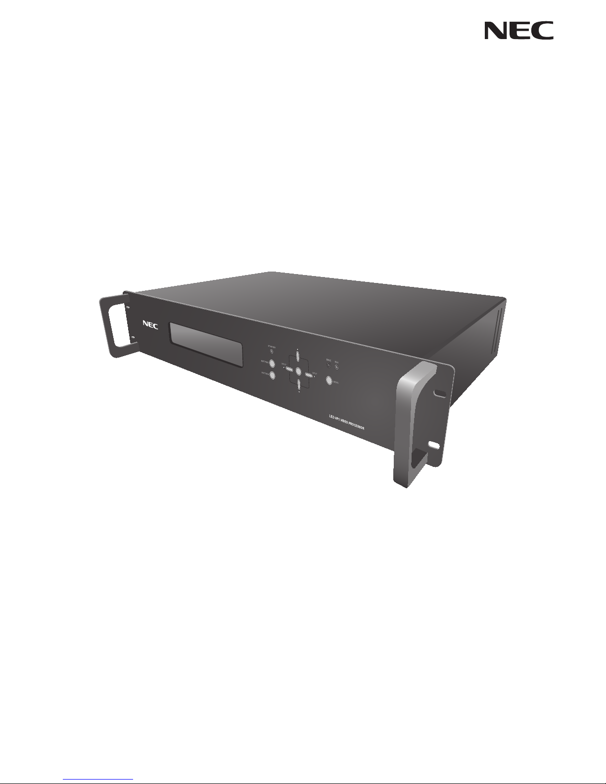
User’s Manual
Video Processor
LED-VP1
Page 2

Index
Declaration of conformity .......................................................................................................................... English-1
Important Information ................................................................................................................................ English-2
Safety Precautions, Maintenance & Recommended Use .......................................................................English-3
Contents ...................................................................................................................................................... English-4
Parts Name and Functions ........................................................................................................................ English-5
Front panel .............................................................................................................................................. English-5
Rear panel ............................................................................................................................................... English-6
Connections ...............................................................................................................................................English-7
Connecting an External Device ............................................................................................................... English-7
Connecting the Power ............................................................................................................................. English-7
Connection and setting ............................................................................................................................. English-8
Basic Operation .......................................................................................................................................... English-9
Troubleshooting ....................................................................................................................................... English-11
Appendix ................................................................................................................................................... English-12
Specifications ........................................................................................................................................ English-12
Communication command specifications .............................................................................................. English-13
Dimensional Drawing ............................................................................................................................. English-14
Manufacturer’s Recycling and Energy Information ...............................................................................English-15
Page 3
English-1
Declaration of conformity
For USA
FCC Information
1. Use the attached specified cables with the LED-VP1 (D000LE) video processor so as not to interfere with radio and television
reception.
(1) Please use the supplied power cord or equivalent to ensure FCC compliance.
(2) Please use a good quality shielded video signal cable.
Use of other cables and adapters may cause interference with radio and television reception.
2. This equipment has been tested and found to comply with the limits for a class A digital device, pursuant to Part 15 of the FCC
Rules. These limits are designed to provide reasonable protection against harmful interference when the equipment is operated
in a commercial environment. This equipment generates, uses, and can radiate radio frequency energy and, if not installed and
used in accordance with the instruction manual, may cause harmful interference to radio communications.
Operation of this equipment in a residential area is likely to cause harmful interference in which case the user will be required to
correct the interference at his own expense.
If necessary, the user should contact the dealer or an experienced radio/television technician for additional suggestions.
The user may find the following booklet, prepared by the Federal Communications Commission, helpful: “How to Identify and
Resolve Radio-TV Interference Problems.” This booklet is available from the U.S. Government Printing Office, Washington, D.C.,
20402, Stock No. 004-000-00345-4.
For Canada
Canadian Department of Communications Compliance Statement
DOC: This Class A digital apparatus meets all requirements of the Canadian Interference-Causing Equipment Regulations.
C-UL: Bears the C-UL Mark and is in compliance with Canadian Safety Regulations according to CAN/CSA C22.2 No. 60950-1.
Windows is a registered trademark of Microsoft Corporation.
HDMI, the HDMI logo and High-Definition Multimedia Interface are trademarks or registered trademarks of HDMI Licensing LLC in
the United States and other countries.
Page 4
English-2
Important Information
WARNING
TO PREVENT FIRE OR SHOCK HAZARDS, DO NOT EXPOSE THIS UNIT TO RAIN OR MOISTURE. ALSO, DO NOT USE
THIS UNIT’S POLARIZED PLUG WITH AN EXTENSION CORD RECEPTACLE OR OTHER OUTLETS UNLESS THE PRONGS
CAN BE FULLY INSERTED.
REFRAIN FROM OPENING THE CABINET AS THERE ARE HIGH VOLTAGE COMPONENTS INSIDE.
REFER SERVICING TO QUALIFIED SERVICE PERSONNEL.
CAUTION
CAUTION:
TO REDUCE THE RISK OF ELECTRIC SHOCK, MAKE SURE POWER CORD IS UNPLUGGED FROM WALL
SOCKET. TO FULLY DISENGAGE THE POWER TO THE UNIT, PLEASE DISCONNECT THE POWER CORD
FROM THE AC OUTLET. DO NOT REMOVE COVER (OR BACK). NO USER SERVICEABLE PARTS INSIDE.
REFER SERVICING TO QUALIFIED SERVICE PERSONNEL.
This symbol warns user that uninsulated voltage within the unit may have sufficient magnitude to cause electric
shock. Therefore, it is dangerous to make any kind of contact with any part inside this unit.
This symbol alerts the user that important literature concerning the operation and maintenance of this unit has
been included. Therefore, it should be read carefully in order to avoid any problems.
CAUTION:
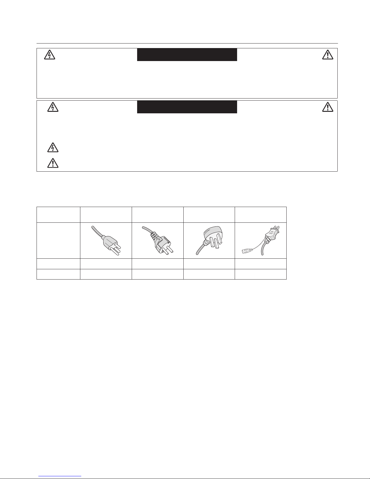
Please use the power cord provided with this display in accordance with the table below. If a power cord is not supplied
with this equipment, please contact your supplier. For all other cases, please use a power cord that matches the AC voltage of the
power outlet and has been approved by and complies with the safety standard of your particular country.
Plug type North America
European
Continental
U.K. Japanese
Plug shape
Region U.S.A./Canada EU (except U.K.) U.K. Japan
Voltage 120* 230 230 100
* When operating the video processor LED-VP1 (D000LE) with its AC 125-240V power supply, use a power supply cord
that matches the power supply voltage of the AC power outlet being used.
NOTE:
This product can only be serviced in the country where it was purchased.
Page 5

English-3
Safety Precautions, Maintenance & Recommended Use
FOR OPTIMUM PERFORMANCE, PLEASE NOTE THE FOLLOWING
WHEN SETTING UP AND USING
THE VIDEO PROCESSOR:
•
DO NOT OPEN THE VIDEO PROCESSOR.
There are no user
serviceable parts inside and opening or removing covers may
expose you to dangerous shock hazards or other risks.
Refer all servicing to qualified service personnel.
• Do not spill any liquids into the cabinet or use your video processor
near water.
• Do not insert objects of any kind into the cabinet slots, as they may
touch dangerous voltage points, which can be harmful or fatal or
may cause electric shock, fire or equipment failure.
• Do not place any heavy objects on the power cord.
Damage to the cord may cause shock or fire.
• Do not place this product on a sloping or unstable cart, stand or
table, as the video processor may fall, causing serious damage to
the video processor.
• The power supply cord you use must have been approved by and
comply with the safety standards of your country.
(Type H05VV-F 3G 1mm
2
should be used in Europe)
• In UK, use a BS-approved power cord with molded plug having a
black (13A) fuse installed for use with this video processor.
• Do not place any objects onto the video processor and do not use
the video processor outdoors.
• Do not bend, crimp or otherwise damage the power cord.
• If video processor is broken, handle with care.
• Do not cover vent on video processor.
• Do not use video processor in high temperature, humid, dusty, or
oily areas.
• Allow adequate ventilation around the video processor, so that heat
can properly dissipate. Do not block ventilated openings or place
the video processor near a radiator or other heat sources.
Do not put anything on top of the video processor.
• The power cable connector is the primary means of detaching
the system from the power supply. The video processor should be
installed close to a power outlet, which is easily accessible.
• Do not move or mount this product by hanging a rope or wire to the
backside handle.
Do not mount or secure this product by using the backside handle.
It may fall and cause personal injury.
• Handle with care when transporting. Save packaging for
transporting.
• Please clean the holes of back cabinet to reject dirt and dust at
least once a year because of set reliability.
• It’s recommended to wipe holes a minimum of once a month.
Connecting to a TV*
• Cable distribution system should be grounded (earthed) in
accordance with ANSI/NFPA 70, the National Electrical Code (NEC),
in particular Section 820.93, Grounding of Outer Conductive Shield
of a Coaxial Cable.
• The screen of the coaxial cable is intended to be connected to earth
in the building installation.
* The product you purchased may not have this feature.
Immediately unplug your video processor from the wall outlet and refer
servicing to qualified service personnel under the following conditions:
• If the video processor has an unusual odor.
• When the power supply cord or plug is damaged.
• If liquid has been spilled, or objects have fallen into the video
processor.
• If the video processor has been exposed to rain or water.
• If the video processor has been dropped or the cabinet damaged.
• If the video processor does not operate normally by following
operating instructions.
• Adjust the video processor's brightness, contrast and sharpness
controls to enhance readability.
Ergonomics
To realize the maximum ergonomic benefits, we recommend the
following:
• Use the preset Color Setting.
• Use non-interlaced signals.
• Do not use primary color blue on a dark background, as it is difficult
to see and may produce eye fatigue due to insufficient contrast.
Cleaning the Cabinet
• Unplug the power supply
• Gently wipe the cabinet with a soft cloth
• To clean the cabinet, dampen the cloth with a neutral detergent and
water, wipe the cabinet and follow with a dry cloth.
NOTE:
DO NOT clean with benzene thinner, alkaline detergent,
alcoholic system detergent, glass cleaner, wax, polish cleaner,
soap powder, or insecticide. Rubber or vinyl should not be in
contact with the cabinet for an extended period of time. These
types of fluids and
materials can cause the paint to deteriorate, crack
or peel.
Page 6

English-4
Contents
The parts supplied with this unit are as follows.
In the rare case that one of these parts is missing or damaged, contact the retailer.
• Power cord (1.8 m USA)
• Power cord (1.8 m EU)
• Signal cable (2 m)
• D-Sub 9-pin cable (1.8 m)
• Setup manual
Page 7
English-5
Parts Name and Functions
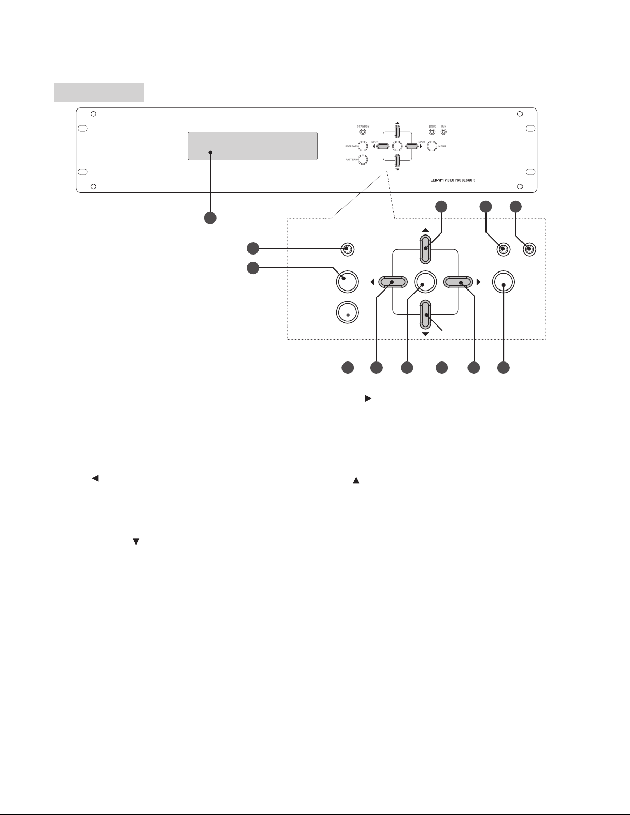
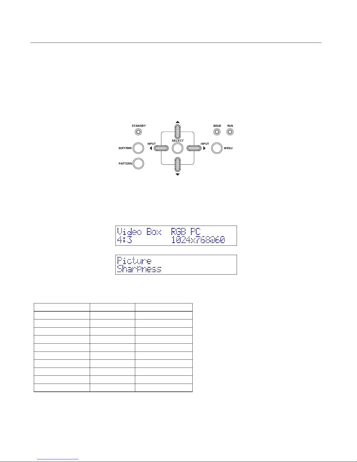
Front panel
7 8
11 129
654
3
2
10
1
MENU
RUN
ISSUE
STANDBY
INPUT INPUT
SELECT
SOFT PWR
PATTERN
1
Display panel
Displays the status, such as the input source and input resolution.
2
SOFT PWR button (power)
Switches the power on and off. Press for longer than 1 second.
3
PATTERN button
Outputs a test video signal.
4
Left(
)/INPUT button
When adjusting the video image, lowers the setting.
When the menu is not being operated, switches the input.
5
SELECT button
Sets the selected item.
6
Down button(
)
When the menu is being operated, moves to the selection item below.
7
Right(
)/INPUT button
When adjusting the video image, raises the setting.
When the menu is not being operated, switches the input.
8
MENU button
When the menu is not displayed on the display panel, displays the menu control. When
the menu is displayed, moves to the level above in the menu display. If there is no level
above, closes the menu.
9
Up(
) button
When the menu is being operated, moves to the selection item above.
0
STANDBY lamp
Lights during standby (orange).
!
ISSUE lamp (error)
Lights when an error occurs (red).
@
RUN lamp
Lights during operation (blue).
Page 8
English-6
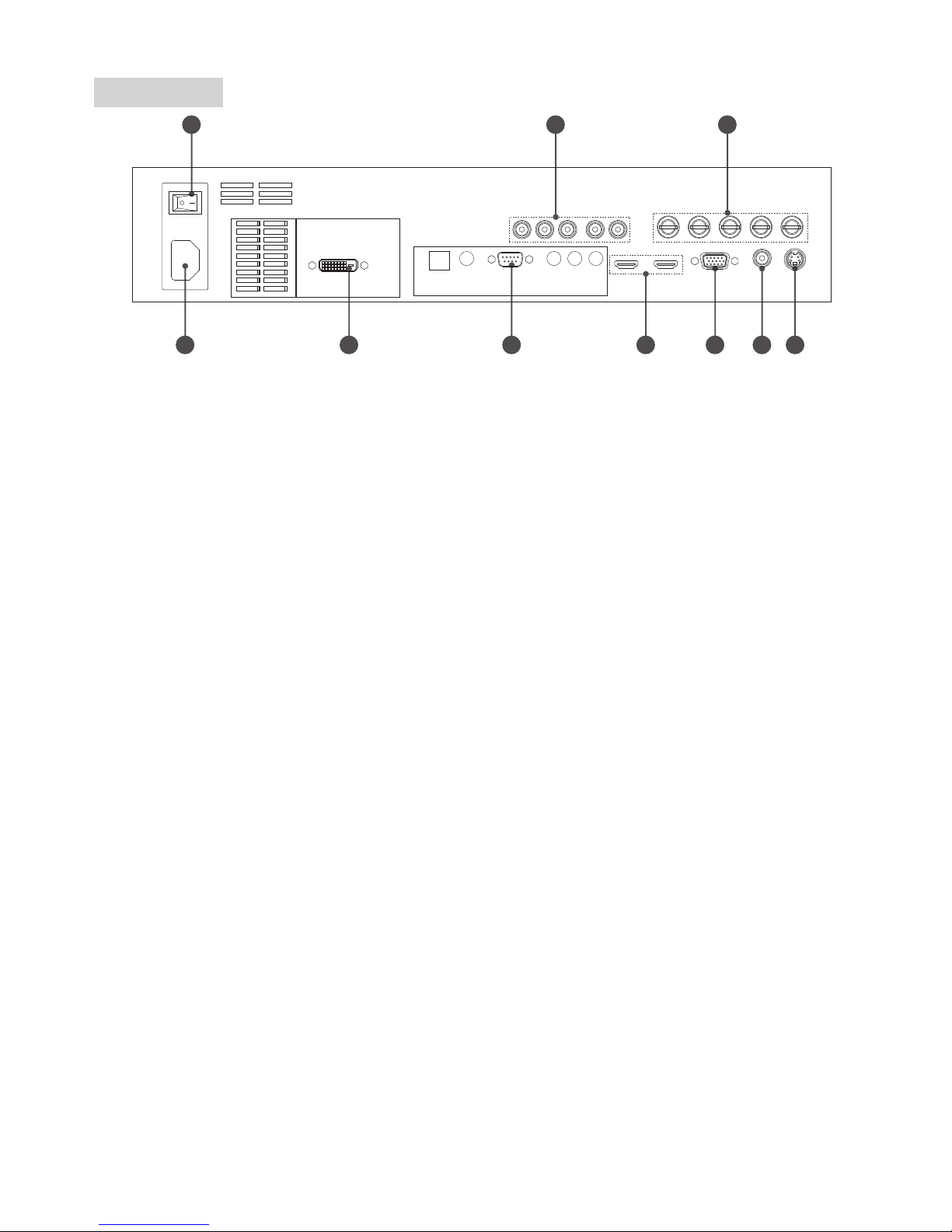
Rear panel
2 3 4
56789
101
I II
1
Power connector (IEC-3)
Connects the power cord.
2
Main power switch (AC)
Switches the main power on and off.
3
HD1 input (RCA)
Connects to an analog RGB or component video output device.
4
HD2 input (BNC)
Connects to an analog RGB or component video output device.
5
S-Video input (mini-DIN 4-pin)
Connects to an S-Video output device.
6
Video input (RCA)
Connects to a composite video output device.
7
HD3 input (mini D-Sub 15-pin)
Connects to an analog RGB or component video output device.
8
HDMI input (HDMI)
This is a digital video input.
9
Control input (D-Sub 9-pin)
The unit can be controlled with RS-232C.
0
DVI output (DVI-D)
This is a digital video output.
Page 9

English-7
Connections
Connecting an External Device
• To protect the device, switch off the power before connecting it.
• When connecting devices, follow the instructions in their user manuals.
Connecting the Power
NOTE :
• Connect the power cord to the unit before connecting it to the power outlet.
1. Insert one end of the power cord into the unit's power input connector.
Insert the cord fully and securely.
2. Connect the power plug to a commercial power source outlet.
WARNING
• Do not use with a power voltage other than the indicated voltage. Doing so may cause a fire or electric shock.
• Use a power cord appropriate for your region if the power cord included is not compatible with your region.
• If the power cord has a ground wire, always be sure to ground it. When disconnecting the ground, be sure to disconnect the power plug from the outlet before
removing the ground. Also, make sure that the ground wire of the power plug does not enter or touch the power outlet. Otherwise, a fire or electric shock may result.
• The power cord supplied with the unit is for use with this product only. To ensure safety, do not use it with other devices.
NOTE :
• This socket-outlet shall be installed the equipment and shall be easily accessible.
Page 10
English-8
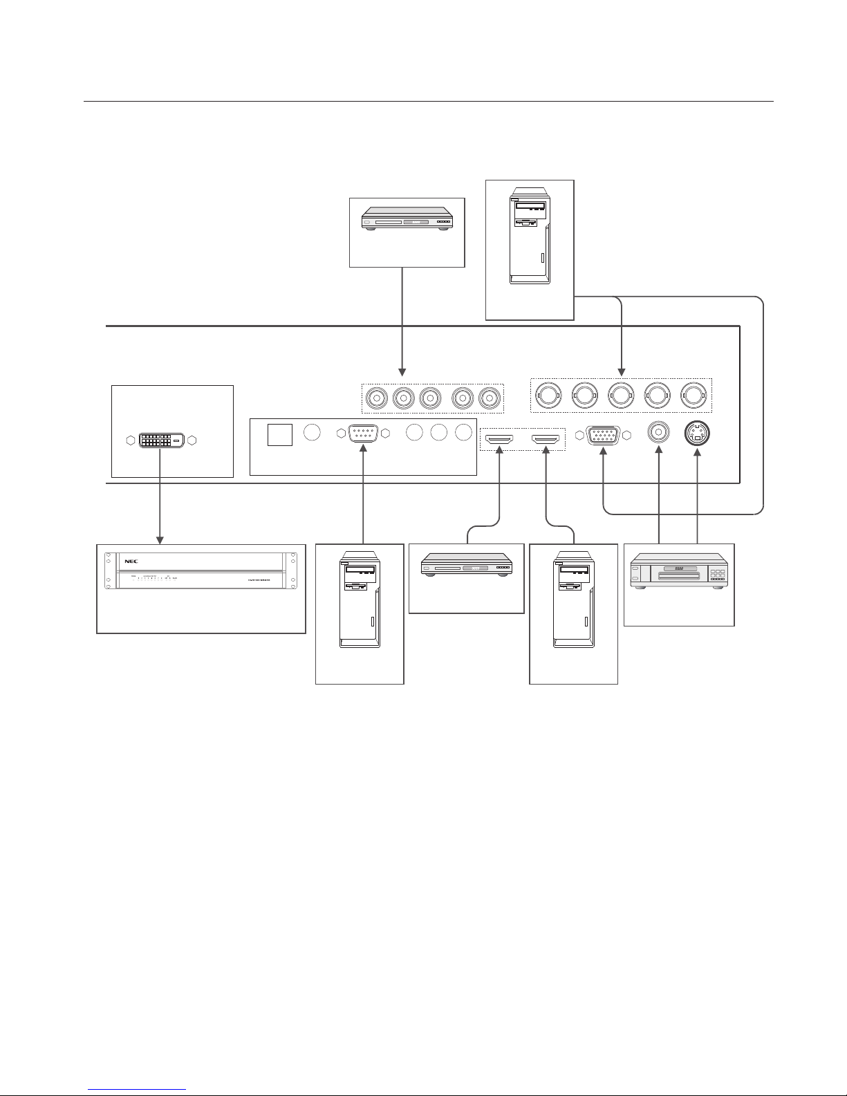
Connection and setting
Before connecting
• Before connecting, switch off the power of the unit, the device to be connected to the unit, and any other peripheral devices.
• Refer to the user manuals of all the devices.
Computer
(analog output)
Computer
(digital output)
Computer
(RS-232C)
Video distributor
(LED-VD1)
DVD player
(component output)
VCR
(video/S-video)
DVD player
(HDMI output)
Connecting to digital devices
When connecting the unit to a computer that has a DVI connector, use a DVI/HDMI conversion cable.
* When purchasing a commercially available conversion adapter or cable, select one that matches the shape of the connector on the computer that you
want to connect.
* Some computers may take some time to display the video.
* When using a signal conversion adapter, connect it on the computer side. The screen may not be displayed if the resolution is low.
Connecting to devices with a HDMI output connector
This unit can be connected to devices such as DVD players that have a HDMI output. For details, see the user manual of
the DVD player or other device.
This unit does not support audio.
Page 11
English-9
Basic Operation
1. Power
1.1 Turning on the power
(1) Turn on the main power (AC) switch.
(2) The RUN lamp lights up (blue). After a short time, the RUN lamp turns off and the STANDBY lamp (STANDBY) lights up
(orange) (indicates the standby status).
(3) Press the SOFT PWR button until the STANDBY lamp turns off.
The power status and LED display are described below.
Standby : STANDBY lamp = on (orange), RUN lamp = off
Operating : STANDBY lamp = off, RUN lamp = on (blue)
1.2 Turning off the power
(1) Press the SOFT PWR button until "Good Bye..." appears on the display panel.
(2) The unit goes into standby.
2. Display panel
(1) Input source and input signal are displayed.
(2) Control menu is displayed. You can switch the input source or adjust the video image.
3. Operations
3.1 Switching the input
The input sources and connector names displayed on the display panel correspond to the items in the following table.
Display
Connector name
Corresponding signal
Composite Video input Composite video signal
S-Video S-Video input S-Video signal
Component RCA HD1 input Analog component signal
Component BNC HD2 input Analog component signal
Component PC HD3 input Analog component signal
RGB RCA HD1 input Analog RGB signal
RGB BNC HD2 input Analog RGB signal
RGB PC HD3 input Analog RGB signal
HDMI 1 HDMI - I input HDMI/DVI-D signal
HDMI 2 HDMI - II input HDMI/DVI-D signal
Page 12
English-10
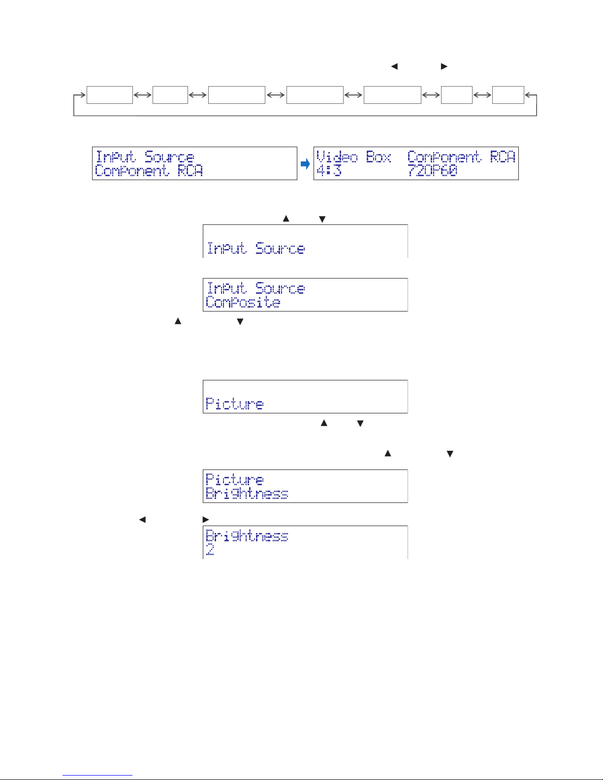
(1) Switching the input with the INPUT button
If the input source and input resolution are not displayed, switch the input with the
INPUT
button or
INPUT
button.
To select analog RGB input, perform the operation in item (2).
Composite S-Video Component PC
Component BNCComponent RCA
HDMI1 HDMI2
The input source is displayed on the display panel, and then the display returns automatically to the input source and input
resolution display.
(2) Switching the input from the menu
Press the MENU button.
If Picture is displayed, switch to Input Source with the
(up) or (down) button.
Press the SELECT button to display the current input source on the display panel.
Switch the input with the (up) button or (down) button and set with the SELECT button.
3.2 Video image adjustment
You can adjust the Brightness, Contrast, Color, Tint and Sharpness.
(1) Press the MENU button to display the menu.
If Input Source is displayed, switch to Picture with the up button (up) or (down) button.
Press the SELECT button.
(2) Select the item to set from brightness, contrast, color, tint and sharpness with the
(up) button or (down) button and set
with the SELECT button.
(3) Adjust with the (left) button or (right) button.
(4) Press the MENU button to return to the previous level and close the menu.
Page 13
English-11
Troubleshooting
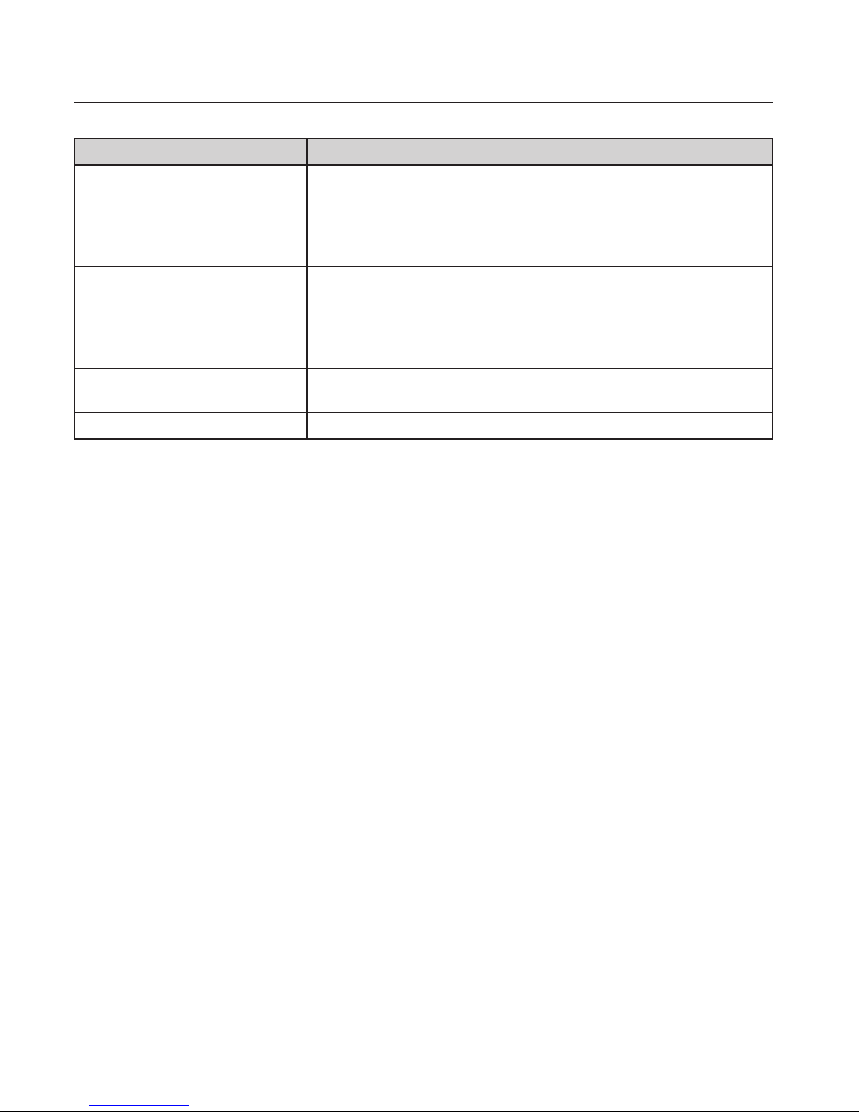
Check the troubleshooting guide below.
Symptom Causes and countermeasures
The power does not turn on. The SOFT PWR button must be held down to turn on the power.
Keep pressing the SOFT PWR button until the STANDBY lamp turns off.
The component signal is not displayed. The component signal is not displayed when the input source is an RGB input.
Make sure that the input is Component RCA, Component BNC or
Component PC.
The RGB signal is not displayed. The RGB signal is not displayed properly when the input source is a component input.
Make sure that the input is RGB RCA, RGB BNC or RGB PC.
The command communication does not operate. • Check that the computer's COM port is connected to the unit.
• Check the computer's COM port number.
• Check the software's communication settings.
The size of the video display is inappropriate.
The position of the video display is inappropriate.
A communication command may be setting the display size and display position.
Check the settings.
The error lamp (ISSUE) is lit. The unit may be malfunctioning. Contact the retailer.
Page 14
English-12
Appendix
Specifications
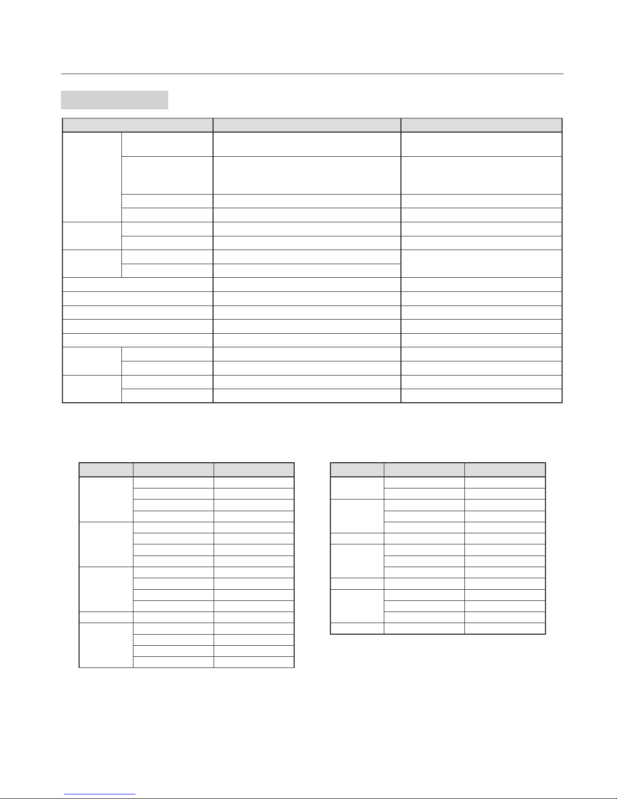
Product name LED-VP1 Remarks
Input
(*1)
Digital Video HDMI (2 connectors)
Can be connected to a DVI-D device with a
conversion cable.
Analog
(*2)
RGB/Component video
HD1: RCA x 5
HD2: BNC x 5
HD3: Mini D-Sub 15-pin
Composite video RCA
S-Video Mini-DIN 4-pin
Output
Interface
DVI-D
Output resolution
1024 x 768 at 60 Hz Output resolution is fixed.
Control
Interface
D-Sub 9-pin (male)
Use the supplied RS-232C cable.
Specifications Compliant with RS-232C
Power input 100 V to 240 V AC, 50/60 Hz
Power consumption 16 W
Complied Regulatory and Guidelines cTUVus, TUV-GS, FCC(Class-A), CE(Class-A)
Dimension 480 (W) x 94.1 (H) x 340 (D) mm
Weight 3.2kg(7.1lbs)
Operating
Environment
Temperature 5˚C to 35˚C
Humidity 10% to 90% (without condensation)
Storage
Environment
Temperature 0˚C to 50˚C
Humidity 10% to 90% (without condensation)
*1: Refer to the following timings and formats.
*2: Supports RGB and Component video signals by switching the input source.
NOTE: Technical specifications are subject to change without notice.
Digital/Analog (RGB) input signal support timing
Resolution Horizontal frequency Vertical frequency
640 x 480
31.469 kHz 60 Hz
37.861 kHz 72 Hz
37.500 kHz 75 Hz
43.269 kHz 85 Hz
800 x 600
37.879 kHz 60 Hz
48.077 kHz 72 Hz
46.875 kHz 75 Hz
53.674 kHz 85 Hz
1024 x 768
48.363 kHz 60 Hz
56.476 kHz 70 Hz
60.023 kHz 75 Hz
68.677 kHz 85 Hz
1152 x 864 67.500 kHz 75 Hz
1280 x 768
47.396 kHz 60 Hz
47.776 kHz 60 Hz
60.289 kHz 75 Hz
68.633 kHz 85 Hz
Resolution Horizontal frequency Vertical frequency
1280 x 960
60.000 kHz 60 Hz
85.938 kHz 85 Hz
1280 x 1024
63.981 kHz 60 Hz
79.976 kHz 75 Hz
91.146 kHz 85 Hz
1360 x 768 47.712 kHz 60 Hz
1400 x 1050
64.744 kHz 60 Hz
65.317 kHz 60 Hz
82.278 kHz 75 Hz
1600 x 1200 75.000 kHz 60 Hz
1920 x 1080
56.250 kHz 50 Hz
67.433 kHz 59.94 Hz
67.500 kHz 60 Hz
1920 x 1200 74.038 kHz 60 Hz
Component video format
1080@50p/60p, 1080@50i/60i, 720@50p/60p, 576p, 480p, 576i, 480i
Composite video/S-Video format
NTSC-M, NTSC4.43, PAL-B/G, PAL-M, PAL-N, PAL60, SECAM
Page 15
English-13
Communication command specifications
Baud rate 19200 bps
Data bits 8 bit
Parity None
Stop bit
1 bit
Flow control None
Commands
(1) Power control
Power on 6Fh 6Eh 0Dh
Power off 6Fh 66h 66h 0Dh
(2) Switching the input
Composite video 73h 73h 72h 63h 20h 30h 0Dh
S-Video 73h 73h 72h 63h 20h 31h 0Dh
Component video (RCA)
73h 73h 72h 63h 20h 32h 0Dh
Component video (BNC)
73h 73h 72h 63h 20h 33h 0Dh
Component video (VGA)
73h 73h 72h 63h 20h 34h 0Dh
RGBHV (RCA) 73h 73h 72h 63h 20h 35h 0Dh
RGBHV (BNC) 73h 73h 72h 63h 20h 36h 0Dh
RGBHV (VGA) 73h 73h 72h 63h 20h 37h 0Dh
HDMI 1 73h 73h 72h 63h 20h 38h 0Dh
HDMI 2 73h 73h 72h 63h 20h 39h 0Dh
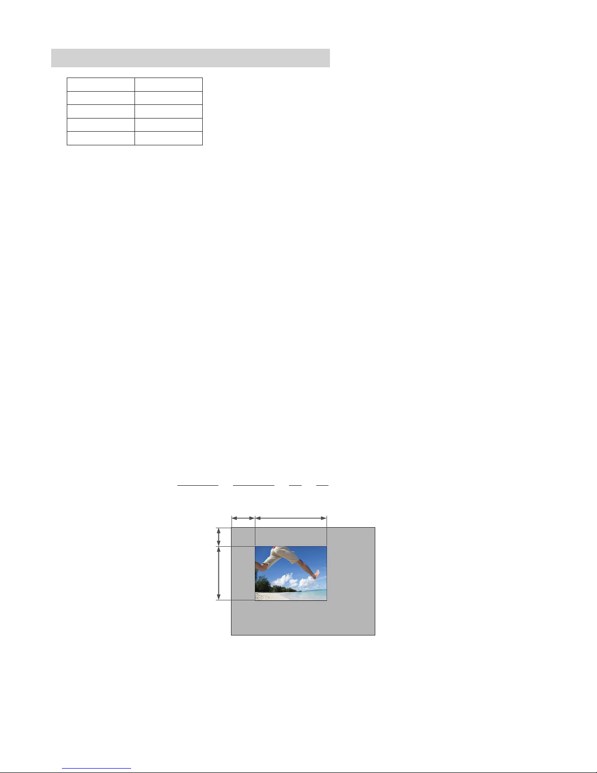
(3) Setting the video display size and position
Setting commands
6Fh 73h 69h 7Ah 65h 20h 31h 20h [H.size] 20h [V.size] 20h [H.pos] 20h [V.pos] 0Dh
H.size, V.size, H.pos and V.pos are expressed with ASCII codes.
Example: When the display size is 320x240 and the display start position is (0,0),
H.size = 33h, 32h, 30h (=320)
V.size = 32h, 34h, 30h (=240)
H.pos = 30h (=0)
V.pos = 30h (=0)
the above are expressed with ASCII codes. The send commands are as follows.
6Fh 73h 69h 7Ah 65h 20h 31h 20h 33h 32h 30h 20h 32h 34h 30h 20h 30h 20h 30h 0Dh
H.size V.size H.pos V.pos
H.pos
(0,0)
(1023,767)
H.size
V.pos
V.size
Page 16
English-14
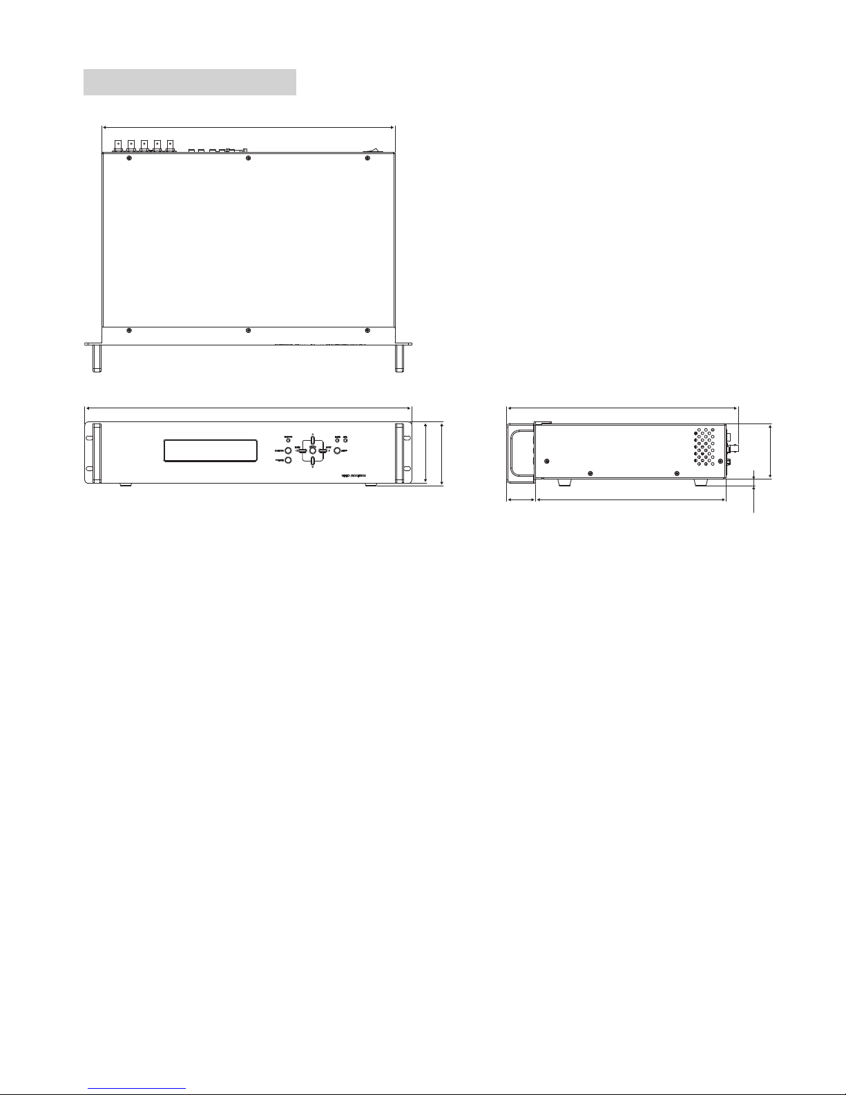
Dimensional Drawing
431.1
480
340
42.5 280
90
94.1
81.5
10.3
Unit: mm
Page 17

English-15
Manufacturer’s Recycling and Energy Information
NEC DISPLAY SOLUTIONS is strongly committed to environmental protection and sees recycling as one of the company’s top
priorities in trying to minimize the burden placed on the environment. We are engaged in developing environmentallyfriendly
products, and always strive to help define and comply with the latest independent standards from agencies such as ISO (International
Organisation for Standardization) and TCO (Swedish Trades Union).
Disposing of your old NEC product
The aim of recycling is to gain an environmental benefit by means of re-use, upgrading, reconditioning or reclamation of material.
Dedicated recycling sites ensure that environmentally harmful components are properly handled and securely disposed. To ensure
the best recycling of our products,
NEC DISPLAY SOLUTIONS offers a variety of recycling procedures
and gives advice on how
to handle the product in an environmentally sensitive way, once it has reached the end of its life.
All required information concerning the disposal of the product and country-specific information on recycling facilities can be found
on our following websites:
http://www.nec-display-solutions.com/greencompany/
(in Europe),
http://www.nec-display.com
(in Japan) or
http://www.necdisplay.com
(in USA).
WEEE Mark (European Directive 2002/96/EC)
Within the European Union
EU-wide legislation, as implemented in each Member State, requires that waste electrical and electronic
products carrying the mark (left) must be disposed of separately from normal household waste. This includes
monitors and electrical accessories, such as signal cables or power cords. When you need to dispose of your
NEC display products, please follow the guidance of your local authority, or ask the shop where you
purchased the product, or if applicable, follow any agreements made between yourself and NEC.
The mark on electrical and electronic products only applies to the current European Union Member States.
Outside the European Union
If you wish to dispose of used electrical and electronic products outside the European Union, please contact your local
authority so as to comply with the correct disposal method.
 Loading...