

Page 1
MultiSync® LCD2180UX
TM
Page 2

Index
Warning .................................................................................................................... 1
Contents ................................................................................................................. 2
Quick Start ............................................................................................................. 3
Controls ...................................................................................................................7
Long Cable Compensation Adjustment ........................................................... 11
Recommended Use ............................................................................................... 12
Specifications ...................................................................................................... 14
Features .................................................................................................................15
Troubleshooting ................................................................................................... 17
References .............................................................................................................18
Limited Warranty ................................................................................................. 19
TCO’99 .................................................................................................................... 20
TCO’03 .................................................................................................................... 22
Manufacturer’s Recycling and Energy Information .................................... 23
Avertissement ..................................................................................................... 25
Contenu ................................................................................................................. 26
Mise en marche rapide ...................................................................................... 27
Commandes ........................................................................................................... 31
Réglage de la compensation de câble long .................................................. 35
Usage recommandé ............................................................................................ 36
Fiche technique ................................................................................................... 38
Fonctions .............................................................................................................. 39
Dépannage ............................................................................................................ 41
Références ........................................................................................................... 42
Garantie limitée .................................................................................................. 43
TCO’99 .................................................................................................................... 44
TCO’03 ....................................................................................................................46
Informations du fabricant relatives au recylage et aux économies d’énergie ...
47
Appendix ............................................................................................................... 49
Annexe .................................................................................................................. 53
Page 3

WARNING
TO PREVENT FIRE OR SHOCK HAZARDS, DO NOT EXPOSE THIS UNIT TO RAIN OR MOISTURE. ALSO, DO NOT USE
THIS UNIT'S POLARIZED PLUG WITH AN EXTENSION CORD RECEPTACLE OR OTHER OUTLETS UNLESS THE PRONGS
CAN BE FULLY INSERTED.
REFRAIN FROM OPENING THE CABINET AS THERE ARE HIGH VOLTAGE COMPONENTS INSIDE. REFER SERVICING
TO QUALIFIED SERVICE PERSONNEL.
CAUTION
CAUTION: TO REDUCE THE RISK OF ELECTRIC SHOCK, MAKE SURE POWER CORD IS UNPLUGGED FROM
WALL SOCKET. TO FULLY DISENGAGE THE POWER TO THE UNIT, PLEASE DISCONNECT THE POWER
CORD FROM THE AC OUTLET. DO NOT REMOVE COVER (OR BACK). NO USER SERVICEABLE PARTS
INSIDE. REFER SERVICING TO QUALIFIED SERVICE PERSONNEL.
This
symbol warns user that uninsulated voltage within the unit may have sufficient magnitude to cause
electric shock. Therefore, it is dangerous to make any kind of contact with any part inside this unit.
This symbol alerts the user that important literature concerning the operation and maintenance of this
unit has been included. Therefore, it should be read carefully in order to avoid any problems.
Canadian Department of Communications Compliance Statement
DOC: This Class B digital apparatus meets all requirements of the Canadian
Interference-Causing Equipment Regulations.
C-UL: Bears the C-UL Mark and is in compliance with Canadian Safety Regulations
according to
CAN/CSA C22.2 No. 60950.
FCC Information
1.
Use the attached specified cables with the
so as not to interfere with radio and television reception.
(1)
Please use the supplied power cord or equivalent to ensure FCC compliance.
(2) Please use the supplied shielded video signal cable, 15-pin mini D-SUB to
DVI-A cable or DVI-D to DVI-D cable.
Use of other cables and adapters may cause interference with radio and
television reception.
2.
This equipment has been tested and found to comply with the limits for a Class B digital
device, pursuant to part 15 of the FCC Rules. These limits are designed to provide
reasonable protection against harmful interference in a residential installation. This
equipment generates, uses, and can radiate radio frequency energy, and, if not installed
and used in accordance with the instructions, may cause harmful interference to radio
communications. However, there is no guarantee that interference will not occur in a
particular installation. If this equipment does cause harmful interference to radio or
television reception, which can be determined by turning the equipment off and on, the user
is encouraged to try to correct the interference by one or more of the following measures:
• Reorient or relocate the receiving antenna.
• Increase the separation between the equipment and receiver.
• Connect the equipment into an outlet on a circuit different from that to which the receiver
is connected.
• Consult your dealer or an experienced radio/TV technician for help.
MultiSync LCD2180UXTM (L213E9) color monitor
If necessary, the user should contact the dealer or an experienced radio/television technician
for additional suggestions. The user may find the following booklet, prepared by the Federal
Communications Commission, helpful: ”How to Identify and Resolve Radio-TV Interference
Problems.“ This booklet is available from the U.S. Government Printing Office, Washington,
D.C., 20402, Stock No. 004-000-00345-4.
1
LCD2180UXManual1020.p65 10/21/03, 9:10 AM1
Page 4
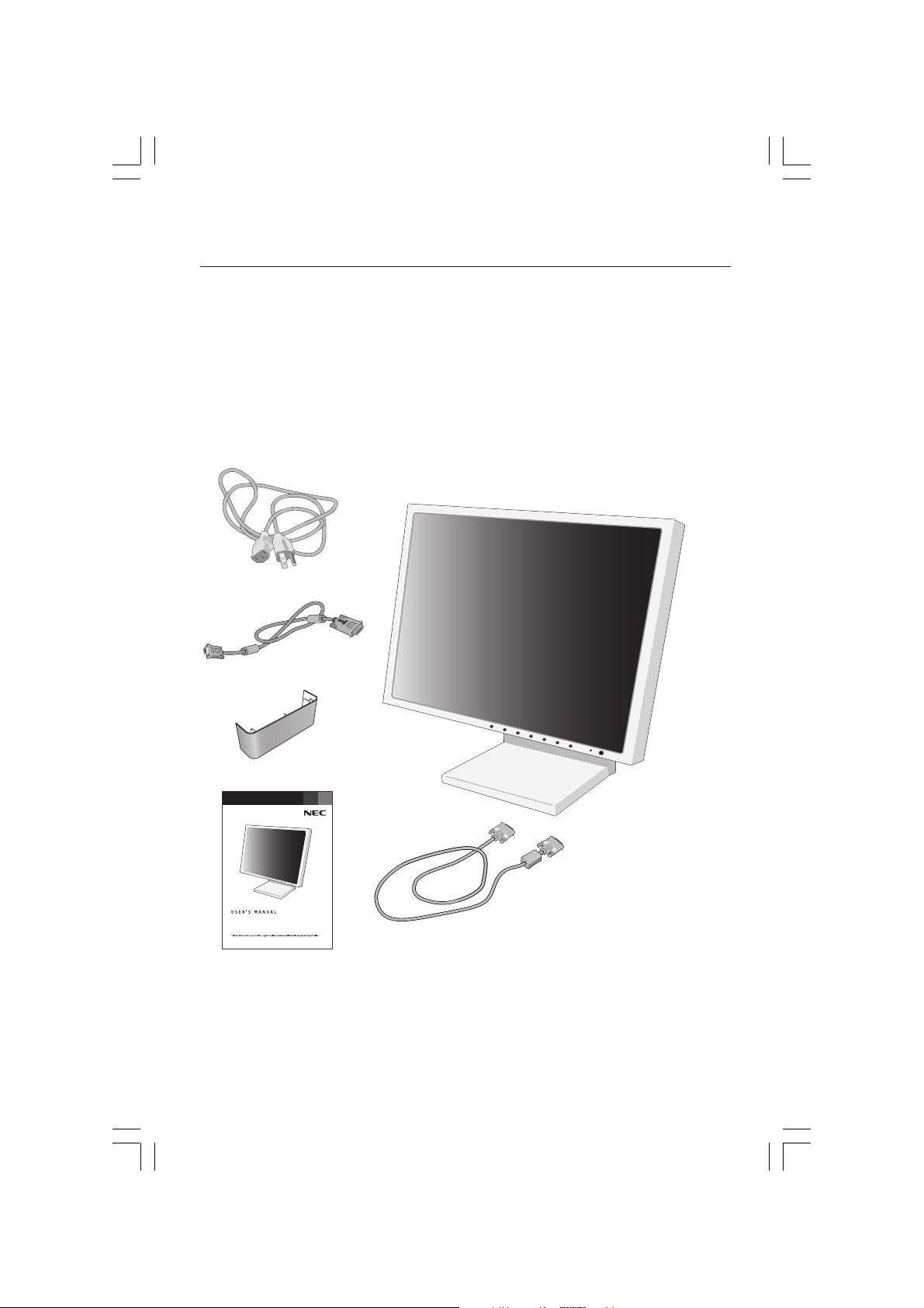
Contents
Your new NEC MultiSync® LCD monitor box* should contain the
following:
• MultiSync LCD2180UX™ monitor with tilt/swivel/pivot/adjustable stand
• Power Cord
• Video Signal Cable (15-pin mini D-SUB male to DVI-A)
• Video Signal Cable (DVI-D to DVI-D cable)
• User’s Manual
• Cable Cover
Power Cord
15-pin mini D-SUB
male to DVI-A
Cable Cover
TM
®
MultiSync
LCD2180UX
DVI-D to DVI-D cable
User’s Manual
*Remember to save your original box and packing material to transport or ship the monitor.
2
LCD2180UXManual1020.p65 10/21/03, 9:10 AM2
Page 5
Quick Start
To attach the MultiSync® LCD monitor to your system, follow these instructions:
1. Turn off the power to your computer.
2. For the PC or MAC with DVI digital output: Connect the DVI-D signal cable to the connector of the
display card in your system (Figure A.1). Tighten all screws.
For the PC with Analog output: Connect the 15-pin mini D-SUB to DVI-A signal cable to the
connector of the display card in your system (Figure A.2).
For the MAC: Connect the MultiSync Macintosh cable adapter to the computer, then attach the
15-pin mini D-SUB signal cable to the MultiSync Macintosh cable adapter (Figure B.1).
NOTE: Some Macintosh systems do not require a Macintosh cable adapter.
NOTE: To obtain the MultiSync Macintosh cable adapter call NEC-Mitsubishi Electronics Display of
America, Inc. at (800) 632-4662.
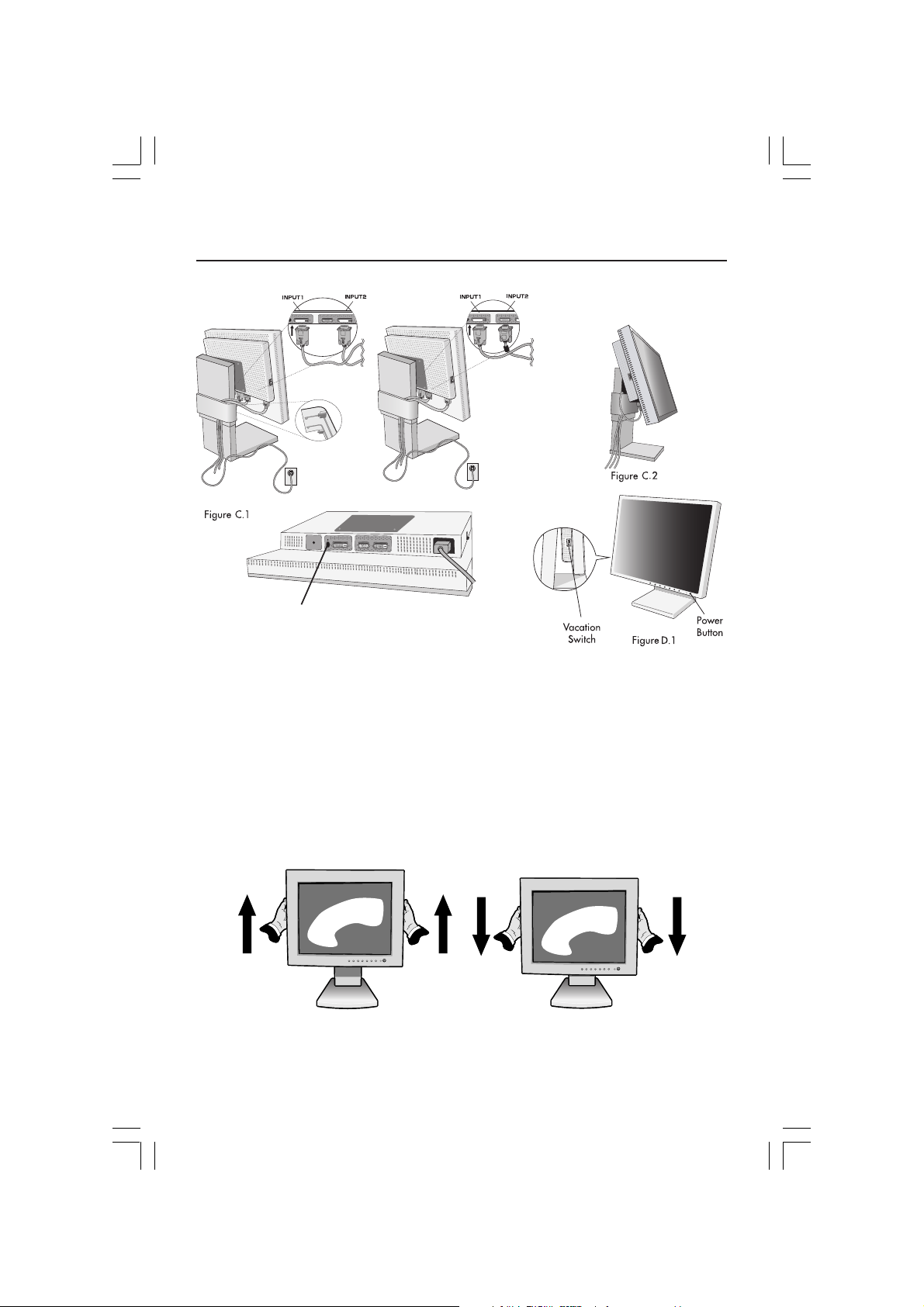
3. Connect the 15-pin mini D-SUB to DVI-A signal cable to the connector on the back of the monitor
into Input1 or the DVI-D signal cable to Input2 (Figure C.1).
NOTE: Incorrect cable connections may result in irregular operation, damage display
quality/components of LCD module and/or shorten the module’s life.
Gather the cables and attach them to the stand with the cable cover. The cable cover can be
attached on the front or the back of the stand
interfere with operation of the stand (tilt, raise, lower and screen rotation).
4. Connect one end of the power cord to the AC inlet on the back of the monitor and the
other end to the power outlet (Figure C.1).
NOTE: If you use this monitor at AC125-240V, please refer to Recommended Use section of this
manual for proper selection of AC power cord.
5. The Vacation Switch on the left side of the monitor must be turned on. Turn on the monitor with the
front power button (Figure D.1) and the computer.
NOTE:
The Vacation Switch is a true on/off switch. If this switch is on the OFF position, the
monitor cannot be turned on using the front button. DO NOT switch on/off repeatedly.
NOTE: For the MAC with digital output: before turning on the MAC, the DVI Input mode must
be set to DIGITAL in DVI SELECTION of OSM by pressing SELECT button then CONTROL
button when the DVI signal cable is connected to the DVI-I connector (Input1) of the
monitor. Otherwise the MAC may not turn on.
6. No-touch auto adjust automatically adjusts the monitor to optimal settings upon initial setup for
most timings. For further adjustments, use the following OSM® controls:
• Auto Contrast (Analog input only)
• Auto Adjust (Analog input only)
Refer to the Controls section of this User’s Manual for a full description of these OSM controls.
NOTE: For download information on the Windows® 95/98/Me/2000/XP INF file for your MultiSync
LCD2180UX monitor, refer to the References section of this User’s Manual.
NOTE: If you have any problems, please refer to the Troubleshooting section of this User’s Manual.
(Figure C.1, C.2)
. Please check that cables do not
Figure A.1
LCD2180UXManual1020.p65 10/21/03, 9:10 AM3
Figure A.2
3
Macintosh
Adapter
Figure B.1
Macintosh Cable Adapter (not
included) Note: Some Macintosh
systems do not require a Macintosh
Cable Adapter
Page 6
Quick Start –continued
NEC optional product attachment. Do not
use this connector unless specified.
Raise and Lower Monitor Screen
The monitor may be raised or lowered in either Portrait or Landscape mode.
To raise or lower screen, place hands on each side of the monitor and lift or
lower to the desired height (Figure RL.1).
NOTE: Handle with care when raising or lowering the monitor screen.
Figure RL.1
4
LCD2180UXManual1020.p65 10/21/03, 9:10 AM4
Page 7

Quick Start –continued
Screen Rotation
Before rotating, the screen must be raised to the highest level to avoid knocking
the screen on the desk or pinching your fingers. To raise the screen, place hands
on each side of the monitor and lift up to the highest position (Figure RL.1).
To rotate screen, place hands on each side of the monitor screen and turn
clockwise from Landscape to Portrait or counter-clockwise from Portrait to
Landscape (Figure R.1).
To toggle the orientation of the OSM menu between Landscape and Portrait
modes, refer to the “Controls” section, “OSM Rotation” function.
Figure R.1
Tilt
Grasp top and bottom sides of the monitor
screen with your hands and adjust the tilt
as desired (Figure TS.1).
NOTE: Handle with care when tilting the monitor screen.
LCD2180UXManual1020.p65 10/21/03, 9:10 AM5
Swivel
Grasp both sides of the monitor screen
with your hands and adjust the swivel
as desired (Figure TS.2).
5
Page 8
Quick Start –continued
Remove Monitor Stand for Mounting
To prepare the monitor for alternate mounting purposes:
1. Disconnect all cables.
2. Place hands on each side of the monitor and lift up to the highest position.
3.
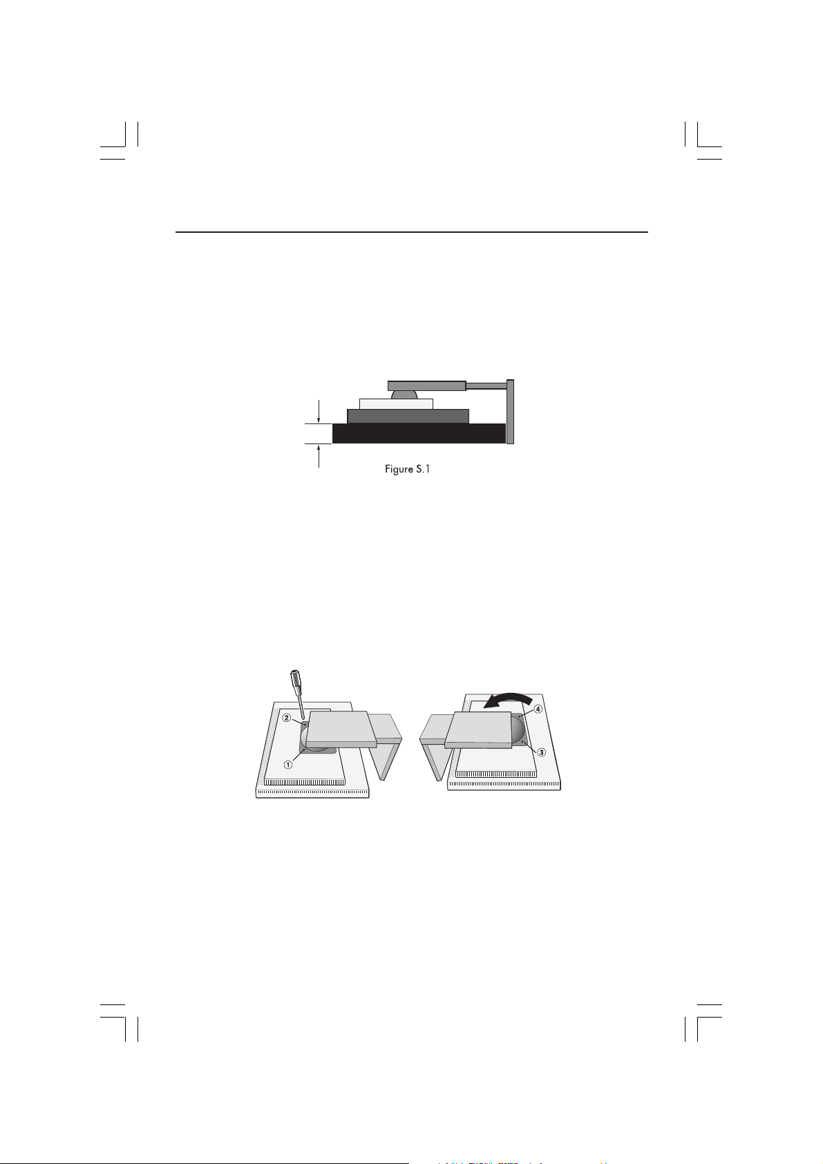
Place monitor face down on a nonabrasive surface. (Place the screen on a 29
mm platform so that the stand is parallel with the surface.) (Figure S.1)
29mm
4. Remove the two top screws connecting the monitor to the stand (Figure
S.2). Turn the stand to 180˚ counterclockwise (you will hear two clicks).
Remove the screws from the bottom (Figure S.3) and lift off the stand. The
monitor is now ready for mounting in an alternate manner.
5. Reverse this process to reattach stand: tighten the two bottom screws, turn
stand 180˚ counterclockwise (you will hear two clicks), and tighten two top
screws.
NOTE: Use only VESA-compatible alternative mounting method. (100mm pitch)
NOTE: Handle with care when removing monitor stand.
Figure S.2 and Figure S.3
Caution: Use the original screws (4 pcs) when mounting to avoid damage to the monitor and stand. To
LCD2180UXManual1020.p65 10/21/03, 9:10 AM6
fulfil the safety requirements the monitor must be mounted to an arm which guaranties the
necessary stability under consideration of the weight of the monitor. The LCD monitor should
only be used with an approved arm
(e.g. GS mark).
6
Page 9
Controls
OSM® (On-Screen Manager) control buttons on the front of the
monitor function as follows:
To access OSM menu, press any of the control buttons ( , , –, +).
To change signal input, press the SELECT button.
NOTE:
OSM must be closed in order to change signal input.
Menu
EXIT Exits the OSM controls.
CONTROL / Moves the highlighted area left/right to select control menus.
ADJUST
SELECT Activates the Auto Adjust function. Enter the OSM controls.
RESET Resets the highlighted control menu to the factory setting.
–/+
Exits to the OSM main menu.
Moves the highlighted area up/down to select one of the controls.
Moves the bar left/right to increase or decrease the adjustment.
Enter the OSM sub menu.
NOTE: When RESET is pressed in the main and sub-menu, a warning window
allowing you to cancel the RESET function by pressing the EXIT button.
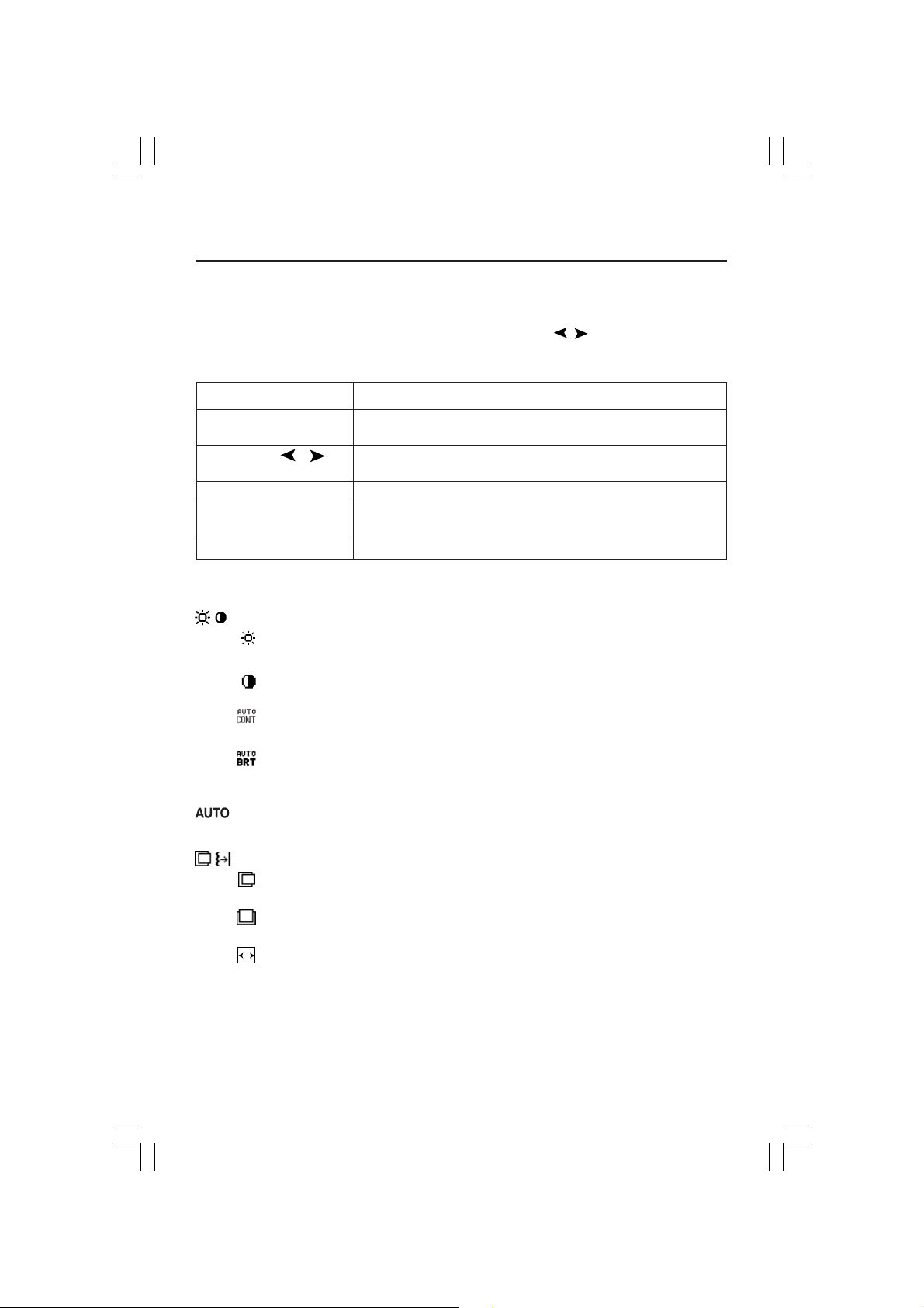
Brightness/Contrast Controls
BRIGHTNESS
Adjusts the overall image and background screen brightness.
CONTRAST
Adjusts the image brightness in relation to the background.
AUTO CONTRAST (Analog input only)
Adjusts the image displayed for non-standard video inputs.
AUTO BRIGHTNESS
This function adjusts the brightness automatically for the best CONTRAST and
BRIGHTNESS setting based on the white display area.
Auto Adjust (Analog input only)
Automatically adjusts the Image Position and H. Size settings and Fine settings.
Image Controls
LEFT / RIGHT
Controls Horizontal Image Position within the display area of the LCD.
DOWN / UP
Controls Vertical Image Position within the display area of the LCD.
H.SIZE (Analog input only)
Adjusts the horizontal size by increasing or decreasing this setting.
If the “AUTO Adjust function” does not give you a satisfactory picture setting,
a further tuning can be performed using the “H.Size” function (dot clock). For
this a Moiré test pattern could be used. This function may alter the
will appear
LCD2180UXManual1020.p65 10/21/03, 9:10 AM7
7
Page 10

Controls –continued
width of the picture. Use left/Right Menu to center the image on the screen. If
the H.Size is wrongly calibrated, the result would look like on the left drawing.
The image should be homogeneous.
Wrong
FINE
(Analog input only)
Improves focus, clarity and image stability by increasing or decreasing this setting.
If the “Auto Adjust function” and the “H.Size” function do not give you a
satisfactory picture setting, a
function. It improves focus, clarity and image stability by increasing or decreasing this setting.
For this a
calibrated, the result would look like on the left drawing. The image should be
homogeneous.
AccuColor
AccuColor® Control Systems: Six color presets select the desired color setting
(sRGB, NATIVE and PROGRAMMABLE color presets are standard and cannot
be changed). Color temperature increases or decreases, in each preset.
R,Y,G,C,B,M,S: Increases or decreases Red, Yellow, Green, Cyan, Blue,
Magenta and Saturation depending upon which is selected. The change in
color will appear on screen and the direction (increase or decrease) will be
shown by the color bars. NATIVE:
that is unadjustable. PROGRAMMABLE: The colour temperature and tone
that were set up with the downloaded application software are reflected.
Tools 1
SHARPNESS:
It is continuously adjustable to get distinct image or soft one as you prefer, and set
independently by different timings.
The number of adjustment steps is different depending on whether EXPANSION
Mode is OFF, FULL or ASPECT (1600 x 1200 is OFF Mode).
EXPANSION MODE: Sets the zoom method.
Moiré test pattern could be used. If the Fine value is wrongly
Wrong
®
Control Systems
This function is digitally capable to keep crisp image at any timings.
FULL: The image is expanded to
ASPECT: The image is expanded without changing the aspect ratio.
OFF: The image is not expanded.
fine tuning can be performed using the “Fine”
Original color presented by the LCD panel
1600 x 1200
Correct
Correct
, regardless of the resolution.
LCD2180UXManual1020.p65 10/21/03, 9:10 AM8
8
Page 11

Controls –continued
CUSTOM (Digital input and Resolution of 1600 x 1200 only): Select one
of nine expansion rates. In this mode the resolution may be low and
there may be blank areas. This mode is for use with special video cards.
VIDEO DETECT: Selects the method of video detection when more than one
computer is connected.
FIRST DETECT: The video input has to be switched to “FIRST DETECT”
mode. When current video input signal is not present, then the monitor
searches for a video signal from the other video input port. If the video
signal is present in the other port, then the monitor switches the video
source input port to the new found video source automatically.
will not look for other video signals while the current video source is present.
LAST DETECT:
mode.
and a new secondary source is supplied to the monitor, then the monitor
will automatically switch to the new video source. When current video
input signal is not present, then the monitor searches for a video signal
from the other video input port. If the video signal is present in the other
port, then the monitor switches the video source input port to the new
found video source automatically.
NONE: The Monitor will not search the other video input port unless the
monitor is turned on.
DVI SELECTION: This function selects the DVI input mode (Input 1). When the DVI
selection has been changed, you must restart your computer.
AUTO: By using the DVI-D to DVI-D cable, the DVI SELECTION is DIGITAL.
By using the D-SUB to DVI-A cable, the DVI SELECTION is ANALOG.
DIGITAL: DVI digital input is available.
ANALOG: DVI analog input is available.
NOTE: For the MAC with digital output: before turning on the MAC, the DVI
Input mode must be set to DIGITAL in DVI SELECTION of OSM by
pressing SELECT button then CONTROL button when the DVI signal cable
is connected to the DVI-I connector (Input1) of the monitor. Otherwise the
MAC may not turn on.
NOTE: Depending on the PC/Video card or video signal cable used, this
function may not operate.
OFF TIMER:
a predetermined amount of time.
Tools 2
LANGUAGE: OSM control menus are available in seven languages.
OSM LEFT/RIGHT: You can choose where you would like the OSM control
image to appear on your screen. Selecting OSM Location allows you to
manually adjust the position of the OSM control menu left or right.
OSM DOWN/UP: You can choose where you would like the OSM control
image to appear on your screen. Selecting OSM Location allows you to
manually adjust the position of the OSM control menu down or up.
The video input has to be switched to the “LAST DETECT”
When the monitor is displaying a signal from the current source
Monitor will automatically power-down when the end user has selected
The monitor
LCD2180UXManual1020.p65 10/21/03, 9:10 AM9
9
Page 12

Controls –continued
OSM TURN OFF: The OSM control menu will stay on as long as it is use. In the
OSM Turn Off submenu, you can select how long the monitor waits after the
last touch of a
120 seconds by 5 second increments.
OSM LOCK OUT: This control completely locks out access to all OSM control
functions. When attempting to activate OSM controls while in the Lock Out
mode, a screen will appear indicating the OSM controls are locked out.
There are two types of OSM LOCK OUT: OSM LOCK OUT with BRIGHTNESS and CONTRAST control: To activate the OSM Lock Out function, press
SELECT, then “+” key and hold down simultaneously. To deactivate the OSM
Lock Out, press SELECT, then “+” key and hold down simultaneously.
BRIGHTNESS and CONTRAST can be adjusted while in the lock out mode.
OSM LOCK OUT with no control: To activate the OSM Lock Out function,
press SELECT, then “>” key and hold down simultaneously. To deactivate the
OSM Lock Out, press SELECT, then “>” key and hold down simultaneously.
No controls can be adjusted while in the lock out mode.
OSM ROTATION: To rotate OSM between Landscape and Portrait modes.
RESOLUTION NOTIFIER: This optimal resolution is 1600 x 1200. If ON is
selected, a message
that the resolution is not at
HOT KEY: You can adjust the brightness and contrast directly. When this
function is set to ON, you can adjust the brightness with “<” or “>”, contrast
with + or – key, while the OSM menu is off.
FACTORY PRESET: Selecting Factory Preset allows you to reset most OSM
control settings back to the factory settings. Individual settings can be reset by
highlighting the control to be reset and pressing the RESET button.
Information
DISPLAY MODE: Provides information about the current resolution display and
technical data including the preset timing being used and the horizontal and
vertical frequencies. Increases or decreases the current resolution.
MONITOR INFO.: Indicates the model and serial numbers of your monitor.
OSM Warning: OSM Warning menus disappear with Exit button.
NO SIGNAL: This function gives a warning when there is no Horizontal or
Vertical Sync. After
signal, the No Signal window will appear.
RESOLUTION NOTIFIER: This function gives a warning of use with optimized
resolution. After power is turned on or when there is a change of input
signal or the video signal doesn’t have proper resolution, the Resolution
Notifier window will open. This function can be disabled in the TOOL menu.
OUT OF RANGE: This function gives a recommendation of the optimized
resolution and refresh rate. After the power is turned on or there is a
change of input signal or the video signal doesn’t have proper timing, the
Out Of Range menu will appear.
NOTE: If “ CHANGE DVI SELECTION” is displayed, switch to DVI SELECTION.
For advanced user menu see “Appendix”.
button to shut off the OSM control menu. The preset choices are 10-
will appear on the screen after 30 seconds, notifying you
power is turned on or when there is a change of input
1600 x 1200
.
LCD2180UXManual1020.p65 10/21/03, 9:10 AM10
10
Page 13
Long Cable Compensation Adjustment
Long Cable Compensation should only be performed when using extended length cables
or to compensate for a low-quality video signal. To perform the long cable compensation
adjustment, follow these six steps:
1.For optimal adjustment, download the “LCD Long Cable Comp Test Pattern” and “Read
Me” file at www.necmitsubishi.com and display the test pattern during this adjustment.
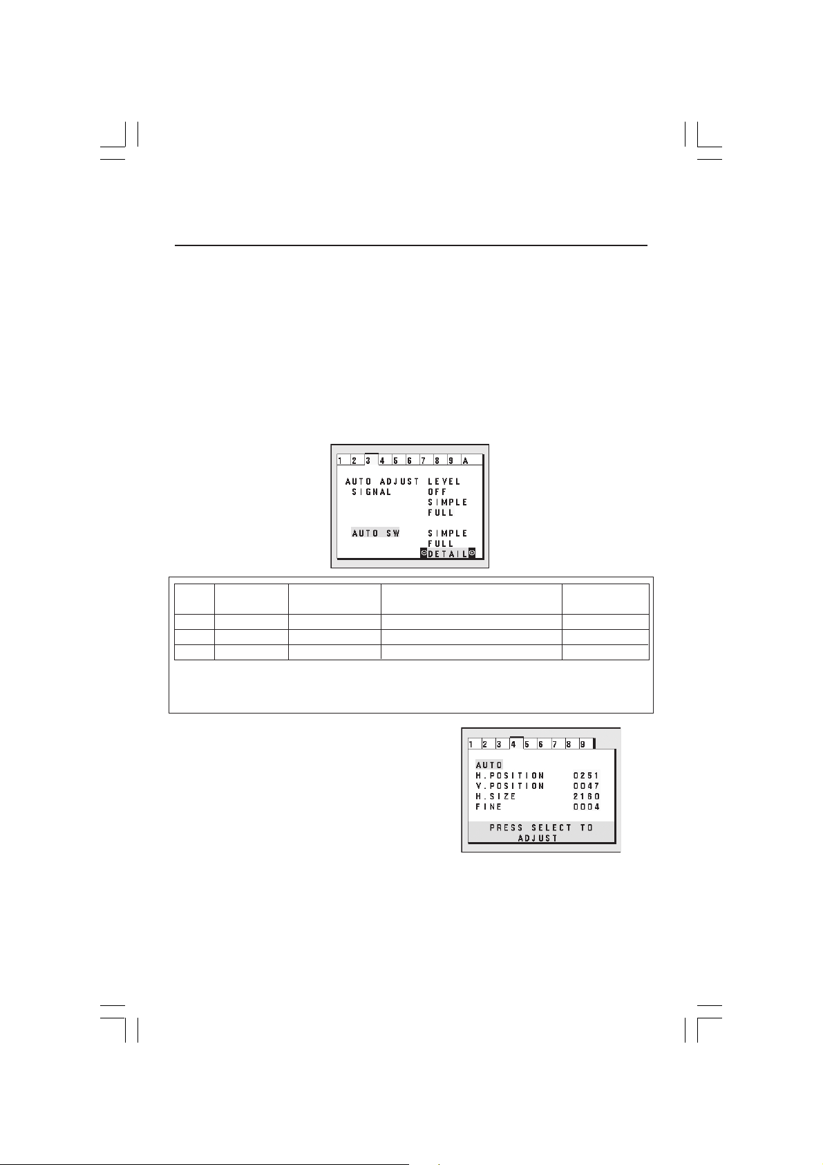
2. In order to perform the adjustment, enter the Advanced OSM:
•Turn off your monitor.
•Turn on your monitor by pressing the “POWER” and “SELECT” buttons simultaneously
to open the Advanced OSM menu.
3.In Tag 3, set the Auto Adjust Level (Auto SW) to “DETAIL”.
"Size" "Fine"
"Position"
SIMPLE X
FULL X
DETAIL
O: Automatic adjustment is performed.
X: Automatic adjustment is not performed.
*1: Black level, RGB sharpness, RGB delay and RGB position are adjusted using Long Cable Software.
O
O
O
"
Contrast"
X
O
OO
Black Level,
Long cable capability *1
Time
1.5 seconds
2 seconds
10 to 20 seconds
4.In Tag 4, select “AUTO” and press “SELECT” to
perform full adjustment.
5. NEC-Mitsubishi recommends changing (Tag 3)
“AUTO SW”/ “DETAIL” to “SIMPLE” after auto
adjust.
6.Exit the Advanced OSM by turning off and
restarting your monitor.
For additional information on user controls and software utilities, visit our website at
www.necmitsubishi.com
11
LCD2180UXManual1020.p65 10/21/03, 9:10 AM11
Page 14

Recommended Use
Safety Precautions and Maintenance
FOR OPTIMUM PERFORMANCE, PLEASE NOTE THE
FOLLOWING WHEN SETTING UP AND USING
THE MULTISYNC
• DO NOT OPEN THE MONITOR. There are no user serviceable parts inside and opening or
removing covers may expose you to dangerous shock hazards or other risks. Refer all servicing to
qualified service personnel.
• Do not spill any liquids into the cabinet or use your monitor near water.
• Do not insert objects of any kind into the cabinet slots, as they may touch dangerous voltage
points, which can be harmful or fatal or may cause electric shock, fire or equipment failure.
• Do not place any heavy objects on the power cord. Damage to the cord may cause shock or fire.
• Do not place this product on a sloping or unstable cart, stand or table, as the monitor may fall,
causing serious damage to the monitor.
• When operating the MultiSync LCD monitor with its AC 125-240V power supply, use a power
supply cord that matches the power supply voltage of the AC power outlet being used. The power
supply cord you use must have been approved by and comply with the safety standards of your
country. (Type H05VV-F should be used in Europe)
• In UK, use a BS-approved power cord with molded plug having a black (5A) fuse installed for use
with this monitor. If a power cord is not supplied with this monitor, please contact your supplier.
• Do not place any objects onto the monitor and do not use the monitor outdoors.
• The inside of the fluorescent tube located within the LCD monitor contains mercury.
Please follow the bylaws or rules of your municipality to dispose of the tube properly.
Immediately unplug your monitor from the wall outlet and refer servicing to qualified service
personnel under the following conditions:
• When the power supply cord or plug is damaged.
• If liquid has been spilled, or objects have fallen into the monitor.
• If the monitor has been exposed to rain or water.
• If the monitor has been dropped or the cabinet damaged.
• If the monitor does not operate normally by following operating instructions.
• Do not bend power cord.
• Do not use monitor in high temperatured, humid, dusty, or oily areas.
• If glass is broken, handle with care.
• Do not cover vent on monitor.
• If monitor or glass is broken, do not come in contact with the liquid crystal and handle with care.
• Allow adequate ventilation around the monitor so that heat can properly dissipate. Do
not block ventilated openings or place the monitor near a radiator or other heat
sources. Do not put anything on top of monitor.
• The power cable connector is the primary means of detaching the system from the
CAUTION
Image Persistence
Image persistence is when a residual or “ghost” image of a previous image remains visible on the
screen. Unlike CRT monitors, LCD monitors’ image persistence is not permanent, but constant images
being displayed for a long period of time should be avoided.
To alleviate image persistence, turn off the monitor for as long as the previous image was displayed.
For example, if an image was on the monitor for one hour and a residual image remains, the monitor
should be turned off for one hour to erase the image.
NOTE: As with all personal display devices, NEC-Mitsubishi Electronics Display recommends using a
moving screen saver at regular intervals whenever the screen is idle or turning off the monitor when
not in use.
power supply. The monitor should be installed close to a power outlet which is easily accessible.
• Handle with care when transporting. Save packaging for transporting.
®
LCD COLOR MONITOR:
12
LCD2180UXManual1020.p65 10/21/03, 9:10 AM12
Page 15
Recommended Use –continued
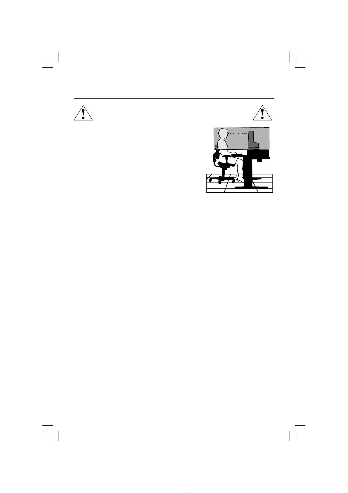
CORRECT PLACEMENT AND ADJUSTMENT OF THE MONITOR
CAN REDUCE EYE, SHOULDER AND NECK FATIGUE. CHECK THE
FOLLOWING WHEN YOU POSITION THE MONITOR:
• For optimum performance, allow 20 minutes for
warm-up.
• Adjust the monitor height so that the top of the
screen is at or slightly below eye level. Your eyes
should look slightly downward when viewing the
middle of the screen.
•
Position your monitor no closer than 16 inches
and no further away than 28 inches from your
eyes. The optimal distance is 20 inches.
• Rest your eyes periodically by focusing on an
object at least 20 feet away. Blink often.
• Position the monitor at a 90° angle to windows and other light sources to
minimize glare and reflections. Adjust the monitor tilt so that ceiling lights do
not reflect on your screen.
• If reflected light makes it hard for you to see your screen, use an antiglare filter.
•
Clean the LCD monitor surface with a lint-free, non-abrasive cloth. Case of
persistent dirt, wipe with cloth permeated by water, ethanol, isopropylalcohol completely. Avoid using any cleaning solution or glass cleaner (ex
Acid, Alkali and Acetone)
• Adjust the monitor’s brightness and contrast controls to enhance readability.
• Use a document holder placed close to the screen.
• Position whatever you are looking at most of the time (the screen or
reference material) directly in front of you to minimize turning your head
while you are typing.
• Avoid displaying fixed patterns on the monitor for long periods of time to avoid
image persistence (after-image effects).
• Get regular eye checkups.
Ergonomics
To realize the maximum ergonomics benefits, we recommend the following:
•
Adjust the Brightness until the background raster disappears
•
Do not position the Contrast control to its maximum setting
•
Use the preset Size and Position controls with standard signals
•
Use the preset Color Setting
•
Use non-interlaced signals with a vertical refresh rate moer than 60Hz
•
Do not use primary color blue on a dark background, as it is difficult to see and
may produce eye fatigue to insufficient contrast
For more detailed information on setting up a healthy work environment, write the
American National Standard for Human Factors Engineering of Visual Display Terminal
Workstations – ANSI-HFS Standard No. 100-1988 – The Human Factors Society, Inc.
P.O. Box 1369, Santa Monica, California 90406.
.
13
LCD2180UXManual1020.p65 10/21/03, 9:10 AM13
Page 16
Specifications
Monitor MultiSync® LCD2180UX Notes
Specifications Monitor
LCD Module Diagonal: 21.3 inch Active matrix; thin film transistor (TFT)
Input Signal Video: ANALOG 0.7 Vp-p/75 Ohms Digital Input: DVI
Display Colors 16,777,216 Depends on display card used.
Synchronization Horizontal: 31.5 kHz to 91.1 kHz Automatically
Range Vertical: 50.0 Hz to 85.0 Hz Automatically
Viewing Angle Left/Right: +88˚ (CR>10)
Response Time 20ms (Typ.)
Resolutions Supported Landscape: 720 x 400*1 :VGA text
Active Display Area Landscape : Horiz. : 432 mm/17.0 inches
Power Supply
Current Rating 0.6 – 0.3A
Dimensions Landscape: 467.0 mm (W) x 391 -
Weight 11.0 kg
Environmental Considerations
*1 Interpolated Resolutions: When resolutions are shown that are lower than the pixel count of the LCD module, text may appear different. This
is normal and necessary for all current flat panel technologies when displaying non-native resolutions full screen. In flat panel technologies, each
dot on the screen is actually one pixel, so to expand resolutions to full screen, an interpolation of the resolution must be done.
NOTE: Technical specifications are subject to change without notice.
Viewable Image Size: 21.3 inch liquid crystal display (LCD); 0.270 mm dot
Native Resolution (Pixel Count): 1600x1200
Sync: Separate sync. TTL Level
Horizontal sync. Positive/Negative
Vertical sync. Positive/Negative
Composite sync. Positive/Negative
Sync on Green (Video 0.7Vp-p and Sync Negative 0.3V p-p)
Up/Down: +88˚ (CR>10)
640 x 480*1 at 60 Hz to 85 Hz
800 x 600*1 at 56 Hz to 85 Hz
832 x 624*1 at 75 Hz
1024 x 768*1 at 60 Hz to 85 Hz
1152 x 870*1 at 75Hz
1280 x 1024
1600 x 1200
Portrait: 480 x 640*1 at 60 Hz to 85 Hz Some systems may not support
Portrait : Horiz. : 324 mm/12.8 inches
Portrait: 358.7 mm (W) x 483.3 - 560.2 mm (H) x 200 mm (D)
Height Adjustment: 115 mm / 4.5 inches (Landscape)
Operating Temperature: 5°C to 35°C/41°F to 95°F
Storage Temperature: -10°C to 60°C/14°F to 140°F
Humidity: 30% to 80%
Humidity: 10% to 85%
600 x 800*1 at 56 Hz to 85 Hz all modes listed.
624 x 832*1 at 75 Hz
768 x 1024*1 at 60 Hz to 85 Hz
870 x 1152*1 at 75 Hz NEC-Mitsubishi Electronics Display cites
1024 x 1280*1 at 60 Hz to 85 Hz recommended resolution for optimal
1200 x 1600
Vert. : 324 mm/12.8 inches
Vert. : 432 mm/17.0 inche
100 -
18.4 inches (W) x 15.4 - 19.9 inches (H) x 7.9 inches (D)
14.1 inches (W) x 19.0 - 22.1 inches (H) x 7.9 inches (D)
24.3 lbs
Feet: 0 to 15,900 Feet
Feet: 0 to 44,600 Feet
*1
at 60 Hz to 85 Hz
at 60 Hz ...............................
at 60 Hz ...............................
240 V ~
50/60 Hz
506
mm (H) x 200 mm (D)
pitch; 250cd/m2 white luminence; XtraView+™
technology; 500:1 contrast ratio, typical
Some systems may not support
all modes listed.
NEC-Mitsubishi Electronics Display cites
recommended resolution for optimal
display performance.
display performance.
14
LCD2180UXManual1020.p65 10/21/03, 9:10 AM14
Page 17

Features
Ambix+™ Technology: Dual input technology allowing both analog and digital inputs off
of one connector (DVI-I) as well as additional legacy analog support off of a traditional
15-pin VGA connector. Provides traditional MultiSync® technology compatibility for
analog as well as DVI-based digital compatibility for digital inputs. DVI-based digital
interfaces include DVI-D,DFP and P&D.
DVI-I: The integrated interface ratified by the Digital Display Working Group (DDWG)
that allows both digital and analog connectors off of one port. The “I” stands for integration for both digital and analog, The digital portion is DVI-based.
DVI-D: The digital-only subset of DVI ratified by the Digital Display Working Group
(DDWG) for digital connections between computers and displays. As a digital-only
connector, analog support is not provided off a DVI-D connector. As a DVI-based digital
only connection, only a simple adapter is necessary for compatibility between DVI-D and
other DVI-based digital connectors such as DFP and P&D.
DFP (Digital Flat Panel): An all-digital interface for flat panel monitors which is signal
compatible with DVI. As a DVI-based digital only connection, only a simple adapter is
necessary for compatibility between DFP and other DVI-based digital connectors such as
DVI and P&D.
Built-in tiling feature supports multiple monitor configurations, without the need of multihead graphics cards.
P&D (Plug and Display): The VESA standard for digital flat panel monitor interfaces. It is
more robust than DFP since it allows for other options off a signal connector (options like
USB, analog video and IEEE-1394-995). The VESA committe has recognized that DFP is a
subset of P&D. As a DVI-based connector (for the digital input pins), only a simple
adapter is necessary for compatibility between P&D and other DVI-based digital connector such as DVI and DFP.
Pivoting Stand: Allows users to adjust the monitor to the orientation that best fits their
application, either Landscape orientation for wide documents, or portrait orientation for
the ability to preview a full page on one screen at one time. The Portrait orientation is also
perfect for full screen video conferencing.
Reduced Footprint: Provides the ideal solution for environments requiring superior image
quality but with size and weight limitations. The monitor’s small footprint and low weight
allow it to be moved or transported easily from one location to another.
AccuColor® Control Systems: Allows you to adjust the colors on your screen and customize
the color accuracy of your monitor to a variety of standards.
OSM® (On-Screen Manager) Controls: advanced OSM controls allow you to quickly and
easily adjust all elements of your screen image via simple to use on-screen menus.
ErgoDesign® Features: Enhance human ergonomics to improve the working environment,
protect the health of the user and save money. Examples include
and easy image adjustments, tilt base for preferred angle of vision, small footprint and
compliance with MPRII and TCO guidelines for lower emissions
Plug and Play: The Microsoft® solution with the Windows®95/98/2000/Me/XP operat-
ing system facilitates setup and installation by allowing
(such as screen size and resolutions supported)
optimizing display performance.
directly to your computer, automatically
the monitor to send its capabilities
OSM controls for quick
.
LCD2180UXManual1020.p65 10/21/03, 9:10 AM15
15
Page 18

Features –continued
®
(Intelligent Power Manager) System: Provides innovative power-saving methods that
IPM
allow the monitor to shift to a lower power consumption level when on but not in use,
saving two-thirds of your monitor energy costs, reducing emissions and lowering the air
conditioning costs of the workplace.
Multiple Frequency Technology: Automatically adjusts monitor to the display card’s
scanning frequency, thus displaying the resolution required.
FullScan® Capability: Allows you to use the entire screen area in most resolutions,
significantly expanding image size.
XtraView+™ Wide Viewing Angle Technology: Allows the user to be able to see the
monitor from any angle (176 degrees) from any orientation — Portrait or Landscape.
Provides full 176° viewing angles either up, down, left or right.
VESA® Standard Mounting Interface: Allows users to connect their MultiSync monitor to
any VESA standard third party mounting arm or bracket. Allows for the monitor to be
mounted on a wall or an arm using any third party compliant device.
Ultra-thin-frame design allows you to view more of your ideas and less of the monitor
bezel, while freeing up more horizontal and vertical desktop space for multiple-monitor
applications.
NaViSet™ software offers an expanded and intuitive graphical interface, allowing you to
more easily adjust OSM display settings via mouse and keyboard.
CableComp™ automatic long cable compensation prevents image quality degradation
caused by long cable lengths.
Advanced No Touch Auto Adjust™ provides optimal image settings upon initial power-on
and closed signal changes.
Rapid Response™ delivers virtually uninterrupted, undistorted viewing of full-motion video
applications.
sRGB Color Control: A new optimized color management standard which allows for
color matching on computer displays and other peripherals. The sRGB, which is based on
the calibrated color space, allows for optimal color representation and backward compatibility with other common color standards.
Pivot capability and adjustable stand add flexibility to your viewing preferences.
Anti-glare and Low-reflection Screen: an anti-glare and low-reflection screen reduces
glare and ambient reflection. The BLACK level perception of the monitor is improved
resulting in a clearer image.
GammaComp™: Internal circuitry automatically converts 8-bit data from the PC to 10bit and back to 8-bit, producing smooth, accurate color tones. Gamma can be set by
using preset values or creating a custom setting from 0.5 to 4.0 in increments of 0.1.
LCD2180UXManual1020.p65 10/21/03, 9:10 AM16
16
Page 19

Troubleshooting
No picture
•
The signal cable should be completely connected to the display card/computer.
• The display card should be completely seated in its slot.
• Check the Vacation Switch should be in the ON position.
• Front Power Switch and computer power switch should be in the ON position.
•
Check to make sure that a supported mode has been selected on the display card or system being used.
(Please consult display card or system manual to change graphics mode.)
• Check the monitor and your display card with respect to compatibility and recommended settings.
• Check the signal cable connector for bent or pushed-in pins.
• Check the signal input, “INPUT 1” or “INPUT 2”.
• Ensure the DVI input mode is set to DIGITAL when the MAC digital output is connected to the DVI-I
(Input1) connector.
Power Button does not respond
• Unplug the power cord of the monitor from the AC outlet to turn off and reset the monitor.
• Check the Vacation Switch on the left side of the monitor.
Image Persistence
•
Image persistence is when a residual or “ghost” image of a previous image remains visible on the screen.
Unlike CRT monitors, LCD monitors’ image persistence is not permanent, but constant images being displayed
for a long period of time should be avoided. To
as the previous image was displayed. For example, if an image was on the monitor for one hour and a
residual image remains, the monitor should be turned off for one hour to erase the image.
NOTE: As with all personal display devices, NEC-Mitsubishi Electronics Display recommends using a
moving screen saver at regular intervals whenever the screen is idle or turning off the monitor when not
in use.
Message “OUT OF RANGE” is displayed (screen is either blank or shows rough images only)
• Image is displayed only roughly (pixels are missing) and OSM warning “OUT OF RANGE” is displayed: Either
signal clock or resolution is too high. Choose one of the supported modes.
• OSM warning “OUT OF RANGE” is displayed on a blank screen: Signal frequency is out of range. Choose one
of the supported modes.
Image is unstable, unfocused or swimming is apparent
• Signal cable should be completely attached to the computer.
• Use the OSM Image Adjust controls to focus and adjust display by
increasing or decreasing the fine total. When the display mode is changed, the OSM Image Adjust
settings may need to be readjusted.
• Check the monitor and your display card with respect to compatibility
and recommended signal timings.
•
If your text is garbled, change the video mode to non-interlace and use 60Hz refresh rate.
LED on monitor is not lit
• Power Switch should be in the ON position and power cord should be connected.
Display image is not sized properly
• Use the OSM Image Adjust controls to increase or decrease the Coarse total.
•
Check to make sure that a supported mode has been selected on the display card or system being used.
(Please consult display card or system manual to change graphics mode.)
No Video
• If no video is present on the screen, turn the Power button off and on again.
• Make certain the computer is not in a power-saving mode (touch the keyboard or mouse).
No tilt
• Rotate the screen to 90˚ clockwise until you hear one click.
• Refer to the Quick Start section, “Remove monitor stand for mounting” to insure correct installation of
stand.
(no green or amber color can be seen)
alleviate image persistence, turn off the monitor for as long
LCD2180UXManual1020.p65 10/21/03, 9:10 AM17
17
Page 20

References
NEC-Mitsubishi Monitor Customer Service & Support
Customer Service and Technical Support:
Parts and Accessories/Macintosh
Cable Adapter: (888) NEC-MITS [888-632-6487]
Customer Service Policies & Processes: http://www.necmitsubishi.com/
Online Technical Support
Knowledge Base: http://www.necmitsubishi.com/
Customer Service & Technical
Support Email: http://www.necmitsubishi.com/
Sales and Product Information
Sales Information Line: (888) NEC-MITS [888-632-6487]
Canadian Customers: (866) 771-0266, Ext#: 4037
Government Sales: (800) 284-6320
Government Sales email: gov@necmitsubishi.com
(800)632-4662
Fax: (800) 695-3044
css/ServicePolicies/ServicePolicies.htm
css/knowledgebase.cfm
css/techform.htm
Electronic Channels
World Wide Web: http://www.necmitsubishi.com
Product Registration: http://www.necmitsubishi.com/
productregistration
European Operations: http://www.nec-mitsubishi.com
Windows® 95/98/Me/2000/XP INF File:
Long Cable Software:
LCD2180UXManual1020.p65 10/21/03, 9:10 AM18
http://
www.necmitsubishi.com and select
“Downloads and Drivers”
http://
www.necmitsubishi.com
18
Page 21

Limited Warranty
NEC-Mitsubishi Electronics Display of America, Inc. (hereinafter “NMD-A”) warrants this
Product to be free from defects in material and workmanship and, subject to the conditions set
forth below, agrees to repair or replace (at NMD-A’s sole option) any part of the enclosed unit
which proves defective for a period of three (3) years from the date of first consumer purchase.
Spare parts are warranted for ninety (90) days. Replacement parts or unit may be new or
refurbished and will meet specifications of the original parts or unit.
This warranty gives you specific legal rights and you may also have other rights, which vary
from state to state. This warranty is limited to the original purchaser of the Product and is not
transferable. This warranty covers only NMD-A-supplied components. Service required as a
result of third party components is not covered under this warranty. In order to be covered
under this warranty, the Product must have been purchased in the U.S.A. or Canada by the
original purchaser. This warranty only covers Product distribution in the U.S.A. or Canada by
NMD-A No warranty service is provided outside of the U.S.A. or Canada. Proof of Purchase
will be required by NMD-A to substantiate date of purchase. Such proof of purchase must be
an original bill of sale or receipt containing name and address of seller, purchaser, and the
serial number of the product.
It shall be your obligation and expense to have the Product shipped, freight prepaid, or
delivered to the authorized reseller from whom it was purchased or other facility authorized
by NMD-A to render the services provided hereunder in either the original package or a
similar package affording an equal degree of protection. All Products returned to NMD-A for
service MUST have prior approval, which may be obtained by calling 1-800-632-4662. The
Product shall not have been previously altered, repaired, or serviced by anyone other than a
service facility authorized by NMD-A to render such service, the serial number of the product
shall not have been altered or removed. In order to be covered by this warranty the Product
shall not have been subjected to displaying of fixed images for long periods of time resulting
in image persistence (afterimage effects), accident, misuse or abuse or operated contrary to
the instructions contained in the User’s Manual. Any such conditions will void this warranty.
NMD-A SHALL NOT BE LIABLE FOR DIRECT, INDIRECT, INCIDENTAL, CONSEQUENTIAL,
OR OTHER TYPES OF DAMAGES RESULTING FROM THE USE OF ANY NMD-A PRODUCT
OTHER THAN THE LIABILITY STATED ABOVE. THESE WARRANTIES ARE IN LIEU OF ALL
OTHER WARRANTIES EXPRESS OR IMPLIED, INCLUDING, BUT NOT LIMITED TO, THE
IMPLIED WARRANTIES OF MERCHANTABILITY OR FITNESS FOR A PARTICULAR PURPOSE.
SOME STATES DO NOT ALLOW THE EXCLUSION OF IMPLIED WARRANTIES OR THE
LIMITATION OR EXCLUSION OF LIABILITY FOR INCIDENTAL OR CONSEQUENTIAL DAMAGES SO THE ABOVE EXCLUSIONS OR LIMITATIONS MAY NOT APPLY TO YOU.
This Product is warranted in accordance with the terms of this limited warranty. Consumers
are cautioned that Product performance is affected by system configuration, software, the
application, customer data, and operator control of the system, among other factors. While
NMD-A Products are considered to be compatible with many systems, specific functional
implementation by the customers of the Product may vary. Therefore, suitability of a Product
for a specific purpose or application must be determined by consumer and is not warranted
by NMD-A.
For the name of your nearest authorized NEC-Mitsubishi Electronics Display service facility,
contact NEC-Mitsubishi Electronics Display of America at 1-800-632-4662.
LCD2180UXManual1020.p65 10/21/03, 9:10 AM19
19
Page 22

TCO’99 –Black Model
Congratulations! You have just purchased a TCO’99 approved and
labelled product!Your choice has provided you with a product developed
for professional use. Your purchase has also contributed to reducing the
burden on the environment and also to the further development of
environmentally adapted electronics products.
Why do we have environmentally labelled computers?
In many countries, environmental labelling has become an established method for encouraging the adaptation of goods and services to the environment. The main problem, as far as
computers and other electronics equipment are concerned, is that environmentally harmful
substances are used both in the products and during the manufacturing. Since it has not been
possible for the majority of electronics equipment to be recycled in a satisfactory way, most
of these potentially damaging substances sooner or later enter Nature.
There are also other characteristics of a computer, such as energy consumption levels, that are
important from the viewpoints of both the work (Internal) and natural (external) environments.
Since all methods of conventional electricity generation have a negative effect on the
environment (acidic and climate-influencing emissions, radioactive waste, etc.), it is vital to
conserve energy. Electronics equipment in offices consume an enormous amount of energy
since they are often left running continuously.
What does labelling involve?
This product meets the requirements for the TCO’99 scheme which provides for international and
environmental labelling of personal computers. The labelling scheme was developed as a joint
effort by the TCO (The Swedish Confederation of Professional Employees), Svenska
Naturskyddsforeningen (The Swedish Society for Nature Conservation) and Statens Energimyndighet
(The Swedish National Energy Administration).
The requirements cover a wide range of issues: environment, ergonomics, usability, emission of
electrical and magnetic fields, energy consumption and electrical and fire safety.
The environmental demands concern restrictions on the presence and use of heavy metals,
brominated and chlorinated flame retardants, CFCs (freons) and chlorinated solvents, among other
things. The product must be prepared for recycling and the manufacturer is obliged to have an
environmental plan which must be adhered to in each country where the company implements its
operational policy. The energy requirements include a demand that the computer and/or display,
after a certain period of inactivity, shall reduce its power consumption to a lower level in one or
more stages. The length of time to reactivate the computer shall be reasonable for the user.
Labelled products must meet strict environmental demands, for example, in respect of the reduction
of electric and magnetic fields, physical and visual ergonomics and good usability.
Environmental Requirements
Flame retardants
Flame retardants are present in printed circuit boards, cables, wires, casings and housings. In turn,
they delay the spread of fire. Up to thirty percent of the plastic in a computer casing can consist of
flame retardant substances. Most flame retardants contain bromine or chloride and these are
related to another group of environmental toxins, PCBs, which are suspected to give rise to severe
health effects, including reproductive damage in fisheating birds and mammals, due to the bio-
20
LCD2180UXManual1020.p65 10/21/03, 9:10 AM20
Page 23

TCO’99 –continued
accumulative* processes. Flame retardants have been found in human blood and researchers fear
that disturbances in foetus development may occur.
TCO’99 demand requires that plastic components weighing more than 25 grams must not contain
flame retardants with organically bound chlorine and bromine. Flame retardants are allowed in
the printed circuit boards since no substitutes are available.
Lead**
Lead can be found in picture tubes, display screens, solders and capacitors. Lead damages the
nervous system and in higher doses, causes lead poisoning.
TCO’99 requirement permits the inclusion of lead since no replacement has yet been developed.
Cadmium**
Cadmium is present in rechargeable batteries and in the colourgenerating layers of certain
computer displays. Cadmium damages the nervous system and is toxic in high doses.
TCO’99 requirement states that batteries, the colourgenerating layers of display screens and the
electrical or electronics components must not contain any cadmium.
Mercury**
Mercury is sometimes found in batteries, relays and switches, Mercury damages the nervous system
and is toxic in high doses.
TCO’99 requirement states that batteries may not contain any Mercury. It also demands that no
mercury is present in any of the electrical or electronics components associated with the display unit.
CFCs (freons)
CFCs (freons) are sometimes used for washing printed circuit boards. CFCs break down ozone and
thereby damage the ozone layer in the stratosphere, causing increased reception on Earth of
ultraviolet light with consequent increased risks of skin cancer (malignant melanoma).
The relevant TCO’99 requirement; Neither CFCs nor HCFCs may be used during the manufacturing
and assembly of the product or its packaging.
*Bio-accumulative is defined as substances which accumulate within living organisms.
**Lead, Cadmium and Mercury are heavy metals which are Bio-accumulative.
To obtain complete information on the environmental criteria document, order from:
TCO Development Unit
SE-114 94 Stockholm
SWEDEN
FAX Number: +46 8 782 92 07
E-mail (Internet): development@tco.se
You may also obtain current information on TCO’99 approved and labelled products by
visiting their website at: http://www.
LCD2180UXManual1020.p65 10/21/03, 9:10 AM21
tcodevelopment
21
.com/
Page 24

TCO’03 –White Model
Congratulations!
The display you have just purchased carries the TCO’03
Displays label. This means that your display is designed,
manufactured and tested according to some of the strictest
quality and environmental requirements in the world. This makes
for a high performance product, designed with the user in focus
that also minimizes the impact on our natural environment.
Some of the features of the TCO’03 Display requirements:
Ergonomics
• Good visual ergonomics and image quality in order to improve the working
environment for the user and to reduce sight and strain problems. Important
parameters are luminance, contrast, resolution, reflectance, colour rendition
and image stability.
Energy
• Energy-saving mode after a certain time – beneficial both for the user and the
environment
• Electrical safety
Emissions
• Electromagnetic fields
• Noise emissions
Ecology
• The product must be prepared for recycling and the manufacturer must have a
certified environmental management system such as EMAS or ISO 14 001
• Restrictions on:
- chlorinated and brominated flame retardants and polymers
- heavy metals such as cadmium, mercury and lead.
The requirements included in this label have been developed by TCO Development in cooperation with scientists, experts, users as well as manufacturers all over the world.
Since the end of the 1980s TCO has been involved in influencing the development of IT
equipment in a more user-friendly direction. Our labelling system started with displays in
1992 and is now requested by users and IT-manufacturers all over the world.
For more information, please visit
www.tcodevelopment.com
22
LCD2180UXManual1020.p65 10/21/03, 9:10 AM22
Page 25

Manufacturer’s Recycling and Energy
Information
NEC-Mitsubishi Electric Visual Systems Corp. is strongly committed to environmental
protection and sees recycling as one of the company’s top priorities in trying to minimize
the burden placed on the environment. We are engaged in developing environmentallyfriendly products, and always strive to help define and comply with the latest
independent standards from agencies such as ISO (International Organisation for
Standardization) and TCO (Swedish Trades Union).
For more information, and for help in recycling your old NEC or Mitsubishi monitors,
please visit our website at:
http://www.nec-mitsubishi.com (in Europe) or
http://www.nmv.co.jp/environment (in Japan) or
http://www.necmitsubishi.com/markets-solutions/totaltrade (in USA).
Country-specific recycling programmes can also be found at:
Sweden - http://www.el-retur.se
Germany - http://www.recyclingpartner.de/
Holland - http://www.mirec.nl/
Japan - http://www.diarcs.com/
Energy saving
This monitor features an advanced energy saving capability. When a VESA Display
Power Management Signaling (DPMS) Standard signal is sent to the monitor, the Energy
Saving mode is activated. The monitor enters a single Energy Saving mode.
Mode Power consumption LED color
Normal Operation Approx. 52W Green
Energy Saving Mode Less than 1W Amber
Off Mode Less than 0.1W Unlit
23
LCD2180UXManual1020.p65 10/21/03, 9:10 AM23
Page 26

Declaration of the Manufacturer
We hereby certify that the color monitor
MultiSync® LCD2180UX (L213E9)
is in compliance with
Council Directive 73/23/EEC:
– EN 60950
Council Directive 89/336/EEC:
– EN 55022
– EN 61000-3-2
– EN 61000-3-3
– EN 55024
and marked with
NEC-Mitsubishi Electric Visual
Systems Corporation
4-13-23, Shibaura,
Minato-Ku
Tokyo 108-0023, Japan
LCD2180UXManual1020.p65 10/21/03, 9:10 AM24
24
Page 27

AVERTISSEMENT
AFIN D’ÉVITER TOUT RISQUE D’INCENDIE OU D’ÉLECTROCUTION, NE PAS EXPOSER CET APPAREIL À LA PLUIE OU À
L’HUMIDITÉ. NE PAS UTILISER LA FICHE D’ALIMENTATION POLARISÉE AVEC UNE PRISE DE CORDON DE RALLONGE
OU AUTRE PRISE SAUF SI LES BROCHES PEUVENT ÊTRE ENTIÈREMENT INTRODUITES.
NE PAS OUVRIR LE BOÎTIER, LEQUEL CONTIENT DES COMPOSANTS À HAUTE TENSION. CONFIER TOUS TRAVAUX
À DU PERSONNEL TECHNIQUE QUALIFIÉ.
ATTENTION
RISQUE DE DÉCHARGE ÉLECTRIQUE • NE PAS OUVRIR
ATTENTION : POUR ÉVITER TOUT RISQUE D'ÉLECTROCUTION, NE PAS OUVRIR LE COUVERCLE (L'ARRIÈRE). À L'INTÉRIEUR, AUCUNE
PIÈCE NE NÉCESSITE L'INTERVENTION DE L'UTILISATEUR. EN CAS DE PROBLÈME, S'ADRESSER À DU PERSONNEL TECHNIQUE QUALIFIÉ.
Ce symbole est une mise en garde contre les risques d'électrocution que présentent certaines parties dépourvues
d'isolation à l'intérieur de l'appareil. Il est donc dangereux d'établir le moindre contact avec ces parties
Ce symbole prévient l'utilisateur que des directives d'utilisation et de maintenance de cet appareil sont fournies avec
ce guide d’utilisateur. Par conséquent, celles-ci doivent être lues attentivement pour éviter tout incident.
.
Déclaration de conformité – Département des Communications du Canada
DOC : Cet appareil numérique de classe B respecte toutes les exigences du Règlement
sur le matériel à l'origine d'interférences du Canada.
C-UL : Ce produit porte la marque «C-UL» et est conforme aux règlements de sécurité
canadiens selon CAN/CSA C22.2 No. 60950.
Informations FCC
1.
Utiliser les câbles spécifiés fournis avec les moniteur couleur
de ne pas provoquer d'interférences avec la réception radio et télévision
(1) Prière d'utiliser le câble d'alimentation fourni ou équivalent pour assurer la conformité FCC.
(2) Veuillez utiliser le câble de signal vidéo blindé fourni, un mini D-SUB à 15 broches vers le câble
un DVI-A câble ou DVI-D à DVI-D câble.
L'utilisation d'autres câbles et adaptateurs peut provoquer des interférences avec la réception
radio et télévision.
2.
Cet appareil a été testé et s’avère conforme avec les spécifications d'équipements de Classe B, section
15 de la réglementation FCC. Ces spécifications ont été établies pour garantir une protection raisonnable
contre les interférences nuisibles dans une installation résidentielle. Cet appareil génère, utilise et peut
émettre des fréquences radio et, s'il n'est pas installé et utilisé selon les directives de ce guide, il peut
perturber les communications radio. Cependant, il n'est pas garanti qu'aucune interférence ne se produira
dans une installation donnée.
Si cet appareil provoque des interférences nuisibles à la réception radio ou télévision, ce que vous
pouvez déterminer en allumant et en éteignant l'appareil, essayez de remédier au problème en prenant
une ou plusieurs des mesures suivantes :
• Réorienter ou repositionner l'antenne de réception.
• Augmenter la distance entre l'appareil et le récepteur.
• Connecter l'appareil à une prise de courant sur un circuit différent de celui sur lequel le récepteur
est connecté.
• Consulter son revendeur ou un technicien radio/TV pour obtenir de l'aide.
Si nécessaire, l'utilisateur doit contacter le revendeur ou un technicien radio/TV afin d'obtenir des informations supplémentaires. L'utilisateur peut se procurer le livret utile suivant, préparé par la Federal Communications Commission : «How to Identify and Resolve Radio-TV Interference Problems» (Comment cerner et
résoudre les problèmes d’interférences radio/TV). Ce livret est disponible auprès du U.S. Government
Printing Office, Washington, D.C., 20402, Stock No. 004-000-00345-4.
MultiSync LCD2180UXTM (L213E9)
.
afin
LCD2180UXManual1020.p65 10/21/03, 9:10 AM25
25
Page 28

Contenu
La boîte* de votre nouveau moniteur NEC MultiSync® contient :
• Moniteur MultiSync LCD2180UX™ sur tilt/tourillon se place/réglage
•Cordon d'alimentation
•
Câble pour le signal vidéo (
•
Câble pour le signal vidéo
• Manuel de l’utilisateur
•Gaine de câble
Cordon d'alimentation
Mini D-SUB mâle 15
broches vers DVI-A
Mini D-SUB mâle 15 broches vers DVI-A)
(
Câble DVI-D vers DVI-D)
Gaine de câble
LCD2180UX
TM
MultiSync
®
Câble DVI-D vers DVI-D
Manuel de l’utilisateur
* Ne pas oublier de conserver la boîte et le matériel d'emballage d'origine pour transporter ou expédier le moniteur.
26
LCD2180UXManual1020.p65 10/21/03, 9:10 AM26
Page 29

Mise en marche rapide
Pour raccorder le moniteur MultiSync® LCD au système, suivez les directives ciaprès:
1. Mettez l’ordinateur hors tension.
2. Pour un PC ou un Mac équipé d’une sortie numérique DVI : Branchez le câble DVI-D - DVI-D au
connecteur de la carte graphique de votre ordinateur (Figure A.1). Serrez toutes les vis.
Pour un PC équipé d’une sortie analogique : Branchez le câble de signal mini-connecteur D-SUB
15 broches - DVI au connecteur de la carte graphique de votre systém
Pour un Macintosh : Brachez l’adaptateur de câble pour Macintosh de MultiSync à l’ordinateur.
Branchez le câble signal mini D-SUB à 15 broches à l’adaptateur de câble MultiSync pour
Macintosh (Figure B.1).
NOTA : Certains systèmes Macintosh ne nécessitent pas un adaptateur de câble Macintosh.
NOTA : Pour obtenir un adaptateur de câble Macintosh Multisync appeler NEC-Mitsubishi
Electronics Display of America, Inc. au (800) 632-4662.
3. Branchez le câble de signal 15-pin mini D-SUB to DVI-A au connecteur situé à l’arrière du
moniteur à l’entrée 1 ou câble de signal DIV-D à l’entrée 2 (Figure C.1).
NOTA : Une mauvaise connexion des câble peut nuire au fonctionnement, endommager l’affichage
et nuire à la qualité de l’affichage du model LCD et/ou réduire la durée de vie utile du module.
Rassemblez les câbles et rangez-les dans le support avec la gaine de câble. La gaine de
câble peut être fixée à l’avant ou à l’arrière du support (Figure C.1, C.2). Veuillez vérifier
que les câbles ne gênent pas les mouvements du stand (inclinaison, élévation, abaissement
et rotation de l’écran).
e (Figure A.2).
4. Connecter une extrémité du câble d’alimentation électrique sur l’arrivée CA située à
l’arrière du moniteur et l’autre extrémité sur la prise de courant (Figure C.1).
NOTA :
Si vous utilisez ce moniteur à AC125-240V, s'il vous plaît faites référence à section de l'Usage
Recommandée de ce manuel pour sélection adéquate d'AC pouvoir cordon.
5. L’Interrupteur de Vacances sur le côté gauche de l’écran doit être allumai. Allume l’écran (Figure
D.1) de Silhouette de bouton et l’ordinateur.
NOTA : que there a deux interrupteurs : un sur le côté droit et le façade sur côté de l’écran. Pas permute
rapidement ou.
NOTA : Pour le MAC avec sortie numérique : Avant de mettre le MAC sous tension, le mode
d’entrée DVI doit être réglé sur NUMÉRIQUE dans « SÉLECTION DVI » d’OSM en appuyant sur
le bouton « SÉLECTIONNER » puis sur le bouton « CONTRÔLE » lorsque le câble de signal DVI
est branché au connecteur DVI-I (entrée 1) du moniteur. Sinon, il est possible que le MAC ne
puisse être mis sous tension.
6.
Pour conclure l’installation du moniteur MultiSync LCD. Utilisez les commandes OSM suivantes :
• Contraste automatique (Entrée analogigue seulement)
• Réglage automatique (Entrée analogigue seulement)
Pour une description complète de ces commandes OSM, consultez la section Commandes de ce guide.
NOTA :des informations sur le télé chargement du fichier INF Windows® 95/98/Me/2000/XP pour
le moniteur MultiSync LCD2180UX, consultez la section Références de ce manuel.
NOTA :case de probl è me,consultez la section Dépannage de ce manuel.
Figure A.1
Figure A.2
Figure B.1
à
LCD2180UXManual1020.p65 10/21/03, 9:10 AM27
27
Adaptateur de câble
(non fourni)
Remarque: Certains systémes
Macintosh ne nécessitent pas un
adaptateur de
câble Macintosh.
Page 30

Mise en marche rapide (suite)
n
Fixation de produit NEC en option. N’utilisez pas ce
connecteur sauf indication contraire.
l’interrupteur
de vacances
Bouton
d’alimentatio
Levez et baissez l’écran du moniteur
Le moniteur peut être levé ou baissé en mode Portrait ou Paysage. Pour lever ou baisser
l’écran, placez les mains de chaque côté du moniteur et positionnez-le à la hauteur de
votre choix. (Figure RL.1).
NOTA: Manipule sur soin quand augmentant ou l’écran diminuant écran.
Figure RL.1
LCD2180UXManual1020.p65 10/21/03, 9:10 AM28
28
Page 31

Mise en marche rapide (suite)
Rotation de l’écran
Avant de tourner l’écran, celui-ci doit être levé au niveau maximum afin d’éviter tout choc
contre le bureau ou de pincer vos doigts. Pour lever l’écran, placez les mains de chaque
côté du moniteur et levez-le jusqu’à la hauteur maximum (Figure RL.1).
Pour tourner l’écran, placez les mains de chaque côté du moniteur et tournez-le dans le sens
horaire de Paysage à Portrait ou dans le sens inverse de Portrait à Paysage (Figure R.1).
Pour alterner l’orientation de menu d’OSM entre Landscape et Portrait, référer au section
de “Commandes”, function de “Rotation de l’OSM”.
Figure R.1
Incliner
Mettez vos mains sur les côtés inférieur et
supérieur de l'écran et réglez l'inclinaison
comme désirée
Pivoter
Placez les mains de chaque côté de
l'écran et réglez l'orientation comme
désirée (Figure TS.2).
(Figure TS.1).
NOTA: Manipule sur soin quand l’écran inclinant écran.
29
LCD2180UXManual1020.p65 10/21/03, 9:10 AM29
Page 32

Mise en marche rapide (suite)
Enlever le support du moniteur pour le montage
Pour préparer le moniteur à différents types de montage :
1. Déconnectez tous les câbles.
2.
Placez les mains de chaque côté du moniteur en le soulevant dans sa position la plus haute.
3.
Placez le moniteur la face vers le bas sur une surface non abrasive (placez l’écran
sur une plate-forme de 29 mm de manière à ce que le support soit parallèle à la
surface) (Figure S.1).
29mm
4. Ôtez les deux vis supérieures qui fixent le moniteur au support (Figure S.2).
Pivotez le support à 180° dans le sens inverse des aiguilles d’une montre (vous
devez entendre deux clics). Ôtez les vis de la base (Figure S.3) et dégagez le
support. Le moniteur est maintenant prêt à être monté de façon différente.
5. Renversez ce processus pour rattacher le support: serrez les deux vis inférieures,
tournez le support 180˚, dans le sens inverses des aiguilles d’une montre (vous
entendrez deux “clicks”), et serrez les deux vis supérieures.
NOTA : Utilisez uniquement une méthode de montage compatible VESA (Pas de 100mm).
NOTA : Prenez des précautions pour ôter le support du moniteur.
Attention :
LCD2180UXManual1020.p65 10/21/03, 9:10 AM30
Veuillez utiliser les vis fournies (4) pour le montage. Afin de respecter les consignes de
sécurité, le moniteur doit être monté sur un bras garantissant la stabilité nécessaire en
fonction du poids du moniteur. Le moniteur LCD doit être uniquement utilisé avec un
bras homologué (par exemple, portant la marque GS).
Figure S.2 and Figure S.3
30
Page 33

Commandes
Les boutons de réglage OSM situés sur l’avant du moniteur fournissent les fonctions
suivantes :
Pour accéder au menu OSM, appuyez sur une des touches de commande
( , , –, +)
À transformer signale de l’entrée, presser le SELECT bouton.
NOTA: Menu de OSM doit être fermé pourvoir modifier le signal déntrée et pour.
EXIT Quitte les commandes OSM.
CONTROL /
ADJUST
SELECT Activez la fonction Réglage automatique. Entrez les commandes OSM.
RESET Réinitialise le menu de commandes en surbrillance aux réglages d’usine.
NOTA : En appuyant sur le bouton RESET dans un menu ou dans un sous-menu, une fenêtre s’affiche vous
permettant d’annuler la fonction RESET en appuyant sur le bouton EXIT.
Commandes de luminosité et de contraste
Réglage Auto (Entrée analogique seulement)
Commandes de l’image
.
Menu principal
Revient au menu principal OSM.
Déplace la zone en surbrillance vers la gauche ou la droite pour choisir un menu de commande.
Déplace la zone en surbrillance vers le haut ou vers le bas pour choisir l’une des commandes.
–/+
Déplacez la barre de gauche à droite pour augmenter ou diminuer le réglage.
Entrez le sous-menu OSM.
LUMINOSITÉ
Règle la luminosité globale de l’image et du fond de l’écran.
CONTRASTE
Règle la luminosité de l’image en fonction du fond.
CONTRASTE AUTO. (Entrée analogique seulement)
Règle l’image affichée pour des entrées vidéo non standard.
LUMINOSITÉ AUTO.
Cette fonction permet de régler automatiquement la luminosité afin d'obtenir les
meilleurs contrastes en fonction d'une zone d'affichage en blanc.
Règle automatiquement la position de l’image, la dimension horizontale et la finesse.
GAUCHE/DROITE
Contrôle la position horizontale de l’image dans la zone d’affichage du LCD.
BAS/HAUT
Contrôle la position verticale de l’image dans la zone d’affichage du LCD.
HAUTEUR (Entrée analogique seulement)
Règle la largeur en augmentant ou diminuant ce paramètre.
Si la fonction « Réglage auto » ne vous donne pas un réglage satisfaisant de l’image, il
est possible d’effectuer un réglage supplémentaire avec la fonction « Largeur » (par
points). Pour cela, un motif de test moiré peut être utilisé. Cette fonction peut modifier la
largeur de l’image. Utilisez le menu gauche/droite pour centrer l’image sur l’écran. Si
LCD2180UXManual1020.p65 10/21/03, 9:10 AM31
31
Page 34

Commandes (suite)
la largeur est mal calibrée, le résultat sera semblable à celui du dessin ci-contre.
L'image doit être homogène.
Incorrect
FINESSE
(Entrée analogique seulement)
Améliore le point, la clarté et la stabilité de l’image en augmentant ou diminuant ce
paramètre.
Si les fonctions « Réglage auto » et « Largeur » ne vous donnent pas un réglage
satisfaisant de l’image, vous pouvez la régler avec précision à l'aide de la fonction
« Finesse ». Vous pouvez améliorer la netteté, la clarté et la stabilité de l’image en
augmentant ou diminuant ce paramétre. Pour cela, un motif de test moiré peut être utilisé.
Si la valeur fine est mal calibrée, le résultat sera semblable à celui du dessin ci-contre.
L’image devrait être homogéne.
Incorrect
AccuColor® Control Systems (Système de contrôle des couleurs)
Six préréglages des couleurs vous permettent de régler les couleurs à votre guise (les
préréglages sRGB, NATIVE et PROGRAMMABLE sont des standards et ne peuvent pas être
modifiés). La température des couleurs augmente ou diminue dans chaque préréglage.
R,J,V,C,B,M,S : Augmente ou diminue le Rouge, le Jaune, le Vert, le Cyan, le Bleu, le
Magenta et la Saturation selon ce qui est sélectionné. Le changement de couleur apparaît
à l’écran et le sens (augmentation ou diminution) est indiqué par les barres de couleur.
NATIVE : Réglage d’origine présenté par le panneau LCD et que l’on ne peut modifier.
PROGRAMMABLE : La température et le ton des couleurs qui ont été réglés à l’aide de
l’application logicielle téléchargée appliqués.
Outils 1
NETTETÉ :
toutes les résolutions. Elle est réglable de façon continue afin d'obtenir, comme vous
préférez, une image distincte ou plus floue. Elle est réglée de manière indépendante par
différentes résolutions.
Le nombre d'étapes de réglage dépend du mode d'agrandissement: ARÉT, PLEIN ou ASPECT.
1600 x 1200 correspond au mode ARRÉT.
MODE ÉTENDU : Règle le zoom.
Cette fonction permet de conserver la netteté de l'image numériquement pour
PLEIN : La taille de l’image est agrandie à 1600 x 1200, quelle que soit la résolution.
ASPECT : L’image est agrandie sans modifier le rapport du format.
ARRÉT : L’image n’est pas agrandie.
PERSONNALISÉ (Uniquement en entrée numérique et en résolution 1600 x 1200) :
Sélectionnez l'un des neuf taux d'agrandissement.
Dans ce mode, la résolution peut être faible et l'écran peut présenter des zones
vides. Ce mode est destiné à l’utilisation avec des cartes graphiques spéciales.
Correct
Correct
LCD2180UXManual1020.p65 10/21/03, 9:11 AM32
32
Page 35

Commandes (suite)
DÉTECTION VIDÉO :
plusieurs ordinateurs sont connectés.
1ER DÉTECTÉ : L’entrée vidéo doit être commutée en mode « 1ER DÉTÉCTION ».
S’il n’existe pas de signal d’entrée vidéo, le moniteur recherche un signal vidéo sur
l’autre port d’entrée vidéo. Si le signal vidéo est localisé sur l'autre port, le moniteur
bascule automatiquement le port d’entrée vidéo vers la nouvelle source vidéo
détectée. Le moniteur ne recherchera pas d’autre signal vidéo tant que la source
vidéo actuelle sera présente.
DERNIERE
DÉTÉCTION ». Si le moniteur affiche un signal de la source actuelle et qu’une nouvelle
source vidéo lui est fournie, le moniteur bascule automatiquement vers cette nouvelle
source vidéo. Si aucun signal d'entrée vidéo n'est détecté, le moniteur en recherche un
sur l'autre port d'entrée vidéo. Si le signal vidéo est localisé sur l'autre port, le moniteur
bascule automatiquement le port d’entrée vidéo vers la nouvelle source vidéo détectée.
PAS DE PRIORITÉ :
d’entrée vidéo.
SÉLECTION DVI : Cette fonction sélectionne le mode d’entrée DVI (Entrée 1). En cas de
nouvelle sélection du mode DVI, l’ordinateur devra être redémarré.
AUTO : Avec le câble DVI-D au DVI-D, la SÉLECTION DVI est NUMÉRIQUE. Avec
le câble D-SUB à DVI-A, la SÉLECTION DVI est ANALOGIQUE.
NUMÉRIQUE : L’entrée DVI numérique est disponible.
ANALOGIQUE : L’entrée DVI analogique est disponible.
NOTA: Pour le MAC avec sortie numérique : Avant de mettre le MAC sous tension,
le mode d’entrée DVI doit être réglé sur NUMÉRIQUE dans « SÉLECTION DVI »
d’OSM en appuyant sur le bouton « SÉLECTIONNER » puis sur le bouton
« CONTRÔLE » lorsque le câble de signal DVI est branché au connecteur DVI-I
(entrée 1) du moniteur. Sinon, il est possible que le MAC ne puisse être mis sous
tension.
NOTA: Selon le carte de PC/Video ou le câble utilisé, cette fonction peut pas fonctionner.
ARRÊT PROGRAMMATEUR :
l'utilisateur final sélectionne un laps de temps préréglé.
Outils 2
LANGUE : Les menus des commandes OSM sont disponibles en sept langues.
OSM GAUCHE/DROITE : Vous pouvez choisir l’emplacement sur l’écran de la fenêtre
de commandes OSM. En choisissant Position de l’OSM, vous pouvez régler
manuellement la position du menu de commandes OSM : gauche ou droite.
OSM BAS/HAUT : Vous pouvez choisir l’emplacement sur l’écran de la fenêtre de
commandes OSM. En choisissant Position de l’OSM, vous pouvez régler
manuellement la position du menu de commandes OSM : en bas ou en haut.
EXTINCTION DE L’OSM : Le menu des commandes OSM reste à l’écran aussi
longtemps qu’il est utilisé. Dans le sous-menu Extinction OSM, vous pouvez choisir la
durée d’attente du moniteur entre la dernière pression de touche et l’extinction du menu
des commandes OSM. Les choix prédéfinis sont situés entre 10 et 120 secondes, par
pas de 5 secondes.
VERROUILLAGE OSM : Cette commande bloque totalement l’accès à toutes les
fonctions de commande OSM. Toute tentative d’activation des commandes OSM,
lorsque ce dernier est en mode verrouillé, provoque l’apparition d’un écran informant
que les commandes OSM sont verrouillées. Il existe deux types de VERROUILLAGE
OSM :
Sélectionne la méthode de détection de la vidéo lorsque
DÉTECTÉ
: L’entrée vidéo doit être commutée en mode « DERNIERE
Tant qu’il n’est pas allumé, le moniteur ne vérifie pas l’autre port
Le moniteur sera mis automatiquement hors tension lorsque
LCD2180UXManual1020.p65 10/21/03, 9:11 AM33
33
Page 36

Commandes (suite)
VERROUILLAGE OSM avec les commandes LUMINOSITÉ et CONTRASTE : Pour
activer la fonction de verrouillage OSM, appuyez sur le bouton SÉLECTION, puis sur
la touche « + » et maintenez-les simultanément enfoncés. Pour désactiver le
verrouillage OSM, appuyez sur le bouton SÉLECTION, puis sur la touche « + » et
maintenez-les simultanément enfoncés. Il est possible de régler CONTRASTE et
LUMINOSITÉ en mode verrouillé.
VERROUILLAGE OSM sans commande : Pour activer la fonction de verrouillage
OSM, appuyez sur le bouton SÉLECTION, puis sur la touche « > » et maintenez-les
simultanément enfoncés. Pour désactiver le verrouillage OSM, appuyez sur le bouton
SÉLECTION, puis sur la touche « > » et maintenez-les simultanément enfoncés.
Aucune commande ne peut être réglée en mode verrouillé.
ROTATION DE L’OSM : Pour basculer OSM entre les modes Paysage et Portrait.
NOTIFICAT. RÉSOLUTION :
choisi, un message apparaît à l’écran après 30 secondes, vous avertissant que la résolution n’est
pas à 1600 x 1200.
TOUCHE DE RACCOURCI : Vous pouvez régler directement la luminosité et le
contraste. Lorsque le menu est activé, vous pouvez régler la luminosité avec < ou >.
Lorsque le menu est désactivé, utilisez les touches + ou - pour régler le contraste.
PRÉRÉGLAGE USINE : En choisissant “Factory Preset” vous permet de remettre la plupart
des commandes d’OSM. Les réglages individuels peuvent être réinitialisés en mettant la
commande concernée en surbrillance et en appuyant sur le bouton RESET.
Informations
MODE D’AFFICHAGE : Fournit des informations sur la résolution d’affichage actuelle, des
données techniques comprenant le préréglage de temps utilisé et les fréquences
horizontale et verticale. Augmente ou diminue la résolution actuelle.
INFOS MONITEUR : Indique le nom du modèle et les numéros de série de votre
moniteur.
Avertissements OSM: Les menus Avertissements OSM disparaissent avec le
bouton Exit.
PAS DE SIGNAL : Cette fonction génère un avertissement lorsqu'il n'y a aucun signal
horizontal ou vertical de synchronisation présent. Une fois l'alimentation positionnée
sur MARCHE ou lorsqu'il y a un changement du signal d'entrée, la fenêtre PAS de
Signal apparaît.
NOTIFICAT. RÉSOLUTION : Cette fonction vous avertit de l’utilisation en résolution
optimisée. Après la mise sous tension, ou bien si le signal d’entrée change ou encore
si le signal vidéo ne présente pas de résolution appropriée, la fenêtre notificat.
résolution apparaît. Cette fonction peut être désactivée dans le menu OUTILS.
HORS LIMITE : Cette fonction vous renseigne sur la résolution optimisée et le taux de
rafraîchissement. Après la mise sous tension, ou bien si le signal d’entrée change ou
encore si le signal vidéo ne présente pas de calage approprié, le menu Hors limites
apparaît.
La résolution optimale est de 1600 x 1200. Si MARCHE est
REMARQUE : Si « CHANGER D’ENTREE DVI » s’affiche, commuter sur SELECTION DVI.
Veuillez consulter l’« Annexe » pour en savoir plus sur le menu
utilisateur avancé.
LCD2180UXManual1020.p65 10/21/03, 9:11 AM34
34
Page 37

Mise en marche rapide (suite)
Réglage de la compensation de câble long
La compensation des câbles longs ne peut être effectuée qu’avec des câbles rallongés ou
pour compenser un signal vidéo de qualité médiocre. Il est nécessaire de suivre les étapes
suivantes pour effectuer le réglage de compensation de câble long :
1.Pour un réglage optimal, téléchargez « LCD Long Cable Comp Test Pattern » et le fichier
« Read Me » sur www.necmitsubishi.com et affichez le motif de test pendant ce réglage.
2. Afin d’effectuer le réglage, entrez dans le menu avancé OSM :
• Mettez votre moniteur hors tension.
• Mettez votre moniteur sous tension en appuyant simultanément sur les boutons « MARCHE
» et « SELECT » pour ouvrir le menu avancé OSM.
3.Sur Tag 3, réglez le niveau de réglage automatique (Auto SW) sur « DETAIL ».
"Dimension"
"précision"
"position"
SIMPLE X
FULL X
DÉTAIL
O:
Le réglage automatique est effectué.
X:
Le réglage automatique n’est pas fait.
*1:
Le niveau du noir, la précision RVB, le temps de retard RVB et la position RVB sont
O
O
O
Contraste"
X
O
OO
Le niveau du noir,
Capacité du câble long (*1)
1,5 seconde
2 secondes
10 à 20 secondes
réglés à l’aide du logiciel Câble long.
4.Sur Tag 4, sélectionnez « AUTO » et appuyez sur
« SELECT » pour effectuer le réglage complet.
5. NEC-Mitsubishi recommande de changer (Tag 3) «
AUTO SW »/« DETAIL » en « SIMPLE » après le
réglage automatique.
6.Vous pouvez quitter le menu OSM avancé en éteignant
puis en redémarrant votre moniteur.
Pour de plus amples renseignements au sujet des commandes et des sous-programmes
logiciels, visitez notre site Web sur www.necmitsubishi.com
35
LCD2180UXManual1020.p65 10/21/03, 9:11 AM35
Durée"
Page 38

Usage recommandé
Consignes de sécurité et d’entretien
POUR UN FONCTIONNEMENT OPTIMAL, PRIÈRE DE NOTER CE QUI
SUIT POUR LE RÉGLAGE ET L'UTILISATION DU MONITEUR COULEUR
MULTISYNC® LCD :
• NE PAS OUVRIR LE MONITEUR. Aucune pièce intérieure ne nécessite l'intervention de l'utilisateur,
et l'ouverture ou la dépose des couvercles peut entraîner des risques de décharges électriques
dangereuses ou d'autres risques. Confier tous travaux à du personnel technique qualifié.
• Ne pas renverser de liquides dans le boîtier, ni utiliser le moniteur près de l'eau.
•
Ne pas introduire d'objets de quelque nature que ce soit dans les fentes du boîtier car ceux-ci
pourraient toucher des endroits sous tension dangereuse, ce qui peut provoquer des blessures, voire
être fatal, ou peut occasionner une décharge électrique, un incendie ou une panne de l'appareil.
• Ne pas placer d'objets lourds sur le cordon d'alimentation. Un cordon endommagé peut
occasionner une décharge électrique ou un incendie.
• Ne pas placer cet appareil sur un chariot, un support ou une table inclinée ou instable, afin
d'éviter que le moniteur ne tombe, occasionnant de sérieux dommages au moniteur.
• Pour l'utilisation du moniteur MultiSync LCD avec l'alimentation AC mondiale de
125-240 V, utiliser un cordon d'alimentation qui correspond à la tension de l'alimentation fournie
à la prise de courant AC. Le cordon d'alimentation utilisé doit être agréé et en conformité avec les
normes de sécurité de son pays. (Type H05VV-F à utiliser sauf au Europe.)
• Au R, –U., utilisez avec ce moniteur un cordon d’alimrntation approuvé BS avec fiche moulée d’un
fusible noir (5A). Si un cordon d’alimentation n’a pas été fourni avec ce moniteur, veuillez
contacter votre fournisseur.
• Ne placer aucun objet sur le moniteur et ne pas l’utiliser en extérieur.
• L’intérieur du tube fluorescent situé dans le moniteur contient du mercure. Pour l’élimination
appropriée, observez les règlements en vigueur dans votre région.
Débrancher immédiatement le moniteur de la prise murale et confier la réparation à du personnel
technique qualifié dans les cas suivants :
• Lorsque le cordon d'alimentation ou la fiche est endommagé(e).
• Si du liquide a été renversé ou des objets sont tombés à l'intérieur du moniteur.
• Si le moniteur a été exposé à la pluie ou à de l'eau.
• Si le moniteur est tombé ou le boîtier est endommagé.
• Si le moniteur ne fonctionne pas normalement en suivant les directives d'utilisation.
• Ne courbe pas le pouvoir du cordon.
• N’utilise pas votre écran dans de hautes températures humides poussiéreuses près d’huile ou.
• Ne couvre pas l’armoire fente ou usage rayonnai mauvaise chaleur.
• Regal toujours glass sur soin.
•
Si écran ou verre est rodé, ne supporter pas ne venir pas touche le liquide crystal et manche sur soin
AVERTISSEMENT
Persistance de l’image
la persistance de l’image se présente lorsqu’une image résiduelle ou “ fantôme ” d’une image précédente reste
visible sur l’écran. Contrairement aux moniteurs à tube cathodique, la persistance de le l’image des moniteurs LCD
n’est pas permanente, mais l’affichage d’images constantes pendant une longue période de temps doit être évitée.
Pour remédier à la persistance de l’image, mettez le moniteur hors tension pendant une durée égale à celle de
l’affichage de l’image précédente. Par exemple, si une image est restée affichée sur l’écran pendant une heure et
qu’il reste une image résiduelle, le moniteur doit être mis hors tension pendant une heure pour effacer l’image.
NOTA: Comme pour tous les équipements d’affichage personnels, NEC-Mitsubishi Electronics Display recommande
l’utilisation d’un économiseur d’écran mobile à des intervalles réguliers, à chaque fois que l’écran est en veille, ou
d’éteindre le moniteur lorsqu’il n’est pas utilisé.
•
Prévoir une aération suffisante autour du moniteur pour que la chaleur puisse se
dissiper correctement. Ne pas obstruer les ouvertures de ventilation ni placer le
moniteur près d'un radiateur ou autre source de chaleur. Ne rien poser sur le moniteur.
• La fiche du cordon d'alimentation est le moyen principal de débrancher le système
de l'alimentation. Le moniteur doit être installé à proximité d'une prise de courant
facilement accessible.
•
Manipuler avec soin lors du transport. Conserver l'emballage pour le transport.
.
LCD2180UXManual1020.p65 10/21/03, 9:11 AM36
36
Page 39

Usage recommandé (suite)
LA MODIFICATION DE LA POSITION ET DU RÉGLAGE DU MONITEUR
PEUT RÉDUIRE LA FATIGUE DES YEUX, DES ÉPAULES ET DE LA NUQUE.
OBSERVER LES DIRECTIVES CI-APRÈS LORS DU POSITIONNEMENT
DU MONITEUR :
• Pour une performance optimale, laissez le moniteur
se réchauffer pendant 20 minutes.
• Régler la hauteur du moniteur de sorte que le dessus
de l'écran soit au niveau ou légèrement en-dessous
du niveau des yeux. Les yeux doivent regarder
légèrement vers le bas lorsque l'on regarde le milieu
de l'écran.
• Positionner le moniteur à une distance minimale de
40 cm (16 po) et maximale de 70 cm (28 po) des yeux.
La distance optimale est de 50 cm (20 po).
• Reposer ses yeux régulièrement en regardant vers un
objet situé à au moins 6 m (20 pieds). Cligner régulièrement.
• Positionner le moniteur à un angle de 90° par rapport aux fenêtres et autres sources de
lumière, afin de réduire au maximum les reflets et l'éblouissement. Régler l'inclinaison
du moniteur de sorte que l'éclairage du plafond ne soit pas reflété sur l'écran.
• Si une lumière réfléchie rend la vision de l'écran difficile, utiliser un filtre anti-reflet.
• Nettoyez le moniteur LCD avec un chiffon sans peluches et non abrasif. Si ce n’est
pas suffisant, essuyez avec un chiffon imprégné d’eau, d’éthanol ou d’alcool
isopropylique. N’utilisez pas de produit d’entretien ou de nettoyant pour vitres (par
exemple, acide, alcali ou acétone).
• Régler les commandes de luminosité et de contraste du moniteur pour améliorer la
lisibilité.
• Utiliser un support de document placé près de l'écran.
• Positionner ce que l'on regarde le plus souvent (l'écran ou les documents de référence)
directement devant soi pour réduire au maximum les mouvements de la tête lorsque
l'on dactylographie.
• Pour éviter la persistance d’images (images rémanentes), n’affichez pas des motifs fixes
sur le moniteur pendant de longues périodes.
• Consulter régulièrement un ophtalmologiste.
Ergonomie
Pour optimiser les avantages ergonomiques, observez les directives suivantes :
• Régler la luminosité jusqu’à ce que la trame de fond disparaisse.
• Ne pas placer la commande de contrate à son réglage maximum.
• Utiliser les commandes de format et position préprogrammées avec signaux standard .
• Utiliser le réglage couleur et les commandes gauche/droite préprogrammés.
•
Utiliser des signaux non entrelacés avec fréquence de rafraîchissement vertical de 60 Hz.
• Ne pas utiliser la couleur bleu primaire sur fond foncé car cela rend la lecture difficile
et peut occasionner de la fatigue oculaire en raison de contraste insuffisant.
Pour des informations plus détaillées sur l'établissement d'un environnement de travail sain, écrire à
American National Standard for Human Factors Engineering of Visual Display Terminal Workstations ANSI-HFS Standard No. 100-1988 - The Human Factors Society, Inc. P.O. Box 1369, Santa Monica,
California 90406.
37
LCD2180UXManual1020.p65 10/21/03, 9:11 AM37
Page 40

Fiche technique
Caractér. techn. Moniteur Remarques
du moniteur
Module LCD Diagonale : 21,3 po Matrice active; transistor à film fin (TFT);,
Résolution (nombre de pixels) : 1600 x 1200 pas 0,270 mm; technologie XtraView+™;
Signal d'entrée Vidéo : ANALOGIQUE 0,7 Vp-p/75 Ohms Entrée bumérique : DVI
Couleurs d'affichage 16.777.216
Gamme de Horizontale : 31,5 kHz à 91,1 kHz Automatique
synchronisation Verticale : 50 Hz à 85 Hz Automatique
Angles de visionnement Gauche/Driote: +88˚ (CR>10)
Temps de réponse 20ms (May.)
Résolutions acceptées Paysage : 720 x 400*
Zone d'affichage active Paysage : Horiz. : 432 mm/17,0 po
Alimentation
Tension d'alimentation 0,6 – 0,3A
Dimensions Paysage : 467 mm (L) x 391 -
Poids 11,0 kg
Considérations environnementales
Température de fonctionnement : 5 °C à 35 °C/41 °F à 95 °F
Température de stockage : -10 °C à +60 °C/14 °F à 140 °F
*1Résolutions interpolées : Quand les résolutions affichées sont inférieures au nombre de pixels du module LCD, le texte peut apparaître craquelé et les lignes plus épaisses.
Ceci est normal et nécessaire pour toutes les technologies d’affichage sur panneaux plats pour lesquels chaque point de l’écran occupe réellement un pixel. Pour agrandir
la résolution à celle du plein écran, une interpolation mathématique de celle-ci est nécessaire. Quand cette résolution interpolée ne correspond pas exactement à un
multiple entier de la résolution d’origine, la nécessaire interpolation mathématique peut faire que certaines lignes apparaissent plus épaisses que d’autres.
NOTA : Les spécifications techniques sont susceptibles d’être modifiées sans préavi.
Surface utile : 21,3 po affichage à cristaux liquides (LCD);
Haut/Bas: +88˚ (CR>10)
Portrait: 480 x 640*1 @ 60 Hz à 85 Hz
Portrait : Horiz. : 324 mm/12,8 po
Portrait: 358,7 mm (L) x 483,3 - 560,2 mm (H) x 200 mm (P)
Height Adjustment: 115 mm / 4,5 po (Paysage)
Humidité : 30 % à 80 %
Altitude : 0 à 15 900 pieds
Humidité : 10 % à 85 %
Altitude : 0 à 44 600 pieds
MultiSync® LCD2180UX
luminance blanche 250cd/m2; taux de
contraste caractéristique 500:1.
Sync : Synchro séparée niveau TTL.
Positif/négatif sync. horizontale
Positif/négatif sync. verticale
Sync. composite (positif/négatif) (niveau TTL)
Synchro sur le vert (positive)
640 x 480*1 @ 60 Hz à 85 Hz
800 x 600*1 @ 56 Hz à 85 Hz
832 x 624*1 @ 75 Hz
1024 x 768*1 @ 60 Hz à 85 Hz
1152 x 870*1 @ 75Hz
1280 x 1024
1600 x 1200
600 x 800*1 @ 56 Hz à 85 Hz
624 x 832*1 @ 75 Hz
768 x 1024*1 @ 60 Hz à 85 Hz
870 x 1152*1 @ 75 Hz NEC-Mitsubishi Electronics Display
1024 x 1280*1 @ 60 Hz à 85 Hz
1200 x 1600
Vert. : 324 mm/12,8 po
Vert. : 432 mm/17,0 po
100 – 240V ~ 50/60 Hz
18,4 po (L) x 15,4 - 19,9 po (H) x 7,9 po (P)
14,1 po (L) x 19,0 - 22,1 po (H) x 7,9 po (P)
24,3 livres
0,7
Vp-p et synchro négative 0,3 Vp-p
Dépend de la carte vidéo et synchronisation utilisée.
1
:VGA text
*1
@ 60 Hz à 85 Hz
@ 60 Hz ................................
@ 60 Hz ................................
506
mm (H) x 200 mm (P)
38
Certains systémes peuvent ne pas prendre
en charge tous modes listés.
NEC-Mitsubishi Electronics Display
recommande une résolution
performances d'affichage optimales et couleurs
Certains systémes peuvent ne pas prendre
en charge tous modes listés.
recommande une résolution
performances d'affichage optimales et couleurs
pour
pour
des
des
.
.
LCD2180UXManual1020.p65 10/21/03, 9:11 AM38
Page 41

Fonctions
Technologie Ambix+™ : À double entrée permettant des entrées analogique et numérique à partir du
même connecteur (DVI-I) ainsi que le support de matériel analogique existant à partir d’un connecteur
VGA à 15 broches conventionnel. Assure la compatibilité avec la technologie MultiSync® traditionnelle
pour les entrées analogiques ainsi que la compatibilité numérique basée sur DVI pour les entrées
numériques. Les interfaces numériques basées DVI incluent DVI-D, DFP et P&D.
DVI-I : L’interface intégrée ratifiée par le Digital Display Working Group (DDWG) qui autorise des
connecteurs numérique et analogique sur le même port. Le “I” désigne l’intégration du numérique et
de l’analogique. La portion numérique est basée DVI.
DVI-D : Le sous-composant numérique seulement du DVI ratifié par le Digital Display Working Group
(DDWG) pour les connexions numériques entre ordinateurs et moniteurs. En tant que connecteur
exclusivement numérique, le support analogique n’est pas prévu à partir d’un connecteur DVI-D. En
tant que connexion exclusivement numérique basée DVI, un simple adaptateur suffit pour assurer la
compatibilité entre DVI-D et autres connecteurs numériques basés DVI comme DFP et P&D.
DFP (Digital Flat Panel) : Une interface exclusivement numérique pour moniteur à panneau plat
laquelle est compatible DVI. En tant que connexion exclusivement numérique basée DVI, un simple
adaptateur suffit pour assurer la compatibilité entre DFP et autres connecteurs numériques basés DVI
comme DVI et P&D.
P&D (Plug and Display) : La norme VESA régissant les interfaces pour moniteurs à panneau plat. Elle
est plus rigoureuse que la norme DFP puisqu’elle autorise d’autres options sur le même connecteur
d’interface (options comme USB, vidéo analogique et IEEE-1394-995). Le comité VESA a reconnu
que DFP est un sous-composant de P&D. En tant que connecteur basé DVI (pour broches d’entrées
numériques), un simple adaptateur suffit pour assurer la compatibilité entre P&D et autres connecteurs
numériques basés DVI comme DVI et P&D.
La fonction de pavage intégrée accueille plusieurs configurations du moniteur sans avoir à recourir
aux cartes graphiques à têtes multiples.
Support pivotant : Permet à l’utilisateur de régler l’orientation du moniteur selon l’application utilisée,
soit Landscape pour les documents larges ou Portrait afin d’avoir la possibilité d’observer une page
entière sur l’écran à un moment précis. L’orientation Portrait est également parfait pour les
conférences vidéo à grand écran.
Encombrement réduit : Constitue la solution idéale pour les environnements qui nécessitent une image
de haute qualité et un encombrement et un poids limités. L’encombrement réduit et le faible poids du
moniteur permettent de le déplacer ou de le transporter rapidement d’un point à un autre.
Système de commande AccuColor® :
précision des couleurs selon diverses normes.
Commandes OSM® (Gestionnaire à l'écran) : avancé commandes OSM permet de régler facilement et
rapidement tous les éléments de l'image de l'écran via les menus à l'écran simples à utiliser.
Fonctions ErgoDesign® : Améliore l'ergonomie humaine pour améliorer l'environnement de travail,
protéger la santé de l'utilisateur et épargner de l'argent. On peut citer comme exemple les commandes
OSM pour un réglage rapide et facile de l'image, un socle inclinable pour un meilleur confort de
visualisation et la conformité aux directives MPRII et TCO concernant les réductions d'émissions.
Plug and Play : La solution Microsoft® avec le système d’exploitation Windows®95/98/2000/Me/XP
facilite la configuration et l'installation en permettant au moniteur d'envoyer ses capacités (telles que le
format et les résolutions d'écran acceptés) directement à l'ordinateur, optimisant ainsi
Permet de régler les couleurs à l’écran et de personnaliser la
39
LCD2180UXManual1020.p65 10/21/03, 9:11 AM39
Page 42

Fonctions (suite)
automatiquement les performances d'affichage.
Système IPM® (Intelligent Power Manager/Gestionnaire d'énergie intelligent) : Procure des méthodes
d'économie d'énergie novatrices qui permettent au moniteur de passer à un niveau de consommation
d'énergie plus faible lorsqu'il est allumé mais non utilisé, épargnant deux tiers des coûts énergétiques,
réduisant les émissions et diminuant les coûts de conditionnement d'air du lieu de travail.
Technologie à fréquence multiple : Règle automatiquement le moniteur à la fréquence de la carte
vidéo, affichant ainsi la résolution requise.
Capacité FullScan™ (balayage complet) : Permet d'utiliser la totalité de la surface d'écran dans la
plupart des résolutions, augmentant ainsi de façon significative la taille de l'image.
Technologie à vision grand angle XtraView+™ : Permet à l’utilisateur d’observer le moniteur à partir
de n’importe quel angle (176 degrés), dans n’importe quel sens –Portrait ou Paysage. Offre des
angles de vision complets de 176 degrés haut, bas, gauche ou droit.
Standard VESA® de montage d’interface : Permet a l’utilisateur de raccorder son moniteur MultiSync
a n’importe quel autre bras au baie de montage conforme VESA. Permet de monter le moniteur sur un
mur ou un bras à l’aide de n’importe quel autre dispositif compatible.
Le design à encadrement ultra-mince vous permet de visionner davantage de vos idées et une partie
moins importante du cadre, tout en libérant de l’espace sur votre bureau à l’horizontale comme à la
verticale pour des applications à multiples moniteurs.
Le logiciel NaViSet™ offre une interface graphique étendue et intuitive, vous permettant de régler
les paramètres d’affichage OSM® plus aisément avec la souris et le clavier.
La compensation automatique des câbles longs CableComp™ évite la dégradation de la qualité de
l’image causée par la longueur des câbles.
La fonction avancée Réglage automatique sans touche™ offre des réglages d’image optimaux dès
la mise sous tension et hors tension initiale des changements de signaux.
Rapid Response™ offre un visionnement continu, sans distorsion des applications vidéo plein écran.
sRGB Colore l’un nouveau Contrôler : optimisé couleur la gérance standard qui tient montant de couleur
assortissant sur affichages informatiques et autre peripherals. Le sRGB, qui est basa sur étalonné color
de l’espace, tient montant d’optimal color de la représentation et rétrograde la compatibilité sur autrement
common color des standards.
La capacité de pivotement ainsi que le support réglage ajoute de la souplesse à vos modes de
visionnement préférés.
Écran anti-éblouissant et de Bas-réflexion: un écran anti-éblouissant et de bas-réflexion réduit la
lueur et la réflexion ambiante. La perception de niveau NOIR du moniteur est améliorée ayant pour
résultat une image plus claire.
GammaComp™: Circuit interne qui convertit les données à 8 bits du PC en données à 10 bits et
de nouveau en données à 8 bits, ce qui produit des couleurs dont les tons sont lisses et nets. Vous
pouvez régler Gamma en utilisant les valeurs pré initialisées ou en créant un paramètre
personnalisé de 0,5 à 0,4 par incréments de 0,1.
LCD2180UXManual1020.p65 10/21/03, 9:11 AM40
40
Page 43

Dépannage
Pas d'image
• Le câble vidéo doit être bien connecté à la carte d'affichage et à l’ordinateur.
• La carte d'affichage doit être insérée à fond dans son logement.
• Vérifiez que l’interrupteur de vacances soit sur la position MARCHE.
• Les interrupteurs d’alimentation du moniteur à l’avantet de l’ordinateur doivent être sur la
position MARCHE.
• Vérifiez qu’un mode d’affichage autorisé a été sélectionné pour la carte d’affichage ou le
système utilisé (veuillez consulter le manuel de votre carte d'affichage ou de votre système pour
modifier le mode graphique).
•
Vérifier la compatibilité et les paramètres recommandés de votre moniteur et de votre carte d'affichage.
• Vérifiez que le connecteur du câble vidéo ne comporte aucune broche tordue ou rentrée.
L’entrée, de signal de chèque “INPUT 1” ou “INPUT 2”
•
•
Assurez-vous que le mode d’entrée DVI est réglé sur NUMÉRIQUE lorsque la sortie numérique
MAC est branchée au connecteur DVI-I (INPUT 1).
L’interrupteur d’alimentation ne fonctionne pas
•
Déconnectez le cordon d’alimentation de la prise secteur pour mettre le moniteur sous puis hors tension.
• Le pouvoir de chèque boutonne sur le côté gauche de l’écran.
Persistance de l’image
• Obstination d’image est quand un “fantôme” d’une image reste sur l’écran égalise après l’écran
a été ou une image différente est affiché. Dedans most instances, l’obstination d’image peut être
réduite by éteignant l’écran pour pourvu une image fut affichée by afficher la même image
dans les couleurs complémentaires ou.
NOTA : Tout comme dans le cas des écrans personnels, NEC-Mitsubishi Electronics Display recommande
l’utilisation d’un économiseur d’énergie à intervalles réguliers lorsque l’écran n’est pas utilisé.
Le message « HORS LIMITE » est affiché (l’écran est vide ou n’affiche que des images indistinctes)
•
l’image est indistincte (des pixels manquent) et le message d’avertissement OSM « HORS LIMITE » est
affiché : La fréquence du signal ou la résolution sont trop élevées. Choisissez un mode pris en charge.
•
L’avertissement OSM « HORS LIMITE » est affiché sur un écran vide : La fréquence du signal est
hors limites. Choisissez un mode pris en charge.
L'image défile ou est instable
• Le câble vidéo doit être bien connecté à la carte d'affichage et à l’ordinateur.
• Utilisez les boutons de Réglage image OSM pour mettre au point et régler l’affichage en
augmentant ou en diminuant la valeur Fin. Lorsque l’affichage est réglé, le Réglage image OSM
peut nécessiter un réajustement.
• Vérifier la compatibilité et les réglages recommandés de votre moniteur et de votre carte
d'affichage.
• Si votre texte n’est pas net, con Figurez le mode vidéo en non entrelacé à 60Hz.
La LED sur le moniteur n'est pas allumée (aucune couleur, verte, orange ou jaune, n'est visible)
•
L’interrupteur d'alimentation doit être en position MARCHE et le cordon d'alimentation doit être connecté.
L'image n’a pas la bonne taille
• Utilisez les boutons de Réglage image OSM pour augmenter ou diminuer le format horizontal.
• Vérifiez qu’un mode d’affichage supporté a été sélectionné pour la carte d’affichage ou le
système utilisé (veuillez consulter le manuel de votre carte d'affichage ou de votre système pour
modifier le mode graphique).
Pas de vidéo
• Si pas be vidéo n’est présent sur l’écran, appuyez le couton d’alimentation marche et arrêt encore.
• Assurez-vous que l’ordinateur n’est pas réglé dans le mode d’économie d’énergie (touchez le
clavier ou la souris).
Sans inclinaison
•
Tournez l’écran à 90° dans le sens des aiguilles d’une montre jusqu’à ce que vous entendiez un clic.
• Consultez la section Démarrage rapide, enlevez le support du moniteur pour le montage afin de
l’installer correctement.
41
.
LCD2180UXManual1020.p65 10/21/03, 9:11 AM41
Page 44

Références
Service à la clientèle et assistance technique du moniteur NEC-Mitsubishi
Service à la clientèle et assistance technique:
Télécopieur: (800) 695-3044
Pièces et accessoires/adaptateur
de câble Macintosh: (888) NEC-MITS [888-632-6487]
Politiques et processus du service
à la clientèle: http://www.necmitsubishi.com/
Base de connaissance de l’assistance
technique en lign: http://www.necmitsubishi.com/css/
Adresse électronique du service à la
clientèle et de l’assistance technique: http://www.necmitsubishi.com/css/
Ventes et information produit
Ligne d’information sur les ventes: (888) NEC-MITS [888-632-6487]
Clientèle canadienne: (866) 771-0266, Ext#: 4037
Ventes au gouvernement: (800) 284-6320
Adresse électronique du service
des ventes au gouvernement: gov@necmitsubishi.com
(800)632-4662
css/ServicePolicies/ServicePolicies.htm
knowledgebase.cfm
techform.htm
Courrier électronique
World Wide Web: http://www.necmitsubishi.com
Produit enregistré: http://www.necmitsubishi.com/
productregistration
Opérations Européennes: http://www.nec-mitsubishi.com
Fichier INF Windows® 95/98/Me/2000/XP:
Logiciel Long Câble:
LCD2180UXManual1020.p65 10/21/03, 9:11 AM42
http://
www.necmitsubishi.com et select
“Downloads and Drivers”
http://
www.necmitsubishi.com
42
Page 45

Garantie limitée
NEC-Mitsubishi Electronics Display of America, Inc. (ci-après «NMD-A») garantit que ce
produit est exempt de vice de fabrication et de main-d’oeuvre et, selon les conditions énoncées
ci-dessous, accepte de réparer ou remplacer, à sa discrétion, toute pièce de l’appareil concerné
qui s’avérerait défectueuse et ce, pendant une période de trois (3) ans à partir de la date
d’achat initial. Les pièces de rechange sont garanties pendant quatre-vingt dix (90) jours. Les
pièces de rechange ou unités peuvent être neuves ou reconditionnées et seront conformes aux
spécifications des pièces et des unités d’origine. Cette garantie vous accorde des droits légaux
spécifiques auxquels peuvent s’ajouter d’autres droits pouvant varier d’une juridiction à l’autre.
Cette garantie est limitée à l’acheteur d’origine du produit et n’est pas transférable. Cette
garantie couvre uniquement les composants fournis par NMD-A. Une réparation requise à la
suite de l’utilisation des pièces provenant d’un tiers n’est pas couverte par cette garantie. Pour
être couvert par cette garantie, le produit doit avoir été acheté aux États-Unis ou au Canada
par l’acheteur d’origine. Cette garantie couvre uniquement la distribution du produit aux
États-Unis ou au Canada par NMD-A. Aucune garantie n’est offerte à l’extérieur des ÉtatsUnis et du Canada. La preuve d’achat sera exigée par NMD-A pour prouver la date d’achat.
Une telle preuve d’achat doit être une facture de vente d’origine ou un reçu reprenant le nom
et l’adresse du vendeur, de l’acheteur et le numéro de série du produit.
Pour obtenir un service au titre de la garantie, vous devez expédier le produit en port
prépayé ou le déposer chez le revendeur agréé qui vous l’a vendu ou dans un autre centre
autorisé par NMD-A, soit dans l’emballage d’origine, soit dans un emballage similaire
procurant un niveau équivalent de protection. Avant de retourner tout produit à NMD-A,
vous devez d’abord obtenir une autorisation de retour de marchandise en composant le 1800-632-4662. Le produit ne pourra avoir été enlevé ou modifié, réparé ou entretenu au
préalable par personne d’autre que du personnel technique autorisé par NMD-A, et le
numéro de série du produit ne pourra pas avoir été enlevé. Pour être couvert par cette
garantie, le produit ne pourra pas avoir été soumis à l’affichage d’une image fixe pendant
de longues périodes de temps résultant en une persistance de l’image, un accident, une
utilisation incorrecte ou abusive ou une utilisation contraire aux directives contenues dans le
guide de l’utilisateur. Une seule de ces conditions annulera la garantie.
NMD-A NE POURRA ÊTRE TENUE RESPONSABLE DE DOMMAGES DIRECTS, INDIRECTS,
ACCIDENTELS, SECONDAIRES OU D’AUTRES TYPES DE DOMMAGES RÉSULTANT DE
L’UTILISATION D’UN PRODUIT QUI N’ENTRENT PAS SOUS LA RESPONSABILITÉ DÉCRITE
CI-DESSUS. CES GARANTIES REMPLACENT TOUTE AUTRE GARANTIE EXPLICITE OU
IMPLICITE, Y COMPRIS, MAIS SANS S’Y LIMITER, TOUTE GARANTIE DE QUALITÉ
MARCHANDE OU D’APTITUDE À UNE FIN PARTICULIÈRE. CERTAINES JURIDICTIONS NE
PERMETTANT PAS L’EXCLUSION DE GARANTIES IMPLICITES OU LA LIMITATION OU
L’EXCLUSION DE RESPONSABILITÉ POUR DOMMAGES ACCIDENTELS OU SECONDAIRES,
LES EXCLUSIONS OU LIMITATIONS CI-DESSUS POURRAIENT NE PAS S’APPLIQUER DANS
VOTRE CAS.
Ce produit est garanti selon les termes de cette garantie limitée. Les consommateurs doivent
savoir que les performances du produit peuvent varier selon la configuration du système, le
logiciel, l’application, les données du client et la manière dont le produit est utilisé par
l’opérateur, ainsi que d’autres facteurs. Bien que les produits NMD-A soient considérés compatibles avec de nombreux systèmes, la mise en oeuvre fonctionnelle du produit peut varier
d’un client à l ’autre. Par conséquent, l’adéquation d’un produit à un besoin ou une application spécifique doit être déterminée par le consommateur et n’est pas garantie par NMD-A.
Pour connaître le nom du centre de service technique agréé NEC-Mitsubishi Electronics
Display le plus proche, appeler NEC-Mitsubishi Electronics Display of America au
1-800-632-4662.
LCD2180UXManual1020.p65 10/21/03, 9:11 AM43
43
Page 46

TCO’99
Félicitations! Vous avez acheté un produit qui répond à la directive TCO’99.
En choisissant ce produit conçu pour une utilisation professionnelle, vous
contribuez aussi à la réduction des effets nuisibles sur l’environnement et
aussi au développement continu de produits électroniques respectueux de
l’environnement.
–le modéle noir
(C’est une traduction de portion Anglaise de TCO’99.)
Pourquoi des ordinateurs «éco-étiquetés»?
Dans de nombreux pays, l’éco-étiquetage est devenu une méthode reconnue pour favoriser la
mise au point de biens et de services respectueux de l’environnement. Pour ce qui est des ordinateurs
et autre équipement électronique, le problème est double : des substances nuisibles à
l’environnement sont utilisées à la fois dans le produit et au cours du processus de fabrication.
Comme il n’a pas été possible de recycler de manière appropriée la majeure partie de l’équipement
électronique, ces substances sont tôt ou tard introduites dans la nature.
L’ordinateur comporte d’autres caracté ristiques comme les niveaux de consommation énergétique,
qui influent à la fois sur l’environnement de travail (interne) et sur l’environnement naturel (externe).
Étant donné que toutes les méthodes de génération d’électricité traditionnelle ont un impact négatif
sur l’environnement (retombées acides et émissions provoquant des changements climatiques,
déchets radioactifs, etc.), la conservation de l’énergie est cruciale. Les appareils électroniques
utilisés dans des bireaux consomment une quantité énorme d’énergie puisqu’ils sont souvent
laissés continuellement en marche.
Qu’est-ce qu’implique l’éco-étiquetage?
Ce produit répond aux exigences de la directive TCO’99 qui prévoit l’éco-étiquetage et étiquetage
international d’ordinateurs personnels. La directive d’étiquetage a été élaborée par le TCO
(Confédération suédoise des employés professionnels), Svenska Naturakyddsforeningen (Société
suédoise de conservation de la nature) et Statens Energimyndighet (Administration nationale de
l’énergie de la Suéde).
La directive couvre plusieurs volets : environnement, ergonomie, facilité d’utilisation, émissions de
champs électriques et magnétiques, consommation énergétique, sécurité-électrique et sécurité-incendie.
Les exigences environnementales concernent la restriction de la présence et de l’utilisation, entre
autres, de métaux lourds, de retardateurs de flamme contenant du brome et du chlore,
d’hydrocarbure chlorofluoré (fréon) et de solvants chlorés. Le produit doit être préparé en vue
d’être éventuellement recyclé et le fabricant est tenu d’élaborer un plan environnemental qui doit
être respecté dans chaque pays où la société met en oeuvre sa politique opérationnelle. Dans le
cadre des exigences relatives à la consommation, l’ordinateur et/ou l’écran doit, après une certaine
période d’inactivité, réduire sa consommation énergétique en une ou plusieurs phases. Le temps
nécessaire à la réactivation de l’ordinateur devra être raisonnable. Le produits étiquetés doivent
répondre à des exigences environnementales rigoureuses, par exemple, eu égard à la réduction
des champs électriques et magnétiques, à l’ergonomie physique et visuelle et à la facilité d’utilisation.
Exigences environnementales
Retardateurs de flamme
Les retardateurs de flamme sont présents dans les cartes à circuits imprimés, les câbles, les fils, les
châssis et les boîtiers. Leur présence permet de retarder la propagation du feu. Le plastique d’un
boîtier d’ordinateur peut contenir jusqu’à trente pour cent de substances ignifuges. La plupart des
retardateurs de flamme contiennent du brome ou du chlrore et ces derniers s’apparentent à un
autre groupe de toxines environnementales, les PCB, qui sont suspectésde provoquer des effets
néfastes pour la santé, dont la modification de la reproduction chez les oiseaux piscivores et les
mammifères, attribuable aux processus biocumulatifs*. La présence de retardateurs de flamme a
été détectée dans le sang humain et les chercheurs craignent que le développement du foetus
pourrait être perturbé. La directive TCO’99 exige que les composants en plastique pesant plus de
LCD2180UXManual1020.p65 10/21/03, 9:11 AM44
44
Page 47

TCO’99 (suite)
25 grammes ne contiennent pas de retardateurs de flame contenant du chlore ou du brome
organiquement liés. Les retardateurs de flame sont autorisés dans les cartes à circuits imprimés
étant donné qu’aucun substitut n’est encore disponible.
Plomb**
Le plomb peut être présent dans les tubes cathodiques, les écrans, les soudures et les condensateurs.
Le plomb s’attaque au système nerveux et, à doses élevées, entraîne l’intoxication par le plomb.
La directive TCO’99 permet l’inclusion du plomb était donné qu’aucun remplacement n’ait encore
été mis au point.
Cadmium**
Le cadmium est présent dans les batteries rechargeables et dans les couches de génération des
couleurs de certains écrans d’ordinateur. Le cadmium s’attaque au système nerveux et est toxique
à doses élevées.
La directive TCO’99 stipule que les batteries, les couches de génération de couleurs d’écrans
d’ordinateur et les composants électriques ou électroniques ne doivent pas contenir de cadmium.
Mercure**
Le mercure est parfois présent dans les batteries, les relais, les interrupteurs et les systèmes
rétroéclairés. Le cadmium s’attaque au système nerveux et est toxique à doses élevées.
La directive TCO’99 stipule que les batteries ne peuvent de mercure. Elle exige aussi que le
mercure soit absent de tous les composants électriques ou électroniques associés à l’écran.
Hydrocarbures chlorofluorés (fréon)
Les hydrocarbures chlorofluorés (fréon) sont parfois utilisés dans le lavage des cartes à circuits
imprimés. Les hydrocarbures chlorofluorés décomposent la couche d’ozone et endommagent la
couche l’ozone dans la stratosphère, ce qui provoque l’augmentation de rayonnement ultraviolet
sur la terre et entraîne le risque accru de cancer de la peau (mélanome malin).
La directive TCO’99 : les hydrocarbures chlorofluorés et les hydrocarbures partiellement halogénés
ne peuvent pas être utilisés dans la fabrication ou l’assemblage du produit ou de son emballage.
*Biocumulatif signifie les substances qui s’accumulent au sein d’organismes vivants.
**Le plomb, le cadmium et le mercure sont des métaux lourds qui sont biocumulatifs.
Pour obtenir des informations détaillées sur le document des critères environnementaux,
adressez-vous á:
TCO Development Unit
SE 114 94 Stockholm
SUÈDE
Numéro de télécopieur : +46 8 782 92 07
Courriel (Internet) : development@tco.se
Vous pouvez aussi obtenir des informations à jour sur les produits approvés et étiquetés
TCO’99 en visitant le site Web http://www.tcodevelopment.com
45
LCD2180UXManual1020.p65 10/21/03, 9:11 AM45
Page 48

TCO’03 – le modèle blanc (C’est une traduction de portion Anglaise de TCO’03.)
Félicitations !
L’écran que vous venez d'acheter porte l’étiquette « Displays
TCO’03 ». Ceci signifie que votre écran a été conçu, fabriqué,
et vérifié selon certaines des directives relatives à la qualité et
aux exigences environnementales les plus strictes au monde.
Cela permet à un produit de haute performance, conçu avec
l’utilisateur comme priorité, de réduire son impact sur notre
environnement naturel.
Voici certaines caractéristiques de ces directives « TCO’03 Display » :
Ergonomie
• Bonne ergonomie visuelle et qualité de l’image afin d’améliorer l’environnement
de travail des utilisateurs, et afin de réduire les problèmes de vue et de tension
nerveuse. Les paramètres importants sont la luminance, le contraste, la
résolution, la rémission, le rendu des couleurs et la stabilité de l’image.
Consommation
• Mode économie d’énergie après un certain temps, un avantage à la fois pour
l’utilisateur et l’environnement
• Sécurité électrique
Émissions
• Champs électromagnétiques
• Émissions de parasites
Écologie
• Le produit doit être conçu afin d’être recyclable et le fabriquant doit disposer
d’une certification relative à l’environnement telle qu’EMAS ou ISO 14 001
• Restrictions sur l’usage des :
- polymères et retardants au feu chlorés ou bromés
- métaux lourds tels que cadmium, mercure et plomb.
Les directives comprises sous cette étiquette ont été mises au point par « TCO
Development » en coopération avec des scientifiques, des experts, des utilisateurs, ainsi
que des fabricants du monde entier. Depuis la fin des années 1980, TCO s’est efforcée
d’influencer le développement du matériel informatique grâce à une orientation plus
conviviale. Notre système d’étiquetage a débuté avec des écrans en 1992 et se retrouve
maintenant demandé par des utilisateurs et des fabricants informatiques du monde
entier.
Pour obtenir des renseignements supplémentaires, veuillez visiter
LCD2180UXManual1020.p65 10/21/03, 9:11 AM46
www.tcodevelopment.com
46
Page 49

Informations du fabricant relatives au
recylage et aux économies d’énergie
NEC-Mitsubishi Electric Visual Systems Corp. S’est fortement engagée dans la protection
de l’environnement et voit le recyclage comme une des priorités de la société en essayant
de réduire la pression exercée sur l’environnement. Nous nous sommes engagés à mettre
au point des produits respectant l’environnement, et à nous attacher à aider constamment
à définir et à respecter les dernières normes indépendantes émanant d’organismes tel
qu’ISO (International Organisation for Standardization, organisation internationale de
normalisation) et TCO (Swedish Trades Union, union commerciale suédoise).
Pour obtenir plus de renseignements, et pour vous aider à recycler vos anciens moniteurs
NEC ou Mitsubishi, veuillez visiter notre site web sur
http://www.nec-mitsubishi.com (en Europe) ou
http://www.nmv.co.jp/environment (au Japon) ou
http://www.necmitsubishi.com/markets-solutions/totaltrade (aux États-Unis).
Des programmes de recyclage, spécifiques à certains pays, peuvent également être consultés sur :
Suède - http://www.el-retur.se
Allemagne - http://www.recyclingpartner.de/
Pays-Bas - http://www.mirec.nl/
Japon - http://www.diarcs.com/
Économie d’énergie
Les caractéristiques de ce moniteur offrent des capacités d’économie d’énergie
avancées. Lorsqu’un signal standard VESA (DPMS) (émission de signaux de gestion
d’énergie d’écran) est envoyé au moniteur, le mode d’économie d’énergie est activé. Le
moniteur entre dans un mode simple d’économie d’énergie.
Mode Consommation électrique Couleur du voyan
Fonctionnement normal Environ 52W Vert
Économie d’énergie Moins de 1W Orange
Arrêt Moins de 0.1W Éteint
47
LCD2180UXManual1020.p65 10/21/03, 9:11 AM47
Page 50

Déclaration du fabricant
Nous certifions par la présente que les
moniteurs
MultiSync® LCD2180UX
conformes à
la directive 73/23/EEC du Counseil:
– EN 60950
(L213E9) sont
la directive
89/336/EEC du Counseil:
– EN 55022
– EN 61000-3-2
– EN 61000-3-3
– EN 55024
et porte le sigle
NEC-Mitsubishi Electric Visual
Systems Corporation
4-13-23, Shibaura,
Minato-Ku
Tokyo 108-0023, Japan
LCD2180UXManual1020.p65 10/21/03, 9:11 AM48
48
Page 51

Appendix
If you need detailed information about the controls, please use the advanced menu.
<How to use the advanced menu>
•Turn off your monitor.
•Turn on your monitor by pushing the "POWER" and "SELECT" button at the same time for
at least one second simultaneously.
•You will see the Advanced menu.
This menu is larger than the normal OSM.
<How to exit the advanced menu>
•Turn off and restart your monitor in the normal way.
To make an adjustment, ensure that the tag is highlighted, then press "SELECT."
To move to another tag, press "EXIT," then press "<" or ">" to highlight another tag.
Tag1 Brightness Adjusts the overall image and screen background brightness. Press “+” or “-” to adjust.
Contrast Adjusts the image brightness and contrast in relation to the background.
Auto Black Level Automatically adjusts the black level. Any adjustment requires the image to have black
(Analog input only) portions. (Ensure that the image has 64 or more adjacent black dots before making an
Auto Contrast Adjusts the image displayed for non-standard video inputs. Press “SELECT” to adjust.
(Analog input only) Any adjustment requires the image to have white portions.
Black Level Adjusts the black level. Press “+” or “-” to select.
(Analog input only)
Auto Brightness This function adjusts the brightness automaticaly for the best CONTRAST and
Tag2 R-H.position Adjusts the position of the red component of the image. Press “+” or “-” to adjust.
(Analog input only)
G-H.position Adjusts the position of the green component of the image. Press “+” or “-” to adjust.
(Analog input only)
B-H.position Adjusts the position of the blue component of the image. Press “+” or “-” to adjust.
(Analog input only)
R-SHARPNESS Adjusts the sharpness of the red component of the image. Press “+” or “-” to adjust.
(Analog input only)
G-SHARPNESS Adjusts the sharpness of the green component of the image. Press “+” or “-” to adjust.
(Analog input only)
B-SHARPNESS Adjusts the sharpness of the blue component of the image. Press “+” or “-” to adjust.
(Analog input only)
Tag3 Signal Determines when Auto Adjust is performed and items are adjusted.
(Analog input only) The choices are “OFF”, “SIMPLE” and “FULL”. Press “+” or “-” to select.
SIGNAL Input Signal Adjustment Items
setting New Re-input H-size, Fine, H/V-Position Contrast
OFF O X
SIMPLE O O
FULL O O
O: Automatic adjustment is performed on items marked with *.
X: Automatic adjustment is not performed.
Notice: Automatical adjustment dose not work at less than 800x600 resolution.
Press “+” or “-” to adjust.
adjustment). Press “SELECT” to activate Auto Adjust.
BRIGHTNESS setting based on the white display area.
*
*
**
X
X
LCD2180UXManual1020.p65 10/21/03, 9:11 AM49
49
Page 52

Appendix –continued
Auto SW Sets the automatic adjustment level for Auto Adjust. The choices are “SIMPLE”,
(Analog input only) “FULL” and “DETAIL”. Press “+” or “-” to select. Refer to the below table.
Sets the automatic adjustment level as shown in the below table.
Size, Fine, Position Contrast Black Level, Long cable capability*
SIMPLE O X X 1.5 seconds
FULL O O X 2 seconds
DETAIL O O O 10 to 20 seconds
*1: Black level, RGB sharpness, RGB delay and RGB position are adjusted using the “Long cable software”. To download the software, please visit www.necmitsubishi.com.
Tag4
Auto Automatically adjusts the Image Position and H. Size settings and Fine settings.
(Analog input only) Press “SELECT” to activate Auto Adjustment.
H. Position Controls Horizontal Image Position within the display area of the LCD.
V. Position Controls Vertical Image Position within the display area of the LCD.
H. Size Adjusts the horizontal size of the screen.
(Analog input only) If the “AUTO Adjust function” does not give you a satisfactory picture setting, further
Press “+” or “-” to adjust.
Press “+” or “-” to adjust.
tuning can be performed using the “H.Size” function (dot clock). For this a Moiré test
pattern could be used. This function may alter the width of the picture. Use left/Right
Menu to center the image on the screen. If the H.Size is incorrectly calibrated, the result
would look like the drawing on the left. The image should be homogeneous.
1
Time
Fine Improve focus, clarity and image stability by increasing or decreasing this setting.
(Analog input only) If the “Auto Adjust function” and the “H.Size” function do not give you a satisfactory
Tag5
Gamma Selection Allows you to manually select the brightness level of greyscale. There are five selections:
Gamma Offset Adjusts the black level and is performed for both analog and digital signals. Black Level in
When H.SIZE value is wrong. When H.SIZE value is improved. When H.SIZE value is correct.
picture setting, fine tuning can be performed using the “Fine” function.By increasing or
decreasing this setting, focus, clarity and image stability can be improved. For this a Moiré test
pattern could be used. If the Fine value is wrongly calibrated, the result would look like the
drawing on the left. The image should be homogeneous.
When FINE value is wrong. When FINE value is correct.
NO CORRECTION, 2.2, OPTION, PROGRAMMABLE and CUSTOM.
NO CORRECTION: No Correction possible.
2.2: The value is fixed at 2.2.
OPTION: There are two OPTION selections.
1: This setting is recommended when displaying full motion video such as a DVD or HDTV. The
grey area looks much brighter than NO CORRECTION setting.
2: This setting is near DICOM gamma and is preset at the factory. The luminosity difference
between gradations is set for optimal viewing of greyscale images.
PROGRAMMABLE: The brightness of greyscale can be changed to your preference by
downloading the application software from www.necmitsubishi.com.
CUSTOM: The gamma value is selectable from a range of 0.5 to 4.0 in 0.1 steps. When the
COLOR PRESET is sRGB, the value is fixed at 2.2 and NOT ADJUSTABLE.
Tag1is effective only when the signal is analog. GAMMA OFFSET digitally adjusts the black
level after the signal is converted from analog to digital.
50
LCD2180UXManual1020.p65 10/21/03, 9:11 AM50
Page 53

Appendix –continued
Color Control Color Control Systems: Six color presets select the desired colour setting (sRGB,
Tag6
Tag7 Sharpness This is a digital capability for keeping a crisp image at all signal timings. It continuously
Expansion Mode Sets the zoom method.
Video Detect Selects the method of video detection when more than one computer is connected.
DVI Selection This function selects the DVI input mode (Input 1). When the DVI selection has been
Off Timer Monitor will automatically power-down when the end user has selected a pre-determined
Language OSM control menus are available in seven languages. Press “+” or “-” to select.
OSM Position You can choose where you would like the OSM control image to appear on your screen.
OSM Turn off The OSM control menu will stay on as long as it is in use. In the OSM Turn Off submenu,
NATIVE and PROGRAMMABLE color presets are standard and cannot be changed).
Color temperature increases or decreases, in each preset.
R,Y,G,C,B,M,S: Increases or decreases Red, Yellow, Green, Cyan, Blue, Magenta and
Saturation depending upon which is selected. The change in color will appear on screen
and the direction (increase or decrease) will be shown by the color bars.
NATIVE: Original color presented by the LCD panel that is unadjustable.
PROGRAMMABLE: The color temperature and tone that were set up with the
downloaded application software are reflected.
adjusts to maintain a distinct or soft image as you prefer, and is set independently
according to different timings.
The number of adjustment steps is different depending on whether the mode is OFF,
FULL or ASPECT (1600 x 1200 is OFF Mode). Press “+” or “-” to adjust.
FULL: The image is expanded to 1600 x 1200, regardless of the resolution.
ASPECT: The image is expanded without changing the aspect ratio.
OFF: The image is not expanded.
CUSTOM (Digital input and Resolution of 1600 x 1200 only):
Select one of nine expansion rates. In this mode, the resolution may be low and there
may be blank areas. This mode is for use with special video cards.
Press “SELECT” to move the select menu, and press “+” or “-” to select.
Press “+” or “-” to select.
FIRST DETECT: The video input has to be switched to “FIRST DETECT” mode. When
current video input signal is not present, then the monitor searches for a video signal from
the other video input port. If the video signal is present in the other port, then the monitor
switches the video source input port to the new found video source automatically. The
monitor will not look for other video signals while the current video source is present.
LAST DETECT: The video input has to be switched to the “LAST DETECT” mode. When
the monitor is displaying a signal from the current source and a new secondary source is
supplied to the monitor, then the monitor will automatically switch to the new video source.
When current video input signal is not present, then the monitor searches for a video
signal from the other video input port. If the video signal is present in the other port, then
the monitor switches the video source input port to the new found video source automatically.
NONE: The Monitor will not search the other video input port unless the monitor is turned on.
changed, you must restart your computer. Press “+” or “-” to select.
AUTO: By using the DVI-D to DVI-D cable, the DVI SECTION is DIGITAL.
By using the D-SUB to DVI-A cable, the DVI SECTION is ANALOG.
DIGITAL: DVI digital input is available.
ANALOG: DVI analog input is available.
amount of time.
Selecting OSM Location allows you to manually adjust the position of the OSM control
menu left, right, down or up. Press “SELECT” to move the adjustment menu, and press
“+” or “-” to adjust.
you can select how long the monitor waits after the last touch of a button to close the
OSM control menu. The preset choices are 10-120 seconds in 5 second increments.
Press “+” or “-” to select.
LCD2180UXManual1020.p65 10/21/03, 9:11 AM51
51
Page 54

Appendix –continued
OSM Lock Out
OSM Rotation To switch OSM between Landscape and Portrait modes. Press “+” or “-” to select.
Resolution Notifier The optimal resolution is 1600 x 1200. If ON is selected, a message will appear on the
Factory Preset Selecting Factory Preset allows you to reset all OSM control settings (BRIGHTNESS,
Tag8
Video Band Width It is used when the unnecessary noise from computer appears on a screen. It is strong
(Analog input only) ineffective, so that a number becomes small. Press “+” or “-” to select.
Sync Threshold Adjusts the slice level of a synchronization signal. Press “SELECT” to move the
(Analog input only) adjustment menu.
SOG Correction
(Analog input only)
Edge Lock Operating your monitor at a non-standard timing may cause images to appear darker than
Tag9 Display Mode Provides information about the current display resolution and technical data, including
Monitor Info. Indicates the model and serial numbers of your monitor.
Demo Multi Demo Multi demonstrates multiple screens. Press “SELECT” to move adjustment menu.
This control completely locks out access to all OSM control functions. When attempting to
activate OSM controls while in the Lock Out mode, a screen will appear indicating the
OSM controls are locked out. There are two types of OSM LOCK OUT: OSM LOCK OUT
with BRIGHTNESS and CONTRAST control: To activate the OSM Lock Out function, press
SELECT, then “+” key and hold down simultaneously. To deactivate the OSM Lock Out,
press SELECT, then “+” key and hold down simultaneously. BRIGHTNESS and CONTRAST
can be adjusted while in the lock out mode. OSM LOCK OUT with no control: To activate
the OSM Lock Out function, press SELECT, then “>” key and hold down simultaneously.
To deactivate the OSM Lock Out, press SELECT, then “>” key and hold down
simultaneously. No controls can be adjusted while in the lock out mode.
screen after 30 seconds, notifying you that the resolution is not set to 1600 x 1200.
Press “+” or “-” to select.
CONTRAST, IMAGE CONTROLS, COLOR CONTROL SYSTEM, SHARPNESS, EXPANSION
MODE, OFF TIMER, OSM LEFT/RIGHT, OSM DOWN/UP, OSM TURN OFF, DISPLAY MODE)
back to the factory settings. Highlighting the control to be reset and pressing the RESET button
can reset individual settings.
Press “SELECT” to reset.
SEP./COMP.: Adjusts the sensitivity of the separate or composite input signals.
Try this option if the FINE adjustment does not successfully eliminate the noise.
Sync On Green: Adjusts the sensitivity of the Sync On Green input signals.
Adjusts the slice level when separating a synchronization from Sync On Green signal
input. Press “+” or “-” to select.
Shapes the waveform of the Sync On Green signals. Try this option if the FINE adjustment
does not eliminate the noise produced after the signal cable has been extended. Press
“SELECT” to move adjustment menu.
OFF
The inputted synchronization signal is used as it is.
AUTO
Shapes the waveform according to the input waveform automatically. The signal which has
not deteriorated is used as it is.
ON
Corrects the waveform irrespective of the input waveform.
normal or have colour distortion. Use of the Edge Lock control will adjust images to their
normal state.
the preset timing currently being used and the horizontal and vertical frequencies. Increases
or decreases the current resolution. Press “SELECT” to move the adjustment mode, and
press “+” or “-” to adjust.
This feature provides a single large screen using 4, 9, 16 and 25 monitors. This requires
you to feed the PC output into each of the monitors through a splitter. Specify the number
of monitors and determine the monitor numbers by referring to the figures in menu.
Minimum screen size is 320 x 240. The number of monitors that you can use depends on
the input resolution. I.e. if the resolution is VGA 640 x 480 and the screen size is selected
by 320 x 240; the number of monitors will be 4 (2 hor./2 vert.). When using the resolution
UXGA 1600 x 1200 and the screen size is (again) 320 x 240, the number of monitors will
be 25 (5 hor./5 vert.).
LCD2180UXManual1020.p65 10/21/03, 9:11 AM52
52
Page 55

Annexe
Pour des informations détaillées sur les commandes, utilisez le menu Avancé.
<Comment utiliser le menu Avancé>
• Éteignez le moniteur.
• Allumez le moniteur en gardant enfoncés simultanément les boutons POWER et
SELECT pendant au moins une seconde.
• Le menu Avancé va s’afficher.
Ce menu occupe plus de place que le menu OSM normal.
<Comment quitter le menu Avancé>
• Éteignez le moniteur et redémarrez-le de la manière normale.
Pour procéder à un réglage, vérifiez que l’élément qui vous intéresse est bien en
surbrillance et appuyez sur SELECT.
Pour passer à un autre élément, appuyez successivement sur EXIT, puis sur < ou > pour
mettre l’autre élément en surbrillance.
Élément1 Brightness Règle la luminosité globale de l’image et du fond de l’écran.
Élément2 R-H.position (Position R-H) Règle la position de la composante rouge de l’image.
Élément3 Signal (entrée analogique Détermine si le réglage automatique est activé automatiquement.
(Luminosité) Appuyez sur + ou sur - pour procéder à des réglages.
Contrast (Contraste) Règle la luminosité et le contr aste de l’image en fonction du fond.
Auto Black Level (Niveau Auto. Règle automatiquement le niv eau de noir. Tout réglage nécessite que l’image
de noir) (entrée analogique comporte des parties noires. (Assurez-vous que l’image a bien 64 points noir
seulement) adjacent ou plus a vant d’effectuer un réglage.) Appuy ez sur “SELECT” pour
Auto Contrast (Contraste Auto.) Règle l’image affichée pour des entrées vidéo non standard. Appuyez sur
(entrée analogique seulement) SELECT pour procéder à des réglages. Tout réglage nécessite que l’image
Black Level (Niveau de noir) Règle le niveau de noir. Appuyez sur + ou sur - pour opérer une sélection.
(entrée analogique uniquement)
Auto Brightness Cette f onction règle automatiquement la luminosité pour assurer les meilleurs
(Luminosité Auto.) CONTRASTE et LUMINOSITÉ en fonction de la zone blanche d’affichage.
(entrée analogique uniquement) Appuyez sur + ou sur - pour procéder à des réglages.
G-H.position (Position V-H) Règle la position de la composante verte de l’image.
(entrée analogique uniquement) Appuyez sur + ou sur - pour procéder à des réglages.
B-H.position (Position B-H) Règle la position de la composante bleue de l’image.
(entrée analogique uniquement) Appuyez sur + ou sur - pour procéder à des réglages.
R-SHARPNESS (NETTETÉ-R) Règle la netteté de la composante rouge de l’image.
(entrée analogique uniquement) Appuyez sur + ou sur - pour procéder à des réglages.
G-SHARPNESS (NETTETÉ-V) Règle la netteté de la composante ver te de l’image.
(entrée analogique uniquement) Appuyez sur + ou sur - pour procéder à des réglages.
B-SHARPNESS (NETTETÉ-B) Règle la netteté de la composante b leue de l’image.
(entrée analogique uniquement) Appuyez sur + ou sur - pour procéder à des réglages.
uniquement) Les choix possibles sont OFF, SIMPLE et FULL.
SIGNAL Signal d’entrée Eléments de réglage
paramètre Nouveau Re-entrée Largeur, finesse, position H./V. Contraste
OFF O X
SIMPLE O O
FULL O O
O : réglage automatique opéré pour les éléments avec *.
X : réglage automatique non effectué.
Avertissement : réglage automatique inopérant en cas de résolution inférieure à 800x600.
Appuyez sur + ou sur - pour procéder à des réglages.
activer le réglage auto.
compor te des parties blanches.
Appuyez sur + ou sur - pour opérer une sélection.
*
*
**
-
-
LCD2180UXManual1020.p65 10/21/03, 9:11 AM53
53
Page 56

Annexe (suite)
Auto SW (SW Auto.) Déter mine le niveau de réglage automatique RÉGLAGE AUTO. Les choix possibles
(entrée analogique sont SIMPLE, FULL et DETAIL. Appuyez sur + ou sur - pour opérer une sélection.
seulement) Repor tez-vous à la table ci-dessous
Détermine le réglage automatique tel que présenté dans la tab le ci-dessous
Taille, finesse, position Contraste Niveau de noir, câble long accepté*
SIMPLE O X X 1,5 secondes
FULL O O X 2 secondes
DET AIL O O O de 10 à 20 secondes
*1: Niveau de noir, netteté RVB, délai RVB et position RVB sont contrôlés à l’aide du « logiciel câble long ». Visitez notre site web à www.necmitsubishi.com.
Élément4 Auto (Auto.) (entrée Règle automatiquement la position, la dimension horizontale et la finesse de l’image.
analogique seulement) Appuyez sur SELECT pour activer le réglage auto.
H. P osition Contrôle la position hor izontale de l’image dans la zone d’affichage du LCD.
(P osition Horizontale) Appuyez sur + ou sur - pour procéder à des réglages.
V. Position Contrôle la position verticale de l’image dans la zone d’affichage du LCD.
(P osition Verticale) Appuyez sur + ou sur - pour procéder à des réglages.
H. Size (Largeur) Règle la taille hor izontale de l’écran.
(entrée analogique Si la fonction RÉGLAGE AUTO. ne vous donne pas un paramétrage satisfaisant de
uniquement) l’image, il est possible de procéder à une mise au point supplémentaire à l’aide de la
Fine (Finesse) (entrée Améliore le point, la clarté et la stabilité de l’image en augmentant ou diminuant ce
analogique uniquement) paramètre. Si la fonction RÉGLAGE AUTO. et la fonction LARGEUR ne vous donnent pas
fonction LARGEUR (molette). Pour cela, on peut utiliser un test du motif de moirage. Cette
fonction peut modifier la largeur de l’image. Utilisez le menu Gauche/Droite pour centrer
l’image sur l’écran. Une largeur mal étalonnée donne un résultat semblable à celui du
dessin de gauche . L’image doit être homogène .
Valeur de LARGEUR incorrecte Valeur de LARGEUR améliorée Valeur de LARGEUR correcte
un paramétrage satisf aisant de l’image, il est possible de procéder à une mise au point
fine à l’aide de la fonction FINESSE. Cette fonction améliore le point, la clarté et la
stabilité de l’image par augmentation ou diminution de ce paramètre. Pour cela, on peut
utiliser un test du motif de moirage. Une finesse mal étalonnée donne un résultat
semblable à celui du dessin de gauche. L’image doit être homogène.
1
Durée
Valeur de FINESSE incorrecte Valeur de FINESSE correcte
Élément5 Gamma Selection Vous per met de sélectionner man uellement le niveau de luminosité des gris. Il y a cinq
(Sélection Gamma) possibilités : AUCUNE CORRECTION, 2,2, OPTION, PROGRAMMABLE et AU CHOIX.
Gamma Offset Règle le niveau de noir pour les deux types de signaux, analogiques et numériques.
(Correction Gamma) Le niveau de noir dans l’élément 1 n’est actif que si le signal est analogique. La
AUCUNE CORRECTION : aucune correction n’est possible.
2,2 : la valeur est fixée à 2,2.
OPTION : il y a deux possibilités de sélection d’option.
1 : ce paramètre est recommandé pour une source vidéo. Les zones grises semblent plus
lumineuses qu’avec le paramètre AUCUNE CORRECTION.
2 : la valeur proche de gamma DICOM est un réglage usine et la différence de luminosité
entre les graduations varie de façon visible.
PROGRAMMABLE : la luminosité des gris peut être modifiée à votre convenance par le
biais de l’application logicielle, laquelle peut être téléchargée à partir du site web
www.necmitsubishi.com.
AU CHOIX : la valeur gamma peut être sélectionnée entre 0,5 et 4,0 par pas de 0,1.
Lorsque le préréglage de la couleur est sRGB, la valeur est fixée à 2,2 et elle n’est PAS
MODIFIABLE.
CORRECTION GAMMA règle numériquement le niveau de noir après que le signal ait été
converti d'analogique en signal numérique.
54
LCD2180UXManual1020.p65 10/21/03, 9:11 AM54
Page 57

Annexe (suite)
É
lément6 Colour Control Systèmes de contrôle des couleurs : Six préréglages des couleurs vous permettent de
Élément7 Sharpness (Netteté) Capacité numérique de conserver une image nette dans toutes les résolutions. S’ajuste
(Contrôle des couleurs) régler les couleurs à votre guise (les préréglages sRGB, NATIVE et PROGRAMMABLE
Expansion Mode Règle la méthode de zoom.
(Mode Etendu) FULL : La taille de l’image est ag randie à 1600 x 1200, quelle que soit la résolution.
Video Detect Sélectionne la méthode de détection de la vidéo lorsque plusieurs ordinateurs se trouvent
(Détection de la vidéo) connectés. Appuyez sur + ou sur - pour opérer une sélection.
DVI Selection Cette fonction sélectionne le mode d’entrée DVI (INPUT 1). En cas de nouvelle sélection
(Sélection D VI) du mode DVI, l’ordinateur devra être redémarré. Appuyez sur + ou sur - pour opérer une
Off Timer (Prog. Arret) Le moniteur s’éteint automatiquement au bout du laps de temps prédéfini par l’utilisateur
Language (Langue) Les menus des commandes OSM sont disponibles en sept langues.
OSM Position Vous pouvez choisir l’emplacement sur l’écran de la fenêtre de commandes OSM.
(POSITION OSM) P osition OSM vous per met de régler man uellement la position du men u des commandes
OSM Turn off Le menu des commandes OSM restera à l’écran aussi longtemps qu’il sera utilisé. Dans le
(EXTINCTION OSM) sous-men u Extinction OSM, vous pouv ez choisir la durée d’attente du moniteur entre la
sont des standards et ne peuvent pas être modifiés). La température des couleurs
augmente ou diminue dans chaque préréglage.
R,J,V,C,B,M,S : Augmente ou diminue le Rouge, le Jaune, le Vert, le Cyan, le Bleu, le
Magenta et la Saturation selon ce qui est sélectionné. Le changement de couleur apparaît
à l’écran et le sens (augmentation ou diminution) est indiqué par les barres de couleur.
NATIVE : Réglage d’origine présenté par le panneau LCD et que l’on ne peut modifier.
PROGRAMMABLE : La température et le ton des couleurs qui ont été réglés à l’aide de
l’application logicielle téléchargée appliqués.
continuellement pour conser ver une image distincte ou au contr aire douce, à votre gré, et
est définie de manière indépendante dans différentes résolutions.
Le nombre d’étapes de réglages varie selon que le mode est OFF, FULL ou ASPECT
(1600 x 1200 est en mode OFF). Appuyez sur + ou sur - pour procéder à des réglages .
ASPECT : L’image est agrandie sans modification des proportions.
OFF : L’image n’est pas agrandie.
CUSTOM (entrée numérique et résolution de 1600 x 1200 uniquement) :
Sélectionnez l’un des neuf taux d’expansion. Dans ce mode la résolution peut être basse
et l’écran peut présenter des zones vides. Ce mode est destiné à être utilisé avec des
cartes graphiques spéciales. Appuyez sur SELECT pour déplacer le menu de sélection,
et appuyez sur + ou sur - pour opérer une sélection.
FIRST DETECT (PREMIER DETECTE) : L’entrée vidéo doit être commutée en mode
« FIRST DETECT ». S’il n’existe pas de signal d’entrée vidéo, le moniteur recherche un
signal vidéo sur l’autre port d’entrée vidéo. Si le signal vidéo est présent sur l’autre port, le
moniteur bascule automatiquement le port d’entrée vidéo vers la nouvelle source vidéo
détectée. Le moniteur ne recherchera pas d’autre signal vidéo tant que la source vidéo
actuelle sera présente.
LAST DETECT (DERNI E R D E T E C T E) : L’entrée vidéo doit être commutée en mode « L AST
DETE CT ». Si le moniteur affiche un signal de la s ource ac tuelle e t qu’une nouve lle s ource
vidéo lui est fournie, le moniteur bascule automatiquement vers cette nouvelle source
vidéo. S’il n’existe pas de signal d’entrée vidéo, le moniteur recherche un signal vidéo sur
l’autre port d’entrée vidéo. Si le signal vidéo est présent sur l’autre port, le moniteur
bascule automatiquement le port d’entrée vidéo vers la nouvelle source vidéo détectée.
NONE (PAS DE PRIORITÉ) : Tant qu’il n’est pas allumé, le moniteur ne vérifie pas l’autre
port d’entrée vidéo.
sélection.
AUTO : Avec l’utilisation d’un câble DVI-D vers DVI-D, DVI SELECTION est DIGITAL.
Avec l’utilisation d’un câble D-SUB vers DVI-A, DVI SELECTION est ANALOG.
DIGITAL : L’entrée numérique DVI est disponible.
ANALOG : L’entrée analogique DVI est disponib le.
à l’aide de cette option.
Appuyez sur + ou sur - pour opérer une sélection.
OSM : gauche, droit, haut ou bas. Appuyez sur SELECT pour déplacer le menu de
sélection, et appuy ez sur + ou sur - pour opérer une sélection.
dernière pression de touche et l’extinction du menu des commandes OSM. Les choix
prédéfinis sont situés entre 10 et 120 secondes, par pas de 5 secondes.
Appuyez sur + ou sur - pour opérer une sélection.
LCD2180UXManual1020.p65 10/21/03, 9:11 AM55
55
Page 58
Annexe (suite)
OSM Lock Out Cette commande bloque totalement l’accès à toutes les fonctions de commande OSM.
(Verrouillage OSM) Toute tentative d’activation des commandes OSM, lorsque ce dernier est en mode
OSM Rotation Pour faire passer OSM du mode Paysage en mode Portrait et inversement.
(Rotation OSM) Appuyez sur + ou sur - pour opérer une sélection.
Resolution Notifier La résolution optimale est de 1600 x 1200. Le choix de l’option ON provoque l’affichage
(Erreur résolution) après 30 secondes d’un message vous avertissant que la résolution n’est pas à
Factory Preset Cette option vous permet de réinitialiser toutes les commandes OSM (LUMINOSITÉ,
(Préréglage usine) CONTRASTE, IMAGE, SYSTÈME DE CONTROLE DES COULEURS, NETTETE, MODE
Élément8 Video Band Width Sert lorsque apparaît à l’écran du bruit en provenance de l’ordinateur.
Élément9 Display Mode Fournit des informations sur la résolution d’affichage actuelle ainsi que des données
(Largeur de l a bande vidé o)
(entrée analogique uniq.)
Sync Threshold Règle le niveau de tranches d’un signal de synchronisation. Appuyez sur SELECT pour
(Seuil synchro) déplacer le menu de réglage.
(entrée analogique SEP./COMP. : Règle la sensibilité des signaux d’entrée séparés ou composites.
uniquement) Essayez cette option si le réglage FINESSE ne parvient pas à éliminer le bruit.
SOG Correction Met en forme la sinusoïde des signaux Sync On Green. Essayez cette option si le réglage
(Correction SOG) FINESSE n’élimine pas le bruit produit après l’extension du câble de signaux. Appuyez
(entrée analogique sur SELECT pour déplacer le menu de réglage.
uniquement) OFF (ARRÊT)
Edge Lock L’utilisation de votre moniteur avec des résolutions non standard peut créer une distorsion
(Commande Edge de la couleur ou une mauvaise luminosité des images. La commande Edge Lock permet
Lock) de régler l’affichage des images.
(Mode d’affichage) techniques comprenant le préréglage de temps utilisé et les fréquences horizontale et
Monitor Info. Indique le nom du modèle et les numéros de série de votre moniteur.
(Infos moniteur)
Demo Multi Affiche plusieurs écrans. Appuyez sur SELECTION pour déplacer le menu de réglage.
(Affichages multiples) Cette fonction propose un écran large unique à partir de 4, 9, 16 ou 25 moniteurs. Cela
verrouillé, provoque l’apparition d’un écran informant que les commandes OSM sont
verrouillées. Il existe deux types de VERROUILLAGE OSM :
VERROUIL LAGE OSM avec les comm andes L UMINOSIT É et CONT RA ST E : P our activer
la fonction de verrouillage OSM, appuyez sur le bouton SÉLECTION, puis sur la touche
« + » et maintenez-les simultanément enfoncés. Pour désactiver le verrouillage OSM,
appuyez sur le bouton SÉLECTION, puis sur la touche « + » et maintenez-les simultanément
enfoncés. Il est possible de régler CONTRASTE et LUMINOSITÉ en mode verrouillé.
VERROUILLAGE OSM sans commande : Pour activer la fonction de verrouillage OSM,
appuyez sur le bouton SÉLECTION, puis sur la touche « > » et maintenez-les
simultanément enfoncés. Pour désactiver le verrouillage OSM, appuyez sur le bouton
SÉLECTION, puis sur la touche « > » et maintenez-les simultanément enfoncés. Aucune
commande ne peut être réglée en mode verrouillé.
1600 x 1200. Appuyez sur + ou sur - pour opérer une sélection
ETENDU, PROGRAMMATEUR ARRÊT, GAUCHE/DROITE OSM, BAS/HAUT OSM,
EXTINCTION DE L’OSM, MODE D’AFFICHAGE) en les ramenant à leurs réglages sortie
d’usine. Il est possible de réinitialiser individuellement des réglages en les mettant en
surbr illance et en appuyant sur le bouton RESET. Appuyez sur SELECT pour réinitialiser.
Appuyez sur + ou sur - pour opérer une sélection.
Sync On Green : Règle la sensibilité des signaux d’entrée Sync On Green. Règle le
niveau de tranche lors de la séparation d’une synchronisation d’une entrée de signal
Sync On Green. Appuyez sur + ou sur - pour opérer une sélection.
Le signal de synchronisation entré est utilisé tel quel.
AUTO
Met en forme automatiquement la sinusoïde d’après la sinusoïde entrante.
Le signal qui n’a pas été détérioré est utilisé tel quel.
ON (MARCHE)
Corrige la sinusoïde sans tenir compte de la sin usoïde en entrée.
verticale. Augmente ou diminue la résolution actuelle. Appuyez sur SELECT pour
déplacer le mode de réglage et appuyez sur + ou sur – pour opérer une sélection.
suppose qu e vous introdu isiez la s ortie du P C dans chacun des m oniteu rs via u n répartiteu r.
Indique z le nombre de m oniteurs et dé finis sez leu rs num éros en v ous reportan t aux chif fres
du menu. La taille minimum de l’écran est 320 x 240. Le nombre de moniteurs que vous
pouvez utiliser dépend de la résolution en entrée. Par exemple, si la résolution est 640 x 480
VGA et que la taille de l’écran est définie en 320 x 240; le nombre de moniteurs sera alors
de 4 (2 hor./2 vert.) . L’utilisation de la résolution 1600 x 1200 UX GA e t que la t aill e de l’éc ran
est (encore) 320 x 240, le nombre de moniteurs sera alors de 25 (5 hor./5 vert.).
56
LCD2180UXManual1020.p65 10/21/03, 9:11 AM56
Page 59

Série LCD NEC
AVIS DE PROPRIÉTÉ EXCLUSIVE ET DE DÉGAGEMENT DE RESPONSABILITÉ
Les informations contenues dans ce document, y compris tous les designs et matériel s'y rapportant, sont la propriété de
NEC-Mitsubishi Electronics Display of America et/ou ses concédants. NEC-Mitsubishi Electronics Display of America se
réserve les droits de fabrication brevetée, les droits d’auteurs et autres propriétés exclusives à ce document, y compris
tous les droits de design, de fabrication, de reproduction, d'utilisation et de vente y afférent, à condition que ces droits
n'ont pas été directement délivrés à d'autres.
Les produits de NEC-Mitsubishi Electronics Display of America dont il est question dans ce document sont garantis
conformément aux termes de la déclaration de garantie limitée accompagnant chaque produit. Cependant, les
performances réelles de chaque produit dépendent de facteurs tels que la configuration du système, les données du client
et la manière dont le produit est utilisé. Étant donné que la mise en oeuvre fonctionnelle du produit peut varier d’un client
à l’autre, l'adéquation et l'application de configurations spécifiques du produit peuvent être déterminées par le client
et ne sont pas garanties par NEC-Mitsubishi Electronics Display of America .
Afin de permettre l'amélioration du design et des caractéristiques techniques, les informations contenues dans ce
document sont sujettes à modifications sans préavis. La reproduction totale ou partielle de ce document sans l'accord
préalable de NEC-Mitsubishi Electronics Display of America est interdite.
DÉCLARATION DE CONFORMITÉ
Cet appareil est conforme à l'article 15 du règlement de la FCC. L'utilisation est soumise à deux conditions. 1) Cet appareil
ne peut pas occasionner d'interférences nuisibles, et 2) cet appareil doit accepter toutes interférences reçues, y compris
les interférences qui peuvent occasionner un mauvais fonctionnement.
Partie responsable américaine : NEC-Mitsubishi Electronics Display of America, Inc.
Adresse : 1250 N. Arlington Heights Road, Suite 500
o
N
tél. : (630) 467-3000
Itasca, Illinois 60143-1248
Type de produit : Moniteur d'affichage
Classification de l'appareil : Périphérique classe B
Modèle :
MultiSync LCD2180UX (L213E9)
Nous déclarons par la présente que les appareils mentionnés ci-dessus sont
conformes aux normes techniques spécifiées dans le règlement de la FCC.
Windows est une marque déposée de Microsoft Corporation. NEC est une marque déposée de NEC Corporation. ENERGY STA R est une
marque déposée aux États-Unis. Tous les autres noms de marques et de produits sont des marques de commerce ou des marques déposées
de leurs propriétaires respectifs.
En tant que partenaire ENERGY STAR®, NEC-Mitsubishi Electronics Display of America a veillé à ce que ce produit respecte les normes
ENERGY STAR en matière de rendement énergétique. Le logo ENERGY STAR ne représente aucun aval par l’EPA de quelque produit ou
service que ce soit.
No de pièce 15502501
Imprimé au Chine
LCD2180UXManual1020.p65 10/21/03, 9:11 AM57
Page 60

NEC LCD Series
The information disclosed in this document, including all designs and related materials, is the valuable property of NECMitsubishi Electronics Display of America and/or its licensors, as appropriate, reserve all patent, copyright and other
proprietary rights to this document, including all design, manufacturing, reproduction, use and sales rights thereto, except
to the extent said rights are expressly granted to others.
The NEC-Mitsubishi Electronics Display of America product(s) discussed in this document are warranted in accordance
with the terms of the Limited Warranty Statement accompanying each product. However, actual performance of each
such product is dependent upon factors such as system configuration, customer data and operator control. Since
implementation by customers of each product may vary, the suitability of specific product configurations and applications
must be determined by the customer and is not warranted by NEC-Mitsubishi Electronics Display of America.
To allow for design and specification improvements, the information in this document is subject to change at any time
without notice. Reproduction of this document or portions thereof without prior approval of NEC-Mitsubishi Electronics
Display of America is prohibited.
DECLARATION OF CONFORMITY
This device complies with Part 15 of FCC Rules. Operation is subject to the following two conditions. (1) This device may
not cause harmful interference, and (2) this device must accept any interference received, including interference that may
cause undesired operation.
U.S. Responsible Party: NEC-Mitsubishi Electronics Display of America, Inc.
PROPRIETARY NOTICE AND LIABILITY DISCLAIMER
Address: 1250 North Arlington Heights Road, Suite 500
Tel. No.: (630) 467-3000
Type of Product: DisplayMonitor
Equipment Classification: Class B Peripheral
Model:
Itasca, Illinois 60143-1248
MultiSync LCD2180UX (L213E9)
We hereby declare that the equipment specified above
conforms to the technical standards as specified in the FCC Rules.
Windows is a registered trademark of Microsoft Corporation. NEC is a registered trademark of NEC Corporation. ENERGY STAR is a
U.S. registered trademark. All other brands and product names are trademarks or registered trademarks of their respective owners.
As an ENERGY STAR® Partner, NEC-Mitsubishi Electronics Display of America has determined that this product meets the ENERGY STAR
guidelines for energy efficiency. The ENERGY STAR emblem does not represent EPA endorsement of any product or service.
Part No. 15502501
Printed in China
LCD2180UXManual1020.p65 10/21/03, 9:11 AM58
 Loading...