

Page 1

MultiSync LCD
1510
MultiSync LCD
MultiSync LCD
User’s Manual
1510V
2010
Page 2

Page 3

Declaration of the Importer
We hereby certify that the colour monitors
MultiSync LCD
MultiSync LCD1510V (LA-1522JMW)
MultiSync LCD2010 (LA-2032JMW)
are in compliance with
Council Directive 73/23/EEC:
- EN 60950
Council Directive 89/336/EEC:
- EN 55022
- EN 61000-3-2
- EN 61000-3-3
- EN 50082-1
(IEC 801-2)
(IEC 801-3)
(IEC 801-4)
and marked with
1510 (LA-1521JMW)
NEC Europe Ltd. Ismaning Office
Steinheilstraße 4-6
D-85737 Ismaning, Germany
Page 4
Safety Instruction
WARNING
TO PREVENT FIRE OR SHOCK HAZARDS, DO NOT EXPOSE THIS UNIT TO RAIN OR MOISTURE. ALSO, DO NOT
USE THIS UNIT'S POLARIZED PLUG WITH AN EXTENSION CORD RECEPTACLE OR OTHER OUTLETS UNLESS
THE PRONGS CAN BE FULLY INSERTED.
REFRAIN FROM OPENING THE CABINET AS THERE ARE HIGH VOLTAGE COMPONENTS INSIDE. REFER
SERVICING TO QUALIFIED SERVICE PERSONNEL.
CAUTION
CAUTION: TO REDUCE THE RISK OF ELECTRIC SHOCK, MAKE SURE POWER CORD IS UNPLUGGED FROM
Caution:
When operating the LA-1521JMW/LA-1522JMW/LA-2032JMW with
a 220-240V AC power source in Europe except UK, use the power cord
provided with the monitor.
In UK, a BS approved power cord with moulded plug has a Black (five
Amps) fuse installed for use with this equipment. If a power cord is not
supplied with this equipment please contact your supplier.
When operating the LA-1521JMW/LA-1522JMW/LA-2032JMW with
a 220-240V AC Power source in Australia, use the power cord provided
with the monitor.
WALL SOCKET. TO FULLY DISENGAGE THE POWER TO THE UNIT, PLEASE DISCONNECT THE
POWER CORD FROM THE AC OUTLET.DO NOT REMOVE COVER (OR BACK). NO USER
SERVICEABLE PARTS INSIDE. REFER SERVICING TO QUALIFIED SERVICE PERSONNEL.
This symbol warns user that uninsulated voltage within the unit may have sufficient magnitude to cause electric
shock. Therefore, it is dangerous to make any kind of contact with any part inside this unit.
This symbol alerts the user that important literature concerning the operation and maintenance of this unit has
been included. Therefore, it should be read carefully in order to avoid any problems.
For all other cases, use a power cord that matches the AC voltage of the
power outlet and has been approved by and complies with the safety
standard of your particular country.
IBM PC/XT/AT, PS/2, MCGA, VGA, 8514/A and XGA are registered trademarks of
International Business Machines Corporation.
Apple and Macintosh are registered trademarks of Apple Computer Inc.
Microsoft and Windows are registered trademarks of the Microsoft Corporation.
NEC is a registered trademark of NEC Corporation. ErgoDesign, IPM, OSM and ColorControl
are trademarks of NEC Home Electronics, Ltd.
MultiSync is a registered trademark of NEC Technologies, Inc in U.S., and of NEC Home
Electronics, Ltd in Canada, U.K., Germany, France, Spain, Italy, Austria, Benelux,
Switzerland, Denmark, Finland, Norway and Saudi Arabia.
All other trademarks or registered trademarks are property of their respective owners.
Page 5

For the Customer to use in U.S.A or Canada.
Canadian Department of Communications Compliance
Statement
DOC: This Class B digital apparatus meets all requirements of the
Canadian Interference-Causing Equipment Regulations.
Cet appareil numérique de la classe B respecte toutes les exigences du
Règlement sur le matériel brouiller du Canada.
C-UL: Bears the C-UL Mark and is in compliance with Canadian
Safety Regulations according to C.S.A. C22.2 #950.
Ce produit porte la marque ‘C-UL’ et se conforme aux règlements de
sûrele Canadiens selon CAN/CSA C22.2 No. 950.
FCC Information
1. Use the attached specified cables with the LA-1521JMW, LA1522JMW and LA-2032JMW colour monitors so as not to
interfere with radio and television reception.
(1) Please use the supplied power cable or equivalent to ensure
FCC compliance.
(2) Please use the supplied AC Adapter.
(3) MultiSync LCD
signal cable.
(4) MultiSync LCD
BNC cable. Use of other cables and adapters may cause
interference with radio and television reception.
2. This equipment has been tested and found to comply with the
limits for a Class B digital device, pursuant to part 15 of the
FCC Rules. These limits are designed to provide reasonable
protection against harmful interference in a residential
installation. This equipment generates, uses, and can radiate radio
frequency energy, and, if not installed and used in accordance
with the instructions, may cause harmful interference to radio
communications. However, there is no guarantee that interference
will not occur in a particular installation. If this equipment does
cause harmful interference to radio or television reception, which
1510/LCD1510V monitor: Shielded video
2010 monitor: Shielded 15-pin VGA to
Page 6

can be determined by turning the equipment off and on, the
user is encouraged to try to correct the interference by one or
more of the following measures:
- Reorient or relocate the receiving antenna.
- Increase the separation between the equipment and
receiver.
- Connect the equipment into an outlet on a circuit
different from that to which the receiver is connected.
- Consult your dealer or an experienced radio/TV
technician for help.
If necessary, the user should contact the dealer or an
experienced radio/television technician for additional
suggestions. The user may find the following booklet,
prepared by the Federal Communications Commission,
helpful: “How to Identify and Resolve Radio-TV Interference
Problems. ” This booklet is available from the U.S.
Government Printing Office, Washington, D.C., 20402, Stock
No. 004-000-00345-4.
Page 7

Multisync LCD1510
Multisync LCD2010
TCO'95
Congratulations! You have just
purchased a TCO'95 approved
and labelled product! Your choice
has provided you with a product
developed for professional use.
Your purchase has also contributed
to reducing the burden on the
environment and also, to the further
development of environmentally
adapted electronics products.
Why do we have environmentally labelled computers?
In many countries, environmental labelling has become an established
method for encouraging the adaptation of goods and services to the
environment. The main problem, as far as computers and other electronics
equipment are concerned, is that environmentally harmful substances
are used both in the products and during the manufacturing. Since it has
not been possible for the majority of electronics equipment to be recycled
in a satisfactory way, most of these potentially damaging substances
sooner or later enter Nature.
There are also other characteristics of a computer, such as energy
consumption levels, that are important from the viewpoints of both the
work (internal) and natural (external) environments. Since all methods
of conventional electricity generation have a negative effect on the
environment (acidic and climate-influencing emissions, radioactive
waste, etc.), it is vital to conserve energy. Electronics equipment in offices
consume an enormous amount of energy since they are often left running
continuously.
What does labelling involve?
This product meets the requirements for the TCO'95 scheme which
provides for international and environmental labelling of personal
Page 8

computers. The labelling scheme was developed as a joint effort by the
TCO (The Swedish Confederation of Professional Employees),
Naturskyddsforeningen (The Swedish Society for Nature Conservation)
and NUTEK (The National Board for Industrial and Technical
Development in Sweden).
The requirements cover a wide range of issues: environment, ergonomics,
usability, emission of electrical and magnetic fields, energy consumption
and electrical and fire safety.
The environmental demands concern restrictions on the presence and
use of heavy metals, brominated and chlorinated flame retardants, CFCs
(freons) and chlorinated solvents, among other things. The product must
be prepared for recycling and the manufacturer is obliged to have an
environmental plan which must be adhered to in each country where the
company implements its operational policy.
The energy requirements include a demand that the computer and/or
display, after a certain period of inactivity, shall reduce its power
consumption to a lower level in one or more stages. The length of time
to reactivate the computer shall be reasonable for the user.
Labelled products must meet strict environmental demands, for example,
in respect of the reduction of electric and magnetic fields, physical and
visual ergonomics and good usability.
On the back page of this folder, you will find a brief summary of the
environmental requirements met by this product. The complete
environmental criteria document may be ordered from:
TCO Development Unit
S-114 94 Stockholm
Sweden
Fax: +46 8 782 92 07
Email (Internet): development@tco.se
Current information regarding TCO'95 approved and labelled products
may also be obtained via the Internet, using the address:
http://www.tco-info.com/
Page 9

TCO'95 is a co-operative project between TCO (The Swedish
Confederation of Professional Employees), Naturskyddsforeningen
(The Swedish Society for Nature Conservation) and NUTEK (The
National Board for Industrial and Technical Development in Sweden).
Environmental Requirements
Brominated flame retardants
Brominated flame retardants are present in printed circuit boards, cables,
wires, casings and housings. In turn, they delay the spread of fire. Up to
thirty percent of the plastic in a computer casing can consist of flame
retardant substances. These are related to another group of environmental
toxins, PCBs, which are suspected to give rise to similar harm, including
reproductive damage in fisheating birds and mammals, due to the bioaccumulative* processes. Flame retardants have been found in human
blood and researchers fear that disturbances in foetus development may
occur.
TCO'95 demand requires that plastic components weighing more than
25 grams must not contain organically bound chlorine and bromine.
Lead**
Lead can be found in picture tubes, display screens, solders and
capacitors. Lead damages the nervous system and in higher doses, causes
lead poisoning.
TCO'95 requirement permits the inclusion of lead since no replacement
has yet been developed.
Cadmium**
Cadmium is present in rechargeable batteries and in the colourgenerating
layers of certain computer displays. Cadmium damages the nervous
system and is toxic in high doses.
TCO'95 requirement states that batteries may not contain more than 25
ppm (parts per million) of cadmium. The colour-generating layers of
display screens must not contain any cadmium.
Page 10

Mercury**
Mercury is sometimes found in batteries, relays and switches and backlight system. Mercury damages the nervous system and is toxic in high
doses.
TCO'95 requirement states that batteries may not contain more than 25
ppm (parts per million) of mercury. It also demands that no mercury is
present in any of the electrical or electronics components concerned
with the display unit except the back-light system.
CFCs (freons)
CFCs (freons) are sometimes used for washing printed circuit boards
and in the manufacturing of expanded foam for packaging. CFCs break
down ozone and thereby damage the ozone layer in the stratosphere,
causing increased reception on Earth of ultraviolet light with consequent
increased risks of skin cancer (malignant melanoma).
The relevant TCO'95 requirement: Neither CFCs nor HCFCs may be
used during the manufacturing of the product or its packaging.
* Bio-accumulative is defined as substances which accumulate within living organisms
** Lead, Cadmium and Mercury are heavy metals which are Bio-accumulative.
MultiSync LCD1510V
This model complies with TCO92 guidelines for low
frequency electric fields, magnetic field, static electricity
and automatic power down requirements.
Page 11
English
Deutsch
Français
Español
Italiano
Appendix
Page 12

Page 13

LA-1521JMW
LA-1522JMW
LA-2032JMW
Printed in Japan
78133551
Page 14

English
Page 15

Page 16

Introduction to the NEC MultiSync LCD
1510
/ LCD
1510V
/ LCD
2010
E - 1
Introduction to the NEC MultiSync LCD1510 / LCD1510V / LCD2010
Congratulations on your purchase of the NEC MultiSync LCD1510/
LCD
1510V/LCD2010 true colour monitor!
Wide Viewing Angle Technology
(MultiSync LCD1510 and MultiSync LCD2010 only)
Allows the user to be able to see the monitor from any angle(160 degrees)
from any orientation – Portrait or Landscape. Provides full 160˚ viewing
angles either up, down, left or right.
Analog Advantage
Capable of displaying unlimited colours in a continuous spectrum,
providing a truer representation of colour. The monitor’s high contrast
LCD enhances colour vibrancy and improves focus with no geometric
distortion.
Wider Compatibility
Because the MultiSync LCD monitor is analog through and through, it
does not require special analog to digital display or interface cards but
can accept RGB input directly.
Reduced Footprint
Provides the ideal solution for environments requiring superior image
quality but with size and weight limitations. The monitor’s small footprint
and low weight allow it to be moved or transported easily from one
location to another.
Colour Control system
Allows you to adjust the colours on your screen and customize the colour
accuracy of your monitor to a variety of standards.
Page 17

E - 2
Introduction to the NEC MultiSync LCD
1510
/ LCD
1510V
/ LCD
2010
OSM (On-Screen Manager) Controls
Allow you to quickly and easily adjust all elements of your screen image
via simple to use on-sreen menus.
ErgoDesign Features
Enhance human ergonomics to improve the working environment,
protect the health of the user and save money. Examples include OSM
controls for quick and easy image adjustments, tilt/swivel pivot stand
for preferred angle of viewing, small footprint and compliance with
MPRII and TCO guidelines for lower emissions.
Pivoting Stand
Allows users to adjust the monitor to the orientation that best fits their
application, either Landscape orientation for wide documents, or portrait
orientation for the ability to preview a full page on one screen at one
time. The Portrait orientation is also perfect for full screen video
conferencing.
Plug and Play (MultiSync LCD1510 and MultiSync LCD1510V only)
The Microsoft solution with the Windows operating system facilitates
setup and installation by allowing the monitor to send its capabilities
(such as screen size and resolutions supported) directly to your computer,
automatically optimizing display performance.
IPM (Intelligent PowerManager) System
Provides innovative power-saving methodes that allow the monitor to
shift to a lower power consumption level when on but not in use, saving
two-thirds of your monitor energy cost, reducing emissions and lowering
the air conditioning cost of the workplace.
Multiple frequency Technology
Automatically adjusts monitor to the display card’s scanning frequency,
thus displaying the resolution required.
Page 18

Introduction to the NEC MultiSync LCD
1510
/ LCD
1510V
/ LCD
2010
E - 3
FullScan Capability
Allows you to use the entire screen area in most resolutions, significantly
expanding image size.
VESA Standard Mounting Interface
Allows users to connect their MultiSync monitor to any VESA standard
third party mounting arm or bracket. Allows for the monitor to be
mounted on a wall or an arm using any third party compliant device.
Page 19
E - 4 Contents of Package
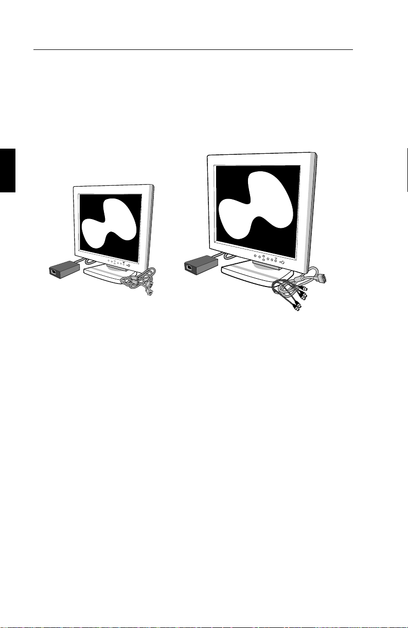
Contents of Package
Your new MultiSync LCD monitor box should contain the following:
MultiSync LCD1510 / LCD1510V
monitor with Video Signal Cable
and AC Adapter
MultiSync LCD2010 monitor
with 15-pin VGA to BNC Cable
and AC Adapter
– NEC MultiSync LCD1510 (Model LA-152lJMW)/
NEC MultiSync LCD
NEC MultiSync LCD
1510V (Model LA-1522JMW).
2010 (Model LA-2032JMW).
– AC power cable.
– AC Adapter
– Video Signal Cable – 15 pin VGA to 15 pin mini D-SUB
1510 / LCD1510V).
(LCD
Video Signal Cable – 15 pin VGA to BNC (LCD
2010).
– User’s manual.
Remember to save the original box and packing materials to transport or
ship the monitor.
Page 20

Recommended Use E - 5
Recommended Use
For optimum performance, please note the following when setting up
and using the MultiSync LCD
DO NOT OPEN THE MONITOR. There are no user
•
serviceable parts inside and opening or removing covers may
expose you to dangerous shock hazards or other risks. Refer
all servicing to qualified service personnel.
The optimum monitor position is facing away from direct
•
sunlight.
Allow adequate ventilation around the monitor so that heat can
•
properly dissipate. Do not block ventilated openings or place
the monitor near a radiator or other heat sources. Do not put
anything on top of monitor.
Do not spill any liquids into the cabinet or use your monitor
•
near water.
1510 / LCD1510V / LCD2010 colour monitor:
Do not insert objects of any kind into the cabinet slots, as they
•
may touch dangerous voltage points, which can be harmful or
fatal or may cause electric shock, fire or equipment failure.
Do not place any heavy objects on the power cord. Damage to
•
the cord may cause shock or fire.
Do not place this product on a sloping or unstable cart, stand or
•
table, as the monitor may fall, causing serious damage to the
monitor.
Use the monitor in a clean and dry area.
•
Handle with care when transporting. Save packaging for
•
transporting.
The power cable connector is the primary means of detaching
•
the system from the power supply. The monitor should be
installed close to a power outlet which is easily accessible.
Page 21

E - 6 Recommended Use
Use supplied AC Adapter.
•
The inside of the fluorescent tube located within the LCD
•
monitor contains mercury. Please follow the bylaws or rules of
your local municipality to dispose of this tube property.
Clean the LCD monitor surface with a lint-free, non-abrasive
•
cloth. Avoid using any cleaning solution, glass cleaner or tissue
paper.
For optimum performance, allow 20 minutes for warm-up.
•
Avoid displaying fixed patterns on the monitor for long periods
•
of the time to avoid image persistence (after-image effects.)
Avoid applying pressure to the LCD monitor surface.
•
Immediately unplug your monitor from the wall outlet and refer servicing
to qualified service personnel under the following conditions:
When the power supply cord or plug is damaged.
•
If liquid has been spilled or objects have fallen into the monitor.
•
If the monitor has been exposed to rain or water.
•
If the monitor has been dropped or the cabinet is damaged.
•
If the monitor does not operate normally by following operating
•
instructions.
Page 22

Recommended Use E - 7
CORRECT PLACMENT AND ADJUSTMENT OF THE MONITOR
CAN REDUCE EYE, SHOULDER AND NECK FATIGUE. CHECK
THE FOLLOWING WHEN YOU POSITION THE MONITOR:
Adjust the monitor height so that the top of the screen is at or
•
slightly below eye level. Your eyes should look slightly
downward when viewing the middle of the screen.
Position your monitor no closer than 40 cm and no further away
•
than 70 cm from your eyes. The optimal distance of MultiSync
LCD
1510 / LCD1510V is 53 cm, MultiSync LCD2010 is 61 cm.
Rest your eyes periodically by focusing on an object at least
•
6 m away.
Position the monitor at a 90° angle to windows and other
•
light sources to minimize glare and reflections. Adjust the
monitor tilt so that ceiling lights do not reflect on your screen.
If reflected light makes it hard for you to see your screen, use
•
an anti-glare filter.
Adjust the monitor’s brightness and contrast control to enhance
•
readability.
Use a document holder placed close to the screen.
•
Position whatever you are looking at most of the time (the screen
•
or reference material) directly in front of you to minimize
turning your head while you are typing.
Get regular eye checkups.
•
Page 23

E - 8 Installation
Installation
Connection to your Personal Computer
The MultiSync LCD1510 / LCD1510V / LCD2010 true colour monitor
complements PC compatible computers. Your system has one of two
configurations:
– the video controller is built into the computer.
– the video controller is in the form of a display card (sometimes
referred to as graphics card, video adapter or graphics board).
Both configurations have a video connector (or a CRT PORT on laptop
computers). If you are not sure which connector is the video connector,
refer to your computer or display card manual.
To attach the monitor to your system, follow these instructions:
1. Turn off the power to the monitor and computer.
2. If necessary, install the display card. For more information about
installing your card, refer to the display card manual.
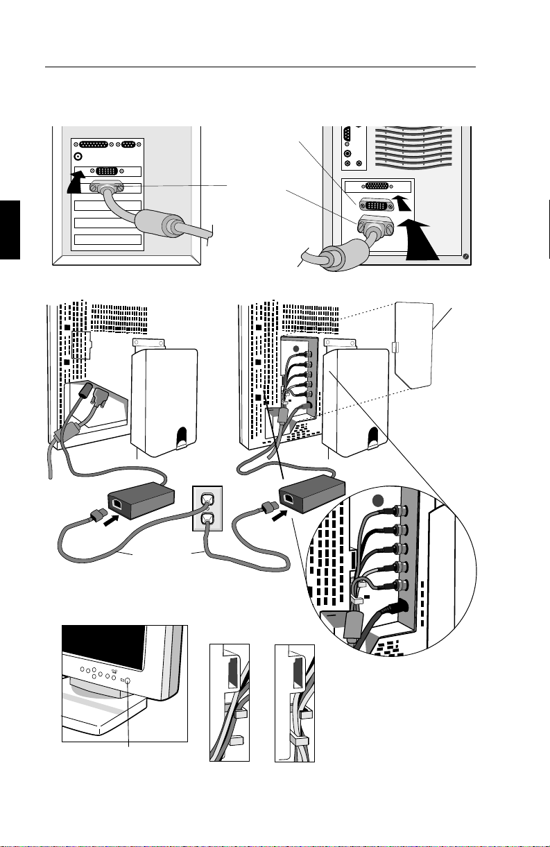
3. Connect the 15-pin mini D-SUB of the appropriate signal
cable to the connector of the display card in your computer.
Tighten all screws (Figure A.1).
4. For the MultiSync LCD
1510, MultiSync LCD1510V: Connect
the 15-pin mini D-SUB of the video signal cable and the AC
Adapter cable to the appropriate connectors on the back of the
monitor (Figure C.1).
For the MultiSync LCD
2010: Remove connector cover on back
of monitor. Connect the BNC cables and AC adapter cable to
the appropriate connectors on the back of the monitor. Connect
the red BNC cable to the BNC connector on the monitor labeled
R, the green BNC cable to the BNC connector labeled G/Sync,
the blue BNC cable to the BNC connector labeled B. If you
have a fourth BNC connector (Composite Sync), connect it to
the BNC connector on the monitor labeled H/CS. If you have a
fifth BNC connector (Vertical Sync), connect it to the BNC
Page 24

Installation E - 9
connector on the monitor labeled VS (Figure D.1).
Place the 15-pin VGA to BNC cable and the AC adapter cable
under Clip A (Figure D.1A). Then place the 15-pin VGA to
BNC cable and the AC adapter cable under Clip B (Figure
D.1B). Replace connector cover.
Note: Incorrect cable connections may result in irregular operation,
damage display quality/components of LCD module and/or shorten the
module’s life.
5. Connect one end of the power cord to the AC Adapter and the
other end to the power outlet (Figure E.1).
6. Turn on the monitor (Figure F.1) and the computer.
7. To complete the setup of your MultiSync LCD monitor, use
the following OSM controls:
• Auto Adjust Contrast
• Auto Adjust
• Image Adjust – Fine (MultiSync LCD
2010 monitor only)
NOTE: Manual adjustment of the H/V Position and Image Adjust H
Size / Fine controls may be required to complete setup of your MultiSync
monitor. For a full description of these OSM controls, refer to the
Controls section of this User’s Manual.
NOTE: If you have any problems, please refer to the Troubleshooting
section of this User’s Manual.
Page 25
E - 10 Installation
Mac Adapter
(not included)
15-pin
mini D-SUB
Figure C.1
Figure A.1 Figure B.1
MultiSync
LCD
1510
monitor
MultiSync
LCD
Power Cord
Figure E.1
Figure F.1
Figure D.1A
Figure D.1B
Figure D.1
2010
Connector
Cover
monitor
Power Switch
Page 26

Installation E - 11
Connection to your Personal Computer (Macintosh)
With the Macintosh cable adapter, the MultiSync LCD1510 / LCD1510V
/ LCD2010 colour monitor is compatible with the Macintosh family of
computers. You will connect your MultiSync colour monitor one of
two ways to your Macintosh computer:
– On-board video port1
– NuBus/PCI/PDS display card
Both configurations should have the same style video connector. If you
are not sure which port is the monitor connector, please reference your
computer or display card manual.
To attach your MultiSync LCD monitor to your system, follow these
instructions:
1. Turn off the power to your MultiSync LCD monitor and
Macintosh.
2. If neccssary, install the display card. For more information on
this installation, reference the display card manual.
3. Connect the MultiSync LCD
MultiSync LCD
2010 Macintosh cable adapter to the computer
1510, MultiSync LCD1510V or
(Figure B.1). Attach the 15-pin mini D-SUB end of the
appropriate signal cable to the MultiSync LCD
LCD
1510V or MultiSync LCD2010 Macintosh cable adapter
1510, MultiSync
(Figure B.1). Tighten all screws.
4. For the MultiSync LCD1510, MultiSync LCD1510V: Connect
the 15-pin mini D-SUB of the video signal cable and the AC
Adapter cable to the appropriate connectors on the back of the
monitor (Figure C.1).
For the MultiSync LCD
2010: Remove connector cover on back
of monitor. Connect the BNC cables and AC adapter cable to
the appropriate connectors on the back of the monitor. Connect
the red BNC cable to the BNC connector on the monitor labeled
R, the green BNC cable to the BNC connector labeled G/Sync,
the blue BNC cable to the BNC connector labeled B. If you
have a fourth BNC connector (Composite Sync), connect it to
Page 27

E - 12 Installation
the BNC connector on the monitor labeled H/CS. If you have a
fifth BNC connector (Vertical Sync), connect it to the BNC
connector on the monitor labeled VS (Figure D.1).
Place the 15-pin VGA to BNC and AC adapter cable under
Clip A(Figure D.1A). Then place the 15-pin VGA to BNC and
AC adapter cable under Clip B(Figure D.1B). Replace
connector cover.
NOTE: Incorrect cable connections may result in irregular operation,
damage display quality/components of LCD module and/or shorten the
module’s life.
5. Connect one end of the power cord to the AC Adapter and the
other end to the power outlet (Figure E.1).
6. Turn on the monitor (Figure F.1) and the computer.
7. To complete the setup of your MultiSync LCD monitor, use
the following OSM controls:
• Auto Adjust Contrast
• Auto Adjust
• Image Adjust – Fine (MultiSync LCD
2010 monitor only)
NOTE: Manual adjustment of the H/V Position and Image Adjust
H. Size / Fine controls may be required to complete setup of your
MultiSync monitor. For a full description of these OSM controls, refer
to the Controls section of this User’s Manual.
NOTE: If you have any problems, please refer to the Troubleshooting
section of this User’s Manual.
Please contact your local dealer for information about the Mac Adapter.
Page 28

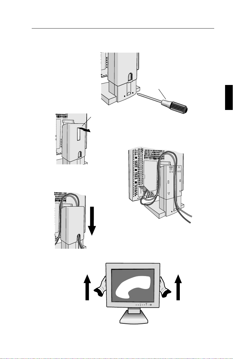
Installation E - 13
Shipping Screws
Loosen the two shipping screws (Figure SS.1). (The screws will not
come out. Turn them until they are loosened completely.) If the screws
are loosened correctly only the screen will rise up when lifting the
cabinet. (Refer to figure RL.1).
If the unit needs to be repackaged for shipping, make sure monitor is in
lowest Landscape position, then retighten the shipping screws in order
to protect the internal parts.
Cable Management
To use the cable management feature, lift up then remove back cover
(Figure CM.1). Place all cables into the vertical groove, leaving 15cm
to 25cm of slack in the cables to allow the monitor to rotate between
Landscape and Portrait orientation (Figure CM.2). To replace back cover,
push in then slide down (Figure CM.3).
Raise and Lower Monitor Screen
The monitor may be raised or lowered in either Portrait or Landscape
mode. To raise screen, place hands on each side of the monitor and lift
to the desired height (Figure RL.1). To lower screen, place one hand
under bottom of screen, lift slightly (Figure RL.2) and simultaneously
push the button on the bottom back of the stand (Figure RL.3). Screen
will lower while button is pushed in.
Release button to lock screen in place.
CAUTION: Although the monitor has been designed not to lower
automatically when the button is pushed, ALWAYS support the bottom
of the screen with one hand.
Page 29

E - 14 Installation
Screen Rotation
Before rotating, the screen must be raised to the highest level to avoid
knocking the screen on the desk or pinching your fingers.
To raise the screen, place hands on each side of the monitor and lift up
(Figure R.1).
To rotate screen, place hands on each side of the monitor screen and
turn clockwise from Landscape to Portrait or counter-clockwise from
Portrait to Landscape (Figure R.2).
To toggle the orientation of the OSM menu between Landscape and
Portrait modes, press the RESET button while OSM menu is off.
Tilt and Swivel
Grasp both sides of the monitor screen with your hands and adjust the
tilt and swivel as desired (Figure TS.1).
Page 30
Installation E - 15
Phillips head
screwdriver
Figure SS.1
Cable Cover
Lift up then remove
back cover
Leave sufficient
length of cable
Figure CM.1
Figure CM.3
Figure CM.2
Push in and slide down
Figure RL.1
Page 31

E - 16 Installation
Figure RL.2 Figure RL.3
Figure R.1
Figure R.2
Figure TS.1
Page 32

Installation E - 17
Remove Monitor Stand for Mounting
To prepare the monitor for alternate mounting purposes:
1. Disconnect all cables.
2. Place hands on each side of the monitor screen and raise it to
the maximun height (Figure R.1).
3. Place monitor face down on a non-abrasive surface (Place the
screen on a 40mm platform so that the stand is parallel with
the surface.) (Figure S.1).
40mm
Figure S.1
4. Remove cable cover. Remove the 4 screws connecting the monitor
to the stand and lift off the stand assembly (Figure S.2).
The monitor is now ready for mounting in an alternate manner.
5. Reverse this process to reattach stand.
NOTE: Use only VESA-compatible alternative mounting method.
4
3
2
1
Figure S.2
Page 33

E - 18 Controls
Controls
OSM Controls
OSM
The OSM controls on the front of the monitor provide the following
functions:
To access OSM press any of the control buttons ( , , , ) or the PROCEED or
EXIT button.
To rotate OSM between Landscape and Portrait modes, press the RESET button.
Main Menu Sub-Menu
EXIT Exits the OSM controls. Exits to the OSM main
menu.
CONTROL / Moves the highlighted Moves the highlighted
area up/down to select area up/down to select
one of the controls one of the controls
CONTROL / Moves the highlighted area Moves the bar left /
left / rights to select right to increase or
control menus. decrease the adjustment.
PROCEED Has no function. Activates Auto Adjust
and ALL RESET functions.
RESET Resets the highlighted Resets the highlighted
contol menu to the factory contol to the factory
setting. setting.
NOTE: When RESET is pressed in the main and sub-menu, a warning window will
appear allowing you to cancel the RESET function by pressing the EXIT button.
Page 34

Controls E - 19
Brightness/Contrast Controls
BRIGHTNESS
Adjusts the overall image and background screen brightness.
CONTRAST
Adjusts the image brightness in relation to the background.
AUTO ADJUST CONTRAST
Adjusts the image displayed for non-standard video inputs.
Auto Adjust
MultiSync LCD1510, LCD1510V monitor only
Automatically adjusts the Image Position, the H. Size or
Fine settings.
MultiSync LCD
Automatically adjusts the Image Position or the H. Size
setting.
NOTE: Manual adjustment of the H/V Position and Image Adjust
H. Size / Fine controls may be required to complete setup of
your MultiSync monitor.
2010 monitor only
Position Controls
H. POSITION
Controls Horizontal Image Position within the display area
of the LCD.
V. POSITION
Controls Vertical Image Position within the display area of
the LCD.
AUTO
Automatically sets the Horizontal and Vertical Image
Position within the display area of the LCD.
Page 35

E - 20 Controls
Image Adjust Controls
H. SIZE
Adjusts the horizontal size by increasing or decreasing the
this setting.
FINE
Improves focus, clarity and image stability by increasing or
decreasing this setting.
NOTE: The Image Adjust Fine control must be used to
complete the setup of your MultiSync LCD
2010 monitor.
MultiSync LCD
1510, MultiSync LCD1510V monitor only
Automatically adjusts the H. Size or Fine settings.
MultiSync LCD2010 monitor only
Automatically adjusts the H. Size settings.
Colour Control System
Five colour presets select the desired colour setting. Each
colour setting is adjusted at the factory.
R,G,B: Increases or decreases Red, Green or Blue colour
depending upon which is selected. The change in colour will
appear on screen and the direction (increase or decrease)
will be shown by the bars.
Tools
OSM H. POS.
OSM V. POS.
You can choose where you would like the OSM control
window to appear on your screen. Selecting OSM Location
allows you to manually adjust the position of the OSM
control menu left, right, up or down.
ALL RESET
Selecting ALL RESET allows you to reset all OSM control
settings back to the factory settings. Individual settings can
be reset by highlighting the control to be used and pressing
the RESET button.
Page 36

Controls E - 21
Information
Indicates the current display resolution, frequency setting
and type of Sync signal of the monitor.
NOTE: Mode Change should only be used if a resolution is
not recognized by the monitor. The user can change to the
appropriate resolution by selecting the Mode information
and selecting (increase or decrease) the corresponding option.
NOTE: If the or button is pressed while TYPE is
highlighted, then Sync Type is switched between Separate
Sync and Sync On Green.
OSM LOCK OUT
The OSM LOCK OUT control completely locks out access
to all OSM control functions. When attempting to activate
OSM controls while in the LOCK OUT mode, a screen will
appear indicating that OSM controls are locked out.
• To enter the LOCK OUT mode, simultaneously press
the PROCEED and button. The LOCK OUT window
will appear.
• To activate the LOCK OUT function, simultaneously
press and hold down the PROCEED and button. The
OSM window will disappear within seconds and the
LOCK OUT function will be activated.
• To deactivate the LOCK OUT mode, simultaneously
press the PROCEED and button.
Page 37

E - 22 Specifications
Specifications
MultiSync LCD1510 / LCD1510V
Display 1510: 38 cm (15 inch) viewable image size; 1024 x 768
native resolution (Pixel Count); active matrix;
thin film transistor (TFT); liquid crystal display (LCD);
0.297 mm dot pitch; 180 cd/m
100:1 contrast ratio, typical
1510V: 38 cm (15 inch) viewable image size; 1024 x 768
native resolution (Pixel Count); active matrix;
thin film transistor (TFT); liquid crystal display (LCD);
0.297 mm dot pitch; 200 cd/m
200:1 contrast ratio, typical
Input Signal Video Analog 0.7 Vp-p 75 Ω
Sync Separate sync. TTL Level
Horizontal sync. Positive/Negative
Vertical sync. Positive/Negative
Composite sync. (Positive/Negative)
(TTL Level)
Sync on Green video (Positive) 0.7
Vp-p and sync. Negative 0.3 Vp-p
2
white luminance, typical;
2
white luminance, typical;
Display Colours Analog Input: Unlimited number of colours
(Depends on the graphics board)
Synchronisation Horizontal 24.8 kHz to 60.0 kHz (Automatically)
Range
Vertical 56.2 Hz to 85.1 Hz (Automatically)
Resolutions Landscape 720 x 400: VGA text*
Supported 640 x 480 at 60 Hz to 85 Hz*
800 x 600 at 56 Hz to 85 Hz*
832 x 624 at 75 Hz*
1024 x 768 at 60 Hz to 75 Hz**
Portrait 480 x 600 at 60 Hz to 85 Hz*
600 x 800 at 56 Hz to 85 Hz*
624 x 832 at 75 Hz*
768 x 1024 at 60 Hz to 75 Hz**
Page 38

Specifications E - 23
Active Display Landscape Horizontal 304 mm
Area*** Vertical 228 mm
Portrait Horizontal 228 mm
Vertical 304 mm
Power supply AC 100-120 V / 220-240 V 50/60 Hz
Current Rating LCD1510
LCD1510V
0.7 A @ 100-120 V / 0.4 A @ 220-240 V
0.5 A @ 100-120 V / 0.3 A @ 220-240 V
Dimensions Landscape 381mm(W) x 392mm(H) x 217mm(D)
Portrait 312mm(W) x 427mm(H) x 217mm(D)
Hight Adjust 55mm
Weight LCD1510 7.0 kg
LCD1510V 6.7 kg
Operating Temperature 5° C to + 35° C
Environmental
Considerations
Humidity 30% to 80%
Storage Temperature -10° C to + 60° C
Environmental
Considerations
* Interpolated Resolutions: when resolutions are shown that are lower than the pixel
count of the LCD module, text may appear choppy or lines may appear to be bold. This
is normal and necessary for all current flat panel technologies, each dot on the screen is
actually one pixel, so to expand resolutions to full screen, an interpolation of the resolution
must be done. When the interpolated resolutions is not an exact multiple of the native
resolution, the mathematical interpolation necessary may cause some lines to appear
thicker than others.
** NEC cites recommended resolutions at 75 Hz for optimal display performance.
*** Active display area is dependent upon the signal timing.
Humidity 10% to 85%
Technical specifications are subject to change without notice.
Page 39

E - 24 Specifications
Multisync LCD2010
Display 51.1 cm (20.1 inch) viewable image size; 1280 x 1024
native resolution (Pixel Count); active matrix;
thin film transistor (TFT); liquid crystal display (LCD);
0.31 mm dot pitch; 150 cd/m
150:1 contrast ratio, typical
Input Signal Video Analog 0.7 Vp-p 75 Ω
Sync Separate sync. TTL Level
Horizontal sync. Positive/Negative
Vertical sync. Positive/Negative
Composite sync. (Positive/Negative)
(TTL Level)
Sync on Green video (Positive) 0.7
Vp-p and sync. Negative 0.3 Vp-p
Display Colours Analog Input: Unlimited number of colours
(Depends on the graphics board)
Synchronisation Horizontal 24.0 kHz to 80.0 kHz (Automatically)
Range Vertical 56.0 Hz to 76.0 Hz (Automatically)
2
white luminance, typical;
Resolutions Landscape 720 x 400: VGA text*
Supported 640 x 480 at 60 Hz to 76 Hz
800 x 600 at 56 Hz to 76 Hz*
832 x 624 at 75 Hz*
1024 x 768 at 60 Hz to 76 Hz*
1280 x 960 at 60 Hz to 76 Hz
1280 x 1024 at 60 Hz to 76 Hz**
Portrait 480 x 640: at 60Hz to 76Hz
600x 800 at 56 Hz to 76 Hz*
624 x 832 at 75 Hz*
768 x 1024 at 60 Hz to 76 Hz*
960 x 1280 at 60 Hz to 76 Hz*
1024 x 1280 at 60 Hz to 76 Hz**
Active Display Landscape Horizontal 399 mm
Area*** Vertical 319 mm
Portrait Horizontal 319 mm
Vertical 399 mm
Page 40

Specifications E - 25
Power supply
AC 100-120 V / 220-240 V @ 50/60 Hz
Current Rating 1.0A @ 100-120V / 0.5A @ 220-240V
Dimensions Landscape 498(W) x 501(H) x 262(D) mm
Portrait 418(W) x 541(H) x 262(D) mm
Hight Adjust 80mm
Weight 12.5kg
Operating Temperature 5° C to + 30° C
Environmental
Considerations
Humidity 30% to 80%
Storage Temperature -10° C to + 60° C
Environmental
Considerations
* Interpolated Resolutions: when resolutions are shown that are lower than the pixel
count of the LCD module, text may appear choppy or lines may appear to be bold. This
is normal and necessary for all current flat panel technologies, each dot on the screen is
actually one pixel, so to expand resolutions to full screen, an interpolation of the resolution
must be done. When the interpolated resolutions is not an exact multiple of the native
resolution, the mathematical interpolation necessary may cause some lines to appear
thicker than others.
** NEC cites recommended resolutions at 60 Hz for optimal display performance.
*** Active display area is dependent upon the signal timing.
Humidity 10% to 85%
Technical specifications are subject to change without notice.
Page 41

E - 26 Troubleshooting/Support
Troubleshooting/Support
Problem Check These Items
No picture - The signal cable should be completely connected to
the display card/computer.
- The display card should be completely seated in its
slot.
- Power button and computer power switch should be
in the ON position.
- Check to make sure that a supported mode has been
selected on the display card or system being used.
(Please consult display card or system manual to
change graphics mode.)
- Check the monitor and your display card with respect
to compatibility and recommended settings.
- Check the signal cable connector for bent or pushedin pins.
Power Button does Unplug the power cord of the monitor from the AC
not respond outlet to turn off and reset the monitor, or simultaneously
press the RESET and Power buttons.
Image persistence Image persistence is when a “ghost” of an image
remains on the screen even after the monitor has been
turned off. Unlike CRT monitors, LCD monitors’
image persistence is not permanent. To alleviate image
persistence, turn the monitor off for as long as an image
was displayed. If an image was on the monitor for one
hour and a ”ghost” of that image remains, the monitor
should be turned off for one hour to erase the image.
NOTE: As with all personal display devices, NEC
recommends using a screen saver at regular intervals
whenever the screen is idle.
Page 42

Troubleshooting/Support E - 27
Problem Cheak These Items
Image is unstable, - Signal cable should be completely attached to the
unfocused or computer.
swimming is - Use the OSM Image Adjust controls to focus and
apparent adjust display by increasing or decreasing the Fine Control.
When the display mode is changed, the OSM Image
Adjust settings may need to be re-adjusted.
- Check the monitor and your display card with respect
to compatibility and recommended signal timings.
- If your text is garbled, change the video mode to non
-interlace and use 60Hz refresh rate.
LED on monitor is - Power Switch should be in the ON position and power
not lit (no green or cord should be connected.
amber colour can be - Make certain the computer is not in a power-saving
seen) mode (touch the keyboard or mouse).
Display image has a Select “TYPE” in the OSM Information menu
and
green cast to it press the or Control button.
Display image is not - Use the OSM Image Adjust controls to increase or
sized properly decrease the H. Size.
- Check to make sure that a supported mode and signal
timing has been selected on the display card or system
being used. (Please consult display card or system
manual to change graphics mode or refresh rate.)
Selected resolution Select the Display Resolution in the OSM Information
is not displayed menu
confirm that the appropriate resolution has
properly been selected. If not, select corresponding option.
by pressing the or Control button.
Page 43

Page 44

Deutsch
Page 45

Page 46

Vorstellung des NEC MultiSync LCD
1510
/ LCD
1510V
/ LCD
2010
D - 1
Vorstellung des NEC MultiSync LCD1510 / LCD1510V / LCD2010
Herzlichen Glückwunsch zum Kauf Ihres NEC MultiSync LCD1510/
LCD
1510V/LCD2010 Farbmonitors.
Weitwinkel-Technologie
(nur MultiSync LCD1510 und MultiSync LCD2010)
Diese Technologie ermöglicht die Betrachtung des Bildes (Hoch- und
Querformat) aus jedem beliebigen Winkel (160 Grad) des Raumes. Der
Betrachtungswinkel beträgt nach oben, unten, links und rechts volle 160°.
Analog ist besser
Der MultiSync LCD1510 / LCD1510V / LCD2010 kann eine unbegrenzte
Zahl an Farben in einem unendlichen Spektrum naturgetreu darstellen.
Der sehr hohe Kontrastumfang erhöht die Farbbrillanz und verbessert
die Bildschärfe ohne dabei die Bildgeometrie zu beeinflussen.
Größere Kompatibilität
Der MultiSync LCD1510 / LCD1510V / LCD2010 ist durch und durch ein
analoger Monitor.
Mit dem analogen Interface ist ein Anschluß an spezielle Grafik- bzw.
Interface-Karten nicht erforderlich, sondern der LCD Monitor kann direkt
über die RGB-Signale arbeiten.
Minimierte Stellfläche
Die ideale Lösung auch für kleineste Bildschirmarbeitsplätze hervorragende Bildqualität bei minimaler Bildschirmgröße und geringem
Bildschirmgewicht. Der geringe Platzbedarf und das geringe Gewicht
ermöglichen den problemlosen Transport des Gerätes von einer
Einsatzstelle zur nächsten.
Page 47

D - 2 Vorstellung des NEC MultiSync LCD1510 / LCD1510V / LCD2010
Farbeinstellungsmenü (ColorControl System)
Über das ColorControl System können die Farben Ihres Bildschirmes
exakt eingestellt und die Farbintensität einer Vielzahl von Anforderungen
angepaßt werden.
OSM (On Screen Manager)
Der On Screen Manager erlaubt eine direkte, menügesteuerte Einstellung
individueller Bildparameter.
Ergonomisches Design
Das ergonomische Design verbessert die Arbeitsumgebung im Sinne
der menschlichen Bedürfnisse, schützt die Gesundheit des Benutzers
und ermöglicht finanzielle Einsparungen. Als Beispiele seien hier die
optimale Einstellung der der Bildqualität per On Screen Manager (OSM),
der neue Standfuss, der Drehen, Schwenken und Neigen des Schirms
für optimalen Blickwinkel erlaubt, die geringe Stellfläche und die
Zertifizierung nach TCO genannt.
Drehbares Untergestell
Mit Hilfe des drehbaren Untergestells kann der Benutzer den Bildschirm
entsprechend individueller Erfordernisse ausrichten. Querformat für
breite Dokumente oder Hochformat, um sich eine Seite auf dem
Bildschirm im ganzen anzusehen. Das Hochformat eignet sich darüber
hinaus bestens für Vollbild-Videokonferenzen.
Plug & Play (nur LCD1510 / LCD1510V)
Plug & Play ist die in Windows integrierte Antwort von Microsoft bei
der Einrichtung und Installation von Peripheriegeräten. Der Monitor teilt
seine Leistungsmerkmale (wie z.B. Bildschirmgröße und Auflösung)
direkt Ihrem Computer mit, so daß von diesem automatisch das
bestmögliche Bild eingestellt wird.
Page 48

Vorstellung des NEC MultiSync LCD1510 / LCD1510V / LCD2010 D - 3
IPM-System (Intelligent PowerManager)
Der Intelligent PowerManager (intelligenter Energieverwalter) ist eine
fortschrittliche Einrichtung zum Energiesparen. Bei Arbeitspausen am
LCD-Monitor werden 2/3 an Energie und Kosten eingespart, Emissionen
reduziert und der Sauerstoffverbrauch am Arbeitsplatz wird niedriger.
Multi-Frequenz-Technologie
Die Multi-Frequenz-Technologie hat die Eigenschaft, daß die horizontale
und vertikale Frequenz bei allen Bildschirmauflösungen automatisch
eingestellt wird.
FullScan
FullScan hat die Eigenschaft, bei allen Bildschirmauflösungen immer
die maximale Bildschirmfläche zu nutzen.
VESA-Standardschnittstelle
Über diese Schnittstelle kann der MultiSync-Monitor an jeden VESAStandard-Montagearm bzw. Montagerahmen angeschlossen werden.
Der Monitor kann an der Wand oder zur Benutzung an umliegenden
Arbeitsplätzen an einem Arm installiert werden.
Page 49

D - 4 Lieferumfang
Lieferumfang
Die folgende Übersicht zeigt den Lieferumfang Ihres neuen MultiSync
LCD Monitors:
MultiSync LCD1510 / LCD1510V
Monitor mit Videosignalkabel und
AC-Adapter.
MultiSync LCD2010 Monitor mit
Videosignalkabel - 16 Pin VGA
auf BNC - und AC-Adapter.
– NEC MultiSync LCD1510 (Modell LA-1521JMW)
NEC MultiSync LCD
NEC MultiSync LCD
1510V (Modell LA-1522JMW)
2010 (Modell LA-2032JMW)
– AC-Netzkabel
– Videosignalkabel – 15 Pin VGA auf 15 Pin Mini D-SUB
1510 / LCD1510V)
(LCD
Videosignalkabel – 15 Pin VGA auf BNC (LCD
2010)
– Bedienerhandbuch
Karton und Verpackungsmaterial sollten Sie für einen späteren Transport
bzw. Versand Ihres LCD Monitors aufbewahren.
Page 50

Empfehlungen zur Benutzung D - 5
Empfehlungen zur Benutzung
Um eine optimale Leistungsfähigkeit Ihres LCD1510 / LCD1510V /
LCD
2010 Farbmonitors zu gewährleisten, sollten die nachfolgend
aufgeführten Punkte bei der Aufstellung Ihres neuen Gerätes beachtet
werden:
ÖFFNEN SIE DEN MONITOR NICHT. Im Inneren des
•
Gerätes befinden sich keine Teile, die vom Benutzer selbst
gewartet werden können. Das Öffnen oder Entfernen der
Abdeckungen könnte einen elektrischen Schlag verursachen
oder zu anderen gefährlichen Situationen führen.
Reparaturarbeiten dürfen nur von qualifiziertem technischem
Personal durchgeführt werden.
Plazieren Sie den Monitor nicht an Orten, an denen er direktem
•
Sonnenlicht ausgesetzt wäre.
Achten Sie auf eine ausreichende Rundum-Belüftung des
•
Monitors, damit die Wärme richtig entweichen kann. Die
Lüftungsschlitze dürfen nicht blockiert sein und der Monitor
darf nicht in der Nähe einer Heizung oder sonstigen
Wärmequelle aufgestellt werden. Stellen Sie keine Gegenstände
auf den Monitor.
Vermeiden Sie das Eindringen von Flüssigkeiten in das Gerät
•
und benutzen Sie den Monitor niemals in der Nähe von Wasser.
Stecken Sie keinerlei Gegenstände in das Gerät. Diese könnten
•
gefährliche Spannungspunkte im Geräteinneren berühren und
einen elektrischen Schlag, Brand oder Fehlfunktionen des
Gerätes verursachen.
Stellen Sie keine schweren Gegenstände auf das Netzkabel.
•
Eine Beschädigung des Netzkabels kann einen elektrischen
Schlag oder Brand verursachen.
Stellen Sie dieses Gerät niemals auf einer unebenen, instabilen
•
Unterlage auf. Der Monitor könnte herunterfallen und schwer
beschädigt werden.
Page 51

D - 6 Empfehlungen zur Benutzung
Benutzen Sie den Monitor nur in sauberer und trockener
•
Umgebung.
Transportieren Sie den Monitor mit äußerster Vorsicht.
•
Bewahren Sie das Verpackungsmaterial für einen
möglicherweise erneuten Transport auf.
Der Netzstecker ist das wichtigste Teil beim Abtrennen des
•
Monitors vom Netz. Das Gerät sollte in der Nähe einer leicht
zugänglichen Netzsteckdose installiert werden.
Benutzen Sie den mitgelieferten AC-Adapter.
•
Die sich im Inneren des LCD Monitors befindliche
•
Fluoreszenzröhre beinhaltet Quecksilber. Bitte beachten Sie
bei der Entsorgung der Röhre die in Ihrem Land geltenden
Gesetze und Vorschriften.
Reinigen Sie den LCD Monitor mit einem fusselfreien und nicht
•
kratzendem Tuch. Verwenden Sie für die Reinigung keine
Reinigungsmittel, Glasreiniger oder Papiertücher.
Zur Gewährleistung einer optimalen Leistungsfähigkeit sollte
•
die Aufwärmphase vor der Inbetriebnahme des Gerätes ca. 20
Minuten betragen.
Vermeiden Sie die Darstellung statischer Bildinformationen
•
über einen längeren Zeitraum hinweg, da sonst ein
Erhaltungseffekt der Bildinformation bei den Flüssigkristallen,
landläufig als Einbrennen bezeichnet, auftritt. Dieser Effekt
ist allerdings, im Gegensatz zu Bildröhren, reversibel.
Vermeiden Sie Druckeinwirkungen auf die Oberfläche des LCD
•
Monitors.
Unter den nachfolgend aufgeführten Umständen muß der Monitor sofort
vom Netz getrennt und ein Service-Techniker konsultiert werden:
Wenn das Netzkabel oder der Netzstecker beschädigt sind.
•
Falls Flüssigkeiten verschüttet wurden oder Gegenstände in
•
das Monitorgehäuse gefallen sind.
Wenn das Gerät Regen ausgesetzt war oder mit Wasser in
•
Berührung gekommen ist.
Page 52

Empfehlungen zur Benutzung D - 7
Wenn das Gerät bei Bedienung entsprechend des
•
Bedienerhandbuches nicht ordnungsgemäß funktioniert.
DAMIT AUGEN, NACKEN- UND SCHULTERMUSKULATUR
BEIM ARBEITEN AM BILDSCHIRM ENTLASTET WERDEN,
BEACHTEN SIE BEIM AUFSTELLEN UND EINSTELLEN IHRES
MONITORS BITTE DIE NACHFOLGEND AUFGEFÜHRTEN
HINWEISE:
Falls der Monitor trotz korrekter Anwendung der folgenden
•
Installationsanleitung nicht normal arbeitet.
Der Abstand vom Auge zum Monitor sollte nicht weniger als
•
40 cm und nicht mehr als 70 cm betragen. Der optimale Abstand
beträgt beim MultiSync LCD
LCD
2010 61 cm.
Entspannen Sie Ihre Augen regelmäßig durch Fixieren eines
•
Gegenstandes in mindestens 6 m Abstand. Blinzeln Sie oft mit
den Augen.
1510 / LCD1510V 53 cm und beim
Stellen Sie den Monitor in einem Winkel von 90° zum Fenster
•
und anderen Lichtquellen auf, damit Blendungen und
Reflexionen auf dem Bildschirm soweit wie möglich vermieden
werden. Stellen Sie den Schwenk-/Neigefuß Ihres Monitors so
ein, daß durch Deckenbeleuchtung verursachte Spiegelungen
auf dem Bildschirm vermieden werden.
Wenn reflektierendes Licht die Erkennbarkeit Ihres Monitors
•
erschwert, benutzen Sie einen Anti-Reflexionsfilter.
Stellen Sie die Helligkeit und den Kontrast so ein, daß die
•
Lesbarkeit des Bildschirms erhöht ist.
Bringen Sie in der Nähe des Monitors einen Vorlagenhalter
•
an.
Plazieren Sie das, auf das Sie am meisten schauen (Bildschirm
•
oder Referenzmaterial) direkt vor sich, damit Sie den Kopf beim
Schreiben so wenig wie möglich drehen müssen.
Lassen Sie Ihre Augen regelmäßig vom Augenarzt untersuchen.
•
Page 53

D - 8 Installation
Installation
Anschluß an Ihren PC
Der MultiSync LCD1510 / LCD1510V / LCD2010 Farbmonitor ist für den
Einsatz an PC kompatiblen Computern ausgelegt. Ihr System verfügt
über eine von zwei möglichen Konfigurationen:
– die Videosteuerung ist in Ihrem Computer installiert
– die Videosteuerung ist eine Display-Karte (wird häufig als
Grafikkarte, Videoadapter oder Grafiktafel bezeichnet)
Beide Varianten haben einen Videoanschluß (oder ein CRT PORT bei
Laptops). Sollten Sie nicht sicher sein, welcher Anschluß der
Videoanschluß ist, beziehen Sie sich bitte auf das Bedienerhandbuch
Ihres Computers oder der Display-Karte.
Zum Anschluß des Monitors an das System verfahren Sie bitte wie folgt:
1. Schalten Sie die Stromversorgung vom Computer und Monitor
aus.
2. Installieren Sie, falls erforderlich, die Display-Karte.
Einzelheiten bezüglich der Installation entnehmen Sie bitte dem
mit der Display-Karte mitgelieferten Bedienerhandbuch.
3. Schließen Sie das 15-Pin Mini D-SUB Signalkabel am DisplayKarten-Anschluß in Ihrem Computer an. Ziehen Sie alle
Schrauben an (Abb. A.1).
4. MultiSync LCD
1510, MultiSync LCD1510V: Schließen Sie das
15-Pin Mini D-SUB Signalkabel und das Kabel des ACAdapters an die entsprechenden Anschlüsse auf der Rückseite
Ihres Monitors an.
MultySync LCD
2010: Entfernen Sie die Anschlußabdeckung
auf der Rückseite des Monitors. Schließen Sie die BNC-Kabel
und das AC-Adapterkabel an die entsprechenden Anschlüsse
auf der Rückseite Ihres Monitors an. Schließen Sie das rote
BNC-Kabel an den auf dem Monitor mit R gekennzeichneten
BNC-Anschluß, das grüne BNC-Kabel an den mit G/Sync
gekennzeichneten Anschluß und das blaue BNC-Kabel an den
Page 54

Installation D - 9
mit B gekennzeichneten Anschluß an. Sollten Sie ein viertes
BNC-Kabel haben, schließen Sie dieses bitte an den am Monitor
mit H/CS gekennzeichneten Anschluß an. Ein möglicherweise
vorhandenes fünftes BNC-Kabel (Vertikal-Synchronisation) ist
an den mit VS gekennzeichneten Anschluß (Abb. D.1)
anzuschließen.
Verlegen Sie das VGA-BNC Kabel und das AC-Adapter-Kabel
unter die Kabelschelle A (Bild D.1A) und anschliessend unter die
Kabelschelle B (Bild D.1B). Anschliessend setzen Sie die
Kabelabdeckung wieder auf.
HINWEIS: Falsch angeschlossene Kabel können zu Unregelmäßigkeiten
beim Monitorbetrieb, schlechter Bildqualität bzw. einer Beschädigung
des LCD Moduls führen und somit dessen Lebensdauer verkürzen.
5. Verbinden Sie das mitgelieferte Netzkabel auf einer Seite mit
dem AC-Adapter und auf der anderen Seite mit einer
Netzsteckdose (Abbildung E.1).
6. Schalten Sie den Monitor (F.1) und den Computer ein.
7. Beenden Sie die Einrichtung Ihres MultiSync LCD Monitors
mit Betätigung der nachfolgend aufgeführten OSM-Regler:
• Automatische Kontrasteinstellung
• Automatische Einstellungen
• Bildeinstellung - Fein (nur MultiSync Monitor LCD
2010)
HINWEIS: Die H/V-Position und die Bildgröße müssen zur Beendigung
der Einrichtung Ihres MultiSync Monitors möglicherweise mit den
Feinabstimmungsregeln manuell eingestellt werden.
Einzelheiten über die oben erwähnten OSM-Regler entnehmen Sie bitte
dem Kapitel “Bedienungselemente” in diesem Bedienerhandbuch.
HINWEIS: Beziehen Sie sich beim Auftreten von Störungen bitte auf
das Kapitel “Fehlersuche” in diesem Bedienerhandbuch.
Page 55

D - 10 Installation
Macintosh-Kabeladapter
Mac Adapter
(not included)
15-Pin
15-pin
Mini D-SUB
mini D-SUB
Abb. C.1
Figure C.1
Abb. A.1
Figure A.1 Figure B.1
MultiSync
MultiSync
1510 Monitor
LCD
LCD
1510
monitor
Netzkabel
Power Cord
Abb. E.1
Figure E.1
Figure F.1
Abb. F.1
Abb. D.1A
Figure D.1A
Abb. D.1B
Figure D.1B
Abb B.1
MultiSync
MultiSync
LCD
LCD2010 Monitor
Abb. D.1
Figure D.1
Connector
Anschlußabdeckung
Cover
2010
monitor
Netzschalter
Power Switch
Page 56

Installation D - 11
Anschluß an Ihren PC (Macintosh)
Mit dem Macintosh-Kabeladapter ist der MultiSync LCD1510 / LCD1510V
/ LCD2010 Farbmonitor für den Anschluß an Computer der MacintoshFamilie geeignet. Ihr System verfügt über eine von zwei möglichen
Konfigurationen:
– Integrierter Videoeausgang
– NuBus-, PCI-, PDS-Display-Karte
Beide Varianten sollten denselben Videoanschluß haben. Sollten Sie
nicht sicher sein, welcher Anschluß der Videoanschluß ist, beziehen
Sie sich bitte auf das Bedienerhandbuch Ihres Computers oder der
Display-Karte.
Verfahren Sie wie folgt, um Ihren MultiSync LCD Monitor an Ihr System
anzuschließen:
1. Schalten Sie die Stromversorgung von Ihrem MultiSync LCD
Monitor und dem Macintosh-Computer aus.
2. Installieren Sie, falls erforderlich, die Display-Karte.
Einzelheiten bezüglich der Installation entnehmen Sie bitte dem
mit der Display-Karte mitgelieferten Bedienerhandbuch.
3. Schließen Sie den MultiSync LCD
1510, MultiSync LCD1510V
oder MultiSync LCD2010 Macintosh-Kabeladapter an den
Computer an (Abb. B.1). Schließen Sie das 15-Pin Mini DSUB Signalkabel an den MultiSync LCD
LCD
1510V oder MultiSync LCD2010 Macintosh-Kabeladapter
1510, MultiSync
an (Abb. B.1). Ziehen Sie alle Schrauben an.
4. MultiSync LCD1510, MultiSync LCD1510V: Schließen Sie das
15-Pin Mini D-SUB Signalkabel und das AC-Adapterkabel an
den entsprechenden Anschluß auf der Rückseite des Monitors
an (Abb. C.1).
MultySync LCD
2010: Entfernen Sie die Anschlußabdeckung
auf der Rückseite des Monitors. Schließen Sie die BNC-Kabel
und das AC-Adapterkabel an die entsprechenden Anschlüsse
auf der Rückseite Ihres Monitors an. Schließen Sie das rote
Page 57

D - 12 Installation
BNC-Kabel an den auf dem Monitor mit R gekennzeichneten
BNC-Anschluß, das grüne BNC-Kabel an den mit G/Sync
gekennzeichneten Anschluß und das blaue BNC-Kabel an den
mit B gekennzeichneten Anschluß an. Sollten Sie ein viertes
BNC-Kabel haben, schließen Sie dieses bitte an den am Monitor
mit H/CS gekennzeichneten Anschluß an. Ein möglicherweise
vorhandenes fünftes BNC-Kabel (Vertikal-Synchronisation) ist
an den mit VS gekennzeichneten Anschluß (Abb. D.1)
anzuschließen.
Verlegen Sie das VGA-BNC Kabel und das AC-Adapter-Kabel
unter die Kabelschelle A (Bild D.1A) und anschliessend unter die
Kabelschelle B (Bild D.1B). Anschliessend setzen Sie die
Kabelabdeckung wieder auf.
HINWEIS: Falsch angeschlossene Kabel können zu Unregelmäßigkeiten
beim Monitorbetrieb, schlechter Bildqualität bzw. einer Beschädigung
des LCD Moduls führen und somit dessen Lebensdauer verkürzen.
5. Verbinden Sie das mitgelieferte Netzkabel auf einer Seite mit
dem AC-Adapter und auf der anderen Seite mit einer
Netzsteckdose (Abbildung E.1).
6. Schalten Sie den Monitor (F.1) und den Computer ein.
7. Beenden Sie die Einrichtung Ihres MultiSync LCD Monitors
mit Betätigung der nachfolgend aufgeführten OSM-Regler:
Automatische Kontrasteinstellung
•
Automatische Einstellungen
•
Bildeinstellung - Fein (nur MultiSync Monitor LCD2010)
•
HINWEIS: Die Bildosition und die Bildgröße müssen zur Beendigung
der Einrichtung Ihres MultiSync Monitors möglicherweise mit den
Feinabstimmungsregeln manuell eingestellt werden.
Einzelheiten über die oben erwähnten OSM-Regler entnehmen Sie bitte
dem Kapitel “Bedienungselemente” in diesem Bedienerhandbuch.
HINWEIS: Beziehen Sie sich beim Auftreten von Störungen bitte auf
das Kapitel “Fehlersuche” in diesem Bedienerhandbuch.
Page 58

Installation D - 13
Transportschrauben
Lösen Sie die beiden rechts im Diagramm abgebildeten
Transportschrauben. (Abbildung SS.1) (Die Schrauben kommen nicht
heraus. Drehen Sie die Schrauben bis sie vollständig lose sind.) Wenn
die Schrauben richtig gelöst wurden, kommt beim Anheben des Gerätes
lediglich der Bildschirm nach oben (Beziehen Sie sich auf Abb. RL.1).
Vor dem Verpacken und Transport des Gerätes ist unbedingt
sicherzustellen, daß sich der Monitor in Querformat-Position befindet.
Ziehen Sie dann zum Schutz der inneren Bauteile die Transportschrauben
wieder an.
Kabelkanal
Zur Nutzung der Kabelkanäle heben Sie bitte die Rückwand an und
nehmen Sie sie ab (Abb. CM.1). Verlegen Sie alle Kabel in der vertikale
Mulde, wobei in der Kabelführung ein Spielraum von 15 cm bis 25 cm
zugegeben werden sollte, der es erlaubt, den Bildschirm sowohl im
Breitformat als auch im Hochformat zu nutzen, ohne das Kabel zu
beschädigen (Bild CM.3). Setzen Sie anschliessend die Kabelabdeckung
wieder auf (Bild CM.3). Schieben Sie die Rückwand wieder in Position
(Abb. CM.3).
Anheben und Senken des Bildschirms
Dieser Monitor kann durch Anheben bzw. Absenken in den Hoch- bzw.
Querformat-Modus gesetzt werden. Halten Sie den Bildschirm zum
Anheben an beiden Seiten fest und heben Sie ihn in die gewünschte
Höhe (Abb. RL.1). Um den Bildschirm in der Höhe zu verstellen, fassen
Sie die Unterseite des Schirms mit einer Hand und heben diesen leicht
an (Bild RL.2), gleichzeitig drücken Sie den Knopf an der Rückseite
des Standfusses (Bild RL.3).
Der Bildschirm wird während der Betätigung der Taste abgesenkt.
Lassen Sie die Taste los, um den Bildschirm in seiner Position zu
arretieren.
VORSICHT: Obwohl der Monitor so konstruiert wurde, daß er sich
bei Betätigung der Taste nicht automatisch absenkt, sollten Sie den
Monitor IMMER oben und unten mit der Hand abstützen.
Page 59

D - 14 Installation
Bildschirmdrehung
Vor dem Drehen muß der Bildschirm in die höchste Stellung gebracht
werden, um zu vermeiden, daß der Bildschirm auf dem Schreibtisch
aufschlägt oder Sie sich Ihre Finger klemmen.
Um den Bildschirm zu drehen, fassen Sie den Schirm mit beiden Händen
und drehen diesem im Uhrzeigersinn, wenn Sie vom Breitformat auf
das Hochformat schwenken wollen, und umgekehrt, wenn Sie vom
Hochformat in das Breitformat schwenken wollen.
Um das Menü des On Screen Managers (OSM) zwischen Breitformat
und Hochformat umzuschalten, drücken Sie die RESET Taste, während
das OSM Menü nicht eingeschaltet ist.
Neigen und Schwenken
Fassen Sie an beiden Seiten des Monitors an und neigen und schwenken
Sie ihn Ihren Bedürfnissen entsprechend (Abb. TS.1).
Page 60

Installation D - 15
Schraubendreher
Phillips head
mit Philips-Kopf
screwdriver
Abb.SS.1
Figure SS.1
Cable Cover
Kabelabdeckung
Lift up then remove
Anheben, dann Rückwand
back cover
Abb. CM.1
Figure CM.1
entfernen
Ausreichend Restkabel
Leave sufficient
lassen
length of cable
Abb. CM.3
Figure CM.3
Figure CM.2
Push in and slide down
Herunterdrücken und nach unten schieben
Abb. RL.1
Figure RL.1
Abb. CM.2
Page 61

D - 16 Installation
Figure RL.2 Figure RL.3
Abb. RL.2
Abb. R.1
Figure R.1
Abb. R.2
Figure R.2
Abb. RL.3
Figure TS.1
Abb. TS.1
Page 62

Installation D - 17
Abnehmen des Monitorfußes für die Montage
Vorbereiten des Monitors für verschiedene Montagezwecke:
1. Trennen Sie alle Kabel ab.
2. Halten Sie den Monitor an jeder Seite fest und heben Sie ihn
so weit wie möglich an (Abb. R.1).
3. Legen Sie den Monitor auf eine nicht kratzende Unterlage.
(Legen Sie den Bildschirm auf eine 40 mm hohe Platte, so daß
der Fuß parallel zur Oberfläche liegt.) (Abb. S.1)
40mm
Abb S.1
Figure S.1
4. Nehmen Sie die Kabelabdeckung ab. Entfernen Sie die 4
Schrauben, mit denen der Monitor am Fuß befestigt ist und
nehmen Sie den Fuß ab (Abb. S.2).
Der Monitor kann jetzt auf andere Weise installiert werden.
5. Verfahren Sie in umgekehrter Reihenfolge, um den Standfuß
wieder zu montieren.
HINWEIS: Wenden Sie als Alternative ausschließlich VESAkompatible Montageverfahren an.
4
3
2
1
Figure S.2
Abb S.2
Page 63

D - 18 Bedienungselemente
Bedienungselemente
CSM Bedienungselemente
OSM
Mit den sich vorne am Gerät befindlichen OSM Bedienungselementen
werden die nachfolgend aufgeführten Funktionen ausgeführt:
Um auf OSM Zugriff nehmen zu können, betätigen Sie die Steuerungstasten ( ,
, , ) oder die PROCEED bzw. EXIT-Taste.
Um OSM zwischen Quer- und Hochformat zu drehen, müssen Sie die RESETTaste drücken.
Hauptmenü Untermenü
EXIT Beendet das OSM-Menü. Verzweigt zum OSM-
Hauptmenü.
CONTROL / Verschiebt den Verschiebt den
hervorgehobenen Bereich hervorgehobenen Bereich
nach oben oder unten, um nach oben oder unten, um
einen Menüpunkt einen Menüpunkt
auszuwählen. auszuwählen.
CONTROL / Verschiebt den Verschiebt den Balken
hervorgehobenen Bereich nach links oder rechts, um
nach links oder rechts, um die Einstellung zu erhöhen
einen Menüpunkt oder zu verringern.
auszuwählen.
PROCEED Diese Taste hat keine Aktiviert Auto Adjust
Funktion. (automatische Einstellung)
und die ALL RESETFunktion.
Page 64

Bedienungselemente D - 19
Hauptmenü Untermenü
RESET Setzt alle Parameter Setzt alle Parameter
des hervorgehobenen des hervorgehobenen
Steuermenüs auf die Steuermenüs auf die
Werkseinstellung Werkseinstellung
zurück. zurück.
HINWEIS: Wird die RESET-Taste im Haupt- oder Untermenü gedrückt,
erscheint ein Warnfenster, das Ihnen die Aufhebung der RESET-Funktion durch
Betätigung der EXIT-Taste ermöglicht.
Helligkeits-/Kontrastregler
BRIGHTNESS
Zur Einstellung der Helligkeit des Gesamtbildes und des
Bildschirmhintergrundes.
CONTRAST
Zur Einstelleung der Bildhelligkeit in Abhängigkeit zum
Hintergrund.
AUTO ADJUST CONTRAST
Korrigiert die Bilddarstellung, wenn die Videoeingänge nicht
dem Standard entsprechen.
Automatische Bildeinstellung
Nur MultiSync LCD1510, LCD1510V Monitor
Zur automatischen Einstellung der Bildposition, der
Bildbreite oder Feineinstellungen.
Nur MultiSync LCD
2010 Monitor
Zur automatischen Einstellung der Bildposition oder der
Bildbreite.
HINWEIS: Die Bildosition und die Bildgröße müssen zur
Beendigung der Einrichtung Ihres MultiSync Monitors
möglicherweise mit den Feinabstimmungsregeln manuell
eingestellt werden.
Positionsregler
H. POSITION
Steuert die Bildbreite innerhalb des LCD-Anzeigebereiches.
Page 65

D - 20 Bedienungselemente
V. POSITION
Steuert die Bildhöhe innerhalb des LCD-Anzeigebereiches.
AUTO
Stellt automatisch die horizontale und vertikale Bildposition
innerhalb des LCD-Anzeigebereiches ein.
Bildeinstellungsregler
H. SIZE
Stellt die Bildbreite durch Erhöhen oder Verringern dieser
Einstellung ein.
FINE
Verbessert die Bildschärfe, die Deutlichkeit und Bildstabilität
durch Erhöhen oder Verringern dieser Einstellung.
HINWEIS: Der Regler für die Feinabstimmung der
Bildeinstellungen muß zur Beendigung der Einrichtung Ihres
MultiSync LCD
2010 Monitor betätigt werden.
Nur MultiSync LCD
1510, LCD1510V, Monitor
Zur automatischen Einstellung der Bildbreite oder zum
Ausführen der Feineinstellungen.
Nur MultiSync LCD
2010
Zur automatischen Einstellung der Bildbreite.
ColorControl System
Fünf Voreinstellungen wählen die gewünschte
Farbeinstellung. Jede Einstellung wurde werkseitig
ausgeführt.
R, G, B: Erhöht oder verringert - abhängig von der Auswahl
- entweder den roten, grünen oder blauen Farbanteil. Die
Farbänderung erscheint auf dem Bildschirm und die Richtung
(Erhöhung oder Verringerung des Farbanteils) wird in Form
von Balken angezeigt.
Werkzeuge
OSM H. POS.
OSM V. POS.
Sie können entscheiden, wo das OSM window auf dem
Bildschirm erscheinen soll. Die Wahl des OSM-Platzes
ermöglicht Ihnen die manuelle Einstellung der Position
Page 66

Bedienungselemente D - 21
(links, rechts, oben oder unten) des OSM-Steuerungsmenüs.
ALL RESET
Das Anwählen von ALL RESET ermöglicht Ihnen die
Rückstellung aller OSM-Einstellungen auf die werkseitig
eingestellten Werte. Einzelne Einstellungen können durch
Hervorheben des Reglers, den Sie betätigen möchten, und
anschließender Betätigung der RESET-Taste zurückgestellt
werden.
Information
Zeigt die aktuell eingestellte Bildauflösung,
Frequenzeinstellung und die Art des Synchronisationssignals
des Monitors an.
HINWEIS: Der Modus sollte nur dann geändert werden,
wenn eine Auflösung vom Monitor nicht erkannt wird. Der
Benutzer kann auf die geeignete Auflösung umstellen, indem
zunächst die Modus-Informationen und dann die
entsprechende Funktion (Erhöhung oder Verringerung)
angewählt wird.
HINWEIS: Wenn Sie die oder Taste drücken,
während TYPE hervorgehoben wird, schaltet die
Synchronisationsart zwischen Separate Sync und Sync On Green.
OSM LOCK OUT
Der OSM LOCK OUT-Regler versperrt den Zugriff zu allen
OSM-Steuerungsfunktionen. Beim Versuch, die OSMRegler im LOCK OUT-Modus zu aktivieren, erscheint ein
Bild, das anzeigt, daß die OSM-Regler gesperrt sind.
• Halten Sie zum Aktivieren des LOCK OUT-Modus
gleichzeitig die PROCEED und -Taste gedrückt. Das
OSM-Fenster erscheint.
• Halten Sie zum Aktivieren des LOCK OUT-Modus
gleichzeitig die PROCEED und -Taste gedrückt. Das
OSM-Fenster verschwindet innerhalb von Sekunden und
die LOCK OUT-Funktion wird aktiviert.
• Drücken Sie zum Entaktivieren des LOCK OUT-Modus
gleichzeitig die PROCEED und -Taste.
Page 67

D - 22 Technische Daten
Technische Daten
MultiSync LCD1510 / LCD1510V
Anzeige: 1510: 38 cm (15 Zoll) sichtbarer Bereich; Aktiv Matrix
Dünnfilm Transistor (TFT) LCD-Anzeige; 0,297 mm Dot
Pitch max. Auflösung 1024 x 768; 180 cd/m
Kontrast 100:1.
1510V: 38 cm (15 Zoll) sichtbarer Bereich; Aktiv Matrix
Dünnfilm Transistor (TFT) LCD-Anzeige; 0,297 mm Dot
Pitch max. Auflösung 1024 x 768; 200 cd/m
Kontrast 200:1.
Eingangssignal: Video Analog 0,7 Vp-p/75 Ohm
Sync Separate Sync. TTL-Pegel
Horizontal Sync. Positiv/Negativ
Vertikal Sync. Positiv/Negativ
Composite Sync. TTL-Pegel
Positiv/Negativ
Sync. On Green video 0,7 Vp-p Positiv
und Sync. 0,3 Vp-p Negativ
2
Leuchtstärke;
2
Leuchtstärke;
Darstellbare Farben
Analoges unbegrenzte Anzahl von Farben
Eingangssignal
(abhängig von der benutzten Grafikkarte)
Synchronisation Horizontal 24,8 kHz bis 60,0 kHz (automatisch)
Vertikal 56,2 kHz bis 85,1 Hz (automatisch)
Unterstütze Formate
Querformat 720 x 400: VGA Text*
640 x 480: 60 Hz bis 85 Hz*
800 x 600 : 56 Hz bis 85 Hz*
832 x 624 : 75 Hz*
1024 x 768: 60 Hz bis 75 Hz**
Hochformat 480 x 640: 60 Hz bis 85 Hz*
600 x 800 : 56 Hz bis 85 Hz*
624 x 832 : 75 Hz*
768 x 1024: 60 Hz bis 75 Hz**
Page 68

Technische Daten D - 23
Aktivanzeige Querformat Horizontal: 304 mm
Vertikal: 228 mm
Hochformat Horizontal: 228 mm
Querformat Vertikal 304 mm
Netzspannung AC 100-120 V / 220-240 V 50/60 Hz
Stromaufnahme LCD1510
LCD1510V
Abmessungen Querformat
Hochformat
Höheneinstellung 55 mm
Gewicht LCD 1510 7,0 kg
LCD 1510V 6,7 kg
Betriebsbedingungen
Luftfeuchtigkeit: 30% bis 80%
Lagerbedingungen
Luftfeuchtigkeit 10% bis 85%
* Interpolierte Auflösungen: Werden Auflösungen benutzt, die niedriger sind
als die physikalische Auflösung des LCD Moduls, können Texte unscharf und
Linien zu fett angezeigt werden. Bei allen aktuellen LCD Monitoren ist es normal
und üblich, daß ein Dot einem Punkt (Pixel) entspricht, so daß bei kleineren
Auflösungen, die Full Screen angezeigt werden, die Auflösung interpoliert werden
muß. Entspricht die interpolierte Auflösung nicht exakt einem Vielfachen der
physikalischen Auflösung, können bei der mathematischen Interpolation, gleiche
Linien dicker als andere erscheinen.
** von NEC empfohlene Auflösung bei 75 Hz für optimale Bildqualität.
*** Der aktive sichtbare Bereich ist abhängig vom Eingangssignal.
Temperatur 5° C bis + 35° C
Temperatur -10° C bis + 60° C
0,7 A @ 100-120 V / 0,4 A @ 220 - 240 V
0,5 A @ 100-120 V / 0,3 A @ 220 - 240 V
381 mm (B) x 392 mm (H) x 217 mm (T)
312 mm (B) x 427 mm (H) x 217 mm (T)
Technische Änderungen vorbehalten.
Page 69

D - 24 Technische Daten
MultySync LCD2010
Anzeige: 51.1 cm (20.1 Zoll) sichtbarer Bereich; Aktiv Matrix
Dünnfilm Transistor (TFT) LCD-Anzeige; 0.31 mm Dot
Pitch max. Auflösung 1280 x 1024; 150 cd/m
Kontrast 150:1.
Eingangssignal: Video Analog 0,7 Vp-p/75 Ohm
Sync Separate Sync. TTL-Pegel
Horizontal Sync. Positiv/Negativ
Vertikal Sync. Positiv/Negativ
Composite Sync. TTL-Pegel
Positiv/Negativ
Sync. On Green video 0,7 Vp-p Positiv
und Sync. 0,3 Vp-p Negativ
2
Leuchtstärke;
Darstellbare Farben
Analoges unbegrenzte Anzahl von Farben
Eingangssignal
(abhängig von der benutzten Grafikkarte)
Synchronisation Horizontal 24,0 kHz bis 80,0 kHz (automatisch)
Vertikal 56,0 kHz bis 76,0 Hz (automatisch)
Unterstütze Formate
Querformat: 720 x 400: VGA Text*
640 x 480: 60 Hz bis 76 Hz
800 x 600 : 56 Hz bis 76 Hz*
832 x 624 : 75 Hz*
1024 x 768: 60 Hz bis 76 Hz**
1280 x 960: 60 Hz bis 76 Hz
1280 x 1024: 60 Hz bis 76 Hz**
Hochformat: 480 x 640: 60 Hz bis 76 Hz
600 x 800: 56 Hz bis 76 Hz*
624 x 832: 75 Hz*
768 x 1024: 60 Hz bis 76 Hz*
960 x 1280: 60 Hz bis 76 Hz*
1024 x 1280: 60 Hz bis 76 Hz**
Aktivanzeige Querformat Horizontal: 399 mm
Vertikal: 319 mm
Hochformat Horizontal: 319 mm
Querformat Vertikal 399 mm
Page 70

Technische Daten D - 25
Netzspannung AC 100-120 V / 220-240 V50/60 Hz
Stromaufnahme
Abmessungen Querformat
Hochformat
Höheneinstellung 80 mm
Gewicht 12,5 kg
Betriebsbedingungen
Lagerbedingungen
* Interpolierte Auflösungen: Werden Auflösungen benutzt, die niedriger sind
als die physikalische Auflösung des LCD Moduls, können Texte unscharf und
Linien zu fett angezeigt werden. Bei allen aktuellen LCD Monitoren ist es normal
und üblich, daß ein Dot einem Punkt (Pixel) entspricht, so daß bei kleineren
Auflösungen, die Full Screen angezeigt werden, die Auflösung interpoliert werden
muß. Entspricht die interpolierte Auflösung nicht exakt einem Vielfachen der
physikalischen Auflösung, können bei der mathematischen Interpolation, gleiche
Linien dicker als andere erscheinen.
** von NEC empfohlene Auflösung bei 75 Hz für optimale Bildqualität.
*** Der aktive sichtbare Bereich ist abhängig vom Eingangssignal.
Temperatur 5° C bis + 35° C
Luftfeuchtigkeit: 30% bis 80%
Temperatur -10° C bis + 60° C
Luftfeuchtigkeit 10% bis 85%
1,0 A @ 100-120 V / 0,4 A @ 220 - 240 V
498 mm (B) x 501 mm (H) x 262 mm (T)
418 mm (B) x 541 mm (H) x 262 mm (T)
Technische Änderungen vorbehalten.
Page 71

D - 26 Fehlersuche/Abhilfe
Fehlersuche/Abhilfe
Störung Notwendige Überprüfungen
Kein Bild - Das Signalkabel muß fest an der/den Display-Karte/
Computer angeschlossen sein.
- Die Display-Karte sollte vollständig in den Schlitz
eingeschoben sein.
- Die Netzschalter von Monitor und Computer müssen
in ON-Stellung stehen.
- Stellen Sie sicher, daß sowohl auf der Display-Karte
als auch verwendeten System ein unterstützer Modus
angewählt worden ist. (Lesen Sie im
Bedienerhandbuch der Display-Karte oder des
Computers nach.)
- Prüfen Sie die Kompatibilät und empfohlenen
Einstellungen des Computers und der Display-Karte.
- Untersuchen Sie den Signalkabelanschluß auf
verbogene Steckkontakte.
Keine Funktion Trennen Sie das Netzkabel des Monitors von der
der Netztaste Netzsteckdose ab, um den Monitor auszuschalten und
zurückzustellen, oder drücken Sie gleichzeitig die
RESET und Netztasten.
Nachbildwirkung Von Nachbildwirkung spricht man dann, wenn ein
“Geister”-bild auch noch nach Ausschalten des
Monitors auf dem Bildschirm zu sehen ist. Im
Gegensatz zu CRT-Monitoren ist die Nachbildwirkung
bei LCD Monitoren nicht permanent vorhanden. Zur
Verminderung des Nachbildeffektes, sollten Sie den
Monitor so lange ausschalten, wie zuvor ein Bild
sichtbar war. War auf dem Monitor eine Stunde lang
ein Bild zu sehen und es erscheint jetzt der “Geist”
dieses Bildes, so schalten Sie den Monitor für eine
Stunde lang aus, um das Bild zu löschen.
HINWEIS: Wie bei allen PC-Displaygeräten
empfiehlt NEC die regelmäßige Benutzung eines
Bildschirmschoners während der Arbeitspausen.
Page 72

Fehlersuche/Abhilfe D - 27
Störung Notwendige Überprüfungen
Das Bild ist unstabil, - Das Signalkabel muß fest an der/den Display-Karte/
unscharf oder Computer angeschlossen sein.
scheint unscharf - Nutzen Sie den OSM-Menüpunkt Image Adjust und
oder scheint zu stellen Sie das Bild mit Hilfe des
schwimmen Feinabstimmungsreglers ein, bis es scharf und klar ist.
Nach einem Wechsel des Display-Modus muß diese
Einstellung eventuell wiederholt werden.
- Prüfen Sie die Kompatibilät und empfohlenen
Einstellungen des Computers und der Display-Karte.
- Wenn der Text unleserlich ist, wechseln Sie den
Videomodus auf Non-Interlaced und die
Bildwiederholrate auf 60Hz.
Das LED am - Bringen Sie den Netzschalter des Monitors in ONMonitor leuchtet Position.
nicht (die Farben - Stellen Sie sicher, daß sich der Computer nicht im
grün oder amber Energiesparmodus befindet. (Berühren Sie die Tastatur
sind nicht erkennbar)
oder die Maus.)
Das Bild hat einen Wählen Sie im OSM-Informationsmenü
“TYPE”
Grünstich und drücken Sie die oder Steuerungstaste.
Das Bild wird nicht - Vergrößern bzw. verkleinern Sie das Bild mit den
in richtiger Größe OSM-Bildgröße-Reglern.
dargestellt - Stellen Sie sicher, daß sowohl auf der Display-Karte
als auch verwendeten System ein unterstützer Modus
sowie Signaltiming angewählt worden ist. (Lesen Sie
im Bedienerhandbuch der Display-Karte oder des
Computers nach.)
Die angewählte Wählen Sie im OSM-Informationsmenü
die
Auflösung wird Display-Auslösung an und prüfen Sie, ob die richtige
nicht richtig Auflösung angewählt worden ist. Falls nicht, wählen
wiedergegeben Sie die entsprechende Funktion, durch Betätigung der
oder Steuerungstaste an.
Page 73

Page 74

Français
Page 75

Page 76

Introduction au moniteur NEC MultiSync LCD
1510
/LCD
1510V
/ LCD
2010
F - 1
Introduction au moniteur NEC MultiSync LCD1510 / LCD1510V / LCD2010
Toutes nos félicitations pour votre acquisition du moniteur “true color”
NEC MultiSync LCD
Technologie à vision grand angle
(Seulement MultiSync LCD1510 / LCD2010)
Permet à l’utilisateur d’observer le moniteur à partir de n’importe quel
angle (160 degrés), dans n’importe quel sens – Portrait ou Paysage. Offre
des angles de vision complets de 160˚ haut, bas, gauche ou droit.
Avantage du mode analogique
Ce mode permet d’afficher un nombre illimité de couleurs dans un spectre
continu, procurant ainsi une représentation plus réaliste des couleurs.
La technologie LCD à haut contraste du moniteur rehausse l’éclat des
couleurs et améliore la netteté sans occasionner de déformation
géométrique.
1510/LCD1510V/LCD2010!
Compatibilité étendue
Du fait que le moniteur MultiSync LCD est intégralement analogique,
il n’a besoin d’aucune carte spécifique d’affichage ou d’interface avec
conversion analogique/digital, mais autorise une entrée RVB directe.
Encombrement réduit
Constitue la solution idéale pour les environnements qui nécessitent une
image de haute qualité et un encombrement et un poids limités.
L’encombrement réduit et le faible poids du moniteur permettent de le
déplacer ou de le transporter rapidement d’un point à un autre.
Système de contrôle des couleurs
Vous permet de régler les couleurs sur l’écran et de définir la précision
des couleurs de votre moniteur suivant toute une gamme de standards.
Page 77

F - 2
Introduction au moniteur NEC MultiSync LCD
1510
/LCD
1510V
/ LCD
2010
Réglages OSM (On-Screen Manager)
Vous permettent de régler rapidement et facilement tous les éléments
de votre image écran à l’aide de menus simples à utiliser.
Caractéristiques ErgoDesign
L’ergonomie est poussée pour améliorer l’environnement de travail,
protéger la santé de l’utilisateur et induire des économies. Les exemples
incluent les differents controles de l’OSM pour un reglages rapide et
facile de l’image, un pied articule pour une configuration de l’angle de
vue, une embase reduite et une conformite aux normes MPR2 et les
recommandations TCO en ce qui concerne les emissions basse frequences.
Support pivotant
Permet à l’utilisateur de régler l’orientation du moniteur de manière à
l’adapter le mieux possible à l’application utilisée, soit Landscape pour
les documents larges ou Portrait afin d’avoir la possibilité d’observer
une page entière sur l’écran à un moment précis. L’orientation Portrait
est également parfait pour les conférences vidéo à grand écran.
Plug and Play (MultiSync LCD1510, LCD1510V seulement)
La solution Microsoft avec le système d’exploitation Windows facilite
la configuration et l’installation en permettant au moniteur d’envoyer
directement ses caractéristiques (comme la taille de l’écran et les
résolutions supportées) à votre ordinateur, optimisant ainsi
automatiquement les performances de l’affichage.
Système IPM (Intelligent Power Manager)
Fournit des méthodes innovantes d’économie de courant qui permettent
au moniteur de passer dans un mode à faible consommation électrique
lorsqu’il est sous tension sans être utilisé, ce qui économise les deux
tiers du coût de la consommation électrique du moniteur, réduit les
émissions et diminue le coût de la climatisation du local.
Page 78

Introduction au moniteur NEC MultiSync LCD
1510
/LCD
1510V
/ LCD
2010
F - 3
Technologie multifréquences
Règle automatiquement le moniteur sur la fréquence de balayage de la
carte vidéo, ce qui procure un affichage à la résolution requise.
Caractéristique FullScan
Vous permet d’utiliser toute la surface de l’écran avec la plupart des
résolutions, ce qui agrandit l’image de façon significative.
Standard VESA de montage d’interface
Permet à l’utilisateur de raccorder son moniteur MultiSync à n’importe
quel autre bras ou baie de montage à Standard VESA. Permet de monter
le moniteur sur un mur ou un bras à l’aide de n’importe quel autre
dispositif compatible.
Page 79

F - 4 Contenu de la boîte
Contenu de la boîte
Le contenu de la boîte de votre nouveau moniteur MultiSync LCD doit
être le suivant :
MultiSync LCD1510 / LCD1510V
moniteur avec câble vidéo et
adaptateur AC
MultiSync LCD2010
moniteur avec câble VGA à BNC
à 15 broches et adaptateur CA
– NEC MultiSync LCD1510 (modèle LA-1521JMW)/
NEC MultiSync LCD
NEC MultiSync LCD
1510V (modèle LA-1522JMW).
2010 (modèle LA-2032JMW)
– Cordon secteur.
– Adaptateur CA
– Câble vidéo – connecteurs VGA 15 broches/mini D-SUB 15
broches (LCD
Câble vidéo – connecteurs VGA 15 broches / BNC(LCD
1510 / LCD1510V).
2010).
– Manuel de l’utilisateur.
Utilisez la boîte et les matériaux d’emballage originaux pour transporter
ou expédier ce matériel.
Page 80

Utilisation recommandée F - 5
Utilisation recommandée
Pour des performances optimales, prenez les éléments suivants en
considération pour installer et utiliser le moniteur couleur MultiSync
LCD
1510 /LCD1510V / LCD2010.
N’OUVREZ PAS LE MONITEUR. Il ne contient aucune pièce
•
pouvant être réparée par l’utilisateur. En l’ouvrant, vous vous
exposeriez au risque de décharges électriques dangereuses ou
autres. Faites appel a un mainteneur qualifie pour tout ce qui
concerne la maintenance.
La position optimale du moniteur est obtenue en l’orientant
•
dans la direction opposée à celle des rayons du soleil.
Une ventilation adéquate est nécessaire autour du moniteur pour
•
pouvoir évacuer convenablement la chaleur. Ne bouchez pas
les orifices de ventilation et ne placez pas le moniteur prés
d’un radiateur ou d’autres source de chaleur. Ne posez aucun
objet sur le moniteur.
Ne versez aucun liquide dans le coffret ni n’utilisez votre
•
moniteur près de l’eau.
N’introduisez aucun objet dans les fentes du coffret étant donné
•
que ceux-ci risquent alors de toucher des éléments sous haute
tension, ce qui peut causer des lésions graves ou fatales, ou des
décharges électriques, un incendie ou une panne.
Ne placez aucun objet lourd sur le cordon secteur. Un cordon
•
endommagé peut causer une décharge électrique ou un incendie.
Ne placez pas ce produit sur un support ou une table inclinés
•
ou instables, étant donné que le moniteur risque alors de tomber,
ce qui endommagerait le moniteur sérieusement.
Utilisez le moniteur dans un endroit propre et sec.
•
Manipulez le moniteur avec précaution pendant le transport. A
•
cette fin, conservez les matériaux d’emballage.
Page 81

F - 6 Utilisation recommandée
Saisissez le cordon secteur par sa fiche pour le débrancher de
•
la prise de courant. Le moniteur doit être installé près d’une
prise de courant facilement accessible.
Utilisez l’adaptateur CA fourni.
•
L’intérieur du tube fluorescent à l’intérieur du moniteur contient
•
du mercure. Suivez les lois ou règles appliquées dans la région
où vous résidez pour jeter le tube de manière correcte.
Nettoyez la surface du moniteur LCD avec un chiffon non
•
pelucheux et non abrasif. N’utilisez pas de liquide de nettoyage,
de produit nettoyant pour vitres ou de papier de soie.
Pour des performances optimales, laissez préchauffer l’appareil
•
pendant 20 minutes.
N’affichez pas une image fixe pendant une longue periode afin
•
d’eviter une persistance de l’image sur l’ecran.
Evitez d’exercer toute pression sur la surface du moniteur LCD.
•
Déconnectez votre moniteur de la prise murale immédiatement et
consultez un personnel technique qualifié dans les circonstances
suivantes:
Lorsque le cordon secteur est endommagé.
•
Si le liquide a ete repandu ou un objet est tombe a l’interieur
•
du moniteur.
Si le moniteur a été exposé à la pluie ou à l’eau.
•
Si le moniteur est tombé ou le coffret est endommagé.
•
Si le moniteur ne fonctionne pas correctement en suivant les
•
instructions de mise en marche.
Page 82

Utilisation recommandée F - 7
UN POSITIONNEMENT ET UN REGLAGE CORRECTS DU
MONITEUR PEUVENT REDUIRE LA FATIGUE OCULAIRE ET
CELLE AFFECTANT LES EPAULES ET LE COU. CONTROLEZ
LES ELEMENTS SUIVANTS LORSQUE VOUS POSITIONNEZ LE
MONITEUR :
Réglez la hauteur du moniteur de façon à ce que le haut de
•
l’écran soit situé à la hauteur des yeux ou juste en dessous. La
direction de votre regard doit être légèrement inclinée vers le
bas lorsque vous regardez le centre de l’écran.
Votre moniteur doit être placé à une distance comprise entre
•
40 et 70 cm de vos yeux. La distance optimale est 53 cm pour
le MultiSync LCD
LCD
2010.
Reposez vos yeux régulièrement en fixant un objet situé à 6 m
•
de distance au moins.
Orientez le moniteur suivant une direction perpendiculaire aux
•
fenêtres ou aux autres sources lumineuses pour minimiser les
éblouissements et les reflets. Réglez l’angle de basculement
du moniteur de façon à éviter que les lumières du plafond ne se
reflètent sur l’écran.
1510 / 1510V et 61 cm pour le MultiSync
Utilisez un filtre anti-reflets si les lumières réfléchies vous
•
empêchent de voir correctement votre écran.
Réglez la luminosité et le contraste du moniteur pour améliorer
•
la lisibilité.
Utilisez un accessoire porte-document placé près de l’écran.
•
Placez directement en face de vous ce que vous utilisez le plus
•
(l’écran ou le document de référence), pour minimiser les
rotations de la tête pendant la frappe.
Faites contrôler régulièrement votre vue.
•
Page 83

F - 8 Installation
Installation
Connexion à un ordinateur de type PC
Le moniteur couleur MultiSync LCD1510 / LCD1510V / LCD2010
complète les ordinateurs compatibles PC. Votre système a l’une des
deux configurations suivantes :
– le contrôleur vidéo est intégré à la carte mère de l’ordinateur,
– le contrôleur vidéo se présente sous la forme d’une carte
d’affichage (appelée quelquefois carte graphique ou adaptateur
vidéo).
Les deux configurations comportent un connecteur vidéo (ou un “CRT
PORT” sur les ordinateurs portables). Si vous n’êtes pas certain de
reconnaître le connecteur vidéo, référez-vous au manuel de votre
ordinateur ou de votre carte graphique.
Pour relier le moniteur à votre système, suivez les instructions suivantes:
1. Eteignez le moniteur et l’ordinateur.
2. Si nécessaire, installez la carte vidéo. Pour plus de détails sur
cette installation, référez-vous au manuel de la carte.
3. Insérez la fiche mini D-SUB 15 broches du câble vidéo
approprié dans le connecteur de la carte vidéo de votre
ordinateur. Serrez toutes les vis (Figure A1).
4. Pour LCD
1510, LCD1510V: Insérez la fiche mini D-SUB 15
broches du câble vidéo dans le connecteur approprié à l’arrière
du moniteur (Figure C1).
Pour le LCD
2010 : Enlevez le couvercle de connecteur sur le
dos du moniteur. Reliez les câbles BNC aux connecteurs
appropriés situés à l’arrière du moniteur. Branchez le câble
BNC rouge sur le connecteur BNC du moniteur portant la
mention R, le câble BNC vert sur le connecteur BNC du
moniteur portant la mention G/Sync, le câble BNC bleu sur le
connecteur BNC du moniteur portant la mention B.S’il y a un
quatrième connecteur BNC (synchro composite), branchez-le
Page 84

Installation F - 9
sur le connecteur BNC du moniteur portant a mention H/CS.
S’il y a un cinquième connecteur BNC (synchro verticale),
branchez-le au connecteur BNC du moniteur portant la mention
VS (Figure D.1). Placez le câble VGA/BNC à 15 broches sous
Clip B (Figure D.1B). Remontez le couvercle de connecteur.
Remarque : Des branchements de câbles incorrects peuvent occasionner
un fonctionnement irrégulier, dégrader la qualité d’affichage ou des
composants du module LCD et/ou abréger la durée de vie de ce dernier.
5. Connectez une extrémité du cordon secteur à l’adaptateur CA
et l’autre extrémité à la prise de courant (Figure E.1).
6. Mettez le moniteur et l’ordinateur sous tension (Figure F.1).
7. Pour terminer l’installation de votre moniteur MultiSync LCD,
utilisez les commandes OSM suivantes:
• Réglage de contraste automatique
• Réglage automatique
• Réglage de l’image – Fin (Multisync LCD
2010 seulement)
NOTE: il peut s’avérer nécessaire d’effectuer un réglage manuel des
commandes H/V Position et Réglage grossier/Fin de l’image pour
terminer le réglage de votre moniteur MultiSync.
Pour obtenir une description complète de ces commandes OSM, reportezvous à la section Commandes dans ce manuel.
NOTE: En cas de problèmes, reportez-vous à la section Dépannage
dans ce manuel.
Page 85

F - 10 Installation
Mac Adapter
Macintosh l’adaptateur
(not included)
15-pin
15 Broches mini DSUB
mini D-SUB
Figure A.1
Figure A.1 Figure B.1
Moniteur
MultiSync
MultiSync LCD
LCD
1510
1510
monitor
Connector
MultiSync
Moniteur
2010
monitor
MultiSync LCD
LCD
Couvercle de
Cover
connecteurs
2010
Figure C.1
Figure C.1
Cordon secteur
Power Cord
Figure F.1
Figure F.1
Power Switch
Commutateur d’alimentation
Figure E.1
Figure E.1
Figure D.1A
Figure D.1A
Figure D.1B
Figure D.1B
Figure D.1
Figure D.1
Page 86

Installation F - 11
Connexion à votre ordinateur (Macintosh)
Equipé de l’adaptateur de câble pour Macintosh, le moniteur couleur
MultiSync LCD
ordinateurs Macintosh.
Votre moniteur couleur MultiSync LCD se connecte à votre Macintosh
selon l’une des deux façons suivantes :
– port vidéo 1 intégré à la carte mère,
– carte graphique Nubus/PCI/PDS.
Les deux configurations peuvent avoir le même type de connecteur vidéo.
Si vous n’êtes pas certain de reconnaître le connecteur vidéo, référezvous au manuel de votre ordinateur ou de votre carte graphique.
Pour relier le moniteur à votre système, suivez les instructions suivantes:
1. Eteignez le moniteur et le Macintosh..
2. Si nécessaire, installez la carte vidéo. Pour plus de détails sur
cette installation, référez-vous au manuel de la carte.
1510 / LCD1510V est compatible avec la série des
3. Connectez au Macintosh l’adaptateur de câble MultiSync
1510 ou MultiSync LCD1510V pour Macintosh (Figure
LCD
B.1). Reliez la fiche mini D-SUB 15 broches du câble vidéo
approprié à l’adaptateur de câble pour Macintosh du MultiSync
LCD
1510, MultiSync LCD1510V ou MultiSync LCD2010 (Figure
B.1). Serrez toutes les vis.
4. Pour les LCD
1510, LCD1510V : Insérez la fiche mini D-SUB
15 broches du câble vidéo dans le connecteur approprié à
l’arrière du moniteur (Figure C.1).
Pour le LCD
2010: Enlevez le couvercle de connecteur à l’arrière
du moniteur. Reliez le câble BNC aux connecteurs appropriés
situés à l’arrière du moniteur. Branchez le câble BNC rouge
sur le connecteur BNC du moniteur portant la mention R, le
câble BNC vert sur le connecteur BNC du moniteur portant la
mention G/Sync, le câble BNC bleu sur le connecteur BNC du
moniteur portant la mention B. S’il y a un quatrième connecteur
BNC (synchro composite), branchez-le sur le connecteur BNC
Page 87

F - 12 Installation
du moniteur portant la mention H/CS. S’il y a un cinquième
connecteur BNC (synchro verticale), branchez-le au connecteur
BNC du moniteur portant la mention VS (Figure D.1). Placez
le câble VGA/BNC à 15 broches sous Clip B (Figure D.1B).
Remontez le couvercle de connecteur.
NOTE: Des branchements de câbles incorrects peuvent occasionner un
fonctionnement irrégulier, dégrader la qualité d’affichage ou des
composants du module LCD et/ou abréger la durée de vie de ce dernier.
5. Connectez une extrémité du cordon secteur à l’adaptateur AC
et l’autre extrémité à la prise de courant (Figure E.1).
6. Mettez le moniteur (Figure F.1). et l’ordinateur sous tension.
7. Pour terminer l’installation de votre moniteur MultiSync LCD,
utilisez les commandes OSM suivantes:
• Réglage de contraste automatique
• Réglage automatique
• Réglage de l’image - Fin (Multisync LCD
2010 seulement)
REMARQUE: le réglage manuel de la position H/V et les commandes
de réglage du format H/fin de l’image peuvent être nécessaires pour
terminer le réglage de votre moniteur MultiSync.
Pour obtenir une description complète de ces commandes OSM, reportezvous à la section Commandes dans ce manuel.
REMARQUE: si vous rencontrez des probmèmes, reportez-vous au
guide de dépistage des pannes de ce manuel d’utilisation.
Pour avoir plus de détails sur l’adaptateur Mac, veuillez vous adresser à
votre revendeur local.
Page 88

Installation F - 13
Vis de transport
Desserrez les deux vis de transport indiqués dans le diagramme à droite.
(Figure SS.1). (Les vis ne se retirent pas. Tournez-les jusqu’à ce qu’elles
soient entièrement desserrées). Si les vis ont été desserrées correctement,
seul l’écran se lèvera lorsque vous levez le coffret (Reportez-vous à la
figure RL.1).
Si vous voulez emballer l’appareil pour le transporter, assurez-vous que
le moniteur est en position Paysage inférieur, puis resserrez les vis de
transport afin de protéger les pièces internes.
Gestion de câbles
Pour utiliser la caractéristique de gestion de câbles, soulevez puis replacez
le couvercle arrière (Figure CM.1). Placez tous les cables dans la rainure
verticale, laissez 15 a 25 cm de cable pour permettre la rotation du
moniteur dans la configuration Portrait ou Paysage (Fig.CM.2). Pour
remonter le couvercle arrière, poussez-le puis glissez-le vers le bas
(Figure CM.3).
Lever et baisser l’écran du moniteur
Il est possible de lever ou baisser le moniteur en mode Paysage ou
Landscape. Pour lever l’écran, placez vos des deux côtés du moniteur
et soulevez à la hauteur souhaitée (Figure RL.1). Pour abaisser le
moniteur, placez une main sous le bas de l’ecran, soulevez legerement
et simultanement, poussez le bouton a l’arriere du pied.(Fig.RL.3).
L’écran se baissera tant que le bouton est enfoncé. lâchez le bouton
pour verrouiller l’écran dans sa position.
ATTENTION: bien que le moniteur est conçu pour ne pas se baisser
automatiquement lorsque le bouton est enfoncé, saisissez TOUJOURS
le fond de l’écran avec une main.
Page 89

F - 14 Installation
Rotation de l’écran
Avant de le tourner, l’écran doit être levé en position supérieure afin
d’éviter que l’écran heurte la table ou que vous vous coinciez les doigts.
Pour lever l’écran, placez vos des deux côtés de l’écran et levez (Figure
R.1).
Pour faire pivoter l’ecran, placez une main de chaque cote du moniteur
et tournez dans le sens des aiguilles d’une montre pour passer du mode
paysage au mode portrait ou inversement pour le mode portrait au mode
paysage (Fig R.2).
Pour changer l’orientation du menu OSM du mode paysage au mode
portrait, appuyer sur le bouton “Reset” sans afficher le menu OSM.
Incliner et pivoter
Saisissez le moniteur des deux côtés et réglez l’inclinaison et la position
souhaitées (Figure TS.1).
Page 90

Installation F - 15
Phillips head
Tournevis Phillips
screwdriver
Figure SS.1
Figure SS.1
Cable Cover
Couvercle de câble
Levez puis enlevez le couvercle
Lift up then remove
arrière
Figure CM.1
Figure CM.1
back cover
Prévoyez une longueur de
câble suffisante
Leave sufficient
length of cable
Figure CM.3
Figure CM.3
Push in and slide down
Enfoncez puis glissez vers le bas
Figure RL
Figure RL.1
Figure CM.2
Figure CM.2
Page 91

F - 16 Installation
Figure RL.2 Figure RL.3
Figure RL2
Figure R.1
Figure R.1
Figure R.2
Figure R.2
Figure RL3
Figure TS.1
Figure TS.1
Page 92

Installation F - 17
Enlever le support du moniteur pour le montage
Pour préparer le moniteur à différents types de montage:
1. Déconnecter tous les câbles.
2. Saisissez le moniteur des deux côtés et levez-le en hauteur
maximum (Figure R.1).
3. Placez le moniteur la face vers le bas sur une surface nonabrasive (Placez l’écran sur une plate-forme de 40 mm de
manière que le support soit parallèle à la surface) (Figure S.1).
40mm
Figure S.1
4. Enlevez le couvercle de câbles. Enlevez les 4 vis fixant le
moniteur au support et retirer l’ensemble support (Figure S.2).
Le moniteur est à présent prêt à être monté d’une manière
différente.
5. Faites le contraire des operations ci-dessus pour revenir a la
configuration standard.
REMARQUE: utiliser uniquement une méthode de montage compatible
VESA.
4
3
2
1
Figure S.2
Page 93

F - 18 Boutons de réglage
Boutons de réglage
Réglages OSM
OSM
Les boutons de réglage OSM situés sur l’avant du moniteur procurent
les fonctions suivantes :
Pour accéder au OSM, appuyez sur une des touches de commande ( , , , ) ou
sur la touche PROCEED ou EXIT).
Pour tourner le OSM entre les modes Landscape et Portrait, appuyez sur la touche
RESET.
Menu principal Sous-menu
EXIT Quitte les réglages OSM. Revient au menu principal
des réglages OSM
CONTROL / Déplace la zone de Déplace la zone de
surbrillance vers le haut ou surbrillance vers le haut ou
le bas pour sélectionner l’un le bas pour sélectionner l’un
des réglages. des réglages.
CONTROL / Déplace la zone de Déplace la barre dans le
surbrillance à gauche/droite sens + ou - pour augmenter
bas pour sélectionner les ou diminuer la valeur.
menus de commande.
PROCEED Aucune fonction. Active le Réglage
automatique et toutes les
fonctions RESET.
RESET: Initialisation de la zone en Initialise tous les réglages
surbrillance sur le menu de inclus dans la zone en
commande aux réglages surbrillance du menu.
d’usine.
REMARQUE: Lorsque l’on appuie sur RESET, une fenêtre d’alerte apparaît
pour permettre d’annuler la demande d’initialisation en appuyant sur la touche EXIT
Page 94

Boutons de réglage F - 19
Luminosité et contraste
BRILLANCE
Règle la luminosité de toute l’image et de l’arrière-plan.
CONTRASTE
Règle la luminosité de l’image par rapport à l’arrière-plan.
CONTRASTE AUTOMATIQUE
Corrige les paramètres images pour les modes vidéo non
standards.
Réglage automatique
MultiSync LCD1510, LCD1510V seulement
Permet un fonctionnement automatique des réglages
Position”, “Réglage grossier” ou “Réglage fin”.
MultiSync LCD
Permet un fonctionnement automatique des réglages
Position”, “Réglage grossier”
REMARQUE: le réglage manuel de la position H/V et les
commandes de réglage du format H/fin de l’image peuvent
être nécessaires pour terminer le réglage de votre moniteur
MultiSync.
2010 seulement
Commandes de position
Position H
Contrôle la position horizontale de l’image dans la zone
d’affichage du LCD.
Position V
Contrôle la position verticale de l’image dans la zone
d’affichage du LCD.
Position Automatique:
Corrige automatiquement la position horizontale et verticale
afin d’obtenir une image dans la zone d’affichage du panneau
LCD.
Page 95

F - 20 Boutons de réglage
Réglage image
FORMAT H
On règle la dimension horizontale de l’image en augmentant
ou en diminuant la valeur Grossier.
FIN
On améliore la mise au point, la netteté et la stabilité de
l’image en augmentant ou en diminuant la valeur Fin.
NOTE: La fonction Réglage fin doit-être utilisée pour
finaliser la configuration de votre moniteur NEC MultiSync
LCD
2010.
MultiSync LCD
1510, MultiSync LCD1510V uniquement.
Ajuste automatiquement le réglage Fin ou Grossier.
MultiSync LCD
2010 uniquement.
Ajuste automatiquement le Réglage grossier.
Système de contrôle des couleurs
Les cinq préréglages de couleurs sélectionnent la
configuration de couleur désirée. Chaque couleur est réglée
à l’usine.
R, G, B: Augmente ou diminue le niveau du canon rouge,
vert ou bleu, suivant celui qui a été sélectionné. Le
changement de couleur apparaît à l’écran et le sens
(augmentation ou diminution) est indiqué par les barres de
couleur.
Outils
OSM H. POS.
OSM V. POS.
Vous pouvez choisir l’endroit où vous souhaitez que la
fenetre de la commande OSM apparaisse sue votre écran.
En choisissant OSM Location vous pouvez régler la position
du menu de commande OSM: gauche, droit, haut ou bas.
ALL RESET
En choisissant ALL RESET, tous les réglages OSM
s’initialisent. Pour n’initialiser qu’un seul réglage à la fois,
marquez le réglage souhaité et appuyez sur la touche RESET.
Page 96

Boutons de réglage F - 21
Information
Indique les réglages actuels de la résolution de l’écran, de la
fréquence et le type de signal Sync du moniteur.
NOTE: Les changements de mode ne doivent être effectués
que si la résolution utilisée n’est pas reconnue par le moniteur.
L’utilisateur peut régler une résolution appropriée en
sélectionnant (augmentation ou diminution) l’option Mode
information puis l’option adéquate.
NOTE: Si l’une des touches ou est enfoncée pendant
que TYPE est marqué en surbrillance, le mode Sync Type
bascule entre Separate Sync et Sync On Green.
VERROUILLAGE OSM
Ce réglage verrouille totalement l’accès à toutes les fonctions
de réglage OSM. Toute tentative d’activation des réglages
OSM lorsque le mode verrouillage OSM est activé se soldera
par l’affichage d’un message indiquant que les réglages OSM
sont verrouillés.
• Pour entrer dans le mode Verrouillage OSM, appuyez
simultanément sur PROCEED,et sur . La fenêtre
VERROUILLAGE apparaît.
• Pour activer la fonction verrouillage, appuyez et
maintenez enfoncées les touches PROCEED et . La
fenêtre OSM disparaît dans les deux secondes et la
fonction verrouillage est activée.
• Pour désactiver le mode verrouillage, appuyez
simultanément sur les touches PROCEED et .
Page 97

F - 22 Spécifications
Spécifications
MultiSync LCD1510 / LCD1510V
Affichage: 1510: Dimensions de l’image affichable : 38 cm (15");
résolution vraie 1024 x 768 (pixels) ; matrice active ;
transistor à film fin (TFT) ; affichage à cristaux liquides
(LCD) ; pas 0,297 mm ; luminance blanche 180 cd/m
taux de contraste caractéristique 100:1
1510V: Affichage: Dimensions de l’image affichable : 38 cm (15");
résolution vraie 1024 x 768 (pixels) ; matrice active ;
transistor à film fin (TFT) ; affichage à cristaux liquides
(LCD) ; pas 0,297 mm ; luminance blanche 200 cd/m
taux de contraste caractéristique 200:1
Signal d’entrée Vidéo Analogique 0,7 Vp-p 75 W
Synchro Synchro séparée niveau TTL
Horizontale positive/négative
Verticale positive/négative
Composite (positive/négative) (niveau
TTL)
Synchro sur le vert (positive) 0,7
Vp-p et synchro négative 0,3 Vp-p
2
;
2
;
Nombre de Entrée Nombre de couleurs illimité
couleurs analogique : (dépend de la carte graphique)
Plage de Horizontale 24,8 kHz à 60,0 kHz (automatique)
synchronisation
Verticale 56,2 Hz à 85,1 Hz (automatique)
Résolutions Paysage 720 x 400 : texte VGA*,
supportées 640 x 480 de 60 Hz à 85 Hz*,
800 x 600 de 56 Hz à 85 Hz*,
832 x 624 à 75 Hz*,
1024 x 768 de 60 Hz à 75 Hz**
Portrait 480 x 640 de 60 Hz à 85 Hz*,
600 x 800 de 56 Hz à 85 Hz*,
624 x 832 à 75 Hz*,
768 x 1024 de 60 Hz à 75 Hz**
Page 98

Spécifications F - 23
Zone Paysage Horizontalement 304 mm
d’affichage active Verticalement 228 mm
Portrait Horizontalement 228 mm
Verticalement 304 mm
Alimentation CA 100-120 V/ 220-240 V 50/60 Hz
Tension LCD1510 0,7 A à 100-120 V / 0,4 A à 220-240 V
LCD1510V 0,5 A à 100-120 V / 0,3 A à 220-240 V
Dimensions Paysage 381 mm (L) x 392 mm (H) x 217 mm(P)
Portrait
Réglage de la 55 mm
hauteur
Poids LCD1510 7,0 kg
LCD1510V 6,7 kg
Environnement Température 5° C à + 35° C
de travail Humidité 30 % à 80 %
Environnement Température -10° C à + 60° C
de stockage Humidité 10 % à 85 %
* Résolutions interpolées : Quand les résolutions affichées sont inférieures au
nombre de pixels du module LCD, le texte peut apparaître craquelé et les lignes
peuvent paraître plus épaisses. Ceci est normal et nécessaire pour toutes les
technologies d’affichage sur panneaux plats pour lesquels chaque point de l’écran
occupe réellement un pixel. Pour agrandir la résolution à celle du plein écran,
une interpolation mathématique de celle-ci est nécessaire. Quand cette résolution
interpolée ne correspond pas exactement à un multiple entier de la résolution
d’origine, la nécessaire interpolation mathématique peut faire que certaines lignes
apparaissent plus épaisses que d’autres.
** NEC recommande les résolutions à 75 Hz pour un affichage optimal.
*** La zone d’affichage active dépend de la fréquence de synchronisation du
signal.
312 mm (L) x 427 mm (H) x 217 mm (P)
Les spécifications techniques sont susceptibles d’être modifiées sans
préavis.
Page 99

F - 24 Spécifications
MultiSync LCD2010
Affichage : Dimensions de l’image affichable : 51,1 cm (20,1");
résolution vraie 1280 x 1024 (pixels) ; matrice active ;
transistor à film fin (TFT) ; affichage à cristaux liquides
(LCD) ; pas 0,31 mm ; luminance blanche 150 cd/m
taux de contraste caractéristique 150:1
Signal d’entrée Vidéo Analogique 0,7 Vp-p 75 W
Synchro Synchro séparée niveau TTL
Horizontale positive/négative
Verticale positive/négative
Composite (positive/négative) (niveau
TTL)
Synchro sur le vert (positive) 0,7
Vp-p et synchro négative 0,3 Vp-p
Nombre de co Entrée Nombre de couleurs illimité
uleurs analogique : (dépend de la carte graphique)
Plage de Horizontale 24,0 kHz à 80,0 kHz (automatique)
synchronisation Verticale 56,0 Hz à 76,0 Hz (automatique)
2
;
Résolutions Paysage 720 x 400 : texte VGA*,
supportées 640 x 480 de 60 Hz à 76 Hz,
800 x 600 de 56 Hz à 76 Hz*,
832 x 624 à 75 Hz*,
1024 x 768 de 60 Hz à 76 Hz*,
1280 x 960 de 60 Hz à 76 Hz,
1280 x 1024 de 60 Hz à 76 Hz**
Portrait 480 x 640; de 60Hz à 76Hz
600 x 800 de 56 Hz à 76 Hz*,
624 x 832 de 75 Hz*
768 x 1024 de 60 Hz à 76 Hz*
960 x 1280 de 60 Hz à 76 Hz*
1024 x 1280 de 60 Hz à 76 Hz**
Zone d’affichage Landscape Horizontalement 399 mm
active** Verticalement 319 mm
Portrait Horizontalement 319 mm
Verticalement 399 mm
Page 100

Spécifications F - 25
Alimentation CA 100-120 V/ 220-240 V 50/60 Hz
Tension 1,0 A à 100-120 V /0,5 A à 220-240 V
Dimensions Paysage 498 (L) x 501 (H) x 262 (P) mm
Portrait 418 (L) x 541 (H) x 262 (P) mm
Réglage de la 80 mm
hauteur
Poids 12,5 kg
Environnement Température 5° C à + 30° C
de travail Humidité 30 % à 80 %
Environnement Température -10° C à + 60° C
de stockage Humidité 10 % à 85 %
* Résolutions interpolées : Quand les résolutions affichées sont inférieures au
nombre de pixels du module LCD, le texte peut apparaître craquelé et les lignes
peuvent paraître plus épaisses. Ceci est normal et nécessaire pour toutes les
technologies d’affichage sur panneaux plats pour lesquels chaque point de l’écran
occupe réellement un pixel. Pour agrandir la résolution à celle du plein écran,
une interpolation mathématique de celle-ci est nécessaire. Quand cette résolution
interpolée ne correspond pas exactement à un multiple entier de la résolution
d’origine, la nécessaire interpolation mathématique peut faire que certaines lignes
apparaissent plus épaisses que d’autres.
** NEC recommande les résolutions à 60 Hz pour un affichage optimal.
*** La zone d’affichage active dépend de la fréquence de synchronisation du
signal.
Les spécifications techniques sont susceptibles d’être modifiées sans
préavis.
 Loading...