

Page 1
Versa®L320
Notebook Computer
User’s
Guide
Page 2

Proprietary Notice and Liability Disclaimer
The information disclosed in this document, including all designs and related
materi al s, is the valuable pr oper t y of NEC C omp uter s Inc. (h er ein aft er “N EC C”) and /or it s li cen sor s.
NEC C an d/or it s lic en s or s, as appr op r i at e, res er ve al l p at en t , copyri gh t and other propr i eta r y r igh t s t o
this document, including all design, manufacturing, reproduction, use, and sales rights thereto, except
to the ex tent said rights are expressly grant ed to others .
The NE CC produ ct(s) d iscuss ed in thi s docum ent ar e warran ted in accor dan ce with the terms of th e
Warran ty Sta t emen t accom pa n yin g each pr oduct. Howev er , act ua l perfor m an ce of each su ch pr oduct
is depen dent upon factor s such as system con figurati on, customer data, and opera tor control. Since
implementation by customers of each product may vary, the suitability of specific product
configurations and applications must be determined by the customer and is not warranted by NECC.
To allow for design and specification improvements, the information in this document is subject to
change at an y time, without notice. Reproduction of th is document or portions thereof without prior
written approval of NECC is prohibited.
As an E
NERGY STAR
partner, NECC has determined that this product meets the ENERGY star
guidelines for energy effi cienc y.
NEC is a register ed trademark; Versa is a U.S. register ed trademark; and PortBar, VersaBay, and VersaGlide are
trademar ks of NEC Corporati on and/ or one or more of it s subsi diaries. Al l are us ed under license. E
S
is a U.S. registered trademark of the U.S. government. Mi crosoft, Windows , and Wi ndows N T ar e
TAR
register ed trad emarks of Micros of t Corp orat ion. Intel and Pentium are regist ered tr ademar k s and SpeedStep i s a
trademark of Intel Corporation.
All other product, brand, or trade names used in this publication are the trademarks or registered trademarks of
their respective trademark owners.
NERGY
First Printing — September 2001
Copyright 2001
NEC Computers Inc.
15 Business Park Way
Sacramento, CA 95828
All Rights Reserved
Page 3

Contents
Using This Guide
Text Convention s.............................................................................................................x
Related Documents ..........................................................................................................x
1 Introducing the NEC Versa
Before You Begin.........................................................................................................1-2
About Your NEC Versa L320 Notebook ........................................................................1-3
Aroun d the Front of the System .....................................................................................1-4
Opening Your System ............................................................................................1-4
Base Unit...............................................................................................................1-4
Control Panel.........................................................................................................1-5
Security and Personal Code Buttons.................................................................1-6
Power Button ..................................................................................................1-6
Shortcut Button s..............................................................................................1-7
Status LEDs...........................................................................................................1-7
Power Status LEDs ..........................................................................................1-8
Operating Status LEDs....................................................................................1-8
Keyboard Panel......................................................................................................1-9
Front Features...................................................................................................... 1-12
Aroun d the Back of the System ...................................................................................1-13
Aroun d the Left Side of the System ............................................................................. 1-14
Aroun d the Right Side of the System...........................................................................1-15
Aroun d the Bottom of the System................................................................................1-16
About the NEC Cable PortBar..................................................................................... 1-17
About NEC Wireless LAN..........................................................................................1-18
2 Getting Started
NEC VersaGlide Touchpad...........................................................................................2-2
VersaGlide Adjustments.........................................................................................2-3
VersaGlide Tips.....................................................................................................2-3
Power Sources for Your NEC Versa..............................................................................2-3
AC Adapter...................................................................................................................2-4
Connecting the AC Adapter....................................................................................2-4
Power ing On Your System.....................................................................................2-5
System Batteries............................................................................................................2-6
Primary Battery......................................................................................................2-6
Secondary Battery ..................................................................................................2-6
CMOS Battery........................................................................................................2-6
Using the Primary Battery.............................................................................................2-7
Deter mining Battery Status.....................................................................................2-7
Low Battery Status .................................................................................................2-8
Returning the Battery to its Normal State................................................................2-8
Extending Battery Life...........................................................................................2-8
Content s iii
Page 4

Battery Handling.................................................................................................... 2-9
Replacing the Battery............................................................................................. 2-9
Charging the Battery............................................................................................ 2-11
Battery Precautions .............................................................................................. 2-12
Precautions for Recharging the Battery................................................................. 2-12
Using a Secondary Battery.......................................................................................... 2-13
Secondary Battery Precautions ............................................................................. 2-13
Replacing the Secondary Battery.......................................................................... 2-13
System Care................................................................................................................2-14
Precautions for System Use.................................................................................. 2-14
Storage Requirements .......................................................................................... 2-15
Routine Cleaning ................................................................................................. 2-15
3 Using the BIOS Setup Utility
Introducing BIOS Setup................................................................................................3-2
Entering BIOS Setup.....................................................................................................3-2
BIOS Setup Main Menu......................................................................................... 3-3
Loo k ing at Scre ens................................................................................................. 3-4
Using Keys ............................................................................................................ 3-5
Checking/Setting System Parameters.............................................................................3-5
Resetting System Parameters.................................................................................. 3-6
Main Menu ............................................................................................................ 3-6
Advanced Menu..................................................................................................... 3-7
Security Menu........................................................................................................3-8
Password Protection............................................................................................... 3-9
Establishing Passwords .......................................................................................... 3-9
Finger Print Protection.......................................................................................... 3-10
Hard Disk Drive Passwords.................................................................................. 3-10
Establishing Hard Disk Dr ive Passwords ....................................................... 3-11
Changing Hard Disk Drive Passwor ds ........................................................... 3-11
Using Hard Disk Drive Password Pr otection .................................................. 3-12
Moving the Hard Disk Drive..........................................................................3-12
Power Menu.........................................................................................................3-13
Boot Menu........................................................................................................... 3-15
Exit Menu............................................................................................................ 3-15
Managing System Power.............................................................................................3-16
Windows 2000 Power Options Properties............................................................. 3-16
Windows 2000 Power Schemes..................................................................... 3-17
Windows 2000 Alarms .................................................................................. 3-18
Windows 2000 Power Meter.......................................................................... 3-19
Windows 2000 Advanced.............................................................................. 3-19
Windows 2000 Hibernate .............................................................................. 3-19
Windows 2000 an d Intel SpeedStep Technology............................................3-20
Windows 98 SE Power Management Properties.................................................... 3-20
Windows 98 SE Power Schemes.................................................................... 3-21
Windows 98 SE Alar ms ................................................................................ 3-22
iv Contents
Page 5

Windows 98 SE Power Meter........................................................................ 3-22
Windows 98 SE Advanced.............................................................................3-23
Windows 98 SE Hibernate.............................................................................3-23
Windows 98 SE and Intel SpeedStep Technology...........................................3-24
Windows Power Management States ....................................................................3-24
Recogn izing the Windows Power Management States...........................................3-25
Checking Switch Settings............................................................................................3-26
Accessing Switches..............................................................................................3-26
Looking at Switch Settings................................................................................... 3-27
Updating the BIOS......................................................................................................3-28
Obtaining the BIOS Update..................................................................................3-28
Preparing the BIOS Update Diskette.....................................................................3-29
Performing the BIOS Update................................................................................ 3-29
4 Using the Operati ng System an d Util ities
Windows Introduction...................................................................................................4-2
Windows 2000.......................................................................................................4-2
Desktop Icons..................................................................................................4-2
Taskb ar Icons..................................................................................................4-3
Windows 98 Second Edition...................................................................................4-3
Desktop Icons..................................................................................................4-3
Taskb ar Icons..................................................................................................4-5
NEC Utilities................................................................................................................4-6
NEC Customize Utility ........................................................................................... 4-6
NEC Customize Utility Screen.........................................................................4-6
Using the NEC Customize Utility....................................................................4-6
PHDISK Utility for Windows 98 SE.......................................................................4-7
Preparing Your System for the PHDISK Utility................................................4-7
Runnin g the PHDISK Utility ...........................................................................4-7
Applet for Intel SpeedStep2 Technology........................................................................4-9
SoftDVD Player CD......................................................................................................4-9
NEC CD-RW CD..........................................................................................................4-9
Application and Driver CD..........................................................................................4-10
Launching the A&D CD with Windows 2000 .......................................................4-10
Launching the A&D CD with Windows 98 SE......................................................4-10
Application and Driver CD Dialog Box ................................................................4-11
Installing the A&D CD Software.......................................................................... 4-11
Personal Code Setting Utility.......................................................................................4-11
Identifyin g Personal Code Setting Buttons............................................................4-12
Establishing Per sonal Codes.................................................................................4-12
Clea ri n g a Personal Code...................................................................................... 4-13
Using the Personal Code to Access the System......................................................4-14
Bringing the System Out of a Power-Saving Mode................................................4-14
NEC In fo Center ......................................................................................................... 4-14
Installing the NEC Info Center .............................................................................4-14
Uninstalling the NEC In fo Center .........................................................................4-15
Content s v
Page 6

PartitionMagic Special Edition.................................................................................... 4-15
Product Recovery CD................................................................................................. 4-16
Guidelines for Using the Product Recovery CD.................................................... 4-16
Product Recovery CD Options..............................................................................4-17
Full Disk Drive Restore........................................................................................ 4-17
Partition Only Rest ore.......................................................................................... 4-19
One-Touch Start Button Settin gs Utility...................................................................... 4-20
5 Using the System Dri ves and Bays
NEC Modular Bay Slot................................................................................................. 5-2
NEC VersaBay IV Slot ................................................................................................. 5-2
Phoen ix BayS wap Utility..............................................................................................5-3
Installing the Phoenix BaySwap Utility...................................................................5-3
Using the Phoenix BaySwap Utility........................................................................5-3
Removing a Device from the NEC Modular Bay Slot..............................................5-4
Installing a Device in the NEC Modular Bay Slot ................................................... 5-5
Removing a Device from the NEC VersaBay IV Slot..............................................5-5
Installing a Device in th e NEC VersaBay IV Slot....................................................5-6
Variable-Speed CD-ROM Drive.................................................................................... 5-7
CD Loading...........................................................................................................5-8
CD Car e................................................................................................................. 5-8
Changing the Auto Play Settin g.............................................................................. 5-9
Variable-Speed CD-RW Drive .................................................................................... 5-10
Variable-Speed DVD-ROM Drive............................................................................... 5-10
Combination CD- RW and DVD-ROM Drive............................................................... 5-11
Memory Modules........................................................................................................ 5-12
6 Communicating with Your NEC Versa
MDC Modem................................................................................................................6-2
Connecting the Modem..........................................................................................6-2
Mini PCI LAN.............................................................................................................. 6-3
PC Cards ...................................................................................................................... 6-3
Type II Cards ......................................................................................................... 6-3
Type II Extended Cards..........................................................................................6-3
Type III Cards........................................................................................................ 6-3
Communication Cards............................................................................................6-4
Storage Cards.........................................................................................................6-4
Interface Cards.......................................................................................................6-4
Other Cards............................................................................................................6-5
PC Card Slots.........................................................................................................6-5
Inser ting a PC Card................................................................................................ 6-5
Removing a Card...................................................................................................6-6
Internet Connections..................................................................................................... 6-7
Internet Connect i on Wizard in Windows 98/2000...................................................6-7
Acce ssing the Inter net ............................................................................................ 6-7
vi Contents
Page 7

Sending and Receiving E-mail................................................................................6-8
Modifying the Internet an d E-mail Shortcut Buttons................................................6-8
IR Port..........................................................................................................................6-8
Enabling the IR Port...............................................................................................6-9
Enabling Infrared Communications......................................................................... 6-9
Using the IR Port.................................................................................................. 6-10
Mini PCI Wireless LAN.............................................................................................. 6-11
Enabling Wireless LAN in BIOS Setup.................................................................6-11
Checking Your Wireless Connection .................................................................... 6-11
Viewing/Changing Configuration Settings............................................................ 6-12
7 Traveling Tips
Preparing for Travel......................................................................................................7-2
Packing for Travel.........................................................................................................7-2
Using Power Connections .............................................................................................7-3
Gettin g Through Customs.............................................................................................7-3
Connecting to the Intern et .............................................................................................7-4
Connecting Using a Modem ...................................................................................7-4
Connecting Using a LAN.......................................................................................7-4
8 Using Extern al Devi ces
Keyboard/Mouse...........................................................................................................8-2
USB Device..................................................................................................................8-3
Serial Devices...............................................................................................................8-4
NEC Cable PortBar.......................................................................................................8-5
Monitor .........................................................................................................................8-6
S-Video Supported Device............................................................................................ 8-7
IEEE 1394 Devices.......................................................................................................8-8
Parallel Devices............................................................................................................8-9
Audio Options.............................................................................................................8-10
9 Using Multimedia
Audio............................................................................................................................9-2
Recor ding ..............................................................................................................9-2
CD-ROM/DVD-ROM Input...................................................................................9-3
Microphone............................................................................................................9-3
Playing Back ..........................................................................................................9-3
Using Headphones..................................................................................................9-4
Using the Built-In Speakers....................................................................................9-4
Using External Stereo Speakers..............................................................................9-4
Video............................................................................................................................9-4
Using Digital Video Files.......................................................................................9-5
Using Animation Files............................................................................................9-5
Multimedia Applications...............................................................................................9-5
Content s vii
Page 8

10 Solving System Probl ems
Problem Checklist....................................................................................................... 10-2
Startup Problems ......................................................................................................... 10-3
POST Error Messages.......................................................................................... 10-4
If You Need Assistance............................................................................................... 10-5
11 Getting Service and Support
Service and Suppor t Contact Information.................................................................... 11-2
Web Site..................................................................................................................... 11-3
Support Services ......................................................................................................... 11-4
E-mail to Support Services.......................................................................................... 11-4
A Setting Up a Healthy Work En vironment
Making Your Computer Work for You......................................................................... A-2
Arran ge Your Equipment............................................................................................. A-3
Adjust Your Ch air........................................................................................................ A-3
Adjust Your In put Devices........................................................................................... A-4
Adjust Your Screen or Monitor.................................................................................... A-4
Vary Your Workday..................................................................................................... A-5
Pre-existing Conditions and Psychosocial Factors......................................................... A-5
B Specifications
System Compon ents......................................................................................................B-2
Interrupt Contr ollers....................................................................................................B-10
Memory Map..............................................................................................................B-11
C Frequentl y Asked Quest io ns
Extern al Mouse.............................................................................................................C-2
Display.........................................................................................................................C-2
PC Cards ......................................................................................................................C-2
Diskette Drive...............................................................................................................C-3
Booting ........................................................................................................................ .C-4
Power Management ......................................................................................................C-5
Miscellaneous ...............................................................................................................C-7
Glossary
Index
viii Contents
Page 9

Using This Guide
The NEC Versa® L320 User’s Guide gives you the infor mation you n e e d to ma ximize
the use of your NEC Vers a n ot ebook compu ter. Read this guide to familiarize your s elf
with the NEC Versa an d its features. For speci fi c infor mation see
Chap ter 1, “Introducing the NEC Versa,” to acq uaint yourself with the system
hardware.
Chap t er 2 , “G etting Star ted,” for instructions on how to con nect, power on, an d care
for your system. This chapter includes in formation about using battery power .
Chapter 3, “Using the BIOS Setup Utility,” for details about modifying system
parameters and power management.
Chapter 4, “Using the Operating System and Utilities,” for an under standing of your
Microsoft
utilities and CDs for loading applications, drivers, and the NEC Info Center.
Chapter 5, “Usin g the System Drives and Bays, ” t o master procedures for using the
NEC VersaBay™ IV slot, using the NEC Modular Bay slot , an d installing a
memory module.
Chapter 6, “Communicating with Your NEC Versa,” for essential information about
using PC Cards, the built-in MDC modem, the optional Mini PCI LAN, and the
optional Mini PCI Wireless LAN.
®
Windows® opera ting system . You’ll also lear n h ow to u se the system
Chap ter 7, “Travel ing Tip s, ” for a variety of checklists to h elp you to prepare the
notebook com put er for travel, getting through customs and using your modem or
LAN connection when you ar e on the road.
Chap ter 8, “Usin g E xt ernal Devices ,” for procedur es for conn ecting external
devices like an external monitor, headphones, a printer, or speakers.
Chap ter 9, “Usin g Mu ltimedi a,” for steps on integrating vi d eo and sound cl ips into
impressive presentations.
Chapter 10, “Solving System Problems,” for s i mpl e s olutions to c ommon probl e ms
that may arise wh ile operat in g your notebo ok .
Chapter 11, “Getting Service and Support,” for information about getting h elp when
you n e ed it from NEC Comp uter s Inc.
Appen dix A, “Setting Up a Healthy Work Environment,” for g ui d elines th at help
promote a healthy work setting.
Appen dix B, “Specifi cations,” to r evi ew NE C Versa system specifications.
Appendix C, “Frequently Asked Questions,” (FAQs) for a look at questi ons that
users com monly ask and the ans wers to those qu es tions.
Using This Guide ix
Page 10
Text Conventions
To make this guide as easy as possible to use, text is set up as follows.
Warnings, ca ut ions, and notes have the following meanings:
personal injury or l oss of life.
software.
Warnings alert you to situations that could result in serious
Cautions indicate situations that can damage the hardware or
Note
Notes give important information, et c.
Names of keys are pri nted as the y appear on th e keyboa rd, for exa mple,
Enter
.
Text that you mu s t type or keys t hat you must pre s s a re pre s e nte d in bold type. For
dir
example, type
and press
Related Documents
See the fol l owing documents for additional information on your NEC Versa notebook
computer:
The NEC Versa L320 Quick Setup sheet helps get your system up and running.
The NEC Versa L320 Quick Reference card provides an easy-to-ca rry r eference t o
LED meanings, controls, function key combinations, and NECC help numbers.
(The quick refer ence card does not ship with some s ystems purchased outside the
Unit ed States and Can ada.)
The NEC Info Center is a fully navigational PDF document con taining multimedia
elements, a ful l s earch capa bility, and impor tant information about your NEC Versa.
Enter
Ctrl, Alt
, or
.
x Using This Guide
Page 11

Introducing the NEC Versa
Before You Begin
About Your NEC Versa L320 Notebook
Around the Front of the System
Around the Back of the System
Around the Left Side of the System
Around the Right Side of the System
Around the Bottom of the System
About the NEC Cable PortBar
About NEC Wireless LAN
1
Page 12

Before You Begin
Prolonged or improper use of a computer workstation may pose a risk
of serious injury. To reduce your risk of inj ury, set up and use your computer in the
manner described in Appendix A, Setting Up a Healthy Wor k Environment.
After com pleting the step s in the qui ck setup sheet that comes with your com p u ter,
your NEC Versa L320 system is ready to go! T o get started, do the foll owing:
Read App endix A, “S etting Up a Healthy Work Environment,” for g uidelines that
help you us e your c omputer pr oduct ively and s afely. In formation incl udes how to
set up and use your computer to reduce your risk of developing nerve, muscle, or
tendon disorders.
Read through this guide to familiarize your self with the NEC Versa.
1-2 Introducing the NEC Versa
Page 13
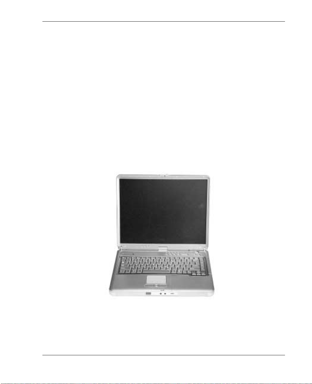
About Your NEC Versa L320 Notebook
The NEC Versa L320 notebook computer offers you a por table system filled with
exciting resources for business users. Standard features include a powerful Mobile
®
Pentium® III Processor-M running at 933 MHz, 1 GHz, 1.13 GHz, or higher.
Intel
This processor is designed to work together with the latest Peripheral Component
Interconnect (PCI) architecture.
Your notebook computer supports up to 1 GB of system memory. In addition, your
system come s with a high-performance hard disk drive, diskette drive, PC Card support
and one of the following variable-speed opti ca l dri ves: CD- ROM, DVD- ROM,
CD-RW, or combination CD-RW and DVD-ROM. Mi crosoft
Edition (SE) or Windows 2000 Professional is preinstalled. To optim i ze your
connectivity options, all systems ship with a built-in MDC modem and some models
come wit h a M in i PCI LAN or Mini P C I wireless LAN ( when available). A s a
multimedia system, your NEC Versa L320 supports the AGP x4 stan dard and provides
the tool s needed to create an d present impressi ve i mages using video clips and s ound.
NEC Versa L3 20 no tebook computer
®
Windows® 98 Second
To get comfortable with your notebook, read the followin g sections and take a tour
around you r syst e m!
Introducing the NEC Versa 1-3
Page 14
Around the Front of the System
The NE C Ver s a is compa ct with features on every side. First, look at the front of the
system.
Opening Your System
Open your NEC Versa L320 notebook computer by sliding the LCD pan el latch to the
righ t. Lift the cover to reveal the LCD panel and the ba s e unit feat ures. See the section,
“Front Featur es,” to locate the latch.
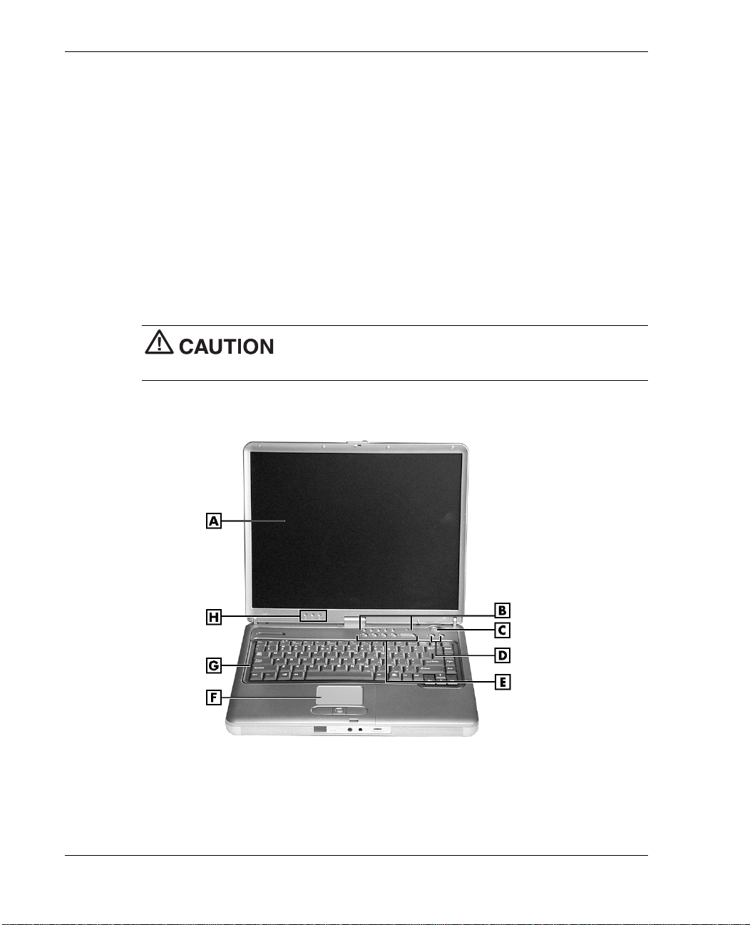
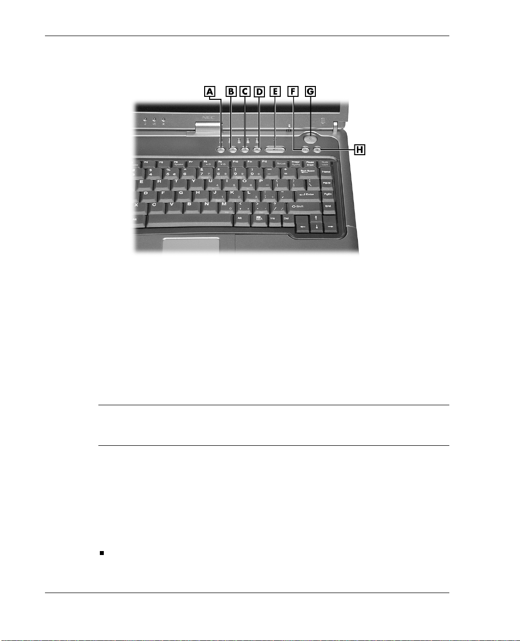
Base Unit
The base unit of your NEC Versa notebook offers the featur e s shown in th e follo wing
figure. Feature descriptions are provided after the figure.
After extended use, the surface of the base unit, below the
keyboard, may become hot to the touch.
LCD pa nel and ba se unit
A
– LCD Panel
B
– Operating Status LEDs
C
– Power Button
D
– Shortcut Buttons
1-4 Introducing the NEC Versa
E
– Personal Code Buttons
F
– NEC Ver s aGlide Touchpad
G
– Keyboard
H
– Power Status LEDs
Page 15

LCD Pan el — Provid e s a high-r e s olut ion di s play for sha rp, e ffective vi suals on
your N EC Versa notebook .
Operating Sta tus LEDs — Keep you informed of your N EC Vers a noteb ook’s
curr en t op erating statu s (see the section, “Status LE Ds”).
Power Button — Powers on and off t he system ( see the section, “Control Panel”).
Shortcu t Buttons — Launch you r browser or your e-m a il app l ication with these
buttons (see the section, “Control Panel”).
Person al Code Buttons — Sets a person al code for securit y. Ava ilable on some
systems ( s ee the sect ion, “Control Panel”).
NEC VersaGlide™ Touchpad — Work s lik e a s tandard com p uter mouse. Simply
move your fingertip over the VersaGlide to control the position of th e cursor. Use
the selection buttons below the VersaGlide to select menu items. See “NEC
VersaGlide Touchpad” in Chapter 2 for in formation about using the VersaGlide and
for cus tomizing VersaG lide sett ings.
Keyboard — Pr ovides 87 keys with t he sta ndard QWE RTY-k e y l ayout. ( Model s
pur cha s ed ou tside of the U.S. and Canada ship with cou ntry-sp ecific keyboar d
layouts.)
Power Status LEDs — Indicate whether the system i s running on AC power or
battery power, and indica te battery statu s (s ee the secti on , “Status LEDs”).
Control Panel
The NEC Versa L320 control panel provides the features shown in the following
figure. The control panel featur es ar e d es cribed a ft er the figure.
Introducing the NEC Versa 1-5
Page 16
Control panel
A
– Personal Code Button 1
B
– Personal Code Button 2
C
– Personal Code Button 3
D
– Personal Code Button 4
Security and Personal Code Buttons
Some s ystems have Personal Code Settin g buttons. Use th e buttons to set, enter,
chang e, or cancel a personal security code. See “Personal Code Setting Utility” in
Chapter 4 for more information .
Power Button
Note
Power button and hold it in place approximately 4 to 5 seconds until the system powers
off.
The Power button is a “smart” switch . It recognizes when th e s ystem is in a
Windows 98 or Windows 2000 Standby m ode, if the BIOS paramet er “Power Switch”
is set to “Sleep.” If the system is in Standby mode, you cannot power off until you
press the Power button to resume operation.
Put the unit in Standby mode when you need to be away from your system for a short
period of time and want to return to where you left off. Standby mode shuts down all
devices in the s ystem whil e r etainin g data and system status.
If you are unable to power off the system, use the power over ride. Press the
In Windows 98 and Windows 2000, go to Start, Shutdown, Standby to put your
system into Standby mode.
E
– Personal Code Enter Button
F
– Shortcut Button
G
– Power Button
H
– Shortcut Button
1-6 Introducing the NEC Versa
Page 17
Use the Power button in the following ways:
— Press th e Power button to power on.
— Press the Power button to resume from a Windows 98 or Windows 2000
— Hold th e Power button in place for 4 or more seconds to initiate power over r ide
Shortcut Buttons
Some systems h a ve shortcut buttons tha t you can configure to launch your default
Internet br ows er and your defa ult e-mail appl ication. See “One- Touch Star t Bu tton
Settings Utility” in Chapter 4 for information about configuring the buttons.
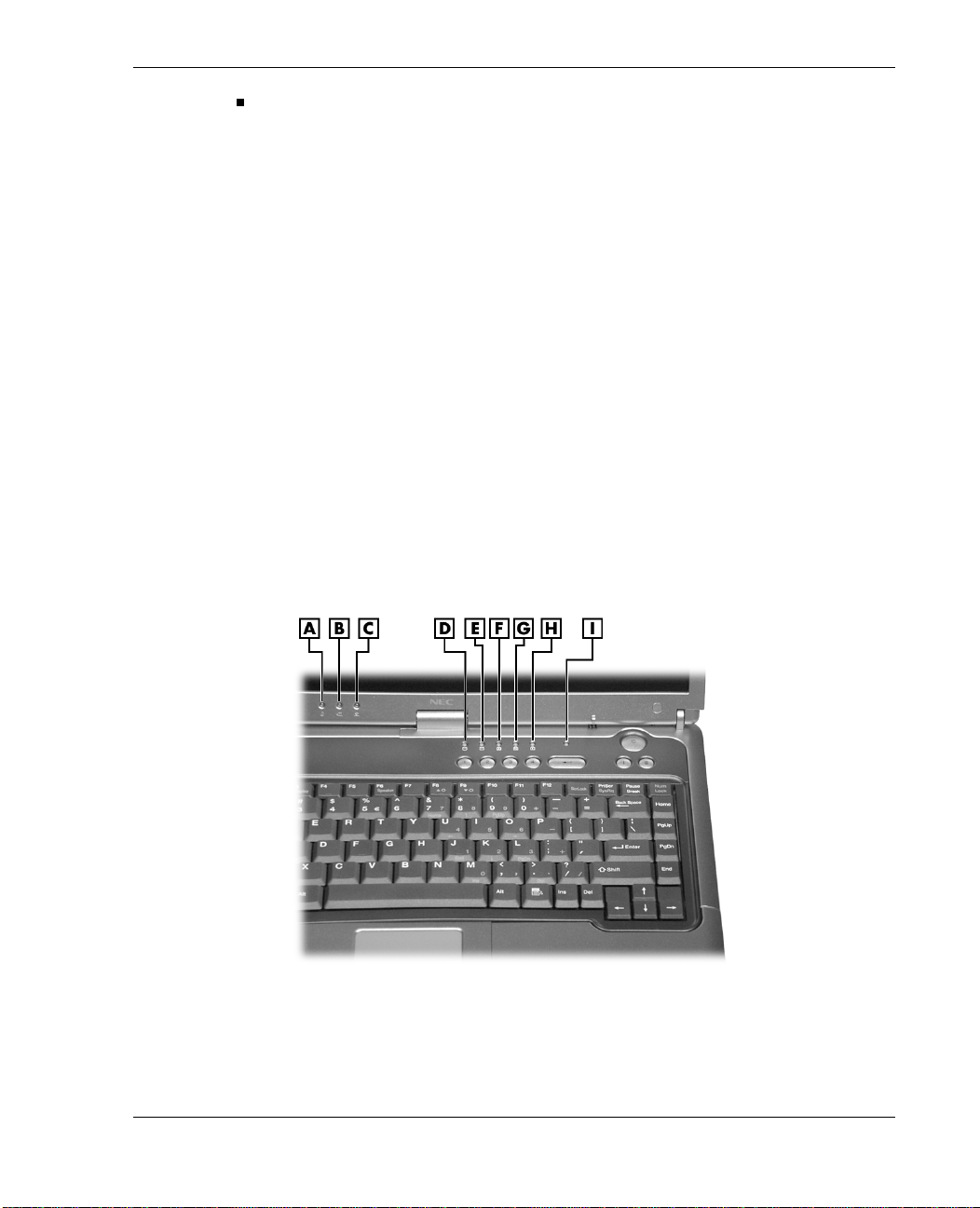
Status LEDs
The NEC Versa L320 system uses status lights marked with icons to comm uni cate
power status an d operating statu s. M ost of these LED s are on th e con trol panel (see the
following figure). See the following sections for information about each LED.
Standby mode an d proceed with normal operation.
(po wers of f the s ystem) . Only use this option if you cannot p ower off your
system using Start, Shutdown.
Control panel LEDs
A
– Power LED
B
– Battery Status LE D
C
– E-mail Notifi cation LED
D
– Drive Activity L ED
E
– NEC Modular Bay Drive Activity LED
F
– Caps Lock LED
G
– Scroll Lock LED
H
– Num Lock LED
I
– Security Indicator LED
Introducing the NEC Versa 1-7
Page 18

Note
of t he uni t. See “Around the Right Side of the System” to locate the LED and for a
description of the LED.
The Radio Wave Status LED (available on some models) is on the right side
Power Status LEDs
Power Status LEDs in d icate your NE C V er s a L3 2 0 ’s current power status.
Power Status LED — Lights to indicate the following status:
— Light s green when the system po wer is on.
— Blinks green when the system is in Standby mode.
— Lights yel l ow (blinks when in Standby mode) to indicate that bat tery power is at
8% capacity or less.
— Light s amber (blinks when in S tandby mode) to indicate that batter y power is at
3% capacity or less.
Battery Charging LED — Lights to indicate battery charging activity.
— Light s amber when the primary battery is charging. Blinks amber to in d icate an
error. The primary battery is installed in the battery bay.
— Light s green when the secondary battery is charging. Blinks green to indicat e an
error. The secon d ary (optional) battery is hou s ed in the NEC Modu lar Bay.
Note
back of the LCD panel. You can see t hese LEDs when you are behind your notebook
computer or when the LCD panel is closed.
The system al so has a Power Status LED and a Battery Charging LED on the
Operating Status LEDs
Operating sta tus LEDs keep you inform ed of your NEC V er s a L3 2 0’s curren t op erating
status.
E-mail Notification LED — Some systems have an LED that lights when new
e-mail is received.
Note
You can see t his LED when you are behind your notebook computer or when the LCD
panel is closed.
1-8 Introducing the NEC Versa
The system al so has an E-mail Notification LED on the back of the LCD panel.
Page 19
Drive Activity LED — Li ghts when th e NE C Versa L320 a cces s es the hard disk or
an NEC VersaBay™ IV drive (second hard disk, CD- ROM, DVD- ROM, CD-RW,
or combination CD- RW and DVD-ROM drive).
NEC Modular Bay Drive Activity LED — Lights when the NEC Ve rsa L32 0 writes
data to or retrieves data from the diskette drive in the NEC Modular Bay.
Caps Lock LED — Lights wh en caps lock is in ef fe ct.
Scroll Lock LED — Lights when scroll lock is in effect (not supported in the U.S.
or Canada).
Num Lock LED — Lights when num lock mode is active.
Security Indi cator LED — Ligh ts green when the system is in security mode (not
supported on all systems).
Radio Wave L ED (on the righ t side of the system) — Ligh ts gree n when a
Bluetooth™ (when avail able) or Wireless LAN d evice is on. The LED goes out
when th e device is in a S leep mode. To locate th is LED, see the figure “Right-side
features” later in this chapter.
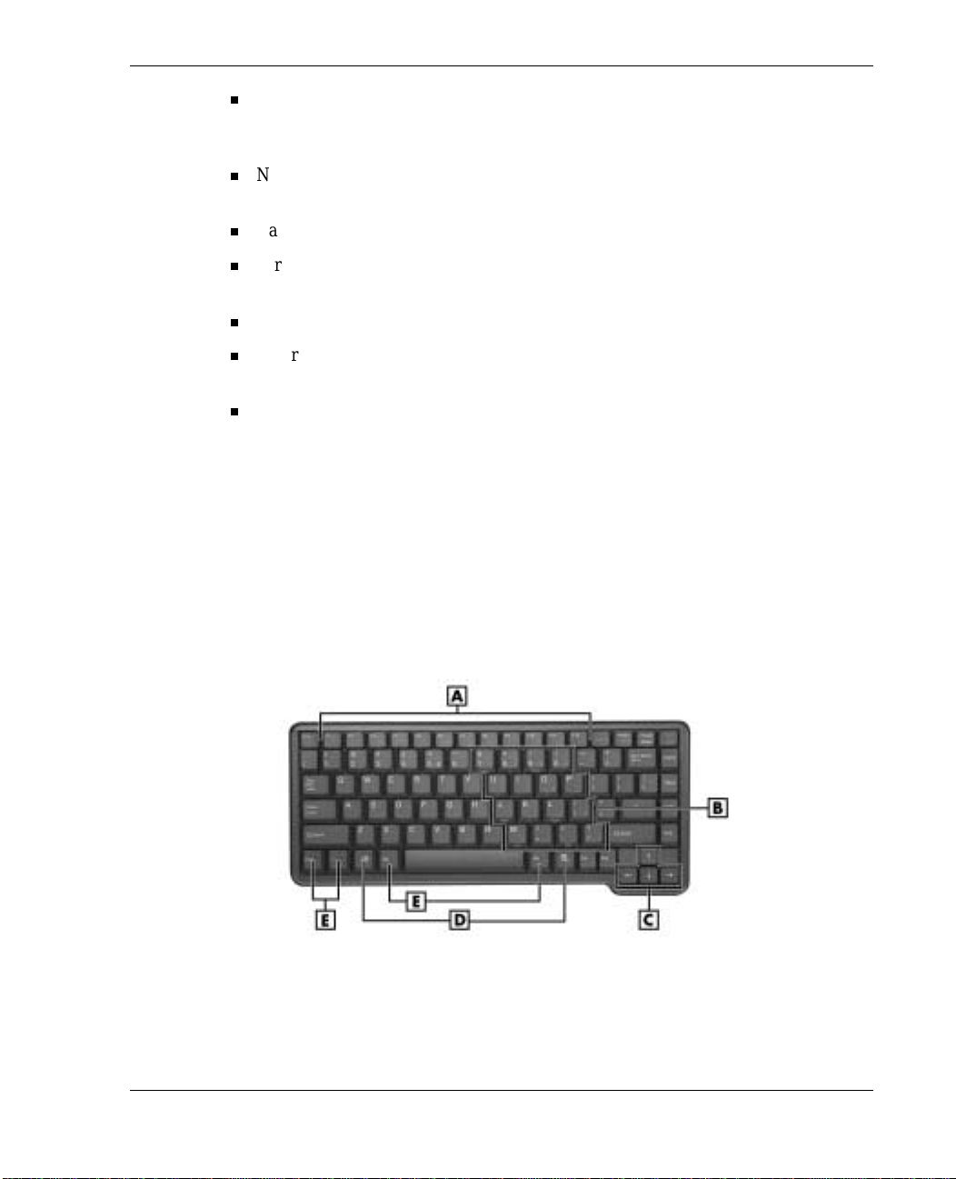
Keyboard Panel
The NEC Versa L320 keyboar d has a standard QWERT Y-key layout. (Model s shipped
outs ide the U.S . are equipped wi th countr y-s pecific k eyboa rd layout s.) Keyboa rd
features are described after the figure.
A
– Function Keys
B
– Numeric Keypad
C
– Cursor Control Keys
Keyboard
D
– Windows Keys
E
– Control Keys
Introducing the NEC Versa 1-9
Page 20

Function Keys — Twelve function keys, F1 through
Versa L320 keyboar d. These keys wor k together with the
F12
, are avail able on th e NEC
Fn
key to act ivate special
preprogrammed functions.
Function keys can also be used within applications. Most are application-driven, so
their functi on varies accor d ing to th e ap pl ication in u s e. See the speci fi c
application’s user guide for in formation about how each function key works within
the application you are using.
The following function key combinations are pre-programmed for the NEC Versa
L320.
Fn-Left Ctrl
— Simulates pressing the ri ght control key to support IBM 327X
connections (not supported in U.S./Canada).
Fn-F2
Fn-F3
Toggles a wireless device on and off (supported in some systems).
—
Toggles the video mode between LCD only, CRT only, Simultaneous
—
mode, and TV out.
Fn-F4
— Support ed for Wind ows NT® Workstation 4.0. Sets standby power
management mode on in Windows NT.
— In Windows NT, press any key to resume from Stand by mode.
— No function wh en Windows 98 or Windows 2000 is configured for Advanced
Configuration and Power Interface (ACPI). In Windows 98 or Windows 2000,
Standby is equiva l ent to the Windows NT Suspend mode. To resume from the
Windows 98 or Windows 2000 Standby mode, press the Power button.
Fn-F5
— Zooms the s creen in or ou t slight ly.
Fn-F6
Fn-F7
Toggl es the system speakers/beep of f and on.
—
— Toggles between various power management levels in Windows NT.
Beeps in dicat e the level chosen as follo ws:
1 beep Off
2 beeps Custom
3 beeps Highest Performance
4 beeps Longest Life
Fn-F7 has no fun ction when Windows 98 or Windows 2000 is con figured for
Advan ced Configuration and Power Interface (ACPI).
Fn-F8
— Increases LCD brightness (ei ght settings).
Fn-F9
— Reduces LCD br ightness (eight settings).
Scroll Lock
— Toggles th e s cr ol l lock featu re on and off.
1-10 Introducing the NEC Versa
Page 21

Windows Keys — Use the following two keys to facilitate your work.
Shortcut/Application key – provides quick access to shortcut menus.
(This key acts like a right mouse button.)
Floating Window key – disp lays the Start menu.
Numeric Keypad — Pressing
Num Lock
on the keyb oa rd activates th e numeric
keypad numbers and func tion s print e d in yellow on top of t he ke ys.
The keypad lets you type numbers and mathematical oper ands (+, –) as you would
on a calculator. The keypad is ideal for entering long lists of numbers.
When you press
Num Lock
again, the keys revert to their normal functions as
typew riter keys.
Typewr iter Keys — Typewriter keys (also called alphanumeric keys) are used to
enter text and ch aracters. Keys with yellow print on them behave differently when
combined with control keys, the
Control Keys —
Ctrl, Alt, Fn
Fn
, and
key, or wh en
Shift
are controls used in con junction with oth er
Num Lock
is active.
keys to ch ange th eir functi ons. To use con trol keys, p ress and hold the con trol key
Ctrl C
whil e pressing another ke y. For exampl e, “Press
Ctrl
key and type the letter C. Key combinations work specific to the application
” means to ho ld do wn the
you are running.
Cursor Control Keys — Cursor control keys let you position the cursor on the
screen where you want. On the screen, th e cursor is a blinkin g und erline, block, or
verti cal bar dep ending on the appli cation. The cursor in d icates where the nex t text
typed is inserted.
Introducing the NEC Versa 1-11
Page 22

Front Featur es
The features on th e front edge of the system are described aft er the figure.
Front features
A
– LCD Panel Latch
B
– Speakers
C
– IR Por t
D
– Built-In Microphone
LCD Pan el Latch — Slid e the latch to the right to open the N EC Versa L320
E
– Microphone In Port
F
– Headphone In Port
G
– Volume Control
system.
Ster eo Sp eakers — Provide stereo sound for your m ultimedia presentations or
listening pleasure. The built-in sound system also supports 3D sound, which
simulates the latest surround-sound technology.
IR Port — Allows you to tran s fer files bet w een your N EC Versa and an in frared
(IR)-equipped deskt op or notebook comput er.
Microphone — Allows you to record monophonic sound directly into your
notebook com put er. See Chapter 9, “Using Multimedia,” for details about
recording.
Microph one In P ort— All ows you to conn ect an extern al microphone for
monophonic recording or amplification through the unit. Plugging in an external
microph one disables the built-in microphone.
Headphone In Por t — Lets you plug in stereo headphones or powered spea kers.
Volume Control — Allows you to cont rol the sp eaker volum e th rough th e thumb
wheel.
1-12 Introducing the NEC Versa
Page 23
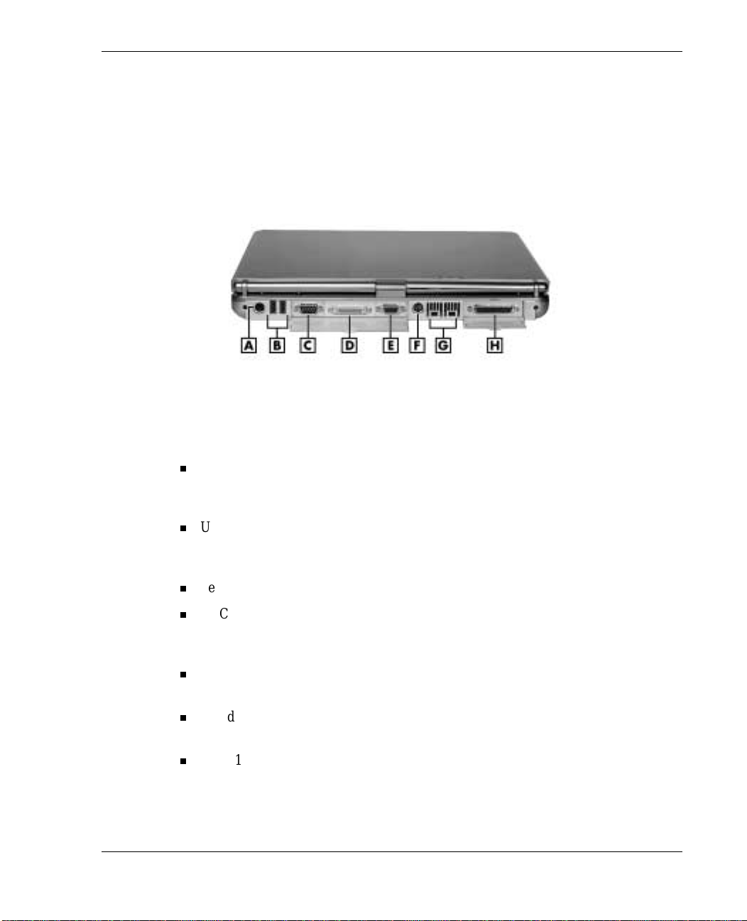
Around the Back of the System
You’ll find syst em ports for connecting your NEC Versa L320 to optiona l devices (like
a print er or ext e rnal m onit or) on the ba c k of your NEC Versa L320. The por ts are
described after the figure.
Back featur es
A
– PS/2 Port
B
– USB Ports
C
– Serial Port
D
– NEC Cable PortBar Connector
PS/2® Port — Use the standard PS/2 port to conn ect an exter nal PS/2- s tyle mouse,
E
– VGA P ort
F
– S-Video Out
G
– IEEE 1394 Po rts
H
– Parallel Port
PS/2- style keyboard, or P S /2 - s tyle Numeric Keypad to the system. With an optional
Y-adapter cabl e, you can connect up to two of t hese devices at th e s ame time.
USB P o rts — Each Universal Serial Bus (USB) port allows you to connect up to
127 USB-equipped peripheral devices (for example, printers, monitors, and
scanners) to your NEC Versa L320.
Serial Port — Use th i s por t to conn ect a digital camera or oth er serial d evice.
NEC Cable P ortBa r™ Conn ect or — Plug your optiona l NEC Cable P ort Bar (port
replicator) in to this connector. You can connect man y of your peri pheral devices to
the NE C Cable Port Bar instead of to the connectors on the back of the system.
VGA Port — Use this 15-pin port to attach an external monitor to your NEC Versa
L320.
S-Video Out Port — Use thi s p ort to connect a camcorder, VCR, or a game
machine for a conn ection th at provides i ncreas ed clarit y an d sh arpness of imagery.
IEEE 1394 Ports — Use each port to daisy chain up to 63 IEEE 1394 devices to
your system . IEEE 1394 devices suppor t Plug and Play connectivity for tr ansfer
rates of up to 400 Mbps. The Windows NT operating system does not support the
IEEE 1394 ports.
Introducing the NEC Versa 1-13
Page 24
Parallel Port — Connects a parallel printer or other parallel device. The parallel port
default supports the Enhanced Capabilities Port (ECP) standa rd. The port also
supports bi-direct i onal and output only pr otocols.
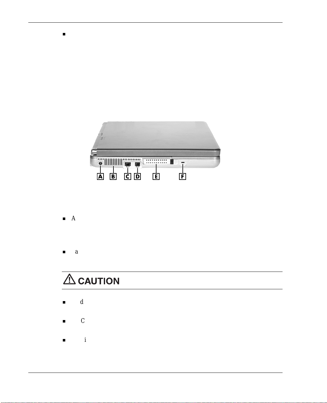
Around the Left Side of the System
The left side of your NEC Versa L320 provides the features shown in the following
figure. The left- s ide featu res are des cr ibed after the figure.
Left-side features
A
– AC Power Port
B
– Fan
C
– LAN Port
AC Power Port — Lets you attach the NEC Versa L320 to the AC power source
D
– Modem Port
E
– PC Card Slots
F
– Kensington Lock Slot
using the AC adapter that comes wi th your system. K eep the system connect ed to
AC power whenever p oss ible to keep the battery pack and intern al CMOS battery
charged.
Fan — All ows your syst em to cool properly and maintai n a safe opera tin g
environment.
Do not block t he fan while the NEC Versa L320 is in use.
Modem/LAN Ports — Some system s include a V.90 fax/data modem or a Mini PCI
LAN port for network or Intern et access.
PC Card Slots — Two PC Card slots all ow you to i nser t two T ype II PC Ca rds or
one Type III PC Card in the bottom slot.
Kensington® Lock Slot— This slot allows you to attach a Kensington security lock
or oth er compatible lock to secure the notebook from theft.
1-14 Introducing the NEC Versa
Page 25
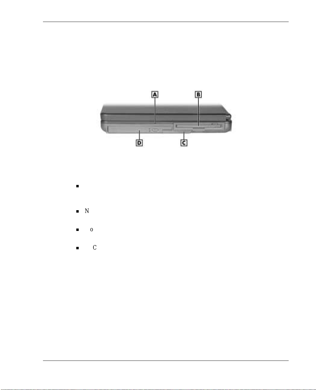
Around the Right Side of the System
The righ t side of t he NEC Vers a L320 offer s t he fea tur es shown in the following figure.
The right side features are described after the figure.
Right side features
A
– Radio Wav e Stat us LED
B
– NEC Modular Bay Slot
Radio Wave S tatus LED — Provid e s th e opera t i ng st a tus of a Blue tooth ™ or
C
– Modular Bay Latch
D
– NEC VersaBay I V Slot
Wireless LAN devi ce. The LE D li ghts green when the Blu etooth or Wireless LA N
device i s on . The LED goes out when the d evice is in a Sleep mode.
NEC Modular Bay Slot — Houses a diskett e dr ive or an opti onal secondary battery.
Devices ca n be swapped wit hout t he syst e m being disas s e mbled or tur ned ove r.
Modular Bay Latch — Slide th e latch to the left before removing a Modular Bay
device fr om th e s ystem.
NEC VersaBay IV Slot — Houses a CD-ROM, CD-RW, DVD-ROM, combin a t ion
CD-RW and DVD-ROM drive, or a second har d dri ve. On e of these dri ves comes
with th e notebook. This slot accommodates an optional hard disk drive that has
been pl aced in a specially desig ned cradle.
Introducing the NEC Versa 1-15
Page 26
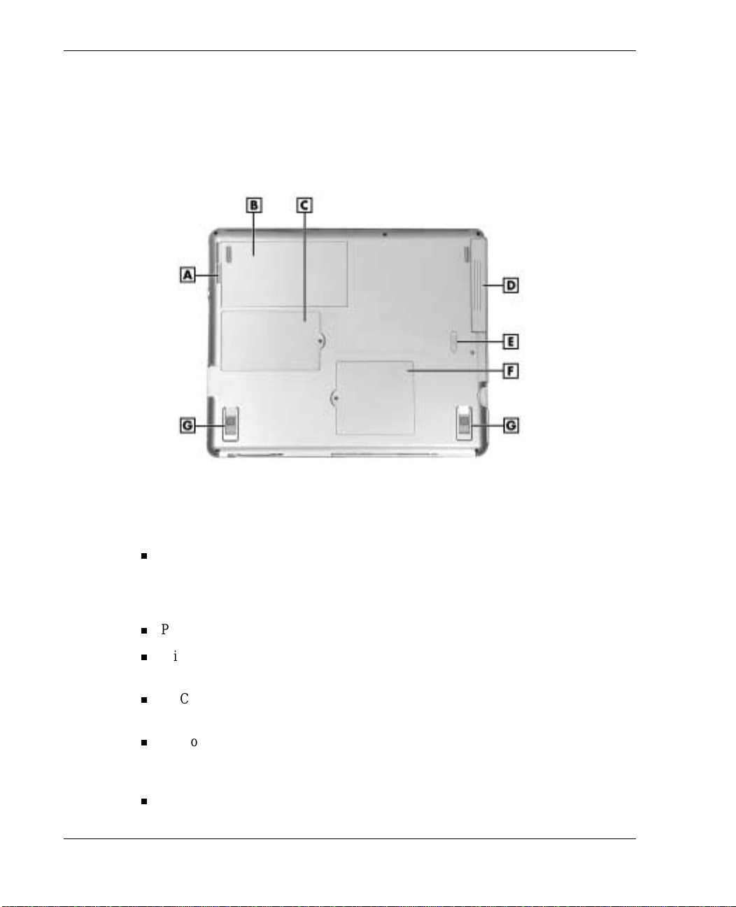
Around the Bottom of the System
The bottom of the NEC Versa L320 offers the features shown in the following figure.
The features are descri bed after the figur e.
Bottom features
A
– Battery Rel ease Latch
B
– Primary Battery Bay
C
– Mini PCI and MDC Bay Cover
D
– NEC VersaBay I V Slot
Battery Release Latch — Press th e latch toward the edg e of t he system and hold it.
Lift the battery up slightly by its edge and pull the battery toward the edge of the
system to free the battery connectors and remove the battery. Do not lift the battery
straight up.
Pri mar y Ba ttery Bay — Equipped with a lithium ion (Li-Ion) battery.
Mini PCI and MDC Bay Cover — Remove the screw to find the Mini PCI or MDC
card.
NEC VersaBay IV Slot — Houses a CD-ROM, CD-RW, DVD-ROM, combin a t ion
CD-RW and DVD-ROM drive, or a second har d disk drive.
Memory Module Bay Cover — Remove the screw to find two SO-DIMM slots.
One sl ot contain s an SDRAM memory board configured by the factory. The oth er
slot is empty for upgrade use.
Til t Foot — Ad j ust each foot to provide a flexi ble keyboard angle.
1-16 Introducing the NEC Versa
E
– VersaBay IV Latch
F
– Memory Module Bay Cover
G
– Tilt Foot
Page 27
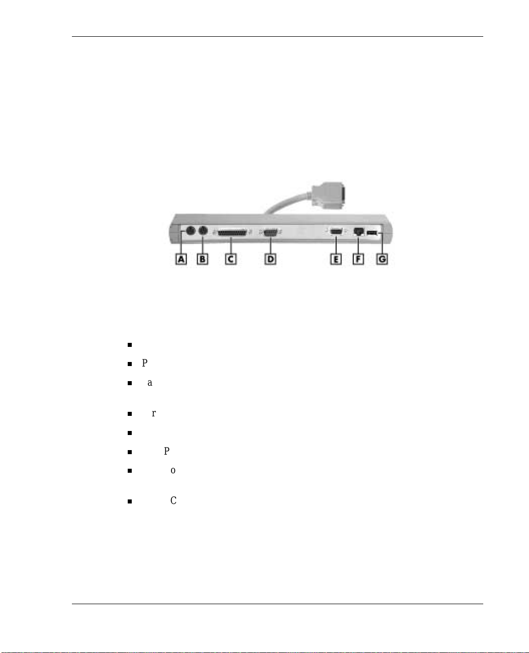
About the NEC Cable PortBar
The NE C Cabl e P ortBar is an a cces sory th at duplicates some of the port s on th e ba ck of
your NE C V er s a L3 2 0 system, including a power connector. Ports include a LAN port
for a network connection. Keep the NEC Ca bl e PortBar in your office c onnected to
peripherals while you take your NEC Versa L320 on the road.
The ports on the NE C Ca bl e PortBar are descri bed after the following figur e.
NEC Cable PortBar
A
– PS/2 Keyboard Port
B
– PS/2 Mouse Port
C
– Parallel Port
D
– Serial Port
PS/2 Keyboard Port — Connects to a 6-pin standard PS/2-style ke yboard.
PS/2 Mouse Port — Connects to a PS/2-style mou se.
Parallel Port — Conn ects to a print er . You can change the LPT M ode in the Set u p
E
– VGA P ort
F
– LAN Port
G
– USB Port
program.
Serial Port — Conn ects to a serial device, such as a digital camera.
VGA Port — Connects to an external VGA/SVGA monit or.
USB P o rt — Connects up t o 127 peripheral devices to your notebook c omputer.
LAN Port — Connects vi a an RJ-45 connector t o th e s yst em’s built-in LAN card
(available on some models).
Power C onnector — Conn ects to an AC a da pt er . The NEC Ca bl e PortBar has two
power connect ors on the left s ide of the P or tBar (see the following figure). Use the
19-volt DC power connector for the NEC Versa L320 n otebook computer.
Introducing the NEC Versa 1-17
Page 28
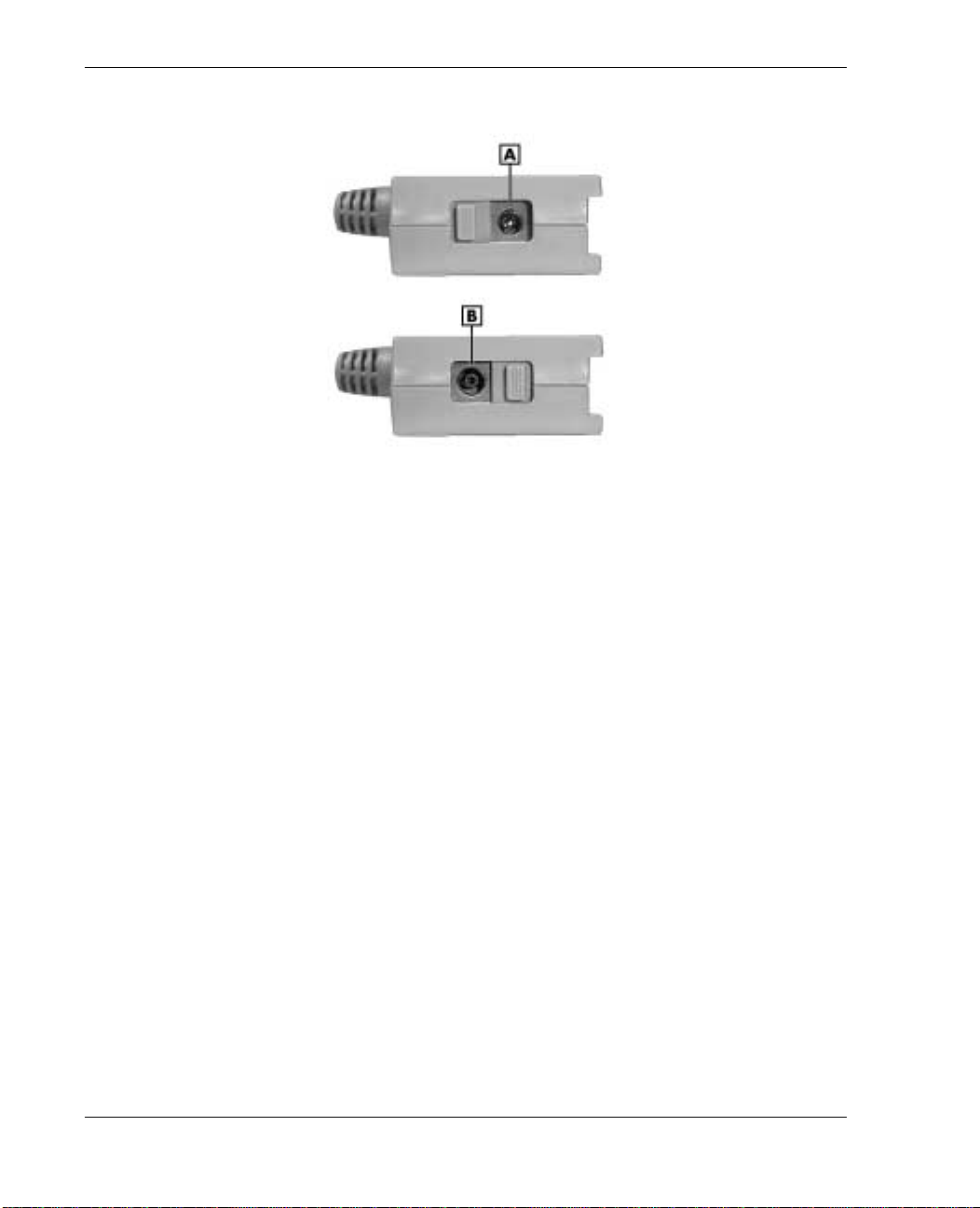
NEC Cable PortBar power connectors
A
– 19-volt DC Power Connector for the NEC Versa L320 system
B
– 15-volt DC Power Connector (for future use)
About NEC Wireless LAN
Some NEC Versa L320 notebook computers come with built-in wireless LAN
capabilities featur ing the Wi-Fi™ (wireless fidelity) IEEE 802.11b High Rate (HR)
stan dard for bus iness users. Wirel es s LA N eliminates the n eed for conn ecting cables
between your computer and your local area networ k, facilitating mobility, minimizin g
downtime, and improving your product ivity. With a wir eless L A N solution, you have
the flexibility of accessin g e-mail, th e In ternet, corporat e intranets, and res ource
planning application s on the network from your notebook computer.
The Wi-Fi compliant radio techn ology provides high- s p eed (11 Mbps) wireless
networ king with the perfor mance ca pa biliti es of a wi red 10BaseT LAN conn ection.
Wi-Fi products are tested by an industr y group, WEC A (Wireless E thernet
Compatibility Alliance), to meet the international IEEE 802.11b standard for wireless
radio technology an d guaranteed to wor k with all other Wi-Fi certified pr oducts.
1-18 Introducing the NEC Versa
Page 29

Getting Started
NEC VersaGlide Touchpad
Power Sources for Your NEC Versa
AC Adapter
System Batteries
Using the Primar y Batt er y
Using a Secondary Battery
System Care
2
Page 30
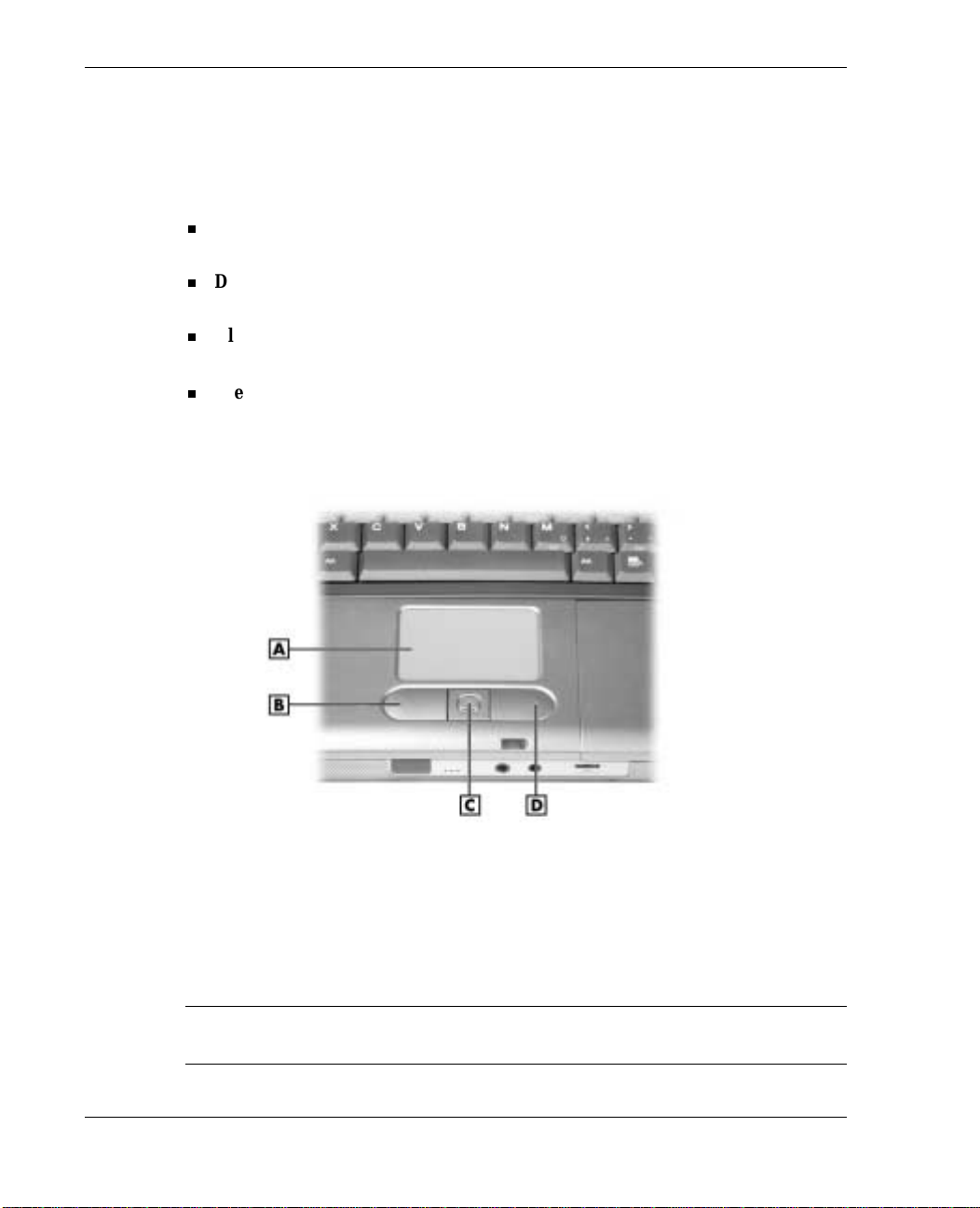
NEC VersaGlide Touchpad
The NEC VersaGlide touchpad is an easy way to control the cursor with your finger .
Lightly glid e your finger a cross the NEC VersaGlide and th e cursor follows. Use the
VersaGlide touchpad as follows.
Single tap the touchpad
— equivalent to a single click of the primary mouse
button.
Double tap the touchpad
— equivalent to a double click of the primary mouse
button.
Click
and
hold,
then
your finger acr oss the VersaGlide touchpa d —
drag
equivalent to a click and drag of th e primary mouse button.
the scroll button up or down to scroll your document or screen.
Press
VersaGlide features
A
– NEC Ver saGlide touchpad
B
– Left Button
Try all of the VersaGlide fea tures and decide wh ich you prefer. If you find the doubl e
tap or any of the other features difficult to use, go to the n ext section for general
direct ions about adjust in g the Versa G lide properties.
Note
capability may be lost.
2-2 Getting Started
C
– Scroll Button
D
– Right Button
If you install another m ouse driver ov er the s hipping default, t he double- tap
Page 31

VersaGlide Adjustments
The NEC VersaG l ide of fers a numbe r of option s t hat l e t you customize h ow it
function s. The options let you control the cursor speed, select button orientation, enable
or disable tapping, define auto jumps, enable easy-scr olling, and configure gestures t o
initiate selected functions by tapping in a designated area of the touchpad.
To access these options, locate the Windows Control Panel and double click the mouse
icon. Use the con t ext-sen sitive help to learn m ore about each option. S elect th e option,
F1
and then press
to access the context sensitive help.
VersaGlide Tips
Follow t hese basi c tips while workin g :
Use a light touch on the Ver saGlide surface.
Set up the NEC Versa notebook with your keyboa rd and VersaGlide at a
comfortable h eight. Keep your forearms parallel to the floor. Your wrists should be
relaxed and straight.
While u s in g the keyboard and VersaGlide, keep your should er s an d ar ms as relax ed
as possible.
Take regular breaks from the computer to rest your eyes. Perform stretching
exercises to relax your fingers, hands, wri sts, forearms, and shoulder s.
See Appendix A, “Setting Up a Healthy Work Environment,” for more information.
Power Sources for Your NE C Versa
The NEC Versa notebook can be powered using three different sources, making it a
truly portable system.
Operate your N EC Vers a j ust about anywhe re us i ng one of the following power
sources:
the AC ada pter connected to an electrical wall outlet (using AC power)
battery power :
— the 8- cell primary battery
— with or wi thout th e optional 8-cell secon d ary battery that install s in the Modular
Bay slot.
the optional auto adapter. (Not available for all location s. For availability, consult
your NEC Computers vendor. For details about usin g an auto adapter, refer to the
accessory sheet that ships with th e op t ion.)
Getting Started 2-3
Page 32

Read the followin g sections for specific information about using the NEC power
sources.
AC Adapter
Use th e AC adapter an d p ower cable th at came with your NEC Ver s a n ot ebo ok to run
your computer on alternating curren t (AC) power or to recharg e the batter y.
Keep the adapter connect ed whenever p oss ible. The AC adapter charg es th e ba ttery
when it is connected , wheth er the NEC Vers a n ot ebook is p ower ed on or off.
AC adapter
A
– AC Adapter
B
– AC Adapter Cable
adapter has no user-replaceable or serviceable parts inside. Dangerous voltage in the
AC adapter can cause serious personal injury or death. The AC adapter is intended for
use with a com puter and must meet EN609050 standards.
Connecting the AC Adapter
Note
wher e you are u sing it. Contac t the local d ealer to pu rcha se th e correct power cable.
Connect the AC adap ter as follo ws.
1.
2-4 Getting Started
The AC pow er ca ble type th at your system uses depends on the count r y
Connect the AC adap ter cabl e t o the power p ort on the left side of your NEC V er s a
notebook.
C
– Power Cable
Do not attempt to disassemble the AC adapter. The AC
Page 33

2.
Plug on e end of the AC power cable into the AC adapter and the other en d in to a
properly grounded 120- or 240-volt, 50- or 60-Hz wall outlet.
Connecting the AC adapter
Do not cover or place object s on the AC adapter . Keeping the
adapter clear of obj ects lets the adapter cool properly during use.
Only use the AC adapter that comes with your NEC Versa L320. Although other
adapters look similar, using them can damage your syst em.
Powering On Your System
Power on the system as follows.
1.
Locate the lat ch on the front of t he LCD pan el, s lide it to th e r ight, and raise the
panel.
2.
Locate the Power button and press it to turn on system power. For additional
information about Power control buttons and power LEDs, refer to Chapter 1,
“Introducin g the NEC Versa .”
Getting Started 2-5
Page 34

System Batteries
Your NEC Versa notebook is equipped with a primary lithium ion battery that helps to
prevent data loss. In addition, you can in sert an optional secondar y lithium ion battery
in the NEC M odular Bay sl ot to g ive you mor e on-the-g o power.
Primary Battery
The standard lith i um ion (Li-Ion) battery provides the main power source in your NEC
Versa L320 computer. Your system comes with an 8-cell lithium ion battery that fits
into the ba ttery bay on the bottom of your system. Se e A ppendix B for ba tter y
specifications. In addition to this battery, the CMOS battery also provides system
power.
For information about installing or removing the primary battery, see the section,
“Replacing the Battery ” later in this chapter. For more information about the primary
battery see the section, “Using the Primary Battery.”
Secondary Battery
You can install an optional secondary lithium ion battery in the NEC Modular Bay slot
on the ri ght side of your NEC Vers a noteb ook. Attachin g a second fully charge d bat tery
allows you to work longer while you are awa y from an AC power source. For more
information about th e secon dary bat tery, see the secti on, “Using the Second ary
Battery.” For infor mation about installing a secondary battery, see “Instal ling a Device
in the Mod u lar Bay Slot” in Chapter 5 or s ee the installation instru ctions that are
packaged with the battery.
CMOS Battery
This lithium ba t tery provides battery backup and prevents data loss in the system’s
complementary metal oxide semiconductor (CMOS) RAM. This memory area contains
information on the system’s configuration, for example, date, time, drives, and
memor y. The CMOS bat tery char ges when your N EC Versa n ot ebo ok is connected to
AC power. The CMOS battery may discharge completely if the NEC Versa notebook
remain s unus ed for a pprox i mately two m onths.
2-6 Getting Started
Page 35

Using the Primary Battery
The NEC Versa notebook comes with a rechargeable 8-cell lithium ion (Li-Ion) battery
that’s easy to inst all and rem ove.
Primary battery
A
– Primary Battery
B
– Battery Latch (hidden)
the following:
Keep the b attery away from extrem e heat.
Keep metal objects away from the battery connectors t o prevent a short circuit.
Make sure the batt ery is properly installed in the battery bay.
Read the precautions printed on t he battery.
Determining Battery Status
Your NEC Versa system provides tools to help you keep track of the main (and an
optional) battery’s power level. If your syst em is configured (default setting) to display
the Power icon on the taskbar, an electrical pl u g ap p ears when th e s ystem is connected
to an AC p ower sou rce or a battery icon ap p ears when the system is n ot connected to an
AC power source.
C
– Conn ecto r
To prevent accidental battery ignition or explosion, adhere to
Getting Started 2-7
Page 36

Use th e s ystem’s power meter to determine battery status. Access the system’s power
meter in the following ways:
Move the c ursor over the Power i con on the taskbar to di s play the remaining batter y
power for the system ’s primary battery.
Right click the Power icon on the taskbar to open the power meter or to adjust
power properties.
Double click the Power icon on the taskbar to dis p lay the remaining p ower for both
the primary and optional secondary battery (if installed).
Go to Start, Settings, Control Panel, and double cl i ck the Power Management i con.
Select t he Power Meter tab.
Low Battery Status
When battery power is low (8% or less), the power LED lights yellow (blinks in
Standby mode). When battery power is very low (3% or less), the power LED lights
amber (blinks in Standby mode). When your system is in a low battery status, do one of
the following:
Power off the system, remove the spent battery, an d replace it with a fully charg ed
battery.
Leave the spent batter y in th e s ystem and con nect your NEC Versa n ot ebo ok to the
AC adapter and a wall outlet.
Returning the Battery to its Normal State
To return the batt ery to its normal state, try the followin g :
Remove and then reinstall the battery.
Reinstall the battery in your NEC Versa notebook and fully recharge the batter y (to
100%).
Refresh the batter y using the Refresh Batter y function in the Exit menu of the BIOS
Setup utility (see “Exit Menu” in Chapter 3).
Extending Battery Life
While on the road, it is important to be aware of the simple things you can do to extend
the life o f t he system’s main battery. One way is to keep the brightness setting low. Use
Fn-F8
the
In addition, NE C C om p uters recommends that you always opera te your system on AC
power when using any external device and when playin g DVD movies.
2-8 Getting Started
and
Fn-F9
function keys to control the brightness.
Page 37

Battery Handling
Keep the following in mind when removing or replacing a battery.
Use only t he battery designed for your NEC Versa notebook. Mixing other
manufacturers’ batteri e s , or using a com bin ation of ve ry old an d new batteries c an
dete riorat e ba tter y a nd equipm ent performan ce .
Turn off po w er to the system after use. Keepin g s ystem power on can degra d e
battery performance and shorten battery life.
Clean the battery connect ors with a dr y cloth when th ey get dirt y.
Keep the battery out of the r each of chil dren.
Replacing the Batter y
The following symptoms indicate that battery life is nearing an end. Replace batteries
that display these symptoms.
Shorter work times.
Disc oloration, wa rping.
Hot to the touch.
Str a nge odor.
Replace t he batt ery installed in your N EC V er s a s yst em as foll ows .
Note
another manufacturer’s bat t ery or using a com bination of very old and new batteries can
deteriorate battery and equipment performance.
1.
2.
Only use batteries that are designed for your NEC Vers a computer. Installing
Save your files, exit Wind ows, and turn off system p ower.
Close the LCD panel and turn over the system .
Getting Started 2-9
Page 38

3.
Slide th e battery release latch toward the edge of the system and hold firmly.
Locating the battery bay release latch
A
– Battery Rel ease Latch
B
– Indentation
4.
Grasp th e edge of the batter y at the indentation in the system ca s e. Lift the battery
C
– Primary Battery
up slightly. Once the edge is free, pull the batter y out at an angle. Do not lift the
battery straight up.
Remo ving the battery
2-10 Getting Started
Page 39

5.
Insert the new battery as follows:
Locate the conn ector on the ed ge of the battery.
Locate the conn ector inside the batt ery bay.
Place the battery in the battery bay at an an gle so the connector s line up.
Lower the battery into the bay, making sure that the battery release latch
secures the battery in pla ce.
Inserting the battery
6.
Turn the system over.
Charging the Batt ery
Charge the primary battery and optional secondary (Modular Bay) battery by simply
connecting your NEC Versa L320 system to an AC power source. T o monitor the
charging acti vi ty, observe t he bat tery charging LED on the front of th e s ystem. Th e
battery charging LED lights as follows:
Lights amber when the prim ary batter y is charging.
Blin ks amber if th e pr imary batt ery encounters an error whil e ch arging.
Light s green when the secondary battery is char ging.
Blin ks green if the secondary batter y en counters an error while charg in g.
Getting Started 2-11
Page 40

Battery Precautions
To prevent accidental batter y ignition, rupture, or explosion, adhere to the followin g
precautions.
incorrectly rep laced. Repla ce onl y w ith the same or eq uivalent type recom mend ed
by the manufacturer. Discard used batteries according to the manufacturer’s
instructions.
To avoid personal injury and property damage, read these bat t ery precautions on
handling, charging, and disposing of Li-Ion batteries.
Keep the batter y away from heat sour ces including direct sunlight, open fires,
microwave ovens, and high-voltage containers. Temperatures over 140º F
(60ºC) may cause damage.
Do not drop or bump the battery.
Do not disassemble the battery.
Do not solder the battery.
Do not puncture the battery.
Do not use a batt ery that appears damaged or deformed, has any rust on its
cas ing, i s discolored, over heat s, or emits a f oul o dor.
Keep the battery dry and away fr om water.
Keep metal objects away fr om battery connectors. Metal objects in contact
with the connectors can cause a short circuit and dam age.
If the bat tery leaks:
If the bat tery leak s ont o skin o r clot hing, was h t he area immediately with
clean water. Batt ery fluid can cause a skin rash and damage f abri c.
If b attery fluid g ets into ey es, DO N O T rub ; r inse w ith clear water immedia tel y
and consult a doctor.
Tak e extra precaut ions to keep a leakin g battery away f r om fi re. There is a
danger of ignition or explosion.
There is a danger of explosion if the battery is
Precautions for Recharging the Battery
Adher e to the following preca u tions wh en r ech arging the primary or secondary battery.
Char g e th e battery for the specified charge time only.
During charging, keep the environ mental t emperature between 32°F and 104°F
(0°C to 40°C).
2-12 Getting Started
Page 41

Using a Secondary Battery
An optional secondary 8-cell battery is available for your NEC Versa notebook. This
battery installs in th e M odu lar Bay slot on the righ t s ide of your comp u ter.
Use th e s econdar y battery in addition to the primary battery to extend the amount of
time you can run your system on battery power.
Secondary Battery Precautions
Use th es e precauti ons when using the secon d ary battery in th e Mod u lar Bay slot.
Do not attempt to run th e system on secondar y battery power if the primary battery
is not insta lled.
The connectors in th e pr imary batt ery bay shoul d not be exposed. Con nector s can
cause a danger if th ey are accidentally touched or if they conn ect with a metal
object d u r ing system op erati on.
Always install the weight-saving module that sh ip s wi th your syst em in the
Modular Bay slot i f no Modular Bay device is instal led in the sl ot .
Do not run the system on secondary battery power without the
primary battery in place. The connectors in t he primary battery bay can cause a danger
if they are accident ally touched, or if they connect with a metal object.
If the Modular Bay slot is empty, always install the weight-saving m odule to prot ect the
bay and the connectors within it.
Also see the precaution s in the section, “Using the Primary Battery” for information
that ap plies to the safe use of the secondary battery.
Replacing the Secondary Battery
See “Removing a Devi ce from th e N EC M odular Bay Slot ” and “Installing a Device
in the NEC M od u lar Bay Slot” in Chapter 5 for instructions on installing or removing
the opt ional 8- cell secondary batt ery from the Modular Bay.
See th e previous sect ion, “Secondar y Battery Precauti ons” for information abo u t the
safe use of t he secondary batt ery. Also see the sect ion, “Using the Primary Battery”
earlier in this chapter for general information about handling s ystem batteries.
Getting Started 2-13
Page 42

System Care
The NEC Versa L320 notebook computer is designed t o be a durable, depen da ble
system built for extensive use and travel. Follow th ese guidelines to maintain the
condition and performance of your computer.
under the following conditions:
The power cord i s damaged or frayed.
Liquid spills on or int o the NEC Versa notebook.
The system is dropped or the casing is damaged.
Precautions for System Use
Follow these precautions when using your NEC Versa L320 computer and AC a dapter.
Avoi d dropping or bu m ping t he compute r or the AC ada pter .
Do not stack heavy objects on the compu ter, the AC a da p ter, or the batteries.
Avoi d movi ng the NEC Versa notebo ok during system operation, e s peciall y wh ile
the har d di s k , di s k ette drive, or other dr ive is being accessed.
When u s in g th e A C ad apter, make sure the power source falls within the system’s
compatible range of 100-240 volts and 50 or 60-Hz, AC. Never use the AC ada pter
if the voltage falls outside of this range. (Watch for this wh en traveling to other
countries.)
Turn computer power off before attaching or removing non-plug and play devi ces
that are not warm- or hot-swappable.
Do not push any for eign objects into the NEC Versa bays, conn ectors, and slots.
Do not set the computer on top of a ma gnetized area. Doing so can destr oy the data
on you r hard di s k drive. (Som e airline tray tables a re magnet ic.)
Avoid using the computer or AC adapter for extended periods in direct sunlight.
Do not use th e system in h umid or dusty environments.
Turn comp uter power of f b efore cl eaning it.
Avoid ex p osing th e NE C Versa notebo ok or AC adapter to extreme changes in
tem pera ture or humi dity. If it i s unavoida ble, a llow your NEC Ver sa not ebook to
adjust to room temperat ure before us e .
When cl eaning th e s ystem, use a soft , clean , dry cloth. Avoi d wi p ing the display
surface with abr a sive material, including rough fabric. Do not use a cleaning
solution; this may damage the notebook’s magnesium case.
If the AC adapter becomes extremely hot, unplug the adapter and let it cool.
Immediately turn off and unplug the NEC Versa notebook
2-14 Getting Started
Page 43

Storage Requirements
Store the compu ter and AC ada pt er in an environ ment that meets th e fol lowing
conditions:
or f alls ( for example, when you move the system from a cold place to a war m place)
vapor condenses i nside the system. Turning on the system under this condition can
damage the internal system c omponents .
Before turning on the system, wait until the system’s int ernal temperature equalizes wi t h
the new environment and any internal moisture evaporates.
Main tain storage temperatures bet w een -4°F and 104°F (-20°C and 40°C).
Keep the storage area free from vibra tion and ma gnetic fiel d s .
Keep the system an d its compon en ts away from organi c solvents or cor rosive ga ses .
Avoid l eaving th e s ystem and its componen ts in direct s unlight or n ear heat sources.
Routine Cleaning
Clean or dust your system as follows:
If the temperature of the NEC Versa notebook suddenly rises
Never use har s h solutions, household cleaners, or spray
cleaners that contain caustic mat erials on the NEC Versa computer.
These cleaner s ar e usually high in alkalinity, which is measured in pH. Using these
cleaners can harm the magnesiu m surface .
LCD scr een — Carefully wipe the LC D s cr een with a soft cloth or a scr een wipe
designed for that purp ose. Specia l s creen wipes are available through your local
comput er dealer .
System ca s e — NEC Computers recommends that you carefully wipe the case with
a sligh tly damp, almost dry cloth.
Getting Started 2-15
Page 44

Using the BIOS Setup Utility
Introducing BIOS Setup
Entering BIOS Setup
Checking/Setting System Parameters
Managing System Power
Checking Switch Settings
Updating the BIOS
3
Page 45

Introducing BIOS Setup
Your NEC Versa L320 com put er comes wi t h a hardware program called the BIOS
Setup utility that allows you to view and set system parameters. BIOS Setup also
allows you to set pass word featu res that pr otect your s ys tem from unauthor ized u se.
Use BIOS Setup to:
set the current time and date
customize your operating system to reflect your comput er hardware
secure your system wi th a password
balan ce your performan ce n eed s wi t h power con servation.
Entering BIOS Setup
Access the BIOS utility at power-on. Just press F2 when t he foll owing pr ompt appears.
Press <F2> to Enter BIOS Setup.
When you press F2 to en ter BIOS Setup, the system interrupts the Power-On Self-Test
(POST) and displa ys the current CMOS RAM settings.
If th e system detect s an er ror during POST, it prompts you wit h a double beep and a
message: “Pr ess <F1> to resum e.” I f you pr ess
and attempts to load Windows normally. If you want to fix th e error, carefully r ead the
error me s s age that appears above the prompt (tak i ng notes if you want), and pre s s
You will see this message if your CMOS battery becomes fully discharged.
F1
, the system continues past the error
F2
.
3-2 Using the BIOS Setup Utility
Page 46

BIOS Setup Main Menu
After you p ress F2, the system displays th e BIOS Setu p Main Menu scr een, si milar to
the following menu.
Use the up and down arrow keys (loca ted on the lower ri gh t corner of the keyboard) to
toggle through the BIOS Setup menu items.
BIOS Setup Main Menu
Using the BIOS Setup Utility 3-3
Page 47

Looking at Screens
BIOS setu p s creens have three areas as sh own next.
Parameters — The left side of th e scr een. Thi s area lists parameter s and their
current settings.
Advanced BIOS Setup
Availa ble Opt ions and Help — The right side of the screen. This area lists alternate
settings and Help text for each parameter.
Key Legend — The bottom r ight corner of the screen. Th es e lines dis pl ay the keys
that move the cursor and select parameters.
Opti ons that ar e gr ayed out are n ot availa bl e for the current selection.
3-4 Using the BIOS Setup Utility
Page 48

Using Keys
The following table lists the BIOS Setup keys and their functions.
BIOS Setup Key Functions
Key Function
F1 Displays help.
Esc Exits the current screen and returns to the Main Menu screen. From
the Main Menu screen, displays the prom pt, “Quit without saving.”
↑↓
←→
Moves the curs or between the displayed parameters.
Moves the curs or between menu items.
F5/F6 Changes the val ue for the selected i t em.
Tab Moves t he cur sor between the subfields or moves t he cur sor to the
next line or s election. For example, for System Ti me, Ta b mov es the
cursor from hour to minute to second.
Enter Brings up a par am eter sub-menu.
F9 Reapplies the factor y-shipped defaults.
F10 Saves and exits the BIOS Setup ut ility.
Checking/Setting System Parameters
The BIOS S etup cons ists of a number of screens, each r epresenting a specific area of
the BIOS. The following tables list the BIOS parameter s, their factory default settin gs,
alt ernate settings, an d a description of each setting. See the item-s p ecific help that
appears on each Set up screen for more det ails.
The BIOS Setup utility has a menu for each of the following areas:
Main BIOS Setup
Advanced CMOS Setup
Security Setup
Power Setup
Boot S e tup
Exit.
Using the BIOS Setup Utility 3-5
Page 49

Resetting System Parameters
To reset all parameters to the default settings, press F9, press the arrow keys to select
Yes
, and press
Enter
.
Main Menu
Use the Main menu to view the System Time, System Date and to modify drive
parameters and related settings.
Parameter Default Setting Alternate Setting(s)
System Time hh:/mm:/ss
System Date mm / dd / yyyy
Language English Japanese
Diskette Drive A 1.44/1.25 MB, 3 ½” Disabled
Internal HDD Auto User Defined, CD/DVD,
VersaBay CD/DVD
Sys tem Memory (automatically det ected)
Main Men u
None
Extended Mem ory (automatically det ected)
CPU T ype (automatically det ected)
CPU S peed (automatically det ected)
BIOS Vers ion (automatically det ected)
System Time — S ets the time; en ter the current hour, minute, an d second in
hr:/min:/sec, 24-hour format.
To set the time, use th e
F5/F6
keys to ch an g e the numbers within each field.
Date — Sets your NEC Versa’s calendar month, da y and year. Th e calendar cl ock is
year 2000-compliant. These settings remain in memory even after you turn off
system p o wer.
To set the date use the
keys to ch ange th e num bers with in each fiel d .
Language — Designa t es the language displayed by the BIOS Setup utility.
3-6 Using the BIOS Setup Utility
Tab
or arrow ke ys to move from field to field. Use the
Tab
or arrow keys t o m ov e from field to field. Use t he
F5/F6
Page 50

Diskette Drive — Designates the drive t ype for your diskette dr ive.
Internal Drives — Assigns devices to the internal drives in your system.
VersaBay — Assigns the device to the Versa Bay drive in your system.
System Memory / Extended Memory — Displays the amount of system m emory
and extended memory currently installed in your system.
CPU Type, CPU Speed — Displa ys the type and speed of the installed processor.
BIOS version — Displays the ver sion number of the current BIOS Setup utility.
Advanced Menu
Use the Advanced menu to set the following functions.
Parameter Default Setting Alternate Setting(s)
NumLock on Boot LockOff LockOn
PS/2 Mouse Auto Both, Disabled
LCD Panel View Expansion Enabled Disabled
BootUp Message Enabled Disabled
Advanced Menu
Save to Disk Warning Disabled Enabled
Summary Screen Disabled Enabled
Silent Boot Enabled Black, Disabled
Wireless Device Disabled Enabled
I/O Device Configuration [Enter]
Num L ock on Boot — Specifies whet her NumLock is enabl ed when the system
boots.
PS/2 Mouse — Auto allows the PS/2 mouse to be active if it is detected. Both
allows the NEC Ver saGlide touchpad and an external mouse to be active at the
same time. Disabled turns off the internal mouse and prevents an external mouse
from being active. (When s e t to Disabl e d, I RQ 12 is freed up.)
LCD Panel View Expansion — Specifies wh ether th e panel view is reduced/off or
expanded/on.
Using the BIOS Setup Utility 3-7
Page 51

BootUp Message — Enabled allows a boot message to be displayed while the
system boots.
Save to Disk Warning — When set to Disabl ed, n o S ave-to-Disk wa rning is
displayed if the SAVE2DSK.BIN file does not exist.
Summary Screen — When set to Enabled, system configuration information is
displayed on the screen durin g boot.
Silent Boot — When set to Enabled, the NEC logo screen is displayed during
system boot. When set to Disabled, the Power-On Self-Test (POST) infor mation is
displayed during system boot. When set to Black, the screen is black until the
system has booted.
Wireless Device — Enabled allows a Wir eless LAN device (if installed) to be used.
Disabled preve nts a wirel e s s device from functioning. (This s etting only a ppea rs on
systems with a Wirel ess LAN device inst alled.)
I/O Device Configuration — Pressing the Enter key brings up a sub-men u with
entri es for enabling the ser ial port, infrared port, parallel port, and the dis k ette drive
controller. Th e infrar ed ( I R) port is disabled by default. S ee “IR Port” in Chapter 6
for information about using the IR port.
Security Menu
Use th e S ecurity men u to configure your system for protection against un author ized
access.
Parameter Default Setting Alternate Setting(s)
Security Mode Password FingerPrint
Set Supervisor Password Press Enter
Set User Password Press Enter
Set Supervisor FingerPrint Press Enter
Set User FingerPrint Press Enter
Password on Boot Disabled Enabled
Fixed Disk Boot Sector Normal Write Pr otec t
Diskette Access Supervi sor User
Assign HDD Password Press Enter
Internal HDD password Disabled Enabled
3-8 Using the BIOS Setup Utility
System Security Setup
Page 52

Security Mode — Establish es the security method as password protection or
FingerPrint access.
Set Supervisor Pa ssword — When Security Mode is set to Password, establishes
password protection for entering the BIOS Setup utility, booting the system, and
res umin g from S uspend.
Set User Password — When Security Mode is set to Passwor d, establishes a user
password once a supervisor password is set. The user password allows th e system to
boot and resume fr om S uspend and Save- to-File.
Assign Supervisor FingerPrint — Establishes access protection for entering th e
BIOS Setup utilit y, booting the system, and resuming from Suspen d.
Assign User FingerPrint — Establi shes user a cces s once supervisor access is set.
The user privi leges allows the s ystem to boot a nd resume from Su spend and Saveto-File.
Passwor d on Boot — Esta blishes wh e ther a passw ord is requ ired t o boot the
system.
Assign HDD Password — Allows you to assign a pass word t o allow or r estri ct
access to t he hard disk drive content s.
Internal HDD Pa ssword — Ena bles or disables the HDD p assw ord.
Password Protection
Your NEC Versa supports a password for system security on several levels. Keep in
mind that you must set the supervisor password before the BIOS Setup utility allows
you to s e t a u s e r pass w ord.
Onc e you set a supervi s or password, you must enter i t before you can en ter BI OS
Setup, access th e system at startup, or resume from Suspend or Save-to-Fil e, dep ending
on your configuration selection.
Establishing Passwords
To establish password protection for entering the BIOS Setup utility or accessing the
system at startup, you must set the sup ervisor password before setting a user password.
To enter a password simpl y select Set Super visor Password, press
password, re-enter the password t o confirm, and press an y key to continue. Repeat
the pr oced u re to set th e u s er password .
To initiate password pr otect ion wh ile you step awa y from your s ystem, simply press
Ctrl Alt Backspace
File m od e. The Caps Lock and Scr ol l Lock LEDs alt ernat ely flash indicatin g th at
you must enter a password to resume operation.
Enter
, enter the
simultaneousl y or p lace the system into Sus p end or Save-to-
Using the BIOS Setup Utility 3-9
Page 53

To establ ish password prote ction for re s umin g from Stan dby or Hib e rnation modes you
must do the following:
Set a Windows password in Contr ol Panel, Password Properties, Chan g e
Passwords.
Enable the option “Prompt for password when the computer goes off standby” in
Control Panel, Power Management Properties, Advanced.
FingerPrint Protection
Your system also allows you to establish system protection using an external
fingerprint reader.
Your NEC Versa supports Finger Print protection for system security on sever a l levels.
Keep in mind that you must set up supervisor access befor e the BIOS Setup utility
allows you to set up user access.
Once you set up supervisor access, you must enter it before you can enter BIOS Setup,
access the system at startu p , or resum e fr om Suspend or Sa ve-to-Fi l e, d epend ing on
your configuration selection.
Hard Disk Drive Passwords
Your NEC Versa allows you to establish password protection for the internal hard disk
drive. Hard disk drive (HDD) password protection restricts access to the drive, only if
the dri ve is rem ove d from your NEC Versa a nd ins t alled in a noth er system. Y ou are n ot
pr ompted to en ter your har d disk drive p asswords while the drive remains in your
current system.
The HDD pa s s words are written to the system BIOS and to th e hard disk dri ve t o
ensure that the password protecti on tr avels with the dri ve when moved fr om system t o
system.
3-10 Using the BIOS Setup Utility
Page 54

Establishing Hard Disk Drive Passwords
To establ ish password prote ction for your syst e m’s hard disk dr ive you must establish a
master passwor d, establish a user password, and enable the established passwords for
the internal HDD. Follow these steps to establish HDD passwords and to enable HDD
pas s word prot ec tion .
If you set the master and u ser pa ssword on a hard dr ive,
password security can never be disabled. Passwords can be changed. If the master
password is forgot t en and the drive is installed in another syst em, you cannot access
the dat a on the h ard dr ive.
If the hard drive is installed in another NEC Versa system with hard disk drive security
enabled, the password must be entered t o allow access to the hard drive.
Versa system does not support hard disk drive security, you cannot access the
data on the hard drive.
1.
Enter the BIOS set u p , hi ghlight an d select th e Securit y menu.
If this NEC
2.
Highlight Assign HDD Password and press
The system prompt s you to en ter a ma ster password.
3.
Enter a master HDD password and press
The system prompt s you to en ter the passwor d again to ver ify.
4.
Enter the master password and pr ess
The syst em confirms the cr eation of the master pa ss wor d and prompts you to enter
a us er password .
5.
Enter a user password and press
The system prompt s you to en ter the passwor d again to ver ify.
6.
Enter th e user password and pre s s
7.
Highlight and s elect Inter n al HDD Passw ord and use the
selection. (This enables password protection for the internal HDD.)
Changing Hard Disk Drive Passwords
To change hard disk drive pa sswords, enter the Securi ty Setup, highlight Assign HDD
Enter
Password, press
enter the current master password, you are pr om pted to ent er a new master pa s s word. If
you enter the current use r pass w ord, you are prom pted t o e nter the new u s e r pas swor d.
If you do not wish t o e s tabl ish a new ma ster or user password, press
entering a new passwo rd.
, and ent er the curren t pa ss word that you wis h to chang e. If you
Enter
Enter
Enter
.
.
Enter
Enter
.
.
.
F5/F6
keys to enable the
Esc
instead of
Using the BIOS Setup Utility 3-11
Page 55

Using Hard Disk Drive Password Protection
To facilitate the transfer of one or more HDDs between systems, establish a single
master p assword (and store the pas sword in a secu re pl ace). F orge ttin g your mast er
password resu lts in the inabilit y to access the data on your ha rd drive. Establi sh
different us er pa s swords to limit access t o sp ecific s ystems.
If you set the master and u ser pa ssword on a hard dr ive,
password security can never be disabled. Passwords can be changed. If the master
password is forgot t en and the drive is installed in another syst em, you cannot access
the dat a on the h ard dr ive.
If the hard drive is installed in another NEC Versa system with hard disk drive security
enabled, the password must be entered t o allow access to the hard drive.
Versa system does not support hard disk drive security, you cannot access the
data on the hard drive.
With hard disk drive security enabl ed on the original NEC Versa system, the system
boots normally.
If the hard drive is installed in another NEC Versa system with security enabled, you
must enter the master password to access the hard disk drive. If the hard dr ive is
inst alled in an other NEC Ver s a s ystem with s ecu r ity disa bl ed , the system b oots with no
password required.
Moving the Hard Disk Drive
If this NEC
When a pas s word protec ted HDD is move d fr om its origi nal system and insta lled in
another system, error m es s ages appear indicating that the drive i s lock ed . Next, the
Security Set up screen appears requiring the user to enter the master password to unlock
the drive. Highlight the HDD password line and enter the master password when
prompted.
To take advant age of HDD pass w ord prote c tion in another system, the system m ust be
equipped with the same HDD password protection feature. To determine if that system
has HDD password, check the Security Setup in the BIOS Setu p to see if ther e are
provisions for establishing HDD passwords.
3-12 Using the BIOS Setup Utility
Page 56

Power Menu
Use the Power menu to control some power saving functions in your system.
Note that the Advan ced Configuration and Power Interface (ACPI) con trols most
power management functions of Versa L320 systems running the Windows 98 SE or
Windows 2000 operating system. In Windows 98 SE, ACPI is configured through the
Power Management Properties di a log box. In Windows 2000, ACPI is controlled
through the Power Options Properties dialog box.
For details about ACPI power management, see the section, “Managing System
Power,” later in this chapter.
See the following information on using th e Power menu to balance high performance
and en er gy conser va tion in your s ystem.
Parameter Default Setting Alternate Setting(s)
Power Switch On/Off Susp end/ Resume
Power Menu
Power Management
Function
Power Savings Level Cust omized Disabled,
Suspend Timeout 20 minutes 5, 10, 15, 30, 40, 60 minutes, Off
Suspend Mode Suspend Save-to- Disk
Auto Save-to-Disk Off After 1 Hour
Suspend Warning Tone Enabled Disabled
Intel® SpeedS tep2 ™
technology
Lid Switch Backlight Suspend
Remote Power On Disabled AC Only, AC/Battery
Resume On Modem Ring Off On
Res u me On Time Off On
Resume Time [HH:MM:SS]
Always On Ba ttery Only
Maximum Power Savings,
Maximum Performance
Enabled Disabled
Using the BIOS Setup Utility 3-13
Page 57

Power Switch — Sets the Power button as a power switch (with the On/Off setting)
or a sleep button (with the Suspen d/Resume setting).
Power Management Function — Select Alwa ys On to enable power management
while the system is running under either AC power or battery power. Select Battery
Only for power management onl y while running on bat tery power.
Power Saving s Level — Specifies on e of four levels of power management.
— Maxim u m P erformance — Provi des good battery life and best performance with
only minimal power conservation. Use while on the r oad or traveling short
distances.
— Maximum Power Savin gs — Provides best batter y life, the maximum amount of
power savings, an d good performance. Use wh ile tra vel ing lon g di stances.
— Disabled — Disables power management and all device timeouts. Works well in
an o ff ice en v ir o nment whil e poweri ng yo ur NEC V ersa with AC power.
— Customized — Lets you defin e power management levels and specific devi c e
timeouts according to your own needs and present en vironment. Custom lets
you set timeouts for CPU speed, hard disk timeout, video timeout, audio device
timeout, Standby timeout, and Auto Suspen d timeout.
Suspe nd Ti meout — Sets the amount of time the system needs to be in Standby
mode before entering Suspend mode.
Suspend Mode — S pecifies ei ther Sus pend or S ave-to-Fi le as the defaul t power
management mode. For details about using this parameter, see the section,
“Managing System Power,” later in this chapter.
Aut o S ave-to-Disk — Enables th e system, a ft er on e hour in Suspend mode, t o save
the cur rent working environment to a special file on the hard disk an d to power
down the system.
Suspend Warning Tone — Speci fi es wheth er th e s ystem warn ing tone sounds when
Suspen d mode starts. It is best to keep this option enabled.
Intel® SpeedSt ep 2 ™ technol og y — Opt imizes CPU performance when the system
is powered under AC and r egulates CPU performance when the system is powered
by battery.
Lid Switch — Selects wh ether the system goes into a video timeout, or just turns
off the LCD backlight under power management.
Remote Po w e r On — Select A C Only to prevent the system from being powered on
by a LAN board signal when the system is on battery power. AC/Battery allows
remote power on under battery power .
Resume On Modem Ring — Determines whether the system can be br ou g ht out of
a power- savin g sta te when an incoming ca ll is detect ed on the modem.
3-14 Using the BIOS Setup Utility
Page 58

Boot Menu
Boot men u allows you to defi ne th e boot order of system devices or to s pecify a boot
remotely.
Boot D evices — Boot devi ces are li sted by nam e, an d the order of the names represents
the boot order :
Netw ork Boot Control — Specifies wheth er the system can be booted remotel y b y a
signal to the LAN board.
Exit Menu
The E xit menu provide s t he fol lowing options:
Resume On Time — When Enabled, brings the system out of a power-sa ving stat e
at a specified time.
Resume Time — Specifies t he time at wh i ch the system resumes from a powersaving state (if Resume On Time is set to Enabled).
ATAPI CD-ROM
Diskette Drive
Hard Drive .
Exit Saving Chan ges — Saves t he ch anges you ma y have made t o t he BIOS
settings, and exits the BIO S S etup util ity.
Exit D iscarding Changes — Clears any changes just mad e to BIOS sett in gs and
exits the BIOS Setup utility.
Load Setup Defaults — Resets all BIOS settings to what they were when the system
was shipped from the fact or y.
Discard Changes — Dis car ds any chan g es made to BIOS settings during th e current
BIOS Setup utilit y session.
Save Changes — Saves any changes ma d e to BIOS s ettings during the curren t
BIOS Setu p u tility ses sion, but does not ex it the BIOS Setup util ity.
Refresh Batte ry — Launches the Refresh Battery utility. Once launched, the utility
fully discharges your battery to eliminate any residual memory effect. Once
refreshed, your battery is conditioned to recharge to its full capacity. To recharge
the battery, con nect your N E C Versa to AC p ower .
Using the BIOS Setup Utility 3-15
Page 59

Managing System Power
In the Windows® 2000 and Windows® 98 Secon d Ed ition (9 8 SE) operat in g s ystem
environments, your NEC Versa notebook mana ges its power resources usin g the
Advanced Configurati on and Power Interfa ce ( A C PI) while t h e s ystem is powered on
using AC or bat t ery (DC) power. ACPI enables the operating system to manage the
power g iven to each attached d evi ce and to turn of f a device when not in use.
Take advantage of the opportunity to manage power on your system to:
Minimize battery drain.
Preserve the li fe o f your NEC Ver s a.
Save time. When you return from that urgen t call or meeting, you don’t have to
reboot, j ust press the Power button to resume s ystem op era tion.
Windows 2000 Power Options Propert ies
In Windows 2000, most ACPI power management settings are controlled through
Wind ows Po w er Options Proper ties, not through th e BIO S Setup utility. To acces s
Windows 2000 Power Options Properties, go to Start, Settings, Control Panel, and
double cl i ck Power Options.
Power Options Prop erties includ es the following power managem en t areas:
Power Schemes
Alarms
Power Meter
Advanced
Hibernate
Intel SpeedStep technology.
3-16 Using the BIOS Setup Utility
Page 60

Windows 2000 Power Schemes
Use the Power Schemes options to define the appropriate Power scheme for your
system, and to set timeout s for standby, LCD panel, and hard disk. Defi ne parameter s
for your system when running under AC (plugged in) or DC (running on batteries)
power.
Parameter Default Setting Alternate Setting(s)
Power Schemes Port able/Laptop Home/Office Desk,
Pow er Schemes
Presentation, Always On,
Minim al Power
Management, Max.
Battery
Turn of f mo nitor
(Plugged in)
Turn of f mo nitor
(Running on batteries)
Turn off hard disks
(Plugged in)
Turn off hard disks
(Running on batteries)
System standby
(Plugged in)
System standby
(Running on batteries)
System hibernates
(Plugged in )
System hibernates
(Running on batteries)
After 15 Minutes 1, 2, 3, 5, 10, 15, 20, 25,
30, 45 minutes; 1, 2, 3, 4,
5 hours; Never
After 5 Minutes 1, 2, 3, 5, 10, 15, 20, 25,
30, 45 minutes; 1, 2, 3, 4,
5 hours; Never
After 30 Minutes 3, 5, 10, 15, 20, 25, 30, 45
min utes; 1, 2, 3, 4, 5
hours; Never
After 5 Minutes 3, 5, 10, 15, 20, 25, 30, 45
min utes; 1, 2, 3, 4, 5
hours; Never
After 20 Minutes 1, 2, 3, 5, 10, 15, 20, 25,
30, 45 minutes; 1, 2, 3, 4,
5 hours; Never
After 5 Minutes 1, 2, 3, 5, 10, 15, 20, 25,
30, 45 minutes; 1, 2, 3, 4,
5 hours; Never
After 1 Hour 10, 15, 20, 25, 30, 45
min utes; 1, 2, 3, 4, 5, 6
hours; Never
After 10 minutes
10, 15, 20, 25, 30, 45
min utes; 1, 2, 3, 4, 5, 6
hours; Never
Using the BIOS Setup Utility 3-17
Page 61

Power Schemes — Defin es the most appropriate power s ch eme for your com p uter.
Turn off monitor — Selects the time delay before your LCD pan el turns off.
Turn off hard disks — Selects the time delay before your hard disk(s) power down.
System standby — Selects the system standby timeout period for your system when
running under AC or DC power.
System hibernates — Select s the system h ibernat e timeout p eriod for your s yst em
when running on AC or DC power.
Windows 2000 Alarms
Use th e Al ar ms screen to defin e th e p oint at which the battery alarm a ctivates. Defin e
the alarm to eith er sound, display a warn ing message, or invoke Standby, Hibernate, or
Shutdown.
Parameter Default Setting Alternate Setting(s)
Low battery alarm 10% 0-100%
Alarm Action Notification Display message Sound al arm
Alarm Action Power Level None Standby, Power O ff,
Alarms
Hibernate
Critical battery alarm 3% 0-100%
Alarm Action Notification Display message Sound al arm
Alarm Action Power Level Standby
Run a program None When the alarm occurs,
Low battery alarm — Allows you to define a low battery alarm percentage,
notification, and system action.
Critical battery alarm — Allows you to d efi ne a cr itical battery alarm percentage,
notification, and system action.
Run a program — Allows you to run a specific progr am when an alar m occurs.
3-18 Using the BIOS Setup Utility
Power Off, Standby,
Hibernate
run this program.
Page 62

Windows 2000 Power Meter
The Power Meter screen displa ys the remaining battery power and charging st a tus for
the pr imary and secondary batteri es. Choose to dis p lay either a percen t age progress bar
or a battery icon with percent age indicator for your batter y stat us informa t ion.
Windows 2000 Advanced
The Advanced win dow allows you to select behaviors for the taskbar icon, standby
pas s word , L CD panel, when closed, and the Power button.
Parameter Default Setting Alternate Setting(s)
Advanced
Always show i con on
taskbar
Prompt for password
when com puter goes off
standby
Wh en I close the l id on m y
computer
Wh en I press th e Power
button on my computer
*When None is selected, LCD panel turns off when closed.
Always sh ow icon on the taskbar — Det er mines whether or n ot the Power Met er
icon displays on the taskbar.
Prompt for password when computer goes off standby — D etermines whether or
not the system pr ompts for your Windows password when resuming from Standby.
When I cl ose the lid of my com p u ter — Defines the system a ction when the LCD
panel is closed.
When I press the Power button on my computer — Defines the system action when
the Power button is used.
Windows 2000 Hibernate
Unchecked Checked
Checked Unchecked
None* Standby, Power Off,
Hibernate
Power Off Standby, Hibernate
Use the Hibernate window to enable hibernate support, see the amount of free disk
space, an d the amount of disk spa ce r equired to hibernate. When your s ystem
hiberna tes i t performs a s ave-to-disk. Y our cu rrent working e nvironment is s aved t o t he
hard disk. Use the Power button to resume from hi bernation and your system returns to
its previous state.
Using the BIOS Setup Utility 3-19
Page 63

Windows 2000 and Intel SpeedStep Technology
Use the Intel SpeedStep technology (available in systems with Intel Pentium III
processors) to optimiz e processing speed an d conserve batter y li fe.
Enable Intel SpeedStep techn ol og y through the Power menu (Intel Sp eedStep2) in the
BIOS Setu p u tility. The avail able settings are D isabled and Enabled . Use Disabled t o
turn off Intel Speed S tep2 tech nolog y.
If Intel SpeedStep2 technology is enabled in your system, an icon appears on your
taskbar allowing you to a djust processing properties . Howeve r, the default s e ttings are
recommended for optimal performance and battery conservation.
For information about accessing the BIOS Setup utility and the Intel SpeedStep2
technology parameter, see “En tering BIOS Setup” and “Power Menu” earlier in this
chapter.
Windows 98 SE Power Management Properties
In Windows 98 SE, most ACPI power management set tings are controlled through
Windows Power Management Properties, not through the BIOS Setup utility, unless
otherwise noted . To access Wi ndows 98 SE Power Mana g ement Properties, go to Start,
Settings, Control Panel, and double click Power Man agement.
The Power Manag ement Properties include the followin g power management ar eas:
Power Schemes
Alarms
Power Meter
Advanced
Hibernate
Intel SpeedStep technology.
3-20 Using the BIOS Setup Utility
Page 64

Windows 98 SE Power Schemes
Use the Power Schemes options to define the appropriate Power scheme for your
system, and to set timeout s for standby, LCD panel, and hard disk. Defi ne parameter s
for your system when running under AC (plugged in) or DC (running on batteries)
power.
Parameter Default Setting Alternate Setting(s)
Power Schemes Port able/Laptop Home/Office Desk,
Pow er Schemes
Always On
Turn of f mo nitor
(Plugged in)
After 15 Minutes 1, 2, 3, 5, 10, 15, 20, 25,
30, 45 minutes; 1, 2, 3, 4,
5 hours; Never
Turn of f mo nitor
(Running on batteries)
After 2 Minutes 1, 2, 3, 5, 10, 15, 20, 25,
30, 45 minutes; 1, 2, 3, 4,
5 hours; Never
Turn off hard disks
(Plugged in)
After 30 Minutes 3, 5, 10, 15, 20, 25, 30, 45
min utes; 1, 2, 3, 4, 5
hours; Never
Turn off hard disks
(Running on batteries)
After 3 Minutes 3, 5, 10, 15, 20, 25, 30, 45
min utes; 1, 2, 3, 4, 5
hours; Never
System standby
(Plugged in)
After 20 Minutes 1, 2, 3, 5, 10, 15, 20, 25,
30, 45 minutes; 1, 2, 3, 4,
5 hours; Never
System standby
(Running on batteries)
After 5 Minutes 1, 2, 3, 5, 10, 15, 20, 25,
30, 45 minutes; 1, 2, 3, 4,
5 hours; Never
Power Schemes — Defin es the most appropriate power s ch eme for your com p uter.
Turn off monitor — Selects the time delay before your LCD pan el turns off.
Turn off hard disks — Selects the time delay before your hard disk(s) power down.
System standby — Selects the system standby timeout period for your system when
running under AC or DC power.
Using the BIOS Setup Utility 3-21
Page 65

Windows 98 SE Alarms
Use th e Al ar ms screen to defin e th e p oint at which the battery alarm a ctivates. Defin e
the alarm to eith er sound, display a warn ing message, or invoke Standby, Hibernate or
Shutdown.
Parameter Default Setting Alternate Setting(s)
Low battery alarm 10% 0-100%
Alarm Action Notification Display message Sound alarm
Alarm Action Power Level No acti on Standby, Hibernate, Shutdown
Critical battery alarm 3% 0-100%
Alarm Action Notification Display message Sound alarm
Alarm Action Power Level Hybernate Standby, Shutdown, No Action
Low battery alarm — Allows you to define a low battery alarm percentage,
notification, and system action.
Critical battery alarm — Allows you to d efi ne a cr itical battery alarm percentage,
notification, and system action.
Alarms
Windows 98 SE Power Meter
The Power Meter screen displa ys the remaining battery power and charging st a tus for
the pr imary and secondary batteri es. Choose to dis p lay either a percen t age progress bar
or a battery icon with percent age indicator for your batter y stat us informa t ion.
3-22 Using the BIOS Setup Utility
Page 66

Windows 98 SE Advanced
The Advanced win dow allows you to select behaviors for the taskbar icon, standby
pas s word , L CD panel, when closed, and the Power button.
Parameter Default Setting Alternate Setting(s)
Advanced Windows
Always show i con on
taskbar
Prompt for password
when com puter goes off
standby
Wh en I close the l id on m y
computer
Wh en I press th e Power
button on my computer
Always sh ow icon on the taskbar — Det er mines whether or n ot the Power Met er
icon displays on the taskbar.
Prompt for password when computer goes off standby — D etermines whether or
not the system pr ompts for your Windows password when resuming from Standby.
When I cl ose the lid of my com p u ter — Defines the system a ction when the LCD
panel is closed.
When I press the Power button on my computer — Defines the system action when
the Power button is used.
Windows 98 SE Hibernate
Checked Unchecked
Unchecked Checked
None Hibernate, Standby,
Shutdown
Shutdown Standby, Hibernate
Use the Hibernate window to enable hibernate support. When your system hibern ates,
it pe rforms a save-t o-disk. Y our cur rent working environmen t is saved to the hard disk.
Use the Power button to resume from hibernation and your system returns to its
previous state.
Using the BIOS Setup Utility 3-23
Page 67

Windows 98 SE and Intel SpeedStep Technology
Use the Intel SpeedStep technology (available in systems with Intel Pentium III
processors) to optimiz e processing speed an d conserve batter y li fe.
Enable Intel SpeedStep techn ol og y through the Power menu (Intel Sp eedStep2) in the
BIOS Setu p u tility. The avail able settings are D isabled and Enabled . Use Disabled t o
turn off Intel Speed S tep2 tech nolog y.
If Intel SpeedStep2 technology is enabled in your system, an icon appears on your
taskbar allowing you to a djust processing properties . Howeve r, the default s e ttings are
recommended for optimal performance and battery conservation.
For information about accessing the BIOS Setup utility and the Intel SpeedStep2
technology parameter, see “En tering BIOS Setup” and “Power Menu” earlier in this
chapter.
Windows Power Management States
ACPI uses differen t levels or states of power management. These power management
stat es occu r autom aticall y, ba s ed on the system’s default settings, or manually, when
invoked. Settings are configur able to occur while on battery power or AC power .
The ACPI power management states in the Windows 2000 and Windows 98 SE
environmen t s include:
LCD timeout — manages power at the lowest level by shutting down the LCD.
Standby — also known as Save-to-RAM (STR), Standby manages power by saving
your current working environment to memory and sh utting down most system
devices. Con serves mor e power than an LCD timeout.
Hibernate — a lso kn own as s ave-t o-di s k, Hi berna te manages power by saving the
current working environmen t to an area on your ha rd disk, then powe ring off your
system. Conserves the most batt er y pow er.
3-24 Using the BIOS Setup Utility
Page 68

Recognizing the Windows Power Management States
It is im p ortant to recogniz e your s yst em’s beha vi or when in ea ch of these power
management st ates. The followin g table describes th e system behavior for each power
management state.
Windows Power Management Behavior
LCD Timeout Standby (STR) Hibernate (STF)
Default
Setting
Manually
Invoke
System
behavior
Resume
*Only when set in Advanced Windows Power Management Properties.
2 Minutes, DC power.
15 Minutes, AC power.
Close LCD panel . Go to Start, Shut down,
LCD panel is blank.
Status LED lights
green.
Press any key. Press Power button. Press Power button.
5 Minutes, DC power.
20 minutes, AC power.
Standby.
Close LCD panel .*
LCD panel is blank.
Status LED bli nks green.
On DC power:
15 minu tes for
Windows 98SE;
10 minu tes for
Windows 2000.
On AC power:
60 minu tes for
Windows 2000 and
Windows 98SE
Close LCD panel .*
Press Power button.*
LCD panel is blank.
Status LED turns off.
Progress bar indicates that
current working
environment is saved to
hard disk.
Progress bar appears
during process.
Using the BIOS Setup Utility 3-25
Page 69

Checking Switch Settings
System switches (an eight-position dip switch) are located on the bottom of the system
in the Min i PCI/MDC ba y. T o access the switches, follow t he procedu re in “Accessing
Switch es.” For a description of switch settings, see “Looking at Switch Settings.”
Accessing Switches
Follow t hese step s to access th e s wi tches under the Min i P C I /MDC bay.
1.
Make sure the system is powered off and that no peripheral devices are attach ed.
2.
Turn over the system and locat e the Mini PC I /MDC bay cover .
3.
Remove the screw and bay cover.
Before handling any int ernal components, dischar ge static
electricity from yourself and your clothing by touching a near by unpainted metal surface.
Locating the Mini PCI/MDC bay cover
A
– Screw
3-26 Using the BIOS Setup Utility
B
–Mini PCI/MDC Bay Cover
Page 70

Looking at Switch Settings
The following figur e shows the default switch settings. Switch setting descriptions
follow th e figure.
Default switch settings
Never use a pencil to change switch settings. Residue from
the pencil c an damage th e system.
Using a fine-tipped object to gent ly change a switch setting between “ON” or “OFF.”
Swit c h 1, Keyboa rd Select — The default setting is “ON” for U.S. keyb oard.
Swit c h 2, Keyboa rd Select — The default setting is “OFF” for U.S. keyb oard.
Switch 3, Reserved f or Factory Use — The default setting is “OFF.”
Switch 4, Password Override Switch — Th e default setting is “OFF.” If you forget
your pa s s wor d and cann ot acces s the data on your NEC Versa, change the set ting to
“ON” to erase your current passwor d .
Switch 5, Reserved f or Factory Use — The default setting is “OFF.”
Using the BIOS Setup Utility 3-27
Page 71

Switch 6, PIN Security mode — The default setting is “OFF.” The syst em ships
without a Personal Security code, but with the PIN security option enabled. This
means you c an boot the s ystem wi thout a PIN if a PIN has yet to be s et, or boot t he
system with a PIN if the password has been set.
Note
Support Services at
If you set a Personal Security code and forget the code, call NEC Computers
Switch 7, Reserved f or Factory Use — The default setting is “OFF.” (For U.S.)
Swit c h 8, RTC Reset — The default settin g is “OFF.”
Updating the BIOS
The BIOS is code transmitted onto your system’s micropr ocessor, or cen tral proces s ing
unit (CPU). As in dicated in this chapter, you use the BIOS Setup utility to configure
your system’s softwar e and hardware features. Only use the BIOS Update Diskette for
your specific model to update your NEC Versa system BIOS.
Note
imp rov ements or fi xes to the curren t system BIOS. Your authorized NEC Computers
dealer or support representative can help you determine t his.
To update the system BIOS you must:
You only need to update the BIOS if NEC Computers makes significant
Obtain the BIOS Update
Prepare the BIOS Update Diskette
1-800-632-4525
for information about how to reset the code.
Perform the BIOS Update.
Obtaining the BIOS Update
If you ar e informed th at the defau lt BIOS needs an upda te, contact NEC Computers
Support Services at
www.neccomp.com
Note
please contact a l ocal NEC office or dealer in your country.
If you purchased and are using this computer outside the U.S. or Canada,
3-28 Using the BIOS Setup Utility
1-800-632-4525
, to obtain a copy of the BIOS u p date.
or access the NEC Computers web site,
Page 72

Preparing the BIOS Update Diskette
Before using the BIOS update diskette, you must make the diskette BIOS flash ready.
Refer t o the
readme.txt
Follow these instructions to prepare the BIOS Update Diskette.
1.
Scan your hard drive for any computer viruses.
2.
Unlock the write protect not ch on the dis k ette, if necess ary.
3.
Insert t he d is k ette into the diskette drive .
file on the diskette before using the diskette.
4.
Type
a:\install
(where a: is the diskette drive) at th e DOS prompt and follow the
on-screen in s tr u ctions.
Install.bat copies the DOS system files from your hard drive onto the BIOS Update
Diskette to make it BIOS flash ready.
The syst em prompts you when th e process is complete.
5.
Scan th e BIOS Update Diskette for computer viruses.
The di s k ette is read y for u s e.
Performing the BIOS Update
Make the fol l owing preparations before performing the BIOS update. Before you
begin, be s ure to:
Connect the computer to AC power and power off the computer.
Con figure Boot Devic e s in the BIOS S e tup for bootin g from a floppy diskett e (see
“Boot Menu” ea rlier in this chapter).
Remove any bootable CDs from the VersaBay IV drive.
Write down what you’ve done to customize your BIOS settings.
Once you have prep ared the system for a BIO S u pdate, per form the foll owing st ep s :
1.
Insert the BIOS Update diskette into th e diskette drive.
2.
Power on the comput er wi th the diskette in the diskett e dr ive. The com puter boots
and automatically loads the utility. Read the message th at displays and follow the
instructions.
3.
Press
Enter
to continue.
The uti lity checks the currently ins t alled BIO S version an d the diskette’s BIOS
version. The Main menu appears.
Using the BIOS Setup Utility 3-29
Page 73

4.
Use th e arrow keys to highligh t the “Display BIOS Version” option on the Main
Menu. Use this option to check the currently installed BIOS version and the
vers ion of th e ne w replacement BIOS.
Press an y key to return to the Main menu.
5.
Highlight the “Install New BIOS” option and pres s
6.
Press Y and then press
Enter
. After a brief pause, a message appears telling you to
Enter
.
remove the diskette from the file bay drive.
7.
Remove the disket t e and press any key to cont in ue. The utility updates the BIOS.
Power off your computer. The next time you power on your comput er, you will
have the latest NEC Versa L320 computer BIOS revision l evel.
8.
Power on your compu ter. A C M OS Che c ksum message ap pear s and pr ompts you
F2
to press
9.
Press
10.
Reconfigure Setup with the custom settings you documented for yourself before
to en ter Setup.
F2
to enter Setup and restore th e default parameter settings.
beginni ng this proce dur e .
11.
Press
F10
to save changes and ex it Setup.
3-30 Using the BIOS Setup Utility
Page 74

Using the Operating System and Utilities
Windows Intr odu ctio n
NEC Utilities
SpeedStep Applet
SoftDVD Player
NEC CD-RW CD
Application and Driver CD
Personal Code Setting Utility
NEC Info Center
PartitionMagic
4
Product Recovery CD
One-Touch Start Button Settings Utility
Page 75

Windows Introduction
Your syst em comes preloaded with the Mi crosoft® Windows® 98 Second Edition (SE)
operating system or the Windows 2000
These Mi crosoft
navigating through your file structure, and using your notebook computer . Each
operat ing syst e m offe rs its own look and employs its own tools through an ea sy-to-use
graphical int erface.
Windows 2000
Windows 2000 gi ves you the newest features offered by Microsoft, including a
Desktop with room to maneuver , taskbar icons for quick access to installed
applications, a system performance and monitorin g manager, enhanced ent ertainment
features, an d a ful ly integr ated Inter net exper ience.
Desktop Icons
With Windows 2000, the following icons are installed on your desktop:
My Computer — Pr ovides access to drives, printers, the control panel, network
features, and scheduled tasks.
Recyc le Bin — Gi ve s you a trash c onta iner in which to pu t and di s c a rd un want ed
files or allows you to r estore those same files back to their original location.
My Network Places — When on a network, provid es access t o net work pr i nters and
other computers on your network. Use my network places to browse through th e
computers in your workgroup and the computers in the entire network.
opera ting system configur ation.
®
operating systems provide a means of running applica tions,
My Documents — Pr ovides you with a conveni en t place to st ore documen ts,
graphics, and other files for quick access.
Connect to the In ternet — Run s the Intern et Connect ion wizard that hel ps you to set
up your com p u ter to access t he Internet.
Note
working phone line connected to your system or have an optional LAN card installed for
network access.
Before connecting t o the Internet, you must eit her have a modem and a
Your NEC Versa comes with all the soft ware you need to get started on the most
popular services avail able toda y. F or a fee, online services g ive you acce s s to the
Internet, e-mail, the world wide web, travel information, news reports, and more.
4-2 Using the Operating System and Utilities
Page 76

Note
system to a local area network or to a working phone line. The phone line must be
analog. If you are unsure what type of line you have, call your local phone company.
If you are using this product outside the Unit ed States or Canada, some online services
may require a long-distance or i nternational call.
Taskbar Icons
With Windows 2000, three icons appear on the taskbar. Use the cursor to hover over
the icon and display its function, right click the icon to display its menu options, or
double click the icon to launch it.
The followi ng icons normally appear on the left side of the Windows 2000 taskbar.
Before choosing and registering for an online servic e, you must connect your
NEC Customize — Gives you the option to launch the Application an d Driver CD.
Internet Explorer — Provides your default Inter net progr am. Also acc ess Internet
Explore r und er S tart, Program s , Inter net E xplorer.
Internet Explorer — Allows you to browse the Internet or view local HTML files.
Also access Int er net Expl or er under Start, Programs, Int ernet Explorer.
Out look E xpress — Provides your defau lt e-mail progr a m with s e c ure a nd
personalized featur es for e-mai l an d n ewsg roup communication. Also a cces s
Out look E xpress under St art, Progr ams, Ou tlook Express.
Show Desktop — Minimizes all active screen s t o displ a y your desktop.
Windows 98 Second Edition
Windows 98 Second Edition gives you features offered by Microsoft, including a
Desktop with room to maneuver , a taskbar for qu ick access to a variety of system
functions, state-of-the-art plug and play support, powerful system utilities, enhanced
enter tainment features, and a full y integra t ed Internet experience.
Desktop Icons
With Win dows 98 SE, the followin g icons are instal led on your des k top:
My Computer — Provides access to drives, printers, th e control panel, network
features, and scheduled tasks.
Recycle Bi n — Gives you a trash container in wh i ch to put and discar d unwanted
files or allows you to r estore those same files back to their original location.
Using the Operating System and Ut il ities 4-3
Page 77

Setup M SN In ternet Acces s — Provid e s a set up program t hat al lows you to sign-up
for the Microsoft N etwork. If you already have an account, use thi s int erface t o
sign-on to the Microsoft Network.
Netw ork N e ighborhood — Appears when your com puter is con nected to a network.
Use t he network neighborhood to brows e through the computers in your work group
and the computers in the entire network.
My Briefcase — Provides a mechanism for file synchronization between the NEC
Versa and another system.
My Documents — Pr ovi d es you with a convenient place to store documents,
graphics, and other files for quick access.
Connect to the In ternet — Runs th e Internet Connection wizard that helps you to set
up your com p u ter to access t he Internet.
Note
Before connecting t o the Internet, you must eit her have a modem and a
working phone line connected to your system or have an optional LAN card installed for
network access.
Online Services — Incl udes s e tup i cons for a variety of online se rvic e s .
Your NEC Versa comes with all the soft ware you need to get started on the most
popular services avail able toda y. F or a fee, online services g ive you acce s s to the
Internet, e-mail, the world wide web, travel information, news reports, and more.
Note
system to a local area network or to a working phone line. The phone line must be
analog. If you are unsure what type of line you have, call your local phone company.
If you are using this product outside of t he United States or Canada, some onli ne
services may requir e a long-distance or international call.
Before choosing and registering for an online servic e, you must connect your
NEC Customize — Gives you the option to launch the Application an d Driver CD.
Out look E xpress — Provides your defau lt e-mail progr a m with s e c ure a nd
personalized featur es for e-mai l an d n ewsg roup communication. Also a cces s
Out look E xpress under St art, Progr ams, Ou tlook Express.
Internet Explorer — Provides your default Inter net progr am. Also acc ess Internet
Explore r und er S tart, Program s , Inter net E xplorer.
4-4 Using the Operating System and Utilities
Page 78

Taskbar Icons
With Win dows 98 SE, a num ber of icons appear on th e taskbar. Use the cur s or to hover
over the icon and display its function, right click the icon to display its menu options,
or double click the icon to launch it.
The followin g icons normally appear on the left side of the Windows 98 SE taskbar.
The followin g icons normally appear on the right side of the Windows 98 SE taskbar.
Internet Explorer — Allows you to browse the Internet or view local HTML files.
Also access Int er net Expl or er under Start, Programs, Int ernet Explorer.
Out look E xpress — Provides your defau lt e-mail progr a m with s e c ure a nd
personalized featur es for e-mai l an d n ewsg roup communication. Also a cces s
Out look E xpress under St art, Progr ams, Ou tlook Express.
Show Desktop — Minimizes all active screen s t o displ a y your desktop.
Task Scheduler — Ena bles you to schedul e t a sk s, su ch as Disk Defragmenter, to
run reg ularly. Al so access Task Sched u ler under Star t, Programs, Accessori es,
System Tools, Schedu l ed Ta sk s.
Power Management Properties — Displays your current power source and total
remaining bat tery power . Acces s Power Man agement P roperties under Start,
Settings, Control Panel, Power Managemen t.
NEC VersaGlide — All ows you to adju st your VersaG lide ( mouse ) prop e rti e s . Also
access NE C V ersaGlide under Start, Settings, Control Panel, Mouse.
Volume Control — Adjusts the volum e and spea k er balance wh en you p lay audio
files. A lso access Volume Con trol under Start, Programs, Acces sori es,
Entertainment, Volume Control.
Time/Clock — All ows you to adju st th e t ime and dat e , rearran ge acti ve windows on
your desktop, c reat e a new tool bar or customi ze your e xisting t oolbar.
For more information about the desktop and taskbar icons, refer to the Windows 98 SE
online he l p.
Using the Operating System and Ut il ities 4-5
Page 79

NEC Utilitie s
NEC Computers provi des sev e ral programs and routin e s desi gned t o make you r NEC
Versa notebook run more efficiently.
The NE C ut il ities include:
NEC Customize utility
PHDISK utility (Windows 98 SE).
NEC Customize Utility
The NEC Customize utility gives you the op tion to ins tall or launch the:
Application and Dri ver CD — Use this option to install a variety of software
applications, drivers, utilities, internet browser s, and the NEC Info Center.
Phoenix® BaySwap ut ility — Use this utility to configur e your system so you can
hot or warm swap your Ver saBay IV devices or Modular Bay devices. If the
Phoenix BaySwap utility is not already installed on your system, install it using the
NEC Customize utility.
NEC Customize Utility Screen
The NE C Customiz e ut ility screen has th e fol lowing fea tures:
A wind ow at the top half of the scr een lists the available options.
The win dow below the option s list displays a description of each option when the
option is highlighted.
The Launch button in itiates a selected option when click ed .
The More Info button provi des an overview o f the N E C Cust omize utility.
The Exit button closes the NEC Customize utility.
Using the NEC Customize Utility
Follow these steps to use the NEC Customize utility.
1.
Double click the NEC Customize icon.
2.
From the display window, select th e desired option .
3.
Click Launch or In stall to initiate the selected option.
4.
Follow the on-screen instructions to process the selected option.
For some of t he se lecte d options you ar e prom pted t o reboot your s ystem .
5.
If necessary, cl ick Exit to close the NEC Customize dialog box.
4-6 Using the Operating System and Utilities
Page 80

PHDISK Utility for Windows 98 SE
The PHDISK u tilit y for Windows 98 S E configur es your NEC Vers a system’s save-tofile (STF) area on th e hard disk dr ive. Thi s allows you to use your system’s power
management features to automatically save open files when your system hibern ates.
To set up PHDISK, use the in formation in the following sections.
Note
necutils\phdisk directory.
For more details about the PHDISK utility, see the ReadMe.txt file in the
Preparing Your System for the PHDISK Utility
Befor e running the PHDISK utility, verify that:
All appropriat e driver s ha ve bee n installed fr om the NEC Application and
Driver CD.
(For information about installing all appr opriate drivers displayed in the Drivers
Table Interface on the NEC Ap pl ication an d Driver CD, see “Application and
Driver CD” in this chapter.)
No devices listed under Device Manager are flagged with a yellow exclamation
point.
(To ch eck the Device Manager, click Start and cli ck Control Panel. Doubl e click the
System i con and cli ck the Device Manager ta b. Check ea ch device listing,
expanding the sub-items if necessary, to be sure no devices are tagged with yellow
exclamation points. )
If these two con ditions are not met before you install the PHDISK utility, Hibernate
will not work correctly, and your hard drive may become corrupted.
Before running the PHDISK utility, verify that all appropriate
drivers have been installed, and that no device listed in Device Manager is flagged with
a yellow exclamation point.
If not, Hibernate does not work correctly, and your hard drive may become corrupted.
Running the PHDISK Utility
Follow these steps to run the PHDISK utility.
1.
With s ystem power on, insert the NEC Application an d Driver CD in th e CD-ROM
or DVD-ROM drive. For more informati on on usin g th e Applicat i on and Driver
CD, see “Application and Driver CD” in this chapt er .
Using the Operating System and Ut il ities 4-7
Page 81

2.
Select the PHDISK utility for installation. Follow the prompts to install th e
appropr iate files on your ha rd drive.
3.
Once th e files have been in stalled, exit the Application and Driver CD inter face
and r emove the CD.
4.
Restar t your system in MS-DOS mode by clicking Start and clicking Shut Down.
OK
Select ‘Resta rt in MS-DO S mode’ and click
.
5.
At the MS-DOS prompt, type
cd \necutils\phdisk
and press
Enter
to cha nge to the
\necutils\phdisk directory.
6.
Type
phdisk
and press
Enter
. The PHDISK u tility interfa ce appear s with the
following valid options:
1. Create Partition
2. Create File
3. Reboot
4. Exit
7.
Enter 2 and press
Enter
. (Be carefu l not to select Create Partition.) A prompt
similar to the following appear s:
Please input size (Minimal: 74179) KB:
(The min imal size varies a ccordin g t o the amount of s ystem memory instal led in
your system.)
8.
Press
Enter
to accept the minimal s ize. A file large enough to a ccom modate your
system’s memory is created on the hard disk drive, and the PHDISK utility
interface app ears again.
9.
10.
11.
Enter
3
(for Re boot) and press
Enter
.
If n e ce s sary, press any keyb oard key when prompt e d to re boot the system.
When Windows 98 SE has restarted, click Start, click Settings, and cli ck Control
Panel. Double click the Power Management icon.
12.
Click the Hibernate tab. Pu t a check in the box next to
Apply
and click
13.
Select t he Advanced Tab. Th e fol lowing settings n ow provide Hiber nate a s a
.
choice in their pull-down menus.
When I cl ose the lid of my por table com p u ter
When I press the power button on m y computer
14.
Select Hiberna te for eith er or both of these settin g s (i f d esired). C lick OK to clo s e
the Power Manag ement Properties window.
4-8 Using the Operating System and Utilities
Enable hibernate suppor
t
Page 82

Applet for Intel SpeedStep2 Technology
The processors that ship wi th the NEC Versa L320 n otebook computer include the Intel
SpeedStep2 technology. Intel SpeedStep2 technology allows you to customize
perfor mance of your NEC Ver sa notebook, optimizing performan ce when your system
is running under AC p ower , and conserving bat tery life wh en your system is running on
battery power .
If your processor is equipped with Int el SpeedSt ep2 techn ol ogy, an icon appears on
your taskbar a l lowing you to adju st processing propert ies. However, the default sett i ngs
are recom mended for optima l p erformance and battery conservati on .
For more information about configuring settings for Intel SpeedStep2 technology, see
the sect ions in Chapter 3 th at are speci fi c to the operating system you use. For
information about accessing the BIOS Setup utility and the Intel SpeedStep2
technology parameter, see “En tering BIOS Setup” and “Power Menu” in Chapter 3.
SoftDVD Player CD
If your system comes with a DVD-ROM drive preinst al l ed, you have the SoftDVD
Player CD. The SoftDVD Player is softwar e th at allows you to play DVD videos on
your computer, an d let s you contr ol the DVD-ROM drive with onscreen controls.
The material s that come with the CD describe how to in s tall and u s e your s o ft wa re.
On-screen prompts provide guidelines during the installation. Once the software is
install ed, access th e on - screen SoftDVD h el p for mor e inform at i on about usin g an d
configuring your DVD-ROM dri ve.
NEC CD-RW CD
If your NEC Versa system comes with a CD-RW drive prein stalled , you h ave the
NEC CD-RW C D. The CD- RW dri ve lets you loa d and start programs from a CD and
write in formation to a CD. The NEC CD-RW CD provides a driver, CDINIT, and two
applications, Easy CD Creator and DirectCD.
The material s that come with the CD describe how to in s tall and u s e your s o ft wa re.
On-screen prompts provide guidelines during the installation. Once the software is
installed, access the on-screen help for more information about using and configur ing
your CD- RW d r ive.
Using the Operating System and Ut il ities 4-9
Page 83

Application and Driver CD
A variety of software applications, drivers, utilities, Internet browsers and the NEC In fo
Center are provide d on the Application and Driver (A&D) C D that ship s wi t h your
NEC Versa L320 system. Som e of the drivers are alr eady installed as part of your
operat ing syst e m en vi ron ment. The ad ditional softwa re on t he A&D CD let s you tak e
full ad vanta ge of your syst e m resourc es.
Use th e Applicat ion and Dri ver CD to insta ll the softwa re of your choice. Som e
softw are app lications inst all their own desktop icon allow ing quick access to the
application. You can also access some applications through the Start, Programs menu.
Launching the A&D CD with Windows 2000
Follow these procedures to launch the Application and Driver CD usin g NEC
Customize with Win dows 2000.
1.
Insert the Application and Dr iver CD in to the CD-ROM drive.
2.
Double click the NEC Customize icon.
3.
Select Application and Driver CD.
4.
Click Install to launch the CD.
The Application and Driver CD dialog box appears.
Note
desktop and then click the CD i con. The Application and Dri v er CD dialog box appear s.
If the NE C Customize icon i s not a vail able, doub le click My C omputer on t he
Launching the A&D CD with Windows 98 SE
Follow these procedures to launch the Application an d Driver CD using NEC
Customize with Windows 98 SE.
1.
Inser t the Application and Driver CD in to the CD-ROM drive. I f the CD does not
auto-run, perform steps 2 through 4.
2.
Double click the NEC Customize icon, if necessary.
3.
Highlight La unch Appli c ation and Driver CD.
4.
Click Install to launch the CD.
The Application and Driver CD dialog box appears.
4-10 Using the Operating System and Uti li t ies
Page 84

Note
desktop and then click the CD i con. The Application and Dri v er CD dialog box appear s.
If the NE C Customize icon i s not a vail able, doub le click My C omputer on t he
Application and Driver CD Dialog Box
The Application and Driver CD dialog box consists of the followin g componen ts.
Selection Tabs — Located just below the title bar, each tab represents a software
category. The selection tabs include applications, drivers, utilities, in ternet
browsers, and the NEC Online Documentation .
Description — Located in the bottom portion of the dialog box, the text descr ibes
the sel ected or highlighted software categ ory or application, dr i ver, etc.
Install — Clicking th e Install but ton installs the selected software.
View — Clicking the View button displays installation instr uctions for those
utilities that are not in stalled using the A&D CD utility.
Exit — Clicking th e Exit button closes the Application and Dr iver CD dialog box.
Installing the A&D CD Software
Once the Appli cation and Dr iver CD dial og box appear s , fol low thes e s teps to install
the desired soft ware.
1.
Click the selection tab of your choice.
2.
Click the de s ired application, driv er, or util ity.
3.
Click the Install button to install your selection.
Follow the on-screen instructions to install your selection.
4.
Click Exit to close the Application and Driver CD dialog box.
5.
Remove the CD from the CD-ROM drive when the installation is complete.
Personal Code Setting Utility
Use the Personal Code Setting utility along with the per sonal code buttons on the
NEC Versa L320 (available on some systems) to set a personal code and secure the
system. On ce the per sonal code is set, the system will n ot boot until you en ter the
personal code.
The per sonal code m u s t also be entered if th e system goes into a power- saving state.
Using the Operating System and Ut il ities 4-11
Page 85

See th e followin g sections for procedures on establish in g persona l cod es, clear ing a
personal code, using a personal code to access the system, and using a personal code to
bring the system out of a power-s avin g stat e .
Identifying Personal Code Setting Buttons
The followin g figure sh ows the locations of the Personal Code Setting button s on the
system. (Not al l systems come with Per s onal Code S etting bu ttons. )
Locating Personal Code Setting buttons
A
– Personal Code Button 1
B
– Personal Code Button 2
C
– Personal Code Button 3
D
– Personal Code Button 4
Establishing Personal Codes
The Per sonal Code Setting utility can store a Supervisor personal code, and up to two
User p er s onal codes. F ol low these steps to est ablish a personal code.
1.
Prepare to set the personal code:
To set a User personal code for the first time, pr ess th e 1 button and th e
at th e same time and hold both down for at least 5 seconds.
button
To set a Su p er visor per s onal code for the firs t time, pres s the 2 button and the
Enter
button the same time and hold both down for at least 5 seconds.
When th e system is in Personal C od e Input mode, the LED fla sh es .
4-12 Using the Operating System and Uti li t ies
E
– Personal Code Enter Button
F
– Shortcut Butt on
G
– Power Button
H
– Shortcut Button
Enter
Page 86

2.
Enter up to 5 button strokes for the password. Multiple buttons held down at the
same time represent a unique entry, in dependent of individual button strokes.
3.
Press the
Note
at the same time represent a unique entry (independent of i ndividual button strokes) —
allowing close to 800,000 personal code comb inations.
Enter
button to set the password.
The personal code can be up to 5 button strokes. Mult ipl e buttons held down
Clearing a Personal Code
Follow t hese step s to clear a pers onal code.
To clear a User personal code:
— Log on as th e User with th e p ersonal code you want to change.
3
— Press the
for at least 5 seconds.
— Enter the personal code to be clea r ed and press t he
Note
Supervisor knowing the User personal code.
A User personal code can be cleared by the Supervisor, wit hout the
To clear a S u pervisor p ersonal code:
— Log on as the Supervisor .
button and the
Enter
button at the same time and hold both down
Enter
button.
— Press the
4
button and the
Enter
button at the same time and hold both down
for at least 5 seconds.
Enter
— Enter the personal code to be clea r ed and press t he
To set a new personal code, see “Establishing a Personal Code.”
button.
When th e Supervisor or User personal cod e is bein g cl eared or res et , the Security LED
flashes.
Note
Services for inform ation about clearing it. See Chapter 11, “Getting Service and
Support,” for contact information.
If you forget your password (personal code), contact NEC Computers Support
Using the Operating System and Ut il ities 4-13
Page 87

Using the Personal Code to Access the System
Onc e you set one or mor e pe rson al codes on the system, you must enter one of these
personal codes before the system can finish booting up.
After the system has been turned on, but before it boots, the Per s onal Code Security
LED ligh ts. En ter th e personal cod e and press t he
When a va lid personal code is entered, th e LED goes out an d the system finishes
booting up.
An alarm sounds for one minu te if there ar e th ree unsuccessful a ttempt s at entering the
personal code. It is still p oss ible to en ter the correct per son al code while the alarm is
sound ing, but a ft er the alarm stops, the system goes into a Sus p end stat e.
You can attempt personal code entry aga in. See “Bringing the Syst em Out of a PowerSaving Mode.”
Enter
Bringing the System Out of a Power-Saving Mode
If the s ystem goes into a power-saving state after bootup, the Security LED remain s
off. In this state, the Personal Secur ity Code utility goes into security mode. The utility
requires the entry of a va lid personal code before the system can come out of the
power -saving state.
button.
Note
Services for inform ation about clearing it. See Chapter 11, “Getting Service and
Support,” for contact information.
If you forget your password (personal code), contact NEC Computers Support
NEC Info Center
The App lication an d Driver C D con tains th e NEC In fo Center, a fully navigation al
online document that provi des information for the traveling professi ona l and an online
version of portions of the pr inted user’s g uide.
Installing the NEC Info Center
To install the NEC Info Center simply follow the instructions, presented earlier in this
chapter, for la unchin g the Applica tion and Dr iver CD and installin g the software. For
the most curr ent version of the NEC Versa L320 User’s Guide , per iodicall y ch eck the
NEC Computers web site at
4-14 Using the Operating System and Uti li t ies
www.neccomp.com
.
Page 88

Uninstalling the NEC Info Center
Use the Windows Add/Remove Progra ms or the Wis e uninstall featur e to uninstall the
NEC Info Center .
To uninstall the NEC Info Center using the Windows Add/Remove Programs feature,
follo w these steps:
1.
Go to Start, Settings, Control Panel, and double cl i ck Add/Remove Programs.
2.
Use th e s cr ol l bar, if necess ary, to display the NEC Info Cen ter item.
3.
Highlight NEC Info Center and click the Add/Remove button.
4.
Select Automatic as the uninstall method and click Next.
5.
Click Finish to complete the uninstall.
6.
When th e uninstall is compl ete, click OK an d close the Control Panel wind ow.
To uninstall the NEC Info Cen ter using the Wise uninstall feature, access the C:\NEC
INFO dire c tory on your hard disk drive. Double click the
remove a ll files and directories a s sociated wi th the NEC Info Center.
Partitio nMagic Special Ed it ion
unwise.exe
file or icon to
Dividin g the hard disk drive into several par titions lets you efficiently or ganize
operating systems, programs, and data. PartitionMagic
®
Special Edition, included on
the Application and Driver CD that ships with your system, allows you to optimize
hard disk drive sp ace with an eas y cli ck o f t he mouse. V isuall y cr ea te, format, shrink ,
expand, and move hard disk partitions in minutes.
Note
operating systems. Wi ndows 2000 operating syst ems do not support Parti tionMagic.
PartitionMagic Special Edition is for use with W i ndows 98 and Windows NT
Your NEC Versa notebook ships with an internal hard disk drive consisting of a single
FAT 32 partition, drive C:. Use PartitionMagic Special Edition if you want to create
multiple partition s and convert your har d disk drive to FAT 16 partitions.
Note
and does not include all program functionality or user manuals.
Partit ion M agic S peci al Edition software dif fers f rom t he full -featured version
Using the Operating System and Ut il ities 4-15
Page 89

Before using PartitionMagic Special Edition, refer to the
associated cautionary notes on the Application and Driver CD. The cautionar y notes
contain important information about designating the partitions on the hard disk drive.
The partitions must be proper l y designated before using the Product Recovery CD t o
reinstall your operat ing system. If the partit ions on the hard disk dr ive are not properly
designated, it will appear as though data loss has occurred after using the Product
Recovery CD.
Product Recovery CD
The Pr oduct Recovery CD contains the NEC Pr oduct Recovery utility that allows you
to restore your system to its initi al installation state.
If you determine that you need to restore your system to its initial installation state, use
the instruct ions that fol l ow.
Note
installation state as a last resort. Check the problem checklist in Chapter 10 for
information about sol ving problems before using the CD. The Product Recovery utility
provides options that either remove or replace existing files, a process that may result in
data loss.
utility, record any customized settings, and restore the BIOS default settings. Save the
default settings before exiting the BIOS Setup utility.
Only use the Product Recovery utility to restore your system to its initial
Before using the Product Recovery CD, enter the BIOS Setup
Guidelines for Using the Product Recovery CD
Follow these guidelines when using the Product Recover y CD.
Use AC power.
Remove all opt i onal hardware such as PC Cards, USB devices, printers, and
monitors.
Carefully review the Product Recovery CD options in the next section before
proceeding.
Choose your r estore option carefully to prevent losing data and
applications installed on your system.
4-16 Using the Operating System and Uti li t ies
Page 90

Product Recovery CD Options
The Produ c t Recovery CD and uti lity provid e s you with a n umber of c hoic es. Move the
cursor over each selection on the NEC Product Recovery utility screen to display a
description of the selection in the window at the right side of the screen.
Restore System — Select t his op t ion i f you wish to r e s tore your hard disk drive to
its initial in stall at i on state. Restore System allows you to restor e your system in on e
of the following ways.
— Full Disk Drive
Completely rebuilds your hard disk drive, destroyin g all existing data in the
process.
Note
partition (drive).
Use the Full Disk Drive restore option if your hard disk consists of one
— Partition Only
Lets you p reser ve your exist ing hard disk drive partition structure and form at
only the primary partition without affecting the extended partition(s). Partition
Only formats drive C: (of a multiple partitioned dr ive) and restores drive C: to
its in itial in stallation state. To use the Partition Onl y option, drive C: must be
equal to or greate r than 1 GB. Additional partitions, for example, drives D:, E:,
etc., remain intact. For imp ortant information about partitioning your hard disk
drive, s ee the secti on, “PartitionMagic Special Edition,” earlier in this chapte r .
Note
more partitions (drives).
Use the Partition O nly restore option if your hard disk is partitioned into two or
Exit — Exits the NEC Product Recovery utility.
Full Disk Drive Restore
If you r prein st a lled softwa re becomes unusable and you c annot boot fr om the h a rd dis k,
use th e Product Recovery utility to restore your system to its initial shipping
configuration. The Full Disk Drive restore option erases the hard disk completely
before reinstalling the files.
The Full Disk Dri v e restore option deletes
drive and replaces them with t he original factory installed files.
Only use the Full Di sk Drive res tore opt ion if the preinstal led s oftw are is unusable.
all
files on the hard
Using the Operating System and Ut il ities 4-17
Page 91

Use the Product Recovery utility to per form a Full Disk Drive restor e as follows.
1.
Check th e Product Reco very CD tit le and make sure that it i s th e cor rect CD for
your NE C V er s a com p u ter and operating system.
2.
Put the CD into the C D-ROM drive tr ay, close the drive door, and rebo ot your
system.
3.
Read th e License Agreement s cr een that a p p ears. Use th e VersaGlide touch pad to
position the cursor on the Accept button. Left click to a ccep t the agreement.
You have t he option of a ccep tin g or decl ining the agreem en t. If you decline the
agreement, the recovery utility exits.
4.
In the NEC Product Recovery utility screen, use the VersaGlide touch pad to
choos e Full Disk Drive to restore your hard disk drive to its original factory
inst alled stat e.
Choose your r estore option carefully to prevent losing data and
applications installed on your system.
5.
Read th e War n ing scr een .
A warnin g displays indic ating tha t your ha rd disk is a bout to be e rased.
6.
Select C ontinue to proceed t o perform a F ul l Disk Drive restor e.
If you select Back, the recovery utility retur ns to the pr ior screen , which has an ex it
option.
If you s e lect Contin ue, a screen with progre s s bar s d isplays and lets you know the
pr ogress of the recovery.
Do not tur n off or disturb the system d uring the recovery
process.
7.
When th e r eco very process is complete, you are prompted to remove the CD from
the CD-RO M drive a nd reboot your s ystem.
8.
Press
Enter
, click Rebo ot, or pr e s s
Alt-R
A series of hardware detect ion screens displ ay, the system reboots and the
Wind ows Setup screen appears. Foll ow the on- screen ins tr u ctions t o set up
Windows.
You are required to reenter your Microsoft licen se number.
4-18 Using the Operating System and Uti li t ies
to reboot your system.
Page 92

Partition Only Restore
If your preinstalled software on dr ive C: of your multiple partitioned drive becomes
unusable and you cannot boot from the hard disk, use the Product Recovery utility to
restore your primar y partition to its initial shipping configuration.
drive consists of multiple partitions
related drivers. Move all other data and applications to other partitions (drives) or the
Partiti on Only rest ore pr o c ess will era s e them compl etel y.
The Partition Only res tore option deletes
original factory installed files. Only use the Partition Only restore option if the
preinstalled software on drive C: is unusable.
For important information about partiti oning your hard disk drive, see t he section,
“PartitionMagic Special Edition,” earlier in this chapter.
Use the Product Recovery utility to perform a Partition Only restor e as follows:
1.
Check th e Product Reco very CD tit le and make sure that it i s th e cor rect CD for
your NE C V er s a com p u ter and operating system.
2.
Put the CD into the C D-ROM drive tr ay, close the drive door, and rebo ot your
computer.
Use the Pa r tition Only resto re option only i f your hard disk
and
if drive C: contains the operating system and
all
files on drive C: and rep laces them with t he
3.
Read th e License Agreement s cr een that a p p ears. Use th e VersaGlide touch pad to
position the cursor on the Accept button. Left click to a ccep t the agreement.
You have t he option of a ccep tin g or decl ining the agreem en t. If you decline the
agreement, the recovery utility exits.
4.
In the NEC Product Recovery utility screen, use the VersaGlide touch pad to
choos e Partition Only to restore drive C: of a multiple partitioned drive to its
original factory in stalled state.
Choose your r estore option carefully to prevent losing data and
applications installed on your system.
If the hard disk is configured with multiple or extended partiti ons you may have to
reinstall some software to resto re configura tion settings and shared files.
Using the Operating System and Ut il ities 4-19
Page 93

5.
Read th e War n ing scr een .
A warning displays indicatin g that drive C: (the primary drive/partition) is about to
be erased and form at ted. It ma y be necess ar y to reinstal l s oftwa re to th e other
drives (partitions) to reestablish Start Menu links and other con figuration
requirements stored on drive C:.
6.
Select C ontinu e to proceed, to perform a Partit ion Only r estore.
If you select Back, the recovery utility retur ns to the pr ior screen , which has an ex it
option.
If you s e lect Contin ue, a screen with progre s s bar s d isplays and lets you know the
pr ogress of the recovery.
Do not tur n off or disturb the system d uring the recovery
process.
7.
When th e r eco very process is complete, you are prompted to remove the CD from
the CD-RO M drive a nd reboot your s ystem.
8.
Press
Enter
, click Rebo ot, or pr e s s
Alt-R
to reboot your system.
A series of hardware detect ion screens displ ay, the system reboots, and the
Wind ows Setup screen appears. Foll ow the on- screen ins tr u ctions t o set up
Windows.
You are required to reenter your Microsoft licen se number.
One-Touch Start Button Settings Utility
The On e-Touch Start Button Settings utility lets you configure shortcut button s I and II
on the Versa L320 control pan el to launch your default Internet browser and default
e-mail app lication.
Note
buttons I and II t o launch programs other than your Internet browser and e-mail. Use the
utility to configure the buttons to launch your favorite programs .
Use the followin g procedure to run the One-Touch S tart Butt on Setting s utility.
1.
You can use the One-T ouch S tart Button Settings utility to c onfigur e shortcut
Install the One-Touch Start Button Settings ut ility from the Application and Driver
CD. See “Application and Driver CD” earlier in this chapt er for informa tion about
inst alling soft wa re from th is CD.
4-20 Using the Operating System and Uti li t ies
Page 94

2.
To run the utility, click Start, h ighlight Programs, an d highligh t One-Touch Start
Button Settings Utility. Cli ck One-Touch S tart Butt on S ettings Utility. Th e u tility
launches.
3.
For each bu tton, br owse and sel ect the defau lt program you wi sh to launch. You
can ren ame the progr am (for ex ample, “My browser”).
Note
for “Displ ay on screen to display name on screen” if you do not want to display the
name.
4.
The name of t he program displays on your screen by default. Uncheck the box
Click OK. Select “Yes” to save the s etup and exit the util ity.
Using the Operating System and Ut il ities 4-21
Page 95

Using the System Drives and Bays
NEC Modular Bay Slot
NEC VersaBay IV Slot
Phoenix BaySwap Utility
Variable-Speed CD-ROM Drive
Variable-Speed CD-RW Drive
Variable-Speed DVD-ROM Drive
Combination CD-RW and DVD-ROM Drive
Memor y Modul es
5
Page 96

NEC Modular Bay Slot
The NE C Modular Bay slot is locat ed on the righ t s ide of the syst em. Your NE C V er s a
notebook ships with a diskette drive in stalled in the bay.
The NE C Modular Bay slot lets you maximiz e your computer’s capabiliti es and is
designed for ea se-of-use. It allows you to:
Install an optional secon d ary battery in th e slot inst ead of the disk ette drive.
Hot swap and warm swa p th e diskett e dr ive or the s econdar y battery.
Remove a Modul ar Bay device simply by sliding the Modular Bay device latch and
pulling the device out, wi thout having to turn th e s ystem over.
Install the weig ht-sa ving module that shi p s wi th the system. Usin g the module in
the Modu lar Bay slot, you lighten your NEC Versa n otebook for travel, an d protect
the bay wh en no device is instal led.
For details about using hot and warm swapping, refer to the section, “Phoenix
BaySwap™ Utility,” later in this chapter, or access the Phoenix BaySwap utility online
help.
Read th e instructions that come with your Modul ar Bay device for specifi c infor mation
about in s tallation and c onfiguration . Cont act your NEC Computers deale r to purcha s e a
battery.
NEC VersaBay IV Slot
The NEC VersaBay IV slot is located on the right side of the system. Your NEC Versa
notebook ships with an optical drive installed in the bay (CD-ROM, CD-RW,
DVD-ROM, or combination CD-RW and DVD-ROM). The VersaBay IV slot can also
house an optional h ard disk drive that’ s been placed in a speciall y desi g ned crad le.
The NEC VersaBay IV slot lets you maximize your computer’s capabilities and is
designed for ea se-of-use. It allows you to:
Hot swap and warm swa p s torage devices.
Change VersaBay IV devices without having to disassemble the system.
Install the weig ht-sa ving module that shi p s wi th the system. Usin g the module in
the VersaBay IV slot, you l ighten your NE C V ersa n otebo ok for t ravel, an d prote c t
the bay wh en no device is instal led.
For details about using hot and warm swapping, refer to the section, “Phoenix
BaySwap Utility,” later in this chapter, or access t he Phoenix Ba ySwap utility online
help.
5-2 Using the System Drives and Bays
Page 97

Read th e instructions that come with your VersaBay IV devic e f or specific information
about in s tallation and c onfiguration . Cont act your NEC Computers deale r to purcha s e
additional VersaBay IV devices.
Phoenix BaySwap Utility
The NEC VersaBay IV slot supports hot swapping (switching devices while the system
is powered on) and warm swapping (swit ching devices while the system is in a sleep
state) for many bay devices, through th e Phoenix BaySwap Utility. Using hot swapping
and warm swa ppin g extends the power of plug and play technology to your NEC
VersaBay IV devices and NEC Modular Bay devices. This dynamic solution further
increases the flexibility of your already versatile notebook computer .
Installing the Phoenix BaySwap Utility
If the Phoenix BaySwap utility is n ot already installed, use the NEC Customize utility
to install it. For d etails about using th e NEC Customize utili ty, see Chap ter 4 “Using
the Operating System and Utilities.”
When th e swa p utilit y is install ed on your system, a small icon appears in the lower
right-hand c orner of th e W i ndows taskbar . M oving your curs or over the icon displa ys
informa tion about the device in the NEC Ver saBa y IV or NEC Modu la r Bay slot.
Using the Phoenix BaySwap Utility
With the Phoenix BaySwap u tility r unning on your notebook comp uter , you can hot or
warm swap a CD-ROM, CD-RW, DVD-ROM, or combinati on CD-RW and
DVD-ROM drive in the NEC VersaBay IV slot. In addition, you can swap the diskette
drive or s econdar y battery in the NEC Modul ar Bay slot. Pl ease note the following
when using the swa p utility:
Windows 98 SE Power Management must be enabled to use the swap utility.
Windows 2000 supports hot swapping without use of th e Phoenix BaySwap utility.
Swap devices in th e NEC VersaBay IV slot or the NEC Modular Bay slot as follows:
1.
If you have files open on th e device you are planning to re move, c lose them .
2.
Click on the swap utility taskbar icon to display the menu.
A box appears identifying the device (if any) in the NEC Ver s aBay IV slot or the
NEC Modu lar Bay slot that can be eje cted.
3.
Click the name of th e d evi ce to prepare it for bei ng ejected.
When th e d evi ce can be sa fely removed, a message box appears.
Using the System Drives and Bays 5-3
Page 98

4.
Remove t he device (se e the secti on, “Removing a Device from the NEC Modular
Bay Slot” or “Removin g a Device from t he NEC Vers aBay IV S lot) . Click OK
after the device is removed.
5.
Insert a different device in the NE C Ver s aBay IV slot or the NEC Mod u lar Bay
slot (s ee “Instal ling a Device in the NEC M od u lar Bay Slot” or “In s tallin g a
Device in the NEC VersaBay IV Slot”).
Referen ces to the drive letter listed un der My Computer and the Windows Explorer
change automatically when the device is swapped or removed. The ba lloon message
that ap pears when you move your cursor over the taskbar icon al s o changes t o reflect
the new VersaBay IV or Modular Bay status.
Removing a Device from the NEC Modular Bay Slot
Use th e fol lowing s t eps to remove a devi ce from the NEC Modul ar Bay slot.
1.
Use the Phoenix BaySwap utility or power off the system.
2.
Locate the NEC Modular Bay r el e ase latch to the left of th e M od u lar Bay slot.
Locating NEC Modular Bay features
A
– NEC Modular Bay Device
B
– Modular Bay Release Latch
3.
Slide th e latch to the left and hold it. Grasp the pull tab on the device and remove
the devi ce from th e system.
Always install the weight-saving module t hat ships with your
system in the Modular Bay slot if no Modular Bay device is installed in t he slot. See
“Installing a Devi ce in the NEC Modular Bay Slot ” for instructions on instal li ng the
module.
5-4 Using the System Drives and Bays
C
– Pull tab
Page 99

Installing a Device in the NEC Modular Bay Slot
Use th e fol lowing s teps to install a device in the NEC M odular Bay slot .
1.
Use the Phoenix BaySwap utility or power off the system.
2.
Remove the Modular Bay device or weight-saving module fr om the Modular Bay
slot.
3.
Align the device in the NEC Mod u lar Bay slot and push it in un til it fits s ecu rely
into the bay. Mak e s ure the lat ch secures the device.
4.
Press th e Power button to power on or resume operation.
Removing a Device from the NEC VersaBay IV Slot
Use th e fol lowing s t eps to remove a devi ce from the NEC Ver saBay IV slot.
1.
Use the Phoenix BaySwap utility or power off the system.
2.
Close the LCD panel and turn the system over.
3.
Locate the NEC Ver s aBay IV rel ease lat ch ( s ee the following figure).
Locating the NEC VersaBay IV release latch
A
– NEC VersaBay IV Release Latch
4.
Slide th e latch toward the back of the system and hold it.
B
– NEC VersaBay IV Device
Using the System Drives and Bays 5-5
Page 100

5.
Grasp th e edge of the NE C VersaBa y IV d evi ce and pul l the device out of the
system.
Remo ving a device from the VersaBay IV slot
Always install the weight-saving module t hat ships with your
system in the VersaBay IV slot if no VersaBay IV device is installed in the slot. See
“In stall ing a Device in the NEC V ersa Bay IV Slot” for instructions on installing the
module.
Installing a Device in the NEC VersaBay IV Slot
Use the following steps to install a device in the NEC VersaBay IV slot.
1.
Use the Phoenix BaySwap utility or power off the system.
2.
Remove the VersaBay IV device or weight-saving module from VersaBay IV sl ot.
3.
Align th e device in the NEC VersaBay IV slot and push it in until it fits securely
into the bay.
5-6 Using the System Drives and Bays
 Loading...