

NEC JC1402HME, JC1402HMEE, JC1402HMED, JC1402HMN, JC1402HMR Service Manual
NEe
MODELS
JC-1402HME/EE/ED/N/R
MULTISYNC
COLOR
SERVICE
MONITOR
MANUAL
PART NO. 599910266
Better Service
Better Reputation
Better Profit
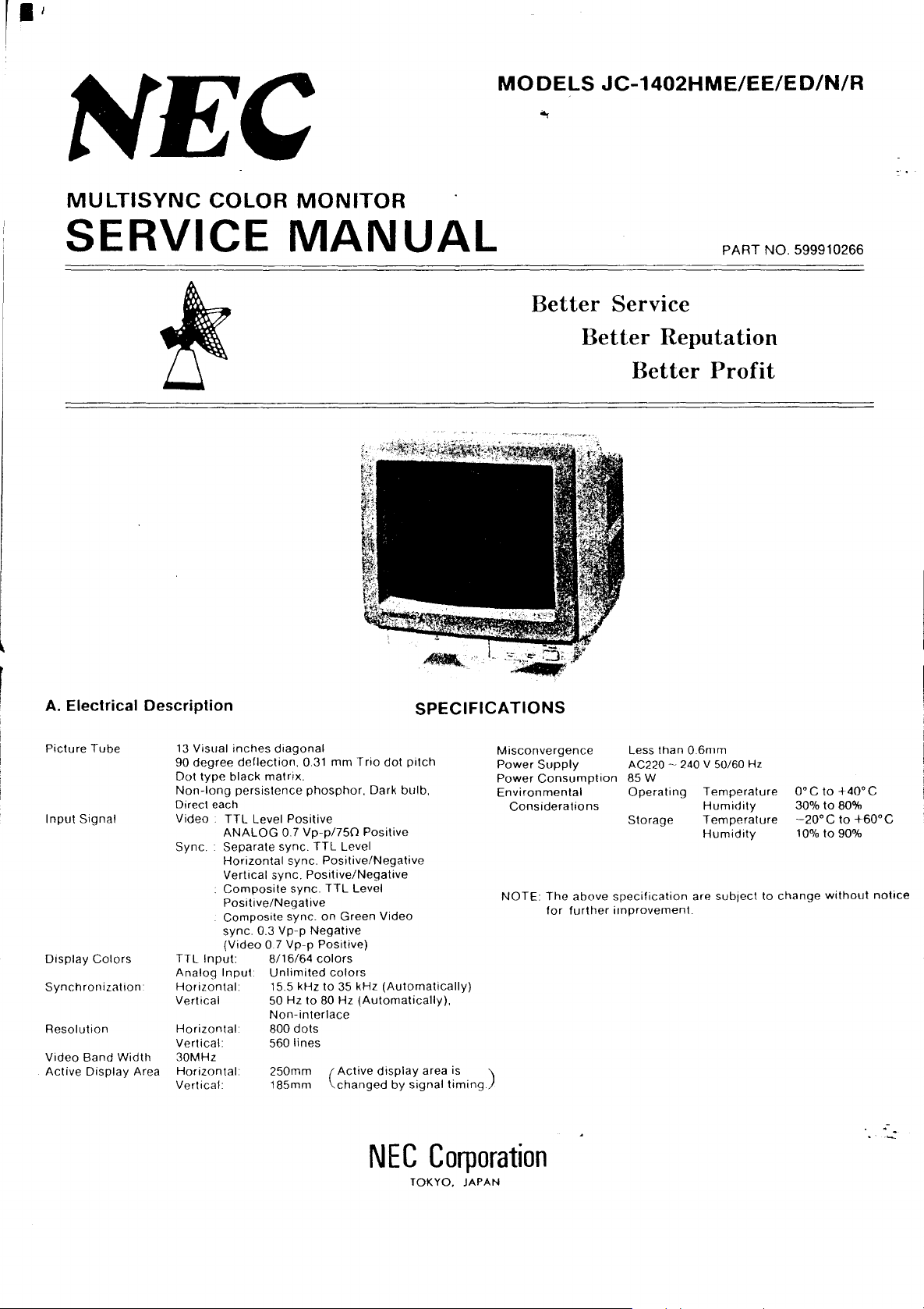
A.
Electrical Description
Picture
Tube
Input
Signal
Display
Synchronization
Resolution
Video
Active
Colors
Band
Display
Width
Area
13
90
Dot
Non-long
Direct
Video.
Sync.
TTL
Analog
Horizontal
Vertical
Horizontal
Vertical:
30MHz
Horizontal
Vertical:
Visual
inches
degree
deflection.
type
black
persistence
each
TTL
ANALOG
Separate
Horizontal
Vertical
Composite
Positive/Negative
Composite
sync.
(Video
Input:
Input
diagonal
matrix.
Level
Positive
0 7
sync.
sync.
sync.
sync.
sync.
0.3
Vp-p
0.7
Vp-p
8/16/64
Unlimited
15.5
kHz
50 Hz
Non-interlace
800
dots
560
lines
250mm
185mm
0.31
mm
Trio
dot
phosphor,
Vp-p/750
TTL
Positive/Negative
Positive/Negative
on
Negative
Positive)
colors
to
to
80
Dark
Positive
Level
TTL
Level
Green
colors
35
kHz
Hz
(Automatically),
Active
(
changed
Video
(Automatically)
display
SPECIFICATIONS
Misconvergence
Power
Power
Environmental
NOTE:
by
pitch
bulb,
signal
area is )
timing.
Supply
Consumption
Considerations
The
above
for
further
Less
than
AC220
~.
85W
Operating
Storage
specification
improvement.
0.6mm
240 V
50/60
Temperature
Humidity
Temperature
Humidity
are
sublect
Hz
to
change
O°C
30%
'-20°C
10%
to
+40°C
to
80%
to
to
90%
without
+60°C
notice
.-
..::
NEC
Corporation
TOKYO.
JAPAN
'. ,
'J
AC
220
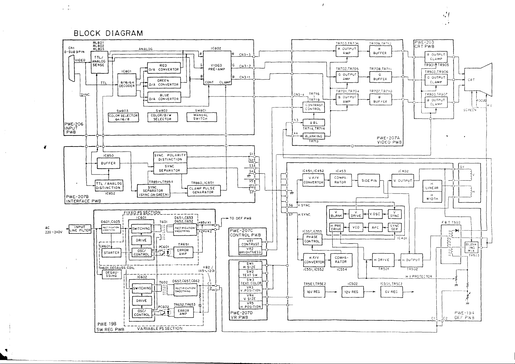
BLOCK
CN,
O-SUB
9P'N
r
~.-
L--4-~T~T~L-~Df2g~~~~~D/A
I'YNC
"","'
PWE-206
..
1_~_~_U_8_T
__
()
_ J
L{
PW
E _
2078
~~~~=_~O~'~S_T_'N_C_T_'_O_N
INTERFACE
"'
INPUT
LINE
-240V
ALTER
DIAGRAM
RL80'
RL8Q2
RL8Q3
~iJr;:::=============::r::::::::1
TTL!
ANALOG
SENSE
~
L..-
Sw803
COLOR
64/'618
__
Q_<>
_________________________________ 6 I
-- -0----------------------------------
-
IC850
8UFF
ER
1\f---+---,,1-----~
"
----'4
~
TTL
I
ANALO~
I C85 2 (SY Ne.ON
PW8
rl
r--
ICR60'
:
,I
I
I 1
L.
TH60!.
U OEGAU 1
1.
PWE
SW
___ } ___
060l,C605
;!~::~;.o"
t+~1SWITCHI
___
[STARTER1--
___________________________
OEGAUSS. COIL + 82 /
S5ING'
198
REG
PW8
ANALOG
REO V
D/~
cJ
CONVERTOR
GREEN 1 _
CONVERTOR
IC80'
h .J
___
......JI
L;:j
..
O_I_~
__
C_~_~_~_~_R_T_O_R..J
SELECTOR\ r
J SELECTOR
SWS02
COLOR/8/'"
SY~~ST~NOC\~~~TY
~
SYNC
I SEPARATOR
ITRS51,,-
TRS5.
SEPARATOR
GRE
EN
I
S_Y_N_C
FIXED
PS
r--------------------~
: I
: . ,
I I ,J" 1
J
'"I:
:
i I
:
I
I CONTROL
i I I
I
L
SECTION
C60,
I I T601
NG
[J
_I
ORIVE"
I ?C601
I I
OSCI
r CONTROL
~l.r-K;--,
tt~-'
-1--IC602--;
sWITCHINGU-]jiO"c"",c~m"l:
'"'"
05C/
to-.
____________________
VARIABLE
~---_olL.._G_E_N_A_R_A_T_O_R_..J
___
I
___________
I i A
i:L_P,",OOTHING
~:2--
:~7~~5~~6:~:
II
::
PC6_02
-
~-t;1
~.:LJ
PS
SECTION
~
~
r--
1--
l I
...
__
t--------+----r'ls::.:?:<
f-----+-----.
TR860,
CLAMP
D65,
,C653
D652,C652
',W"W,ONI
TR6S'
ERROR
-1
AMP
r:
,.",.,.
TR652,TR6}4-3
ERROR
AMP I
,C802
VIDEO
PRE-~MP
~c~oTN~T~_C~L~AM~P~-~~-<Ir---~
R
eN3
G
CN3-2
8
CN3-'
____________
- 3
L I
,---------0--------,
I I
J
SwSO,
MANUAL
S'_"_'_TC_H
__
IC85'
PULSE
I
...l.
}-
I
1+85VK'
fT
-v-
tit
4VK2
:
I
i
..
J
145""201
\
~~--=
l-
I
r~
I
~
':""0-1
!lSs~.b-
~
~5
_______
TO
PWE-207C
CONTROL
L-
_________________________________________________________________
~~7°~~'I~,1
OEF PW8
PWB
VR,
CONTRAST I :
VR2
8R\GHTNES~
5WI
H. 51ZE
SW2
TEXT
SW
S'II3
TEXT
COLOR
VR3
V.POSITlOtJ
VR4
V.
SIZE
VR5
H POS(TION
PWE-207D
VR
PWB
~-_-c}-_-"I
T~hll
I R
:>-J
I '
\-0---J
L"r--
-<:r-
I
I
~--------------~IR
IU'Hl~:~::
CON
I 1
~3
X4
I
~----------------o---------------...l
I
r-
TR
CJNT
jROL
A8L
TR?14, TR?14
8L..lNKING
, TR?13
IC45',IC452
--1
V
FIV
I -ICONVERTOR
~~:
1--<':>2L V SYNC
IC557,IC555
U PHASE \
I I CONTROL I
t
U H
FIV
-jCONVERTOR
less I,
IC552
TR5E I, TR5E2
EJ--
1
TRloo.TRl.')">
OUTPUT \
1
~MP
l~
HT:
5
?~~
~:~~
~P
TR701
TR70~
--He
AST
~~::UT
f
.-------J
r-
IC453
CO~P.l
RATQR
SIDE
PIN
r
V V V
BLANK
~~
DRIVE
~I
~
DRivE
.PRE
l -
COMeA-
I
RATOR
IC554
VCO
V.OSC
A-C
I""
--1
'-IHOR"'E
L-~----
IC502
I
'2V
REG
PWE-207A
VIDEO
PWB
Ie
402
h
rl
V OUTPUT
--
4-~---
SYNC
S~YNC
5EP
(C401
1-
HOUrpUT
TR5l)1
____________
r~5""'2
~H~'~J~:~R~O~TE~-~-T~O~R~~-----r~~
H
LI
NE.lR
H
.,,"
~-I--I
IJ]jr-iLlli'lD-
I
L--.-J
C-.-J'~C2
~+-Jv
I I
}-
,"~,~
iiLl
~~~.J3
"1
P\IJE-194
DEc
?',~a
"'"

I
B.
Mechanical Description (See below diagrams)
1.
Cabinet:
2.
Dimensions:
3.
Tilt
Swivel
Front
- -
,
-'-
LI!
L;::
Range
I-- -
8
5
~
J
Molded
360(W)X372(H)X400(D)
plastic
cabinet
Side
1'----
~
t--
'"
M
!
~r
I
400m1
'LI~J
with
attachable
mm
i
,
tilt
swivel base.
i
4.
Weigtlt:
5.
Controls
6.
Input
7.
Power
In
power
Rear
Front
case
Controls:
Controls:
Signal
Terminal:
cord
of
JC-1402HMEE,
cord
is as
follows.
the
end
16 kg
MANUAL
MODE
COLOR
POWER
BRIGHTNESS
CONTRAST
V.
POSITION
V.
SIZE
H.
POSITION
H.
SIZE
TEXT
TEXT
9 PIN
(SEE
of
-----~y=:==.::.::::j
-1-
SWITCH
SWITCH
MODE
SWITCH
CONTROL
SWITCH
SWITCH
COLOR
D-SUB
PAGE
SWITCH
CONTROL
CONTROL
CONTROL
CONTROL
SWITCH
CONNECTOR
2 FOR PIN
~-
~
(FEMALE)
ASSIGNMENTS)
-
---
---Green
_
..
_n_
Blue: Neutral
-- - Brown: Live
and yellow Earth
.-
•
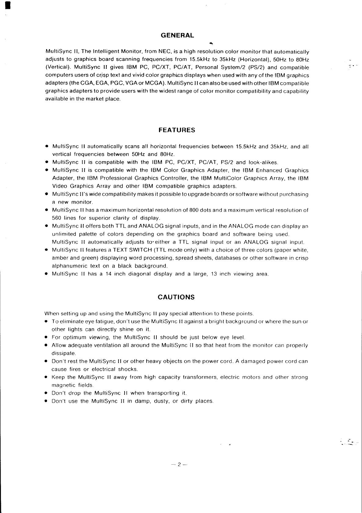
GENERAL
MultiSync
adjusts
(Vertical).
computers
adapters
graphics
available
•
•
•
•
•
•
•
•
to
MultiSync
vertical
MultiSync
MultiSync
Adapter,
Video
MultiSync
a
new
MultiSync
560
lines
MultiSync
unlimited
MultiSync
MultiSync
amber
alphanumeric
MultiSync
II,
The
graphics
MultiSync
users
of
(the
CGA,
adapters
in
the
market
II
automatically
frequencies
II
is
II
is
the
IBM
Graphics
II's
wide
monitor.
II
has a
for
superior
II
offers
palette
II
automatically
II features a
and
green)
text
II
has a 14
Intelligent
board
II
gives
crjsp
text
EGA,
PGC,
to
provide
place.
between
compatible
compatible
Professional
Array
and
compatibility
maximum
clarity
both
TTL
of
colors
TEXT
displaying
on a black
inch
Monitor,
scanning
IBM
and
vivid
VGA
users
scans all
50Hz
with
with
Graphics
other
horizontal
of
and
depending
adjusts
SWITCH
word
background.
diagonal
from
frequencies
PC,
PC/XT,
color
or
MCGA).
with
the
horizontal
and
the
IBM
the
IBM
IBM
compatible
makes
it
resolution
display.
ANALOG
on
to'
either a TTL
(TTL
processing,
display
NEC, is a
graphics
widest
high
from
PC/AT,
displays
MultiSync
range
15.5kHz
II
of
FEATURES
frequencies
80Hz.
PC,
PC/XT,
Color
Graphics
Controller,
possible
signal
the
mode
the
graphics
to
upgrade
of
800
inputs,
graphics
signal
only)
spread
and a large, 13
resolution
to
35kHz
Personal
when
can
also
color
monitor
between
PC/AT,
Adapter,
IBM
MultiColor
adapters.
boards
dots
and a
and
in
the
board
input
with a choice
sheets,
databases
inch
color
monitor
(Horizontal),
System/2
used
with
be used
compatibility
15.5kHz
PS/2
and
the
or
software
maximum
ANALOG
and
software
or
an
of
viewing
(PS/2)
any
of
with
other
and
look-alikes.
IBM
Enhanced
Graphics
without
vertical
mode
being
ANALOG
three
colors
or
other
area.
that
automatically
50Hz
and
compatible
the
IBM
IBM
compatible
and
35kHz,
Array,
purchasing
resolution
can
used.
signal
(paper
software
to
80Hz
graphics
capability
and
Graphics
the
IBM
display
input.
white,
in
crisp
all
of
an
When
setting up
•
To
eliminate
other
•
For
Allow
•
dissipate.
•
Don't
cause
• Keep
magnetic
•
Don't
•
Don't
lights
optimum
adequate
rest
the
fires
the
MultiSync
fields.
drop
use
the
iJnd
using
eye fatigue,
can
directly
viewing,
ventilation
MultiSync
or
electrical
the
MultiSync
MultiSync
II
the
don't
shine
the
MultiSync
all
II
or
shocks.
away
II
II
MultiSync
use
the
on
it.
around
other
heavy
from
high
when
in
damp,
CAUTIONS
II
pay
special
MultiSync
II
should
the
MultiSync
objects
capacity
transporting
dusty,
or
-·2-
attention
II
against a bright
be
just
below
II
so
that
on
the
power
transformers,
it.
dirty
places.
to
these
points
background
eye level.
heat
from
the
cord. A damaged
electric
motors
or
where
monitor
power
and
the
can
other
sun
properly
cord
can
strong
or
.-
I
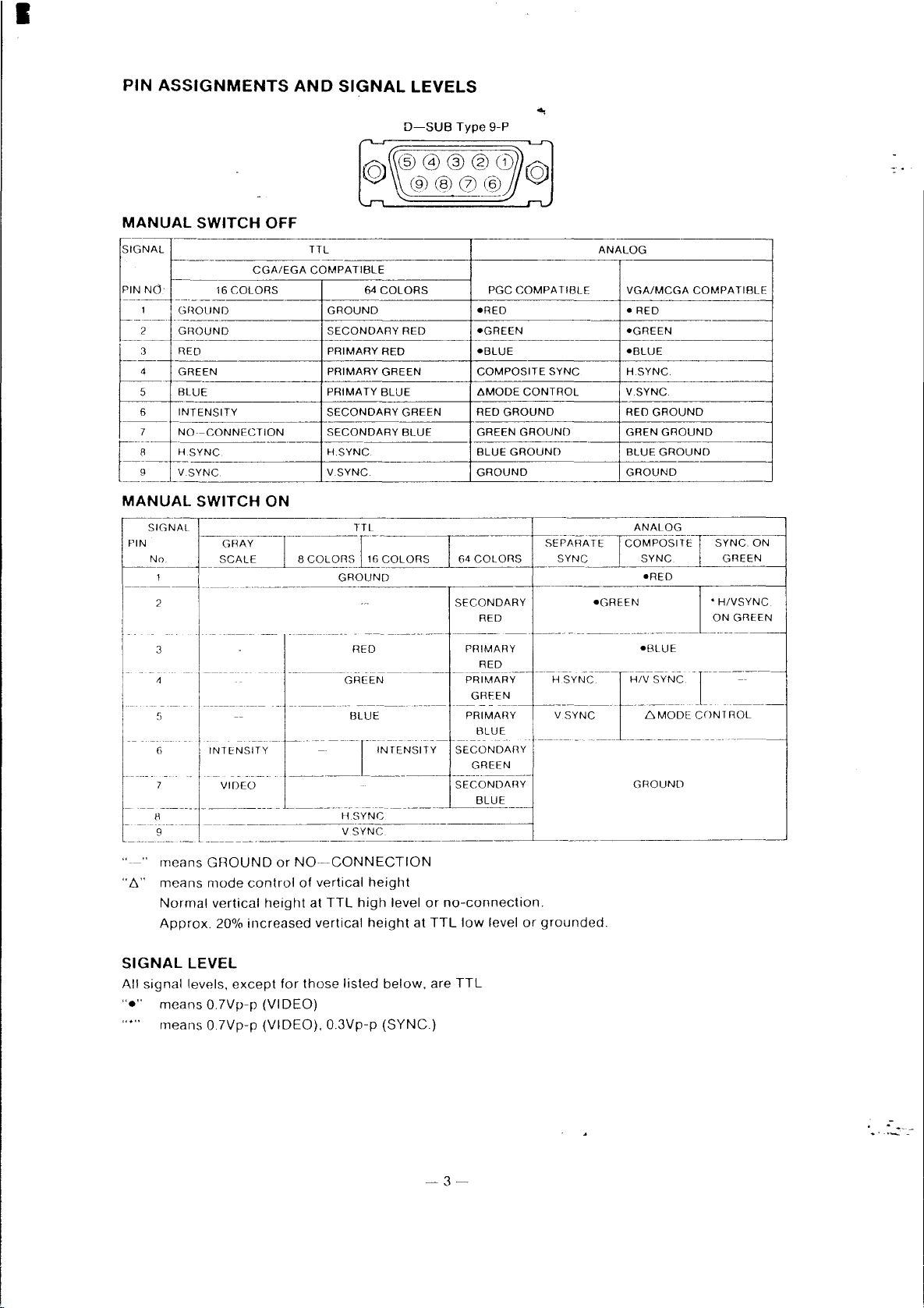
PIN
ASSIGNMENTS
AND
SIGNAL
LEVELS
MANUAL
SIGNAL
PIN
Nd
Gf
2 GR
3 RE
4 GR EEN
5
BL
6
IN
MANUAL
---,,------------------------
SIGNAL
PIN
No
SWITCH
CGA/EGA
16
COLORS
---------
10UND
-----
OUND
0
UE
TENSITY
------------
--CONNECTION
SYNC
YNC
SWITCH
OFF
-_._-
ON
TTL
COMPATIBLE
64
f--
GROUND
SECONDARY
PRIMARY
PRIMARY
PRIMATY
SECONDARY
SECONDARY
H.5YNC
V.SYNC
D-SUB
@@@@Ci)
(9'J@0@
COLORS
RED
RED
GREEN
BLUE
GREEN
BLUE
Type 9-P
ANALOG
PGC
COMPA
TIBLE
-RED
-GREEN -GREEN
-BLUE
COMPOSITE
6MODE
RED
GREEN
BLUE
GROUND GROUND
CONTROL
GROUND
GROUND
GROUND
--------------
SYNC
---
f----------------
VGA/MCGA
- RED
-BLUE
H.SYNG.
V.SYNC
RED
GROUND
GREN
GROUND
BLUE
GROUND
COMPATIBLE
--------,
2
3
6
11
9
______
_____
"
means
"6"
means
Normal
Approx.
SIGNAL
All
signal
"e"
means
means
-----
--------
-----
-_.
-------
INT
ENSITY
VIDEO
___ _ ________________________________
GFlOUND
mode
vertical
20%
LEVEL
levels.
except
0_7Vp-p (VI
07Vp-p
----.-~-
-------V-SYNC
or
NO-CONNECTION
control
height
increased
for
DEO)
(VIDEO).
-GREEN-----
._-
-------[-
H
of
vertical
at
TTL
vertical
those
listed
0_3Vp-p
RED
-------
BLUE
-IN-rEt,J.5ITY-
-------~
SYNC
height
high
height
below.
(SYNC.)
level
SECONDARY
PRIMARY
--p~~~~~y--
_._----
----
PRIMAflY
SECONDAfW
-----
SECONDARY
or
no-connection_
at
TTL
low
are
TTL
RED
RED
- -
-----
BLUE
GREEN
------
BLUE
level
-
-H
SYNC----
--------
V
L-
__________________
or
grounded_
SYNC
-GREEN
- - -
l
-BLUE
H/V
S-YNC - r
--
LiMODE
---
- -
GROUND
----------
- -
CONTROL
----
--
•
HIVSYNC
ON
GREEN
--
--::.---
------
---
----'
-3-
.-

•
TIMING
CHARTS
SEPARATE SYNC.
COMPOSITE
SYNC.
HORIZONTAL
VERTICAL
HORIZONTAL
VERTICAL
I"
____
~I
I~"_c
....
J2i
0
1_.
..
I
..
___
VIDEO
..
VIDEO
o
o"--
..
R
o
__
u
J
u,-----
..
! Sync. Polarity: Positive/Negative
I
.....
I •
.-=E'-1.1
~U
r--
COMPOSITE
SYNC. &
VIDEO
HORIZONTAL
VERTICAL
PRESET
r--'---~'-------:--
----_.
r--------
f---.-~--
f--
t---g.J1.2..~.
r--..Qp~--
--------
._---
r------~--
r--.-----~
1-----_.
REMARKS
IH
A
/lS
B
I'S
E
/lS
Iv
---
Oms
P
ms
Q
ms
R
ms
S
ms
TIMING
COMPATIBLE
1------.--
---------
r-------
-
---""---
1---
-----~
r----
CGA
15.85kHz
63
4.2 4.9
--
7.2 1.6 2.8 1.89
45
6.6 0
61
Hz
..
----~
16
.4
00.75 0.6
1.525 0.08
12.6
2.2 0
----
SEPARATE
SYNC.
H.
POSITIVE
V.SYNC
POSITIVE
--
SYNC.
Sync. Polarity: Positive/Negative
.~
(SYNC.
ON
GREEN)
-4~1------~'------~j
>-----_._.-
-----~---
'."
...
-
---~
I
---.....I-
-;~-
.-~-----'
Sync. Polanty: NegatIve
EGA
COMPATIBLE
22kHz
--_._.
45.5
----------_.
----------
39 25.6 25.17
60
Hz
--------
16.68 16.6 14.27 14.27 16.68
.-----
16
SEPARATE
SYNC.
H.
SYNC.
POSITIVE
V
SYNC.
NEGATIVE
PGC
COMPATIBLE
30.48kHz
33
--
4.5
---
0.1
60
Hz
0.07 0.064
2.12
13.05
1.36 1.2 0.41
HIV
COMPOSITE
SYNC.
----~---------------
1.88
11.126
SEPARATE
SYNC.
H.
SYNC.
POS!TIV.E
V.
SYNC·
NEGATIVE
-4-
VGA/MCGA
COMPATIBLE
31.5kHz
31.77
3.77
0.94
70Hz
0.064
._---
1.08 1.02
12.716 15.246
SEPARATE
SYNC.
H.
SYNC.
NEGATIVE
V.
SYNC.
POSITIVE
L.....-........_~
--
~
I
-----
60Hz
0.064
0.35
SEPARATE
SYNC.
H.SYNC.
NEGATIVE
V.
SYNC.
NEGATIVE
__
--
.-

•
ADJUSTING
Fig. 1
THE
REAR
MANUAL SWITCH
CONTROLS
"'I
COLOR MODE SWITCH
o
MANUAL
This
switch
selects
OFF,
MultiSync
resolution
When
(8/16/64)
SWITCH_ (see
8
This
assignment
Refer
e
One
compatible
SWITCH
and
this
switch
needed
MO
DE
switch
to
the
COLOR
of
tile
four
graphics
as
of
user
shown
D SUB 9PIN TYPE (TTUANALOG)
SWITCH
either
the
IBM
mode
when
II
automatically
color
requirements
is
ON,
by
the
No_
00
the
graphics
below)
user
works
of
must
adapter
in
the
IBM
manually
SWITCH
selects
either
the
gray
scale
gray
scale_)
manual
MODE
color
~----
8
____________________
16
16
64
accompanying
SWITCH
configurations
adapters_
below
..
------
-----------------+-----------
colors
colors
colors
--
colors
The
-
-----
COLOR
with
low
with
IBM
------------------
---------------------------'---------------
the
[8/16(NEC)/16(IBM)/64]
proper
-----
---------
MODE
intensity
brown
OFF
or
the
IBM
mode
compatible
select
being
used
or
color
graphics
configuration
yellow
the
manual
and
adjusts
graphics
the
mode
with
the
with a TTL
adapter
can
be
----"~-------~
COLOR
-+
____
------'-----'-------
for
mode
itself
adapter
(gray/color)
MODE
signal
information
must
be
selected
selected
MODE
8
----'-
_____
16
(NEC)
16
(IBM)
64
when
ON_
to
the
being
and
SWITCH
input.
(See
on
by
using
SWITCH
When
this
switch
scanning
used_
the
and
the
when
the
--l
frequency,
number
APPENDIX B pin
input
COLOR
signal.
using
COLOR
of
non-IBM
is
colors
MODE
MODE
Note
This
Refer
switch
to
the
should
user
be
set
manual
correctly
accompanying
in
relation
the
to
the
grapllics
-5-
input
adapter
signal
for
of
the
~raphics
information
adapter
on
the
input
used_
.-
signal_

•
ADJUSTING
THE
FRONT
~
CONTRAST CONTROL
BRIGHTNESS
POWER SWITCH
TEXT COLOR SWITCH
CONTROLS
CONTROL
• POWER
Used
to
turn
When
the
power
•
BRIGHTNESS
Used
to
adjust
o
CONTRAST
Adjust
8
Adjust
display
o
the
display
V.
POSITION
this
knob
position;
V.
SIZE
o
SWITCH
the
Power
is
ON,
the
CONTROL
the
picture
CONTROL
to
the
CONTROL
for
the
turn
it
counterclockwise
CONTROL
o
V.
SIZE CONTROL
H.
POSITION CONTROL
ON
or
OFF.
power
LED
indicator
brightness
contrast
proper
of
preferred
vertical
the
position
for a lower
is lit.
screen.
by
the
user.
of
I
the
display.
display
TEXT SWITCH
H.
SIZE SWITCH
Turn
the
position.
knob
clockwise
for a higher
Adjust
this
turn
it
counterclockwise
o H.
Adjust
display
POSITION
this
to
knob
knob
the
for
for
right;
the
proper
for a smaller
CONTROL
the
proper
turn
it
counterclockwise
vertical
horizontal
size
display.
of
the
position
to
reposition
display.
of
the
~6~
Turn
display.
to
Hie left.
the
Turn
knob
the
clockwise
knob
clockwise
for a larger
to
reposition
display;
.-

•
• H.
Adjust
display
4D
This
When
below),
When it is
Note
The
CD
Use
Also
is selected (see No.2) regardless
SIZE
this
can be
TEXT
switch
it
is ON,
regardless
TEXT
TEXT
this
switch
use
this
SWITCH
switch
for
made
SWITCH
controls
the
OFF, the
SWITCH
COLOR
to
select the
switch
the
horizontal
wider.
- .
the
text
mode
text
will
appear
of
the
colors
color
of
the
works
only
SWITCH
text
to
select
the
size
of
of
the
MultiSync
in
the
of
the
software
software
in the
color-green,
gray
of
TTL
scale
the
program
position
display
color
mode.
color-green,
preferred.
displayed
program
being
amber
of
the
II.
or
by
being
used
paper
amber
TEXT
Wh~n
this
the
TEXT
used.
will
be
displayed.
White-when
or
paper
SWITCH.
switch
white-when
COLOR
the
TEXT
is ON, the
SWITCH
SWITCH
the
gray
width
of
(see No.12
is ON.
scale
mode
the
-7-
.-

•
THE
METHOD
FOR
REMOVING
Screw
AND
"a"
MOUNTING
Base A
CD
Insert 3 mounting
table
A. -
®
Arrange
on
the
bottom
Screw
the
philips
head
THE
TILT
the 3 male
of
the
table A to
screwdriver.
SWIVEL
screws
screws
Set
the
set
BASE
"a"
into
holes
"a"
into
the
in
correct.
driving 3 screws
on
the
female
"a"
turnin~.
Screws
with
a
[zJ
Base B
Base A
Square
/f
hole
of
rear
cover
(I)
(2)
Align
the
B,
into
Both
tables
degrees
arrow
the
table
are
clockwise.
of
both
A as
fixed
tables
shown
firmly
A and B,
on
the
by
turning
and
left.
the
put
table
the
B 180
table
0
[1]
[_{lin
case
you
Sequence
remove
from
[11--
the
OJ
turning
.
table,
take
a reverse
-8-
After
completing
Sequence
It is
recommended
coming
face
NOTE:
Please
horizontally.
avoid a harsh
OJ
to
-
the
the
ill
that
printing
,place
handling
attachment
the
the
Set
side
to
of
the
set in its
should
on
the
turn
the
turning
proper
be used
turning
Set
vertically
table
position.
with
table.
in
its
or
.-
I
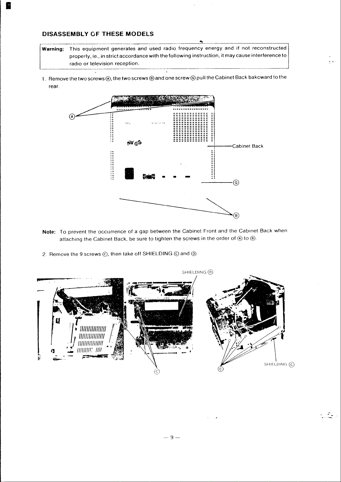
DISASSEMBLY
Warning;
1.
Remove
rear.
This
equipment
properly,
radio
or
the
two
OF
THESE
ie.,
in
television
screws
generates
strict
accordance
reception.
0,
the
,.
,-
MODELS
and
two
screws ® and
'"
,wG~
I
used
with
hid
radio
the
following
one
• •
frequency
screw@
...
...
. .
-
energy
instruction,
pull
the
Cabinet
it
and
may
if
not
cause
Back
inet Back
©
reconstructed
interference
bakcward
to
to
the
F
Note:
2.
Remove
To
prevent
attaching
the 9
,'r
i/._
the
the
screws
"
lillI/III
Cabinet
III/III
/11/1111111/1111
.
/1111111111111/11
'2.
II
III
III!,'
/III
occurrence
Back,
©,
then
/,-
'
'
~
I
of a gap
be
lake
between
sure
to
tighten
off
SHIELDING © and
the
the
Cabinet
screws
@.
SHIELDING
Front
in
the
®
and
order
®
the
Cabinet
of 0 to
®
Back
when
.-
--
9-
I
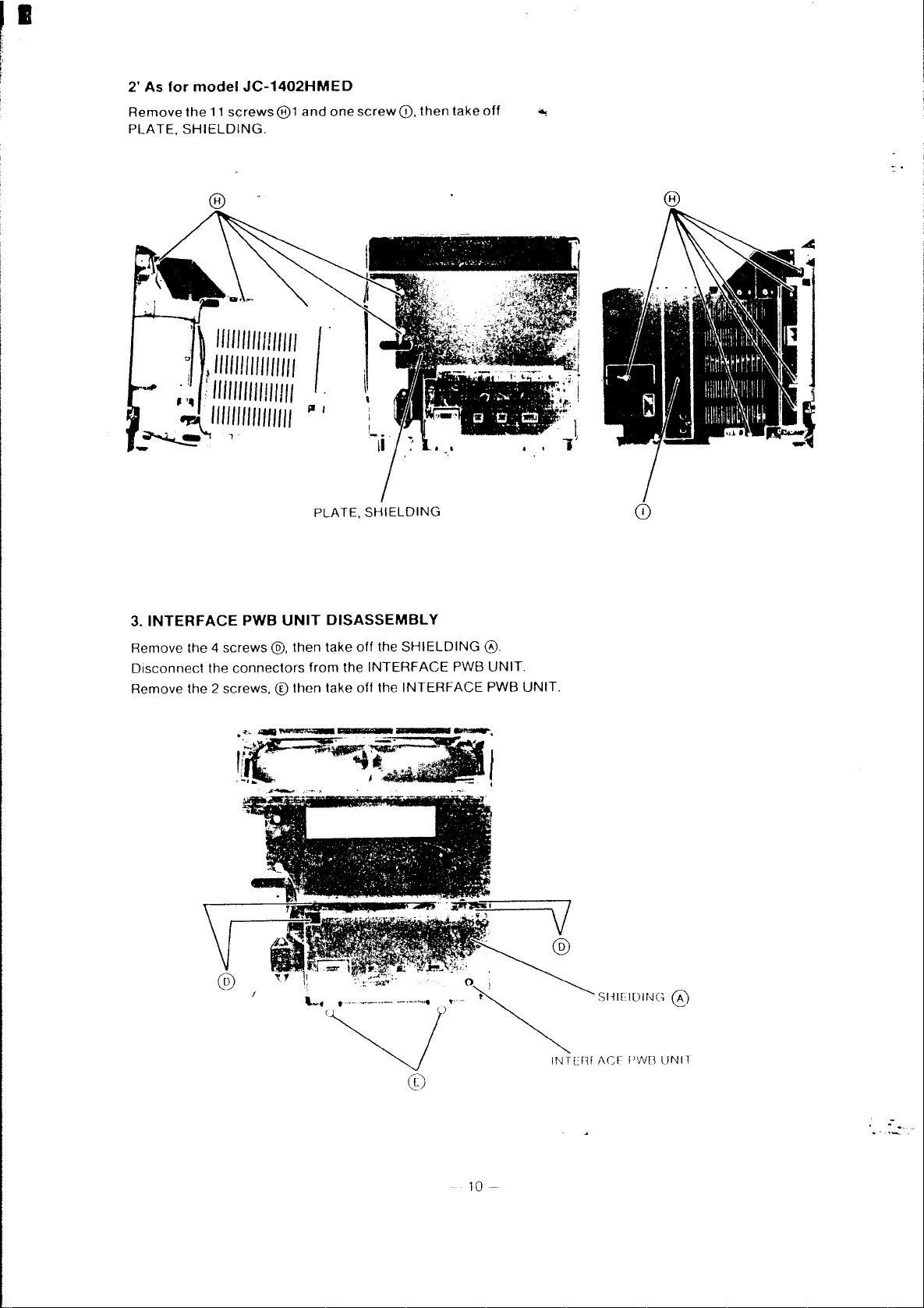
2' As
for
Remove
PLATE,
model
the
JC-1402HMED
11
screws@1
SHIELDING.
and
one
screw
CD,
then
take
off
~
1111111111111111
}
1111111111111111
;
1111111111111111
1111111111111111
/.
~
I
PLATE, SHIELDING
3.
INTERFACE
Remove the 4 screws
Disconnect
PWB
the
connectors
UNIT
@,
then take
DISASSEMBLY
from
Remove the 2 screws, ® then take
off
the
the
INTERFACE
off
the
I r
~
......
,
..
_
..
't~~
..
".
....
,:-
SHIELDING
PWB
INTERFACE
,,~.
~
~_
@.
UNIT.
PWB
' •
UNIT.
10-
.-
•
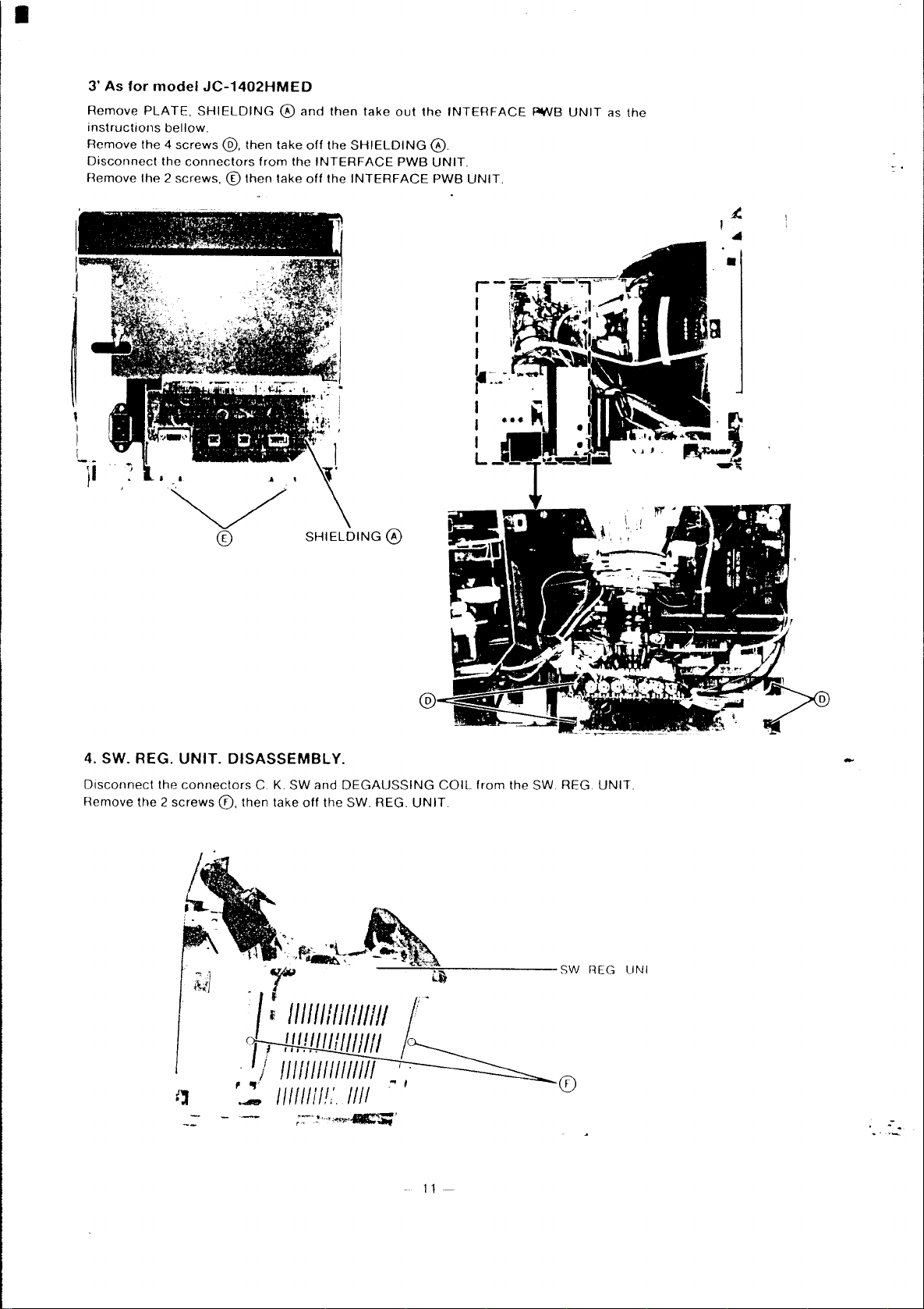
3'
As
for
Remove
instructions
Remove
Disconnect
Remove
••
t •
~
¥
,~·,,·~#~·
••
1t
)1
model
PLATE,
the 4
the 2 screws,
~ . ~
.......
JC-1402HMED
SHIELDING 0 and
bellow.
screws
@,
then
take
the
connectors
t - I
/;"'~'~~~:~}~
~'ft~I'f.":~"~(~"~
CD
"
from
then
.-
:
take
.,.. , .,
.'
_
........
then
off
the
the
INTERFACE
off
the
,,;..(.
.
'J
take
out
SHIELDING
PWB
INTERFACE
the
INTERFACE
0.
UNIT.
PWB
UNIT.
r-
I
I
I
I
1.- -
r
..
I
I
I
L
· .
f¥lB
UNIT
as
the
,
•
~
...
4. SW. REG.
Disconnect
Remove
the
the 2 screws
~
®
UNIT.
DISASSEMBLY.
connectors
0,
then
C.
K.
SW
take
off
'
..
'.,r---. , __
SHIELDING
and
DEGAUSSING
the
SW. REG.
-L
Ii+
4~~~~
@
COIL
UNIT.
from
the SW. REG.
-
UNIT.
.,
~/II
II
filII
'I
i ! ! ! ! ! ! Ill!
/
111/111111111111
f"":
II I III!
/I.'.
III/II
1///
1I11-'---='::"'-'ii,,:;'i,
.~
----
I
11-
SW
®
Fl
EG
LJ
N I
.-
•
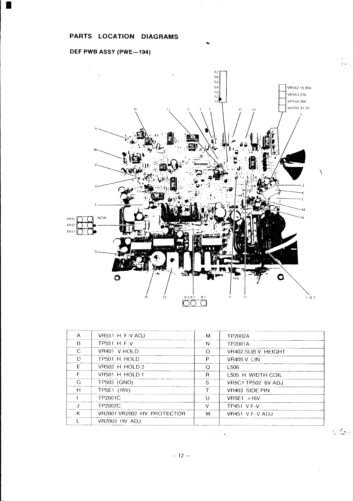
PARTS
DEF
PWB ASSY
LOCATION
(PWE-194)
DIAGRAMS
S7
S6
S"
S~
S3
S7
SI
VR552
VRS,,]
15 8Sk
nk
\
l11il@NON
RIi?
mu
A VR551 H. F-V
--"--
--------
B TP551
.-.------
C VR401
--.--
o TP501 H.
~-.----
E VR502
~--
F VR501
...
_-------
G TP503
H
~~
---~Fl!~~-.
- -
------------~--.------
H.
F-V
-....
V.HOLD
HOLD
H.
HOLD
H.
HOLD
ADJ
--
----.-------
---
-.-
-----.--------.---------
.. ------------------
.- -
._---------------------
-.-------.----.-----~--------.-
-
..
(GND)
TP5E1 (16V)
-_·_·_·_-----------_·_------_·_--+----<1-----
R
o
K3
K?
K 1
f'
00::::0
---
------
M TP2002A
--
--
-.----
.. -..
---------
2 0 L506
--
1 R L505
-~--.-
----.-
t---.----
---
------
.
---
-~--.-.-
-----
N TP2001A
.. -.----.---.------------------1
0 VR402
P VR405 V
..
S VR5C1 TP502 6V
T VR403
-----
---------------------_._--1
--
--
-~----------------.--.----~
-
o
SUB
V.
LIN
.---------------------1
H.
WIDTH
...
--.-----.------.-------1
SIDE
PIN
f B T
HEIGHT
COIL
ADJ.
.-
--
12-
I
1
2
3
4
5
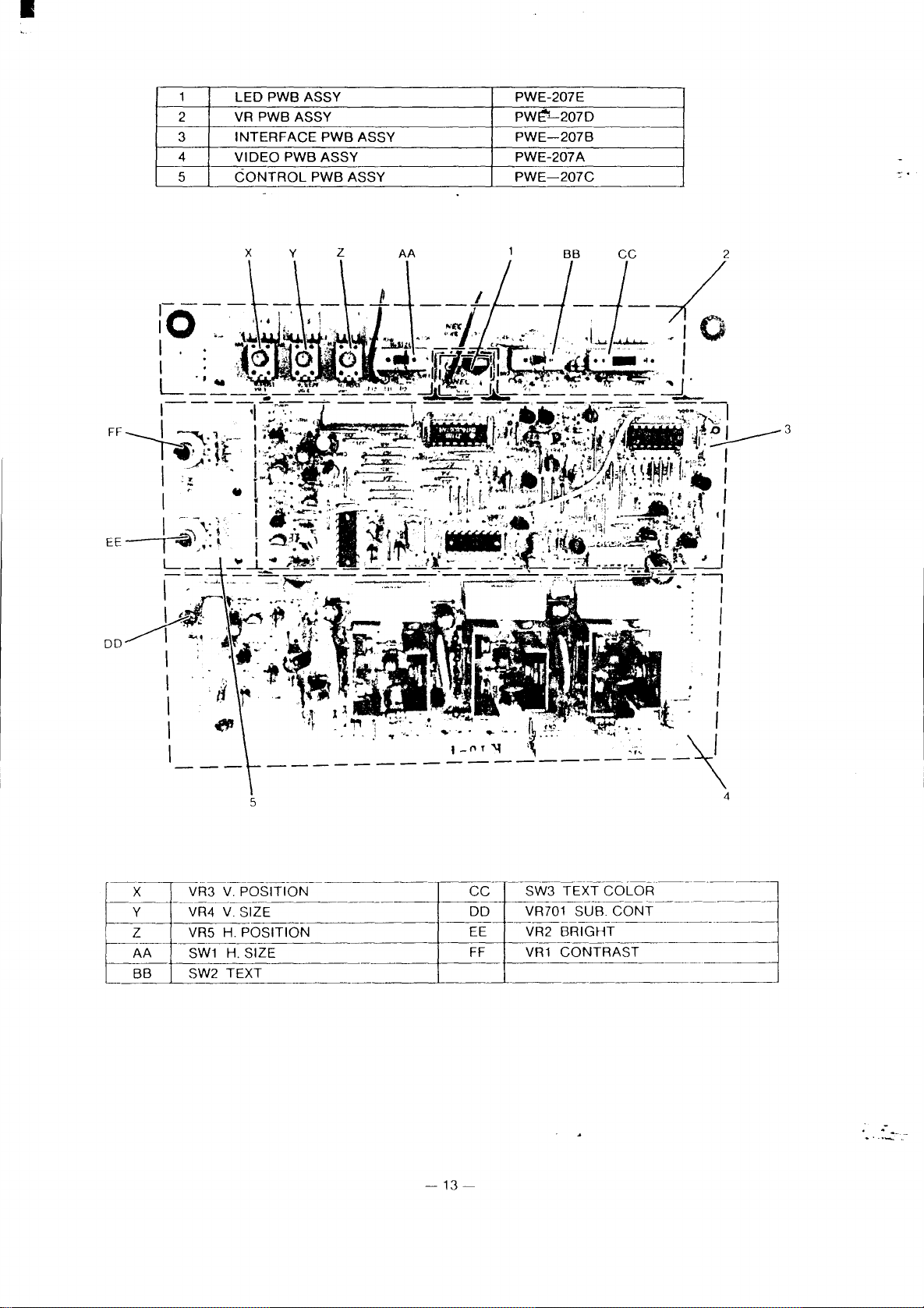
LED
PWB ASSY
VR
PWB ASSY
INTERFACE
VIDEO
PWB ASSY
CONTROL
PWB
ASSY
PWB ASSY
PWE-207E
PW~i-207D
PWE-207B
PWE-207A
PWE-207C
5
~-~----,-"------------~--~-
X VR3
f------1,-~-
Y VR4 V SIZE
f--~~+--------------------
Z VR5 H. POSITION EE VR2
r------
AA
r--·~-r-~~-~--~------4_--
BB
V.
POSITION
--.----------.---~~--+-------.~~
SW1
H.
SIZE
SW2 TEXT
-----------'-.-~-'-----.-----
.----j~----
-13
----
CC
DD VR701 SUB.
FF
-
---~---
SW3 TEXT
----.~-------
--~--~------------------
VR1
t-------~----·-·
------
COLOR
CONT
BRIGHT
CONTRAST
---.-~---.-
.-----.------~-
.-

I
INPUT
GG
HH
II
PWB ASSY
LL
KK--"
JJ
SW803
SW802
SW801
(PWE-206)
COLOR
MODE
MANUAL
MODE
GG
HH
JJ
KK
LL
"
VR803
VR802
VR801
CRT
-----
MM
NN
~~-
t
------"--
PWB ASSY (PWE-203)
MM
,
CRT
SOCKET
SS
-
VR904
VR905
-~::~~-------------.------
~
-"'-"----------------------
TT
I~Q
.------~-
--
----+----------------1
RR
-
~~--
------
VR902
VR903
TP901
TP902
A
.-
-
14
--

I
SW. REG. PWB ASSY (PWE-198)
CONNECTOR"K"
CONNECTOR"C"
e·
~
/ VR652 REF
'L
..
·11
.LV-VR653
,'t:-I
,
if'-
~II
•
V.
LIMITER
CONNECTOR
"DEGAUSSING
CONNECTOR"SW'
COIL"
.-
-
15-

•
ADJUSTMENT
PROCEDURE
Standard Adjustment Conditions
1)
Power
source
2)
3)
Aging:
Signals:
Video
Unless
Adjust
1. SW. REG.
1)
+B,
(VR651)185V
Adjust
2) t BUM
Note:
3) t
Remove
Adjust
Do
not
BH
(VR652)
This
control
Do
not
(VR653)
voltage:
after
Analog
Analog
Synchronizing
Deflection
otherwise
UNIT
VR651
to
V.limit
C-connector
VR653
to
operate
High
is
permanently
attempt
to
AC220V~240V
leaving
0.6Vp-p
Sync.
specified,
LINE
be
85
be
the
Voltage
readjust.
power
750
on
green
Video:
Synchronizing
TTL
Separate/composite
frequency:
VDC
(C1-Gnd
122 Volts.
SW. Reg.
on
terminal
0.6Vp-p
level
H.
V.
use
signal
Voltage)
unit
control
sealed at
50 Hz.
for
20
minutes
Positive
03Vp-p
Negative
15kHz -35kHz
50
Hz -80
14
itself
factory
polarity
polarity/positive
Hz
(22kHz
without
EGA
any
or
more.
mode).
load.
polarity
2.
Pre-adjustment of DEF PWB
Apply
24V
DC
For
sections
used
as a
1)
I 16V
Adlust
2)
t6Vadjustment
Applya
Adjust
3) I-:lorizontal FIV
Input
Adjust
3)
TESTING
adjustment
VR5EI
resistance
VR5CI
fH
ccc
25kHz
VR551
between
and
for
for
convertor
for
K2
4).
the
EOUIPMENT
16V t 0.05V
load
of
6 t 0.05V
adjustment
hOrizontal
10
±0.05V
and
K3.
JC-1402HMA
DC
between
1001
OW
between
DC
between
(signal 17)
synchronizing
DC
between
INTERFACE
TP5El
TP502
TP551
HC2
and
negative
and
and
and
PWB
the
HC3.
the
ground
polarity
the
ground.
ASSY S connector
ground.
5Vp-p
between
outPlit
S7 and
the
can
also
ground
be
.-
-
16-
•
4)
5)
Vertical
Input
Adjust
High
High
High
FIV
convertor
fv =
60Hz
VR451
for
voltage
voltage
With
DC
voltage
With
DC
Due
(74007891) .
protector
protector
32.0 ±O. W
between
protector
31.8
±0.1 V DC
between
to
DHHS,after
vertical
5.95
TP2001C
TP2002C
3. Main Adjustment
Set
the
Front
external
controls
VR1
CONTRAST:
VR2
BRIGHTNESS:
VR3 V
VR4
V.SIZE
VR5
HPOSITION:
VRs
(as seen
POSITION:
adjustment
synchronizing
±0.05V
setting
1
DC
applied
and
2
applied
and
adjusting
and
switches
from
front)
DC
between
between
the
between
the
VR2001
(signal
as
17)
positive
TP451
TP20().1 A and
ground.
TP2002A
ground.
and
follows
Max.
(fully
At
point
Mechanical
Center
Center
click
click
polarity
and
and
VR2002 seal
unless
otherwise
clockwise)
where
back
center
position
position
12Vp-J'I
the
ground.
the
ground,adjust
the
ground,
with
luster
between
adjust
an
adhesive
specified.
disappears.
S6
and
the
ground.
VR2001
VR2002
for
for
(TSE-385RTV)or
0.3
0.3
±0.05V
±005V
cap
3-1)
Rear
DEF
(1)
(2)
(3)
(4)
SW1
H.SIZE:
SW2
TEXT:
SM3
TEXT
controls
SW801
SW802
SW803
Horizontal
a)
b)
c)
Vertical
Receive
the
High
Receive
voltage
Due
Horizontal
Check
with
PWB
Short
Receive
screen.
Receive
screen.
indented
Voltage
to
L506.
MANUAL:
MODE
COLOR
Adjustment
Hold
signal
signal
is 23.5kV
DHHS,after
that
COLOR
(as seen
Hold
TP501
signal
signal
range.
Adjustment
Raster
the
from
MODE
and
TP503
16
(fH:
18
(IH:
14
(Iv:
60Hz),
16
(fH:
30.48kHz)
with
the the
adjusting
Centering
horizontal
rear)
(GNO).
30kHz)
20kHz)
linearity
Off
Off
Paper
Off
Color
8
colors
turn
vertical
and
CRT
seal
Signal
(small)(left
(left
side)
white
(left
side)
(right
(left
and
adjust
and
adjust
hold
adjust
anode
current
with
an
adhesive
14
(Adjust
is
suitable.
side)
(left
end)
side)
end)
horizontal
horizontal
VR401
high
voltage
cut
at
VGA
If
it is
hold
(1) VR501
hold
(2) VR502 so
and
set
to
the
adjustment
off.
(TSE-385RTV)
H:
31.5kHzlV
extremely
bad,
so
that
that
mechanical
VR2003
or
60Hz, 350
adjust
so
cap
(74007891).
to a suitable
there
there
center
that
line
mode)
is
is
within
the
one
one
high
point
--- 17
.-
--
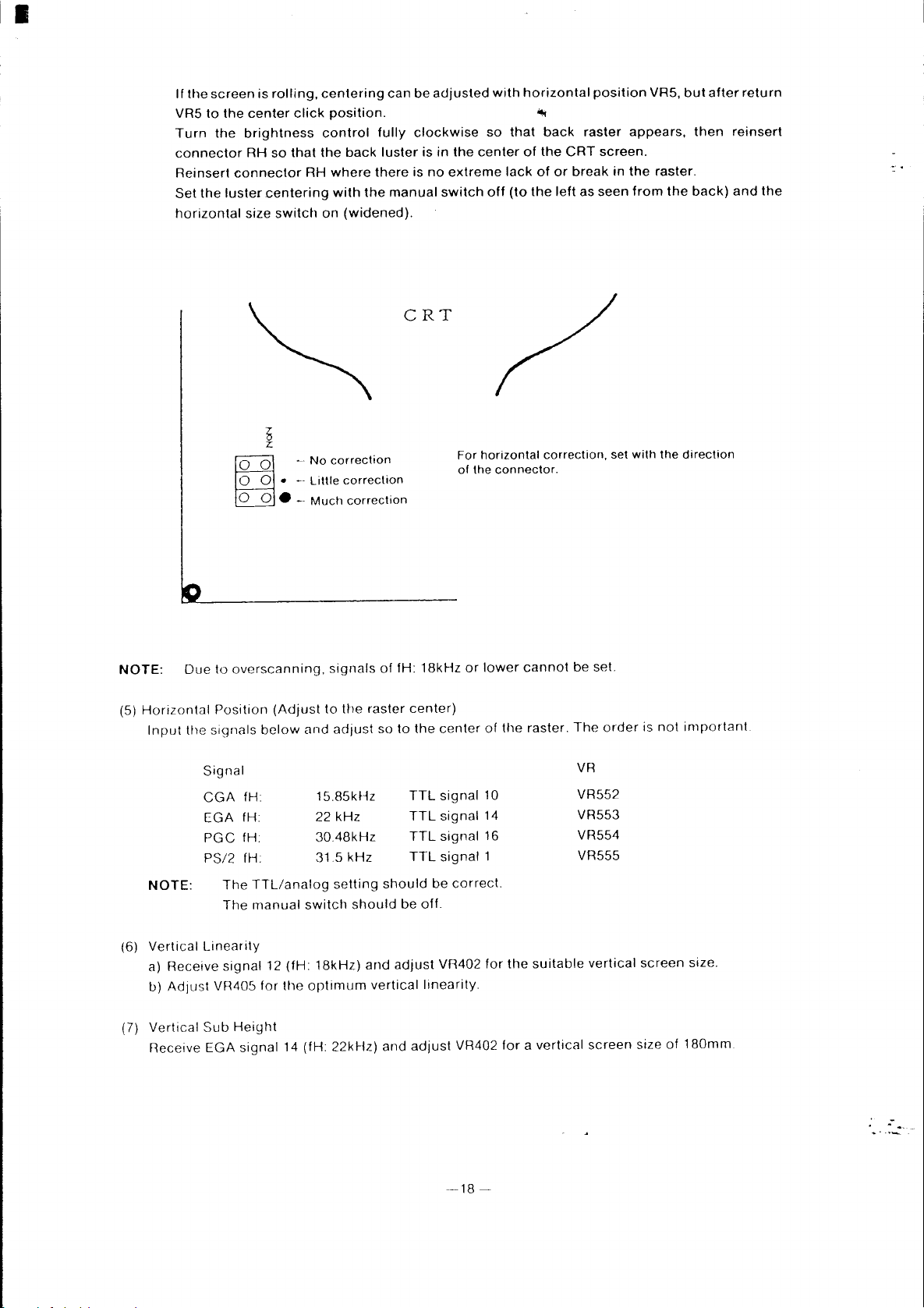
If
the
screen
VRS
to
the
Turn
the
connector
Reinsert
Set
the
luster
horizontal
is
rolling,
center
brightness
RH
so
connector
centering
size
switch
t
z.
1°
0\ . No
o 0 •
o 0 •
click
that
RH
-.
-.
Little
Much
centering
position.
control
the
back
where
there
with
the
on
(widened).
oo""Hoc
correction
correction
can
fully
luster
manual
CRT
be
adjusted
clockwise
is
in
the
is
no
extreme
switch
For
of
with
so
that
center
lack
off
(to
horizontal
the
connector.
horizontal
~
back
of
the
CRT
of
or
break
the
left
correction,
position
raster
screen.
as
seen
appears,
in
the
from
set
with
VRS,
raster.
the
the
but
after
then
back)
direction
return
reinsert
and
the
NOTE:
Horizontal
(5)
Input
NOTE:
(6)
Vertical
a)
IJ)
(7)
Vertical
Receive
Due
the
Signal
CGA
EGA
PGC
PS/2
Linearity
Receive
Ad/ust
Sub
EGA
to
overscanning,
Position
signals
fH
fH
fH.
fH
The
The
signal
VH405
Height
signal
below
TTL/analog
manual
12
for
(Adjust
and
switch
(fH:
the
optimum
14 (fH:
Signals
to
the
adJust so
15.85kHz
kHz
22
30.48kHz
31.5
kHz
setting
should
18kHz)
and
22kHz)
of
fH:
raster
to
should
be
adjust
vertical
and
18kHz
center)
the
center
TTL
signal
TTL
signal
TTL
signal
TTL
signal
be
off.
VR402
linearity.
adjust
or
lower
of
10
14
16
1
correct.
for
VR402
cannot
the
raster.
the
suitable
for a vertical
be set.
The
order
VR
VR552
VR553
VR554
VR555
vertical
screen
is
not
screen
size
of
important.
size.
180mm.
.-
-~18
~
•
(8) Side Pin
(9)
(10)
Adjustment
3-2)
NOTE:
(1)
Cushion
djust
VR403
for
the
Horizontal
Adjust
Horizontal
Receive
250
The
If
correction
range
Initial Settings
VR801
VR701 SUB
VR901 - 903
VR904 - 906 SUB
Linearity
L506 fDr the
Width
EGA
signal 14 (fH: 22kHz) and
±2mm.
horizontal
so
Check
adjustment. In
to
Video:
Synchronizing:
Unless
- 803
size
is
not
that the linearity
of
Video
that the
the signal paterno
Analog
otherwise
of
GAIN
BIAS
Amplitude
Adjustment
optimum
optimum
switch
sufficient
video
particular,
0.6Vp-p
Separate
VR
CaNT
VR
BRIGHT
side
pin
horizontal
should
does
signals
so
specified, use signal 10
VR
with
not
and
for
check
TTL
VRs
VR
be off.
L505,
get worse.
White
are as
LVG-1600.
the level
level
cushion
Fully
Fully
Fully
Fully
distortion.
linearity.
adjust
width
turn
the
Balance
shown
the video signal
with
for
counterclockwise
clockwise
clockwise
clockwise
coil
L505
for a horizontal
L506
linearity
below
the signal
video adjustments.
before
to
coil
performing
be adjusted.
slightly
output
screen size
and
adjust
the
main
level varies
of
within
according
a
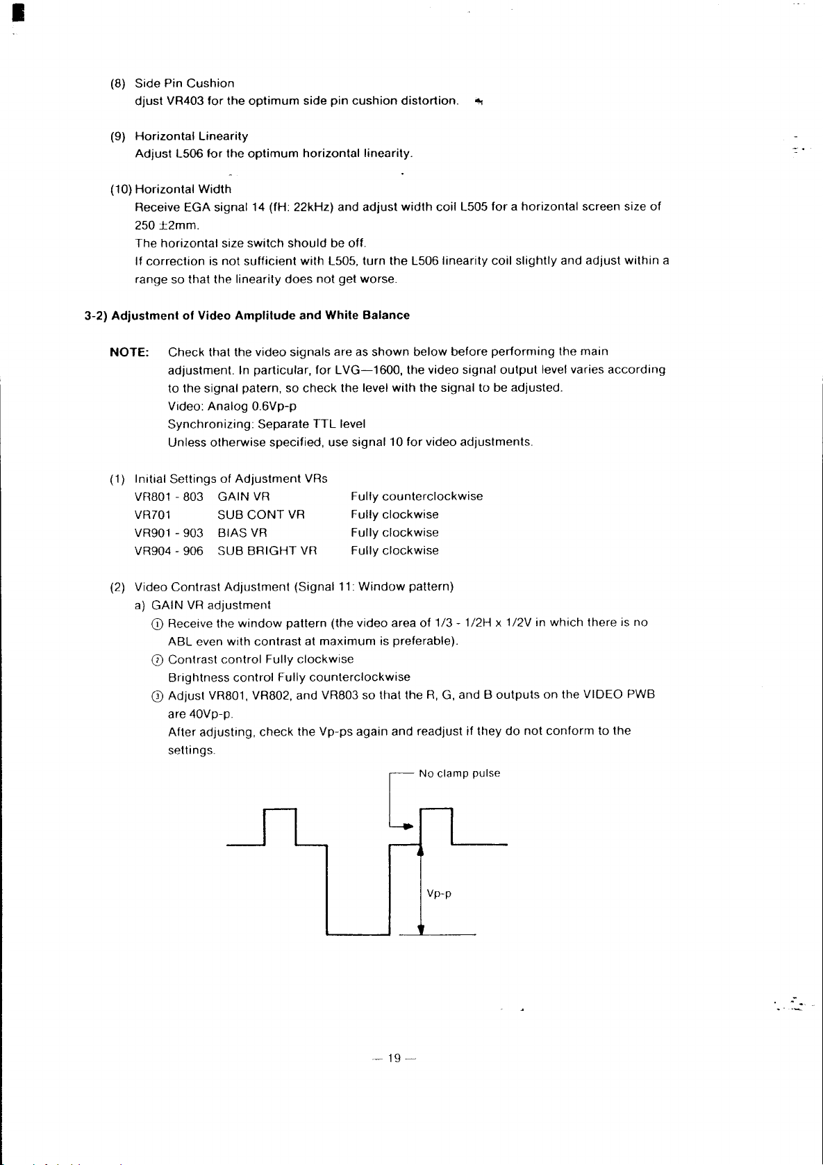
(2) Video
a)
GAIN
CD
o
CD
Contrast
Receive the
ABL
Contrast
Brightness
Adjust
are
After
settings.
Adjustment
VR
adjustment
window
even
with
contrast
control
VR801, VR802, and VR803
40Vp-p.
adjusting,
Fully
control
check
(Signal
pattern
Fully
(the
at
maximum
clockwise
counterclockwise
the
Vp-ps
11:
Window
video area
so
again
pattern)
of
1/3
is preferable).
that the
R,
G, and B
and readjust
Vp-p
- 1/2H x 1/2V in
outputs
if
they
do
not
which
on
the
conform
there is
VIDEO
to
the
no
PWB
-19-
.-
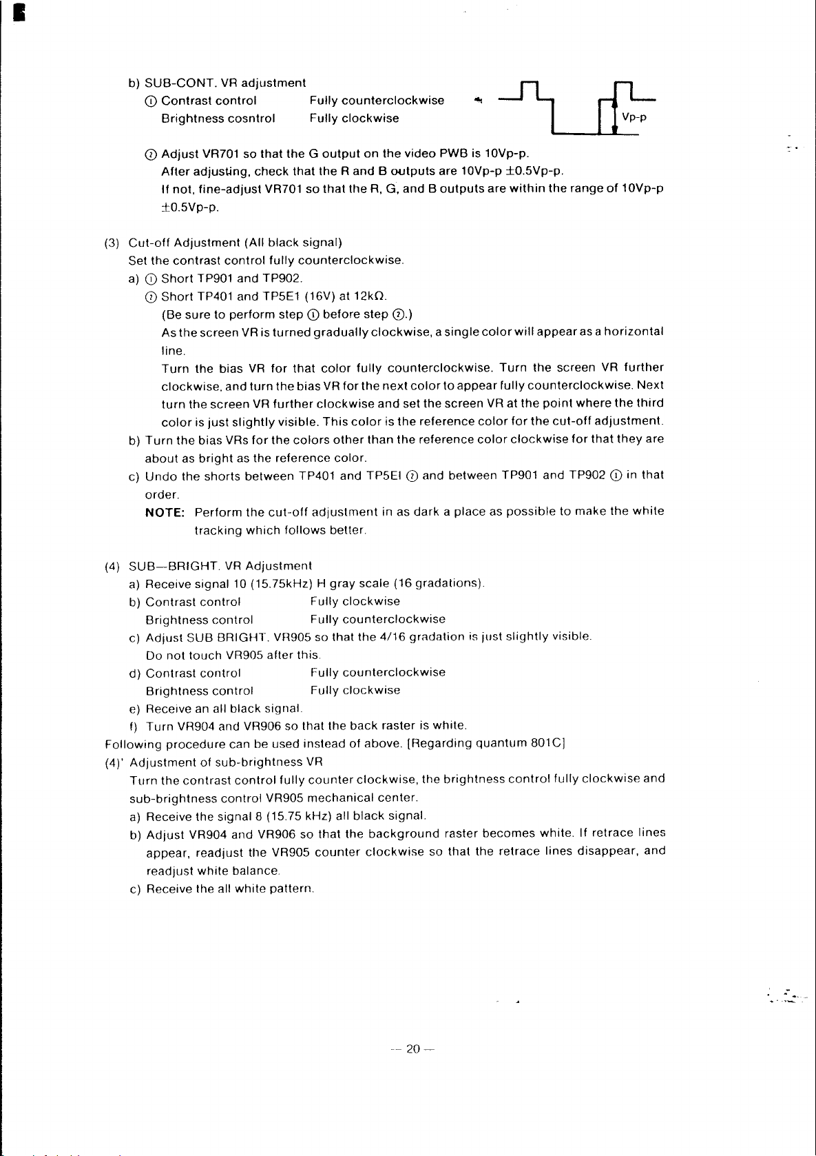
I
b)
SUB-CONT.
CD
Contrast
Brightness
o
Adjust
After
If
not,
±O.SVp-p.
VR
control
cosntrol
VR701
adjusting,
fine-adjust
adjustment
so
that
the G output
check
that
VR701
Fully
counterclockwise
Fully
clockwise
the
Rand B outputs
so
that
the
on
R,
the
G,
video
PWB
is
are
10Vp-p
and B outputs
10Vp-p.
±O.SVp-p.
are
within
the
range
of
10Vp-p
Cut-off
(3)
Set
the
a)
CD
Short
o
Short
(Be
As
line.
Turn
clockwise.
turn
color
b)
Turn
about
c)
Undo
order.
NOTE:
SUB-BRIGHT.
(4)
a)
Receive
b)
Contrast
Brightness
c)
Adjust
Do
not
d)
Contrast
Brightness
e) Receive an all
f)
Turn
Following
(4)'
procedure
Adjustment
Turn
the
sub-brightness
a) Receive
b)
Adjust
appear,
readjust
c) Receive the
Adjustment
contrast
TP901
TP401
sure
the
screen
the
the
is
the
bias
as
bright
the
Perform
tracking
signal
control
SUB
touch
control
VR904 and VR906
of
contrast
the
VR904
readjust
white
(All
control
and
TP902.
and
TPSE1 (16V) at 12kO.
to
perform
VR is
bias
VR
and
turn
screen
just
shorts
VR
slightly
VRs
for
as
the
between
the
which
VR
Adjustment
10 (1S.7SkHz) H
control
BRIGHT.
VR905
control
black
can
be
sub-brightness
control
control
signal
8 (15.75 kHz) all
and
VR906
the
balance.
all
white
black
signal)
fully
counterclockwise.
step
CD
before
turned
for
the
cut-off
after
signal.
used
VR905
VR905
pattern.
gradually
that
the
bias
further
VR905 so
clockwise
visible.
colors
reference
TP401
adjustment
follows
Fully
Fully
this.
Fully
Fully
so
that
instead
VR
fully
counter
mechanical
so
that
counter
color
VR
This
step
0.)
clockwise, a single
fully
counterclockwise.
for
the
next
and
set
color
is
the
other
than
the
color.
and
TPSEI 0
in as
better.
gray
scale
(16
clockwise
counterclockwise
that
the
4/16
counterclockwise
clockwise
the
back
raster
of
above.
clockwise,
center.
black
signal.
the
background
clockwise
color
to
appear
the
screen
reference
reference
and
between
dark a place
gradations).
gradation
is
white.
(Regarding
the
brightness
raster
so
that
color
Turn
fully
VR
color
color
TP901
as
is
just
quantum
becomes
the
retrace
will
appear
the
screen
counterclockwise.
at
the
point
where
for
the
cut-off
clockwise
possible
slightly
801C]
control
and
to
visible.
fully
white.
lines
for
TP902
make
disappear,
as a
horizontal
VR
further
the
adjustment.
that
they
CD
the
clockwise
If
retrace
Next
third
in
that
white
and
lines
are
and
.-
--
20-
I
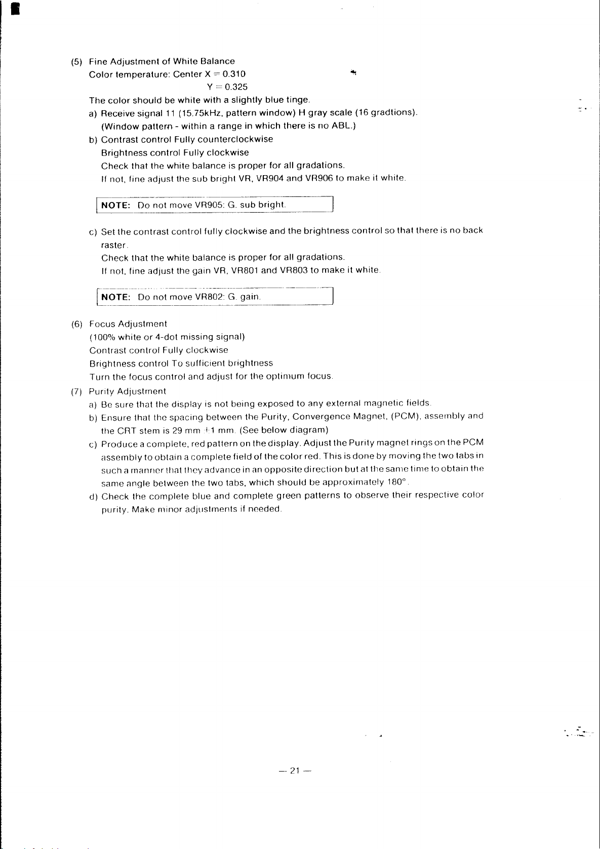
(5)
Fine
Adjustment
Color
The
color
a)
Receive
(Window
b)
Contrast
Brightness
Check
If
not,
c)
Set
raster.
Check
If
not,
of
White
temperature:
should
signal
pattern -within a range
control
that
fine
the
contrast
that
fine
be
11
control
the
white
adjust
the
white
adjust
Center
white
(15.75kHz,
Fully
the
control
tile
Balance
X = 0.310
Y = 0.325
with a slightly
pattern
counterclockwise
Fully
clockwise
balance
sub
balance
gain
is
bright
fully
clockwise
is
VR, VR801
blue
window) H gray
in
which
proper
proper
for
VR, VR904
and
for
and
tinge.
there
all
gradations.
and
the
all
gradations.
VR803
scale
is
no
ABL.)
VR906
brightness
to
to
make
(16
make
control
it
white.
gradtions).
it
white.
so
that
there
is
no
back
(6)
Focus
Adjustment
(100%
white
Contrast
Brightness
Turn
the
(7)
Purity
Adjustment
a)
Be
sure
b)
Ensure
the
CRT
c)
Produce a complete,
assembly
such a manner
same
d)
Check
purity.
or
4-dot
control
focus
<Ingle
Make
Fully
control
control
that
the
that
the
stem
is 29
to
obtain a complete
between
the
complete
minor
missing
clockwise
To
sufficient
and
display
spaCing
mm11
red
that
they
adjustments
adjust
is
between
pattern
advance
the
two
blue
signal)
brightness
not
being
mm.
field
tabs,
and
complete
for
the
the
(See
on
in
which
if
needed.
optimum
exposed
Purity,
below
the
display.
of
the
an
opposite
focus.
to
any
Convergence
diagram)
Adjust
color
red.
direction
should
green
be
patterns
external
the
This
approximately
Magnet,
Purity
is
done
but
at
to
observe
magnetic
the
(PCM),
magnet
by
moving
same
180
their
fields.
assembly
rings
the
time
0
.
respective
on
two
to
the
tabs
obtain
and
PCM
in
the
color
.-
-
21-

•
Purity
4-pole
6-pole
Purity,
Convergence Magnet Assembly
Magnets
magnets
magnets
29' 1 nlln
(Red
(Green
to\lue
to
Magenta
(I'CM)
Convergence)
Convergence)
~t
--,
Il
___
~
I<
Red
to
Blue
(Magenta)
Convergence
(8)
a)
Produce a magenta
b)
Adjust
Also
c)
Vertical
4-pole
d)
Horizontal
angle
e)
Produce a white
f)
Vertical
of
the
g)
Horizontal
keeping
B R
Perform
the
an~le
~
_L_
1-
:
Perform
rot.ltion
Convergence
Adjustment
the
focus
adjust
the
red
and
magnets
red
between
green
6-pole
magnets.
green
the
angle
the
adjustment
betwecn
I·
the
adjustment
of
thc
two
crosshatch
for
the
brightness
blue
lines
on
the
and
blue
them
constant.
crosshatcll
and
magenta
and
between
the
tabs.
by
tabs.
best
overall
to
the
are
converged
PCM
assembly.
lines
are
pattern
lines
magenta
them
by
opening
synchrunous
on
the
focus
desired
converged
on
are
converged
lines
constant.
Green
display.
on
condition.
by
(See
the
display.
are
converged
B/RG
-+-
___
1
Perform
the
angle
~
~lLR
Perform
rotation
. .
the
adJustment
between
I
the
adjustmenl
of
the
two
the
tabs.
'--------~
to
Magenta Convergence
(White)
the
display.
varying
above
by
the
diagrams)
varying
by
varying
angle
the
by
between
two
tabs
the
angle
varying
the
together.
between
the
two
two
keeping
the
tabs
tabs
by
openln~
tabs.
hy
\yndlrollou')
of
the
the
two
tabs
together.
-22-
.-
•
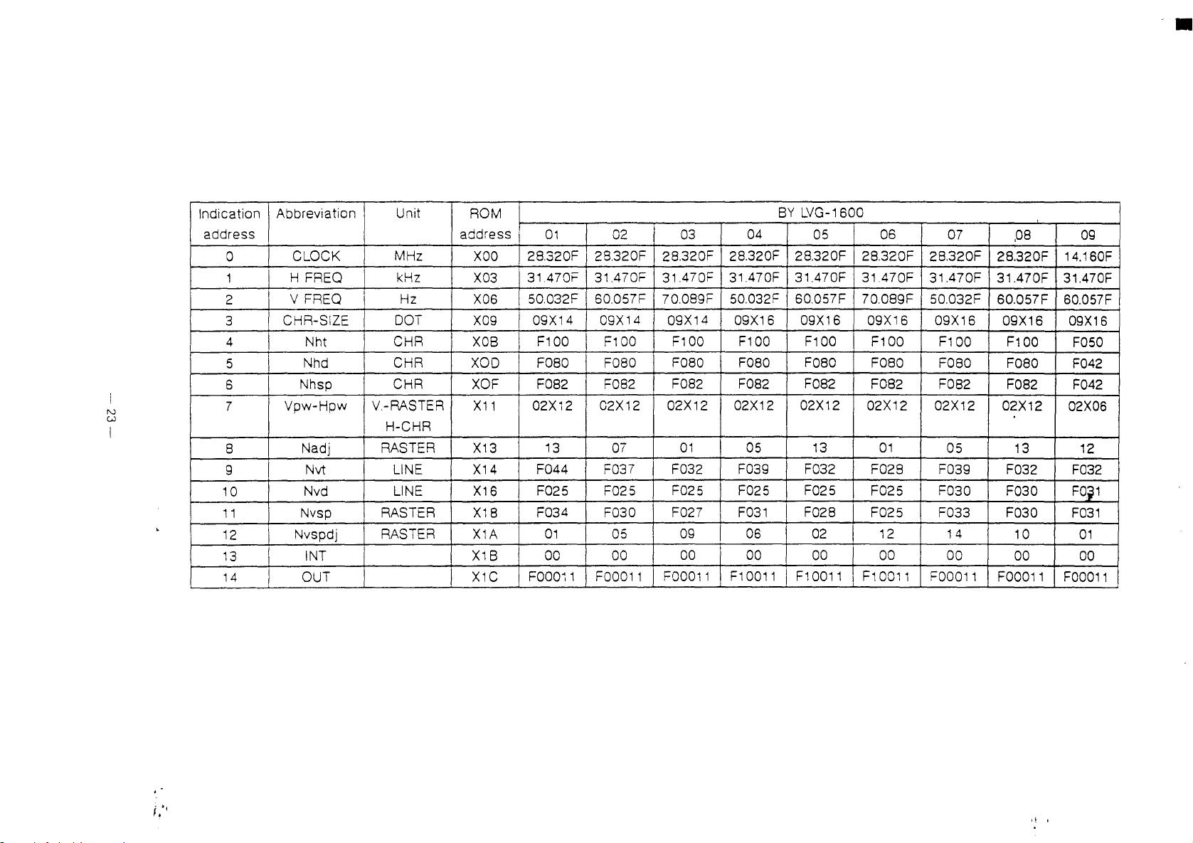
BY
Indication
address
0
1
2
3
4
5
6
N
W
7
S
9
10
11
12
13
14
Abbreviation
CLOCK
H
FREO
V
FREO
CHR-SIZE
Nht
I
Nhd
Nhsp
Vpw-Hpw
Nadj
Nvt
Nvd
Nvsp
Nvspdj
INT
OUT
Unit
MHz
kHz
Hz
~OT
CHR
CHR
CHR
V.-RASTER
H-CHR
RASTER
LINE
LINE
RASTER
RASTER
ROM
address
XOO
X03
X06
X09
XOB
XOO
XOF
X11
X13
X14
X1S
X1S
X1A
X1B
X1C
01
I
28.320F 28.320F 28.320F
31.470F 31.470F 31.470F
50.032F
09X14 09X14
F100 F100 F100
F080
FOS2
02X12
13
F044 F037
F025 F025
F034 F030 F027
01
00 00
FOOOi1
02
SO.057F
F080 F080
F082
02X12 02X12
07
05
FOO011
03
70.0S9F
09X14
F082
01
F032
F025
09
00
FOO011
04
28.320F 2S.320F 28.320F
31.470F
50.032F 60.057F 70.089F
09X16
F100 F100
F080
F082
02X12
05
F039
F025
F031
06
00
F10011
LVG-1S00
05
31.470F 31,470F
09X16
FOSO
F082
02X12
13
F032
F025
F028 F025
02
00
F10011 F10011
OS
09X1S
F100 F100
F080
F082 F082
02X12
01
F028 F039
F025 F030
12
I
00
07
28.320F 2S.320F 14.160F
31.470F
50.032F
09X16
FOeO
02X12 02X12
05
F033 F030
14
00
FOO011
,08
31.470F 31.470F
SO.057F
09X16
F100
FOeO
FOS2
13
F032
F030
10
00
FOO011
09
60.057F
09X16
F050
F042
F042
02X06
12
F032
FOi1
F031
01
00
FOO011
I!
I
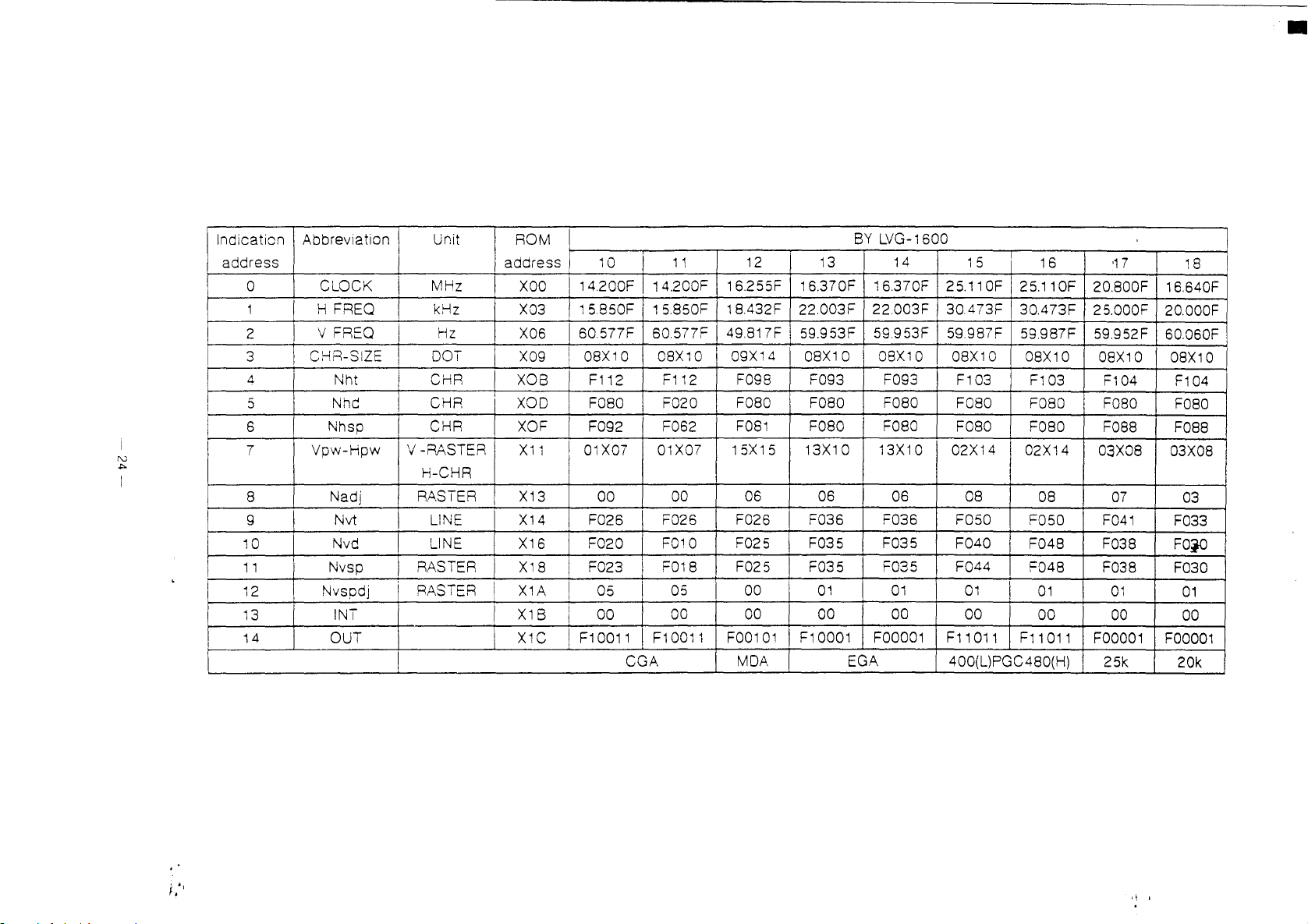
Indication
address
0
1
2
3
I
4
5
I
6
I
7
8
9
10
11
12
13
14
Abbreviation
CLOCK
FREQ
H
FREQ
V
CHR-SIZE
Nht
Nhc
Nhsp
Vpw-Hpw
Nadj
Nvt
Nvd
Nvsp
Nvspdj
INT
OUT
Unit
I
I
MHz
I
kHz
Hz
I
DOT
CHR
I
CHR
I
CHR
V-RASTER
H-CHR
RASIER
LINE
LINE
RASTER
RASTER
i
ROM
address
XOO
X03
X06
X09
XOB
XOO
XOF
X11
X13
X14
X16
X18
X1A
X1S
XIC
10
14.200F 14.200F
15.850F 15.850F 18A32F 22.003F
I 60.577F
08X10
F112
F080
F092 F062
I
01
X07
00
F026 F026 F026
F020
F023
05
I
00
F10011
11
60.577F
08X10
F112
F020
01X07
00 06 06
FOlD
F018 F025 F035 F035
05
00
F10011
CGA
12
16.255F 16.370F 16.370F
49.817F
09X14 I 08X10 08X10
F098 F093 F093 F103
F080
F081
1
5X1
5
F025
00
00
FOO101
MOA
13
59.953F
F080
F080 F080
13X10 13X10 02X14
F036 F036
F035 F035 F040
I
01
00
F10001
BY
LVG-1600
14
22003F
59.953F 59.987F
F080
06
01
00
FOOOO1
EGA
15
25.110F 25.110F
30.473F
08X10
F080
F080
08
F050
F044
01
00
F11011
400(L)PGC480(H)
16
30.473F
59.987F
08X10
F103
F080 F080
F080 F088
02X14
08
F050
F048 F038
F048
01
00
F11011
'17
20.800F
25.000F
59.952F
08X10
F104
03X08
07
F041
F038
01
00
FOOO01
25k
•
18
16.640F
20.000F
60.060F
08X10
F104
F080
F088
03X08
03
F033
FOjO
F030
01
00
FOOO01
20k
1\ i
•
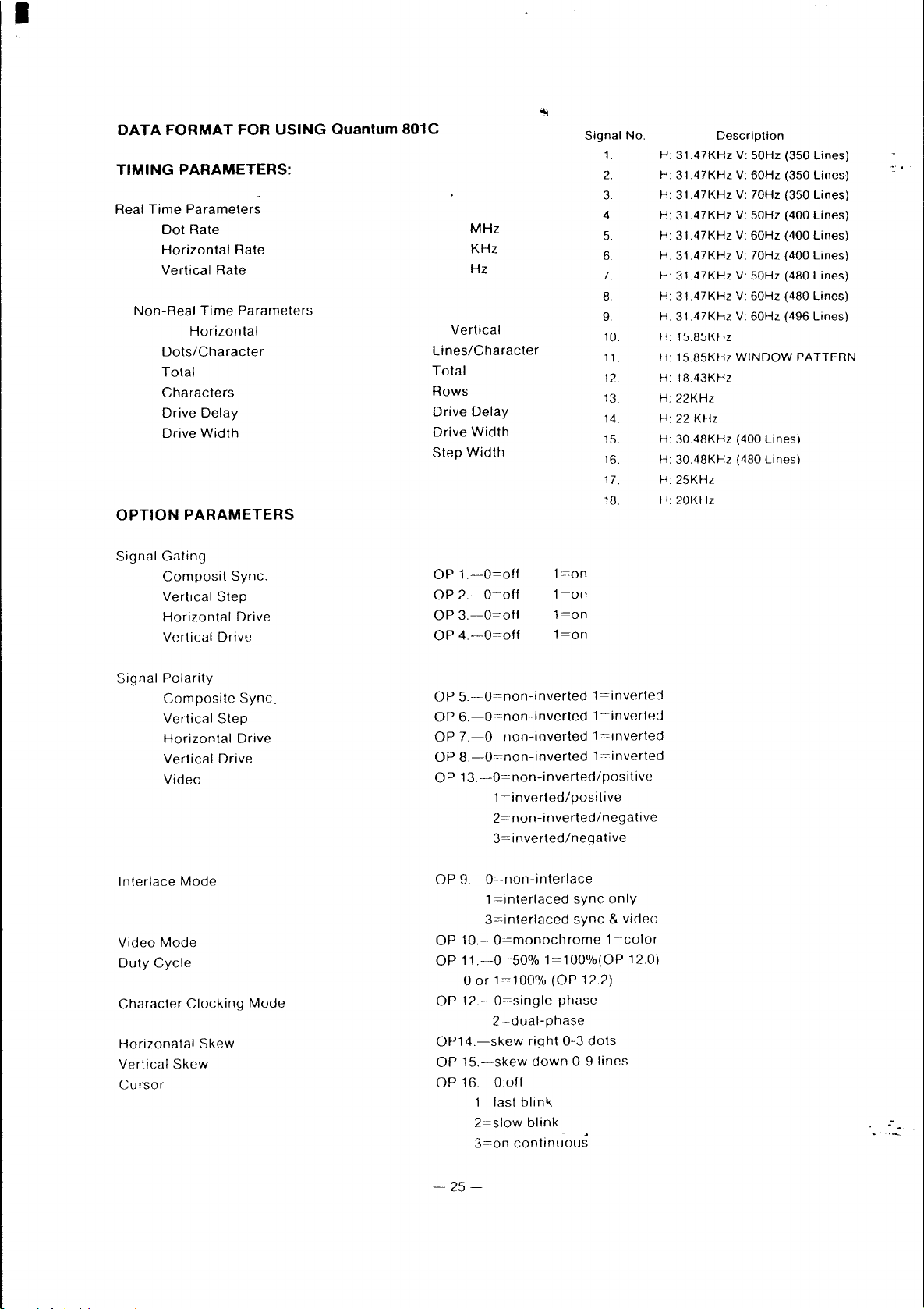
DATA
TIMING
Real
Time
Dot
Horizontal
Vertical
Non-Real
Dots/Character
Total
Characters
Drive
Drive
OPTION
Signal
Gating
Composit
Vertical
Horizontal
Vertical
FORMAT
FOR
PARAMETERS:
Parameters
Rate
Rate
Rate
Time
Parameters
Horizontal
Delay
Width
PARAMETERS
Sync.
Step
Drive
Drive
USING
Quantum
801C
Vertical
Lines/Character
Total
Rows
Drive
Drive
Step
OP
1.-0=off
OP
2.-0=off
OP
3.-0=off
OP
4.-0=off
MHz
KHz
Hz
Delay
Width
Width
l=on
l=on
l=on
l=on
Signal
1.
2.
3.
4.
5.
6.
7.
8.
9.
10.
11.
12.
13.
14.
15.
16.
17.
18.
No.
H:
31.47KHz
31.47KHz
H:
H:
31.47KHz
31.47KHz
H:
31.47KHz
H:
31.47KHz
H:
H
31.47KHz
H:
31.47KHz
31.47KHz
H:
H:
lS.8SKHz
1S.8SKHz
H:
l8.43KHz
H:
H:
22KHz
22
H
30.48KHz
H:
H
30.48KHz
H:
25KHz
H:
20KHz
Description
KHz
V:
50Hz (350
V:
60Hz (350
V:
70Hz
(350
V:
50Hz
(400
V:
60Hz (400
V:
70Hz
(400
V:
50Hz
(480
60Hz (480
V:
V:
60Hz (496 Lines)
WINDOW
(400
(480
PATTERN
Lines)
Lines)
lines)
lines)
lines)
lines)
lines)
Lines)
Lines)
Lines)
-
Signal
Polarity
Composite
Vertical
Horizontal
Vertical
Video
Interlace
Video
Mode
Duty
Cycle
Character
Horizonatal
Vertical
Cursor
Skew
Step
Drive
Mode
Clocking
Skew
Sync.
Drive
Mode
OP
5.-0=non-inverted
OP
6.
-O=non-inverted 1 =inverted
OP
7.-0=non-inverted 1 =inverted
OP
8.-0=non-inverted
OP
13.-0=non-inverted/positive
1
=inverted/positive
2=non-inverted/negative
3=inverted/negative
OP
9.-0c-cnon-interlace
1
=interlaced
3=interlaced
OP
1O.-0~-=monochrome
OP
11.-0=50%
o
or
1~100%
OP
12-0~single-phase
2=dual-phase
OP14.-skew
OP
15.-skew
OP
16.
-O:off
1=last
2=slow
3=on
1=100%(OP
right
down
blink
blink
continuous
l=inverted
1-c-inverted
sync
sync & video
(OP
12.2)
0-3
dots
0-9
lines
only
1
=-~color
120)
.-
-25-
 Loading...