

NEC J6N Service Manual

J6N Service Guide
NEC Computers APAC Page 1
J6N Disassembly
• Required Tools
• Disassembly Instructions
• DIP Switch setting
• Reassembly Instructions

J6N Service Guide
NEC Computers APAC Page 2
Required Tools
All J6N maintenance procedures can be performed using the following tools:
n Tweezers
n Small Philips screwdriver
n Small Flat screwdriver
n Spacer screwdriver Ø 5MM

J6N Service Guide
NEC Computers APAC Page 3
Disassembly Instructions
This document contains step-by-step disassembly instructions for the J6N. The
instructions are clarified by images of the part that is being removed or disassembled.
Furthermore, the screws that are removed are shown next to the image of the parts
themselves.
When disassembling the system unit, follow these general rules.
§ Do not disassemble the system into parts that are smaller than those specified in the
instructions.
§ Label all removed connectors. Note wh ere the connector goes and in what position it
was installed.
§ Turn off the power and disconnect all power and all options. Also remove any PCCards cards that are in the PCMCIA slot.
J6N Service Guide
NEC Computers APAC Page 4
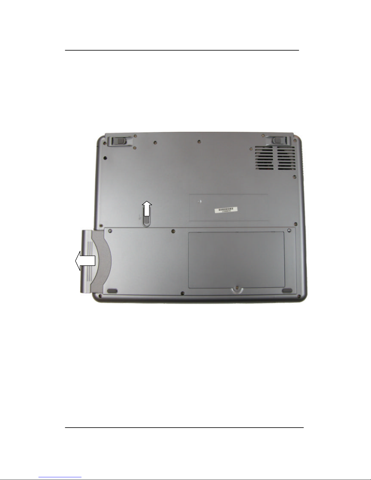
1. Battery
Remove the battery pack of the notebook as follows:
a. Close LCD panel.
b. Flip over the unit.
c. Push and hold battery lock.
d. Pull outward to remove the battery.
Fig. 1: Remove Batter y.
J6N Service Guide
NEC Computers APAC Page 5
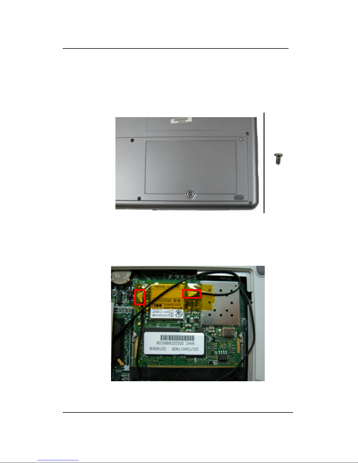
2. Memory / Wireless module
a. Unscrew one screw to open SO-DIMM / Mini PCI Slot cover.
b. Release the SO -DIMM memory module(s).
c. Remove the m emory module(s).
Fig. 2: SO-DIMM / Mini PCI Slot Cover .
d. Disconnect two antenna connections on wireless module.
e. Release and remove the wireless module from Mini PCI slot.
Fig. 3: Wireless Module.
J6N Service Guide
NEC Computers APAC Page 6
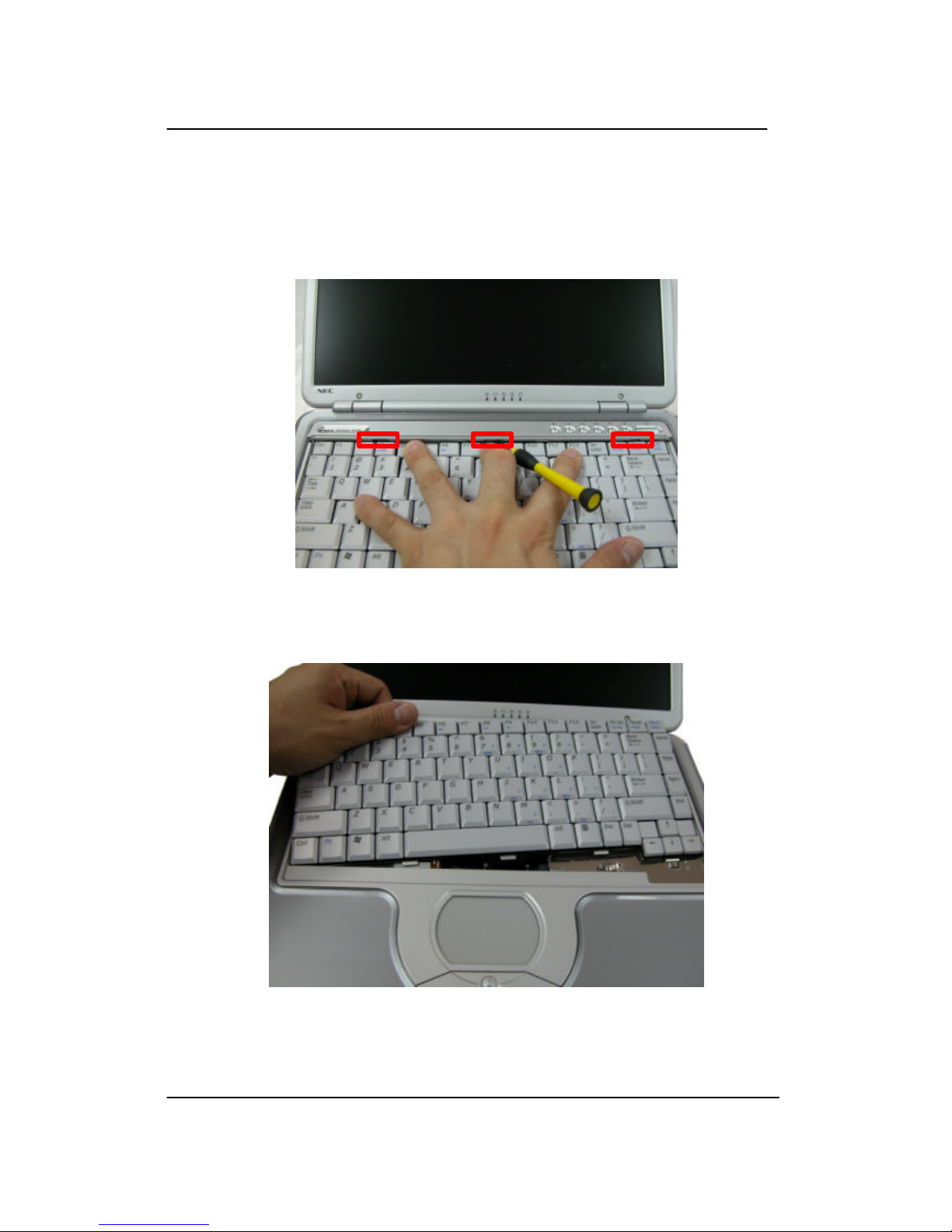
3. Keyboard Cover / Keyboard
a. With help small flat screw driver, carefully lift up the keyboard cover .
Fig. 4: Keyboard Cover
b. Lift up the keyboard.
Fig. 5: Keyboard
J6N Service Guide
NEC Computers APAC Page 7
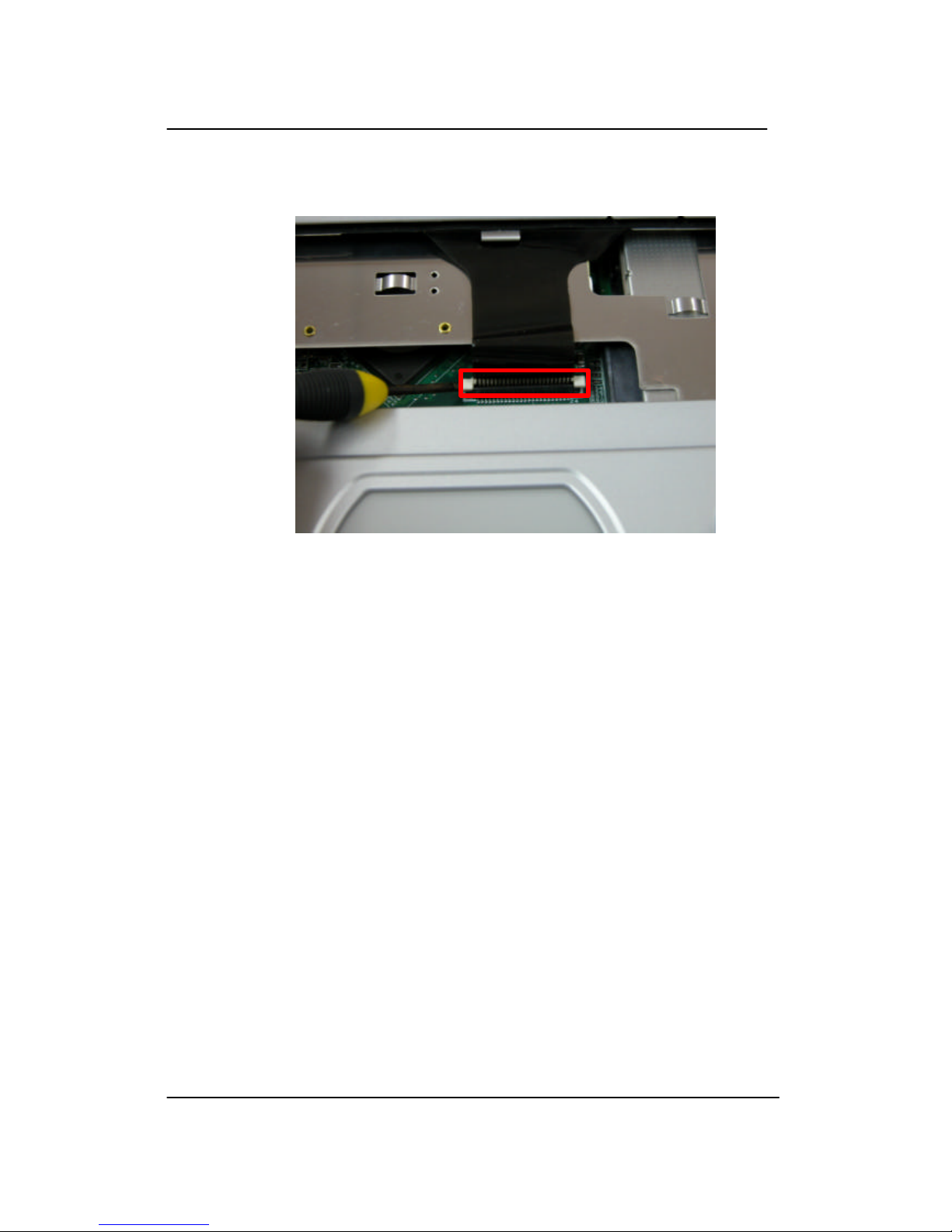
c. Unlock the keyboard flat cable connector.
Fig. 6: Keyboard cable connector
 Loading...