

Page 1
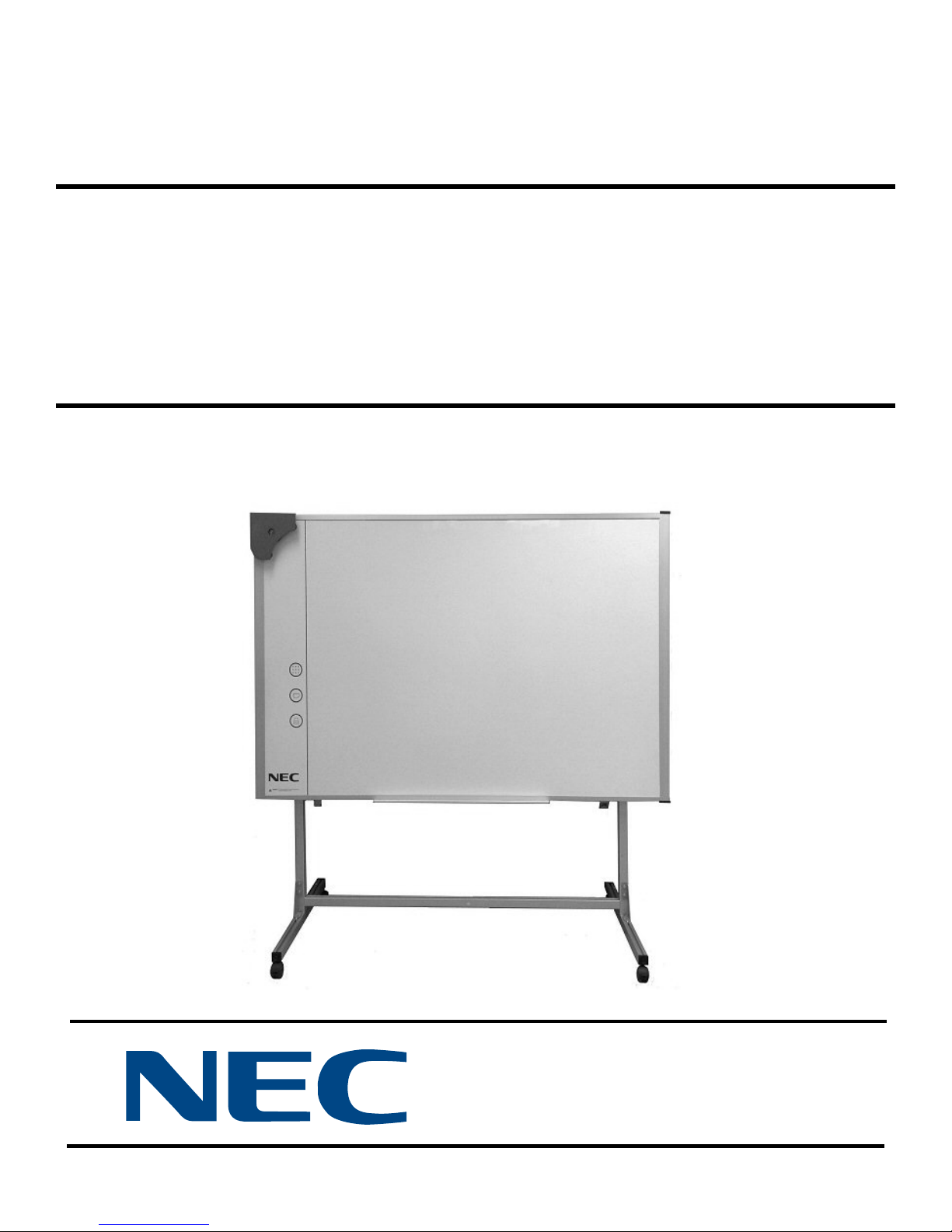
ASSEMBLY INSTRUCTIONS
Mobile Whiteboard
Stand
IWSTAND
Copyright © 2007, NEC Display Solutions of America. All Rights Reserved
Made in USA
Page 2
IWSTAND Assembly Instructions
Thank you for choosing the IW STAND for your NEC Interactive WhiteBoard.
SAFETY INFORMATION
Please read, understand, and follow all safety information contained in these instructions prior to the
use of this Mobile Whiteboard Stand.
Retain these instructions for future reference.
Intended Use:
The IWSTAND was intended for indoor use with the IW77 Interactive Whiteboard only. Use outdoors or on an unstable
or unlevel floor is not recommended and could create a potentially unsafe operating condition.
Use of replacement parts, or installation instructions other than described in this manual has not been evaluated by NEC
and may lead to an unsafe condition.
This stand is not intended for use by unsupervised children.
Explanation of Signal Words and Symbols in Safety Labels and Instructions
WARNING: Indicates a potentially hazardous situation, which if not avoided,
could result in death or serious injury.
CAUTION: Indicates a potentially hazardous situation, which if not avoided,
may result in minor or moderate injury.
Risk from muscular strain
WARNING
To reduce the risk associated with muscle strain and/or pinch:
- Use care when lifting and placing the
- This product is intended to be used with the NEC
- Before using, make sure that all the wheels are in the locked position.
- Use care when placing the Whiteboard on the Floor Stand to prevent
pinching of hand or fingers between mating parts.
To reduce the risk associated with impact or falling:
IW77 Interactive Whiteboard on the Stand.
Interactive White Board only.
- Always provide proper adult supervision when using this
- Do not allow children to stand or hang on to any part of this product.
NEC is a registered trademark of NEC Corporation
2 © NEC Display Solutions of America, All Rights Reserved, 2007
Floor Stand around children.
Page 3
IWSTAND Assembly Instructions
The IWSTAND is designed to hold the NEC IW77
Interactive Whiteboard.
Before you attach your board to the
stand, please review these important instructions.
The following instructions will guide you through the steps for assembly.
Estimated assembly time is 15 minutes.
If you require assistance or are missing parts, contact NEC by email at
http://www.necdisplay.com/SupportCenter
Required tools are: Hex key (5mm supplied)
Adjustable or Open end wrench (13 mm not supplied)
Philips Head screwdriver (not supplied)
It is important to layout parts prior to beginning assembly.
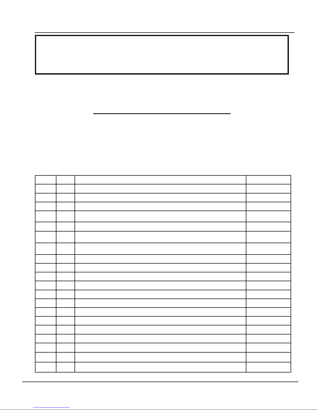
Parts List
Item Qty Description Color Dot
1 1
Hanger Bracket
2 1 Right vertical sliding assembly Black
3 1 Left vertical sliding assembly Light Blue
4 1
5 1
6 1
Frame Extrusion; lower stationary horizontal member Red
Frame Extrusion; lower moving horizontal member Orange
Frame Extrusion; top moving horizontal member Dark Blue
7 2 Frame Extrusion; leg Yellow
8 2 Left Support Bracket
9 2 Right Support Bracket
10 2 “U” Bracket (bottom mounting bracket from NEC IW77 )
11 4
Button Head Socket Screw; M8 x 20 ( 3/4" L)
12 4 Philips Head Machine Screw; M6 x 35 ( 1 1/8" L)
13 2 Philips Head Machine Screw; M4 x 10 ( 3/8" L)
14 8 Hex Head Cap Screw; M8 x 60 ( 2 3/8" L)
15 8 Washer; M8 - 24mm OD ( 1" OD)
16 4 Lock Nut; M8 thread
17 4 Locking caster; 3/8-16 shank
18 6 End Cap; black
19 6 Fastener; black
20 2 Bracket, Lower Board
© NEC Display Solutions of America. All Rights Reserved, 2007 3
Page 4
IWSTAND Assembly Instructions
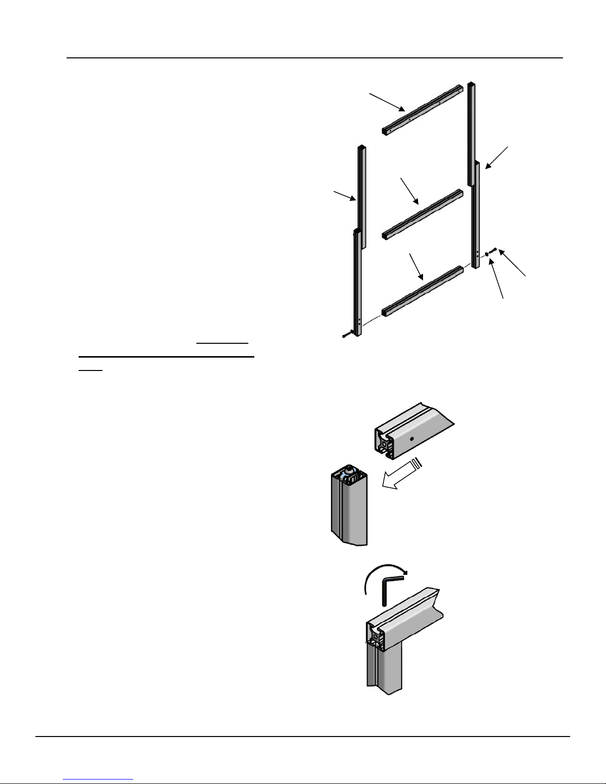
Frame Assembly
The first step in the assembly process is
to identify and place all the frame members on the floor as shown.
Please note that all of the frame members have been color coded for easy
identification. See Parts List for color
code and identification numbers. A
Color Dot has been placed on the surface that is considered the front of the
stand or relating to special assembly
procedure in these instructions.
The details pertaining to how the frame
members fit together is illustrated in
Detail A. Always slide the rail slot into
the retaining clip as shown.
Frame member 5 and 6 have access
holes located in the slot. Make sure
that the hole lines up with the screw
head. You will be able to see the screw
head by looking through the access
hole. When the two are aligned, place
hex key (allen wrench) into hole and
tighten screw.
Assemble as shown: first assembling
lower moving frame rail ( 5 - Orange )
and then upper moving frame rail (6 -
Dark Blue ) to sliding frame verticals (2
- Black and 3 - Light Blue). The pull
pins are on the back side. Also, note
that the lower moving frame rail ( 5 )
has two large holes on one side. This
is the backside. The upper rail ( 6 )
has four holes on one side. This is the
front side of the rail. Attach this rail
second, positioned as shown.
Finally attaching the lower horizontal
member ( 4 - Red ) to frame verticals
( 2 and 3 ) with a screw ( 14 ) and
6
3
5
2
4
14
15
Detail A
4 © NEC Display Solutions of America. All Rights Reserved, 2007
Page 5
IWSTAND Assembly Instructions
Mounting Rail Attachment
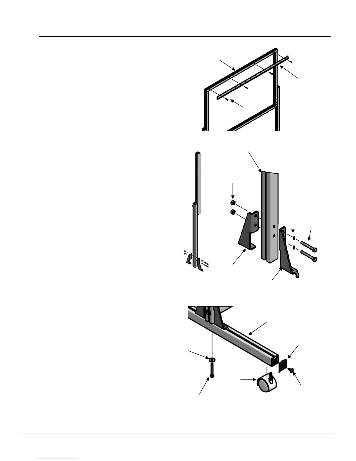
Using a Philips screwdriver attach the board
mounting rail (1) as shown to top rail ( 6 ) with
four Philips head machine screws ( 12 ).
Support Bracket Attachment
There are two support brackets ( 8, 9 )for
each vertical frame member. Attach brackets
with the flat side facing toward the outside of
the frame as shown.
Insert the hex head screw (14 ) from the front
side of support bracket, through the washer
(15 ) then the extrusion and through the other
support bracket. Place locknut (16) onto
screw. Finger tighten only, do not fully
tighten at this time.
Repeat for other vertical frame member.
6
1
12
2, 3
16
15
14
8
Leg Attachment
Screw casters (17 ) into leg extrusion ( 7 Yellow). Caster will only screw in from one
side. The affixed Yellow Dots will be on the
outside of the frame. Use pliers or wrench to
tighten.
Take leg extrusion and place into the leg sup-
15
ports as shown. Center hole of leg extrusion
should line up with center of vertical frame
member.
Attach leg with washer (15 ) and hex head
17
screw (14 ). After screw is tight, tighten the
two support bracket screws.
Attach end cap (18 )with fastener(19 )to each
14
end of leg extrusion and top horizontal rail.
© NEC Display Solutions of America. All Rights Reserved, 2007 5
9
7
18
19
Page 6
IWSTAND Assembly Instructions
Whiteboard Attachment
After both legs are attached to frame, place
into the upright position.
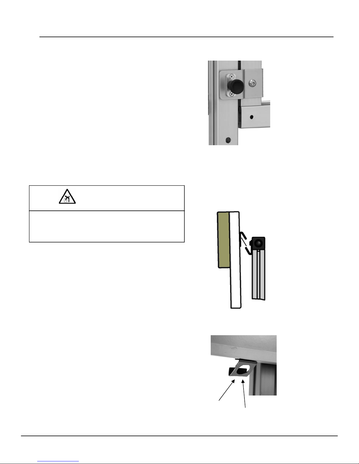
The upper sliding frame has two release pins
( Detail B ) for height adjustment. Two people are required to make any height adjustments.
There are three different heights available.
The lowest hole on the frame is to be used
when moving the Whiteboard.
Detail B
To raise frame, grasp the horizontal rail ( 6 ),
pull out release pin, and lift up to the desired
height. Release pin when you have reached
the desired height. Pin will drop into hole.
WARNING
To reduce the risk associated with muscle strain:
• Always use more than one person when installing
or removing the Whiteboard
You are now ready to attach the Whiteboard.
With one person holding each side of the
board, carefully lift it into position so that the
bracket lip is above the hanger bracket on the
stand. Now lower onto the stand hanger
bracket. Make sure that the board is securely
in place before releasing
( Detail C ).
Locate the two “U” shaped brackets (10)
supplied with the NEC Whiteboard. Looking
at the underside of the bottom rail locate the
small Philips head machine screw, remove it
and (13) install bracket to the bottom edge
with the “circle” opening facing the front of
the board. Repeat for the other bracket.
Detail C
6 © NEC Display Solutions of America. All Rights Reserved, 2007.
10
13
Page 7
IWSTAND Assembly Instructions
5
IW77 Whiteboard Bracket Attachment
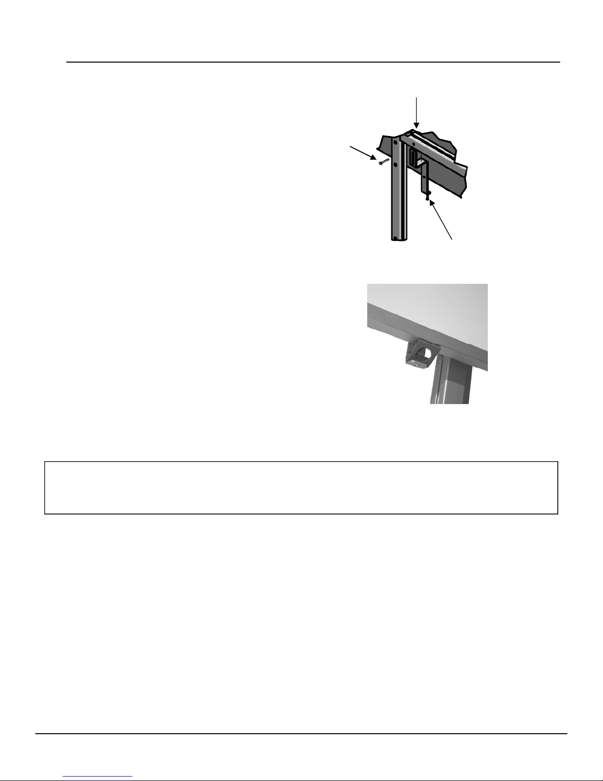
For a secure attachment to the IWSTAND, install
mounting bracket (20) to the lower horizontal frame
member (5) as shown.
Using the hex key, loosely attach the bracket (20) to
frame member with a (11) M8x20 screw. Move
bracket up until it touches the “U” bracket just attached to bottom side of board. Attach “U” bracket
to the mounting bracket. Now tighten (11) M8
screw.
Connections
You are now ready to start using the your Interactive
Whiteboard. Please follow the directions that came with
the IW77 Board for connections and instructions for
usage.
11
20
Caution
In the travel position the IWSTAND Stand is quite stable for movement. For safe transport across rough
surfaces or ramps and inclines, the user should request the assistance of a second person.
© NEC Display Solutions of America. All Rights Reserved, 2007.
Page 8

Warranty
NEC warrants to the original purchaser that its stands are free from defect in
material and workmanship. While it is expected that you will be extremely
pleased with the quality of your new NEC product, in the unlikely event that
you have a problem caused by defects in materials or workmanship, NEC will
repair or replace the defective stand at its option and expense.
IWSTAND components are covered by a 1-year limited warranty.
This warranty does not cover repairs due to neglect, abuse or misuse of the stand
by purchaser, or when used for rentals.
It is important to note that our warranty is not an unconditional warranty for the
life of the product. Although NEC uses high quality components, materials do
eventually wear out with normal use. Like any other products, NEC stands are
not
indestructible. Therefore, our warranty excludes normal wear and tear
(moving parts and wheels), damage caused by accident, abuse, misuse, improper
care, or alteration.
This warranty gives you specific legal rights, and you may also have other
rights that vary from state to state. Some states do not allow limitations on implied warranties and / or do not allow the exclusion of incidental or consequential damages, so the above limitations and exclusions may not apply to you.
For additional information about NEC products or for additional contact information, visit our website at www.necdis play.com
8 © NEC Display Solutions of America. All Rights Reserved, 2007
 Loading...