

Page 1

N
E
C
I
T
3
5
1
0
/
I
T
2
5
1
0
O
P
E
R
A
T
I
O
N
S
M
A
N
U
A
L
Issue 1
Page 2

Page 3
Operations Manual
NEC America, Inc.
Document Solutions
CC49001
Issue 1
NEC IT3510/IT2510
Page 4

Page 5

Conten ts of this ma nual are subject to c hange w ithout prior n otice at t he discre tion of
NEC America, Inc. This docum ent h as be en prep ared for th e use of e mploy ees a nd
customers of NEC America, Inc. and may not be reproduced without prior written
approval of NEC America, Inc.
Window s is a registered trademark of M ic ros oft Corporation.
Copyright 2001
NEC America, Inc.
6535 N. State Highway 161
Irvin g , TX 75039-2402
Document Solutions
Page 6

Page 7

NEC IT3510/IT2510 Operations Manual 1
Regulatory and Safety
Information
SECTION 1REGULATORY INFORMATION
The follow ing info rmat ion p rovid es dat a for using t his prod uct on the P ub lic Swit ched
Telephone Network, as required by the Federal Communications Commission (FCC).
1.1 FCC Notifica tion
This product complies with Part 68 of the FCC Rules and Regulations. On the
bottom of this product is a label that contains, among other information, the
FCC Registration number and the Ringer Equivalence Number (REN). If
requested, this information must be provided to the telephone company.
This prod uc t uses the foll ow ing USOC ja cks : RJ11C
The REN i s used to determ ine th e quant ity of d evices th at can be conn ected
to the telephone line. Excessive RENs on the telephone line may result in the
devices not ringing in response to an incoming call. In most, but not all areas,
the sum of the RENs should not exceed five (5.0). To be certain the number of
devices t hat ma y be connec ted to the lin e, as deter mined by the total RENs,
contact th e teleph one co mpany servic ing your area to ensure the REN is not
exceeded.
If this product cau ses harm to the tele phone netw ork, th e t elephone company
will notify you in advance. If advanced notice isn’t p ractical, the telephone
company will notify the customer as soon as possible. Also, you will be
advised of your right to file a complaint with the FCC if you believe it is
necessary.
The telephone company may make changes in its facilities, product,
oper at ions, or pro c edures t hat could a ffec t the operation of this product. If this
happens, the telephone company will provide advance notice in order for you
to make any necessary modifications in order to maintain uninterrupted
service.
If trouble is experien ced with this product, p lease cont act NEC Ame rica, Inc.
1-800-232-9632
for repair and (or) warranty information. If the trouble is
causing har m to th e t elephone net wo rk, the telep ho n e c o m pan y may re qu est
you to remove th e product fro m th e networ k un t il th e probl em is re so lved.
Page 8

2 Regulatory and Safety Info rmati on
Issue 1 NEC IT Series
The following maintenance can be performed by the customer:
Ë
Document Jam
Ë
Print Paper Jam
Ë
Installing Pri nt Pap er
Ë
Replac ing the TX Mark er Stamp
Ë
Others
This product cannot be used on telephone company provided coin-op service.
A connection to party line service is subject to state tariffs.
If a telephone set is to be u sed wi th this pro d u c t, insure t hat it meets FCC Part
68 for Hearin g Aid com p atibi lit y.
When prog ramming an d/or making tes t calls to eme rgency numb ers, please
remember to:
Ë
Remai n on the line a nd briefly exp lain to the dis patcher the r eason for
the call.
Ë
Perform such activities in the off-peak ho urs, such as ea rly morning o r
late evening.
This prod uct generates a nd uses radio frequency ene rgy and if not in stalled
and used properly, that is, in strict accordance with the manufacturer’s
instructions, may cause interference to radio and television reception. It has
been type-tested and found to comply within the limits for a Class A computing
device in accordance with the specifications in subpart J of Part 15 of the FCC
Rules a nd Regula tions. Part 1 5 is desi gned to pr ovide reaso nable pr otection
against such interference in a residential installation. However, there is no
guarantee that interference will not occur in a particular installation. If this
product does cau se int erfe renc e to rad io or tele vi sion rece ption , wh ich can be
determined by turning the product off and on, the user is encouraged to try to
correct the interference by one or more of the following measures:
Ë
Reorient the receivin g antenn a.
Ë
Relocate the facsimile with respect to the receiver.
Ë
Move the facsimile away from the receiver.
Ë
Plug th e fac simile in to a d ifferent p ower outlet so tha t the facsimil e and
the receiver are on different branch circuits.
Page 9

NEC IT Series Issue 1
NEC IT3510/IT2510 Operations Manual 3
1.2 Industry Canada Notification
Certification Number: 140 11281 A
Complies with: CP-01, Issu e 8, Pa rt I
Ringer Equivalence Number: 0.4
Connector: CA 11A
The Industry Canada label identifies certified equipment. The certification
means that the equipment meets certain telecommunications network
protective, operational, and safety requirements. The department does not
guarantee the equipment will operate to the user’s satisfaction.
Before ins talling the equipm ent, users sho uld ensure that it is per missible to
be connec ted to the fac ilities of the lo cal telecom municat ions compa ny. The
equipmen t must also b e instal led usin g an accept able me thod o f con nection.
In some cases, the company’s inside wiring associated with a single line
individual service may be extended by means of a certified connector
assembly (telephone extension cord). The customer should be aware that
complian ce wi th the a bo ve con ditio ns ma y not prev ent degrada tion of servi ce
in some situations.
Repairs to certified equipment should be made by an authorized Canadian
mainten ance facility desig nated by the su pplier. Any repa irs or installations
made by the user to this equipment, or equipment malfunctions, may give the
telecommunications company cause to request that the user disconnect the
equipment.
For their own protection, users should ensure that the electrical ground
connections of the power utility, telephone lines, and internal metallic water
pipe system, if present, are connected together. This protection may be
particula rly im portant in rural areas.
As an
ENERGY STAR® partner, NEC
Corporation has determined that this
product meets the
ENERGY STAR
®
guidelines for energy efficiency.
ENERGY STAR® is a U.S. registered
mark.
Page 10

4 Regulatory and Safety Info rmati on
Issue 1 NEC IT Series
CAUTION 1: Users should not attempt to make such connections
themselves, but should contact the appropriate electrical
inspection authority, or electrician, as appropriate.
CAUTION 2: The act of monitoring or recording telephone
conversations under certain circumstances may violate
federal or state statutes. Consultation with your legal
counsel prior to engaging in such practices would be
advisable.
NOTICE : The Ringer E quivalence N umber (REN) a ssigned to ea ch terminal
device provides an indication of the maximum number of terminals allowed to
be connec ted to a tele phone inte rface. The t ermination o n an interf ace may
consist of any combination of devices, subject only to the requirement that the
sum of th e R EN s of all the devices does no t ex c eed fiv e (5.0).
Safety Certifications
This equipment has been listed by Underwriters Laboratories and found to
comply with all the applicable requirements of the standard for telephone
equipment U.L. 1950.
This equipment complies with CSA standard C22. 2 N o . 225.
1.3 Laser Classifi c at ion and Safet y
Ë
Laser Safety
This product is certified as a Class 1 laser product under the U.S.
Department of Health and Human Services (DHHS) radiation
performance standard, according to the Radiation Control For Health
And Safety Act of 1968. This means that this product does not produce
hazardous laser radiation.
Since radiation emitted inside this product is completely contained within
protective housings and external covers, the laser beam cannot escape
from the mach ine du ring any p hase of us er ope ratio n.
Ë
Internal Laser Radiation
Product
Maximum Radiation
Power
Wavelength
IT3510 27.8 uW 775 nm to 795 nm
IT2510 19.5 uW 770 nm to 795 nm
Page 11
NEC IT Series Issue 1
NEC IT3510/IT2510 Operations Manual 5
This is a Class IIIB laser diode assembly that has a visually invisible
laser bea m. The print head as sembly (laser) is n ot a fiel d service item;
therefo re, th e pr in t head should not be opened under any circumstance.
Ë
Classifi cation of th e L as er P roduct
This product is classified as a Class 1 laser product under the CDRH
regula tio ns of t he USA.
1.4 CDRH Regulations
The Center for Devices and Radiological Health (CDRH) of the U.S. Food and
Drug Administration implemented regulations for laser products on August 2,
1976. These regulations apply to laser products manufactured from August 1,
1976. Compli ance is mandato ry for products marke ted in the United States .
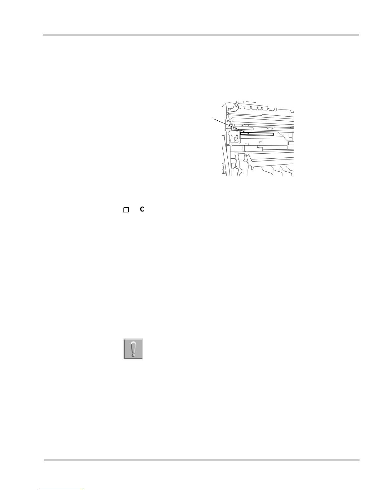
The label shown in the following illustration indicates compliance with the
CDRH regulations and must be attached to laser products marketed in the
United States.
Laser access window
When the side cover is opened and the imaging unit is removed
.
Use of controls, adjustments, or performance of
procedures other than those specified in this manual
may result in hazardous radiation exposure.
Page 12

6 Regulatory and Safety Info rmati on
Issue 1 NEC IT Series
1.5 Transmitter Subscriber’s Identification
As of Dece mber 20, 1992, the Telephone Cons umer Protection A ct of 1991
requires that the f ollowing informati on must be included in the t op marg in of
each page of the facsimile transmission:
Ë
The date and time the facsimile was sent.
Ë
The name of the business or company.
Ë
The fac s imil e telephone numbe r of the sendi ng ma chine .
Ë
It is illegal to turn off the TSI feature.
This facsimile machine meets these requirements by including this information
with in the Trans m i t t er’s St a t io n Iden tif i c ation (TSI ) .
Please refer to Section 1.4 Required Initial Registration/Settings and
Confirma tion in Chapter 3 Re gistration and Setti ng Operations on pag e 3-4,
and Section 2.5 Registering the Transmitter Subscriber’s Identification (TSI) in
Chapter 3 Registration and Setting Operations on page 3-17 for instructions
on programming the TSI and the date and time. It is most important to always
keep the TSI feature turned on when sending a document.
Page 13
NEC IT Series Issue 1
NEC IT3510/IT2510 Operations Manual 7
SECTION 2SAFETY PRECAUTIONS
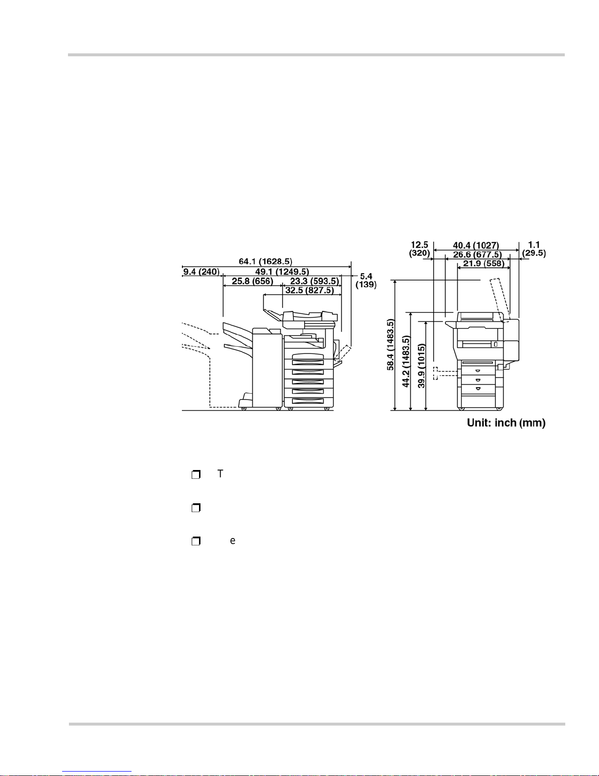
2.1 Installation Space
Sufficient space must be provided to enable normal operation, routine checks,
replacement of consumables, and to perform routine maintenance on the
product.
Ë
There is a ventil at ion duc t on the right-hand side of the unit . A gap of at
least six inches (150 mm) must be maintained.
Ë
A gap of at least 12.2 inches (310 m m) m ust be maintained to the right
of the to unit for toner bottle replacement.
Ë
The figures above represent the dimensions when the optional
assemblies are mounted.
Page 14

8 Regulatory and Safety Info rmati on
Issue 1 NEC IT Series
2.2 Using this Product
The fol lowin g items describe general areas of product usage by the end-user.
Ë
Conditions on Installation and Use
The following list provides safety warnings for properly operating the
machine. Please adhere to these guidelines, as serious injury or
machine failure may occur.
Warnings
Stop usi ng t his p roduc t imme dia tely if smo ke
or an abnormal odor is coming from the unit.
Failure to do so may result in a fire, electric
shock, or product failure. Disconnect the power
plug from the wall outlet immediately, and
contact the dealer for service.
Do not place small metal objects or
containers filled with liquids on top of the
unit. Items suc h as paper clips, chemicals ,
cosmetics, drinking glasses, flower vases,
etc. can harm the machine.
Using the items above may result in fire or
machine damage, if liquids or metal objects drop
into the unit.
Stop using this product immediately if this
product is d ropped or any cover is damaged.
Failure to do so may result in a fire, electric
shock, or product failure. Disconnect the power
plug from the wall outlet immediately, and
contact the dealer for service.
Do not disassemble or remo del this product.
Failure to do so may result in a fire, electric
shock, or product failure. Also, damage t o your
eyesight may occur if the laser is serviced.
Contact the service center or dealer for any
internal checks and repairs a vailable if there are
no appropriate instructions in this manual.
Stop usi ng this product immediately i f water
or any metal object is dropped inside the
product.
Failure to do so may result in a fire, electric
shock, or product failure. Disconnect the power
plug from the wall outlet immediately, and
contact the dealer for service.
Take care not to damage the power cord in
any m ann e r. Do no t tw ist , he at , for c ibly pu ll ,
or place heavy objects on this cord.
Such action may result in a fire or electric shock.
Do not unplug the power cord with wet
hands.
Such action may result in a n electric shock due
to electrical discharge.
High voltage is used inside this product. Do
not remove any of the covers.
Such action may result in electric shock.
This is a warning that indicates a hazard that can lead to
serious injury or death.
Page 15

NEC IT Series Issue 1
NEC IT3510/IT2510 Operations Manual 9
Do not operate the product or install any
machine options during a thunderstorm.
Such actions m ay result in an electric shock or
product failure.
Do not touch the toner fixing unit located
inside the machine, or the area around it, as
it becomes extremely hot.
Some areas are hot enough to cause serious
burn injury.
Cautions
Do not place the prod uct in direct sunlight or
near a heater.
Such an environment may c ause product failure
or even a fire due to extreme temperatures
inside the machine chassis.
Do not place the product on an uneven
surface, or somewhere that is subject to
vibration or mechanical instability.
Such an environment may cause injury or failure
if the product falls dow n or tips over.
Do not place the product in a humid, dusty,
smoky, or steamy environment.
Such an environment may c ause product failure
or poor performance in the scanning and printing
mechanisms.
The ground cabl e must be connected.
In certain cases, a ground cable should be
connected to an independent earth ground. Do
not connect the ground to a gas pipe, lightning
rod, water pipe, or a telephone ground.
Do not cover the ventilation grille on the
product.
If this grille is blocked or covered, internal
temperature will rise and may cause product
failure.
Hold the solid plug when disconnecting the
power cord.
The power cord should be disconnected by
holding and pulling on the solid plug part and not
on the cord itself. Pulling on the cord may cause
power cord damage, resulting in a fire or electric
shock.
Warnings
This is a caut ion th at indica tes a hazar d that c an lea d to in jury o r
damage to property
.
Page 16
10 Regulatory and Safety Information
Issue 1 NEC IT Series
Care must be taken not to catch your fingers
or clothes when closing the cover.
Some surfaces are sharp or pointed, which may
result in injury to person or clothing.
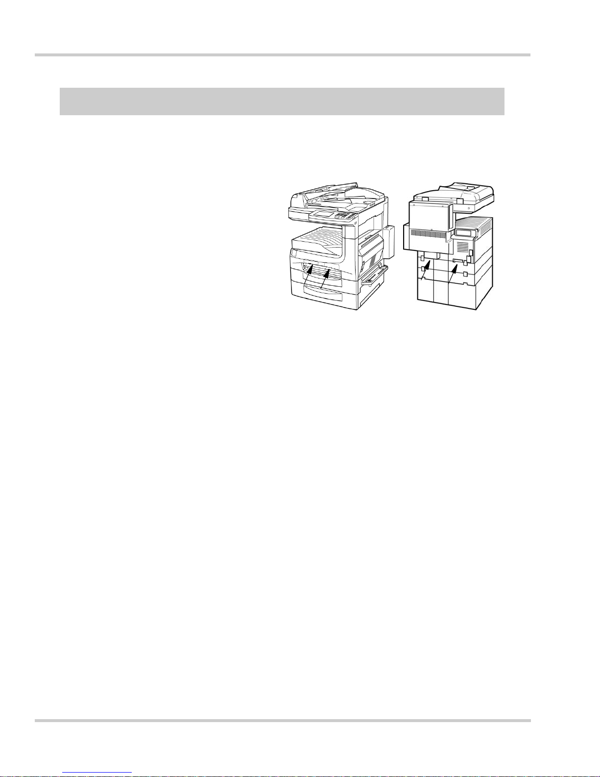
Lift the product in the positions indicated
when transporting the product.
Lifting the product using any other area may
result in injury to person or product damage.
Before moving the product, first disconnect
the power cord and telephone/facsimile line
connection.
Failure to do so may damage the power cord
and line cable.
Do not place the power cord near a heater.
This may cause the power cord to melt, thus
exposing internal wiring that can cause fire or an
electric shock.
Do not touch the inside of the side cover or
the copper terminals located at the lower part
of the imaging unit.
Doing so may result in product failure due to
static discharge.
For product and property safety reasons,
disconnect the power cord from the wall
outlet when this product is not to be used for
prolonged periods.
Doing so will avoid the possibility of fire or
product failure.
Cautions
Page 17

NEC IT Series Issue 1
NEC IT3510/IT2510 Operations Manual 11
Recommendations
Do not place the product in an excessively
hot (over 87 degrees F) or cold (less than 27
degrees F) environmen t.
Doing so may resu lt in erratic operation.
Do not place the product in a location where
chemical vapors are emitted.
Doing so may damage the product or cause
improper operation.
Do not install the product in a location that is
subject to excessive vibration.
Doing so may cause improper operation or
product damage.
Do not operate this product near other
devices that are affected by electromagnetic
radiation (such as a radio or television).
This product complies within the limits for a FCC
Part 15 Class A digital device. If this product is
used in a residential location, it may cause
electromagnetic interference. In this case, the
user is asked to take appropriate measures to
minimize the interference.
Do not place the p roduct in a loc ation that is
subject to significant temperature changes
(such as near an air conditioner or heater).
Doing so may cause improper product operation
due to excess temperature variations and
increased condensation in the product.
Do not use a hard or pointed object to p ress
the Touch Panel.
Doing so may permanently damage the panel.
Do not open any covers while the pr oduct is
operating.
Doing so will suspend operations and may cause
a paper jam.
Do not lea n or plac e any heavy objects on the
Operation Panel.
Doing so may result in Operat ion P anel failure.
This is a recommendation that indicates a certain procedure
should be followed for proper performance.
Page 18
12 Regulatory and Safety Information
Issue 1 NEC IT Series
Cautions on Power Supply
Warnings
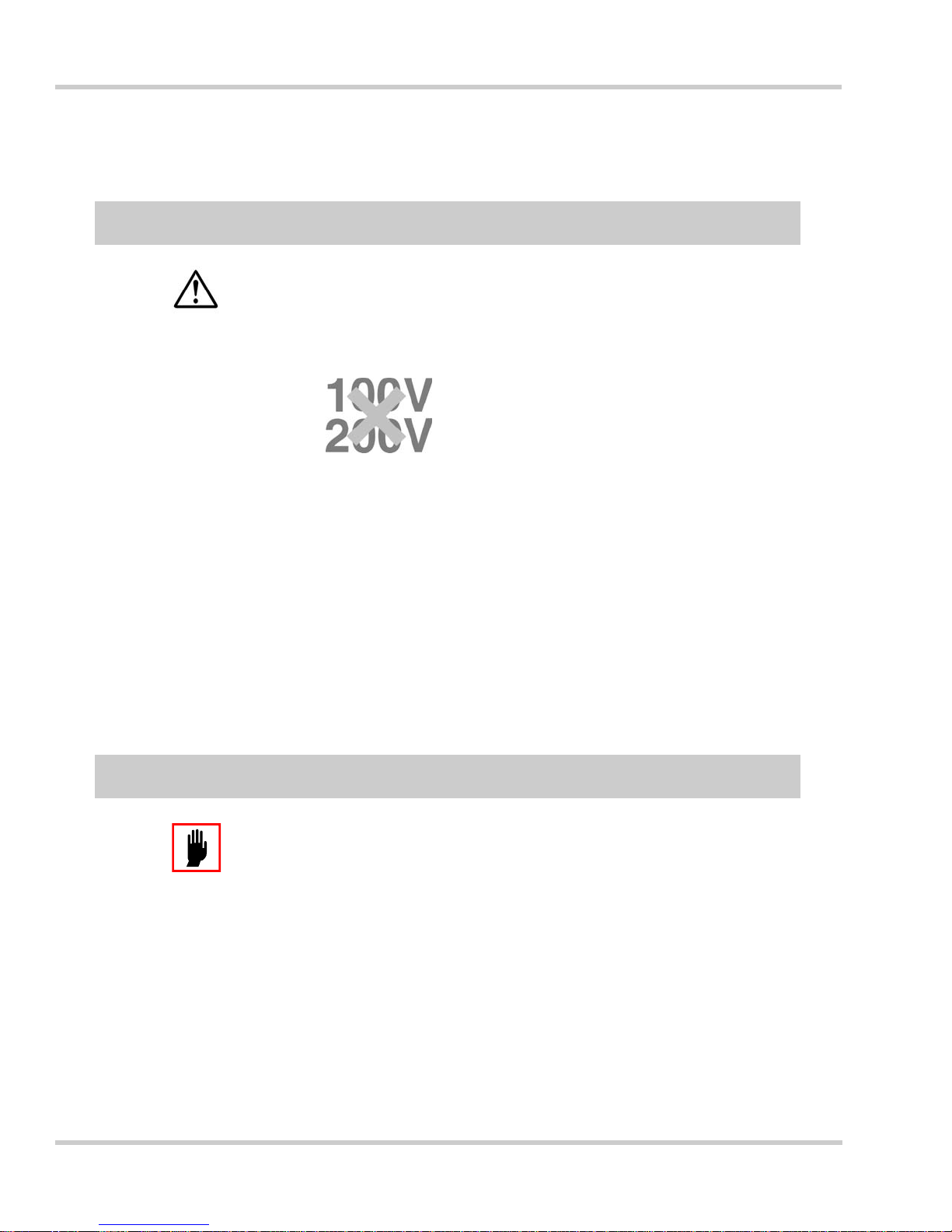
Use only on U.S. standard 120 V AC power.
Using any other voltage
source can cause product
failure or fire.
Do not use this product in countries other
than the United States and Canada, as the
product is designed for use in these
countries only.
Use in other countries can cause fire, electric
shock, and damage to the internal power s upply
because of voltage differences. Also
communication problem s can occur because o f
different telephone line parameters.
This product must be plugged into its own
independent wall outlet circuit.
Do not plug the po w er co rd into a wall outlet that
is also powering devices such as air
conditioners, copiers, or refrigerators, etc. Doing
so can cause improper operation due to power
surges caused by the other device.
The wall outlet must be able to handle the
amount of current to properly operate the
product.
The wall outlet circuit must be capable of
providing 11.5 amperes, or more, for proper
operation.
This is a warning that indicates a hazard that can lead to serious
injury or death
.
T one r Bottle and Imaging Unit
Cautions
Do not throw used toner bottles or imaging
units into an incin erator or fire.
The toner is highly flammable an d can cause a
fire to spread quickly.
This is a caut ion th at indica tes a hazar d that c an lea d to in jury o r
damage to property
.
Page 19

NEC IT Series Issue 1
NEC IT3 510/IT251 0 O perations M anual 13
Recommendations
Only use toner bottles and imaging units
specified by NEC America, Inc.
Use of unauthorized parts and consummables
may result in unit failure or a reduction in print
quality. In certain cases, this may also void the
machine’s warranty.
Do not store a toner bottle or imaging unit in
the following environments: Hot, humid or
dusty areas; areas near d irect flame; areas
in direct sunlight; areas near magnetically
sensitive objects (such as floppy disks, etc.);
in a vehicle or area where extreme
temperature variations can occur.
Doing so can result in poor print quality.
Do not ope n the wrapp ing of the tone r bottle
or imaging unit until it is to be used.
Doing so can result in poor print quality.
Do not store a toner bottle or imaging unit
upright or upside down.
Doing so can result in print failures.
Make sure the toner bottle or imaging unit is
not dropped or thrown.
Doing so can result in unit failure and/or poor
print quality.
Do not touch or scratch the surface of the
imaging unit’s photosensitive parts.
Doing so can result in unit failure or poor print
quality.
This is a recommendation that indicates a certain procedure
should be followed for proper performance.
Page 20

14 Regulatory and Safety Information
Issue 1 NEC IT Series
Print Paper
Recommendations
Only use the types specified by NEC
America, Inc. Do not use wrinkled, folded,
damp paper, or paper th at has already been
print ed on.
This can result in poor print quality or machin e
failure. For details concerning which types of
paper to use, consult your dealer.
Paper Stor age
Even paper that meets the required standards
will deteriorate if stored improperly. A
deterioration in paper quality may result in failure
of the paper feed mechanisms, a print paper
jam, or reduction in overall print quality.
The following items should be kept in mind when
storing print paper:
• Be sure to store the paper in a dry, low
humidly environment.
• Do not unwrap a ream of paper until it is
ready for use. The wrapping h elps keep out
moisture.
• Store the paper on a flat surface.
• Do not store the paper at floor level, as
humidity is generally hi gher at that location.
• Make sure that paper is not folded or curled
when stored.
• Do not store reams of paper on their en ds,
or stack too high.
• Do not store paper in areas of direct sunlight
or in places subject to large temperature
variations.
• If the paper is exposed to areas of high
humidity, leave the paper (while still in the
wrapper) in the area it is to be used for a
day, or more. This will assist condition the
paper to the proper environment.
This is a r ec ommendation that indicates a cert ain procedure
should be followed for proper performance.
Page 21

NEC IT Series Issue 1
NEC IT3 510/IT251 0 O perations M anual 15
Other Conditions of Use
Others
Normal international communications may
sometimes not be possible depending on the
telephone line status.
Many times international facsimile
communication is affected by various noise on
the telephone line. Items such as echoes, static,
timing problems, etc., can degrade a facsimile
communication. Many times the problem is
corrected when the unit interrupts a connection
and redials the destination .
The cooling fan comes on intermittently .
The product’s cooling fan is connected to a
thermostat. When the internal temperature
raises to a certain level, the cooling fan is
engaged to circulate coo l a ir throughout the unit.
Ventilate the area.
Ozone is produced as a normal by-product of t he
printer engine. The quantity of ozone is well
below the level that is harmful to your health.
However, the odor produced may b e unpleasant
if the unit is in an area with po or ventilation. In
such cases, be sure to properly maintain
ventilation in the room containing the machine.
If a Humidifier is used.
If tap or well water is use d in a room humidifier,
impurities in the water are discharged into the
room’s air supply. This can cause deposits to
build up inside the print engine and may cause
poor print quality. It is recommended to only use
distilled water which contains only minute
quantities of impurities.
When using 2-Sided Copying.
If 2-Sided Copying i s executed with the 2-Sided
Print Unit, paper printed on one side is ejected
onto the tray. This paper is then automatically
inserted to print on th e other side of the paper.
The purpose of t his operation is to turn over the
paper and is not a malfunction.
Do not pull out or touch the paper that is printed
on one side and ejected onto the tray.
Otherwise, copying may not be completed
properly, or a paper jam or other failure may
occur.
Page 22

16 Regulatory and Safety Information
Issue 1 NEC IT Series
SECTION 3LEGAL RESTRICTIONS TO COPYING
Copying of the following items are forbidden under certain circumstances. The list is
not all inclu sive a nd n o liabil ity is assum ed for it s compl eteness or accura cy. In case
of doubt, c ons ult an attorney.
Ë
Obligations or Securities of the Unites States Government, such as:
Bonds and obligati ons of cer t ain agenc ies of the government such as FHA, etc.
Bonds. (US Savings Bonds m ay be phot ographed only for p ublicity pu rposes in
connection with the campaign for the sale of such bonds.)
Internal Re venue Sta mps. (If it is neces sary to copy a legal documen t on which
there is a canceled revenue stamp, this may be done provided the reproduction of
the document is performed for lawful purposes.)
Postage Stamps - canceled or uncanceled. (For philatelic purposes, postage
stamps may be photograph ed provided the reproduction is in black and white and
is less than 3/4 or more than 1-1/2 times the linear dimensions of the original.)
Postal Money Orders.
Bills, Checks, or Drafts for Money drawn by or upon authorized officers of the
United States.
Stamps and other representatives of value, of whatever denomination, which have
been or may be iss ued und er any Act of Con gre ss .
Ë
Adjusted Compensation Certificates for War Veterans.
Ë
Obligations or Securities of any Foreign Government, bank, or Corporation.
Ë
Copyrighted material, unless permission of the copyright owner has been
obtained or the copyright falls within the "fair use" or library reproduction rights
provisions of the copyright law. Further information of these provisions may be
obtai ned from t he Co pyrigh t Of fi ce, Li bra ry of Congres s, W ashi ngt on, D .C. 2 0559.
Ask for Circu lar R21.
Ë
Certifica te s of C itizensh ip o r Naturalizati on . ( Foreign Natura l i zation Certif i cate s
may be photograp hed.)
Ë
Passpor ts. ( F oreign pa ssports may be photographed. )
Certi f icates of I ndebt edness
National Bank Currency
Coupons from Bonds
United States Bonds
Treasury Notes
Federal Reserve Notes
Federal Reserve Bank Notes
Silver Certificates
Gold Certificates
Fractional Notes
Certific at es of D eposit
Paper Money
Page 23

NEC IT Series Issue 1
NEC IT3 510/IT251 0 O perations M anual 17
Ë
Immigrat ion Pa per s.
Ë
Draft Registration Cards.
Ë
Selective Service Induction Papers which bear any of the following information:
Ë
Badges, Id entification Cards, Pa s s es , or Insignia ca rried by Military, Naval
personnel, or by members of the various Federal departments and bureaus, such
as FBI, CIA , Trea s ury, etc. (u nless a photogr aph is ordered by the head of such
department or bureau.)
Copying the follow ing is also prohibited in certain states: Au tomobile Licens es,
Driv ers’ Licenses, and A ut omobi le Certi f icat es of Title .
Registrant’s earnings or income
Registrant’s dependency statu s
Registrant’s Court record
Exceptions: U.S. Army and Navy
dischar ge certificates m ay be
photographed.
Reg i strant’s p r evious milita r y service
Registrant’s physica l or me nt al
condition
Page 24

18 Regulatory and Safety Information
Issue 1 NEC IT Series
Please check that the following accessories are enclosed before starting operations.
Please order consumables from your NEC authorized dealer when they run out.
Accessories
Operation Manual 1
Quick Reference Guide 1
Telephone line c ord 1
Power cord 1
Print paper size label 1 set
Imaging Unit 1
Consumables
Imaging Unit
Toner bottle
Stamp cartridge (for optional stamp unit)
Staple cartridge (for optional Single-staple Finisher,
Multi-staple Finisher, Mail-bin Finisher)
Useful Information
Page 25
NEC IT Series Issue 1
NEC IT3 510/IT251 0 O perations M anual 19
Specifications
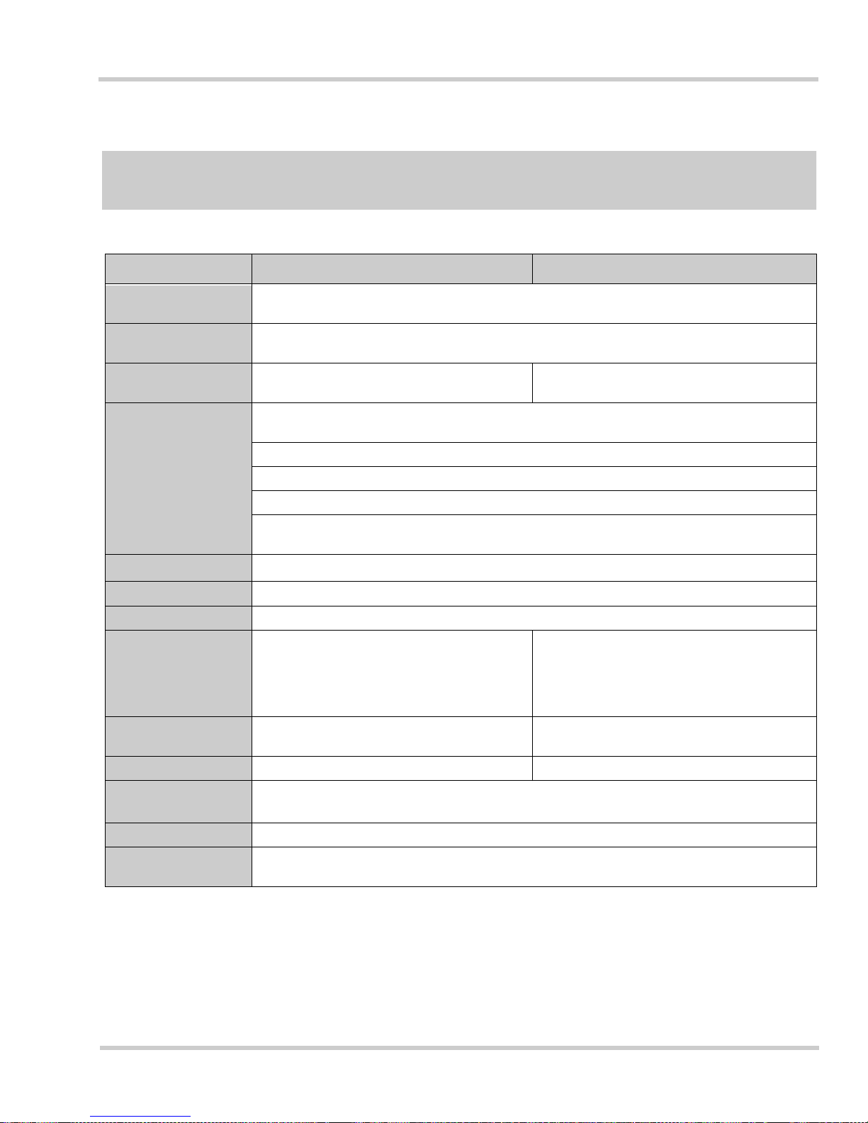
Product Number
IT3510 IT2510
Communication
standard
G3
Applicable
communication lines
Public Switched Telephone Network (PSTN)
Standard cassette
Multi-purpose cassette
550-sheet cassette
Multi-purpose cassette
Paper sizes
Multi-purpo se cassette: 11x17, 11x14, Legal, Letter, Letter(Landscap e), 5 1/2 x 8 1/2,
5 1/2 x 8 1/2 (Landscape)
Universal Cassette (*1): 11x17, 11x14, Legal, Letter, Letter(Landscape), FLS
550-sheet cassettes: 11x17, 11x14, Legal, Letter, Letter(Landscape)
Large Capacity Cabinet (*1): Letter
Manual Bypass Tray: 11x17, Legal, Letter, Letter(Landscape), 5 1/2 x 8 1/2, 5 1/2 x 8 1/2
(Landscape)
Paper types
Standard paper (60 to 90g/m
2
), Recy cled paper, Ca r d (91 to 157gm2), OHP sheets
Recording system Electronic photographic recording system
Power requirements 120VAC, 50/60Hz, 11.5A
Power consumption
(*3)
Stand-by/Power Saving Mode :approx. 30W
Transmission Mode :approx. 40W
Reception Mode :approx. 40W
Copying Mode :approx. 790W
Maximum :approx. 1450W
Stand-by/Power Saving Mode :approx. 30W
Transmission Mode :approx. 40W
Reception Mode :approx. 40W
Copying Mode :approx. 700W
Maximum :approx. 1450W
External dimensions
(*3)
616 x 707 x 761mm (WxDxH) 616 x 707 x 656mm (WxDxH)
Weight (*3) 132 lbs (60kg) 119 lbs (54kg)
Required environment
Temperatu re: 27.1
o
F (10oC) to 87.8oF (31oC)
Humidity: 15 to 80%
DC resistance 334 ohms
Ni-MH battery for
memory back-up
Voltage: 4.8V
Capacity: 650mAh (*2)
(*1) Optional
(*2) The Ni-MH battery for memory back-up should not be replaced by the user. Contact your service center for
replacement i n case of failure.
(*3) For Automatic Document Feeder model (excl uding optional products)
Page 26
20 Regulatory and Safety Information
Issue 1 NEC IT Series
The following optional parts are available for the NEC IT3510/IT2510. These allow for
more efficient and convenient operation.
Ë
Optional Memory Board
8 MB, 16 MB, 32 MB - This memory option increases the document storage
capacity. This is convenient when scanning and copying large volumes of
docume nts. It also allow s for more re ceived documen t storage, if t he machine
should run out of print paper.
Ë
Paper Cassettes
Up to five layers of cassettes, including the standard cassette(s), can be installed.
If additional cassettes are used to employ different sizes of copy paper, the
appropriate size paper is automatically selected for printing.
Ë
2-Sided Print Unit (Duplex Unit)
Allows printing on both sides of the print paper. Ideal for reports, books, and
publicat ions, etc.
Ë
Job Tray Unit
Off ers sor ti ng by the user designa ti ng which tray gets copie r output and which tray
gets facsim ile printed output.
Ë
Shift Tray Unit
Offers sorting of all print ed output by m eans of mech anical shift collation.
Ë
Mail-bin Finisher
Enables sorting, stapling, and hole punching. Includes five individual mail-bins for
indi v idual network print ing output.
Ë
Single-staple Finisher
Off ers finishi ng features inc luding sorting and stapli ng.
Ë
Multi-staple Finisher
Offers finishing features including sorting, dual stapling, and hole-punching.
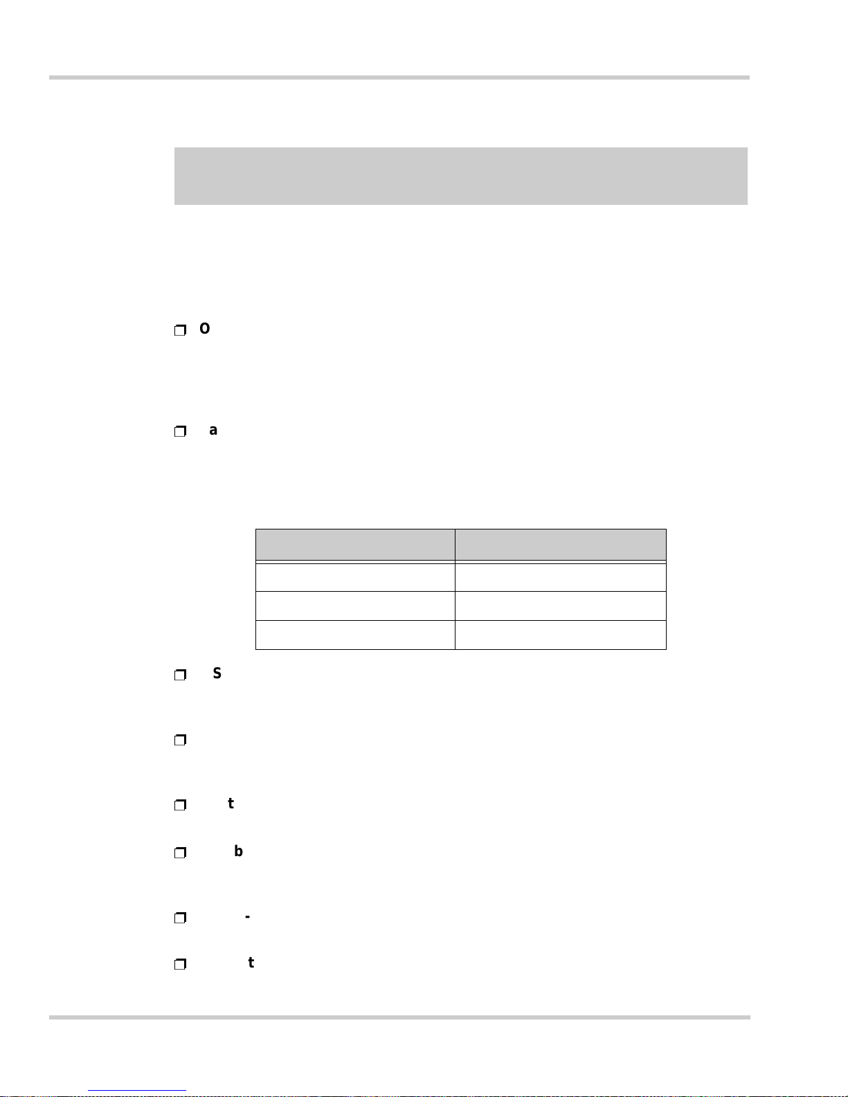
Types of Paper Cassettes Paper Capacity
Universal Paper Cassette 550 sheets
Fixed Universal Cassette 550 sheets
Large Capacity Cabinet 2, 750 sheets
Options
Page 27

NEC IT Series Issue 1
NEC IT3 510/IT251 0 O perations M anual 21
Ë
Mechanical Counter
A six-digit counter for printed page count. This is an additional counter to the
internal soft counter.
Ë
Network Interface Application Kit
Offers e-mail document communications to PCs. Also offers scanner features
and fax-to-e-mail translation and communication.
Ë
PC Printer Controller
Offers PC pri nting and av a ilab le n et work print in g. Pri n ter drive rs ( P CL6 and PS) ,
and mem ory upgrade available. Dri vers include integration t o available finis hing
options.
Ë
Second G3 Port
A second facsimile line ca n be inst alled, allowing the conv enienc e and effic iency
of simulta neous sending and receiving .
Ë
Third Tray Unit
This tray au tomatica lly sorts the printed output from the printer or facsim ile. Can
be equipped with the Single-staple Finisher, or the Multi-staple Finisher.
Ë
Large Capacity Battery
Allows up to 72-hour image back-up for storing documents in memory. In the
event of a power failure, the battery keeps images in memory that would have
otherwise been erased.
Ë
Deck, Cabinet(s)
Optional deck and cabinet(s) allow for height adjustments after add ing optional
cassettes.
Ë
TX Marker
The TX Marker stamps a small red circle on the document, showing the user that
the individual pages were successfully scanned into memory.
Page 28

22 Regulatory and Safety Information
Issue 1 NEC IT Series
THIS PAGE INTENTIONALLY LEFT BLANK
Page 29

NEC IT35 10/ I T 2510 Operations Ma nual i
Table of Contents
Regulatory and Safety Information
Section 1 Regulatory Information ..................................................................1
1.1 FCC Notification ........................................................................................1
1.2 Industry Canada Notification .....................................................................3
1.3 Laser Classification and Safety .................................................................4
1.4 CDRH Regulations ....................................................................................5
1.5 Transmitter Su bscriber ’s Identification ......................................................6
Section 2 Safety Precautions .........................................................................7
2.1 Installation Space ......................................................................................7
2.2 Using this Product ....................................... .......... ......... ......... ..................8
Section 3 Legal Restrictions To Copying ....................................................16
Chapter 1 Getting Started
Section 1 Product Overview ........................................................................1-1
Section 2 Names and Functions of Parts ...................................................1-3
Section 3 Operation Panel and Touch Panel .............................................1-9
3.1 Operation Panel ......................................................................................1-9
3.2 Touch Panel .........................................................................................1-11
3.3 Stand-by Screen (Initial Screen) ...........................................................1-14
3.4 Users and User Management Mode ...................... ......... ......... .......... ...1-21
Section 4 How to use the Copier and Facsimile (Auto-mode Screen) ..1-24
Page 30

Issue 1 NEC IT Series
ii Table of Contents
Section 5 Handling Documents ................................................................ 1-25
5.1 Using the Automatic Document Feeder (ADF) .....................................1-25
5.2 Using the Book Scanner ...................... ......... ......... .......... .....................1-26
5.3 Using the Single Feed Tray ................. ......... ......... ............................ ...1-26
5.4 Notes on Handling Documents .............................................................1-27
Section 6 Quitting an Operation ............................................................... 1-30
Section 7 Interrupting an Operation ......................................................... 1-32
7.1 Interrupting ............................................................................................ 1-32
Section 8 Confirming the Settings ........................................................... 1-33
Section 9 Routine Care .............................................................................. 1-37
9.1 Installing Print Paper .............................................................................1-37
9.2 Installing and Replacing the Imaging Unit and Toner Bottle .................1-53
9.3 Installing and Replacing the Toner Bottle .............................................1-56
9.4 Installing and Replacing the Transmission (TX) Marker Stamp ............1-59
9.5 Installing and Adding Staples ...............................................................1-62
9.6 Replacing the Staple Cartridge .............................................................1-65
9.7 Cleaning ................................................................................................1-70
Chapter 2 Copy Operations
Section 1 Basic Copy Operations .............................................................. 2-1
1.1 Copying with the Automatic Document Feeder ......................................2-2
1.2 Copying with the Book Scanner ..............................................................2-3
1.3 Memory Recall ........................................................................................2-5
1.4 Selecting the Copy Paper Size for Copying ............................................2-6
1.5 Paper Size Reset ..................................................................................2-13
Page 31

NEC IT Series Issue 1
NEC IT35 10/IT2510 Operation s Manual iii
1.6 Selecting the Zoom Ratio for Copying ..................................................2-13
1.7 Selecting the Zoom Ratio ................... ............................ ......... .............2-14
1.8 Zoom Selections Available ................................................................2-15
1.9 Registering the Zoom Ratio ..................................................... .............2-17
1.10 Using the Registered Zoom Ratio for Copying .................................. ...2-18
1.11 Zoom Ratio Reset ............................... ......... .......... ......... ......... .......... ...2-18
1.12 Adjusting the Density for Copying ......................... ...............................2-18
1.13 Making the Choice for Density Selection ..............................................2-20
1.14 Density Setting Reset ...........................................................................2-20
1.15 Copying Figures and Photos .............................................................2-21
1.16 Image Quality Setting Reset .................................................................2-22
Section 2 Advanced Copy Operations .....................................................2-23
2.1 Using the Sort Mode While Copying ........................................ .......... ...2-23
2.2 Stapled Binding ....................................................................................2-26
2.3 Hole Punching ............................................. .......... ......... ......... .......... ...2-29
2.4 Mixed Size Original Document Detection .............................................2-32
2.5 Selecting the Document and Copy Format (Orig.Copy Screen) .......2-34
2.6 Selecting Format s for Various Original Documents ..............................2-40
2.7 Selecting the Various Copy Formats ....................................................2-43
2.8 Attaching Cover Sheets to Copies ........................................................2-50
2.9 Inserting Separa tors (Pa ge Insertion) ............................. ......................2-53
2.10 Copying and Overhead Projector Interleaving ......................................2-56
2.11 Setting Up File Margins ............. ......... ......... .......... ............................ ...2-59
2.12 Erasing a Portion of the Document .......................................................2-61
2.13 Repeated Copying on a Single Sheet ..................................................2-62
2.14 Numbering Each Set of Copies ............................................................2-66
Page 32

Issue 1 NEC IT Series
iv Table of Contents
2.15 Separate Scanning .................... .......... ............................ ......... ......... ...2-68
2.16 Using Copy Programs ................................... ............................ ......... ...2-70
Chapter 3 R egistration and Setting Operations
Section 1 General Information .................................................................... 3-1
1.1 Describing the Registration and Setting Screens ...................................3-1
1.2 Administrator Managemen t Screen ........................................................3-2
1.3 Initial Setting Screen (Default Setting) ....................................................3-2
1.4 Required Initial Registration/Settings and Confirmation .........................3-4
1.5 Entering Characters for Registration ......................................................3-5
Section 2 Basic Settings and Registration Operation .............................. 3-7
2.1 Basic Settings .........................................................................................3-7
2.2 Accessing the Administrator Management Screen ...............................3-12
2.3 Registering the Self-ID .................................. ........................................3-14
2.4 Registering the Self-Telephone Number ........................................... ...3-16
2.5 Registering the Transmitter Su bscriber’s Identification (TSI) ...............3-17
2.6 Setting the Line Type ............................................................................3-19
2.7 PSTN/Extension Line Switch ........................ ......... .......... .....................3-20
2.8 Setting the Initial Screen to Display (Priority Screen) ...........................3-22
2.9 Setting the Priority Facsimile Screen ....................................................3-24
2.10 Settings for Received Documents ........................................................3-27
2.11 Registering Passwords for Secured Communications ..........................3-31
2.12 Setting the Management Mode .............................................................3-32
2.13 Registering the Administrator Number ...................................... ......... ...3-34
2.14 Setting the Image Memory Holding Timer ............................................3-35
2.15 Registering Users ................................ ............................ ......... ......... ...3-37
Page 33

NEC IT Series Issue 1
NEC IT35 10/IT2510 Operation s Manual v
2.16 Registering One-Touch Keys .................................................. .......... ...3-50
2.17 Registering Abbreviated Numbers ........................................... .......... ...3-58
2.18 Registering an Index for One-Touch Keys ...........................................3-66
2.19 Registering Program Keys ........................... .......... ......... ......... .......... ...3-67
Chapter 4 Advanced Regi s t r atio n an d Settin g Oper ation s
Section 1 General Information ....................................................................4-1
Section 2 Advanced Settings ......................................................................4-1
2.1 Transmission Settings ............................................................................4-1
2.2 Setting the Reception Mode ........................................... ......... .......... .....4-7
2.3 Report Print Settings ............................................................................4-17
2.4 Copy Settings .......................................................................................4-19
2.5 Printing Settings ...................................................................................4-27
2.6 Power Saving Settings ................................................... ......... .............4-30
2.7 Confirming the Usage Status of Each User ..........................................4-34
2.8 Amending User Data ............................................................................4-35
2.9 Confirming the Page Counte rs .............................. ......... ......... .............4-48
Section 3 Advanced Registration .............................................................4-51
3.1 Registering Relay Groups ..................................... ......... ......... .......... ...4-51
3.2 Registering a Self-Abbreviated Numbe r ...............................................4-53
3.3 Establishing a Bulletin Board ................................................................4-54
3.4 Registering Copy Programs ........................ ............................ .......... ...4-59
Chapter 5 Basic Sending and Receiving Operations
Section 1 General Introduction ...................................................................5-1
Section 2 Basic Sending Operations ..........................................................5-1
Page 34

Issue 1 NEC IT Series
vi Table of Contents
2.1 Quick Memory Transmission ..................................................................5-1
2.2 Calling the Destination and Transmitting the Document .........................5-5
2.3 Selecting the Communications Mode
(For optional 2nd G3 Port only) ...........................................................5-5
2.4 Using Full Dialing for International Destinations .....................................5-6
2.5 When Transmission is Unsuccessful ......................................................5-6
2.6 Using One-Touch Dialing .............................. ......... .......... ......... ..............5-7
2.7 Using Abbreviated Dialing ......................................................................5-9
2.8 Using Program Dialing Keys .............................................................. ...5-10
2.9 Sending Fine Print and Photos .............................................................5-12
2.10 Adjusting Contrast ................................................................................5-14
2.11 Sending Documents without Reduction ................................................5-15
2.12 Selecting the Scan Area .......................................................................5-18
2.13 Using Chain Dialing .......... ........................................................ ......... ...5-20
Section 3 Basic Receiving Operations ..................................................... 5-24
3.1 Changing the Reception Mode .............................................................5-24
3.2 While Receiving a Document ................................................................5-25
3.3 When the Recording Paper Runs Out ..................................................5-25
3.4 Paper Sizes and Document Formats ....................................................5-26
3.5 When Receiving Long Documents .......................................................5-26
3.6 Making and Receiving Telephone Calls ...............................................5-27
Chapter 6 Advanced Sending and Receiving Operations
Section 1 General Information .................................................................... 6-1
Section 2 Advanced Transmission Operations ......................................... 6-1
2.1 Confirming the Communications Status .................................................6-1
Page 35

NEC IT Series Issue 1
NEC IT35 10/IT2510 Operation s Manual vii
2.2 Serial Broadcast Transmission .............................. ......... ......... .......... .....6-7
2.3 Manual Transmission .................................. ...........................................6-9
2.4 Relay Transmission ..............................................................................6-11
2.5 Real-Time Transmission .......................................................................6-12
2.6 Priority Transmission ............................................................................6-14
2.7 Timer Transmission ..............................................................................6-15
2.8 2-TO-1 Transmission ............................................................................6-16
2.9 2-Sided Transmission ...........................................................................6-17
2.10 Using the TX Marker .............................................. ......... ......... .......... ...6-19
2.11 Printing TSI Information ........................................................................6-21
2.12 Destination Insertion .............................................................................6-22
2.13 Printing the Transmission Report ............................................ .......... ...6-23
2.14 Remote Copying ...................................................................................6-24
2.15 Password Transmission .......................................................................6-26
2.16 Polling Transmission ............................................................................6-27
2.17 F CODE .................. ........................................................ ......... .............6-29
2.18 Registering a Document on a Bulletin Board ........................................6-33
Section 3 Advanced Reception Operations .............................................6-36
3.1 Manual Reception .................................................................................6-36
3.2 Password Reception .............................................................................6-37
3.3 Selecting Password Reception .................... .......... ......... ......... .............6-38
3.4 Receive Polling and Start Time r .............................................. .............6-38
3.5 Retrieving from a Bulletin Board ...........................................................6-39
Chapter 7 Reports and Lists
Section 1 Reports and Lists ........................................................................7-1
Page 36

Issue 1 NEC IT Series
viii Table of Contents
1.1 Printing the Activity Report (TX) ............................................................. 7-1
1.2 Printing the Activity Report (RX) ............................................................. 7-3
1.3 Bulletin Board List ......................................... ......... ............................ .....7-4
1.4 Printing the User List ..............................................................................7-6
1.5 Printing the User Account Report ...........................................................7-8
1.6 Printing the Setting List .........................................................................7-10
1.7 Printing the One-Touch Ke y List ............................................... ......... ...7-12
1.8 Printing the Abbreviated Dial Number List ............................................7-13
1.9 Printing the Program List ......................................................................7-15
1.10 Printing the Relay Group List ................................................................7-16
Chapter 8 Troubleshooting
Section 1 Display Icons and Alarm Messages .......................................... 8-1
1.1 Display Icons ..........................................................................................8-1
1.2 Alarm Messages ....................................................................... ......... .....8-2
1.3 Document Jam ..................................... ......... ......... .......... ......... ......... .....8-6
Section 2 Troubleshooting ........................................................................ 8-27
Section 3 Power Failure ............................................................................ 8-33
3.1 Documents in Memory are Retained for Two Hours .............................8-33
3.2 Registered Items are Retained .............................. .......... ......... ............8-33
3.3 Making a Telephone Call is not Permitted ............................................8-34
Section 4 Anti-Dew Function .................................................................... 8-34
Section 5 Toner Replenishment ............................................................... 8-36
Appendix A Glossary of Terms
Page 37

NEC IT35 10/ I T 2510 Operations Ma nual ix
List of Figures
Figure 1-1 Names and Functions of Parts ...................................................................................1-3
Figure 1-2 Location of the Brightness Control .............................................................................1-4
Figure 1-3 Open Document Cover ...............................................................................................1-4
Figure 1-4 Detaching the Document Feed Tray ..........................................................................1-5
Figure 1-5 Back View of the NEFAX IT3510 ...............................................................................1-6
Figure 1-6 Optional Equipment for Additional Efficiency .............................................................1-7
Figure 1-7 TX Marker Location .................................................................................................... 1-8
Figure 1-8 Operations Panel Components ..................................................................................1-9
Figure 1-9 Touch Panel Display ................................................................................................1-11
Figure 1-10 User Selection Screen ..............................................................................................1-12
Figure 1-11 Utility Screen ............................................................................................................1 -12
Figure 1-12 Status Display ..........................................................................................................1-13
Figure 1-13 Auto-mode Screen ...................................................................................................1-15
Figure 1-14 Copy Screen ................................... ..........................................................................1-16
Figure 1-15 One-Touch Screen ...................................................................................................1-17
Figure 1-16 Abbreviated Dialing Screen ........................... ...........................................................1-18
Figure 1-17 10-key Dialing Screen ..............................................................................................1-19
Figure 1-18 Index List Screen ...................................................................................................... 1 -20
Figure 1-19 Loading the Automatic Document Feeder ................................................................1-25
Figure 1-20 Using the Book Scanner ...........................................................................................1-26
Figure 1-21 Using the Single Feed Tray ......... ................................. ........................................... .1-27
Figure 1-22 Maximum and Minimum Document Sizes ..... ...................... ................................. ....1-29
Figure 1-23 Pressing the Stop Key ..............................................................................................1-30
Page 38

Issue 1 NEC IT Series
x List of Figures
Figure 1-24 Selecting Which Operation to Cancel .......................................................................1-31
Figure 1-25 Pressing the Panel Reset Key ..................................................................................1-31
Figure 1-26 Touching Cancel on the Touch Panel ......................................................................1-32
Figure 1-27 Pressing the Interrupt Key ........................................................................................1-33
Figure 1-28 Pulling Out the Paper Cassette ................................................................................1-38
Figure 1-29 Locking the Paper Support .......................................................................................1-38
Figure 1-30 Loading the Paper Cassette .....................................................................................1-39
Figure 1-31 Pushing In the Paper Cassette .................................................................................1-39
Figure 1-32 Pulling Out the Paper Cassette ................................................................................1-40
Figure 1-33 Locking the Paper Support .......................................................................................1-40
Figure 1-34 Adjusting the Paper Width Guide .............................................................................1-41
Figure 1-35 Adjusting the Paper Length Guide ............................................................................1-41
Figure 1-36 Loading the Paper Cassette .....................................................................................1-42
Figure 1-37 Pushing In the Paper Cassette .................................................................................1-42
Figure 1-38 Changing Paper Size and Type Screen ...................................................................1-43
Figure 1-39 Selecting the Paper Size Screen ..............................................................................1-43
Figure 1-40 Selecting the Paper Type Screen .............................................................................1-44
Figure 1-41 Pulling Out the Paper Cassette ................................................................................1-44
Figure 1-42 Locking the Paper Support .......................................................................................1-45
Figure 1-43 Loading the Paper Cassette .....................................................................................1-45
Figure 1-44 Pushing In the Paper Cassette .................................................................................1-46
Figure 1-45 Pulling Out the Paper Cassette ................................................................................1-46
Figure 1-46 Locking the Paper Support .......................................................................................1-47
Figure 1-47 Loading the Paper Cassette .....................................................................................1-47
Figure 1-48 Pushing In the Paper Cassette .................................................................................1-48
Figure 1-49 Pulling Out the Paper Cassette ................................................................................1-48
Page 39

NEC IT Series Issue 1
NEC IT35 10/IT2510 Operation s Manual xi
Figure 1-50 Locking the Paper Support .......................................................................................1-49
Figure 1-51 Adjusting the Paper Width Guide ............................. ............................................ ....1-49
Figure 1-52 Adjusting the Paper Length Guide ...........................................................................1-50
Figure 1-53 Loading the Paper Cassette .....................................................................................1-50
Figure 1-54 Pushing In the Paper Cassette ............... ........... ... ........... ................................. ........1-51
Figure 1-55 Pulling Out the Paper Cassette ............................................... ................................ .1-51
Figure 1-56 Loading the Paper Cassette .....................................................................................1-52
Figure 1-57 Pushing In the Paper Cassette ............... ........... ... ........... ................................. ........1-52
Figure 1-58 Opening the Side Cover ...........................................................................................1-53
Figure 1-59 Opening the Side Cover ...........................................................................................1-54
Figure 1-60 Pulling Out the Used Imaging Unit ............................... ... ........... ..............................1-54
Figure 1-61 Removing the Packing Items from Imaging Unit ......................................................1-55
Figure 1-62 Shaking the New Imaging Unit .................................................................................1-55
Figure 1-63 Inserting the New Imaging Unit ................................................................................1-55
Figure 1-64 Closing the Side Cover .............................................................................................1-56
Figure 1-65 Opening the Toner Bottle Cover ...............................................................................1-56
Figure 1-66 Removing the Old Toner Bottle ................................................................................1-57
Figure 1-67 Gently Shake the New Toner Bottle .........................................................................1-57
Figure 1-68 Turn the Bottle to Loosen the Toner .........................................................................1-57
Figure 1-69 Remove the Sticker Sealing the Bottle .....................................................................1-58
Figure 1-70 Inserting the New Toner Bottle .................................................................................1-58
Figure 1-71 Closing the Toner Cover ..........................................................................................1-59
Figure 1-72 Lifting the Document Feed Tray ...............................................................................1-60
Figure 1-73 Removing the Used Marker ......................................................................................1-60
Figure 1-74 Installing a New Marker ............................................................................................ 1 -61
Figure 1-75 Lowering the Document Feed Tray ..........................................................................1-61
Page 40

Issue 1 NEC IT Series
xii List of Figures
Figure 1-76 Opening the Stapling Unit Cover ..............................................................................1-62
Figure 1-77 Removing the Stapling Unit ................................................................... ...................1-62
Figure 1-78 Removing the Stapling Holder ...................................... ............................................1-63
Figure 1-79 Removing the Empty Cartridge ................................................................................1-63
Figure 1-80 Inserting the New Staple Cartridge ...........................................................................1-63
Figure 1-81 Installing the Refilled Staple Holder ..........................................................................1-64
Figure 1-82 Align Arrows on the Stapling Unit .............................................................................1-64
Figure 1-83 Locking the Stapler Cover ........................................................................................1-64
Figure 1-84 Removing a Staple Jam ...........................................................................................1-65
Figure 1-85 Cleaning the External Surfaces ................................................................................1-70
Figure 1-86 Displaying the Panel Cleaning Screen .............. .......................................................1-71
Figure 1-87 Panel Cleaning Mode ...............................................................................................1-71
Figure 1-88 Cleaning the Touch Panel ........................................................................................1-72
Figure 1-89 Reset the Touch Panel Screen .................................................................................1-72
Figure 1-90 Open the Document Cover .......................................................................................1-72
Figure 1-91 Cleaning Areas .........................................................................................................1-73
Figure 1-92 Clean White Rollers ..................................................................................................1-73
Figure 1-93 Close the Document Cover ......................................................................................1-74
Figure 1-94 Lifting the Document Hopper ....................................................................................1-74
Figure 1-95 Cleaning the Document Feed Rollers .......................................................................1-74
Figure 1-96 Cleaning the Four Lower Rollers ..............................................................................1-75
Figure 1-97 Close the Hopper and Hopper Cover .......................................................................1-75
Figure 1-98 Cleaning the Document Transport Belt ....................................................................1-76
Figure 1-99 Pull the Document Transport Belt .............................................................................1-76
Figure 1-100 Cleaning the New Belt Surface .................................................................................1-77
Figure 3-1 Main Registration and Setting Displays ......................................................................3-1
Page 41

NEC IT Series Issue 1
NEC IT35 10/IT2510 Operation s Manual xiii
Figure 3-2 Administrator Management Screen ............................................................................3-2
Figure 3-3 ID Screen ...................................................................................................................3-2
Figure 3-4 Line Screen ................................................................................................................3-3
Figure 3-5 Function Screen .........................................................................................................3-3
Figure 3-6 Management Screen ..................................................................................................3-3
Figure 6-1 TX Marker Position ...................................................................................................6-20
Figure 7-1 Activity Report (TX) Example .....................................................................................7-2
Figure 7-2 Activity Report (RX) Example .....................................................................................7-4
Figure 7-3 Bulletin Board List Example .......................................................................................7-5
Figure 7-4 User List Examples .................................................................................................... 7-8
Figure 7-5 User Account Report Example .................................................................................7-10
Figure 7-6 Setting List Example .................................................................................................7-11
Figure 7-7 One-Touch Key List Example ...................................................................................7-13
Figure 7-8 Abbreviated Dial Number List Example .................... ........... ................................. ....7-14
Figure 7-9 Program List Example ..............................................................................................7-16
Figure 7-10 Relay Group List Example ........................................................................................7-17
Figure 8-1 Memory Clear Report Example ................. ...................... .........................................8-33
Page 42

Issue 1 NEC IT Series
xiv List of Figures
THIS P AGE INTENTIONALLY LEFT BLANK
Page 43

NEC IT35 10/ I T 2510 Operations Ma nual xv
Table 1-1 Standard Icons ............................................................................................................1-13
Table 2-1 Sorting / Grouping with Options ..................................................................................2-25
Table 2-2 Corner Stapling Position ..............................................................................................2-28
Table 2-3 2-Point Stapling Position .................................. ...........................................................2-28
Table 2-4 Stapled Number of Pages Per Copied Set ........................................... ......................2-29
Table 2-5 Hole Punching Position ...............................................................................................2-31
Table 2-6 Examples of Copying Mixed Documents .....................................................................2-32
Table 8-1 Display Icons ....................................... ........................................................................8-1
Table 8-2 Alarm Messages ..........................................................................................................8-2
List of Tables
Page 44

Issue 1 NEC IT Series
xvi List of Tables
THIS P AGE INTENTIONALLY LEFT BLANK
Page 45

NEC IT3 510/IT25 10 O perations M anual 1 - 1
Chapter 1
Getting Started
SECTION 1PRODUCT OVERVIEW
The NEC IT3510 and IT2510 provide an all-in-one document solution for today’s
busines s necessities. The units offer a full co mplement of features includi ng digital
copier and document finishing capabilities, facsimile, network printing, and e-mail
messaging. The NEC IT Series products are document solutions systems unto
themselves.
Both units offe r corporate workgroups and satellit e offices a compre hensive sol ution
for infor mation and ce ntraliz ed doc umen t capabi lities. Starti ng with the 35 pag e per
minute (IT3510) and 25 page per minute (IT2510) print speed and half second
docume nt s c anning speed, the foundation is built for your customer’s total d o cu ment
solution.
The standard digital copier offers 600 dpi resolution, offering outstanding copy quality
for the most demanding applications. Memory recall, page insertion, distribution
numberin g, edge ad jus tm e nt, and im a ge rep ea t are am o ng the m an y copier f eature s
available.
A full l ine of doc u men t fi nish ing f eatu res are also a vai l abl e. S tapli ng, hol e p unching,
watermar ks, rotation sorting, a nd cover sheet inse rtion all al low your N EC IT Seri es
unit to become a document publication center.
Duplex printing and duplex scanning round-out this impressive line-up of features
available on both units.
The NEC I T Serie s also offers you a fu ll line o f upgrad e optio ns: dual p orts, net work
printing and network extensions allow for a life-long upgrade path for the products.
As a hub facsimile unit, the IT Series offers leading-edge features and functions:
quick memory transmission, dual port upgrade path, 24 MB of standard facsimile
memory, double-sided original transmission, 500 location auto-dialing, subaddressing, and fully integrated touch screen display.
The network printer module supports the popular network protocols and makes
available PCL6 and PostScript-3. The NEC IT Series and the network printer module
deliver solutions for printing and document finishing functionality within the entire
network, all from the desktop.
Page 46

1 - 2 Gett ing Star t ed
Issue 1 NEC IT Series
The network ex tension module is a technical innov a tion that allows the NEC IT Ser ie s
to evolve into you customer’s e-mail and Internet communications network.
One-touch Document E-mail: allows users to walk-up and e-mail their paper
documents directly to any e-mail address.
E-mail RX-FAX Distribution: receives facsimiles to the IT Series unit which
automatically converts it into a file and e-mails the message to designated e-mail
addresses.
Network File Scan ni ng (IP): offers network scanni ng t o a f ile in your PC.
One-Touch Network File TX: allows you to transmit a paper document over the IP
network into a file in a network connected computer.
Page 47
NEC IT Series Issue 1
NEC IT3510/IT2510 Operations Manual 1 - 3
SECTION 2NAMES AND FUNCTIONS OF PARTS
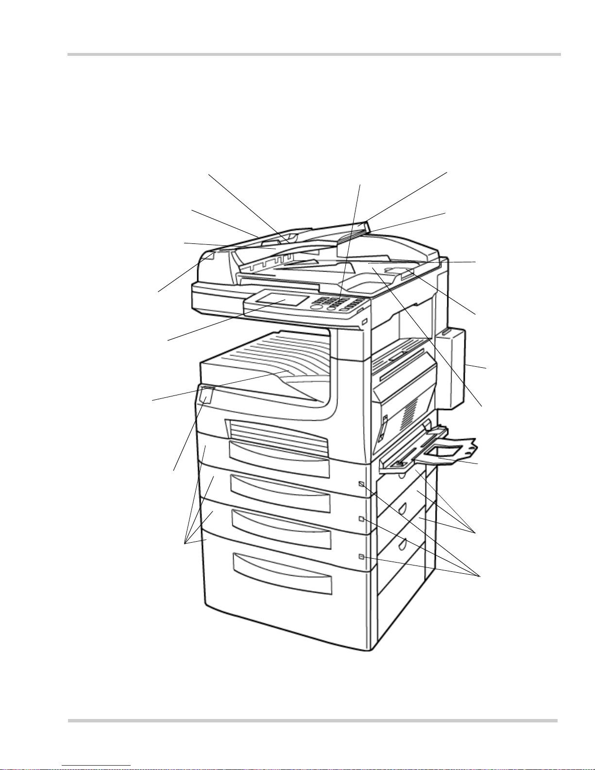
This section names an d explains the basic functio ns of various pa rts of the pro duct.
For a description of the operation panel, refer to Section 3 Operation Panel and
Touch Panel.
Figure 1-1 Names and Functions of Parts
Operation Panel
Automatic Document
Feeder
Document Feeder
Cover
Document Guide
Plate
Adjustable to th e width
of the do cumen t
Print Lamp
Green du rin g pr in ti ng,
red if a print alarm is
generated
Touch Panel
User interface for entering
and registering
information
Exit Tray
Print paper ex its the
printer in this area
Power Switch
Cover
The pow er swi tc h is
covere d to prevent
accide ntal shut off
Paper Cassettes
No Paper
Lamp
Turns on when the
print paper runs o ut
Document Feed Tray
Holds the document when
feeding. Removable.
Extension Guid e
Can be pull ed out to hold lon g
pages such as lega l or le dger
sizes
Document
Cover
To be open ed for
using the book
scanner
Stopper
The stopper prevents
long scanned pages
from slidin g off the
unit
Toner Cover
This door covers
the toner bottle
Document Exi
t
Tray
Scanne d pag es are
fed out here
Manual
Bypass Tray
This tra y is for
manual ly feeding
single sheets,
envelopes, etc.
Side Covers
Can be opened to
remove a paper
jam
Page 48
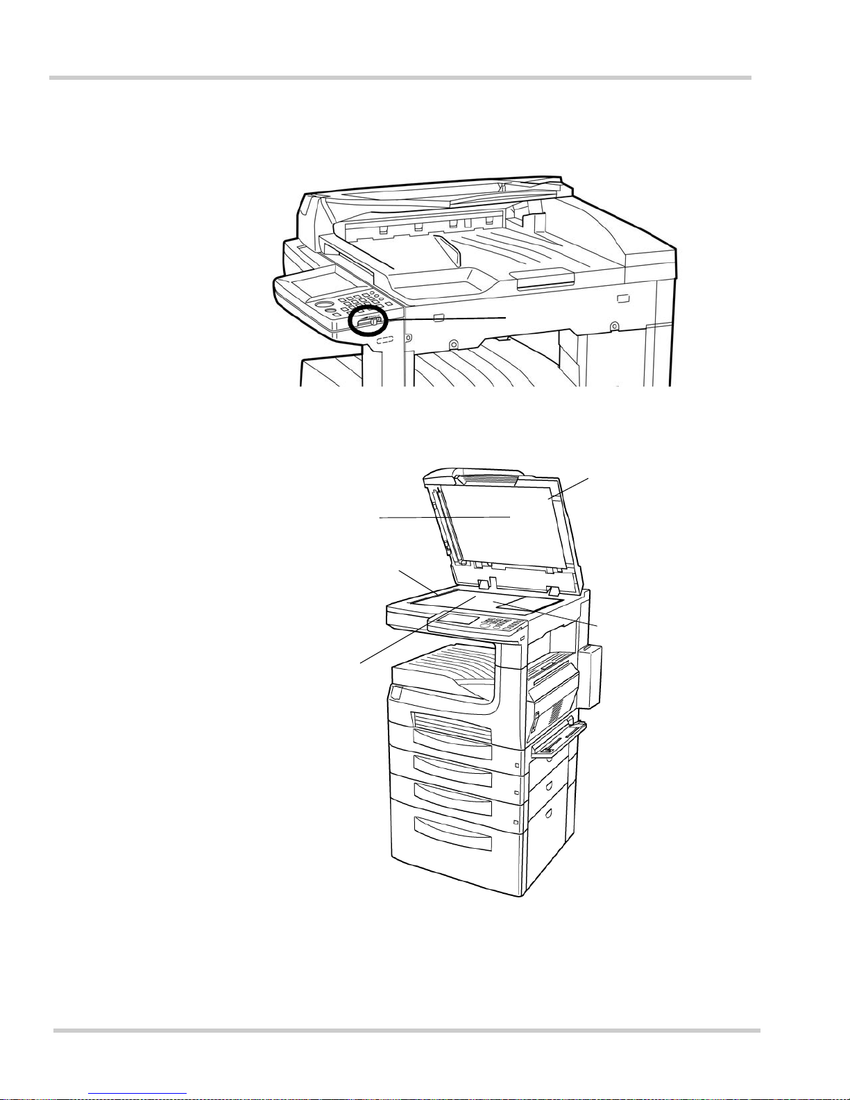
1 - 4 Gett ing Star t ed
Issue 1 NEC IT Series
Figure 1-2 Location of the Brightness Control
Brigh tness Control
Figure 1-3 Open Document Cover
Document Pad
Document Scanning
Area
Book Scanner
With the document
cover opened, a
docu me nt or book is
place d on th e glass
surface in order to be
transmitted or co pied
Document Cover
Glass Surface
Page 49
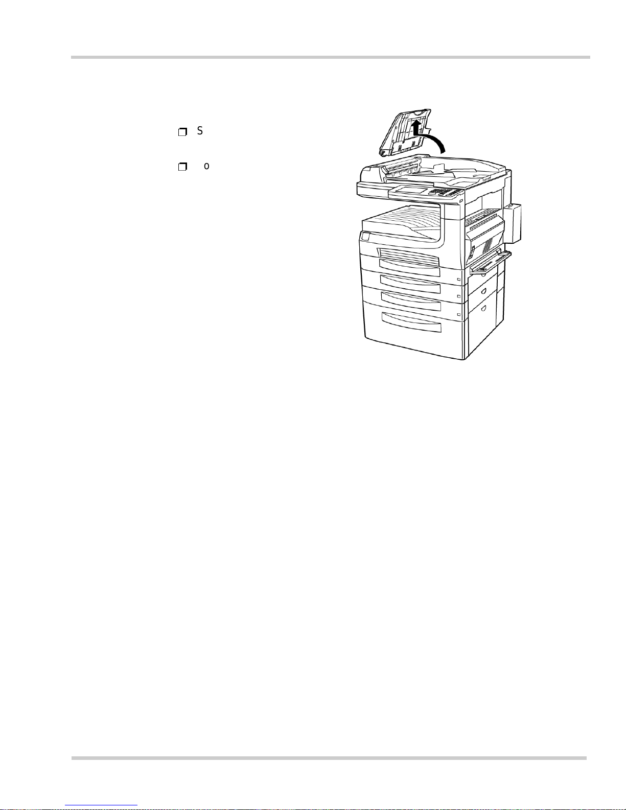
NEC IT Series Issue 1
NEC IT3510/IT2510 Operations Manual 1 - 5
Figure 1-4 Detaching the Document Feed Tray
Ë
Swing the tray upright before
lifting up to remove it.
Ë
Follow the s ame procedure in
reverse to reattach the tray.
Page 50
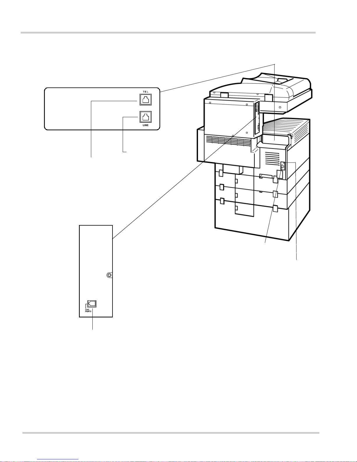
1 - 6 Gett ing Star t ed
Issue 1 NEC IT Series
Figure 1-5 Back View of the NEFAX IT3510
Power Inlet
Ground Terminal
•
Standard Machine
Connector for an
extra telephone set
Line Connector
(for fax line)
•
For Optional 2nd G3 Port
Before connecting an extra telephone set, check
that it can be used on the type of telepho ne line
installed. Some types of telephones may be
unusable. For details, contact your service
agent or dealer.
Second G3 Line
Connector (for fax line)
Page 51
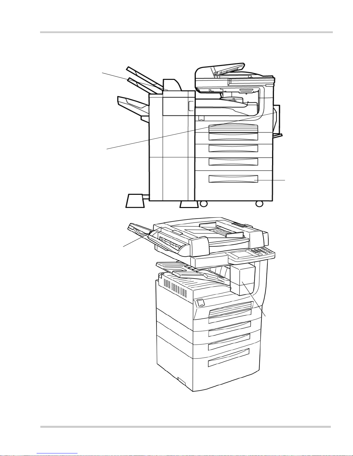
NEC IT Series Issue 1
NEC IT3510/IT2510 Operations Manual 1 - 7
Figure 1-6 Optional Equipment for Additional Efficiency
Multi-staple Finisher/
Single-staple
Finisher/Mail-bin
Finisher
• Printed pages from facsimile,
printer, or copier are
automatically sorted
• Doc uments can be s tapled
and/or hole-punched (with a
Multi - staple Finish er, as
shown)
2-Sided Print Unit
Allow s print ing on both s ides o f
paper
Large
Capacity
Cabinet
Up to 2500 sheets
of print paper
capacity
2-Sided Document Feeder
Both sides of a document can be
copied or transmitted
Job Tray/Shift
Tray
Documents from the
copier, printer, or
facsimile are
automati ca ll y sorted
(Job Tray is shown)
Page 52
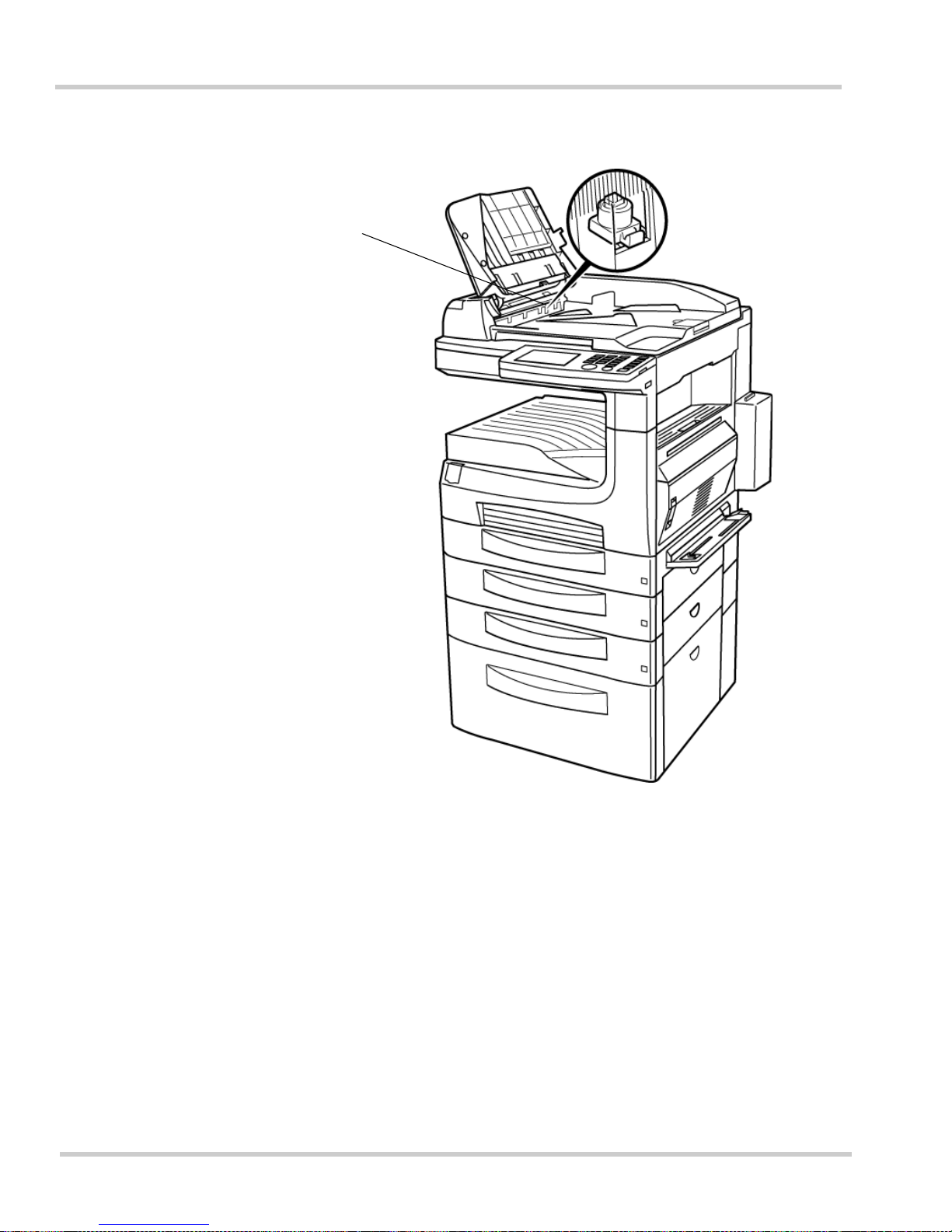
1 - 8 Gett ing Star t ed
Issue 1 NEC IT Series
Figure 1-7 TX Marker Location
TX Marker
Marks each sheet,
confirm ing th at it has
successfully been
scanned
Page 53
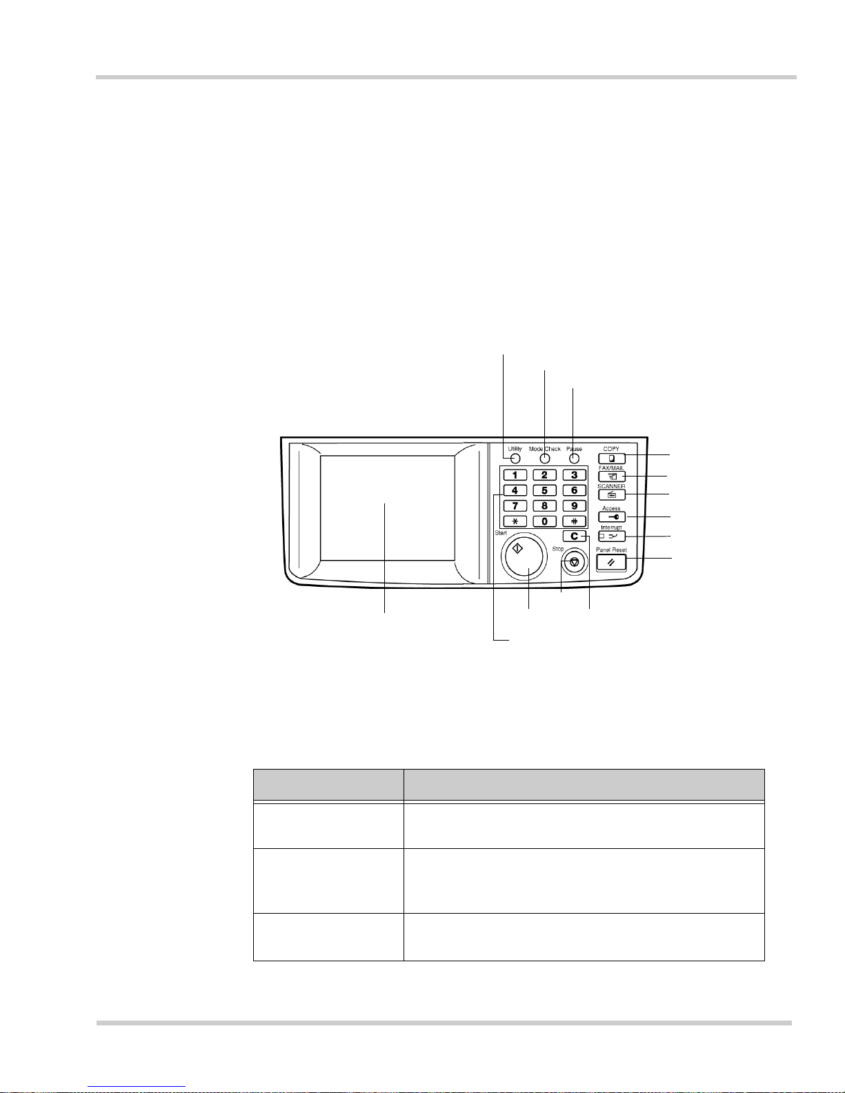
NEC IT Series Issue 1
NEC IT3510/IT2510 Operations Manual 1 - 9
SECTION 3OPERATION PANEL AND TOUCH PANEL
3.1 Operation Panel
The Operation Panel is used for entering information into the unit and for
machine operation. The Touch Panel allows the operator to easily and
efficiently register data into the unit.
Figure 1-8 Operations Panel Components
Key Name Function
COPY
Press this key to copy. When this lamp is lit, the
copy functions are av ailable.
FAX/MAIL
Press t his key t o send a facsimi le or e-mail. When
this lamp is lit, the facsimile or e-mail functions are
available for use.
SCANNER
Press t his key t o use the sc anner function.
(Net w ork option is required for s c anner function)
Touch Panel
Utility
Mode Check
Pause
FAX/MAIL
COPY
Access
Interrupt
Panel Reset
Clear
Stop
Start
10-key Pad
SCANNER
Page 54
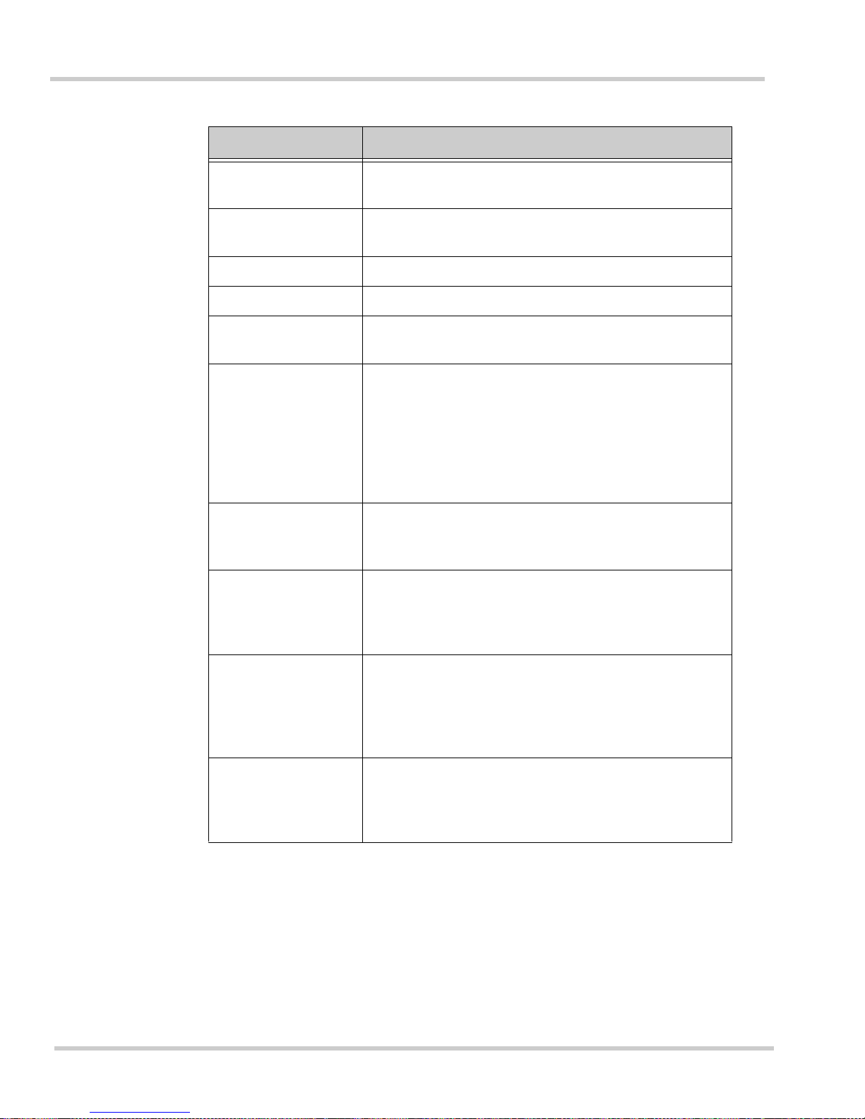
1 - 10 Gett ing Star t ed
Issue 1 NEC IT Series
Access
Press this key to enable the user management
mode.
Interrupt
Press this key to interrupt an operation in progress.
The lamp will stay lit during the interrupt process.
Panel Reset Press this key to reset the touch panel settings.
Utility Press this key for registratio n and to make settings.
Mode Check
Press this key to confirm the setting status of each
function.
Pause
Press this key to insert a preset pause of three
seconds when dialing a telephone number. A
pause is needed, in certain cases, to enter
additional numbers such as account numbers,
passwords , et c . The pause key can also be used
when registering One-Touch and Abbreviated
dialing key s.
10-key Pa d
Press these keys to enter a facsimile telephone
number, number of copies desired, or other data to
be registered.
C (Clear)
Pressing this key will reset the number of copies
entered to "1". Pressing this key will also clear any
data entere d w hen dialing a num ber or re gistering
information.
Start
Press this key to begin copying, transmission of a
facsimile, or reception of a facsimile after talking
(manual re c eptio n). Copy and transmission are
avail abl e whi le th e lamp is green. When the l amp is
oran ge, cop ying an d tran smiss ion are not avai labl e.
Stop
Press this key to stop an operation, such as
transmission or copying. T his is not t he same as
using the interrupt key, which temporarily suspends
an operation.
Key Name Function
Page 55
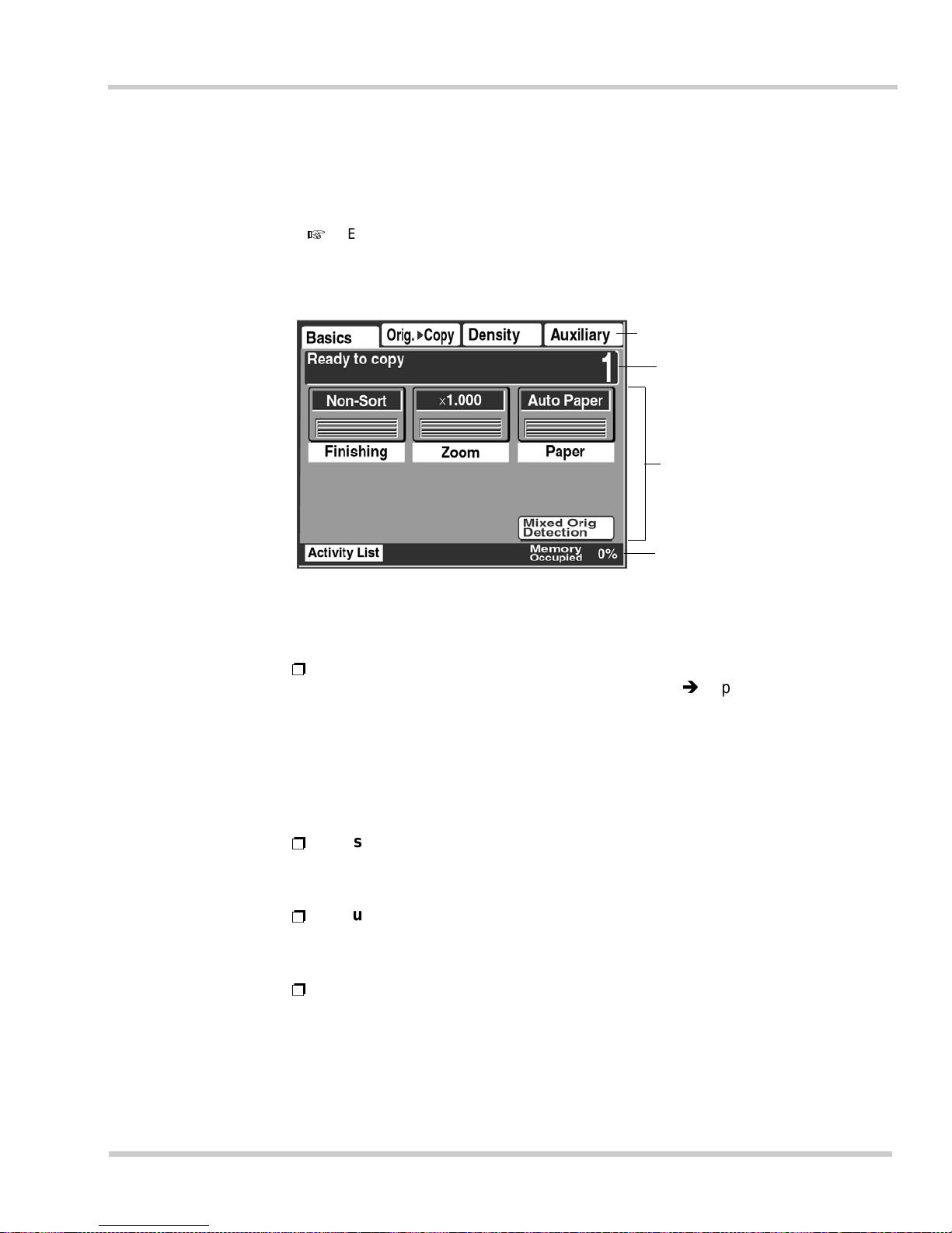
NEC IT Series Issue 1
NEC IT3510/IT2510 Operations Manual 1 - 11
3.2 Touch Panel
The Touch Panel is used to specif y the functio ns of the copier a nd facsimi le,
as well as to register information for various functions.
Examples of touch panel screens shown in this manual may differ slightly from the
actual display due to software modifications.
Figure 1-9 Touch Panel Display
Supplementary Function Keys
Message zone
Keys
Status and Alarm zone
Ë
Keys / Function Tabs
Keys and tabs, such as [Density] and [Orig.Copy], are used to
select operations. By touching different keys and tabs copy and
facsimile function s and re gistrati on menus can be se lected . One ty pe
of key cha nges the actual s creen when touch ed, while anothe r type
selects a d esired function. In th e latter case, the ke y changes from
normal (d ark letters on a wh ite backgr ound) to i nverted (w hite letter s
on a dark background) when touched.
Ë
Message
The mess ag e area furt he r explain s an ope ra tio na l proc ed ur e, suc h as
[Rea dy to copy].
Ë
Status Display zone
This area displays icons in dicating the volum e of memory use d and
the equipment status.
Ë
Alarm Display zone
This area displays icons warning the user of machine problems such
as no print paper install ed, a paper j a m , or a communication error, etc.
Page 56
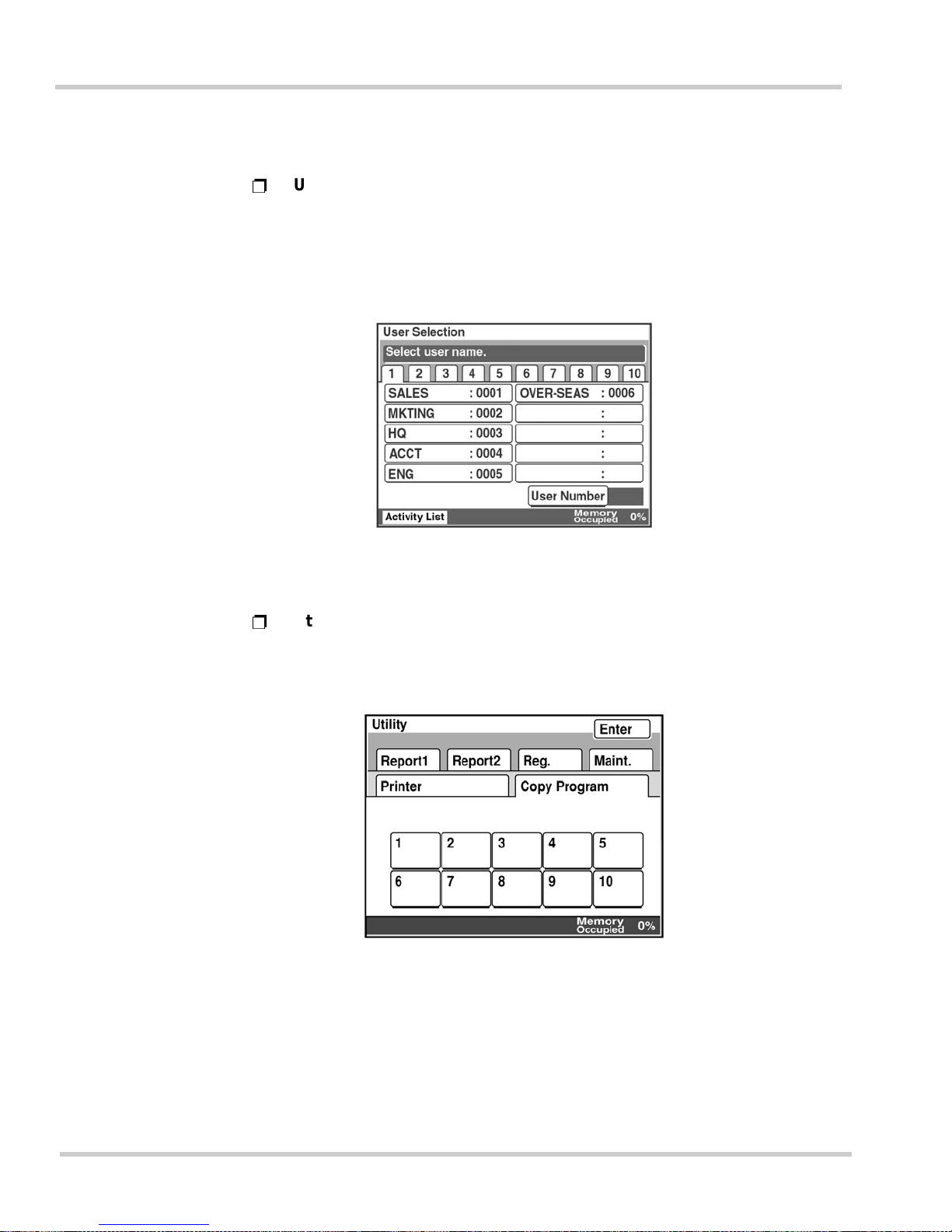
1 - 12 Gett ing Star t ed
Issue 1 NEC IT Series
Details of the Main Screens
Ë
User Se le ction Screen
This screen i s displ ayed whe n the Manageme nt Mode has been enabled
and is used to track machine usage by an individual person or
department. The operator must select their registered name or
department before using the machine.
Ë
Utility Screen
This screen is used to set various options, register items such as
facsimile numbers, date and time, etc., and to print reports.
Figure 1-10 User Selection Screen
Figure 1-11 Utility Screen
Page 57
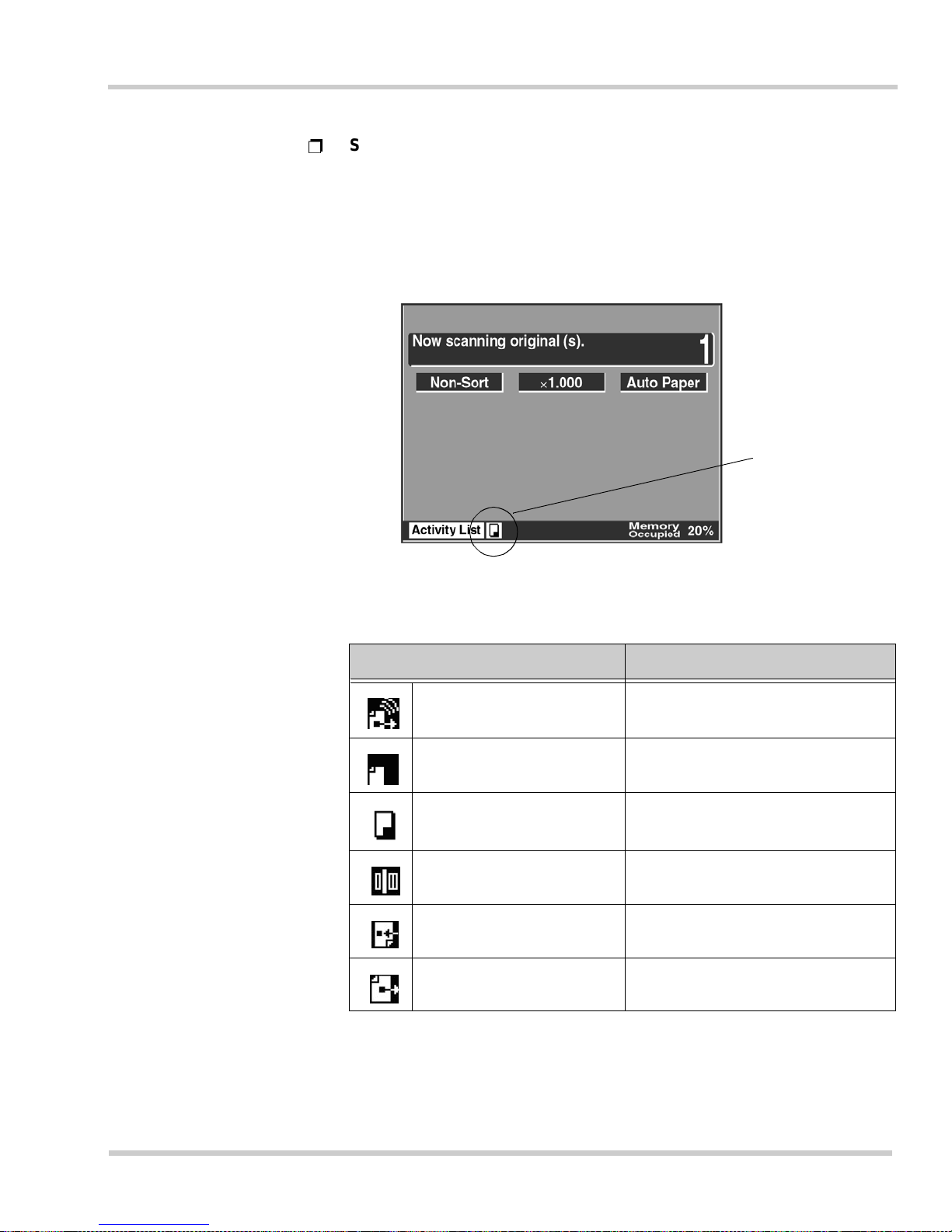
NEC IT Series Issue 1
NEC IT35 10/ I T 2510 Operations Ma nual 1 - 13
Ë
Status Display
While the unit is performing an operation, its status is indicated by icons
located at the bottom of the touch panel. Refer to Figure 1-12 Status
Display. Table 1-1 Standard Icons shows the icons displayed during
normal machine oper ation. For a co mplete list of i cons used, re fer to
Section 1.1 Display Icons in Chapter 8 Troubleshooting on page 8-1.
Figure 1-12 Status Display
Table 1-1 Standard Icons
Icons Description
Dialing Now diali ng a des t ination
Dial Wait Waiting to redial a destination
Copyin g Now copy ing
Scanning Now scanning a facsimile page
Receiving Now receiving a facsimile
Sending Now sending a facsimile
Icon zone
Page 58

1 - 14 Gett ing Star t ed
Issue 1 NEC IT Series
Automatic Display Time-out
If a selected screen, such as a menu screen, is left open the touch panel
automatically returns to the initial screen after a user-set time period. For
details on setting this time-out period, refer to Section 2.6 Power Saving
Settings in Chapter 4 Advanced Registration and Setting Operations on page
4-30.
Either the facsimile screen or the copier screen can be set as the default
display. For details on set ting the de fault disp lay, refer to Sectio n 2.8 S etting
the Initial Screen to Display (Priority Screen) in Chapter 3 Registration and
Setting Operations on page 3-22.
Automatic Backlight
The touch pa nel automatical ly turns off to sa ve power and conserv e screen
life. To enable the panel backlight, simply touch anywhere on the panel
surface. The panel backlight time-out can be set by the user. Refer to Section
2.6 Power Saving Settings in Chapter 4 Advanced Registration and Setting
Operations on page 4-30 for more details.
3.3 Stand-by Screen (Initial Screen)
The screen which is displayed when the equipment is ready to begin
operations for copying, facsimile activity, and registration, is called the
standby screen. The stand-by screen can be set from three types to suit the
way you normally use the machine.
The three stand-by screen choices are:
Ë
Auto-mode Screen (default screen set at factory)
Ë
Copy Screen
Ë
Facsimile Screen
For details on setting the stand-by screen, refer to Section 2.8 Setting the
Initial Screen to Display (Priority Screen) in Chapter 3 Registration and Setting
Operations on page 3-22.
Auto-mode Screen
This scre en is used f or both facsim ile and copy oper ations without spec ifying
which func tion is used .
Page 59
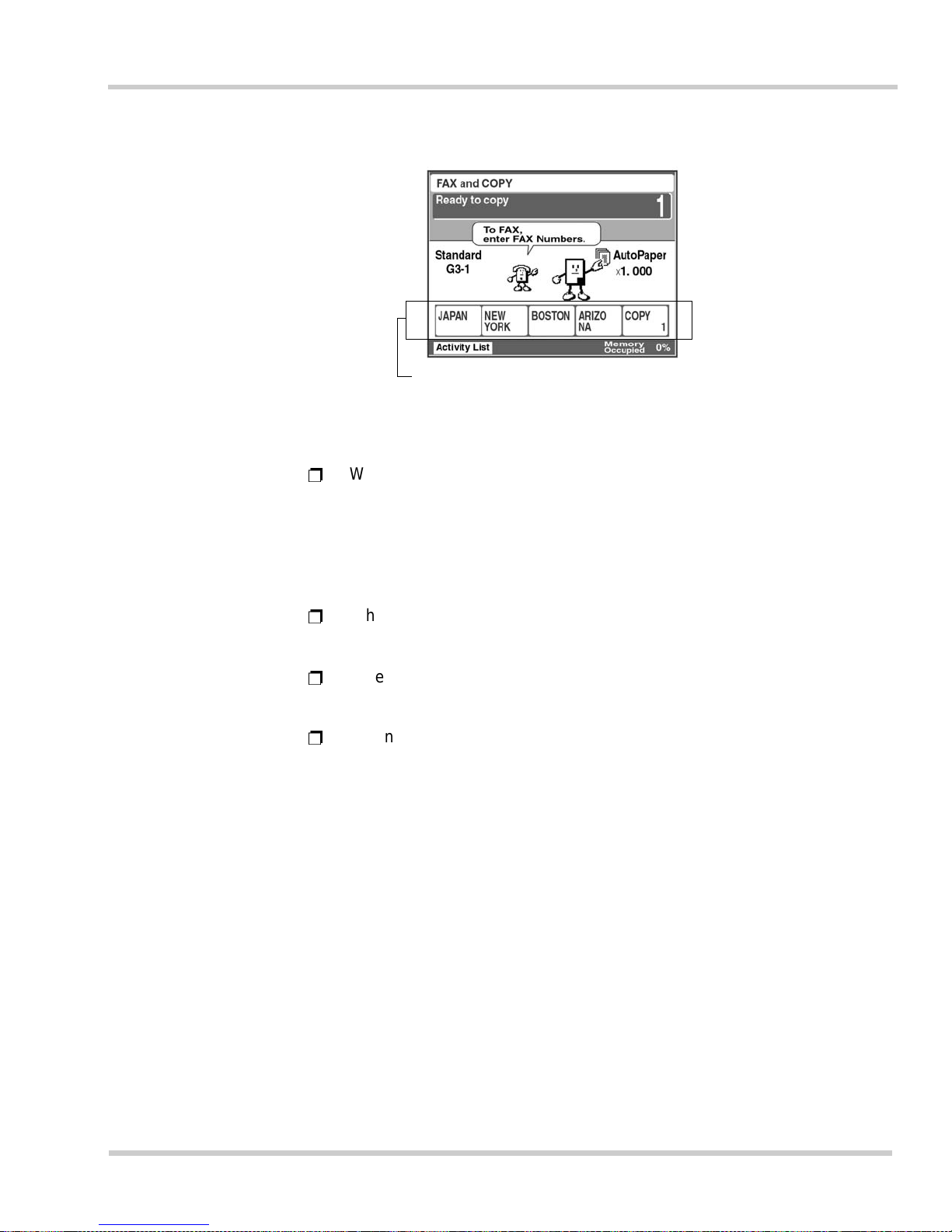
NEC IT Series Issue 1
NEC IT35 10/ I T 2510 Operations Ma nual 1 - 15
Ë
When the 10-key Pad is used to enter a figure of four digits or more
(three digits for the IT2510), or a figure starting with ’0’, and <Start> is
pressed, the equipment automatically determines it to be a facsimile
number an d begin s transmissio n. When a three-digit number or less (a
two-digit number for the IT2510) is entered, the equipment determines
this the number of copies required and begins copying.
Ë
When <COPY> is pressed, the copy menu screen is displayed. To
select the copy function, press the <COPY> key.
Ë
When <FAX> is pressed, the facsimile menu screen is displayed. To
select the facsimile function, press the <FAX> key.
Ë
When t he Auto-mode screen ha s been selec ted as the d efault screen,
pressing the <Panel Reset> key twice, while in the copy or facsimile
menu screens, will return you to the Auto-mode screen.
Figure 1-13 Auto-mode Screen
Facsi mi le numbers registered for One-Touch keys
1~4 and copy program key 1 are displayed in this
zone.
Page 60
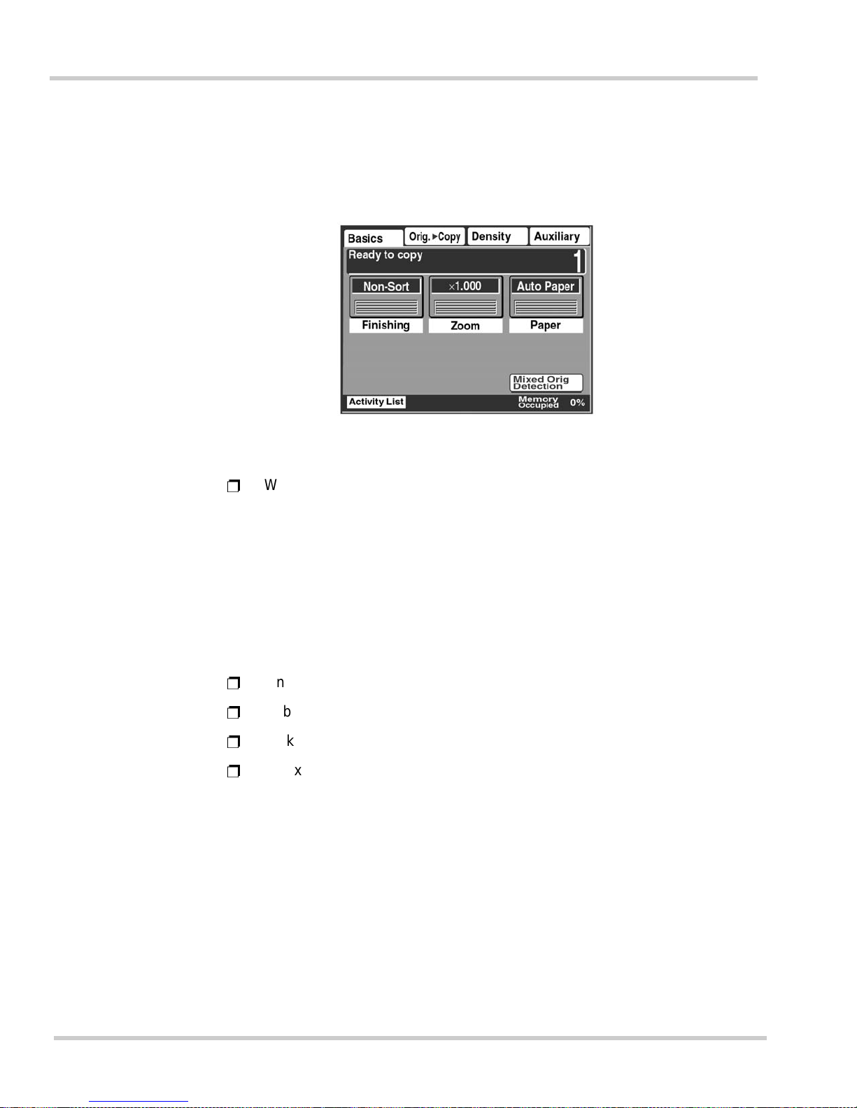
1 - 16 Gett ing Star t ed
Issue 1 NEC IT Series
Copy Screen
This scree n is used to select va rious copying functions. If this equ ipment is
mainly used as a copier, this screen can be set as the default stand-by screen.
Ë
When <F AX> is pressed on the operation panel, the facsimile menu
screen is displayed. To select the various facsimile functions, press the
<FAX> key.
FA X Screen
This screen is used to select the facsimile functions. If this equipment is used
mainly as a facsimile unit, it may be convenient to set this screen as the
defau l t stan d-b y sc re en. The fac si mil e numbe r se le ct ion s creen d is p lay ed f i rst
can be selected from the following:
Ë
One-Touch numbers screen (factory default screen)
Ë
Abbreviated numbers screen
Ë
10-key Dialing screen
Ë
Index List screen
For details on changing the default screen, refer to Section 2.9 Setting the
Priority Facsimile Screen in Chapter 3 Registration and Setting Operations on
page 3-24.
Figure 1-14 Copy Screen
Page 61
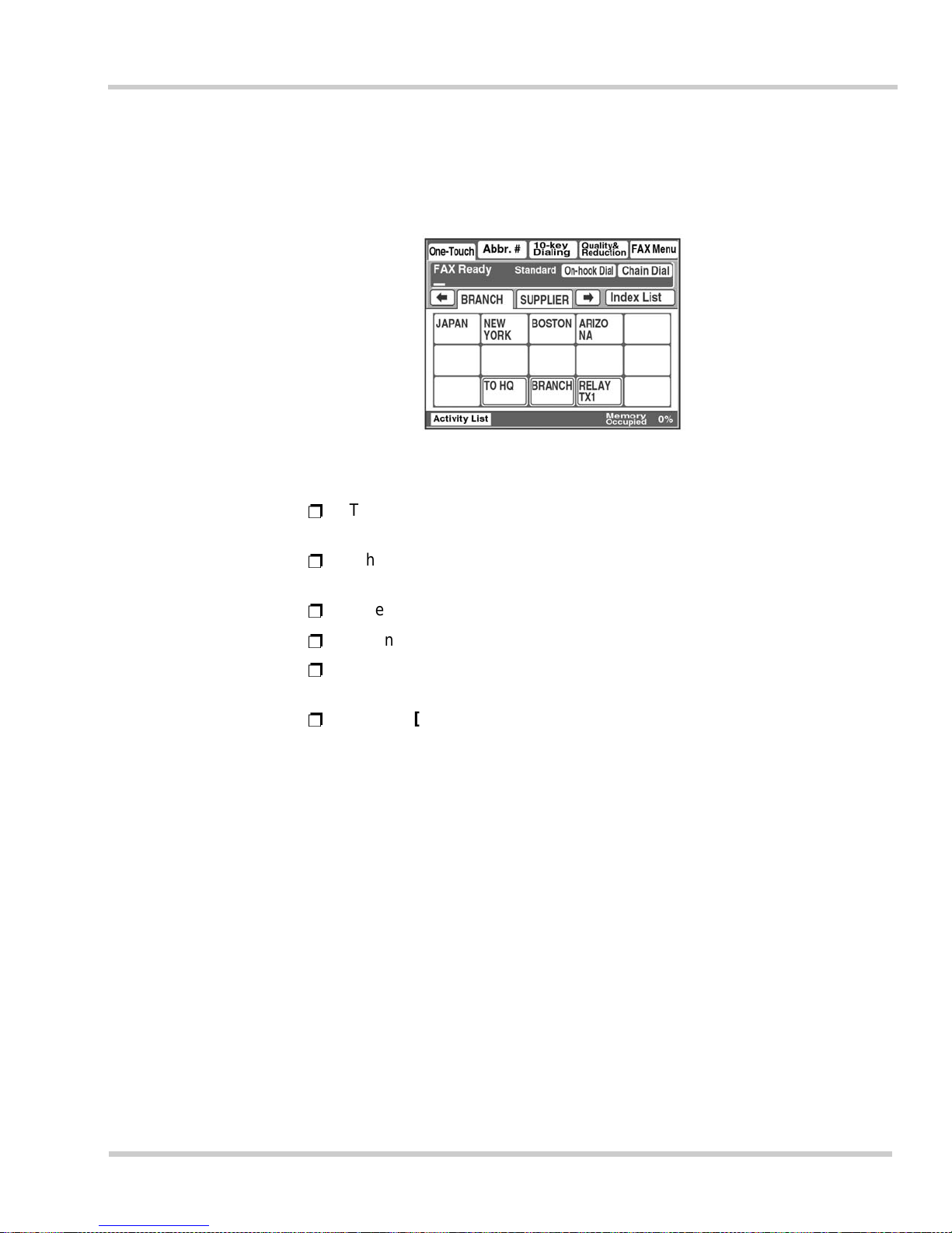
NEC IT Series Issue 1
NEC IT35 10/ I T 2510 Operations Ma nual 1 - 17
One-Touch Screen
This screen displays numbers that have been registered in advance for
One-Touch dialing.
Ë
There are 20 One-Touch screens in total, and up to 300 numbers can be
registered (15 numbers per screen x 20 screens = 300 numbers total).
Ë
When <COPY> on the operation panel is pressed, the copy menu is
displayed. Press <COPY> to select the copy function.
Ë
When [Abbr.#] is touched, the abbreviated dialing screen is displayed.
Ë
When [10-key Dialing] is touched, the dial input screen is displayed.
Ë
When [Quality & Reduction] is touched, the facsimile transmission
image qua lity, contr ast, and re duction screen is displaye d.
Ë
When [FAX Menu] is touched, the screen setting various
communications parameters is displayed.
Figure 1-15 One-Touch Screen
Page 62
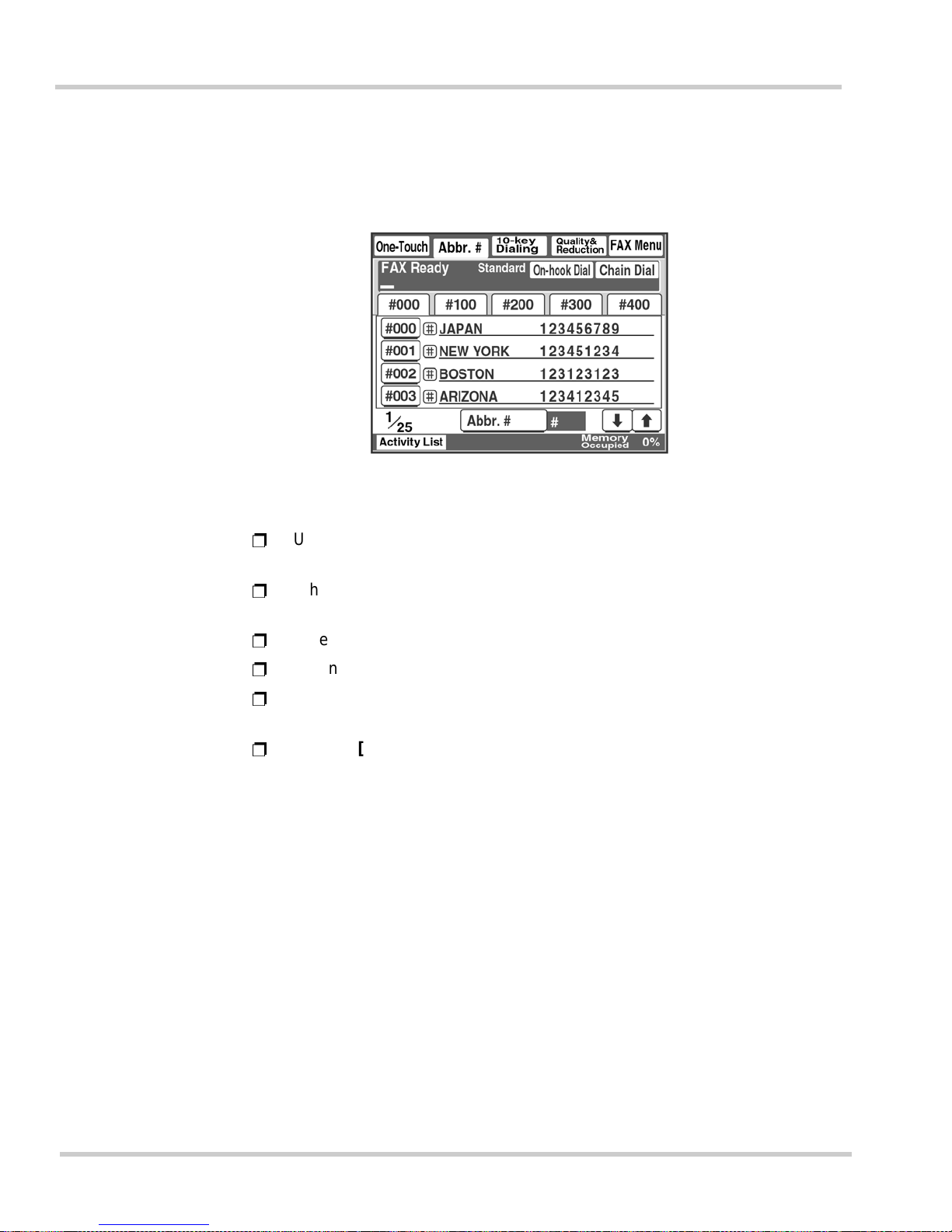
1 - 18 Gett ing Star t ed
Issue 1 NEC IT Series
Abbreviated Diali n g Scr een
This screen displays the facsimile numbers, registered in advance, that are
set as abbrev iated dia ling numbers.
Ë
Up to 500 numbers can be registered (including 300 One-Touch dial
destinations).
Ë
When <COPY> on the operation panel is pressed, the copy menu is
displayed. Press <COPY> to select the copy function.
Ë
When [One-Touch] is touched, the One-Touch screen is displayed.
Ë
When [10-key Dialing] is touched, the dial input screen is displayed.
Ë
When [Quality & Reduction] is touched, the facsimile transmission
image qua lity, contr ast, and re duction screen is displaye d.
Ë
When [FAX Menu] is touched, the screen setting various
communications parameters is displayed.
Figure 1-16 Abbreviated Dialing Screen
Page 63
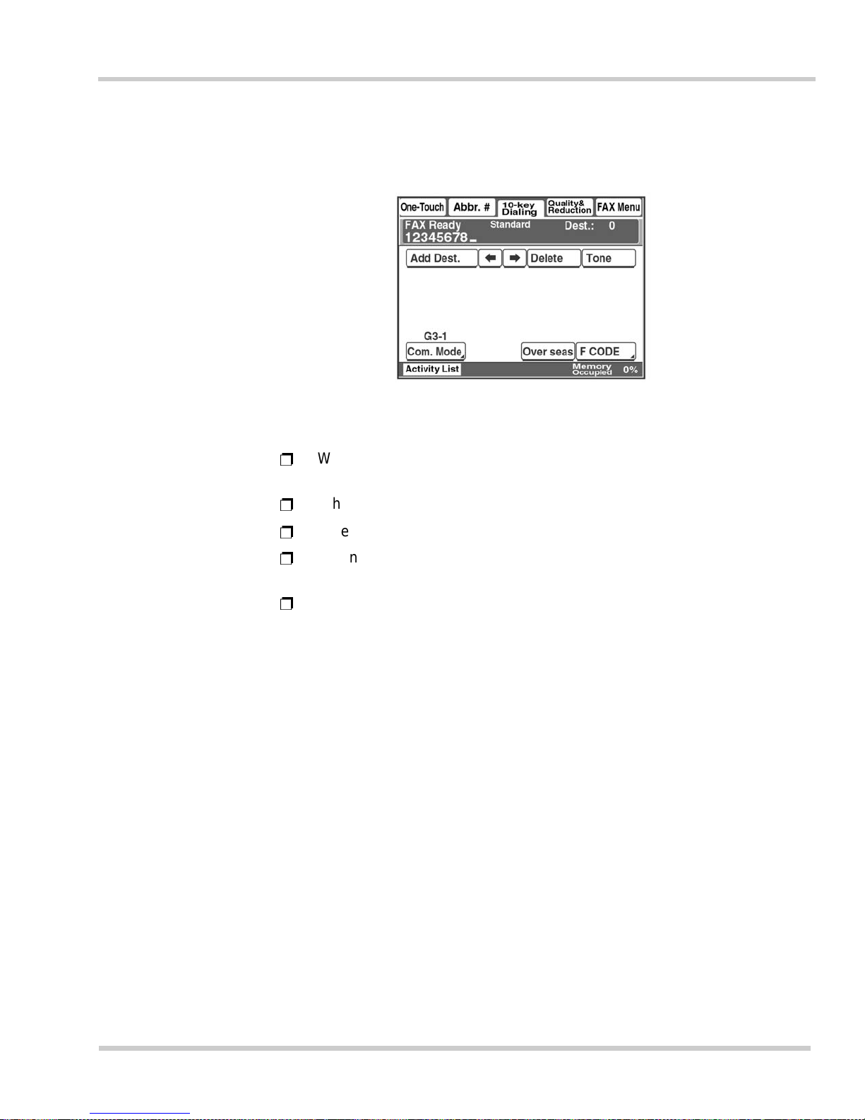
NEC IT Series Issue 1
NEC IT35 10/ I T 2510 Operations Ma nual 1 - 19
10-key Dialing Screen
Use this screen to enter a facsimile number by using the 10-key dialing pad.
Ë
When <COPY> on the operation panel is pressed, the copy menu is
displayed. Press <COPY> to select the copy function.
Ë
When [One-Touch] is touched, the One-Touch screen is displayed.
Ë
When [Abbr.#] is touched, the abbreviated dialing screen is displayed.
Ë
When [Quality & Reduction] is touched, the facsimile transmission
image qua lity, contr ast, and re duction screen is displaye d.
Ë
When [FAX Menu] is touched, the screen setting various
communications parameters is displayed.
Figure 1-17 10-key Dialing Screen
Page 64
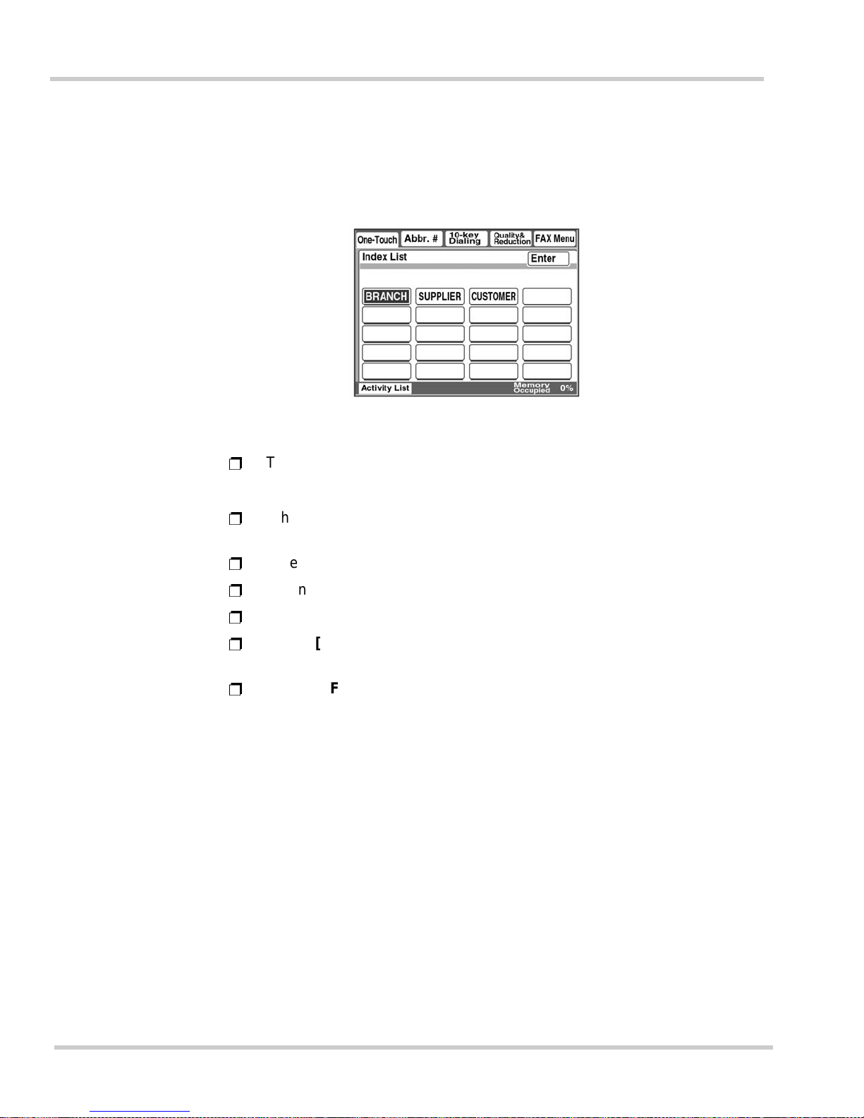
1 - 20 Gett ing Star t ed
Issue 1 NEC IT Series
Index List Screen
This screen displays an index list for classifying the One-Touch keys. The
Index List makes for a c onvenient w ay to organiz e the previous ly registered
One-Touc h key s into handy categori e s or titles.
Ë
There a re 20 ind ex keys in total, and up to 15 One-Touch keys can be
registe red per index key.
Ë
When <COPY> on the operation panel is pressed, the copy menu is
displayed. Press <COPY> to select the copy function.
Ë
When [Enter] is touched, the One-Touch screen is displayed.
Ë
When [Abbr.#] is touched, the abbreviated dialing screen is displayed.
Ë
When [10-key Dialing] is touched, the dial input screen is displayed.
Ë
When [Quality & Reduction] is touched, the facsimile transmission
image qua lity, contr ast, and re duction screen is displaye d.
Ë
When [FAX Menu] is touched, the screen setting various
communications parameters is displayed.
Figure 1-18 Index List Screen
Page 65
NEC IT Series Issue 1
NEC IT35 10/ I T 2510 Operations Ma nual 1 - 21
3.4 Users and User Management Mode
Different settings can be saved for each user of the machine. Users are
defined as individual persons using the unit, or users can be separate
departments using the machine. Unauthorized machine usage is prevented
by pre-registering approved us ers .
Users:
Those persons who are registered in the IT3510/IT2510 are called Users. Users can
use the mailbox or any other function that have been specified for the user, once they
are registered. Refer to Section 2.15 Registering Users in Chapter 3 Registration and
Setting Operations on page 3-37.
Users are registered using the Administrator Management screen. Refer to Section
2.2 Accessing the Administrator Management Screen in Chapter 3 Registration and
Setting Operations on page 3-12.
Registered user data can be amended by the users. Refer to Section 2.8 Amending
User Data in Chapter 4 Advanced Registration and Setting Operations on page 4-35.
User Management Mode:
The usage status for each user can be confirmed. Unauthorized use of the machine
can be prevented by registering a password for each user. Refer to Section 2.7
Confirming the Usage Status of Each User in Chapter 4 Advanced Registration and
Setting Operations on page 4-34.
Ë
When U sers are to be Restr ic ted:
Registration / Settings Before Use Operation When Used
User
Management
Mode
User
Registration
Password
Registration
User Selection
Operation
Password
Input
When users
are restricted
by passwords
Limited Required Yes Required Required
When users
are not
restricted by
passwords
Limited Required No Required
Not
Required
Page 66
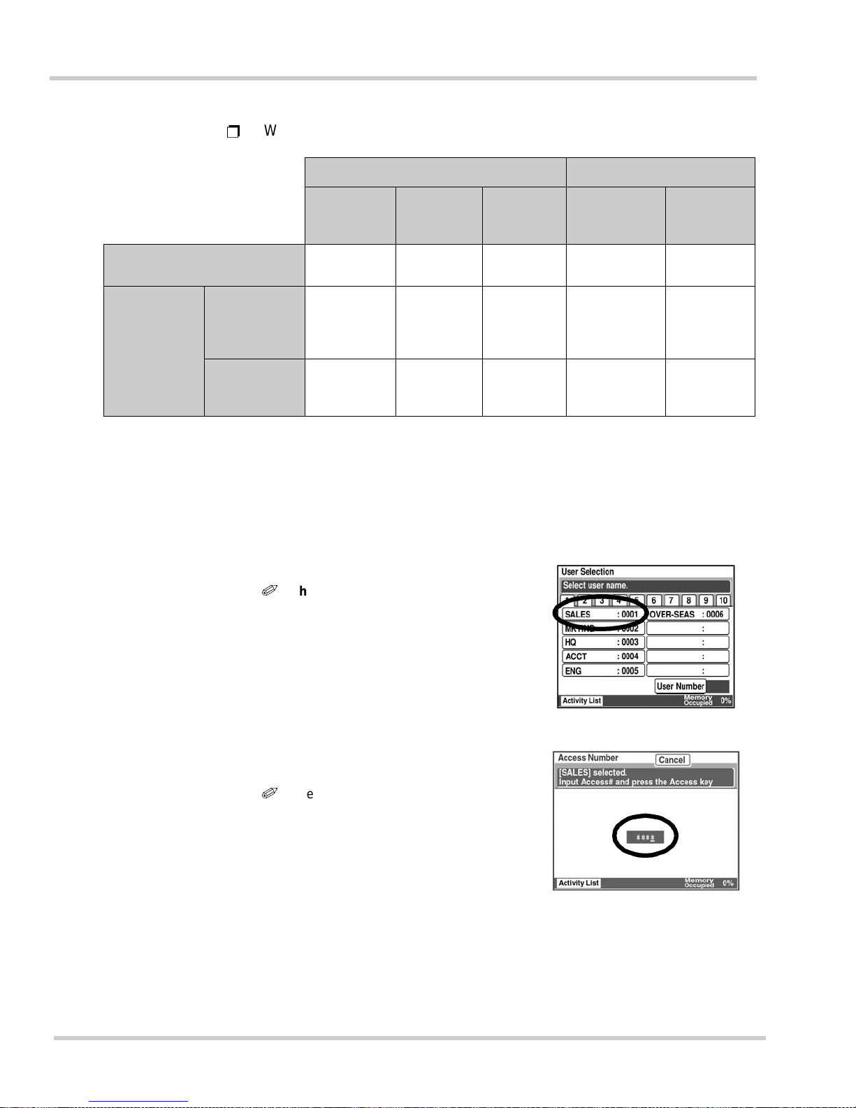
1 - 22 Gett ing Star t ed
Issue 1 NEC IT Series
Ë
When U sers are Not Res tric ted :
Registration / Settings Before Use Operation When Used
User
Management
Mode
User
Registration
Password
Registration
User Selection
Operation
Password
Input
When used with common
settings
Open
Not
Required
— N ot Required
Not
Required
When used
with individual
settings
When users
are not
restricted by
passwords
Open Required No Required
Not
Required
When users
are restricted
by passwords
Open Required Yes Required Required
User Selection
1.
Press <Access>.
2.
Select the Us er.
i
When specified by User
Number:
Touch [Us er Number] and use the 10key Pad t o en ter th e num b er.
3.
Use th e 10-key Pad to ent er the
Access Number (four digits).
i
When no access number is
registered, the stand-by sc reen is
displayed instead.
4. Press <Access>. The stand-by
screen is now displayed.
Page 67

NEC IT Series Issue 1
NEC IT35 10/ I T 2510 Operations Ma nual 1 - 23
Ë
After Completing Copying or Transmission:
When users are restricted, <Access> mu s t be pr es sed once t he t a sk i s
completed. This prevents unauthorized usage after the current
operation is finished.
When <Access> is press ed, all se t t ings f or copy and facsim ile fun c t i ons
are reset, and the display returns to the user selection screen.
Page 68
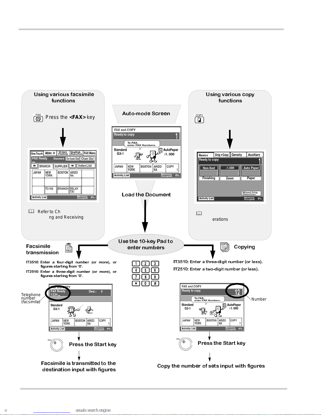
1 - 24 Gett ing Star t ed
Issue 1 NEC IT Series
S
ECTION
4HOW TO
USE THE COPIER AND FACSIMILE
(A
UTO-MODE SCREEN
)
The Auto-mode screen can be switched between setting the number of copies
needed and the facsimile destination by simply entering the appropriate numbers.
When th is Auto-m ode s cre en is disp laye d, the product can be used without selecting
the copy or facsimile screens.
Using various facsimile
functions
Press the <FAX> key
Auto-mode Screen
Refer to Chapter 5 Basic
Sending and Receiving
Operations
Load the Document
Using various copy
functions
Press the <COPY> key
Refer to Chapter 2 Copy
Operations
Use the 10-key Pad to
enter numbers
IT3510: Enter a four-digit number (or more), or
figures starting from ’0’.
IT2510: Enter a three-digit number (or more), or
figures starting from ’0’.
IT3510: Enter a three-digit number (or less).
IT2510: Enter a two-digit number (orless).
Facsimile
transmission
Copying
Telephone
number
(facsimile)
Number o
f
sets to b
e
copied
Press the Start key
Press the Start key
Facsimile is transmitted to the
destination input with figures
Copy the number of sets input with figures
Page 69
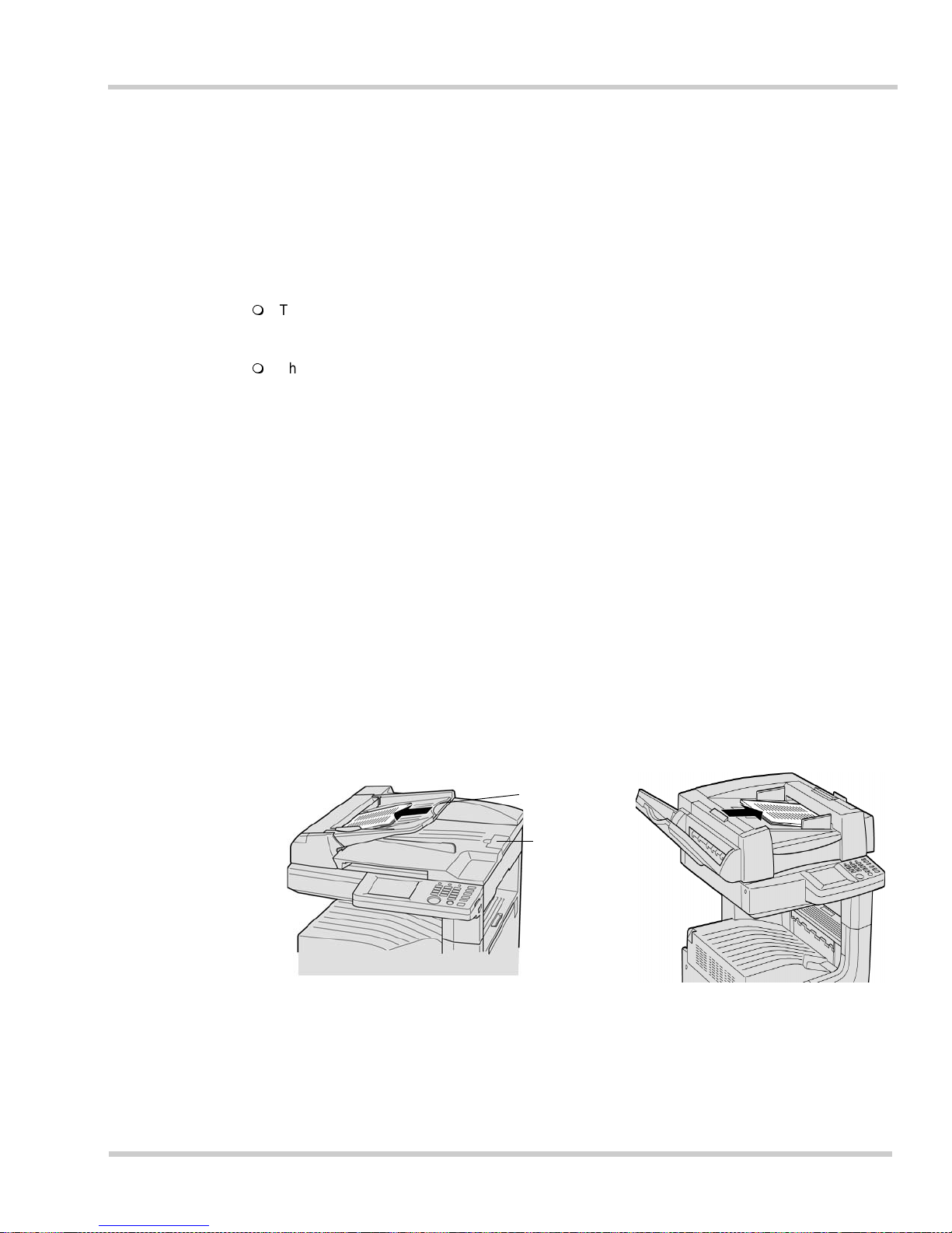
NEC IT Series Issue 1
NEC IT35 10/ I T 2510 Operations Ma nual 1 - 25
SECTION 5HANDLING DOCUMENTS
This s ec tion p rovid es infor m ation on co rrectl y handling documents for transmission or
copying. Document pages may be inserted in two different ways. For additional
details, refer to Section 5.4 Notes on Handling Documents on page 1-27.
Before Starting Operations:
The Automatic Document Feeder (ADF) feeds document pages one-by-one, when transmitting
and copying. Pages are away placed information side up, will scan from the top page down,
and will exit the ADF in their original order.
The Book Scanner is used when transmitting or copying documents that cannot be handled by
the ADF, such as books, catalogs, and bound materials.
5.1 Using the Au to matic D o cu ment Feeder (A D F )
1. Place the d ocument face up at the le ft side of the Do cument Fe ed Tray.
The right side is us ed for t he 2-Si ded Document Feeder.
2. Position the document firmly against the left of the document hopper (right
for the 2-Sided Document Feeder) and adjust the Document Guide
Plate(s) to the width of the pages. For long documents, pull out the
Extension Guide an d lift the Stopp er to preve nt the pages from falling off
the feeder.
3. Insert the document pages gently until they reach their initial edge and
stop inside the feeder.
Figure 1-19 Loading the Automatic Document Feeder
Automatic Document Feeder
Place the docu m ent face up in the feeder.
2-Sided Document Feeder (op tional
)
Place the document face up in the feeder.
Extension
Guide
Stopper
Page 70
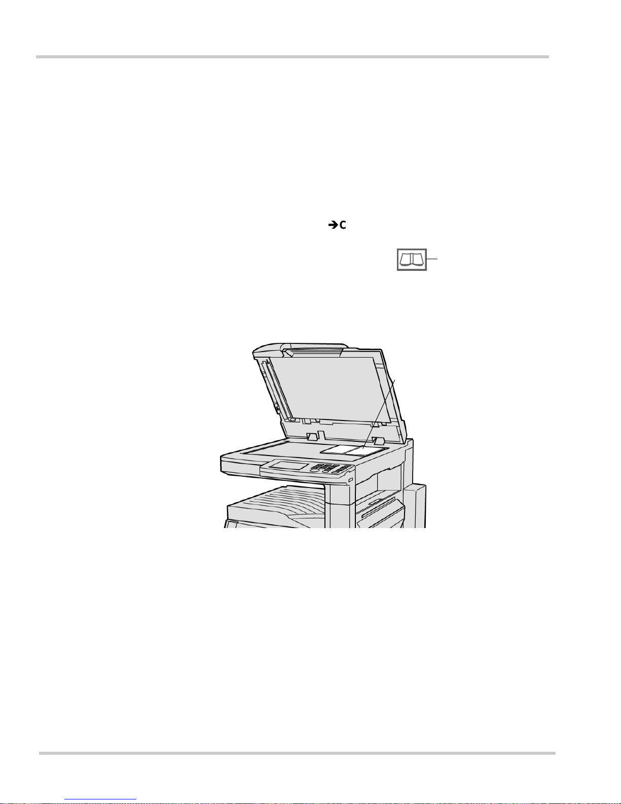
1 - 26 Gett ing Star t ed
Issue 1 NEC IT Series
5.2 Using the Book Scanner
1. Open the Docume nt Cover and pla ce the do cument face d own and flush
with the glass surface.
2. Position the docume n t in the top right-hand corner of the glass surface.
3. For transmission, the document should be placed with its longer side
against the back edge of the glass surface. If placed with the shorter side
against the back, the entire document may be reduced when transmitted.
4. When [Book] on the [Orig.Copy] is used, adjust the center of the
document to the mark on the Book Scanner.
5. Close the Document cover before beginning transmission or copying.
5.3 Using the Single Feed Tray
1. Open the Single Feed Tray.
2. Adjust the document guide to the width of the document.
3. Check that the green lamp on the <Start> key is lit.
4. Insert the document face down, so that it is flush with the edge of the
guide.
Figure 1-20 Using the Book Scanner
Bookscanner mark
Place the book, magazine, etc.
in the top right-hand corner
Page 71
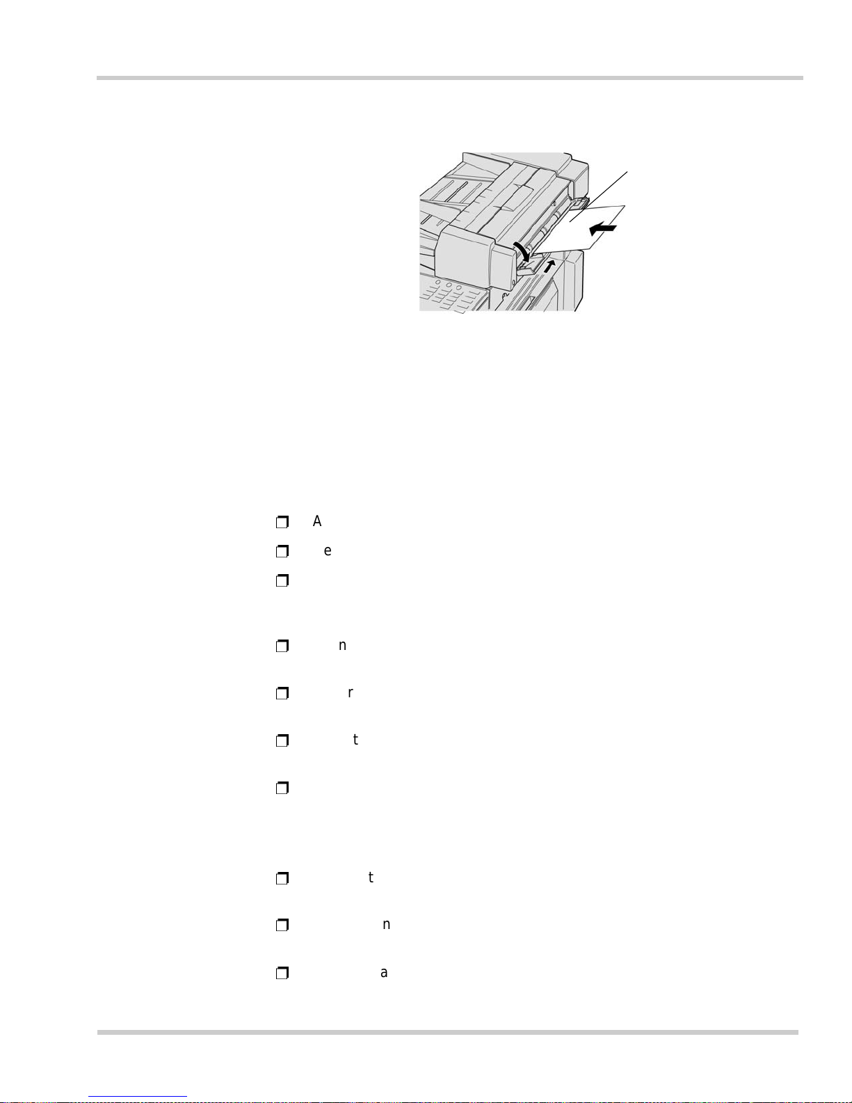
NEC IT Series Issue 1
NEC IT35 10/ I T 2510 Operations Ma nual 1 - 27
5.4 Notes on Handling Documents
Please observe these important points concerning h andling documents.
When Documents are placed in the ADF
Ë
Adjust the do cument guide plate(s) to the width of the document pages.
Ë
Remove all paper clips and staples f rom t he documents.
Ë
If a document has cut-and-paste or taped attachments, only the Book
Scanner should be used. Scanning these pages in the ADF may cause
a jam cond ition or affect the image quality.
Ë
Do not use the ADF for scanning pages containing tape flags, as this
may caus e a j am condition or affec t image quality.
Ë
Ensure that any correction fluid or ink has dried before inserting the
pages into the ADF.
Ë
Do not open the Document Feed Cover while the ADF is in use. This will
cause the ADF scanning operation to be suspended.
Ë
Ensure tha t no page s are l e ft on the B oo k Scanner gl ass. T he AD F will
not operate with a page left on the Book Scanner glass.
When Documents are placed on the Book Scanner
Ë
Ensure that any correction fluid or ink has dried before inserting the
pages on the glass surface.
Ë
When sca nning a book, or thick doc ument, do not force th e document
cover to close. Excessive force may cause damage to the doo r.
Ë
Ensure that no pages remain in the ADF. Th e Book Scanner will not
opera t e until these pages are rem oved.
Figure 1-21 Using the Single Feed Tray
Place the document to b e
transmitted or copied face
down in the feeder
• A document can also be placed in the 2Sided ADF in single sheet fashion
• The following functions cannot be used
when using the Single Feed Tray:
2-sided documents, 2-TO-1 function, Book
Scanner, Sorting, Grouping, Stapling, Cover
Sheets, Page Insertion, Distribution,
Copying with the Bypass Tray, Direction of
the Original, and Margin
Page 72

1 - 28 Gett ing Star t ed
Issue 1 NEC IT Series
Ë
Certain document sizes may not be automatically detected. In these
cases, the size must be manually selected. For detail s, refer to Se ction
2.12 Selecting the Scan Area in Chapter 5 Basic Sending and Receiving
Operations on page 5-18
.
Ë
Documents that may not be capable of automatic size detection:
Dark documents
Transparencies, such as over-head projector sheets and tracing
paper
Unusu ally shaped or l ong docu ments
Documents with raised (embossed) characters
Documents smalle r than Letter si ze ( portrait or landscape )
Documents larger than Ledger (11" by 17") size.
When used with the Document Cover open
Ë
If the paper being scanned is very thin, marks on the Document Cover
may affect image quality. In this case, place a blank sh eet of the same
size over the page to be scanned.
Ë
If the document is not a standard size (i.e., Letter or Legal) the machine
will choose the nearest standard size paper.
Ë
For correct page size detection to take place, the Document Co ver must
be opened to at least 15°.
Ë
Do not plac e any thi ng heavie r th an 6.6 lbs (3 kg) on the g l ass surface.
Ë
Avoid looking at the Book Scanning area when scanning takes place, as
a very bri ght light is used .
Ë
Use the Boo k Scan ner for copy ing or transm itting thin pa per (11 lbs) o r
excess iv ely t hic k paper (heavier than 22 lbs) .
Page 73
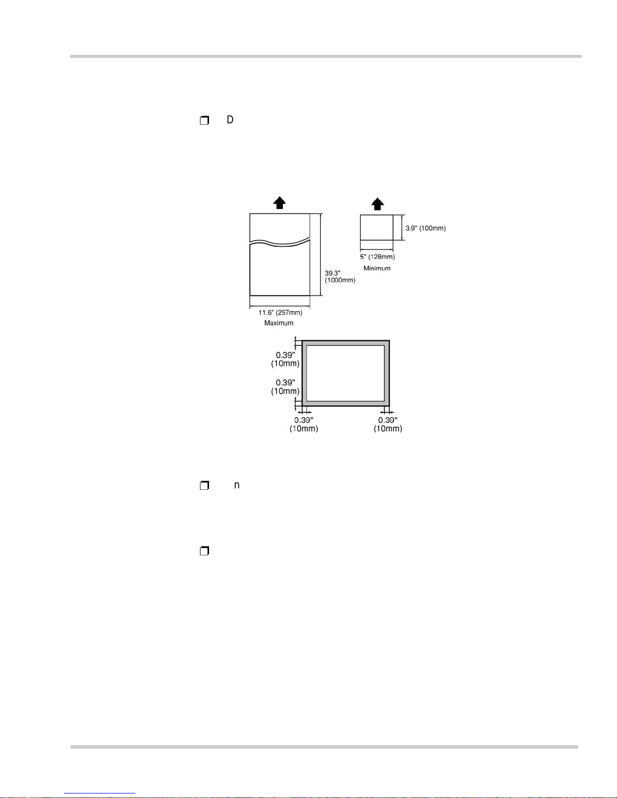
NEC IT Series Issue 1
NEC IT35 10/ I T 2510 Operations Ma nual 1 - 29
Maximum and Minimum Document Sizes
Ë
Docume nt sizes from 5" by 3.9" to 11.6" by 39.3" can be scanned when
using the ADF. If a document is of an irregular size, the size limits that
can be scanned are shown in Figure 1-22 Maximum and Minimum
Document Sizes.
Ë
Any size of up to Ledger (11" by 17") can be copied or transmitted using
the Book Sca nne r.
Maxim u m Num b er o f Pages in the ADF
Ë
Up to 70 pages can be loaded in the ADF at a time (or 50 pages when
the 2-Sided Document Feeder is used). Paper weights of between
14 lbs and 22 lbs may be used.
Figure 1-22 Maximum and Mini mum Document Sizes
The machine puts an outer margin
of 0.39" (10 mm) around the page
edge.
Page 74
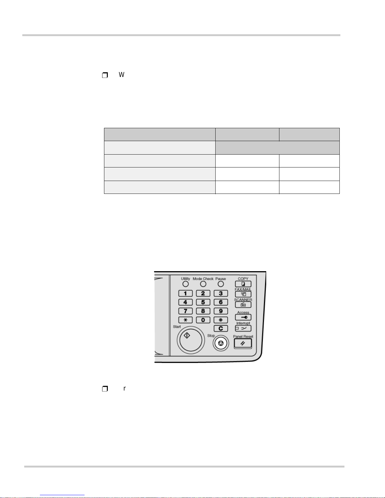
1 - 30 Gett ing Star t ed
Issue 1 NEC IT Series
T ra nsmitting Ledger sized Documents
Ë
When a Ledg er (11" by 17") docume nt is transmi tted, it is auto matica lly
reduced according to the paper sizes available in the receiving facsimile.
To send Ledger size pages in their original size, select Nonreduced
Transmission. For additional details, refer to 2.11 Sending Documents
without Reduction in Chapter 5 Basic Sending and Receiving Operations
on page 5-15
.
SECTION 6QUITTING AN OPERATION
This section describes how to quit an operation in progress.
Press the <Stop> Key
Ë
Press the <Stop> key when setting fun ction s or regist ering inf ormatio n.
When t h e m ach ine is oper at ing , the fu nc tion t ha t is cur re ntly b e i ng used
is displayed on t he touch panel, so that k ey may be touched to stop that
particular function. If either <Stop> or [Cancel] is pressed once again
without selecting the function to be cancel ed, the operation returns to the
original status.
Original (sender’s) paper size Ledger (11"x17") Legal (8.5"x14")
Destination unit’s paper sizes
Ledger (11" by 17") Or iginal siz e Origina l s ize
Legal Reduced to legal Original size
Letter Reduced to letter Reduced to letter
Figure 1-23 Pressing the Stop Key
Page 75
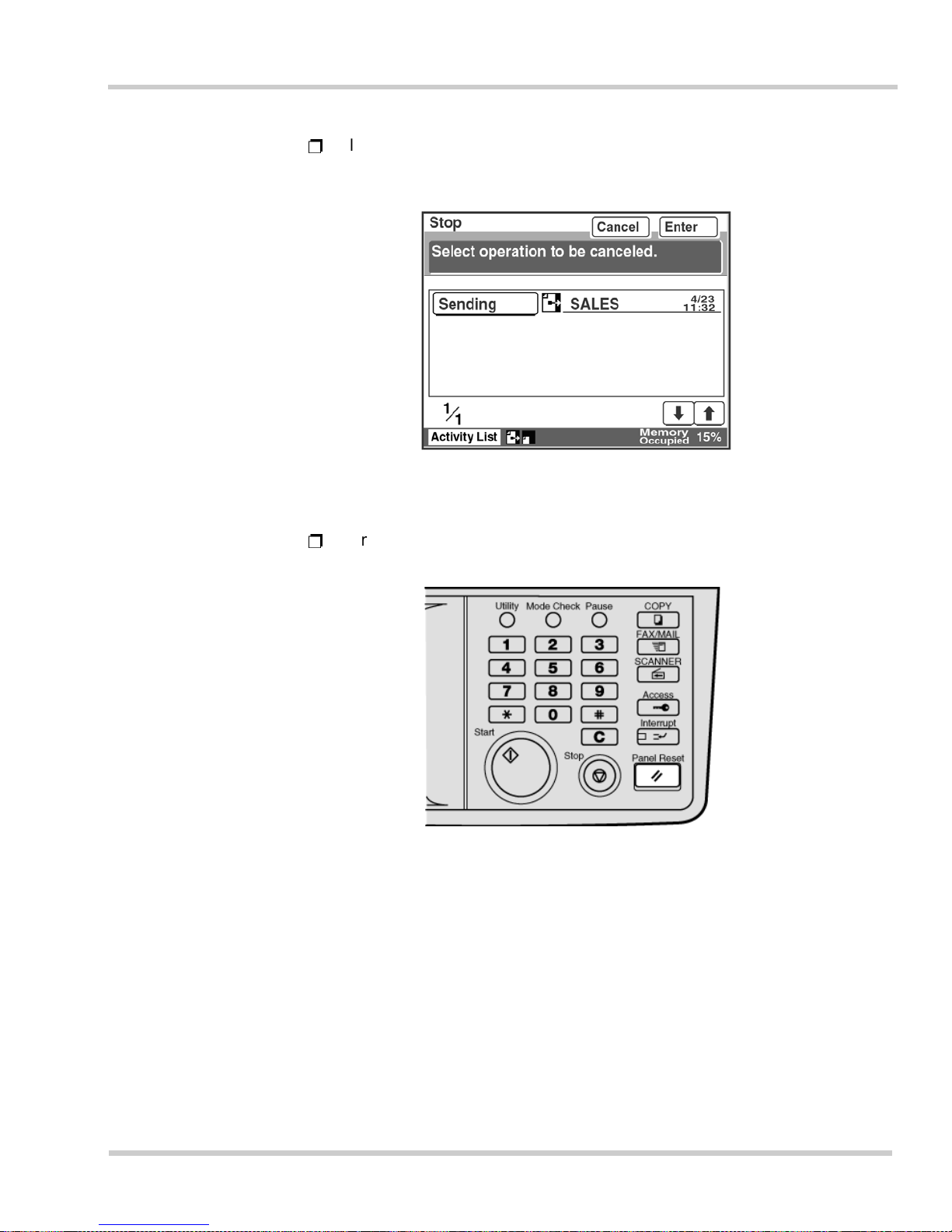
NEC IT Series Issue 1
NEC IT35 10/ I T 2510 Operations Ma nual 1 - 31
Ë
If the <Stop> key is pressed while copying, operation is halted. When
halted, copying may be resumed by pressing the <Start> key.
Ë
Pressing the <Panel Reset> key and all settings for copy and facsimile
functions are cleared.
Figure 1-24 Selecting Which Operation to Cancel
Figure 1-25 Pressing the Panel Reset Key
Page 76
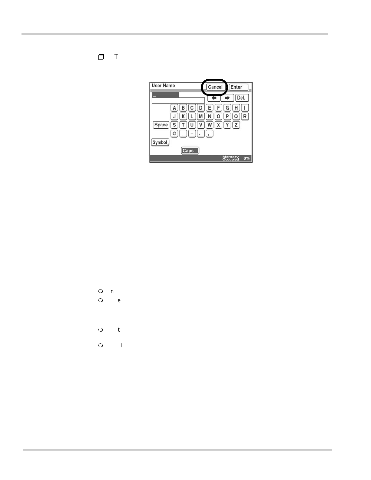
1 - 32 Gett ing Star t ed
Issue 1 NEC IT Series
Ë
The regis tratio n or setti ng scr een c an be canc eled by touch ing [Cancel]
when [Cancel] is displayed on either screen.
SECTION 7INTERRUPTING AN OPERATION
7.1 Interrupting
Copying or pri nting opera tio ns can be susp en ded to all o w other d o c u m ents to
be copied or transmitted.
Before Starting Operations:
Interruption is not possible during document scanning for transmission.
When a facsimile is received while operation is interrupted, the received data is stored
in memory without being printed. For more details, refer to
Section 2.1 Confirming
the Communications Status in Chapter 6 Advanced Sending and Receiving
Operations on page 6-1.
Sorting, grouping, stapling, and hole punching cannot be used when an operation is
interrupted.
The Interrupt key lamp is lit while an operation is being interrupted.
Figure 1-26 Touching Cancel on the Touch Panel
Page 77
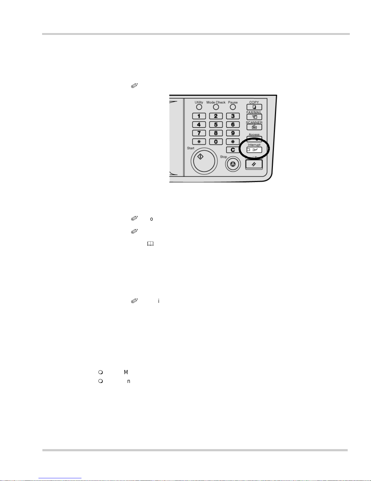
NEC IT Series Issue 1
NEC IT35 10/ I T 2510 Operations Ma nual 1 - 33
How to Interr u p t an Operation
1. Press the <Interrupt> key.
i
To cancel the selection press <Interrupt> once again.
2. Copy or transmit the document.
i
T
o copy a document, press <COPY>.
i
To send a facsi mile, pr ess <FAX>.
For more in fo rmation , refer to Section 1 Basic Copy Operations in Chapter 2
Copy Operations on page 2-1, and Section 2 Basic Sending Operations in
Chapter 5 Basic Sending and Receiving Operations on page 5-1.
3. Press <Interrupt>.
4. The machine will return to the pre-interrupted status.
i
The inte r rupt ed operation can be cont inued.
SECTION 8CONFIRMING THE SETTINGS
Communi c ation s and copie r set ting s can be c onfirmed b y usin g t he Mode Check key.
Before Starting Operations:
The <Mode Check> button on the operation panel will be used to confirm the settings.
Two confirmation categories exist:
Facsimile
Destination confirmation screen: The specified destination can be confirmed and
modified.
Figure 1-27 Pressing the Interrupt Key
Page 78
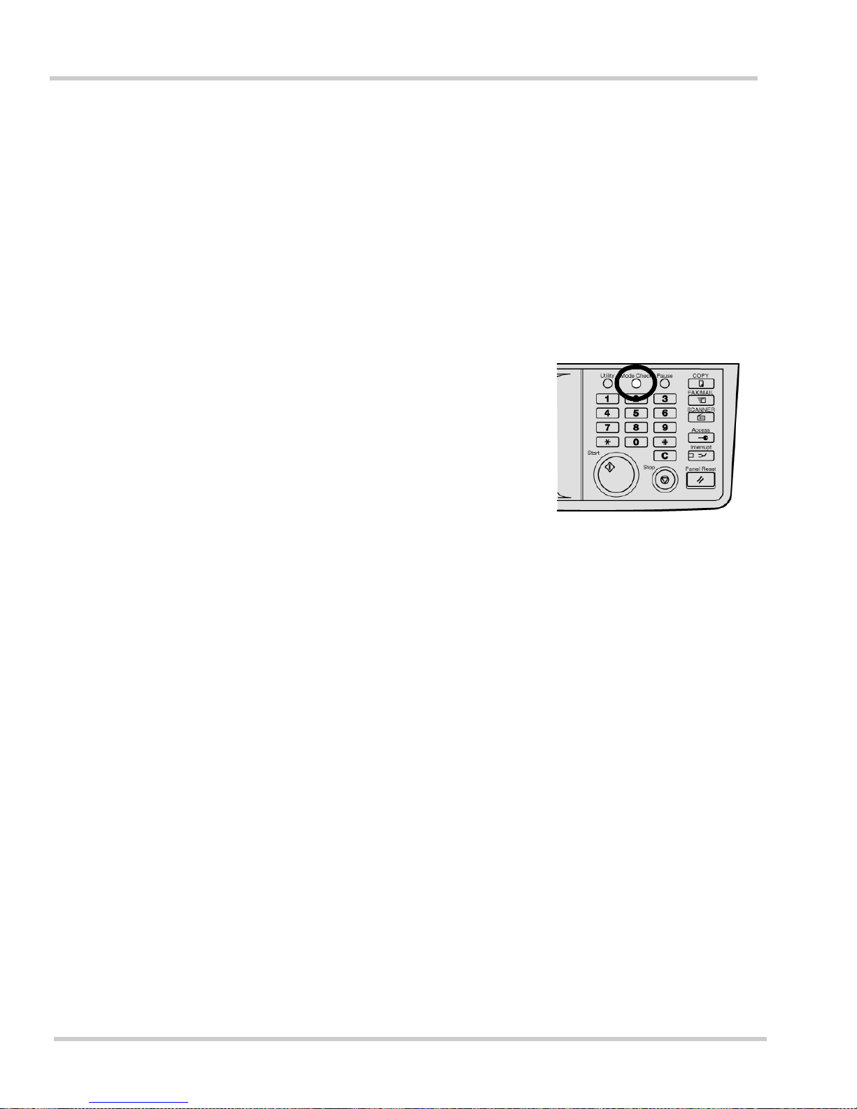
1 - 34 Gett ing Star t ed
Issue 1 NEC IT Series
Quality/Reduction confirmation screen: The settings for image quality, density,
reduction, and scanning area can be confirmed and modified.
FAX Menu confirmation screen: FAX Menu settings can be confirmed and reset.
Copying
Settings confirmation screen: The copy functions that have been set can be
confirmed. The settings can also be reset or cancelled. Functions that have been s et
in advance can be registered into copy program keys.
Confirming Fa csimile Settings
1.
Press <Mode Check> on the
FAX screen.
2.
Confirm th e set t ings.
Page 79
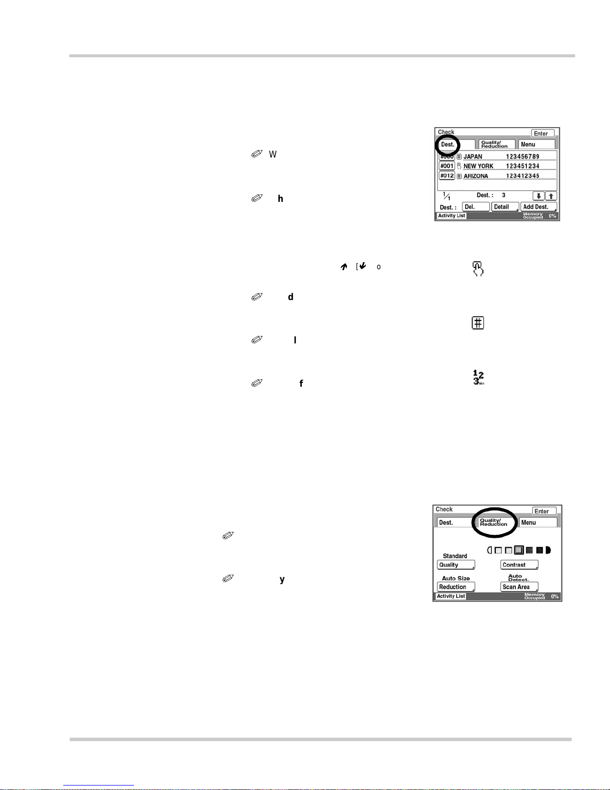
NEC IT Series Issue 1
NEC IT35 10/ I T 2510 Operations Ma nual 1 - 35
1. Touch [Dest.] to confirm the
number.
i
When <Mode Check> is
pressed, this screen is
displayed initially.
i
When multiple
destinations are
selected:
Up to four numbers can be
displa ye d at a time .
If some numbers are not
displayed, touch [] [] to
check them.
i
To add destinations:
Touch [Add Dest.] to select
number.
i
To delete a destination:
Select the key for the number to
be deleted, then touch [Del.].
i
To confirm the
communications mode,
etc.:
Select the key for the number to
be confirmed, and touch
[Detail].
Description of the screen:
This ic on indi cates
a number
selection by a
One-Touch k ey.
This ic on indi cates
a number entered
by Abbreviated
dialing.
This ic on indi cates
a number entered
by the 10-key
Pad.
Confirming the Quality/Reduction Screen Settings
1.
Touch [Quality/Reduction] to
confirm the settings.
i
Confirm settings:
The current settings are displayed
above ea c h key.
i
To modify settings:
Touch the key for the function to be
modifi ed and change th e se tting.
Confirming Fa csimile Settings (Continued)
Page 80
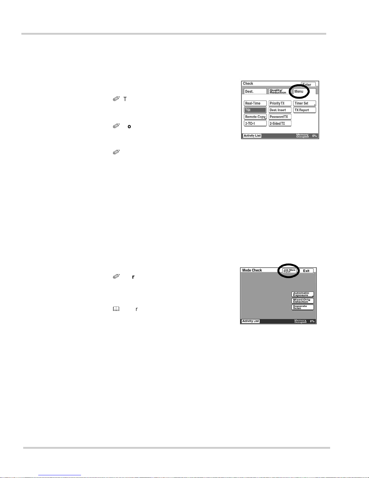
1 - 36 Gett ing Star t ed
Issue 1 NEC IT Series
Confirming th e FAX Menu Settings
1.
Touch [Menu] to confirm the
settings.
i
The TSI is required on all
facsimile transmissions.
It is illegal to turn off this feature!
i
Confirming settings:
The key for a function that has been
selected is displayed in reverse.
i
To cancel settings:
Touch the key for the function to be
canceled. The appearance of the key
returns to normal .
2.
Touch [Enter]. The dis pla y
returns to the FAX screen.
Confirming the Copy Settings
1.
Press <Mode Ch eck> on the
Copy sc reen.
2.
Confirm th e set t ings.
i
To register a copy program:
Touch [Job Mem Input] to regist er the
functi ons that ha ve been sele cted in a
copy program.
Refer to Section 3.4 Registering
Copy Programs in Chapter 4
Advanced Registration and
Setting Operations on page 4-59.
3.
Touch [Exit]. The displa y
returns to the Copy screen.
Page 81
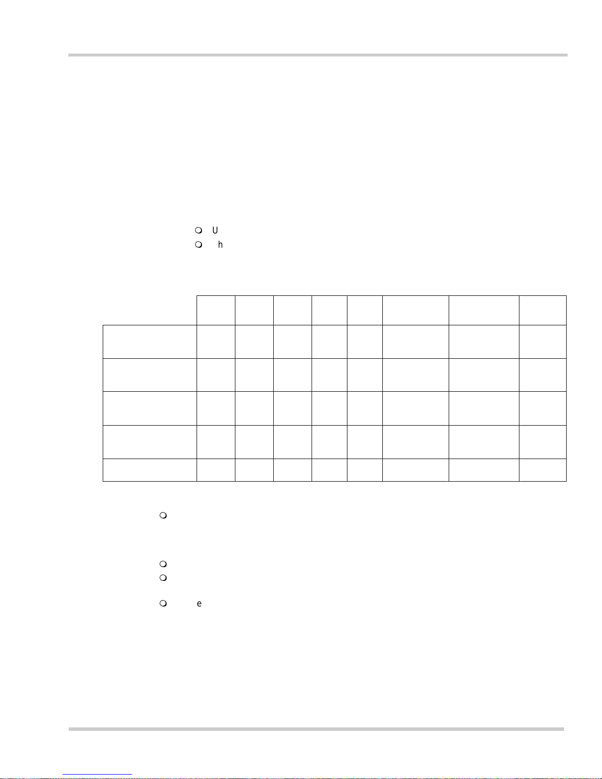
NEC IT Series Issue 1
NEC IT35 10/ I T 2510 Operations Ma nual 1 - 37
SECTION 9ROUTINE CARE
9.1 Installing Print Paper
The fol lowing section describ es th e proc edure f or ins talling print paper in the
paper cassette and changing the paper size.
Before Starting Operations:
Up to five paper cassettes can be installed using additional cassettes (optional items).
The following print sizes can be set:
If there is no paper left for printing, the message "Add paper" is displayed on the touch panel
screen. When the multi-purpose paper cassette, universal paper cassette, or 550-sheet
cassette is installed, and the paper has run out, a red LED on that cassette lights. This LED
will flash when the paper is at low status.
Use only the recommended paper.
When the paper size of the cassette is changed, be sure to change the paper size indicator.
(To change the paper size in a 550-sheet cassette, contact your dealer or service center.)
If the paper size is changed while the power is turned off, reset the paper size on the copy
screen after turning on the power.
o
= Available
x
= Not
Available
11x17 11x14 Legal
Letter
(L)
Letter
(P)
51/2x81/2 (L) 51/2x81/2 (P) OHP
Multi-purpose
cassette
ooooo o o o
Universal
cassette
ooooo x x x
Fixed Universal
cassette
ooooo x x x
Large Capacity
Cabinet
xxxxo x x x
Manual Bypass
ooooo o o o
(L) = Landscape direction (P) = Portrait direction OHP = Overhead Projector (transparencies)
Page 82
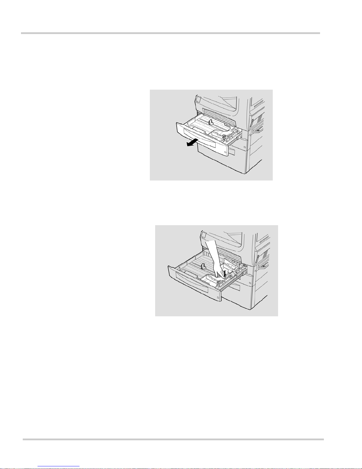
1 - 38 Gett ing Star t ed
Issue 1 NEC IT Series
Loading paper (Mult i-pu r pose casse t te)
1. Pull out the paper cassette.
2. Push down on the paper support until it locks.
Figure 1-28 Pulling Out the Paper Cassette
Figure 1-29 Locking the Paper Support
Page 83
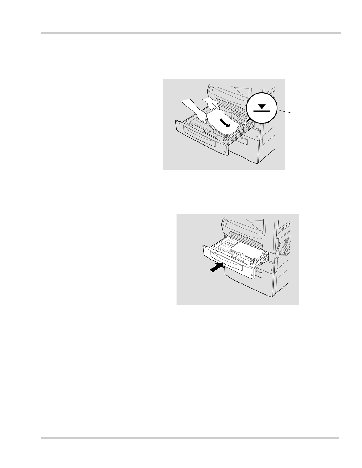
NEC IT Series Issue 1
NEC IT35 10/ I T 2510 Operations Ma nual 1 - 39
3. Insert a qu a ntity of paper into the cassette, being careful not to exceed the
maximum load. This maximum is indicated by a mark on the paper guide.
4. Push the paper cassette back into the machine.
Figure 1-30 Loading the Paper Cassette
Figure 1-31 Pushing In the Paper Cassette
Maximum paper
load indication
Page 84
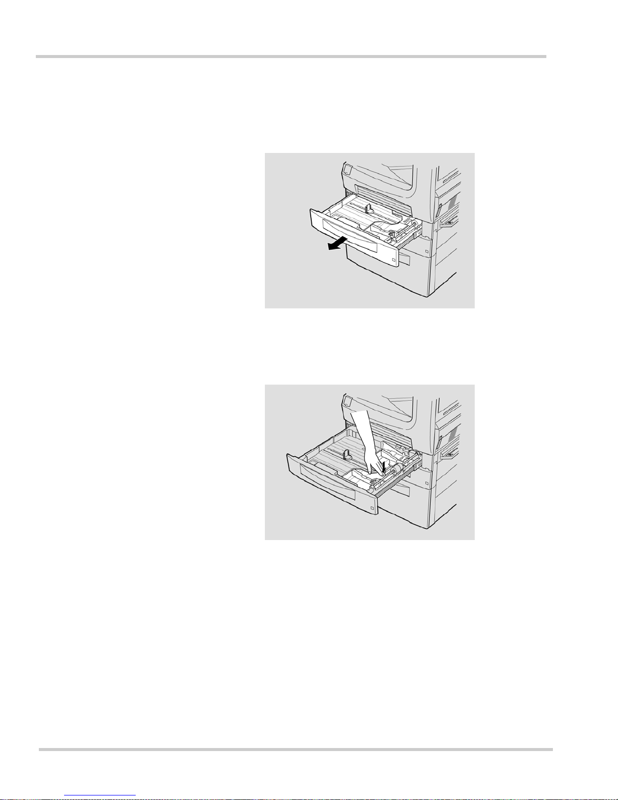
1 - 40 Gett ing Star t ed
Issue 1 NEC IT Series
Changing the Paper Size (Multi-Purpose Cassette)
1. Pull out the paper cassette.
2. Push down on the paper support until it locks.
Figure 1-32 Pulling Out the Paper Cassette
Figure 1-33 Locking the Paper Support
Page 85
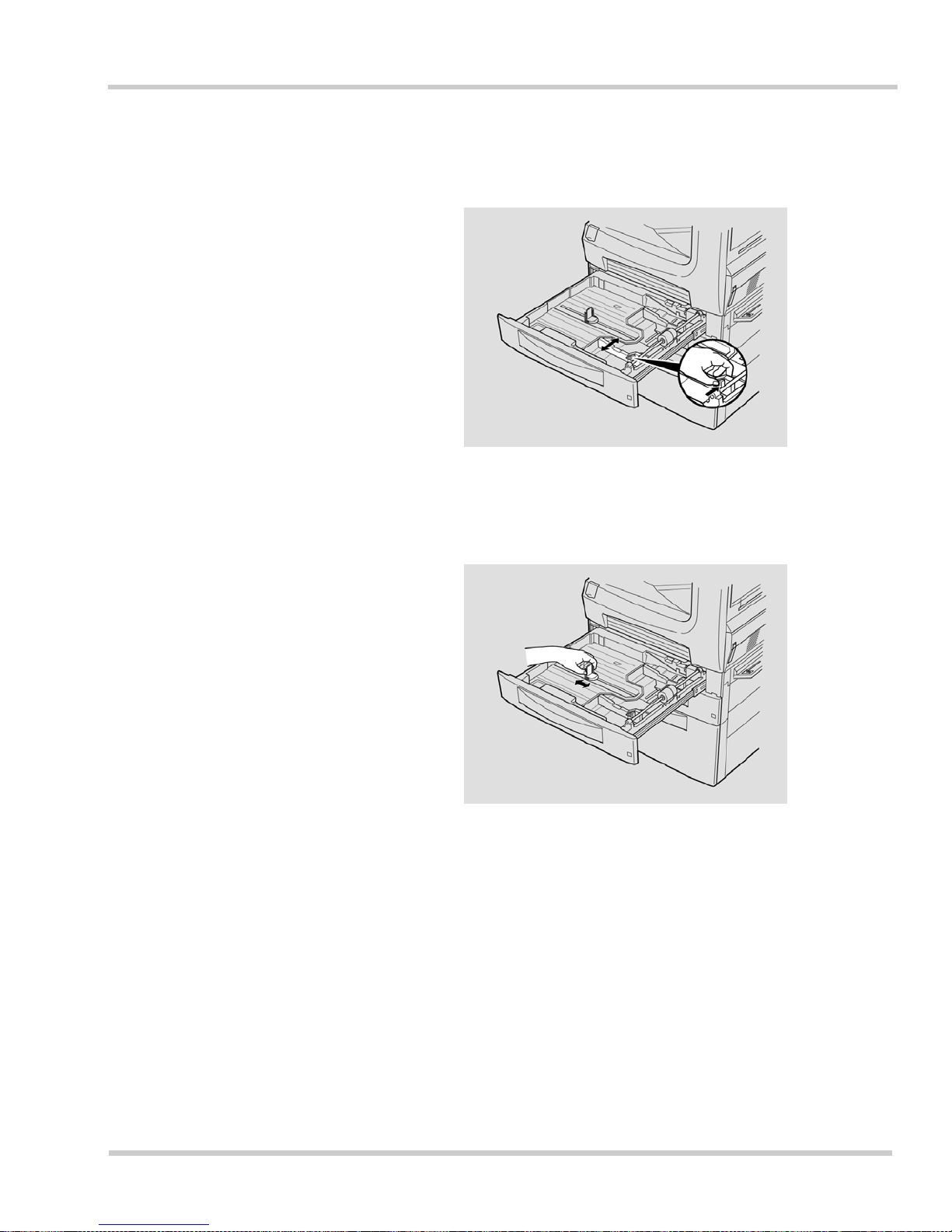
NEC IT Series Issue 1
NEC IT35 10/ I T 2510 Operations Ma nual 1 - 41
3. Pinch the paper width guide with your fingers and slide the paper guide to
the desired width.
4. Hold the paper length guide and slide the guide to the desired length.
Figure 1-34 Adjusting the Paper Width Guide
Figure 1-35 Adjusti ng the Paper Length Guide
Page 86
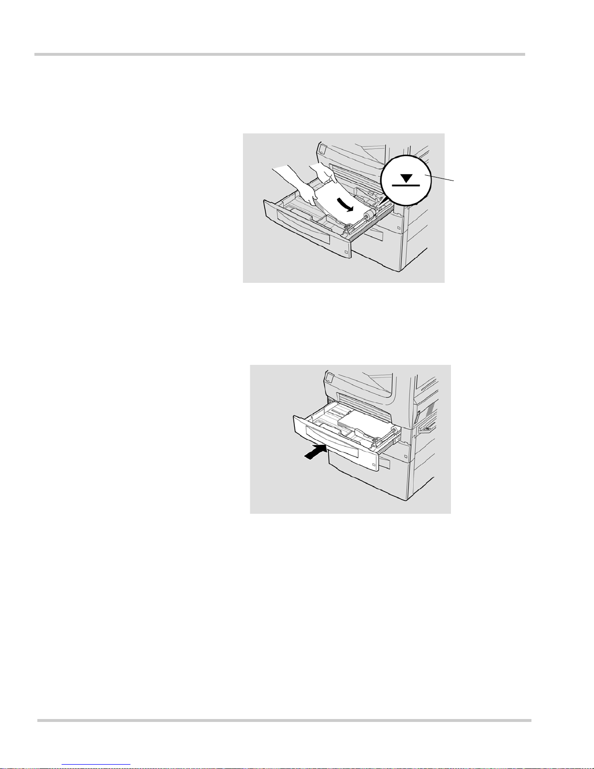
1 - 42 Gett ing Star t ed
Issue 1 NEC IT Series
5. Insert a qu a ntity of paper into the cassette, being careful not to exceed the
maximum load. This maximum is indicated by a mark on the paper guide.
6. Push in the pape r casse tte and r eplace the pap er siz e label t o reflect the
size currently installed.
Figure 1-36 Loading the Paper Cassette
Figure 1-37 Pushing In the Paper Cassette
Maximum paper
load indi ca tio n
Page 87
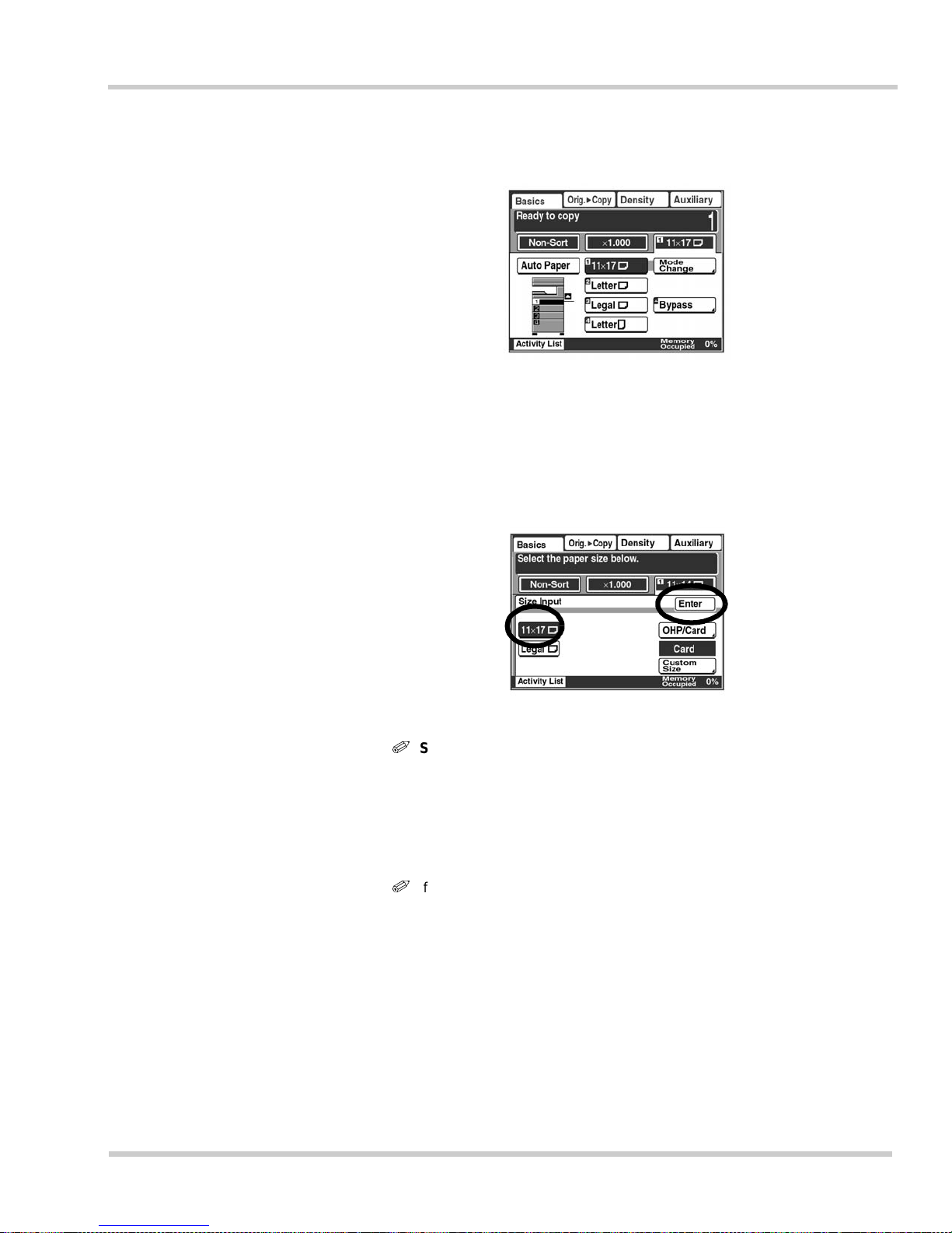
NEC IT Series Issue 1
NEC IT35 10/ I T 2510 Operations Ma nual 1 - 43
7. Set the paper size and with the touch panel.
Setting th e P ap er Size
1. Touch [Change] in the size column.
2. Select the paper size and touch [Enter].
i
Selecting Free Size:
Touch [Custom S iz e ] to u se irregular sized paper.
Touch [X] or [Y] and select the size (in inches) on the free size screen.
X can be set between 5
1/2
and 17 inch es , whi le Y can be set b etw e en 3
9/16
and 11
11/
16
inches.
If the maximum value 17 inches (432 mm) is set for X, Y can only be up to 11 inches
(279 mm).
i
If the maximum value 11
11/16
inches (279 mm) is set for Y, X can only be
up to 16
1/2
inches (420 mm).
Figure 1-38 Changing Paper Size and Type Screen
Figure 1-39 Selecting the Paper Size Screen
Page 88
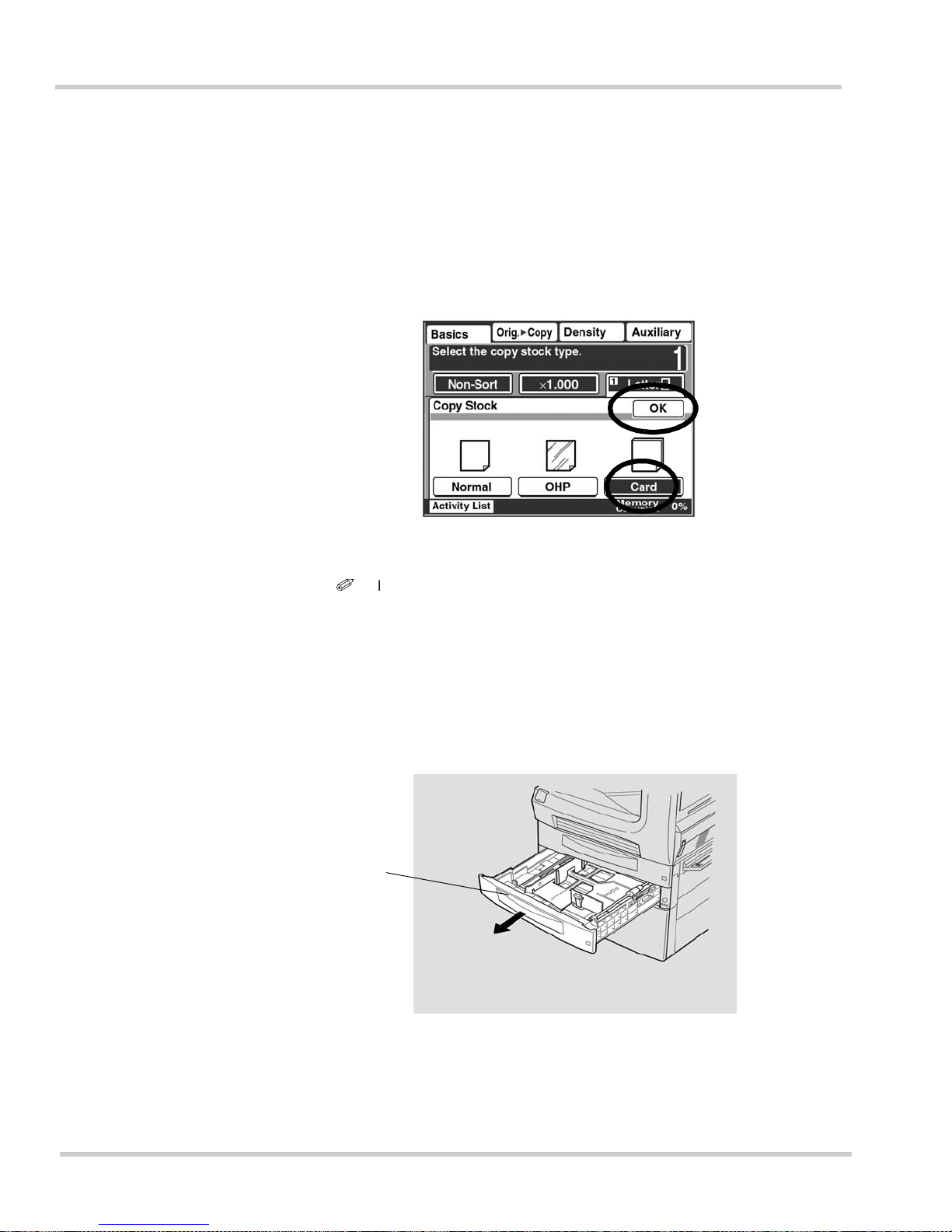
1 - 44 Gett ing Star t ed
Issue 1 NEC IT Series
Setting the Paper Type
1. Touch [Change] in the type column.
2. Select the paper type and touch [Enter].
3. Touch [Enter] repeate dly until the s c reen ret urns t o the stan d-by sc reen.
i
If [OHP] or [Card] is selected, hole-punching, stapling, and 2-Sided
Copying cannot be used.
Loading Paper (Universal Cassette)
1. Pull out the paper cassette.
Figure 1-40 Selecting the Paper Type Screen
Figure 1-41 Pulling Out the Paper Cassette
Universal
Cassette
Page 89
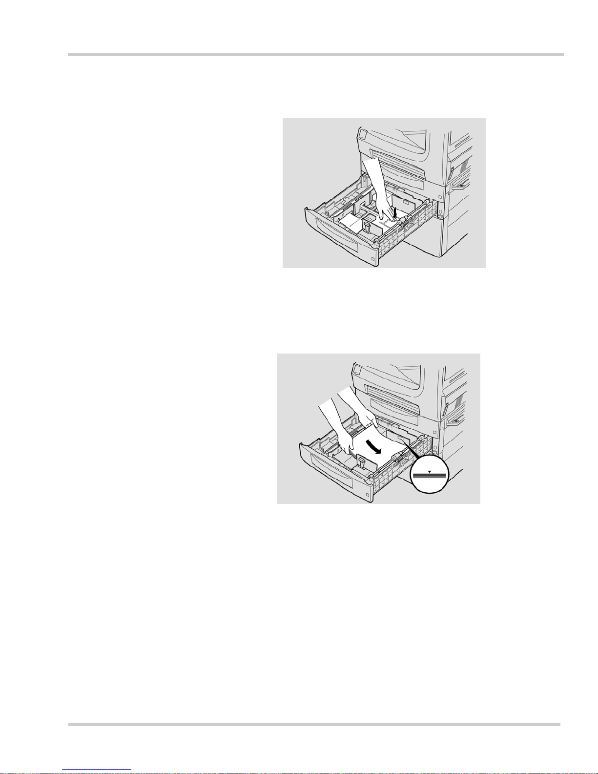
NEC IT Series Issue 1
NEC IT35 10/ I T 2510 Operations Ma nual 1 - 45
2. Push down on the paper support until it locks.
3. Insert a qu a ntity of paper into the cassette, being careful not to exceed the
maximum load. This maximum is indicated by a mark on the paper guide.
Figure 1-42 Locking the Paper Support
Figure 1-43 Loading the Paper Cassette
Page 90
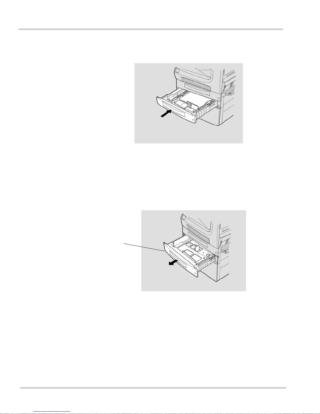
1 - 46 Gett ing Star t ed
Issue 1 NEC IT Series
4. Push the paper cassette back into the machine.
Loading Paper (Fixed Universal Cassette)
1. Pull out the paper cassette.
Figure 1-44 Pushing In the Paper Cassette
Figure 1-45 Pulling Out the P aper Cassette
Fixed
Universal
Cassette
Page 91
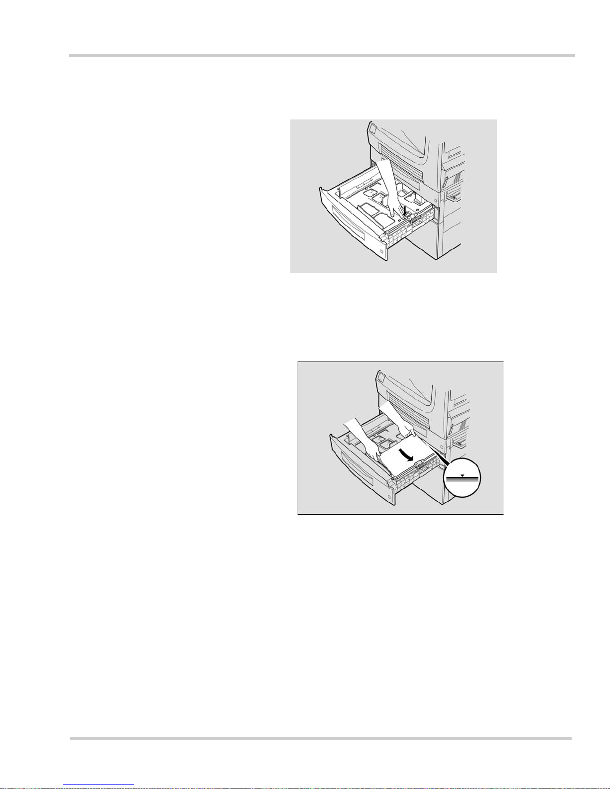
NEC IT Series Issue 1
NEC IT35 10/ I T 2510 Operations Ma nual 1 - 47
2. Push down on the paper support until it locks.
3. Insert a qu a ntity of paper into the cassette, being careful not to exceed the
maximum load. This maximum is indicated by a mark on the paper guide.
Figure 1-46 Locking the Paper Support
Figure 1-47 Loading the Paper Cassette
Page 92
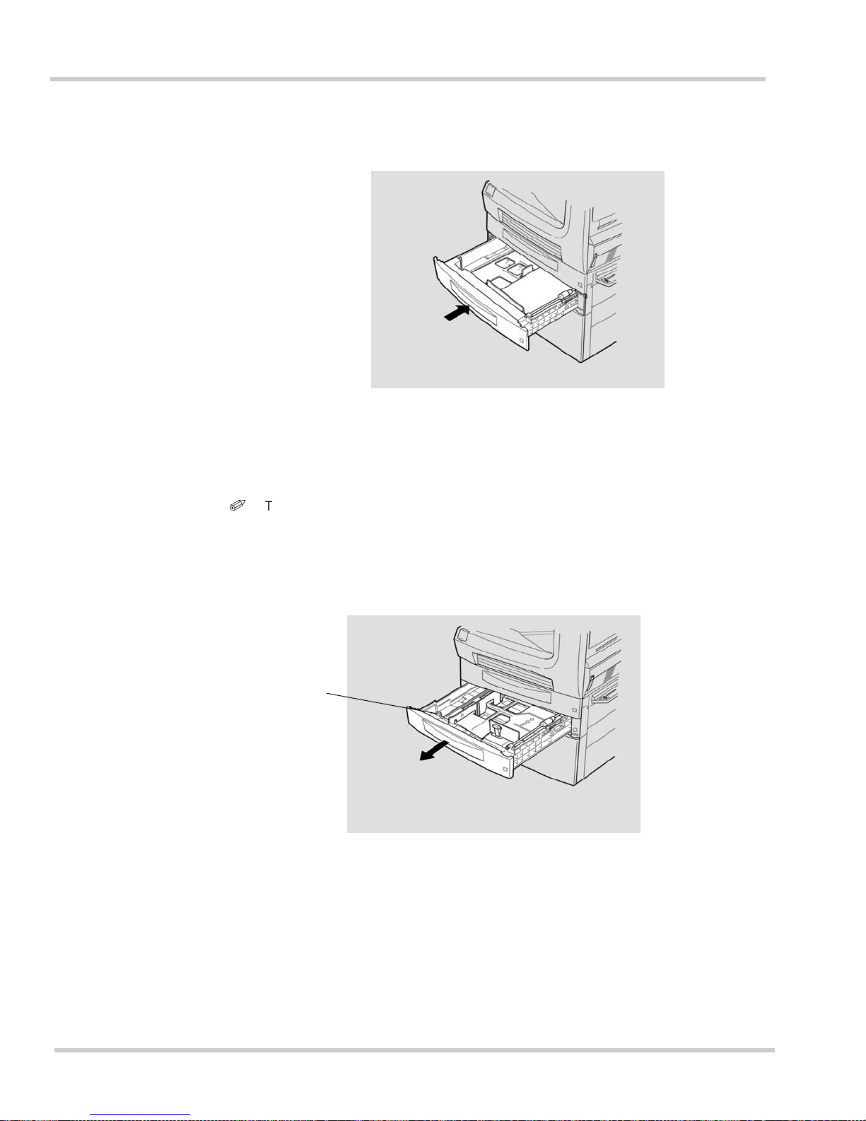
1 - 48 Gett ing Star t ed
Issue 1 NEC IT Series
4. Push the paper cassette back into the machine.
Changing the Paper Size (Universal Cassette only)
i
The print paper size is fixed for the Fixed Universal cassette. To change the size,
contact your dealer or service center.
1. Pull out the paper cassette.
Figure 1-48 Pushing In the Paper Cassette
Figure 1-4 9 Pulling Out the P aper Cassette
Universal
Cassette
Page 93
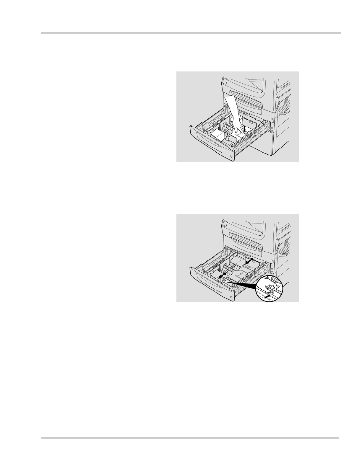
NEC IT Series Issue 1
NEC IT35 10/ I T 2510 Operations Ma nual 1 - 49
2. Push down on the paper support until it locks.
3. Pinch the paper length guide with your fingers and slide the paper guide to
the desired length.
Figure 1-50 Locking the Paper Support
Figure 1-51 Adjusting the Paper Width Guide
Page 94
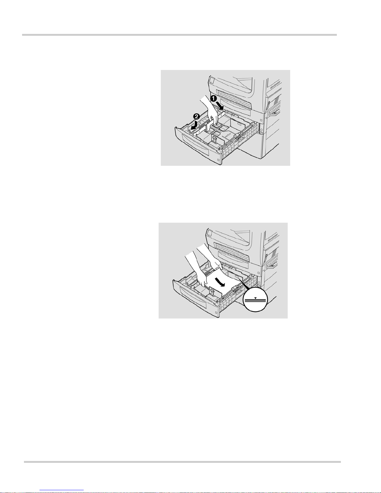
1 - 50 Gett ing Star t ed
Issue 1 NEC IT Series
4. Hold the paper width guide and slide the guide to the desired width.
5. Insert a qu a ntity of paper into the cassette, being careful not to exceed the
maximum load. This maximum is indicated by a mark on the paper guide.
Figure 1-52 Adjusti ng the Paper Length Guide
Figure 1-53 Loading the Paper Cassette
Page 95
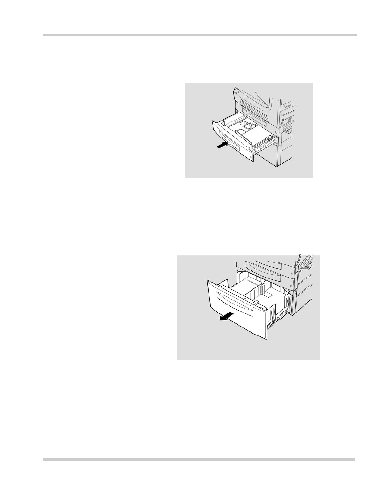
NEC IT Series Issue 1
NEC IT35 10/ I T 2510 Operations Ma nual 1 - 51
6. Push in the pape r casse tte and r eplace the pap er siz e label t o reflect the
size currently installed.
Installing Paper (Large Capacity Cabinet)
1. Pull out the paper cassette.
Figure 1-54 Pushing In the Paper Cassette
Figure 1-55 Pulling Out the Paper Cassette
Page 96
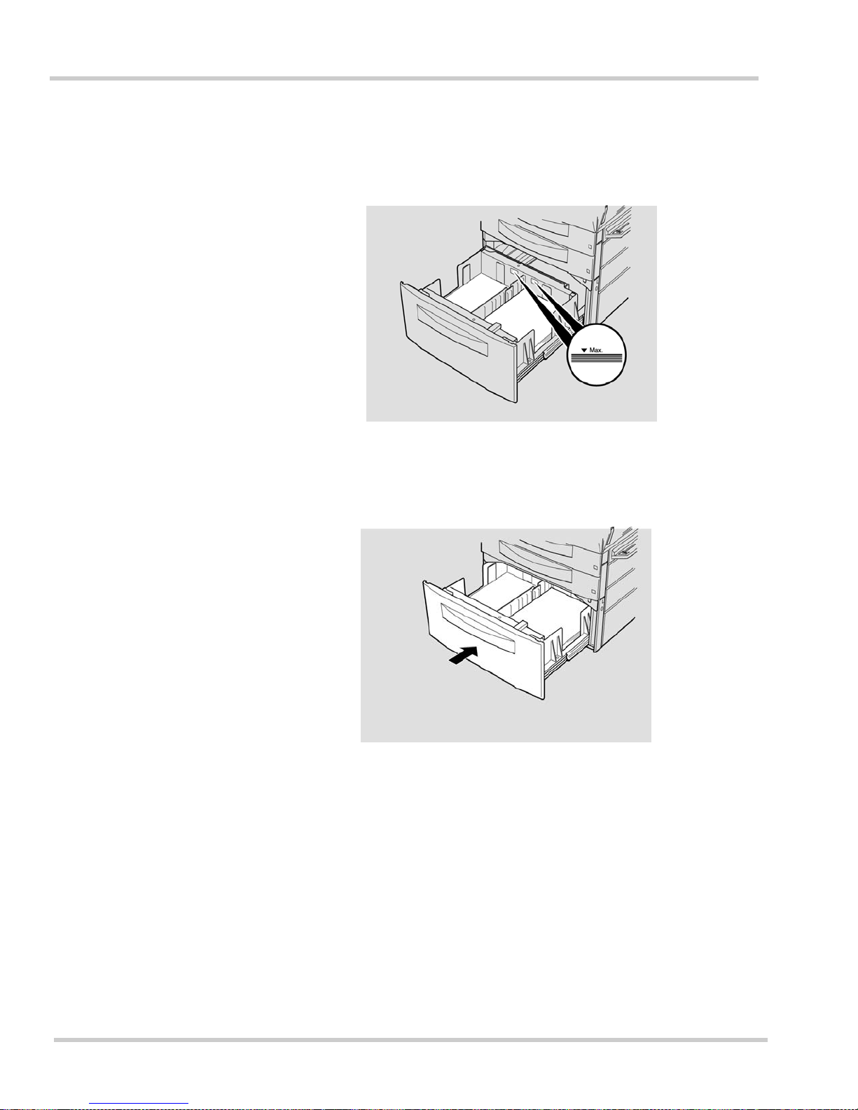
1 - 52 Gett ing Star t ed
Issue 1 NEC IT Series
2. Insert a quantity of paper into the cassette, being careful not to e xceed
the maximum load. This maximum is indicated by a mark on the paper
guide. Paper can be installed in both sides of the cassette.
3. Push the paper cassette back into the machine.
Figure 1-56 Loading the Paper Cassette
Figure 1-57 Pushing In the Paper Cassette
Page 97
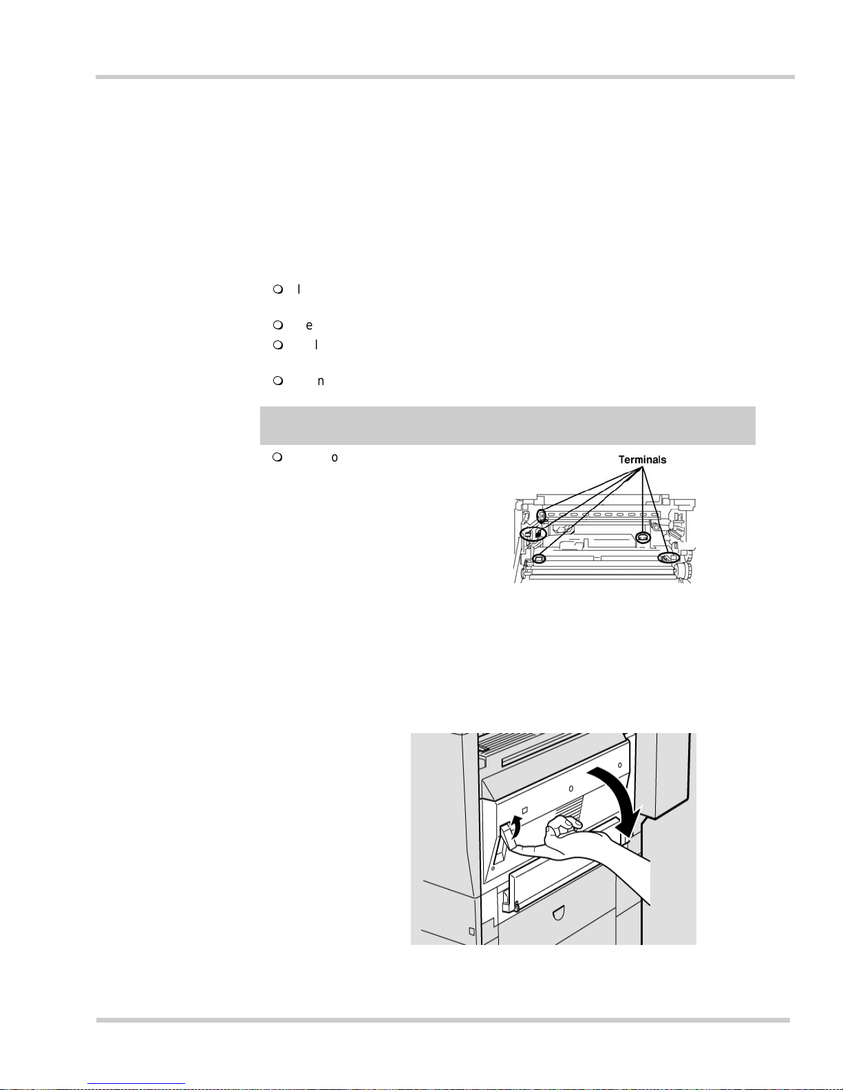
NEC IT Series Issue 1
NEC IT35 10/ I T 2510 Operations Ma nual 1 - 53
9.2 Installing and Replacing the Imaging Unit and Toner Bottle
This section illustrates how to install the Imaging Unit (IU). If the machine
already has an Imaging Unit installed and the message "The Imaging Unit
needs to be c han ge d" app ea rs on the to uch pa nel s cree n, it will be neces sa ry
to replace the Imaging Unit.
Before Starting Operations:
If an Imaging Unit is already being used in the machine, do not pull out the IU unless
the alarm message is displayed on the touch panel screen.
Keep the IU in a flat, horizontal position at all times.
Only use an NEC America, Inc. authorized Imaging Unit. Use of unauthorized
consumable parts may cause product failure or poor print quality.
Do not drop or mishandle the IU.
Installing and Replacing the Imaging Unit (IU)
1. Pull the lever and open the side cover.
Caution
Do not touch the copper
terminals inside the side
cover and the bottom of the
Imaging Unit, as static
electricity discharge may
cause failure.
Figure 1-58 Opening the Side Cover
Page 98
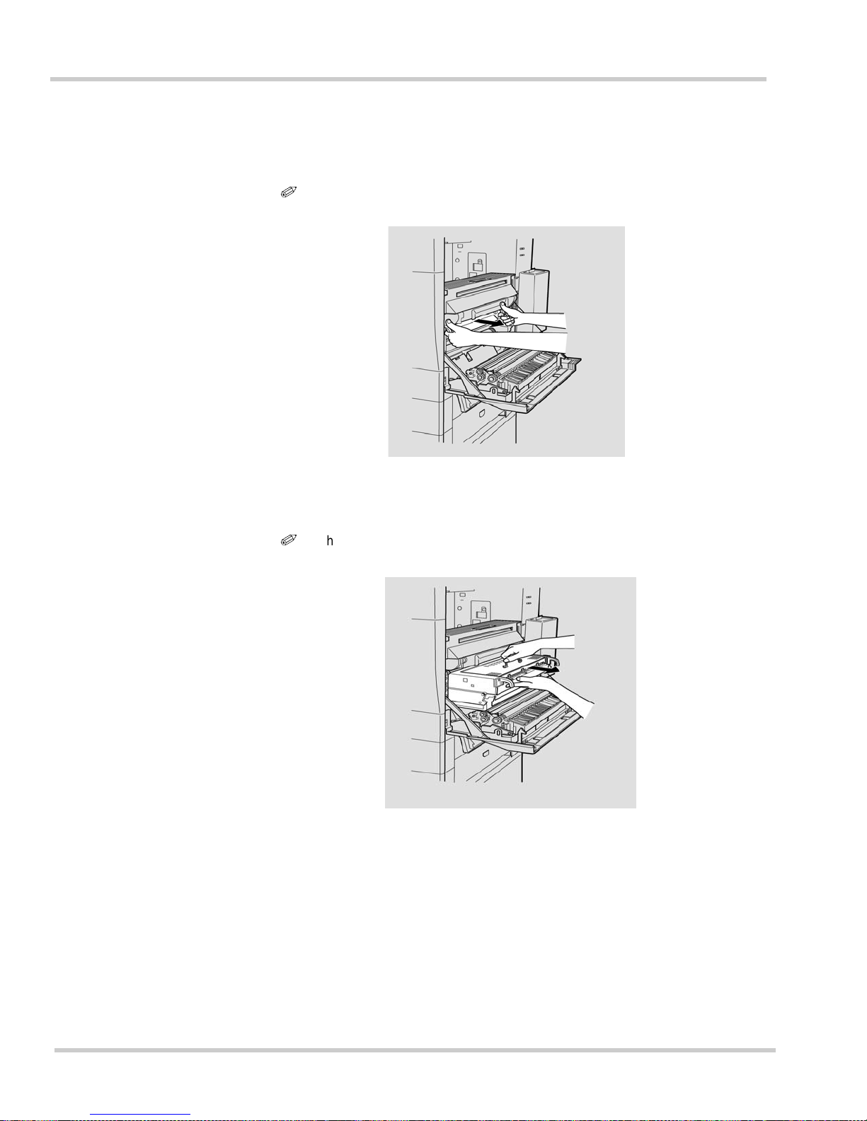
1 - 54 Gett ing Star t ed
Issue 1 NEC IT Series
2. If an old IU is to be replaced, pull out the used IU by grasping the green
levers while pushing firmly against the machine’s body with your
thumbs.
i
This step is not necessary when installing the initial IU.
3. While holding the handle with one hand, gently pull out the used IU.
i
This step is not necessary when installing the initial IU.
Figure 1-59 Opening the Side Cover
Figure 1-60 Pulling Out the Used Imaging Unit
Page 99
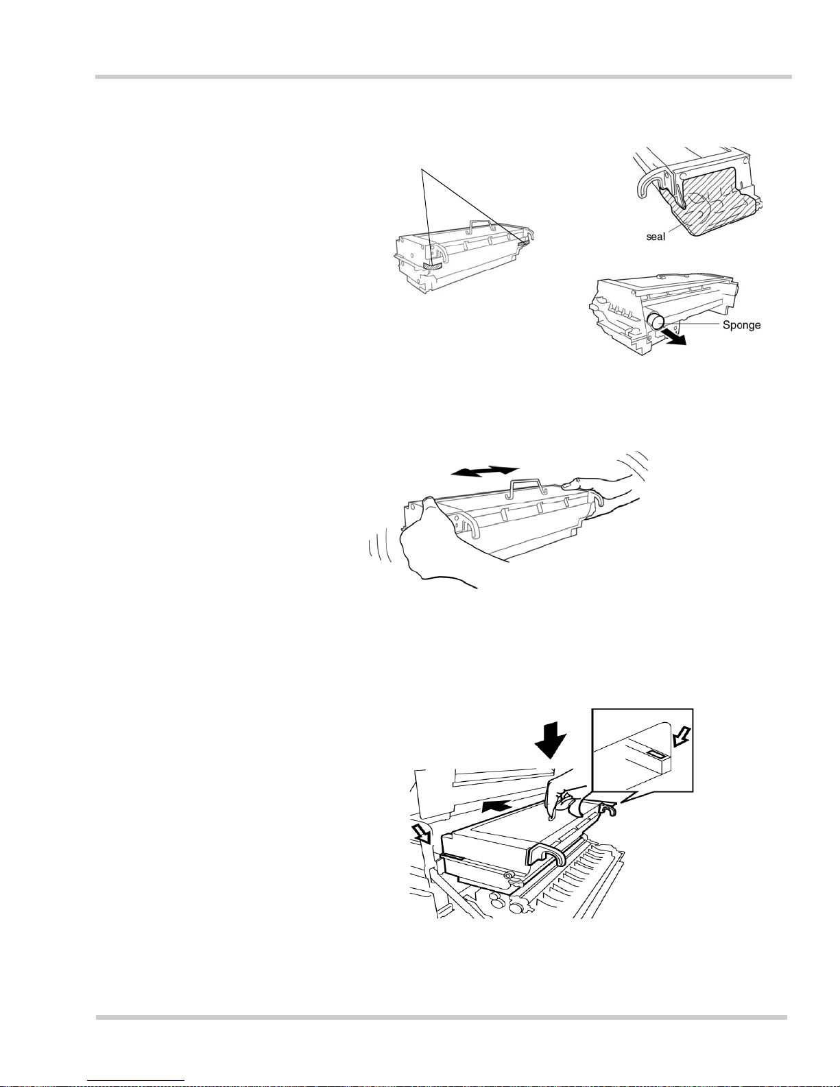
NEC IT Series Issue 1
NEC IT35 10/ I T 2510 Operations Ma nual 1 - 55
4. Remove the seal, tape, and sponge from the new IU.
5. Shake the new IU horizontally about four t o fi ve ti me s .
6. Set the new IU on the rails inside the ma chine. Push in the IU all the
way until it locks into place.
Figure 1-61 Removing the Packing Items from Imaging Unit
Figure 1-62 Shaking the New Imaging Unit
Figure 1-63 Inserting the New Imaging Unit
Tape
Page 100
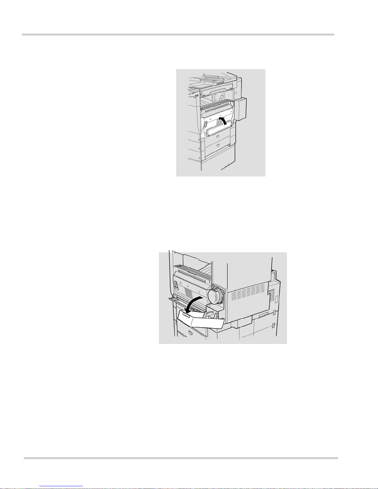
1 - 56 Gett ing Star t ed
Issue 1 NEC IT Series
7. Close the side co ver.
9.3 Installing and Replacing the Toner Bottle
1. Pull down on the toner bottle housing area cover.
Figure 1-64 Closing the Side Cover
Figure 1-65 Opening the T oner Bottle Cover
 Loading...