

Page 1
STOCK # 151988
®
ISDN System Manual
ND-70919 (E)
ISSUE 1
FEBRUARY, 2000
NEC America, Inc.
Page 2

LIABILITY DISCLAIMER
NEC America, Inc. reserves the right to change the specifications,
functions, or features, at any time, without notice.
NEC America, Inc. has prepared this document for use by its
employees and custome rs. The information contained herein is
the property of NEC America, Inc. and shall not be reproduced
without prior written approval from NEC America, Inc.
NEAX and D
term
are registered trademar ks of NEC Corporation.
MATWorX is a trademark of NEC C orpor ati on.
Copyright 2000
NEC America, Inc.
Printed in U.S.A.
Page 3

PAGE No.
i 1
ii 1
iii 1
iv
v 1
vi 1
1 1
2
3 1
4 1
5 1
6
7 1
8 1
9 1
10
11 1
12 1
13 1
14
15 1
16 1
17 1
18
19 1
20 1
21 1
22
23 1
24 1
25 1
26
27 1
28 1
29 1
30
31 1
32 1
DATE FEBRU ARY, 2000 DATE DATE DATE
DA TE DATE DA TE DATE
NEAX2000 IVS
12345678
1
1
1
1
1
1
1
1
1
ISSUE 1 ISSUE 2 ISSUE 3 ISSUE 4
ISSUE 5 ISSUE 6 ISSUE 7 ISSUE 8
2
ISSUE No.
PAGE No.
33 1
34
35 1
36 1
37 1
38
39 1
40 1
41 1
42
43 1
44 1
45 1
46
47 1
48 1
49 1
50
51 1
52 1
53 1
54
55 1
56 1
57 1
58
59 1
60 1
61 1
62
63 1
64 1
65 1
66
67 1
68 1
69 1
70
12345678
1
1
1
1
1
1
1
1
1
1
ISDN System Manual
ISSUE No.
Revision Sheet 1/3
ND-70919 (E)
Page 4

PAGE No.
71 1
72 1
73 1
74
75 1
76 1
77 1
78
79 1
80 1
81 1
82
83 1
84 1
85 1
86
87 1
88 1
89 1
90
91 1
92 1
93 1
94
95 1
96 1
97 1
98
99 1
100 1
101 1
102
103 1
104 1
105 1
106
107 1
108 1
DATE FEBRU ARY, 2000 DATE DATE DATE
DA TE DATE DA TE DATE
NEAX2000 IVS
12345678
1
1
1
1
1
1
1
1
1
ISSUE 1 ISSUE 2 ISSUE 3 ISSUE 4
ISSUE 5 ISSUE 6 ISSUE 7 ISSUE 8
2
ISSUE No.
PAGE No.
109 1
110
111 1
112 1
113 1
114
115 1
116 1
117 1
118
119 1
120 1
121 1
122
123 1
124 1
125 1
126
127 1
128 1
129 1
130
131 1
132 1
133 1
134
135 1
136 1
137 1
138
139 1
140 1
141 1
142
143 1
144 1
145 1
146
12345678
1
1
1
1
1
1
1
1
1
1
ISDN System Manual
ISSUE No.
Revision Sheet 2/3
ND-70919 (E)
Page 5

PAGE No.
147 1
148 1
149 1
150
151 1
152 1
153 1
154
155 1
156 1
157 1
158
159 1
160 1
161 1
162
163 1
164 1
165 1
166
167 1
168 1
169 1
170
171 1
172 1
173 1
174
175 1
176 1
177 1
178
179 1
180 1
181 1
182
183 1
184 1
DATE FEBRU ARY, 2000 DATE DATE DATE
DA TE DATE DA TE DATE
NEAX2000 IVS
12345678
1
1
1
1
1
1
1
1
1
ISSUE 1 ISSUE 2 ISSUE 3 ISSUE 4
ISSUE 5 ISSUE 6 ISSUE 7 ISSUE 8
2
ISSUE No.
PAGE No.
185 1
186
187 1
188 1
189 1
190
191 1
192 1
193 1
194
195 1
196 1
197 1
198
199 1
200 1
12345678
1
1
1
1
ISDN System Manual
ISSUE No.
Revision Sheet 3/3
ND-70919 (E)
Page 6

NEAX2000 IVS
2
ISDN System Manual
TABLE OF CONTENTS
Page
LIST OF FIGURES . . . . . . . . . . . . . . . . . . . . . . . . . . . . . . . . . . . . . . . . . . . . . . . . . . . . . . . . iv
LIST OF TABLES . . . . . . . . . . . . . . . . . . . . . . . . . . . . . . . . . . . . . . . . . . . . . . . . . . . . . . . . . v
INTRODUCTION . . . . . . . . . . . . . . . . . . . . . . . . . . . . . . . . . . . . . . . . . . . . . . . . . . . . . . . . . 1
PURPOSE . . . . . . . . . . . . . . . . . . . . . . . . . . . . . . . . . . . . . . . . . . . . . . . . . . . . . . . . . . . . . . . . . . 1
OUTLINE OF THIS MANUAL. . . . . . . . . . . . . . . . . . . . . . . . . . . . . . . . . . . . . . . . . . . . . . . . . . . . 1
REFERENCE MANUALS. . . . . . . . . . . . . . . . . . . . . . . . . . . . . . . . . . . . . . . . . . . . . . . . . . . . . . . 2
CHAPTER 1 GENERAL INFORMATION . . . . . . . . . . . . . . . . . . . . . . . . . . . . . . . . . . . . . 3
SYSTEM OUTLINE . . . . . . . . . . . . . . . . . . . . . . . . . . . . . . . . . . . . . . . . . . . . . . . . . . . . . . . . . . . 4
System Outline of ISDN-PRI . . . . . . . . . . . . . . . . . . . . . . . . . . . . . . . . . . . . . . . . . . . . . . . . . 4
System Outline of ISDN-BRI . . . . . . . . . . . . . . . . . . . . . . . . . . . . . . . . . . . . . . . . . . . . . . . . . 5
System Outline of ISDN-VPN . . . . . . . . . . . . . . . . . . . . . . . . . . . . . . . . . . . . . . . . . . . . . . . . 6
System Outline of ISDN Terminal . . . . . . . . . . . . . . . . . . . . . . . . . . . . . . . . . . . . . . . . . . . . . 8
DTI . . . . . . . . . . . . . . . . . . . . . . . . . . . . . . . . . . . . . . . . . . . . . . . . . . . . . . . . . . . . . . . . . . . . . 10
DCH . . . . . . . . . . . . . . . . . . . . . . . . . . . . . . . . . . . . . . . . . . . . . . . . . . . . . . . . . . . . . . . . . . . . 10
PRT . . . . . . . . . . . . . . . . . . . . . . . . . . . . . . . . . . . . . . . . . . . . . . . . . . . . . . . . . . . . . . . . . . . . 10
BRT . . . . . . . . . . . . . . . . . . . . . . . . . . . . . . . . . . . . . . . . . . . . . . . . . . . . . . . . . . . . . . . . . . . . 11
PLO . . . . . . . . . . . . . . . . . . . . . . . . . . . . . . . . . . . . . . . . . . . . . . . . . . . . . . . . . . . . . . . . . . . . 12
ICH . . . . . . . . . . . . . . . . . . . . . . . . . . . . . . . . . . . . . . . . . . . . . . . . . . . . . . . . . . . . . . . . . . . . . 13
ILC . . . . . . . . . . . . . . . . . . . . . . . . . . . . . . . . . . . . . . . . . . . . . . . . . . . . . . . . . . . . . . . . . . . . . 13
OUTLINE OF EVENT BASED CCIS . . . . . . . . . . . . . . . . . . . . . . . . . . . . . . . . . . . . . . . . . . . . . . 14
Common Channel and Voice Channel Link Control . . . . . . . . . . . . . . . . . . . . . . . . . . . . . . . 15
Event Based CCIS Feature List . . . . . . . . . . . . . . . . . . . . . . . . . . . . . . . . . . . . . . . . . . . . . . . 17
Event Based CCIS Service Conditions . . . . . . . . . . . . . . . . . . . . . . . . . . . . . . . . . . . . . . . . . 20
CARD NAME AND FUNCTION . . . . . . . . . . . . . . . . . . . . . . . . . . . . . . . . . . . . . . . . . . . . . . . . . . 21
SYSTEM CAPACITY . . . . . . . . . . . . . . . . . . . . . . . . . . . . . . . . . . . . . . . . . . . . . . . . . . . . . . . . . . 22
System Capacity for ISDN-PRI . . . . . . . . . . . . . . . . . . . . . . . . . . . . . . . . . . . . . . . . . . . . . . . 22
System Capacity for ISDN-BRI . . . . . . . . . . . . . . . . . . . . . . . . . . . . . . . . . . . . . . . . . . . . . . . 23
SYSTEM CONDITIONS . . . . . . . . . . . . . . . . . . . . . . . . . . . . . . . . . . . . . . . . . . . . . . . . . . . . . . . . 24
Time Slot Assignment Condition . . . . . . . . . . . . . . . . . . . . . . . . . . . . . . . . . . . . . . . . . . . . . . 24
Time Slot Allocation for DTI/PRT/DCH Card . . . . . . . . . . . . . . . . . . . . . . . . . . . . . . . . . . . . . 25
Line Distance Between PBX and NT1/ISDN Terminal . . . . . . . . . . . . . . . . . . . . . . . . . . . . . 26
DTI SPECIFICATIONS. . . . . . . . . . . . . . . . . . . . . . . . . . . . . . . . . . . . . . . . . . . . . . . . . . . . . . . . . 27
Transmission Characteristics . . . . . . . . . . . . . . . . . . . . . . . . . . . . . . . . . . . . . . . . . . . . . . . . . 27
Frame Configuration of 24DTI . . . . . . . . . . . . . . . . . . . . . . . . . . . . . . . . . . . . . . . . . . . . . . . . 29
Frame Configuration of 30DTI . . . . . . . . . . . . . . . . . . . . . . . . . . . . . . . . . . . . . . . . . . . . . . . . 33
CHAPTER 2 INSTALLATION . . . . . . . . . . . . . . . . . . . . . . . . . . . . . . . . . . . . . . . . . . . . . . 35
PRECAUTIONS . . . . . . . . . . . . . . . . . . . . . . . . . . . . . . . . . . . . . . . . . . . . . . . . . . . . . . . . . . . . . . 36
Static Electricity Guard . . . . . . . . . . . . . . . . . . . . . . . . . . . . . . . . . . . . . . . . . . . . . . . . . . . . . 36
NEAX2000 IVS2 ISDN System Manual
ND-70919 (E), Issue 1.0
Page i
Page 7

TABLE OF CONTENTS
Page
REQUIRED EQUIPMENT . . . . . . . . . . . . . . . . . . . . . . . . . . . . . . . . . . . . . . . . . . . . . . . . . . . . . . 39
ISDN-PRI Required Equipment . . . . . . . . . . . . . . . . . . . . . . . . . . . . . . . . . . . . . . . . . . . . . . . 39
ISDN-BRI Required Equipment . . . . . . . . . . . . . . . . . . . . . . . . . . . . . . . . . . . . . . . . . . . . . . . 39
ISDN Terminal Required Equipment . . . . . . . . . . . . . . . . . . . . . . . . . . . . . . . . . . . . . . . . . . . 40
Event Based CCIS Required Equipment . . . . . . . . . . . . . . . . . . . . . . . . . . . . . . . . . . . . . . . . 40
INSTALLATION PROCEDURE FOR ISDN-PRI. . . . . . . . . . . . . . . . . . . . . . . . . . . . . . . . . . . . . . 41
Mounting DTI and DCH Card/PRT Card . . . . . . . . . . . . . . . . . . . . . . . . . . . . . . . . . . . . . . . . 42
Mounting CONN Card . . . . . . . . . . . . . . . . . . . . . . . . . . . . . . . . . . . . . . . . . . . . . . . . . . . . . . 43
DTI/PRT Cable Connection via MDF . . . . . . . . . . . . . . . . . . . . . . . . . . . . . . . . . . . . . . . . . . . 44
Cable Connection via CONN Card . . . . . . . . . . . . . . . . . . . . . . . . . . . . . . . . . . . . . . . . . . . . 47
INSTALLATION PROCEDURE FOR ISDN-BRI. . . . . . . . . . . . . . . . . . . . . . . . . . . . . . . . . . . . . . 49
Mounting BRT Card . . . . . . . . . . . . . . . . . . . . . . . . . . . . . . . . . . . . . . . . . . . . . . . . . . . . . . . . 50
BRT Cable Connection via MDF . . . . . . . . . . . . . . . . . . . . . . . . . . . . . . . . . . . . . . . . . . . . . . 51
INSTALLATION PROCEDURE FOR ISDN TERMINAL. . . . . . . . . . . . . . . . . . . . . . . . . . . . . . . . 55
Mounting ICH Card . . . . . . . . . . . . . . . . . . . . . . . . . . . . . . . . . . . . . . . . . . . . . . . . . . . . . . . . 56
Mounting ILC Card . . . . . . . . . . . . . . . . . . . . . . . . . . . . . . . . . . . . . . . . . . . . . . . . . . . . . . . . . 57
ILC Cable Connection via MDF . . . . . . . . . . . . . . . . . . . . . . . . . . . . . . . . . . . . . . . . . . . . . . . 58
INSTALLATION PROCEDURE FOR EVENT BASED CCIS . . . . . . . . . . . . . . . . . . . . . . . . . . . . 61
Mounting CCH Card . . . . . . . . . . . . . . . . . . . . . . . . . . . . . . . . . . . . . . . . . . . . . . . . . . . . . . . 62
CHAPTER 3 SYSTEM DATA PROGRAMMING . . . . . . . . . . . . . . . . . . . . . . . . . . . . . . . . 63
HOW TO READ THIS CHAPTER. . . . . . . . . . . . . . . . . . . . . . . . . . . . . . . . . . . . . . . . . . . . . . . . . 64
ISDN-PRI PROGRAMMING. . . . . . . . . . . . . . . . . . . . . . . . . . . . . . . . . . . . . . . . . . . . . . . . . . . . . 65
Digital Trunk Data Assignment . . . . . . . . . . . . . . . . . . . . . . . . . . . . . . . . . . . . . . . . . . . . . . . 65
D Channel Handler Assignment . . . . . . . . . . . . . . . . . . . . . . . . . . . . . . . . . . . . . . . . . . . . . . 73
ISDN-BRI PROGRAMMING. . . . . . . . . . . . . . . . . . . . . . . . . . . . . . . . . . . . . . . . . . . . . . . . . . . . . 75
BRT Assignment . . . . . . . . . . . . . . . . . . . . . . . . . . . . . . . . . . . . . . . . . . . . . . . . . . . . . . . . . . 75
ISDN FEATURE PROGRAMMING . . . . . . . . . . . . . . . . . . . . . . . . . . . . . . . . . . . . . . . . . . . . . . . 82
DID Addressing . . . . . . . . . . . . . . . . . . . . . . . . . . . . . . . . . . . . . . . . . . . . . . . . . . . . . . . . . . . 83
MEGACOM
SID to Network-Present/CPN to Network-Present . . . . . . . . . . . . . . . . . . . . . . . . . . . . . . . . . 86
Subaddress-Present . . . . . . . . . . . . . . . . . . . . . . . . . . . . . . . . . . . . . . . . . . . . . . . . . . . . . . . 89
Trunk Provisioning Service Selection . . . . . . . . . . . . . . . . . . . . . . . . . . . . . . . . . . . . . . . . . . 90
ISDN PRI Call By Call Service Selection . . . . . . . . . . . . . . . . . . . . . . . . . . . . . . . . . . . . . . . . 91
Advice of Charge (AOC) . . . . . . . . . . . . . . . . . . . . . . . . . . . . . . . . . . . . . . . . . . . . . . . . . . . . 97
Centrex SHF Over ISDN . . . . . . . . . . . . . . . . . . . . . . . . . . . . . . . . . . . . . . . . . . . . . . . . . . . . 98
ISDN-VPN PROGRAMMING . . . . . . . . . . . . . . . . . . . . . . . . . . . . . . . . . . . . . . . . . . . . . . . . . . . . 99
ISDN TERMINAL DATA PROGRAMMING . . . . . . . . . . . . . . . . . . . . . . . . . . . . . . . . . . . . . . . . . 101
ILC Assignment . . . . . . . . . . . . . . . . . . . . . . . . . . . . . . . . . . . . . . . . . . . . . . . . . . . . . . . . . . 101
ICH Assignment . . . . . . . . . . . . . . . . . . . . . . . . . . . . . . . . . . . . . . . . . . . . . . . . . . . . . . . . . . 103
Point-to-Point Connection . . . . . . . . . . . . . . . . . . . . . . . . . . . . . . . . . . . . . . . . . . . . . . . . . . . 104
Point-to-Multipoint Connection . . . . . . . . . . . . . . . . . . . . . . . . . . . . . . . . . . . . . . . . . . . . . . . . 105
Individual Terminal Call . . . . . . . . . . . . . . . . . . . . . . . . . . . . . . . . . . . . . . . . . . . . . . . . . . . . . 107
Group Call . . . . . . . . . . . . . . . . . . . . . . . . . . . . . . . . . . . . . . . . . . . . . . . . . . . . . . . . . . . . . . . 111
®
Access . . . . . . . . . . . . . . . . . . . . . . . . . . . . . . . . . . . . . . . . . . . . . . . . . . . . . . . 85
Page ii ND-70919 (E), Issue 1.0
NEAX2000 IVS2 ISDN System Manual
Page 8

TABLE OF CONTENTS
Page
EVENT BASED CCIS PROGRAMMING . . . . . . . . . . . . . . . . . . . . . . . . . . . . . . . . . . . . . . . . . . . 115
Programming Summary . . . . . . . . . . . . . . . . . . . . . . . . . . . . . . . . . . . . . . . . . . . . . . . . . . . . . 115
Numbering Plan Programming . . . . . . . . . . . . . . . . . . . . . . . . . . . . . . . . . . . . . . . . . . . . . . . 117
BRI Trunk Programming . . . . . . . . . . . . . . . . . . . . . . . . . . . . . . . . . . . . . . . . . . . . . . . . . . . . 118
Home-Side Trunk Programming . . . . . . . . . . . . . . . . . . . . . . . . . . . . . . . . . . . . . . . . . . . . . . 122
Mate-Side Trunk Programming . . . . . . . . . . . . . . . . . . . . . . . . . . . . . . . . . . . . . . . . . . . . . . . 124
Incoming Termination for Event Based CC IS Calls . . . . . . . . . . . . . . . . . . . . . . . . . . . . . . . . 131
Access Code/Terminating Number Assignment for Outgoing Event Based Calls . . . . . . . . . 132
Release Timer for Virtual Tie Lines (Home-Side and Mate-Side Trunks) . . . . . . . . . . . . . . . 133
CCH Data Assignment . . . . . . . . . . . . . . . . . . . . . . . . . . . . . . . . . . . . . . . . . . . . . . . . . . . . . . 134
Tandem Connection Programming . . . . . . . . . . . . . . . . . . . . . . . . . . . . . . . . . . . . . . . . . . . . 135
Closed Numbering Plan Programming . . . . . . . . . . . . . . . . . . . . . . . . . . . . . . . . . . . . . . . . . 136
CHAPTER 4 CIRCUIT CARD INFORMATION . . . . . . . . . . . . . . . . . . . . . . . . . . . . . . . . . 137
HOW TO READ THIS CHAPTER. . . . . . . . . . . . . . . . . . . . . . . . . . . . . . . . . . . . . . . . . . . . . . . . . 138
MOUNTING LOCATION OF CIRCUIT CARD . . . . . . . . . . . . . . . . . . . . . . . . . . . . . . . . . . . . . . . 139
LIST OF REQUIRED CIRCUIT CARDS. . . . . . . . . . . . . . . . . . . . . . . . . . . . . . . . . . . . . . . . . . . . 140
PN-CP14 (MP) . . . . . . . . . . . . . . . . . . . . . . . . . . . . . . . . . . . . . . . . . . . . . . . . . . . . . . . . . . . . 141
PN-BRTA (BRT) . . . . . . . . . . . . . . . . . . . . . . . . . . . . . . . . . . . . . . . . . . . . . . . . . . . . . . . . . . 146
PN-2BRTC (BRT) . . . . . . . . . . . . . . . . . . . . . . . . . . . . . . . . . . . . . . . . . . . . . . . . . . . . . . . . . 151
PN-24DTA-C (DTI) . . . . . . . . . . . . . . . . . . . . . . . . . . . . . . . . . . . . . . . . . . . . . . . . . . . . . . . . 156
PN-30DTC-A (DTI) . . . . . . . . . . . . . . . . . . . . . . . . . . . . . . . . . . . . . . . . . . . . . . . . . . . . . . . . 162
PN-24PRTA (PRT) . . . . . . . . . . . . . . . . . . . . . . . . . . . . . . . . . . . . . . . . . . . . . . . . . . . . . . . . 168
PN-SC00 (CCH) . . . . . . . . . . . . . . . . . . . . . . . . . . . . . . . . . . . . . . . . . . . . . . . . . . . . . . . . . . 174
PN-SC01 (DCH) . . . . . . . . . . . . . . . . . . . . . . . . . . . . . . . . . . . . . . . . . . . . . . . . . . . . . . . . . . 177
PN-SC03 (ICH) . . . . . . . . . . . . . . . . . . . . . . . . . . . . . . . . . . . . . . . . . . . . . . . . . . . . . . . . . . . 180
PZ-M542 (CONN) . . . . . . . . . . . . . . . . . . . . . . . . . . . . . . . . . . . . . . . . . . . . . . . . . . . . . . . . . 182
PZ-M557 (CONN) . . . . . . . . . . . . . . . . . . . . . . . . . . . . . . . . . . . . . . . . . . . . . . . . . . . . . . . . . 184
PN-2ILCA (ILC) . . . . . . . . . . . . . . . . . . . . . . . . . . . . . . . . . . . . . . . . . . . . . . . . . . . . . . . . . . . 186
CHAPTER 5 OPERATION TEST . . . . . . . . . . . . . . . . . . . . . . . . . . . . . . . . . . . . . . . . . . . 189
INTEROFFICE TRANSMISSION LINE TEST . . . . . . . . . . . . . . . . . . . . . . . . . . . . . . . . . . . . . . . 190
PLO OPERATION TEST . . . . . . . . . . . . . . . . . . . . . . . . . . . . . . . . . . . . . . . . . . . . . . . . . . . . . . . 195
Clock Signal Generation Test . . . . . . . . . . . . . . . . . . . . . . . . . . . . . . . . . . . . . . . . . . . . . . . . 195
Clock Signal Synchronization Test . . . . . . . . . . . . . . . . . . . . . . . . . . . . . . . . . . . . . . . . . . . . 196
Interoffice Synchronization Test . . . . . . . . . . . . . . . . . . . . . . . . . . . . . . . . . . . . . . . . . . . . . . 198
Source Office Mode Test . . . . . . . . . . . . . . . . . . . . . . . . . . . . . . . . . . . . . . . . . . . . . . . . . . . . 199
NEAX2000 IVS2 ISDN System Manual
ND-70919 (E), Issue 1.0
Page iii
Page 9

LIST OF FIGURES
Figure Title Page
Figure 1-1 System Outline of ISDN-PRI . . . . . . . . . . . . . . . . . . . . . . . . . . . . . . . . . . . . . . . . . . . . 4
Figure 1-2 System Outline of ISDN-BRI . . . . . . . . . . . . . . . . . . . . . . . . . . . . . . . . . . . . . . . . . . . . 5
Figure 1-3 Example of ISDN-VPN (1 of 2) . . . . . . . . . . . . . . . . . . . . . . . . . . . . . . . . . . . . . . . . . . 6
Figure 1-3 Example of ISDN-VPN (2 of 2) . . . . . . . . . . . . . . . . . . . . . . . . . . . . . . . . . . . . . . . . . . . 7
Figure 1-4 System Outline of ISDN Terminal (for ISDN-PRI) . . . . . . . . . . . . . . . . . . . . . . . . . . . . 8
Figure 1-5 System Outline of ISDN Terminal (for ISDN-BRI) . . . . . . . . . . . . . . . . . . . . . . . . . . . . 9
Figure 1-6 Clock Supply Route . . . . . . . . . . . . . . . . . . . . . . . . . . . . . . . . . . . . . . . . . . . . . . . . . . . 12
Figure 1-7 System Outline of Event Based CCIS . . . . . . . . . . . . . . . . . . . . . . . . . . . . . . . . . . . . . 14
Figure 1-8 Release Timing of Virtual Tie Line and CCIS Link . . . . . . . . . . . . . . . . . . . . . . . . . . . . 15
Figure 1-9 Virtual Trunk . . . . . . . . . . . . . . . . . . . . . . . . . . . . . . . . . . . . . . . . . . . . . . . . . . . . . . . . 16
Figure 1-10 Accommodation of DTI/DCH/ICH/BRT/PRT into TDSW . . . . . . . . . . . . . . . . . . . . . . . 24
Figure 1-11 Time Slot Allocation for DTI . . . . . . . . . . . . . . . . . . . . . . . . . . . . . . . . . . . . . . . . . . . . . 25
Figure 1-12 Line Distance Between PBX and NT1/ISDN Terminal . . . . . . . . . . . . . . . . . . . . . . . . 26
Figure 1-13 DTI Frame Configuration (12-Multi Frame) . . . . . . . . . . . . . . . . . . . . . . . . . . . . . . . . . 29
Figure 1-14 DTI Frame Configuration (24-Multi Frame) . . . . . . . . . . . . . . . . . . . . . . . . . . . . . . . . . 31
Figure 1-15 Frame Configuration of 30DTI . . . . . . . . . . . . . . . . . . . . . . . . . . . . . . . . . . . . . . . . . . . 33
Figure 2-1 Static Electricity Guard (1 of 2) . . . . . . . . . . . . . . . . . . . . . . . . . . . . . . . . . . . . . . . . . . 36
Figure 2-1 Static Electricity Guard (2 of 2). . . . . . . . . . . . . . . . . . . . . . . . . . . . . . . . . . . . . . . . . . .36
Figure 2-2 Installation Procedure for ISDN-PRI . . . . . . . . . . . . . . . . . . . . . . . . . . . . . . . . . . . . . . 41
Figure 2-3 DTI/PRT Cable Connection via MDF . . . . . . . . . . . . . . . . . . . . . . . . . . . . . . . . . . . . . . 44
Figure 2-4 Location of AP Slots and LTC Connectors for DTI/PRT . . . . . . . . . . . . . . . . . . . . . . . 45
Figure 2-5 Example of MDF Cross Connection for DTI/PRT . . . . . . . . . . . . . . . . . . . . . . . . . . . . 46
Figure 2-6 Cable Connection via the CONN Card . . . . . . . . . . . . . . . . . . . . . . . . . . . . . . . . . . . . 47
Figure 2-7 Example of Coaxial Cable Connection . . . . . . . . . . . . . . . . . . . . . . . . . . . . . . . . . . . . 48
Figure 2-8 Installation Procedure for ISDN-BRI . . . . . . . . . . . . . . . . . . . . . . . . . . . . . . . . . . . . . . 49
Figure 2-9 BRT Cable Connection via MDF . . . . . . . . . . . . . . . . . . . . . . . . . . . . . . . . . . . . . . . . . 51
Figure 2-10 Location of AP Slots and LTC Connectors for BRT . . . . . . . . . . . . . . . . . . . . . . . . . . . 52
Figure 2-11 Example of MDF Cross Connection for BRT (1 of 2) . . . . . . . . . . . . . . . . . . . . . . . . . . 53
Figure 2-11 Example of MDF Cross Connection for BRT (2 of 2) . . . . . . . . . . . . . . . . . . . . . . . . . . 54
Figure 2-12 Installation Procedure for ISDN Terminal . . . . . . . . . . . . . . . . . . . . . . . . . . . . . . . . . . 55
Figure 2-13 ILC Cable Connection via MDF . . . . . . . . . . . . . . . . . . . . . . . . . . . . . . . . . . . . . . . . . . 58
Figure 2-14 Location of LT Slots and LTC Connectors for ILC . . . . . . . . . . . . . . . . . . . . . . . . . . . . 59
Figure 2-15 Example of MDF Cross Connection for ILC . . . . . . . . . . . . . . . . . . . . . . . . . . . . . . . . . 60
Figure 2-16 Installation Procedure for Event Based CCIS . . . . . . . . . . . . . . . . . . . . . . . . . . . . . . . 61
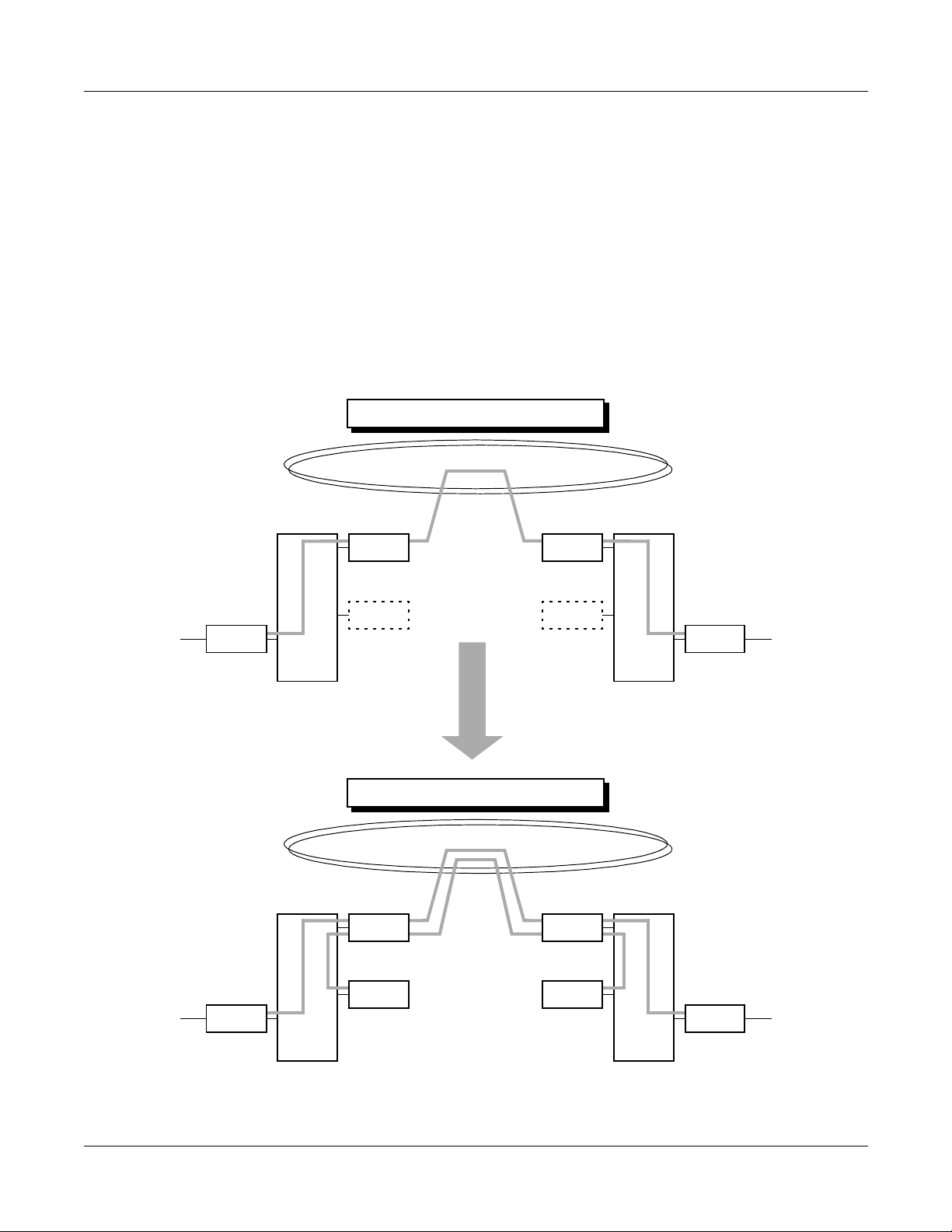
Figure 3-1 Outline of BRI to BRI Connections . . . . . . . . . . . . . . . . . . . . . . . . . . . . . . . . . . . . . . . 115
Figure 3-2 Event Based CCIS Programming Summary . . . . . . . . . . . . . . . . . . . . . . . . . . . . . . . . 116
Figure 3-3 Verification of Connection . . . . . . . . . . . . . . . . . . . . . . . . . . . . . . . . . . . . . . . . . . . . . . 127
Figure 4-1 Mounting Location of Circuit Card . . . . . . . . . . . . . . . . . . . . . . . . . . . . . . . . . . . . . . . . 139
Page iv ND-70919 (E), Issue 1.0
NEAX2000 IVS2 ISDN System Manual
Page 10

LIST OF TABLES
Table Title Page
Table 1-1 Event Based CCIS Feature List . . . . . . . . . . . . . . . . . . . . . . . . . . . . . . . . . . . . . . . . . . 17
Table 1-2 ISDN Card Name and Function . . . . . . . . . . . . . . . . . . . . . . . . . . . . . . . . . . . . . . . . . . 21
Table 1-3 System Capacity for ISDN-PRI . . . . . . . . . . . . . . . . . . . . . . . . . . . . . . . . . . . . . . . . . . 22
Table 1-4 System Capacity for ISDN-BRI . . . . . . . . . . . . . . . . . . . . . . . . . . . . . . . . . . . . . . . . . . 23
Table 1-5 Transmission Characteristics . . . . . . . . . . . . . . . . . . . . . . . . . . . . . . . . . . . . . . . . . . . . 27
Table 1-6 12-Multi Frame Bit Assignment . . . . . . . . . . . . . . . . . . . . . . . . . . . . . . . . . . . . . . . . . . 30
Table 1-7 24-Multi Frame Bit Assignment . . . . . . . . . . . . . . . . . . . . . . . . . . . . . . . . . . . . . . . . . . 32
Table 1-8 Time Slot Assignment of 30DTI . . . . . . . . . . . . . . . . . . . . . . . . . . . . . . . . . . . . . . . . . . 34
Table 2-1 ISDN-PRI Required Equipment . . . . . . . . . . . . . . . . . . . . . . . . . . . . . . . . . . . . . . . . . . 39
Table 2-2 ISDN-BRI Required Equipment . . . . . . . . . . . . . . . . . . . . . . . . . . . . . . . . . . . . . . . . . . 39
Table 2-3 ISDN Terminal Required Equipment . . . . . . . . . . . . . . . . . . . . . . . . . . . . . . . . . . . . . . 40
Table 2-4 Event Based CCIS Required Equipment . . . . . . . . . . . . . . . . . . . . . . . . . . . . . . . . . . . 40
Table 4-1 List of Required Circuit Card . . . . . . . . . . . . . . . . . . . . . . . . . . . . . . . . . . . . . . . . . . . . 140
Table 5-1 Alarm Indications on 24DTI . . . . . . . . . . . . . . . . . . . . . . . . . . . . . . . . . . . . . . . . . . . . . 191
Table 5-2 Alarm Indications on 30DTI . . . . . . . . . . . . . . . . . . . . . . . . . . . . . . . . . . . . . . . . . . . . . 192
Table 5-3 Alarm Indications on 24PRT . . . . . . . . . . . . . . . . . . . . . . . . . . . . . . . . . . . . . . . . . . . . 193
Table 5-4 Alarm Indications on BRT . . . . . . . . . . . . . . . . . . . . . . . . . . . . . . . . . . . . . . . . . . . . . . 194
NEAX2000 IVS2 ISDN System Manual
ND-70919 (E), Issue 1.0
Page v
Page 11

This page is for your notes.
Page vi ND-70919 (E), Issue 1.0
NEAX2000 IVS2 ISDN System Manual
Page 12

INTRODUCTION
Purpose
INTRODUCTION
PURPOSE
This manual describes the hardware installation and programming procedure for the ISDN
service on the NEAX2000 IVS2.
OUTLINE OF THIS MANUAL
This manual contains the following chapters:
CHAPTER 1 GENERAL INFORMATION
This chapter explains the ISDN system outline, the equipment name and function, system
specifications, capacity, and conditions.
CHAPTER 2 INSTALLATION
This chapter explains the hardware installation procedure to provide ISDN interface to the PBX.
CHAPTER 3 SYSTEM DATA PROGRAMMING
This chapter explains the programming procedure to provide the ISDN feature to the PBX.
CHAPTER 4 CIRCUIT CARD INFORMATION
This chapter e xpla ins the mou nting loca tion, the m eaning of lam p indica tions , and the method o f
switch settings of ea ch circuit card f o r the ISDN syst em.
CHAPTER 5 OPERATION TEST
This chapter e xplains the operation t est to be perf ormed after completion of the ISDN install ation.
For fault diagnosis by MAT or CAT, refer to the M ai ntenance Manual.
NEAX2000 IVS2 ISDN System Manual
ND-70919 (E), Issue 1.0 Pa ge 1
Page 13

INTRODUCTION
Reference Manuals
REFERENCE MANUALS
Refe r to the ma nuals during installation:
Command Manual Describes Customer Administration Terminal (CAT)
operation, command function, and setting data required for
programming the system an d Resident System Program.
Office Data Programming Manual Contains the Customer Specification Sheets and Office
Data Programming Sheet s.
Maintenance Manual Describes the maintenance service features and the
recommended troubleshooting proce du re.
Installation Procedure Manual Describes the installation procedure for the PBX system.
CCIS System Manual Describes the installation and programming procedure for
the CCIS system.
Page 2 ND-70919 (E), Issue 1.0
NEAX2000 IVS2 ISDN System Manual
Page 14

CHAPTER 1
GENERAL INFORMATION
This chapter explains the ISDN system outline, the equipment name
and function, system specifications, cap acity, and conditions.
NEAX2000 IVS2 ISDN System Manual
ND-70919 (E), Issue 1.0
Page 3
Page 15
CHAPTER 1 GENERAL INFORMATION
System Outline
SYSTEM OUTLINE
This system can be interfaced with an ISDN with the Primary Rate Interface or the Basic Rate
Interf ace at the reference point S/T and ISDN Terminal.
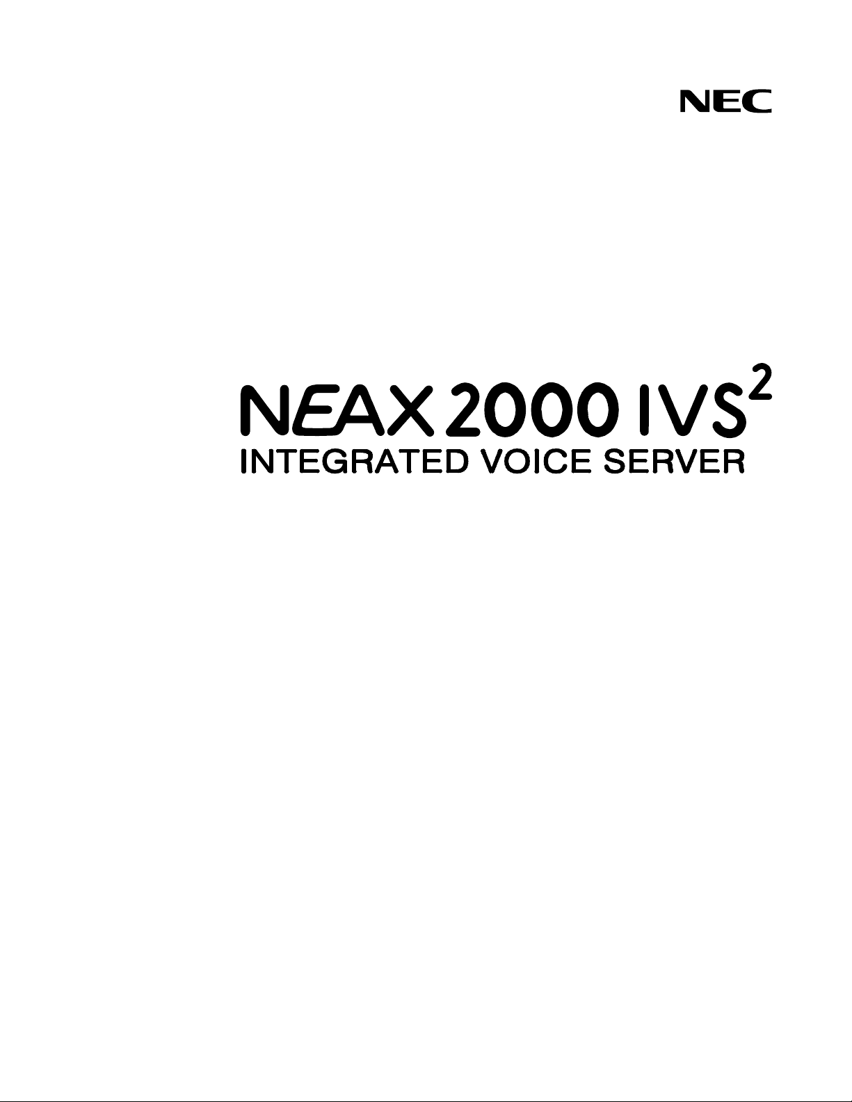
System Outline of ISDN-PRI
The system is configured with a 24/30-channel Digital Tr unk Interface (DTI) for digital network
interface, D Channel Handler (DCH) for receiving/transmitting D channel signaling data from/to
the ISDN exchange. Since the Main Processor (MP) contains Phase Locked Oscillator (PLO),
the system can be synchronized to the ISDN as a clock receiver office.
Figure 1-1 shows the system outline of ISDN-PRI.
Figure 1-1 System Outline of ISDN-PRI
SLT
D
term
LC
DLC
DCH
FP
PBX
TDSW
MP
(PLO)
23B/30B
D
DTI
/PRT
1.5 M/2 M PCM
DIGITAL LINE (23B/30B + D)
CLOCK
SIGNAL
DCH: D Channel Handler
DTI : Digital Trunk Interface
NT1 : Network Termination One
PLO: P hase Locked Oscillator
PRT: P r imary Rate Interface Trunk
NT1
ISDN
NOTE 1: NT1 equipment must be installed in the premise.
NOTE 2: The PRT provides a built-in DCH.
Page 4 ND-70919 (E), Issue 1.0
NEAX2000 IVS2 ISDN System Manual
Page 16
CHAPTER 1 GENERAL INFORMATION
System Outline
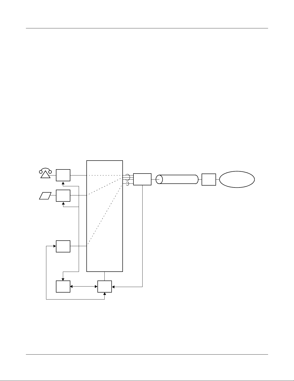
System Outline of ISDN-BRI
The system is configured with a Basi c Rate Interface Trunk (BRT) f or the digital netw ork interface .
Since the MP contai ns PLO, the system can be synchronized to the ISDN as a clock receiver
office.
Figure 1-2 shows the system outline of ISDN-BRI.
Figure 1-2 System Outline of ISDN-BRI
SLT
D
term
LC
DLC
FP
PBX
TDSW
MP
(PLO)
2B
BRT
2-CHANNEL PCM
DIGITAL LINE (2B + D)
D
CLOCK
SIGNAL
BRT: Basic Rate Interface Trunk
NT1: Network Termination One
PLO: Phase Locked Oscillator
NT1
ISDN
NOTE: NT1 equipment must be installed in the premise.
NEAX2000 IVS2 ISDN System Manual
ND-70919 (E), Issue 1.0
Page 5
Page 17
CHAPTER 1 GENERAL INFORMATION
System Outline
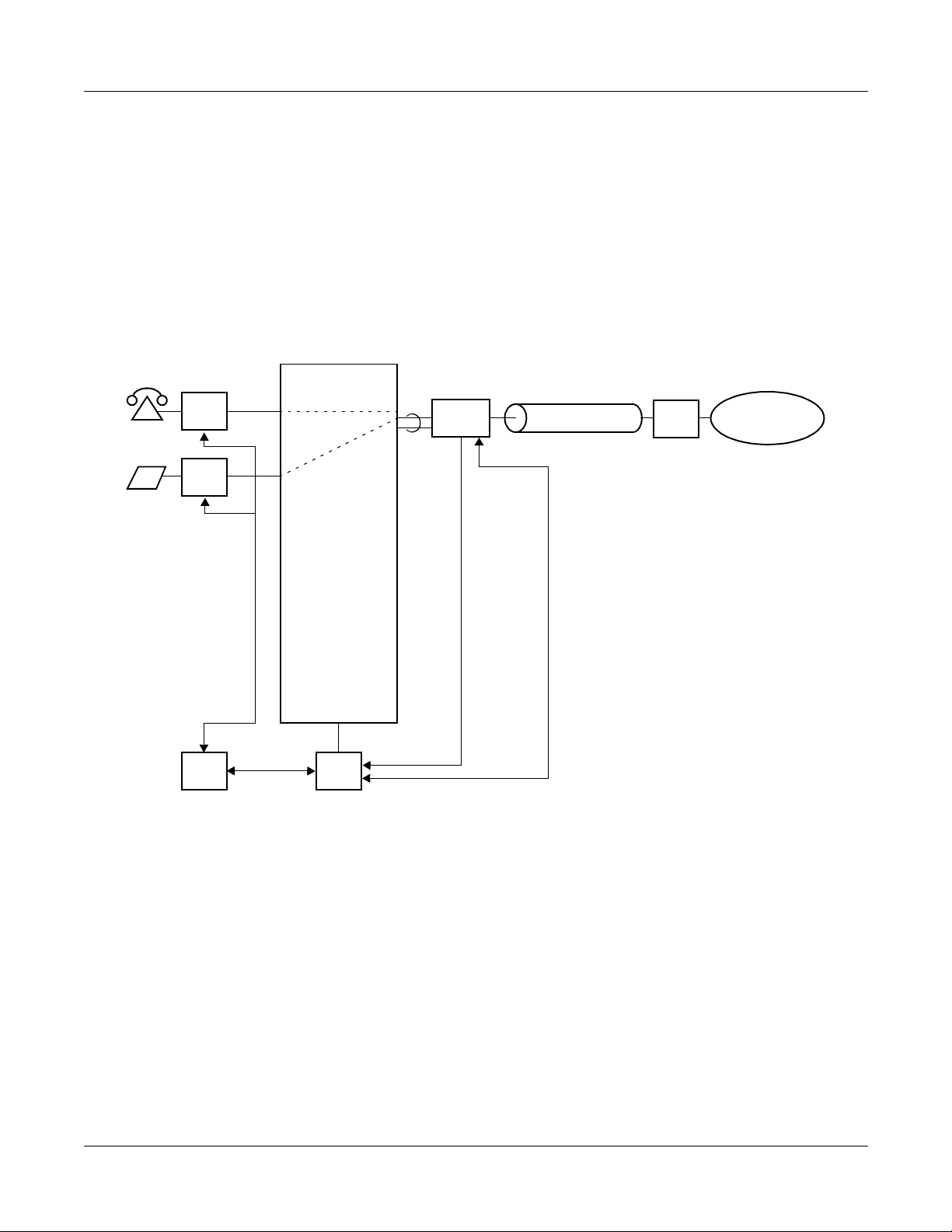
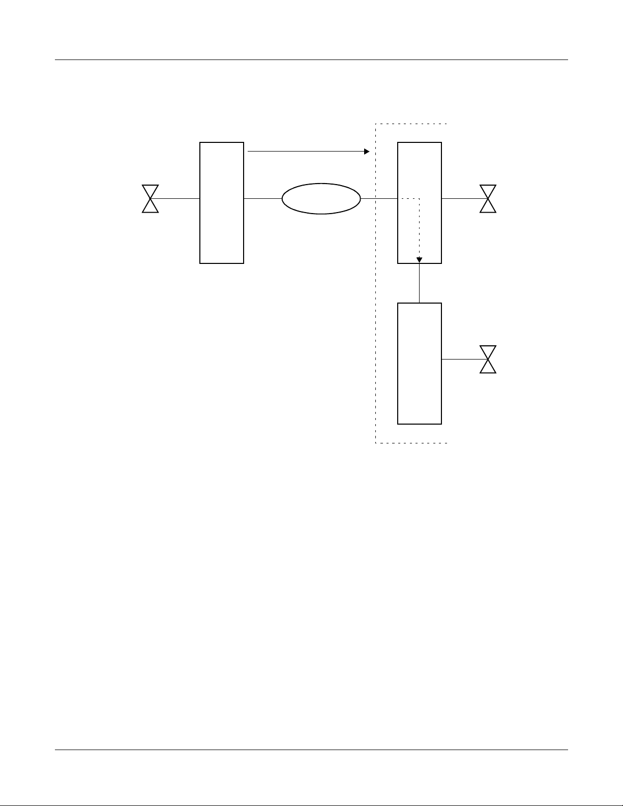
System Outline of ISDN-VPN
The Virtual Private Network (VPN) is a service which provides an interoffice private line via an
ISDN network.
When you dial a station number (Called Par ty Subaddress), the system sends a pre-assigned
office number of a cal led p arty toget her with the Cal led Par ty Suba ddre ss to an I SDN net work .
With this function, an inter o ffi ce call can b e ma de by only dialing a station number (Calle d Party
Subaddress).
Figure 1-3 shows an example of using the VPN.
Figure 1-3 Example of ISDN-VPN (1 of 2)
• When an opposite office can interface with the ISDN network
Calling Party
Dial 1234
PBX
A
0345678910 (Office No.)
1234 (Called Party Subaddress)
ISDN
PBX
B
(034567-8910)
Called Party
Station No. 1234
Page 6 ND-70919 (E), Issue 1.0
NEAX2000 IVS2 ISDN System Manual
Page 18
CHAPTER 1 GENERAL INFORMATION
Figure 1-3 Example of ISDN-VPN (2 of 2)
• When an opposite office cannot interface with the ISDN network
System Outline
Calling Party
Dial 1234
PBX
A
0345678910 (Office No.)
1234 (Called Party Subaddress)
ISDN
PBX
Tie Line
B
(034567-8910)
1234
Station No. 1234
Called Party
C
NEAX2000 IVS2 ISDN System Manual
ND-70919 (E), Issue 1.0
Page 7
Page 19

CHAPTER 1 GENERAL INFORMATION
System Outline
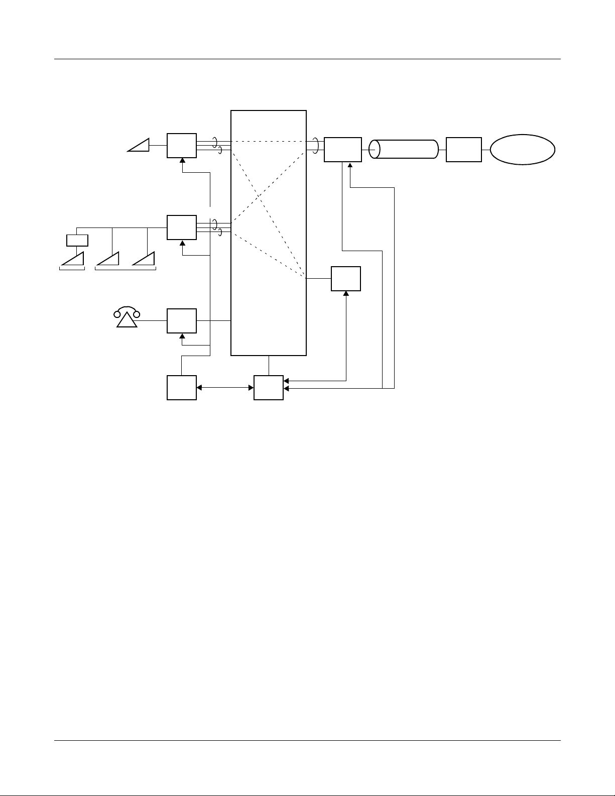
System Outline of ISDN Terminal
The system is configured with an ISDN Line Circuit (ILC) for the line interface of an ISDN
Terminal and an ISDN Channel Handler (ICH) for Layer 2 protocol processing (LAP-D).
Figure 1-4 and Figure 1-5 show the system outline of the ISDN Terminal.
Figure 1-4 System Outline of ISDN Terminal (for ISDN-PRI)
PBX
DTI
CLOCK
SIGNAL
1.5 M/2 M PCM
DIGITAL LINE (23B/30B + D)
NT1 ISDN
• Point to Point
Connection
ISDN
Terminal
(TE)
• Point to Multi-point
Connection
TA
ILC
ILC
2B × 2
2D
2B × 2
2D
23B/30B
/PRT
D
Data
Terminal
ISDN Terminal
(TE)
SLT
LC
DCH
FP
TDSW
MP
(PLO)
8D
NOTE 1: The following connections are only available:
• ISDN Terminal to ISDN Terminal Connection
• ISDN Terminal to ISDN Trunk Connection
• ISDN Trunk to ISDN Terminal Connection
• ISDN Terminal to Single Line Telephone Connection
ICH
DCH : D Channel Handler
DTI : Digital Trunk Interface
ICH : ISDN Channel Handler
ILC : ISDN Line Circuit
LC : Line Circuit
NT1 : Network Termination One
PLO : Phase Locked Osci llator
PRT : Primary Rate Interface Trunk
TA : Terminal Adapter
NOTE 2: NT1 equipment must be installed on the premises.
Page 8 ND-70919 (E), Issue 1.0
NEAX2000 IVS2 ISDN System Manual
Page 20
• Point to Point
Connection
CHAPTER 1 GENERAL INFORMATION
Figure 1-5 System Outline of ISDN Terminal (for ISDN-BRI)
PBX
2-CHANNEL PCM
DIGITAL LINE (2B + D)
NT1
D
ISDN
Terminal
(TE)
ILC
2B × 2
2D
2B
BRT
System Outline
ISDN
• Point to Multi-point
Connection
TA
Data
Terminal
ISDN Terminal
(TE)
SLT
ILC
LC
FP
2B × 2
2D
TDSW
MP
(PLO)
8D
ICH
NOTE 1: The following connections are only available:
• ISDN Terminal to ISDN Terminal Connection (S/T Interface)
• ISDN Terminal to ISDN Trunk Connection (S/T Interface)
• ISDN Trunk to ISDN Terminal Connection (S/T Interface)
• ISDN Terminal to Single Line Telephone Connection
CLOCK
SIGNAL
BRT : Basic Rate Interface Trunk
ICH : ISDN Channel Handler
ILC : ISDN Line Circuit
LC : Line Circuit
NT1 : Network Termination One
PLO : Phase Locked Oscillato r
TA : Terminal Adapter
NOTE 2: NT1 equipment must be insta l le d on the pr em i ses.
NEAX2000 IVS2 ISDN System Manual
ND-70919 (E), Issue 1.0
Page 9
Page 21

CHAPTER 1 GENERAL INFORMATION
System Outline
DTI
The Digital Trunk Interface (DTI) interfaces the PBX directly to 24/30- channe l PCM tr an smissio n
line. The DTI has the following functions:
For 24DTI:
• Unipolar/Bipolar Conversion (AMI Format/B8ZS Format)
• Alarm Detection/Insertion
• Digital PAD on Voice Signal Transmission
• Loop-Back Test (Local/Remote Loop Back)
• Cyclic Redundancy Checking (based on ITU-T Rec. G704)
For 30DTI:
• Unipolar/Bipolar Conversion (HDB3 Format)
• Alarm Detection/Insertion
• Digital PAD on Voice Signal Transmission
• Cyclic Redundancy Checking (based on ITU-T Rec. G704)
For con nections of a 24DTI an d transmission line , twisted-pair cable can be u sed. For co nnection
of a 30DTI and transmission line, either coaxial cable or twisted-pair cable can be used.
DCH
The D Channel Handler (DCH) provides the D Channel signalling interface through the DTI to an
ISDN exchange, and it is re sponsible for signaling between th e PBX and the ISDN exchange
under control of the system MP.
PRT
The Primary Rate Interface Trunk (PRT) provides the ISDN Primary Rate Interface (1.5 Mbps
PCM-23B + D) and a built-in DCH. The PRT has the following functions:
• Unipolar/Bipolar Conversion (AMI Format/B8ZS Format)
• Alarm Detection/Insertion
• Digital PAD on Voice Signal Transmission
• Loop-Back Test (Local/Remote Loop Back)
• Cyclic Redundancy Checking (based on ITU-T Rec. G704)
For connections of PRT and transmission line, twisted-pair cable can be used.
NOTE: ISDN requires B8ZS line coding with Extended Superframing (ESF) Format.
Page 10 ND-70919 (E), Issue 1.0
NEAX2000 IVS2 ISDN System Manual
Page 22

CHAPTER 1 GENERAL INFORMATION
System Outline
BRT
The Basic Rate Interface Trunk (BRT) provides one or two physical interface to the ISDN-Basic
Rate Interface service (144 Kbps PCM-2B + D).
The BRT has the following functions:
• Unipolar/Bipolar Conversion (AMI Format) (S/T Interface) / B8ZS
• Signaling Insertion/Extraction
• Frame Synchroniza ti on
• Digital PAD on Voice Signal Transmission
For connections of BRT and transmission line, twisted-pair cables can be used.
NEAX2000 IVS2 ISDN System Manual
ND-70919 (E), Issue 1.0
Page 11
Page 23
CHAPTER 1 GENERAL INFORMATION
System Outline
PLO
The Phase Locked Oscillator (PLO) equipped on the MP card synchronizes the system to an
ISDN clock.
The PLO generates the cloc k signals acco rding to the source cloc ks receiv e d from network. The
source clock signals are extracted at DTI/BRT/PRT cards and supplied to the PLO. Two clock
routes are available; one is Route 0 that receives clock signals from DTI0/BRT0/PRT0, and the
other is a standby Route 1 (DTI1/BRT1/P RT1) that receives clock signals when no clock signals
appear on Rout e 0. When no cl ock signals come from either Route 0 o r Rout e 1 , the PLO keeps
generating the clock signals at the frequency of the last source clock. The PLO can receive
differ ent frequencies of source clocks from Route 0 and Route 1.
Figure 1-6 shows an example of clock supply route.
Figure 1-6 Clock Supply Route
TDSW
PLO
PBX
NOTE
DTI0/BRT0
/PRT0
DTI1/BRT1
/PRT1
ISDN
: CLOCK SIGNAL SUPPLY ROUTE 0
: CLOCK SIGNAL SUPPLY ROUTE 1
NOTE: DTI0/BRT0/PRT0 and DTI1/BRT1/PRT1 must be mounted in PIM0.
Page 12 ND-70919 (E), Issue 1.0
NEAX2000 IVS2 ISDN System Manual
Page 24

CHAPTER 1 GENERAL INFORMATION
System Outline
ICH
The ISDN Channe l Hand ler (ICH) pro vides the D channel si gnaling interf ace an d controls an ILC
(Layers 2 and 3).
ILC
The ISDN Line Circuit (ILC) provides a physical interface to the ISDN Ter minal. The interface
provides for a maximum of two line circuits.
NEAX2000 IVS2 ISDN System Manual
ND-70919 (E), Issue 1.0
Page 13
Page 25
CHAPTER 1 GENERAL INFORMATION
Outline of Event Based CCIS
OUTLINE OF EVENT BASED CCIS
Event Based CCIS allows a PBX customer who does not have tie lines to use the various
Common Channel Interoffice Sig naling (CCIS) feature by using ISDN lines as CCIS virtual tie
lines. F o r the PBX custo mer w ho usua lly has l o w t raffi c , Event Based CCIS is av a ilab l e be twee n
NEC NEAX PBXs.
Figure 1-7 shows the system outline of Event Based CCIS.
Figure 1-7 System Outline of Event Based CCIS
REGULAR ISDN CONNECTION
ISDN NETWORK
LC/TRK
PBX
NEC PBX
DTI/BRT
/PRT
CCH
EVENT BASED CCIS CONNECTION
ISDN NETWORK
DTI/BRT
/PRT
DTI/BRT
/PRT
CCH
DTI/BRT
/PRT
PBX
LC/TRK
NEC PBX
CCH
LC/TRK
NEAX2000 IVS2 ISDN System Manual
Page 14 ND-70919 (E), Issue 1.0
CCH
LC/TRK
Page 26
CHAPTER 1 GENERAL INFORMATION
Outline of Event Based CCIS
Common Channel and Voice Channel Link Control
When the call is a regular ISDN call or when there is no call on the PBX, the common signaling
channel and the voice channel for the virtual tie lines are disconnected.
If the virtual tie lines are all busy or when the vi rtual tie lines cannot be connected due to a line
fault, a call is transmitted to the opposite office via ISDN network as a regular ISDN call, not as
a CCIS call.
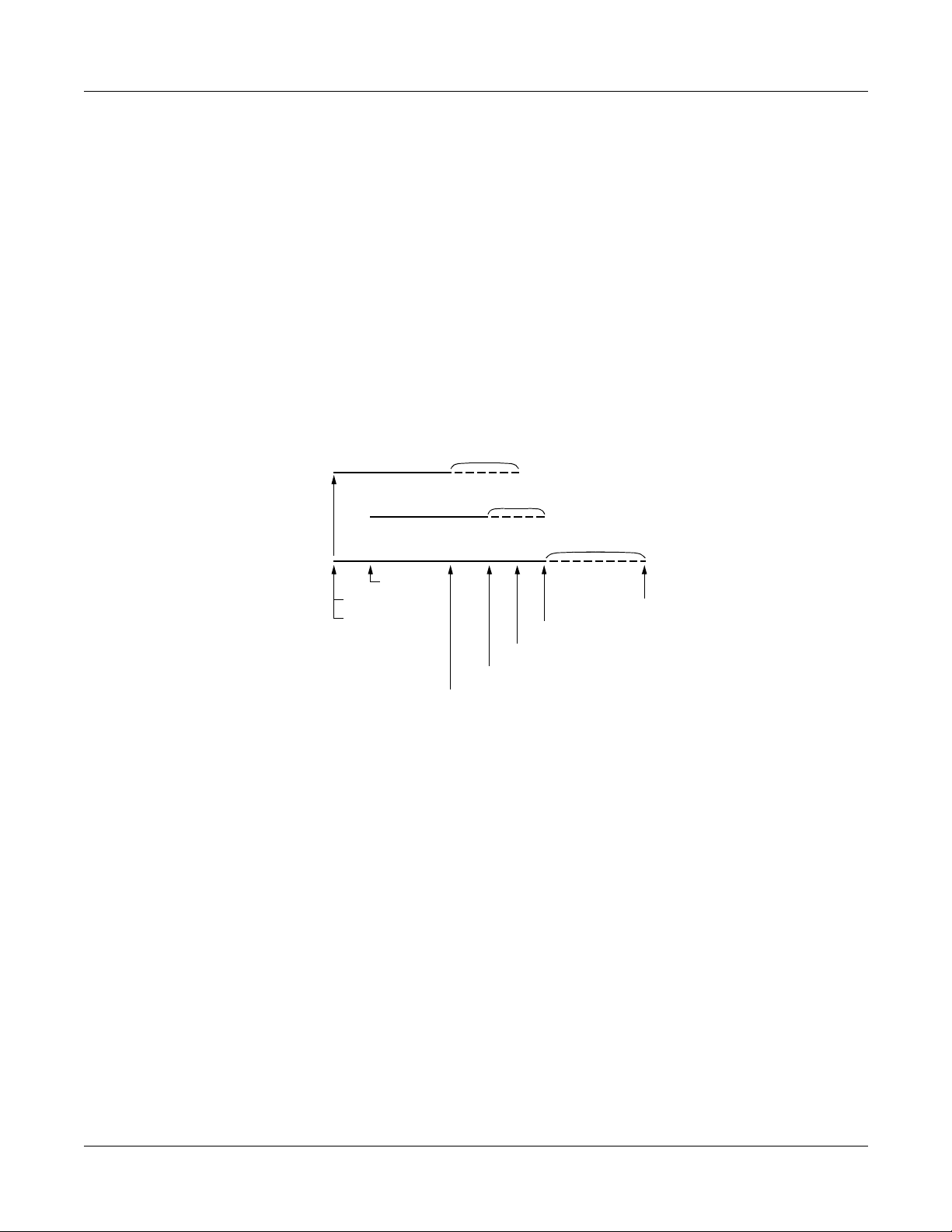
When a predetermined time passes after all calls finish, the voice channels and common
signaling channel are released and the CCIS link is disconnected. The release timer is set by
system data programming for the common signaling channel and voice channels.
Figure 1-8 Release Timing of Virtual Tie Line and CCIS Link
n sec.
Voice ch 1 (B2)
n sec.
Voice ch 2 (B3)
m sec.
CCIS link (B1)
n, m: Release timer
2.4 seconds-max. 28 minutes
VT: Virtual Tie Line
Set VT (B3)
Set VT (B1)
Set VT (B2)
Release VT (B3)
Release VT (B2)
Release CCIS (B3)
Release CCIS (B2)
Release VT (B1)
NEAX2000 IVS2 ISDN System Manual
ND-70919 (E), Issue 1.0
Page 15
Page 27
CHAPTER 1 GENERAL INFORMATION
Outline of Event Based CCIS
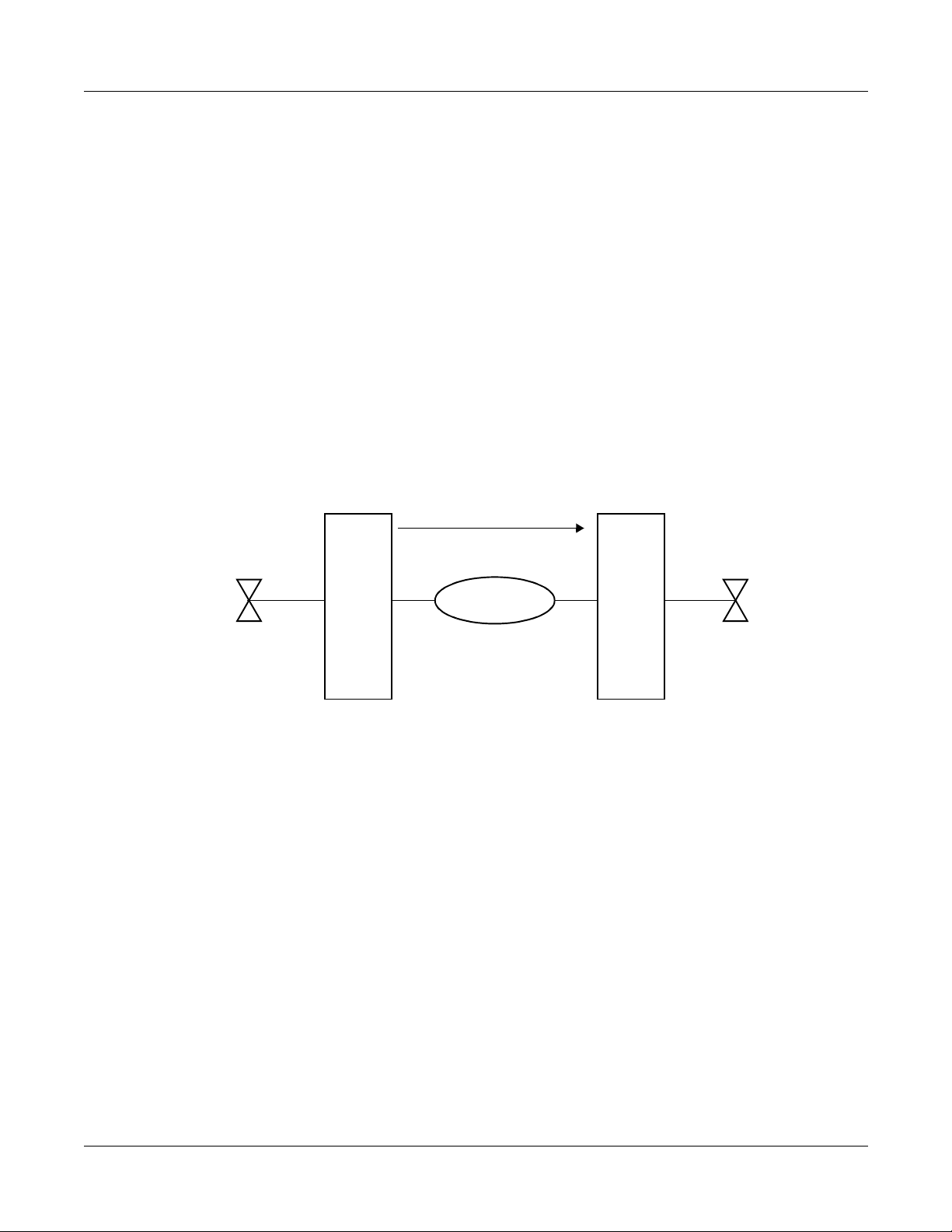
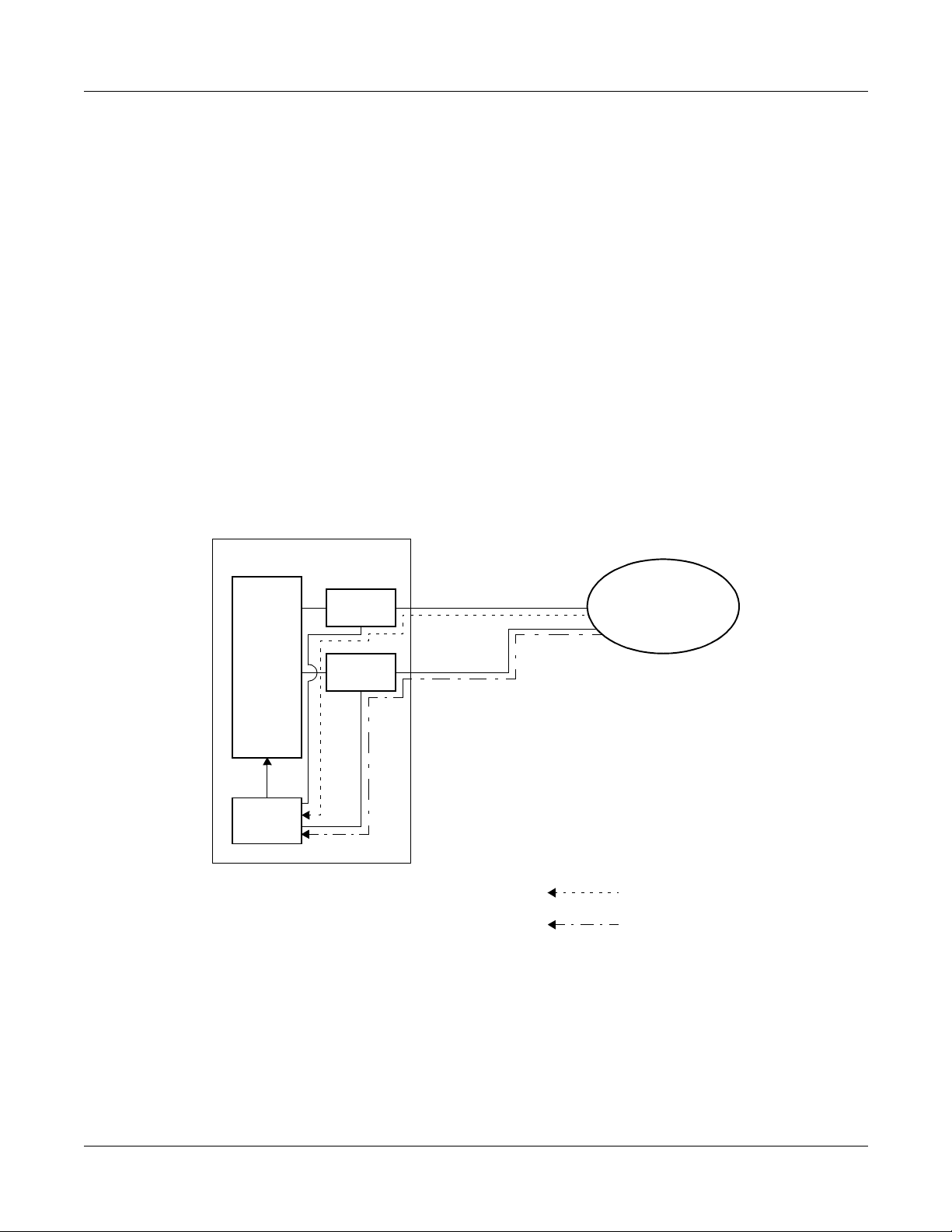
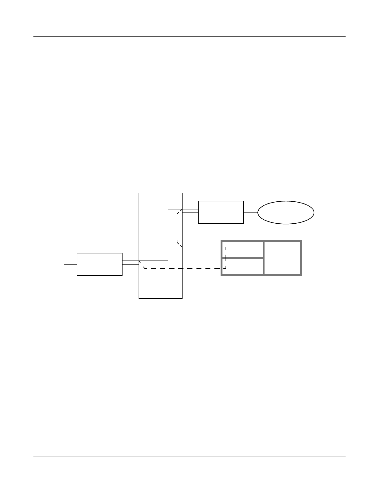
For Event Based CCIS, the virtual trunks are used as a No. 7 CCIS trunk.
Virtual Trunk:
The virtual trunk consists of a Home-Side Trunk and a Mate-Side Trunk. The Home-Side
Trunk is connected to the st ation side, and the Mate-Side Trunk is connected to the network
side of the PBX virtually.
The virtual trunks do not exist actually, but are handled as a No . 7 CCIS trunk by the syst em,
for system data. ISDN subaddress or ISDN indial number is use d to notify the CCIS channel
number for virtual tie line and establish a CCIS link and individual voice links between
offices.
Figure 1-9 Virtual Trunk
TDSW
LC/TRK
DTI/BRT/PRT
MATE-SIDE
HOME-SIDE
ISDN
VIRTUAL
TRUNK
CCH Card:
The CCH card is used to handl e the common channel signaling.
DTI/BRT/PRT Card:
The system uses the same interface trunk for regular ISDN connection an d the virtual tie
line connection on Event Based CCIS.
ISDN Protocol Analyzer:
For ISDN PRI, the protocol analyze r must be able to supp ort ISDN exch ange, such as AT&T ,
Nortel. For North America, it must support National ISDN 2 (NI-2) protocols.
For ISDN BRI, the protocol analyzer must be an S/T interface. For North America, it must
support National ISDN 1 (NI-1) protocol.
Both analyzers must be capa ble of collecting Layer 2 and Layer 3 (Q921 & Q931 )
information.
Page 16 ND-70919 (E), Issue 1.0
NEAX2000 IVS2 ISDN System Manual
Page 28

CHAPTER 1 GENERAL INFORMATION
Outline of Event Based CCIS
Event Based CCIS Feature List
Table 1-1 Event Based CCIS Feature List
: Available
X
: Not available
–
SERVICE FEATURE AVAILABILITY REMARKS
Attendant Camp-On w i th Tone Indication- C CIS X
Attendant Contr oll ed Co nference-CCIS X NOTE 4
Brokerage-Hot-Line-CCIS X
Busy Verification-CCIS X
Call Back-CCIS X
Call Forwarding-All Calls-CCIS X
Call Fo rwarding-Busy Line-CCIS X
Call Fo rwarding-Don’t Answer - C C IS X
Call Fo rwarding-Intercept-CCIS X
Call Forwarding-Override-CCIS X
Calling Name Display-CCIS X
Calling Number Display-CCIS X
Call Transfer-All Calls-CCIS X
Call Transfer-Attend an t- C CI S X
Centralized Billing-CCIS X NOTE 2
Centralized Day/Night Mode Change-CCIS –
Consultation Hold-All Calls-CCIS X
Deluxe Traveling Class Mark-CCIS X
Dial Access to Attendant-CCIS X
Direct-in Termination-CCIS X
Distinctive Ringing-CCIS X
Do Not Disturb-CCIS X
Dual Hold-CCIS X
Elapsed Time Display-CCIS X
Flexible Numbering of Station-CCIS X
NEAX2000 IVS2 ISDN System Manual
ND-70919 (E), Issue 1.0
Page 17
Page 29

CHAPTER 1 GENERAL INFORMATION
Outline of Event Based CCIS
Table 1-1 Event Based CCIS Feature List (Continued)
: Available
X
: Not available
–
SERVICE FEATURE AVAILABILITY REMARKS
Hands-Free-Answer Back-CCIS X
House-Phone-CCIS X
Hot Line-CCIS X
Incoming Call Identification-CCIS X
Individual Attendant Access-CCIS X NOTE 5
LDN Night Connection-CCIS X
Link Alarm Display-CCIS –
Message Waiting Lamp Setting-Attend ant-CCIS X NOTE 3
Message Waiting Lamp Setting-Station-CCIS X NOTE 3
Miscellaneous Trunk Access-CCIS X
Miscellaneous Trunk Restriction-CCIS X
Multiple Call Forwarding-All Calls-CCIS X
Multiple Call Forwarding-Busy Line-CCIS X
Multiple Call Forwarding-Don’t Answer-CCIS X
Night Connection Fixed-CCIS X
Night Connection Flexible-CCIS X
Outgoing Trunk Queuing-CCIS –
Paging Access-CCIS X
Restriction from Outgoing Calls-CCIS X
Single Digit Station Calling-CCIS X
Station Controll ed Confer ence-CCIS X NOTE 4
Station to Station Ca lli n g- C C IS X
Station to Station Calling-Operator Assi stance-CCIS X
Toll Restriction-3/6 Digit-CCIS X
Trunk Answer from Any Station-CCIS X
Trunk to Trunk Restriction-CCIS X
Page 18 ND-70919 (E), Issue 1.0
NEAX2000 IVS2 ISDN System Manual
Page 30

CHAPTER 1 GENERAL INFORMATION
Outline of Event Based CCIS
Table 1-1 Event Based CCIS Feature List (Continued)
: Available
X
: Not available
–
SERVICE FEATURE AVAILABILITY REMARKS
Uniformed Numbering Plan-CCIS X
Voice Call-CCIS X
Voice Mail Integration-CCIS X
NOTE 1: The voice channel and the common signaling channel keep connecting after the calls
finish according to the release timer data. Therefore, while the CCIS link is kept up by
the timer, the features are available.
NOTE 2: The billing information is sent while the CCH link is connected. If the sending of billing
information has failed, it is sent again when a new CCH link is established by the next
call.
NOTE 3: As a remote office, this feature is available on NEAX2000 IVS2/7400ICS M100M X.
NOTE 4: An attendant/extension of the NEAX2000 IVS2/7400ICS M100MX cannot be a
conference leader.
NOTE 5: This service is available when the Attendant Console is provided at the IMX office on
the network.
NEAX2000 IVS2 ISDN System Manual
ND-70919 (E), Issue 1.0
Page 19
Page 31

CHAPTER 1 GENERAL INFORMATION
Outline of Event Based CCIS
Event Based CCIS Service Conditions
• Event Based CCIS connection is available between NEC N EAX PBXs.
• The maximum number of the virtual tie lines is 16 channels per one system, including both
common signaling channels and voice channels.
• Th is feature supports voice calls only. Sup ported objects at PBX transmission side: single
line telephone, D
• The data calls are transmitted via the regula r ISDN network.
• The number of originating calls from the ISDN trunk is counted as Peg Count when using
the ISDN line for the virtual tie line by route basis.
• Billing information of the virtual tie line using the ISDN line can be treated as regular tie line
calls.
• Billing information of the virtual tie line using the ISDN line can be treated on tandem calls.
term
, DID/E&M/Ring Down (analog/T1/E1) tandem calls.
• The voice channel of the virtual tie line is released after the call is finished.
The common signaling channel of virtual tie line is released after all calls on voice channels
are finished. The release timer is determined by system timer programming for the v oice
channels and the common si gn al i ng cha nne l s.
• The ISDN line used for the virtual tie line can also be used as a regular ISDN line.
The trunk route used for the virtual tie line can be distinguished from the regular ISDN line
by assigning different LCR data in system programming.
Page 20 ND-70919 (E), Issue 1.0
NEAX2000 IVS2 ISDN System Manual
Page 32

CHAPTER 1 GENERAL INFORMATION
CARD NAME AND FUNCTION
Table 1-2 shows the circuit card names and function for ISDN.
Table 1-2 ISDN Card Name and Function
Card Name and Function
CARD NAME
FUNCTIONAL
FUNCTION
NAME
PN-BRTA BRT 1-line Basic Rate (2B + D) Interface Trunk Card
Accommodates one 2-channel PCM digital lines
PN-2BRTC BRT 2-line Basic Rate (2B + D) Interface Trunk Card
Accommodates two 2-channel PCM digital lines
PN-24DTA-C DTI Digital Trunk Interface (23B + D, 1.5 Mbps) Card
Accommodates 24-channel PCM digital lines
PN-30DTC-A DTI Digital Trunk Interface (2 Mbps) Card
Accommodates 30-channel PCM digital lines
PN-2ILCA ILC 2-line ISDN Line Circuit Card
Provides a physical interface to ISDN Terminals
Occupies 8 time slots per one card
PN-24PRTA PRT ISDN Primary Rate (23B + D) Interface Card
Provided a built-in D-channel Handler (DCH)
PN-SC00 CCH Common Channel Handler Card
Transmits/receives signals on the common signaling
channel of No. 7 CCIS
PN-SC01 DCH D-channel Handler Card
Trans mits/receives signals on t he D-c hannel of ISDN
Primary Rate (23B + D) interface or WCS Roaming
interface
PN-SC03 ICH ISDN-channel Handler Card
Provides the D-channel signaling interface and controls
max. four ILC cards (Layers 2 and 3)
NEAX2000 IVS2 ISDN System Manual
ND-70919 (E), Issue 1.0
Page 21
Page 33

CHAPTER 1 GENERAL INFORMATION
System Capacity
SYSTEM CAPACITY
System Capacity for ISDN-PRI
Table 1-3 System Capacity for ISDN-PRI
CAPACITY
DESCRIPTION
24DTI 24PRT 30DTI
DTI Card 8 – 4
DCH Card 8 – 4
Trunks for DTI 192 – 124
PRT Card – 8 –
Trunks for PRT – 192 –
ISDN Routes 8 8 4
ICH Card 12 12 12
ILC Card 48 48 48
Port per DTI Card 24 – 32
Port per DCH Card 1 – 1
Port per PRT Card – 24 + 1 (DCH) –
Port per ICH Card 4 4 4
Port per ILC Card 8 8 8
Page 22 ND-70919 (E), Issue 1.0
NEAX2000 IVS2 ISDN System Manual
Page 34

CHAPTER 1 GENERAL INFORMATION
System Capacity for ISDN-BRI
Table 1-4 System Capacity for ISDN-BRI
DESCRIPTION CAPACITY
BRT Card (BRTA/2BRTC) 12/24
Trunks for BRT (BRTA/2BRTC) 24/96
ICH Card 12
ILC Card 48
Port per BRT Card (BRTA/2BRTC) 2/4
Port per ICH Card 4
Port per ILC Card 8
System Capacity
NEAX2000 IVS2 ISDN System Manual
ND-70919 (E), Issue 1.0
Page 23
Page 35

CHAPTER 1 GENERAL INFORMATION
System Conditions
SYSTEM CONDITIONS
Time Slot Assignment Condition
As shown in Figu re 1-10, the 30D TI/DCH/ICH/B R T card uses th e time slot on the basic High wa y
4. Therefore, the total number of time slots for all 30DTI/DCH/ICH/BRT cards must be 128 time
slots or less including all other application processor cards, which use Highway 4.
The 24DTI/PRT card can use the time slot on both the basic and expanded Highway 4 and 6.
Therefore, the total number of time slots for all 24DTI/PRT cards must be 256 time slots or less.
Figure 1-10 Accommodation of DTI/DCH/ICH/BRT/PRT into TDSW
FOR L/T CARDS: MAX. 512 TIME SLOTS PER SYSTEM
FP0
FP1
FP2
FP3
DTI
BRT
DCH
HW4
TDSW (1024 TIME SLOTS)
HW6
FOR BASIC HIGHWAY4: MAX. 128 TIME SLOTS PER SYSTEM
FOR EXPANDED HIGHWAY6: MAX. 128 TIME SLOTS PER SYSTEM
ICH
PRT
DTI
MAX. 128 TIME SLOTS
MAX. 128 TIME SLOTS
MAX. 128 TIME SLOTS
MAX. 128 TIME SLOTS
30DTI: MAX. 31 TIME SLOTS/CARD
MAX. 2 TIME SLOTS/CARD (BRTA)
MAX. 4 TIME SLOTS/CARD (2BRTC)
1 TIME SLOT/CARD
1 TIME SLOT/CARD (SC02)
4 TIME SLOTS/CARD (SC03)
25 TIME SLOT/CARD
24DTI: MAX. 24 TIME SLOTS/CARD
FOR AP CARDS: MAX. 256 TIME SLOTS PER SYSTEM
Page 24 ND-70919 (E), Issue 1.0
NEAX2000 IVS2 ISDN System Manual
Page 36

CHAPTER 1 GENERAL INFORMATION
System Conditions
Time Slot Allocation for DTI/PRT/DCH Card
On each DTI/PR T card, the system recogniz es the lowe st and highest channel n umbers to which
trunk numbers have been assigned and allocates time slots to all the channels within them. If
trunk numbers are assigned to discontinuous channels in this case, the system also allocates
time slots to channels not assigned.
For example, in Figure 1-11, even when Channel 1 through Channel 10 have been assigned by
the system data programming (CM07 YY=01) except Channel 5, the system allocates a total of
10 time slots for all 10 channels. Therefore, to avoid allocation of unnecessary time slots, it is
recommended that consecutive channels are assigned on each DTI/PRT card.
In the case of the DCH card, one time slot is allocated for setting up a fixed path between the DTI
and the DCH by assigning Channel 16 of the DTI as the D Channel.
Figure 1-11 Time Slot Allocation for DTI
10
CH0
DXXX
9
6
5
4
1
DXXX
DXXX
NONE
DXXX
DXXX
NONE
HIGHEST CHANNEL
10 TIME SLOTS ARE
ALLOCATED EVEN
WHEN CH5 IS NOT
ASSIGNED.
LOWEST CHANNEL
NEAX2000 IVS2 ISDN System Manual
ND-70919 (E), Issue 1.0
Page 25
Page 37

CHAPTER 1 GENERAL INFORMATION
System Conditions
Line Distance Between PBX and NT1/ISDN Terminal
Figure 1-12 shows the line distance between PBX and NT1 and the line distance between PBX
and ISDN Terminal.
Figure 1-12 Line Distance Between PBX and NT1/ISDN Terminal
(A)
(B)
No. 1 – No. 8
Max. 50 m
(164 ft.*)
(C)
No. 1 – No. 8
Max. 600 m
(1965 ft.*)
MDF
Max. 400 m
(1310 ft.*)
Max. 150 m
(491 ft.*)
ILC
ILC
ILC
PBX
BRT NT1
DTI/PRT NT1
Max. 1000 m
(3280 ft.*)
TO ISDN
TO ISDN
Max. 200 m
(655 ft.**)
: ISDN Terminal
NT1 : Network Termination One
(A) : Point to Point Connection
(B) : Point to Multipoints Connection
(Extended Passive Bus)
(C) : Point to Multipoints Connection (Sho rt
Distance Passive Bus)
NOTE 1: The line dist ance mark ed by * shows the value when the 0.5φ twisted-pair ca ble
is used.
NOTE 2: The line distance marked by ** shows the value w hen the 0.65φ twisted-pair cab le
is used.
Page 26 ND-70919 (E), Issue 1.0
NEAX2000 IVS2 ISDN System Manual
Page 38

CHAPTER 1 GENERAL INFORMATION
DTI SPECIFICATIONS
Transmission Characteristics
Table 1-5 Transmission Characteristics
CHARACTERISTICS 24-CHANNEL 30-CHANNEL
(1) Output
DTI Specifications
• Line Rate
• Line Code
• Line Impedance
• Puls e Amplitude
1.544 Mbps ± 50 ppm
AMI with ZCS/B8ZS*
100 ohms
3 volts ± 0.6 volts
(Base to Peak)
• Pulse Width
324 ns ± 30 ns
* AMI : Alternate Mark Inversion
ZCS : Zero Code Suppression
B8ZS : Bipolar Eight Zero Sub s ti tut io n
2.048 Mbps ± 50 ppm
HDB3 (High Density Bipolar 3)
75 ohms
(Coaxial Cable)
120 ohms
(Twisted-Pair Cable)
2.37 volts nominal
(Coaxial Cable)
3 volts nominal
(Twisted-Pair Cable)
244 ns nominal
NEAX2000 IVS2 ISDN System Manual
ND-70919 (E), Issue 1.0
Page 27
Page 39

CHAPTER 1 GENERAL INFORMATION
DTI Specifications
Table 1-5 Transmission Characteristics (Continued)
CHARACTERISTICS 24-CHANNEL 30-CHANNEL
(2) Input
• Line Rate
• Puls e Amplitude
(Base to Peak)
• F rame Synchronization Pattern
• Input Jitter
• Wander
• Cable Length from PBX to NT1
1.544 Mbps ± 200 bps
(130 ppm)
1.5 volts – 3 volts
001011 (24MF)
ITU-T Fig. 1/G743
+138U1, –193UI
or
–138UI, +193UI
Max. 200 m (655 ft.)
(with 0.65φ (22 ABAM)
twisted-pair cable)
2.048 Mbps ± 50 ppm
1.5 volts – 2.7 volts
(Coaxial Cable)
1.5 volts – 3.3 volts
(Twisted-Pair Cable)
ITU-T Fig. 1/G743
ITU-T G823
Max. 400 m
(with 0.65φ twisted-pair cable)
Page 28 ND-70919 (E), Issue 1.0
NEAX2000 IVS2 ISDN System Manual
Page 40

CHAPTER 1 GENERAL INFORMATION
DTI Specifications
Frame Configuration of 24DTI
According to the AT&T Specifications for 24-Channel transmission, there are two types of frame
configurations: 12-Multi Frame and 24-Multi Frame.
(1) 12-Multi Frame
The frame has 12-Mu lti F rames, and each Multi frame has a 24 -Channel PCM signal (8 bits/
channel) and an S bit (Superframe Bit). Figure 1-13 shows the frame configuration, and
Table 1-6 shows frame bit assignment.
Figure 1-13 DTI Frame Configuration (12-Multi Frame)
S
CH1
11234567812345678
FRAME 1 FRAME 2 FRAME 3 FRAME 12
125 ms
CH2
CH3
12345678
12345678
S: Superframe Bit
CH24
NEAX2000 IVS2 ISDN System Manual
ND-70919 (E), Issue 1.0
Page 29
Page 41

CHAPTER 1 GENERAL INFORMATION
DTI Specifications
Table 1-6 12-Multi Frame Bit Assignment
S BIT
FRAME No.
TERMINAL SYNCHRONIZATION
SIGNAL SYNCHRONIZATION
(FT)
11
20
30
40
51
61
70
81
91
10 1
11 0
12 0
(FS)
* The S-bit is the first bit in each frame.
* Frames are repeated in the order shown above .
* Frames 6 and 12 become signal frames.
Page 30 ND-70919 (E), Issue 1.0
NEAX2000 IVS2 ISDN System Manual
Page 42

CHAPTER 1 GENERAL INFORMATION
DTI Specifications
(2) 24-Multi Frame
This configuration has 24-Multi Frames and each Multi frame has a 24-Channel PCM signal
(8 bits/channel) and an S bi t (Sup er frame Bit). Figure 1-14 shows the frame configuration,
and Table 1-7 shows frame bit assignment.
Figure 1-14 DTI Frame Configuration (24-Multi Frame)
S
CH1
11234567812345678
FRAME 1 FRAME 2 FRAME 3 FRAME 24
125 ms
CH2
CH3
12345678
12345678
S: Superframe Bit
CH24
NEAX2000 IVS2 ISDN System Manual
ND-70919 (E), Issue 1.0
Page 31
Page 43

CHAPTER 1 GENERAL INFORMATION
DTI Specifications
Table 1-7 24-Multi Frame Bit Assignment
S BIT
FRAME No.
SYNCHRONIZATION
FRAME
4 Kbps DATA LINK CRC
1m
2CB1
3m
40
5m
6CB2
7m
80
9m
10 CB3
11 m
12 1
13 m
14 CB4
15 m
16 0
17 m
18 CB5
19 m
20 1
21 m
22 CB6
23 m
24 1
* The S-bit is the first bit in each frame.
* Frames are repeated in the order shown above .
* Frames 6, 12, and 24 become signal frames.
* “m” in the “4 Kbps Data Link” column means that the frame is usually assigned to 1.
Page 32 ND-70919 (E), Issue 1.0
NEAX2000 IVS2 ISDN System Manual
Page 44

CHAPTER 1 GENERAL INFORMATION
DTI Specifications
Frame Configuration of 30DTI
Based on 30-channel transmission method of ITU-T Specification, the frame configuration
consists of 16-multi fra m e, each frame ha ving 32 ti m e slots.
Figure 1-15 shows the frame configuration, and Table 1-8 shows the details of time slot
assignment.
Figure 1-15 Frame Configuration of 30DTI
TS0 TS1 TS2
FRAME 0 FRAME 1 FRAME 2 FRAME 3
125 µsec
TS15 TS16 TS17
FRAME 14
TS30
FRAME 15
TS31
NEAX2000 IVS2 ISDN System Manual
ND-70919 (E), Issue 1.0
Page 33
Page 45

CHAPTER 1 GENERAL INFORMATION
DTI Specifications
Table 1-8 Time Slot Assignment of 30DTI
TIME
SLOT No.
TS0 Frame Alignment Signal (FAS)
TS1
~
TS15
TS16 D Channel Signaling
TS17
~
Voice Channel (B channel)
Voice Channel (B channel)
EVEN No. FRAME ODD No. FRAME
bb
01 234 5 6 7
X0011011
FAS
CRC BIT
CH1
~
CH15
CH17
~
bb
01 234 5 6 7
X1X11111
REMOTE ALARM
CRC BIT
0: NORMAL
1: FRAME LOSS
TS31
CH31
Page 34 ND-70919 (E), Issue 1.0
NEAX2000 IVS2 ISDN System Manual
Page 46

CHAPTER 2
INSTALLATION
This chapter explains th e hardware install ation procedure to provide
ISDN interface to the PBX.
NEAX2000 IVS2 ISDN System Manual
ND-70919 (E), Issue 1.0
Page 35
Page 47

CHAPTER 2 INSTALLATION
Precautions
PRECAUTIONS
Static Electricity Guard
You must wear a grounded wrist strap to protect circuit cards from static electricity.
Figure 2-1 Static Electricity Guard (1 of 2)
• WHEN PLUGGING/UNPLUGGING A CIRCUIT CARD
PBX
WRIST STRAP
• WHEN HOLDING A CIRCUIT CARD
FRAME GROUND SCREW
NEVER TOUCH THE COMPONENTS OR
SOLDERED SURFACE WITH BARE HANDS.
CARD FRONT
Page 36 ND-70919 (E), Issue 1.0
NEAX2000 IVS2 ISDN System Manual
Page 48

Figure 2-1 Static Electricity Guard (2 of 2)
• WHEN MAKING A SWITCH SETTING ON A CIRCUIT CARD
CIRCUIT
CARD
WEAR A WRIST STRAP AND PERFORM
THE WORK ON A GROUNDED
CONDUCTIVE WORK SURFACE.
• WHEN CARRYING A CIRCUIT CARD
CHAPTER 2 INSTALLATION
Precautions
CIRCUIT
CARD
CONDUCTIVE
POLYETHYLENE
BAG
WHEN CARRYING A CIRCUIT CARD
AROUND, KEEP THE CARD IN A
CONDUCTIVE POLYETHYLENE BAG.
The mark shown below is attached to the sheet for the work in which circuit cards are handled.
When engaging in such work, the installer must be careful not to cause damage by static
electricity.
ATTENTION
Contents
Static Sensitive
Handling
Precautions Required
NEAX2000 IVS2 ISDN System Manual
ND-70919 (E), Issue 1.0
Page 37
Page 49

CHAPTER 2 INSTALLATION
Precautions
CAUTION
You must hold the edge of a circuit card when plugging or unplugging the circuit card. If you
touch another area, you may be exposed to hazardous voltages.
PBX
NEVER TOUCH THE COMPONENTS
OR SOLDERED SURFACE WITH
BARE HANDS.
CARD FRONT
Page 38 ND-70919 (E), Issue 1.0
NEAX2000 IVS2 ISDN System Manual
Page 50

CHAPTER 2 INSTALLATION
Required Equipment
REQUIRED EQUIPMENT
ISDN-PRI Required Equipment
Ta b l e 2 - 1 shows the equipment required to provide ISDN with Primar y Rate Interface to the
system.
Table 2-1 ISDN-PRI Required Equipment
EQUIPMENT DESCRIPTION QUANTITY REMARKS
PN-24DTA-C
24-channel D TI C ar d 1-8
(24-DTI)
PN-24PRTA
24-channel PRT Card 1-8
(PRT)
PN-30DTC-A
30-channel D TI C ar d 1-4
(30-DTI)
PN-SC01
D Channel Handler Card 1-8 1 DTI/card
(DCH)
PZ-M542/M557
(CONN)
Connection Card for Coaxial
Cable
As required 1 DTI/card
Max. 3 per PIM
ISDN-BRI Required Equipment
Table 2-2 shows the equipment required to pro vide ISDN with Basic Ra te Interf ace to the syst em.
Table 2-2 ISDN-BRI Required Equipment
EQUIPMENT DESCRIPTION QUANTITY REMARKS
PN-BRTA
(BRT)
PN-2BRTC
(BRT)
NEAX2000 IVS2 ISDN System Manual
ND-70919 (E), Issue 1.0
1-line BRT Card 1-12
2-line BRT Card 1-24
Page 39
Page 51

CHAPTER 2 INSTALLATION
Required Equipment
ISDN Terminal Required Equipment
Ta ble 2- 3 shows the equipment required to provide ISDN Terminal interface to the system, in
addition to the required equipment for ISDN-PRI or IS DN-BRI.
Table 2-3 ISDN Terminal Required Equipment
EQUIPMENT DESCRIPTION QUANTITY REMARKS
PN-SC03
ISDN Channel Handler Card 1-12 4 ILC/card
(ICH)
PN-2ILCA
ISDN Line Circuit Card 1-48 2 terminal/card
(ILC)
Event Based CCIS Required Equipment
Table 2-4 shows the required equipment to prov ide Event Based CCIS to the system, in addition
to the required equipment fo r ISDN-PRI or ISDN-BR I.
Table 2-4 Event Based CCIS Required Equipment
EQUIPMENT DESCRIPTION QUANTITY REMARKS
PN-SC00
(CCH)
Common Channe l Handler
Card
1-8 1 DTI/card
Page 40 ND-70919 (E), Issue 1.0
NEAX2000 IVS2 ISDN System Manual
Page 52

CHAPTER 2 INSTALLATION
Installation Procedure for ISDN-PRI
INSTALLATION PROCEDURE FOR ISDN-PRI
Install the equipment for ISDN-PRI according to the procedu re shown in Figure 2-2.
NOTE: For Call Recording of ISDN call, install the equipment for SMDR or CIS. For details, refer
to the Installation Procedure Manual.
Figure 2-2 Installation Procedure for ISDN-PRI
START
Mounting DTI and
DCH Card/PRT Card
Mounting CONN Card
Selection of PLO in
MP Card
DTI/PRT Cable
Connection via MDF
Cable Connection
via CONN Card
END
See Page 42.
See Page 43.
See CHAPTER 4.
See Page 44.
See Page 47.
NOTE
NOTE
NOTE: This procedure is required when using CONN card to connect a coaxial cable for
DTI.
NEAX2000 IVS2 ISDN System Manual
ND-70919 (E), Issue 1.0
Page 41
Page 53

CHAPTER 2 INSTALLATION
Installation Procedure for ISDN-PRI
Mounting DTI and DCH Card/PRT Card
(1) Before mounting the 24DTI (PN-24DTA-C)/PRT (PN-24PRTA)/30DTI
(PN-30DTC-A) card and DCH (PN-SC01) card, set the MB switch to UP
position, and set the other switches to appropriate position.
See CHAPTER 4.
(2) Mount the 24DTI/30DTI/PRT card and the DCH card in the following AP
slots on PIM0-PIM7:
PIM 0-7: AP00-AP11
The AP11 slot on PIM0 is av ail ab l e only whe n the FP card is no t mounted in the FP11 slot
on PIM0.
If you use the PRT card, the DCH card is not required because the PRT has a built-in DCH.
NOTE: The DTI/PRT card (DTI/PRT0, DTI/P RT1) which se nds a clock si gnal to PLO of th e MP
card must be mounted in the AP slots on PIM0.
ATTENTION
Contents
Static Sensitive
Handling
Precautions Required
After mounting the card, set the MB switch to DOWN position to put the card in service.
Page 42 ND-70919 (E), Issue 1.0
NEAX2000 IVS2 ISDN System Manual
Page 54

CHAPTER 2 INSTALLATION
Installation Procedure for ISDN-PRI
Mounting CONN Card
When using the CONN (PZ-M542/PZ-M557) card to connect a coaxial cable for DTI, do the
following installation:
(1) Confirm the correct switch settings of the CONN card. See CHAPTER 4.
(2) Connect the C ON N card to LTC connector on BWB in the PIM which accomm odates DTI
cards. For details, refer to the Installation Procedure Manual.
NEAX2000 IVS2 ISDN System Manual
ND-70919 (E), Issue 1.0
Page 43
Page 55

CHAPTER 2 INSTALLATION
Installation Procedure for ISDN-PRI
DTI/PRT Cable Connection via MDF
When you use a twisted-pair cable, connect the cable to a NT1 equipment via the MDF as shown
in Figure 2-3.
• Location of AP Slots and LTC Connectors for DTI/PRT (Figure 2-4)
• Example of MDF Cross Connection for DTI/PRT( Figure 2-5)
Figure 2-3 DTI/PRT Cable Connection via MDF
BWB
PBX
DTI/PRT
TWISTED-PAIR
CABLE
(SHIELD TYPE)
LTC0/LTC1/LTC2/LTC3
CONNECTOR
MAX. 200 m (655 ft.) ......... 24-DTI
MAX. 400 m (1310 ft.) ........ 30-DTI
MDF
NT1
Page 44 ND-70919 (E), Issue 1.0
NEAX2000 IVS2 ISDN System Manual
Page 56

CHAPTER 2 INSTALLATION
Installation Procedure for ISDN-PRI
Figure 2-4 Location of AP Slots and LTC Connectors for DTI/PRT
L
L
L
L
L
L
L
L
L
L
L
L
T
T
T
T
T
T
T
T
T
T
T
T
0
0
0
0
0
0
0
0
0
0
1
1
0
1
2
3
4
5
6
7
8
9
0
1
/
/
/
/
/
/
/
/
/
/
/
/
A
A
A
A
A
A
A
A
A
A
A
A
P
P
P
P
P
P
P
P
P
P
P
P
0
0
0
0
0
0
0
0
0
0
1
1
0
1
2
3
4
5
6
7
8
9
0
1
01
02
03
04
05
06
07
08
09
10
11
12
13
14
15
16
17
18
19
20
21
22
23
24
25
RA
TA
RA
TA
RA
TA
MJ
LTC0
26
27
28
29
30
31
32
33
34
35
36
37
38
39
40
41
42
43
44
45
46
47
48
49
50
RB
TB
RB
TB
RB
TB
MN
LTC1
RA
01
TA
02
AP00
SLOT
AP01
SLOT
AP02
SLOT
03
04
05
06
07
08
09
10
11
12
13
14
15
16
17
18
19
20
21
22
23
24
25
RA
TA
RA
TA
26
27
28
29
30
31
32
33
34
35
36
37
38
39
40
41
42
43
44
45
46
47
48
49
50
RB
TB
RB
TB
RB
TB
AP03
SLOT
AP04
SLOT
AP05
SLOT
01
02
03
04
05
06
07
08
09
10
11
12
13
14
15
16
17
18
19
20
21
22
23
24
25
RA
TA
RA
TA
RA
TA
LTC2
26
27
28
29
30
31
32
33
34
35
36
37
38
39
40
41
42
43
44
45
46
47
48
49
50
RB
TB
RB
TB
RB
TB
AP06
SLOT
AP07
SLOT
AP08
SLOT
01
02
03
04
05
06
07
08
09
10
11
12
13
14
15
16
17
18
19
20
21
22
23
24
25
RA
TA
RA
TA
RA
TA
LTC3
26
27
28
29
30
31
32
33
34
35
36
37
38
39
40
41
42
43
44
45
46
47
48
49
50
RB
TB
RB
TB
RB
TB
AP09
SLOT
AP10
SLOT
AP11
SLOT
NEAX2000 IVS2 ISDN System Manual
ND-70919 (E), Issue 1.0
Page 45
Page 57

CHAPTER 2 INSTALLATION
Installation Procedure for ISDN-PRI
Figure 2-5 Example of MDF Cross Connection for DTI/PRT
AP05
PIM 0
RA
RB
TA
TB
LTC1 (J)
17
18
43
42
LTC1
JP MDFDTI/PRT
RECEIVE
17
42
18
43
LTC1 (P)
RA
RB
TA
TB
TRANSFER
TO NT1
17
18
19
20
RA TA42
43
44
45
RB
TB
42
43
44
45
RB TB17
18
19
20
RA
TA
Page 46 ND-70919 (E), Issue 1.0
NEAX2000 IVS2 ISDN System Manual
Page 58

CHAPTER 2 INSTALLATION
Installation Procedure for ISDN-PRI
Cable Connection via CONN Card
When you use a coaxial cable, conne ct the cable to a NT1 equipment via the CO N N (PZ-M542/
PZ-M557) card as shown in Figure 2-6.
Figure 2-7 shows an e xamp le of the cab le conn ection wh en the DT I/PR T ca rd is mo unted on the
AP05 slot of PIM0.
Figure 2-6 Cable Connection via the CONN Card
BWB
PBX
DTI/PRT
NT1
COAXIAL CABLE
CONN
LTC0/LTC1/LTC2/LTC3 CONNECTOR
MAX. 6 dB loss at 1024 kHz
NEAX2000 IVS2 ISDN System Manual
ND-70919 (E), Issue 1.0
Page 47
Page 59

CHAPTER 2 INSTALLATION
Installation Procedure for ISDN-PRI
Figure 2-7 Example of Coaxial Cable Connection
DTI/PRT
PIM 0
LTC1
JP
CONN
AP05
1
LTC1 CONNECTOR
LTC1 (J)
17
RA TA42
18
19
20
43
44
45
RB
TB
RA
RB
TA
TB
42
43
44
45
17
42
18
43
LTC1 (P)
RB TB17
18
19
20
17
42
18
43
RA
TA
RECEIVE
RCV
TO NT1
TRS
SEND
1
2
COAXIAL CONNECTOR
2
Page 48 ND-70919 (E), Issue 1.0
NEAX2000 IVS2 ISDN System Manual
Page 60

CHAPTER 2 INSTALLATION
Installation Procedure for ISDN-BRI
INSTALLATION PROCEDURE FOR ISDN-BRI
Install the equipment for ISDN-BRI according to the procedu re shown in Figure 2-8.
NOTE: For Call Recording of ISDN call, install the equipment for SMDR or CIS. For details, refer
to the Installation Procedure Manual.
Figure 2-8 Installation Procedure for ISDN-BRI
START
Mounting BRT Card
Selection of PLO in
MP Card
BRT Cable Connection
via MDF
END
See Page 50.
See CHAPTER 4.
See Page 51.
NEAX2000 IVS2 ISDN System Manual
ND-70919 (E), Issue 1.0
Page 49
Page 61

CHAPTER 2 INSTALLATION
Installation Procedure for ISDN-BRI
Mounting BRT Card
(1) Bef ore m ounting the BRT (PN-BRTA/2BRTC) car d, set the MB switch to
UP position, and set the other switches to appropriate position.
See CHAPTER 4.
(2) Mount the BRT card in the fol lowing AP slots on PIM0-PIM7:
PIM0-7: AP00-AP11
The AP11 slot on PIM0 is av ail ab l e only whe n the FP card is no t mounted in the FP11 slot
on PIM0.
NOTE: The BRT card (BRT0/BRT1), which sends a clock signal to PLO of the MP card, must
be mounted in the AP slots on PIM0.
(3) After mounting the card, set the MB switch to DOWN position to put the card in service.
ATTENTION
Contents
Static Sensitive
Handling
Precautions Required
Page 50 ND-70919 (E), Issue 1.0
NEAX2000 IVS2 ISDN System Manual
Page 62

CHAPTER 2 INSTALLATION
Installation Procedure for ISDN-BRI
BRT Cable Connection via MDF
Connect the cable to a NT1 equipment via the MDF as shown in Figure 2-9.
• Location of AP Slots and LTC Connectors for BRT (Figure 2-10)
• Example of MDF Cross Connection for BRT (Figure 2-11)
Figure 2-9 BRT Cable Connection via MDF
BWB
PBX
BRT
LTC0/LTC1/ LTC2/LTC3
CONNECTOR
TWISTED-PAIR
CABLE
MAX. 1000 m (3280 ft.)
MDF
NT1
NEAX2000 IVS2 ISDN System Manual
ND-70919 (E), Issue 1.0
Page 51
Page 63

CHAPTER 2 INSTALLATION
Installation Procedure for ISDN-BRI
Figure 2-10 Location of AP Slots and LTC Connectors for BRT
L
L
L
L
L
L
L
L
L
L
L
L
T
T
T
T
T
T
T
T
T
T
T
T
0
0
0
0
0
0
0
0
0
0
1
1
0
1
2
3
4
5
6
7
8
9
0
1
/
/
/
/
/
/
/
/
/
/
/
/
A
A
A
A
A
A
A
A
A
A
A
A
P
P
P
P
P
P
P
P
P
P
P
P
0
0
0
0
0
0
0
0
0
0
1
1
0
1
2
3
4
5
6
7
8
9
0
1
01
02
03
04
05
06
07
08
09
10
11
12
13
14
15
16
17
18
19
20
21
22
23
24
25
RA
TA
RA
TA
RA
TA
RA
TA
RA
TA
RA
TA
MJ
LTC0
26
27
28
29
30
31
32
33
34
35
36
37
38
39
40
41
42
43
44
45
46
47
48
49
50
RB
TB
RB
TB
RB
TB
RB
TB
RB
TB
RB
TB
MN
LTC1
RA
01
TA
02
AP00
SLOT
AP01
SLOT
AP02
SLOT
03
04
05
06
07
08
09
10
11
12
13
14
15
16
17
18
19
20
21
22
23
24
25
RA
TA
RA
TA
RA
TA
RA
TA
RA
TA
26
27
28
29
30
31
32
33
34
35
36
37
38
39
40
41
42
43
44
45
46
47
48
49
50
RB
TB
RB
TB
RB
TB
RB
TB
RB
TB
RB
TB
AP03
SLOT
AP04
SLOT
AP05
SLOT
01
02
03
04
05
06
07
08
09
10
11
12
13
14
15
16
17
18
19
20
21
22
23
24
25
RA
TA
RA
TA
RA
TA
RA
TA
RA
TA
RA
TA
LTC2
26
27
28
29
30
31
32
33
34
35
36
37
38
39
40
41
42
43
44
45
46
47
48
49
50
RB
TB
RB
TB
RB
TB
RB
TB
RB
TB
RB
TB
AP06
SLOT
AP07
SLOT
AP08
SLOT
01
02
03
04
05
06
07
08
09
10
11
12
13
14
15
16
17
18
19
20
21
22
23
24
25
RA
TA
RA
TA
RA
TA
RA
TA
RA
TA
RA
TA
LTC3
26
27
28
29
30
31
32
33
34
35
36
37
38
39
40
41
42
43
44
45
46
47
48
49
50
RB
TB
RB
TB
RB
TB
RB
TB
RB
TB
RB
TB
AP09
SLOT
AP10
SLOT
AP11
SLOT
Page 52 ND-70919 (E), Issue 1.0
NEAX2000 IVS2 ISDN System Manual
Page 64

CHAPTER 2 INSTALLATION
Installation Procedure for ISDN-BRI
Figure 2-11 Example of MDF Cross Connection for BRT (1 of 2)
AP05
PIM 0
RA
RB
TA
TB
LTC1 (J)
17
18
43
42
LTC1
JP MDFPN-BRTA
RECEIVE
17
42
18
43
LTC1 (P)
RA
RB
TA
TB
TRANSFER
TO NT1
17
18
19
20
RA TA42
43
44
45
RB
TB
42
43
44
45
RB TB17
18
19
20
RA
TA
NEAX2000 IVS2 ISDN System Manual
ND-70919 (E), Issue 1.0
Page 53
Page 65

CHAPTER 2 INSTALLATION
Installation Procedure for ISDN-BRI
Figure 2-11 Example of MDF Cross Connection for BRT (2 of 2)
AP05
No. 0
CIRCUIT
No. 1
CIRCUIT
PIM0
RA
RB
TA
TB
RA
RB
TA
TB
LTC1 (J)
17
18
43
19
20
45
42
44
LTC1
JP MDFPN-2BRTC
17
42
18
43
19
44
20
45
LTC1 (P)
RA
RB
TA
TB
RECEIVE
RA
RB
TA
TB
TRANSFER
TO NT1
TO NT1
17
18
19
20
RA
TA
RA
TA
42
43
44
45
RB
TB
RB
TB
42
43
44
45
RB
TB
RB
TB
17
18
19
20
RA
TA
RA
TA
Page 54 ND-70919 (E), Issue 1.0
NEAX2000 IVS2 ISDN System Manual
Page 66

CHAPTER 2 INSTALLATION
Installation Procedure for ISDN Termina l
INSTALLATION PROCEDURE FOR ISDN TERMINAL
Install the equipment for the ISDN Terminal according to the procedure shown in Figure 2-12.
Figure 2-12 Installation Procedure for ISDN Terminal
START
Mounting ICH Card
Mounting ILC Card
ILC Cable Connection
via MDF
END
See Page 56.
See Page 57.
See Page 58.
NEAX2000 IVS2 ISDN System Manual
ND-70919 (E), Issue 1.0
Page 55
Page 67

CHAPTER 2 INSTALLATION
Installation Procedure for ISDN Terminal
Mounting ICH Card
(1) Before mounting the ICH (PN-SC03) card, set the MB switch to UP
position, and set the other switches to appropriate position.
See CHAPTER 4.
(2) Mount the ICH card in the following AP slots on PIM0-PIM7:
PIM0-7: AP00-AP11
The AP11 slot on PIM0 is av ail ab l e only whe n the FP card is no t mounted in the FP11 slot
on PIM0.
(3) After mounting the card, set the MB switch to DOWN position to put the card in service.
ATTENTION
Contents
Static Sensitive
Handling
Precautions Required
Page 56 ND-70919 (E), Issue 1.0
NEAX2000 IVS2 ISDN System Manual
Page 68

Installation Procedure for ISDN Termina l
Mounting ILC Card
(1) Confirm the correct switch settings of the ILC (PN-2ILCA) card.
See CHAPTER 4.
(2) Mount the ILC card in the following LT slots on PIM0-PIM7:
PIM0-PIM7: LT00-LT07
CHAPTER 2 INSTALLATION
ATTENTION
Contents
Static Sensitive
Handling
Precautions Required
NEAX2000 IVS2 ISDN System Manual
ND-70919 (E), Issue 1.0
Page 57
Page 69

CHAPTER 2 INSTALLATION
Installation Procedure for ISDN Terminal
ILC Cable Connection via MDF
Connect the cable to an ISDN Terminal or a Terminal Adapter (TA) via the MDF as shown in
Figure 2-13.
• Location of LT Slots and LTC Connectors for ILC (Figure 2-14)
• Example of MDF Cross Connection for ILC (Figure 2-15)
Figure 2-13 ILC Cable Connection via MDF
PBX
BWB
(PIM0-PIM7)
ILC
TWISTED-PAIR
CABLE
LTC0/LTC1/LTC2 CONNECTOR
See Page 26.
MDF
Modular
Connector
To ISDN
Terminal
Page 58 ND-70919 (E), Issue 1.0
NEAX2000 IVS2 ISDN System Manual
Page 70

CHAPTER 2 INSTALLATION
Installation Procedure for ISDN Termina l
Figure 2-14 Location of LT Slots and LTC Connectors for ILC
L
L
L
L
L
L
L
L
L
L
L
L
T
T
T
T
T
T
T
T
T
T
T
T
0
0
0
0
0
0
0
0
0
0
1
1
0
1
2
3
4
5
6
7
8
9
0
1
/
/
/
/
/
/
/
/
/
/
/
/
A
A
A
A
A
A
A
A
A
A
A
A
P
P
P
P
P
P
P
P
P
P
P
P
0
0
0
0
0
0
0
0
0
0
1
1
0
1
2
3
4
5
6
7
8
9
0
1
01
02
03
04
05
06
07
08
09
10
11
12
13
14
15
16
17
18
19
20
21
22
23
24
25
RA0
TA0
RA1
TA1
RA0
TA0
RA1
TA1
RA0
TA0
RA1
TA1
MJ
LTC0
26
27
28
29
30
31
32
33
34
35
36
37
38
39
40
41
42
43
44
45
46
47
48
49
50
RB0
TB0
RB1
TB1
RB0
TB0
RB1
TB1
RB0
TB0
RB1
TB1
MN
LT00
SLOT
LT01
SLOT
LT02
SLOT
01
02
03
04
05
06
07
08
09
10
11
12
13
14
15
16
17
18
19
20
21
22
23
24
25
RA0
TA0
RA1
TA1
RA0
TA0
RA1
TA1
RA0
TA0
RA1
TA1
LTC1
26
27
28
29
30
31
32
33
34
35
36
37
38
39
40
41
42
43
44
45
46
47
48
49
50
RB0
TB0
RB1
TB1
RB0
TB0
RB1
TB1
RB0
TB0
RB1
TB1
LT03
SLOT
LT04
SLOT
LT05
SLOT
01
02
03
04
05
06
07
08
09
10
11
12
13
14
15
16
17
18
19
20
21
22
23
24
25
RA0
TA0
RA1
TA1
RA0
TA0
RA1
TA1
LTC2
26
27
28
29
30
31
32
33
34
35
36
37
38
39
40
41
42
43
44
45
46
47
48
49
50
RB0
TB0
RB1
TB1
RB0
TB0
RB1
TB1
LT06
SLOT
LT07
SLOT
LT08
SLOT
01
02
03
04
05
06
07
08
09
10
11
12
13
14
15
16
17
18
19
20
21
22
23
24
25
LTC3
26
27
28
29
30
31
32
33
34
35
36
37
38
39
40
41
42
43
44
45
46
47
48
49
50
LT09
SLOT
LT10
SLOT
LT11
SLOT
NOTE: Be sure to moun t an ILC card o n the LTC connecto r separated f rom analog li ne/trunk
cards.
NEAX2000 IVS2 ISDN System Manual
ND-70919 (E), Issue 1.0
Page 59
Page 71

CHAPTER 2 INSTALLATION
Installation Procedure for ISDN Terminal
Figure 2-15 Example of MDF Cross Connection for ILC
PIM0
ILC J P
Modular Connector
LTC0
MDF
6
78
3
4
5
RECEIVE
1
2
Pin No.
LT00
1RA26RB
2TA27TB
328
429
LTC (J)
RA0
RB0
TA0
TB0
RA1
RB1
TA1
TB1
LTC (P)
26 RB 1 RA
27 TB 2 TA
28 3
29 4
26
27
28
29
1
1
26
2
2
27
3
3
28
4
4
29
Pin No. PBX Direction of Signal Terminal
1
Not Used
2
3RA ← TA
4TA → RA
5TB → RB
6RB ← TB
7
Not Used
8
RA
RB
TA
TB
SEND
3
6
4
5
TO ISDN
TERMINAL
Page 60 ND-70919 (E), Issue 1.0
NEAX2000 IVS2 ISDN System Manual
Page 72

CHAPTER 2 INSTALLATION
Installation Procedure for Event Based CCIS
INSTALLATION PROCEDURE FOR EVENT BASED CCIS
Install the equipment for Event Based CCIS according to the procedure show n in Figure 2-16.
NOTE: For Call Recording of ISDN call, install the equipment for SMDR/CIS. For details, refer
to the Installation Procedure Manual.
Figure 2-16 Installation Procedure for Event Based CCIS
START
Mounting
DTI and DCH Card/
PRT Card or BRT Card
Selection of PLO in
MP Card
Mounting CCH Card
DTI/PRT/BRT Card Cable
Connection via MDF
or via CONN Card
END
DTI/DCH/PRT See Page 42.
BRT See Page 50.
See CHAPTER 4.
See Page 62.
DTI/PRT See Page 44.
CONN See Page 47.
BRT See Page 51.
NEAX2000 IVS2 ISDN System Manual
ND-70919 (E), Issue 1.0
Page 61
Page 73

CHAPTER 2 INSTALLATION
Installation Procedure for Event Based CCIS
Mounting CCH Card
(1) Before mounting the CCH (PN-SC00) card, set the MB switch to UP
position, and set the other switches to appropriate position.
See CHAPTER 4.
(2) Mount the CCH card in the following AP slots:
PIM0-7: AP00-AP11
The AP11 slot on PIM0 is av ail ab l e only whe n the FP card is no t mounted in the FP11 slot
on PIM0.
(3) After mounting the card, set the MB switch to DOWN position to put the card in service.
ATTENTION
Contents
Static Sensitive
Handling
Precautions Required
Page 62 ND-70919 (E), Issue 1.0
NEAX2000 IVS2 ISDN System Manual
Page 74

CHAPTER 3
SYSTEM DATA
PROGRAMMING
This chapter e xplains the prog ramming proce dure to provid e the ISDN
featur e to the PBX.
NEAX2000 IVS2 ISDN System Manual
ND-70919 (E), Issue 1.0
Page 63
Page 75

CHAPTER 3 SYSTEM DATA PROGRAMMING
How to Read This Chapter
HOW TO READ THIS CHAPTER
In the programming procedure, the meaning of (1), (2), and markings are as follows:
(1) : 1st Data
(2) : 2nd Data
: Initial Data
With the system data clear command (CM00, CM01), the data with this marking is
automatically assigned for each command.
INITIAL
DTI INITIAL
DCH INITIAL
: System Initialization
A reset of the MP card is required after data setting.
Press SW1 switch on the MP card.
: DTI Initializ a t i on
A reset of the DTI/PRT card is required after data setting.
Set the Make Busy switch to UP and then Down.
: DCH Initialization
A reset of the DCH card is required after data setting.
Set the Make Busy switch to UP and then Down.
Page 64 ND-70919 (E), Issue 1.0
NEAX2000 IVS2 ISDN System Manual
Page 76

ISDN-PRI PROGRAMMING
Digital Trunk Data Assignment
CHAPTER 3 SYSTEM DATA PROGRAMMING
ISDN-PRI Programming
START
CM05
CM07
DESCRIPTION DATA
Assign an AP number to the DTI/PRT
card.
The AP number must match the SENSE
switch setting on the DTI/PRT card.
INITIAL
Specify the AP highway channel for 24DTI/
PRT card.
INITIAL
Assign trunk numbers to each channel
number on the DTI/PRT card.
INITIAL
The system allocates time slots to
consecutive channels from lowest to
highest channel number assigned. To
minimize the number of time slots
allocated, assign trunk numbers to the
consecutive channels on each card.
Never skip channels in CM07.
•
Y=0
(1)
04-15, 20-31: AP No.
(2)
09: DTI card
12: PRT card
•
Y=1
(1)
04-15, 20-31: AP No.
(2)
0 : Expanded Highway channel
(128 time slots)
1 : Basic Highway channel
(128 time slots)
•
YY=01
(1)
XX ZZ
XX: 04-15, 20-31: AP No. assigned by
CM05
ZZ: 00-23: Channel No. of 24DTI/PRT
01-15, 17-31: Channel No. of
30DTI
D000-D255: Trunk No.
(2)
Any trunk No. already assigned by
CM10 cannot be used.
CM48
Allow second Dial Tone when dialing
access code assigned by CM20 for ISDN
B channel route.
•
Y=2
(1)
04
(2)
0 : For ISDN trunk route, 2
nd
Dial Tone
is provided.
1: No 2
nd
Dial Tone
A
NEAX2000 IVS2 ISDN System Manual
ND-70919 (E), Issue 1.0
Page 65
Page 77

CHAPTER 3 SYSTEM DATA PROGRAMMING
ISDN-PRI Programming
A
CMAA
DESCRIPTION DATA
Assign the necessary functions to the DTI/
PRT card. CMAA YY=00/01/02 assignment is required only for 24DTI/PRT.
DTI INITIAL
After ent ering the data, set the MB switch
on the DTI/PRT card to UP, and then to
DOWN, for DTI/PRT initialization.
NOTE: The following table shows the
relationship between CMAA
YY=01 and YY=02.
CMAA YY=01
(FRAME CON-
FIGURATION)
24-Multi Frame
[1]
12-Multi Frame
[0]
CMAA YY=02
(ZERO CODE
SUPPRES-
SION)
Not available [1] Transparent
Available [0] B7
SIGNALING
B8ZS
[ ]: Indicates 2nd data
YY=00 Data Mode
•
04-15, 20-31: AP No. assigned by
(1)
CM05
0: Based on AT&T Spec.
(2)
YY=01 Frame Configuration
•
04-15, 20-31: AP No. assigned by
(1)
CM05
0 : 12-Multi Frame
(2)
1 : 24-Multi Frame
YY=02 Zero Code Suppression
•
04-15, 20-31: AP No. assigned by
(1)
CM05
0 : Available
(2)
1 : Not available
YY=03
•
04-15, 20-31: AP No. assigned by
(1)
CM05
7 : Associated Channel
(2)
Interoffice S ignaling
CM30
B
Assign a trunk route number to each ISDN
trunk used for voice channel and also to
signaling channel. The DTI route must be
separated from any analog trunk route.
Assign the trunk route data to each ISDN
incoming trunk used for Voice channel
only.
•
YY=00
(1)
000-255: Trunk No. assigned by CM07
YY=01
(2)
00-63: Trunk Route No.
YY=02 Day Mode
•
YY=03 Night Mode
•
YY=40 Mode A
•
YY=41 Mode B
•
000-255: Trunk No. assigned by CM07
(1)
YY=01
02: Trunk Line Appearance
(2)
03: Trunk Line Appearance + TAS
04: Direct-In Termination
09: Automated Attendant
14: Termination to Attendant console
16: Remote Access to System (DISA)
18: ISDN Indial
Page 66 ND-70919 (E), Issue 1.0
NEAX2000 IVS2 ISDN System Manual
Page 78

CHAPTER 3 SYSTEM DATA PROGRAMMING
ISDN-PRI Programming
B
CM30
DESCRIPTION DATA
Assign Circuit Identification Code (CIC)
number to each ISDN trunk used for voice
channel only.
NOTE: CIC No . must not be assigned to
the trunk No. of D channel: TS16
(30DTI) or TS23 (24DTI/PRT).
•
YY=07
(1)
000-255: Trunk No. assigned by CM07
YY=01
(2)
000-029: CIC No.
EXAMPLE OF 30DTI
B channel trunk No.: D100-D114, D116-
D130
D channel trunk No.: D115
(1) 100-114, 116-130
(2) 000-014, 015-029
EXAMPLE OF 24DTI/PRT
B channel trunk No.: D100-D122
D channel trunk No.: D123
(1) 100-122
(2) 000-022
CM35
C
Assign trunk route data to the route
number assigned by CM30 YY=00.
YY=00 Kind of Trunk Route
•
00-63: B channel Trunk Route No.
(1)
00: ISDN Trunk
(2)
00-63: D channel Trunk Route No.
(1)
15 : Not used
(2)
•
YY=02 Call Direction
(1)
00-63: B channel Trunk Route No.
(2)
3 : Bothway Trunk
YY=04 Answer Signal from distant
•
NOTE 1
office
00-63: B channel Trunk Route No.
(1)
2: Answer signal arrives (ISDN Trunk)
(2)
00-63: D channel Trunk Route No.
(1)
7 : Not used
(2)
NEAX2000 IVS2 ISDN System Manual
ND-70919 (E), Issue 1.0
Page 67
Page 79

CHAPTER 3 SYSTEM DATA PROGRAMMING
ISDN-PRI Programming
C
CM35
DESCRIPTION DATA
•
YY=05
Release Signal from distant office
(1)
00-63: B channel/D channel Trunk
Route No.
(2)
1 : Release signal arrives
•
YY=09 Incoming Connection Signaling
(1)
00-63: B channel Trunk Route No.
(2)
08: ISDN
(1)
00-63: D channel Trunk Route No.
(2)
15 : Not used
•
YY=11 Toll Restriction
(1)
00-63: B channel Trunk Route No.
(2)
0 : Provided
NOTE 1
3 : Not provided
•
YY=12
Number of digits to be received on DID
(1)
00-63: B channel Trunk Route No.
(2)
0 : 1 digit
1 : 2 digits
2 : 3 digits
3 : 4 digits
NOTE 2
NOTE: If CM35 YYY=143 is set to “1”
for Event Based CCIS, the
number of digits received on
DID must be assigned.
•
YY=14 SMDR for outgoing call
(1)
00-63: B channel Trunk Route No.
(2)
0 : Not provided
1 : Provided
•
YY=15 Kind of Call Termination Indica-
NOTE 1
tor Key/Lamp on ATT
(1)
00-63: B channel Trunk Route No.
(2)
00-07: C.O. Incoming 0-7
NOTE 1
D
Page 68 ND-70919 (E), Issue 1.0
NEAX2000 IVS2 ISDN System Manual
Page 80

CHAPTER 3 SYSTEM DATA PROGRAMMING
ISDN-PRI Programming
D
CM35
DESCRIPTION DATA
NOTE 1: This data should be assigned to
the B channel trunk route. For
D channel trunk route, no data
setting is required.
NOTE 2: This data should be assigned to
both B channel trunk route and
D channel trunk route.
•
YY=16
Hooking Signal Sending to outside
(1)
00-63: B channel Trunk Route No.
(2)
0: Not sending
•
YY=18 Digit conversion on DID call
(1)
00-63: B channel Trunk Route No.
(2)
0 : Provided
NOTE 1
1 : Not provided
•
YY=19
(1)
00-63: B channel Trunk Route No.
(2)
0-3 : Programmable PAD
(See CM42)
4-7 : Fixed PAD
NOTE 1
NOTE: F or details of PAD data, ref er to
Command Manual.
•
YY=28 Outgoing Trunk Queuing
(1)
00-63: B channel Trunk Route No.
(2)
0: Restricted
NOTE 1
•
YY=39 Tr unk release by detection of
reversal of tip and ring
(1)
00-63: B channel Trunk Route No.
(2)
1 : To release
•
YY=89 CRC error check
(1)
00-63: B channel Trunk Route No.
(2)
0: Provided
•
YY=90 Assignment of DTI route for
NOTE 1
NOTE 1
ISDN
(1)
00-63: B channel/D channel Trunk
Route No.
(2)
3: ISDN-Primary Rate Interface
NOTE 2
E
NEAX2000 IVS2 ISDN System Manual
ND-70919 (E), Issue 1.0
Page 69
Page 81

CHAPTER 3 SYSTEM DATA PROGRAMMING
ISDN-PRI Programming
• For originating calls to the ISDN, do the following programming:
E
CM20
CM08
CM41
DESCRIPTION DATA
Assign ISDN access code to each trunk
route assigned by CM30 YY=00.
NOTE: LCR can be used with ISDN-PRI.
•
Y=0-3 Numbering Plan Group 0-3
(1)
X-XXXX: Access code
(2)
100-163: Trunk Route 00-63
Refer to Feature Programming
Manual.
Specify the timing start when making an
ISDN call from an attendant.
(1)
403
(2)
0 : Not available
1 : Available
•
Specify the timing start when making an
ISDN call from a Single Line Telephone
(PB/DP), D
term
or Attendant Console, if
required.
Y=0
(1)
50
(2)
03-14: 3 sec.-14 sec.
If no data i s s et, the timing start is not
effective.
Recommended setting is 05 (5 seconds).
NOTE: A # or timing start is used for outgoing ISDN calls when LCR is not invoked.
Example: 1-214-555-1212 is dialed from a D
term
. The PBX will access a bearer
channel and ship the dig its only af ter the timing start timer has expired or # is di aled
by the caller. The # sign tells the PBX that dialing is completed.
F
Page 70 ND-70919 (E), Issue 1.0
NEAX2000 IVS2 ISDN System Manual
Page 82

CHAPTER 3 SYSTEM DATA PROGRAMMING
ISDN-PRI Programming
• When providing Tandem Connection (ODT/DTI to ISDN, ISDN to ODT/DTI), do the following
programming:
F
CM36
CM41
G
DESCRIPTION DATA
Specify the combination of trunk routes
allowing the tandem connection.
•
(1)
Y=0
XX ZZ
XX: 00-63: Incoming Trunk Route
ZZ: 00-63: Outgoing Trunk Route
(2)
0 : Allowed
1: Restricted
•
Specify the timing start when making an
ISDN call from a station (PB/DP
telephone/D
term
) or Attendant Console f or
the Tandem Connection.
Y=0
(1)
57
(2)
03-14: 3 sec.-14 sec.
If no data i s s et, the timing start is not
effective.
NOTE 1: By using CM41 Y=0>57, an ISDN call is available even if “#” is not dialed.
NOTE 2: CM41 Y=0>57 is effectiv e for dial ing a called number . When dialing a ca lled party
subaddress, this command is not effective.
NEAX2000 IVS2 ISDN System Manual
ND-70919 (E), Issue 1.0
Page 71
Page 83

CHAPTER 3 SYSTEM DATA PROGRAMMING
ISDN-PRI Programming
• When providing Tandem Connection (ISDN to CCIS, CCIS to ISDN), do the following
programming:
G
CM36
CM08
END
DESCRIPTION DATA
Specify the combination of trunk routes
allowing the tandem connection.
Allow tandem connection by station or
attendant.
•
Y=0
(1)
XX ZZ
XX: 00-63: Incoming Trunk Route
ZZ: 00-63: Outgoing Trunk Route
(2)
0 : Allowed
1: Restricted
(1)
028
(2)
0: Available
Page 72 ND-70919 (E), Issue 1.0
NEAX2000 IVS2 ISDN System Manual
Page 84

D Channel Handler Assignment
CHAPTER 3 SYSTEM DATA PROGRAMMING
ISDN-PRI Programming
START
CM05
CMAA
DESCRIPTION DATA
When you use the DCH card (PN-SC01),
assign an AP number to the DCH card.
The AP number must match the SENS
(1)
(2)
switch settings on the DCH card.
INITIAL
When you use the PRT card, skip this
assignment.
Select DCH for ISDN-PRI. •
(1)
(2)
Assign the ISDN Protocol Type for DCH/
PRT card.
(1)
DTI INITIAL
(2)
•
Y=0
04-15, 20-31: AP No.
12: DCH card
YY=14
04-15, 20-31: AP No. assigned by
CM05
0 : PN-24PRTA (Built-in DCH)
1 : PN-SC01 (DCH)
•
YY=06
04-15, 20-31: AP No. of DCH/PR T card
assigned by CM05
ISDN Protocol Type
17 : Australia
18 : New Zealand
19 : ITU-T (Hong Kong)
20 : AT&T (#4, #5 ESS)
21 : NTI (DMS 100, 250)
22 : Australia ETSI
23 : ETSI VN4 (Chile)
24 : ETSI Standard (Brazil, Chile,
Columbia)
25 : ITU-T Standard (Thailand)
28 : USA NI-2
63 : Not used
CM06
Assign the DCH number to the AP number
of DCH/PRT card assigned by CM05.
INITIAL
•
YY=08
(1)
0-7: DCH N o.
(2)
04-15, 20-31: AP No. of DCH/PR T card
assigned by CM05
CM35
Assign the DCH number to the each B
channel trunk route assigned by CM30
YY=00.
•
YY=93
Assignment of D Channel Handler
(1)
00-63: B channel Trunk Route No.
(2)
00-07: DCH No. assigned by CM06
A
NEAX2000 IVS2 ISDN System Manual
ND-70919 (E), Issue 1.0
Page 73
Page 85

CHAPTER 3 SYSTEM DATA PROGRAMMING
ISDN-PRI Programming
A
CMA9
END
DESCRIPTION DATA
Assign the DTI/PRT trunk number
assigned by CM07 YY=01 to each DCH
number for providing D channel path
between DTI/PRT and DCH.
DCH INITIAL
•
YY=00
(1)
0-7: DCH N o. assigned by CM06
(2)
000-255: DTI/PR T Trunk No. assigned
by CM07 YY=01
Page 74 ND-70919 (E), Issue 1.0
NEAX2000 IVS2 ISDN System Manual
Page 86

ISDN-BRI PROGRAMMING
BRT A ssignment
CHAPTER 3 SYSTEM DATA PROGRAMMING
ISDN-BRI Programming
START
CM05
CMAA
DESCRIPTION DATA
Assign an AP number to the BRT card.
The AP number must match the SENS
switch setting on the BRT card.
INITIAL
Assign the ISDN Protocol Type for DCH
circuit on the BRT card.
DTI INITIAL
•
Y=0
(1)
04-15, 20-31: AP No.
(2)
10: BRT card
•
YY=06
(1)
04-15, 20-31: AP No. of BRT ass igned
by CM05
(2)
ISDN Protocol Type
17 : Australia
18 : New Zealand
20 : AT&T (#4, #5 ESS)
21 : NTI (DMS 100, 250)
22 : Australia ETSI
24 : ETSI Standard (Brazil, Columbia,
Indonesia)
25 : ITU-T Standard (Thailand)
27 : USA NI-1
28 : USA NI-2
63 : Not used
•
CM07
A
NEAX2000 IVS2 ISDN System Manual
ND-70919 (E), Issue 1.0
Assign ISDN trunk number to each
channel number of BRT.
INITIAL
NOTE: Be sure to assign the trunk
numbers to all circuits (00-03) of
the 2BRTC card, even if only one
PCM digital line is accommodated
to the card.
Set make-busy to the unused
trunk numbers by CME5 Y=1, 2nd
data=0.
YY=02
(1)
XX ZZ
XX: AP No. assigned by CM05
ZZ: Channel No. (00/01: BRTA)
(00-03: 2BRTC)
(2)
D000-D255: Trunk No.
Trunk No. already
assigned by CM10 cannot
to be used.
Page 75
Page 87

CHAPTER 3 SYSTEM DATA PROGRAMMING
ISDN-BRI Programming
A
CM30
DESCRIPTION DATA
Assign trunk route to each ISDN trunk
used for Voice channel (B channel).
NOTE: BRT route must be separated
from analog trunk routes.
Assign the trunk route data to each ISDN
incoming trunk used for Voice channel
only.
NOTE: If CM35 YYY=143 is set to “1” for
Event Based CCIS , this command
must be set to “18” (ISDN Indial).
Assign ISDN Local Office Code Table
number to each ISDN trunk.
•
YY=00
(1)
000-255: Trunk No. assigned by CM07
YY=01
(2)
00-63: Trunk Route
YY=02 Day Mode
•
YY=03 Night Mode
•
YY=40 Mode A
•
YY=41 Mode B
•
000-255: Trunk No. assigned by CM07
(1)
YY=01
04: Direct-In Termination
(2)
09: Automated Attendant
14: Termination to Attendant Console
16: Remote Access to System (DISA)
18: ISDN Indial
•
YY=34
(1)
000-255: Trunk No. assigned by CM07
YY=02
(2)
00-14: Local Office Table No.
15 : Not assigned
CM35
B
Assign trunk route data to the route
number assigned by CM30 YY=00.
YY=00 Kind of Trunk Route
•
00-63: B channel Trunk Route No.
(1)
00: ISDN Trunk
(2)
00-63: D channel Trunk Route No.
(1)
15 : Not used
(2)
•
YY=02 Call Direction
(1)
00-63: B channel Trunk Route No.
(2)
3 : Bothway Trunk
YY=04 Answer Signal from distant
•
NOTE 1
office
00-63: B channel Trunk Route No.
(1)
2: Answer signal arrives (ISDN Trunk)
(2)
00-63: D channel Trunk Route No.
(1)
7 : Not used
(2)
Page 76 ND-70919 (E), Issue 1.0
NEAX2000 IVS2 ISDN System Manual
Page 88

CHAPTER 3 SYSTEM DATA PROGRAMMING
ISDN-BRI Programming
B
CM35
DESCRIPTION DATA
•
YY=05 Release signal from distant
office
(1)
00-63: B channel/D channel Trunk
Route No.
(2)
1 : Release signal arrives
•
YY=09 Incoming Connection Signaling
(1)
00-63: Trunk Route No.
(2)
08: ISDN Indial
•
YY=11 Toll Restriction
(1)
00-63: B channel Trunk Route No.
(2)
0 : Provided
NOTE 1
3 : Not provided
•
YY=12
Number of digit to be received on DID
(1)
00-63: B channel Trunk Route No.
(2)
0 : 1 digit
1 : 2 digits
2 : 3 digits
3 : 4 digits
NOTE 2
NOTE 1
•
YY=14 SMDR for outgoing call
(1)
00-63: B channel Trunk Route No.
(2)
0 : Not provided
1 : Provided
•
YY=15 Kind of Call Termination Indica-
NOTE 1
tor Key/Lamp on ATT
(1)
00-63: B channel Trunk Route No.
(2)
00-07: C.O. Incoming 0-7
•
YY=16
NOTE 1
Hooking Signal Sending to outside
(1)
00-63: B channel Trunk Route No.
(2)
0: Not sending
•
YY=18 Digit conversion on DID call
(1)
00-63: B channel Trunk Route No.
(2)
0 : Provided
NOTE 1
NOTE 1
1 : Not provided
C
NEAX2000 IVS2 ISDN System Manual
ND-70919 (E), Issue 1.0
Page 77
Page 89

CHAPTER 3 SYSTEM DATA PROGRAMMING
ISDN-BRI Programming
C
CM35
DESCRIPTION DATA
NOTE 1: This data should be assigned to
the B channel trunk route. For
D channel trunk route, no data
setting is required.
NOTE 2: This data should be assigned to
both B channel trunk route and
D channel trunk route.
•
YY=19
(1)
00-63: B channel Trunk Route No.
(2)
0-3 : Programmable PAD
(See CM42)
4-7 : Fixed PAD
NOTE 1
NOTE: F or details of PAD data, ref er to
Command Manual.
•
YY=28 Outgoing Trunk Queuing
(1)
00-63: B channel Trunk Route No.
(2)
0: Restricted
•
YY=39 Trunk release by detection of
NOTE 1
reversal of tip and ring
(1)
00-63: B channel Trunk Route No.
(2)
1 : To release
•
YY=90 Assignment of BRT route for
NOTE 1
ISDN
(1)
00-63: B channel/D channel Trunk
Route No.
(2)
2: ISDN-Basic Rate Interf ace
NOTE 2
CM50
CMAC
D
Specify the method of Layer 1 activation. •
(1)
(2)
Assign ISDN Local Office Code. •
(1)
(2)
Assign Service Profile ID (SPID) to each B
channel number.
(1)
[North America Only]
(2)
YYY=144
00-63: B channel/D channel Trunk
Route No.
0 : Activated by cal l event
1 : Always activated
YY=05
00-14: Local Office Table No. a ssigned
by CM30 YY=34
X....X
(Max. 12 digits)
•
YY=30
XX Z
XX: 04-15: AP No. assigned by CM05
Z : 0-3: B ch No.
XXXX ZZZZ
XXXX: ISDN Subscriber No.
ZZZZ: SPID
Page 78 ND-70919 (E), Issue 1.0
NEAX2000 IVS2 ISDN System Manual
Page 90

CHAPTER 3 SYSTEM DATA PROGRAMMING
ISDN-BRI Programming
D
CM76
E
DESCRIPTION DATA
When the data for CM35 YY=18 is set to
“0” (Received digits c onversion is to be
provided), assign the data for interpreting
the digits received.
YY=01 Day Mode
•
YY=02 Night Mode
•
YY=03 Mode A
•
YY=04 Mode B
•
000-999: Number Conversion Block
(1)
No. assigned by CM76 Y=00
X-XXXXXXXX: Station No. to be
(2)
terminated
DXX: Change Terminating System to:
D09: Automated Attendant
D14: Attendant Console
D16: Remote Access to System
(DISA)
• For originating calls to the ISDN network, do the following pr ogramming:
E
CM20
CM08
CM41
Assign ISDN access code to each trunk
route assigned by CM30 YY=00.
Specify the timing start when making an
ISDN call from an attendant.
Specify the timing start when making an
ISDN call from a Single Line Telephone
(PB/DP), D
required.
DESCRIPTION DATA
•
Y=0-3 Numbering Plan Group 0-3
(1)
X-XXXX: Access code
(2)
100-163: Trunk Route 00-63
(1)
403
(2)
0 : Not available
1 : Available
•
Y=0
(1)
term
or Attendant Console, if
50
(2)
03-14: 3 sec.-14 sec.
If no data i s s et, the timing start is not
effective.
(Dialing terminated by entering #.)
Recommended setting is 05 (5 seconds).
F
NEAX2000 IVS2 ISDN System Manual
ND-70919 (E), Issue 1.0
Page 79
Page 91

CHAPTER 3 SYSTEM DATA PROGRAMMING
ISDN-BRI Programming
• When providing Tandem Connection (COT/ODT/LDT/DTI to ISDN, ISDN to CO T/ODT/LDT/
DTI), do the f ol l owing programming:
F
CM08
CM36
CM41
DESCRIPTION DATA
Specify whether the busy tone is sent to a
calling party of ISDN when a called party
is busy in the tandem conne ction (ISDN to
(1)
407
(2)
0 : Available (BT)
1 : Not available (RBT)
COT).
Specify the combination of trunk routes
allowing the tandem connection.
•
(1)
Y=0
XX ZZ
XX: 00-63: Incoming Trunk Route
ZZ: 00-63: Outgoing Trunk Route
(2)
0 : Allowed
1: Restricted
Specify the timing start when making an
ISDN call from a station (PB/DP tel ephone
term
D
) or Attendant Console for the
Tandem Connection.
•
Y=0
(1)
57
(2)
03-14: 3 sec.-14 sec.
If no data i s s et, the timing start is not
effective.
NOTE 1: By using CM41 Y=0>57, an ISDN call is available even if “#” is not dialed.
NOTE 2: CM41 Y=0>57 is effectiv e for dial ing a called number . When dialing a ca lled party
subaddress, this command is not effective.
G
Page 80 ND-70919 (E), Issue 1.0
NEAX2000 IVS2 ISDN System Manual
Page 92

CHAPTER 3 SYSTEM DATA PROGRAMMING
ISDN-BRI Programming
• When providing Tandem Connection (ISDN to CCIS, CCIS to ISDN), do the following
programming:
G
CM36
Specify the combination of trunk routes
allowing the tandem connection.
DESCRIPTION DATA
•
Y=0
(1)
XX ZZ
XX: 00-63: Incoming Trunk Route
ZZ: 00-63: Outgoing Trunk Route
(2)
0 : Allowed
1: Restricted
CM08
Allow tandem connection by station or
attendant.
(1)
028
(2)
0: Available
END
• Specify whether the Calling Party Number (CPN) sent from ISDN is sent to the CCIS
network.
START
DESCRIPTION DATA
CM08
CMA7
END
Maximum number of digits sent to CCIS
network.
(1)
(2)
Activate IAI2 message for sending ISDN
CPN to CCIS network.
(1)
(2)
Allow sending of CPN to CCIS network. •
(1)
(2)
379
0: 24 digits
•
YY=26
0-7: CCIS Channel No.
0: Active
YY=28
0-7: CCIS Channel No.
0: Allowed
NEAX2000 IVS2 ISDN System Manual
ND-70919 (E), Issue 1.0
Page 81
Page 93

CHAPTER 3 SYSTEM DATA PROGRAMMING
ISDN Feature Programming
ISDN FEATURE PROGRAMMING
• Calling Party Recognition Service (Direct-In Termination (DIT))
Refer to “Direct Inward Termination (DIT)” in the Feature Programming Manual.
• DID Addressing (See Page 83.)
•MEGACOM® Access
[North America Only]
•MEGACOM® 800 Service
[North America Only]
(See Page 85.)
Refer to “DID Addressing” for programming instructions. (See Page 83.)
• SID to Network-Present
• CPN to Network-Present
[Australia/Other Countries]
[North America]
• SID to Terminating User-Display
(See P a ge 86.)
[Australia/Other Countries]
(See Page 86.)
No programming is required.
• CPN to Terminating User-Display
[North America]
No programming is required.
• Subaddress-Present (See Page 89.)
• Trunk Provisioning Service Selection (See Page 90.)
• ISDN PRI Call By Call Service Selection
• Advice of Charge (AOC)
• Centrex SHF over ISDN
[Australia/France Only]
[N.Z. Only]
(See Page 98.)
[North America Only]
(See Page 97.)
(See Page 91.)
Page 82 ND-70919 (E), Issue 1.0
NEAX2000 IVS2 ISDN System Manual
Page 94

DID Addressing
CHAPTER 3 SYSTEM DATA PROGRAMMING
ISDN Feature Programming
PBX
TRK
ISDN
555-9676
555-9677
555-9677
Calling
Party
START
CM30
CM35
DESCRIPTION DATA
Assign the data for DID to the trunk
numbers assigned by CM07.
Assign the data for DID to the trunk routes
assigned by CM30.
YY=02 Day Mode
•
YY=03 Night Mode
•
YY=40 Mode A
•
YY=41 Mode B
•
000-255: Trunk No. assigned by CM07
(1)
YY=01
18: ISDN Indial
(2)
•
YY=00 Kind of Trunk
(1)
00-63: Trunk Route No.
(2)
00: DID
•
YY=02 OG/IC
(1)
00-63: Trunk Route No.
(2)
3 : Bothway Trunk
•
YY=05 Release Signal Condition
(1)
00-63: Trunk Route No.
(2)
1 : Release signal arrives
•
YY=09 Incoming Connection Signaling
(1)
00-63: Trunk Route No.
(2)
08: ISDN
•
YY=12 Number of digits to be received
(1)
00-63: Trunk Route No.
(2)
0 : 1 digit
1 : 2 digits
2 : 3 digits
3 : 4 digits
A
NEAX2000 IVS2 ISDN System Manual
ND-70919 (E), Issue 1.0
Page 83
Page 95

CHAPTER 3 SYSTEM DATA PROGRAMMING
ISDN Feature Programming
A
CM35
CM51
CM76
DESCRIPTION DATA
(1)
(2)
Assign the de stination of DID Call
transferred when the station is busy/
unassigned/no answer.
(1)
(2)
Assign the Number Conversion Block No. •
(1)
(2)
•
YY=18 Received Digit Conversion
00-63: Trunk Route No.
0 : Provided
1 : Not provided
•
YY=00 No Answer
•
YY=03 Busy
•
YY=06 Unassigned
00-63: Tenant No.
Destination:
X-XXXXXXXX: Station No.
E000 : Attendant Console
EBXXX: Announcement Service:
Digital Announcement Trunk
No. s et by CM10
YY=00
X-XXXX: DID No.
000-999: Number Conversion Block
No.
END
When the data for CM35 YY=18 is set to
“0” (Received digit conversion i s to be
provided), assign the data for interpreting
the digits received.
YY=01 Day Mode
•
YY=02 Night Mode
•
YY=03 Mode A
•
YY=04 Mode B
•
000-999: Number Conversion Block
(1)
No. assigned by CM76
YY=00.
X-XXXXXXXX: Station/Data station/
(2)
ISDN line station No . to
be terminated
DXX: Change Terminating System to:
D04: Direct-in Termination
D14: Attendant Console
Page 84 ND-70919 (E), Issue 1.0
NEAX2000 IVS2 ISDN System Manual
Page 96

MEGACOM® Access
[North America Only]
CHAPTER 3 SYSTEM DATA PROGRAMMING
ISDN Feature Programming
START
CM12
DESCRIPTION DATA
Assign the Trunk Restriction Class to each
station.
Set the outgoing/incoming Trunk Route
Restriction data by Trunk Restriction
Classes (RCA-RCH).
•
YY=01 Tr unk Restriction Class
(1)
X-XXXXXXXX: Station No.
(2)
XZ
X: 1 -8: T runk Restriction Class in Da y
mode
Z: 1 -8: Trunk Restriction Class in
Night mode
1: Unrestricted (RCA)
2: Non-Restricted 1 (RCB)
3: Non-Restricted 2 (RCC)
4: Semi-Restricted 1 (RCD)
5: Semi-Restricted 2 (RCE)
6: Restricted 1 (RCF)
7: Restricted 2 (RCG)
8: Fully-Restricted (RCH)
•
YY=51-58 Outgoing Trunk Restriction
•
YY=61-68 Incoming Trunk Restriction
(1)
00-63: Trunk Route No.
(2)
0 : Restricted
1 : Allowed
NOTE: If Call-By-Call Service Selection is required, see Page 91 for additional
programming.
END
In addition to the pr ogr amming o f Direct Outward Dialing, assign WATS line to the required trunk
route, as shown below:
START
CM35
END
Assign a WATS line to the required trunk
route.
DESCRIPTION DATA
•
YY=00
(1)
00-63: Trunk Route No.
(2)
02: WATS line
NEAX2000 IVS2 ISDN System Manual
ND-70919 (E), Issue 1.0
Page 85
Page 97

CHAPTER 3 SYSTEM DATA PROGRAMMING
ISDN Feature Programming
SID to Network-Present/ CPN to Network-Present
For providing the Calling Party Number (CPN)
to the network, do the following programming:
• When Dial-In service is provided:
START
CM12
Assign an ISDN Subscriber number and
ISDN Local Office Code Table number to
required stations.
DESCRIPTION DATA
NOTE 1
DIAL “516-555-4210#”
PBX
(214-555-5000)
(214-555-5001)
(214-555-5002)
CALLING PARTY No.
•
YY=12
(1)
X-XXXXXXXX: Station No.
(2)
X-XXXX: ISDN Subscriber No.
•
YY=13
(1)
X-XXXXXXXX: Station No.
(2)
00-14: ISDN Local Office Code Table
DTI
ISDN
4210
516-555-4210
+214-555-5000
CALLING PARTY No.
No. 00-14
CM13
Specify the f aci lity co ntr ol of CPN (Calling
Party Number).
Assign ISDN Local Office Code to the
CM50
Table number as signed by CM12 YY=13.
END
• When ISDN (BRI) Terminals are used:
START
CM08
END
Allow the ISDN Terminal to send the CPN
to network without using PBX
programming.
DESCRIPTION DATA
•
YY=25
(1)
X-XXXXXXXX: Station No.
(2)
0 : To provide
1 : Not provided
•
YY=05
(1)
00-14: ISDN Local Office Code Table
NOTE 2
No. 00-14
(2)
X...X: Local Office Code
(Max. 12 digits)
(1)
434
(2)
0 : CPN set in ISDN Terminal
1 : CPN assigned by CM12 YY=12,
13
Page 86 ND-70919 (E), Issue 1.0
NEAX2000 IVS2 ISDN System Manual
Page 98

CHAPTER 3 SYSTEM DATA PROGRAMMING
NOTE 1: The ISDN number consists of the following numbers:
ISDN number: XXXXXXXXXXXX YYYY
ISDN subscriber No. assigned by CM12
YY=12 (1-4 digits)
ISDN Local Office Code assigned by
CM50 YY=05 (1-12 di g it s )
This number must be in the indial range assigned by Telecom for the ISDN line.
For example:
National Destination Code for Dallas: 214
Local Code for a station: 518-5000
In this case, the ISDN Number is
National Destination Code + Local Code=214518-5000
That is
ISDN Subscribers No. assigned by CM12 YY=12 is 5000.
ISDN Local Office Code assigned by CM50 YY=05 is 214518.
ISDN Feature Programming
NOTE 2: The following facility control services for CPN are available in accordance with the
subscription category of distant IS DN exchange. In case o f no subscription, SID (CP N)
to Network-Present is not available.
Example:
1st Data 2nd Data Meaning
CM13 YY=25 5000 0 Restrict transfer
5001 1 Permit transfer
Station 5000 pla ces an outgoing call to an ISDN subscriber. B ecause CM13>25 is se t
to 0, the ISDN network is instructed to not send 214-518-5000 (see NOTE 1) to the
distant ISDN subscriber.
Station 5001 p laces an outgoing call to an ISDN subscriber, and 214- 518-5001 is
sent to the called party.
NEAX2000 IVS2 ISDN System Manual
ND-70919 (E), Issue 1.0
Page 87
Page 99

CHAPTER 3 SYSTEM DATA PROGRAMMING
ISDN Feature Programming
• When Dial-In service is not provided:
START
CM13
CM30
Specify the sending out of CPN (Calling
Party Number).
Assign an ISDN subscriber number to
each ISDN trunk.
NO T E 1
DESCRIPTION DATA
on previous page
DIAL “516-555-4210#”
PBX
•
YY=25
(1)
X-XXXXXXXX: Station No.
(2)
0 : Sent
1 : Not sent
•
YY=19
(1)
000-255: Trunk No. assigned by CM07
(2)
XXXX: ISDN Subscriber No.
CALLING PARTY No.
(214-555-5000)
DTI
516-555-4210
#214-555-5000
CALLING PARTY No.
NO T E 2
previous page
YY=01
ISDN
555-4210
on
CM50
END
Assign ISDN Local Office Code Table
number to each ISDN trunk.
Assign ISDN Local Office Code to the
Table number as signed by CM30 YY=34.
•
YY=34
(1)
000-255: Trunk No. assigned by CM07
YY=01
(2)
00-14: Local Office Code Table No. 00-
14
•
YY=05
(1)
00-14: ISDN Local Office Code Table
No. 00-14
(2)
X...X: Local Office Code
(Max. 12 digits)
Page 88 ND-70919 (E), Issue 1.0
NEAX2000 IVS2 ISDN System Manual
Page 100

Subaddress-Present
(1) Calling Party Subaddress
When a station has dialed an ISDN
subscriber number, the station number is
automatically sent as a Calling Party
Subaddress.
CHAPTER 3 SYSTEM DATA PROGRAMMING
ISDN Feature Programming
4211
Dial
214-555
-5000
PBX
TRK
ISDN
555-5000
4211
Calling Party
Subaddress
START
CM08
Provide the system with Calling Party
DESCRIPTION DATA
Subaddress to ISDN.
END
(2) Called Party Subaddress
When the system has received a
Called Party Subaddress (Calling
Station Number) from an ISDN
subscriber , the system co nnects the
call with the specified terminal.
4210
4211
4212
(1)
(2)
400
0: Sent
TRK
TRK
214-555-5000 + 4211
ISDN
Dial 214-555-5000
+ 4211
Subaddress
START
CM08
Specify the terminating system for Called
Party Subaddress.
NOTE: If CM35 YYY=143 is set to “0” for
DESCRIPTION DATA
(1)
401
(2)
0 : Station Call
1 : Terminating System assigned by
Event Based CCIS, assign the
CM30 YY=02/03/40/41
second data to “0”.
END
NEAX2000 IVS2 ISDN System Manual
ND-70919 (E), Issue 1.0
Page 89
 Loading...