

Page 1

iS8-2K
DIGITAL PROJECTION CINEMA
User’s Manual
DIGITAL PROJECTION INTERNATIONAL
and
NEC Viewtechnology, Ltd.
Page 2
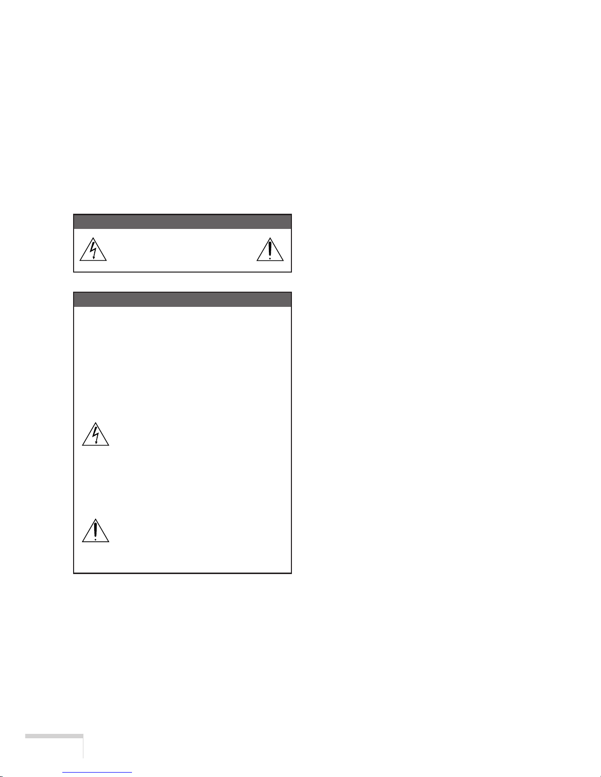
WARNING
TO PREVENT FIRE OR SHOCK HAZARDS,
DO NOT EXPOSE THIS UNIT TO RAIN OR
MOISTURE. ALSO DO NOT USE THIS UNIT’S
POLARIZED PLUG WITH AN EXTENSION
CORD RECEPTACLE OR OTHER OUTLETS,
UNLESS THE PRONGS CAN BE FULLY INSERTED. REFRAIN FROM OPENING THE
CABINET AS THERE ARE HIGH-VOLTAGE
COMPONENTS INSIDE. REFER SERVICING
TO QUALIFIED SERVICE PERSONNEL.
CAUTION
RISK OF ELECTRIC SHOCK
DO NOT OPEN
CAUTION
TO REDUCE THE RISK OF ELECTRIC
SHOCK, DO NOT OPEN COVER. NO
USER-SERVICEABLE PARTS INSIDE.
REFER SERVICING TO QUALIFIED SERVICE PERSONNEL.
This symbol warns the user that
uninsulated voltage within the unit
may have sufficient magnitude to
cause electric shock. Therefore, it
is dangerous to make any kind of
contact with any part inside of this
unit.
This symbol alerts the user that important literature concerning the
operation and maintenance of this
unit has been included. Therefore,
it should be read carefully in order
to avoid any problems.
DOC compliance Notice
This Class A digital apparatus meets all requirements of the Canadian Interference-Causing
Equipment Regulations.
Precautions: Please read this manual carefully
before using your iS8-2K and keep the manual
handy for future reference.
WARNING
This is a Class A product. In a domestic environment this product may cause radio interference in which case the user may be required to
take adequate measures.
CAUTION
• In order to reduce any interference with radio and television reception use a signal
cable with ferrite core attached.
Use of signal cables without a ferrite core
attached may cause interference with radio and television reception.
• This equipment has been tested and found
to comply with the limits for a Class A digital device, pursuant to Part 15 of the FCC
Rules. These limits are designed to provide
reasonable protection against harmful interference when the equipment is operated in
a commercial environment. This equipment
generates, uses, and can radiate radio frequency energy and, if not installed and used
in accordance with the installation manual,
may cause harmful interference to radio
communications.
Operation of this equipment in a residential
area is likely to cause harmful interference
in which case the user will be required to
correct the interference at his own expe
E-i
Page 3

Important Safeguards
These safety instructions are to ensure the long
life of your projector and to prevent fire and
shock. Please read them carefully and heed all
warnings.
Installation
1. Place the projector on a flat, level surface
and in a dry area free from dust and moisture.
2. Do not place the projector in direct sunlight,
near heaters or heat radiating appliances.
3. Exposure to direct sunlight, smoke or steam
could harm internal components.
4. Handle your projector carefully. Dropping or
jarring your projector could damage internal components.
5. To carry the projector, a minimum of four
persons are required.
Do not hold the lens part and the three anamorphic lens shafts with your hand. Otherwise the projector may tumble or drop,
causing personal injury.
6. Do not place heavy objects on top of the
projector.
7. If you wish to have the projector installed
on the ceiling:
a Do not attempt to install the projector
yourself.
b The projector must be installed by quali-
fied technicians in order to ensure proper
operation and reduce the risk of bodily
injury.
c In addition, the ceiling must be strong
enough to support the projector and the
installation must be in accordance with
any local building codes.
d Please consult your dealer for more in-
formation.
e Do not attempt to stack projectors on the
ceiling.
Power Supply
1. The projector is designed to operate on a
power supply of 2.8 KW AC200-240V 50/
60Hz. Ensure that your power supply fits
this requirement before attempting to use
your projector.
2. Consult your dealer for installing the power
cord to the projector. DO NOT install the
power cord by yourself. Doing so may cause
a fire or electric shock.
3. Handle the power cord carefully and avoid
excessive bending. Do not place any heavy
objects on the power cord. A damaged cord
can cause electric shock or fire.
4. If the projector will not be used for an extended period of time, disconnect the plug
from the power outlet.
5. Placing the power cord and the signal cable
closely to each other can cause beat noise.
If this happens, keep the two separated so
that beat noise is not generated.
Beat nise is corruption of the picture often
seen as a rolling band moving through the
image.
6. Do not touch the power plug during a thunderstorm. Doing so can cause elecrical
shock or fire.
Cleaning
1. Unplug the projector before cleaning.
2. Clean the cabinet periodically with a damp
cloth. If heavily soiled, use a mild detergent.
Never use strong detergents or solvents
such as alcohol or thinner.
3. Use a blower or lens paper to clean the lens,
and be careful not to scratch or mar the lens.
E-ii
Page 4

Fire and Shock Precautions
1. Ensure that there is sufficient ventilation and
that vents are unobstructed to prevent potentially dangerous concentrations of ozone
and the build-up of heat inside your projector. Allow at least 8 inches (20cm) of space
between your projector and a wall. Allow at
least 20 inches (50 cm) of space between
the ventilation outlet and object.
2. Prevent foreign objects such as paper clips
and bits of paper from falling into your projector. Do not attempt to retrieve any objects that might fall into your projector. Do
not insert any metal objects such as a wire
or screwdriver into your projector. If something should fall into your projector, disconnect it immediately and have the object removed by a qualified service person.
3. Do not place any liquids on top of your projector. Refer servicing to qualified service
personnel if liquid has been spilled.
4. Keep any items such as magnifying glass
out of the light path of the projector. The
light being projected from the lens is extensive, therefore any kind of abnormal objects
that can redirect light coming out of the lens,
can cause unpredictable outcome such as
fire or injury to the eyes.
5. Do not cover the lens with the supplied lens
cap or equivalent while the projector is on.
Doing so can lead to melting of the cap and
possibly burning your hands due to the heat
emitted from the light output.
CAUTION: High Pressure Lamp May Explode
if Improperly Handled. Refer Servicing to Qualified Service Personnel.
Lamp Caution: Please read before
operation
Due to the lamp being sealed in a pressurized
environment, there is a small risk of explosion,
if not operated correctly. There is minimal risk
involved, if the unit is in proper working order,
but if damaged or operated beyond the recommended 750 hours, the risk of explosion increases.
Please note that there is a warning system built
in, that displays following message when you
reach 750 hours (shortest life) of operation
“Lamp Warning”. When you see this message
please contact your dealer for a replacement. If
the lamp does explode, smoke will be discharged from the vents located on the back of
the unit. This smoke is comprised of glass in
particulate form and Xenon gas, and will not
cause harm if kept out of your eyes. If your eyes
have been exposed to this gas, please flush your
eyes out with water immediately and seek immediate medical attention. Do not rub your eyes!
This could cause serious injury.
WARNING: Do not look into the lens while the
projector is on. Serious damage to your eyes
could result.
CAUTION
Do not unplug the power cable from the wall
outlet under any one of the following circumstances. Doing so can cause damage to the
projector:
• Immediately after the cooling fan(s) stops
working (After the projector is turned off with
the POWER OFF button the cooling fan(s)
continues to work for 3 minutes while the
POWER indicator is blinking Orange).
E-iii
Page 5
Précaution: lire attentivement ce manuel avant
d’utiliser le iS8-2K et le conserver à portée de
main pour future référence.
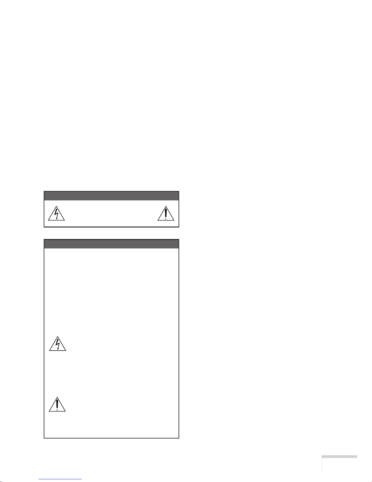
AVERTISSEMENT
POUR EVITER UN INCENDIE OU UN RISQUE
D’ELECTROCUTION NE PAS EXPOSER CET
ENSEMBLE A LA PLUIE OU A L’HUMIDITE;
DE MEME, NE PAS BRANCHER LA PRISE
POLAIRE AVEC UNE RALLONGE A MOINS
QUE LES BROCHES DE LA PREMIERE NE
S’Y INSERENT PLEINEMENT.
EVITER D’OUVRIR LE COFFRET CAR IL Y A,
A L’INTERIEUR DES COMPOSANTS SOUMIS
A UNE HAUTE-TENSION; POUR LES REPARATIONS, S’ADRESSER A UN PERSONNEL
QUALIFIE.
ATTENTION
RISQUE D’ELECTROCUTION
NE PAS OUVRIR
ATTENTION
POUR EVITER LES RISQUES
D’ELECTROCUTION, NE PAS OUVRIR LE
COUVERCLE. AUCUN DES ELEMENTS
INTERNES NE DOIT ETRE REPARE PAR
L’UTILISATEUR. NE CONFIER
L’ENTRETIEN QU’A UN PERSONNEL
QUALIFIE.
L’éclair fléché dans un triangle
équilatéral est destiné à avertir
l’utilisateur de la présence, dans
l’appareil, d’une zone non-isolée
soumise à une haute-tension dont
l’intensité èst suffisante pour
constituer un risque d’électrocution.
Le point d’exclamation dans un triangle équilatéral est destiné à attirer
l’attention de l’utilisateur sur la
présence d’informations de
fonctionnement et d’entretien
importantes dans la brochure
accompagnant l’appareil.
DOC avis de conformité
Cet appareil numérique de la classe A respecte
toutes les exigences du Réglement sur le
Matériel D’interférence du Canada.
Recommandations importantes
Ces instructions de sécurité ont pour but
d’assurer une longue vie à votre projecteur et
d’éviter un incendie ou une décharge électrique.
Prière de les lire attentivement et de tenir
compte de tous les avertissements.
Installation
1. Placer le projecteur sur une surface plane
et de niveau, et dans un endroit sec et à
l’abri des poussières et de l’humidité.
2. Ne pas exposer le projecteur aux rayons
directs du soleil, ni le placer près d’un
chauffage ou de dispositifs de radiation de
chaleur.
3. L’exposition aux rayons directs du soleil, à
la fumée ou à la vapeur pourrait
endommager des composants internes.
4. Manipuler le projecteur avec précaution. La
chute du le projecteur ou lui donner des
chocs pourrait endommager des
composants internes.
5. Le transport du projecteur doit être effectué
par quatre personnes au minimum.
Ne pas saisir le projecteur par son objectif
ni par les trois des anamorphoseurs. Le cas
échéant, le projecteur risque de se
renverser ou de tomber et d’être à l’origine
d’un accident corporel.
6. Ne pas poser d’objets lourds sur le dessus
du projecteur.
7. Si vous voulez installer le projecteur au
plafond:
a. N’essayez pas d’installer le projecteur
vous-même.
F-i
Page 6

b. Le projecteur doit être installé par un
technicien qualifié pour garantir une installation réussie et réduire le risque
d’éventuelles blessures corporelles.
c. De plus le plafond doit être suffisamment
solide pour supporter le projecteur et
l’installation doit être conforme aux
réglementations locales de construction.
d. Veuillez consulter votre revendeur pour
de plus amples informations.
e. Ne pas superposer les projecteurs
accrochés au plafond.
Alimentation
1. Le projecteur est conçu pour fonctionner
sous une tension d’alimentation de 2,8 KW
CA 200-240 V 50/60 Hz. S’assurer que la
tension du secteur soit conforme à ces
caractéristiques avant d’utiliser le
projecteur.
2. Pour l’installation du cordon d’alimentation
électrique sur le projecteur, voir le
concessionnaire. NE PAS intaller le cordon
d’alimentation électrique soi-même. Il y a
risque d’incendie ou d’électrocution.
3. Manipuler le cordon d’alimentation avec
précaution et éviter des flexions excessives.
Ne placez pas d’objets lourds sur le cordon
d’alimentation. Un cordon endommagé peut
occasionner une décharge électrique ou un
incendie.
4. Si le projecteur n’est pas utilisé pendant une
longue période, débrancher la fiche de la
prise de courant.
5. Placer le cordon d’alimentation et le câble
de signal tout prés l’un de l’autre peut
occasionner un bruit de battement. Si cela
se produit, les maintenir séparés jusqu’à ce
que le bruit de battement disparaisse.
6. Ne pas toucher la prise d’alimentation en
courant pendant un orage. Cela pourrait
causer un choc électrique.
Nettoyage
1. Débrancher le projecteur avant de le
nettoyer.
2. Nettoyer régulièrement le boîtier extérieur
avec un chiffon humide. S’il est trés sale,
utiliser un détergent doux. Ne jamais utiliser
de détergent forts ou de solvants tels que
de l’alcool ou du diluant.
3. Utiliser un souffleur ou du papier pour objectif
pour nettoyer l’objectif, et veiller à ne pas
rayer ou endommager l’objectif.
Précautions contre l’incendie ou
la décharge
1. S’assurer qu’il y ait une ventilation suffisante
et que les ouvertures ne soient pas
obstruées afin d’éviter des concentrations
potentiellement dangereuses d’ozone et
l’accumulation de chaleur à l’intérieur du
projecteur. Laisser au moins 20 cm
d’espace entre le projecteur et un mur.
Veuillez laisser un espace libre d’au moins
50 cm (20 pouces) entre les orifices de ventilation et l’objet.
2. Empêcher tous cocps étrangers tels que
des attaches trombones ou des morceaux
de papier de tomber à l’intérieur du
projecteur. Ne pas essayer de récuperer
des objets qui seraient tombés dans le
projecteur. Ne pas introduire d’objets
métalliques tels que fil ou un tournevis dans
le projecteur. En cas de chute d’objet dans
le projecteur, le débrancher immédiatement
et faire enlever l’objet par un technicien
agréé.
3. Ne pas poser de liquides sur le dessus du
projecteur. Confier la réparation à du personnel technique qualifié si du liquide a été
renversé.
4. Maintenez tout ce qui s’apparente à une
loupe en dehors du faisceau lumineux du
projecteur. La lumière projetée par l’objectif
est très puissante, de sorte que tout objet
F-ii
Page 7

en opposition pourrait dévier le faisceau
provenant de l’objectif, ce qui pourrait avoir
des conséquences imprévues telles qu’un
incendie ou une lésion occulaire.
5. Ne bouchez pas l’objectif avec son
couvercle fourni lorsque le projecteur est
allumé. Faire cela pourrait faire fondre le
couvercle et peut-être brûler vos mains à
cause de la châleur émise par le faisceau
lumineux.
ATTENTION: La lampe à haute pression peut
exploser si elle est manipulée incorrectement.
Confier l’entretien à du personnel d’entretien
qualifié.
Précautions avec la lampe : lire
avant l’utilisation
La lampe a été scellée dans un environnement
sous pression, et il y a donc un petit risque
d’explosion, si elle n’est pas utilisée
correctement. Le risque est minime si l’appareil
est en bon ordre de marche, mais s’il est
endommagé ou utilisé au-delà des 750 heures
recommandées, le risque d’explosion augmente
alors.
Il est à noter l’existence d’un systéme
d’avertissement intégré, lequel affiche le message “Lamp Warning” lorsque les 750 heures
(la vie la plus courte) de fonctionnement sont
atteintes. Lorsque ce message apparaît, priére
de contacter votre revendeur pour un
remplacement.
Si la lampe explose, de la fumée peut étre
produite par les fentes d’aération situées sur
l’arrière de l’appareil. Cette fumée est
composée de verre sous forme de particules et
de gaz de Xenon, et n’est pas nuisible si elle
est maintenue à distance des yeux. Si les yeux
sont exposés a ce gaz, les rincer
immédiatement à l’eau courante et con sulter
tout de suite un médecin. Ne pas se frotter les
yeux ! Cela pourrait provoquer une grave
blessure.
AVERTISSEMENT:
Ne pas regarder dans l’objectif lorsque le
projecteur est allumé. De sérieux dommages
aux yeux pourraient en résulter.
ATTENTION
Ne pas debrancher le câble d’alimentation de
la prise du secteur dans les circonstances
suivantes car cela risque d’endommager le
projecteur:
• Immediatement après que le(s)
ventilateur(s) de refroidissement se
met(tent) à l’arrêt (quand le projecteur est
mis à l’arrêt à l’aide du bouton POWER OFF,
le(s) ventilateur(s) de refroidissement
continuent de tourner pendant encore 3
minutes tandis que le témoin POWER
clignote en orange).
F-iii
Page 8
3. GSGV Bestimmungen bzgl. der
Geräuschabgabe
Der Schalldruckpegel entsprechend den
Normen ISO 3744 oder ISO 7779 betragt
weniger als 70 dB (A).
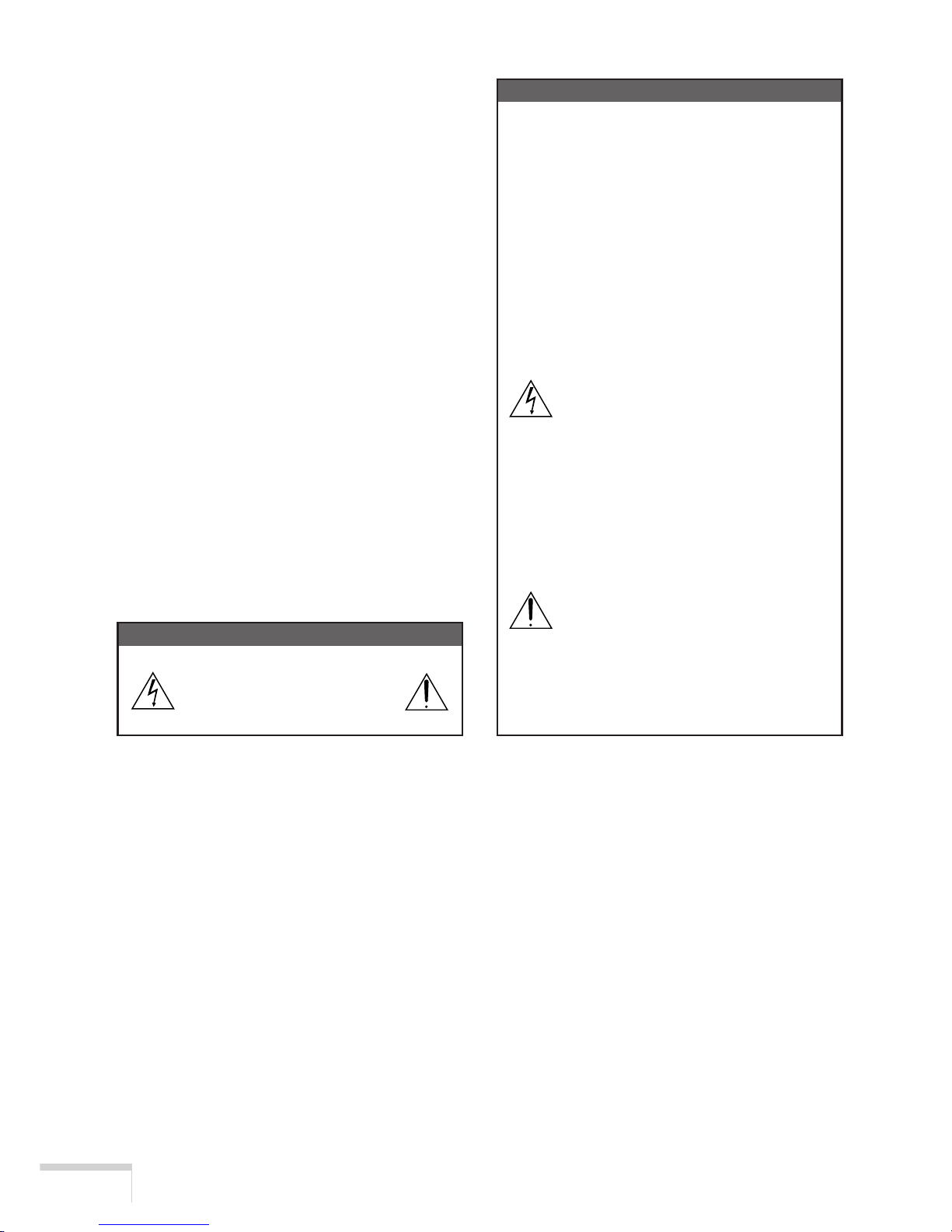
WARNUNG
ZUR VERMEIDUNG VON FEUER UND ELEKTRISCHEN SCHLÄGEN DARF DAS GERÄT
WEDER REGEN NOCH FEUCHTIGKEIT AUSGESETZT WERDEN. DER POLARISIERTE
STECKER DIESES GERÄTES DARF NUR
DANN IN EIN VERLÄNGERUNGSKABEL
ODER IN EINE STECKDOSE EINGESTECKT
WERDEN, WENN DIE STECKKONTAKTE
VOLLSTÄNDIG EINGESTECKT WERDEN
KONNEN. UNTERLASSEN SIE, DAS GERÄT
ZU OFFNEN, DA DADURCH IM GERÄT
FREILIEGENDE HOCHSPANNUNGSFÜHRENDE TEILE BERÜHRT WERDEN
KÖNNEN. LASSEN SIE DEN KUNDENDIENST NUR VON HIERFÜR QUALIFIZIERTEN
PERSONEN DURCHFÜHREN.
ACHTUNG
GEFAHR DURCH ELEKTRISCHEN
SCHLAG
NICHT ÖFFNEN
ACHTUNG
ZUR VERMEIDUNG EINES ELEKTRISCHEN SCHLAGES ÖFFNEN SIE
NICHT DAS GEHÄUSE. INNERHALB DES
GEHÄUSES BEFINDEN SICH KEINE FÜR
DIE BEDIENUNG DES GERÄTES ERFORDERLICHEN TEILE. LASSEN SIE DEN
KUNDENDIENST NUR VON HIERFÜR
QUALIFIZIERTEN PERSONEN DURCHFÜHREN.
DIESES SYMBOL WARNT DEN
BEDIENER, DASS INNERHALB
DES GERÄTES UNISOLIERTE
TEILE VORHANDEN SIND, DIE
HOCHSPANNUNG FÜHREN UND
DEREN BERÜHRUNG EINEN
ELEKTRISCHEN SCHLAG
VERURSACHEN KANN.
DIESES SYMBOL MACHT DEN
BËDIENER DARAUF AUFMERKSAM, DASS WICHTIGE, DEN
BETRIEB UND
DIE WARTUNG DES GERÄTES
BETREFFENDE SCHRIFTEN
BEIGEFÜGT SIND. UM IRGENDWELCHE PROBLEME ZU
VERMEIDEN, SOLLTEN DIESE
BESCHREIBUNGEN SORGFÄLTIG GELESEN WERDEN.
Vorsichtsmaßnahmen: Lesen Sie sich dieses
Handbuch bitte sorgfaltig durch, bevor Sie den
iS8-2K benutzen, und bewahren Sie das
Bedienungshandbuch in greifbarer Nahe als
spatere Referenz auf.
Wichtige Sicherheitshinweise
Diese Sicherheitshinweise sollen eine lange
Lebensdauer Ihres Projektors sicherstellen und
vor Feuer und elektrischen Schlägen schützen.
Lesen Sie diese Hinweise sorgfältig durch und
beachten Sie alle Warnungen.
G-i
Page 9

Installation
1. Stellen Sie den Projektor auf eine flache,
waagerechte Fläche in einer trockenen
Umgebung; frei von Staub und Feuchtigkeit.
2. Stellen Sie den Projektor weder in direktes
Sonnenlicht noch in die Nähe einer Heizung
oder sonstiger Hitze abstrahlender
Einrichtungen.
3. Wenn das Gerät direktem Sonnenlicht, Rauch
oder Dampf ausgesetzt wird, können interne
Komponenten beschadigt werden.
4. Behandeln Sie Ihren Projektor vorsichtig.
Fallenlassen oder starkes Schutteln kann
interne Komponenten beschädigen.
5. Zum Tragen des Projektors werden mindestens vier Personen benötigt.
Den Projektor nicht am Linsenbereich oder
den drei anamorphotischen Linsenwellen
tragen. Beschädigungs- und Verletzungsgefahr.
6. Legen Sie keine schweren Gegenstände
auf den Projektor.
7. Wenn der Projektor an der Decke installiert
werden soll:
aVersuchen Sie nicht, den Projektor
selbst zu installieren.
b Der Projektor muss von qualifizierten
Technikern installiert werden, um einen
ordnungsgemäßen Betrieb sicherzustellen und die Verletzungsgefahr zu
reduzieren.
c Die Decke muss für das Gewicht des
Projektors ausreichende Festigkeit aufweisen, und die Installation muss
entsprechend den örtlichen Bauvorschriften ausgeführt werden.
dWeitere Informationen erhalten Sie von
Ihrem Fachhändler.
eVersuchen Sie nicht, mehrere Projek-
toren an der Decke übereinander zu
stapeln.
Spannungsversorgung
1. Der Projektor wurde für eine Netzspannung
von 2,8KW 200-240 V Wechselstrom/50/60
Hz konzipiert. Stellen Sie sicher, dass die
vorhandene Spannungsversorgung diesen
Vorgaben entspricht, bevor Sie versuchen,
Ihren Projektor zu betreiben.
2. Zum Installieren des Netzkabels am Projektor wenden Sie sich bitte an Ihren Fachhändler. UNTER KEINEN UMSTÄNDEN
versuchen, das Netzkabel selbst zu installieren. Brand- und Schlaggefahr.
3. Behandeln Sie das Netzkabel vorsichtig und
vermeiden Sie Knicke. Legen Sie keine
schweren Gegenständde das Netzkabel.
Ein beschädigtes Netzkabel kann elektrische Schläge oder einen Brand verursachen.
4. Wenn der Projektor über eine längere Zeit
nicht benutzt wird, ziehen Sie den Stecker
aus der Netzsteckdose.
5. Wenn Sie das Netzkabel und das Signalkabel in unmittelbarer Nähe zueinander
platzieren, kann Überlagerungsrauschen
auftreten. Vergrößern Sie in einem derartigen Fall den Abstand zwischen diesen
beiden Kabeln.
6. Berühren Sie während eines Gewitters den
Netzstecker auf keinen Fall. Wenn Sie dies
nicht beachten, kann dies zu einem
elektrischen Schlag führen.
Reinigung
1. Trennen Sie den Projektor vor der
Reinigung von der Netzsteckdose ab.
2. Reinigen Sie das Gehäuse regelmäßig mit
einem feuchten Tuch. Bei starker Verschmutzung verwenden Sie ein mildes
Reinigungsmittel. Reinigen Sie das Gerät
niemals mit starken Reinigungsoder Lösungs-mitteln wie z.B. Alkohol oder Verdünner.
3. Reinigen Sie die Linse mit einer Blaseinrichtung oder einem Linsentuch. Beachten
Sie dabei, dass die Linsenoberfläche weder zerkratzt noch auf andere Weise beschädigt wird.
G-ii
Page 10

Vorsichtsmasnahmen zur Vermeidung von Bränden und elektrischen Schlägen
1. Sorgen Sie für ausreichende Belüuftung
und stellen Sie außerdem sicher, dass die
Lüftungsschlitze frei bleiben, damit sich
innerhalb des Projektors kein Hitzestau
bilden kann. Lassen Sie mindestens 20 cm
Abstand zwischen Ihrem Projektor und der
Wand. Der Abstand zwischen den Belüftung
und anderen Gegenständen sollte
mindestens 50 cm betragen.
2. Vermeiden Sie, dass Fremdgegenstande
wie Büroklammern und Papierschnipsel in
den Projektor fallen. Versuchen Sie nicht,
in den Projektor gefallene Gegenstände
selbst zu entfernen. Stecken Sie keine Metallgegenstände wie einen Draht oder
Schraubendreher in Ihren Projektor. Wenn
etwas in den Projektor gefallen ist, müssen
Sie sofort den Netzstecker ziehen und den
Gegenstand von qualifiziertem Servicepersonal entfernen lassen.
3. Stellen Sie keine mit Flüssigkeit gefüllten
Gefäße auf Ihren Projektor. Überlassen Sie
die Reparatur ausschließlich qualifiziertem
Servicepersonal, wenn Flüssigkeit verschüttet worden ist.
4. Lichtkegel des Projektors fern. Da das von
der Linse projizierte Licht umfassend ist,
können alle abnormalen Gegenstände, die
in der Lage sind, das aus der Linse austretende Licht umzulenken, unvorhersehbare
Ereignisse wie z.B. einen Brand oder Augenverletzungen verursachen.
5. Bedecken Sie die Linse nicht mit der
mitgelieferten Linsenkape o.ä. wärend der
Projektor eingeschaltet ist. Dies kann ein
Schmelzen der Kappe verursachen.
Darüber hinaus würden Sie sich aufgrund
der vom Lichtausgang abgestrahlten Hitze
wahrscheinlich die Hände verbrennen.
VORSICHT: Bei unsachgemäßer Handhabung
kann die Hochdrucklampe explodieren.
Überlassen Sie die Reparatur ausschließlich
qualifiziertem Servicepersonal.
Vorsichtsmaßnahmen bezüglich
der Lampe: Bitte vor dem Betrieb
durchlesen
Aufgrund der unter Druck luftdicht verschlossenen Lampe besteht bei falscher Handhabung
eine geringe Explosionsgefahr. Wenn sich das
Gerät in einwandfreiem Zustand befindet, ist
dieses Risiko minimal; es erhöht sich jedoch
im Falle einer Beschädigung oder bei einer
Benutzung über die empfohlenen 750 Betriebsstunden hinaus. Beachten Sie bitte, dass im
Gerät ein Warnsystem integriert ist, das bei
Erreichen der 750 Betriebsstunden (kürzestes
Leben) die nachfolgende Meldung anzeigt:
“Lamp Warning”. Beauftragen Sie Ihren Händer,
sofern diese Meldung auf dem Display erscheint.
Im Falle einer Lampenexplosion tritt aus den
Lüftungsschlitzen der Rückseite des Gerätes
Rauch aus. Dieser Rauch besteht aus einer
ganz besonderen Form von Glas und aus Xenon-Gas. Solange dieser Rauch nicht in die
Augen gelangt, bestehen keinerlei gesundheitliche Risiken.
Wenn Ihre Augen dem Gas ausgesetzt worden
sind, spülen Sie die Augen bitte sofort mit Wasser aus und konsultieren Sie einen Arzt. Reiben
Sie die Augen nicht!
Dies könnte ernsthafte Verletzungen zur Folge
haben.
WARNUNG: Schauen Sie nicht in die Linse,
wenn der Projektor eingeschaltet ist. Dies
könnte schwere Augenverletzungen zur Folge
haben.
VORSICHT
Unter den nachfolgend aufgeführten Umständen darf das Netzkabel nicht von der
Netzsteckdose abgetrennt werden, da dies
Beschädigungen des Projektors verursachen
könnte:
• Unmittelbar nach Stoppen des/der Ventilators/en (Nach dem Ausschalten des Projektors mit der POWER OFF-Taste bleibt/
bleiben der/die Ventilator/en weiterhin ca.
3 Minuten lang aktiv während die POWERAnzeige orangerot blinkt.)
G-iii
Page 11
J-i
J-i
本機を安全に正しく使用していただくため、ご使用の前に、この取扱説明書
生じたときにお読みください。
絵表示について
他の人々への危害や財産への損害を未然に防止するために、いろいろな絵表示をしていま
記号は注意(警告を含む)をうながすことを表しています。
記号はしてはいけないことを表しています。
絵
表
示
例
Page 12
J-ii
設置および輸送について
電源コードの取り付けについて
表示以外の電圧で使用しない
表示された電源電圧
AC100V〜120V,AC200V
電源コードの取り扱いは大切に
・
・
・ コードを加熱しない
販
故障したときは電源プラグを抜く
・
合は、本体の電源を切り、電源プラグをコンセン
水場や水にぬれるような所には置かない
使用しないでください。またプロジェクタの上に
水の入った容器を置かないでください。火災・感
風呂やシャワー室で使用しない
万一プロジェクタの内部に水などが入った場合
次のような所では使用しない
感電の原因となります。
水ぬれ禁止
Page 13
J-iii
内部に物を入れない
万一異物がプロジェクタ内部に入った場合は、ま
キャビネットは絶対にあけない
ランプカバーは外さない
破裂のおそれがありますので、サービスマン以外
分解禁止
雷が鳴りだしたら、電源プラグに触れない
プロジェクタのレンズをのぞかない
Page 14
J-iv
機器のアースは確実にとってください
本機の電源プラグはアースつき3芯プラグです。
機器の安全確保のため、機器のアースは確実に
ぬれた手で電源プラグに触れない
通風孔をふさがない
動作中にレンズキャップをしない
移動するときは電源コードを抜く
移動させる場合は、電源を切り必ず電源プラグを
移動するときはキャリングハンドルを持つ
必ずキャリングハンドルを持ってください。レン
長期間使用しないときは、電源プラグを抜く
お手入れの際は電源コードを抜く
投写中は排気口に触らない
注意
Page 15

J-v
点検・工事について
年に一度くらいは内部の掃除を販売店などにご
相談ください。プロジェクタの内部にほこりがた
販売店などにご相談ください。
注意
Page 16

J-vi
性能確保のため、次の点にご留意ください。
振動や衝撃が加わる場所への設置は避けてくださ
加わって内部の部品がいたみ、故障の原因となリ
振動や衝撃の加わらない場所に設置してくださ
外光が入らないほど、ハイコントラストで美しい
持って運んでください。その際、レンズはプロ
本体廃棄の際は、お買い上げの販売店にお問い合
化などにより、大きな音をともなって破裂した
光源に使われているランプの使用時間が750時間
表示されます。このメッセージが表
換を依頼してください。
気を行ってください。ガスを吸い込んだり、目に
入ったりした場合には、こすったりせずに流水で
洗い流し、すみやかに医師にご相談ください。
修理については、必ず販売店に依頼し、お客様ご
機器が故障するおそれがあります。
分間回転し、その間、
Page 17

1
TABLE OF CONTENTS
IMPORTANT INFORMATION
Safety Cautions
TABLE OF CONTENTS
1. What’s in the Box? and the Names of the
Projector Parts......................................................................... 2
1-1. Features................................................................................................................................. 2
1-2. What’s in the Box? ............................................................................................................... 3
1-3. Names of the projector parts................................................................................................. 4
1-4. Names of the remote control parts...................................................................................... 11
2. Installation and Connection ................................................. 14
2-1. Steps of setting up and connecting ..................................................................................... 14
2-2. Connecting the image input terminals ................................................................................14
2-3. Connecting the various control terminals ...........................................................................15
2-4. Connecting the power cord .................................................................................................16
3. Projection of Images (Basic Operation)............................... 17
3-1. Steps of projecting images.................................................................................................. 17
3-2. Step 1: Turning your projector on ..................................................................................... 17
3-3. Step 2: Selecting the title of input signal ...........................................................................19
3-4. Step 3: Adjusting the position and size of projected screen ..............................................20
3-5. Step 4: Turning your projector off .....................................................................................21
4. Using Menus ......................................................................... 23
4-1. Basic operation with adjustment menus .............................................................................23
4-2. Table of adjustment menus .................................................................................................26
4-3. Source Select ...................................................................................................................... 29
4-4. Setup ...................................................................................................................................29
4-5. Information .........................................................................................................................32
5. Maintenance of Your Projector ............................................ 34
5-1. Cleaning the cabinet ........................................................................................................... 34
5-2. Cleaning the lens ................................................................................................................35
6. Appendix ................................................................................ 36
Error code list.............................................................................................................................. 36
Troubleshooting ..........................................................................................................................38
Operation using an HTTP browser ............................................................................................. 39
Outline drawing .......................................................................................................................... 41
Specifications ..............................................................................................................................42
Index ...........................................................................................................................................50
Page 18

2
Checking the Supplied Items and the Names of the Projector Parts
1. What’s in the Box? and the Names of the
Projector Parts
1-1. Features
䢇 Compact projector for dedicated use with DLP Cinema
TM
Small integrated projector and lamp unit.
A small size of almost half the volume of conventional DLP Cinema
TM
projectors is realized by the
monoblock structure of projector and lamp console.
䢇 Various setups possible thanks to a variety of optional lens units and the facility for inverted
installation
An optional lens unit may be selected according to the desired screen size or the projection distance.
The facility of inverted installation of the projector body realizes both upward projection from a
low position and downward projection from a high position.
䢇 Fine adjustments of the screen by the lens shift function and lens memory function
The lens shift function allows fine adjustment of projection on the screen. Also, the lens memory
function allows storage of the zoom position and lens shift position according to the size of each
picture.
䢇 Up-to-date functions of DLP Cinema
TM
available
This projector supports CineLink
TM
, CineCanvasTM, CinePalletteTM and CineBlackTM, which are
the new functions for security, subtitles, etc., developed by Texas Instruments Incorporated.
(1) CineLink
TM
: Security management
This function can support the encryption of local link between server and projector, adds a
“watermark” to enable the tracing of pirated films (illegal copying), and provides other functions.
(2) CineCanvas
TM
: Image management
This function enables insertion of subtitles and captions, correction of distortion, changing of
resolution, etc.
(3) CinePallette
TM
: Color management
This function allows extension of color range, correction of colors, etc.
(4) CineBlack
TM
: Contrast management
This function realizes a color tone scale from pitch black to pure white.
DLP
TM
(Digital Light ProcessingTM), DMDTM (Digital Micromirror DeviceTM), DLP CinemaTM,
CineLink
TM
, CineCanvasTM, CinePalletteTM and CineBlackTM are trademarks of Texas Instruments.
Page 19

3
Checking the Supplied Items and the Names of the Projector Parts
1-2. What’s in the Box?
Please check the items supplied in your package.
< > iS8-2K Projector
< > Remote Control with Remote cable (wired)
< > DVI-D signal cable
< > Ferrite clamp core for HDSDI signal cable
< > User’s Manual
< > CompactFlash Memory card (16MB) with Adapter
< > Anamorphic lens mount with two shafts
< > Foot(x4)
NOTE
• Should any of the items delivered to you in the package be missing or damaged, please contact your dealer/
distributor (from whom you have purchased your projector) immediately with the information.
Page 20
4
Checking the Supplied Items and the Names of the Projector Parts
1-3. Names of the projector parts
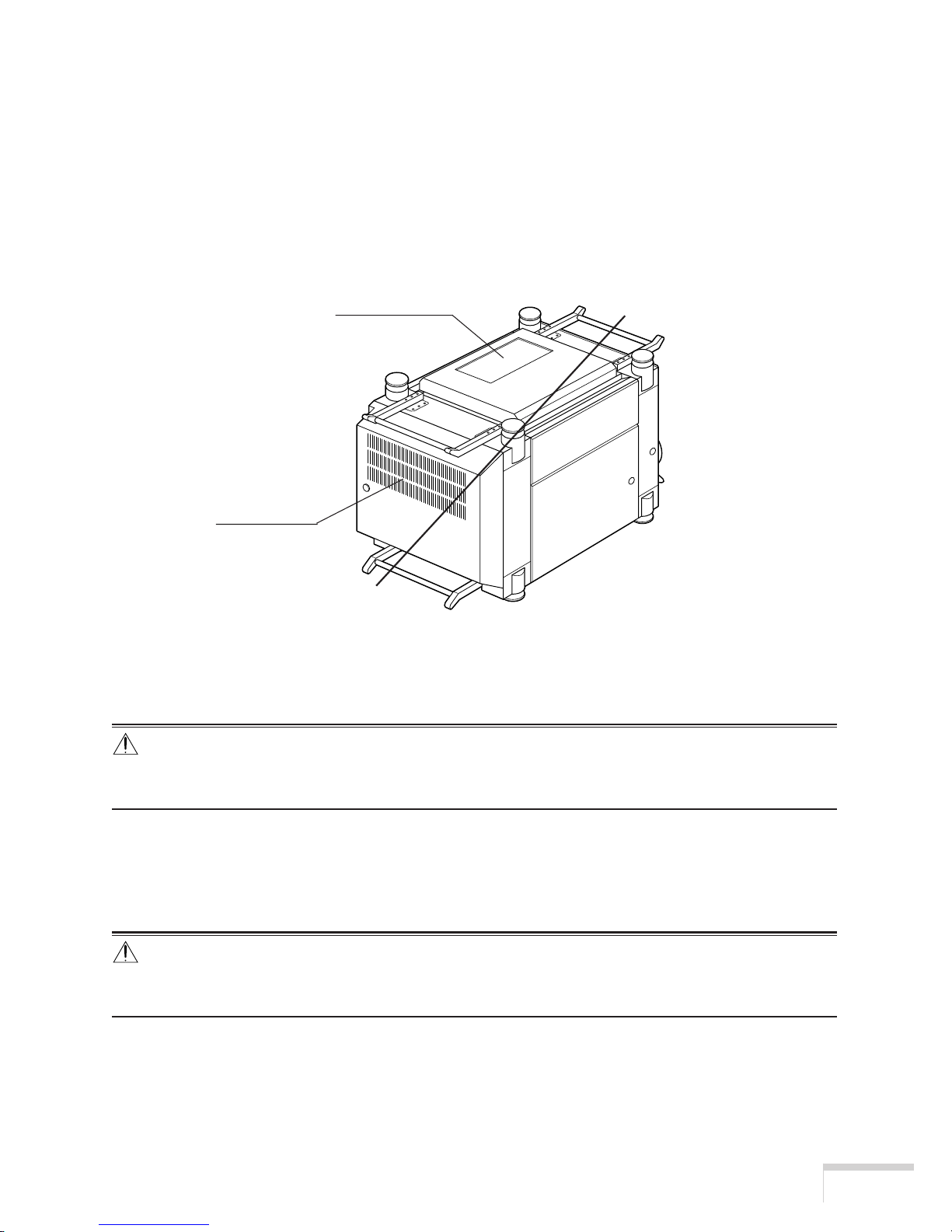
䡵 Front of the projector
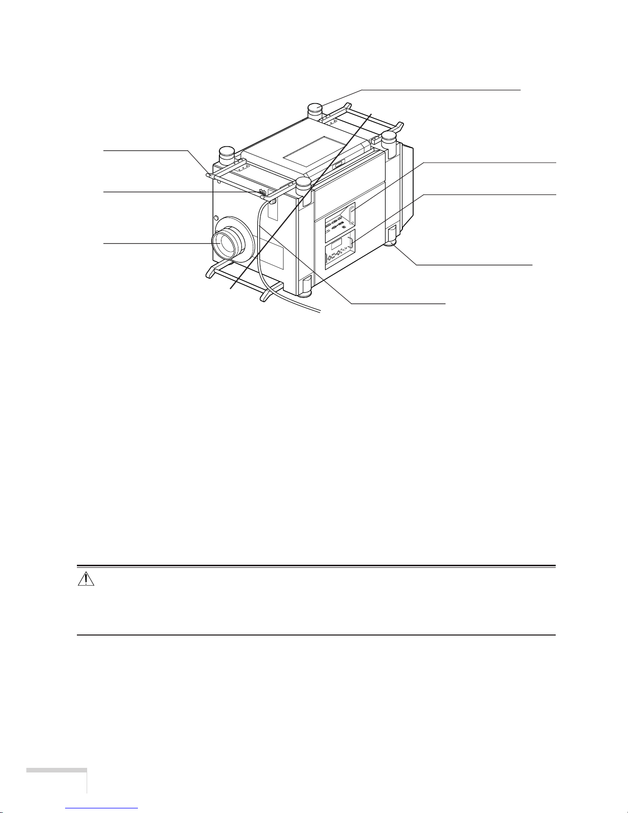
䢇 Feet ( in four positions on the bottom)
These feet are to be used in normal installation.
䢇 Power cord
Connect the power cord to an AC outlet.
䢇 Main power switch
Connect the power cord to an AC outlet and set the main power switch to ON, then your projector
will enter a standby state.
䢇 Carrying handles
Hold the carrying handles when carrying your projector.
There are a total of two carrying handles, a set of bottom ones on the front and the back of your
projector.
CAUTION
• Be sure to carry the projector using a minimum of four people.
When moving the projector, do not use any parts other than the carrying handles.
Otherwise the projector may tumble or drop, causing personal injury.
䢇 Lens (sold separately)
Images are projected from the lens.
Please contact your dealer/distributor to install or replace the lens.
Feet (in four position on the top)
Feet (in four position on
the bottom)
Main power switch
Power cord
Lens
Carrying handles
Connection terminal
Control panel
Page 21
5
Checking the Supplied Items and the Names of the Projector Parts
䢇 Control panel
On the control panel, power to your projector is turned on or off, signals are selected, and various
adjustments are made of projected screen. (See page 6)
䢇 Connection terminals
Various image signal cables are to be connected here. (See page 8)
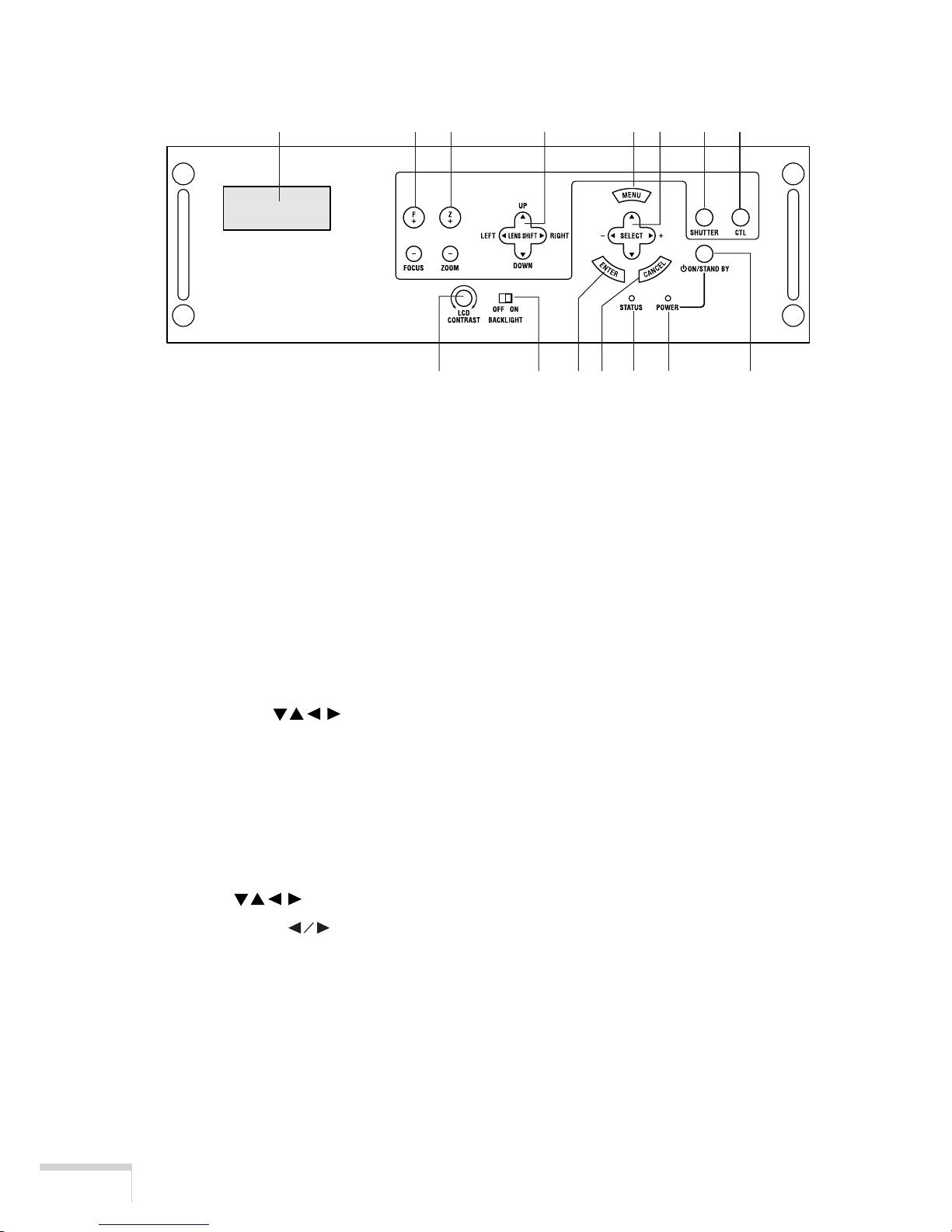
䡵 Rear of the projector
䢇 Air outlet
The heat of the lamp is vented here.
CAUTION
• Do not touch the air outlet when your projector is operating. Otherwise, the high temperature may cause
burns.
䢇 Air inlet
Air is taken in here to provide cooling of the projector.
CAUTION
• Do not cover the air inlet and outlet during operation. Inadequate air intake may lead to a rise in inside
temperature, thus causing a fire or serious projector failure.
Air outlet
Air inlet
Page 22
6
Checking the Supplied Items and the Names of the Projector Parts
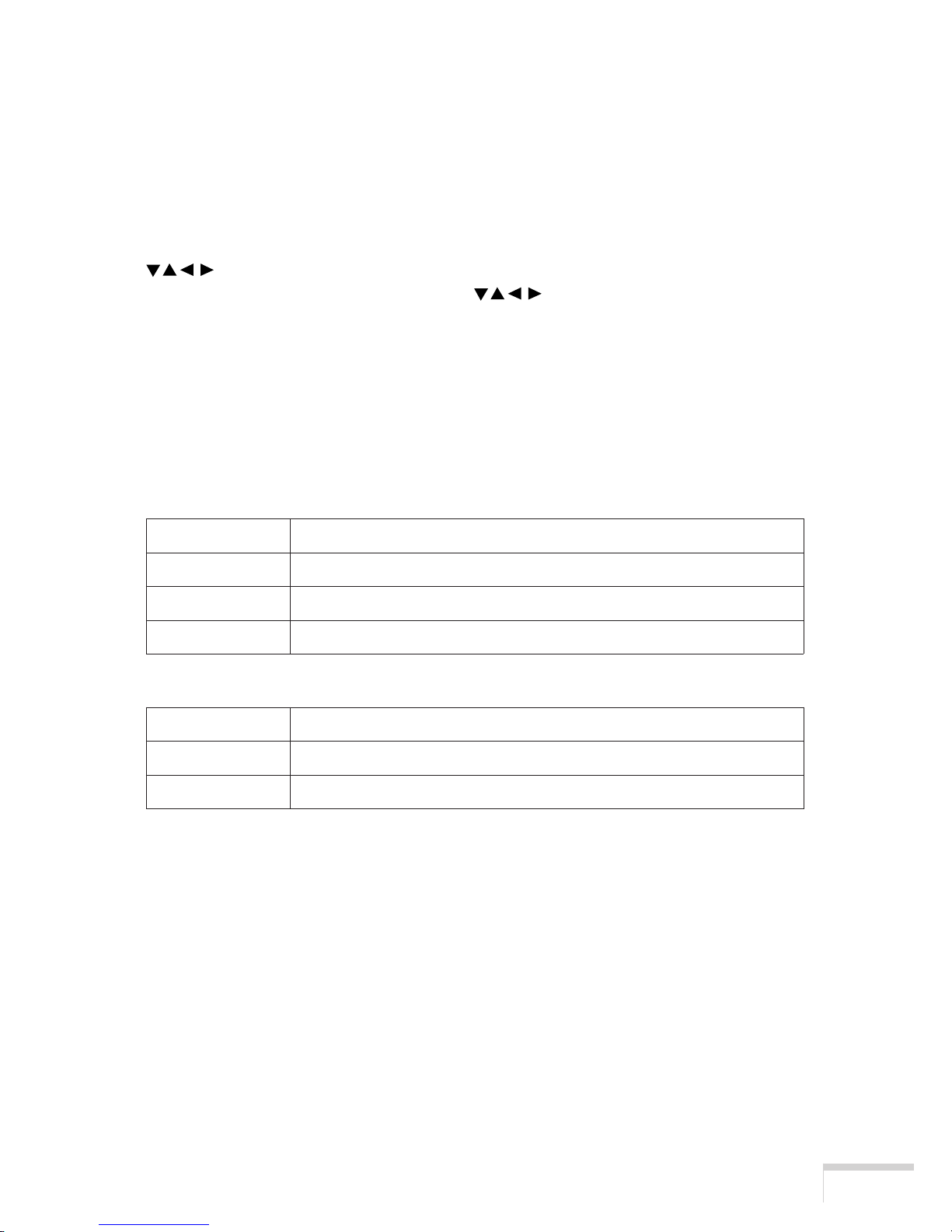
䡵 Control panel
1. LCD screen
The liquid crystal display screen shows menus and setting values for the adjustment of your projector.
2. FOCUS Ⳮ/ⴑ buttons
Press these buttons while depressing the CTL button, to bring the projected image into focus. (See
page 21)
3. ZOOM Ⳮ/ⴑ buttons
Press these buttons while depressing the CTL button, for fine adjustment of the size of projected
image. (See page 21)
4. LENS SHIFT
buttons
Press these buttons while depressing the CTL button, to move the projected image down, up, left or
right. (See page 20)
5. MENU button
Press this button, and menus for various settings and adjustments will be displayed. (See page 23)
6. SELECT
buttons
Press the SELECT button when a menu is displayed, and a menu item can be selected.
7. ENTER button
Press the ENTER button, and the displayed menu item is actioned.
8. CANCEL button
Press the CANCEL button to return to the previous menu item.
12
3456910
15
14 7 8 13 12 11
Page 23
7
Checking the Supplied Items and the Names of the Projector Parts
9. SHUTTER button
Press the SHUTTER button while depressing the CTL button, then the lens shutter will operate to
shut off the light for projection. Press this button again while depressing the CTL button to cancel
the operation of the lens shutter.
10. CTL button
Press the CTL button together with the FOCUS +/- button, ZOOM +/- button, LENS SHIFT
button and SHUTTER button.
The FOCUS +/-, ZOOM +/-, LENS SHIFT
and SHUTTER buttons do not function
when pressed alone.
11. POWER button
Press this button to turn on or off (standby) the power to your projector.
When turning on the power to the projector, first set the main power switch to ON, thereby setting
the projector in a standby state. (See page 17)
12. POWER indicator
13. STATUS indicator
14. BACKLIGHT switch
Operate this switch to turn on the back light of the LCD screen.
15. LCD CONTRAST Adjustment Dial
Use this dial to adjust the contrast of the LCD screen.
Green lighting When power is on.
Green blinking When the lens shutter is closed.
Orange lighting When power is off (in standby state).
Orange blinking When the cooling fan(s) is running immediately after power-off.
Off When the projector is operating normally.
Green lighting When power is off (in standby state).
Red blinking When an error has occurred. An error code is displayed on the LCD screen.
Page 24
8
Checking the Supplied Items and the Names of the Projector Parts
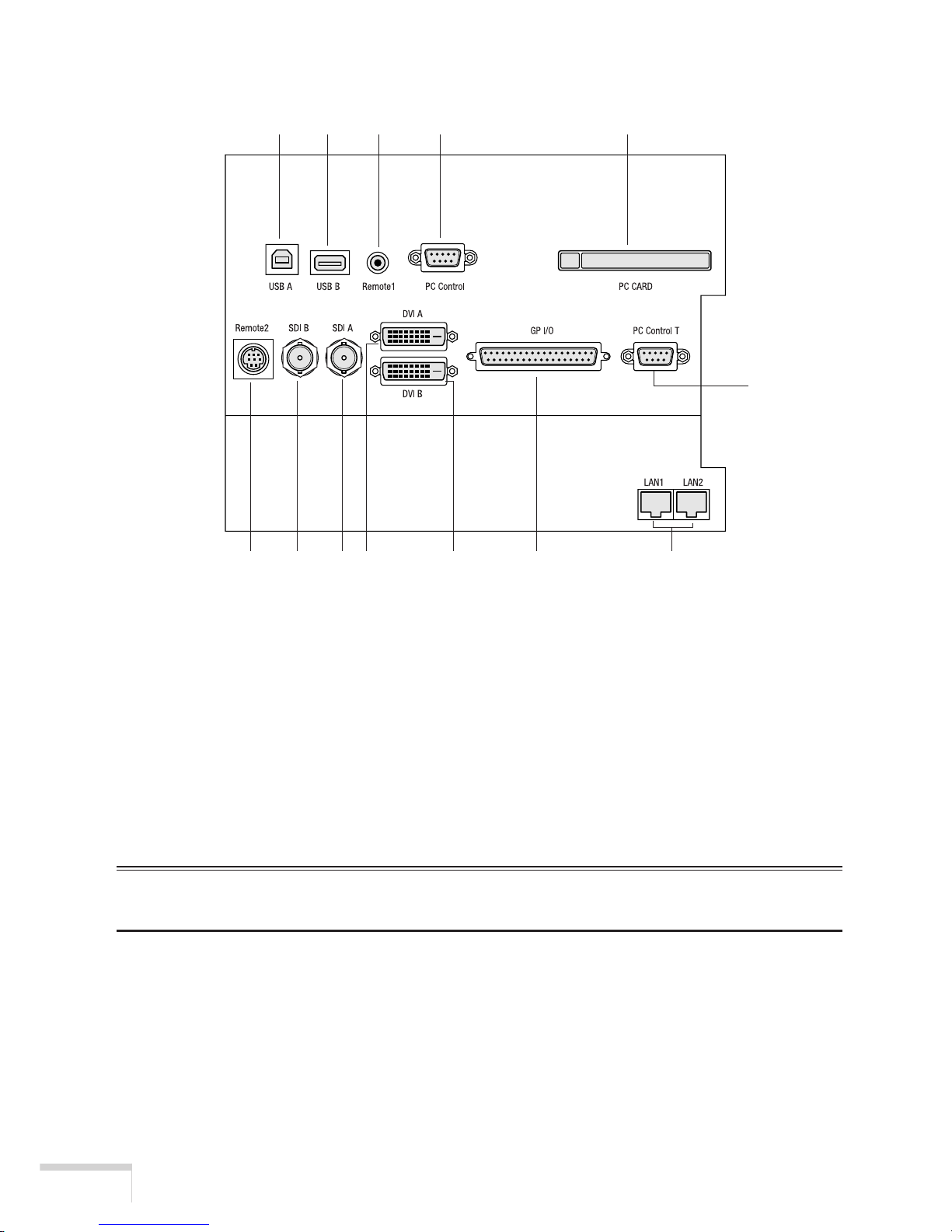
䡵 Connection terminals
1. USB port (Type A) (USB A)
This port is for future extension.
2. USB port (Type B) (USB B)
Use this port when controlling your projector in USB connection from a PC. Use a commercially
available USB cable to connect the projector to the PC.
3. Remote control terminal (REMOTE 1)
Connect the remote control of the projector, using the supplied remote control cable.
NOTE
• You cannot operate the remote control of your projector unless it is connected by the remote control cable.
4. PC control terminal (PC CONTROL) (Mini D-Sub 9P)
Use this terminal when controlling your projector in serial connection from a PC. Use a commercially
available RS-232C straight cable to connect the projector to the PC.
123 4 5
6789 10 11 13
12
Page 25
9
Checking the Supplied Items and the Names of the Projector Parts
5. PC card slot
• Use this slot when doing maintenance on your projector. Set a commercially available flash
memory card.
• Set a wireless LAN card, and you can control the projector from a PC, using a wireless LAN.
Please inquire your dealer/distributor about a wireless LAN card that can be used.
6. External control terminal (REMOTE 2) (Mini DIN 8P)
Use this terminal when controlling your projector from an external switcher.
NOTE
• When the GPIO control is in “Enable,” the LENS SHUTTER function will not work.
7. HDSDI B input terminal (SDI-B) (BNC)
Connect a Video Server or Video source to this terminal. Use a 75Ω coaxial cable.
8. HDSDI A input terminal (SDI-A) (BNC)
Connect a Video Server or Video source to this terminal. Use a 75Ω coaxial cable.
9. DVI-D A input terminal (DVI-A) (DVI-D 24P)
Connect the DVI-D output terminal of a PC to this terminal. Use a commercially available DVI-D
signal cable.
10. DVI-D B input terminal (DVI-B) (DVI-D 24P)
Connect the DVI-D output terminal of a PC to this terminal. Use a commercially available DVI-D
signal cable.
11. External control terminal (GP I/O) (D-Sub 25P)
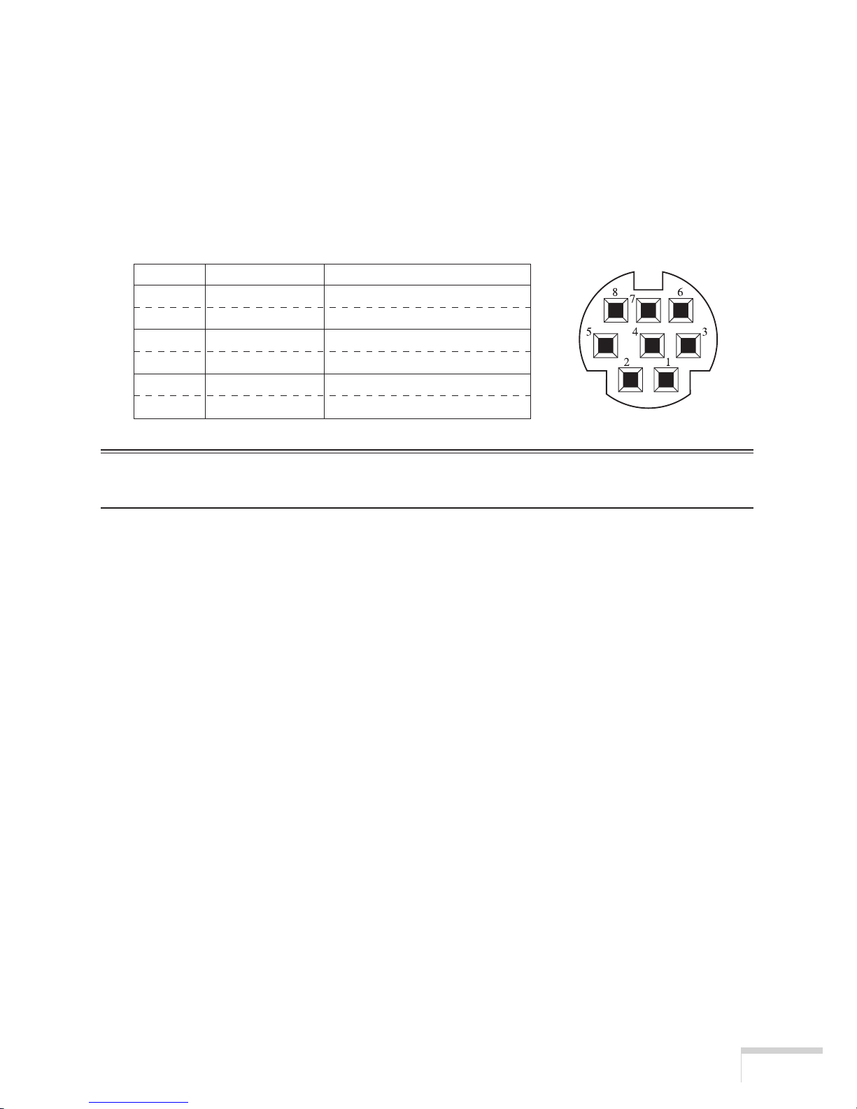
This terminal is for future extension.
Pin No. SHORT/OPEN FUNCTION
6-4 SHORT External control mode ON
6 OPEN External control mode OFF
3-4 SHORT POWER ON
3 OPEN POWER OFF
8-4 SHORT LENS SHUTTER ON
8 OPEN LENS SHUTTER OFF
Page 26

10
Checking the Supplied Items and the Names of the Projector Parts
12. PC control terminal (PC CONTROL-T) (D-Sub 9P)
A service person or an installer uses this terminal when setting data on the projector. Use a
commercially available RS-232C straight cable to connect the projector to a personal computer
(PC).
13. Ethernet port (LAN1, LAN2) (RJ-45)
Use this port when controlling your projector in LAN connection from a PC. Use a commercially
available LAN cable (10Base-T/100Base-T) to connect the projector to the PC.
Page 27
11
Checking the Supplied Items and the Names of the Projector Parts
- -
1-4. Names of the remote control parts
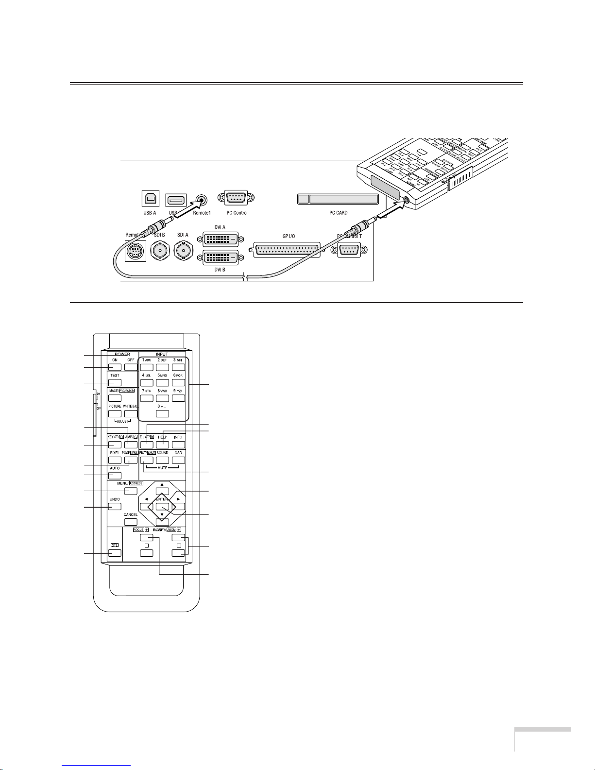
NOTE
• For operation with the remote control, be sure to connect the remote control to your projector, using the
supplied remote control cable.
1. POWER ON button
Operate this button to turn on the power to your projector.
Press it two seconds or longer.
When turning on the power to your projector, first set the
main power switch to ON, which puts your projector on
standby. (See page 17)
2. POWER OFF button
Operate this button to turn off (standby) the power to your
projector. Press it two seconds or longer.
3. Numeric buttons (1 to 0 buttons)
Use these buttons to enter alphanumeric characters. (See
page 25)
4. TEST button
• Press this button, and a test pattern will be displayed.
5. KEYSTONE button
Press the KEYSTONE (R) button while depressing the CTL
button, then the red (R signal) of the test pattern will be
turned off temporarily. Press this button again while
depressing the CTL button, and the red (R signal) will be
projected again.
2
1
4
6
5
9
11
12
16
15
19
3
7
8
10
13
14
18
17
Page 28

12
Checking the Supplied Items and the Names of the Projector Parts
6. AMPLITUDE button
Press the AMPLITUDE (G) button while depressing the CTL button, then the green (G signal) of
the test pattern will be turned off temporarily. Press this button again while depressing the CTL
button, and the green (G signal) will be projected again.
7. ENTRYLIST button
Press the ENTRYLIST (B) button while depressing the CTL button, then the blue (B signal) of the
test pattern will be turned off temporarily. Press this button again while depressing the CTL button,
and the blue (B signal) will be projected again.
8. HELP button
• Press this button, and input the menu item number by numeric buttons, it can be jumped to the
menu item (Direct menu selection function). If you want to the menu item number, see page
26-28.
9. POSITION button
Press the POSITION (LENS) button while depressing the CTL button, to make lens shift adjustment.
(See page 20)
10. PICTURE MUTE button
• Press this button to turn off image projection temporarily. Press it again, and the image will
be projected again.
• Press the PICTURE MUTE (SHUTTER) button while depressing the CTL button, then the
lens shutter will operate to shut off the light for projection. Press this button again while
depressing the CTL button to cancel the operation of the lens shutter.
NOTE
• When the GPIO control is in “Enable,” the PICTURE MUTE function will not work.
11. AUTO button
Press the AUTO button while depressing the CTL button, to store lens position shift in your projector
(lens memory function).
12. MENU button
Operate this button, and menus for various settings and adjustments will be displayed on the LCD
screen. (See page 23)
Page 29

13
Checking the Supplied Items and the Names of the Projector Parts
13. SELECT
buttons
• Press the SELECT button when a menu is being displayed, and a menu item can be
selected.
• Press the SELECT
button when a menu is being displayed, and a submenu will be displayed.
• Press the SELECT button when a menu is being displayed, and a menu one level above will
be displayed.
• During character entry, press the SELECT
button while depressing the CTL button, then
one character will be deleted.
14. ENTER button
Press the ENTER button, and the displayed menu item is actioned.
15. CANCEL button
Press the CANCEL button to return to the previous menu item.
16. UNDO button
Operate this button to reset to the state of adjustment and setting at the point when a menu is
displayed.
17. FOCUS Ⳮ/ⴑ button
Press the FOCUS +/- button while depressing the CTL button, to make lens focus adjustment. (See
page 20)
18. ZOOM Ⳮ/ⴑ button
Press the ZOOM +/- button while depressing the CTL button, to make lens zoom adjustment. (See
page 20)
19. CTL button
The CTL button is a shift function used to access alternative functions on other buttons.
NOTE
• The following buttons cannot be used with this projector:
WHITE BAL., ADJUST PICTURE, IMAGE, INFO., PIXEL., AUTO, MUTE SOUND, MUTE OSD
䢇 Notes for Use of the Remote Control:
• Do not drop or handle the remote control in a careless manner.
• Do not allow the remote control to be splashed with water or any other liquid. If the remote
should get wet accidentally, wipe the liquid off immediately.
• Be sure to use the remote control in a place free from heat or dampness as far as practicable.
• Do not set dry batteries on the remote control. You can operate the remote control of this
projector only when it is connected to the projector with the supplied remote control cable.
Page 30
14
Installation and Connection
2. Installation and Connection
2-1. Steps of setting up and connecting
Use the following steps for setting up your projector:
䢇 Step 1
Set up the screen and projector. (Contact your dealer to carry out the setup.)
䢇 Step 2
Connect cables to the image input terminals. (See this page)
Connect cables to the various control terminals. (See page 15)
䢇 Step 3
Connect the power cord. (See page 16)
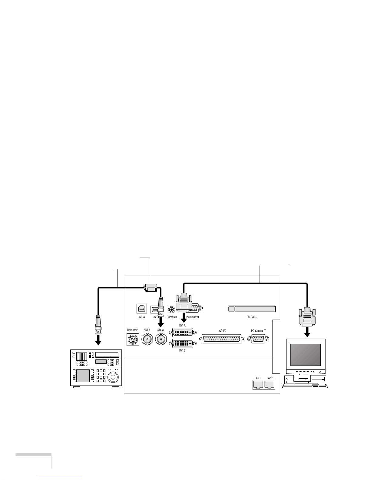
2-2. Connecting the image input terminals
Your projector has four image input terminals, namely, the HDSDI A input terminal, the HDSDI B input
terminal, the DVI-D A input terminal and the DVI-D B input terminal.
• HDSDI A/B input terminal (SDI-A/SDI-B) ........Inputs serial digital images from a Video Server
or Video source.
• DVI-D A/B input terminal (DVI-A/DVI-B) ........Inputs digital RGB signals from a PC.
Information for Reducing Radiation of Electromagnetic Waves
To reduce unnecessary radiation of electromagnetic waves, use the supplied ferrite clamp core.
BNC cable (75 ohm)
Ferrite clamp core
DVI-D
signal cable
Page 31
15
Installation and Connection
Installation Instructions
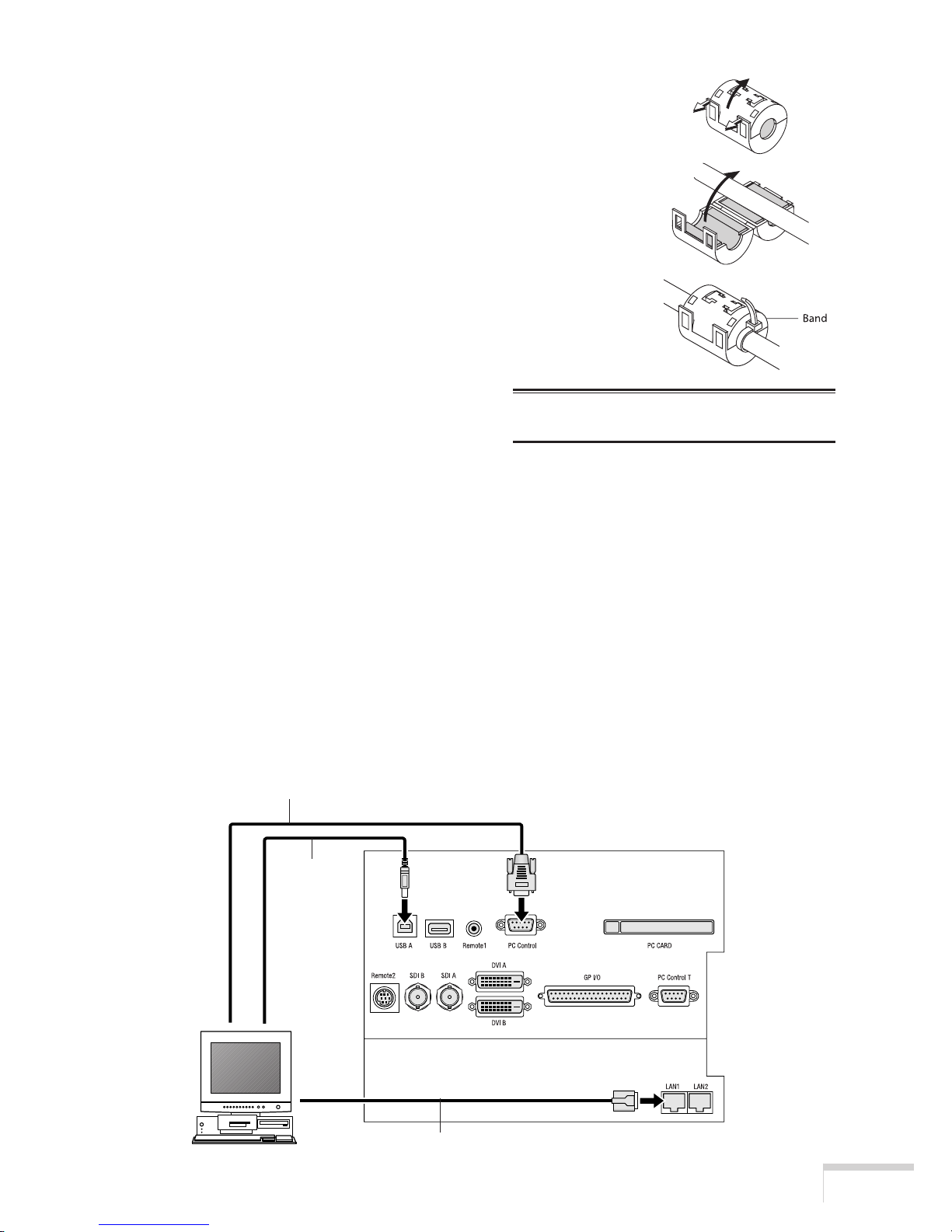
1. Open and attach the ferrite clamp core to the supplied BNC 75 ohm
cable as close as possible to the end that goes to the projector.
* Push the catch to open the ferrite clamp core.
2. Close the ferrite clamp core tightly.
3. Fix the supplied band to the signal cable as a stopper.
* Pull the end of the band to tighten it. Cut off the surplus of the
band.
2-3. Connecting the various control terminals
For control, your projector comes with such ports as the USB ports (type A/type B), the PC control
terminal and the Ethernet port (RJ-45).
• USB port (Type A) (USB A) ........................ For future extension.
• USB port (Type B) (USB B) ........................ Use this port when controlling the projector in USB
connection from a PC.
• PC control terminal (PC CONTROL).......... Use this terminal when controlling the projector in
serial connection from a PC.
• Ethernet port (LAN1, LAN2) ...................... Use this port when controlling the projector in LAN
connection from a PC.
NOTE: Be sure to use the ferrite clamp core
at the end of the BNC 75 ohm cable.
USB cable
LAN cable
RS-232C
Page 32
16
Installation and Connection
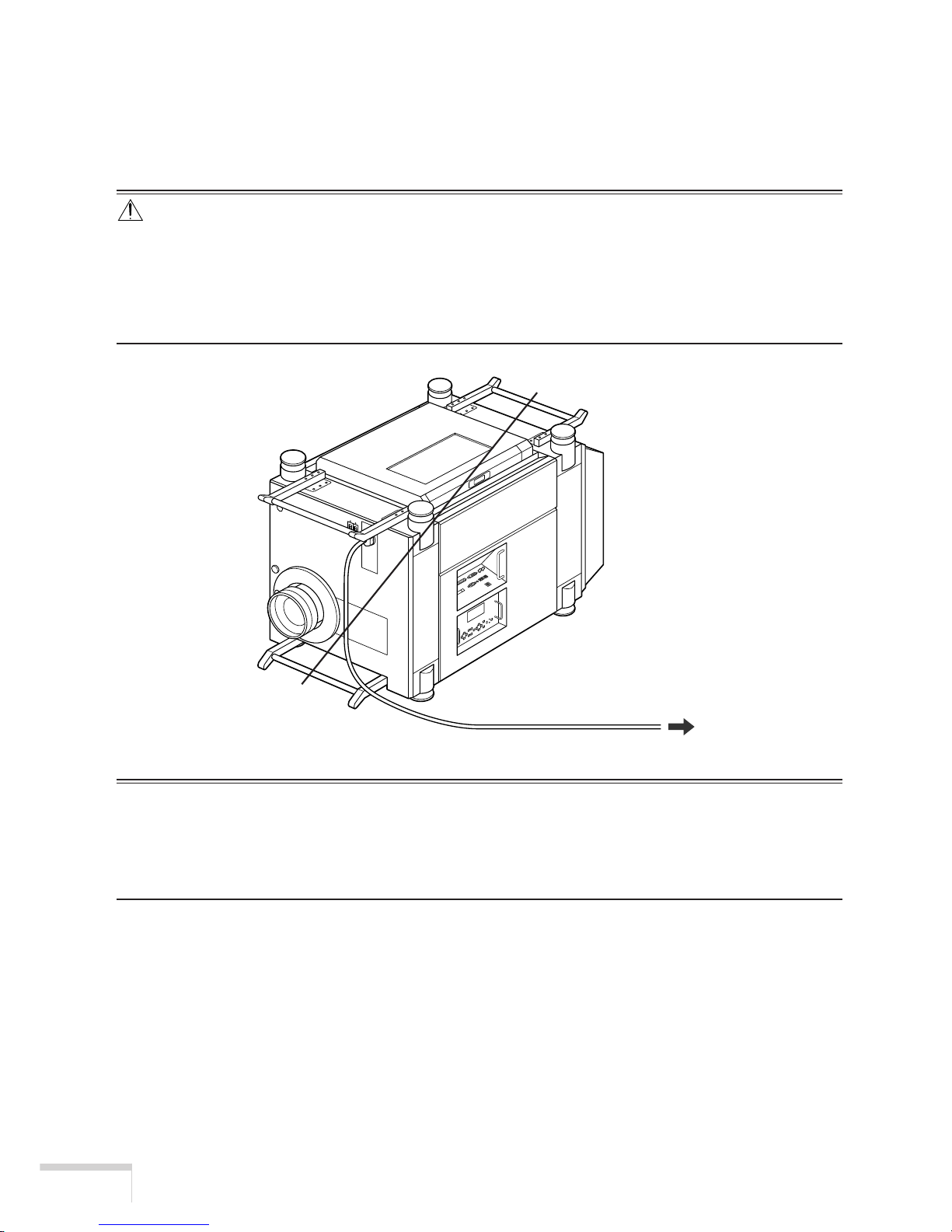
2-4. Connecting the power cord
After making certain that the main power switch of your projector is OFF, connect the power cord to a
200 to 240VAC three-prong outlet (grounded).
CAUTION
• Please contact your dealer/distributor to perform the wiring for connection of the power cord to your projec-
tor.
• Be sure to ground the equipment to ensure safety.
To avoid electric shocks, request a professional to carry out the grounding.
Be sure to perform earth connection before inserting the power plug into the wall outlet.
NOTE
• In the following instances, do not disconnect the power plug from the outlet. Otherwise, trouble may occur:
• When the fan is running (for about three minutes) after the power is turned off.
• When using a Flash Memory card or LAN card, the card may be damaged.
200-240 VAC
three-prong outlet
Page 33

17
Projection of Images (Basic Operation)
3. Projection of Images (Basic Operation)
3-1. Steps of projecting images
This section suggests four steps to a process.
䢇 Step 1
Turn on the power to the projector. (See this page)
䢇 Step 2
Select an input signal. (See page 19)
䢇 Step 3
Adjust the position and size of the projected screen. (See page 20)
䢇 Step 4
Turn off the power to the projector. (See page 21)
3-2. Step 1: Turning your projector on
Preparation: Please read “2. Installation and Connection” (See page 14) and then request your dealer/
distributor to conduct the setting up and connection for you.
NOTE
• Make certain that the main power switch is OFF when you connect the power cord to an AC outlet or discon-
nect the power cord from it.
Connection or disconnection of the power cord with the main power switch ON may cause projector trouble.
• Be sure to turn your projector on or off in two steps of operation with the “main power switch” and the
“POWER button” (“POWER ON/OFF button” on the remote control).
䢇 Turning power on (See page 18)
[1] Set the main power switch to ON.
Your projector is set in a standby state.
[2] Press the POWER button (POWER ON button on the remote control) two seconds or longer.
Your projector is turned on.
䢇 Turning power off (See page 21)
[1] Press the POWER button (POWER OFF button on the remote control) two seconds or longer.
Your projector is set in a standby state.
[2] When the fan has stopped running, set the main power switch to OFF.
Your projector is turned off.
Page 34
18
Projection of Images (Basic Operation)
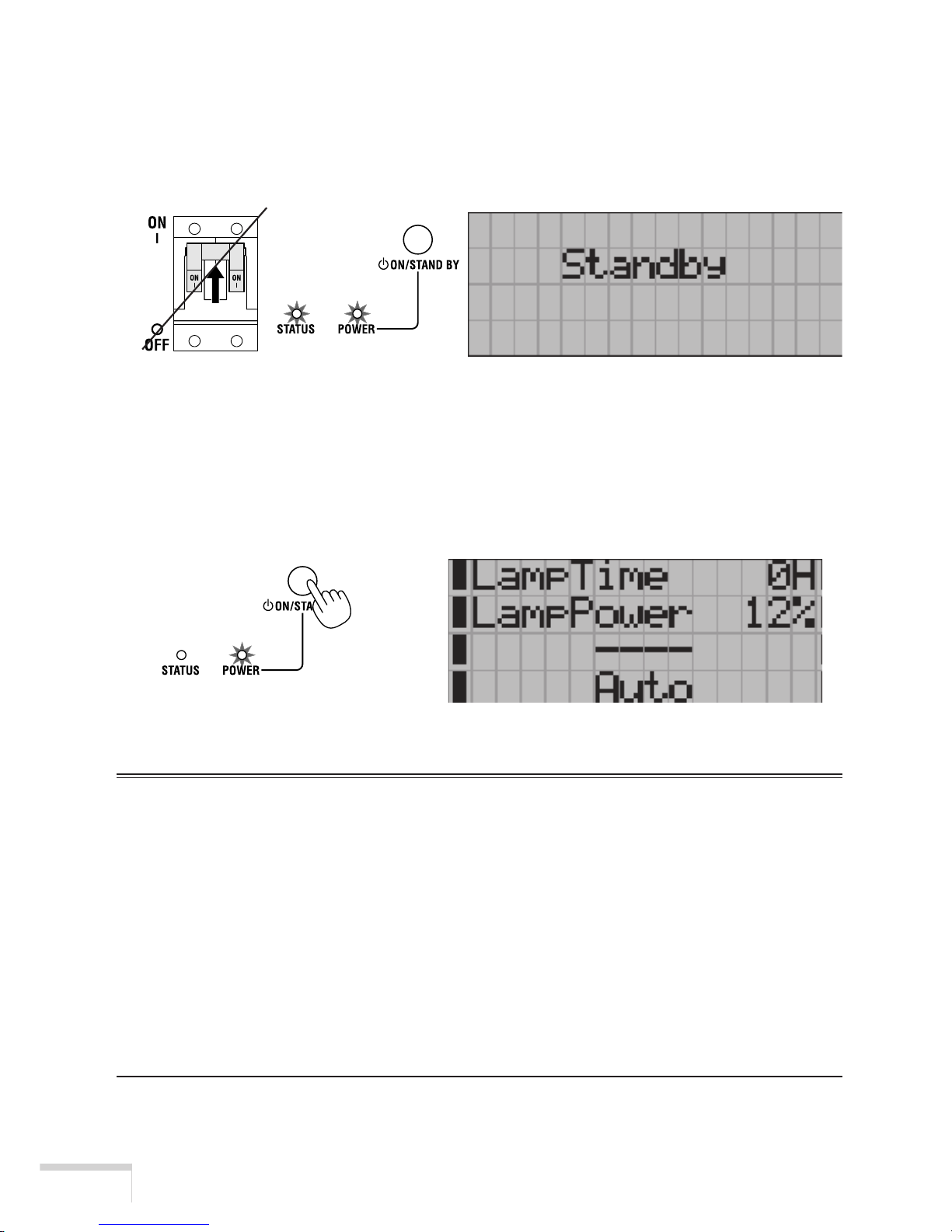
1 Set to ON the main power switch, which is located in the upper
position (lower position for inverted installation) on the front of your
projector.
The POWER indicator of the projector lights up orange, and the STATUS indicator of the projector
lights up green (standby state).
2 Press the POWER button on the control panel of your projector two
seconds or longer.
Your projector is turned on, and the screen glows light about 30 seconds later.
The POWER indicator of the projector lights up green.
• When controlling with the remote control, press the POWER ON button two seconds or
longer.
NOTE
• While your projector is on, be sure to have the lens cap removed from the lens.
Otherwise, the lens cap may get deformed due to a heat buildup.
• In the following instances, the power to your projector cannot be turned on even if you press the POWER
button:
• When the inside temperature is abnormally high. The protective function prevents power from turning on.
Wait some time (until the projector inside cools down) and then turn on the power.
• When the lamp is at the end of its life. Power will not turn on. Replace the lamp with a new one.
• When the STATUS indicator is blinking without the lamp lighting up after power-on. Your projector may
be in trouble. Check the error display on the LCD screen and contact your dealer/distributor for instructions.
• Note that the image may sometimes flicker until the lamp has stabilised (3 to 5 minutes) after power-on. This
is due to the characteristics of the lamp and is no trouble of your projector.
Page 35
19
Projection of Images (Basic Operation)
3-3. Step 2: Selecting the title of input signal
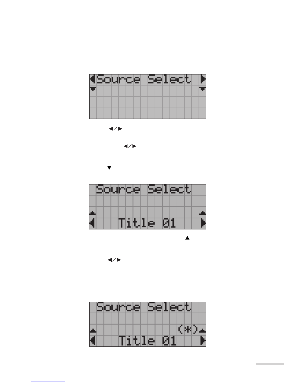
1Turn on the power to a PC or other source connected to your
projector.
2 Press the MENU button.
3 Press the SELECT button to display “Source Select” on the
LCD screen.
• At each press of the SELECT button, the display will cycle as “Source Select” ←→
“Setup” ←→ “information.”
4 Press the SELECT button.
The title of input signal is displayed.
• When you have made a wrong selection, press the SELECT button. A return will be made to
the previous menu.
5 Press the SELECT button to display the “title of the signal to
be projected” on the LCD screen.
6 Press the ENTER button.
The title of the signal to be projected is selected.
• The “(*)” mark on the liquid crystal display indicates that this is the currently selected item.
Page 36
20
Projection of Images (Basic Operation)
3-4. Step 3: Adjusting the position and size of projected screen
䡵 Displaying the test pattern
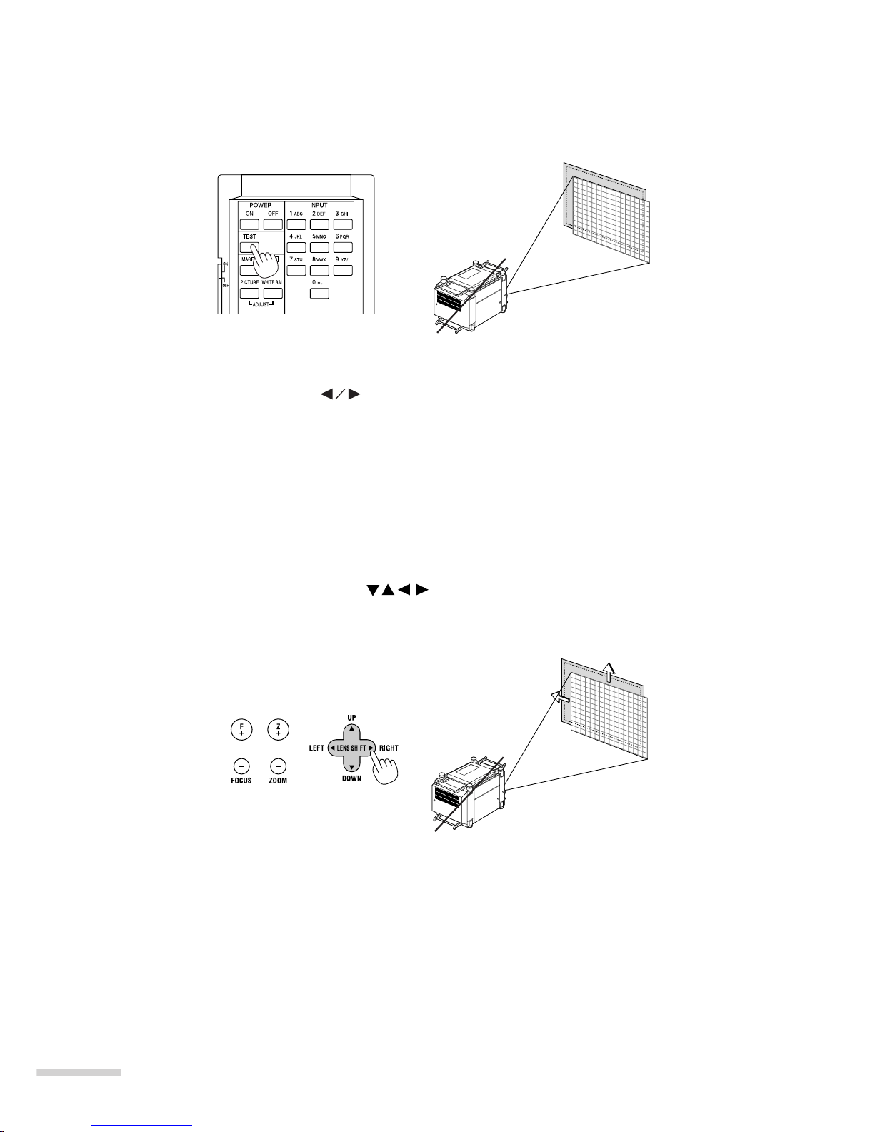
1 Press the TEST button on the remote control.
The mode for selecting the test pattern is set.
2. Press the SELECT button.
The display of the test pattern name on the liquid crystal display switches.
3. Display on the liquid crystal display the name of the test pattern to
be projected, then press the ENTER button.
• To cancel the test pattern display, select a different signal to be projected.
䡵 Adjusting the position of projected screen (Lens shift)
1 Press the LENS SHIFT
buttons while depressing the CTL
button, on the control panel of your projector as required.
The position of the projected screen will move downward, upward, left or right.
Page 37
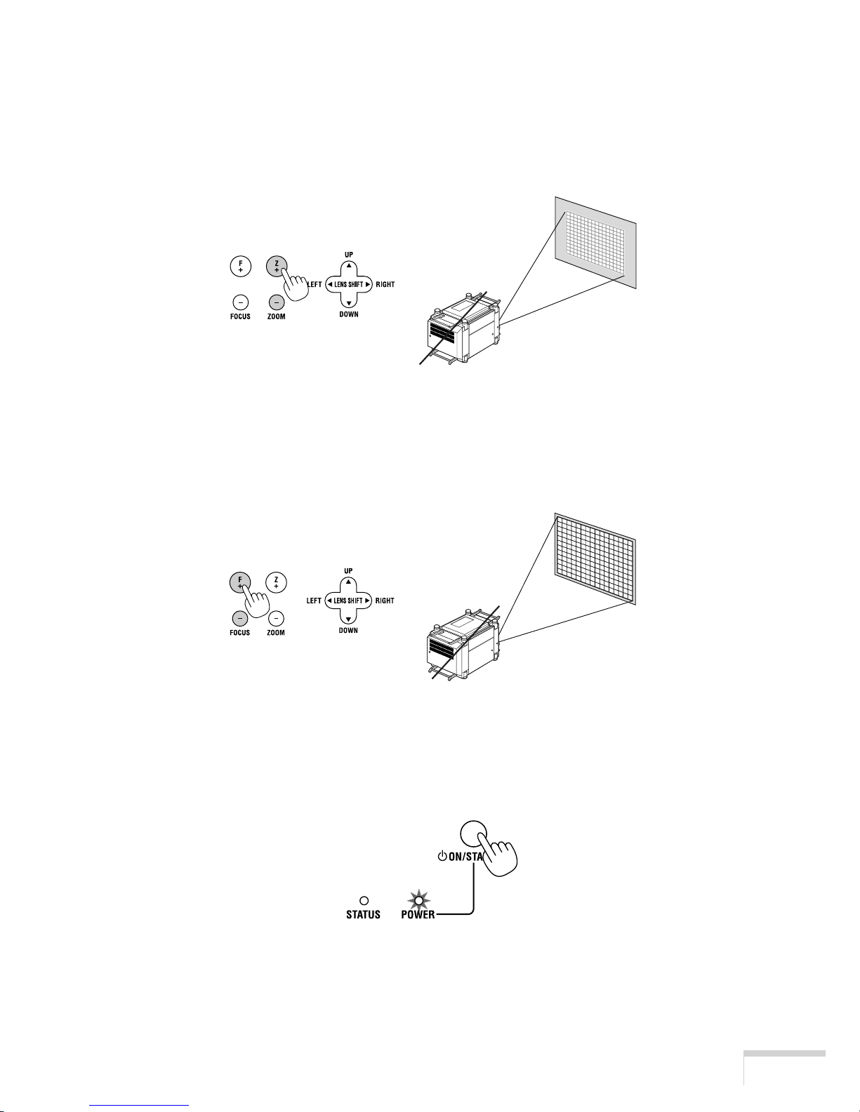
21
Projection of Images (Basic Operation)
䡵 Fine adjustment of the size of projected screen (Zoom)
1 Press the ZOOM +/− buttons while depressing the CTL button, on
the control panel of your projector as required.
• When controlling with the remote control, press the ZOOM +/- button while depressing the
CTL button.
䡵 Focusing the projected screen (Focus)
1 Press the FOCUS +/− buttons while depressing the CTL button, on
the control panel of your projector as required.
• When controlling with the remote control, press the FOCUS +/- button while depressing the
CTL button.
3-5. Step 4: Turning your projector off
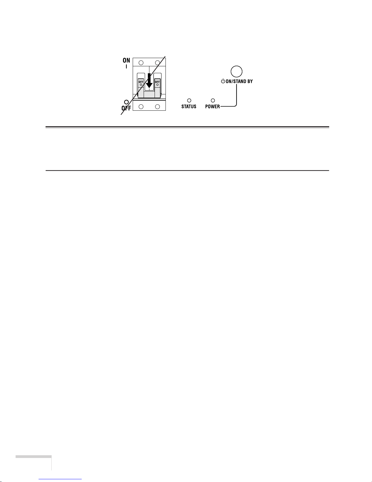
1 Press the POWER button on the control panel of your projector two
seconds or longer.
The power is turned off and the POWER indicator switches its color to orange (standby state).
• When controlling with the remote control, press the POWER OFF button two seconds or
longer.
Page 38
22
Projection of Images (Basic Operation)
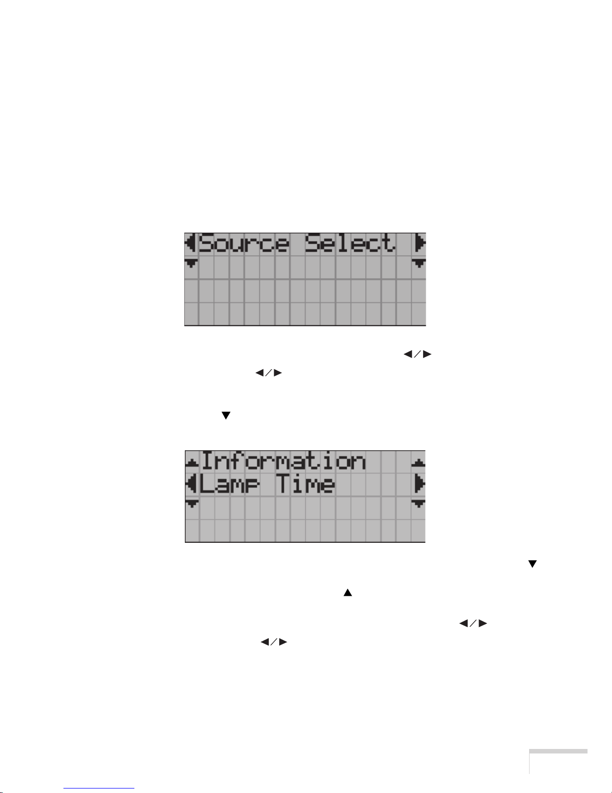
2 Set the main power switch to OFF.
The POWER indicator of your projector goes out and the main power supply is turned off.
NOTE
• In the following instances, do not turn off the main power switch or pull out the power plug from the outlet.
Otherwise, your equipment may develop trouble:
• When the fan is running (for about three minutes) after the power is turned off.
Page 39
23
Adjustment Menus
4. Using Menus
4-1. Basic operation with adjustment menus
You make adjustments of your projector by displaying menus on the LCD screen on the projector
body.
䡵 Operating menus
Preparation: Turn your projector on. (See page 17)
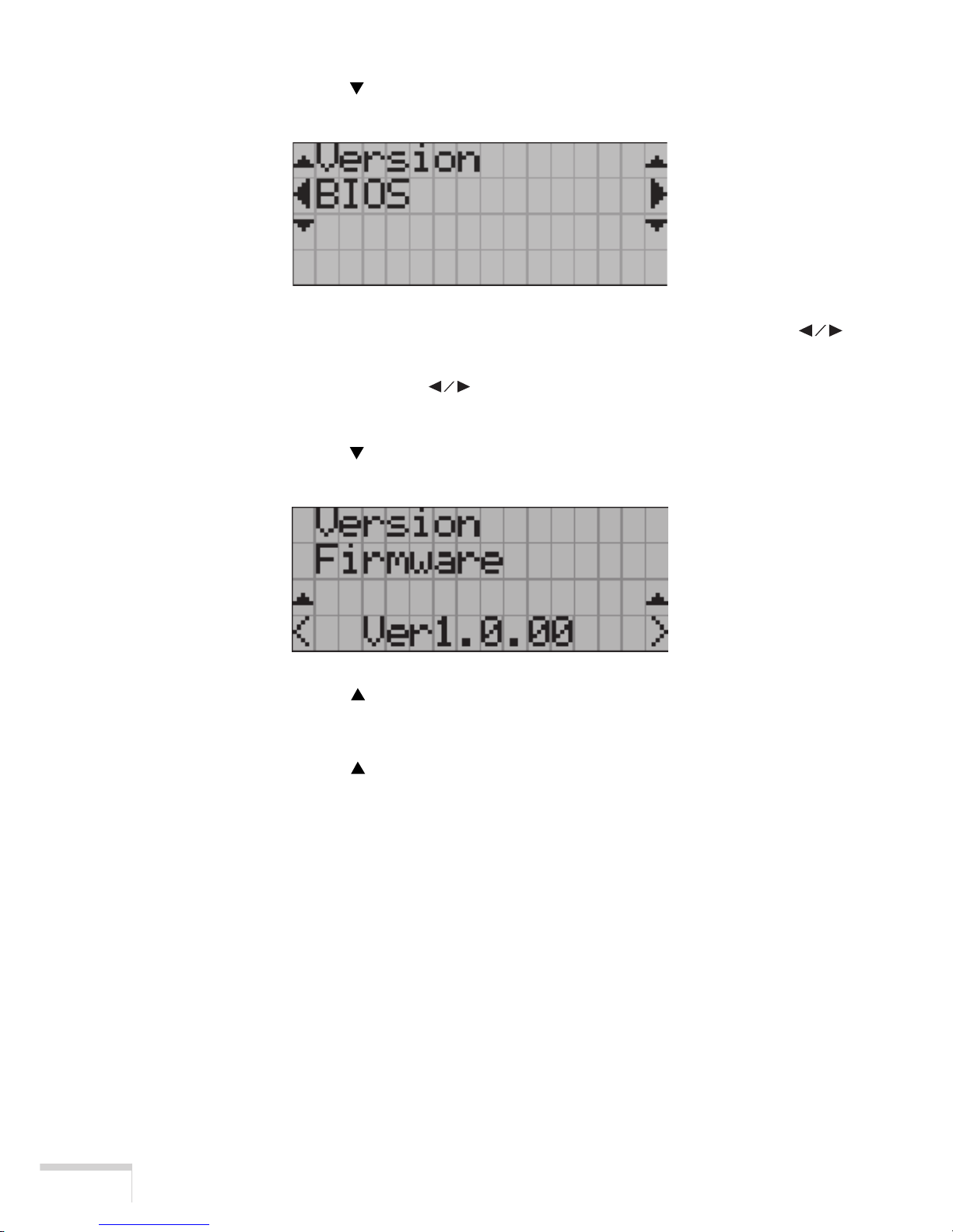
1 Press the MENU button on the control panel of your projector.
A menu is displayed on the LCD screen.
2 Select “Information” by pressing the SELECT button.
• At each press of the SELECT button, the display will cycle as “Source Select” ←→
“Setup” ←→ “Information.”
3 Press the SELECT button.
The submenu “Lamp Time” of “Information” is displayed.
• The menu item can be selected by pressing the ENTER button instead of the SELECT
button.
• To return to the previous state, press the SELECT
button or the CANCEL button.
4 Select the submenu “Version” by pressing the SELECT button.
• At each press of the SELECT button, the display will cycle as “Lamp Time”←→
“Version”←→ ”Error Code.”
Page 40
24
Adjustment Menus
5 Press the SELECT button.
The submenu “BIOS” another rank lower than “Version” is displayed.
6 Select the submenu “Firmware” by pressing the SELECT
button.
• At each press of the SELECT button, the display will cycle as “BIOS”←→
“Firmware”←→ “Data.”
7 Press the SELECT button.
A Firmware version is displayed.
8 Press the SELECT button.
A return is made to the menu one rank up.
9 Press the SELECT button.
A return is made to the menu still another rank up.
Page 41
25
Adjustment Menus
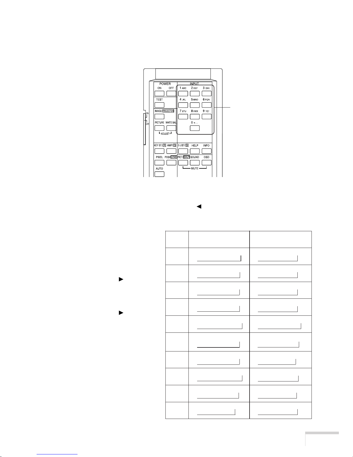
䡵 How to enter alphanumeric characters
Alphanumeric characters are entered for items, such as the title of input signal.
With this projector, the characters are inputted by pressing numeric buttons on the remote control.
By pressing the numeric buttons, the characters can be inputted as shown in the table below.
• To delete a character during entry, press the SELECT
button while depressing the CTL button.
[Example of Entry]
To enter “XGA” for instance, use the
following procedure:
(1) Press the “8” button three times.
V → W → X
(2) Press the SELECT
button.
(3) Press the “3” button.
XG
(4) Press the SELECT
button.
(5) Press the “1” button.
XGA
Numeric buttons
Numeric Press directly While depressing CTL
button button
1 A → B → C → 1 → a → b → c → ! →
↑↑
2 D → E → F → 2 → d → e → f → ” →
↑↑
3 G → H → I → 3 → g → h → i → # →
↑↑
4 J → K → L → 4 → j → k → l → $ →
↑↑
5 M → N → O → 5 → m → n → o → % →
↑↑
6 P → Q → R → 6 → p → q → r → & →
↑↑
7 S → T → U → 7 → s → t → u → ’ →
↑↑
8 V → W → X → 8 → v → w → x → ( →
↑↑
9 Y → Z → / → 9 → y → z → ? → ) →
↑↑
0 * → , → . → 0 → ; → : → + → _ →
↑↑
Page 42
26
Adjustment Menus
Data
Panel Key Lock
Enable
ON/OFF Timer
Time
Title Delete
Disable
Factory Default
All Data
Source Select
Projector Setup
Setup
Connection
Lamp Hour Meter
Lamp Time
Information
Version
BIOS
Remaining Time
Title Setup
Title Select Title Make
Date
Preset
Date/Time
Firmware
Error Code
Only Title
A B C D E
Execute Switch
Status
ActiveInactive
Ver 1.00
Ver 1.0.00
Ver.1.0.00
No Error
IP Address
0.0.0.0
Projector Control
0.0.0.0
TI Control
0 Hour 100%
[00:00:00][00/00/00( )]
(list of Timer)
MCGD File Select
Test Pattern Setup
File Name
TCGD File Select
File Name
000
003
084
034 085 086
033
050 051
052
032
048
049
002
008
007
027
029
028
026
030 031
087
088
089
006
012
Create PCF
Create SOURCE
SOURCE Name Input
[ ]
Aspect Ratio
1.0/1.25/1.33/1.42/1.5/1.78/1.85/2.35
067
Position -H- Position -V-
Image Input Size -H-
-4096~4095 -4096~4095
0~65535068
069 070
PCF Name Input
[ ]
Image Input Size -V-
0~65535
071
Create File
090
066
MMS Status
MMS -1 MMS -2
099
StatusIP Address
Not Use0.0.0.0
104
105
IP Address Status
0.0.0.0 Not Use
100
102
103
101
F G H
MENU button
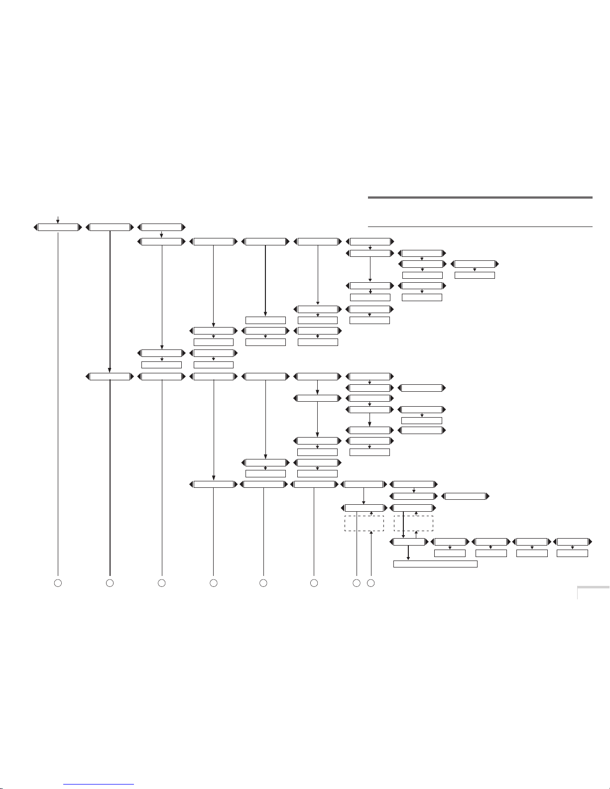
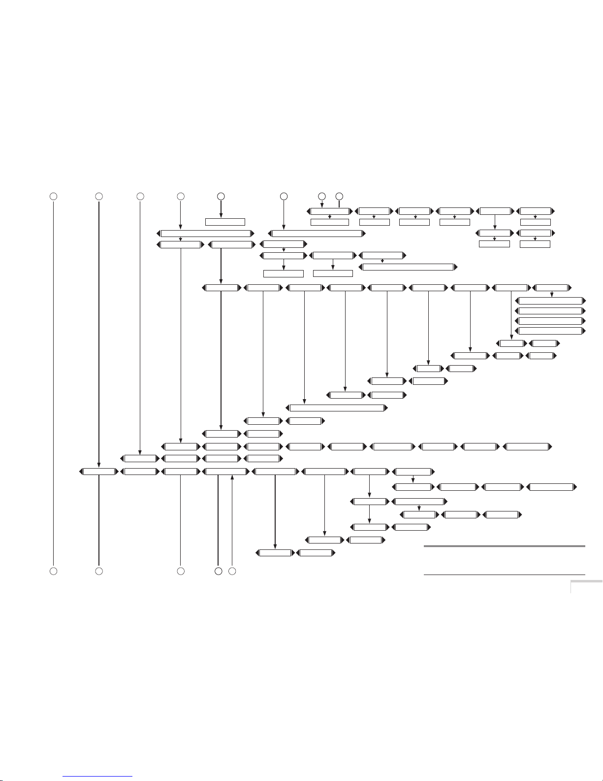
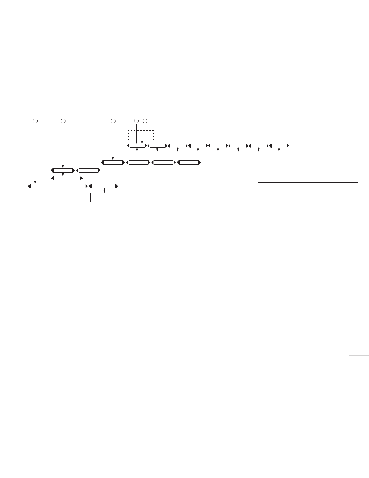
4-2. Table of adjustment menus
NOTE
• The number at the left side of each menu item is a number of a “Direct menu selection function”.
(See "HELP button" on page 12.)
Page 43
27
Adjustment Menus
Invert
Lamp Setup
Image Scaling
(Lamp Auto)
Pull down offset
Image Orient
Process Path
Turret Control
3=4:4:4 Packed, 10bits/color
F1 ~ F5
Pull down Seq.
1=4:2:2 Unpacked, 10bits/color
Pull down Re-sync
DisableEnable
4=4:4:4 Packed, 12bits/color
A B C D E
SMPTE Field bit
DisableEnable
Normal
DVI-A292-A 292-B
96004800 19200 38400
292-Dual
Non Cinema
2:2 3:2
Cinema
TurretCreate MCGD
Shutter Mode
On Off
Lens 2Lens 1No Lens
Turret Reference Select
Turret Title Select
Enable
No Lens
Auto
Disable
2=4:2:2 Packed, 12bits/color
Lens 2
Image Filter Source Type
Manual
Lens 1
GPIO Control
Disable Enable
038
044
043
040
039
024
037
005
083
022
042
041
096
095
094
DVI-Dual/TwinDVI-B (MMS-2)(MMS-1) (MMS-1(Dual))
091
093
092
File Name
045
screen file1 ~ screen file3
File Name
046
047
Signal Config
Signal Port Select
Title Name001 ~ Title Name100
Data File Select
MCGD File select
PCF File select
Screen File Select
[ ]
011
010
009
013
025
SOURCE File Select
File Name File Name
File Name
File Name
056
055
057
CSC File Select
LUT-AL File Select
LUT-CLUT File Select LUT-DG File Select
TCGD File Select
File Name
058 059
061
File Select
Set Parameter
-4.000~3.999
File Name
060
062
063
Title Name001 ~ Title Name100
F G H
I J MK L
MMS-1&MMS-2Not Use
MMS Control
098
MMS-1 MMS-2
NOTE
• The number at the left side of each menu item is a number of a
“Direct menu selection function”. (See "HELP button" on page 12.)
Page 44
28
Adjustment Menus
Ceiling Rear Desktop Rear
Desktop Front
Ceiling Front
Red-X-
0.000~0.999
Red-Y-
0.000~0.999
Green-X-
0.000~0.999
Green-Y-
0.000~0.999
Blue-X-
0.000~0.999
Blue-Y-
0.000~0.999
White-X-
0.000~0.999
White-Y-
0.000~0.999
018
074
075
076
077
078 07 9 080 081 082
3% ~ 100%
Adjust Auto
TEST Pattern
OFF/Alignment/Convergence/H-Ramp/RGB-Black/RGB-Blue/RGB-Green/RGB-Red/RGB-White/
Y-Color Bars/YCbCr-Blue/YCbCr-Green/YCbCr-Red/YCbCr-White/RGB-CROSS/RGB-50%-White
035
016
004
Title Name001 ~ Title Name100
MCGD Name Input
[ ]
I J MK L
001
NOTE
• The number at the left side of each menu item is a number of a
“Direct menu selection function”. (See "HELP button" on page 12.)
Page 45
29
Adjustment Menus
4-3. Source Select
Select the title of the signal to be projected by using Source Select.
Up to a hundred titles can be saved. (See page 19)
4-4. Setup
䡵 Projector Setup
䢇 Lamp setup
The brightness of the lamp is adjusted in 31 levels.
• Adjust ................ Select from 3% to 100%.
• Auto ................... Adjustment is made automatically.
䢇 Lamp Auto
The initial setting for auto adjustment of lamp brightness is made.
䢇 Image Orient
Make a selection according to the setup position of your projector and screen.
WARNING
Please request your dealer/distributor to set up your projector.
Never carry out the setup by yourself.
A fall or other accidents may occur to cause injury.
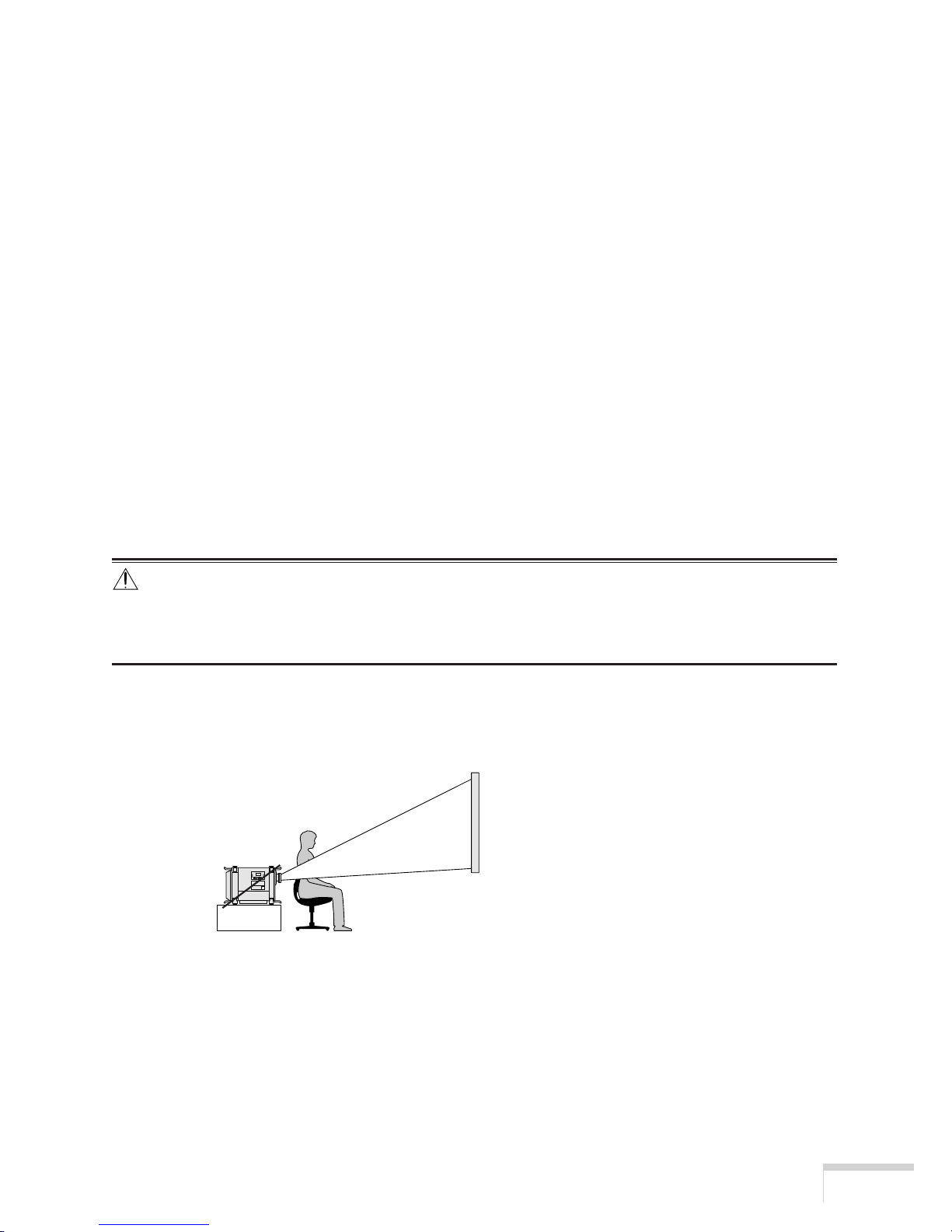
• Desktop Front
The projector is installed in a normal position, and projection is made from front of the screen.
Page 46
30
Adjustment Menus
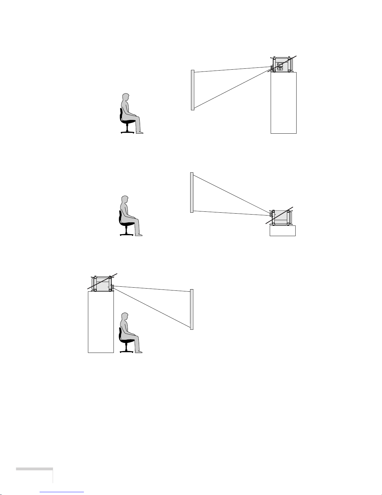
• Ceiling Rear
The projector body is installed upside down, and projection is made from behind the screen.
• Desktop Rear
The projector is installed in a normal position, and projection is made from behind the screen.
• Ceiling Front
The projector body is installed upside down, and projection is made from front of the screen.
䢇 Create MCGD
This is a function for adjusting chromaticity by inputting optical characteristics for your projector.
Please request your dealer/distributor to perform the setting.
䢇 Shutter Mode
The lens shutter function will be activated during the switching of signals.
Please request your dealer/distributer to perform the setting.
Page 47

31
Adjustment Menus
䢇 GPIO Control
Set this control to “Enable” when the projector is to be controlled by the External Control terminal
(GP I/O). With “Enable” set, the projector does not accept commands issued using the control
panel buttons, remote control unit or computer.
䢇 Turret
Control of the turret to which the anamorphic lens is mounted.
䢇 MMS Control
Control of input signals when a separately sold MMS 1000 is connected.
䡵 Connection
The transmission speed (bps) is selected for your projector and a PC when they are connected by a
commercially available RS-232C straight cable.
Make a selection from among 4800/9600/19200/38400.
䡵 Title Setup
This is for the setting of input signal.
䢇 Title Select
Set an input terminal and various modes for the saved title.
• Signal Port Select ......... Select an input terminal.
• Signal Config ................ Please request your dealer/distributor to make this setting.
• Data File Select............. Select “PCF” File, “MCGD” File or “Screen” File.
䢇 Title Make
The title of input signal is saved.
Up to 14 alphanumeric characters can be entered.
Up to a hundred titles can be saved in your projector.
䢇 Title Delete
The saved title is deleted.
䢇 Create File
This is a function for setting various data for signals to be projected.
Please request your dealer/distributer to perform the setting.
䢇 Factory Default
The settings are reset to the ones at the shipment of your projector from the factory.
• All Data ............. Reset all the settings to the ones at the shipment from the factory.
• Only Title........... Reset the title settings only to the ones at the shipment from the factory.
Page 48

32
Adjustment Menus
䡵 Test Pattern Setup
Use this function to set up the color of test pattern.
䡵 Date/Time
The timer function is set.
䢇 Preset
The present date and time are set.
• Date..........Set the present date.
• Time ......... Set the present time.
䢇 ON/OFF Timer
The on/off timer is set.
• Execute switch ........Run the set program.
• Status ......................Displays the current program.
䡵 Panel Key Lock
The control buttons on your projector are locked to disable.
• Enable ........... Enable a lock on the control buttons on your projector.
• Disable .......... Disable the lock on the control buttons.
Keep pressing the CANCEL button 10 seconds or longer, and menu
operation can be performed by temporarily disabling the lock on the control
buttons.
4-5. Information
Lamp time, version information, error codes, etc., are displayed.
䡵 Lamp Time
Elapsed time of the lamp in use is displayed.
䢇 Lamp Hour Meter
Elapsed hours of the lamp in use is displayed.
䢇 Remaining Time
The remaining time (%) of the lamp in use is displayed.
䡵 Version
Various versions are displayed.
Page 49

33
Adjustment Menus
䢇 BIOS
The BIOS version for your projector is displayed.
䢇 Firmware
The Firmware version for your projector is displayed.
䢇 Data
The Data version for your projector is displayed.
䡵 Error Code
When an error occurs, the error code is displayed.
Please see the Appendix for error codes.
䡵 IP Address
Displays the IP address set in your projector.
䡵 MMS Status
Indicates the status of the MMS 1000 connected to the iS8-2K.
Page 50

34
Maintenance of Your Projector
5. Maintenance of Your Projector
CAUTION
• Please request your dealer to perform lamp replacement, filter replacement and cleaning of the projector
inside.
5-1. Cleaning the cabinet
Be sure to disconnect the power plug from the outlet before carrying out maintenance of your
projector.
• Wipe with dry soft cloth without nap.
When the cabinet is excessively dirty, wipe with cloth well wrung after being wetted with a
neutral detergent diluted with water and then finish up with dry cloth.
When you use a chemical dustcloth, follow the instructions in the manual attached to it.
• Do not use a solvent, such as thinner or benzine. The coating may deteriorate or peel off.
• When removing dust on the ventilation opening, suck it off using an adapter with a brush on a
vacuum cleaner. Never allow the cleaner without an adapter to come in direct contact or use a
nozzle adapter in cleaning.
• Clean the ventilation opening at regular intervals. Dust, if allowed to accumulate there, may
cause heating inside, which leads to functional trouble. The interval, which can vary with the
location of your projector, is about 100 hours.
• Do not damage the cabinet by scratching it or allowing hard objects to hit it.
• Please consult your dealer/distributor about the cleaning of the projector inside.
NOTE
• Do not allow insecticide or other volatile liquid to splash on the cabinet, lens or screen.
Also, do not allow any rubber or vinyl object to remain in contact with the cabinet for a long time. The coating
may deteriorate or peel off.
Page 51
35
Maintenance of Your Projector
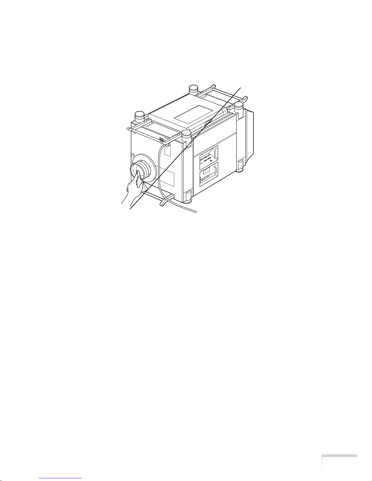
5-2. Cleaning the lens
Clean the lens the same way as with camera lens (using a commercially available camera
blower or cleaning paper for glasses). Take care not to damage the lens in the cleaning.
Page 52

Appendix
36
6. Appendix
Error code list
Please inquire your dealer/distributor about action to be taken for each error code.
Description is omitted for error codes 20 and on.
Error code
Error message description
1 Cover Open Cover is open.
2 Lamp Temp. Temperature (lamp temperature) is abnormal.
3 Fan Stop Fan has stopped.
4 Power Supply Power supply is abnormal.
5 Lamp Off Lamp does not light up.
6 LampTime Warn Lamp time is over. (Warning)
7 LampTime Over Lamp time is over. (Power off)
8 Lamp PS Temp. Temperature (lamp power inside temperature) is abnormal.
9 Set Temp. Temperature (set inside temperature) is abnormal.
10 DLP PS Engine power is abnormal.
11 DLP Comm TI-Engine communication error is detected.
12 Lamp Timer R Lamp Timer read error is detected.
13 Interlock Fail Inter Lock error is detected.
14 No Support Eng. DVI Dual Engine does not support.
15 Lamp Timer W Lamp Timer write error is detected.
20 System Fail
21 Self Test Fail
22 ARM Fail
23 DSP Fail
24 Interface FPGA Fail
25 Processor FPGA Fail
30 IB Diag Not Performed
31 IB FPGA Code Invalid
32 IB FPGA INITZ Fail
33 IB FPGA No-Load Set
34 IB FPGA DONE Fail
35 IB FPGA Reg R/W Fail
36 IB Framestore Test Fail
37 IB ANC FIFO Test Fail
38 IB RTC Serial # Fail
39 IB UART0 Fail
Page 53

Appendix
37
40 IB UART1 Fail
41 IB IIC Fail
42 IB Ethernet Fail
43 IB Sync-Serial Fail
44 IB File System Fail
45 IB Formatter Fail
46 IB Flash Protect Fail
47 IB GPI Macro Fail
48 IB A/D Macro Fail
60 PB Diag Not Performed
61 PB FPGA Code Invalid
62 PB FPGA INITZ Fail
63 PB McBSP XRDY Fail
64 PB FPGA Done Fail
65 PB FPGA Reg R/W Fail
66 PB Serial-ID Chip Fail
67 PB CLUT-SRAM Fail
68 PB OvFS-SDRAM Fail
69 PB Resizer FIR Fail
70 PB Resizer FIFO Fail
71 PB Other Fail
Page 54

Appendix
38
Troubleshooting
Before asking for repair, please check your connection, settings and operation once again. If the
trouble cannot be corrected by this checking, please contact your dealer/distributor for instructions
or repair.
The projector cannot be turned on.
• Check to see if the power plug is properly connected to the outlet.
• Make certain that the main power switch is ON.
• Check to see whether the panel key lock function is activated.
If so, the main unit’s control buttons are locked and do not work, but the projector can be
controlled using the remote control unit.
• The lamp may have completed its life span.
• When the inside temperature is too high, the protective function does not allow your projector
to be turned on. Wait some time and then turn it on.
The image cannot be projected.
• Check to see if the connected input has been selected.
• Check to see if the cable is properly connected to the input terminal.
• Check to see whether the lens shutter is closed.
• Check to see if the settings are all adjusted properly.
The image is distorted.
• Check to see if the projector is properly set up.
Thex image is blurred.
• Make certain that the lens is properly focused.
• Check to see if the screen and the projector are installed at correct angles.
• The projection distance may be larger than the focusing range.
• See if the lens and other parts have dew condensation on.
If the projector is turned on in a warm place after storage in a cold place, the lens and other
optical components inside may develop condensation on them. In such a case, please wait
several minutes until the condensation disappears.
The projector cannot be operated with the remote control.
• Make certain that the remote control is connected to the projector with the supplied remote
control cable.
The STATUS indicator blinks in red.
• Your projector may have trouble. Please contact your dealer/distributor for instructions.
Page 55

Appendix
39
Operation using an HTTP browser
Overview
The use of HTTP server functions will allow control of the projector from a web browser without the
installation of special software. Please be sure to use “Microsoft Internet Explorer 4.x” or a higher
version for the web browser. This device uses “JavaScript” and “Cookies” and the browser should be
set to accept these functions. The setting method will vary depending on the version of browser. Please
refer to the help files and the other information provided in your software.
NOTE
• The display’s or button’s response can be slowed down or operation may not be accepted depending the
settings of your network. Should this happen, consult your network administrator.
• The projector may not respond if its buttons are repeatedly pressed in rapid intervals. Should this happen, wait
a moment and repeat. If you still can’t get any response, pull out and then re-insert the LAN card.
Access is gained to the HTTP server functions by specifying
http:// <the projector’s IP address> /index.html
in the entry column of the URL.
Preparation Before Use
Make network connections and set up the projector and confirm that it is complete before engaging in
browser operations.
Operation with a browser that uses a proxy server may not be possible depending on the type of proxy
server and the setting method. Although the type of proxy server will be a factor, it is possible that items
that have actually been set will not be displayed depending on the effectiveness of the cache, and the
contents set from the browser may not be re-flected in operation. It is recommended that a proxy server
not be used unless it is unavoidable.
Handling of the Address for Operation via a Browser
Regarding the actual address that is entered for the address or entered to the URL column when operation of the projector is via a browser, the host name can be used as it is when the host name corresponding to the IP address of the projector has been registered to the domain name server by a network
administrator, or the host name corresponding to the IP address of the projector has been set in the
“HOSTS” file of the computer being used.
Example 1: When the host name of the projector has been set to “pj.nec.co.jp”, http://pj.nec.co.jp/
index.html is specified for the ad-dress or the entry column of the URL.
Example 2: When the IP address of the projector is “192.168.0.10”, access is gained to the HTTP server
functions by specifying http://192.168.0.10/index.html for the address or the entry column of the
URL.
Page 56
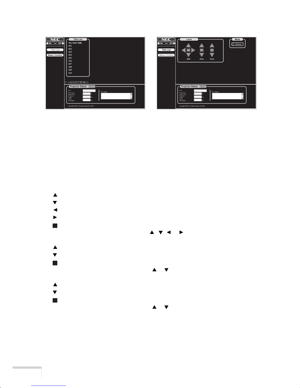
Appendix
40
Structure of the HTTP Server
Power: Controls the power to your projector.
ON ....................... Turns power on.
OFF ..................... Turns power off.
Title List: Displays the title set in the projector.
Click, and the title will be changed.
Basic Control: Displays the Basic Control item.
Lens: Controls the lens operation.
Shift:
..................... Shifts the projected screen upward.
..................... Shifts the projected screen downward.
.................... Shifts the projected screen leftward.
..................... Shifts the projected screen rightward.
..................... Stops the shifting.
* Shifting can also be stopped by clicking
, , or once again during the shifting.
Zoom:
..................... Zooms up the lens.
..................... Zooms down the lens.
..................... Stops the zooming.
* Zooming can also be stopped by clicking
or once again during the zoom up/down.
Focus:
..................... Focuses up the lens.
..................... Focuses down the lens.
..................... Stops the focusing.
* Focusing can also be stopped by clicking
or once again during the focus up/down.
Mute:
Picture ................. Click and the projected picture disappears. Click once again and the picture will
be projected again.
Page 57
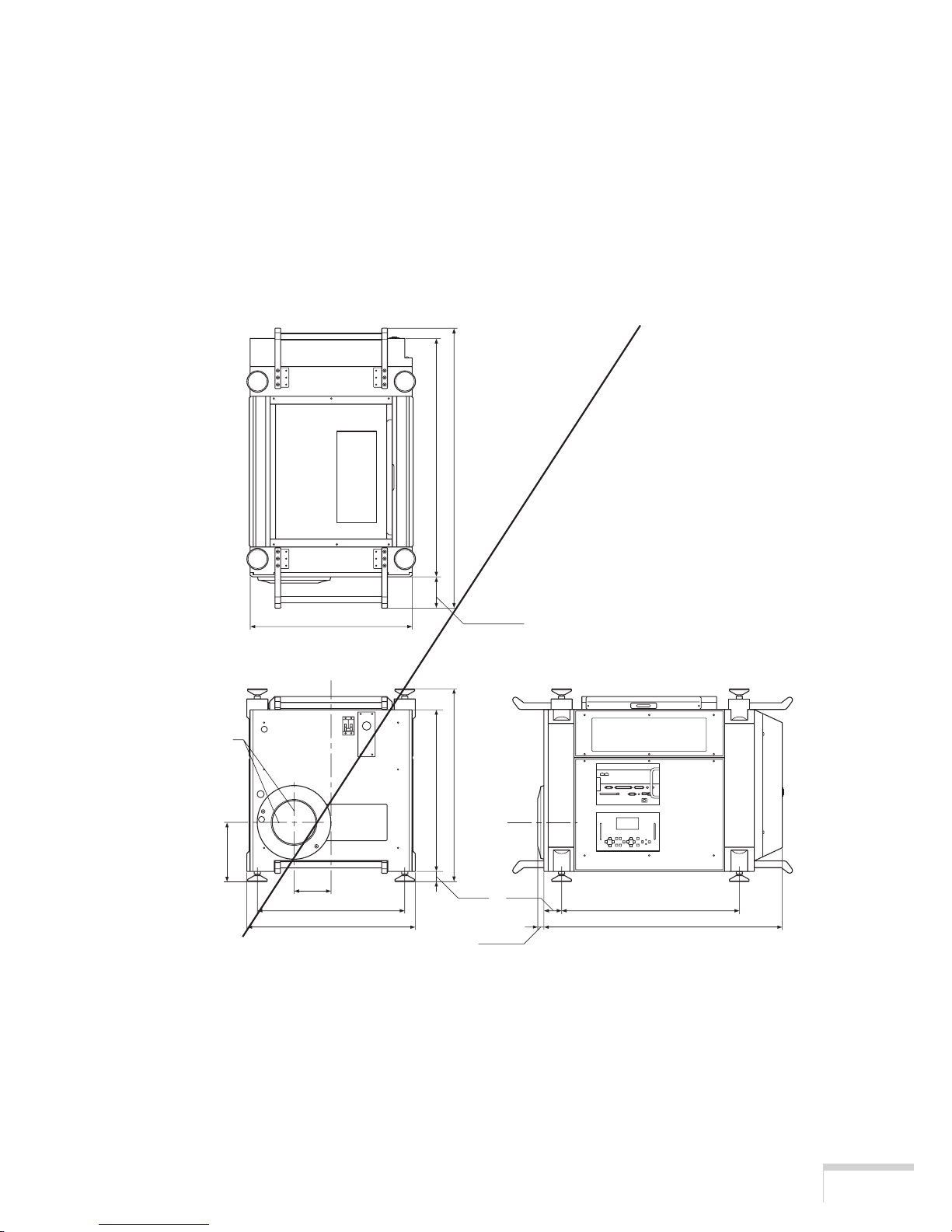
Appendix
41
Lens Center
(
5.20
)
210.9
(
8.31
)
525 (20.67
)
600 (23.63
)
(
1.44
)
575.7
(
22.67
)
687
(
27.05
)
111.3 (4.32
)
22 (0.87
)
(
2.49
)
132
36.5 63.2
633 (24.93
)
850 (33.47
)
850
(
33.47
)
997
(
39.26
)
577 (22.72
)
Outline Drawing
Unit: mm (inch)
Projector Status: This displays the condition of the projector.
Remaining Lamp Time .............Displays the remaining life of the lamp as a percentage.
Projector Usage .........................Displays how many hours the projector has been used.
Lamp Hour Meter .....................Displays how many hours the lamp has been used.
Error Status ............................... Displays the status of errors occurring within the projector.
Refresh ......................................Updates the display of the following conditions.
Page 58

Appendix
42
Specifications
Optical
Panel
*1
DMDTM .9" x 3
2048 x 1080 native resolution
Lamp
2.0kW Bubble Type Short Arc Xenon
Built in: Overheat Protection
Lamp Over-Usage Protection
Light Output
12ft-L (Max. Vista screen 10m (394inch) in width*2)
Brightness - Uniformity
Uniformity >80% edge to center
Contrast Ratio
More than 1000 : 1 Full On/Off
More than 400 : 1 ANSI
Lens Movement
Motorized Horizontal and Vertical Lens Shift
Motorized Zoom and Focus
Built in Lens Shutter
Electrical
Inputs
Digital I/O
RGB DIGITAL (2) DVI-D 24pin
TMDS specification
SDI (2) BNC
SMPTE 292M Level C, 4:2:2
PC Card (1) PCMCIA Data Back-up
External Control
RS232C (1) D-sub 9 pin
Remote Control (wired)
Ethernet Port (RJ-45)
USB Port (type B)
Power Requirement
200-240 VAC, 50/60Hz
Page 59

Appendix
43
Input Current
14 A
Power Consumption
2.8 kW
Mechanical
Installation
Orientation: Desktop/Front, Desktop/Rear, Ceiling/Front, Ceiling/Rear
Dimensions
23.7"(W) x 34.4"(D) x 27.1"(H) with lens hood and feet (not including handle)
600mm(W) x 872mm(D) x 687mm(H) with lens hood and feet (not including handle)
Net Weight
207.3lb (94Kg) (without lens)
Environment
Operational Temperature: 50 to 95 F / 10 to 35C,
Humidity: 20-80% non-condensing
Storage Temperature: -4 to 140 F / -20 to 60C
Humidity: 20-80% non-condensing
Regulations
Safety EMC
USA UL60950 FCC part15 Class A
Canada CSA60950 ICES-003 Class A
Europe EN60950 EN55022 Class A
EN55024
EN61000-3-2
EN61000-3-3
Oceania EN60950 AS/NZS CISPR.22:2002 Class A
Asia EN60950 CISPR. 22
*1 Permissible deviation for RGB convergence (Pixel deviation) is 1/2 pixel or less at center; 3/4
pixel or less around the perimeter when projection upward angle is 0° (without Anamorphic lens).
*2 Reference value.
Specifications are subject to change without notice.
Page 60

Appendix
44
Partie optique
Panneau
*1
DMDTM .9" x 3
Résolution naturelle 2048 x 1080
Lampe
Type bulle 2,0 kW au xénon à arc court
Protection surchauffe incorporée
Protection sur-utilisation de la lampe
Puissance
12ft-L(Ecran Vista 10m de large maxi.*2)
Luminosité - Uniformité
Uniformité > 80% des bords au centre
Rapport de contraste
Plus de 1000:1 Marche/arrêt à fond
Plus de 400 : 1 ANSI
Commande de l’objectif
Commande du mouvement horizontal et vertical de l’objectif à moteur
Commande du zoom et de la mise au point à moteur
Obturateur d’objectif incorporé
Partie électrique
Entrées
E/S numérique
RGB NUMERIQUE (2) DVI-D 24fiches
Spécifications TMDS
SDI (2) BNC
SMPTE 292M Niveau C, 4:2:2
Sauvegarde des données par carte PCMCIA PC (1)
Commande extérieure
D-sub 9 fiches RS232C (1)
Télécommande (par câble)
Port Ethernet (RJ-45)
Port USB (Type B)
Alimentation électrique
200-240 Vca, 50/60Hz
Page 61

Appendix
45
Intensité d’entrée
14 A
Puissance absorbée
2,8 kW
Partie mécanique
Installation
Orientation : Bureau/Avant, Bureau/Arrière, Plafond/Avant, Plafond/Arrière
Dimensions
600mm(l) x 872mm(p) x 687mm(h) avec le capot de l’objectif et le pied (poignée non cocmprise)
Poids net
94 kg (sans objectif)
Conditions ambiantes
Température de service : 10° à 35°C,
Humidité : 20-80% sans condensation
Température de magasinage: -20° à 60°C
Humidité : 20-80% sans condensation
Réglements applicables
Sécurité EMC
USA UL60950 FCC partie15 Classe A
Canada CSA60950 ICES-003 Classe A
Europe EN60950 EN55022 Classe A
EN61000-3-2
EN61000-3-3
Océanie EN60950 AS/NZS CISPR.22:2002 Classe A
Asie EN60950 CISPR. 22
*1 La déviation admissible pour la convergence RGB (déviation de pixel) est de 1/2 pixel ou moins au
centre et de 3/4 pixel ou moins à la circonférence quand l’angle de projection vers le haut est de 0º
(sans objectif anarmorphique).
*2 valeur de référence
Les spécifications sont sujettes à modification sans préavis.
Page 62

Appendix
46
Optik
Bildfläche
*1
DMDTM .9" x 3
2048 x 1080 Bildpunkte
Lampe
2,0 kW Blasen-Kurzbogen-Xenon
Integriert: Überhitzungsschutz
Lampenverwendungsschutz bei überschrittenen Betriebsstunden
Lichtleistung
12ft-L (Max. Vista-Bildschirm 10 m Breite *2)
Helligkeit — Gleichmäßigkeit
Gleichmäßigkeit > 80 % Kante zu Mitte
Kontrastverhältnis
Mehr als 1000 : 1 Voll Ein/Aus
Mehr als 400 : 1 ANSI
Linsenbewegung
Servo in Horizontal- und Vertikalrichtung
Motorzoom und -fokus
Integrierter Linsenverschluss
Elektrik
Eingänge
Digital I/O
RGB DIGITAL (2) DVI-D 24-pol
TMDS-Spezifikation
SDI (2) BNC
SMPTE 292M Level C, 4:2:2
PC-Karte (1) PCMCIA Daten-Backup
Externe Steuerung
RS232C (1) D-sub 9-pol
Fernbedienung (Kabel)
Ethernet Port (RJ-45)
USB Port (Typ B)
Stromversorgung
200-240 V Wechselspannung, 50/60Hz
Page 63

Appendix
47
Eingangsstrom
14 A
Leistungsaufnahme
2,8 kW
Mechanik
Installation
Ausrichtung: Desktop/Vorn, Desktop/Hinten, Decke/Vorn, Decke/Hinten
Abmessungen (B/T/H)
600 mm (B) x 872 mm (T) x 687 mm (H) mit Gegenlichtblende und Füßen (ohne Griff)
Gewicht
94 kg (ohne Linse)
Umgebungsbedingungen
Betriebstemperatur: 10 °C bis 35 °C
Feuchtigkeit: 20-80 % ohne Kondensatbildung
Lagerungstemperatur: -20°C bis 60°C
Feuchtigkeit : 20-80 % ohne Kondensatbildung
Verordnungen
Sicherheit EMC
USA UL60950 FCC Abschnitt 15 Klasse A
Kanada CSA60950 ICES-003 Klasse A
Europa EN60950 EN55022 Klasse A
EN55024
EN61000-3-2
EN61000-3-3
Ozeanien EN60950 AS/NZS CISPR.22:2002 Klasse A
Asien EN60950 CISPR. 22
*1 Die zulässige Abweichung für RGB-Konvergenz (Bildpunktabweichung) beträgt max. 1/2 Pixel in
der Mitte bzw. max. 3/4 Pixel im Randbereich bei einem Projektionswinkel von 0° (ohne
Anamorphot).
*2 Anhaltswert
Änderungen der technischen Daten jederzeit vorbehalten.
Page 64

TM
反射方式
TM
方式)
400:1以上
RGBDIGITAL(2)DVI-D24pin
TMDSspecification
PCカードスロット(1)PCMCIADataBack-up
外部コントロール
RS232C(1)D-sub9pin
Ethernetポート
USBポート
AC200〜240V,50/60Hz
Page 65

外形寸法
RGBのコ
Page 66

50
INDEX
- A -
Adapter 3
Air inlet 5
Air outlet 5
alphanumeric characters 25
Anamorphic lens mount 3
- B -
Back light switch 7
BIOS 33
- C -
Carrying handles 4
CompactFlash Memory card 3
Connection 14,31
Connection terminals 4,8
Control panel 4,6
Create MCGD 30
- D -
Data 33
Date/Time 32
DVI-D signal cable 3,14
DVI input terminal (DVI) 9
- E -
Error Code 36
Ethernet hub (LAN2) 10
Ethernet port (LAN1) 10
External control terminal (GP I/O) 9
External control terminal (REMOTE 2) 9
- F -
Factory Default 31
Feet 4
Ferrite clamp core 15
Firmware 33
Focus 7,13,20
-G-
GPIO Control 31
-H-
HDSDI A input terminal (SDI-A) 9
HDSDI B input terminal (SDI-B) 9
- I -
Image Orient 29
Information 32
IP Address 33
- L -
Lamp Auto 29
Lamp Hour Meter 32
Lamp setup 29
Lamp Time 32
LCD screen 6
Lens 4
Lens shift 6,12,20
- M -
Main power switch 4
- O -
ON/OFF Timer 32
- P -
Panel Key Lock 32
PC card slot 9
PC control terminal (PC CONTROL) 8
PC control terminal (PC CONTROL-T) 10
POWER button 7,11
Power cord 4,16
POWER indicator 7
Preset 32
Projector Setup 29
- R -
Remaining Time 32
Remote cable 3,11
Remote Control 3,11
Remote control terminal (REMOTE 1) 8
- S -
Setup 27
shafts 3
Shutter Mode 30
Source Select 29
STATUS indicator 7
Page 67

51
- T -
Test Pattern Setup 32
Title Delete 31
Title Make 31
Title Select 31
Title Setup 31
- U -
USB port (USB A) 8
USB port (USB B) 8
- V -
Version 32
- Z -
Zoom 6,13,21
Page 68

© NEC Viewtechnology. Ltd. 2004 Printed in Japan
Ver.1 5/04
Page 69

7N8Pxxxx
 Loading...