

Page 1

NEC Storage Manager
Configuration Setting Tool
User’s Manual (GUI)
IS007-10E
Page 2

© NEC Corporation 2001-2004
No part of the contents of this book may be reproduced or
transmitted in any form without permission of NEC Corporation.
The contents of this book may be modified without notice in the future.
Page 3

Preface
This manual describes how to perform the following by using the GUI (Graphical User Interface) on NEC Storage
Manager clients:
• Configure the NEC Storage series disk array subsystem.
• Refer to the disk array configuration information.
Remarks: The LD Administrator (ReallocationControl) and CachePartitioning are described in the “NEC Storage
Manager LD Administrator User’s Manual (IS037)” and “NEC Storage Manager Cache Partitioning User’s
Manual (IS038)”, respectively, from the NEC Storage Manager Ver3.3.
It is also possible to use the CLI (Command Line Interface) to configure the disk array subsystem or refer to the
configuration information. For details, refer to the “NEC Storage Manager Configuration Setting Tool User’s
Manual” (IS002).
As its readers, this manual is aimed at those who have professional knowledge of the disk array subsystem. For
information on the disk array subsystem functions, refer to the “NEC Storage Manager User’s Manual” (IS004) or
“NEC Storage Manager User’s Manual (UNIX)” (IS001) in accordance with your OS.
Refer to the “NEC Storage Manager Manual Guide” (IS901) for the overview of NEC Storage and the related
manuals.
Remarks 1. This manual explains functions implemented by the following program products:
• NEC Storage Manager and NEC Storage BaseProduct
• NEC Storage AccessControl
• NEC Storage DynamicDataReplication
• NEC Storage ReallocationControl
• NEC Storage RemoteDataReplication
2. This manual is applicable to the program products of the following versions:
• NEC Storage Manager Ver3.3
• NEC Storage BaseProduct Ver3.3
3. The NEC Storage Manager is referred to as iSM or Storage Manager in the text of this manual.
Also, the NEC Storage series disk array subsystem is referred to as a disk array.
4. The following descriptions in the text of this manual refer to the corresponding products.
Description Corresponding Product
Storage Manager NEC Storage Manager
AccessControl NEC Storage AccessControl
DynamicDataReplication NEC Storage DynamicDataReplication
ReallocationControl NEC Storage ReallocationControl
RemoteDataReplication NEC Storage RemoteDataReplication
Page 4
5. The following descriptions in the text of this manual refer to the corresponding manuals.
Description Corresponding Manual
User's Manual (UNIX) NEC Storage Manager User's Manual (UNIX) (IS001)
User's Manual NEC Storage Manager User's Manual (IS004)
Data Replication User's Manual
(Function Guide)
Snapshot User's Manual (Function
Guide)
6. Trademarks and registered trademarks
• HP-UX is a registered trademark of Hewlett-Packard Co. in the United States.
• UNIX is a registered trademark of The Open Group in the United States and other countries.
• Microsoft® and Windows® are trademarks or registered trademarks of Microsoft Corporation in the
United States and other countries.
• Solaris is a trademark or a registered trademark of Sun Microsystems, Inc. in the United States and
other countries.
• Linux is a trademark or registered trademark of Mr. Linus Torvalds in the United States and other
countries.
Other product names and company names, etc. are trademarks or registered trademarks of the
associated companies.
7. In this document, matters to which careful attention needs to be paid will be described as follows:
Be sure to observe the contents.
If the indications are ignored and the system is improperly operated, settings which have been already
made might be affected.
NEC Storage Manager Data Replication User's Manual
(Function Guide) (IS015)
NEC Storage Manager Snapshot User's Manual (Function
Guide) (IS030)
Type of Indication
Type Description
Describes contents which require special attention during operation.
Describes limitations to operation and similar information.
The First Edition in October 2001
The Tenth Edition in November 2004
Page 5

Contents
Part I Overview..................................................................................................................................................I-1
Chapter 1 Storage Overview............................................................................................................................................ I-2
1.1 Disk Array ................................................................................................................................................................ I-2
1.2 Disk Array Configuration......................................................................................................................................... I-4
Chapter 2 Overview of Disk Array Configuration Setting .........................................................................................I-21
2.1 Pool and RANK...................................................................................................................................................... I-22
2.1.1 Basic Pool.......................................................................................................................................................I-23
2.1.2 Dynamic Pool .................................................................................................................................................I-24
2.1.3 RANK............................................................................................................................................................. I-28
2.2 Logical Disk ........................................................................................................................................................... I-29
2.3 Spare....................................................................................................................................................................... I-30
2.4 Nickname................................................................................................................................................................ I-30
Chapter 3 Overview of AccessControl .......................................................................................................................... I-32
3.1 LD Set..................................................................................................................................................................... I-33
3.2 WWN Mode ...........................................................................................................................................................I-35
3.3 Port Mode ............................................................................................................................................................... I-37
Part II Installation.............................................................................................................................................II-1
Chapter 4 Configuration Setting and Access Control Installation ............................................................................ II-2
4.1 System Configuration..............................................................................................................................................II-2
4.2 Configuration Setting and AccessControl Installation ............................................................................................ II-2
Part III Application ..........................................................................................................................................III-1
Chapter 5 Operation Procedures .................................................................................................................................III-2
5.1 Initial Installation .................................................................................................................................................. III-2
5.1.1 Setting the Storage Manager.......................................................................................................................... III-3
5.1.2 Setting a Disk Array ...................................................................................................................................... III-3
5.1.3 Binding a Pool or RANK............................................................................................................................... III-3
5.1.4 Binding a Logical Disk.................................................................................................................................. III-4
5.1.5 Setting a Logical Disk Nickname .................................................................................................................. III-4
5.1.6 Installing the Access Control......................................................................................................................... III-4
5.2 Physical Disk Expansion ....................................................................................................................................... III-5
5.2.1 Binding and Expanding a Pool or RANK ..................................................................................................... III-5
5.2.2 Binding a Logical Disk.................................................................................................................................. III-6
5.2.3 Changing the Access Control Configuration ................................................................................................. III-6
5.3 Logical Disk Configuration Changing .................................................................................................................. III-7
5.3.1 Deassigning a Logical Disk........................................................................................................................... III-8
5.3.2 Unbinding a Logical Disk.............................................................................................................................. III-8
5.3.3 Unbinding a Pool or RANK .......................................................................................................................... III-8
5.3.4 Binding a Pool or RANK............................................................................................................................... III-8
5.3.5 Binding a Logical Disk.................................................................................................................................. III-9
5.3.6 Changing the Access Control Configuration ................................................................................................. III-9
5.4 Access Control Installation ................................................................................................................................. III-10
5.4.1 Stopping the Server ..................................................................................................................................... III-11
5.4.2 Setting a Disk Array .................................................................................................................................... III-11
5.4.3 Setting the Port Access Mode...................................................................................................................... III-11
5.4.4 Creating an LD Set ...................................................................................................................................... III-11
5.4.5 Linking an LD Set and Path ........................................................................................................................ III-11
5.4.6 Assigning a Logical Disk ............................................................................................................................ III-11
5.4.7 Starting the Access Control ......................................................................................................................... III-12
i
Page 6

5.4.8 Starting the Server ....................................................................................................................................... III-12
5.5 Server Expansion................................................................................................................................................. III-13
5.5.1 Setting the Port Access Mode...................................................................................................................... III-14
5.5.2 Creating an LD Set ...................................................................................................................................... III-14
5.5.3 Linking an LD Set and Path ........................................................................................................................ III-14
5.5.4 Assigning a Logical Disk ............................................................................................................................ III-14
5.5.5 Restarting the Server ................................................................................................................................... III-14
5.6 Access Control Configuration Changing............................................................................................................. III-15
5.6.1 Stopping the Server ..................................................................................................................................... III-16
5.6.2 Deassigning a Logical Disk......................................................................................................................... III-16
5.6.3 Deleting an LD Set ...................................................................................................................................... III-16
5.6.4 Creating an LD Set ...................................................................................................................................... III-16
5.6.5 Setting/Changing Link between an LD Set and Path .................................................................................. III-16
5.6.6 Assigning a Logical Disk ............................................................................................................................ III-16
5.6.7 Restarting the Server ................................................................................................................................... III-16
Part IV Operations ......................................................................................................................................... IV-1
Chapter 6 Parameters ................................................................................................................................................... IV-2
6.1 Parameters ............................................................................................................................................................. IV-2
6.2 Operating Range.................................................................................................................................................... IV-6
Chapter 7 Disk Array Configuration Setting (S400/S1400/S2400/S2800)................................................................ IV-7
7.1 Pool Binding.......................................................................................................................................................... IV-7
7.1.1 Binding a Pool ............................................................................................................................................... IV-8
7.1.2 Expanding Capacity of a Pool ..................................................................................................................... IV-21
7.1.3 Unbinding a Pool ......................................................................................................................................... IV-26
7.1.4 Renaming a Pool.......................................................................................................................................... IV-29
7.1.5 Changing Rebuild Time and Expansion Time of a Pool ............................................................................. IV-31
7.2 Method of Binding Logical Disks ....................................................................................................................... IV-34
7.2.1 Binding Logical Disks ................................................................................................................................. IV-35
7.2.2 Expanding Capacity of Logical Disks ......................................................................................................... IV-53
7.2.3 Unbinding Logical Disks............................................................................................................................. IV-56
7.2.4 Renaming a Logical Disk ............................................................................................................................ IV-58
7.2.5 Changing Time to Bind Logical Disks ........................................................................................................ IV-60
7.2.6 Logical Disk Batch Setting.......................................................................................................................... IV-62
7.3 Binding a Spare ................................................................................................................................................... IV-84
7.3.1 Binding a Spare ........................................................................................................................................... IV-84
7.3.2 Unbinding a Spare ....................................................................................................................................... IV-89
7.4 Explanation of Configuration Setting Screen...................................................................................................... IV-91
7.4.1 Logical Disk Binding List Screen ............................................................................................................... IV-91
7.4.2 Logical Disk Configuration Screen ............................................................................................................. IV-94
7.4.3 Pool List View ............................................................................................................................................. IV-95
7.4.4 Pool Information View ................................................................................................................................ IV-97
7.4.5 Spare List View ......................................................................................................................................... IV-100
7.4.6 Unused Disk List View.............................................................................................................................. IV-101
Chapter 8 Disk Array Configuration Setting (S100/S1100/S1200/S1300/S2100/S2200/S2300) .......................... IV-102
8.1 Binding a RANK ............................................................................................................................................... IV-102
8.1.1 RANK Bind ............................................................................................................................................... IV-104
8.1.2 RANK Unbind........................................................................................................................................... IV-106
8.1.3 Expanding a RANK................................................................................................................................... IV-108
8.1.4 Setting RANK Rebuild Time .................................................................................................................... IV-110
8.2 Method of Binding Logical Disks ..................................................................................................................... IV-114
8.2.1 Binding Logical Disks ............................................................................................................................... IV-115
8.2.2 Unbinding Logical Disks........................................................................................................................... IV-119
8.2.3 Setting Logical Disk Bind Time ................................................................................................................ IV-120
8.2.4 Logical Disk Batch Setting........................................................................................................................ IV-121
8.3 Binding a Spare ................................................................................................................................................. IV-132
8.3.1 Spare Bind ................................................................................................................................................. IV-133
8.3.2 Spare Unbind ............................................................................................................................................. IV-134
8.3.3 Spare Rebuilding Mode ............................................................................................................................. IV-135
ii
Page 7

8.4 Setting the Port .................................................................................................................................................. IV-138
8.4.1 Expand LUN.............................................................................................................................................. IV-138
8.5 Special Settings ................................................................................................................................................. IV-139
8.5.1 Cross Call and Auto Assignment............................................................................................................... IV-140
8.5.2 Ownership.................................................................................................................................................. IV-141
8.6 Explanation of Configuration Setting Screen.................................................................................................... IV-143
8.6.1 RANK/Spare Screen.................................................................................................................................. IV-144
8.6.2 Logical Disk Screen................................................................................................................................... IV-149
Chapter 9 Configuration Setting (Common to All Units) ...................................................................................... IV-153
9.1 Nickname Setting .............................................................................................................................................. IV-153
9.1.1 Setting a Disk Array Name........................................................................................................................ IV-154
9.1.2 Setting a Port Name................................................................................................................................... IV-156
9.1.3 Renaming a Pool........................................................................................................................................ IV-157
9.1.4 Renaming a Logical Disk .......................................................................................................................... IV-157
9.1.5 Nickname Batch Setting ............................................................................................................................ IV-158
9.2 Platform............................................................................................................................................................. IV-161
9.3 Network ............................................................................................................................................................. IV-163
9.4 License............................................................................................................................................................... IV-169
9.5 Setting Disk Array Time ................................................................................................................................... IV-171
9.6 Getting Log in the Disk Array........................................................................................................................... IV-174
9.7 Getting Configuration Information.................................................................................................................... IV-175
9.7.1 Getting Configuration Information in Text Format................................................................................... IV-175
9.7.2 Getting Configuration Information in CSV Format .................................................................................. IV-177
9.8 Replication Pair Batch Setting .......................................................................................................................... IV-179
Chapter 10 Access Control Operations .....................................................................................................................IV-182
10.1 Changing the Port Mode................................................................................................................................ IV-182
10.2 Setting LD Sets.............................................................................................................................................. IV-185
10.2.1 Setting an LD Set....................................................................................................................................... IV-186
10.2.2 Linking an LD Set and Path ...................................................................................................................... IV-188
10.2.3 Changing the LD Set Name ....................................................................................................................... IV-193
10.2.4 Deleting an LD Set .................................................................................................................................... IV-195
10.3 Assigning a Logical Disk .............................................................................................................................. IV-197
10.3.1 Assigning a Logical Disk Newly............................................................................................................... IV-197
10.3.2 Assigning an Additional Logical Disk ...................................................................................................... IV-201
10.3.3 Deassigning a Logical Disk....................................................................................................................... IV-205
10.4 Starting the Access Control ........................................................................................................................... IV-207
10.5 Access Control Screen................................................................................................................................... IV-209
10.5.1 Access Control Setting Screen .................................................................................................................. IV-209
10.5.2 Access Control Start/Mode Change Screen............................................................................................... IV-220
10.5.3 Access Control Setting Confirmation Screen ............................................................................................ IV-222
Appendix A Specifications...................................................................................................................................................... 1
A.1 Specified Number of Disk Arrays to Be Set ...............................................................................................................1
A.2 Number of LD Sets Locatable in One Disk Array ......................................................................................................1
A.3 Specified Number of Paths to Be Set for LD Set ........................................................................................................1
A.4 Number of LDs Locatable in One LD Set...................................................................................................................2
A.5 Notes on Binding a Pool..............................................................................................................................................2
Appendix B Configuration Setting Command ..................................................................................................................... 3
B.1 Network Relief Setting Command (iSMnetconf)........................................................................................................3
B.2 Start and Stop of Network Relief Setting Command ..................................................................................................4
B.2.1 Example of Displaying Options ..........................................................................................................................7
B.2.2 Setting File.........................................................................................................................................................10
Appendix C RAID ................................................................................................................................................................. 12
C.1 RAID .........................................................................................................................................................................12
C.2 List of RANK-Configurable RAID Types ................................................................................................................20
C.3 List of Pool-Configurable RAID Types ....................................................................................................................20
iii
Page 8

Appendix D Notes on Use for Data Replication .................................................................................................................21
D.1 Notes on Binding Logical Disks................................................................................................................................ 21
D.2 Recommended RAID Configuration .........................................................................................................................23
D.3 Capacity Except Recommended RAID Configuration..............................................................................................24
D.3.1 Concept of Logical Disk Bind Capacity............................................................................................................24
D.3.2 Detailed Combination of RAID Configuration .................................................................................................28
D.3.3 Method of Specifying Configuration Setting ....................................................................................................29
Appendix E Logical Disk Used Capacity ............................................................................................................................ 32
Appendix F Batch Setup File ...............................................................................................................................................35
F.1 Nickname Setting File ...............................................................................................................................................35
F.2 Pair Setting File .........................................................................................................................................................39
Appendix G ACOS-4 Resource Operation Guard ............................................................................................................. 43
Index ...........................................................................................................................................................................47
iv
Page 9

P
P
P
a
a
a
r
r
r
t
I
O
v
e
r
v
i
e
t
I
O
v
e
r
t
I
O
v
e
r
v
v
w
i
e
w
i
e
w
Page 10

Chapter 1 Storage Overview
Chapter 1 Storage Overview
This chapter describes the overview of a disk array, which is the object of the iSM management.
iSM is the software for operating and maintaining the disk arrays. To understand the iSM functions and to use
the iSM efficiently, first read through this chapter, then proceed to Chapter 2.
1
.
1
D
i
s
k
A
r
r
a
y
1
.
1
D
i
s
k
A
1
.
1
D
i
s
The outline of the disk array which is the object of the iSM management is explained below.
(1) 4000 series
The 4000 series, high-end disk array, realizes high scalability (up to 10 extended cabinets can be
connected to a basic cabinet) and high availability (all components have redundancy) and
displays stable performance. Furthermore, it provides the function to replicate logical disks
(DynamicDataReplication and RemoteDataReplication) in and between disk arrays, which
enables backup and batch processing to be performed in parallel with the main function.
(2) 3000 series
k
A
r
r
r
a
y
r
a
y
The 3000 series, mid-range disk array that can handle key business, realizes high scalability (up
to 2 extended cabinets can be connected to a basic cabinet) and high availability (all components
have redundancy) and displays stable performance. Furthermore, it supports functions
equivalent to all of the solutions (DynamicDataReplication, RemoteDataReplication, etc.)
provided by the 4000 series, the high-end disk array, thereby efficiently performing business.
(3) 2800 series
The 2800 series, mid-range disk array, realizes high scalability (up to 16 disk enclosures can be
added) and high availability (main components have redundancy).
In addition, it provides a function to replicate logical disks (DynamicDataReplication) in the
disk array, which enables effective backup and batch processing.
Furthermore, the 2800 series can supports an additional parity disk for the high reliability RAID
(RAID6) to secure the redundancy against an error in one physical disk.
I-2
Page 11

Chapter 1 Storage Overview
(4) 2000 series
- S2100/S2200/S2300
S2100/S2200/S2300, mid-range disk array, realizes high scalability (up to 14 disk enclosures can
be extended) and high availability (main components have redundancy). Furthermore, it
provides a function to replicate logical disks (DynamicDataReplication) in the disk array, which
enables effective backup and batch processing.
- S2400
S2400, mid-range disk array, realizes high scalability (up to 8 disk enclosures can be added) and
high availability (main components have redundancy). In addition, it provides a function to
replicate logical disks (DynamicDataReplication, RemoteDataReplication) in and between disk
arrays, which enables effective backup and batch processing.
Furthermore, this version can support an additional parity disk for the high reliability RAID
(RAID6) to secure the redundancy against an error in one physical disk.
(5) 1000 series
- S1100/S1200/S1300
S1100/S1200/S1300, a low-end model disk array, realizes the little space consuming (one
controller and maximum of 15 PDs may be loaded per 3U) and high availability (main
components have redundancy).
- S1400
S1400, a low-end model disk array, realizes space saving (one controller and a maximum of 15
PDs may be installed per 3U) and high availability (main components have redundancy). In
addition, it provides a function to replicate logical disks (DynamicDataReplication) in the disk
array, which enables effective backup and batch processing.
Furthermore, this version can support an additional parity disk for the high reliability RAID
(RAID6) to secure the redundancy against an error in one physical disk.
(6) 100 series
- S100
The 100 series, entry model disk array designed for Windows/Linux, realizes space saving (one
controller and a maximum of 15 PDs may be installed per 3U) and high availability (main
components have redundancy).
- S400
S400, entry model disk array designed for Windows/Linux, realizes space saving (one controller
and a maximum of 15 PDs may be installed per 3U) and high availability (main components have
redundancy).
Furthermore, this version can support an additional parity disk for the high reliability RAID
(RAID6) to secure the redundancy against an error in one physical disk.
I-3
Page 12
Chapter 1 Storage Overview
1
.
2
D
i
s
k
1
.
2
1
.
2
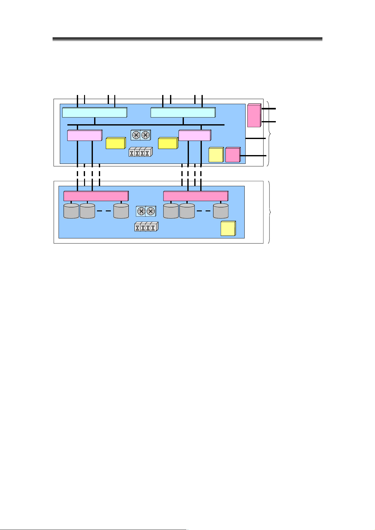
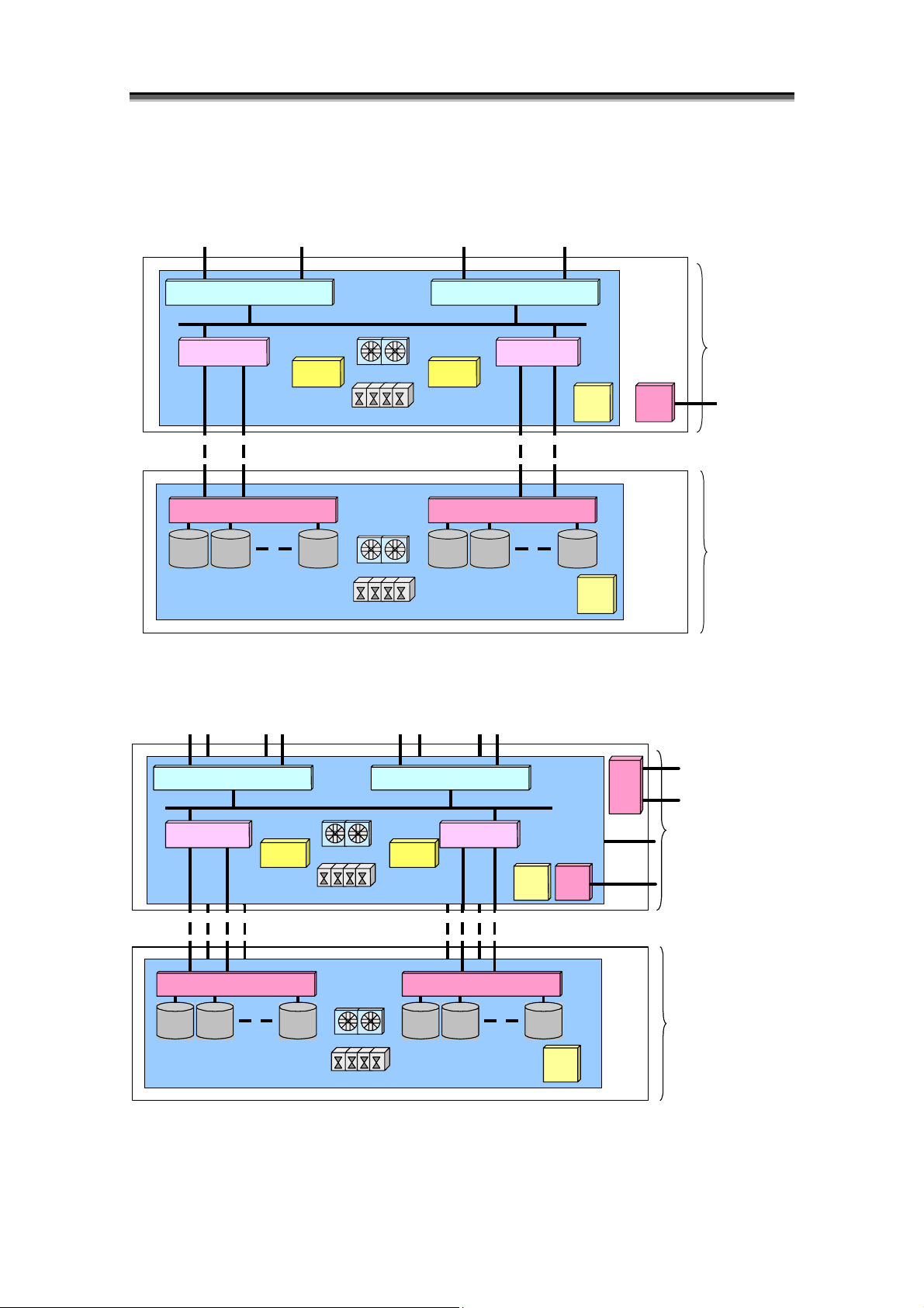
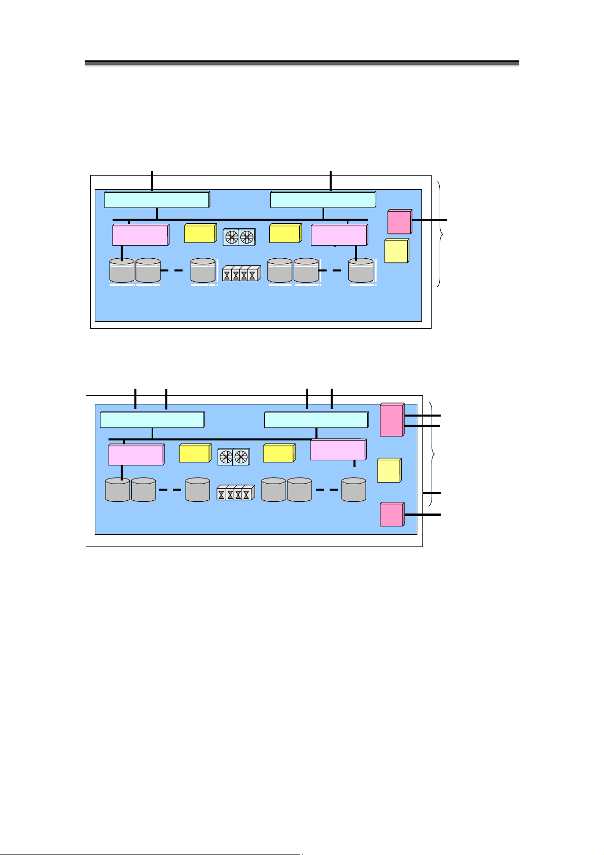
(1) Components
D
D
The disk array is composed of Disk Array Controller (DAC), which carries the component of
control systems, such as host director, disk director and cache, and Disk Enclosure (DE) that
carries two or more Physical Disks controlled by DAC.
i
s
k
i
s
k
A
A
A
r
r
a
y
C
o
n
f
i
g
u
r
a
t
i
o
n
r
r
a
y
C
o
n
f
i
g
u
r
a
r
r
a
y
C
o
n
f
i
g
u
t
r
a
t
i
o
n
i
o
n
Array Group 0
Array Group 2
Array Group 1
(up to 10 cabinets)
Figure 1-1 Disk Array Composition (4000 Series)
I-4
Page 13
Chapter 1 Storage Overview
)
Array Group 0
Array Group 2
Array Group 1
(up to 2 cabinets)
Figure 1-2 Disk Array Composition (3000 Series)
Figure 1-3 Disk Array Composition (2000/2800 Series)
Disk Enclosure (DE)
Disk Array Controller (DAC)
Physical Disk(PD
Figure 1-4 Disk Array Composition (100/1000 Series)
I-5
Page 14

Chapter 1 Storage Overview
<Components identification>
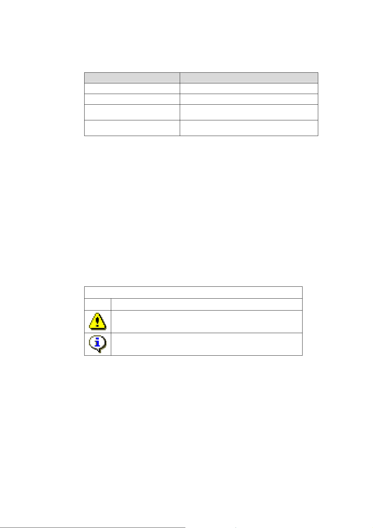
In the 3000/4000 series disk array, the cabinet composed of Disk Array Controller and two or more disk
enclosures is called as “Basic Cabinet (BC)” and the cabinet that is composed of multiple disk
enclosures to be connected to basic cabinet is called as “Extended Cabinet (EC)”. The 3000/4000
series disk array can mount 10 or 15 Physical Disks (PDs) per disk enclosure, and 4 disk enclosures are
managed as 1 group (array group). Individual PD has identification number per PD management
group (PD group) that includes the above 4 array groups. Thus the combination of PD group number
and PD position number enables identifying of the physical mounting place of the PDs.
In the same way, unique identification number is assigned to other components in disk enclosure
(shown below), per controller unit, and this identification number enables components in the same disk
enclosure to be specified. But assignment of identification number depends on number of component in
disk enclosure.
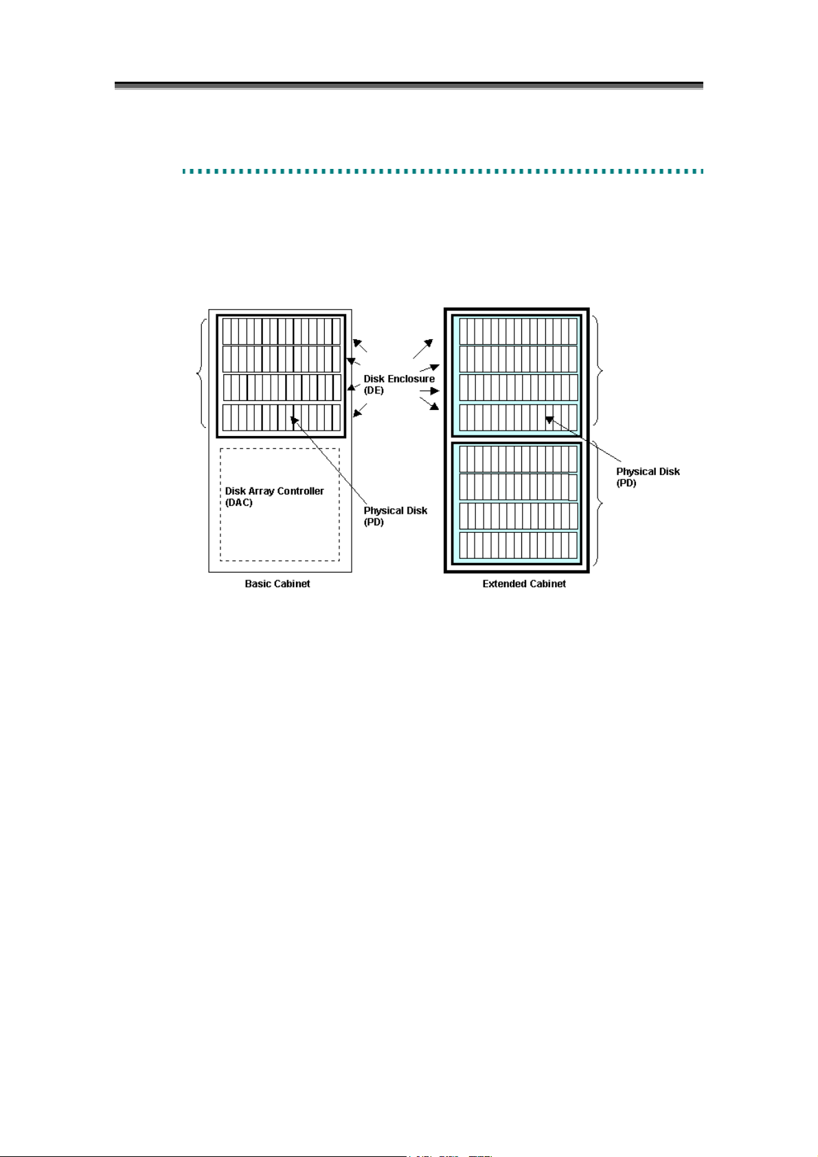
The 2800 series disk array is composed of Disk Array Controller (DAC) and one or more disk
enclosures. (There has no concept of basic cabinet and extended cabinet as in the 4000 series). It
can mount 15 physical disks (PDs) per disk enclosure. Only one PD management group (PD group) is
defined in it (i.e., all physical disks belong to one PD group). There is no concept of array group.
The 2000 series disk array is composed of Disk Array Controller (DAC) and one or more disk
enclosures. (There has no concept of basic cabinet and extended cabinet as in the 4000 series). It
can mount 10 or 15 Physical Disks (PDs) per disk enclosure. PD management group (PD group) is
defined depending on the connection relation to disk array controller. (PDs connected to the same
group are defined as one PD group) There is no concept of array group.
In the 100/1000 series disk array, Disk Array Controller (DAC) and DE which are in different cabinets
in the 2000 series are put in the same cabinet. 15 Physical Disks (PDs) can be carried in Disk Array
Controller (DAC). Because there is not the concept of array group, the Physical Disks connected to
the same group are managed as one group (PD group).
I-6
Page 15
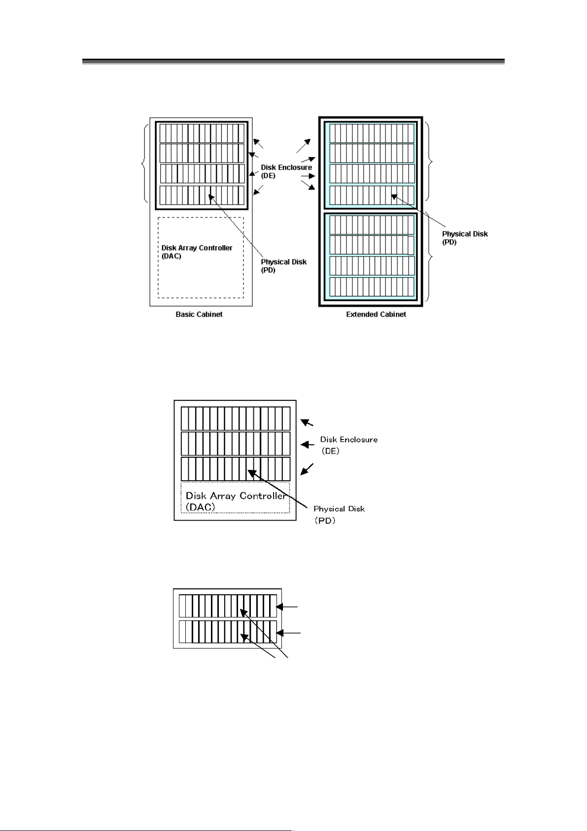
<4000 series>
Cach
Cach
FC Port FC Port
HD HD
HD RD
Back Board
RD
Cache
Module
Cache
Module
DD DD
Battery
DD
Junction Box
Fan
Power Supply
Junction Box
Battery
DD DD
Adapter Card Adapter Card
PD PD PD
Fan
PD PD
PD
Back Board
Power Supply
Junction Box Junction Box
<3000 series>
FC Port FC Port
HD
RD
e
Module
Back Board
e
Module
DD
DD
Battery
DD
Junction Box Junction Box
Fan
Power Supply
Battery
DD DD
Adapter Card Adapter Card
PD PD PD PD PD PD
Back Board
Junction Box Junction Box
Fan
Power Supply
Figure 1-5 3000/4000 Series Disk Array Components
HD
RD
Chapter 1 Storage Overview
HD HD
TEMP
ALM
Panel
DD
HD
Panel
DD
SVP
SVP
SVP
SVP
ETHER Port for
Monitoring
Disk Array
Controller (DAC)
ETHER Port
for Monitoring
Disk
Enclosure
ETHER Port
for Monitoring
Disk Array
Controller (DAC)
ETHER Port for
Monitoring
Disk Enclosure
I-7
Page 16
Chapter 1 Storage Overview
<2800 series>
FC Port FC Port
HD (HostDirector)
Cache Module
PD
Back Board
AdapterCard
Battery
PD
HD (HostDirector)
Cache Module
Fan
Power Supply
Battery
TEMP
ALM
AdapterCard
PDPD
Fan
Power Supply
PD PD
TEMP
ALM
Figure 1-6 2800 Series Disk Array Components
SVP
SVP
PCC
UPS Port
Disk Array
Controller (DAC)
Ether Port for
Monitoring
Disk Enclosure
I-8
Page 17
<2000 series>
- S2100/S2200/S2300
FC Port FC Port
HD (Host Director)
Cache Module
Adapter Card
PD
Back Board
- S2400
FC Port
Battery
Fan
Power Supply
Fan
Power Supply
FC Port
Chapter 1 Storage Overview
HD (Host Director)
Cache Module
Battery
Adapter Card
PD PD PD PD PD
TEMP
ALM
TEMP
ALM
SVP
Disk Array
Controller (DAC)
Ether Port for
Monitoring
Disk Enclosure
HD (HostDirector) HD (HostDirector)
Cache Module
Battery Battery
AdapterCard
PD
Back Board
Fan
Power Supply
Fan
Power Supply
Figure 1-7 2000 Series Disk Array Components
Cache Module
TEMP
ALM
AdapterCard
PDPD PD PD PD
I-9
SVP
SVP
TEMP
ALM
PCC
UPS Port
Disk Array
Controller (DAC)
Ether Port for
Monitoring
Disk Enclosure
Page 18
Chapter 1 Storage Overview
<100/1000 series>
- S100/S1100/S1200/S1300
(Host Director) HD(HostDirector)
HD
Cache Module
PD
Back Board
- S400/S1400
HD (HostDirector)
Cache Module
FC Port
FC Port
Battery
PD
Battery
Fan
Power Supply
Fan
FC Port
Battery
PDPD
Battery
Cache Module
PD
FC Port
HD (HostDirector)
Cache Module
PD
SVP
TEMP
ALM
PPC
TEMP
ALM
ETHER Port for
Monitoring
Disk Array
Controller (DAC)
UPS Port
Disk Array
Controller (DAC)
PD
Back Board
PDPD PD PD PD
Power Supply
SVP
SVP
Ether Port for
Monitoring
Figure 1-8 100/1000 Series Disk Array Components
I-10
Page 19
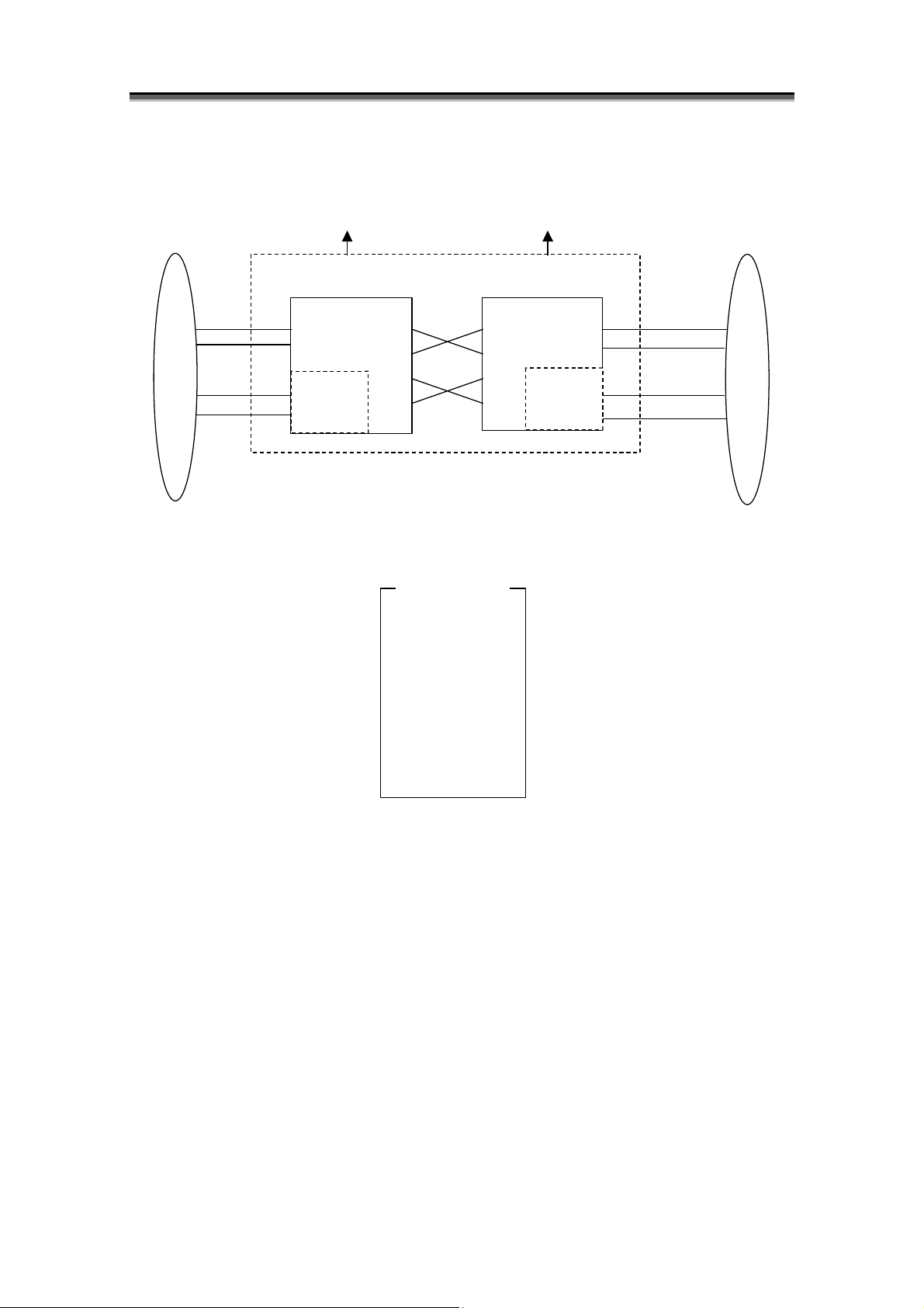
[2800 series logical block diagram (with alternative paths and options)]
FC Port
Chapter 1 Storage Overview
FC Port
Controller Block
Controller 0
Option
PD Group 0
Alternative Paths
Controller 1
Option
PD Group 0’
PD group 0
DE#0[00 - 0E]
DE#1[10 - 1E]
:
:
:
DE#E[E0 - EE]
DE#F[F0 - FE]
*1 The 2800 series disk array has one PD group.
*2 Hexadecimal digits in the brackets are PD numbers.
*3 DE denotes a disk enclosure.
*4 PD group 0 and PD group 0’ are the same PD group.
Figure 1-9 2800 Series Logical Block Diagram
I-11
Page 20
Chapter 1 Storage Overview
p
p
p
p
[2000 series logical block diagram]
- S2100/S2200/S2300 (with alternative paths and options)
0
Controller Block
FC Port
Alternative Paths
Controller 0
FC Port
Controller 1
0'
Option
Option
PD Grou
1
PD Grou
PD group 0
DE#0[00 – 0E]
DE#1[10 – 1E]
DE#2[20 – 2E]
DE#3[30 – 3E]
DE#4[40 – 4E]
DE#5[50 – 5E]
DE#6[60 – 6E]
*1 The 2000 series disk array has two PD groups.
*2 Hexadecimal digits in the brackets are PD numbers.
*3 “DE” denotes a disk enclosure.
*4 PD groups 0 and 0’ are the same PD group, and also PD groups 1 and 1’ are the same PD group.
Figure 1-10 2000 Series (S2100/S2200/S2300) Logical Block Diagram
DE#10[00 – 0E]
DE#11[10 – 1E]
DE#12[20 – 2E]
DE#13[30 – 3E]
DE#14[40 – 4E]
DE#15[50 – 5E]
DE#16[60 – 6E]
Option
PD group 1
PD Grou
1'
PD Grou
I-12
Page 21
[2000 series logical block diagram]
p
r
p
- S2400 (with alternative paths)
Controller Block
Controller 0
0
PD Grou
*1 S2400 has only one PD group.
*2 Hexadecimal digits in the brackets are PD numbers.
*3 “DE” denotes a disk enclosure.
*4 PD groups 0 and 0’ are the same PD group.
Figure 1-11 2000 Series (S2400) Logical Block Diagram
FC Port
Alternative Paths
DE#C[C0 – CE]
DE#D[D0 – DE]
PD group 0
DE#0[00 – 0E]
DE#1[10 – 1E]
DE#4[40 – 4E]
DE#5[50 – 5E]
DE#8[80 – 8E]
DE#9[90 – 9E]
Chapter 1 Storage Overview
FC Port
Controller 1
0'
ou
PD G
I-13
Page 22
Chapter 1 Storage Overview
p
p
[100/1000 series logical block diagram (with alternative paths)]
- S100/S1100/S1200/S1300 (with alternative paths)
0
PD Grou
*1 S100/S1100/S1200/S1300 disk array has only one PD group.
*2 Hexadecimal digits in the brackets are PD numbers.
*3 “DE” denotes a disk enclosure.
*4 PD group 0 and PD group 0’ are the same PD group.
Controller Block
Figure 1-12 100/1000 Series (S100/S1100/S1200/S1300) Logical Block Diagram
FC Port
Alternative Paths
Controller 0
PD group 0
DE#0[00 – 0E]
DE#1[10 – 1E]
FC Port
Controller 1
0'
PD Grou
I-14
Page 23
[100/1000 series logical block diagram (with alternative paths)]
p
PD Group 0
- S400/S1400 (with alternative paths)
*1 S400/S1400 disk array has only one PD group.
*2 Hexadecimal digits in the brackets are PD numbers.
*3 “DE” denotes a disk enclosure.
*4 PD group 0 and PD group 0’ are the same PD group.
*5 S400 cannot be connected to DE#C.
Controller Block
Controller 0
PD group 0
DE#0[00 – 0E]
DE#4[40 – 4E]
DE#8[80 – 8E]
DE#C[C0 – CE]
Figure 1-13 100/1000 Series (S400/S1400) Logical Block Diagram
Chapter 1 Storage Overview
Controller 1
0'
PD Grou
I-15
Page 24
Chapter 1 Storage Overview
<Components>
Disk array components are shown below.
Component (Abbreviation)
Disk Array Controller
(DAC)
Host Director (HD)
Replication Director (RD)
Disk Director (DD)
Cache Module Card (CHE) Cache memory
Service Processor Card (SVP)
Temperature Alarm
(DAC_TEMP_ALM)
Panel
(PANEL)
Fan
(DAC_FANU/FANL)
Power Supply
(DAC_PS)
Battery Backup Unit
(DAC_BBU)
Basic Cabinet Junction Box
(BC_JB)
Back Board
(DAC_BB)
Power Control Card (PCC) Power control part.
Table 1-1 Component List (1/2)
Configuration Devices
(Abbreviation)
Description
Host interface control and cache module
control device. One to four ports are
mounted in single director.
Control part of DynamicDataReplication and
RemoteDataReplication function. Two ports
are mounted in single director.
Disk array control device. Four ports are
mounted in single director.
Processing part that provides various interfaces
(maintenance PC, Ether, modem, SCBI) to
perform power supply control and
maintenance.
Temperature abnormality detection part with
temperature sensor, in DAC (Disk Array
Controller).
External panel composed of status display part
of disk array, and system power on/off
switches.
Cooling fan to maintain the constant
temperature inside of the controller. There
are two types: Upper and Lower.
Power supply part in DAC.
Power supply part to hold data of cache
module in DAC.
Connection part of AC power cable in the
basic cabinet. It supplies electric power for
components (configuration devices) of cabinet.
Back board connecting each component
(configuration devices) in DAC.
I-16
Page 25
Chapter 1 Storage Overview
Table 1-1 Component List (2/2)
Component (Abbreviation)
Disk Enclosure
(DE)
Pool
Physical Disk (PD) Physical Disk
Logical Disk (LD)
Configuration Devices
(Abbreviation)
Power Supply
(DE_PS)
Fan
(DE_FAN)
Adapter Card
(DE_ADP)
Extended Cabinet Junction Box
(EC_JB)
Temperature Alarm
(DE_TEMP_ALM)
Back Board
(DE_BB)
Description
Power supply part in DE (Disk Enclosure).
Cooling fan in DE to maintain the constant
temperature inside of the unit.
Adapter Card for connection between PD
and DD.
Connection part of AC power cable in the
extended cabinet. It supplies electric
power to components (configuration
devices) of cabinet.
Temperature abnormality detection part
with temperature sensor in DE.
Back board connecting each component
(configuration devices) in DE.
Virtual medium composing RAID by
putting multiple physical disks together.
Logical Disk (disk from operation host
side)
I-17
Page 26

Chapter 1 Storage Overview
(2) Logical configuration of a disk array
In a disk array, put multiple physical disks together to set up a virtual medium to compose RAID,
and partition the space in the virtual medium to make logical disks. Data on the logical disks is
stored into the areas of physical disk associated with the partitions on the virtual medium in which
the logical disks are composed.
The virtual medium is called a pool or RANK, and it supports different logical disk configurations
depending on the disk array.
• Pool
Disk arrays with pool
*The disk arrays with pool are the following:
S400/S1400/S2400/S2800
In the disk array indicated above, multiple physical disks put together to make up a virtual
medium for RAID is called a pool. The logical disks usually belong to one pool, and the
required amount of space is assigned from the pool.
There are two types of pool available as described below. They function in different manners.
Basic pool
The basic pool is a virtual medium, which manages the space on the pool using a continuous
address space.
As you handle logical disks on RANK, assign the continuous space on the pool to the logical
disks. In addition, like a multi-RANK configuration, the basic pool supports a striping
configuration for distributing and storing data into multiple RAID configurations.
For the practical configurations of physical disks that bind a basic pool, refer to C.3 “List of
Pool-Configurable RAID Types”.
Note that the basic pool does not allow using any additional features such as pool capacity
expansion or logical disk capacity expansion.
I-18
Page 27
Chapter 1 Storage Overview
Dynamic pool
The dynamic pool is a virtual medium, which manages the space on the pool using a virtual
storage space.
Like block management in a file system, the dynamic pool manages used space and unused
space. When making up logical disks, separate unused space from the pool according to the
required capacity, then assign the physical disk space corresponding to the logical disk space.
The dynamic pool moderates the limit on the number of constituent physical disks and enables
flexible configurations. In addition, the dynamic pool allows to use additional features such as
pool capacity expansion and logical disk capacity expansion. For details on the dynamic pool,
refer to 2.1.2 “Dynamic Pool”.
For the practical configurations of physical disks on a dynamic pool, refer to C.3 “List of
Pool-Configurable RAID Types”.
Logical Disk Configuration of Basic Pool
Basic Pool
PD00
Basic Pool
PD00
Dynamic Pool
PD00 PD01 PD02 PD03 PD04
PD01 PD02 PD03 PD04
Logical Disk Configuration of Basic Pool (Striping)
PD01 PD02 PD03 PD04
Logical Disk Configuration of Dynamic Pool
LD00
LD01
Figure 1-14 Logical Configurations of Disk Arrays (Pool)
LD03
LD02
LD00
LD01
LD02
LD03
...
...
LD00
LD01
LD02
LD03
PDnn
I-19
Page 28
Chapter 1 Storage Overview
• RANK
<Supported disk arrays>
Other than disk arrays with pool
In the disk arrays indicated above, multiple physical disks put together to make up a virtual
medium for RAID is called RANK. Areas on RANK are controlled by using a continuous
address space.
The logical disks usually belong to one RANK, and a continuous space on one RANK is
assigned to them.
In a multi-RANK configuration, the logical disks belong to multiple RANKs, and continuous
spaces on the multiple RANKs are assigned to them.
For the types of RAID configurable as RANK, refer to C.2 “List of RANK-Configurable RAID
Types”.
Logical Disk Configuration of RANK
RANK
PD00 PD01 PD02 PD03 PD04
RANK RANKn
PD00
Logical Disk Configuration of RANK (Striping)
PD01 PD02 PD03 PD04
Figure 1-15 Logical Configurations of Disk Arrays (RANK)
LD00
LD01
LD02
LD03
...
LD00
LD01
LD02
LD03
I-20
Page 29
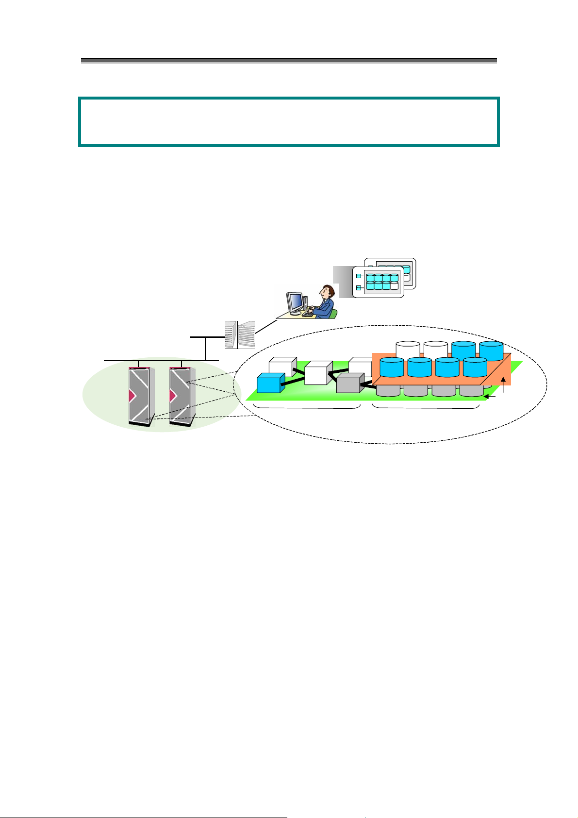
Chapter 2 Overview of Disk Array Configuration Setting
A
r
r
(
)
Chapter 2 Overview of Disk Array
Configuration Setting
This chapter describes an overview of the disk array configuration setting.
The disk array configuration setting is a function for setting the configuration when initializing the disk array and
when extending the physical disks. This operation can be performed by using a GUI from the iSM client.
dministrato
Storage Manage
Disk Array
Controller
Disk Array
Figure 2-1 Configuration Setting Outline
Configuration Display Screen
Logical Disk
DAC
Disk Enclosure (DE)
Physical
Disk
I-21
Page 30

Chapter 2 Overview of Disk Array Configuration Setting
2
.
1
P
o
o
l
a
n
d
R
A
N
K
2
.
1
P
o
o
l
a
n
d
R
2
.
1
P
o
o
l
a
n
d
In a disk array, put multiple physical disks together to set up a virtual medium to compose RAID, and
partition the space in the virtual medium to make logical disks. Data on the logical disks is stored into
the areas of physical disk associated with the partitions on the virtual medium in which the logical disks
are composed.
The virtual medium is called a pool or RANK, and it supports different logical disk configurations
depending on the disk array.
• Pool
<Supported disk array>
S400/S1400/S2400/S2800
In the disk array indicated above, multiple physical disks put together to make up a virtual medium
for RAID is called a pool. The logical disks usually belong to one pool, and the required amount of
space is assigned from the pool.
• RANK
<Supported disk arrays>
Other than S400/S1400/S2400/S2800
In the disk arrays indicated above, multiple physical disks put together to make up a virtual medium
for RAID is called RANK. Areas on RANK are controlled by using a continuous address space.
There are two types of pool available as described below. They function in different manners.
R
A
A
N
N
K
K
I-22
Page 31

Chapter 2 Overview of Disk Array Configuration Setting
2
.
1
.
1
B
a
s
i
c
P
o
o
l
2
.
1
.
1
B
a
s
i
c
2
.
1
.
1
B
a
The basic pool is a virtual medium, which manages the space on the pool using a continuous address
space.
As you handle logical disks on RANK, assign the continuous space on the pool to the logical disks. In
addition, like a multi-RANK configuration, the basic pool supports a striping configuration for
distributing and storing data into multiple RAID configurations.
Note that the basic pool does not allow using any additional features such as pool capacity expansion or
logical disk capacity expansion.
Logical Disk Configuration of Basic Pool
Basic Pool
PD00 PD01 PD02 PD03 PD04
Basic Pool
PD00 PD01 PD02 PD03 PD04
The table below shows the number of physical disks and the number of pools available by the RAID
type on S400/S1400/S2400/S2800.
- Basic pool
RAID Type
RAID1
RAID5 - -
RAID10 -
RAID50
Logical Disk Configuration of Basic Pool (Striping)
P
s
i
c
P
Figure 2-2 Logical Configuration of Disk Arrays (Basic Pool)
Disk Array
S400/S1400/
S2400/S2800
o
o
o
l
o
l
Number of Physical Disks
2 4 5 8 10 16 20
{
- - - - - -
{
{
- - - -
- - - -
{
-
-
{
...
{
-
LD00
LD01
LD02
LD03
-
{
LD00
LD01
LD02
LD03
{: Available -: Unavailable
I-23
Page 32

Chapter 2 Overview of Disk Array Configuration Setting
2
.
1
.
2
D
y
n
a
m
i
c
P
o
o
l
2
.
1
.
2
D
y
n
a
m
i
c
2
.
1
.
2
D
y
n
a
m
The dynamic pool is a virtual medium, which manages the space on the pool using a virtual storage
space.
Like block management in a file system, the dynamic pool manages used space and unused space.
When making up logical disks, separate unused space from the pool according to the required capacity,
then assign the physical disk space corresponding to the logical disk space.
The dynamic pool moderates the limit on the number of constituent physical disks and enables flexible
configurations. In addition, the dynamic pool allows to use additional features such as pool capacity
expansion and logical disk capacity expansion.
Logical Disk Configuration of Dynamic Pool
Dynamic Pool
PD00 PD01 PD02 PD03 PD04
Figure 2-3 Logical Configuration of Disk Arrays (Dynamic Pool)
S400/S1400/S2400/S2800 disk array supports the dynamic pool function.
The dynamic pool function puts a set of physical disks on the disk array together to make up a virtual
storage pool. That is, it picks up the amount of storage required for the transaction from space unused
in the pool and bind logical disks. If the storage capacity becomes short, you can add physical disks
one by one as required and putting them into the pool to expand the unused space of the pool. The
additional unused space of the pool can be used to bind a new logical disk or expand the existing logical
disk capacity, keeping the current data. In addition, you can put back logical disks no longer needed
to the pool to extend the unused space of the pool.
Therefore, the dynamic pool function helps to manage the capacity of the storage efficiently and make a
large reduction in the cost on additional storage space. It also helps to flexibly support any
configuration changes or expansion of the storage to be done for addition of new transactions or
modification to existing transactions.
LD00
LD01
P
i
c
P
o
o
o
o
l
l
LD03
LD02
...
PDnn
I-24
Page 33

p
p
Add physical disks one by one as
required to the pool to expand the
available s
ace.
Physical Disk
Pool
Disk Array
The dynamic pool function provides the following advantages:
• Reduction in the cost of storage expansion
When some additional storage space is required due to an addition of new transactions and so forth,
you can add physical disks one by one as required to bind a new logical disk or expand the logical
disk capacity at that time. This means that you can add physical disks just enough for the required
capacity only with the least additional cost.
• Better flexibility of storage configuration
If the amount of data to be handled increases and the storage capacity becomes short, you can expand
the logical disk space, keeping the existing data in the logical disks. In addition, returning logical
disks no longer needed to the pool secures the unused space of the pool which can be used for another
purpose. With these features, you can flexibly support any configuration changes of storage to be
made for modification to existing transactions or operation of existing transactions.
Chapter 2 Overview of Disk Array Configuration Setting
Server
Create a new logical
Logical Disk
Put back a logical disk
no longer needed to
the
Figure 2-4 Overview of the Dynamic Pool Function
disk.
Expand the existing
logical disk capacity,
keeping the current
data.
ool.
I-25
Page 34

Chapter 2 Overview of Disk Array Configuration Setting
(1) You can bind a dynamic pool:
You can bind a virtual storage space, or a dynamic pool, by selecting a set of unused physical
disks on the disk array. The RAID type usable and the number of physical disks required for a
dynamic pool are fixed. Select either of the following two types of RAID6 configuration
according to the number of physical disks required. The two types of configuration have
different capacity efficiencies:
RAID6 (4+PQ): 6 or more physical disks required (capacity efficiency: 67% approx.)
RAID6 (8+PQ): 10 or more physical disks required (capacity efficiency: 80%)
For details on how to bind a dynamic pool, refer to 7.1.1 “Binding a Pool” in Part IV
“Operations”.
y Dynamic pool
RAID Type
RAID6 (4+PQ) 6 to 60
RAID6 (8+PQ)
Disk Array Number of Physical Disks
S400/S1400/
S2400/S2800
(120 or 240)*1
10 to 60
(120 or 240)*1
*1: The maximum number of physical disks is 60 when pools are in use.
To use 61 or more disks, you need to add physical disks by extending dynamic pools.
(2) You can expand the dynamic pool capacity:
You can expand the capacity of the dynamic pool by selecting unused physical disks on the disk
array and putting them into the dynamic pool. The capacity actually added is the capacity of the
additional physical disk(s) multiplexed by the pool capacity efficiency. You can add physical
disks one by one. Naturally, you can add multiple physical disks at one time.
Usually, expanding the dynamic pool rebuilds data on the additional physical disk(s) to keep the
redundancy of RAID. Rebuilding data puts some load to the physical disks of the dynamic pool
and influences access to the existing logical disks which belong to the pool. The additional
space becomes available after the rebuild process finishes.
However, when the number of physical disks simultaneously added to the pool is a specified
number or more, the dynamic pool is expanded and made available without the rebuild process.
The additional space is usable immediately after the physical disks are added to the pool.
The RAID configuration cannot be changed from RAID6 (4+PQ) to RAID6 (8+PQ) or vise versa.
You need to add physical disks to the pool, keeping the RAID configuration.
I-26
Page 35

Chapter 2 Overview of Disk Array Configuration Setting
For details on how to expand a dynamic pool, refer to 7.1.2 “Expanding Capacity of a Pool” in
Part IV “Operations”.
Additional
Physical Disks
1 to 5 RAID6 (4+PQ)
1 to 9 RAID6 (8+PQ)
6 or more RAID6 (4+PQ)
10 or more RAID6 (8+PQ)
(3) You can bind the logical disks:
You can pick up the amount of storage required from the unused space in the dynamic pool and
bind logical disks required for it. For details on how to bind logical disks, refer to 7.2.1
“Binding Logical Disks” in Part IV, “Operations”.
(4) You can expand the logical disk capacity:
Configuration Rebuild after Expansion of Pool
The pool is rebound. Rebinding the pool influences
access to the existing logical disks which belong to
the pool. The additional space to the pool becomes
available after the rebind process finishes.
The pool is not rebound. The expansion of the pool
puts no influence on any existing logical disks which
belongs to it. The additional space to the pool
becomes available immediately after it is added.
You can pick up the amount of storage required from the unused space in the dynamic pool and
increase the existing logical disk capacity. While data stored in the logical disks is secured,
some space usable for additional logical disks is added after the existing logical disks. The way
of having the host identify the additional space depends on the platform.
For details on how to expand the logical disk capacity, refer to 7.2.2 “Expanding Capacity of
Logical Disks” in Part IV “Operations”.
Some platforms do not support expansion of logical disk capacity. For details about it, ask the
maintenance personnel. In addition, in case of an error or failure, it is recommended to make a
backup of data stored in the existing logical disks before expanding the logical disk capacity.
I-27
Page 36

Chapter 2 Overview of Disk Array Configuration Setting
2
.
1
.
3
R
A
N
K
2
.
1
.
3
R
2
.
1
.
3
The logical disks usually belong to one RANK, and a continuous space on one RANK is assigned to
them.
In a multi-RANK configuration, the logical disks belong to multiple RANKs, and continuous spaces on
the multiple RANKs are assigned to them.
RANK
PD00 PD01 PD02 PD03 PD04
RANK RANKn
PD00 PD01 PD02 PD03 PD04
Number of Physical Disks
RAID
Type
RAID0
RAID1 -
RAID5 - -
RAID10
Logical Disk Configuration of RANK (Striping)
The table below shows the number of physical disks and the number of RANKs available by the RAID
type on the 100/1000/2000 series (not including S400/S1400/S2400).
Disk Array
100/1000/2000
series
A
R
A
Logical Disk Configuration of RANK
Figure 2-5 Logical Configurations of Disk Arrays (RANK)
N
K
N
K
LD00
LD01
LD02
LD03
...
1 2 3 4 5 6 7 8 9 10 11 12 13 14 15
{
- - - { -
{
-
{
- - - - - - - - - - - - -
{ { { { { { { { { { { { {
{
-
- - - -
{
{
-
{
- - - -
{
-
-
{
-
LD00
LD01
LD02
LD03
{
{
-
{: Available -: Unavailable
I-28
Page 37

Chapter 2 Overview of Disk Array Configuration Setting
g
p
)
2
.
2
L
o
g
i
c
a
l
D
i
s
k
2
.
2
L
o
g
i
c
a
l
2
.
2
L
o
g
i
c
The logical disks in the disk array are equivalent to the physical disk when viewed from the OS. In
the OS, this physical disk is partitioned to be managed as multiple logical disks. In the disk array,
multiple physical disks are bound as a pool or RANK, which is then divided to form logical disks.
Physical Disks
Multiple physical disks
are bound to form a
pool or RANK.
*1 When the OS is used to support the volume group and the software RAID, etc.
*2 The PD group refers to a management aggregate of physical disks consisting of one or more DEs.
*3 The Disk Enclosure (DE) refers to a management aggregate of 10 to 15 physical disks.
*4 The physical disk number and the RANK number are given in terms of each PD group.
Disk Array
Pool
or
RANK
PD Group *2
Figure 2-6 Physical Disks and Logical Disks
D
a
l
D
Logical Disks
The pool or RANK is
divided to form
Disk Enclosure (DE
i
s
k
i
s
k
OS
ical Disks
Physical Disks
Sam
Multiple physical disks are
used to form logical disks.
PD Grou
*3
Lo
The physical disk is
divided to form logical
disks.
Physical Disk Number *4
*1
I-29
Page 38

Chapter 2 Overview of Disk Array Configuration Setting
2
.
3
S
p
a
r
e
2
.
3
S
2
.
3
When binding pools or RANKs other than RAID0, data are still in the disks even when a single
physical disk (two physical disks for RAID6) fail(s). However, if one more physical disk fails, data
may be in danger of being lost.
To cope with this situation, the reliability of the disk array can be enhanced further by switching to a
reserve (i.e. Spare) disk which is set beforehand, at the point when a physical disk fails.
Spares can be set for physical disks which are not used in pool or RANK binding, thus making it
possible to recover data to a Spare in the same PD group when a physical disk fails. When recovery to
Spares is started, the pool or RANK is rebuilt and the Spares become physical disks which comprise the
pool or RANK. The failed physical disk can be replaced without stopping the access to the disk array.
Considering the physical layout, it is normally desirable to set one spare disk per DE for the physical
disk in the rightmost slot in the DE.
S
p
p
a
a
r
e
r
e
2
.
4
N
i
c
k
n
a
m
e
2
.
4
N
i
c
k
n
2
.
4
N
i
c
Nicknames refer to any names that can be set for the disk array, the logical disk, the port, and the pool
with regard to iSM’s management target. Since the names thus set are stored in the disk array, they
are held regardless of whether iSM or a disk array is restarted or not.
(1) Disk Array Name
Refers to any ID name for iSM’s management target disk array. When the disk array is
specified with iSM, the disk array name is used.
(2) LD Name
Refers to any ID name for a logical disk in iSM’s management target disk array. When the
logical disk is specified with iSM, the LD name is used.
(3) Port Name
Refers to any ID name for a port in iSM’s management target disk array. When the port is
specified with iSM, the port name is used.
(4) Pool Name
Refers to any ID name for a pool in the iSM’s management target disk array. When the pool is
specified with iSM, the pool name is used.
k
n
a
a
m
m
e
e
I-30
Page 39

Chapter 2 Overview of Disk Array Configuration Setting
Before operating the disk array, users can perform efficient management of the disk array by setting the
ID information with the nickname.
I-31
Page 40

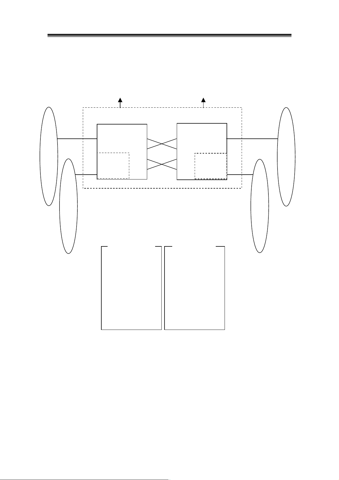
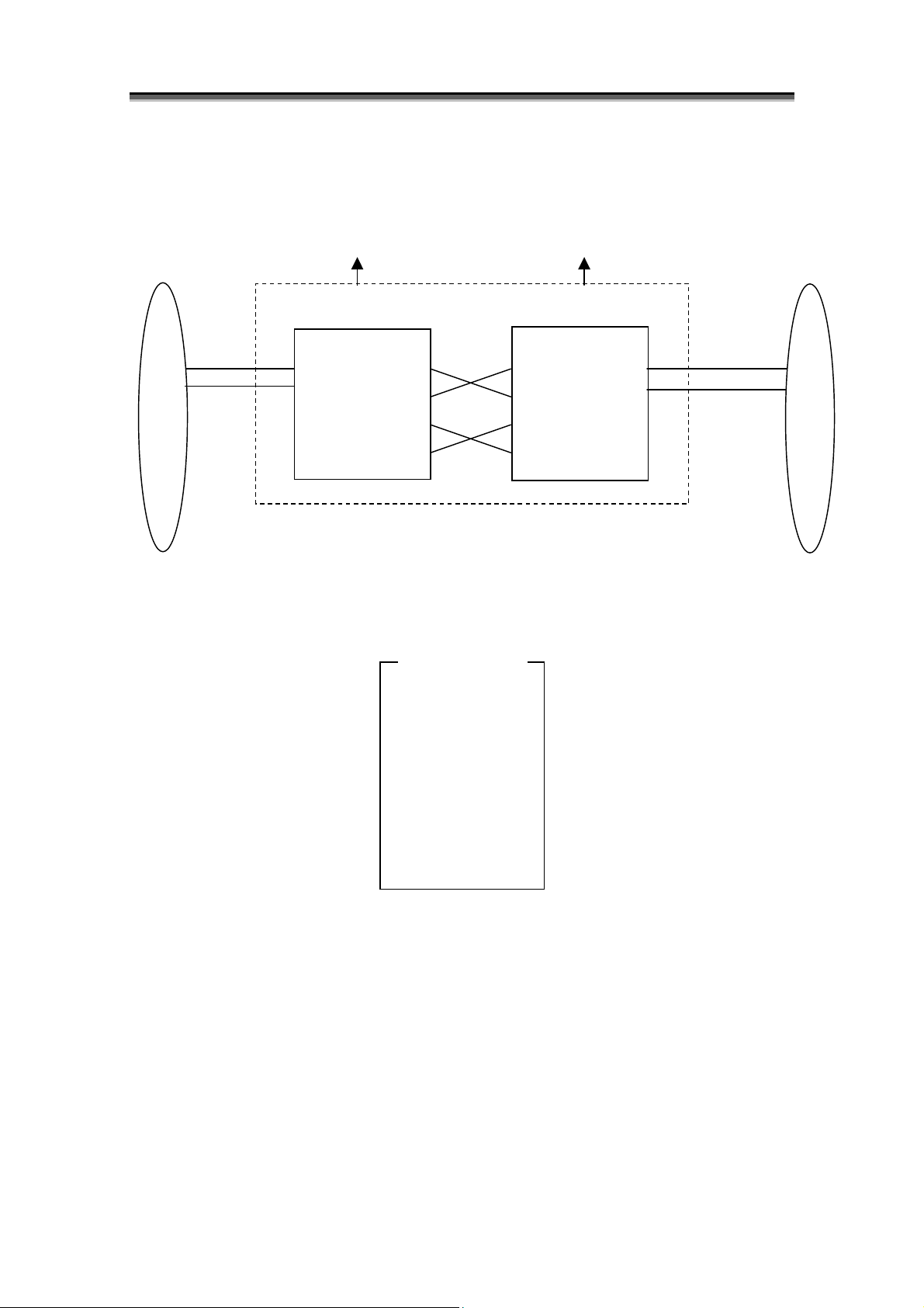
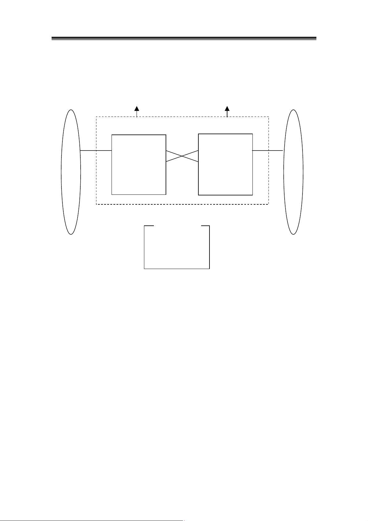
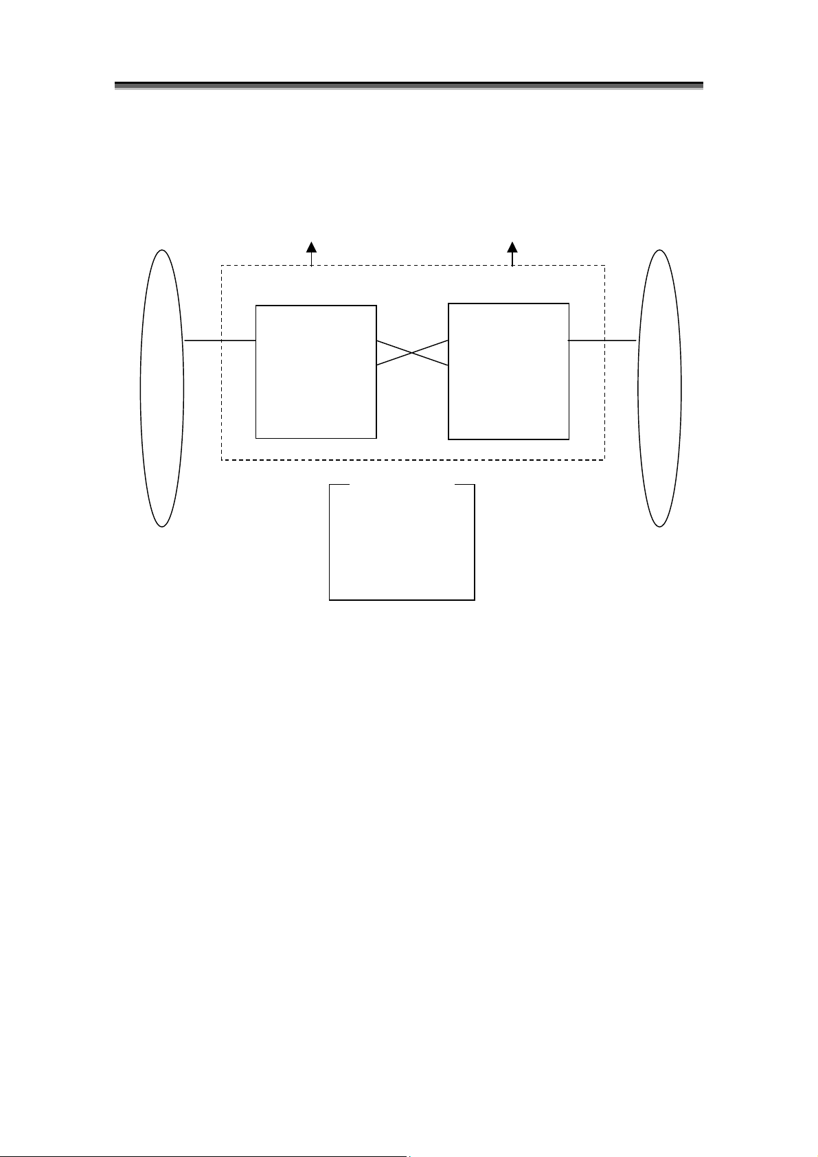
Chapter 3 Overview of AccessControl
ay
A
r
r
A
A
Chapter 3 Overview of AccessControl
This section describes functions available when program product “AccessControl” is purchased. The
AccessControl is optional software.
The AccessControl provides functions to set and unset information on accessibility from the business server to
logical disks.
Using these functions enables users to easily and flexibly change configuration of logical disks and perform
accessibility setting.
Disk Arr
In Use from Business Serve
LD Set LD Set
In Non-use from Business Serve
ccessControl
function protects
LDs from
business server
Figure 3-1 Overview of Access Control
y [Inaccessible area]
Logical disk groups hidden from the business server by using the AccessControl function exist in this area.
This area is called Preserve Group.
[Preserve Group] Logical disks hidden from the business server and inaccessible exist in this area. Contents of
the logical disks are retained and existing logical disks include logical disks with no special purpose settings,
logical disks set in pairs for replication (MV, RV), volume for snapshots (BV), and link-volume (LV).
y [Accessible area]
Logical disk groups accessible from the business server by using the AccessControl function exist in this area.
Contents of the logical disks depend on the business server, and existing logical disks include ordinary logical
disks with no special purpose settings, replication volume (MV, RV), volume for snapshots (BV), and
link-volume (LV). In addition, each logical disk is assigned to an LD Set.
ccessible Area
Inaccessible Area
[Preserve Group]
dd/Delete of
logical disks
is possible.
I-32
Page 41

Chapter 3 Overview of AccessControl
3
.
1
L
D
S
e
t
3
.
1
L
D
3
.
1
The concept of “LD Set” is introduced to Access Control. The concept of LD Set enables to assign
logical disks collectively to ports of multiple disk arrays and WWNs. When one single business
server has multiple access paths and if its I/O paths are duplicated or it is clustered, define multiple
access paths together by using an LD Set.
For ports and WWNs defined as paths of an identical LD Set, Access Control can be collectively set.
That is, when you add or remove an LD Set after setting up Access Control, you can collectively handle
ports and WWNs with an LD Set specified.
When a disk array with the program product AccessControl(WWN) applied is in use, only WWNs can
be defined as paths of LD Sets.
L
D
S
S
e
e
t
t
I-33
Page 42

Chapter 3 Overview of AccessControl
Business Server A Business Server B Business Server C
HBA0 HBA1
WWN (WWPN)
Link between Path Information and LD Sets
Port0 Port1 Port2 Port3
LD00
LD06
LD01
LD07
LD Set LD Set LD Set
WWN Mode Port Mode
HBA2 HBA3
WWN (WWPN)
LD02
LD08
LD03
LD09
HBA4
Port Number
LD04
LD0a
LD05
LD0b
Figure 3-2 Schematic Diagram of AccessControl
I-34
Page 43

Chapter 3 Overview of AccessControl
3
.
2
W
W
N
M
o
d
e
3
.
2
W
W
N
M
3
.
2
W
W
N
(1) Function
This function, which can set the accessible logical disk in terms of each business server HBA
(Host Bus Adaptor), can set whether the logical disk is accessible or not in terms of each server.
The HBA has the only ID code called WWN (World Wide Name). Use this code to set the
WWN which allows access to logical disks.
M
o
o
d
d
e
e
I-35
Page 44

Chapter 3 Overview of AccessControl
Business Server A
HBA0 HBA1 HBA2 HBA3 HBA4
Accessible from
HBA
Port0 Port1
LD00
LD01 LD07
Server A
Figure 3-3 Schematic Diagram of AccessControl (WWN Mode)
Table 3-1 Setting WWN and Logical Disk Numbers
Logical Disk
0 √ √ - - - - √ √ - - - -
1 √ √ - - - - √ √ - - - -
2 - - √ √ - - - - √ √ - -
3 - - √ √ - - - - √ √ - -
4 - - - - √ - - - - - √ -
Switch Switch
LD06 LD02
No.
00 01 02 03 04 05 06 07 08 09 0a 0b
Business Server B
LD03 LD04
LD08 LD09
Accessible from
Server B
Port2
Business Server C
Port3
LD0a
Accessible
from Server C
LD05
LD0b
Inaccessible from Any
Business Server
√: Sets HBA’s WWN and logical disk number as being accessible.
-: Sets HBA’s WWN and logical disk number as being inaccessible.
According to the settings above:
• Business server A can access logical disks LD00, LD01, LD06, and LD07.
• Business server B can access logical disks LD02, LD03, LD08, and LD09.
I-36
Page 45

Chapter 3 Overview of AccessControl
• Business server C can access logical disks LD04 and LD0a.
• LD05 and LD0b cannot be accessed from any business server.
This function can divide the logical disks which bind the disk array into logical disk groups in
terms of each business server HBA (Host Bus Adaptor). It can also restrict the access in terms of
each server, thus making possible data protection and security protection, etc.
(2) Setting
This mode can be set through the configuration setting screen of the iSM client.
3
.
3
P
o
r
t
M
o
d
e
3
.
3
P
3
.
3
(1) Function
P
o
o
r
t
M
r
o
t
M
o
d
d
e
e
This function, which can set the accessible logical disk in terms of each disk array port, allows the
access management for the logical disk in terms of each business server connected to each port of
the disk array.
I-37
Page 46

Chapter 3 Overview of AccessControl
Business Server A
HBA0 HBA1
Port0 Port1 Port2 Port3
LD00
LD06
Accessible from Server A Accessible from Server B Accessible
LD01
LD07
Business Server B
HBA2 HBA3
LD02
LD08 LD09
LD03
Business Server C
LD04
LD0a LD0b
Inaccessible from
from Server
C
Any Business
Server
LD05
Figure 3-4 Schematic Diagram of Access Control (Port Mode)
Table 3-2 Setting Port and Logical Disk Numbers
Logical
Disk No.
Port
Port0 √ √ - - - - √ √ - - - -
Port1 √ √ - - - - √ √ - - - -
Port2 - - √ √ - - - - √ √ - -
Port3 - - - - √ - - - - - √ -
√: Sets the port and logical disk number as being accessible.
-: Sets the port and logical disk number as being inaccessible.
According to the settings in Table 3-2:
• Business server A can access logical disks LD00, LD01, LD06 and LD07 through ports Port0
and Port1.
• Business server B can access logical disks LD02, LD03, LD08 and LD09 through port Port2.
00 01 02 03 04 05 06 07 08 09 0a 0b
I-38
Page 47

Chapter 3 Overview of AccessControl
• Business server C can access logical disks LD04 and LD0a through port Port3.
• LD05 and LD0b cannot be accessed from any business server.
This function can divide the logical disks which bind the disk array into logical disk groups and
set whether to restrict the access or not in terms of each port. Data protection and security
protection, etc. in terms of each business server connected to the port can be achieved through this
function.
(2) Setting
This mode can be set through the configuration setting screen of the iSM client.
For setting of a disk array with the program product AccessControl(WWN) in port mode, ask our
maintenance personnel.
I-39
Page 48

Chapter 3 Overview of AccessControl
This page is intentionally left blank.
I-40
Page 49

P
P
P
a
a
a
r
r
r
t
I
I
I
n
s
t
a
l
l
a
t
i
o
t
I
I
I
n
s
t
a
l
l
t
I
I
I
n
s
t
a
a
l
l
a
n
t
i
o
n
t
i
o
n
Page 50

Chapter 4 Configuration Setting and Access Control Installation
Chapter 4 Configuration Setting and Access
Control Installation
4
.
1
S
y
s
t
e
m
C
o
n
f
i
g
u
r
a
t
i
o
n
4
.
1
S
y
s
t
e
m
C
o
n
f
i
g
u
r
a
4
.
1
S
y
s
t
e
m
C
o
n
f
i
g
u
For information on configuration settings and examples of system configuration when using Access Control function,
refer to Chapter 3 “System Configuration” of the “Manual Guide”.
4
.
2
C
o
n
f
i
g
u
r
a
t
i
o
n
4
.
2
C
o
n
f
i
g
u
r
a
t
4
.
2
C
o
n
f
i
g
u
A
c
c
e
s
s
A
c
c
c
c
e
e
A
Configuration Setting and Access Control functions are installed at the same time installing the iSM server. For
information on installing and uninstalling, refer to “Server Installation” and “Client Installation” in the “User’s
Manual” or “User’s Manual (UNIX)” in accordance with the OS in use.
s
s
s
s
C
C
C
i
r
a
t
i
o
n
o
n
o
n
o
o
t
t
t
r
r
r
n
n
o
o
o
l
S
S
S
l
l
t
r
a
t
e
t
t
i
e
t
t
i
e
t
t
i
I
n
s
t
I
n
s
t
I
n
s
t
i
i
n
n
n
a
o
o
a
a
g
g
g
l
l
l
n
n
l
l
a
n
d
a
a
a
t
a
l
a
n
d
n
d
i
o
n
t
t
i
o
n
i
o
n
II-2
Page 51

P
a
r
t
I
I
I
A
p
p
l
i
c
a
t
i
o
n
P
a
r
t
I
I
I
A
p
p
l
i
c
a
t
P
a
r
t
I
I
I
A
p
p
l
i
c
a
i
t
i
o
o
n
n
Page 52

Chapter 5 Operation Procedures
Chapter 5 Operation Procedures
5
.
1
I
n
i
t
i
a
l
I
n
s
t
a
l
l
a
t
i
o
n
5
.
1
5
.
1
When initially installing a system and a disk array, make the settings basically in accordance with the following
procedure.
I
n
i
t
i
a
l
I
n
s
t
a
l
l
a
I
n
i
t
i
a
l
I
n
Set the Storage Manger
Set a Disk Array
s
t
a
t
l
l
a
t
i
o
n
i
o
n
Execute the following work while referring to the “User’s
Manual” or “User’s Manual (UNIX)” in accordance with
your OS.
• Install the iSM.
• Set the target disk array as a monitoring target.
• Set the user information.
If necessary, set a Disk Array. (For details, refer to
5.1.2 “Setting a Disk Array”.)
Bind a pool or RANK. (For details, refer to 5.1.3
Bind a Pool or RANK
Bind a Logical Disk
Set a Logical Disk Nickname
Install the Access Control
“Binding a Pool or RANK”.)
Bind a logical disk. (For details, refer to 5.1.4 “Binding
a Logical Disk”.)
Set a nickname of the logical disk. (For details, refer to
5.1.5 “Setting a Logical Disk Nickname”.)
If necessary, newly install the Access Control. (For
details, refer to 5.1.6 “Installing the Access Control”.)
III-2
Page 53

Chapter 5 Operation Procedures
5
.
1
.
1
S
e
t
t
i
n
g
t
h
e
S
t
o
r
a
g
e
M
a
n
a
g
e
r
5
.
1
.
1
S
e
t
t
i
n
g
t
h
e
S
t
o
r
a
g
e
M
a
n
5
.
1
.
1
S
e
t
t
i
n
g
t
h
e
S
t
o
r
a
g
e
M
The following work is required before setting the configuration of the disk array.
(1) Installing the Storage Manger
For information on installing the iSM, refer to the “Installation and Setting” in the “User’s Manual” or “User’s
Manual (UNIX)” in accordance with your OS.
(2) Considering the target Disk Array as a monitoring target
It is necessary to consider the disk array as the monitoring target by iSM in setting the configuration of the disk
array. For information on how to target for monitoring, refer to 1.3 “Environmental Setting” in the “User’s
Manual” or “User’s Manual (UNIX)” in accordance with your OS.
(3) Setting the user information
For user information settings, refer to 1.3 “Environmental Setting” in the “User’s Manual” or “User’s Manual
(UNIX)” and 6.2 “Operating Range” in this manual. To set configuration, your user level needs to be Level 3.
To see configuration, your user level needs to be Level 1 or higher.
a
n
a
a
g
g
e
e
r
r
5
.
1
.
2
S
e
t
t
i
n
g
a
D
i
s
k
A
r
r
a
y
5
.
1
.
2
S
e
t
t
i
n
g
a
D
i
s
k
A
5
.
1
.
2
S
e
t
t
i
n
g
a
D
i
s
Depending on the operating environment, it is necessary to set the disk array. For information on the parameters,
refer to 6.1 “Parameters”. Before changing the settings, carefully read the disk array manual until they are fully
understood. For how to set the disk array, refer to Chapter 9 “Configuration Setting (Common to All Units)”.
5
.
1
.
3
B
i
n
d
i
n
g
a
P
5
.
1
.
3
B
i
n
d
i
n
g
5
.
1
.
3
B
i
n
d
Bind the pool or RANK. RAID configurations differ depending on the disk array.
- Disk arrays with pool
S400/S1400/S2400/S2800
- Disk arrays with RANK
Other than S400/S1400/S2400/S2800
For specific procedures, refer to 7.1 "Pool Binding" or 8.1 "Binding a RANK".
i
n
g
o
a
P
a
o
P
o
k
o
o
o
r
A
r
l
o
l
o
l
o
r
a
y
r
a
y
r
R
A
N
K
r
R
A
r
R
A
N
N
K
K
III-3
Page 54

Chapter 5 Operation Procedures
5
.
1
.
4
B
i
n
d
i
5
.
1
.
4
B
5
.
1
.
4
Bind a logical disk on a pool or RANK.
For specific procedure, refer to the following sections.
To bind a logical disk only (individual setting)
- Refer to 7.2.1 "Binding Logical Disks" for disk arrays with pool.
- Refer to 8.2.1 "Binding Logical Disks" for disk arrays with RANK
To bind a pool/RANK and logical disks (batch setting)
- Refer to 7.2.6 "Logical Disk Batch Setting" for disk arrays with pool.
- Refer to 8.2.4 "Logical Disk Batch Setting" for disk arrays with RANK.
Logical disks whose capacities are not the same cannot be paired. Therefore, to use data replication, bind logical
disks having the same capacity in advance.
5
.
1
.
5
5
5
.
1
.
5
.
1
.
5
B
S
S
S
i
e
e
e
i
n
n
n
d
i
n
d
i
t
t
i
n
t
t
i
n
t
t
i
n
n
g
g
g
g
g
g
a
L
o
g
i
c
a
l
D
i
s
k
a
L
o
g
i
c
a
l
a
L
o
g
i
a
L
o
g
i
a
L
a
L
o
o
g
g
c
i
c
i
c
c
a
a
a
a
D
l
D
l
D
i
l
D
l
D
i
s
k
i
s
k
s
k
N
i
c
k
n
a
m
e
i
s
k
N
i
c
k
n
i
s
k
N
i
c
k
n
a
a
m
m
e
e
You need to set the logical disk name to change the nickname allocated at logical disk binding.
For specific procedure, refer to the following sections.
- Refer to 9.1.4 "Renaming a Logical Disk" to set a nickname.
- Refer to 9.1.5 "Nickname Batch Setting" to set multiple nicknames
5
.
1
.
6
I
n
s
t
a
l
l
i
n
g
t
h
e
A
c
c
e
s
s
C
o
n
t
r
o
l
5
.
1
.
6
I
n
s
t
a
l
l
i
n
g
t
h
e
A
c
c
e
s
s
C
o
5
.
1
.
6
I
n
s
t
a
l
l
i
n
g
t
h
e
A
c
c
e
s
s
Install the Access Control. For specific procedures, refer to 5.4 "Access Control Installation".
n
C
o
n
t
r
o
l
t
r
o
l
III-4
Page 55

Chapter 5 Operation Procedures
5
.
2
P
h
y
s
i
c
a
l
D
i
s
k
E
x
p
a
n
s
i
o
n
5
.
2
5
.
2
When expanding physical disks to the disk array in operation, make the settings basically in accordance with the
following procedure.
5
.
2
.
5
.
2
.
5
.
2
.
1
1
P
h
y
s
P
h
Bind/Expand a Pool or RANK
Change the Access Control
B
1
B
B
i
i
y
s
i
Bind a Logical Disk
Configuration
n
d
i
n
n
d
d
n
i
n
i
i
i
c
n
c
g
g
g
a
a
l
D
i
s
k
E
x
p
a
n
d
d
d
a
s
n
s
i
n
g
i
n
g
i
n
g
l
D
i
s
k
E
x
p
In operating the program, bind/expand a pool or RANK.
(For details, refer to 5.2.1 “Binding and Expanding a Pool
or RANK”.)
In operating the program, if necessary, bind a logical disk.
(For details, refer to 5.2.2 “Binding a Logical Disk”.)
If necessary, change the Access Control configuration.
(For details, refer to 5.2.3 “Changing the Access Control
Configuration”.)
a
n
d
E
x
p
a
a
n
d
n
d
E
E
a
x
x
p
p
a
a
n
n
n
i
o
n
i
o
n
a
P
o
o
l
o
r
R
A
N
K
a
P
o
o
l
o
r
R
a
P
o
o
l
o
A
r
R
A
N
N
K
K
Build/expand a pool or RANK using the expanded physical disks.
For specific procedure, refer to the following sections.
For disk arrays with pool
- Refer to 7.1.1 "Binding a Pool" to build a new pool.
- Refer to 7.1.2 "Expanding Capacity of a Pool" to expand the existing pool.
For disk arrays with RANK
- Refer to 8.1.1 "RANK Bind" to build a new RANK.
- Refer to 8.1.3 "Expanding a RANK" to expand the existing RANK.
III-5
Page 56

Chapter 5 Operation Procedures
5
.
2
.
2
B
i
n
d
i
5
.
2
.
2
B
5
.
2
.
2
Bind/expand a logical disk on the pool or RANK that was newly added or expanded.
For specific procedure, refer to the following sections.
To bind a logical disk only (individual setting)
- Refer to 7.2.1 "Binding Logical Disks" for disk arrays with pool.
- Refer to 8.2.1 "Binding Logical Disks" for disk arrays with RANK.
To bind a pool/RANK and logical disks (batch setting)
- Refer to 7.2.6 "Logical Disk Batch Setting" for disk arrays with pool.
- Refer to 8.2.4 "Logical Disk Batch Setting" for disk arrays with RANK.
To expand a logical disk (individual setting)
- Refer to 7.2.2 "Expanding Capacity of Logical Disks" for disk arrays with pool.
Logical disks whose capacities are not the same cannot be paired. Therefore, to use data replication, bind logical
disks having the same capacity in advance.
5
.
2
.
3
5
5
.
2
.
3
.
2
.
3
B
C
C
C
i
i
h
h
h
n
n
a
a
a
d
d
n
n
n
n
i
n
i
g
g
n
g
g
g
g
i
i
i
n
n
n
a
L
o
g
i
c
a
l
D
i
s
k
s
s
s
i
s
k
i
s
k
s
C
o
n
t
r
o
l
s
s
C
o
n
C
o
n
t
r
o
l
t
r
o
l
a
L
o
g
i
c
a
l
a
g
g
g
L
o
g
i
t
h
e
t
A
h
e
h
e
A
A
t
c
c
c
a
c
c
c
c
D
l
D
e
e
e
C
o
n
f
i
g
u
r
a
t
i
o
n
C
o
n
f
i
g
u
r
a
C
o
n
f
i
g
Change the Access Control configuration. For specific procedures, refer to 5.6 "Access Control Configuration".
u
t
r
a
t
i
o
n
i
o
n
III-6
Page 57

Chapter 5 Operation Procedures
5
.
3
L
o
g
i
c
a
l
D
i
s
k
C
o
n
f
i
g
u
r
a
t
i
o
n
C
h
a
n
g
i
n
g
5
.
3
5
.
3
When changing the logical disk configuration, make the settings basically in accordance with the following
procedure.
L
o
g
i
c
a
l
D
i
s
k
C
o
n
f
i
g
u
r
a
t
i
o
n
C
h
a
n
L
o
g
i
c
a
l
Deassign a Logical Disk
Unbind a Logical Disk
Unbind a Pool or RANK
Bind a Pool or RANK
Bind a Logical Disk
D
i
s
k
C
o
n
f
i
g
u
r
a
t
i
o
n
C
h
If necessary, unbind a logical disk. (For details, refer to
5.3.2 "Unbinding a Logical Disk".)
If necessary, unbind a pool or RANK. (For details, refer
to 5.3.3 "Unbinding a Pool or RANK".)
If necessary, bind a pool or RANK. (For details, refer to
5.3.4 "Binding a Pool or RANK".)
If necessary, bind a logical disk. (For details, refer to
5.3.5 "Binding a Logical Disk".
a
n
g
g
i
n
g
i
n
g
Change the Access Control
Configuration
If necessary, change the Access Control configuration.
(For details, refer to 5.3.6 "Changing the Access Control
Configuration".)
III-7
Page 58

Chapter 5 Operation Procedures
5
.
3
.
1
D
e
a
s
5
.
3
.
1
5
.
3
.
1
Deassign a logical disk from the LD Set. For specific procedures, refer to 10.3.3 "Deassigning a Logical Disk".
5
.
3
.
2
5
.
3
.
2
5
.
3
.
2
Unbind a logical disk. The data saved in logical disks thus unbound are lost; be careful about this. Unbinding
procedures differ depending on the disk array.
- Disk arrays with pool
S400/S1400/S2400/S2800
- Disk arrays with RANK
Other than S400/S1400/S2400/S2800
For specific procedure, refer to the following sections.
- Refer to 7.2.3 "Unbinding Logical Disks" for disk arrays with pool.
- Refer to 8.2.2 "Unbinding Logical Disks" for disk arrays with RANK.
D
D
U
U
U
n
e
e
n
n
a
a
b
b
b
s
s
i
s
s
s
n
i
n
i
n
i
i
d
d
d
i
g
g
g
n
i
n
g
a
L
o
g
i
c
a
l
D
i
s
k
k
k
k
i
s
k
i
s
k
n
i
n
g
a
L
o
g
i
c
a
l
n
i
n
g
a
L
o
g
i
i
n
g
a
L
o
g
i
c
i
n
g
a
L
i
n
g
o
a
L
o
g
g
a
i
c
a
i
c
a
c
l
l
D
a
l
D
D
i
s
D
i
s
l
D
i
s
5
.
3
.
3
U
n
b
i
n
d
i
n
g
a
P
o
o
l
o
r
R
A
N
K
5
.
3
.
3
U
n
b
i
n
d
i
n
g
a
P
o
o
l
o
r
R
5
.
3
.
3
U
n
b
i
n
d
i
n
g
a
P
o
o
l
o
If necessary, unbind a pool or RANK. Logical disks on the pool or RANK are unbound; be careful about this.
For specific procedure, refer to the following sections.
- Refer to 7.1.3 "Unbinding a Pool" for disk arrays with pool.
- Refer to 8.1.2 "RANK Unbind" for disk arrays with RANK
5
.
3
.
4
B
i
n
d
i
n
g
a
P
o
o
l
o
r
5
.
3
.
4
B
i
n
d
i
n
g
a
P
o
o
5
.
3
.
4
B
i
n
d
i
n
g
a
P
If you have unbound the pool or RANK, re-bind another pool or RANK.
For specific procedure, refer to the following sections.
- Refer to 7.1.1 "Binding a Pool" for disk arrays with pool.
- Refer to 8.1.1 "RANK Bind" for disk arrays with RANK.
o
o
l
l
R
o
r
R
o
r
R
r
A
A
A
A
R
A
N
K
N
K
N
K
N
N
K
K
III-8
Page 59

Chapter 5 Operation Procedures
5
.
3
.
5
B
i
n
d
i
n
g
a
L
o
g
i
c
a
l
D
i
s
k
s
s
i
s
s
k
i
s
k
C
o
n
t
r
o
l
C
o
n
f
i
g
u
r
a
t
i
C
C
o
o
n
n
t
r
o
l
C
o
n
f
i
g
t
r
o
l
C
o
n
u
f
i
g
u
o
r
a
t
i
r
a
t
i
5
.
3
.
5
B
i
n
d
i
n
g
a
L
o
g
i
c
a
l
5
.
3
.
5
B
i
n
d
i
n
g
a
L
o
g
i
Bind a logical disk on the pool or RANK.
For specific procedure, refer to the following sections.
To bind a logical disk only (individual setting)
- Refer to 7.2.1 "Binding Logical Disks" for disk arrays with pool.
- Refer to 8.2.1 "Binding Logical Disks" for disk arrays with RANK.
To bind a pool/RANK and logical disks (batch setting)
- Refer to 7.2.6 "Logical Disk Batch Setting" for disk arrays with pool.
- Refer to 8.2.4 "Logical Disk Batch Setting" for disk arrays with RANK.
Logical disks whose capacities are not the same cannot be paired. Therefore, to use data replication, bind logical
disks having the same capacity in advance.
5
.
3
.
6
C
h
a
n
g
i
n
g
t
h
e
5
5
.
3
.
6
C
h
a
n
g
i
n
g
.
3
.
6
C
h
a
n
g
i
n
g
t
t
h
h
e
e
A
A
A
c
c
c
c
a
c
c
c
l
e
e
e
D
D
s
s
s
o
o
n
n
n
Change the Access Control configuration. For specific procedures, refer to 5.6 "Access Control Configuration
Changing".
III-9
Page 60

Chapter 5 Operation Procedures
5
.
4
A
c
c
e
5
.
4
5
.
4
When initially installing Access Control, make the settings basically in accordance with the following procedure.
Set the Port Access Mode
Link LD Set and Path
Assign a Logical Disk
Start the Access Control
A
Stop the Server
Set a Disk Array
Create an LD Set
Start the Server
A
c
c
c
c
e
e
s
s
s
s
s
s
C
C
C
o
n
t
r
o
l
I
n
s
t
a
l
l
a
t
i
o
n
o
n
t
r
o
l
I
n
s
t
a
l
l
a
o
n
t
r
o
l
I
n
s
t
a
Set a disk array. (For details, refer to 5.4.2 "Setting a Disk Array".)
Set the port access mode. (For details, refer to 5.4.3 "Setting the Port
Access Mode".)
Create an LD Set. (For details, refer to 5.4.4 "Creating an LD Set".)
Set links to the paths of LD Sets. (For details, refer to 5.4.5 "Linking
an LD Set and Path".)
Assign a logical disk. (For details, refer to 5.4.6 "Assigning a Logical
Disk".)
Start the Access Control. (For details, refer to 5.4.7 "Starting the
Access Control".
t
l
l
a
t
i
o
n
i
o
n
III-10
Page 61

Chapter 5 Operation Procedures
5
.
4
.
1
S
t
o
p
p
i
n
g
t
h
e
S
e
r
v
e
r
5
.
4
.
1
S
t
o
p
p
i
n
g
t
h
e
S
e
k
k
k
o
o
o
S
r
A
r
r
e
A
A
t
t
t
r
r
r
r
r
A
A
5
.
4
.
1
S
t
o
p
p
i
n
g
t
h
e
Stop the business server connected to the disk array.
5
.
4
.
2
S
e
t
t
i
n
g
a
D
i
h
h
h
D
D
e
e
e
s
i
s
i
s
P
P
P
5
.
4
.
2
S
e
t
t
i
n
g
5
.
4
.
2
S
e
t
t
i
Depending on the operating environment, it is necessary to set the disk array. For information on the parameters,
refer to 6.1 "Parameters". Before changing the settings, carefully read the disk array manual until they are fully
understood. For how to set the disk array, refer to Chapter 9 "Configuration Setting (Common to All Units)".
5
.
4
.
3
S
e
t
t
5
.
4
.
3
5
.
4
.
3
Set the port access mode. Set the port mode to the WWN mode or Port mode depending on your operation. For
specific procedures, refer to 10.1 "Changing the Port Mode".
S
S
e
e
i
t
t
i
t
t
i
n
n
n
n
g
g
g
g
a
a
t
t
t
v
v
r
r
r
A
a
a
c
e
a
c
c
e
y
y
y
c
c
r
c
r
e
s
s
M
o
d
e
e
e
s
s
s
s
M
M
o
o
d
d
e
e
5
.
4
.
4
C
r
e
a
t
i
n
g
a
n
L
D
S
e
t
5
.
4
.
4
C
r
e
a
t
i
n
g
a
n
L
D
5
.
4
.
4
C
r
e
a
t
i
n
g
a
n
Create an LD Set. Use the LD Set type supporting your business server OS. It is recommended to specify the
business server name for the LD Set name. For specific procedures, refer to 10.2.1 "Setting an LD Set".
5
.
4
.
5
L
i
n
k
i
n
g
a
n
5
.
4
.
5
L
i
n
k
i
n
s
k
g
i
n
g
i
g
n
i
i
g
n
i
i
g
n
i
5
.
4
.
5
L
i
n
Link a path to the created LD Set. Link the WWPN for the HBA port in the business server to the LD Set in the
WWN mode. Link the disk array port connected to the business server to the LD Set in the Port mode. For specific
procedures, refer to 10.2.2 "Linking an LD Set and Path".
5
.
4
.
6
A
s
5
.
4
.
6
5
Assign a logical disk to the created LD Set. Assign the logical disk accessed from the business server to the LD Set.
For specific procedures, refer to 10.3.1 "Assigning a New Logical Disk".
.
4
.
6
A
A
s
s
s
s
n
n
n
a
a
g
g
g
n
n
L
L
L
a
a
a
L
D
D
S
D
S
D
S
L
o
g
L
o
g
L
o
S
g
S
e
e
e
e
t
e
t
t
a
n
d
P
a
t
h
k
k
a
a
t
h
t
h
t
a
n
d
t
a
i
c
a
l
i
c
a
i
c
a
P
n
d
P
D
i
s
D
D
k
i
s
i
s
l
l
III-11
Page 62

Chapter 5 Operation Procedures
5
.
4
.
7
S
t
a
r
t
i
5
.
4
.
7
S
5
.
4
.
7
Start the Access Control. Starting the Access Control activates its setting from the business server to the logical disk.
For specific procedures, refer to 10.4 "Starting the Access Control".
5
.
4
.
8
5
5
Start the business server connected to the disk array.
.
4
.
8
.
4
.
8
S
S
S
S
t
t
t
t
t
a
a
a
a
a
n
r
t
i
r
t
i
r
t
i
n
r
t
i
r
t
i
n
n
n
n
g
g
g
g
g
g
t
h
e
A
c
c
e
s
s
C
o
n
t
r
o
l
t
h
e
A
c
c
e
s
s
C
o
t
h
e
A
c
c
e
s
s
t
h
e
S
e
r
v
e
r
t
h
e
S
e
t
h
e
r
S
e
r
v
v
e
e
r
r
C
o
n
n
t
r
o
l
t
r
o
l
III-12
Page 63

Chapter 5 Operation Procedures
5
.
5
S
e
r
v
e
r
E
x
p
a
n
s
i
o
n
5
.
5
5
.
5
When expanding a server, make the settings basically in accordance with the following procedure.
S
e
r
v
e
r
E
x
p
a
n
S
e
r
v
e
r
E
x
p
Setting the Port Access Mode
Create an LD Set
Link an LD Set and Path
Assign a Logical Disk
Restart the Server
a
n
s
s
i
o
n
i
o
n
Create an LD Set. (For details, refer to 5.5.2
"Creating an LD Set".)
Set links to the paths of LD Sets. (For details, refer to
5.5.3 "Linking an LD Set and Path".)
Assign a logical disk. (For details, refer to 5.5.4
"Assigning a Logical Disk".)
III-13
Page 64

Chapter 5 Operation Procedures
5
.
5
.
1
S
e
t
t
i
i
e
r
i
i
s
e
r
r
s
s
n
n
n
e
e
e
t
t
s
s
k
s
t
k
k
t
a
a
a
n
i
n
i
n
t
i
t
t
i
n
i
n
i
n
i
g
i
g
i
g
5
.
5
.
1
5
.
5
.
1
Set the port access mode. Set the port mode to the WWN mode or Port mode depending on your operation. For
specific procedures, refer to 10.1 "Changing the Port Mode".
5
.
5
.
2
5
.
5
.
2
5
.
5
.
2
Create an LD Set. Use the LD Set type supporting your business server OS. It is recommended to specify the
business server name for the LD Set name. For specific procedures, refer to 10.2.1 "Setting an LD Set".
5
.
5
.
3
5
.
5
.
3
5
.
5
.
3
Link a path to the created LD Set. Link the WWPN for the HBA port in the business server to the LD Set in the
WWN mode. Link the disk array port connected to the business server to the LD Set in the Port mode. For specific
procedures, refer to 10.2.2 "Linking an LD Set and Path".
5
.
5
.
4
5
.
5
.
4
5
.
5
.
4
S
S
C
C
C
L
L
L
A
A
A
i
i
g
g
g
n
n
n
n
n
n
g
g
g
i
i
g
g
g
i
t
t
t
n
n
n
a
a
a
h
h
h
g
a
a
n
g
g
e
a
n
n
e
e
n
n
n
a
L
a
a
L
L
P
P
P
L
L
L
D
D
D
L
L
L
o
o
o
D
D
D
o
o
o
r
r
r
S
S
t
t
S
g
g
t
g
S
S
S
e
A
e
e
A
A
e
i
c
i
i
e
e
t
t
c
c
c
c
e
s
s
M
o
d
e
c
c
e
s
s
M
c
c
e
s
t
t
t
a
n
d
a
l
l
n
l
n
d
d
D
D
D
i
s
i
i
a
t
a
a
a
s
P
P
P
s
s
k
k
k
a
a
a
M
t
o
o
h
t
h
t
h
d
d
e
e
Assign a logical disk to the created LD Set. Assign the logical disk accessed from the business server to the LD Set.
For specific procedures, refer to 10.3.1 "Assigning a New Logical Disk".
5
.
5
.
5
R
e
s
t
a
r
t
i
n
g
t
h
e
S
e
r
v
e
r
5
.
5
.
5
R
e
s
t
a
r
t
5
.
5
.
5
R
e
s
Restart the expanded business server.
i
t
a
r
t
i
n
n
g
g
t
h
e
S
e
t
h
e
S
e
r
r
v
v
e
e
r
r
III-14
Page 65

Chapter 5 Operation Procedures
5
.
6
A
c
c
e
s
s
C
o
n
t
r
o
l
C
o
n
f
i
g
u
r
a
t
i
o
n
5
.
6
5
.
6
When changing the Access Control configuration, make the settings basically in accordance with the following
procedure.
Set/Change Link between LD
A
c
c
e
a
a
a
c
n
n
n
e
g
g
g
s
s
A
c
C
h
C
h
C
h
Stop the Server
Deassign a Logical Disk
Delete an LD Set
Create an LD Set
Assign a Logical Disk
Restart the Server
s
C
o
n
t
r
o
l
C
o
n
f
i
g
u
r
a
s
C
o
n
t
r
o
l
C
o
n
f
i
g
i
n
g
i
n
g
i
n
g
If necessary, deassign a logical disk. (For details, refer to 5.6.2
"Deassigning a Logical Disk".)
If necessary, delete an LD Set. (For details, refer to 5.6.3
"Deleting an LD Set".
If necessary, create an LD Set. (For details, refer to 5.6.4
"Creating an LD Set".)
If necessary, set or change links to the paths of LD Sets. (For
details, refer to 5.6.5 "Setting/Changing Link between an LD Set
and Path".)
If necessary, assign a logical disk. (For details, refer to 5.6.6
"Assigning a Logical Disk".)
u
t
r
a
t
i
o
n
i
o
n
III-15
Page 66

Chapter 5 Operation Procedures
5
.
6
.
1
S
t
o
p
5
.
6
.
1
5
.
6
.
1
Stop the business server operation of which Access Control configuration will be changed.
5
.
6
.
2
5
.
6
.
2
5
.
6
.
2
Deassign a logical disk from the LD Set. For specific procedures, refer to 10.3.3 "Deassigning a Logical Disk".
5
.
6
.
3
5
.
6
.
3
5
.
6
.
3
Delete unnecessary LD Sets. For specific procedures, refer to 10.2.4 "Deleting an LD Set".
5
.
6
.
4
5
.
6
.
4
5
.
6
.
4
S
S
D
D
D
D
D
D
C
C
C
t
t
e
e
e
e
r
r
e
e
r
o
o
e
e
a
l
e
a
a
l
l
p
e
e
p
s
e
a
a
a
s
s
p
t
t
p
p
s
t
t
t
t
s
s
i
i
i
i
i
i
i
i
n
n
n
n
n
n
i
i
i
i
n
n
n
g
g
g
g
g
g
g
g
g
g
g
g
n
n
n
t
h
e
S
e
r
v
e
r
e
e
v
v
e
e
e
g
e
g
g
t
t
e
e
t
t
t
t
r
r
i
c
a
l
D
i
s
k
i
c
a
l
c
a
D
l
D
i
i
s
k
i
s
k
t
h
e
S
e
a
a
a
D
D
D
D
S
D
D
r
e
r
L
o
L
o
L
o
S
S
S
S
S
S
t
h
e
i
n
g
i
n
g
i
n
g
a
n
L
a
n
L
a
n
L
a
n
L
a
n
a
n
L
L
Create an LD Set. Use the LD Set type supporting your business server OS. It is recommended to specify the
business server name for the LD Set name. For specific procedures, refer to 10.2.1 "Setting an LD Set".
5
.
6
.
5
S
e
t
t
i
n
g
/
C
h
a
n
g
i
n
g
L
i
n
k
b
e
t
w
e
e
n
a
n
L
D
S
e
5
.
6
.
5
S
e
t
t
i
n
g
/
C
h
a
n
g
i
n
g
L
i
n
k
b
e
t
w
e
e
n
a
n
L
5
.
6
.
5
S
e
t
t
i
n
g
/
C
h
a
n
g
i
n
g
L
i
n
k
b
e
t
w
e
e
n
a
a
n
d
P
a
t
h
a
n
d
n
A
A
A
R
R
R
d
s
s
e
e
s
e
s
s
s
s
P
P
s
s
i
t
a
Link a path to the LD Set. Link the WWPN for the HBA port in the business server to the LD Set in the WWN
mode. Link the disk array port connected to the business server to the LD Set in the Port mode. For specific
procedures, refer to 10.2.2 "Linking an LD Set and Path".
5
.
6
.
6
5
5
Assign a logical disk to the LD Set. Assign the logical disk accessed from the business server to the LD Set. For
specific procedures, refer to 10.3.1 "Assigning a New Logical Disk" and 10.3.2 "Assigning an Additional Logical
Disk".
5
5
5
.
6
.
6
.
6
.
6
.
6
.
7
.
6
.
7
.
6
.
7
a
t
h
a
t
h
g
n
i
n
g
a
L
o
g
i
c
a
l
D
i
s
k
i
g
n
i
n
g
a
L
o
g
i
c
a
l
i
g
n
i
n
g
a
L
o
g
i
a
r
t
i
n
g
t
h
e
S
t
a
r
t
i
n
g
t
t
a
r
t
i
n
g
h
t
h
e
e
e
S
e
S
e
c
r
r
D
a
l
D
v
e
r
v
e
r
v
e
r
r
i
s
k
i
s
k
n
D
L
D
t
S
e
t
S
e
t
Restart the business server of which Access Control configuration was changed.
III-16
Page 67

P
a
r
t
I
V
O
p
e
r
a
t
i
o
n
s
P
a
r
t
I
V
O
p
e
r
a
t
i
P
a
r
t
I
V
O
p
e
r
a
o
t
i
o
n
n
s
s
Page 68

Chapter 6 Parameters
Chapter 6 Parameters
This chapter describes parameters.
6
.
1
P
a
r
a
m
e
t
e
r
s
6
.
1
P
a
r
a
m
e
6
.
1
P
a
r
a
The disk arrays respectively have their own specific disk array settings and referenceable parameters. Table 6-1 lists
the parameters specifiable and referenceable on each disk array series.
Setting/Display Screen
LD Batch Binding LD Batch Binding
Nickname Batch Setting
Replication Batch
Setting
RANK/spare Setting
Pool Setting
Pool Setting (Snapshot)
m
e
t
t
e
r
s
e
r
s
Table 6-1 Setting/Display Parameter List (1/4)
Setting/Display
Parameter *1
Nickname Batch Setting
Replication Batch Setting
RANK Bind
RANK Unbind
RANK Information Display
Capacity Expansion
Change Rebuild Time
Rebuild Start Instruction *2
Spare Bind
Spare Unbind
Physical Disk Information Display
Pool Bind
Pool Unbind
Pool Capacity Expansion
Change Pool Rebuild Time
Change Pool Expansion Time
Change Pool Name
Pool Information Display
Snapshot Reserve Area (SRA) Bind
Snapshot Reserve Area (SRA)
Unbind
Snapshot Reserve Area (SRA)
Expansion
Disk Array Series
Name
1400/
400
2400
√ √ √
√ √ √
− √ √
− − −
− − −
− − −
− − −
− − −
− − −
√ √ √
√ √ √
√ √ √
√ √ √
√ √ √
√ √ √
√ √ √
√ √ √
√ √ √
√ √ √
√ √ √
√ √ √
√ √ √
2800
IV-2
Page 69

Table 6-1 Setting/Display Parameter List (2/4)
Setting/Display Screen Setting/Display Parameter *1
LD Setting
LD Setting
(Snapshot)
Nickname Setting
Platform Setting
Network Setting Setting/Display Disk Array Network
License Unlocking License
Special Setting
Access Control Setting Setting/Displaying Access Control
LD Bind
LD Unbind
LD Information Display
Change Ownership
Change Format Time
Change LD Name
Logical Disk Capacity Expansion
Generation Adding
Generation Unbind
LV Binding
Setting/Displaying Disk Array Name
Setting/Displaying Port Name
Setting/Display Port Platform √ √ √
Setting/Displaying Cross Call
Setting/Displaying Auto Assignment
Setting/Displaying Spare Mode
Setting/Displaying Expand LUN
Setting/Displaying Disk Array Time
Get Log *3
Chapter 6 Parameters
Disk Array Series
Name
1400/
400
√ √ √
√ √ √
√ √ √
− − −
√ √ √
√ √ √
√ √ √
√ √ √
√ √ √
√ √ √
√ √ √
√ √ √
√ √ √
√ √ √
− − −
− − −
− − −
− − −
√ √ √
√ √ √
√ √ √
2400
2800
LD Administrator Setting
Setting Cache Segment Setting Cache Segment
Get Configuration
Information
√: Specifiable −: Not specifiable
Setting/Displaying Access Control
Initialization of Logical Disk
Initialization of EVN (Extended
Volume Name)
Setting/Displaying of Performance
Optimization
Assigning Logical Disk
/Freeing Logical Disk
Displaying Segment State
Get Configuration Information *3
− − √
− − √
− − √
− − −
− − √
− − √
− − √
√ √ √
IV-3
Page 70

Chapter 6 Parameters
Setting/Display
Screen
LD Batch Binding LD Batch Binding
Nickname Batch
Setting
Replication Batch
Setting
RANK/spare
Setting
Pool Setting
Pool Setting
(Snapshot)
LD Setting
LD Setting
(Snapshot)
Table 6-1 Setting/Display Parameter List (3/4)
Setting/Display
Parameter *1
Nickname Batch Setting
Replication Batch Setting
RANK Bind
RANK Unbind
RANK Information
Display
Capacity Expansion
Change Rebuild Time
Rebuild Start Instruction
*2
Spare Bind
Spare Unbind
Physical Disk Information
Display
Pool Bind
Pool Unbind
Pool Capacity Expansion
Change Pool Rebuild
Time
Change Pool Expansion
Time
Change Pool Name
Pool Information Display
Snapshot Reserve Area
(SRA) Bind
Snapshot Reserve Area
(SRA) Unbind
Snapshot Reserve Area
(SRA) Expansion
LD Bind
LD Unbind
LD Information Display
Change Ownership
Change Format Time
Change LD Name
Logical Disk Capacity
Expansion
Generation Adding
Generation Unbind
LV Binding
Disk Array Series Name
1100 1200
√ √ √ √ √ √ − −
√ √ √ √ √ √ √ √
− − − √ √ √ √ √
√ √ √ √ √ √ − −
√ √ √ √ √ √ − −
√ √ √ √ √ √ √ √
√ √ √ √ √ √ − −
√ √ √ √ √ √ − −
√ √ √ √ √ √ − −
√ √ √ √ √ √ − −
√ √ √ √ √ √ − −
√ √ √ √ √ √ √ √
− − − − − − − −
− − − − − − − −
− − − − − − − −
− − − − − − − −
− − − − − − − −
− − − − − − − −
− − − − − − − −
− − − − − − − −
− − − − − − − −
− − − − − − − −
√ √ √ √ √ √ − −
√ √ √ √ √ √ − −
√ √ √ √ √ √ √ √
√ √ √ √ √ √ − −
√ √ √ √ √ √ − −
− − − − − − − −
− − − − − − − −
− − − − − − − −
− − − − − − − −
− − − − − − − −
100/
2100 2200 2300
1300
3100/
4100
3300/
4300
IV-4
Page 71

Table 6-1 Setting/Display Parameter List (4/4)
Setting/Display
Screen
Nickname Setting
Platform Setting
Network Setting
License Unlocking License
Special Setting
Access Control
Setting
LD Administrator
Setting
Setting Cache
Segment
Get Configuration
Information
Setting/Display Parameter
*1
Setting/Displaying Disk
Array Name
Setting/Displaying Port
Name
Setting/Display Port
Platform
Setting/Display Disk
Array Network
Setting/Displaying Cross
Call
Setting/Displaying Auto
Assignment
Setting/Displaying Spare
Mode
Setting/Displaying Expand
LUN
Setting/Displaying Disk
Array Time
Get Log *3
Setting/Displaying Access
Control
Setting/Displaying Access
Control
Initialization of Logical
Disk
Initialization of EVN
(Extended Volume Name)
Setting/Displaying of
Performance Optimization
Setting Cache Segment
Assigning Logical Disk
/Freeing Logical Disk
Displaying Segment State
Get Configuration
Information *3
1100 1200
Chapter 6 Parameters
Disk Array Series Name
100/
1300
√ √ √ √ √ √ √ √
√ √ √ √ √ √ √ √
− √ √ − √ √ − −
− √ √ − √ √ − −
− − √ − − √ − √
√ √ √ √ √ √ − −
√ √ √ √ √ √ − −
√ √ √ √ √ √ − −
√ √ √ √ √ √ − −
√ √ √ √ √ √ − −
√ √ √ √ √ √ − −
√ √ √ √ √ √ √ √
− − − − − − √ √
− − − − − − √ √
− − − − − − √ √
− − − − − − √ √
− − − − − − √ √
− − − − − − √ √
− − − − − − √ √
√ √ √ √ √ √ √ √
2100 2200 2300
3100/
4100
3300/
4300
√: Specifiable −: Not specifiable
Notes:
*1: To set the parameters, your user level needs to be L3 (level 3). However, it is allowed for any user whose user
level is L1 (level 1) or L2 (level 2) to display the parameters in reference mode. For information about the
operation levels, refer to 6.2 “Operating Range”.
*2: While the Rebuild Start Instruction parameter can also be operated in reference mode, your user level needs to be
L3 (level 3).
*3: The Get Log and Get Configuration Information parameters can also be operated in reference mode.
IV-5
Page 72

Chapter 6 Parameters
6
.
2
6
.
2
6
.
2
Set level 1 to 3 as a user level. The following shows target users and executable functions at each level:
• Level 1 (L1):
This level is defined for general users. The users are permitted to perform only reference operation focusing on
status display or monitoring.
• Level 2 (L2):
This level is defined for operators. The operators are permitted to perform the level 1 operations and execute
functions necessary for daily operations.
• Level 3 (L3):
This level is defined for system administrators. The system administrators are permitted to execute all functions
including various settings for disk arrays.
After connection to the iSM server, the user level is displayed on the status bar of the iSM client. Each user can use
the functions allowed for the indicated level only.
O
O
O
p
p
p
e
e
e
r
a
t
i
n
g
R
a
n
g
e
r
a
t
i
n
g
R
a
r
a
t
i
n
g
R
a
n
n
g
g
e
e
IV-6
Page 73

Chapter 7 Disk Array Configuration Setting
Chapter 7 Disk Array Configuration Setting
(S400/S1400/S2400/S2800)
This chapter describes how to set the configuration of the disk array in S400/S1400/S2400/S2800. For configuration setting in
S100/S1100/S1200/S1300/S2100/S2200/S2300, refer to Chapter 8.
7
.
1
P
o
o
l
B
i
n
d
i
n
g
7
.
1
P
o
o
l
B
i
n
7
.
1
P
o
o
l
B
Specify the physical disks of the disk array to be put in the RAID configuration and assign the RAID type to bind a
pool. Then, bind the logical disks to the pool to bind the logical disks. In addition, bind a control volume
individually. A control volume is a volume for control over snapshot operation. (For the details of control volumes,
refer to "Snapshot User’s Manual (Function Guide)" (IS030).)
After adding physical disks, take the steps stated above to the added physical disks to bind the logical disks. Adding
physical disks puts no influence on any existing logical disks, which belongs to the pool and already in use. Adding
and binding logical disks to the pool also puts no influence on any existing logical disks.
Pools are classified into two types; the dynamic pool allows expanding the capacity of the pool and the logical disks,
and the basic pool does not allow expanding the capacity of the pool and the logical disks.
The logical disk configurations selectable by the pool are as follows:
Logical disk configuration: Dynamic pool RAID6 (4+PQ)/(8+PQ)
Basic pool RAID1 (1+1)
Basic pool RAID5 (4+P)
Basic pool RAID10 (1+1) × 2/(1+1) × 4/(1+1) x 8
Basic pool RAID50 (4+P) × 2/(4+P) × 4
Bind logical disks in accordance with the following procedure.
(1) Pool Bind
(2) LD Bind
d
i
n
d
i
n
g
i
n
g
IV-7
Page 74

Chapter 7 Disk Array Configuration Setting
7
.
1
.
1
B
i
n
d
i
n
g
a
P
o
7
.
1
.
1
B
i
n
d
i
n
g
7
.
1
.
1
B
i
n
d
i
Bind a pool through wizard. Bind a new pool following the steps indicated on the wizard.
(1) Starting up the pool binding wizard
Click the [Pool Binding] button in the “LD Individual Bind/Unbind” screen.
n
g
a
a
o
P
o
P
o
o
o
l
l
l
Figure 7-1 Starting Up Pool Binding Wizard
IV-8
Page 75

Chapter 7 Disk Array Configuration Setting
(2) Setting about the pool binding wizard
Clicking the [Pool Binding] button on the “LD Individual Bind/Unbind” screen displays the “Welcome to the
Pool Binding Wizard” screen.
Figure 7-2 Setting About Pool Binding Wizard
[Next] button: Displays the “Pool Selection” screen.
[Cancel] button: Displays a confirmation to ask whether you want to quit the wizard, then the wizard closes
if agreed.
IV-9
Page 76

Chapter 7 Disk Array Configuration Setting
(3) Selecting the pool type
Clicking the [Next] button on the “Welcome to the Pool Binding Wizard” screen displays the “Pool Selection”
screen.
Figure 7-3 Selecting Pool Type
You can bind a pool of either of the following types with a fixed RAID configuration:
Dynamic: RAID6 (8+PQ) or RAID6(4+PQ) is allowed.
The dynamic pool and its logical disks are easy to expand.
Basic: RAID1, RAID10, RAID5, or RAID50 is allowed.
It is not allowed to expand any basic pool and its logical disks.
[Next] button: Displays the “RAID Type Selection” screen.
[Back] button: Displays back the “Welcome to the Pool Binding Wizard” screen.
[Cancel] button: Displays a confirmation to ask whether you want to quit the wizard, then the wizard closes
if agreed.
IV-10
Page 77

Chapter 7 Disk Array Configuration Setting
(4) Selecting the RAID type
Clicking the [Next] button on the “Pool Selection” screen displays the “RAID Type Selection” screen.
Figure 7-4 Selecting RAID Type (for Dynamic Pool)
IV-11
Page 78

Chapter 7 Disk Array Configuration Setting
Figure 7-5 Selecting RAID Type (for Basic Pool)
RAID type radio button: Put a checkmark on the RAID type of the pool you want to bind. The selections
depend on the type you specified on the “Pool Selection” screen.
[Next] button: Displays the “PD Selection” screen.
[Back] button: Displays back the “Pool Selection” screen.
[Cancel] button: Displays a confirmation to ask whether you want to quit the wizard, then the wizard closes
if agreed.
IV-12
Page 79

Chapter 7 Disk Array Configuration Setting
(5) Selecting physical disks
Clicking the [Next] button on the “RAID Type Selection” screen displays the “PD Selection” screen.
Figure 7-6 Selecting Physical Disks
Unused PDs: Lists physical disks still unused.
Pool PDs: Lists the physical disks to use for the pool.
[Add] button: Select unused physical disks to use for the pool, then click this button to add them to the pool.
[Delete] button: Select any physical disks to be removed from the pool, then click this button. The selected
physical disks are restored as unused.
[Next] button: Displays the “Detail Parameter Setting for Pool Binding” screen.
[Back] button: Displays back the “RAID Type Selection” screen.
[Cancel] button: Displays a confirmation to ask whether you want to quit the wizard, then the wizard closes if
agreed.
IV-13
Page 80

Chapter 7 Disk Array Configuration Setting
If no RAID type is available for the pool with the physical disks you selected, any of the [25201], [25202], or
[25227] message box is displayed as follows:.
Figure 7-7 Message Box
IV-14
Page 81

Chapter 7 Disk Array Configuration Setting
(6) Setting detailed parameters
Clicking the [Next] button on the “PD Selection” screen displays the “Detail Parameter Setting for Pool Binding”
screen.
Figure 7-8 Setting Detailed Parameters
Pool Name: Specify the name of the pool. This screen initially puts the name automatically assigned in
the form of “Pool” + Number (hexadecimal, 4 digits) in the field. Note that you cannot
specify any name already used in the disk array.
Any pool name that does not conform to the following rules is invalid:
y Number of available characters: 1 to 24 characters
y Available characters: Alphabet: A to Z (a to z)
* Upper- and lower-case characters are distinguished.
Numerals: 0 to 9
Underbar: _
Slash: /
* All the characters must be 1-byte characters.
IV-15
Page 82

Chapter 7 Disk Array Configuration Setting
For an invalid pool name, any of the [25203], [25204], or [25205] message box is displayed as follows:
Figure 7-9 Message Box
Rebuild Time: Specify the duration of time to do rebuild if a physical disk becomes faulty. You can specify
0 to 24 hours. Although specifying 0 rebuilds the faulty disk in the shortest time, select an
appropriate time taking account of the load to the host I/O. The time specified in the field is
just a target, thus it is not assured to take the specified time.
[Next] button: Displays the “Confirmation for Pool Binding Parameter” screen.
[Back] button: Displays back the “PD Selection” screen.
[Cancel] button: Displays a confirmation to ask whether you want to quit the wizard, then the wizard closes if
agreed.
IV-16
Page 83

Chapter 7 Disk Array Configuration Setting
(7) Checking for the parameters specified for the pool
Clicking the [Next] button on the “Detail Parameter Setting for Pool Binding” screen displays the “Confirmation
for Pool Binding Parameter” screen.
Figure 7-10 Checking for Parameters Specified for Pool
Pool Type: Type of the pool
RAID Type: RAID type of the pool
Pool Number: Number of the pool to bind
Pool Name: Name of the pool to bind
Pool Capacity: Capacity of the pool to bind
Rebuild Time: Duration of time to rebuild the pool
Pool PDs: List of physical disks that bind the pool
IV-17
Page 84

Chapter 7 Disk Array Configuration Setting
Number of PDs: Number of physical disks that bind the pool
[Next] button: Displays a message asking you to proceed.
[Back] button: Displays back the “Detail Parameter Setting for Pool Binding” screen.
[Cancel] button: Displays a confirmation to ask whether you want to quit the wizard, then the wizard closes if
agreed.
Figure 7-11 Message Box to Start Binding Pool
IV-18
Page 85

Chapter 7 Disk Array Configuration Setting
Insufficient license capacity
Binding or expanding pools may result in insufficiency of license capacity due to the increased capacity. This
status restricts operation of the following functions as described below:
• DDR/RDR
Pairs cannot be newly set or unpaired.
Replication operation for set pairs is possible.
• RDR DisasterRecovery
ATgroup creation, deletion, ATgroup rename, and ATgroup volume creation/deletion are disabled.
ATgroup that is already set can be manipulated.
• Snapshot configuration
Generations cannot be added or deleted.
Only thresholds can be changed.
• Snapshot
No restriction is placed.
• Cache partitioning
New cache segments cannot be bound.
LDs can be allocated or unbounded for cache segments that are already defined.
Figure 7-12 License Capacity Insufficiency Inquiry Message
IV-19
Page 86

Chapter 7 Disk Array Configuration Setting
(8) Finishing binding the pool
When the pool is successfully bound, the following screen is displayed:
Figure 7-13 Pool Successfully Bound
[Finish] button: Closes the wizard.
IV-20
Page 87

Chapter 7 Disk Array Configuration Setting
7
.
1
.
2
E
x
p
a
n
d
i
n
g
C
a
p
a
c
i
t
y
o
f
a
P
o
7
.
1
.
2
E
x
p
a
n
d
i
n
g
C
a
p
a
c
i
t
y
o
f
7
.
1
.
2
E
x
p
a
n
d
i
n
g
C
a
p
a
c
i
t
y
You can expand the capacity of a pool from the “LD Individual Bind/Unbind” screen.
a
o
f
a
o
P
o
o
P
o
o
l
l
l
Figure 7-14 Expanding the Pool Capacity
<Steps for expanding the capacity of a pool>
1. Select Dynamic Pool to be expanded in the configuration tree view.
2. Select a dynamic pool to be expanded from the list of pools in the detailed information view.
3. Click the [Capacity Expansion] button.
4. A dialog box for expanding the capacity of a pool appears.
Before expanding the capacity of a pool, be sure to check that the physical disks of the pool have no problem.
IV-21
Page 88

Chapter 7 Disk Array Configuration Setting
Figure 7-15 Pool Capacity Expansion Dialog
Pool Information
Number: Number of the pool
Name: Name of the pool
Capacity: Current capacity of the pool
RAID Type: Current RAID type
Expansion Method
Without Pool Rebuilding: Allows expanding the capacity of the pool without any influence to the existing
logical disks. For a pool in a configuration of RAID6 (4+PQ), 6 or more
physical disks are needed. For a pool in a configuration of RAID6 (8+PQ), 10
or more physical disks are needed.
IV-22
Page 89

Chapter 7 Disk Array Configuration Setting
With Pool rebuilding: Allows expanding the capacity of the pool without any restriction on the
number of the logical disks, in a relatively longer time.
Specify Expansion Time: Allows specifying the duration of time to expand the all physical disks only
when you specified “With Pool Rebuilding”. Although specifying 0 expands
the capacity in the shortest time, select an appropriate time taking account of
the load to the host I/O. The time specified in the field is just a target, thus it is
not assured to take the specified time.
Selection PD for Expansion
Unused PDs: Lists disks still unused.
Pool PDs: List of disks that will compose the pool after expansion
Number of Adding PDs: Number of physical disks to be added to the pool
[Add] button: Select unused physical disks to use for the pool in the “Unused PD” list, then click this
button to add them to the pool.
[Delete] button: Select any physical disks to be removed from the pool in the “to Pool” list, then click this
button. The selected physical disks are restored to the list of unused physical disks.
* It is not allowed to select any physical disks already put in the other pools.
Clicking the [OK] button displays a confirmation to ask whether you want to expand the capacity of the pool.
If the physical disks selected are insufficient for the expansion, either of the [25218] or [25227] message box is
displayed as follows:
Figure 7-16 Message Box
IV-23
Page 90

Chapter 7 Disk Array Configuration Setting
Figure 7-17 Message for Asking Expansion of Pool Capacity
Information about the pool:
Number: Number of the pool
Name: Name of the pool
Before Expanding Capacity: Capacity of the pool before expansion
After Expanding Capacity: Capacity of the pool after expansion
Rebinding: Way of expanding the capacity of the pool
Expansion Time: Duration of time to expand the physical disks
IV-24
Page 91

Chapter 7 Disk Array Configuration Setting
Information about the physical disks:
Number of PDs Before Expansion: Number of physical disks that compose the pool before expansion
Selected PDs for Pool Binding: Number of physical disks to be added to expand the pool
Number of PDs After Expansion: Number of physical disks that are composing the pool after expansion
Pool PDs: List of physical disks that will compose the pool after expansion
[Yes] button: Starts expanding the capacity of the pool
[No] button: Returns to the “Pool Capacity Expansion” dialog box.
Insufficient license capacity
Expanding a pool may result in insufficiency of license capacity. For insufficiency of license capacity, refer to
Page IV-19.
5. When the pool is successfully expanded, the following message is displayed.
Figure 7-18 Message for Successful Completion of Expanding Pool
IV-25
Page 92

Chapter 7 Disk Array Configuration Setting
7
.
1
.
3
U
n
b
i
n
d
i
n
g
a
7
.
1
.
3
U
n
b
i
n
d
i
n
7
.
1
.
3
U
n
b
i
n
You can unbind a pool from the “LD Individual Bind/Unbind” screen.
d
g
i
n
g
P
a
P
a
P
o
o
o
o
o
o
l
l
l
Figure 7-19 Unbinding a Pool
<Steps for unbinding a pool>
1. Select Basic Pool or Dynamic Pool in the configuration tree view.
2. Select a pool to be unbound from the list of pools in the detailed information view.
3. Click the [Pool Unbind] button.
IV-26
Page 93

Chapter 7 Disk Array Configuration Setting
4. A message box asking you to unbind the pool is displayed.
Figure 7-20 Message Box for Unbinding a Pool
When the pool to be unbound has logical disks already bound, the following dialog box is displayed to ask you to
unbind the logical disks together, unbinding the pool.
Figure 7-21 Message for Unbinding a Pool and Logical Disks
IV-27
Page 94

Chapter 7 Disk Array Configuration Setting
You cannot unbind the pool if any of the logical disks in it are:
1. In Access Control (Port mode).
2. In Access Control (WWN mode).
3. Paired.
4. SRA bound (snapshot).
5. Link setting is performed (snapshot).
6. Assigned to a cache segment (setting cache segment).
7. A reserve group is set (LD Administrator).
To unbind the pool, be sure to release the logical disks in the states mentioned above, if any.
5. When the pool is successfully unbound, the following message is displayed. When the logical disks are
unbound together, a message is displayed for successful completion of unbinding the logical disks first, then a
message is displayed for successful completion of unbinding the pool.
Figure 7-22 Message for Successful Completion of Unbinding Logical Disks
Figure 7-23 Message for Successful Completion of Unbinding Pool
IV-28
Page 95

Chapter 7 Disk Array Configuration Setting
7
.
1
.
4
R
e
n
a
m
i
n
g
a
P
o
o
l
7
.
1
.
4
R
e
n
a
m
i
n
g
a
7
.
1
.
4
R
e
n
a
m
i
n
g
You can rename a pool from the “LD Individual Bind/Unbind” screen.
P
a
P
o
o
o
o
l
l
Figure 7-24 Renaming a Pool
<Steps for renaming a pool>
1. Select Basic Pool or Dynamic Pool in the configuration tree view.
2. Select a pool to be renamed from the list of pools in the detailed information view.
3. Click the [Change Name] button.
IV-29
Page 96

Chapter 7 Disk Array Configuration Setting
4. A dialog box for renaming a pool appears.
Figure 7-25 Dialog Box for Renaming a Pool
New Name: Specify the new name to be assigned to the pool.
For details on how to rename a pool, refer to “Pool Name” in 7.1.1 (6) “Setting detailed
parameters”.
5. When the pool is successfully renamed, the following message box is displayed.
Figure 7-26 Message for Successful Completion of Renaming a Pool
IV-30
Page 97

Chapter 7 Disk Array Configuration Setting
7
.
1
.
5
C
h
a
n
g
i
n
g
R
e
b
u
i
l
d
T
i
m
e
a
n
d
E
x
p
a
n
s
i
o
7
.
1
.
5
C
h
a
n
g
i
n
g
R
e
b
u
i
l
d
T
i
m
e
a
n
d
E
x
p
a
7
.
1
.
5
C
h
a
n
g
i
n
g
R
e
b
u
i
l
d
T
i
m
e
a
n
d
E
x
T
i
m
e
o
f
a
P
o
o
l
T
i
m
e
o
f
a
T
i
m
e
o
You can change the rebuild time and expansion time of a pool from the “LD Individual Bind/Unbind” screen.
P
f
a
P
o
o
o
o
l
l
p
a
n
n
s
s
n
i
o
n
i
o
n
Figure 7-27 Changing the Rebuild Time and Expansion Time of a Pool
<Steps for the rebuild/expansion time of a pool>
1. Select Basic Pool or Dynamic Pool in the configuration tree view.
2. Select a pool whose time setting is to be changed from the list of pools in the detailed information view.
3. Click the [Change Time] button.
IV-31
Page 98

Chapter 7 Disk Array Configuration Setting
4. A dialog box for changing the rebuild/expansion time of a pool appears.
Figure 7-28 Change Pool Rebuild/Expansion Time Dialog
Pool Information:
Number: Number of the pool
Name: Name of the pool
Rebuild Time: Current duration of time specified to rebuild the pool
Expansion Time: Current duration of time specified to expand the pool (selectable only when expanding
the pool)
Rebuild Time: Specify the duration of time to rebuild the pool.
Specify the duration of time to do rebuild if a physical disk becomes faulty in the disk
array. You can specify 0 to 24 hours. Although specifying 0 rebuilds the faulty disk in
the shortest time, select an appropriate time taking account of the load to the host I/O.
The time specified in the field is just a target, thus it is not assured to take the specified
time.
IV-32
Page 99

Chapter 7 Disk Array Configuration Setting
Expansion Time: Specify the duration of time to expand the (Only Dynamic Pool) pool.
You can specify the duration of time to expand the physical disks added to the pool.
Although specifying 0 expands the pool in the shortest time, select an appropriate time
taking account of the load to the host I/O. The time specified in the field is just a target,
thus it is not assured to take the specified time.
5. Put a checkmark on the item you want to change, then specify the time.
6. When the time is successfully changed, the following message is displayed:
Figure 7-29 Message for Successful Completion of Changing Time
IV-33
Page 100

Chapter 7 Disk Array Configuration Setting
7
.
2
M
e
t
h
o
d
o
f
B
7
.
2
M
e
t
h
o
d
7
.
2
M
e
t
h
Bind logical disks of the disk array in accordance with the following procedure in terms of each PD group.
(1) Spare Bind
It is necessary to set Spares in accordance with their applications. For information on Spares, refer to 2.3 “Spare”.
(2) Pool/RANK Bind
After considering the RAID characteristics, bind the RAID type pools suitable to the application.
Refer to Appendix C “RAID” for the types of RAID.
In pool or RANK binding, pay attention to the fact that the maximum capacity of the logical disk is less than the
pool or RANK capacity.
(3) LD Bind
Bind the logical disk with the most suitable capacity in accordance with its application. It is impossible to set a
pair unless the logical disk capacity is the same; therefore, when using data replications, it is necessary to bind
logical disks of the same capacity beforehand.
o
d
o
o
i
f
B
i
f
B
i
n
n
n
d
d
d
i
n
g
L
o
g
i
c
a
l
D
i
s
k
s
i
n
g
L
o
g
i
c
a
l
D
i
i
n
g
L
o
g
i
c
a
s
l
D
i
s
k
k
s
s
IV-34
 Loading...