

Page 1

NDA-24307
Issue 1
STOCK #200789
®
System Operations and Maintenance Manual
(IPX-U Type)
OCTOBER, 2000
NEC America, Inc.
Page 2

LIABILITY DISCLAIMER
NEC America, Inc. reserves t he right to change th e specifications, functions, or
features, at any time, without notice.
NEC America, Inc. has prepared this document for use by its employees and
customers. The information contained herein is the property of NEC America,
Inc. and shall not be reproduced without prior written approval from NEC
America, Inc.
NEAX and D
term
are registered trademarks of NEC Corporation.
Copyright 1999, 2000
NEC America, Inc.
Printed in the U.S.A.
Page 3

PAGE No.
ISSUE No.
1 2 3 4 5 6 7 8
i 1
ii 1
iii 1
iv 1
v 1
vi 1
vii 1
viii 1
ix 1
x 1
xi 1
xii 1
xiii 1
xiv 1
xv 1
xvi 1
1 1
2 1
3 1
4 1
5 1
6 1
7 1
8 1
9 1
10 1
11 1
12 1
13 1
14 1
15 1
16 1
17 1
18 1
19 1
20 1
21 1
22 1
ISSUE 1 ISSUE 2 ISSUE 3 ISSUE 4
DATE OCTOBER, 2000 DATE DATE DATE
ISSUE 5 ISSUE 6 ISSUE 7 ISSUE 8
DA TE DATE DATE DATE
PAGE N o.
12345678
23 1
24 1
25 1
26 1
27 1
28 1
29 1
30 1
31 1
32 1
33 1
34 1
35 1
36 1
37 1
38 1
39 1
40 1
41 1
42 1
43 1
44 1
45 1
46 1
47 1
48 1
49 1
50 1
51 1
52 1
53 1
54 1
55 1
56 1
57 1
58 1
59 1
60 1
NEAX2400 IPX
System Operations and Maintenance Manual (IPX-U Type)
ISSUE No.
Revision Sheet 1/10
NDA-24307
Page 4

PAGE No.
12345678
61 1
62 1
63 1
64 1
65 1
66 1
67 1
68 1
69 1
70 1
71 1
72 1
73 1
74 1
75 1
76 1
77 1
78 1
79 1
80 1
81 1
82 1
83 1
84 1
85 1
86 1
87 1
88 1
89 1
90 1
91 1
92 1
93 1
94 1
95 1
96 1
97 1
98 1
ISSUE 1 ISSUE 2 ISSUE 3 ISSUE 4
DATE OCTOBER, 2000 DATE DATE DATE
ISSUE 5 ISSUE 6 ISSUE 7 ISSUE 8
DA TE DATE DATE DATE
ISSUE No.
PAGE No.
12345678
99 1
100 1
101 1
102 1
103 1
104 1
105 1
106 1
107 1
108 1
109 1
110 1
111 1
112 1
113 1
114 1
115 1
116 1
117 1
118 1
119 1
120 1
121 1
122 1
123 1
124 1
125 1
126 1
127 1
128 1
129 1
130 1
131 1
132 1
133 1
134 1
135 1
136 1
NEAX2400 IPX
System Operations and Maintenance Manual (IPX-U Type)
ISSUE No.
Revision Sheet 2/10
NDA-24307
Page 5

PAGE No.
12345678
137 1
138 1
139 1
140 1
141 1
142 1
143 1
144 1
145 1
146 1
147 1
148 1
149 1
150 1
151 1
152 1
153 1
154 1
155 1
156 1
157 1
158 1
159 1
160 1
161 1
162 1
163 1
164 1
165 1
166 1
167 1
168 1
169 1
170 1
171 1
172 1
173 1
174 1
ISSUE 1 ISSUE 2 ISSUE 3 ISSUE 4
DATE OCTOBER, 2000 DATE DATE DATE
ISSUE 5 ISSUE 6 ISSUE 7 ISSUE 8
DA TE DATE DATE DATE
ISSUE No.
PAGE No.
12345678
175 1
176 1
177 1
178 1
179 1
180 1
181 1
182 1
183 1
184 1
185 1
186 1
187 1
188 1
189 1
190 1
191 1
192 1
193 1
194 1
195 1
196 1
197 1
198 1
199 1
200 1
201 1
202 1
203 1
204 1
205 1
206 1
207 1
208 1
209 1
210 1
211 1
212 1
NEAX2400 IPX
System Operations and Maintenance Manual (IPX-U Type)
ISSUE No.
Revision Sheet 3/10
NDA-24307
Page 6

PAGE No.
12345678
213 1
214 1
215 1
216 1
217 1
218 1
219 1
220 1
221 1
222 1
223 1
224 1
225 1
226 1
227 1
228 1
229 1
230 1
231 1
232 1
233 1
234 1
235 1
236 1
237 1
238 1
239 1
240 1
241 1
242 1
243 1
244 1
245 1
246 1
247 1
248 1
249 1
250 1
ISSUE 1 ISSUE 2 ISSUE 3 ISSUE 4
DATE OCTOBER, 2000 DATE DATE DATE
ISSUE 5 ISSUE 6 ISSUE 7 ISSUE 8
DA TE DATE DATE DATE
ISSUE No.
PAGE No.
12345678
251 1
252 1
253 1
254 1
255 1
256 1
257 1
258 1
259 1
260 1
261 1
262 1
263 1
264 1
265 1
266 1
267 1
268 1
269 1
270 1
271 1
272 1
273 1
274 1
275 1
276 1
277 1
278 1
279 1
280 1
281 1
282 1
283 1
284 1
285 1
286 1
287 1
288 1
NEAX2400 IPX
System Operations and Maintenance Manual (IPX-U Type)
ISSUE No.
Revision Sheet 4/10
NDA-24307
Page 7

PAGE No.
12345678
289 1
290 1
291 1
292 1
293 1
294 1
295 1
296 1
297 1
298 1
299 1
300 1
301 1
302 1
303 1
304 1
305 1
306 1
307 1
308 1
309 1
310 1
311 1
312 1
313 1
314 1
315 1
316 1
317 1
318 1
319 1
320 1
321 1
322 1
323 1
324 1
325 1
326 1
ISSUE 1 ISSUE 2 ISSUE 3 ISSUE 4
DATE OCTOBER, 2000 DATE DATE DATE
ISSUE 5 ISSUE 6 ISSUE 7 ISSUE 8
DA TE DATE DATE DATE
ISSUE No.
PAGE No.
12345678
327 1
328 1
329 1
330 1
331 1
332 1
333 1
334 1
335 1
336 1
337 1
338 1
339 1
340 1
341 1
342 1
343 1
344 1
345 1
346 1
347 1
348 1
349 1
350 1
351 1
352 1
353 1
354 1
355 1
356 1
357 1
358 1
359 1
360 1
361 1
362 1
363 1
364 1
NEAX2400 IPX
System Operations and Maintenance Manual (IPX-U Type)
ISSUE No.
Revision Sheet 5/10
NDA-24307
Page 8

PAGE No.
12345678
365 1
366 1
367 1
368 1
369 1
370 1
371 1
372 1
373 1
374 1
375 1
376 1
377 1
378 1
379 1
380 1
381 1
382 1
383 1
384 1
385 1
386 1
387 1
388 1
389 1
390 1
391 1
392 1
393 1
394 1
395 1
396 1
397 1
398 1
399 1
400 1
401 1
402 1
ISSUE 1 ISSUE 2 ISSUE 3 ISSUE 4
DATE OCTOBER, 2000 DATE DATE DATE
ISSUE 5 ISSUE 6 ISSUE 7 ISSUE 8
DA TE DATE DATE DATE
ISSUE No.
PAGE No.
12345678
403 1
404 1
405 1
406 1
407 1
408 1
409 1
410 1
411 1
412 1
413 1
414 1
415 1
416 1
417 1
418 1
419 1
420 1
421 1
422 1
423 1
424 1
425 1
426 1
427 1
428 1
429 1
430 1
431 1
432 1
433 1
434 1
435 1
436 1
437 1
438 1
439 1
440 1
NEAX2400 IPX
System Operations and Maintenance Manual (IPX-U Type)
ISSUE No.
Revision Sheet 6/10
NDA-24307
Page 9

PAGE No.
12345678
441 1
442 1
443 1
444 1
445 1
446 1
447 1
448 1
449 1
450 1
451 1
452 1
453 1
454 1
455 1
456 1
457 1
458 1
459 1
460 1
461 1
462 1
463 1
464 1
465 1
466 1
467 1
468 1
469 1
470 1
471 1
472 1
473 1
474 1
475 1
476 1
477 1
478 1
ISSUE 1 ISSUE 2 ISSUE 3 ISSUE 4
DATE OCTOBER, 2000 DATE DATE DATE
ISSUE 5 ISSUE 6 ISSUE 7 ISSUE 8
DA TE DATE DATE DATE
ISSUE No.
PAGE No.
12345678
479 1
480 1
481 1
482 1
483 1
484 1
485 1
486 1
487 1
488 1
489 1
490 1
491 1
492 1
493 1
494 1
495 1
496 1
497 1
498 1
499 1
500 1
501 1
502 1
503 1
504 1
505 1
506 1
507 1
508 1
509 1
510 1
511 1
512 1
513 1
514 1
515 1
516 1
NEAX2400 IPX
System Operations and Maintenance Manual (IPX-U Type)
ISSUE No.
Revision Sheet 7/10
NDA-24307
Page 10

PAGE No.
12345678
517 1
518 1
519 1
520 1
521 1
522 1
523 1
524 1
525 1
526 1
527 1
528 1
529 1
530 1
531 1
532 1
533 1
534 1
535 1
536 1
537 1
538 1
539 1
540 1
541 1
542 1
543 1
544 1
545 1
546 1
547 1
548 1
549 1
550 1
551 1
552 1
553 1
554 1
ISSUE 1 ISSUE 2 ISSUE 3 ISSUE 4
DATE OCTOBER, 2000 DATE DATE DATE
ISSUE 5 ISSUE 6 ISSUE 7 ISSUE 8
DA TE DATE DATE DATE
ISSUE No.
PAGE No.
12345678
555 1
556 1
557 1
558 1
559 1
560 1
561 1
562 1
563 1
564 1
565 1
566 1
567 1
568 1
569 1
570 1
571 1
572 1
573 1
574 1
575 1
576 1
577 1
578 1
579 1
580 1
581 1
582 1
583 1
584 1
585 1
586 1
587 1
588 1
589 1
590 1
591 1
592 1
NEAX2400 IPX
System Operations and Maintenance Manual (IPX-U Type)
ISSUE No.
Revision Sheet 8/10
NDA-24307
Page 11

PAGE No.
12345678
593 1
594 1
595 1
596 1
597 1
598 1
599 1
600 1
601 1
602 1
603 1
604 1
605 1
606 1
607 1
608 1
609 1
610 1
611 1
612 1
613 1
614 1
615 1
616 1
617 1
618 1
619 1
620 1
621 1
622 1
623 1
624 1
625 1
626 1
627 1
628 1
629 1
630 1
ISSUE 1 ISSUE 2 ISSUE 3 ISSUE 4
DATE OCTOBER, 2000 DATE DATE DATE
ISSUE 5 ISSUE 6 ISSUE 7 ISSUE 8
DA TE DATE DATE DATE
ISSUE No.
PAGE No.
12345678
631 1
632 1
633 1
634 1
635 1
636 1
637 1
638 1
639 1
640 1
641 1
642 1
643 1
644 1
645 1
646 1
647 1
648 1
649 1
650 1
651 1
652 1
653 1
654 1
655 1
656 1
657 1
658 1
659 1
660 1
661 1
662 1
663 1
664 1
665 1
666 1
667 1
668 1
NEAX2400 IPX
System Operations and Maintenance Manual (IPX-U Type)
ISSUE No.
Revision Sheet 9/10
NDA-24307
Page 12

PAGE No.
669 1
670 1
671 1
672 1
673 1
674 1
675 1
676 1
677 1
678 1
679 1
680 1
681 1
682 1
683 1
684 1
685 1
686 1
687 1
688 1
689 1
690 1
691 1
692 1
693 1
694 1
695 1
696 1
ISSUE No.
12345678
PAGE No.
ISSUE No.
12345678
ISSUE 1 ISSUE 2 ISSUE 3 ISSUE 4
DATE OCTOBER, 2000 DATE DATE DATE
ISSUE 5 ISSUE 6 ISSUE 7 ISSUE 8
DA TE DATE DATE DATE
NEAX2400 IPX
System Operations and Maintenance Manual (IPX-U Type)
Revision Sheet 10/10
NDA-24307
Page 13

NDA-24307
ISSUE 1
OCTOBER, 2000
NEAX2400 IPX
System Operations and Maintenance Manual
(IPX-U Type)
TABLE OF CONTENTS
Page
LIST OF FIGURES . . . . . . . . . . . . . . . . . . . . . . . . . . . . . . . . . . . . . . . . . . . . . . . . . . . . . . . . . . . . . . . . . . . . . . . xi
LIST OF TABLES . . . . . . . . . . . . . . . . . . . . . . . . . . . . . . . . . . . . . . . . . . . . . . . . . . . . . . . . . . . . . . . . . . . . . . . . xv
CHAPTER 1 INTRODUCTION . . . . . . . . . . . . . . . . . . . . . . . . . . . . . . . . . . . . . . . . . . . . . . . . . . . . . . . . . . . 1
1. GENERAL . . . . . . . . . . . . . . . . . . . . . . . . . . . . . . . . . . . . . . . . . . . . . . . . . . . . . . . . . . . . . . . . . . . . . . 1
2. HOW TO FOLLOW THE MANUAL . . . . . . . . . . . . . . . . . . . . . . . . . . . . . . . . . . . . . . . . . . . . . . . . . . . 1
CHAPTER 2 SYSTEM MAINTENANCE OUTLINE . . . . . . . . . . . . . . . . . . . . . . . . . . . . . . . . . . . . . . . . . . . 3
1. GENERAL . . . . . . . . . . . . . . . . . . . . . . . . . . . . . . . . . . . . . . . . . . . . . . . . . . . . . . . . . . . . . . . . . . . . . . 3
1.1 Purpose . . . . . . . . . . . . . . . . . . . . . . . . . . . . . . . . . . . . . . . . . . . . . . . . . . . . . . . . . . . . . . . . . . . 3
1.2 Administrative Management Procedures . . . . . . . . . . . . . . . . . . . . . . . . . . . . . . . . . . . . . . . . . . 3
1.3 How to Follow This Manual . . . . . . . . . . . . . . . . . . . . . . . . . . . . . . . . . . . . . . . . . . . . . . . . . . . . 4
2. BASIC KNOWLEDGE . . . . . . . . . . . . . . . . . . . . . . . . . . . . . . . . . . . . . . . . . . . . . . . . . . . . . . . . . . . . . 4
2.1 System Configuration. . . . . . . . . . . . . . . . . . . . . . . . . . . . . . . . . . . . . . . . . . . . . . . . . . . . . . . . . 5
2.1.1 Configuration of the System . . . . . . . . . . . . . . . . . . . . . . . . . . . . . . . . . . . . . . . . . . . . . 6
2.2 Line Equipment Numbers (LENS) . . . . . . . . . . . . . . . . . . . . . . . . . . . . . . . . . . . . . . . . . . . . . . . 16
2.2.1 Module Group . . . . . . . . . . . . . . . . . . . . . . . . . . . . . . . . . . . . . . . . . . . . . . . . . . . . . . . . 16
2.2.2 Unit . . . . . . . . . . . . . . . . . . . . . . . . . . . . . . . . . . . . . . . . . . . . . . . . . . . . . . . . . . . . . . . . 17
2.2.3 Group . . . . . . . . . . . . . . . . . . . . . . . . . . . . . . . . . . . . . . . . . . . . . . . . . . . . . . . . . . . . . . 18
2.2.4 Level . . . . . . . . . . . . . . . . . . . . . . . . . . . . . . . . . . . . . . . . . . . . . . . . . . . . . . . . . . . . . . . 19
2.3 Local Partition (LP) Number. . . . . . . . . . . . . . . . . . . . . . . . . . . . . . . . . . . . . . . . . . . . . . . . . . . . 20
2.4 Assignment of Network Control Node (NCN). . . . . . . . . . . . . . . . . . . . . . . . . . . . . . . . . . . . . . . 21
2.5 System Messages . . . . . . . . . . . . . . . . . . . . . . . . . . . . . . . . . . . . . . . . . . . . . . . . . . . . . . . . . . . 25
2.6 Fault Detecting Function . . . . . . . . . . . . . . . . . . . . . . . . . . . . . . . . . . . . . . . . . . . . . . . . . . . . . . 26
2.7 Range of Faults Specification. . . . . . . . . . . . . . . . . . . . . . . . . . . . . . . . . . . . . . . . . . . . . . . . . . . 31
2.8 Explanation of Terms . . . . . . . . . . . . . . . . . . . . . . . . . . . . . . . . . . . . . . . . . . . . . . . . . . . . . . . . . 39
3. HOW TO READ PRECAUTIONS, DIAGNOSTIC, AND FAULT REPAIR INFORMATION . . . . . . . . . 41
3.1 Precaution about Diagnostic Procedure/Fault Repair Procedure. . . . . . . . . . . . . . . . . . . . . . . . 41
3.2 How to Follow Diagnostic Procedure/Fault Repair Procedure . . . . . . . . . . . . . . . . . . . . . . . . . . 45
4. REPORTING FAULT TO NEC. . . . . . . . . . . . . . . . . . . . . . . . . . . . . . . . . . . . . . . . . . . . . . . . . . . . . . . 48
4.1 Fault Reporting Method . . . . . . . . . . . . . . . . . . . . . . . . . . . . . . . . . . . . . . . . . . . . . . . . . . . . . . . 48
4.2 Forwarding Faulty Circuit Card Method . . . . . . . . . . . . . . . . . . . . . . . . . . . . . . . . . . . . . . . . . . . 50
CHAPTER 3 SYSTEM MESSAGES . . . . . . . . . . . . . . . . . . . . . . . . . . . . . . . . . . . . . . . . . . . . . . . . . . . . . . 51
0-C Reset Interrupt . . . . . . . . . . . . . . . . . . . . . . . . . . . . . . . . . . . . . . . . . . . . . . . . . . . . . . . . . . . . . 56
0-D CPU Clock Down . . . . . . . . . . . . . . . . . . . . . . . . . . . . . . . . . . . . . . . . . . . . . . . . . . . . . . . . . . . 58
0-E C-Level Infinite Loop . . . . . . . . . . . . . . . . . . . . . . . . . . . . . . . . . . . . . . . . . . . . . . . . . . . . . . . . 59
0-F Memory Failure . . . . . . . . . . . . . . . . . . . . . . . . . . . . . . . . . . . . . . . . . . . . . . . . . . . . . . . . . . . . 61
NDA-24307 TABLE OF CONTENTS
Page i
Issue 1
Page 14

TABLE OF CONTENTS (CONTINUED)
Page
0-G B-Level Infinite Loop (Permanent) . . . . . . . . . . . . . . . . . . . . . . . . . . . . . . . . . . . . . . . . . . . . . . 63
0-H B-Level Infinite Loop (Temporary) . . . . . . . . . . . . . . . . . . . . . . . . . . . . . . . . . . . . . . . . . . . . . . 64
0-I Mate CPU Failure. . . . . . . . . . . . . . . . . . . . . . . . . . . . . . . . . . . . . . . . . . . . . . . . . . . . . . . . . . . 65
0-J Abnormal Interrupt . . . . . . . . . . . . . . . . . . . . . . . . . . . . . . . . . . . . . . . . . . . . . . . . . . . . . . . . . . 66
1-A Both TSW Failure (Permanent) . . . . . . . . . . . . . . . . . . . . . . . . . . . . . . . . . . . . . . . . . . . . . . . . 67
1-B TSW Failure (Permanent) . . . . . . . . . . . . . . . . . . . . . . . . . . . . . . . . . . . . . . . . . . . . . . . . . . . . 68
1-C Both TSW Write Failure . . . . . . . . . . . . . . . . . . . . . . . . . . . . . . . . . . . . . . . . . . . . . . . . . . . . . . 69
1-D TSW Write Failure . . . . . . . . . . . . . . . . . . . . . . . . . . . . . . . . . . . . . . . . . . . . . . . . . . . . . . . . . . 70
1-E Both TSW Clock Failure. . . . . . . . . . . . . . . . . . . . . . . . . . . . . . . . . . . . . . . . . . . . . . . . . . . . . . 71
1-F TSW Clock Failure . . . . . . . . . . . . . . . . . . . . . . . . . . . . . . . . . . . . . . . . . . . . . . . . . . . . . . . . . . 72
1-G Both HSW Failure . . . . . . . . . . . . . . . . . . . . . . . . . . . . . . . . . . . . . . . . . . . . . . . . . . . . . . . . . . 73
1-H HSW Failure. . . . . . . . . . . . . . . . . . . . . . . . . . . . . . . . . . . . . . . . . . . . . . . . . . . . . . . . . . . . . . . 74
1-I Both HSW Write Failure. . . . . . . . . . . . . . . . . . . . . . . . . . . . . . . . . . . . . . . . . . . . . . . . . . . . . . 75
1-J HSW Write Failure . . . . . . . . . . . . . . . . . . . . . . . . . . . . . . . . . . . . . . . . . . . . . . . . . . . . . . . . . . 76
1-K Both HSW CLK Failure . . . . . . . . . . . . . . . . . . . . . . . . . . . . . . . . . . . . . . . . . . . . . . . . . . . . . . 77
1-L HSW CLK Failure. . . . . . . . . . . . . . . . . . . . . . . . . . . . . . . . . . . . . . . . . . . . . . . . . . . . . . . . . . . 79
1-O Both PLO Failure . . . . . . . . . . . . . . . . . . . . . . . . . . . . . . . . . . . . . . . . . . . . . . . . . . . . . . . . . . . 81
1-P PLO Failure . . . . . . . . . . . . . . . . . . . . . . . . . . . . . . . . . . . . . . . . . . . . . . . . . . . . . . . . . . . . . . . 83
1-S Module Group Down Failure . . . . . . . . . . . . . . . . . . . . . . . . . . . . . . . . . . . . . . . . . . . . . . . . . . 85
1-T TSW ACT Change Report . . . . . . . . . . . . . . . . . . . . . . . . . . . . . . . . . . . . . . . . . . . . . . . . . . . . 86
1-U DLKC Data Transfer Failure (Permanent) . . . . . . . . . . . . . . . . . . . . . . . . . . . . . . . . . . . . . . . . 88
1-V DLKC Data Transfer Failure (Temporary) . . . . . . . . . . . . . . . . . . . . . . . . . . . . . . . . . . . . . . . . 89
1-W PLO Restore . . . . . . . . . . . . . . . . . . . . . . . . . . . . . . . . . . . . . . . . . . . . . . . . . . . . . . . . . . . . . . 90
1-X LN → ISW CLK/FH Failure . . . . . . . . . . . . . . . . . . . . . . . . . . . . . . . . . . . . . . . . . . . . . . . . . . . 91
1-Y LN → ISW CLK/FH Failure (Both) . . . . . . . . . . . . . . . . . . . . . . . . . . . . . . . . . . . . . . . . . . . . . . 93
1-Z LN → ISW CLK/FH Release . . . . . . . . . . . . . . . . . . . . . . . . . . . . . . . . . . . . . . . . . . . . . . . . . . 95
3-B C-Level Infinite Loop (Permanent) . . . . . . . . . . . . . . . . . . . . . . . . . . . . . . . . . . . . . . . . . . . . . . 97
3-C C-Level Infinite Loop (Temporary) . . . . . . . . . . . . . . . . . . . . . . . . . . . . . . . . . . . . . . . . . . . . . . 98
3-D Lock-Up Failure (Permanent). . . . . . . . . . . . . . . . . . . . . . . . . . . . . . . . . . . . . . . . . . . . . . . . . . 99
3-E Lock-Up Failure (Temporary). . . . . . . . . . . . . . . . . . . . . . . . . . . . . . . . . . . . . . . . . . . . . . . . . . 100
3-F -48V Over Current . . . . . . . . . . . . . . . . . . . . . . . . . . . . . . . . . . . . . . . . . . . . . . . . . . . . . . . . . . 101
3-G Ground Failure . . . . . . . . . . . . . . . . . . . . . . . . . . . . . . . . . . . . . . . . . . . . . . . . . . . . . . . . . . . . . 102
3-H Digital Line Warning. . . . . . . . . . . . . . . . . . . . . . . . . . . . . . . . . . . . . . . . . . . . . . . . . . . . . . . . . 103
3-I Digital Line Failure . . . . . . . . . . . . . . . . . . . . . . . . . . . . . . . . . . . . . . . . . . . . . . . . . . . . . . . . . . 104
3-J Digital Line Restore . . . . . . . . . . . . . . . . . . . . . . . . . . . . . . . . . . . . . . . . . . . . . . . . . . . . . . . . . 105
4-C Both TSW Ready Failure . . . . . . . . . . . . . . . . . . . . . . . . . . . . . . . . . . . . . . . . . . . . . . . . . . . . . 106
4-D TSW Ready Failure . . . . . . . . . . . . . . . . . . . . . . . . . . . . . . . . . . . . . . . . . . . . . . . . . . . . . . . . . 107
4-E Both HSW Ready Failure. . . . . . . . . . . . . . . . . . . . . . . . . . . . . . . . . . . . . . . . . . . . . . . . . . . . . 108
4-F HSW Ready Failure . . . . . . . . . . . . . . . . . . . . . . . . . . . . . . . . . . . . . . . . . . . . . . . . . . . . . . . . . 109
4-Q DLKC Ready Failure . . . . . . . . . . . . . . . . . . . . . . . . . . . . . . . . . . . . . . . . . . . . . . . . . . . . . . . . 110
4-S MUX Ready Failure . . . . . . . . . . . . . . . . . . . . . . . . . . . . . . . . . . . . . . . . . . . . . . . . . . . . . . . . . 111
4-T Both MUX Ready Failure . . . . . . . . . . . . . . . . . . . . . . . . . . . . . . . . . . . . . . . . . . . . . . . . . . . . . 112
4-U PCI Card Failure . . . . . . . . . . . . . . . . . . . . . . . . . . . . . . . . . . . . . . . . . . . . . . . . . . . . . . . . . . . 113
4-V PCI Card Failure Recovered . . . . . . . . . . . . . . . . . . . . . . . . . . . . . . . . . . . . . . . . . . . . . . . . . . 114
6-A System Failure . . . . . . . . . . . . . . . . . . . . . . . . . . . . . . . . . . . . . . . . . . . . . . . . . . . . . . . . . . . . . 115
6-B RGU and Howler Failure . . . . . . . . . . . . . . . . . . . . . . . . . . . . . . . . . . . . . . . . . . . . . . . . . . . . . 116
6-C Line Load Control Start . . . . . . . . . . . . . . . . . . . . . . . . . . . . . . . . . . . . . . . . . . . . . . . . . . . . . . 117
6-D Line Load Control Stop . . . . . . . . . . . . . . . . . . . . . . . . . . . . . . . . . . . . . . . . . . . . . . . . . . . . . . 118
6-H Bad Call Notification. . . . . . . . . . . . . . . . . . . . . . . . . . . . . . . . . . . . . . . . . . . . . . . . . . . . . . . . . 119
TABLE OF CONTENTS NDA-24307
Page ii
Issue 1
Page 15

TABLE OF CONTENTS (CONTINUED)
Page
6-I STA-Test Connection Data . . . . . . . . . . . . . . . . . . . . . . . . . . . . . . . . . . . . . . . . . . . . . . . . . . . 124
6-J Emergency Call . . . . . . . . . . . . . . . . . . . . . . . . . . . . . . . . . . . . . . . . . . . . . . . . . . . . . . . . . . . . 127
6-L Emergency Control Start . . . . . . . . . . . . . . . . . . . . . . . . . . . . . . . . . . . . . . . . . . . . . . . . . . . . . 128
6-M Emergency Control Stop . . . . . . . . . . . . . . . . . . . . . . . . . . . . . . . . . . . . . . . . . . . . . . . . . . . . . 129
6-N Abnormal Call Duration Data . . . . . . . . . . . . . . . . . . . . . . . . . . . . . . . . . . . . . . . . . . . . . . . . . . 130
6-O SMDR Output Buffer Overflow Alarm. . . . . . . . . . . . . . . . . . . . . . . . . . . . . . . . . . . . . . . . . . . . 133
6-P SMDR Output Buffer Overflow Release. . . . . . . . . . . . . . . . . . . . . . . . . . . . . . . . . . . . . . . . . . 136
7-A System Initialize With Data Load . . . . . . . . . . . . . . . . . . . . . . . . . . . . . . . . . . . . . . . . . . . . . . . 137
7-B System Initialize. . . . . . . . . . . . . . . . . . . . . . . . . . . . . . . . . . . . . . . . . . . . . . . . . . . . . . . . . . . . 139
7-C CPU MBR Key Turn ON. . . . . . . . . . . . . . . . . . . . . . . . . . . . . . . . . . . . . . . . . . . . . . . . . . . . . . 140
7-D CPU MBR Key Turn OFF. . . . . . . . . . . . . . . . . . . . . . . . . . . . . . . . . . . . . . . . . . . . . . . . . . . . . 141
7-E TSW MBR Key Turn ON . . . . . . . . . . . . . . . . . . . . . . . . . . . . . . . . . . . . . . . . . . . . . . . . . . . . . 142
7-F TSW MBR Key Turn OFF . . . . . . . . . . . . . . . . . . . . . . . . . . . . . . . . . . . . . . . . . . . . . . . . . . . . 143
7-I ALMC MB Key Turn ON. . . . . . . . . . . . . . . . . . . . . . . . . . . . . . . . . . . . . . . . . . . . . . . . . . . . . . 144
7-J ALMC MB Key Turn OFF. . . . . . . . . . . . . . . . . . . . . . . . . . . . . . . . . . . . . . . . . . . . . . . . . . . . . 145
7-K PM MB Key Turn ON . . . . . . . . . . . . . . . . . . . . . . . . . . . . . . . . . . . . . . . . . . . . . . . . . . . . . . . . 146
7-L PM MB Key Turn OFF . . . . . . . . . . . . . . . . . . . . . . . . . . . . . . . . . . . . . . . . . . . . . . . . . . . . . . . 147
7-M NCU MB Key Turn ON. . . . . . . . . . . . . . . . . . . . . . . . . . . . . . . . . . . . . . . . . . . . . . . . . . . . . . . 148
7-N NCU MB Key Turn OFF. . . . . . . . . . . . . . . . . . . . . . . . . . . . . . . . . . . . . . . . . . . . . . . . . . . . . . 149
7-O Cyclic Diagnosis Normal . . . . . . . . . . . . . . . . . . . . . . . . . . . . . . . . . . . . . . . . . . . . . . . . . . . . . 150
7-P Cyclic Diagnosis Information (Error Detected). . . . . . . . . . . . . . . . . . . . . . . . . . . . . . . . . . . . . 160
7-U PLO MB Key Turn ON . . . . . . . . . . . . . . . . . . . . . . . . . . . . . . . . . . . . . . . . . . . . . . . . . . . . . . . 180
7-V PLO MB Key Turn OFF . . . . . . . . . . . . . . . . . . . . . . . . . . . . . . . . . . . . . . . . . . . . . . . . . . . . . . 181
13-A CCH Clock Failure . . . . . . . . . . . . . . . . . . . . . . . . . . . . . . . . . . . . . . . . . . . . . . . . . . . . . . . . . . 183
13-B CCH C-Level Infinite Loop Failure (Permanent) . . . . . . . . . . . . . . . . . . . . . . . . . . . . . . . . . . . 184
13-C CCH C-Level Infinite Loop Failure (Temporary). . . . . . . . . . . . . . . . . . . . . . . . . . . . . . . . . . . . 185
13-D CCH Lock-Up Failure (Permanent) . . . . . . . . . . . . . . . . . . . . . . . . . . . . . . . . . . . . . . . . . . . . . 186
13-E CCH Lock-Up Failure (Temporary) . . . . . . . . . . . . . . . . . . . . . . . . . . . . . . . . . . . . . . . . . . . . . 187
13-F CCH B-Level Infinite Loop Failure (Permanent). . . . . . . . . . . . . . . . . . . . . . . . . . . . . . . . . . . . 188
13-G CCH B-Level Infinite Loop Failure (Temporary). . . . . . . . . . . . . . . . . . . . . . . . . . . . . . . . . . . . 189
13-H CCS Link Failure (Permanent). . . . . . . . . . . . . . . . . . . . . . . . . . . . . . . . . . . . . . . . . . . . . . . . . 190
13-I CCS Link Failure (Temporary) . . . . . . . . . . . . . . . . . . . . . . . . . . . . . . . . . . . . . . . . . . . . . . . . . 192
13-J Restoration From CCS Link Failure . . . . . . . . . . . . . . . . . . . . . . . . . . . . . . . . . . . . . . . . . . . . . 194
13-K CCH Reset Interrupt Failure. . . . . . . . . . . . . . . . . . . . . . . . . . . . . . . . . . . . . . . . . . . . . . . . . . . 195
13-N Digital Line Warning. . . . . . . . . . . . . . . . . . . . . . . . . . . . . . . . . . . . . . . . . . . . . . . . . . . . . . . . . 196
13-O Digital Line Failure . . . . . . . . . . . . . . . . . . . . . . . . . . . . . . . . . . . . . . . . . . . . . . . . . . . . . . . . . . 197
13-P Digital Line Restore . . . . . . . . . . . . . . . . . . . . . . . . . . . . . . . . . . . . . . . . . . . . . . . . . . . . . . . . . 198
13-Q DAU Battery Operation . . . . . . . . . . . . . . . . . . . . . . . . . . . . . . . . . . . . . . . . . . . . . . . . . . . . . . 199
13-R DAU Line Operation. . . . . . . . . . . . . . . . . . . . . . . . . . . . . . . . . . . . . . . . . . . . . . . . . . . . . . . . . 200
13-Z Power Failure. . . . . . . . . . . . . . . . . . . . . . . . . . . . . . . . . . . . . . . . . . . . . . . . . . . . . . . . . . . . . . 201
15-A VPS Failure (Temporary). . . . . . . . . . . . . . . . . . . . . . . . . . . . . . . . . . . . . . . . . . . . . . . . . . . . . 202
15-B VPS Failure (Permanent). . . . . . . . . . . . . . . . . . . . . . . . . . . . . . . . . . . . . . . . . . . . . . . . . . . . . 203
15-C VPS Restore . . . . . . . . . . . . . . . . . . . . . . . . . . . . . . . . . . . . . . . . . . . . . . . . . . . . . . . . . . . . . . 204
16-A Inside Trunk All Busy . . . . . . . . . . . . . . . . . . . . . . . . . . . . . . . . . . . . . . . . . . . . . . . . . . . . . . . . 205
16-B Virtual Tie Line Set Report. . . . . . . . . . . . . . . . . . . . . . . . . . . . . . . . . . . . . . . . . . . . . . . . . . . . 207
16-C Virtual Tie Line Cancel Report. . . . . . . . . . . . . . . . . . . . . . . . . . . . . . . . . . . . . . . . . . . . . . . . . 208
16-E Virtual Tie Line Set Time Out. . . . . . . . . . . . . . . . . . . . . . . . . . . . . . . . . . . . . . . . . . . . . . . . . . 209
16-F Sender Start Time Out . . . . . . . . . . . . . . . . . . . . . . . . . . . . . . . . . . . . . . . . . . . . . . . . . . . . . . . 212
16-K I/O Port Line OFF. . . . . . . . . . . . . . . . . . . . . . . . . . . . . . . . . . . . . . . . . . . . . . . . . . . . . . . . . . . 219
NDA-24307 TABLE OF CONTENTS
Page iii
Issue 1
Page 16

TABLE OF CONTENTS (CONTINUED)
Page
16-L I/O Port Line Restore . . . . . . . . . . . . . . . . . . . . . . . . . . . . . . . . . . . . . . . . . . . . . . . . . . . . . . . . 220
16-M Hard Clock Failure . . . . . . . . . . . . . . . . . . . . . . . . . . . . . . . . . . . . . . . . . . . . . . . . . . . . . . . . . . 221
16-N Hard Clock Restore . . . . . . . . . . . . . . . . . . . . . . . . . . . . . . . . . . . . . . . . . . . . . . . . . . . . . . . . . 222
16-T IOC Failure (Temporary) . . . . . . . . . . . . . . . . . . . . . . . . . . . . . . . . . . . . . . . . . . . . . . . . . . . . . 223
16-U IOC Failure (Permanent) . . . . . . . . . . . . . . . . . . . . . . . . . . . . . . . . . . . . . . . . . . . . . . . . . . . . . 224
16-X Station Exchanged Report. . . . . . . . . . . . . . . . . . . . . . . . . . . . . . . . . . . . . . . . . . . . . . . . . . . . 225
17-A CCH MBR Key Turn ON . . . . . . . . . . . . . . . . . . . . . . . . . . . . . . . . . . . . . . . . . . . . . . . . . . . . . 228
17-B CCH MBR Key Turn OFF. . . . . . . . . . . . . . . . . . . . . . . . . . . . . . . . . . . . . . . . . . . . . . . . . . . . . 229
17-C CCH MB Key Turn ON. . . . . . . . . . . . . . . . . . . . . . . . . . . . . . . . . . . . . . . . . . . . . . . . . . . . . . . 230
17-D CCH MB Key Turn OFF . . . . . . . . . . . . . . . . . . . . . . . . . . . . . . . . . . . . . . . . . . . . . . . . . . . . . . 231
17-H Day/Night Change Information. . . . . . . . . . . . . . . . . . . . . . . . . . . . . . . . . . . . . . . . . . . . . . . . . 232
17-O IOC MB Key Turn ON . . . . . . . . . . . . . . . . . . . . . . . . . . . . . . . . . . . . . . . . . . . . . . . . . . . . . . . 234
17-P IOC MB Key Turn OFF. . . . . . . . . . . . . . . . . . . . . . . . . . . . . . . . . . . . . . . . . . . . . . . . . . . . . . . 235
17-Q IOC MBR Key Turn ON . . . . . . . . . . . . . . . . . . . . . . . . . . . . . . . . . . . . . . . . . . . . . . . . . . . . . . 236
17-R IOC MBR Key Turn OFF . . . . . . . . . . . . . . . . . . . . . . . . . . . . . . . . . . . . . . . . . . . . . . . . . . . . . 237
17-Y GATE-HSW MBR Key ON. . . . . . . . . . . . . . . . . . . . . . . . . . . . . . . . . . . . . . . . . . . . . . . . . . . . 238
17-Z GATE-HSW MBR Key OFF . . . . . . . . . . . . . . . . . . . . . . . . . . . . . . . . . . . . . . . . . . . . . . . . . . . 239
23-P Dch Back-Up Automatic Change Start/End . . . . . . . . . . . . . . . . . . . . . . . . . . . . . . . . . . . . . . . 240
23-Q Dch Back-Up Manual Change Start/End . . . . . . . . . . . . . . . . . . . . . . . . . . . . . . . . . . . . . . . . . 242
23-Y MUX Clock Failure . . . . . . . . . . . . . . . . . . . . . . . . . . . . . . . . . . . . . . . . . . . . . . . . . . . . . . . . . . 244
23-Z Both MUX Clock Failure. . . . . . . . . . . . . . . . . . . . . . . . . . . . . . . . . . . . . . . . . . . . . . . . . . . . . . 245
26-N MAT Log. . . . . . . . . . . . . . . . . . . . . . . . . . . . . . . . . . . . . . . . . . . . . . . . . . . . . . . . . . . . . . . . . . 246
26-R Call Trace. . . . . . . . . . . . . . . . . . . . . . . . . . . . . . . . . . . . . . . . . . . . . . . . . . . . . . . . . . . . . . . . . 247
26-V LAN Interface Error Report . . . . . . . . . . . . . . . . . . . . . . . . . . . . . . . . . . . . . . . . . . . . . . . . . . . 251
26-W LAN Interface Release Report. . . . . . . . . . . . . . . . . . . . . . . . . . . . . . . . . . . . . . . . . . . . . . . . . 255
27-E DLMX MBR Key Turn ON . . . . . . . . . . . . . . . . . . . . . . . . . . . . . . . . . . . . . . . . . . . . . . . . . . . . 257
27-F DLMX MBR Key Turn OFF . . . . . . . . . . . . . . . . . . . . . . . . . . . . . . . . . . . . . . . . . . . . . . . . . . . 258
27-G DLMX ACT Change Report . . . . . . . . . . . . . . . . . . . . . . . . . . . . . . . . . . . . . . . . . . . . . . . . . . . 259
33-A MUX Clock Restore . . . . . . . . . . . . . . . . . . . . . . . . . . . . . . . . . . . . . . . . . . . . . . . . . . . . . . . . . 260
33-B SDT Alarm Warning . . . . . . . . . . . . . . . . . . . . . . . . . . . . . . . . . . . . . . . . . . . . . . . . . . . . . . . . . 261
33-C SDT Alarm Trouble . . . . . . . . . . . . . . . . . . . . . . . . . . . . . . . . . . . . . . . . . . . . . . . . . . . . . . . . . 263
33-D SDT Alarm Restore . . . . . . . . . . . . . . . . . . . . . . . . . . . . . . . . . . . . . . . . . . . . . . . . . . . . . . . . . 266
33-E SDT Interface Change Notify. . . . . . . . . . . . . . . . . . . . . . . . . . . . . . . . . . . . . . . . . . . . . . . . . . 267
CHAPTER 4 UNIT/CIRCUIT CARD REPLACEMENT PROCEDURE . . . . . . . . . . . . . . . . . . . . . . . . . . . . . 269
1. LPM ACCOMMODATING UNIT/CIRCUIT CARD REPLACEMENT PROCEDURE . . . . . . . . . . . . . . 269
1.1 Precautions . . . . . . . . . . . . . . . . . . . . . . . . . . . . . . . . . . . . . . . . . . . . . . . . . . . . . . . . . . . . . . . . 269
1.2 Circuit Card Mounting Face Layout . . . . . . . . . . . . . . . . . . . . . . . . . . . . . . . . . . . . . . . . . . . . . . 269
1.3 Operating Procedures . . . . . . . . . . . . . . . . . . . . . . . . . . . . . . . . . . . . . . . . . . . . . . . . . . . . . . . . 271
1.3.1 CPR Replacement Procedure. . . . . . . . . . . . . . . . . . . . . . . . . . . . . . . . . . . . . . . . . . . . 272
1.3.2 EMA Card Replacement Procedure . . . . . . . . . . . . . . . . . . . . . . . . . . . . . . . . . . . . . . . 285
1.3.3 IOC Card Replacement Procedure . . . . . . . . . . . . . . . . . . . . . . . . . . . . . . . . . . . . . . . . 287
1.3.4 Power Supply Unit Replacement Procedure. . . . . . . . . . . . . . . . . . . . . . . . . . . . . . . . . 289
1.3.5 MISC Card Replacement Procedure. . . . . . . . . . . . . . . . . . . . . . . . . . . . . . . . . . . . . . . 291
1.3.6 MMC Card Replacement Procedure . . . . . . . . . . . . . . . . . . . . . . . . . . . . . . . . . . . . . . . 292
2. TSWM ACCOMMODATING CIRCUIT CARD REPLACEMENT PROCEDURE . . . . . . . . . . . . . . . . . 294
2.1 Precautions . . . . . . . . . . . . . . . . . . . . . . . . . . . . . . . . . . . . . . . . . . . . . . . . . . . . . . . . . . . . . . . . 294
2.2 Circuit Card Mounting Face Layout . . . . . . . . . . . . . . . . . . . . . . . . . . . . . . . . . . . . . . . . . . . . . . 294
2.3 Operating Procedures . . . . . . . . . . . . . . . . . . . . . . . . . . . . . . . . . . . . . . . . . . . . . . . . . . . . . . . . 295
TABLE OF CONTENTS NDA-24307
Page iv
Issue 1
Page 17

TABLE OF CONTENTS (CONTINUED)
Page
2.3.1 GT Card Replacement Procedure. . . . . . . . . . . . . . . . . . . . . . . . . . . . . . . . . . . . . . . . . 296
2.3.2 TSW Card Replacement Procedure . . . . . . . . . . . . . . . . . . . . . . . . . . . . . . . . . . . . . . . 300
2.3.3 DLKC Card Replacement Procedure . . . . . . . . . . . . . . . . . . . . . . . . . . . . . . . . . . . . . . 306
2.3.4 PLO Card Replacement Procedure. . . . . . . . . . . . . . . . . . . . . . . . . . . . . . . . . . . . . . . . 308
2.3.5 CLK Card Replacement Procedure. . . . . . . . . . . . . . . . . . . . . . . . . . . . . . . . . . . . . . . . 310
2.3.6 PWR SW Card Replacement Procedure. . . . . . . . . . . . . . . . . . . . . . . . . . . . . . . . . . . . 312
2.3.7 MISC Card Replacement Procedure. . . . . . . . . . . . . . . . . . . . . . . . . . . . . . . . . . . . . . . 313
3. PIM ACCOMMODATING CIRCUIT CARD REPLACEMENT PROCEDURE . . . . . . . . . . . . . . . . . . . 314
3.1 Precaution . . . . . . . . . . . . . . . . . . . . . . . . . . . . . . . . . . . . . . . . . . . . . . . . . . . . . . . . . . . . . . . . . 314
3.2 Circuit Card Mounting Face Layout . . . . . . . . . . . . . . . . . . . . . . . . . . . . . . . . . . . . . . . . . . . . . . 314
3.3 Operating Procedures . . . . . . . . . . . . . . . . . . . . . . . . . . . . . . . . . . . . . . . . . . . . . . . . . . . . . . . . 315
3.3.1 LC/TRK Circuit Card Replacement Procedure . . . . . . . . . . . . . . . . . . . . . . . . . . . . . . . 316
3.3.2 MUX Card Replacement Procedure . . . . . . . . . . . . . . . . . . . . . . . . . . . . . . . . . . . . . . . 317
3.3.3 PWR Card Replacement Procedure . . . . . . . . . . . . . . . . . . . . . . . . . . . . . . . . . . . . . . . 320
3.3.4 HUB Circuit Card Replacement Procedure. . . . . . . . . . . . . . . . . . . . . . . . . . . . . . . . . . 322
3.3.5 SDT Card Replacement Procedure. . . . . . . . . . . . . . . . . . . . . . . . . . . . . . . . . . . . . . . . 324
3.3.6 DLMX Card Replacement Procedure . . . . . . . . . . . . . . . . . . . . . . . . . . . . . . . . . . . . . . 329
4. ISWM ACCOMMODATING CIRCUIT CARD REPLACEMENT PROCEDURE. . . . . . . . . . . . . . . . . . 331
4.1 Precautions . . . . . . . . . . . . . . . . . . . . . . . . . . . . . . . . . . . . . . . . . . . . . . . . . . . . . . . . . . . . . . . . 331
4.2 Circuit Card Mounting Face Layout . . . . . . . . . . . . . . . . . . . . . . . . . . . . . . . . . . . . . . . . . . . . . . 331
4.3 Operating Procedures . . . . . . . . . . . . . . . . . . . . . . . . . . . . . . . . . . . . . . . . . . . . . . . . . . . . . . . . 332
4.3.1 IOGT Card Replacement Procedure. . . . . . . . . . . . . . . . . . . . . . . . . . . . . . . . . . . . . . . 333
4.3.2 TSW Card Replacement Procedure . . . . . . . . . . . . . . . . . . . . . . . . . . . . . . . . . . . . . . . 337
4.3.3 HSW Card Replacement Procedure . . . . . . . . . . . . . . . . . . . . . . . . . . . . . . . . . . . . . . . 340
4.3.4 PLO Card Replacement Procedure. . . . . . . . . . . . . . . . . . . . . . . . . . . . . . . . . . . . . . . . 343
4.3.5 PWR SW Card Replacement Procedure. . . . . . . . . . . . . . . . . . . . . . . . . . . . . . . . . . . . 345
5. FAN UNIT REPLACEMENT. . . . . . . . . . . . . . . . . . . . . . . . . . . . . . . . . . . . . . . . . . . . . . . . . . . . . . . . . 346
6. CPR COOLING FAN REPLACEMENT . . . . . . . . . . . . . . . . . . . . . . . . . . . . . . . . . . . . . . . . . . . . . . . . 351
7. FUSE REPLACEMENT . . . . . . . . . . . . . . . . . . . . . . . . . . . . . . . . . . . . . . . . . . . . . . . . . . . . . . . . . . . . 354
CHAPTER 5 FAULT REPAIR PROCEDURES . . . . . . . . . . . . . . . . . . . . . . . . . . . . . . . . . . . . . . . . . . . . . . 359
1. LINE FAULT. . . . . . . . . . . . . . . . . . . . . . . . . . . . . . . . . . . . . . . . . . . . . . . . . . . . . . . . . . . . . . . . . . . . . 362
1.1 Check Point . . . . . . . . . . . . . . . . . . . . . . . . . . . . . . . . . . . . . . . . . . . . . . . . . . . . . . . . . . . . . . . . 363
1.2 Line Control . . . . . . . . . . . . . . . . . . . . . . . . . . . . . . . . . . . . . . . . . . . . . . . . . . . . . . . . . . . . . . . . 363
1.3 Line Fault - When Dial Tone (DT) Cannot Be Heard . . . . . . . . . . . . . . . . . . . . . . . . . . . . . . . . . 365
1.4 Line Fault - When Dialing Results in a Wrong Connection . . . . . . . . . . . . . . . . . . . . . . . . . . . . 367
1.5 Line Fault - When Bell Does Not Ring . . . . . . . . . . . . . . . . . . . . . . . . . . . . . . . . . . . . . . . . . . . . 368
1.6 When Call Cannot Be Answered and Speech Cannot Be Made . . . . . . . . . . . . . . . . . . . . . . . . 369
1.7 D
term
Fault. . . . . . . . . . . . . . . . . . . . . . . . . . . . . . . . . . . . . . . . . . . . . . . . . . . . . . . . . . . . . . . . . . 370
2. TRUNK FAULT . . . . . . . . . . . . . . . . . . . . . . . . . . . . . . . . . . . . . . . . . . . . . . . . . . . . . . . . . . . . . . . . . . 372
2.1 Check Point . . . . . . . . . . . . . . . . . . . . . . . . . . . . . . . . . . . . . . . . . . . . . . . . . . . . . . . . . . . . . . . . 372
2.2 Trunk Control . . . . . . . . . . . . . . . . . . . . . . . . . . . . . . . . . . . . . . . . . . . . . . . . . . . . . . . . . . . . . . . 375
2.3 Trunk (ORT, SND, CFT) Fault . . . . . . . . . . . . . . . . . . . . . . . . . . . . . . . . . . . . . . . . . . . . . . . . . . 376
2.4 Trunk (COT, TLT, DTI) Fault . . . . . . . . . . . . . . . . . . . . . . . . . . . . . . . . . . . . . . . . . . . . . . . . . . . 377
3. ATTCON/DESKCON FAULT . . . . . . . . . . . . . . . . . . . . . . . . . . . . . . . . . . . . . . . . . . . . . . . . . . . . . . . . 381
3.1 Check Point . . . . . . . . . . . . . . . . . . . . . . . . . . . . . . . . . . . . . . . . . . . . . . . . . . . . . . . . . . . . . . . . 381
3.2 ATTCON/DESKCON Control . . . . . . . . . . . . . . . . . . . . . . . . . . . . . . . . . . . . . . . . . . . . . . . . . . . 381
NDA-24307 TABLE OF CONTENTS
Page v
Issue 1
Page 18

TABLE OF CONTENTS (CONTINUED)
Page
3.3 ATTCON/DESKCON Fault. . . . . . . . . . . . . . . . . . . . . . . . . . . . . . . . . . . . . . . . . . . . . . . . . . . . . 383
4. UNIT FAULT . . . . . . . . . . . . . . . . . . . . . . . . . . . . . . . . . . . . . . . . . . . . . . . . . . . . . . . . . . . . . . . . . . . . 385
4.1 Check Point . . . . . . . . . . . . . . . . . . . . . . . . . . . . . . . . . . . . . . . . . . . . . . . . . . . . . . . . . . . . . . . . 386
4.2 Unit Fault - Fault Related to Speech . . . . . . . . . . . . . . . . . . . . . . . . . . . . . . . . . . . . . . . . . . . . . 388
4.3 Unit Fault - When Dial Tone (DT) Cannot Be Heard . . . . . . . . . . . . . . . . . . . . . . . . . . . . . . . . . 392
4.4 Unit Fault - ACT-Side MUX Card Is Faulty and System Has Changed Over. . . . . . . . . . . . . . . 396
5. SPEECH PATH (TSW) SYSTEM FAULT (LN) . . . . . . . . . . . . . . . . . . . . . . . . . . . . . . . . . . . . . . . . . . 398
5.1 Check Point . . . . . . . . . . . . . . . . . . . . . . . . . . . . . . . . . . . . . . . . . . . . . . . . . . . . . . . . . . . . . . . . 398
5.2 Speech Path System Fault - Fault Related to Speech. . . . . . . . . . . . . . . . . . . . . . . . . . . . . . . . 401
5.3 Speech Path System Fault - When Dial Tone (DT) Cannot Be Heard. . . . . . . . . . . . . . . . . . . . 405
5.4 Speech Path System Fault (LN) - STBY Side Has Become Fault y . . . . . . . . . . . . . . . . . . . . . . 406
6. SPEECH PATH SYSTEM FAULT (WHOLE SYSTEM/ISW) . . . . . . . . . . . . . . . . . . . . . . . . . . . . . . . . 408
6.1 Check Point . . . . . . . . . . . . . . . . . . . . . . . . . . . . . . . . . . . . . . . . . . . . . . . . . . . . . . . . . . . . . . . . 408
6.2 Speech Path System Fault (Whole System/ISW) - Fault Related to Speech. . . . . . . . . . . . . . . 409
6.3 Speech Path System Fault (Who le S ystem /IS W) - ACT side becomes Fau lty Int er mit t ent ly . . 410
6.4 Speech Path System Fault (Whole System/ISW) - STBY side becomes Faulty Int ermit tently . 411
6.5 PLO Fault. . . . . . . . . . . . . . . . . . . . . . . . . . . . . . . . . . . . . . . . . . . . . . . . . . . . . . . . . . . . . . . . . . 412
7. CONTROL SYSTEM FAULT. . . . . . . . . . . . . . . . . . . . . . . . . . . . . . . . . . . . . . . . . . . . . . . . . . . . . . . . 413
7.1 Check Point . . . . . . . . . . . . . . . . . . . . . . . . . . . . . . . . . . . . . . . . . . . . . . . . . . . . . . . . . . . . . . . . 413
7.2 Control System Fault - Fault Occurs Intermittently. . . . . . . . . . . . . . . . . . . . . . . . . . . . . . . . . . . 414
7.3 Control System Fault - STBY Side is Faulty. . . . . . . . . . . . . . . . . . . . . . . . . . . . . . . . . . . . . . . . 416
8. ALARM INDICATION FAULT. . . . . . . . . . . . . . . . . . . . . . . . . . . . . . . . . . . . . . . . . . . . . . . . . . . . . . . . 417
8.1 Check Point . . . . . . . . . . . . . . . . . . . . . . . . . . . . . . . . . . . . . . . . . . . . . . . . . . . . . . . . . . . . . . . . 417
8.2 Fault of Alarm Indicating Panel . . . . . . . . . . . . . . . . . . . . . . . . . . . . . . . . . . . . . . . . . . . . . . . . . 417
8.3 Fault That Cannot Be Detected . . . . . . . . . . . . . . . . . . . . . . . . . . . . . . . . . . . . . . . . . . . . . . . . . 423
9. POWER SUPPLY FAULT . . . . . . . . . . . . . . . . . . . . . . . . . . . . . . . . . . . . . . . . . . . . . . . . . . . . . . . . . . 424
9.1 Check Point . . . . . . . . . . . . . . . . . . . . . . . . . . . . . . . . . . . . . . . . . . . . . . . . . . . . . . . . . . . . . . . . 424
9.2 Fuse Blown Fault . . . . . . . . . . . . . . . . . . . . . . . . . . . . . . . . . . . . . . . . . . . . . . . . . . . . . . . . . . . . 430
9.3 Circuit Breaker OFF Fault in PWR Supply . . . . . . . . . . . . . . . . . . . . . . . . . . . . . . . . . . . . . . . . . 431
9.4 Fault of Alarm Lamps on PWR Supply. . . . . . . . . . . . . . . . . . . . . . . . . . . . . . . . . . . . . . . . . . . . 432
10. FAN UNIT FAULT . . . . . . . . . . . . . . . . . . . . . . . . . . . . . . . . . . . . . . . . . . . . . . . . . . . . . . . . . . . . . . . . 433
10.1 Check Point . . . . . . . . . . . . . . . . . . . . . . . . . . . . . . . . . . . . . . . . . . . . . . . . . . . . . . . . . . . . . . . . 433
10.2 Fan Unit Fault. . . . . . . . . . . . . . . . . . . . . . . . . . . . . . . . . . . . . . . . . . . . . . . . . . . . . . . . . . . . . . . 434
11. TONE FAULT. . . . . . . . . . . . . . . . . . . . . . . . . . . . . . . . . . . . . . . . . . . . . . . . . . . . . . . . . . . . . . . . . . . . 436
11.1 Check Point . . . . . . . . . . . . . . . . . . . . . . . . . . . . . . . . . . . . . . . . . . . . . . . . . . . . . . . . . . . . . . . . 436
11.2 Tone Fault . . . . . . . . . . . . . . . . . . . . . . . . . . . . . . . . . . . . . . . . . . . . . . . . . . . . . . . . . . . . . . . . . 437
12. SYSTEM DOWN FAULT . . . . . . . . . . . . . . . . . . . . . . . . . . . . . . . . . . . . . . . . . . . . . . . . . . . . . . . . . . . 439
12.1 When Cause for Fault Cannot Be Identified. . . . . . . . . . . . . . . . . . . . . . . . . . . . . . . . . . . . . . . . 440
12.2 When Faulty Circuit Cards Can Be Assumed From System Message . . . . . . . . . . . . . . . . . . . 443
13. COMMON CHANNEL INTEROFFICE SIGNALING (CCIS) LINE FAULT . . . . . . . . . . . . . . . . . . . . . . 444
13.1 Check Point . . . . . . . . . . . . . . . . . . . . . . . . . . . . . . . . . . . . . . . . . . . . . . . . . . . . . . . . . . . . . . . . 444
13.2 CCIS Line Control . . . . . . . . . . . . . . . . . . . . . . . . . . . . . . . . . . . . . . . . . . . . . . . . . . . . . . . . . . . 444
13.3 Specific CCH/CCT Card Is Faulty . . . . . . . . . . . . . . . . . . . . . . . . . . . . . . . . . . . . . . . . . . . . . . . 445
13.4 Fault of CCH, DTI and Related Flat Cable. . . . . . . . . . . . . . . . . . . . . . . . . . . . . . . . . . . . . . . . . 446
14. INTEGRATED SERVICE DIGITAL NETWORK (ISDN) LINE FAULT . . . . . . . . . . . . . . . . . . . . . . . . . 447
14.1 Check Point . . . . . . . . . . . . . . . . . . . . . . . . . . . . . . . . . . . . . . . . . . . . . . . . . . . . . . . . . . . . . . . . 447
TABLE OF CONTENTS NDA-24307
Page vi
Issue 1
Page 19

TABLE OF CONTENTS (CONTINUED)
Page
14.2 ISDN Line Control . . . . . . . . . . . . . . . . . . . . . . . . . . . . . . . . . . . . . . . . . . . . . . . . . . . . . . . . . . . 447
14.3 Specific DCH/PRT Card Is Faulty . . . . . . . . . . . . . . . . . . . . . . . . . . . . . . . . . . . . . . . . . . . . . . . 448
14.4 Fault of DCH, DTI and Related Flat Cable. . . . . . . . . . . . . . . . . . . . . . . . . . . . . . . . . . . . . . . . . 449
15. HARD TIME CLOCK FAULT . . . . . . . . . . . . . . . . . . . . . . . . . . . . . . . . . . . . . . . . . . . . . . . . . . . . . . . . 450
CHAPTER 6 SYSTEM OPERATIONS . . . . . . . . . . . . . . . . . . . . . . . . . . . . . . . . . . . . . . . . . . . . . . . . . . . . . 451
1. ALARM INDICATIONS . . . . . . . . . . . . . . . . . . . . . . . . . . . . . . . . . . . . . . . . . . . . . . . . . . . . . . . . . . . . 452
1.1 Kinds of Alarm Indications . . . . . . . . . . . . . . . . . . . . . . . . . . . . . . . . . . . . . . . . . . . . . . . . . . . . . 452
1.2 How to Stop Alarm Indications . . . . . . . . . . . . . . . . . . . . . . . . . . . . . . . . . . . . . . . . . . . . . . . . . . 452
1.3 Alarm Indications on TOPU . . . . . . . . . . . . . . . . . . . . . . . . . . . . . . . . . . . . . . . . . . . . . . . . . . . . 453
1.4 Variable Alarm Indication . . . . . . . . . . . . . . . . . . . . . . . . . . . . . . . . . . . . . . . . . . . . . . . . . . . . . . 454
2. COLLECTION OF SYSTEM MESSAGES. . . . . . . . . . . . . . . . . . . . . . . . . . . . . . . . . . . . . . . . . . . . . . 455
2.1 Automatic Printout to System Message Dedicated Printer. . . . . . . . . . . . . . . . . . . . . . . . . . . . . 455
2.2 Display on MAT . . . . . . . . . . . . . . . . . . . . . . . . . . . . . . . . . . . . . . . . . . . . . . . . . . . . . . . . . . . . . 455
3. INDICATION OF LOCKOUT STATIONS. . . . . . . . . . . . . . . . . . . . . . . . . . . . . . . . . . . . . . . . . . . . . . . 456
3.1 Indicating Method. . . . . . . . . . . . . . . . . . . . . . . . . . . . . . . . . . . . . . . . . . . . . . . . . . . . . . . . . . . . 456
3.2 Recovery Procedure. . . . . . . . . . . . . . . . . . . . . . . . . . . . . . . . . . . . . . . . . . . . . . . . . . . . . . . . . . 456
4. LINE LOAD CONTROL . . . . . . . . . . . . . . . . . . . . . . . . . . . . . . . . . . . . . . . . . . . . . . . . . . . . . . . . . . . . 458
4.1 Operating Procedure . . . . . . . . . . . . . . . . . . . . . . . . . . . . . . . . . . . . . . . . . . . . . . . . . . . . . . . . . 458
5. IOC LINE MONITOR . . . . . . . . . . . . . . . . . . . . . . . . . . . . . . . . . . . . . . . . . . . . . . . . . . . . . . . . . . . . . . 462
6. LINE MANAGEMENT . . . . . . . . . . . . . . . . . . . . . . . . . . . . . . . . . . . . . . . . . . . . . . . . . . . . . . . . . . . . . 463
6.1 Make-Busy/Make-Busy Cancel of Station and Data Terminal . . . . . . . . . . . . . . . . . . . . . . . . . . 463
6.2 Class Change and Number Change of Station and Data Terminal . . . . . . . . . . . . . . . . . . . . . . 464
6.3 Make-Busy/Make-Busy Cancel of C.O. Line/Tie Line . . . . . . . . . . . . . . . . . . . . . . . . . . . . . . . . 464
6.4 Line Management Commands . . . . . . . . . . . . . . . . . . . . . . . . . . . . . . . . . . . . . . . . . . . . . . . . . . 465
7. STATION MESSAGE DETAIL RECORDING SYSTEM (SMDR) . . . . . . . . . . . . . . . . . . . . . . . . . . . . 466
7.1 Transmission Data to SMDR Equipment . . . . . . . . . . . . . . . . . . . . . . . . . . . . . . . . . . . . . . . . . . 466
7.2 IPX Format (Text Format of Centralized Billing - Fusion). . . . . . . . . . . . . . . . . . . . . . . . . . . . . . 468
7.3 ICS Format. . . . . . . . . . . . . . . . . . . . . . . . . . . . . . . . . . . . . . . . . . . . . . . . . . . . . . . . . . . . . . . . . 476
7.4 Details on Transmission Data . . . . . . . . . . . . . . . . . . . . . . . . . . . . . . . . . . . . . . . . . . . . . . . . . . 479
7.4.1 Calling Party Information/Called Party Information . . . . . . . . . . . . . . . . . . . . . . . . . . . . 479
7.4.2 Call Start/Call End Time Information. . . . . . . . . . . . . . . . . . . . . . . . . . . . . . . . . . . . . . . 480
7.4.3 Called Number . . . . . . . . . . . . . . . . . . . . . . . . . . . . . . . . . . . . . . . . . . . . . . . . . . . . . . . 481
7.4.4 Account Code/Authorization Code . . . . . . . . . . . . . . . . . . . . . . . . . . . . . . . . . . . . . . . . 482
7.4.5 Route Advance Information. . . . . . . . . . . . . . . . . . . . . . . . . . . . . . . . . . . . . . . . . . . . . . 483
7.4.6 Condition B Information. . . . . . . . . . . . . . . . . . . . . . . . . . . . . . . . . . . . . . . . . . . . . . . . . 483
7.4.7 Call Metering Information . . . . . . . . . . . . . . . . . . . . . . . . . . . . . . . . . . . . . . . . . . . . . . . 484
7.4.8 Office Code of Calling (Called) Party and Billing Process Office . . . . . . . . . . . . . . . . . 484
7.4.9 Text Format of SMDR - TCP/IP Interface . . . . . . . . . . . . . . . . . . . . . . . . . . . . . . . . . . . 485
8. TRAFFIC MANAGEMENT . . . . . . . . . . . . . . . . . . . . . . . . . . . . . . . . . . . . . . . . . . . . . . . . . . . . . . . . . . 488
8.1 The Kind of Traffic Measurement . . . . . . . . . . . . . . . . . . . . . . . . . . . . . . . . . . . . . . . . . . . . . . . . 488
8.2 Operating Procedure . . . . . . . . . . . . . . . . . . . . . . . . . . . . . . . . . . . . . . . . . . . . . . . . . . . . . . . . . 490
8.2.1 Procedure for Set-up and Start . . . . . . . . . . . . . . . . . . . . . . . . . . . . . . . . . . . . . . . . . . . 490
8.2.2 Data Output - Details on DTFD/DTFDN Command . . . . . . . . . . . . . . . . . . . . . . . . . . . 492
8.2.3 Service Conditions (when performing Traffic Measurement via TCP/IP) . . . . . . . . . . . 495
NDA-24307 TABLE OF CONTENTS
Page vii
Issue 1
Page 20

TABLE OF CONTENTS (CONTINUED)
Page
9. OFFICE DATA MANAGEMENT. . . . . . . . . . . . . . . . . . . . . . . . . . . . . . . . . . . . . . . . . . . . . . . . . . . . . . 496
9.1 Office Data Stored Locations . . . . . . . . . . . . . . . . . . . . . . . . . . . . . . . . . . . . . . . . . . . . . . . . . . . 496
9.2 Office Data Preservation . . . . . . . . . . . . . . . . . . . . . . . . . . . . . . . . . . . . . . . . . . . . . . . . . . . . . . 496
9.3 Office Data Management Procedure . . . . . . . . . . . . . . . . . . . . . . . . . . . . . . . . . . . . . . . . . . . . . 497
9.4 Call Forwarding Data/Individual Speed Calling Data Management . . . . . . . . . . . . . . . . . . . . . . 500
9.5 One-Touch Speed Call Memory Data Management . . . . . . . . . . . . . . . . . . . . . . . . . . . . . . . . . 500
9.6 Commands for Data Management. . . . . . . . . . . . . . . . . . . . . . . . . . . . . . . . . . . . . . . . . . . . . . . 500
10. TEST OPERATIONS OF VARIOUS KINDS . . . . . . . . . . . . . . . . . . . . . . . . . . . . . . . . . . . . . . . . . . . . 501
10.1 Designated Connection Test (Station) . . . . . . . . . . . . . . . . . . . . . . . . . . . . . . . . . . . . . . . . . . . . 502
10.2 Designated Connection Test (DESKCON/ATTCON). . . . . . . . . . . . . . . . . . . . . . . . . . . . . . . . . 512
10.3 Bad Call Notification. . . . . . . . . . . . . . . . . . . . . . . . . . . . . . . . . . . . . . . . . . . . . . . . . . . . . . . . . . 514
11. ROUTINE DIAGNOSIS . . . . . . . . . . . . . . . . . . . . . . . . . . . . . . . . . . . . . . . . . . . . . . . . . . . . . . . . . . . . 515
11.1 Related System Data . . . . . . . . . . . . . . . . . . . . . . . . . . . . . . . . . . . . . . . . . . . . . . . . . . . . . . . . . 515
11.2 Routine Diagnosis Result. . . . . . . . . . . . . . . . . . . . . . . . . . . . . . . . . . . . . . . . . . . . . . . . . . . . . . 517
12. SYSTEM CONTROL PROCEDURES . . . . . . . . . . . . . . . . . . . . . . . . . . . . . . . . . . . . . . . . . . . . . . . . . 518
12.1 Changeover/Make-Busy/Make-Busy Cancel of Equipment . . . . . . . . . . . . . . . . . . . . . . . . . . . . 518
12.1.1 General . . . . . . . . . . . . . . . . . . . . . . . . . . . . . . . . . . . . . . . . . . . . . . . . . . . . . . . . . . . . . 518
12.1.2 How to Control CPU Block . . . . . . . . . . . . . . . . . . . . . . . . . . . . . . . . . . . . . . . . . . . . . . 528
12.1.3 Manual System Changeover of CPU . . . . . . . . . . . . . . . . . . . . . . . . . . . . . . . . . . . . . . 530
12.1.4 Forced Changeover of CPU . . . . . . . . . . . . . . . . . . . . . . . . . . . . . . . . . . . . . . . . . . . . . 534
12.1.5 How to Control Switching Block . . . . . . . . . . . . . . . . . . . . . . . . . . . . . . . . . . . . . . . . . . 535
12.1.6 Manual System Changeover of Speech Path System . . . . . . . . . . . . . . . . . . . . . . . . . 537
12.1.7 Manual System Changeover of PLO. . . . . . . . . . . . . . . . . . . . . . . . . . . . . . . . . . . . . . . 541
12.2 Initialization. . . . . . . . . . . . . . . . . . . . . . . . . . . . . . . . . . . . . . . . . . . . . . . . . . . . . . . . . . . . . . . . . 543
12.2.1 General . . . . . . . . . . . . . . . . . . . . . . . . . . . . . . . . . . . . . . . . . . . . . . . . . . . . . . . . . . . . . 543
12.2.2 System Initialization by Turning ON the Power Supply. . . . . . . . . . . . . . . . . . . . . . . . . 544
12.2.3 System Initialization by Key Operations on TOPU . . . . . . . . . . . . . . . . . . . . . . . . . . . . 546
12.2.4 System Initialization by Keys on CPU Front Panel . . . . . . . . . . . . . . . . . . . . . . . . . . . . 554
12.2.5 System Initialization by SINZ/SINZ1 Command . . . . . . . . . . . . . . . . . . . . . . . . . . . . . . 555
12.2.6 Peripheral Equipment Initialization (Line/Trunk Initialization) . . . . . . . . . . . . . . . . . . . . 556
12.3 How to Turn ON/OFF Whole System . . . . . . . . . . . . . . . . . . . . . . . . . . . . . . . . . . . . . . . . . . . . . 557
12.3.1 How to Turn ON a LN . . . . . . . . . . . . . . . . . . . . . . . . . . . . . . . . . . . . . . . . . . . . . . . . . . 558
12.3.2 How to Turn ON the ISW. . . . . . . . . . . . . . . . . . . . . . . . . . . . . . . . . . . . . . . . . . . . . . . . 559
12.4 How to Turn OFF Whole System . . . . . . . . . . . . . . . . . . . . . . . . . . . . . . . . . . . . . . . . . . . . . . . . 560
12.4.1 How to Turn OFF a LN . . . . . . . . . . . . . . . . . . . . . . . . . . . . . . . . . . . . . . . . . . . . . . . . . 560
12.5 System Start-Up. . . . . . . . . . . . . . . . . . . . . . . . . . . . . . . . . . . . . . . . . . . . . . . . . . . . . . . . . . . . . 562
12.5.1 System Start-Up Procedures. . . . . . . . . . . . . . . . . . . . . . . . . . . . . . . . . . . . . . . . . . . . . 562
CHAPTER 7 ROUTINE MAINTENANCE PROCEDURE . . . . . . . . . . . . . . . . . . . . . . . . . . . . . . . . . . . . . . . 567
1. GENERAL . . . . . . . . . . . . . . . . . . . . . . . . . . . . . . . . . . . . . . . . . . . . . . . . . . . . . . . . . . . . . . . . . . . . . . 567
1.1 Flow of Procedures . . . . . . . . . . . . . . . . . . . . . . . . . . . . . . . . . . . . . . . . . . . . . . . . . . . . . . . . . . 567
1.2 Required Test Equipment and Tools . . . . . . . . . . . . . . . . . . . . . . . . . . . . . . . . . . . . . . . . . . . . . 568
2. ROUTINE MAINTENANCE PROCEDURES . . . . . . . . . . . . . . . . . . . . . . . . . . . . . . . . . . . . . . . . . . . . 569
3. ROUTINE MAINTENANCE PROCEDURES-DETAILED EXPLANATIONS . . . . . . . . . . . . . . . . . . . . 570
3.1 Check of Ambient Conditions in Switch Room. . . . . . . . . . . . . . . . . . . . . . . . . . . . . . . . . . . . . . 571
3.2 Alarm Check. . . . . . . . . . . . . . . . . . . . . . . . . . . . . . . . . . . . . . . . . . . . . . . . . . . . . . . . . . . . . . . . 572
3.3 MAT/Printer Check. . . . . . . . . . . . . . . . . . . . . . . . . . . . . . . . . . . . . . . . . . . . . . . . . . . . . . . . . . . 573
TABLE OF CONTENTS NDA-24307
Page viii
Issue 1
Page 21

TABLE OF CONTENTS (CONTINUED)
Page
3.4 Collection of System Messages. . . . . . . . . . . . . . . . . . . . . . . . . . . . . . . . . . . . . . . . . . . . . . . . . 574
3.5 Display of Locked-out Station. . . . . . . . . . . . . . . . . . . . . . . . . . . . . . . . . . . . . . . . . . . . . . . . . . . 575
3.6 Fan Unit Check. . . . . . . . . . . . . . . . . . . . . . . . . . . . . . . . . . . . . . . . . . . . . . . . . . . . . . . . . . . . . . 576
3.7 Alarm Tests . . . . . . . . . . . . . . . . . . . . . . . . . . . . . . . . . . . . . . . . . . . . . . . . . . . . . . . . . . . . . . . . 577
3.8 Main Power System Check . . . . . . . . . . . . . . . . . . . . . . . . . . . . . . . . . . . . . . . . . . . . . . . . . . . . 578
3.9 Trunk RGU Check . . . . . . . . . . . . . . . . . . . . . . . . . . . . . . . . . . . . . . . . . . . . . . . . . . . . . . . . . . . 579
3.10 ATTCON/DESKCON Check. . . . . . . . . . . . . . . . . . . . . . . . . . . . . . . . . . . . . . . . . . . . . . . . . . . . 580
3.11 System Check . . . . . . . . . . . . . . . . . . . . . . . . . . . . . . . . . . . . . . . . . . . . . . . . . . . . . . . . . . . . . . 582
4. ROUTINE MAINTENANCE CHECK LISTS. . . . . . . . . . . . . . . . . . . . . . . . . . . . . . . . . . . . . . . . . . . . . 583
CHAPTER 8 MAINTENANCE COMMANDS . . . . . . . . . . . . . . . . . . . . . . . . . . . . . . . . . . . . . . . . . . . . . . . . 593
ALLC Assignment of Line Load Control . . . . . . . . . . . . . . . . . . . . . . . . . . . . . . . . . . . . . . . . . . . 596
ALMG Assignment of Alarm Grade Data . . . . . . . . . . . . . . . . . . . . . . . . . . . . . . . . . . . . . . . . . . . 597
ATRF Assignment of Traffic Measurement Order . . . . . . . . . . . . . . . . . . . . . . . . . . . . . . . . . . . . 598
ATRFN Assignment of Traffic Measurement Order for Fusion Network. . . . . . . . . . . . . . . . . . . . . 600
BOSD Back Up One-Touch Speed Call Memory Data. . . . . . . . . . . . . . . . . . . . . . . . . . . . . . . . . 602
CADSD Continuous Assignment of Station Data . . . . . . . . . . . . . . . . . . . . . . . . . . . . . . . . . . . . . . 603
CATK Continuous Assignment of Trunk Data . . . . . . . . . . . . . . . . . . . . . . . . . . . . . . . . . . . . . . . 606
CBCN Control of Broadcasting for NDM. . . . . . . . . . . . . . . . . . . . . . . . . . . . . . . . . . . . . . . . . . . . 613
CCSE Change of Common Signaling Channel Equipment . . . . . . . . . . . . . . . . . . . . . . . . . . . . . 614
CDBU Change of Dch Backup . . . . . . . . . . . . . . . . . . . . . . . . . . . . . . . . . . . . . . . . . . . . . . . . . . . 615
CMOD Change of System Mode . . . . . . . . . . . . . . . . . . . . . . . . . . . . . . . . . . . . . . . . . . . . . . . . . . 616
CMODI Change of System Mode for ISW . . . . . . . . . . . . . . . . . . . . . . . . . . . . . . . . . . . . . . . . . . . 617
CMWL Control Message Waiting Lamp . . . . . . . . . . . . . . . . . . . . . . . . . . . . . . . . . . . . . . . . . . . . 618
CMWL_T Control Message Waiting Lamps - Telephone Number. . . . . . . . . . . . . . . . . . . . . . . . . . . 619
CPRS Controlled Alternate PRSCs . . . . . . . . . . . . . . . . . . . . . . . . . . . . . . . . . . . . . . . . . . . . . . . 620
CSCL Continuous Change of Station Class. . . . . . . . . . . . . . . . . . . . . . . . . . . . . . . . . . . . . . . . . 621
CSTN Continuous Change of Station Number. . . . . . . . . . . . . . . . . . . . . . . . . . . . . . . . . . . . . . . 622
DCBD Display of Call Block Entry Data . . . . . . . . . . . . . . . . . . . . . . . . . . . . . . . . . . . . . . . . . . . . 623
DCEN Display of Connection Trunk LENS Data for LDM. . . . . . . . . . . . . . . . . . . . . . . . . . . . . . . 625
DCON Display of Connection Status . . . . . . . . . . . . . . . . . . . . . . . . . . . . . . . . . . . . . . . . . . . . . . 626
DFTD Display of System Message Details . . . . . . . . . . . . . . . . . . . . . . . . . . . . . . . . . . . . . . . . . 627
DISS Display of Program Issue . . . . . . . . . . . . . . . . . . . . . . . . . . . . . . . . . . . . . . . . . . . . . . . . . 628
DLEN Display of LENS Data . . . . . . . . . . . . . . . . . . . . . . . . . . . . . . . . . . . . . . . . . . . . . . . . . . . .629
DLSL Display of Lock Out Station - LENS. . . . . . . . . . . . . . . . . . . . . . . . . . . . . . . . . . . . . . . . . . 631
DLSS Display of Lockout Station - Number. . . . . . . . . . . . . . . . . . . . . . . . . . . . . . . . . . . . . . . . . 632
DLSS_T Display of Lock Out Station - Number- Telephone Number . . . . . . . . . . . . . . . . . . . . . . . 633
DLTEL Display of Telephone Number from LENS for LDM. . . . . . . . . . . . . . . . . . . . . . . . . . . . . . 634
DNTEL Display of Telephone Number from LENS for NDM . . . . . . . . . . . . . . . . . . . . . . . . . . . . . 635
DPKG Display of Setting Port Package . . . . . . . . . . . . . . . . . . . . . . . . . . . . . . . . . . . . . . . . . . . . 636
DPSW Display Package Switch Status. . . . . . . . . . . . . . . . . . . . . . . . . . . . . . . . . . . . . . . . . . . . . 637
DSTN Display of Station Data . . . . . . . . . . . . . . . . . . . . . . . . . . . . . . . . . . . . . . . . . . . . . . . . . . .639
DTELN Display of Telephone Number Data for NDM . . . . . . . . . . . . . . . . . . . . . . . . . . . . . . . . . . 640
DTF101 Display of Terminal Traffic Data . . . . . . . . . . . . . . . . . . . . . . . . . . . . . . . . . . . . . . . . . . . . 641
DTF102 Display of Route Traffic Data. . . . . . . . . . . . . . . . . . . . . . . . . . . . . . . . . . . . . . . . . . . . . . .642
DTF103 Display of Station Peg Count Data . . . . . . . . . . . . . . . . . . . . . . . . . . . . . . . . . . . . . . . . . . 643
DTF104 Display of Attendant Peg Count Data . . . . . . . . . . . . . . . . . . . . . . . . . . . . . . . . . . . . . . . . 644
DTF105 Display of Route Peg Count Data . . . . . . . . . . . . . . . . . . . . . . . . . . . . . . . . . . . . . . . . . . . 645
DTF201 Display of Service Peg Count Data . . . . . . . . . . . . . . . . . . . . . . . . . . . . . . . . . . . . . . . . . . 646
NDA-24307 TABLE OF CONTENTS
Page ix
Issue 1
Page 22

TABLE OF CONTENTS (CONTINUED)
Page
DTF301 Display of UCD Route Peg Count Data. . . . . . . . . . . . . . . . . . . . . . . . . . . . . . . . . . . . . . . 647
DTF302 Display of UCD Group Peg Count Data. . . . . . . . . . . . . . . . . . . . . . . . . . . . . . . . . . . . . . . 648
DTF303 Display of Station Peg Count Data . . . . . . . . . . . . . . . . . . . . . . . . . . . . . . . . . . . . . . . . . . 649
DTF501 Display of Attendant Answering Peg Count Data . . . . . . . . . . . . . . . . . . . . . . . . . . . . . . . 650
DTF601 Display of Connection Route Peg Count Data . . . . . . . . . . . . . . . . . . . . . . . . . . . . . . . . . 651
DTF602 Display of Connection Route Traffic Data . . . . . . . . . . . . . . . . . . . . . . . . . . . . . . . . . . . . . 652
DTF101N Display of Terminal Traffic Data for Fusion Network. . . . . . . . . . . . . . . . . . . . . . . . . . . . . 653
DTF102N Display of Route Traffic Data for Fusion Network . . . . . . . . . . . . . . . . . . . . . . . . . . . . . . . 654
DTF103N Display of Station Peg Count Data for Fusion Network. . . . . . . . . . . . . . . . . . . . . . . . . . . 655
DTF104N Display of Attendant Peg Count Data for Fusion Network. . . . . . . . . . . . . . . . . . . . . . . . . 656
DTF105N Display of Route Peg Count Data for Fusion Network. . . . . . . . . . . . . . . . . . . . . . . . . . . . 657
DTF201N Display of Service Peg Count Data for Fusion Network . . . . . . . . . . . . . . . . . . . . . . . . . . 658
DTF301N Display of UCD Route Peg Count Data for Fusion Network . . . . . . . . . . . . . . . . . . . . . . . 659
DTF302N Display of UCD Group Peg Count Data for Fusion Network . . . . . . . . . . . . . . . . . . . . . . . 660
DTF303N Display of Station Peg Count Data for Fusion Network. . . . . . . . . . . . . . . . . . . . . . . . . . . 661
DTF501N Display of Attendant Answering Peg Count Data for Fusion Network. . . . . . . . . . . . . . . . 662
DTF601N Display of Connection Route Peg Count Data for Fusion Network . . . . . . . . . . . . . . . . . . 663
DTF602N Display of Connection Route Traffic Data for Fusion Network . . . . . . . . . . . . . . . . . . . . . 664
FLINST File Install . . . . . . . . . . . . . . . . . . . . . . . . . . . . . . . . . . . . . . . . . . . . . . . . . . . . . . . . . . . . . 665
HDD_FDD Data Control Between HDD and FDD . . . . . . . . . . . . . . . . . . . . . . . . . . . . . . . . . . . . . . . . 666
HDD_MAT Data Control Between HDD and MAT. . . . . . . . . . . . . . . . . . . . . . . . . . . . . . . . . . . . . . . . 667
HDD_MAT_N Data Control Between HDD and MAT for NDM. . . . . . . . . . . . . . . . . . . . . . . . . . . . . . . . . 668
HDFP HDD Format of PBX . . . . . . . . . . . . . . . . . . . . . . . . . . . . . . . . . . . . . . . . . . . . . . . . . . . . . 669
MBCT Make Busy of Connection Trunk for LDM . . . . . . . . . . . . . . . . . . . . . . . . . . . . . . . . . . . . . 670
MBLE Make Busy of LENS . . . . . . . . . . . . . . . . . . . . . . . . . . . . . . . . . . . . . . . . . . . . . . . . . . . . . 671
MBPM Make Busy of Port Microprocessor . . . . . . . . . . . . . . . . . . . . . . . . . . . . . . . . . . . . . . . . . . 672
MBRT Make Busy of Route . . . . . . . . . . . . . . . . . . . . . . . . . . . . . . . . . . . . . . . . . . . . . . . . . . . . .673
MBSM Make Busy of System Message Printout. . . . . . . . . . . . . . . . . . . . . . . . . . . . . . . . . . . . . . 674
MBST Make Busy of Station. . . . . . . . . . . . . . . . . . . . . . . . . . . . . . . . . . . . . . . . . . . . . . . . . . . . .675
MBST_T Make Busy of Station - Telephone Number. . . . . . . . . . . . . . . . . . . . . . . . . . . . . . . . . . . . 676
MBTC Make Busy of Trunk-Continuous . . . . . . . . . . . . . . . . . . . . . . . . . . . . . . . . . . . . . . . . . . . . 677
MBTK Make Busy of Trunk. . . . . . . . . . . . . . . . . . . . . . . . . . . . . . . . . . . . . . . . . . . . . . . . . . . . . .678
MEM_HDD Data Control Between Memory and HDD . . . . . . . . . . . . . . . . . . . . . . . . . . . . . . . . . . . . . 679
MEM_HDD_N Data Control Between Memory and HDD for NDM. . . . . . . . . . . . . . . . . . . . . . . . . . . . . . 680
MFCH Make Busy of FCCH . . . . . . . . . . . . . . . . . . . . . . . . . . . . . . . . . . . . . . . . . . . . . . . . . . . . . 681
PMBU Port Microprocessor Back Up . . . . . . . . . . . . . . . . . . . . . . . . . . . . . . . . . . . . . . . . . . . . . . 682
RALM Release Alarm. . . . . . . . . . . . . . . . . . . . . . . . . . . . . . . . . . . . . . . . . . . . . . . . . . . . . . . . . . 683
RALMN Release Alarm for NDM. . . . . . . . . . . . . . . . . . . . . . . . . . . . . . . . . . . . . . . . . . . . . . . . . . . 684
RLST Release Station/Trunk. . . . . . . . . . . . . . . . . . . . . . . . . . . . . . . . . . . . . . . . . . . . . . . . . . . .685
RLST_T Release Station/Trunk - Telephone Number. . . . . . . . . . . . . . . . . . . . . . . . . . . . . . . . . . . 686
SINZ System Initialization. . . . . . . . . . . . . . . . . . . . . . . . . . . . . . . . . . . . . . . . . . . . . . . . . . . . . . 688
SINZI System Initialization for ISW . . . . . . . . . . . . . . . . . . . . . . . . . . . . . . . . . . . . . . . . . . . . . . .689
SPTS Scanning of Port Status. . . . . . . . . . . . . . . . . . . . . . . . . . . . . . . . . . . . . . . . . . . . . . . . . . .690
SRTS Scanning of Route Status . . . . . . . . . . . . . . . . . . . . . . . . . . . . . . . . . . . . . . . . . . . . . . . . . 694
XHFD X-RAY HD or FDD Diagnosis . . . . . . . . . . . . . . . . . . . . . . . . . . . . . . . . . . . . . . . . . . . . . . 695
TABLE OF CONTENTS NDA-24307
Page x
Issue 1
Page 23

LIST OF FIGURES
Figure Title Page
Figure 2-1 Flow of Administrative Management Procedures. . . . . . . . . . . . . . . . . . . . . . . . . . . . . . . . . . . 3
Figure 2-2 NEAX2400 IPX IPX-U . . . . . . . . . . . . . . . . . . . . . . . . . . . . . . . . . . . . . . . . . . . . . . . . . . . . . . . 5
Figure 2-3 System Configuration. . . . . . . . . . . . . . . . . . . . . . . . . . . . . . . . . . . . . . . . . . . . . . . . . . . . . . . . 6
Figure 2-4 Details on Inter-node PCM Cable Connections . . . . . . . . . . . . . . . . . . . . . . . . . . . . . . . . . . . . 7
Figure 2-5 Details on Ethernet Cable Connections (Establishment of Fusion Link) (1/2) . . . . . . . . . . . . . 8
Figure 2-6 Details on Ethernet Cable Connections (Using MAT via Ethernet) . . . . . . . . . . . . . . . . . . . . . 10
Figure 2-7 Face Layout of ISW . . . . . . . . . . . . . . . . . . . . . . . . . . . . . . . . . . . . . . . . . . . . . . . . . . . . . . . . . 11
Figure 2-8 Face Layout of IMG0 (Local Node) . . . . . . . . . . . . . . . . . . . . . . . . . . . . . . . . . . . . . . . . . . . . . 12
Figure 2-9 Face Layout of IMG1 (Local Node) . . . . . . . . . . . . . . . . . . . . . . . . . . . . . . . . . . . . . . . . . . . . . 13
Figure 2-10 Face Layout of IMG2 (Local Node) . . . . . . . . . . . . . . . . . . . . . . . . . . . . . . . . . . . . . . . . . . . . . 14
Figure 2-11 Face Layout of IMG3 (Local Node) . . . . . . . . . . . . . . . . . . . . . . . . . . . . . . . . . . . . . . . . . . . . . 15
Figure 2-12 LENS Format . . . . . . . . . . . . . . . . . . . . . . . . . . . . . . . . . . . . . . . . . . . . . . . . . . . . . . . . . . . . . . 16
Figure 2-13 Module Group Allocations (LN0/1/2/3). . . . . . . . . . . . . . . . . . . . . . . . . . . . . . . . . . . . . . . . . . . 16
Figure 2-14 Unit Number Allocations (LN0/1/2/3) . . . . . . . . . . . . . . . . . . . . . . . . . . . . . . . . . . . . . . . . . . . . 17
Figure 2-15 Group Number Allocations (LN0/1/2/3) . . . . . . . . . . . . . . . . . . . . . . . . . . . . . . . . . . . . . . . . . . 18
Figure 2-16 Level Number Allocations (LN0/1/2/3) . . . . . . . . . . . . . . . . . . . . . . . . . . . . . . . . . . . . . . . . . . . 19
Figure 2-17 LP Number Allocations (LN0/1/2/3) . . . . . . . . . . . . . . . . . . . . . . . . . . . . . . . . . . . . . . . . . . . . . 20
Figure 2-18 Example of NCN Assignment (1/3) . . . . . . . . . . . . . . . . . . . . . . . . . . . . . . . . . . . . . . . . . . . . . 22
Figure 2-19 System Message Example. . . . . . . . . . . . . . . . . . . . . . . . . . . . . . . . . . . . . . . . . . . . . . . . . . . . 25
Figure 2-20 Fault Detection General Diagram (via Alarm Lamps on TOPU) . . . . . . . . . . . . . . . . . . . . . . . 27
Figure 2-21 Fault Detection Block Diagram (via Display of System Messages). . . . . . . . . . . . . . . . . . . . . 28
Figure 2-22 Fault Detection Block Diagram. . . . . . . . . . . . . . . . . . . . . . . . . . . . . . . . . . . . . . . . . . . . . . . . . 29
Figure 2-23 General System Block Diagram (1/2). . . . . . . . . . . . . . . . . . . . . . . . . . . . . . . . . . . . . . . . . . . . 32
Figure 2-24 CPU Controlling Block Diagram (ISW). . . . . . . . . . . . . . . . . . . . . . . . . . . . . . . . . . . . . . . . . . . 34
Figure 2-25 CPU Controlling Block Diagram (LN). . . . . . . . . . . . . . . . . . . . . . . . . . . . . . . . . . . . . . . . . . . . 35
Figure 2-26 Speech Path Block Diagram (1/2) . . . . . . . . . . . . . . . . . . . . . . . . . . . . . . . . . . . . . . . . . . . . . . 36
Figure 2-27 Speech Path Range of Fault . . . . . . . . . . . . . . . . . . . . . . . . . . . . . . . . . . . . . . . . . . . . . . . . . . 38
Figure 2-28 3M
Figure 2-29 How to Hold a Circuit Card. . . . . . . . . . . . . . . . . . . . . . . . . . . . . . . . . . . . . . . . . . . . . . . . . . . . 42
Figure 2-30 How to Set the ROM in IC Socket . . . . . . . . . . . . . . . . . . . . . . . . . . . . . . . . . . . . . . . . . . . . . . 42
Figure 2-31 How to Clean the Connector Portion . . . . . . . . . . . . . . . . . . . . . . . . . . . . . . . . . . . . . . . . . . . . 43
Figure 2-32 How to Clean Gold-Plated Terminal. . . . . . . . . . . . . . . . . . . . . . . . . . . . . . . . . . . . . . . . . . . . . 43
Figure 2-33 Diagnostic Work Items and Symbols Example . . . . . . . . . . . . . . . . . . . . . . . . . . . . . . . . . . . . 46
Figure 2-34 Recovery Procedure Example . . . . . . . . . . . . . . . . . . . . . . . . . . . . . . . . . . . . . . . . . . . . . . . . . 47
Figure 2-35 Circuit Card Version Number, Program Name, and Program Package Version Number . . . . 49
Figure 4-1 Circuit Card Mounting Face Layout of LPM . . . . . . . . . . . . . . . . . . . . . . . . . . . . . . . . . . . . . . . 270
Figure 4-2 CPR Face Layout. . . . . . . . . . . . . . . . . . . . . . . . . . . . . . . . . . . . . . . . . . . . . . . . . . . . . . . . . . . 272
Figure 4-3 How to Replace the CPU . . . . . . . . . . . . . . . . . . . . . . . . . . . . . . . . . . . . . . . . . . . . . . . . . . . . . 273
Figure 4-4 Removal of Front Panel and Top Cover From CPR. . . . . . . . . . . . . . . . . . . . . . . . . . . . . . . . . 279
Figure 4-5 Insertion of ISAGT and LANI Cards. . . . . . . . . . . . . . . . . . . . . . . . . . . . . . . . . . . . . . . . . . . . . 280
Figure 4-6 Reattachment of CPR Top Cover and Front Panel . . . . . . . . . . . . . . . . . . . . . . . . . . . . . . . . . 281
Figure 4-7 Accommodation of New CPR Into LPM. . . . . . . . . . . . . . . . . . . . . . . . . . . . . . . . . . . . . . . . . . 282
Figure 4-8 Insertion of New HFD Into CPR . . . . . . . . . . . . . . . . . . . . . . . . . . . . . . . . . . . . . . . . . . . . . . . . 283
Figure 4-9 Switch Setting on the CPU Front Panel. . . . . . . . . . . . . . . . . . . . . . . . . . . . . . . . . . . . . . . . . . 284
Figure 4-10 Circuit Card Mounting Face Layout of TSWM . . . . . . . . . . . . . . . . . . . . . . . . . . . . . . . . . . . . . 294
Figure 4-11 System Block Diagram (Connections Between GT and CPU). . . . . . . . . . . . . . . . . . . . . . . . . 296
Figure 4-12 System Block Diagram (TSW and Other Speech Path Echelons). . . . . . . . . . . . . . . . . . . . . . 301
Figure 4-13 LEDs and Switches for TSW Changeover . . . . . . . . . . . . . . . . . . . . . . . . . . . . . . . . . . . . . . . . 303
Figure 4-14 Circuit Card Mounting Face Layout of PIM . . . . . . . . . . . . . . . . . . . . . . . . . . . . . . . . . . . . . . . 314
®
Model 8012 Portable Field Service Kit. . . . . . . . . . . . . . . . . . . . . . . . . . . . . . . . . . . . . . . 41
NDA-24307 LIST OF FIGURES
Page xi
Issue 1
Page 24

LIST OF FIGURES (CONTINUED)
Figure Title Page
Figure 4-15 Circuit Card Mounting Face Layout of ISWM. . . . . . . . . . . . . . . . . . . . . . . . . . . . . . . . . . . . . . 331
Figure 4-16 System Block Diagram (IOGT and Other Speech Path Echelons) . . . . . . . . . . . . . . . . . . . . . 333
Figure 4-17 FANU Locations. . . . . . . . . . . . . . . . . . . . . . . . . . . . . . . . . . . . . . . . . . . . . . . . . . . . . . . . . . . . 346
Figure 4-18 Preparation for FANU Replacement (Fans on TOPU). . . . . . . . . . . . . . . . . . . . . . . . . . . . . . . 347
Figure 4-19 How to Replace FANU (Fans on TOPU) . . . . . . . . . . . . . . . . . . . . . . . . . . . . . . . . . . . . . . . . . 348
Figure 4-20 Preparation for FANU Replacement (Fans in Fan Box). . . . . . . . . . . . . . . . . . . . . . . . . . . . . . 349
Figure 4-21 How to Replace FANU (Fans in Fan Box) . . . . . . . . . . . . . . . . . . . . . . . . . . . . . . . . . . . . . . . . 350
Figure 4-22 CPR Face Layout. . . . . . . . . . . . . . . . . . . . . . . . . . . . . . . . . . . . . . . . . . . . . . . . . . . . . . . . . . . 351
Figure 4-23 Extraction of CPR from LPM . . . . . . . . . . . . . . . . . . . . . . . . . . . . . . . . . . . . . . . . . . . . . . . . . . 352
Figure 4-24 Rear View of CPR . . . . . . . . . . . . . . . . . . . . . . . . . . . . . . . . . . . . . . . . . . . . . . . . . . . . . . . . . . 352
Figure 4-25 How to Remove the Cooling Fan. . . . . . . . . . . . . . . . . . . . . . . . . . . . . . . . . . . . . . . . . . . . . . . 353
Figure 4-26 Kind of Fuse. . . . . . . . . . . . . . . . . . . . . . . . . . . . . . . . . . . . . . . . . . . . . . . . . . . . . . . . . . . . . . . 354
Figure 4-27 Fuse After Blown Fault. . . . . . . . . . . . . . . . . . . . . . . . . . . . . . . . . . . . . . . . . . . . . . . . . . . . . . . 354
Figure 4-28 Fuse Locations in LPM/PIM/FANU/BASEU . . . . . . . . . . . . . . . . . . . . . . . . . . . . . . . . . . . . . . . 355
Figure 4-29 Fuse Location on PWR SW Card (TSWM/ISWM) . . . . . . . . . . . . . . . . . . . . . . . . . . . . . . . . . . 356
Figure 4-30 RGU Fuse Blown Fault Flowchart . . . . . . . . . . . . . . . . . . . . . . . . . . . . . . . . . . . . . . . . . . . . . . 357
Figure 4-31 DC -48V Fuse Blown Fault Flowchart . . . . . . . . . . . . . . . . . . . . . . . . . . . . . . . . . . . . . . . . . . . 358
Figure 5-1 Controlling LC/ELC Circuit Cards and Speech Path . . . . . . . . . . . . . . . . . . . . . . . . . . . . . . . . 364
Figure 5-2 Controlling Trunk Circuit Cards and Speech Path . . . . . . . . . . . . . . . . . . . . . . . . . . . . . . . . . . 375
Figure 5-3 ATT Connector Cabling and Connector Leads Accommodation. . . . . . . . . . . . . . . . . . . . . . . 382
Figure 5-4 Range of Units (LN0/1/2/3) . . . . . . . . . . . . . . . . . . . . . . . . . . . . . . . . . . . . . . . . . . . . . . . . . . . 385
Figure 5-5 Unit Control Block Diagram (Dual Configuration). . . . . . . . . . . . . . . . . . . . . . . . . . . . . . . . . . . 386
Figure 5-6 Unit Control Block Diagram (Single Configuration) . . . . . . . . . . . . . . . . . . . . . . . . . . . . . . . . . 387
Figure 5-7 MUX Card Locations (LN0/1/2/3). . . . . . . . . . . . . . . . . . . . . . . . . . . . . . . . . . . . . . . . . . . . . . . 387
Figure 5-8 Speech Path Block Diagram (1/2) . . . . . . . . . . . . . . . . . . . . . . . . . . . . . . . . . . . . . . . . . . . . . . 399
Figure 5-9 System Messages Related to Speech Path System Fault (Whole System/ISW) . . . . . . . . . . 408
Figure 5-10 Cable Routing for Alarm Indications. . . . . . . . . . . . . . . . . . . . . . . . . . . . . . . . . . . . . . . . . . . . . 418
Figure 5-11 Cabling Related to Alarm Indicating Panel. . . . . . . . . . . . . . . . . . . . . . . . . . . . . . . . . . . . . . . . 419
Figure 5-12 Distribution/Collection of Key/Alarm Information within the System. . . . . . . . . . . . . . . . . . . . . 420
Figure 5-13 Alarm Bus Cable Connections Diagram (1/2) . . . . . . . . . . . . . . . . . . . . . . . . . . . . . . . . . . . . . 421
Figure 5-14 Block Diagram of Power Supply System (ISW) . . . . . . . . . . . . . . . . . . . . . . . . . . . . . . . . . . . . 424
Figure 5-15 Block Diagram of Power Supply System (IMG0) . . . . . . . . . . . . . . . . . . . . . . . . . . . . . . . . . . . 425
Figure 5-16 Block Diagram of Power Supply System (IMG1/IMG2) . . . . . . . . . . . . . . . . . . . . . . . . . . . . . . 426
Figure 5-17 Block Diagram of Power Supply System (IMG3) . . . . . . . . . . . . . . . . . . . . . . . . . . . . . . . . . . . 427
Figure 5-18 Power Supply to PIM . . . . . . . . . . . . . . . . . . . . . . . . . . . . . . . . . . . . . . . . . . . . . . . . . . . . . . . . 428
Figure 5-19 Power Supply to LPM (LN/ISW). . . . . . . . . . . . . . . . . . . . . . . . . . . . . . . . . . . . . . . . . . . . . . . . 428
Figure 5-20 Power Supply to TSWM/ISWM . . . . . . . . . . . . . . . . . . . . . . . . . . . . . . . . . . . . . . . . . . . . . . . . 429
Figure 5-21 Circuit Diagram of Fan Unit and Thermal Unit. . . . . . . . . . . . . . . . . . . . . . . . . . . . . . . . . . . . . 435
Figure 5-22 Dial Tone Connection. . . . . . . . . . . . . . . . . . . . . . . . . . . . . . . . . . . . . . . . . . . . . . . . . . . . . . . . 436
Figure 5-23 External Hold Tone Supply Block Diagram . . . . . . . . . . . . . . . . . . . . . . . . . . . . . . . . . . . . . . . 438
Figure 5-24 System Down Fault Repair Sequence . . . . . . . . . . . . . . . . . . . . . . . . . . . . . . . . . . . . . . . . . . . 439
Figure 5-25 Controlling CCIS Line. . . . . . . . . . . . . . . . . . . . . . . . . . . . . . . . . . . . . . . . . . . . . . . . . . . . . . . . 444
Figure 5-26 Controlling ISDN Line. . . . . . . . . . . . . . . . . . . . . . . . . . . . . . . . . . . . . . . . . . . . . . . . . . . . . . . . 447
Figure 6-1 System Status Monitor. . . . . . . . . . . . . . . . . . . . . . . . . . . . . . . . . . . . . . . . . . . . . . . . . . . . . . . 451
Figure 6-2 Alarm Indications . . . . . . . . . . . . . . . . . . . . . . . . . . . . . . . . . . . . . . . . . . . . . . . . . . . . . . . . . . . 452
Figure 6-3 Alarm Indications on TOPU . . . . . . . . . . . . . . . . . . . . . . . . . . . . . . . . . . . . . . . . . . . . . . . . . . . 453
Figure 6-4 Automatic Printout to System Message Dedicated Printer Operating Procedure . . . . . . . . . . 455
Figure 6-5 Recovery Procedure From Lockout Station (1/2). . . . . . . . . . . . . . . . . . . . . . . . . . . . . . . . . . . 456
Figure 6-6 Line Load Control Operations on ATTCON—Setting. . . . . . . . . . . . . . . . . . . . . . . . . . . . . . . . 458
LIST OF FIGURES NDA-24307
Page xii
Issue 1
Page 25

LIST OF FIGURES (CONTINUED)
Figure Title Page
Figure 6-7 Line Load Control Operations on ATTCON—Cancelling. . . . . . . . . . . . . . . . . . . . . . . . . . . . . 459
Figure 6-8 Line Control Indication (ATTCON). . . . . . . . . . . . . . . . . . . . . . . . . . . . . . . . . . . . . . . . . . . . . . 459
Figure 6-9 Line Load Control Key Operations on DESKON—Setting. . . . . . . . . . . . . . . . . . . . . . . . . . . . 460
Figure 6-10 Line Load Control Key Operations on DESKON—Cancelling . . . . . . . . . . . . . . . . . . . . . . . . . 460
Figure 6-11 Line Load Control Indication (DESKCON) . . . . . . . . . . . . . . . . . . . . . . . . . . . . . . . . . . . . . . . . 461
Figure 6-12 Class Change and Number Change of Station and Data Terminal Procedure . . . . . . . . . . . . 464
Figure 6-13 Make-Busy/Make-Busy Cancel of C.O. Line/Tie Line Procedure . . . . . . . . . . . . . . . . . . . . . . 464
Figure 6-14 Message Format for Outgoing Call - IPX Format. . . . . . . . . . . . . . . . . . . . . . . . . . . . . . . . . . . 470
Figure 6-15 Message Format for Incoming Call - IPX Format. . . . . . . . . . . . . . . . . . . . . . . . . . . . . . . . . . . 471
Figure 6-16 Message Format for Station-to-Station Call - IPX Format . . . . . . . . . . . . . . . . . . . . . . . . . . . . 472
Figure 6-17 Message Format for Incoming Call - ICS Format. . . . . . . . . . . . . . . . . . . . . . . . . . . . . . . . . . . 476
Figure 6-18 Message Format for Outgoing Call - ICS Format. . . . . . . . . . . . . . . . . . . . . . . . . . . . . . . . . . . 477
Figure 6-19 Message Format for Station-to-Station Call - ICS Format . . . . . . . . . . . . . . . . . . . . . . . . . . . . 478
Figure 6-20 SMDR—TCP/IP Interface Billing Output Devices . . . . . . . . . . . . . . . . . . . . . . . . . . . . . . . . . . 485
Figure 6-21 IPX “MAT Menu” Display Image (Example). . . . . . . . . . . . . . . . . . . . . . . . . . . . . . . . . . . . . . . 491
Figure 6-22 DTFD Command Display Image (Example). . . . . . . . . . . . . . . . . . . . . . . . . . . . . . . . . . . . . . . 493
Figure 6-23 “Listup Report” Window when “View Database” Is Selected (Example) . . . . . . . . . . . . . . . . . 494
Figure 6-24 “Export” Dialog for Traffic Report Text File Saving . . . . . . . . . . . . . . . . . . . . . . . . . . . . . . . . . 494
Figure 6-25 Office Data Change Procedure . . . . . . . . . . . . . . . . . . . . . . . . . . . . . . . . . . . . . . . . . . . . . . . . 497
Figure 6-26 Node-Level Commands for Data Management . . . . . . . . . . . . . . . . . . . . . . . . . . . . . . . . . . . . 498
Figure 6-27 Network-level Commands for Data Management . . . . . . . . . . . . . . . . . . . . . . . . . . . . . . . . . . 499
Figure 6-28 Test Operation Method Examples . . . . . . . . . . . . . . . . . . . . . . . . . . . . . . . . . . . . . . . . . . . . . . 501
Figure 6-29 Register Test Procedure/Connection Diagram . . . . . . . . . . . . . . . . . . . . . . . . . . . . . . . . . . . . 503
Figure 6-30 Sender Test Procedure/Connection Diagram . . . . . . . . . . . . . . . . . . . . . . . . . . . . . . . . . . . . . 504
Figure 6-31 3-Party Conference Test Procedure . . . . . . . . . . . . . . . . . . . . . . . . . . . . . . . . . . . . . . . . . . . . 505
Figure 6-32 3-Party Conference Test Connection Diagram . . . . . . . . . . . . . . . . . . . . . . . . . . . . . . . . . . . . 506
Figure 6-33 Tone Test Procedure/Connection Diagram . . . . . . . . . . . . . . . . . . . . . . . . . . . . . . . . . . . . . . . 507
Figure 6-34 Interrupt Ringing (IR) Test Procedure/Connection Diagram . . . . . . . . . . . . . . . . . . . . . . . . . . 509
Figure 6-35 Trunk Test Procedure . . . . . . . . . . . . . . . . . . . . . . . . . . . . . . . . . . . . . . . . . . . . . . . . . . . . . . . 510
Figure 6-36 Trunk Test Connection Diagram . . . . . . . . . . . . . . . . . . . . . . . . . . . . . . . . . . . . . . . . . . . . . . . 511
Figure 6-37 System Block Diagram for ISW Switching Network. . . . . . . . . . . . . . . . . . . . . . . . . . . . . . . . . 519
Figure 6-38 System Block Diagram for LN Switching Network (1/2). . . . . . . . . . . . . . . . . . . . . . . . . . . . . . 520
Figure 6-39 How to Check the LEDs and SW Keys for System Changeover (ISW). . . . . . . . . . . . . . . . . . 522
Figure 6-40 How to Check the LEDs and SW Keys for System Changeover (IMG0). . . . . . . . . . . . . . . . . 523
Figure 6-41 How to Check the LEDs and SW Keys for System Changeover (IMG1). . . . . . . . . . . . . . . . . 524
Figure 6-42 How to Check LEDs and SW Keys for System Changeover (IMG2). . . . . . . . . . . . . . . . . . . . 525
Figure 6-43 How to Check LEDs and SW Keys for System Changeover (IMG3). . . . . . . . . . . . . . . . . . . . 526
Figure 6-44 How to Check STATUS LEDs . . . . . . . . . . . . . . . . . . . . . . . . . . . . . . . . . . . . . . . . . . . . . . . . . 527
Figure 6-45 System Block Diagram in LN (Switching Network Between CPU and GT) . . . . . . . . . . . . . . . 529
Figure 6-46 CPU in ACT/STBY Mode (ISW). . . . . . . . . . . . . . . . . . . . . . . . . . . . . . . . . . . . . . . . . . . . . . . . 530
Figure 6-47 CPU Changeover via MBR Key (ISW). . . . . . . . . . . . . . . . . . . . . . . . . . . . . . . . . . . . . . . . . . . 531
Figure 6-48 LED Indications Before and After CPU Changeover (ISW) . . . . . . . . . . . . . . . . . . . . . . . . . . . 531
Figure 6-49 CPU in ACT/STBY Mode (LN). . . . . . . . . . . . . . . . . . . . . . . . . . . . . . . . . . . . . . . . . . . . . . . . . 532
Figure 6-50 GT in ACT / STBY Mode (LN) . . . . . . . . . . . . . . . . . . . . . . . . . . . . . . . . . . . . . . . . . . . . . . . . . 532
Figure 6-51 CPU Changeover via MBR Key (LN). . . . . . . . . . . . . . . . . . . . . . . . . . . . . . . . . . . . . . . . . . . . 533
Figure 6-52 LED Indications Before and After CPU Changeover (LN) . . . . . . . . . . . . . . . . . . . . . . . . . . . . 533
Figure 6-53 Forced CPU Changeover. . . . . . . . . . . . . . . . . . . . . . . . . . . . . . . . . . . . . . . . . . . . . . . . . . . . . 534
Figure 6-54 System Block Diagram (Switching Network for Speech Path System) . . . . . . . . . . . . . . . . . . 537
Figure 6-55 IOGT/TSW/HSW/DLKC/MUX in ACT Mode . . . . . . . . . . . . . . . . . . . . . . . . . . . . . . . . . . . . . . 538
NDA-24307 LIST OF FIGURES
Page xiii
Issue 1
Page 26

LIST OF FIGURES (CONTINUED)
Figure Title Page
Figure 6-56 IOGT/TSW/HSW/DLKC/MUX in STBY Mode . . . . . . . . . . . . . . . . . . . . . . . . . . . . . . . . . . . . . 538
Figure 6-57 Speech Path System Changeover via Active IOGT MBR Key. . . . . . . . . . . . . . . . . . . . . . . . . 539
Figure 6-58 LED Indications Before and After Speech Path System Changeover . . . . . . . . . . . . . . . . . . . 540
Figure 6-59 PLO/CLK in ACT/STBY Mode . . . . . . . . . . . . . . . . . . . . . . . . . . . . . . . . . . . . . . . . . . . . . . . . . 541
Figure 6-60 PLO Changeover via MB Key . . . . . . . . . . . . . . . . . . . . . . . . . . . . . . . . . . . . . . . . . . . . . . . . . 542
Figure 6-61 LED Indications Before and After PLO/CLK Changeover . . . . . . . . . . . . . . . . . . . . . . . . . . . . 542
Figure 6-62 System Initialization by Turning ON the Power Supply . . . . . . . . . . . . . . . . . . . . . . . . . . . . . . 544
Figure 6-63 Conceptional Diagram of Initial Program Load . . . . . . . . . . . . . . . . . . . . . . . . . . . . . . . . . . . . 547
Figure 6-64 Keys on the TOPU (ISW). . . . . . . . . . . . . . . . . . . . . . . . . . . . . . . . . . . . . . . . . . . . . . . . . . . . . 547
Figure 6-65 Keys on the TOPU (LN). . . . . . . . . . . . . . . . . . . . . . . . . . . . . . . . . . . . . . . . . . . . . . . . . . . . . . 547
Figure 6-66 Related Keys and LEDs for System Initialization. . . . . . . . . . . . . . . . . . . . . . . . . . . . . . . . . . . 548
Figure 6-67 System Initialization by Keys on CPU Front Panel . . . . . . . . . . . . . . . . . . . . . . . . . . . . . . . . . 554
Figure 6-68 System Initialization by SINZ Command . . . . . . . . . . . . . . . . . . . . . . . . . . . . . . . . . . . . . . . . . 555
Figure 6-69 How to Turn ON a LN. . . . . . . . . . . . . . . . . . . . . . . . . . . . . . . . . . . . . . . . . . . . . . . . . . . . . . . . 558
Figure 6-70 How to Turn ON the ISW . . . . . . . . . . . . . . . . . . . . . . . . . . . . . . . . . . . . . . . . . . . . . . . . . . . . . 559
Figure 6-71 How to Turn OFF a LN. . . . . . . . . . . . . . . . . . . . . . . . . . . . . . . . . . . . . . . . . . . . . . . . . . . . . . . 560
Figure 7-1 Flow of Procedures . . . . . . . . . . . . . . . . . . . . . . . . . . . . . . . . . . . . . . . . . . . . . . . . . . . . . . . . . 568
Figure 7-2 Adjusting Time on ATTCON. . . . . . . . . . . . . . . . . . . . . . . . . . . . . . . . . . . . . . . . . . . . . . . . . . . 580
Figure 7-3 Desk Console. . . . . . . . . . . . . . . . . . . . . . . . . . . . . . . . . . . . . . . . . . . . . . . . . . . . . . . . . . . . . . 581
LIST OF FIGURES NDA-24307
Page xiv
Issue 1
Page 27

LIST OF TABLES
Table Title Page
Table 2-1 How to Follow This Manual Guide . . . . . . . . . . . . . . . . . . . . . . . . . . . . . . . . . . . . . . . . . . . . . 4
Table 2-2 Kinds of Circuit Card Front Restart . . . . . . . . . . . . . . . . . . . . . . . . . . . . . . . . . . . . . . . . . . . . . 40
Table 3-1 List of System Messages . . . . . . . . . . . . . . . . . . . . . . . . . . . . . . . . . . . . . . . . . . . . . . . . . . . . 51
Table 3-2 Error Code . . . . . . . . . . . . . . . . . . . . . . . . . . . . . . . . . . . . . . . . . . . . . . . . . . . . . . . . . . . . . . . . 252
Table 3-3 Error Kind (ERRK) . . . . . . . . . . . . . . . . . . . . . . . . . . . . . . . . . . . . . . . . . . . . . . . . . . . . . . . . . . 254
Table 4-1 LPM Unit/Circuit Cards and Reference Items . . . . . . . . . . . . . . . . . . . . . . . . . . . . . . . . . . . . . 271
Table 4-2 TSWM Circuit Cards and Reference Items . . . . . . . . . . . . . . . . . . . . . . . . . . . . . . . . . . . . . . . 295
Table 4-3 PIM Circuit Cards and Reference Items . . . . . . . . . . . . . . . . . . . . . . . . . . . . . . . . . . . . . . . . .315
Table 4-4 ISW Circuit Cards and Reference Items . . . . . . . . . . . . . . . . . . . . . . . . . . . . . . . . . . . . . . . . .332
Table 5-1 Fault Repair Procedure Quick Reference . . . . . . . . . . . . . . . . . . . . . . . . . . . . . . . . . . . . . . . . 359
Table 5-2 Line Fault Situation . . . . . . . . . . . . . . . . . . . . . . . . . . . . . . . . . . . . . . . . . . . . . . . . . . . . . . . . . 362
Table 5-3 Trunk Fault Situation . . . . . . . . . . . . . . . . . . . . . . . . . . . . . . . . . . . . . . . . . . . . . . . . . . . . . . . . 372
Table 5-4 Timings for Trunks . . . . . . . . . . . . . . . . . . . . . . . . . . . . . . . . . . . . . . . . . . . . . . . . . . . . . . . . . 373
Table 5-5 Timings for Senders . . . . . . . . . . . . . . . . . . . . . . . . . . . . . . . . . . . . . . . . . . . . . . . . . . . . . . . . 374
Table 5-6 Unit Fault Situation . . . . . . . . . . . . . . . . . . . . . . . . . . . . . . . . . . . . . . . . . . . . . . . . . . . . . . . . . 385
Table 5-7 Speech Path (TSW) System Fault Situation (LN) . . . . . . . . . . . . . . . . . . . . . . . . . . . . . . . . . . 398
Table 5-8 Speech Path (TSW) System Fault Situation (LN) . . . . . . . . . . . . . . . . . . . . . . . . . . . . . . . . . . 408
Table 5-9 Control System Fault Situation . . . . . . . . . . . . . . . . . . . . . . . . . . . . . . . . . . . . . . . . . . . . . . . . 413
Table 5-10 Alarm Indication Fault Situation . . . . . . . . . . . . . . . . . . . . . . . . . . . . . . . . . . . . . . . . . . . . . . . 417
Table 5-11 PIN Location of External Alarm . . . . . . . . . . . . . . . . . . . . . . . . . . . . . . . . . . . . . . . . . . . . . . . . 419
Table 5-12 PWR Supply Fault Situation . . . . . . . . . . . . . . . . . . . . . . . . . . . . . . . . . . . . . . . . . . . . . . . . . . 424
Table 5-13 CCIS Line Fault Situation . . . . . . . . . . . . . . . . . . . . . . . . . . . . . . . . . . . . . . . . . . . . . . . . . . . . 444
Table 5-14 ISDN Line Fault Situation . . . . . . . . . . . . . . . . . . . . . . . . . . . . . . . . . . . . . . . . . . . . . . . . . . . . 447
Table 6-1 Description of Alarm Indications on TOPU . . . . . . . . . . . . . . . . . . . . . . . . . . . . . . . . . . . . . . .453
Table 6-2 Message Judgment Criteria . . . . . . . . . . . . . . . . . . . . . . . . . . . . . . . . . . . . . . . . . . . . . . . . . . 462
Table 6-3 ASCII Code . . . . . . . . . . . . . . . . . . . . . . . . . . . . . . . . . . . . . . . . . . . . . . . . . . . . . . . . . . . . . . . 467
Table 6-4 Kind of Data . . . . . . . . . . . . . . . . . . . . . . . . . . . . . . . . . . . . . . . . . . . . . . . . . . . . . . . . . . . . . . 469
Table 6-5 Traffic Measurement Types . . . . . . . . . . . . . . . . . . . . . . . . . . . . . . . . . . . . . . . . . . . . . . . . . . 488
Table 6-6 Designated Connection Test (Station) Operations . . . . . . . . . . . . . . . . . . . . . . . . . . . . . . . . . 502
Table 6-7 Tone Numbers . . . . . . . . . . . . . . . . . . . . . . . . . . . . . . . . . . . . . . . . . . . . . . . . . . . . . . . . . . . . 508
Table 6-8 Changeover of CPU Block . . . . . . . . . . . . . . . . . . . . . . . . . . . . . . . . . . . . . . . . . . . . . . . . . . . 528
Table 6-9 Changeover of Switching Block . . . . . . . . . . . . . . . . . . . . . . . . . . . . . . . . . . . . . . . . . . . . . . . 535
Table 6-10 Lamp Indications on DSP of CPR . . . . . . . . . . . . . . . . . . . . . . . . . . . . . . . . . . . . . . . . . . . . . . 545
Table 6-11 System Initialization Procedure Types . . . . . . . . . . . . . . . . . . . . . . . . . . . . . . . . . . . . . . . . . . 546
Table 6-12 System Initialization Without Loading Procedure . . . . . . . . . . . . . . . . . . . . . . . . . . . . . . . . . . 549
Table 6-13 System Initialization With Office Data Loading Procedure . . . . . . . . . . . . . . . . . . . . . . . . . . . 550
Table 6-14 System Initialization with Program Loading Procedure . . . . . . . . . . . . . . . . . . . . . . . . . . . . . . 551
Table 6-15 System Initialization With Office Data And Program Loading Procedure . . . . . . . . . . . . . . . . 552
Table 6-16 System Initialization by Phase 1 Restart Procedure . . . . . . . . . . . . . . . . . . . . . . . . . . . . . . . . 553
Table 6-17 Line/Trunk Initialization Procedure . . . . . . . . . . . . . . . . . . . . . . . . . . . . . . . . . . . . . . . . . . . . . 556
Table 6-18 How to Turn OFF the ISW Procedure . . . . . . . . . . . . . . . . . . . . . . . . . . . . . . . . . . . . . . . . . . .561
Table 6-19 Start-Up Procedure When Basic and Application Software is Installed . . . . . . . . . . . . . . . . . 563
Table 6-20 Start-Up Procedure When Basic, Application Software and Office Data is Installed . . . . . . . 565
Table 7-1 Test Equipment and Tools . . . . . . . . . . . . . . . . . . . . . . . . . . . . . . . . . . . . . . . . . . . . . . . . . . . 568
Table 7-2 List of Routine Maintenance Procedures . . . . . . . . . . . . . . . . . . . . . . . . . . . . . . . . . . . . . . . .569
Table 7-3 List of Routine Maintenance Procedures . . . . . . . . . . . . . . . . . . . . . . . . . . . . . . . . . . . . . . . .570
Table 8-1 Command List . . . . . . . . . . . . . . . . . . . . . . . . . . . . . . . . . . . . . . . . . . . . . . . . . . . . . . . . . . . . . 593
NDA-24307 LIST OF TABLES
Page xv
Issue 1
Page 28

This page is for your notes.
LIST OF TABLES NDA-24307
Page xvi
Issue 1
Page 29
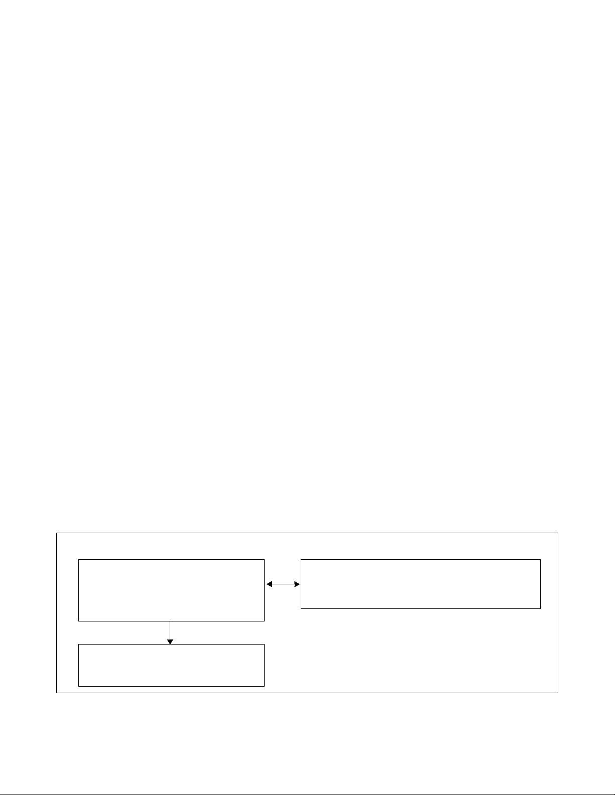
CHAPTER 1 INTRODUCTION
1. GENERAL
This manual describes routine system maintenance and fault repair procedures. This chapter explains how to
follow the manual and p rovides precaut ions pertaining t o maintenance jo bs as a whole. Be s ure to read thi s chapter thoroughly before starting the req uired maintenance job.
2. HOW TO FOLLOW THE MANUAL
If technicians engage in a fault repair with a sufficient amount of knowledge of the system (system
configurations, controlling systems, functions, etc.), the time spent repairing the system is minimized. This
manual provides explanations about the system, while placing emphasis on system configurations, controlling
systems, and functions. If fau lts of all conceivable cas es are to be assumed for the expl anations, the explanat ions
may lack reality and be more difficult to understand. Therefore, this manual provides the explanations on the
basis of the following points:
(1) It is very important to judge whether the fault has occurred in the system or at any of the peripheral
equipment.
(2) In case the system is faulty, explanations will be given about the actions to be taken until you identify the
faulty circu it card/cards.
(3) Explanations will be omitted pertaining to the following faults:
• Fault of peripheral equipment (MAT, telephone sets, etc.)
• Fault due to an error in office data assignment
• Fault due to an error in ins tall atio n proced ure (an er ror i n circ uit ca rd swit ch s etting, c ross- conn ecti on,
etc.)
(4) How to Read This Manual
• When a fau lt is to be repaired fo r the first time
See Section 3, How to Read Prec autions, Diagnostic,
See Section 3, How to Read Prec autions, Diagnostic,
Go to Chapter 5.
Go to Chapter 5.
See Section 4, Reporting Fault to NEC,
and F a ult Repair Information, Chapter 2.
and F a ult Repair Information, Chapter 2.
in Chapter 2.
NDA-24307 CHAPTER 1
Page 1
Issue 1
Page 30
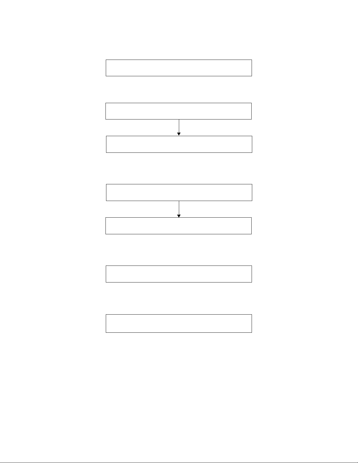
INTRODUCTION
• When only the contents of a system message needs to be known, or when a fault is to be diagnosed
from a system message
• When the range of faulty conditions has been specified and a faulty circuit card can be assumed
• When investigating the system for the purpose of a fault repair
Chapter 5
Chapter 5
See Section 4, Reporting Fau lt to NEC, in Chapter 2.
See Section 4, Reporting Fault to NEC, in Chapter 2.
Chapter 5
• When replacing a unit/circuit card with a spare
Chapter 4
• When performing routine maintenance
Chapter 7
CHAPTER 1 NDA-24307
Page 2
Issue 1
Page 31

CHAPTER 2 SYSTEM MAINTENANCE OUTLINE
1. GENERAL
1.1 Purpose
This chapter explains the outline of fault diagnosis and duties necessary to maintain the PBX.
1.2 Administrative Management Procedures
Figure 2-1 shows the work flow of the administrative management procedures.
Administrative
Management Works
Administrative Works
Expansion and Change of
Station Users
See Chapter 6
Traffic Management
Actions on Claims from
Station Users and/or Operators
Management Works
Station Message Detail
Recording System (SMDR)
Routine Diagnosis
Diagnosis result, system message displays abnormality
Routine Maintenance
System Status Monitor
Alarm Indications
Collection of System Messages
Indication of Lockout Stations
See Chapter 6
(B)
Office Data Management and Office
Data Protection
(A)
See Chapter 6
See Chapter 6
See Chapter 7
See Chapter 6
(A)
See Chapter 6
Fault Analysis/
Test Operation/
Changeover/
Make-Busy/Circuit
Card Change/
Initialization
(B)
Line fault
Circuit card fault
Terminal
(Tel., etc.) fault
Fault cause not
able to be localized
Refer to
Chapter 5
(Abnormal
Congestion)
Line Load Control
See Chapter 6
Figure 2-1 Flow of Administrative Management Procedures
NDA-24307 CHAPTER 2
Page 3
Issue 1
Page 32

SYSTEM MAINTENANCE OUTLINE
1.3 How to Follow This Manual
Table 2-1 provides a brief d es cription of the contents for each chapter in this manu a l.
Table 2-1 How to Follow This Manual Guide
CHAPTER DESCRIPTION
2 See Section 2, Basic Knowledge.
Explains basic knowledge of fault detection and indication, functions and fault range of the system,
etc.
See Section 3, How to Read Precautions, Diagnost ic, and Fault Repair Information.
Explains the methods of procedure performance and various symbols used in the description.
See Section 4, Reporting Fault to NEC.
Explains the method of forwarding faulty circuit cards, the method of creating a history record for
future fault repair, and the method of reporting faults to NEC.
3 Explains how to read and analyze system messages.
4 Explains the method of replacing a unit/circuit card due to a fault.
5 Explains repair procedures corresponding to the faults of processors or equipment.
6 Explains how to control the system in service management functions and precautions required in the
system control process.
7 Explains routine maintenance.
8 Explains the commands used in the system administrative management procedure.
2. BASIC KNOWLEDGE
This section identifi es the information nec essary for the system operations and maintenance procedures.
2.1 System Configuration
2.2 Line Equipment Numbers (LENS)
2.3 Loca l Partition (LP) Numb er
2.4 Assignment of Network Control Node (NCN)
2.5 System Messages
2.6 Fault Detecting Function
2.7 Range of Faults Specification
2.8 Explanation of Terms
CHAPTER 2 NDA-24307
Page 4
Issue 1
Page 33

SYSTEM MAINTENANCE OUTLINE
2.1 System Configuration
Figure 2-2 shows the system configuration of the fully expanded NEAX2400 IPX IPX-U.
LN0
ISW
......
......
LN1
LN3LN2
ISW: Inter-node Switch
LN: Local Node
FRONT VIEW
Figure 2-2 NEAX2400 IPX IPX-U
NDA-24307 CHAPTER 2
Page 5
Issue 1
Page 34

SYSTEM MAINTENANCE OUTLINE
2.1.1 Configuration of the System
The NEAX2400 IPX IPX-U system (referred to in the remainder of this manual as “the system”) is
configured by a single Inter-node Switch (ISW) and a maximum of 4 Local Nodes (LNs). Refer to
figures in this sec tion. The ISW and LNs are connec ted via the Fusion link, wit h Ethernet and physi cal
PCM cables connected to ea ch other. Figure 2-3 pro vides a n overall image of system configura tion. A
two-module ISW and maximum four Local nodes compose a single network system via the Fusion
link.
Ether
ISW
PCM Cable
LN0 LN1
IMG0 IMG1 IMG2 IMG3
TOPU TOPU TOPU TOPU
PIM3 PIM3 PIM3 PIM3
LN0/1/2/3
LN2 LN3
LN0
......
......
......
......
......
......
......
......
......
......
......
......
......
......
......
......
ISW
LN1
......
......
......
......
......
......
......
......
......
......
LN3LN2
......
......
......
......
......
......
......
......
PIM2 PIM2 PIM2 PIM2
ISW
TOPU
ISWM
LPM
BASEU
ISW: Inter-node Switch
LN: Local Node
TOPU: Top Unit
LPM: Local Processor Module
TSWM: Time Division Switch Module
ISWM:
FANU FANU FANU FANU
PIM1 PIM1 PIM1 PIM1
PIM0 PIM0 PIM0 PIM0
LPM TSWM0 TSWM1 DUMMY
BASEU BASEU BASEU BASEU
Inter-node Switch Module
Figure 2-3 System Configuration
CHAPTER 2 NDA-24307
Page 6
Issue 1
FRONT VIEWFRONT VIEW
PIM:
FANU:
Port Interface Module
Fan Unit
BASEU: Base Unit
Page 35

[ Details on PC M Cable Connections between ISW and LN ]
LN0
IM G0 IMG1 IMG 2 IMG3
TOPU TOPU TO PU TOPU
PIM3 PIM3 PIM3 PIM3
PIM2 PIM2 PIM2 PIM2
FANU FANU FANU FANU
PIM1 PIM1 PIM1 PIM1
PIM0 PIM0 PIM0 PIM0
LPM TSWM0 TSW M1 DUMMY
BASEU BASEU BASEU BASEU
SYSTEM MAINTENANCE OUTLINE
IPX-U
......
......
LN0
......
......
................................................
......
......
......
......
ISW
LN1
................................................
............
LN3LN2
......
......
......
......
......
......
......
......
< TSW M0 Ba ckplane >
TSW
(No. 1 System)
(19) (18) (17) (16) (15) (14) (13) (12)
To MUX
(IMG0/1)
TSW
(No. 0 System)
To MUX
(IMG0/1)
< TSW M 1 Backplane >
TS W
(No. 1 System)
(19) (18) (17) (16) (15) (14) (13) (12)
To MUX
(IMG2/3)
TSW
(No. 0 System)
To MUX
(IMG2/3)
To LN3
To LN2
To LN1
ISW
TOPU
ISWM
LPM
BASEU
< IS W M B ac k plan e >
TSW
(No. 1 System)
(17) (16) (15) (14) (07) (06) (05) (0 4)
PCM (ISW -LN TSW-CA -n ) C ab les
TS W
(No. 0 System )
For TSWM1
For TSWM0
Note:
For actual cable runnin gs, refer to the Installation Manual.
LN: L o ca l N o d e IS W: Inte r-n o d e S w itch
Figure 2-4 Details on Inter-node PCM Cable Connections
NDA-24307 CHAPTER 2
To LN3
To LN2
To LN1
Page 7
Issue 1
Page 36

SYSTEM MAINTENANCE OUTLINE
[Details on Ether Cable Connections]
ISW and each LN can achieve a Fusion link by physically connecting themselves via the 10 BASE-T cables. This figure
shows an example where the CPR-accommodated LANI cards (internal LANI: PCI slot 00) are mutually connected via
HUB0/HUB1 (PA-M96) cards in PIM0 of LN0, IMG0 (HUB0 for CPU0 of all nodes, HUB1 for CPU1 of all nodes.)
Note 1
IMG0 (LN0)
Note
HUB0 HUB1
From LN3
From LN2
From LN1
From ISW
HUB card can be mounted in any universal slot of PIM.
Note:
LANI
CPU1
CPU0
Note
PIM0
From LN3
From LN2
From LN1
From ISW
00
00
LPM
ISW / IMG0 (LN1/2/3)
LPM
LANI
CPU1
CPU0
00
00
To HUB1
in LN0
To HUB 1
in LN0
ISW
CPU1
L1
LN0
CPU1
L1
LN1
CPU1
L1
LN2
CPU1
L1
10 BASE-T Cables (Straight)
10 BASE-T
HUB1
Cables
(Cross)
HUB0
PIM0 of LN0, IMG0
10 BASE-T Cables (Straight)
Max. 328 ft (100m)
L1
CPU1
LN1
L1
CPU1
LN1
L1
CPU1
LN1
L1
CPU1
LN1
ISW: Inter-node Switch LN: Local Node LI: LANI (PZ-PC19) HUB: PA-M96
Note 1:
The connections , shown in this figure, are only an example. Actual cabl e running s may vary, depending o n your
system configuration. (Refer to the “Ins tallation Manual” for more details)
Note 2:
The mutual 10 BASE-T (Ethernet) connections must be within 328 feet (100m) in their distance. If the distance is
longer [e.g. , Fusion Link is provided also with other distant IPX node(s)], use FCH (P A-FCHA) card as a protocol
converter for the Fusion-link data. For more de tails, refer to the “Fusion Network System Manual.
LN3
CPU1
L1
Note 2
L1
CPU1
LN1
: 10 BASE-T connector
Figure 2-5 Details on Ethernet Cab le Connections (Establishment of Fusion Link) (1/2)
CHAPTER 2 NDA-24307
Page 8
Issue 1
Page 37

SYSTEM MAINTENANCE OUTLINE
[ Details on Ether Cable Connections: When Dual LANIs are used for each CPU ]
When dual LANIs are used for each CPU, the whole second LANIs (external LANI: PCI slot 03) must also be
connected in addition to the first LANIs explained on the previous page. This figure shows an example where the
second LANIs are connected to the additional HUB2/HUB3 (PA-M96) cards in PIM0 of LN2, IMG0 (HUB2 for
CPU0 of all nodes, HUB3 for CPU1 of all nodes).
Note 1
IMG0 (LN0)
IMG0 (LN2)
ISW / IMG0 (LN1/3)
Second LANI
LPM
10 BASE-T Cables (Straight)
CPU1
CPU0
00
00
ISW
CPU1
LI LI
03
03
10 BASE-T
Cables
(Cross)
To HUB3
in LN2
To HUB1
in LN0
To HUB2
in LN2
To HUB0
in LN0
From LN3
From LN2
From LN1
From ISW
LN0
CPU1
LI LI
HUB1
HUB0
HUB0 HUB1
Second LANI
CPU1
CPU0
LN0
03
00
03
00
LN1
CPU1
LI LI
10 BASE-T
Cables
(Cross)
PIM0
LPM
From LN3
From LN2
From LN1
From ISW
To HUB3
in LN2
To HUB2
in LN2
CPU1
LI LI
HUB3
HUB2
LN2
From LN3
From LN1
From LN0
From ISW
PIM0 of LN2, IMG0
HUB2 HUB3
PIM0
Second LANI
03
00
CPU1
03
00
CPU0
CPU1
LI LI
LN3
LPM
10 BASE-T Cables (Straight)
From LN3
From LN1
From LN0
From ISW
To HUB1
in LN0
To HUB0
in LN0
10 BASE-T Cables (Straight)
Note 1:
Note 2
LI LI
CPU0
LN1
LI LI
CPU0
LN2
LI LI
CPU0
ISW
Max. 328 ft (100m)
LI LI
CPU0
LN0
ISW: Inter-node Switch LN: Local Node LI: LANI (PZ-PC19) HUB: PA-M96
The above connections ar e only an e xample. Actual cable runnings may va ry , depending on your system
10 BASE-T Cables (Straight)
LI LI
CPU0
LN3
: 10 BASE-T connector
configuration (Refer to the “Installation Manual” for more details.)
Note 2:
The mutual 10 BASE-T (Ethernet) connections must be within 328 ft (100m) in their distance. If distance is longer (e.g., Fus ion link is provided with other distant IPX node(s), use FCH (PA-FCHA) card
as a pr otoco l converter for the Fusion link data. For more detai ls, refer to the “Fusion Network System
Manual.”
Figure 2-5 Details on Ethernet Cable Connections (Establishment of Fusion Link) (2/2)
NDA-24307 CHAPTER 2
Page 9
Issue 1
Page 38

SYSTEM MAINTENANCE OUTLINE
[ Details on Ether Cable Connections: When using MAT via Ethernet ]
The IPX-U system can use both IOC (PH-IO24) card or each CPR-accommodated LANI (PZ-PC19) card as
an interface for the connection to a MAT. This figure shows an example where a MAT is connected via the
LANI card in PCI slot 01 of each LN/ISW.
Fusion Link
Ether for MAT
This figure is an example where a MAT is connected to LN1 via the 10 BASE-T ca bles
(Ethernet). As seen from this, the MAT, a single terminal connected to the Ether, can control
the whole system status , thus capable of a single-point entry to each LN and ISW.
ISW
LN0 LN1 LN2 LN3
MAT
IMG0 (LN 1)
HUB
Note 1
HUB
Note 1
PIM0
LN1
IMG0 IMG1 IMG2 IMG3
Note 2
Note 1:
Note 2:
To LANI0 of LN3
To LANI0 of LN2
To LANI0 of LN0
To LANI0 of ISW
10 BASE-T Cable
(Straight)
MAT
When connecting the MAT by this way, be s ure to use dedicated HUB (PA-M96) car d( s).
Because ISW has no universal slot for external HUB cards, connect the 10 BASE -T cables (from the ISW) to a MAT-dedicated HUB in any of the LNs (LN0 - LN3). In this ex-
10 BASE-T Cable
(Cross)
CPU1
00
CPU0
010100
LANI
ample, the cables are ISW) to a MAT-dedicated HUB in any of the LNs (LN0 - LN3). In
this example, the cables are connected to HUB in LN1.
Note:
CHAPTER 2 NDA-24307
Page 10
Issue 1
The LANI card for MAT connection is mounted in PCI slot No. 01 of each CPR.
Figure 2-6 Details on Ethernet Cable Connections (Using MAT via Ethernet)
LPM
To LANI1 of LN3
To LANI1 of LN2
To LANI1 of LN0
To LANI1 of ISW
10 BASE-T Cable
(Straight)
Note 2
ISW
: Inter-node Switch
LN
: Local Node
LANI
: LANI (PZ-PC19)
HUB
: PA-M96
: 10 BASE-T connector
Page 39

TOPU
SYSTEM MAINTENANCE OUTLINE
ISW
Note:
13 14
IOGT1 (PH-GT10)
PLO1
(PH-CK16-A/17-A)
ISWM
LPM
BASEU
00 01 02 03 04 05 06 07 08 10 11 16 17 18 1915
PWR0 (PH-PW14)
HSW00 (PU-SW01)
PWR1 (PH-PW14)
TSW00 (PU-SW00)
HSW01 (PU-SW01)
TSW01 (PU-SW00)
TSW02 (PU-SW00)
09 12
TSW03 (PU-SW00)
IOGT0 (PH-GT10)
PLO0
(PH-CK16-A/17-A)
(RES)
03 04
01 02
00
MMC (PH-M22)
IOC (PH-IO24)
EMA (PH-PC40)
Note
FDD/HDDPWR DSP
The 2nd IOC card (optional) may be mounted in this slot.
TSW10 (PU-SW00)
TSW11 (PU-SW00)
TSW12 (PU-SW00)
TSW13 (PU-SW00)
HSW10 (PU-SW01)
LANI(PZ-PC19)
LANI(PZ-PC19)
LANI(PZ-PC19) LANI(PZ-PC19)
LANI(PZ-PC19)
LANI(PZ-PC19)
HSW11 (PU-SW01)
(RES)
ISAGT(PZ-GT13)
ISAGT(PZ-GT13)
Figure 2-7 Face Layout of ISW
NDA-24307 CHAPTER 2
Page 11
Issue 1
Page 40

SYSTEM MAINTENANCE OUTLINE
TOPU
00 01 02 03 04 05 06 07 08 09 10 11 12 13 14 15 16 17 18 19 20 21 22 23
PIM 3
00 01 02 03 04 05 06 07 08 09 10 11 12 13 14 15 16 17 18 19 20 21 22 23
PIM 2
FANU
00 01 02 03 04 05 06 07 08 09 10 11 12 13 14 15 16 17 18 19 20 21 22 23
PIM 1
IMG0 (Local Node)
PH-PC36 (MUX)
PH-PC36 (MUX)
PWR0
PWR1
PH-PC36 (MUX)
PH-PC36 (MUX)
PWR1
PWR0
PH-PC36 (MUX)
PWR1
PWR0
Note:
0000010102020303040405 06 07 08 09 10 11 12 13 14 15 16 17 18 19 20 21 22 23
PH-PC36 (MUX)
PH-PC36 (MUX) PH-PC36 (MUX)
PWR1
PWR0
PIM 0
Note
PH-PC40 (EMA)
PH-IO24 (IOC)
PH-I-M22 (MMC)
LPM
BASEU
The 2nd IOC card (optional) may be mounted in this slot.
Figure 2-8 Face Layout of IMG0 (Local Node)
CHAPTER 2 NDA-24307
Page 12
Issue 1
Page 41

IMG1 (Local Node)
TOPU
00 01 02 03 04 05 06 07 08 09 10 11 12 13 14 15 16 17 18 19 20 21 22 23
PA-PW 55-A (PWR0)
PA-PW 54-A (PWR1)
PWR1
PWR0
PIM 3
00 01 02 03 04 05 06 07 08 09 10 11 12 13 14 15 16 17 18 19 20 21 22 23
PA-PW 55-A (PWR0)
PA-PW 54-A (PWR1)
PWR0
PWR1
PIM 2
PH-PC36 (MUX)
PH-PC36 (MUX)
PH-PC36 (MUX)
PH-PC36 (MUX)
PH-PC36 (MUX)
PH-PC36 (MUX)
SYSTEM MAINTENANCE OUTLINE
FANU
PIM 1
PIM 0
TSWM0
BASEU
00 01 02 03 04 05 06 07 08 09 10 11 12 13 14 15 16 17 18 19 20 21 22 23
PH-PC36 (MUX)
PWR0
PWR1
0000010102020303040405 06 07 08 09 10 11 12 13 14 15 16 17 18 19 20 212122
PH-PC36 (MUX) PH-PC36 (MUX)
PH-PC36 (MUX)
PWR0
PWR1
PWRSW1
PWRSW0
05 06 07 08 09 10 11 12 13 14 15 16 17 18 19 20
MISC
MISC
MISC
DLKC0
DLKC1
GT0
GT1
TSW01
TSW00
TSW02
TSW03
MISC
MISC
TSW10
TSW11
TSW12
22 23
PLO0
TSW13
23
PLO1
Note:
No circuit card is mounted in Slot 02 of TSWM0.
Figure 2-9 Face Layout of IMG1 (Local Node)
NDA-24307 CHAPTER 2
Page 13
Issue 1
Page 42

SYSTEM MAINTENANCE OUTLINE
TOPU
00 01 02 03 04 05 06 07 08 09 10 11 12 13 14 15 16 17 18 19 20 21 22 23
PIM 3
00 01 02 03 04 05 06 07 08 09 10 11 12 13 14 15 16 17 18 19 20 21 22 23
PIM 2
PA-PW55-A (PWR0)
PWR0
PA-PW55-A (PWR0)
PWR0
PA-PW54-A (PWR1)
PWR1
PA-PW54-A (PWR1)
PWR1
IMG2 (Local Node)
PH-PC36 (MUX)
PH-PC36 (MUX)
PH-PC36 (MUX)
PH-PC36 (MUX)
PH-PC36 (MUX)
PH-PC36 (MUX)
FANU
PIM 1
PIM 0
TSWM1
BASEU
00 01 02 03 04 05 06 07 08 09 10 11 12 13 14 15 16 17 18 19 20 21 22 23
PH-PC36 (MUX)
PWR0
PWR1
0000010102020303040405 06 07 08 09 10 11 12 13 14 15 16 17 18 19 20 212122
PH-PC36 (MUX) PH-PC36 (MUX)
PH-PC36 (MUX)
PWR0
PWR1
PWRSW0
PWRSW1
05 06 07 08 09 10 11 12 13 14 15 16 17 18 19 20
MISC
MISC
MISC
MISC
GT0
MISC
GT1
TSW01
TSW00
TSW02
TSW03
TSW10
TSW11
TSW12
22 23
PLO0
TSW13
23
PLO1
Note:
No circuit card is mounted in Slot 02 of TSWM1.
Figure 2-10 Face Layout of IMG2 (Local Node)
CHAPTER 2 NDA-24307
Page 14
Issue 1
Page 43

IMG3 (Local Node)
TOPU
00 01 02 03 04 05 06 07 08 09 10 11 12 13 14 15 16 17 18 19 20 21 22 23
PH-PC36 (MUX)
PH-PC36 (MUX)
PWR1
PWR0
PIM 3
00 01 02 03 04 05 06 07 08 09 10 11 12 13 14 15 16 17 18 19 20 21 22 23
PH-PC36 (MUX)
PH-PC36 (MUX)
PWR1
PWR0
PIM 2
SYSTEM MAINTENANCE OUTLINE
FANU
PIM 1
PIM 0
DUMMY
00 01 02 03 04 05 06 07 08 09 10 11 12 13 14 15 16 17 18 19 20 2121222223
PH-PC36 (MUX)
PWR1
PWR0
00 01 02 03 04 05 06 07 08 09 10 11 12 13 14 15 16 17 18 19 20 21 22 23
PH-PC36 (MUX) PH-PC36 (MUX)
PH-PC36 (MUX)
PWR1
PWR0
BASEU
Figure 2-11 Face Layout of IMG3 (Local Node)
NDA-24307 CHAPTER 2
Page 15
Issue 1
Page 44

SYSTEM MAINTENANCE OUTLINE
2.2 Line Equipment Numbers (LENS)
The Line Equipment Numbers (LENS) are used to specify the location of a circuit (trunk/port) in any of
the PIM universal slots. Refer to the figures in this section, and confirm the LENS format used in the
system.
As shown in Figure 2-12, the LENs consists of six digits: two digits for MG, one digit for U, two digits
for G, and one digit for Lv.
LENS = XX X XX X
Lv (Level) : 0 - 7
Note:
In addition to Group No. 00-23, 24-31 can be used as the extended group numbers.
2.2.1 Module Group
Figure 2-13 explains the Module Group (MG). In a fully expanded system, the MG number ranges
from 00 to 07 in each local node.
IMG0
TOPU
PIM3
MG01
PIM2
G (Group) : 00 - 23
U (Unit) : 0 - 3
MG (Module Group) : 00 - 07
Figure 2-12 LENS Format
LN0/1/2/3
IMG1
TOPU
MG03
MG05
IMG2
TOPU
Note
IMG3
TOPU
MG07
FANU
PIM1
MG00
PIM0
LPM
BASEU
FANU
MG02
TSWM0
BASEU
FRONT VIEW
Figure 2-13 Module Group Allocations (LN0/1/2/3)
CHAPTER 2 NDA-24307
Page 16
Issue 1
FANU
MG04
TSWM1
BASEU
FANU
MG06
DUMMY
BASEU
Page 45

SYSTEM MAINTENANCE OUTLINE
2.2.2 Unit
Details on Unit (U) numbe rs are shown in Figure 2-14. The numbers range from 0 to 3, and each uni t
represents the PIM universal slots, No. 04-12 (U 0/2) or No. 15-23 (U 1/3).
On each Module Group (MG: #00 - 07), a total of four Units (U0 - U3) can be assigned.
LN0/1/2/3
PIM3
PIM2
PIM1
PIM0
Slots No.
IMG0
TOPU
U2
MG01
U0
U2
MG00
U0
BASEU
FANU
LPM
U3
U1
U3
U1
Unit Number (U = 0/2) Unit Number (U = 1/3)
00 02 04 05 06 07 08 09 10 11 12 13 14 15 16 17 18 19 20 21 22 23
IMG1
TOPU
U2
MG03
U0
U2
MG02
U0
TSWM0
BASEU
U3
U1
FANU
U3
U1
FRONT VIEW
U2
MG05
U0
FANU
U2
MG04
U0
TSWM1
BASEU
IMG2
TOPU
U3
U1
U3
U1
U2
MG07
U0
U2
MG06
U0
DUMMY
BASEU
IMG3
TOPU
U3
U1
FANU
U3
U1
Number
of
Time Slots
PWR
PWR
(16)(16)
Figure 2-14 Unit Number Allocations (LN0/1/2/3)
MUX (PH-PC36) 0
MUX (PH-PC36) 1
192 TS192 TS
16
16 16 16 16 16 32 32 32 16 16 16 16 16 16 32 32
16 16 16 16 16 16
Control Control
NDA-24307 CHAPTER 2
PIM
32
Page 17
Issue 1
Page 46

SYSTEM MAINTENANCE OUTLINE
2.2.3 Group
The Group (G) numbers are all ocated as shown in Figure 2-15. A tot al o f t wo Groups are assigned on
each universal slots within the PIM. Slot numbers 10, 11, 12, 21, 22, 23 can contain a total of four
Groups as an exception.
A total of two or four Groups (G) can be assig ned on eac h PIM uni ve rsal s lot.
LN0/1/2/3
PIM3
PIM2
PIM1
PIM0
IMG0
TOPU
U2
U0
U2
U0
U3
MG01
U1
FANU
U3
MG00
U1
LPM
BASEU
00 02 04 05 06 07 08 09 10 11 12 13 14 15 16 17 18 19 20 21 22 23
PWR
PWR
U2
MG03
U0
U2
MG02
U0
TSWM0
BASEU
IMG1
TOPU
U3
U1
FANU
U3
U1
U2
U0
U2
U0
MUX (PH-PC36 ) 1
IMG2
TOPU
MG05
FANU
MG04
TSWM1
BASEU
MUX (PH-PC36 ) 0
U3
U1
U3
U1
U2
MG07
U0
U2
MG06
U0
DUMMY
BASEU
IMG3
TOPU
FANU
U3
U1
U3
U1
Slot No. 05
G = 03
Slot No. 10
G = 15
16 ports total
G = 14
32 ports total
Note:
G = 02
PIM
G = 13
FRONT VIEW
G = 12
15
19
14
13
12
18
17
16
23
22
21
20
PIM
Group No.
Slot No.
Extended
Group No.
Note
01
00(25)(24)
27 29 31
26 28 30
04 05 06 07 08 09 10 11 12 13 14 15 16 17 18 19 20 21 22 23 00 02
030205040706090811
10
15
14
13
12
19
18
17
16
23
22
21
20
010003020504070609
08
27 29 31
26 28 30
11
10
U = 0 / 2 U = 1 / 3
In addition to Group No. 00 - 23, the system can use No. 24 - 31 as theoretically valid numbers.
Refer to the Fusion Network System Manual for information on Extended Group No. 26 - 31.
Figure 2-15 Group Number Allocations (LN0/1/2/3)
CHAPTER 2 NDA-24307
Page 18
Issue 1
Page 47

2.2.4 Level
Figure 2-16 explains the Level (Lv) numbers. There are a total of eight Levels (Lv0 - Lv7) on every
Group number, which ranges from 00 to 31.
A total of eight Levels (Lv0 - Lv7) c an be ass i gned on each Group.
LN0/1/2/3
IMG0
TOPU
PIM3
PIM2
PIM1
PIM0
U2
MG01
U0
U2
MG00
U0
BASEU
FANU
LPM
Group
(G = Odd No., < 11)
Group
(G = Even No., < 10)
U3
U1
U3
U1
Group No.
Level (Lv)
7
6
5
4
3
2
1
0
7
6
5
4
3
2
1
0
IMG1
TOPU
U2
U0
U2
U0
MG03
FANU
MG02
TSWM0
BASEU
U3
U1
U3
U1
FRONT VIEW
00 02 04 05 06 07 08 09 10 11 12 13 14
0100030205040706090811
(24) (25)
2726292831
IMG2
TOPU
U2
MG05
U0
FANU
U2
MG04
U0
DUMMY
BASEU
U = 0 / 2
10
30
IMG3
TOPU
U3
U1
U3
U1
15
19
23
14
18
22
13
17
21
12
16
20
16-port Slot
U2
U0
U2
U0
U = 1 / 3
15 16 17 18 19 20 21 22 23
0100030205040706090811
2726292831
MG07
FANU
MG06
DUMMY
BASEU
15
14
13
10
12
30
U3
U1
U3
U1
19
18
17
16
32-port Slot
SYSTEM MAINTENANCE OUTLINE
23
22
PIM
21
20
Level (Lv)
7
6
5
4
3
Group
(G = 15/19/23)
2
1
0
7
6
5
4
3
Group
(G = 14/18/22)
2
1
0
7
6
5
4
3
Group
(G = 13/17/21)
2
1
0
7
6
5
4
3
Group
(G = 12/16/20)
2
1
0
Figure 2-16 Level Number Alloc ations (LN0/1/2/3)
NDA-24307 CHAPTER 2
Page 19
Issue 1
Page 48

SYSTEM MAINTENANCE OUTLINE
2.3 Local Partition (LP) Number
The Local Partition (LP) number refers to a logical local processor number, theoretically assigned for each
IMG that consists of four (or less) Port Interface Modules (PIM). Though the local processor does not
actually e xist in any of the IM Gs, ex cept for IMG0, the system can apply the tw o-digit LP number to each
IMG (see Figure 2-17) on i ts data memory program. The LP numbers are used primaril y i n the followi ng
cases:
• Display of system messages
• Assignment of line load control data (ALLC command)
• Backup for Call Forwarding/Speed Calling data (MEM_HDD command), etc.
The Local Partition No. (two digits, even number) is assigned on each IMG.
IMG0
TOPU
PIM3
IMG1
TOPU
PIM3
LN0/1/2/3
IMG2
TOPU
PIM3
IMG3
TOPU
PIM3
PIM2
FANU
PIM1
PIM0
LPM
BASEU
LP No. = 00 LP No. = 02 LP No. = 04 LP No. = 06
PIM2
FANU
PIM1
PIM0
TSWM0
BASEU
FRONT VIEW
PIM2
FANU
PIM1
PIM0
TSWM1
BASEU
PIM2
FANU
PIM1
PIM0
DUMMY
BASEU
Figure 2-17 LP Number Allocations (LN0/1/2/3)
CHAPTER 2 NDA-24307
Page 20
Issue 1
Page 49

SYSTEM MAINTENANCE OUTLINE
2.4 Assignment of Network Control Node (NCN)
The IPX-U system can be in service by dialing a T elephone Number assigned for each station at a Network
Control Node (NCN). Because these network-level data (NDM data) can be assigned via the MAT
dedicated to the NCN only, designate any of the following nodes as this network data manager (NCN):
• One of the Local Nodes (LN), excepting for the ISW, within the IPX-U system
• One of the belonging Fusion nodes outsi de the IPX-U system
For more det ails, refer to Figure 2-18.
Note 1:
W ithin the IPX-U sys tem, the NCN can be designat ed only fr om the Loca l Nodes (LN0-LN3). The ISW
cannot be assigned as the NCN.
Note 2:
On a Fusion network, assign only one NCN. Multiple nodes cannot be assigned as the NCN.
Because the Fusion link can be es tablished e ither independe ntly within the syste m (IPX-U) or jo intly with
other outside IPX series, the assignment of NCN can differ, depending on the network configuration.
NDA-24307 CHAPTER 2
Page 21
Issue 1
Page 50

SYSTEM MAINTENANCE OUTLINE
Pattern 1 When the system has a Fusion link independently of other systems
If the system has a Fusion li nk only within the system (i.e. no Fusi on link is esta blished with ot her IPX
series), an NCN must be assigned from any of the existing Local Nodes, excepting the ISW. In this
example, LN0 is assigned as the NCN.
Ne twor k Data Me mor y
-Sy s te m Data
AS Y DN, AFMU, ALRTN ....
-Number Planning Data
ANPDN, ASPAN....
-Station Num b ering
ALGN N , ALG SN....
......
Station A
TELN: 41000
No te 1
DM
LDM
NDM
Assignment of NDM Data
via Cen tr a lized MA T
Station C
TELN: 43002
NDM
(FP C =1 6)
......
......
......
......
......
......
......
......
(FP C =1 8)
LN2
......
......
......
......
LN0
......
......
......
......
......
......
......
......
......
......
N
D
M
D
a
Network Control Node
t
a
C
o
p
y
(FPC = 1 7)
LN1
......
......
......
......
......
......
......
......
Station B
TELN: 420 05
No te 2
(FPC=15)
IS W
......
......
......
......
NDM
(FPC = 1 9)
LN3
......
......
......
......
......
......
NDM
NDM
......
......
Station D
TELN: 450 07
IS W : In te r-n o d e S w itc h
LN : L o c a l Node
NCN: Network Control Node
Note 1:
The network-lev el data (NDM data) can be assig ned only at th e NCN. Howeve r, other node-level
D M : D ata Memo ry
LDM: Local Data M e mory
NDM: Network Data Memory
data (LDM data) must also be assigned at each node (including ISW), depending on the
requirements. For more details, refer to the “Installation Manual (IPX-U Type)” or the “Fusion
Network System Manual.”
Note 2:
When the system is oper ated, th e funct ion to be performed by t he ISW is only t o provide the PCM
time slot switching between the Local Nodes. However, an FPC (Fusion Point Code) must be assigned also for the ISW together with other Local nodes, by using the ASYDL command.
Figure 2-18 Example of NCN Assignment (1/3)
CHAPTER 2 NDA-24307
Page 22
Issue 1
< IPX-U >
FPC : F u s io n Po int C od e
TELN: Telephone Number
MAT : Maintenance Ad mini strati on T erm i n al
Page 51

SYSTEM MAINTENANCE OUTLINE
Pattern 2 When the system has a Fusion link with other IPX series and an NCN exists within the system
If the system has a Fusion link also with other IPX series (i.e. the Fusion nodes exist also outside the
system), an NCN can be assigned from either Local Nodes outside the system or the Local Nodes
inside the system. In this e xample, LN0 of the IPX-U system is designated as the NCN.
Network Data Memory
-System Data
ASYDN, AFMU, ALR TN ....
-Number Planning Data
ANPDN, ASPAN....
-Station Numbering
ALGNN, ALGSN....
......
Station A
TELN: 41000
NDM
Assignment of ND M Data
via C en tra lized M A T
Station C
TELN: 43002
Fusion Link
(FPC = 1 6 )
LN0
......
......
......
......
......
......
......
......
......
......
......
......
Note 1
DM
LDM
N
(FPC=18)
LN2
................................................
NDM
IPX-U
System
Sta tio n E
TELN: 47001
Network Contro l Node
......
......
......
......
D
M
D
a
t
a
C
o
p
y
Note 2
(FPC = 1 5 )
ISW
......
......
Sta tio n G
TELN: 49012
(FPC = 1 )
LN-A
................................................
NDM
NDM
(FPC=3)
LN-C
NDM
(FPC = 1 7 )
LN1
......
......
......
......
......
......
......
......
(FPC=19)
LN3
......
......
......
......
........................
(FPC = 2 )
............
......
......
LN-B
Station B
TELN: 42005
NDM
......
......
Station D
TELN: 45007
NDM
Station F
TELN: 48003
NDM
Note 1:
Note 2:
IS W : I n t e r -no de Switc h
LN : Local No de
NCN : Network Control Node
D M : D ata M e mory
LDM: L oc al Da ta Me mory
NDM: Network Data Memory
FPC : Fusion Point Code
TELN: Tel ephone Number
MAT : Maintenance Administration T erminal
The network-level data (NDM data) can be assigned only at the NCN. However, other nodelevel data (LDM data) must also be assigned at each node (including ISW), depending on the
requirements. For more details, refer to the “Installation Manual (IPX-U Type)” or the
“Fusion Network System Manual.”
When the system is operated, the function to be performed by the ISW is only to provide PCM
time slo t switching b etween the Local Nodes. However, an FPC (Fusion Point Code) mus t be
assigned also for the ISW together with other Local nodes, by using the ASYDL command.
Figure 2-18 Example of NCN Assignment (2/3)
NDA-24307 CHAPTER 2
Page 23
Issue 1
Page 52

SYSTEM MAINTENANCE OUTLINE
Pattern 3 When the system has a Fusion link with other IPX series and an NCN exists outside the system
If the system has a Fusion link also with other IPX series (i.e. the Fusion nodes exist also outside the
system), an NCN can be assigned from either Local Nodes outside the system or the Local Nodes
inside the system. In this example, LN-A (NEAX2400IPX series, 4-IMG type) outside the system is
designated as the NCN.
(FPC = 1)
LN-A
......
......
......
Network Data Memory
-System Data
ASYDN, AFMU, ALRTN....
-Number Planning Data
ANPDN, ASPAN....
-Station Numbering
ALGNN, ALGSN....
......
Station E
TELN: 47001
Note 1
DM
LDM
NDM
Assignment of NDM D ata
via Centralized MAT
......
......
......
......
......
......
......
......
......
......
......
......
......
Network Control N ode
NDM Data Copy
(FP C=2 )
LN-B
Statio n F
................................................
TELN: 48003
............
Note 1:
(FPC= 3)
LN-C
......
......
......
Station G
TELN: 49012
LN1
................................................
LN3
................................................
......
NDM
Station B
TELN: 42005
NDM
Station D
NDM
TELN: 45007
Fusion Link
ISW : Inter-node Switch
LN : Lo ca l N o de
NCN: Network Control Node
(FPC=16)
Station A
TELN: 41000
TELN: 43002
Station C
LN0
NDM
(FPC=18)
LN2
......
......
......
......
NDM
DM : D ata M e mory
LDM: Local Data Me m ory
NDM: Network Data Memory
IPX- U
System
................................................
......
......
......
......
NDM
(FPC=17)
No te 2
(FPC=15)
ISW
............
(FPC=19)
NDM
FPC : Fusion Point C ode
TELN: Telephone Number
MAT : M aintenance Administration Terminal
The network-level data (NDM data) can be assigned only at the NCN. However, other node-level
data (LDM data) must also be assigned at each node (including ISW), depending on the
requirements. For more details, refer to the “Installation Manual (IPX-U Type)” or the “Fusion
Network System Manual.”
Note 2:
When the system is operated, the function to be performed by the ISW is on ly to pro vi de the PCM
time slot switching between the Local Nodes. However, a FPC (Fusion Point Code) must be
assigned also for the ISW together with other Local nod e s , by u s i ng the ASYDL command.
Figure 2-18 Example of NCN Assignment (3/3)
CHAPTER 2 NDA-24307
Page 24
Issue 1
Page 53

SYSTEM MAINTENANCE OUTLINE
2.5 System Messages
System messages display during routine diagnosis, system operation status controlling, and fault
occurrence. Figure 2- 19 shows an example of a system message.
Refer to Chapter 3 for details on each message.
(1) SYSTEM MESSAGE 3-E SUP LOCK UP FAILURE (TEMPORARY)
(2) NEC TOKYO
(3) LP00-0-ACT
Note 1
JUL 24 09:35
(4)
Meaning:
1:1102 0000 0000 0000 2:0000 0000 0000 0000 3:0000 0000 0000 0000
4:0000 0000 0000 0000 5:0000 0000 0000 0000 6:0000 0000 0000 0000
7:0000 0000 0000 0000 8:0000 0000 0000 0000 9:0000 0000 0000 0000
(1) : SYSTEM MESSAGE 3-E SUP LOCK-UP FAILURE (TEMPORARY)
Meaning of the message
System Message Level
(Indicated by Alarm Lamp)
System Message Number
(2) : Office Name, Date and Time
(3) : LP00-0-ACT
ACT/STBY indication for dual systems
Note 2
No.0/No.1 system indication for dual systems
Faulty processor/Related processor
(4) : Message detail data (notation by hexadecimal numbers)
Note 1:
The data here indicates the Office Name, uniquely assigned to each node and ISW. This
can be set by using the ASYD (SYS1, Index 96-115) or AOFC command.
Note 2:
There are four kinds of al a rm informati on to be indica ted by alarm lamps: MN, MJ, SUP,
and NON indications.
Figure 2-19 System Message Example
NDA-24307 CHAPTER 2
Page 25
Issue 1
Page 54

SYSTEM MAINTENANCE OUTLINE
2.6 Fault Detecting Function
The system fin ds a f ault b y its f aul t dete cting c ircui t and th e f aul t detec ting progr am. Once a fa ult occ urs,
the system initiates a remedial action such as system changeover, make-busy setting, or restart processing
by the automatic di agnosis func tion. This ac tion reduces the influe nce of the f ault so t hat system ser vicing
may be minimized. The result of the process ta ken and the fault situat ion are indica ted for equipmen t concerned.
Among the faults, those related to speech path (noise , one-way speech, sp eech inability, etc.) are not
detectable. Since t hese f ault r eports a re to be obtaine d from a s tation o r operator, periodic trunk tests mus t
be performed without failure to detect the faults related to speech path.
Figure 2-20 and Figure 2-21 shows an outline of fault detection, and Figure 2-23 shows a block diagram
of fault detect ion.
CHAPTER 2 NDA-24307
Page 26
Issue 1
Page 55

SYSTEM MAINTENANCE OUTLINE
LN0
LN1
ISW
Indication
of Audible
and Visual Alarm
Indicating Panel
Indication of Fault Occurrence Information Collection
MMC
......
Indication of
Alarm Lamps
on TOPU
MMC
Indication of
Alarm Lamps
on TOPU
NEC
MJ
OFF
ON
BELL
MMC
......
......
......
and Diagnosis
CPU
EMA
CPU
EMA
CPU
Example of Faults
Fault of line/trunk card
TSW write failure,
Fault of clocks, etc.
Abnormal temperature,
power supply failure,
fuse blowing, etc., within
the equipment frame
Fault of line/trunk card
TSW write failure,
Fault of clocks, etc.
Abnormal temperature,
power supply failure,
fuse blowing, etc., within
the equipment frame
Fault of line/trunk card
TSW write failure,
Fault of clocks, etc.
Indication of
Alarm Lamps
on TOPU
......
......
EMA
Abnormal temperature,
power supply failure,
fuse blowing, etc., within
the equipment frame
LN2
MMC
Indication of
Alarm Lamps
on TOPU
CPU
......
......
EMA
Fault of line/trunk card
TSW write failure,
Fault of clocks, etc.
Abnormal temperature,
power supply failure,
fuse blowing, etc., within
the equipment frame
LN3
MMC
CPU
Fault of line/trunk card
TSW write failure,
Fault of clocks, etc.
Abnormal temperature,
Indication of
Alarm Lamps
on TOPU
......
EMA
power supply failure,
fuse blowing, etc., within
......
the equipment frame
Note: Alarm Indicating Panel indicates the fault information on both ISW and other Local Nodes (fault notification on a system
basis). Meanwhile, alarm lamps on the TOPU for ISW and Local Nodes (indicated in dotted lines above) provide the fault
indication only related to the belonging node. For more details, refer to CHAPTER 6.
Figure 2-20 Fault Detection General Diagram (via Alarm Lamps on TOPU)
NDA-24307 CHAPTER 2
Page 27
Issue 1
Page 56

SYSTEM MAINTENANCE OUTLINE
LN0
LN1
Display of
System Messages
ISW
Indication of Fault Occurrence Information Collection
...-:;..+..*
...-:;..+..*
...-:;..+..*
...-:;..+..*
Display of
System Messages
LANI
and Diagnosis
IOC
CPU
MMC
EMA
...-:;..+..*
...-:;..+..*
...-:;..+..*
...-:;..+..*
Display of
System Messages
LANI
...-:;..+..*
...-:;..+..*
...-:;..+..*
...-:;..+..*
MMC
IOC
CPU
EMA
...-:;..+..*
...-:;..+..*
...-:;..+..*
...-:;..+..*
IOC
CPU
LANI
Display of
System Messages
Example of Faults
Fault of line/trunk card
TSW write failure,
Fault of clocks, etc.
Abnormal temperature,
power supply failure,
fuse blowing, etc., within
the equipment frame
Fault of line/trunk card
TSW write failure,
Fault of clocks, etc.
Abnormal temperature,
power supply failure,
fuse blowing, etc., within
the equipment frame
Fault of line/trunk card
TSW write failure,
Fault of clocks, etc.
Abnormal temperature,
power supply failure,
fuse blowing, etc., within
the equipment frame
Fault of line/trunk card
TSW write failure,
Fault of clocks, etc.
Abnormal temperature,
power supply failure,
fuse blowing, etc., within
LN2
Ether
LANI
MMC
MMC
...-:;..+..*
...-:;..+..*
Display of
System Messages
EMA
...-:;..+..*
...-:;..+..*
IOC
CPU
EMA
the equipment frame
...-:;..+..*
...-:;..+..*
...-:;..+..*
Display of
System Messages
...-:;..+..*
IOC
Fault of line/trunk card
LN3
TSW write failure,
LANI
MMC
CPU
EMA
Fault of clocks, etc.
Abnormal temperature,
power supply failure,
fuse blowing, etc., within
the equipment frame
- Symbols EMA: PH-PC40 MMC: PH-M22 LANI: PZ-PC19 IOC: PH-IO24
Note: In addition to the connection to a port of IOC (PH-IO24) circuit card, a MAT can be connected also to the
Ethernet via LAN Interfaces (PZ-PC19: PCI Slot 01 of each CPR).
Figure 2-21 Fault Detection Block Diagram (via Display of System Messages)
CHAPTER 2 NDA-24307
Page 28
Issue 1
Page 57

SYSTEM MAINTENANCE OUTLINE
< LN >
Firmware
Fault
RDY
Clock
etc.
To M AT,
Printer, etc.
LANI
- Symbols -
: Circuit Card
: Main faults to be detected
: Speech path
: Flow of fault information
CPU
:Central Processing Unit
EMA
:Emergency Alarm Controller
MMC
:Man Machine Controller
TSW
:Time Division Switch
INT
:Speech Path Control Interface
MUX
:Multiplexer
HSW
:Highway Switch
DLKC
:Data Link Controller
PWR
:Power Supply
LANI
:Local Area Network Interface
IOC
:I/O Controller
GT
:Gate
IOGT
:Input/Output Gate
LC/TRK
:Line/Trunk
MAT
:Maintenance Administration Terminal
LN
:Local Node
TSWM
:Time Division Switch Module
ISW
:Inter-node Switch
ISWM
:Inter-node Switch Module
RDY
Clock
Write
etc.
IOC
MMC
MUX
RDY
Clock
Write
etc.
C-level
monitor
LC/TRK
TSW/
INT
RDY
Clock
Write
etc.
CPU
Fault
Information
Note
To TSW
of ISWM
TSW/
INT
DLKC
TSWM0
C-level
monitor
From
other existing
Local Nodes
Howler
Ringing
Circuit
EMA
Alarm Lamps on the TOPU
Thermal Reed Relay
LC/TRK
MUX
RDY
TSW/
Clock
INT
Write
etc.
RDY
Clock
Write
etc.
GTGT
PWR
PWR Supply
Failure,
Fuse Blown
To TSW
of ISWM
TSW/
INT
TSWM1
MMC
To MAT
on the Ethernet
To M AT,
Printer, etc.
< LN >
To M AT,
Printer, etc.
LANI
From
other
nodes
LANI
Firmware
Fault
RDY
Clock
etc.
IOC
RDY
Clock
Write
etc.
RDY
Clock
Write
etc.
GT
C-level
monitor
IOC
MMC
CPU
Fault
Information
Note
LC/TRK
MUX
TSW/
INT
RDY
Clock
Write
etc.
CPU
Fault
Information
Note
Note:
C-level
monitor
Alarm Lamps on the TOPU
Thermal Reed Relay
LC/TRK
DLKC
TSWM0
C-level
monitor
To TSW
of ISWM
TSW/
INT
Howler
Ringing
Circuit
EMA
RDY
Clock
Write
etc.
GT
PWR Supply
Failure,
Fuse Blown
PWR
MUX
RDY
Clock
Write
etc.
TSW/
INT
To TSW
of ISWM
TSWM1
MJ, MN fault
Power, Fuse blown fault
Temperature, CPU fault
Speech Path System fault (SPE)
RGU, Howler fault
PFT fault
CPU Clock fault
Alarm Lamps on the TOPU
Thermal Reed Relay
To/From TSW
of each LN
RDY
TSW/
Clock
INT
Write
Howler
Ringing
Circuit
EMA
etc.
IOGT
PWR
PWR Supply
Failure,
Fuse Blown
RDY
Clock
Write
etc.
HSW
ISWM
< ISW >
TSW/
INT
Figure 2-22 Fault Detection Block Diagram
NDA-24307 CHAPTER 2
Page 29
Issue 1
Page 58

SYSTEM MAINTENANCE OUTLINE
(a) Main Faults
Faults that may o ccur in the syst em can be general ly categor ized into Processo r System F ault, Speech
Path System Fault, Line/Trunk Fault, etc.
• Proces sor System Fault
The CPU alarm detecting circuit contin uously monitors whether the CPU is working normally. If
a fault is detected, the CPU calls up the diagnostic program, which identifies the cause of the fault
and determines whether the fault is temporary or permanent. When the fault affects system
operations, Active/Standby status of the CPU is changed over (provided that the system has dual
configuration).
• Bus System Fault
The CPU transfers line/trunk card control information to the associated peripheral circuits via IO
Bus. When a parity error is detected in the transfer data or when the required information cannot
be transferred from a circuit card, the CPU identifies the cause of the fault, changes over the CPU
so that system operation is not affected, and executes restart processing.
• Speech Path Fault
The CPU monitors the operating status of the TSW card, the occurrence of errors in writing data
to the switch memory, and the basic clocks s upplied t o the spee ch path. Upon detecti ng a fau lt, the
CPU identifies the cause of the fault, determines whether the fault is temporary or permanent, and
executes required processing such as changeover of the TSW card.
• Others
The alarm detecting circui t on the EMA card con tinuousl y monitors the occ urrence of fa ults in the
PWR supply cards, such as abnormal temperatures within the equipment frame, and lights the
alarm lamp on the TOPU when a fault is detected.
(b) Lamp Indications on the TOPU
When a fault occurs, the corr esponding lamp on the T OPU indicate s the locati on of the f ault. F or the
meaning of each lamp indication, refer to Chapter 6.
CHAPTER 2 NDA-24307
Page 30
Issue 1
Page 59

SYSTEM MAINTENANCE OUTLINE
2.7 Range of Faults Specification
(1) Upon receiving a fault report from a station user or an operator, the technician can assume a faulty card
exists if the range to be affected by the fault can be determined. For the de tailed procedure, re fer to
Chapter 5. Use the following actions to check the MDF:
(a) Check the LENS of the reporter (Station or ATTCON/DESKCON).
(b) Check other circuits of the circuit card in which the reporter (station line or ATTCON/DESKCON)
is located.
(c) Check the other groups (ot her ci rcuit car ds mounte d in t he sa me modul e) i n the module i n wh ich th e
reporter is located.
(d) Check lines in each of the other modules on the basis of plural lines.
(2) If the fault cannot be detecte d by the system (a f ault related to the speech path such a s noise during speec h,
one-way speech, speech inability), the range of (a) through (d) (itemized above) should be limited.
(3) When a major faul t is det e cted i n the du al sys te ms , the C PU or TS W sy st em auto m ati c al ly ch ang es over
if the fault ra nge is (c) an d (d). In th is case, the w hole modul e involved is placed into m ake-busy sta tus
even if the fault is partial, and the station lines currently operating normally become faulty status.
Diagnose the fault from the content of the system message displayed and repair the fault as required.
(4) When limiting the range of faults, consider the system circuitry that consists of the control (see Figure 2 -
24 and Figure 2-25, where CPU 0 is active) and speech path systems (see Figure 2-26).
(5) As seen from the block diagrams in Figure 2-24 through Figure 2-27, if a fault occurs within the common
portions to be controlled, all other associated portions are affected by that fault occurrence. If the range
of faults is outside PIM fault, CPU/TSW system changeover is executed (only when the fault is detectable
by the system).
NDA-24307 CHAPTER 2
Page 31
Issue 1
Page 60

SYSTEM MAINTENANCE OUTLINE
:
:
Note 1
HSW00, 01 for No. 0 System /
HSW10, 11 for No. 1 System
Note 2
ISW-LN TSW CA-n Cables
Note 3
ISW-LN PLO CA-n Cables
Note 4
PLO-CLK CA-n Cables
Circuit Card
(No. 0 System)
Circuit Card
(No. 1 System)
To MUX
(IMG0)
TSW00 TSW01 TSW02 TSW03
DLKC
TSWM0
IOC
EMA
MISC
To MUX
(IMG1)
GT
ISAGT-A
CPU
LANI
To MUX
(IMG2)
TSW00 TSW01 TSW02 TSW03
PLO CLK
Note 4
To MUX
(IMG3)
GT
ISAGT-B
TSWM1
LN1
To TSW
Note 2
Note 1
HSW
MISC
ISW
TSW00
IOC EMA
of LN2
TSW01 TSW02
IOGT
ISAGT
CPU
LANI
TSW03
PLO
To TSW
of LN3
Note 3
To PLO of
LN2/3
To MUX
To MUX
(IMG0)
(IMG1)
TSW00 TSW01 TSW02 TSW03
GT
ISAGT-A
CPU
LANI
PLO
DLKC
TSWM0 TSWM1
MISC
IOC
EMA
To MUX
(IMG2)
TSW00 TSW01 TSW02 TSW03
CLK
Note 4
To MUX
(IMG3)
GT
ISAGT-B
LN0
Fusion Link
< ISW (Inter-node Switch) >
ISAGT: PZ-GT13 LANI: PZ-PC19 IOGT: PH-GT10 TSW: PU-SW00
HSW: PU-SW01 PLO: PH-CK16/17-A EMA: PH-PC40 IOC: PH-IO24
< LN (Local Node) >
ISAGT-A: PZ-GT13 ISAGT-B: PZ-GT20 LANI: PZ-PC19 GT: PH-GT09 TSW: PH-SW12 MUX: PH-PC36
DLKC: PH-PC20 PLO: PH-CK16-A CLK: PH-CK18 EMA: PH-PC40 IOC: PH-IO24
Note:
For details on each equipment’s switching network, see Chapter 6, System Control
Procedures.
Figure 2-23 General System Block Diagram (1/2)
CHAPTER 2 NDA-24307
Page 32
Issue 1
Page 61

Circuit Card
:
(No. 0 System)
Circuit Card
:
(No. 1 System)
Note 1
HSW00, 01 for No. 0 System /
HSW10, 11 for No. 1 System
Note 2
ISW-LN TSW CA-n Cables
SYSTEM MAINTENANCE OUTLINE
To MUX
To MUX
(IMG0)
(IMG1)
TSW00 TSW01 TSW02 TSW03
DLKC
TSWM0 TSWM1
PLO CLK
GT
To MUX
To MUX
(IMG2)
(IMG3)
TSW00 TSW01 TSW02 TSW03
Note 4
GT
Note 3
ISW-LN PLO CA-n Cables
Note 4
PLO-CLK CA-n Cables
To TSW
To TSW
of LN0
of LN1
Note 2
Note 1
HSW
TSW00
TSW01 TSW02
IOGT
ISAGT
MISC
IOC EMA
ISW
CPU
LANI
PLO
To PLO of
LN0/1
TSW03
Note 3
ISAGT-A
MISC
IOC EMA
CPU
LANI
To MUX
To MUX
(IMG0)
(IMG1)
TSW00 TSW01 TSW02 TSW03
GT
ISAGT-A
CPU
LANI
PLO
DLKC
TSWM0 TSWM1
MISC
IOC EMA
To MUX
(IMG2)
TSW00 TSW01 TSW02 TSW03
CLK
Note 4
To MUX
(IMG3)
GT
ISAGT-B
ISAGT-B
LN3
LN2
Fusion Link
< ISW (Inter-node Switch) >
ISAGT: PZ-GT13 LANI: PZ-PC19 IOGT: PH-GT10 TSW: PU-SW00
HSW: PU-SW01 PLO: PH-CK16/17-A EMA: PH-PC40 IOC: PH-IO24
< LN (Local Node) >
ISAGT-A: PZ-GT13 ISAGT-B: PZ-GT20 LANI: PZ-PC19 GT: PH-GT09 TSW: PH-SW12 MUX: PH-PC36
DLKC: PH-PC20 PLO: PH-CK16-A CLK: PH-CK18 EMA: PH-PC40 IOC: PH-IO24
Note:
For details on each equip m ent’s switching network, see Chapter 6, System Control Procedures.
Figure 2-23 General Block Diagram of the Whole System (2/2)
NDA-24307 CHAPTER 2
Page 33
Issue 1
Page 62

SYSTEM MAINTENANCE OUTLINE
This figure shows a block diagram of the CPU controlling block in ISW, where CPU 0 is active.
Note 2
CPR
CPU clock
PCI BUS
LANI
To TSWM1 of LN3
To TSWM0 of LN3
To TSWM1 of LN2
To TSWM0 of LN2
To TSWM1 of LN1
To TSWM0 of LN1
To TSWM1 of LN0
To TSWM0 of LN0
T
ISAGT 0
M
ISA BUS
CPU 0
MEMORY
CPU board
TSW I/O BUS
Note 1 Note 1
HSW 00
03F
TSW
03E
TSW
03D
TSW
03C
TSW
03B
TSW
03A
TSW
039
TSW
TSW/
038
TSW
037
TSW
INT
036
TSW
035
TSW
034
TSW
033
TSW
032
TSW
031
TSW
030
TSW
TSW 03
02F
TSW
02E
TSW
02D
TSW
02C
TSW
02B
TSW
02A
TSW
029
TSW
TSW/
028
TSW
027
TSW
INT
026
TSW
025
TSW
024
TSW
023
TSW
022
TSW
021
TSW
020
TSW
TSW 02
01F
TSW
01E
TSW
01D
TSW
01C
TSW
01B
TSW
01A
TSW
019
TSW
018
TSW
TSW/
017
TSW
016
TSW
INT
015
TSW
TSW
TSW
TSW
TSW
TSW
TSW
TSW
TSW
TSW
TSW
TSW
TSW
TSW
TSW
TSW
TSW
TSW
TSW
TSW
TSW
TSW
014
013
012
011
010
TSW 01
00F
00E
00D
00C
00B
00A
009
008
007
006
005
004
003
002
001
000
TSW 00
TSW/
INT
IOP1
TSW I/O BUS
MISC BUS
PLO 1
PLO 0
Note 3
MISC BUS
IOP0
IOGT 1IOGT 0
- Symbols : Controlling Routes of CPU : Cable
: Circuit card (active) : Circuit card (ST-BY)
: External Cable : Clock Oscillator
: Signal
EMA: PH-PC40
LANI: PZ-PC19
IOC: PH-IO24
ISAGT: PZ-GT13
IOGT: PH-GT10
To LPM
of LN0
Reset Signal
PWR
MISC BUS
EMA
PWR
(ST-BY)
IOC /
MISC
MISC BUS
ISAGT 1
CPR
(ST-BY)
T
M
CPU board
LPM of ISW
HSW 11HSW 01
HSW 10
TSW/
INT
TSW/
INT
TSW/
INT
TSW/
INT
TSW
TSW
TSW
TSW
TSW
TSW
TSW
TSW
TSW
TSW
TSW
TSW
TSW
TSW
TSW
TSW
TSW 13
TSW
TSW
TSW
TSW
TSW
TSW
TSW
TSW
TSW
TSW
TSW
TSW
TSW
TSW
TSW
TSW
TSW 12
TSW
TSW
TSW
TSW
TSW
TSW
TSW
TSW
TSW
TSW
TSW
TSW
TSW
TSW
TSW
TSW
TSW 11
TSW
TSW
TSW
TSW
TSW
TSW
TSW
TSW
TSW
TSW
TSW
TSW
TSW
TSW
TSW
TSW
TSW 10
ISWM
13F
13E
13D
13C
13B
13A
139
138
137
136
135
134
133
132
131
130
12F
12E
12D
12C
12B
12A
129
128
127
126
125
124
123
122
121
120
11F
11E
11D
11C
11B
11A
119
118
117
116
115
114
113
112
111
110
10F
10E
10D
10C
10B
10A
109
108
107
106
105
104
103
102
101
100
To LPM
of LN1
To TSWM1 of LN3
To TSWM0 of LN3
To TSWM1 of LN2
To TSWM0 of LN2
Note 2
To TSWM1 of LN1
To TSWM0 of LN1
To TSWM1 of LN0
To TSWM0 of LN0
TSW: PH-SW00
HSW: PH-SW01
MUX: PH-PC36
PLO: PH-CK16-A/17-A
CLK: PH-CK18
To LPM
of LN2
To LPM
of LN3
Fusion Link
Note 1:
The two HSW cards here provide the space division switching for a maximum of 16 PCM
highways fr om/to the TSW (PU-SW00) car ds in ISWM. For more deta ils, refer to NEAX240 0 IPX
IPX-U “Cir cuit Card Manual”.
Note 2:
Note 3:
See details in Figure 2-26, Speech Path Block Diagram.
Multiple connection is pr o vided on t he back boar d side bet ween the PLOs h er e. For more details,
refer to the “Circuit Card Manual”.
Figure 2-24 CPU Controlling Block Diagram (ISW)
CHAPTER 2 NDA-24307
Page 34
Issue 1
Page 63

SYSTEM MAINTENANCE OUTLINE
This figure shows a block diagram of the CPU controlling block in LN0, where CPU 0 is active.
IMG 0
PM BUS
MUX
LC/TRK
PM BUS
PM BUS
LC/TRK
PM BUS
PM BUS
LC/TRK
PM BUS
PM BUS
LC/TRK
PM BUS
M
U
X
MISC BUS
MUX
MUX
MUX
MUX
M
M
M
M
U
U
U
U
X
X
X
X
TSW I/O BUS
DLKC
0/1
To ISWM
TSW/
INT
TSW
02
PIM 3
MUX
PIM 2
MUX
PIM 1
MUX
PIM 0
M
M
M
U
U
U
X
X
X
TSW/INT TSW/INT TSW/INTTSW/INT
TSW 00 TSW 01 TSW 11TSW 10
IOP1
GT 0
GT 1
IOP0
Note 1
TSW/
INT
TSW
03
MISC BUS
MISC BUS
MUX
PIM 3
MUX
PIM 2
MUX
PIM 1
MUX
PIM 0
M
M
M
M
M
U
U
U
U
U
X
X
X
X
X
TSW I/O BUS
PLO 0 PLO 1
Note 2
IMG 1
PM BUS
LC/TRK
PM BUS
PM BUS
LC/TRK
PM BUS
PM BUS
LC/TRK
PM BUS
PM BUS
LC/TRK
PM BUS
To ISWM
TSW/
M
M
M
INT
U
U
U
X
X
X
TSWM 0 of LN0
TSW
12
MUX
MUX
MUX
MUX
Note 1
TSW/
INT
TSW
13
IMG 2
PM BUS
MUX
LC/TRK
PM BUS
PM BUS
LC/TRK
PM BUS
PM BUS
LC/TRK
PM BUS
PM BUS
LC/TRK
PM BUS
M
M
U
U
X
X
TSW 01
TSW I/O
MUX
MUX
MUX
MUX
To ISWM
Note 1
TSW/
TSW/
M
M
INT
INT
U
U
X
X
TSW
TSW
02
03
BUS
MISC BUS
CLK 0 CLK 1
MISC BUS
PIM 3
MUX
PIM 2
MUX
PIM 1
MUX
PIM 0
M
M
M
M
U
U
U
U
X
X
X
X
TSW/INT TSW/INT TSW/INTTSW/INT
TSW 00
IOP1
GT 0
GT 1
IOP0
M
M
U
U
X
X
MUX
PIM 3
MUX
PIM 2
MUX
PIM 1
MUX
PIM 0
M
M
M
U
U
U
X
X
X
TSW I/O BUS
IMG 3
PM BUS
LC/TRK
PM BUS
PM BUS
LC/TRK
PM BUS
PM BUS
LC/TRK
PM BUS
PM BUS
LC/TRK
PM BUS
To ISWM
TSW/
M
M
M
INT
U
U
U
X
X
X
TSW 11TSW 10
TSWM 1 of LN0
TSW
12
MUX
MUX
MUX
MUX
Note 1
TSW/
INT
TSW
13
Fusion Link
Note 1:
Note 2:
CPR
ISAGT-0B
CPU clock
PCI BUS
LANI
To LPM of ISW
ISAGT-0A
CPU 0
MEMORY
CPU board
T
M
ISA BUS
Reset Signal
PWR
MISC BUS
EMA
PWR
MISC BUS
(ST-BY)
IOC /
MISC
CPR
(ST-BY)
ISAGT-B
ISAGT-A
LPM of LN0
To LPM
of LN1
To LPM
of LN2
To LPM
of LN3
- Symbols : Controlling Routes of CPU : Cable
: Circuit card (active) : Circuit card (ST-BY)
: External Cable : Clock Oscillator
: Signal
EMA: PH-PC40
LANI: PZ-PC19
IOC: PH-IO24
ISAGT-A: PZ-GT13
ISAGT-B: PZ-GT20
GT: PH-GT09
DLKC: PH-PC20
TSW: PH-SW12
MUX: PH-PC36
PLO: PH-CK16-A/17-A
CLK: PH-CK18
See details in F igure 2-26 , Speech Path Block Diagram.
Multiple connection is provided on the backboard side between the PLOs here. For more
details, refer to th e “Circuit Card Manual.”
Figure 2-25 CPU Controlling Block Diagram (LN)
NDA-24307 CHAPTER 2
Page 35
Issue 1
Page 64

SYSTEM MAINTENANCE OUTLINE
This figure shows a block diagram of speech path.
IMG0 of LN1
MUX MUX
LC/TRK
PIM3
MUX MUX
LC/TRK
PIM2
- Symbols : Speech Path
: Cable
: Circuit card (ACT)
: Circuit card (ST-BY)
TSW (in ISWM) : PU-SW00
HSW: PU-SW01
TSW (in TSWM0/1) : PH-SW12
MUX: PH-PC36
IMG0 of LN0
MUX MUX
LC/TRK
PIM3
MUX MUX
LC/TRK
PIM2
MUX MUX
LC/TRK
PIM1
MUX MUX
LC/TRK
PIM0
TSWM 0
( LN1)
MUX MUX
LC/TRK
PIM1
MUX MUX
LC/TRK
PIM0
M
M
M
M
U
U
U
U
X
X
X
X
000001002003 004005006007
TSW/INT
TSW 00
TSW02
TSW/INT
M
M
M
M
U
U
U
U
X
X
X
X
00800900A00B
IMG1 of LN0
MUX MUX
LC/TRK
PIM3
MUX MUX
LC/TRK
PIM2
MUX MUX
LC/TRK
PIM1
MUX MUX
LC/TRK
PIM0
M
M
M
U
U
U
X
X
X
100101102103
TSW/INT
TSW 10
TSW 12
TSW/INT
M
M
M
U
U
U
X
X
X
10810910A10B
IMG2 of LN0
MUX MUX
PIM3
MUX MUX
PIM2
MUX MUX
PIM1
MUX MUX
PIM0
M
U
X
M
U
X
IMG1 of LN1
MUX MUX
PIM3
MUX MUX
PIM2
MUX MUX
PIM1
MUX MUX
PIM0
M
M
M
U
U
U
X
X
X
TSW/INT
TSW 01
TSW03
TSW/INT
M
M
M
U
U
U
X
X
X
00C00D00E00F
LC/TRK
LC/TRK
LC/TRK
LC/TRK
M
U
X
M
U
X
LC/TRK
LC/TRK
LC/TRK
LC/TRK
M
M
U
U
X
X
104105106107
TSW/INT
TSW 11
TSW 13
TSW/INT
M
M
U
U
X
X
10C10D10E10F
IMG3 of LN0
M
M
U
U
X
X
M
M
U
U
X
X
MUX MUX
LC/TRK
PIM3
MUX MUX
LC/TRK
PIM2
MUX MUX
LC/TRK
PIM1
MUX MUX
LC/TRK
PIM0
IMG2 of LN1
MUX MUX
LC/TRK
PIM3
MUX MUX
LC/TRK
PIM2
MUX MUX
LC/TRK
PIM1
MUX MUX
LC/TRK
PIM0
M
M
M
M
M
M
M
U
U
U
U
X
X
X
X
000001002003 004005006007
TSW/INT
TSW 00
TSW02
TSW/INT
M
M
M
M
U
U
U
U
X
X
X
X
00800900A00B
U
U
U
X
X
X
100101102103
TSW/INT
TSW 10
TSW 12
TSW/INT
M
M
M
U
U
U
X
X
X
10810910A10B
M
U
X
M
U
X
IMG3 of LN1
MUX MUX
PIM3
MUX MUX
PIM2
MUX MUX
PIM1
MUX MUX
PIM0
M
M
M
M
U
U
U
U
X
X
X
X
TSW/INT
TSW 01
TSW03
TSW/INT
M
M
M
M
U
U
U
U
X
X
X
X
00C00D00E00F
LC/TRK
LC/TRK
LC/TRK
LC/TRK
M
M
M
U
U
U
X
X
X
104105106107
TSW/INT
TSW 11
TSW 13
TSW/INT
M
M
M
U
U
U
X
X
X
10C10D10E10F
M
U
X
M
U
X
TSWM 1
( LN1)
M
M
U
U
X
X
000001002003 004005006007
TSW/INT
TSW 00
TSW02
TSW/INT
M
M
U
U
X
X
00800900A
TSWM 0
( LN0)
T
T
S
S
W
W
000 001 002 003 004 005 006 007 008 009 00A 00B 00C00D 00E00F
M
M
M
M
M
M
M
M
U
X
M
U
X
T
S
W
T
S
W
U
X
M
U
X
T
T
S
S
W
W
T
T
S
S
W
W
TSW/INT
M
U
U
U
X
X
X
TSW/INT
TSW 01
TSW03
TSW/INT
M
M
M
U
U
U
X
X
X
00C00D00E00F
T
T
T
S
S
S
W
W
W
TSW 00
To TSWM1
of LN2
T
T
T
T
S
S
S
S
W
W
W
W
U
U
U
U
X
X
X
X
100101102103
TSW/INT
TSW 10
TSW 12
TSW/INT
M
M
M
M
U
U
U
U
X
X
X
X
00B
10810910A10B
T
T
T
T
T
S
S
S
S
S
W
W
W
W
W
TSW/INT
To TSWM0
of LN2
T
T
T
T
T
S
S
S
S
S
W
W
W
W
W
020021022023 024025026027 02802902A02B 02C02D02E02F
M
M
M
M
M
U
U
U
U
U
X
X
X
X
X
104105106107
TSW/INT
TSW 11
TSW 13
TSW/INT
M
M
M
M
M
U
U
U
U
U
X
X
X
X
X
10C10D10E10F
T
T
T
T
T
T
S
W
T
S
W
W
T
S
S
S
S
S
S
W
W
W
W
W
W
100 101 102 103 104 105 106 107 108 109 10A 10B 10C 10D 10E 10F
To TSWM0
of LN2
T
T
T
T
T
T
T
T
S
S
S
S
S
S
S
S
S
W
W
W
W
W
W
W
W
120121122123 124125126127 12812912A12B 12C12D12E12F
TSW 02
M
M
M
M
M
M
M
M
M
U
U
U
U
U
X
X
X
X
X
000001002003 004005006007
100101102103
TSW/INT
TSW/INT
TSW 10
TSW 00
TSW02
TSW 12
TSW/INT
TSW/INT
M
M
M
M
M
U
U
U
U
U
X
X
X
X
X
00800900A
00B 00C00D00E00F
10810910A10B
T
T
T
T
T
T
T
S
W
S
S
S
S
S
S
W
W
W
W
W
W
TSW/INT
To TSWM1
of LN2
T
T
T
T
T
T
T
T
S
S
S
S
S
S
S
W
W
W
W
W
W
W
TSW/INT
TSW 12
M
U
U
U
U
U
X
X
X
X
X
TSW/INT
TSW 01
TSW03
TSW/INT
M
M
M
M
U
U
U
U
X
X
X
X
T
T
T
T
T
S
S
S
S
S
W
W
W
W
W
TSW 10
To TSWM0
of LN3
T
T
T
T
T
S
S
S
S
S
W
W
W
W
W
W
030031032033 034035036037 03803903A03B 03C03D03E03F
M
M
U
U
X
X
M
M
M
U
U
U
X
X
X
T
T
T
T
T
S
S
S
S
S
W
W
W
W
TSW/INT
TSWM 1
M
M
M
M
( LN0)
U
U
U
U
X
X
X
X
104105106107
TSW/INT
TSW 11
TSW 13
TSW/INT
M
M
M
M
U
U
U
U
X
X
X
X
10C10D10E10F
T
T
T
T
T
T
S
S
S
S
S
S
W
W
W
W
W
W
010011 012 013 014 015 016 017 018 019 01A 01B 01C 01D 01E 01F
To TSWM1
of LN3
T
T
T
T
T
T
T
T
S
S
S
S
S
S
S
S
W
W
W
W
W
W
W
W
T
T
T
T
T
T
S
S
S
S
S
S
W
W
W
W
W
W
TSW/INT
To TSWM0
of LN3
T
T
T
T
T
S
S
S
S
S
W
W
W
W
W
130131132133 134135136137 13813913A13B 13C13D13E13F
TSW 03
Figure 2-26 Speech Path Block Diagram (1/2)
T
T
S
S
W
W
TSW 01
T
T
T
S
S
S
W
W
W
TSW/INT
T
T
T
T
T
T
T
T
S
S
S
S
S
S
S
S
W
W
W
W
W
W
W
W
110 111 112 113 114 115 116 117 118 119 11A 11B 11C 11D 11E 11F
To TSWM1
of LN3
T
T
T
T
T
S
S
S
S
S
W
W
W
W
W
W
T
T
S
S
W
W
TSW 13
HSW
TSW/INT
T
T
S
S
W
T
T
T
T
T
T
T
T
T
S
S
S
S
W
W
W
W
T
S
S
S
S
S
S
W
W
W
W
W
W
TSW 11
HSW
ISWM
CHAPTER 2 NDA-24307
Page 36
Issue 1
Page 65

SYSTEM MAINTENANCE OUTLINE
This figure shows a block diagram of speech path.
- Symbols : Speech Path
: Cable
: Circuit card (ACT)
: Circuit card (ST-BY)
TSW (in ISWM) : PU-SW00
HSW: PU-SW01
TSW (in TSWM0/1) : PH-SW12
MUX: PH-PC36
IMG0 of LN2
MUX MUX
LC/TRK
PIM3
MUX MUX
LC/TRK
PIM2
MUX MUX
LC/TRK
PIM1
MUX MUX
LC/TRK
PIM0
TSWM 0
( LN3)
IMG1 of LN2
MUX MUX
PIM3
MUX MUX
PIM2
MUX MUX
PIM1
MUX MUX
PIM0
IMG0 of LN3
MUX MUX
LC/TRK
PIM3
MUX MUX
LC/TRK
PIM2
MUX MUX
LC/TRK
PIM1
MUX MUX
LC/TRK
PIM0
M
M
M
M
M
M
M
U
U
U
U
X
X
X
X
000001002003 004005006007
TSW/INT
TSW 00
TSW02
TSW/INT
M
M
M
M
U
U
U
U
X
X
X
X
00800900A00B
LC/TRK
LC/TRK
LC/TRK
LC/TRK
U
U
U
X
X
X
100101102103
TSW/INT
TSW 10
TSW 12
TSW/INT
M
M
M
U
U
U
X
X
X
10810910A10B
IMG2 of LN2
MUX MUX
PIM3
MUX MUX
PIM2
MUX MUX
PIM1
MUX MUX
PIM0
M
U
X
M
U
X
LC/TRK
LC/TRK
LC/TRK
LC/TRK
IMG1 of LN3
MUX MUX
PIM3
MUX MUX
PIM2
MUX MUX
PIM1
MUX MUX
PIM0
M
M
M
M
U
U
U
U
X
X
X
X
TSW/INT
TSW 01
TSW03
TSW/INT
M
M
M
M
U
U
U
U
X
X
X
X
00C00D00E00F
LC/TRK
LC/TRK
LC/TRK
LC/TRK
M
M
M
U
U
U
X
X
X
104105106107
TSW/INT
TSW 11
TSW 13
TSW/INT
M
M
M
U
U
U
X
X
X
10C10D10E10F
IMG3 of LN2
MUX MUX
PIM3
MUX MUX
PIM2
MUX MUX
PIM1
MUX MUX
PIM0
IMG2 of LN3
MUX MUX
LC/TRK
PIM3
MUX MUX
LC/TRK
PIM2
MUX MUX
LC/TRK
PIM1
MUX MUX
LC/TRK
PIM0
M
M
M
M
M
U
X
U
X
000001002003 004005006007
TSW/INT
TSW 00
TSW02
TSW/INT
M
U
X
LC/TRK
LC/TRK
LC/TRK
LC/TRK
M
U
X
00800900A00B
M
U
U
U
U
X
X
X
X
100101102103
TSW/INT
TSW 10
TSW 12
TSW/INT
M
M
M
M
U
U
U
U
X
X
X
X
10810910A10B
IMG3 of LN3
MUX MUX
LC/TRK
PIM3
MUX MUX
LC/TRK
PIM2
MUX MUX
LC/TRK
PIM1
MUX MUX
LC/TRK
PIM0
M
M
M
M
M
M
M
M
M
M
U
U
U
U
U
U
X
X
X
U
X
X
X
X
TSW/INT
TSW 01
TSW03
TSW/INT
M
M
M
U
U
U
X
X
X
00C00D00E00F
M
U
X
M
M
M
U
U
U
X
X
X
U
U
U
X
X
X
104105106107
TSW/INT
TSW 11
TSW 13
TSW/INT
M
M
M
U
U
U
X
X
X
10C10D10E10F
M
U
X
M
U
X
TSWM 1
( LN3)
M
M
M
M
U
U
U
U
X
X
X
X
000001002003 004005006007
TSW/INT
TSW 00
TSW02
TSW/INT
M
M
M
M
U
U
U
U
X
X
X
X
00B
00800900A
TSWM 0
( LN2)
T
T
T
S
S
S
W
W
020
022
W
021
M
M
M
M
M
M
M
U
X
M
U
X
T
S
W
027
T
S
W
T
T
S
S
W
028
W
029
T
T
S
S
W
W
TSW/INT
U
U
U
X
X
X
TSW/INT
TSW 01
TSW03
TSW/INT
M
M
M
U
U
U
X
X
X
00C00D00E00F
T
T
S
S
W
02A
02C
W
02B
TSW 02
To TSWM1
of LN0
T
T
T
T
S
S
S
S
W
W
W
W
M
U
X
M
U
X
T
S
W
02D
T
S
W
TSW 00
T
T
S
S
W
02E
W
T
S
W
U
U
U
X
X
X
100101102103
TSW/INT
TSW 10
TSW 12
TSW/INT
M
M
M
U
U
U
X
X
X
10810910A10B
T
T
T
T
S
S
S
S
W
W
024
026
W
W
023
025
TSW/INT
To TSWM0
of LN0
T
T
T
T
T
S
S
S
S
S
W
W
W
W
W
000001002003 00400500600700800900A00B 00C00D00E00F
TSWM 1
M
M
U
U
X
X
104105106107
TSW/INT
TSW 11
TSW 13
TSW/INT
M
M
U
U
X
X
10C10D10E10F
T
S
W
02F
T
T
S
S
W
W
M
M
M
U
U
U
X
X
X
000001002003 004005006007
TSW/INT
TSW 00
TSW02
TSW/INT
M
M
M
U
U
U
X
X
X
00800900A
T
T
T
T
T
S
S
S
S
S
W
W
W
120
122
124
W
W
121
123
To TSWM0
of LN0
T
T
T
T
T
T
S
S
S
S
S
S
W
W
W
W
W
W
100101102103 10410510610710810910A10B10C10D10E10F
TSW/INT
M
M
M
M
M
M
U
U
X
X
M
U
U
U
U
U
X
X
X
X
X
100101102103
TSW/INT
TSW 10
TSW 12
TSW/INT
M
M
M
M
M
M
U
U
X
X
T
T
S
S
W
126
W
125
TSW/INT
T
T
S
S
W
W
M
U
U
U
U
U
X
X
X
X
X
00B 00C00D00E00F
10810910A10B
T
T
T
T
T
T
S
S
S
S
S
S
W
W
W
128
12A
12C
W
W
W
127
129
12B
12D
TSW 12
To TSWM1
of LN0
T
T
T
T
T
T
T
T
S
S
S
S
S
S
S
S
W
W
W
W
W
W
W
W
TSW 10
M
M
M
M
U
U
U
U
X
X
X
X
TSW/INT
TSW 01
TSW03
TSW/INT
M
M
M
M
U
U
U
U
X
X
X
X
T
T
T
S
S
S
W
12E
W
W
12F
To TSWM0
of LN1
T
T
T
T
T
T
S
S
S
S
S
S
W
W
W
W
W
W
010011012013 01401501601701801901A01B 01C01D01E01F
M
M
U
U
X
X
104105106107
TSW/INT
TSW 11
TSW 13
TSW/INT
M
M
U
U
X
X
10C10D10E10F
T
S
W
030
T
T
T
S
S
S
W
W
W
TSW/INT
M
M
U
U
X
X
M
M
U
U
X
X
T
T
T
S
S
S
W
W
W
032
031
033
To TSWM1
of LN1
T
T
T
S
S
S
W
W
W
( LN2)
T
T
T
T
T
T
S
S
S
S
S
S
W
W
W
034
036
038
W
W
W
039
035
037
TSW/INT
To TSWM0
of LN1
T
T
T
T
T
T
S
S
S
S
S
S
W
W
W
W
W
W
110111112113 11411511611711811911A11B11C11D11E11F
TSW 01
T
S
W
03A
T
S
W
T
S
03C
W
03B
T
S
W
T
T
S
S
W
W
03D
TSW 03
T
T
S
S
W
W
TSW/INT
Figure 2-26 Speech Path Block Diagram (2/2)
T
S
W
03E
T
T
S
S
W
W
T
S
W
03F
To TSWM1
of LN1
T
T
T
S
S
S
W
W
W
130
T
S
W
T
T
S
S
W
W
131
T
T
S
S
W
W
TSW 11
T
S
W
132
T
S
W
HSW
T
T
T
T
T
T
T
T
S
S
S
S
S
S
W
W
W
134
136
138
W
W
W
133
135
137
TSW/INT
T
S
W
T
T
T
T
S
W
139
S
W
13A
S
W
13B
S
S
W
13C
13E
W
13D
TSW 13
HSW
T
S
S
W
W
13F
ISWM
NDA-24307 CHAPTER 2
Page 37
Issue 1
Page 66

SYSTEM MAINTENANCE OUTLINE
A fault within this range affects two sl ots.
PIM 3
PIM 3
PIM 3
LC/TRK
LC/TRK
A fault within this range
affects the circuit card.
LC/TRK
LC/TRK
A fault within this range
affects the circuit card.
LC/TRK
LC/TRK
32ch
32ch
32ch
MUX
A fault within this range
affects two slots.
MUX
A fault within this range
affects two slots.
MUX
A fault within this range
affects this module.
512ch
A fault within this range
affects this module.
512ch
A fault within this range
affects this module.
512ch
PIM 3
Symbols
A fault within this range
affects the circuit card.
A fault within this range
affects two slots.
LC/TRK
LC/TRK
A fault within this range
affects the circuit card.
TSW
: Circuit Card : Possible fault range to be affected : Speech Path
32ch
MUX
TSW/INT
A fault within this range
affects this module.
512ch
Figure 2-27 Speech Path Range of Fault
CHAPTER 2 NDA-24307
Page 38
Issue 1
Page 67

2.8 Explanation of Terms
• C-Level Infinite Lo op
The program repeatedly e xecutes speci fic routines due to a fault of the main memory , data des truction,
etc. The program is not a ble to b e proces se d normall y. This faulty conditi on is re ferr ed to as Program
Infinite Loop. C-Level infinite loop is a state where a clock-level program, which runs under clock
interrupt disable state, is in an infi nite loop status.
• B-Level Infinite Lo op
This is a state where a program infinite loop has occurred during a connection processing and the
connection for the ne xt call is not able to be processed.
• PM (Port Microprocessor)
Each line/trunk card mounted in the PIM is equipped with a processor called Port Microprocessor
(PM), which continuously supervi se s the lines /t runks.
• Ready Error
For acknowledging the connection between the CPU and a circuit card, an interface signal called
Ready Signal is used. When the CPU has accessed a specific circuit card and the normality of the
connection is ac kno wledged, the Ready S ignal is returne d to th e CPU within 6 µs. If t he Ready si gnal
is not returne d to the CPU withi n 6 µs after access, the situation is referred to as Ready Error.
SYSTEM MAINTENANCE OUTLINE
• Parity Error
For confirming the normality of data transfer be twee n the CPU and the circuit card un der the control
of the CPU, parity check is made. When an error is detected in a parity check, it is referred to as Parity
Error. Parity check means to confirm the normality of data by adding an error detecting parity bit to
a set of data to be transferred.
When a set of data is transferred , a parity bit is added to the data so that the data has an even-number
of “1” bits (it is referred to as Even Parity). When there is an odd-number of “1” bits in the received
one set of data, it is detected as an error.
• Monitor Restart
Monitor restart processing suspends current processings in progress without applying any hardware
controlling, allowing the system to restart its operations from the monitor program.
The system abandons only the processings of the calls being handled by the program, and maintains
all the connections that have already been established.
• Circuit Card Front Initializing Restart
The whole system is forcibly initialized. However, the initialization varies with the setting of the
SENSE switch on the DSP of CPU (see Table 2-2).
NDA-24307 CHAPTER 2
Page 39
Issue 1
Page 68

SYSTEM MAINTENANCE OUTLINE
Table 2-2 Kinds of Circuit Card Front Restart
SENSE (0~F) KIND OF RESTART REMARKS
1 DM Clear Restart
2 DM Load Restart When the system is in operation
5 OAI Memory Clear Restart
C OFF-line Restart
• PM (Line/Trunk Card) Make-Busy Restart
In this processing, the fault y PM (Line/Trunk Card) is isolated from the system and, at the same time,
the calls associated with that faulty PM (Line/Trunk Card) are released. No calls related to the faulty
PM (Line/T runk Card) are processed and t he system normal ly runs without the faulty PM (Line/T runk
Card).
• Data Copy Restart
In a system of dual CPU conf iguration, t he RAM memory (including th e data memory) is copi ed from
the ACT side CPU into the STBY side CPU, and ACT/STBY is changed over and monitor restart is
executed.
In the case of this restart processing, only the ACT side CPU and the STBY side CPU are changed
over without any effect on the current connections. However, no call processings are executed while
the restart processing is in progress (from copying until the end of the changeover).
CHAPTER 2 NDA-24307
Page 40
Issue 1
Page 69

SYSTEM MAINTENANCE OUTLINE
3. HOW TO READ PRECAUTIONS, DIAGNOSTIC, AND FAULT REPAIR INFORMATION
3.1 Precaution about Diagnostic Procedure/Fault Repair Procedure
When perform ing diagnostic p rocedures/fault repair procedures, be aware of the fo llowing ac t ions:
(1) When replac ing a circuit card with a spare, h andle the circuit card using the Fiel d Service Kit.
(a) T o protect the circuit card from static electricity, wear a wrist strap before handling the ci rcuit card.
(b) Before extracting the circuit card from its mountin g slot, set its MB s w itch to the UP side (ON).
(2) When holding a circuit card by hand, wear glo v es and be car ef ul not to touch mounted part s, gold-
plated terminal, etc., on the circuit card.
The 3M
Model 8012 Portable Field Service Kit, shown in Figure 2-28, is recommended as an effective
countermeasure against static electricity.
Note:
Connect ground wire to the Earth
terminal of the Module Group.
Place the Circuit
Card on a
conductive sheet.
Wrist Strap
3M is a registered trademark of Minnesota Mining and Manufacturing, Inc.
Figure 2-28 3M® Model 8012 Portable Field Service Kit
NDA-24307 CHAPTER 2
Page 41
Issue 1
Page 70

SYSTEM MAINTENANCE OUTLINE
Circuit Card
8
7
6
5
4
4
3
3
2
8
2
1
7
OFF
1
OFF
6
5
4
8
3
7
2
6
8
1
5
4
3
2
1
Plastic Bag
OFF
7
6
5
4
OFF
3
2
1
OFF
Gold Plated Terminal
7
4
2
3
8
4
1
2
6
3
1
5
OFF
OFF
4
2
3
7
8
5
6
1
OFF
4
2
7
3
8
5
6
1
OFF
4
2
7
3
8
5
6
1
OFF
Circuit Card
Note
4
3
2
1
OFF
Card Puller Tab
Note:
Do not touch the Gold Plated Terminal with bare hands.
Figure 2-29 How to Hold a Circuit Card
(3) When a circuit card appears to be faulty, check the following items before replacing it with a spare:
(a) Poor connector contact at the circuit card may be responsible for the fault. Repeat insertion and
extraction of the circuit card a few times. Clean the connector portion, and recheck for proper
operation.
(b) Check the le ad w i re s of vert ic al ly- m oun t ed par ts ( re sis to rs , ca pa ci tor s , e tc .) to ens ure th ey have not
shorted each other or b roken.
(c) Check the back side of the circuit card to see if there is any short-circuited soldered portion, or
modified cross connection wires erroneously left unconnected.
(d) Check the ROMs to ensure proper seating in the IC socket. Figure 2-30 s hows a leg th at is be nt a nd
not set in the socket.
A pin is bent, not
inserted in the socket.
ROM
SOCKET
Figure 2-30 How to Set the ROM in IC Socket
CHAPTER 2 NDA-24307
Page 42
Issue 1
Page 71

SYSTEM MAINTENANCE OUTLINE
(4) How to clean the connector portion (gold-plated ter minal):
(a) Dip the gold-plated terminal po rtion in th e cleaning flui d for 3 to 5 seconds (only PA-XX type circuit
card), as sh own i n Figure 2-31.
Cleaning
Fluid
Circuit
Card
Figure 2-31 How to Clean the Connector Portion
Container
Note 1:
Some of the parts are subject to damage if they come in contact with the cleansing liquid. Be careful
to allow only the connector portion (gold-plated terminal) to contact the cleaning liquid.
Note 2:
Be sure to use fresh cleaning fluid (FREON or isopropyl alcohol).
(b) Using a soft cotton cloth, wipe both side s of the conne ctor port ion (gold- plated te rminal) cl ean (only
PA-XX type circuit card), as shown in Figure 2-32.
gauze
Gold-plated terminal
Figure 2-32 How to Clean Gold-Pl at ed Terminal
Note 1:
Note 2:
Use cloth (gauze, etc.) to clean.
After wiping, be careful not to leave lint on the surface of the circuit card.
(5) When a check on the flat cable or LT cable is directed in the tree, check the following items:
(a) Make a visual check to see if the connector is properly connected.
(b) Poor connector contact may be responsible for the f ault . Repeat connect ion and disc onnect ion a fe w
times, and check again to see if the connector is properly connected.
(c) Perform continuity test on the flat cable.
(6) When replacing the circuit card is directed in the tree, replace the circuit card with a spare as per Chapter 4.
(7) When multiple circuit cards appea r t o be f aulty, before replacing them with spares, remount th em (one a t
a time) into their slots , to determine which cards should be replaced.
NDA-24307 CHAPTER 2
Page 43
Issue 1
Page 72

SYSTEM MAINTENANCE OUTLINE
The following is an example where the fault was recovered after the replacement of circuit cards:
START
Set the 1st circuit card back into its mounting slot
If the fault recurs: Replace the circuit card.
Set the 2nd circuit card back into its mounting slot
If the fault recurs: Replace the circuit card.
Set the 3rd circuit card back into its mounting slot
If the fault recurs: Replace the circuit card.
If a circuit card is found to be faulty, send the faulty circuit card for repair.
The fault may be a temporary one, or due to poor contact of the circuit card. Observe the
situation fo r a while.
END
(8) When a fault recovery is completed, use the RALM/RALMN command to clea r all the alarm indications
and registered system messages. If required, restore temporary cross connections and transient data for
testing to the original ones.
CHAPTER 2 NDA-24307
Page 44
Issue 1
Page 73

SYSTEM MAINTENANCE OUTLINE
3.2 How to Follow Diagnostic Procedure/Fault Repair Procedure
(a) Diagnostic Work
A fault diagnostic proced ure by system messa ge is expl ained in the “TREE” format o n an individual
system message basis.
• Proceed with judgment as to whether the fault status coincides with the indicated status, following
the sequence beginning from START.
• How to proceed with the diagnosis work is explained in Figure 2-33.
STEP 1 Determine whether the fault coincides with the fault status (1) in Figure 2-33.
STEP 2 If the fault status does coincide, t he fault is indica ted by (2) . Repair the fault by r eferri ng to the
relevant section in Chapter 5. Otherwise, proceed to (3).
STEP 3 Perform the work indicated by (3). The result of the work (3) is broken down as indicated by
(4).
STEP 4 Determine whether the result of work (3) coincides with the status indicated by (5). If so, the
fault(s) is/are indicated either by (6) or by (7). If not, proceed to the next Step.
STEP 5 Perform the work indicated by (8), and if the result of the work is the same as the status
indicated, the fault is indicated by (9). If the fault repair work indicated by (9) affects another
normal line, recheck the work as indicated by (10).
(b) Fault Repair Procedure
A fault repair procedure is explained by means of “TREE” format in Chapter 5. The following
explains how to follow the “TREE” format and proceed with designated work. See Figure 2-34.
• Begin from START and proceed with the necessary repair work following the sequence.
• When a faulty circuit ca rd (or circuit cards) is suspect ed, replace the f aulty circu it card with a spar e
in accorda nc e with the work pr ocedure pertainin g to that specific circuit card.
STEP 1 Replace the circuit card indicated by (A) with a spare and check it. Perform the detailed work
as per (B). If the fault status is beyond repair, proceed to the next step.
STEP 2 If the range of the fault or the system configuration is as indicated by (C), perform a check as
indicated by (D). If the fault status is beyond repair, proceed to the next step.
STEP 3 Replace the circuit card indicated by (E) with a spare and check it. The detailed procedure
indicated by (G) varies with the system configuration indicated by (F).
NDA-24307 CHAPTER 2
Page 45
Issue 1
Page 74

SYSTEM MAINTENANCE OUTLINE
Note:
START
END
(4)
When
Perform
When
(1)
(3)
(5)
When
(5)
When
(8)
with
performed
(2)
FAULT
FAULT SUPERVISION
FAULT
FAULT
: It is the fault of
Section No.
(7)
: It is the fault of
Section No.
(9)
:
CHECK OF WORK
Section No.
(Chapter 5)
(11)
(6)
(Chapter 5)
(11)
(10)
(Chapter 5)
(11)
(1): Judgment of fault status
(2),(6),(7),(9): When the fault status coinci des with the indicati on, the cause of the fault is indicated .
(11): When repairing the fault, refer to the relevant section in Chapter 5.
(3): Operating items for diagnosis
(4): Branching of the result of the operation
(5): Judgment of the status of the result of the operation
(8): When operating method is unknown, refer to Chapter 6.
Figure 2-33 Diagnostic Work Items and Symbols Example
CHAPTER 2 NDA-24307
Page 46
Issue 1
Page 75

SYSTEM MAINTENANCE OUTLINE
START
Check
When
Check
When
When
(A)
(C)
(E)
(F)
(B)
(D)
Check
(G)
(F)
(G)
END
Figure 2-34 Recovery Procedure Example
NDA-24307 CHAPTER 2
Page 47
Issue 1
Page 76

SYSTEM MAINTENANCE OUTLINE
4. REPORTING FAULT TO NEC
When the cause of a fault is uncertain, make note of the situation involved and report it to NEC. When
forwarding faulty circuit cards to NEC, exercise caution to protect from static electricity.
4.1 Fault Reporting Method
The following three items must be included in the report without fail:
(1) Faulty situation (reports should be similar to “dial tone is not heard only on individual lines,” “incoming
C.O. line calls are not able to be terminated only to a specific ATTCON/DESKCON,” etc. )
• Faulty phenomena
On lifting the handset, d ia l tone is not heard but side tone is heard, etc.
• History of fault
When did the fault occu r? What kind of repair procedur e has been executed? Does the fault still exist
or not exist? etc.
• Range of fault
Range of fault sh ould be report ed: Single li ne?, Specif ic trunk? , Specif ic circuit card?, Speci fic PIM?,
Whole system?, etc.
(2) Circuit Card Version Number, Program Name, and Program Package V ersion Number of the circuit card.
Figure 2-35 shows an example of PA-16LCBE circuit card.
CHAPTER 2 NDA-24307
Page 48
Issue 1
Page 77

Circuit Card Name
Program Name
SYSTEM MAINTENANCE OUTLINE
PA16LCBE
Circuit Card Version Number
SPA16LCBE
SP 785
A 6A
Program Package
Version Number
Front
9A 91-03
TR 5448
Right View of Circuit Card
Figure 2-35 Circuit Card Version Number, Program Name, and Program Package Version Number
NDA-24307 CHAPTER 2
Page 49
Issue 1
Page 78

SYSTEM MAINTENANCE OUTLINE
4.2 Forwarding Faulty Circuit Card Method
Send the faulty circuit card to the NEC agent to whom a request is made for a replacement card. Adhere
to the following procedure for sending the faulty circuit card:
(1) Insert connector covers onto the circuit card terminals.
(2) Put the circuit card into a static electricity protective bag.
(3) Pack the circuit card with air cap, etc.
(4) Set the circuit card into the cardboard box for that specific circuit card.
(5) If multiple circuit cards are to be sent, set each circuit card in a separate cardboard box and stuff the box
with shock absorbing material.
Note:
When sending a faulty circuit card, put it in a static guard bag. To prevent damage, NEVER place the
circ uit card in a vin yl bag or ship it without a protective bag .
CHAPTER 2 NDA-24307
Page 50
Issue 1
Page 79

CHAPTER 3 SYSTEM MESSAGES
This chapter explains how to read and ana lyze sy stem message s displayed du ring routine diag n osis, syst em operation status controlling, and occurrence of a fault within the system. Table 3-1 provides a list of system messages.
Table 3-1 List of System Messages
MESSAGE NO. SYSTEM MESSAGE PAGE
0-C Reset Interrupt 56
0-D CPU Clock Down 58
0-E C-Level Infinite Loop 59
0-F Memory Failure 61
0-G B-Level Infinite Loop (Permanent) 63
0-H B-Level Infinite Loop (Temporary) 64
0-I Mate CPU Failure 65
0-J Abnormal Interrupt 66
1-A Both TSW Failure (Permanent) 67
1-B TSW Failure (Permanent ) 68
1-C Both TSW Write Failure 69
1-D TSW Write Failure 70
1-E Both TSW Clock Fai l ure 71
1-F TSW Clock Failure 72
1-G Both HSW Failure 73
1-H HSW Failure 74
1-I Both HSW Write Failure 75
1-J HSW Write Failure 76
1-K Both HSW CLK Failure 77
1-L HSW CLK Failure 79
1-O Both PLO Failure 81
1-P PLO Failure 83
1-S Module Group Down Fai l ure 85
1-T TSW ACT Change Report 86
1-U DLKC Data Transfer Failure (Permanent) 88
1-V DLKC Data Transfer Failure (Temporary) 89
1-W PLO Restore 90
1-X LN Æ ISW CLK/FH Failure 91
NDA-24307 CHAPTER 3
Page 51
Issue 1
Page 80

SYSTEM MESSAGES
Table 3-1 List of System Messages (Continued)
MESSAGE NO. SYSTEM MESSAGE PAGE
1-Y LN Æ ISW CLK/FH Failure (Both) 93
1-Z LN Æ IS W CLK/FH Release 95
2-T AP-INT Data Transfer Failure (Permanent) Note 1 2-U AP-INT Data Transfer Failure (Temporary) Note 1 2-V IP Data Transfer Failure (Permanent) Note 1 -
2-W IP Dat a Transfer Failure (Temporary) Note 1 -
3-B C-Level Infinite Loop (Perman e nt) 97
3-C C-Level Infinite Loop (Temporary) 98
3-D Lock-Up Failure (Permanent) 99
3-E Lock-Up Failure (Temporary) 100
3-F -48V Ov e r Current 101
3-G Ground Failure 102
3-H Digital Line Warning 103
3-I Digital Line Failure 104
3-J Digital Line Restore 105
4-C Both TSW Ready Failure 106
4-D TSW Ready Failure 107
4-E Both HSW Ready Fail ure 108
4-F HSW Ready Failure 109
4-Q DLKC Ready Failure 110
4-R IO Ready Failure for UAP Note 1 -
4-S MUX Ready Failure 111
4-T Both MUX Ready Failure 112
4-U PCI Card Failure 113
4-V PCI Card Failure Recovered 114
6-A System Failure 115
6-B RGU and Howler Failure 116
6-C Line Load Control Start 117
6-D Line Load Control Stop 118
6-H Bad Call Notification 119
6-I STA-Test Connection Data 124
6-J Emergency Call 127
6-L Emergency Control Start 128
CHAPTER 3 NDA-24307
Page 52
Issue 1
Page 81

SYSTEM MESSAGES
Table 3-1 List of System Messages (Continued)
MESSAGE NO. SYSTEM MESSAGE PAGE
6-M Emergency Control Stop 129
6-N Abnormal Call Duration Data 130
6-O SMDR Output Buffer Over fl ow Alarm 133
6-P SMDR Output Buffer Overflow Release 136
7-A System Initialize With Data Load 137
7-B S ystem Initialize 139
7-C CPU MBR Key Turn ON 140
7-D CPU MBR Key Turn OFF 141
7-E TSW MBR Key Tu rn ON 142
7-F TSW MBR Key Turn OFF 143
7-I ALMC M B Key Turn ON 144
7-J ALMC MB Key Turn OFF 145
7-K PM MB Key Turn ON 146
7-L PM MB Key Turn OFF 147
7-M NCU MB Key Turn ON 148
7-N NCU MB Key Turn OFF 149
7-O Cyclic Diagnosis Normal 150
7-P Cyclic Diagnosis Information (Error Detected) 160
7-U PLO MB Key Turn ON 180
7-V PLO MB Key Turn OFF 181
13-A CCH Clock Failure 183
13-B CCH C-Level Infinite Loop Failure (Permanent) 184
13-C CCH C-Level Infinite Loop Failure (Temporary) 185
13-D CCH Lock-Up Failure (Permanent) 186
13-E CCH Lock-Up Failure (Temporary) 187
13-F CCH B-Level Infinite Loop Failure (Permanent) 188
13-G CCH B-Level Infinite Loop Failure (Temporary) 189
13-H CCS Link Failure (Permanent) 190
13-I CCS Link Failure (Temporary) 192
13-J Restoration From CCS Link Failure 194
13-K CCH Reset Interrupt Failure 195
13-N Digital Line Warning 196
13-O Digital Line Failure 197
NDA-24307 CHAPTER 3
Page 53
Issue 1
Page 82

SYSTEM MESSAGES
Table 3-1 List of System Messages (Continued)
MESSAGE NO. SYSTEM MESSAGE PAGE
13-P Digital Line Restore 198
13-Q DAU Battery Operation 199
13-R DAU Line Operation 200
13-Z Power Failure 201
15-A VPS Failure (Temporary) 202
15-B VPS Failure (Permanent) 203
15-C VPS Restore 204
16-A Inside Trunk All Busy 205
16-B Virtual Tie Line Set Report 207
16-C Virtual Tie Line Cancel Report 208
16-E Virtual Tie Line Set Time Out 209
16-F Sender Start Time Out 212
16-K I/O Port Line OFF 219
16-L I/O Port Line Restore 220
16-M Hard Clock Failure 221
16-N Hard Clock Restore 222
16-T IOC Failure (Temporary) 223
16-U IOC Failure (Permanent) 224
16-X Station Exchanged Report 225
17-A CCH MBR Key Turn ON 228
17-B CCH MBR Key Turn OFF 229
17-C CCH MB Key Turn ON 230
17-D CCH MB Key Turn OFF 231
17-H Day/Night Change Information 232
17-O IOC MB Key Turn ON 234
17-P IOC MB Key Turn OFF 235
17-Q IOC MBR Key Turn ON 236
17-R IOC MBR Key Turn OFF
17-Y GATE-HSW MBR Key ON
17-Z GATE-HSW MBR Key OFF
237
238
239
23-J ATM Interface Warning
23-K A TM Interface Failure
23-L ATM Interfa ce Recovered
CHAPTER 3 NDA-24307
Page 54
Issue 1
Note 2
Note 2
Note 2
-
-
-
Page 83

SYSTEM MESSAGES
Table 3-1 List of System Messages (Continued)
MESSAGE NO. SYSTEM MESSAGE PAGE
23-P Dch Back-Up Aut omatic Change Start/End
240
23-Q Dch Back-Up Manual Change Start/End
23-R ATM Interface Change Report
23-S FCCH Failure
Note 1
23-T FCCH Failure Recovered
23-U FCCH Status Notice
23-W FCCH Advancing Start
23-X FCCH Advancing End
Note 1
Note 1
Note 1
Note 2
Note 1
23-Y MUX Clock Failure
23-Z Both MUX Clock Failure
25-J ZT Operation Start
25-K ZT Set Up NG
25-L ZT Fault
Note 3
25-M ZT Fault Recovery
25-N ZT Carrier Fault
Note 3
Note 3
Note 3
Note 3
26-N MAT Log
26-R Call Trace
26-V LAN Interface Error Report
242
-
-
-
-
-
-
244
245
-
-
-
-
-
246
247
251
26-W LAN Interface Release Report
27-C ATM Interface Port MB Key ON
27-D A TM Interface Port MB Key OFF
27-E DLMX MBR Key Turn ON
27-F DLMX MBR Key Turn OFF
27-G DLMX ACT Change Report
33-A MUX Clock Restore
33-B SDT Alarm Warning
33-C SDT Alarm Trouble
33-D SDT Alarm Restore
33-E SDT Interface Change No tify
Note 1:
Note 2:
Note 3:
Note 4:
Refer to “Fusion Network Sys tem Manual . ”
Refer to the manual related to ATM.
Refer to “Wireless System Manual.”
Refer to the manual related to OAI.
Note 2
Note 2
255
-
-
257
258
259
260
261
263
266
267
NDA-24307 CHAPTER 3
Page 55
Issue 1
Page 84

SYSTEM MESSAGES
Reset Interrupt
0-C
Default Alarm:
MN
This messag e displays whe n the processor is reset due to a failure in the system.
1: XXXX XX00 XXXX 0000 2: 0000 0000 0000 0000 3: 0000 0000 0000 0000
Default Grade:
3
Grade Modified: Lamp Modified:
➀ ➁ ➂
4: 0000 0000 0000 0000 5: 0000 0000 0000 0000 6: 0000 0000 0000 0000
7: 0000 0000 0000 0000 8: 0000 0000 0000 0000 9: 0000 0000 0000 0000
➀
Self-CPU Restart Information
b7 b6 b4 b3 b1 b0
➁
Mate-CPU Restart Information (FF
H: not mounted)
b7 b6 b4 b3 b1 b0
➃
b0: 0/1 = -/Monitor Restart
b1: 0/1 = -Phase 1 Restart Note 1
b3: 0/1 = -/Initialization
b4: 0/1 = -/Data Copy Restart executed (for Dual-CPU system only)
b6: 0/1 = Program Load not execu ted /executed
b7: 0/1 = ACT/STBY (active system indication after restart)
b0: 0/1 = -/Monitor Restart
b1: 0/1 = -Phase 1 Restart Note 1
b3: 0/1 = -/Initialization
b4: 0/1 = -/Data Copy Restart executed (for Dual-CPU system only)
b6: 0/1 = Program Load not execu ted /executed
b7: 0/1 = ACT/STBY (active system indication after restart)
➂
Related-call Release Result
b7
b7: 0/1 = Call Release Processing after restart
“Abnormal End”
See Chapter 5 for repair procedure.
CHAPTER 3 NDA-24307
Page 56
Issue 1
“Normal E nd”/
→
Page 85

➃
Data Load Result after restart
processing
b7 b6 b5 b4 b3 b2 b1 b0
b11
b9 b8
SYSTEM MESSAGES
b0: 0/1 = Office Data Load → “Normal End”/“Abnormal End”
b1: 0/1 = Call Fowarding Data Load
b2: 0/1 = Individu al Speed Calling data load
End”
b3: 0/1 = RCF Data Load
b4: 0/1 = Name Display Data Load
b5: 0/1 = Network DM Load
b6: 0/1 = Loc al DM Load
b7: 0/1 = DM Load/Non Load
b8: 0/ 1 = User Assign Soft Key data load
End”
b9: 0/1 = Number Sharing data load is “Normal End”/“Abnormal End”
Note 2
b11: 0/1 = Call Block data load is “Normal End”/“Abnorm al End”
“Normal E nd”/“Abnormal End”
→
→
“Normal End”/“Abnormal End”
→
“Normal End”/“Abnormal End”
→
“Normal End”/“Abnormal
→
“Normal End”/“Abnormal End”
→
“Normal E nd”/“Abnormal End”
“Normal End”/“Ab normal
→
Note 1:
Note 2:
Phase 1 Restart is executed when initializing the system without disrupting the following two-way
connections that have already been established:
• Basic two-way connections (STN-STN, STN-TRK, TRK-TRK)
• Fixed connections
• Two-way connections established on a Fusion link
For more details, see Chapter 6, Section 12.
The number sharing data load also affects the data load of Dual Station Calling Over-FCCS.
NDA-24307 CHAPTER 3
Page 57
Issue 1
Page 86

SYSTEM MESSAGES
CPU Clock Down
0-D
Default Alarm:
MN
This message displays when a fault has occurred to the clock oscillator in the CPU.
1: XXXX XX00 0000 0000 2: 0000 0000 0000 0000 3: 0000 0000 0000 0000
Default Grade:
3
Grade Modified: Lamp Modified:
➀ ➁
4: 0000 0000 0000 0000 5: 0000 0000 0000 0000 6: 0000 0000 0000 0000
7: 0000 0000 0000 0000 8: 0000 0000 0000 0000 9: 0000 0000 0000 0000
➀
Self-CPU Restart Information
b7 b5 b4 b3 b0
➁
Mate-CPU Resta rt Informatio n (FF
H: not mounted)
b7 b5 b4 b3 b0
➂
b0: 0/1=-/Monitor Restart
b3: 0/1=-/Initialization
b4: 0/1=-/Data Copy restart (for Dual-CPU system only)
b5: 0/1=-/MB control
b7: 0/1=ACT/STBY (active system indication after restart)
b0: 0/1=-/Monitor Restart
b3: 0/1=-/Initialization
b4: 0/1=-/Data Copy restart (for Dual-CPU system only)
b5: 0/1=-/MB control
b7: 0/1=ACT/STBY (active system indication after restart)
➂
Related Call Information
b7: 0/1=Released/Not released
b7
See Chapter 5 for repair procedure.
CHAPTER 3 NDA-24307
Page 58
Issue 1
Page 87

SYSTEM MESSAGES
C-Level Infinite Loop
0-E
Default Alarm:
SUP
C-level infinite loop is a state where a clock-level program, running under clock interrupt disable state, is in
an infinite loop. This message displays when the counter value to check the normality of the processing has
become abnormal.
0-E C-level Infinite Loop
1: XXXX XXXX XXXX XXXX 2: XXXX XXXX XXXX XXXX 3: XXXX XXXX XXXX XXXX
Default Grade:
2
Grade Modified: Lamp Modified:
➀ ➁
4: XXXX XXXX XXXX XXXX 5: XXXX XXXX XXXX XXXX 6: XXXX XXXX XXXX XXXX
➂ ➃➄ ➅➆
➇
➇
7: XXXX XXXX XXXX XXXX 8: XX00 0000 0000 0000 9: 0000 0000 0000 0000
➇
➀
Self-CPU Rest art Informatio n after
clock fault occurrence
b7 b5 b4 b3 b0
➁
Mate-CPU Restart Information
b7 b5 b4 b3 b0
b0: 0/1 = -/Monitor Restart
b3: 0/1 = -/Initialization
b4: 0/1 = -/Data Copy Restart (for Dual-CPU system only)
b5: 0/1 = -/MB contro l
b7: 0/1 = ACT/STBY (active system indication after restart)
b0: 0/1 = -/Monitor Restart
b3: 0/1 = -/Initialization
b4: 0/1 = -/Data Copy Restart (for Dual-CPU system only)
b5: 0/1 = -/MB contro l
b7: 0/1 = ACT/STBY (active system indication after restart)
➂
NMI Factor
b6 b5 b4 b3 b2 b1 b0
See Chapter 5 for repair procedure.
b0: 0/1 = -/Reset by Power On
b1: 0/1 = -/Watchdog Tim er timeou t
b2: 0/1 = ISAGT is mounted/ISGAT is not mounted
b3: 0/1 = -/OSC clock interrupt on ISGAT
b4: 0/1 = -/IO parity Alarm
b5: 0/1 = -/IO ready Alarm
b6: 0/1 = -/External NMI
NDA-24307 CHAPTER 3
Page 59
Issue 1
Page 88

SYSTEM MESSAGES
➃
System Controlling Port B
b7 b6 b5 b4 b3 b2 b1 b0
➄
CPU Alarm
b7 b6 b5 b4 b3 b2 b1 b0
➅
CPU Changeover Factors
b7 b6 b5 b4 b3 b2 b1 b0
b0: 0/1 = Ti mer 2 Gate ON/OFF
b1: 0/1 = Speaker Gate ON/OFF
b2: 0/1 = Parity Check Enable/MASK
b3: 0/1 = Channel Check Enable/MASK
b4: 0/1 = -/RAM Refresh Pulse Outp ut State
b5: 0/1 = -/Timer 2 Output State
b6: 0/1 = -/Channel Check Error Detected
b7: 0/1 = -/Parity Error Detected
b0: 0/1 = -/ACT-side Processor CLK Alarm
b1: 0/1 = -/ACT-side Processor COP Alarm
b2: 0/1 = -/ACT-side Processor MEM Alarm
b3: 0/1 = -/ACT-side Processor Emergency Timer Overflow
b4: 0/1 = -/STBY-side Processor CLK Alarm
b5: 0/1 = -/STBY-side Processor COP Alarm
b6: 0/1 = -/STBY-side Processor MEM Alarm
b7: 0/1 = -/STBY-side Processor Emergency Timer Over flow
b0: 0/1 = -/CLK Alarm
b1: 0/1 = -/Emergency Timer Overflow
b2: 0/1 = -/SOFT EMA
b3: 0/1 = -/SOFT changeover
b4: 0/1 = -/Emergency Counter Overflow
b5: 0/1 = STBY/ACT
b6: 0/1 = Dual/Single
b7: 0/1 = CPU 0/CPU 1
➆
System AL M
b7 b6 b5 b4 b3 b2 b1 b0
➇
Data to be Analyzed by NEC
b0: 0/1 = -/Main Power Alarm
b1: 0/1 = -/Power Alarm
b2: 0/1 = -/FUSE Alarm
b3: 0/1 = -/TEMP MJ Alarm
b4: 0/1 = -/TEMP MN Alarm
b5: 0/1 = -/Parity Alarm
b6: 0/ 1 = Card is not mounted/mounted
b7: 0/1 = -/EM A CLK Alarm
Engineers
b7 b6 b5 b4 b3 b2 b1 b0
CHAPTER 3 NDA-24307
Page 60
Issue 1
Page 89

SYSTEM MESSAGES
Memory Failure
0-F
Default Alarm:
SUP
This message displays when a CPU memory read/write error occ urs.
0-F Memory Failure
1: XXXX XXXX XXXX XXXX 2: XXXX XXXX XXXX XXXX 3: XXXX XXXX XXXX XXXX
Default Grade:
3
Grade Modified: Lamp Modified:
➀ ➁
4: XXXX XXXX XXXX XXXX 5: XXXX XXXX XXXX XXXX 6: XXXX XXXX XXXX XXXX
➂ ➃➄ ➅
➆
➇
➇
7: XXXX XXXX XXXX XXXX 8: XX00 0000 0000 0000 9: 0000 0000 0000 0000
➇
➀
Information on Self-CPU Restart
after detection of a clock fault
b7 b5 b4 b3 b0
➁
Mate-CPU Restart Information
b7 b5 b4 b3 b0
b0: 0/1 = -/Monitor Restart
b3: 0/1 = -/Initialization
b4: 0/1 = -/Data Copy Restart (for Dual-CPU system only)
b5: 0/1 = -/MB control
b7: 0/1 = ACT/STBY (active system indication after restart)
b0: 0/1 = -/Monitor Restart
b3: 0/1 = -/Initialization
b4: 0/1 = -/Data Copy Restart (for Dual-CPU system only)
b5: 0/1 = -/MB control
b7: 0/1 = ACT/STBY (active system indication after restart)
➂
NMI Factor
b6 b5 b4 b3 b2 b1 b0
See Chapter 5 for repair procedure.
b0: 0/1 = -/Reset by Power On
b1: 0/1 = -/W at chdo g Timer timeout
b2: 0/1 = ISGAT is mo unted/ISGAT is not mounted
b3: 0/1 = -/OSC clock interrupt on ISGAT
b4: 0/1 = -/IO parity Alarm
b5: 0/1 = -/IO ready Alarm
b6: 0/1 = -/External NMI
NDA-24307 CHAPTER 3
Page 61
Issue 1
Page 90

SYSTEM MESSAGES
➃
System Controlling Port B
b7 b6 b5 b4 b3 b2 b1 b0
➄
CPU Alarm
b7 b6 b5 b4 b3 b2 b1 b0
b0: 0/1 = Timer 2 Gate ON/OFF
b1: 0/1 = Speaker Gate ON/OFF
b2: 0/1 = Parity Check Enable/MASK
b3: 0/1 = Channel Check Enable/MASK
b4: 0/1 = -/RAM Refresh Pulse Output State
b5: 0/1 = -/Timer 2 Output State
b6: 0/1 = -/Channel Check Error Detected
b7: 0/1 = -/Parity Error Detected
b0: 0/1 = -/ACT-side Processor CLK Alarm
b1: 0/1 = -/ACT-side Processor COP Alarm
b2: 0/1 = -/ACT-side Processor MEM Alarm
b3: 0/1 = -/ACT-side Processor Emergency Timer Overflow
b4: 0/1 = -/STBY -side Processor CLK Alarm
b5: 0/1 = -/STBY - side Processor COP Alarm
b6: 0/1 = -/STBY -side Processor MEM Alarm
b7: 0/1 = -/STBY-side Processor Emergency Timer Overflow
➅
CPU Changeover Factors
b7 b6 b5 b4 b3 b2 b1 b0
➆
System AL M
b7 b6 b5 b4 b3 b2 b1 b0
➇
Data to be Analyzed by NEC
Engineers
b0: 0/1 = -/CLK Alarm
b1: 0/1 = -/Emergency T i mer O v er fl ow
b2: 0/1 = -/SOFT EMA
b3: 0/1 = -/SOFT changeover
b4: 0/1 = -/Emergency Counter Ov er fl ow
b5: 0/1 = STBY/ACT
b6: 0/1 = Dual/Single
b7: 0/1 = CPU 0/CPU 1
b0: 0/1 = -/Main Power Alarm
b1: 0/1 = -/Power Alarm
b2: 0/1 = -/FUSE Alarm
b3: 0/1 = -/TEMP MJ Alarm
b4: 0/1 = -/TEMP MN Alarm
b5: 0/1 = -/Parity Alarm
b6: 0/1 = Card is not mounted/mounted
b7: 0/1 = -/EM A CLK Alarm
b7 b6 b5 b4 b3 b2 b1 b0
CHAPTER 3 NDA-24307
Page 62
Issue 1
Page 91

SYSTEM MESSAGES
B-Level Infinite Loop (Permanent)
0-G
Default Alarm:
MN
This message displays when a B-leve l inf inite loop failure occurs.
0-F Memory Failure
1: XXXX XXXX XXXX XXXX 2: XXXX XXXX XXXX XXXX 3: XXXX XXXX XXXX XXXX
Default Grade:
2
Grade Modified: Lamp Modified:
➀ ➁
4: XXXX XXXX XXXX XXXX 5: XXXX XXXX XXXX XXXX 6: XXXX XXXX XXXX XXXX
➂
➃
➃
7: XXXX XXXX XXXX XXXX 8: XX00 0000 0000 0000 9: 0000 0000 0000 0000
➃
➀
Information on Self-CPU Restart
after detection of a clock fault
b7 b5 b4 b3 b0
➁
Mate-CPU Restart Information
b7 b5 b4 b3 b0
b0: 0/1 = -/Monitor Restart
b3: 0/1 = -/Initialization
b4: 0/1 = -/Data Copy restart (for Dual-CPU system only)
b5: 0/1 = -/MB control
b7: 0/1 = ACT/STBY (active system indication after restart)
b0: 0/1 = -/Monitor Restart
b3: 0/1 = -/Initialization
b4: 0/1 = -/Data Copy Restart (for Dual-CPU system only)
b5: 0/1 = -/MB control
b7: 0/1 = ACT/STBY (active system indication after restart)
➂
B-level Infinite Loop
b1 b0
➃
Data to be Analyzed by NEC Engineers
b7 b6 b5 b4 b3 b2 b1 b0
See Chapter 5 for repair procedure.
b0: 0/1 = -/B-level Inf in ite Loop
b1: 0/1 = -/Tas k Timer Timeout
NDA-24307 CHAPTER 3
Page 63
Issue 1
Page 92

SYSTEM MESSAGES
B-Level Infinite Loop (Temporary)
0-H
Default Alarm:
SUP
This message displays when, in the CPU program processing, the counter value to check the normality of the
processing has become abnormal.
1: XXXX XXXX XXXX XXXX 2: XXXX XXXX XXXX XXXX 3: XXXX XXXX XXXX XXXX
➀ ➁ ➂ ➃ ➃ ➃
4: XXXX XXXX XXXX XXXX 5: XXXX XXXX XXXX XXXX 6: XXXX XXXX XXXX XXXX
➃➃➃
7: XXXX XXXX XXXX XXXX 8: XX00 0000 0000 0000 9: 0000 0000 0000 0000
➃➃
Default Grade:
1
Grade Modified: Lamp Modified:
➀
Self-CPU Restart Information
b7 b5 b4 b3 b0
➁
Mate-CPU Restart Information
(FF H: not mounted)
b7 b5 b4 b3 b0
➂
b1 b0
b0: 0/1 = -/Monitor Restart
b3: 0/1 = -/Initialization
b4: 0/1 = -/Data Copy restart (for Dual-CPU system only)
b5: 0/1 = -/MB control
b7: 0/1 = ACT/STBY (active system indication after restart)
b0: 0/1 = -/Monitor Restart
b3: 0/1 = -/Initialization
b4: 0/1 = -/Data Copy restart (for Dual-CPU system only)
b5: 0/1 = -/MB control
b7: 0/1 = ACT/STBY (active system indication after restart)
b0: 0/1 = -/B-level Inf in ite Loop
b1: 0/1 = -/Tas k Timer Timeout
➃
Data analyzed by NEC Engineers
See Chapter 5 for repair procedure.
CHAPTER 3 NDA-24307
Page 64
Issue 1
Page 93

SYSTEM MESSAGES
Mate CPU Failure
0-I
Default Alarm:
SUP
This message displays when a fault, such as the Clock down or C-level infinite loop error, has occurred.
1: XX00 0000 0000 0000 2: 0000 0000 0000 0000 3: 0000 0000 0000 0000
➀
4: 0000 0000 0000 0000 5: 0000 0000 0000 0000 6: 0000 0000 0000 0000
7: 0000 0000 0000 0000 8: 0000 0000 0000 0000 9: 0000 0000 0000 0000
➀
STBY-side CPU Fault Information
b3 b2 b1 b0
Default Grade:
3
b0: 0/1 = -/CPU clock down
b1: 0/1 = -/C-level infi nite loop
b2: 0/1 = -/Memory error, Parity alarm
b3: 0/1 = -/Emergency T i mer O v er fl ow
Grade Modified: Lamp Modified:
See Chapter 5 for repair procedure.
NDA-24307 CHAPTER 3
Page 65
Issue 1
Page 94

SYSTEM MESSAGES
Abnormal Interrupt
0-J
Default Alarm:
SUP
This message displays when the CPU detects abnormal interruption.
1: XXXX XXXX XXXX XXXX 2: XXXX XXXX XXXX XXXX 3: XXXX XXXX XXXX XXXX
➀ ➁ ➂ ➃ ➃ ➃ ➃
4: XXXX XXXX XXXX XXXX 5: XXXX XXXX XXXX XXXX 6: XXXX XXXX XXXX XXXX
➃➃➃
7: XXXX XXXX XXXX XXXX 8: XX00 0000 0000 0000 9: 0000 0000 0000 0000
➃➃
➀
Self-CPU Restart Information
b7 b5 b4 b3 b0
Default Grade:
2
b0: 0/1 = -/Monitor Restart
b3: 0/1 = -/Initialization
b4: 0/1 = -/Data Copy restart (for Dual-CPU system only)
b5: 0/1 = -/MB control
b7: 0/1 = ACT/STBY (active system indication after restart)
Grade Modified: Lamp Modified:
➁
Mate-CPU Restart Information
(FF H: not mounted)
b7 b5 b4 b3 b0
➂
b1 b0
➃
Data analyzed by NEC Engineers
See Chapter 5 for repair procedure.
b0: 0/1 = -/Monitor Restart
b3: 0/1 = -/Initialization
b4: 0/1 = -/Data Copy restart (for Dual-CPU system only)
b5: 0/1 = -/MB control
b7: 0/1 = ACT/STBY (active system indication after restart)
b0: 0/1 = -/Abnormal Interruption (Hardware)
b3: 0/1 = -/Program Exception
CHAPTER 3 NDA-24307
Page 66
Issue 1
Page 95

SYSTEM MESSAGES
Both TSW Failure (Permanent)
1-A
Default Alarm:
MN
This message displays when link information cannot be written into the switch memory of the TSW in both
systems.
1: XXXX XXXX XXXX XXXX 2: 0000 0000 0000 0000 3: 0000 0000 0000 0000
➀ ➁ ➂
4: 0000 0000 0000 0000 5: 0000 0000 0000 0000 6: 0000 0000 0000 0000
7: 0000 0000 0000 0000 8: 0000 0000 0000 0000 9: 0000 0000 0000 0000
Default Grade:
3
Grade Modified: Lamp Modified:
➀
TSW system in which a f ault is
detected
➁
Status at the time of fault detection
b6 b0
➂
Data analyzed by NEC Engineers
See Chapter 5 for repair procedure.
b0: 0/1 = TSW No. 0/TSW No. 1
b0
b0: 0/1 = TSW No. 0 system/TSW No. 1 system
b6: Speech Path in ACT status
0/1 = No. 0 system/No. 1 system
NDA-24307 CHAPTER 3
Page 67
Issue 1
Page 96

SYSTEM MESSAGES
TSW Failure (Permanent)
1-B
Default Alarm:
MN
This message displays when link information cannot be written into the switch memory of the TSW card in
one of the dual systems.
1: XXXX XXXX XXXX XXXX 2: 0000 0000 0000 0000 3: 0000 0000 0000 0000
➀ ➁ ➂
4: 0000 0000 0000 0000 5: 0000 0000 0000 0000 6: 0000 0000 0000 0000
7: 0000 0000 0000 0000 8: 0000 0000 0000 0000 9: 0000 0000 0000 0000
Default Grade:
3
Grade Modified: Lamp Modified:
➀
TSW system in which a fault is
detected
➁
Status at the time of fault detection
b6 b0
➂
Data analyzed by NEC Engineers
See Chapter 5 for repair procedure.
b0: 0/1 = TSW No. 0/TSW No. 1
b0
b0: 0/1 = TSW No. 0/TSW No. 1
b6: 0/1 = Speech Path in AC T status
No. 0 system/N o. 1 system
CHAPTER 3 NDA-24307
Page 68
Issue 1
Page 97

SYSTEM MESSAGES
Both TSW Write Failure
1-C
Default Alarm:
MN
This message displa ys when the li nk informatio n cannot be writ ten into th e switch memory of th e TSW in both
systems.
1: XXXX XXXX XXXX XXXX 2: 0000 0000 0000 0000 3: 0000 0000 0000 0000
➀ ➁ ➂
4: 0000 0000 0000 0000 5: 0000 0000 0000 0000 6: 0000 0000 0000 0000
7: 0000 0000 0000 0000 8: 0000 0000 0000 0000 9: 0000 0000 0000 0000
Default Grade:
2
Grade Modified: Lamp Modified:
➀
TSW system in which a f ault is
detected
➁
b6 b0
➂
Data analyzed by NEC Engineers
See Chapter 5 for repair procedure.
b0: 0/1 = TSW No. 0/TSW No. 1
b0
b0: 0/1 = TSW No. 0/TSW No. 1
b6: 0/1 = Speech Path in AC T status
No. 0 system/N o. 1 system
NDA-24307 CHAPTER 3
Page 69
Issue 1
Page 98

SYSTEM MESSAGES
TSW Write Failure
1-D
Default Alarm:
MN
This message d ispl ays whe n the li nk in form atio n canno t be wr itte n into th e swit ch me mory of the TS W card
in one of the dual systems.
1: XXXX XXXX XXXX XXXX 2: 0000 0000 0000 0000 3: 0000 0000 0000 0000
Default Grade:
2
Grade Modified: Lamp Modified:
➀ ➁ ➂
4: 0000 0000 0000 0000 5: 0000 0000 0000 0000 6: 0000 0000 0000 0000
7: 0000 0000 0000 0000 8: 0000 0000 0000 0000 9: 0000 0000 0000 0000
➀
TSW system in which a fault is
detected
➁
Status at the time of fault detection
b6 b0
➂
Data analyzed by NEC Engineers
See Chapter 5 for repair procedure.
b0: 0/1 = TSW No. 0/TSW No. 1
b0
b0: 0/1 = TSW No. 0/TSW No. 1
b6: 0/1 = Speech Path ACT status
TSW No. 0 system is ACT/TSW No. 1 system is ACT
CHAPTER 3 NDA-24307
Page 70
Issue 1
Page 99

SYSTEM MESSAGES
Both TSW Clock Failure
1-E
Default Alarm:
MN
This message displays when the system detects a clock failure, such as TSW internal clock down or Frame
Head down, in both systems.
1: XXXX XX00 0000 0000 2: 0000 0000 0000 0000 3: 0000 0000 0000 0000
➀ ➁ ➂
4: 0000 0000 0000 0000 5: 0000 0000 0000 0000 6: 0000 0000 0000 0000
7: 0000 0000 0000 0000 8: 0000 0000 0000 0000 9: 0000 0000 0000 0000
Default Grade:
3
Grade Modified: Lamp Modified:
➀
TSW card in which a fault is
detected
➁
Clock status of No. 0 TSW
b7 b6 b2
➂
Clock status of No. 1 TSW
Note:
Refer to the meaning of ➁.
See Chapter 5 for repair procedure.
b0: 0/1 = -/Clock failure of No. 0 TSW
b1: 0/1 = -/Clock failure of No. 1 TSW
b1 b0
b2: 0/1 = -/DTG output down
b6: 0/1 = -/External 32 ch Clock (PLO) No. 0 System down
b7: 0/1 = -/External 32 ch Clock (PLO) No. 1 System down
NDA-24307 CHAPTER 3
Page 71
Issue 1
Page 100

SYSTEM MESSAGES
TSW Clock Failure
1-F
Default Alarm:
MN
This message displays when the system detects a clock failure, such as TSW internal clock down or Frame
Head down in one of the dual systems.
1: XXXX XX00 0000 0000 2: 0000 0000 0000 0000 3: 0000 0000 0000 0000
Default Grade:
3
Grade Modified: Lamp Modified:
➀ ➁
4: 0000 0000 0000 0000 5: 0000 0000 0000 0000 6: 0000 0000 0000 0000
7: 0000 0000 0000 0000 8: 0000 0000 0000 0000 9: 0000 0000 0000 0000
➀
TSW card in which a fault is
detected
➂
b0: 0/1 = -/Clock failure of No. 0 TSW
b1: 0/1 = -/Clock failure of No. 1 TSW
b1 b0
➁
Clock status of No. 0 TSW
b7 b6 b2
b2: 0/1 = -/DTG output down
b6: 0/1 = -/External 32 ch Clock (PLO) No. 0 System down
b7: 0/1 = -/External 32 ch Clock (PLO) No. 1 System down
➂
Clock status of No. 1 TSW
Note:
Refer to the meaning of ➁.
See Chapter 5 for repair procedure.
CHAPTER 3 NDA-24307
Page 72
Issue 1
 Loading...