

Page 1

NDA-24315
ISSUE 1
STOCK # 200812
®
Hotel Office Data Specification
OCTOBER, 2000
NEC America, Inc.
Page 2

LIABILITY DISCLAIMER
The information contained in this document is specific to D
term
Series E only.
Throughout this document, references to “Console” or “Attendant Console”
imply a Hotel Console. Most features described in this manual require a Hotel
Console. However, some features (incl uding A- 57, A- 73, I-23, P-34, and V-16)
can also be performed using a Business Console.
Minimum firmware may be required. Contact NEC Engineering for additional
information.
NEC America, Inc. reserves t he right to chan ge the specific ations, funct ions, or
features, at any time, without notice.
NEC America, Inc. has prepared this document for use by its employees and
customers. The information contained herein is the property of NEC America,
Inc. and shall not be reproduced without prior written approval from NEC
America, Inc.
NEAX
®
and D
term®
are registered trademarks of NEC Corporation.
Copyright 2000
NEC America, Inc.
Printed in the U.S.A
Page 3

PAGE No.
i 1
ii 1
iii 1
iv 1
v 1
vi 1
1 1
2 1
3 1
4 1
5 1
6 1
7 1
8 1
9 1
10 1
11 1
12 1
13 1
14 1
15 1
16 1
17 1
18 1
19 1
20 1
21 1
22 1
23 1
24 1
25 1
26 1
27 1
28 1
29 1
30 1
31 1
32 1
1 2 3 4 5 6 7 8
PAGE N o.
33 1
34 1
35 1
36 1
37 1
38 1
39 1
40 1
41 1
42 1
43 1
44 1
45 1
46 1
47 1
48 1
49 1
50 1
51 1
52 1
53 1
54 1
55 1
56 1
57 1
58 1
59 1
60 1
61 1
62 1
63 1
64 1
65 1
66 1
67 1
68 1
69 1
70 1
12345678
ISSUE 1 ISSUE 2 ISSUE 3 ISSUE 4
DATE OCTOBER, 2000 DATE DATE DATE
ISSUE 5 ISSUE 6 ISSUE 7 ISSUE 8
DA TE DATE DATE DATE
NEAX2400 IPX
Hotel Office Data Specification
Revision Sheet 1/4
NDA-24315
Page 4

PAGE No.
71 1
72 1
73 1
74 1
75 1
76 1
77 1
78 1
79 1
80 1
81 1
82 1
83 1
84 1
85 1
86 1
87 1
88 1
89 1
90 1
91 1
92 1
93 1
94 1
95 1
96 1
97 1
98 1
99 1
100 1
101 1
102 1
103 1
104 1
105 1
106 1
107 1
108 1
12345678
PAGE No.
109 1
110 1
111 1
112 1
113 1
114 1
115 1
116 1
117 1
118 1
119 1
120 1
121 1
122 1
123 1
124 1
125 1
126 1
127 1
128 1
129 1
130 1
131 1
132 1
133 1
134 1
135 1
136 1
137 1
138 1
139 1
140 1
141 1
142 1
143 1
144 1
145 1
146 1
12345678
ISSUE 1 ISSUE 2 ISSUE 3 ISSUE 4
DATE OCTOBER, 2000 DATE DATE DATE
ISSUE 5 ISSUE 6 ISSUE 7 ISSUE 8
DA TE DATE DATE DATE
NEAX2400 IPX
Hotel Office Data Specification
Revision Sheet 2/4
NDA-24315
Page 5

PAGE No.
147 1
148 1
149 1
150 1
151 1
152 1
153 1
154 1
155 1
156 1
157 1
158 1
159 1
160 1
161 1
162 1
163 1
164 1
165 1
166 1
167 1
168 1
169 1
170 1
171 1
172 1
173 1
174 1
175 1
176 1
177 1
178 1
179 1
180 1
181 1
182 1
183 1
184 1
12345678
PAGE No.
185 1
186 1
187 1
188 1
189 1
190 1
191 1
192 1
193 1
194 1
195 1
196 1
197 1
198 1
199 1
200 1
201 1
202 1
203 1
204 1
205 1
206 1
207 1
208 1
209 1
210 1
211 1
212 1
213 1
214 1
215 1
216 1
217 1
218 1
219 1
220 1
221 1
222 1
12345678
ISSUE 1 ISSUE 2 ISSUE 3 ISSUE 4
DATE OCTOBER, 2000 DATE DATE DATE
ISSUE 5 ISSUE 6 ISSUE 7 ISSUE 8
DA TE DATE DATE DATE
NEAX2400 IPX
Hotel Office Data Specification
Revision Sheet 3/4
NDA-24315
Page 6

PAGE No.
223 1
224 1
225 1
226 1
227 1
228 1
229 1
230 1
231 1
232 1
233 1
234 1
235 1
236 1
237 1
238 1
239 1
240 1
241 1
242 1
243 1
244 1
245 1
246 1
247 1
248 1
249 1
250 1
251 1
252 1
253 1
254 1
255 1
256 1
12345678
PAGE No.
12345678
ISSUE 1 ISSUE 2 ISSUE 3 ISSUE 4
DATE OCTOBER, 2000 DATE DATE DATE
ISSUE 5 ISSUE 6 ISSUE 7 ISSUE 8
DA TE DATE DATE DATE
NEAX2400 IPX
Hotel Office Data Specification
Revision Sheet 4/4
NDA-24315
Page 7

NDA-24315
ISSUE 1
OCTOBER, 2000
NEAX2400 IPX
Hotel Office Data Specification
TABLE OF CONTENTS
Page
List of Figures . . . . . . . . . . . . . . . . . . . . . . . . . . . . . . . . . . . . . . . . . . . . . . . . . . . . . . . . . . . . . . . . . . . . . . iii
List of Tables . . . . . . . . . . . . . . . . . . . . . . . . . . . . . . . . . . . . . . . . . . . . . . . . . . . . . . . . . . . . . . . . . . . . . . . iv
Hotel Command List in Alphanumeric Order . . . . . . . . . . . . . . . . . . . . . . . . . . . . . . . . . . . . . . . . . . . . . . . v
CHAPTER 1 INTRODUCTION . . . . . . . . . . . . . . . . . . . . . . . . . . . . . . . . . . . . . . . . . . . . . . . . . . . . . . . . . . 1
1. General . . . . . . . . . . . . . . . . . . . . . . . . . . . . . . . . . . . . . . . . . . . . . . . . . . . . . . . . . . . . . . . . . . . . . . . . 1
2. How to Follow This Manual . . . . . . . . . . . . . . . . . . . . . . . . . . . . . . . . . . . . . . . . . . . . . . . . . . . . . . . . . 1
3. Reference Manuals . . . . . . . . . . . . . . . . . . . . . . . . . . . . . . . . . . . . . . . . . . . . . . . . . . . . . . . . . . . . . . . 1
CHAPTER 2 ASSIGNMENT . . . . . . . . . . . . . . . . . . . . . . . . . . . . . . . . . . . . . . . . . . . . . . . . . . . . . . . . . . . . 3
1. General . . . . . . . . . . . . . . . . . . . . . . . . . . . . . . . . . . . . . . . . . . . . . . . . . . . . . . . . . . . . . . . . . . . . . . . . 3
2. Getting Started-Hardware . . . . . . . . . . . . . . . . . . . . . . . . . . . . . . . . . . . . . . . . . . . . . . . . . . . . . . . . . . 3
2.1 PC Specifications . . . . . . . . . . . . . . . . . . . . . . . . . . . . . . . . . . . . . . . . . . . . . . . . . . . . . . . . . . . . 3
2.2 IPX MAT and IPX Connection . . . . . . . . . . . . . . . . . . . . . . . . . . . . . . . . . . . . . . . . . . . . . . . . . . . 4
2.3 Serial/Dialup Connection to IPX . . . . . . . . . . . . . . . . . . . . . . . . . . . . . . . . . . . . . . . . . . . . . . . . . 5
3. TCP/IP Considerations . . . . . . . . . . . . . . . . . . . . . . . . . . . . . . . . . . . . . . . . . . . . . . . . . . . . . . . . . . . . 6
4. Installing IPX MAT Software . . . . . . . . . . . . . . . . . . . . . . . . . . . . . . . . . . . . . . . . . . . . . . . . . . . . . . . . 7
5. IPX MAT Commands . . . . . . . . . . . . . . . . . . . . . . . . . . . . . . . . . . . . . . . . . . . . . . . . . . . . . . . . . . . . . 15
6. Configuring IPX MAT . . . . . . . . . . . . . . . . . . . . . . . . . . . . . . . . . . . . . . . . . . . . . . . . . . . . . . . . . . . . . 15
6.1 Serial/Direct Connection . . . . . . . . . . . . . . . . . . . . . . . . . . . . . . . . . . . . . . . . . . . . . . . . . . . . . . . 16
6.2 TCP/IP Connection . . . . . . . . . . . . . . . . . . . . . . . . . . . . . . . . . . . . . . . . . . . . . . . . . . . . . . . . . . . 18
6.2.1 Modifying or Adding a PBX Alias . . . . . . . . . . . . . . . . . . . . . . . . . . . . . . . . . . . . . . . . . . . 18
6.2.2 Assigning Network Information in Windows . . . . . . . . . . . . . . . . . . . . . . . . . . . . . . . . . . . 19
6.2.3 Starting the PBX System . . . . . . . . . . . . . . . . . . . . . . . . . . . . . . . . . . . . . . . . . . . . . . . . .19
6.2.4 Logging in to IPX . . . . . . . . . . . . . . . . . . . . . . . . . . . . . . . . . . . . . . . . . . . . . . . . . . . . . . . . 20
6.2.5 Assigning System Data . . . . . . . . . . . . . . . . . . . . . . . . . . . . . . . . . . . . . . . . . . . . . . . . . . .20
6.2.6 IPX MAT File Operations . . . . . . . . . . . . . . . . . . . . . . . . . . . . . . . . . . . . . . . . . . . . . . . . .22
7. Data Assignment Flow Chart . . . . . . . . . . . . . . . . . . . . . . . . . . . . . . . . . . . . . . . . . . . . . . . . . . . . . . . 26
7.1 Local Node/Stand Alone . . . . . . . . . . . . . . . . . . . . . . . . . . . . . . . . . . . . . . . . . . . . . . . . . . . . . . . 26
CHAPTER 3 OFFICE DATA DESIGN SHEET . . . . . . . . . . . . . . . . . . . . . . . . . . . . . . . . . . . . . . . . . . . . . . 31
1. Trunking Diagram . . . . . . . . . . . . . . . . . . . . . . . . . . . . . . . . . . . . . . . . . . . . . . . . . . . . . . . . . . . . . . . . 31
2. Bay Face Layout . . . . . . . . . . . . . . . . . . . . . . . . . . . . . . . . . . . . . . . . . . . . . . . . . . . . . . . . . . . . . . . . . 31
3. Port Location Table . . . . . . . . . . . . . . . . . . . . . . . . . . . . . . . . . . . . . . . . . . . . . . . . . . . . . . . . . . . . . . . 31
4. Numbering Plan Table . . . . . . . . . . . . . . . . . . . . . . . . . . . . . . . . . . . . . . . . . . . . . . . . . . . . . . . . . . . . 31
5. Restriction Tables . . . . . . . . . . . . . . . . . . . . . . . . . . . . . . . . . . . . . . . . . . . . . . . . . . . . . . . . . . . . . . . . 31
6. Numbering Plan Table . . . . . . . . . . . . . . . . . . . . . . . . . . . . . . . . . . . . . . . . . . . . . . . . . . . . . . . . . . . . 46
NDA-24315 TABLE OF CONTENTS
Page i
Issue 1
Page 8

TABLE OF CONTENTS (CONTINUED)
Page
CHAPTER 4 HOTEL SYSTEM COMMAND DESCRIPTIONS AND DATA SHEETS . . . . . . . . . . . . . . . . . 51
AHSY . . . . . . . . . . . . . . . . . . . . . . . . . . . . . . . . . . . . . . . . . . . . . . . . . . . . . . . . . . . . . . . . . . . . . . . . . . . . . 52
AANP . . . . . . . . . . . . . . . . . . . . . . . . . . . . . . . . . . . . . . . . . . . . . . . . . . . . . . . . . . . . . . . . . . . . . . . . . . . . . 91
AGNP . . . . . . . . . . . . . . . . . . . . . . . . . . . . . . . . . . . . . . . . . . . . . . . . . . . . . . . . . . . . . . . . . . . . . . . . . . . . 94
AGNPL . . . . . . . . . . . . . . . . . . . . . . . . . . . . . . . . . . . . . . . . . . . . . . . . . . . . . . . . . . . . . . . . . . . . . . . . . . . 96
AGNPN . . . . . . . . . . . . . . . . . . . . . . . . . . . . . . . . . . . . . . . . . . . . . . . . . . . . . . . . . . . . . . . . . . . . . . . . . . . 99
AASP . . . . . . . . . . . . . . . . . . . . . . . . . . . . . . . . . . . . . . . . . . . . . . . . . . . . . . . . . . . . . . . . . . . . . . . . . . . . . 101
AGSP . . . . . . . . . . . . . . . . . . . . . . . . . . . . . . . . . . . . . . . . . . . . . . . . . . . . . . . . . . . . . . . . . . . . . . . . . . . . . 129
AGSPL . . . . . . . . . . . . . . . . . . . . . . . . . . . . . . . . . . . . . . . . . . . . . . . . . . . . . . . . . . . . . . . . . . . . . . . . . . . . 155
AGSPN . . . . . . . . . . . . . . . . . . . . . . . . . . . . . . . . . . . . . . . . . . . . . . . . . . . . . . . . . . . . . . . . . . . . . . . . . . . 180
ASPS . . . . . . . . . . . . . . . . . . . . . . . . . . . . . . . . . . . . . . . . . . . . . . . . . . . . . . . . . . . . . . . . . . . . . . . . . . . . . 205
ASCR . . . . . . . . . . . . . . . . . . . . . . . . . . . . . . . . . . . . . . . . . . . . . . . . . . . . . . . . . . . . . . . . . . . . . . . . . . . . . 231
ATCR . . . . . . . . . . . . . . . . . . . . . . . . . . . . . . . . . . . . . . . . . . . . . . . . . . . . . . . . . . . . . . . . . . . . . . . . . . . . . 233
ADNR . . . . . . . . . . . . . . . . . . . . . . . . . . . . . . . . . . . . . . . . . . . . . . . . . . . . . . . . . . . . . . . . . . . . . . . . . . . . 235
AAST . . . . . . . . . . . . . . . . . . . . . . . . . . . . . . . . . . . . . . . . . . . . . . . . . . . . . . . . . . . . . . . . . . . . . . . . . . . . . 237
AGST . . . . . . . . . . . . . . . . . . . . . . . . . . . . . . . . . . . . . . . . . . . . . . . . . . . . . . . . . . . . . . . . . . . . . . . . . . . . . 240
AASN . . . . . . . . . . . . . . . . . . . . . . . . . . . . . . . . . . . . . . . . . . . . . . . . . . . . . . . . . . . . . . . . . . . . . . . . . . . . . 243
AACL . . . . . . . . . . . . . . . . . . . . . . . . . . . . . . . . . . . . . . . . . . . . . . . . . . . . . . . . . . . . . . . . . . . . . . . . . . . . . 244
AGSN . . . . . . . . . . . . . . . . . . . . . . . . . . . . . . . . . . . . . . . . . . . . . . . . . . . . . . . . . . . . . . . . . . . . . . . . . . . . 246
AGCL . . . . . . . . . . . . . . . . . . . . . . . . . . . . . . . . . . . . . . . . . . . . . . . . . . . . . . . . . . . . . . . . . . . . . . . . . . . . . 247
AHSU . . . . . . . . . . . . . . . . . . . . . . . . . . . . . . . . . . . . . . . . . . . . . . . . . . . . . . . . . . . . . . . . . . . . . . . . . . . . . 249
ADSS . . . . . . . . . . . . . . . . . . . . . . . . . . . . . . . . . . . . . . . . . . . . . . . . . . . . . . . . . . . . . . . . . . . . . . . . . . . . . 253
ASPF . . . . . . . . . . . . . . . . . . . . . . . . . . . . . . . . . . . . . . . . . . . . . . . . . . . . . . . . . . . . . . . . . . . . . . . . . . . . . 255
TABLE OF CONTENTS NDA-24315
Page ii
Issue 1
Page 9

LIST OF FIGURES
Figure Title Page
Figure 2-1 Serial/Direct Connection to IPX . . . . . . . . . . . . . . . . . . . . . . . . . . . . . . . . . . . . . . . . . . . . . . . . 4
Figure 2-2 Serial/Dialup Connection to IPX. . . . . . . . . . . . . . . . . . . . . . . . . . . . . . . . . . . . . . . . . . . . . . . . 5
Figure 2-3 TCP/IP Connection to Dual CPR of IPX. . . . . . . . . . . . . . . . . . . . . . . . . . . . . . . . . . . . . . . . . . 5
Figure 2-4 TCP/IP Connection (IP Address over the External LAN) . . . . . . . . . . . . . . . . . . . . . . . . . . . . . 6
Figure 2-5 IPX MAT Welcome Screen . . . . . . . . . . . . . . . . . . . . . . . . . . . . . . . . . . . . . . . . . . . . . . . . . . . 7
Figure 2-6 IPX MAT User Information Dialog . . . . . . . . . . . . . . . . . . . . . . . . . . . . . . . . . . . . . . . . . . . . . . 8
Figure 2-7 Choose Location D estination Screen. . . . . . . . . . . . . . . . . . . . . . . . . . . . . . . . . . . . . . . . . . . . 8
Figure 2-8 Winsock 2 Setup Message Dialog Box . . . . . . . . . . . . . . . . . . . . . . . . . . . . . . . . . . . . . . . . . . 9
Figure 2-9 IPX MAT Installation Screen . . . . . . . . . . . . . . . . . . . . . . . . . . . . . . . . . . . . . . . . . . . . . . . . . . 9
Figure 2-10 IPX MAT Setup Complete Dialog. . . . . . . . . . . . . . . . . . . . . . . . . . . . . . . . . . . . . . . . . . . . . . . 10
Figure 2-11 IPX MAT Installing Winsock2 Message Box . . . . . . . . . . . . . . . . . . . . . . . . . . . . . . . . . . . . . . 11
Figure 2-12 Winsock2 Setup Message Dialog Box. . . . . . . . . . . . . . . . . . . . . . . . . . . . . . . . . . . . . . . . . . . 11
Figure 2-13 DAO Welcome Screen. . . . . . . . . . . . . . . . . . . . . . . . . . . . . . . . . . . . . . . . . . . . . . . . . . . . . . . 11
Figure 2-14 DAO Select Components Screen. . . . . . . . . . . . . . . . . . . . . . . . . . . . . . . . . . . . . . . . . . . . . . . 12
Figure 2-15 Select Components Screen . . . . . . . . . . . . . . . . . . . . . . . . . . . . . . . . . . . . . . . . . . . . . . . . . . . 12
Figure 2-16 DAO Setup Screen. . . . . . . . . . . . . . . . . . . . . . . . . . . . . . . . . . . . . . . . . . . . . . . . . . . . . . . . . . 13
Figure 2-17 DAO Information Message. . . . . . . . . . . . . . . . . . . . . . . . . . . . . . . . . . . . . . . . . . . . . . . . . . . . 13
Figure 2-18 IPX MAT Main Menu . . . . . . . . . . . . . . . . . . . . . . . . . . . . . . . . . . . . . . . . . . . . . . . . . . . . . . . . 14
Figure 2-19 IPX MAT Tool Bar . . . . . . . . . . . . . . . . . . . . . . . . . . . . . . . . . . . . . . . . . . . . . . . . . . . . . . . . . . 14
Figure 2-20 PBX Administration . . . . . . . . . . . . . . . . . . . . . . . . . . . . . . . . . . . . . . . . . . . . . . . . . . . . . . . . . 17
Figure 2-21 Local Node/Stand Alone Data Flow Assignment Flow Chart (1/2). . . . . . . . . . . . . . . . . . . . . . 26
Figure 2-22 Network Control Node Data Assignment Flow Chart (1/2). . . . . . . . . . . . . . . . . . . . . . . . . . . . 28
Figure 2-23 Hotel Command Data Assignment Flow Chart (1/2) . . . . . . . . . . . . . . . . . . . . . . . . . . . . . . . . 30
Figure 3-1 Trunking Diagram. . . . . . . . . . . . . . . . . . . . . . . . . . . . . . . . . . . . . . . . . . . . . . . . . . . . . . . . . . . 32
Figure 3-2 Card Mounting Slot . . . . . . . . . . . . . . . . . . . . . . . . . . . . . . . . . . . . . . . . . . . . . . . . . . . . . . . . . 34
Figure 3-3 Card Mounting Slot for 4-IMG System (1/4). . . . . . . . . . . . . . . . . . . . . . . . . . . . . . . . . . . . . . . 35
Figure 3-4 Card Mounting Slot for IPX-U System (1/5) . . . . . . . . . . . . . . . . . . . . . . . . . . . . . . . . . . . . . . . 39
Figure 3-5 Port Location Table (1/2) . . . . . . . . . . . . . . . . . . . . . . . . . . . . . . . . . . . . . . . . . . . . . . . . . . . . . 44
NDA-24315 LIST OF FIGURES
Page iii
Issue 1
Page 10

LIST OF TABLES
Table Title Page
Table 2-1 PC Requirements to Run IPX MAT . . . . . . . . . . . . . . . . . . . . . . . . . . . . . . . . . . . . . . . . . . . . .3
Table 2-2 IPX MAT Commands . . . . . . . . . . . . . . . . . . . . . . . . . . . . . . . . . . . . . . . . . . . . . . . . . . . . . . . . 15
Table 2-3 PBX Administration Default Values . . . . . . . . . . . . . . . . . . . . . . . . . . . . . . . . . . . . . . . . . . . . . 16
Table 3-1 Circuit Card Function Name. . . . . . . . . . . . . . . . . . . . . . . . . . . . . . . . . . . . . . . . . . . . . . . . . . . 33
Table 3-2 Service Feature Restriction Class . . . . . . . . . . . . . . . . . . . . . . . . . . . . . . . . . . . . . . . . . . . . . . 46
Table 4-1 SIDA (AGSPN). . . . . . . . . . . . . . . . . . . . . . . . . . . . . . . . . . . . . . . . . . . . . . . . . . . . . . . . . . . . . 184
LIST OF TABLES NDA-24315
Page iv
Issue 1
Page 11

HOTEL COMMAND LIST IN ALPHANUMERIC ORDER
COMMAND
NAME
AACL Assignment of Administration Station Class 244
AANP Assignment of Administ ration Numbering Plan 91
AASN Assignment of Alternated Administration Station Nu mber 243
AASP Assignment of Administration Special Access Code 101
AAST Assignment of Administration Station Data 237
ADNR Assignment of Day/Night Restr iction 235
ADSS Assignment of Direct Station Select 253
AGCL Assignment of Guest Station Class 247
AGNP Assignment of Guest Numbering Plan 94
AGNPL Assignment of Guest Numbering Plan for LDM 96
AGNPN Assignment of Guest Numbering Plan for NDM 99
AGSN Assignment of Alternated Guest Station Number 246
AGSP Assignment of Guest Special Access Code 129
AGSPL Assignment of Guest Special Access Code for LDM 155
AGSPN Assignment of Guest Special Access Code for NDM 180
AGST Assignment of Guest Station Data 240
FULL COMMAND NAME PAGE
AHSU Assignment of Suite Room Station Number 249
AHSY Assignment of Hotel System Parameter 52
ASCR Assignment of Station Connection Restriction 231
ASPF Assignment of Special Access Code Floor 255
ASPS Assignment of Special Access Code for Split Access 205
ATCR Assignment of Telephone Class Restriction 233
NDA-24315 COMMAND LIST
Page v
Issue 1
Page 12

This page is for your notes.
COMMAND LIST NDA-24315
Page vi
Issue 1
Page 13

CHAPTER 1 INTRODUCTION
1. General
This manual describes how to operate the Maintenance Administration Terminal (MAT) and plan the office
data. It also contains descriptions of the parameters for the NEAX2400 IPX.
2. How to Follow This Manual
The contents of this manual are:
• CHAPTER 1 INTRODUCTION
This chapter explains how to use this manual.
• CHAPTER 2 ASSIGNMENT
This chapter explains the system configuration and system specifications required to install and run the
MAT. It contains installation instruct ions and information about accelerator keys and navigation keys used
by MAT.
• CHAPTER 3 OFFICE DATA DESIGN SHEET
This chapter contains the office design sheets used to design the configuration and specification of IPX.
• CHAPTER 4 HOTEL SYSTEM COMMAND DESCRIPTIONS AND DATA SHEETS
This chapter explains the Hotel system command parameters of the NEAX2400 IPX.
3. Reference Manuals
When installing MAT an d ass igning the relevan t system data, refer to the following manuals in addition t o thi s
manual:
• Feature Programming Manual
• Fusion Network System Manual
• Office Data Specification (for Business system commands)
Note:
The NEAX2400 IPX Office Data Specification for Business systems contains Hotel system-related
command information in the following sections:
• AAED •AKYD •ASPA
• AAKP •ALRNN •ASPAL
• AASP •ANPN •ASPAN
• AAST • ARTD •ASYD
•AGST • ARTDN •ATIM
•AIOC •ASFC •ATIMN
NDA-24315 CHAPTER 1
Page 1
Issue 1
Page 14

This page is for your notes.
CHAPTER 1 NDA-24315
Page 2
Issue 1
Page 15

ASSIGNMENT
CHAPTER 2 ASSIGNMENT
1. General
This chapter describes the information needed to install and operate the Maintenance Administration Terminal
(MAT) software.
The IPX MAT software has the following functions:
• Allows user -friendly Graphic al User Interface (GUI) with Microsoft Windows 95/NT.
• Provides both an Ethernet interface and a RS232C interface.
• Allows acc ess to a node with in the Fusion L i n k network using a s imple Login operation,
• Supports remote maintenance capabilities thr ough a dialup c onnection.
• Dumps the PBX data into a data file using of the LIST UP command.
Note:
The recorded log file is a simple text file that can be printed or edited using any Windows application that
supports text file editing.
Since the IPX MAT runs on Microsoft’s 32 bit Windows plug-and-play operating system, peripheral hardware
(network, remote access, modems, printers, etc.) is easy to configure. IPX MAT does not require a dedicated
printer. Any printer supported by the operating system, including shared LAN printers, can be used.
2. Getting S tarted-Hardware
The IPX MAT PC should conform to the specifications explained in this section. The cables, modems, and
HUBs required depend on the connection type.
The IPX MAT allows you to access IPX using the following connection types:
• Serial/direct
• Serial/dialup
•TCP/IP
2.1 PC Specifications
The IPX MAT software requir es a PC with the follow ing minimum specific ations:
Table 2-1 PC Requirements to Run IPX MAT
CPU TYPE Pentium 166 or higher
Memory 32 MB or more for WIN 95 and NT
Hard Disk 500 MB of free space
Video Card and Monitor
Modem Any OS supported device; Required when IPX MAT is used for remote dialup access
Any Microsoft Windows compatible video card
(256 colors or more, screen size 800 X 600 resolution
NDA-24315 CHAPTER 2
Page 3
Issue 1
Page 16
ASSIGNMENT
Table 2-1 PC Requirements to Run IPX MAT (Continued)
CD-ROM Drive Any OS supported device
Network Any 10 BASE-T Network Interface Card when IPX MAT is connected across TCP/IP
Communication Port COM1-COM4 when IPX MAT is connected across serial RS-232C port.
Mouse Any Microsoft compatible mouse.
Operating System
Microsoft Windows 95 or Microsoft Windows NT
Be sure to set “small fonts” in the property of the screen.
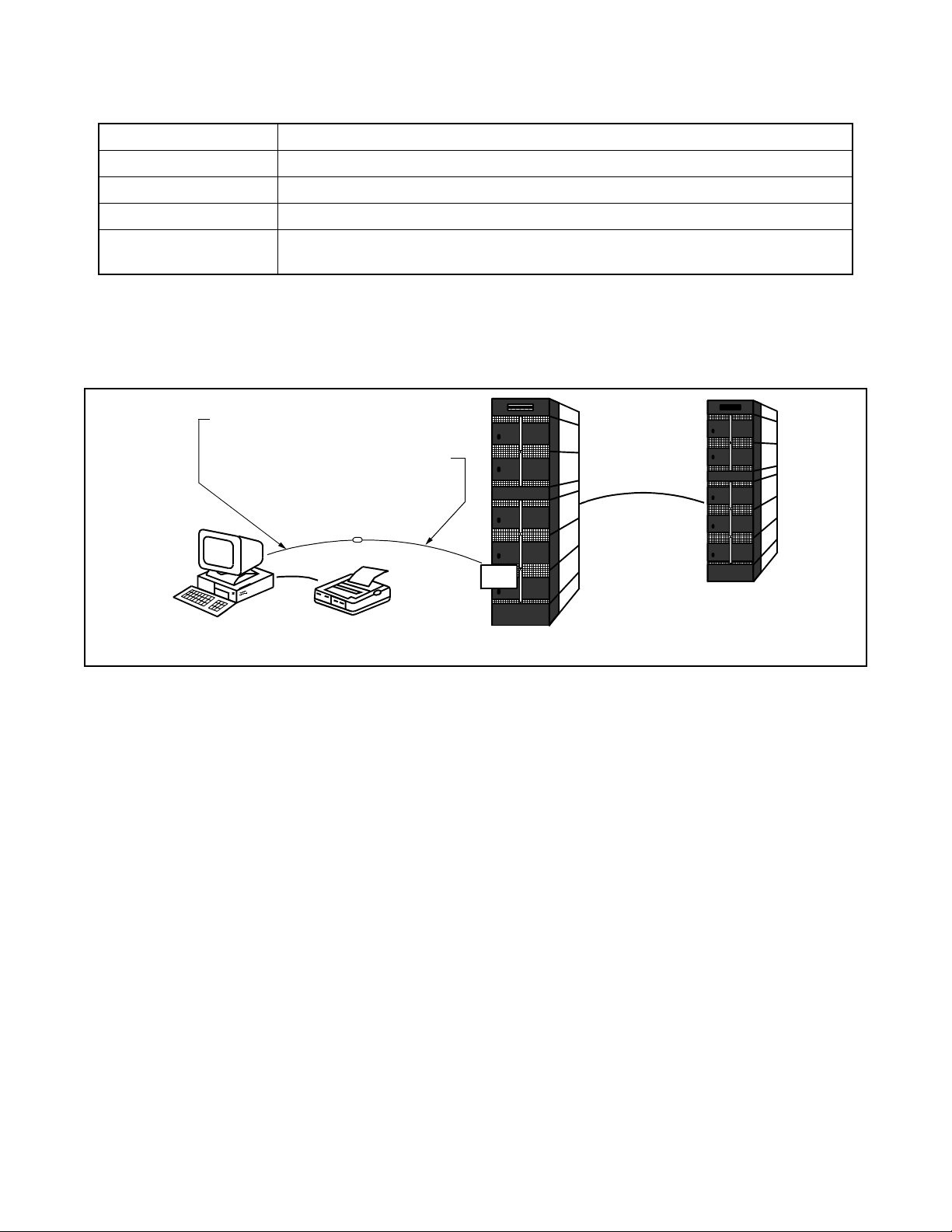
2.2 IPX MAT and IPX Connection
Figure 2-1 shows a seri al/dire ct connec tion to the IOC c ard of I PX. The serial/ direct connecti on allo ws y ou
to access the IPX and the different nodes via the Fusion Link.
NEAX 2400 TTY CABLE 1
68PH S 2 PORTS CA - A
FUSION LINK
IPX MAT
IOC
IPX MAT PRINTER
IPX
Figure 2-1 Serial/Direct Connection to IPX
IPX
IPX MAT software supports serial/direct connection to the target IPX. As seen in Figure 2-2, a modem is
required at both the remote maintenance center and the IPX site. The LINE port of the modem located at
the IPX site should be connected to the dedicated Line Circui t ( L C), and t he DATA port should be di rectly
connected to the IOC card. The serial/dialup connection allows you to access both the first node (IPX) of
the Fusion Link network and all other nodes within the Fusion Link network.
CHAPTER 2 NDA-24315
Page 4
Issue 1
Page 17
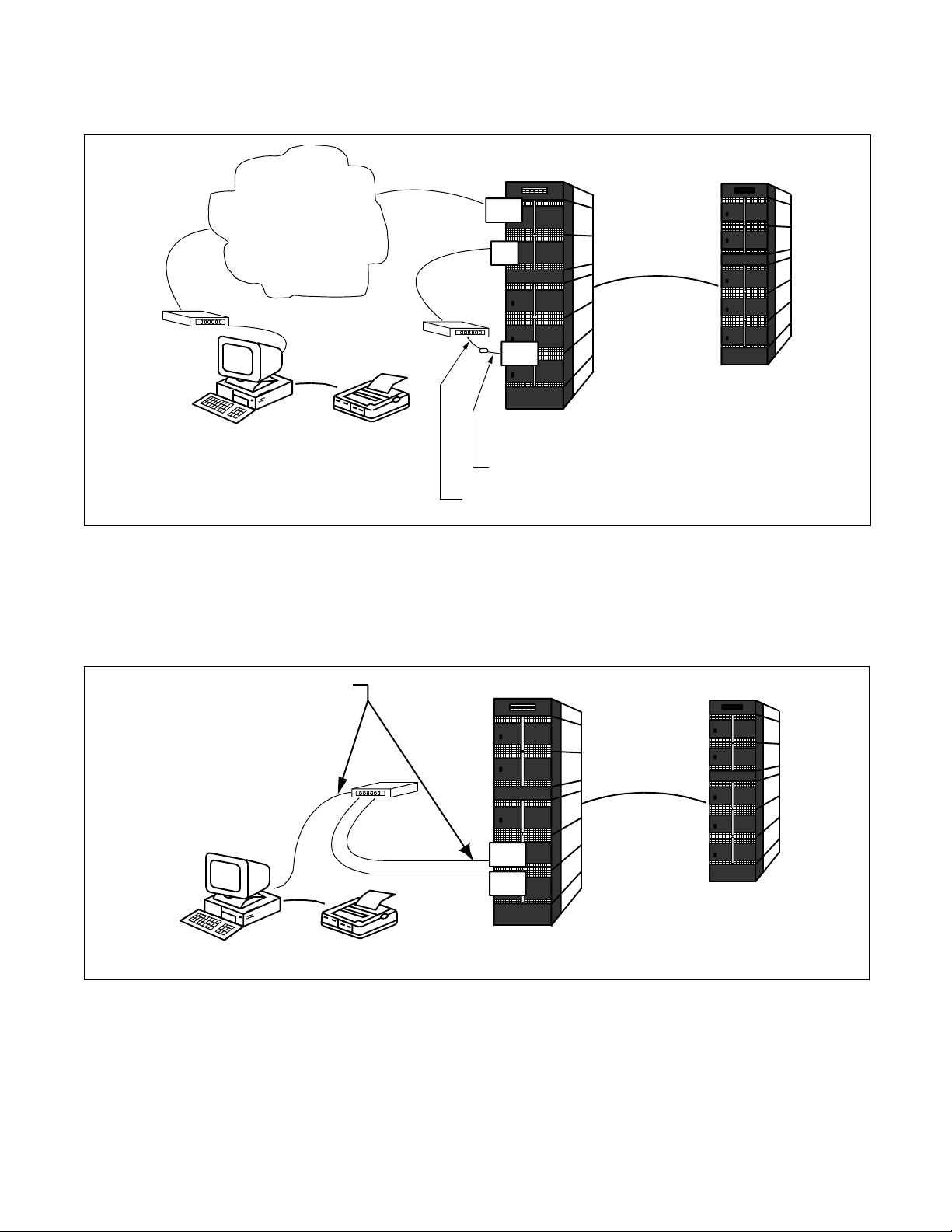
2.3 Serial/Dialup Connection to IPX
ASSIGNMENT
TELECOMMUNICATION
NETWORK
MODEM
IPX MAT
MODEM
IPX MAT PRINTER
TRK
LC
IOC
IPX
68PH S 2 PORTS CA - A
NEAX2400 TTY CABLE 3
FUSION LINK
IPX
Figure 2-2 Serial/Dialup Connection to IPX
The IPX MAT software provides an advanced communication software for IPX. IPX is maintained via th e
LAN, WAN, or TCP/IP network on which it is running. Figure 2-3 shows the simple configuration of the
TCP/IP connection. Using this con nection, an y node withi n the Fusion Link netw ork can be acces sed from
IPX MAT.
10 BASE -T straight cable
IPX MAT
Figure 2-3 TCP/IP Connection to Dual CPR of IPX
FUSION LINK
HUB
LANI
LANI
IPX
IPX
IPX MAT PRINTER
NDA-24315 CHAPTER 2
Page 5
Issue 1
Page 18
ASSIGNMENT
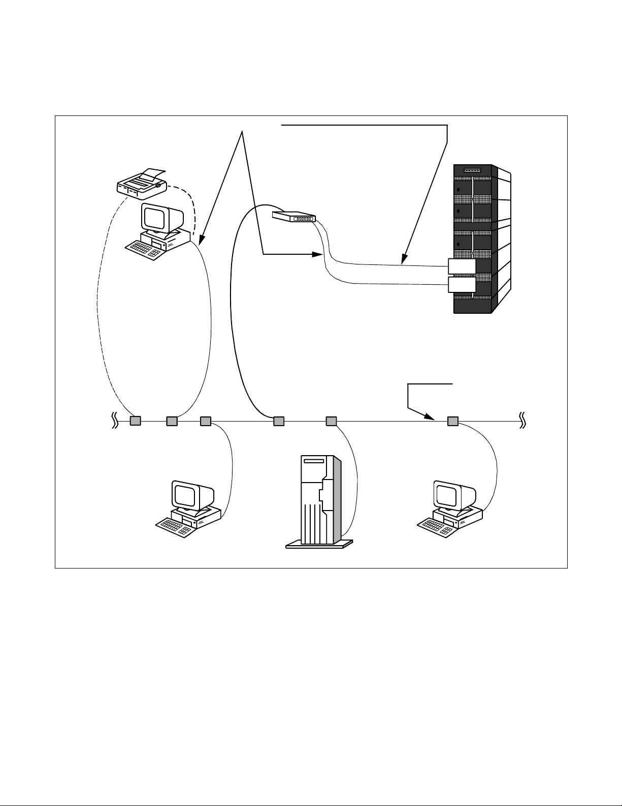
Figure 2-4 shows th e config uration of the PBX and IPX MAT when connecting to an e xisting LAN. In most
cases you should use a network de vice such a s a HUB or bridge to p rovide isol ation from e xcessi ve networ k
traffic.
10BASE-T straight cable
MAT PRINTER
HUB
MAT
PC
SERVER
LANI
LANI
IPX
LAN
PC
Figure 2-4 TCP/IP Connection (IP Address over the External LAN)
3. TCP/IP Considerations
The IPX MAT can communicat e with the IPX via an Ethe rne t TCP/IP connec tion. I n orde r for the IP X MAT t o
communicate via TCP/IP, the PC must have its net work software, i ncluding t he TCP/IP drive rs, installe d and in
operation prior to installing the IPX MAT software.
CHAPTER 2 NDA-24315
Page 6
Issue 1
Page 19
ASSIGNMENT
If the PC does not have the ne twork software installed and con figured, a messa ge indicating tha t the WINSOCK
2 setup has fai led display s during th e IPX MAT inst allation. This message i s an expect ed response since the IPX
MAT installa tion program atte mpts to upgrade the TCP/IP WINSO CK drivers to the latest version. If these
drivers are not al re ady ins tall ed, the upgrad e proce ss fail s. The f ailur e does not af fect th e succe ssful inst alla tion
and operation of the IPX MAT, but the TCP/IP interface cannot be used.
It is always best to install th e IPX MAT softwa re after all network software is inst alled. Although it is not
recommended, it is possible to install the PC’s standard network software after the IPX MAT software has been
installed. If the IPX MAT software is installed prior to installing the network software, it will be necessary to
run the WINSOCK setup program from the IPX MAT CD after installing the network software.
To run the WINSOCK setup program:
1. Insert the IPX MAT CD into the CD-ROM drive.
2. The IPX MAT setup program starts automatically.
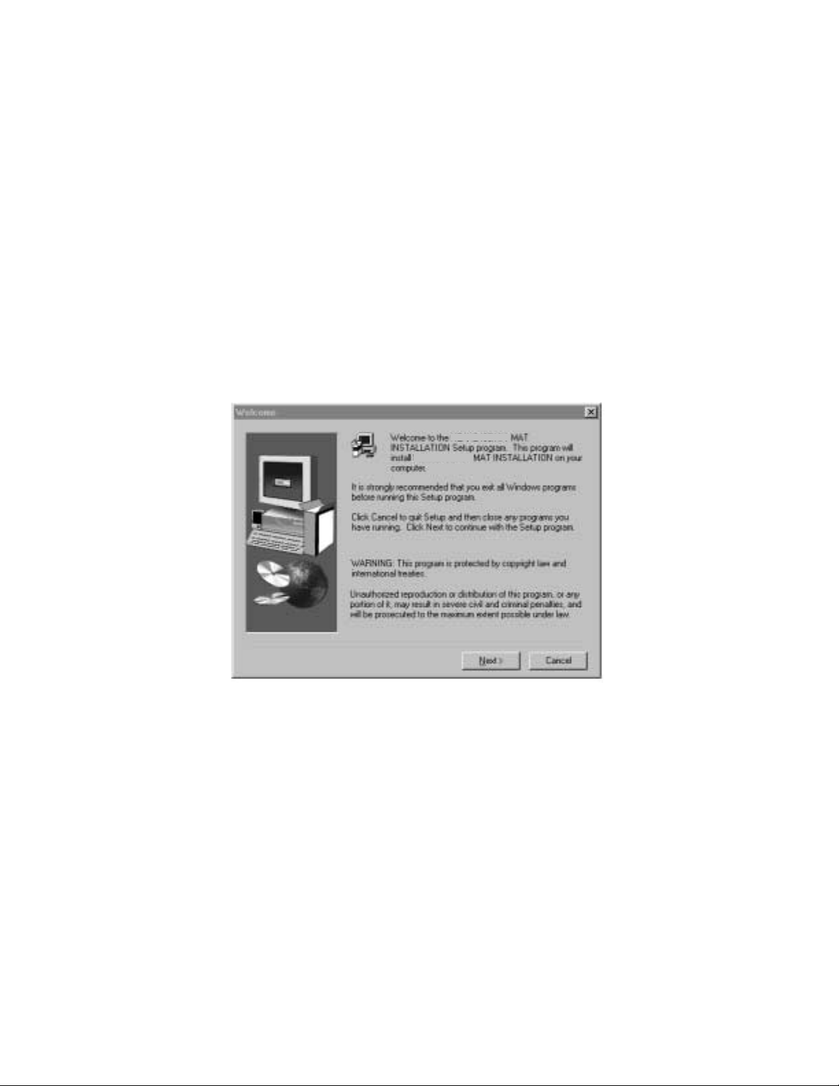
3. Terminate (Cancel) the IPX MAT setup pr ogram on the Welcome Screen.
NEAX2400IPX
NEAX2400IPX
Figure 2-5 IPX MAT Welcome Screen
4. Select the appropriate CD-ROM drive in Windows Explorer.
5. Double-click the file named WS2SETUP.EXE.
For more information about configuring TCP/IP connections, see Section 6.2, TCP/IP Connection.
4. Installing IPX MAT Software
The following provide s step-by -step i nstructions for i nstalling the IPX MAT software fo r Windows 95/NT onto
your hard disk.
1. Terminate all applications, prior to starting the installation process.
2. Insert the CD-ROM into the CD-ROM drive. (The IPX MAT installation program starts automatically .)
NDA-24315 CHAPTER 2
Page 7
Issue 1
Page 20
ASSIGNMENT
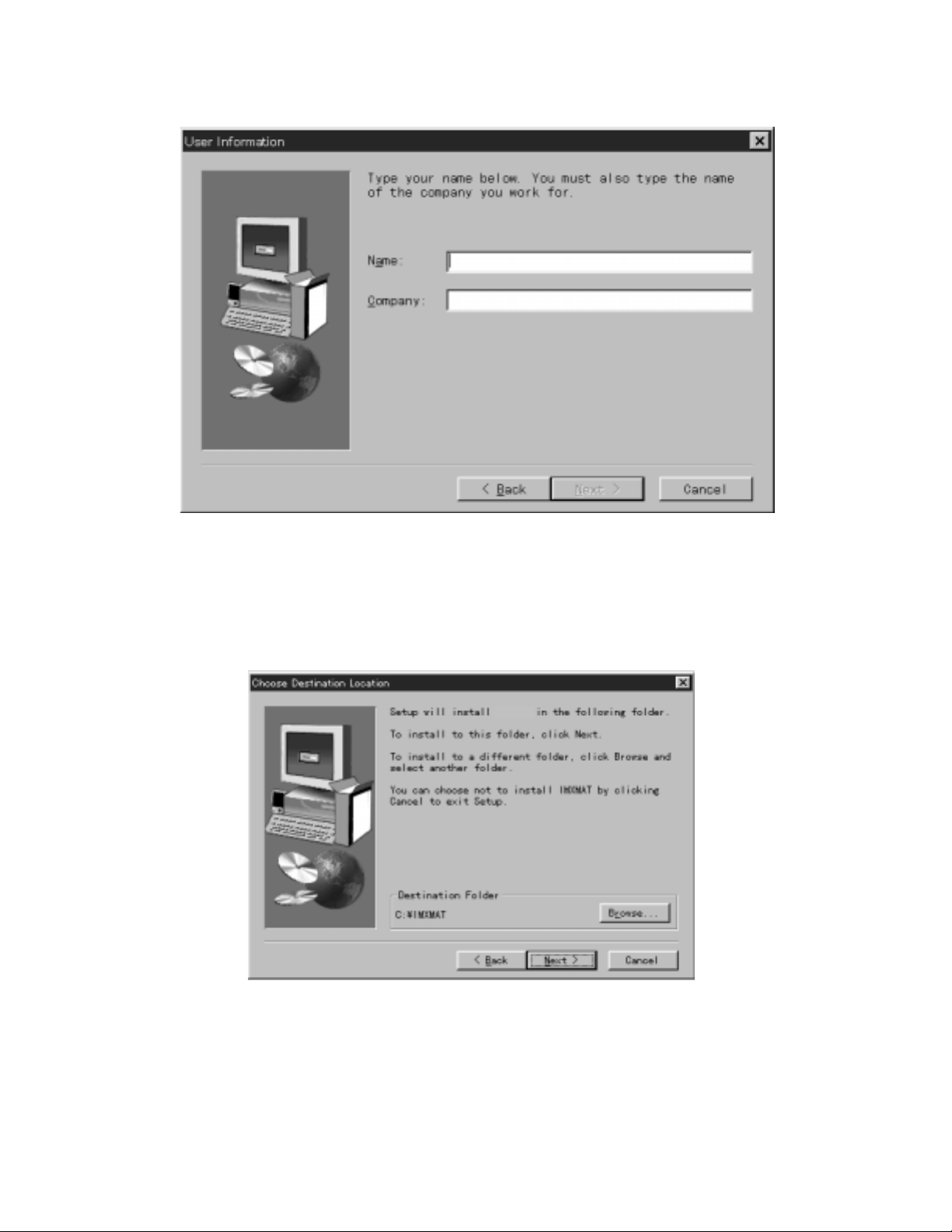
3. Enter your name and your comp a ny name on the User Information dialog box. Th en , click Next.
Figure 2-6 IPX MAT User Information Dialog
4. Click Next on the Choose Destination Location dialog box to install the IPX MAT software in the default
directory.
Note:
If you wish to install the software in another directory, you can click Browse to display a dialog box that
allows you to select or create another directory.
IPXMAT
Figure 2-7 Choose Location Destination Screen
CHAPTER 2 NDA-24315
Page 8
Issue 1
Page 21

ASSIGNMENT
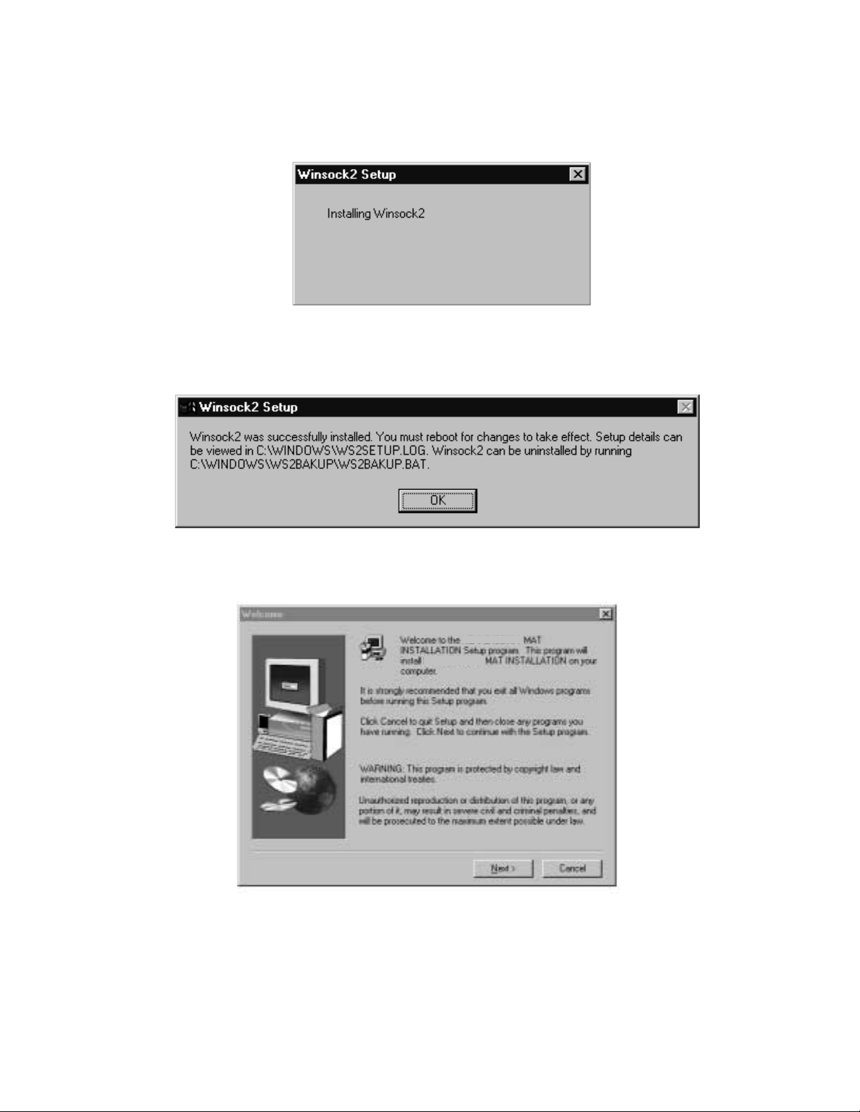
5. The dialog box, shown in Figure 2-8 (information on WINSOCK setup), appears. Click OK.
Figure 2-8 Winsock 2 Setup Message Dialog Box
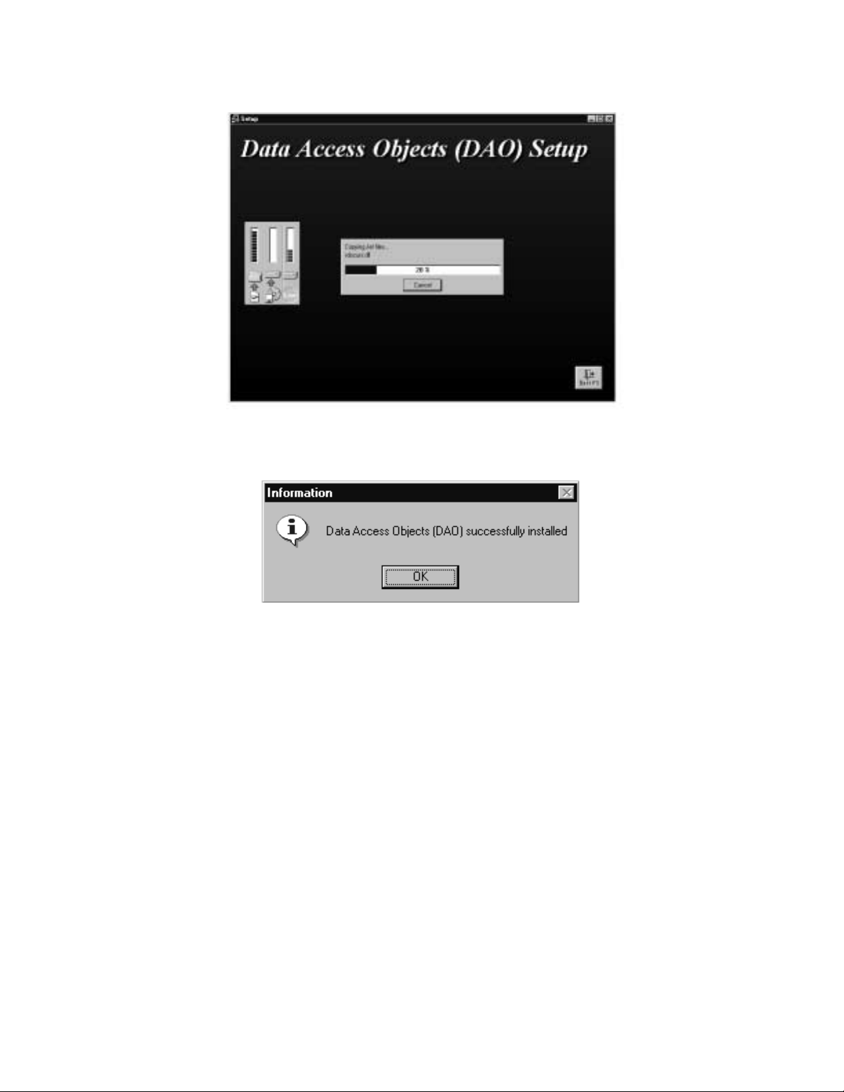
6. File copy starts automatically, while the displayed dialog boxes (See Figure 2-9) show the on-going
situation.
IPXMAT Setup
IPXMAT Installation
IPXMAT
Figure 2-9 IPX MAT Installation Screen
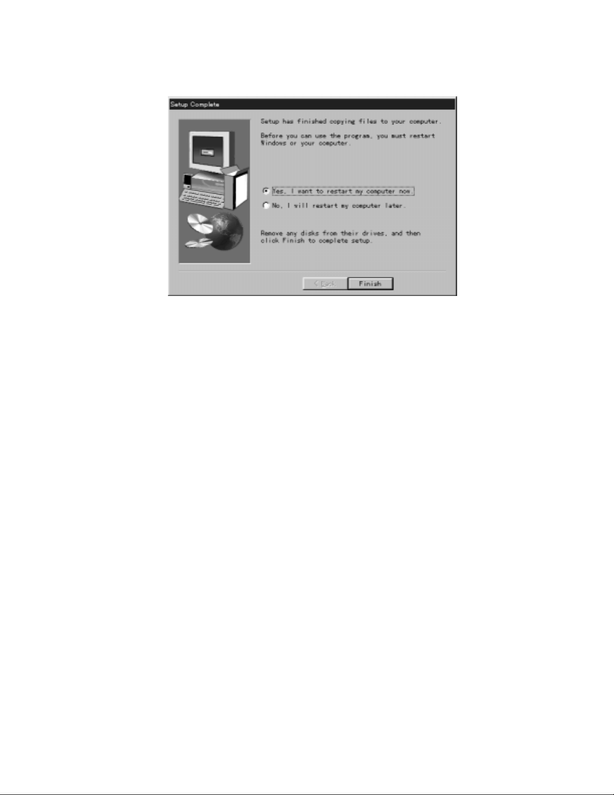
7. If the Setup Complete dialog box appears on the screen, the file copies have finished successfully. Click
Finish to complete the IPX MAT software installation and restart your computer.
NDA-24315 CHAPTER 2
Page 9
Issue 1
Page 22
ASSIGNMENT
Note:
You should always reboot your PC after inst alling the IPX MAT software. Any chang e made during the installation process does not take effect until the computer has been rebooted.
Figure 2-10 IPX MA T Setup Co mplete Dialog
CHAPTER 2 NDA-24315
Page 10
Issue 1
Page 23
ASSIGNMENT
8. Rev ie w the settings you have chosen, and then click Next. The Winsock2 Setup message box displays.
Note:
If you are install ing IPX MA T on a n NT 4.0 workstat ion, the Winsock2 Setup messag e box doe s not displ ay.
NT 4.0 does not require Winsock2 in order to run.
Figure 2-11 IPX MAT Installi ng Wins ock2 Message Box
9. After Winsock2 is installed, the Winsock2 Setup dialog box displays. This is an informational message
only. Click OK to continue installing the Data Access Objects (DAO) required to run IPX MAT.
Figure 2-12 Winsock2 Setup Message Dialog Box
10. Click OK. The DAO Welcome Screen displays.
Figure 2-13 DAO Welcome Screen
NEAX2400IPX
NEAX2400IPX
NDA-24315 CHAPTER 2
Page 11
Issue 1
Page 24
ASSIGNMENT
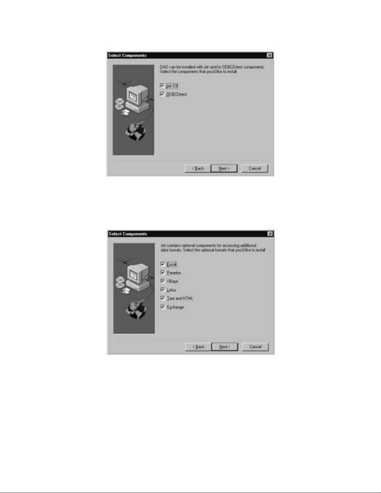
11. Click Next. The Select Components dialog box displays.
Figure 2-14 DA O Select Components Screen
12. Uncheck the ODBCDirect box and click Next. The Select Components dialog box displays.
Note:
If you do not uncheck the ODBCDirect box, error messages display once the DAO Setup program
completes. IPX MAT will run properly even though these messages display.
Figure 2-15 Select Components Screen
CHAPTER 2 NDA-24315
Page 12
Issue 1
Page 25
13. Click Next. The DAO Setup Screen displays.
Figure 2- 16 DAO Setup Screen
ASSIGNMENT
14. After the DAO files are installed, the DAO Information message box displays. Click OK. The IPX MAT
Installation screen displays.
Figure 2-17 DAO Information Message
NDA-24315 CHAPTER 2
Page 13
Issue 1
Page 26
ASSIGNMENT
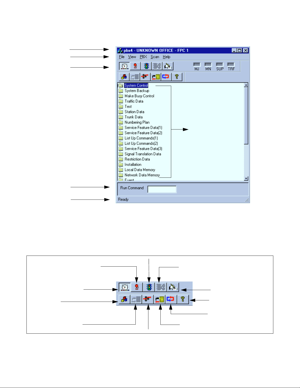
15. To run the IPX MAT software, clic k t he IPX MAT icon on the desktop or sel ect it from the Start/Program
menu. The IPX MAT menu displays as shown in Figure 2-18.
Title Bar
Menu Bar
Tool Bar
Command Folders
Enter commands here
Status Bar
Figure 2-18 IPX MAT Main Menu
16. To configure the PBX Alias, use the instructions in Section 6.2, TCP/IP Conne cti on.
Note:
Once you have configured the IPX MAT, you can use the Run Command line to enter task commands, or
you can select the command from the Command Folders. Y o u can also perfo rm IPX MA T tasks usi ng either
the menu items, or the icons equivalent to the menu items.
Collect New Traffic
Collect New Alarms
Scan New Alarms/Traffic
Processes
Log On
Configure
Abort Data Collection
Log Out
View Scanning Log
About
Log Manager
Figure 2-19 IPX MAT Tool Bar
CHAPTER 2 NDA-24315
Page 14
Issue 1
Page 27

ASSIGNMENT
5. IPX MAT Commands
The IPX MAT’s operation is very similar to that of the NEAX2400 MS-DOS MAT, so you will find that many
of the key stroke operations have been carried over into IPX MAT. In addition, some standard MS Windows
operations and key strokes are used. Use the following keys, or in some instances the mouse, to select or enter
data.
Table 2-2 IPX MAT Commands
This key has two functions:
Enter and Tab
Y (y) Enter Y in the WRT? text control to write the data to the IPX.
N (n) Enter N in the WRT? text control if you do not want to write the data to the IPX.
Delete Deletes the selected characters in a text control.
Backspace Deletes the character immediately to the left of the cursor in a text control.
Right Arrow Moves the cursor to the right in the text control.
Left Arrow Moves the cursor to the left in the text control.
Up Arrow Moves the cursor to the left in the text control.
Down Arrow Moves the cursor to the right in the text control.
Alt + F4 Closes the screen without saving the changes.
Shift + Enter and Shift + Tab Moves the cursor from a text control to the previous text control.
Ctrl + C Copies selected text to Windows Clipboard.
Ctrl + V P a st es Windows Clipboard contents at the current cursor position.
Ctrl + Home
(When viewing the log file).
Ctrl + End
(When viewing the log file).
Page Up
(When viewing the log file).
Page Down
(When viewing the log file).
? or F1 Displays the Help text.
Writes the data to the IPX MAT memory and moves the cursor to the next text control
on the dialog window.
Moves the cursor to the top of the log data file.
Moves the cursor to the bottom of the log data file.
Moves the log file up one page at a time.
Moves the log file down one page at a time.
6. Configuring IPX MAT
This section explains the PBX Alias parameters you may configure using the PBX Administration dialog
window. It also lists the default values of NEAX-IPX, the default PBX Alias delivered with the IPX MAT
software. Prior to running the IPX MAT, you shoul d eithe r define a new PBX Alias , configure the default PBX
to work with your system, or pla n to use the NEAX-IPX def ault Alias. NEAX-IPX is ready for use once the IPX
MAT software has been successfully installed. Table 2-3 lists the default values displayed in the PBX
Administration dialog box when you select NEAX-IPX as your PBX Alias.
NDA-24315 CHAPTER 2
Page 15
Issue 1
Page 28

ASSIGNMENT
Table 2-3 PBX Administration Default V alues
PBX Alias NEAX-IPX
Connection Type Serial/Direct
FPC 1
Connect 120000
Response Timeout 120000
Pacing Timer 10000
Link Data Log Path blank
COM Port COM 1
Baud Rate 4800
Ignore CTR blank
Ignore DSR blank
Modem Name blank
Phone Number blank
Host Name blank
IP Address 172.16.253.0
TCP Port 60000
Inter-App Resource blank
6.1 Serial/Direct Connection
The following steps explain how to configure the PBX Alias for a serial/direct connection using the
recommended def aul t dat a.
Note 1:
Note 2:
The PBX Alias cannot have spaces in the name.
You can use other data when configuring IPX MAT. However, it is recommended that you use the default
data as previously described when configuring a new PBX Alias.
CHAPTER 2 NDA-24315
Page 16
Issue 1
Page 29
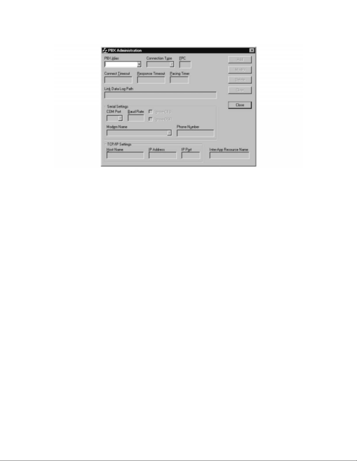
1. From the PBX menu, select Configuration to open the PBX Administration dialog box.
Figure 2-20 PBX Administration
2. Enter a name for the PBX Alias in the PBX Al ia s box.
ASSIGNMENT
Note:
You can also define a PBX Alias by selecting the default NEXT-IPX or by modifying any other previously
defined Alias from the list in the PBX Alias box. If you select a PBX Alias from the list, its related
information displays in the additional fields on this dialog box. You can enter information in the Connect
Timeout, Response Timeout, Pacing Timer, and Link Data Log Path fields if necessary. However, the IPX
MAT software will run without changing the default data.
3. Select Serial/Direct as the Connection Type.
4. Enter the appropr iate FPC (Fusi on Link P oint Cod e) . 1 is t he def aul t v a lue and sh ould be used i nitia lly
for all new IPX sy st ems. In a Fus ion Netw ork, t his se ttin g must match the FPC value entered into System Data SYS 1 INDEX 512.
5. Enter 120000 in the Connection Timeout text box.
6. Enter 120000 in the Response Timeout text box.
7. Enter 10000 in the Pacing Timer text box.
8. Clear (Remove) a ny text from the Link Data Log Path text control.
9. Set COM1 Baud rate to 4800. This is the default PBX value on the initial power up.
10. Leave the Host Name text box blank.
11. Leave the IP Address text box blank.
12. Leave the IP Port text box blank.
13. Leave the Inte r-Ap p Resource text bo x blank.
NDA-24315 CHAPTER 2
Page 17
Issue 1
Page 30
ASSIGNMENT
14. Click Add to write the data.
15. Click Close.
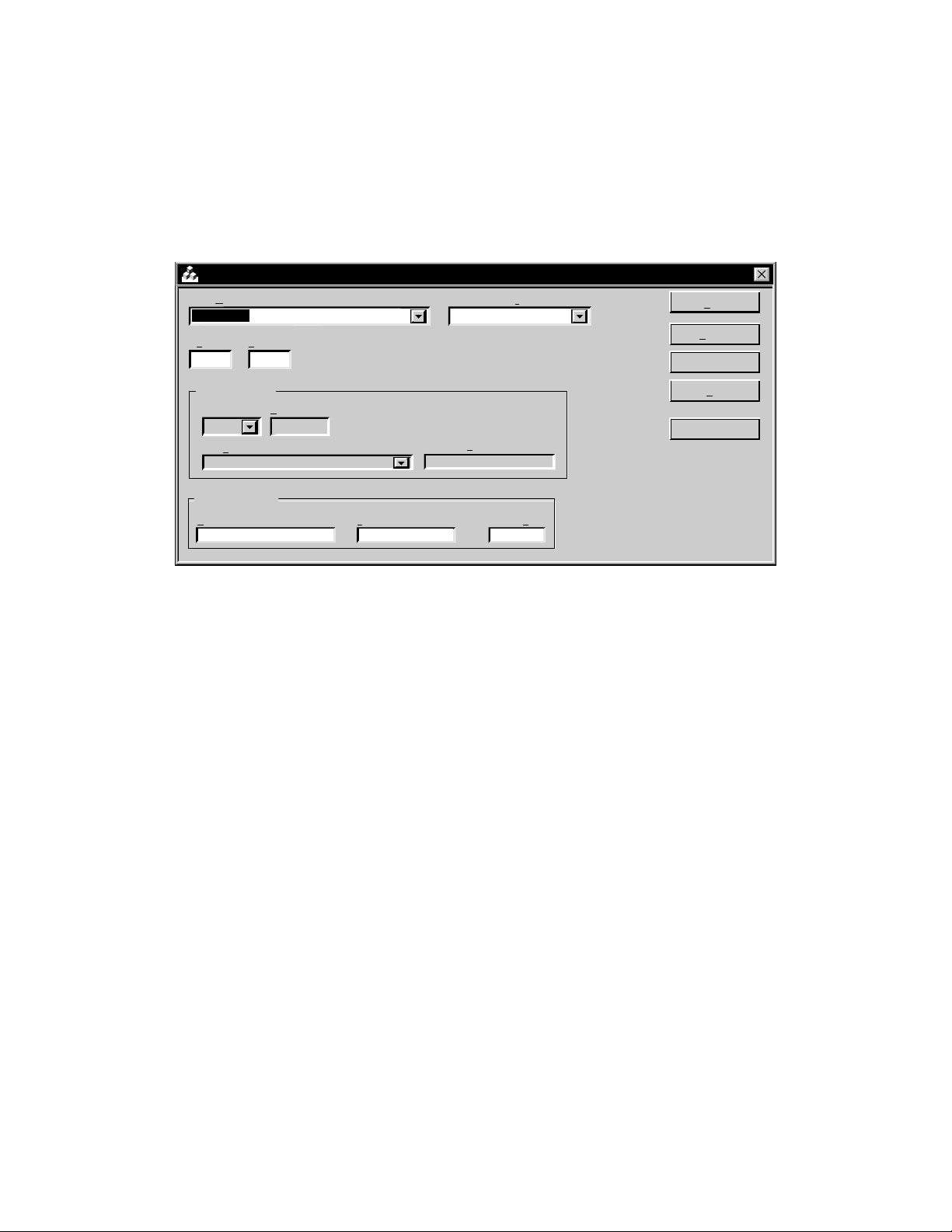
Note:
The PBX Administration dialog box changes adapting to EX-FCCS Network. Enter the Fusion Group
Number (FUG) which the PBX to be logged-in belongs. “Connection T imeout ”, “Respo nse Timeout”, and
“Pacing Timer” text box is not provided. Others are the same as previous one. The PBX dialog box is as
shown below.
PBX Administration
PBX Alias
TCP-IP134
FUG
3
Serial Settings
COM Port
Modem Name
TCP/IP Settings
Host Name
bsc7200
6.2 TCP/IP Connection
This section explai ns ho w to add or modi fy a PBX Alias in IPX MAT when it is connected to a PBX using
a TCP/IP connection through a Local Area Network (LAN).
FPC
1
Baud Rate
Connection Type
TCP/IP
Phone Number
IP Address TCP Port
10.41.207.207 60000
Add
Add
Modify
Modify
Delete
Clear
Close
Procedure Overview
1. Modify or add a PBX Alias.
2. Assign the network information in Windows.
3. Start the PBX system.
4. Log in to IPX MAT.
5. Assign the system data.
6. Set up the IPX MAT file operations for logging purposes.
Note:
If your IPX is to reside on your existing LAN, you will need to obtain an available IP address from your
System Administrator before you configure the PBX Alias.
6.2.1 Modifying or Adding a PBX Alias
Note:
CHAPTER 2 NDA-24315
Page 18
Issue 1
The PBX Alias cannot have spaces i n its name.
Page 31

ASSIGNMENT
The following steps explain how to create a PBX Alias in IPX MAT.
1. From the PBX menu, select Configuration to open the PBX Administration dialog box.
2. Enter a name for the PBX Alias in the PBX Al ia s box.
Note:
You ca n also define a PBX Alias by se lecting the de fault NEXT-PBX or by modifying any other previously
defined Alias from the list in the PBX Alias box. If you select a PBX Alias from the list, its related
information displays in the additional fields on this dialog box. You can enter information in the Connect
Timeout, Response Timeout, Pacing Timer, and Link Data Log Path fields if necessary.
3. Select TCP/IP as the Connectio n Type.
4. Enter the appropriate FPC (Fusion Link Point Code). 1 is the default value and should be used
initially for all new IPX systems. In a Fusion Network, this setting must follow the FPC value
entered into System Data SYS 1 INDEX 512.
5. Enter 120000 in the Connection Timeout text box.
6. Enter 120000 in the Response Timeout text box.
7. Enter 10000 in the Pacing Timer text box.
8. Leave the Link Data Log Path text box blank.
9. Enter the name of the host your system is using in the Host Name text box.
10. Enter 172.16.253.0 in the IP Address text box, or enter the IP Address supplied by your network
administrator.
11. Enter 60000 in the IP Port text box.
12. Leave the Inte r-Ap p Resource text bo x blank.
13. Click Add to write the data.
14. Click Close.
15. Exit IPX MAT.
6.2.2 Ass i g ning Network Information in Wind ow s
Before you can run the IPX MAT software, you have to configure your network information in the
Windo ws operat ing system. For informati on on configur ing network information, see the Network Cir cuit
Card Installation Manual or tal k to your network administrat or . After configu ring the network inform ation,
you must restart the PC before you can log in to the IPX via the IPX MAT TCP/IP connection.
6.2.3 Starting the PBX System
Before you can log in to t he PBX with your IPX MAT, you must start the PBX system. To start the PBX
system, please see the NEAX2400 IPX Installa ti on Manual .
NDA-24315 CHAPTER 2
Page 19
Issue 1
Page 32

ASSIGNMENT
If you start up the system when the PBX is in DM Clear Restart mode, (the SENSE Switch is set to the
default value “1”), you must verify that the IPX MAT baud rate is set to 4800 to ensure that the system
runs properly.
6.2.4 Logging in to IPX
After you have defined the PBX Alias in IPX MAT and the TCP/IP network connection in Windows,
you are ready to Log in to IPX. The Login operation allows you to select the target IPX (node) with
which you are attempting to communicate. Once you log in to IPX, you may assign or delete of fice dat a,
monitor the status of IP X, obtain System Messa ges through the IPX’s self-diagnosis function, an d monitor the IPX traf f ic and Peg c ount data. On ce you ha ve complet ed the tasks yo u intended to pe rform, you
should log out to prevent accidental changes to the data. The following steps explain how to log in to
IPX.
Note:
The maximum number of concurrent connections for the IPX is four.
1. From the IPX menu, select Log In.
2. Select the PBX you want to connect to by choosin g the appr opriate PBX Alias from the PBX Ali as
box.
Note:
When the User ID data is pr o gra mmed in A UIDN comman d after the r equ ir ed off ice da ta assignment, ente r
the proper user name and password to login to the NCN.
3. Click Login.
4. A successful log in displays the successful Login message box.
Note:
If the Login messa ge box doe s not display, the login pr ocess has f ailed. If th e login pr ocess fai ls, you should
reopen the PBX Configuration dialog box and verify the PBX Alias configuration information. If the PBX
Alias has been correctly configured, you should then test the physical connections to the PBX.
5. Click OK on the Login message box.
6.2.5 Assigning System Data
This section explains how to assign the IP Address and the SubNet Mask using the default IP Address
172.16.253.0 and the default SubNet Mask 00.00.00.00. Both fields must be entered using their
hexadecimal equivalents.
Note:
You may find it convenient to use the Calculator in the Windows Accessories to find the hexadecimal
equivalent of the IP Address and the SubNet Mask. To convert from decimal to hexadecimal:
1. Select Calculator fro m the Accessories menu.
2. From the View menu, select Sc ientific.
3. Verify that Dec is selected.
4. Click the first three numbers of the IP Address on the Calculator key pad.
5. Select Hex.
6. The hexadecimal equivalent of the first three numbers of the IP Address display.
CHAPTER 2 NDA-24315
Page 20
Issue 1
Page 33

7. To perform additional decimal to he xa dec imal conversions, make sur e that De c is se lecte d
and repeat the previous steps.
1. Type ASYDL in the Run Command text box.
2. Press Enter.
3. Type 1 in the SYS text box and press Enter.
4. Type 513 in the INDEX text box and press Enter.
5. Type 01H in the DATA text box and press Enter.
6. Type Y in the WRT? text box and press Enter.
7. Type 1 in the SYS text box and press Enter.
8. Type 514 in the INDEX text box and press Enter.
9. Type 01H in the DATA text box and press Enter.
10. Type Y in the WRT? text box and press Enter.
ASSIGNMENT
Note:
The following steps explain how to assign the default IP Address.
11. Type 1 in the SYS text box and press Enter.
12. Type 515 in the INDEX text box and press Enter.
13. Type AC (hexadecimal equivalent of 172) in the DATA text box and press Enter.
14. Type Y in the WRT? text box and press Enter.
15. Type 1 in the SYS text box and press Enter.
16. Type 516 in the INDEX text box and press Enter.
17. Type 10 (hexadecimal equivalent of 16) in the DATA text box and press Enter.
18. Type Y in the WRT? text box and press Enter.
19. Type 1 in the SYS text box and press Enter.
20. Type 517 in the INDEX text box and press Enter.
21. Type FD (hexadecimal equivalent of 253) in the DATA text box and pr ess Enter.
22. Type Y in the WRT? text box and press Enter.
23. Type 1 in the SYS text box and press Enter.
24. Type 518 in the INDEX text box and press Enter.
25. Type 0 (hexadecimal equi valent of 0) in the DATA text box and press Enter.
NDA-24315 CHAPTER 2
Page 21
Issue 1
Page 34

ASSIGNMENT
26. Type Y in the WRT? text box and press Enter.
Note:
The following steps explain how to assign the default SubNet Mask.
27. Type 1 in the SYS text box and press Enter.
28. Type 519 in the INDEX text box and press Enter.
29. Type FF in the DATA text box and press Enter.
30. Type Y in the WRT? text box and press Enter.
31. Type 1 in the SYS text box and press Enter.
32. Type 520 in the INDEX text box and press Enter.
33. Type FF in the DATA text box and press Enter.
34. Type Y in the WRT? text box and press Enter.
35. Type 1 in the SYS text box and press Enter.
36. Type 521 in the INDEX text box and press Enter.
37. Type 00 in the DATA text box and press Enter.
38. Type Y in the WRT? text box and press Enter.
39. Type 1 in the SYS text box and press Enter.
40. Type 522 in the INDEX text box and press Enter.
41. Type 00 in the DATA text box and press Enter.
42. Type Y in the WRT? text box and press Enter.
6.2.6 IPX MAT File Operations
The IPX MAT creates three types of files; Command Log files, Office Data Backup files, and List-up
Command Report data table s. Command Log f iles and List-up Command Report data t ables are the onl y
files a user needs to v ie w. The Off ice Data Bac kup f i les ar e u sed st rict ly for sa vin g an d stor ing th e PBX
Offi ce Data.
6.2.6.1 Office Data Backup
It is alw ays a good idea to routin ely bac kup the da ta from t he IPX memo ry to it s inter nal hard disk. Thi s
data should then be saved from the IPX internal hard disk to the IPX MAT hard disk to ensure that no
data is lost.
CHAPTER 2 NDA-24315
Page 22
Issue 1
Page 35

ASSIGNMENT
Once the data has been sa ved from the IPX internal hard disk to the IPX MAT’s hard disk, you can use
standard operating functions to copy the saved data to floppy disks, zip drive disks, writable CD-ROM
drives, or any other type of external storage devices supported by the operating system. Doing a three
phase backup (save) ensures the IPX Office data is safe and always available for restoration in case of
an IPX data memory loss, hard disk failure, or any other IPX-related catastrophic failure that requires
data memory to be rel o aded.
MEM_HDD and HDD_MAT are the tw o commands used for thi s three-phase backup. Once t he data is
saved to the IPX MAT, you can use Explorer to copy the appropriate files to the external mass storage
device. To use Explorer, you must first de termine wh ere the IPX MAT cop y of t he numerous IPX Of f ice
Data backup files resides.
As an example, assume the default drive and directory C:\IPXMAT were used when IPX MAT was
installed. Also assume that a PBX Alias was configured using the PBX Configuration dialog and
assigned the PBX Alias name MY_PBX.
The IPX MAT always uses the sa me data dire ctory str ucture when backi ng up data fro m the IPX. It cre ates a sub-directory under the IPX MAT home directory called DATA. Under the DATA directory another sub-directory using the PBX Alias name is created. In our example, this sub-directory is named
MY_PBX. Under the PBX Alias director y, another sub-directory i s c re at ed. The name of this director y
is BA CKUP. This di rectory struc ture alwa ys holds true. The o nly v ariables are the name of the IPX MAT
home directory (default C:\IPXMAT) and the PBX Alias directory (in our example, MY_PBX). The
complete directory structure for our example is as follows: C:\IPXMAT\DATA\MY_PBX\BACKUP.
The bottom sub-director y (B A CKUP) conta ins all f iles that ha ve b een backed up f rom the IPX using th e
HDD_MAT command.
To save these fi les to an external storage device, open Explorer, navigate to the appropriate backup
directory (C:\IPXMAT\DATA\MY_PBX\BACKUP) and select ALL files and/or sub-directories and
copy them to your external device. You now have a safe backup of your IPX data memory that can be
stored at an offsite location.
6.2.6.2 MEM_HDD
The following ste ps e xplai n ho w to perform the backu p and rest ore of PBX data to the PBX hard drive.
1. Enter MEM_HDD in the Run Com m a nd field on the IPX MAT m ain menu.
2. Press Enter.
3. The Backup and Restore dialog box displays.
4. Select Memory to Hard Disk in the Direction Select list .
5. Select Data Memory in the Data Type Selection list.
6. Select Auto Verify if you want to verify the data. This is an optional step.
7. Click Start.
NDA-24315 CHAPTER 2
Page 23
Issue 1
Page 36

ASSIGNMENT
Once you have made the appropriat e selections and cl icked Start , you can scroll do wn and vie w the dat a
being sav ed in the Processing Statu s Log windo w . Th is section o f the windo w is di vided into t he sections
Action/Information, Direc tion, Data Type, and Time Stamp. The Action/Infor mation column sho ws th e
Action being taken (saving or restoring), or the Information being saved. The Direction column shows
where the data is being saved or restored (in this case, memory to PBX Hard Disk). The Data Type
column shows the type of data you selected in the Data Type Selection list. The Time Stamp column
shows the day, month, year, hour, minute, and second the data was backed up or restored.
6.2.6.3 HDD_MAT
The follo wing steps explain how to backup and restore PBX data to the IPX MAT hard disk.
1. Enter HDD_MAT in the Run Command field on the IPX MAT main menu.
2. Press Enter.
3. The Backup and Restore dialog box displays.
4. Select PBX Hard Disk to MAT in the Direction Select list.
5. Select Data Memory in the Data Type Selection list.
6. Select Auto Verify if you want to verify the data. This is an optional step.
7. Click Start.
Once you have made the appropriat e selections and cl icked Start , you can scroll do wn and vie w the dat a
being sav ed in the Processing Statu s Log windo w . Th is section o f the windo w is di vided into t he sections
Action/Information, Direc tion, Data Type, and Time Stamp. The Action/Infor mation column sho ws th e
Action being taken (saving or restoring), or the Information being saved. The Direction column shows
where the data is being saved or restored (in this case PBX Hard Disk to IPX MAT). The Data Type
column shows the type of data you selected in the Data Type Selection list. The Time Stamp column
shows the day, month, year, hour, minute, and second the data was backed up or restored.
6.2.6.4 List-up Command Report Data Tables
These data file s are tables assembled into an MS-Access Database f ormat. The List-up commands cre ate
the database and tables, populating them based on the information specified by the user. After the
database and tabl es are creat ed, the repor t that auto maticall y find s the correc t data table and prese nts the
stored data in a format suitable for viewing is launched. These data tables are cleared and repopula ted
each time the corresponding List-up command is run. These data tables require no user intervention.
6.2.6.5 Command Log Files
These files are simple text files that capture the results of the operations performed by every IPX MAT
command. These log files are functionally equivalent to the printed output log created by the old MSDOS MAT. The only difference is that these text files can easily be viewed from within any IPX MAT
command at any time so it is not necessary to have a printer available. These log files are also easy to
print if a printer is available.
CHAPTER 2 NDA-24315
Page 24
Issue 1
Page 37

The log file maintains a history trail of operations and actions requested by the user. This log file
continues to gro w as each command is run and in terac tions with the IPX PBX are tr ansact ed. It doesn’t
matter whether the operation is a query, a change, a create, or a delete, the operation, its data, and its
status will always be logged (added to this log file).
The log file can be viewed any time by s el ecting it from the comma nd’s view menu selection. Once the
log file viewing window is opened, the log file can be printed by selecting the print option from its Fil e
menu selection. Pressing the CTRL+END key combination will quickly take you to the end of the file
where the latest changes have been appended.
Since the log file continually grows, you should regularly delete this file to conserve disk space. It also
makes the file much more manageable and useful if it is not full of log entries that are no longer of
interest. To delete and otherwise manage this file, the IPX MAT main menu contains menu selections
that will prese nt a log file maintena nce dialog. From here, the log file ca n be easily delete d.
6.2.6.6 Viewing the Log Data File
To view the log data file:
1. Display the Backup and Restore dialog box.
ASSIGNMENT
2. Select Operation Log from the View menu.
3. The log file File Viewer window displays.
6.2.6.7 Printing the Log Data File
To print the log data file:
1. Display the log f ile in the FileViewer window.
2. Select Print from the File me nu.
6.2.6.8 Copying Data from the Log File
To copy data from the log file:
1. Display the log f ile in the FileViewer window.
2. Highlight the data you want to copy.
3. Select Copy from the Edit menu.
6.2.6.9 Pasting Log File Data
To paste log file data int o another text ed iting tool:
Note:
1. Open the text editing tool you want to paste the data into.
2. Select paste from the Edit menu.
You cannot paste copied data from one location to another in the log file. The log file is a Read-Only file .
NDA-24315 CHAPTER 2
Page 25
Issue 1
Page 38

ASSIGNMENT
7. Data Assignment Flow Chart
This section shows the data assignment flow chart for IPX. The standard data assignment is illustrated on the
following flow charts.
• Local Node/Stand Alone
• Network Control Node
• Hotel Command
7.1 Local Node/Stand Alone
The follo wing fl o w c hart s ho w s the d ata as signment for MAT wh en oper ated i n a Local Node/St and Alon e
environment.
1. Local Node/Stand Alone
ATIMSystem Base ASYD ASYDL AUNT AIOC ASTD AOFC
Sys1 Index 0 - 511 , Sys2 Index 0 - 15 & Sys3 Index 0 - 31
Sys1 Index 512 - 1535
Numbering Plan
Network Numbering
Restriction
ANPD ASPA
ANPDL ASPAL
Timing Start is available
2nd DT :
:
Sender
LCR / LCRS :
Uniform Numbering :
Incoming :
Trunk:
ARSC ARRC ATDP AARP APCR AEFR
STN
SRV
SSC/SSCA, etc.
SSC
OGC(A)/LCR(S)
SRV
TELN
AMND ARNP
ANND ASTP AOSP ARNP
ASTPL AOSPL
ACMO ATCP AFRS AOPR AADC
AMND ARNP
AUNE AMND
AUNEL
ALDN ASTP AISP ARAC
ASTPL AISPL
Station Number
Service / Network
Operator Call / OGQ / Priority Call
Outgoing Call
Telephone Number available in the Self node only
AFRSL AOPRL AADCL
ASDC
ATDPL AARPL
Service:
ASFC ACFR ATNR AABD
Figure 2-21 Local Node/Stand Alone Data Flow Assignment Flow Chart (1/2)
CHAPTER 2 NDA-24315
Page 26
Issue 1
Page 39

Station Number
(Physical STA No.)
For Telephone Number:
For Station:
ASDT ASTN APHN APHNL ANDD
ASCL
(Calling available in the self node only)
ALGSL
ASSIGNMENT
For Dterm SeriesE:
For Service:
For Hot Line:
For Data:
Trunk ATRK MBTK AMAT ASAT ATGL AAKP
Service
Internal Trunk
External Trunk
AKYD AFDD ADSL ADKS ADRTL
AICD ADIM
See
AHLS ASPD
ADA2 AFCD
Station:
ASHP ASHC ASHU AUCD AUOG AUAD ACPG ACPE
ASHPL ASHCL
AISA AISD ASGD ASID ACFS ASLU1 ASLU2
PSTN :
ACSA ACSI ANCD ATAS AEKD AAND AANDE
Service
ATT :
ORT / IRT / SND / CFT:
ARTD ATRK MBTK
AIZP
ATRK MBTK
PSTN :
TIE LINE :
DAT :
CCIS No.7 :
ISDN :
ACOC
APAD
AAED
ADPC
ADPCL ACSCL
ADPC ACSC
ACID
AAEDL
AHMS
ACSC
ACIC1
ACPGL ACPEL
ACIC1
ACIC2 ARTI
ARTI
ACSAL ACSIL
Others:
ASPD AATC ACFO
CCIS No. 7
ISDN
Service:
Service:
ARPC ARDN
ACDD ACNP ACND AFCP ACBC AVTC AVTL
Figure 2-21 Local Node/Stand Alone Data Assignment Flow Chart (2/2)
NDA-24315 CHAPTER 2
AEVT
Page 27
Issue 1
Page 40

ASSIGNMENT
2. Network Control Node
Numbering Plan
Fusion Network
Numbering Plan:
Network Numbering
ATIMSystem Base ASYD ASYDL ASYDN AUNT AIOC ASTD AOFC
Sys1 Index 0 - 1535
Station Number
Service / Network
Operator Call / OGQ / Priority Call
Outgoing Call
Telephone Number available in the
Self node only
Operator Call / Call Pickup Group / OGQ / Priority Call
Call Pickup Expand / UCD BUSY OUT
Outgoing Call
Telephone Number available in all
nodes of Fusion Network
ASTPL AOSPL
ASTPN AOSPN
AFRSL AOPRL AADCL
AFRSN AOPRN AADCN
AMND
ANPD ASPA
ANPDL ASPAL
ANPDN ASPAN
Timing Start is available
2nd DT :
Sender :
LCR / LCRS :
Uniform Numbering :
Sys1 Index 0 - 511 , Sys2 Index 0 - 15 & Sys3 Index 0 - 31
SRV
SRV
SRV
Sys1 Index 512 - 1535
STN
SSC/SSCA, etc.
SSC
OGC(A)/LCR(S)
TELN
SSC
SSCA
OGC(A)/LCR(S)
TELN
AMND ARNP
ANND ASTP AOSP ARNP
ACMO ATCP AFRS AOPR AADC ASDC
AMND ARNP
AUNE
AFMU ALRTN
AUIDN
AUNEL
Restriction
Incoming :
Trunk:
Service:
ARSC ARRC ATDP
ARSCN ARRCN
ASFC
ALDN ASTP AISP ARAC
ASTPL AISPL
ASTPN AISPN
AARP
ATDPL AARPL
ATDPN
ACFR ATNR AABD
AARPN
APCR AEFR
Figure 2-22 Network Control Node Data Assignment Flow Chart (1/2)
CHAPTER 2 NDA-24315
Page 28
Issue 1
Page 41

Station Number
For Telephone Number:
(Physical STA No.)
For Station:
ASDT ASTN APHN APHNL APHNN ANDD
ASCL
ALGSL
ALGSN ATSTN
(Available in the self node only)
(Available in all nodes of the Fusion network.)
ASSIGNMENT
For Dterm SeriesE:
For Service:
For Hot Line:
For Data:
Trunk ATRK MBTK AMAT ASAT ATGL AAKP
Fusion Link
Service
Internal Trunk ATT
External Trunk
AKYD AFDD ADSL ADKS ADRTN
AICD ADIM
See
FCCH:
Ether:
Station:
ASHPL ASHCL ACPGL ACPEL
Service
AHLS ASPD
ADA2 AFCD
:
ORT / IRT / SND / CFT:
ARTD ATRK MBTK
ACRD ACTK MBCT AFCH AFRT AFPC ACAN ATDF
ACRD ACTK MBCT AFPC ACAN
ASHP ASHC ASHU AUCD AUOG AUAD ACPG ACPE
AIZP
ATRK MBTK
PSTN :
TIE LINE :
DAT :
CCIS No.7 :
ISDN :
ACOC
APAD
APADN
AAED
AAEDL
ADPC
ADPCL ACSCL
ADPC ACSC
ADPCL
ATDF
ACID
ACSC
AAEDN AHMS
ACIC1
ACIC2
ACIC1
ARTI
ARTIN
ASHPN ASHCN ASHUN AUCDN AUOGN AUADN ACPGN ACPEN
AISA AISD ASGD ASID ACFS ASLU1 ASLU2
PSTN :
ACSA ACSI ANCD ATAS AEKD AAND AANDE
Others:
ASPD AATC ACFO
CCIS No. 7
ISDN
Service:
ARPC ARDN
Service:
ACDD ACNP ACND AFCP ACBC AVTC AVTL
ACNPN ACNDN
Figure 2-22 Network Control Data Assignment Flow Chart (2/2)
NDA-24315 CHAPTER 2
AEVT
Page 29
Issue 1
Page 42

ASSIGNMENT
3. Hotel Command
ASYDSystem Base ASYDL AHSY AUNT AIOC APSW ATIM ASTD AOFC
Sys1 Index0 - 511 , Sys2 Index0 - 15 & Sys3 Index0 - 31
Sys1 Index512 - 1535
AUIDN
Numbering Plan
Network Numbering
Restriction
Station Number
Administration :
Guest :
Administration:
Guest :
Same as the Business Command
Trunk: Same as the Business Command
Service :
STA - STA :
Day / Night :
STA No.
AAST AASN APHN ANDD AKYD
STA No.
AGST AGSN AHSU
AANP AASP
AGNP AGSP
ASFC
ASCR ATCR
ADNR
AACL
RAST
AKYD
AGCL
RGST
ASPS
Figure 2-23 Hotel Command Data Assignment Flow Chart (1/2)
Trunk
Service
External Trunk:
ATT:
DAT:
Hotel:
same as the Business Command
ATRK MBTK AMAT ASAT AAKP ADSS
AAED AHMS
ASPF
ADLI AFXC
Figure 2-23 Hotel Command Data Assignment Flow Chart (2/2)
CHAPTER 2 NDA-24315
Page 30
Issue 1
Page 43

CHAPTER 3 OFFICE DATA DESIGN SHEET
Office data d esign sheets ar e us ed to design the configuration an d specification of IPX.
1. Trunking Diagram
The Trunking diagram shows the system configuration and the number of lines.
2. Bay Face Layout
The Bay Face layout shows the circuit card mounting slots.
3. Port Location Table
A Port Location table denotes the Line/Trunk circuit cards located in each Universal Slot of PIM.
4. Numbering Plan Table
Area Codes for various se rvice features are determ ined accordin g to the Dial Access Numbe ring Plan. Th ere are
three types of Dial Access Numbers.
• Station Access Numbers
• Special Service Access Numbers
• Trunk Access Numbers
5. Restriction Tables
1. Service Feature Restriction Class
2. Trunk Restriction Class Table
3. Tenant Restriction Tables
NDA-24315 CHAPTER 3
Page 31
Issue 1
Page 44

OFFICE DATA DESIGN SHEET
SUBSCRIBER
term
D
W/O DATA ADAPTER
term
D
WITH DATA ADAPTER
FROM/TO
CENTRAL OFFICE
FROM/TO TIE LINE
FROM/TO CCIS LINE
FROM/TO ISDN LINE
(PRI)
ATT/DESK CONSOLE
BWT
DOD
DIT
DID
MDF
PFT
MODEM
PRINTER
LC
DLC/ELC
DLC
DTL
COT
COT
COT
DID
EMT
DID
TLT
DTI
RST
MFCT
DTI
CCH
CCH
DTI (PRI)
DCH
ATI
RGU
HWU
LTST
IOC
MUX
CPR
1
TSW
OSC/PLO
MAINTENANCE
ADMINISTRATION
TERMINAL (MAT)
HUB
TO MAT
Note: Table 3-1 identifies the function name of each circuit card.
Figure 3-1 Trunking Diagram
CHAPTER 3 NDA-24315
Page 32
Issue 1
Page 45

Table 3-1 identifies the function name of each circuit card used for the system.
Table 3-1 Circuit Card Function Name
SYMBOL DESCRIPTION
ATI Attendant Console Interface
BWT Bothway Trunk
CCH Common Channel Handler
CFT Conference Trunk
COT Central Office Trunk
CPR Central Processing Rack
DCH D Channel Handler
DID Direct Inward Dialing
DIT Direct-In Termination
DLC Digital Line Circuit
DOD Direct Outward Dialing
term
D
DTI Digital Interface
DTL Data Terminal Line Circuit
ELC Electronic Line Circuit
EMT Equipment & Maintenance Trunk
HWU Howler Tone Unit
IOC Input/Output Controller
LC Line Circuit
LTST Line Test
MDF Main Distribution Frame
MFCT Multi-frequency Trunk
MUX Multiplexer
ODT Office Data Trunk
OSC Oscillator for 1-IMG
PFT Power Failure Transfer
PLO Phase Lock Oscillator for 4-IMG/IPX-U
RGU Ringing Generator Unit
RST Register Sender Trunk
TLT Tie Line Trunk
TSW Time Switch
Digital Multi-Function Telephone
OFFICE DATA DESIGN SHEET
NDA-24315 CHAPTER 3
Page 33
Issue 1
Page 46

OFFICE DATA DESIGN SHEET
00 01 02 03 04 05 06 07 08 09 10 11 12 13 14 15 16 17 18 19 20 21 22 23
PA-PW55-A (PWR0)
PIM3
00 01 02 03 04 05 06 07 08 09 10 11 12 13 14 15 16 17 18 19 20 21 22 23
PA-PW55-A (PWR0)
PIM2
00 01 02 03 04 05 06 07 08 09 10 11 12 13 14 15 16 17 18 19 20 21 22 23
PA-PW55-A (PWR0)
PA-PW54-A (PWR1)
PA-PW54-A (PWR1)
PA-PW54-A (PWR1)
PH-PC36 (MUX)
PH-PC36 (MUX)
PH-PC36 (MUX)
PH-PC36 (MUX)
PH-PC36 (MUX)
PH-PC36 (MUX)
PIM1
PIM0
LPM
00 01 02 03 04 05 06 07 08 09 10 11 12 13 14 15 16 17 18 19 20 21 22 23
PA-PW55-A (PWR0)
PA-PW54-A (PWR1)
00 01 02 03 04
PH-PC40 (EMA)
PH-IO24 (IOC)
PH-SW10 (TSW)
PH-SW10 (TSW)
Note: The second IOC (PH-IO24) can be mounted in slot number 02 of the LPM.
Figure 3 - 2 Card Mounting Slot
CHAPTER 3 NDA-24315
Page 34
Issue 1
Page 47

OFFICE DATA DESIGN SHEET
4-IMG SYSTEM
IMG0
00 01 02 03 04 05 06 07 08 09 10 11 12 13 14 15 16 17 18 19 20 21 22 23
PA-PW55-A(PWR0)
PA-PW54-A(PWR1)
PIM3
00 01 02 03 04 05 06 07 08 09 10 11 12 13 14 15 16 17 18 19 20 21 22 23
PA-PW55-A(PWR0)
PA-PW54-A(PWR1)
PIM2
00 01 02 03 04 05 06 07 08 09 10 11 12 13 14 15 16 17 18 19 20 21 22 23
PA-PW55-A(PWR0)
PA-PW54-A(PWR1)
PIM
PIM
PIM
B
PIM
S
C
LPM
M
IMG0
PIM
PIM
PIM
PIM
TSWM
IMG1
PH-PC36(MUX)
PH-PC36(MUX)
PH-PC36(MUX)
PH-PC36(MUX)
PH-PC36(MUX)
PH-PC36(MUX)
PIM
PIM
PIM
PIM
Dummy
IMG2
PIM
PIM
PIM
PIM
Dummy
IMG3
BSCM
PIM1
00 01 02 03 04 05 06 07 08 09 10 11 12 13 14 15 16 17 18 19 20 21 22 23
PA-PW55-A(PWR0)
PA-PW54-A(PWR1)
PIM0
00 01 02 03 04
(IOC/MISC)
(MISC)
(MISC)
LPM
PH-PC40(EMA)
PH-IO24(IOC)
PH-PC36(MUX)
PH-PC36(MUX)
Figure 3-3 Card Mounting Slot for 4-IMG System (1/4)
NDA-24315 CHAPTER 3
Page 35
Issue 1
Page 48

OFFICE DATA DESIGN SHEET
PIM
4-IMG SYSTEM
IMG1
00 01 02 03 04 05 06 07 08 09 10 11 12 13 14 15 16 17 18 19 20 21 22 23
PA-PW55-A(PWR0)
PA-PW54-A(PWR1)
PIM3
00 01 02 03 04 05 06 07 08 09 10 11 12 13 14 15 16 17 18 19 20 21 22 23
PA-PW55-A(PWR0)
PA-PW54-A(PWR1)
PIM2
00 01 02 03 04 05 06 07 08 09 10 11 12 13 14 15 16 17 18 19 20 21 22 23
PA-PW55-A(PWR0)
PA-PW54-A(PWR1)
PIM
PIM
B
PIM
S
C
LPM
M
IMG0
PIM
PIM
PIM
PIM
TSWM
IMG1
PH-PC36(MUX)
PH-PC36(MUX)
PH-PC36(MUX)
PH-PC36(MUX)
PH-PC36(MUX)
PH-PC36(MUX)
PIM
PIM
PIM
PIM
Dummy
IMG2
PIM
PIM
PIM
PIM
Dummy
IMG3
PIM1
PIM0
TSWM
00 01 02 03 04 05 06 07 08 09 10 11 12 13 14 15 16 17 18 19 20 21 22 23
PA-PW55-A(PWR0)
PA-PW54-A(PWR1)
00 01 02 03 04 05 06 07 08 09 10 11 12 13 14 15 16 17 18 19 20 21 22 23
PH-PW14(PWRSW)
PH-PW14(PWRSW)
(MISC)
(MISC)
(MISC)
(MISC)
(MISC)
(MISC)
PH-PC20(DLKC0)
PH-PC20(DLKC1)
PH-GT09(GT0)
PH-PC36(MUX)
PH-PC36(MUX)
PH-GT09(GT1)
PH-SW12(TSW00)
PH-SW12(TSW01)
PH-SW12(TSW02)
PH-SW12(TSW03)
PH-SW12(TSW10)
PH-SW12(TSW11)
PH-SW12(TSW12)
PH-SW12(TSW13)
PH-CK16/17(PLO0)
Figure 3-3 Card Mounting Slot for 4-IMG System (2/4)
PH-CK16/17(PLO1)
CHAPTER 3 NDA-24315
Page 36
Issue 1
Page 49

OFFICE DATA DESIGN SHEET
PIM
4-IMG SYSTEM
IMG2
00 01 02 03 04 05 06 07 08 09 10 11 12 13 14 15 16 17 18 19 20 21 22 23
PA-PW55-A(PWR0)
PA-PW54-A(PWR1)
PIM3
00 01 02 03 04 05 06 07 08 09 10 11 12 13 14 15 16 17 18 19 20 21 22 23
PA-PW55-A(PWR0)
PA-PW54-A(PWR1)
PIM2
PIM
PIM
B
PIM
S
C
LPM
M
IMG0
PIM
PIM
PIM
PIM
TSWM
IMG1
PH-PC36(MUX)
PH-PC36(MUX)
PH-PC36(MUX)
PH-PC36(MUX)
PIM
PIM
PIM
PIM
Dummy
IMG2
PIM
PIM
PIM
PIM
Dummy
IMG3
PIM1
PIM0
Dummy
00 01 02 03 04 05 06 07 08 09 10 11 12 13 14 15 16 17 18 19 20 21 22 23
PA-PW55-A(PWR0)
PA-PW54-A(PWR1)
00 01 02 03 04 05 06 07 08 09 10 11 12 13 14 15 16 17 18 19 20 21 22 23
PA-PW55-A(PWR0)
PA-PW54-A(PWR1)
00 01 02 03 04 05 06 07 08 09 10 11 12 13 14 15 16 17 18 19 20 21 22 23
PH-PC36(MUX)
PH-PC36(MUX)
PH-PC36(MUX)
PH-PC36(MUX)
Figure 3-3 Card Mounting Slot for 4-IMG System (3/4)
NDA-24315 CHAPTER 3
Page 37
Issue 1
Page 50

OFFICE DATA DESIGN SHEET
PIM
4-IMG SYSTEM
IMG3
00 01 02 03 04 05 06 07 08 09 10 11 12 13 14 15 16 17 18 19 20 21 22 23
PA-PW55-A(PWR0)
PA-PW54-A(PWR1)
PIM3
00 01 02 03 04 05 06 07 08 09 10 11 12 13 14 15 16 17 18 19 20 21 22 23
PA-PW55-A(PWR0)
PA-PW54-A(PWR1)
PIM2
PIM
PIM
B
PIM
S
C
LPM
M
IMG0
PIM
PIM
PIM
PIM
TSWM
IMG1
PH-PC36(MUX)
PH-PC36(MUX)
PH-PC36(MUX)
PH-PC36(MUX)
PIM
PIM
PIM
PIM
Dummy
IMG2
PIM
PIM
PIM
PIM
Dummy
IMG3
PIM1
PIM0
Dummy
00 01 02 03 04 05 06 07 08 09 10 11 12 13 14 15 16 17 18 19 20 21 22 23
PA-PW55-A(PWR0)
PA-PW54-A(PWR1)
00 01 02 03 04 05 06 07 08 09 10 11 12 13 14 15 16 17 18 19 20 21 22 23
PA-PW55-A(PWR0)
PA-PW54-A(PWR1)
00 01 02 03 04 05 06 07 08 09 10 11 12 13 14 15 16 17 18 19 20 21 22 23
PH-PC36(MUX)
PH-PC36(MUX)
PH-PC36(MUX)
PH-PC36(MUX)
Figure 3-3 Card Mounting Slot for 4-IMG System (4/4)
CHAPTER 3 NDA-24315
Page 38
Issue 1
Page 51

OFFICE DATA DESIGN SHEET
PIM
PIM
PIM
PIM
TSWM0
IMG1
LN 4 (0~3)´
IPX-U SYSTEM
ISW
ISWM
LPM
ISW
PIM
PIM
PIM
PIM
LPM
IMG0
ISW
TOPU
00 01 02 03 04 05 06 07 08 09 10 11 12 13 14 15 16 17 18 19
PWR1 (PH-PW14)
PWR0 (PH-PW14)
HSW00 (PU-SW01)(RES)
HSW01 (PU-SW01)
TSW00 (PU-SW00)
TSW01 (PU-SW00)
TSW02 (PU-SW00)
TSW03 (PU-SW00)
IOGT0 (PH-GT10)
IOGT1 (PH-GT10)
PLO0
(PH-CK16-A/17-A)
TSW10 (PU-SW00)
PLO1
(PH-CK16-A/17-A)
ISWM
LANI(PZ-PC19) LANI(PZ-PC19)
00 01 02 03 04
EMA(PH-PC40)
IOC(PH-IO24)
Note 1
MMC(PH-M22)
I
O
LANI(PZ-PC19) LANI(PZ-PC19)
TSW11 (PU-SW00)
TSWM1
TSW12 (PU-SW00)
PWR(PZ-PW106) PWR(PZ-PW106)
PIM
PIM
PIM
PIM
IMG2
LANI(PZ-PC19) LANI(PZ-PC19)
PIM
PIM
PIM
PIM
Dummy
IMG3
HSW10 (PU-SW01)
HSW11 (PU-SW01)(RES)
TSW13 (PU-SW00)
ISAGT(PZ-GT13) ISAGT(PZ-GT13)
LPM
BASEU
I
O
PWR
HFD
The 2nd IOC card (optional) may be mounted in the slo t.
This sy stem accommo dates four LNs at the maximum.
Figure 3-4 Card Mounting Slot for IPX-U System (1/5)
DSP
NDA-24315 CHAPTER 3
Page 39
Issue 1
Page 52

OFFICE DATA DESIGN SHEET
1
0
PIM3
PIM2
IPX-U SYSTEM
IMG1
PA-PW55-A (PWR0)
PA-PW55-A (PWR0)
PIM
PIM
PIM
ISWM
LPM
ISW
PA-PW54-A (PWR1)
PA-PW54-A (PWR1)
PIM
LPM
IMG0
PH-PC36 (MUX)
PH-PC36 (MUX)
PH-PC36 (MUX)
PH-PC36 (MUX)
PIM
PIM
PIM
PIM
TSWM0
IMG1
LN 4 (0~3)´
PIM
PIM
PIM
PIM
TSWM1
IMG2
21 22 23201918171615141312111009080706050403020100
21 22 23201918171615141312111009080706050403020100
PIM
PIM
PIM
PIM
Dummy
IMG3
PIM1
PIM0
TSWM0
PA-PW55-A (PWR0)
PA-PW55-A (PWR0)
PH-PW14 (PWRSW)
PH-PW14 (PWRSW)
(MISC)
PA-PW54-A (PWR1)
PA-PW54-A (PWR1)
(MISC)
(MISC)
(MISC)
(MISC)
(MISC)
PH-PC20 (DLKC0)
PH-PC20 (DLKC1)
PH-GT09 (GT0)
PH-PC36 (MUX)
PH-PC36 (MUX)
PH-PC36 (MUX)
PH-PC36 (MUX)
PH-GT09 (GT1)
PH-SW12 (TSW00)
PH-SW12 (TSW01)
PH-SW12 (TSW02)
PH-SW12 (TSW03)
PH-SW12 (TSW10)
PH-SW12 (TSW11)
PH-SW12 (TSW12)
PH-SW12 (TSW13)
Figure 3-4 Card Mounting Slot for IPX-U System (2/5)
21 22 23201918171615141312111009080706050403020100
21 22 23201918171615141312111009080706050403020100
21 22 23201918171615141312111009080706050403020100
PH-CK16-A/17-A (PLO
PH-CK16-A/17-A (PLO
CHAPTER 3 NDA-24315
Page 40
Issue 1
Page 53

OFFICE DATA DESIGN SHEET
PIM3
PIM2
IPX-U SYSTEM
IMG2
PA-PW55-A(PWR0)
PA-PW55-A(PWR0)
PIM
PIM
PIM
ISWM
LPM
ISW
PA-PW54-A(PWR1)
PA-PW54-A(PWR1)
PIM
LPM
IMG0
PH-PC36(MUX)
PH-PC36(MUX)
PH-PC36(MUX)
PH-PC36(MUX)
PIM
PIM
PIM
PIM
TSWM0
IMG1
LN 4 (0~3)´
PIM
PIM
PIM
PIM
TSWM1
IMG2
21 22 23201918171615141312111009080706050403020100
21 22 23201918171615141312111009080706050403020100
PIM
PIM
PIM
PIM
Dummy
IMG3
PIM1
PIM0
TSWM1
PA-PW55-A(PWR0)
PA-PW54-A(PWR1)
PA-PW55-A(PWR0)
PA-PW54-A(PWR1)
PH-PW14 (PWRSW0)
PH-PW14 (PWRSW1)
PH-GT09 (GT0)
PH-PC36(MUX)
PH-PC36(MUX)
PH-PC36(MUX)
PH-PC36(MUX)
PH-GT09 (GT1)
PH-SW12 (TSW00)
PH-SW12 (TSW01)
PH-SW12 (TSW02)
PH-SW12 (TSW03)
PH-SW12 (TSW10)
PH-SW12 (TSW11)
PH-SW12 (TSW12)
21 22 23201918171615141312111009080706050403020100
21 22 23201918171615141312111009080706050403020100
21 22 23201918171615141312111009080706050403020100
PH-SW12 (TSW13)
PH-CK18 (CLK0)
PH-CK18 (CLK1)
Figure 3-4 Card Mounting Slot for IPX-U System (3/5)
NDA-24315 CHAPTER 3
Page 41
Issue 1
Page 54

OFFICE DATA DESIGN SHEET
PIM3
PIM2
IPX-U SYSTEM
IMG2
PA-PW55-A(PWR0)
PA-PW55-A(PWR0)
PIM
PIM
PIM
ISWM
LPM
ISW
PA-PW54-A(PWR1)
PA-PW54-A(PWR1)
PIM
LPM
IMG0
PH-PC36(MUX)
PH-PC36(MUX)
PH-PC36(MUX)
PH-PC36(MUX)
PIM
PIM
PIM
PIM
TSWM0
IMG1
LN 4 (0~3)´
PIM
PIM
PIM
PIM
TSWM1
IMG2
21 22 23201918171615141312111009080706050403020100
21 22 23201918171615141312111009080706050403020100
PIM
PIM
PIM
PIM
Dummy
IMG3
PIM1
PIM0
TSWM1
PA-PW55-A(PWR0)
PA-PW54-A(PWR1)
PA-PW55-A(PWR0)
PA-PW54-A(PWR1)
PH-PW14 (PWRSW0)
PH-PW14 (PWRSW1)
PH-GT09 (GT0)
PH-PC36(MUX)
PH-PC36(MUX)
PH-PC36(MUX)
PH-PC36(MUX)
PH-GT09 (GT1)
PH-SW12 (TSW00)
PH-SW12 (TSW01)
PH-SW12 (TSW02)
PH-SW12 (TSW03)
PH-SW12 (TSW10)
PH-SW12 (TSW11)
PH-SW12 (TSW12)
21 22 23201918171615141312111009080706050403020100
21 22 23201918171615141312111009080706050403020100
21 22 23201918171615141312111009080706050403020100
PH-SW12 (TSW13)
PH-CK18 (CLK0)
PH-CK18 (CLK1)
Figure 3-4 Card Mounting Slot for IPX-U System (4/5)
CHAPTER 3 NDA-24315
Page 42
Issue 1
Page 55

OFFICE DATA DESIGN SHEET
PIM3
PIM2
IPX-U SYSTEM
IMG3
PA-PW55-A(PWR0)
PA-PW55-A(PWR0)
PIM
PIM
PIM
ISWM
LPM
ISW
PA-PW54-A(PWR1)
PA-PW54-A(PWR1)
PIM
LPM
IMG0
PH-PC36(MUX)
PH-PC36(MUX)
PH-PC36(MUX)
PH-PC36(MUX)
PIM
PIM
PIM
PIM
TSWM0
IMG1
LN 4 (0~3)´
PIM
PIM
PIM
PIM
TSWM1
IMG2
21 22 23201918171615141312111009080706050403020100
21 22 23201918171615141312111009080706050403020100
PIM
PIM
PIM
PIM
Dummy
IMG3
PIM1
PIM0
Dummy
PA-PW55-A(PWR0)
PA-PW54-A(PWR1)
PA-PW55-A(PWR0)
PA-PW54-A(PWR1)
PH-PC36(MUX)
PH-PC36(MUX)
PH-PC36(MUX)
PH-PC36(MUX)
21 22 23201918171615141312111009080706050403020100
21 22 23201918171615141312111009080706050403020100
Figure 3-4 Card Mounting Slot for IPX-U System (5/5)
NDA-24315 CHAPTER 3
Page 43
Issue 1
Page 56

OFFICE DATA DESIGN SHEET
PIM
SLOT
C
A
R
D
7
6
Destination
Access Code
5
CIC for CCIS/DC for C.O
Tenant Number (TN)
4
Trunk Number (TRC)
3
Route Number (RT)
2
1
0
LV
01 03 05 31 09 11 13 15 17 19 21 23
G
09 11 13 15 17 19 21 23
7
Station Number (STN)
6
5
4
User Name / Telephone Number
Service Class (SFC)
Restriction Class (RSC)
Telephone Class (TEC)
3
Tenant Number (TN)
2
1
0
LV
00 02 04 28 30 10 12 14 16 18 20 22
G
Figure 3-5 Port Location Table (1/2)
CHAPTER 3 NDA-24315
Page 44
Issue 1
Page 57

OFFICE DATA DESIGN SHEET
SLOT
C
A
R
D
PIM
MG = 00 , U = 0
7
6
5
4
3
2
1
0
LV
01 03 05 07 09 11 13 15 17 19 21 23
G
7
6
5
4
3
2
1
0
LV
00 02 04 06 08 10 12 14 16 18 20 22
G
Figure 3-5 Port Location Table (2/2)
NDA-24315 CHAPTER 3
Page 45
Issue 1
Page 58

OFFICE DATA DESIGN SHEET
6. Numbering Plan Table
ACCESS NUMBER FUNCTION NAME REMARKS
1. Service Feature Restriction Class
Table 3-2 Serv ice Feat ure Rest ri ctio n Clas s
RESTRICTION CLASS
0 1 2 3 4 5 6 7 8 9 10 11 12 13 14 15
SERVICE FEATURE NAME
Account Code/Authorization Code/
Forced Account Code
Attendant Camp-On (Data Line Security)
Boss Secretary Service (For
CHAPTER 3 NDA-24315
Page 46
Issue 1
term
D
)
Page 59

Table 3-2 Service Feature Restriction Class (Continued)
RESTRICTION CLASS
SERVICE FEATURE NAME
Call Back Call
Forwarding-All Calls
Call Forwarding-Busy Line
Call Forwarding-Don’t Answer
Call Hold
Call Park Access & Answer
Call Park Called
Call Pickup-Direct
Call Waiting-Originating/
Terminating (Called)
Call Waiting-Originating/
Terminating (Calling)
Data Priv acy on Demand; Cancel
Data Privacy on Demand ; Set
Distinctive Ringing (FAX, OPX)
OFFICE DATA DESIGN SHEET
0 1 2 3 4 5 6 7 8 9 10 11 12 13 14 15
Executive Right of Way (Called Party)
Executive Right of Way (Calling Party)
Faulty Trunk Report
Intercom Group Individ ual Trunk Access
Line Circuit Reverse Relay Control
(Station)
Line Load Control
Meet-Me Paging
Message Reminder (
D
term)
Message Waiting Lamp Setting from
ATTCON or Station (Called Party)
Message Waiting Lamp Setting from
Station (Calling Party)
Off-Hook Alarm
Off-Hook Queuing
OG Queuing Override
OG Trunk Queuing
OG Trunk Queuing-Deluxe
Periodic Time Indication Time
NDA-24315 CHAPTER 3
Page 47
Issue 1
Page 60

OFFICE DATA DESIGN SHEET
Table 3-2 Service Feature Restriction Class (Continued)
RESTRICTION CLASS
SERVICE FEATURE NAME
Priority Call 1
Priority Call 2
Priority Call 3
Priority Paging
Radio Paging Answer
Special Common Battery Telephone
Special Calling-Station/Group
Speed Calling-System
Station Message Detail System
(SMDS) for Station to Station Calls
TAS
0 1 2 3 4 5 6 7 8 9 10 11 12 13 14 15
Voice Call
2. Trunk Restriction Class Table
DESTINATION
[ACCESS
NUMBER]
RT
No.
No. OF
TRK
ACC: OG By DOD
ACC: OG By DOD
ACC: OG By DOD
ACC: OG By DOD
ACC: OG By DOD
ROUTE
RESTRICTION
INDEX
IC V i a ATT
IC By DID
OG Via ATT
IC V i a ATT
IC By DID
OG Via ATT
IC V i a ATT
IC By DID
OG Via ATT
IC V i a ATT
IC By DID
OG Via ATT
IC V i a ATT
IC By DID
OG Via ATT
RESTRICTION CLASS NUMBER
0 1 2 3 4 5 6 7 8 9 10 11 12 13 14 15
CHAPTER 3 NDA-24315
Page 48
Issue 1
Page 61

OFFICE DATA DESIGN SHEET
DESTINATION
[ACCESS
NUMBER]
RT
No.
No. OF
TRK
ROUTE
RESTRICTION
INDEX
IC V i a ATT
IC By DID
OG Via ATT
ACC: OG By DOD
IC V i a ATT
IC By DID
OG Via ATT
ACC: OG By DOD
IC V i a ATT
IC By DID
OG Via ATT
ACC: OG By DOD
IC V i a ATT
IC By DID
OG Via ATT
ACC: OG By DOD
3. Tenant Restriction Table
RESTRICTION CLASS NUMBER
0123456789101112131415
Station-to-Station Call
(TMTN)
(OGTN)
(OGTN)
123456789101112131415
1
2
3
4
5
6
7
8
9
10
11
12
13
14
15
Assignment of C.F.-All Calls
from a Station
(TMTN)
123456789101112131415
1
2
3
4
5
6
7
8
9
10
11
12
13
14
15
Incoming Connection to
Night Attendant Console
(TMTN)
(OGTN)
1
2
3
4
5
6
7
8
9
10
11
12
13
14
15
Assignment of C.F.-All Calls
from an Attendant Console
(TMTN)
(OGTN)
1
2
3
4
5
6
7
8
9
10
11
12
13
14
15
123456789101112131415
123456789101112131415
NDA-24315 CHAPTER 3
Page 49
Issue 1
Page 62

OFFICE DATA DESIGN SHEET
Incoming Connection to
Attendant Console
(TMTN)
(OGTN)
(OGTN)
123456789101112131415
1
2
3
4
5
6
7
8
9
10
11
12
13
14
15
Day and Night Mode Change
(TMTN)
123456789101112131415
1
2
3
4
5
6
7
8
9
10
11
12
13
14
15
(TMTN)
(OGTN)
10
11
12
13
14
15
Connection of Incoming
Trunk Call to Station
123456789101112131415
1
2
3
4
5
6
7
8
9
CHAPTER 3 NDA-24315
Page 50
Issue 1
Page 63

CHAPTER 4 HOTEL SYSTEM COMMAND DESCRIPTIONS AND D A TA SHEETS
This chapter explains the specific commands for the Hotel System of the NEAX2400 IPX. A data sheet is
provided for ea ch c ommand. The commands are listed in standard programming ord er as illustrated i n t he Data
Assignment Flow Chart.
If you know a command name, and you want quick access to the command’s description, you can refer to the
Hotel Command List in Alphabetic Order at the beginning of this manual to find the page on which the
command is described.
The data sheet for each command follows the command description.
NDA-24315 CHAPTER 4
Page 51
Issue 1
Page 64

AHSY: Assignment of Hotel System Parameter
AHSY: Assignment of Hotel System Parameter
1. General
This command assigns and displays the Hotel System parameters.
2. Precautions
1. This command is used for the Hotel Application only.
2. Data for Hotel System parameters should be entered using hexadecimal numbers.
CHAPTER 4 NDA-24315
Page 52
Issue 1
Page 65

3. Data En try Instructions
Define each bit's corresponding
data by referring to the Hotel
SYSTEM DATA CONTENTS
AHSY: Assignment of Hotel System Parameter
INDEX
(INDEX)
0-511
n
n+1 FF
DATA BIT
1 b
1
0
0
0
0
0
0
DATA
(DATA)
00-FF
(Hex)
03
0
b
1
b
2
b
3
b
4
b
5
b
6
b
7
BIT CORRE-
SPONDING
DATA
DATA
0/1
BIT
xxx service 0/1=Not provided/To provide
1
1
0
0
0
0
0
0
0
b
yyy service 0/1=Not provided/To provide
b
1
b
2
Not used
b
3
Not used
b
4
Not used
b
5
Not used
b
6
Not used
b
7
Not used
Number of zzz
DATA
Convert from Binary DATA
to Hexadecimal, and enter the
Hex. value at DATA text box.
HOTEL SYSTEM DATA CONTENTS
BIT
DATA
Hex
b
7b6b5b4b3b2b1b0
00000011
03
NDA-24315 CHAPTER 4
Page 53
Issue 1
Page 66

AHSY: Assignment of Hotel System Parameter
4. Data Sheet
BIT
CORRESPONDING
DATA
DATA
0/1
BIT
INDEX
(0 – 1023)
DATA
(DATA)
00 – FF
(Hex)
0 00 Not used
1
2
3
4
5
6
7
8
9
10
11
12
13
14
15
16
17
18
19
20
21
22
23
24
25
26
27
28
29
30
31
32
CONTENTS
For displaying the kind of language information, assign the data by 2 or 4
characters of ASCII code (INDEXes 1 through 32).
Note: Number of characters (4 characters/2 characters) of language
information display is determined by the data assigned to INDEX
100, b2.
When data is not assigne d, the kind of language information displays as
follows:
Language = 0 : No display
Language = 1 : JPN
Language = 2 : ENG
Language = 3 : GER
Language = 4 : FR
Language = 5 : SP
Language = 6 : CHIN
Language = 7 : RUSS
ASCII Code Table
Hex Char Hex Char Hex Char Hex Char Hex Char Hex Char
20 30 0 40 @ 50 P 60 ‘ 70 p
21 ! 31 1 41 A 51 Q 61 a 71 q
22 !! 32 2 42 B 52 R 62 b 72 r
23 # 33 3 43 C 53 S 63 c 73 s
24 $ 34 4 44 D 54 T 64 d 74 t
25 % 35 5 45 E 55 U 65 e 75 u
26 & 36 6 46 F 56 V 66 f 76 v
27 ‘ 37 7 47 G 57 W 67 g 77 w
28 ( 38 8 48 H 58 X 68 h 78 x
29 ) 39 9 49 I 59 Y 69 i 79 y
2A * 3A : 4A J 5A Z 6A j 7A z
2B + 3B ; 4B K 5B [ 6B k 7B
2C , 3C < 4C L 5C 6C l 7C
2D - 3D = 4D M 5D ] 6D m 7D
2E . 3E > 4E N 5E 6E n 7E
2F / 3F ? 4F O 5F _ 6F o 7F
CHAPTER 4 NDA-24315
Page 54
Issue 1
Page 67

AHSY: Assignment of Hotel System Parameter
INDEX
(0 – 1023)
When displaying the language information
by 4 characters (INDEX 100, b2 = 0)
Language = 0: Index 1~4
(Assign 00 Hex)
Language = 1: Index 5~8
Language = 2: Index 9~12
Language = 3: Index 13~16
Language = 4: Index 17~20
Language = 5: Index 21~24
Language = 6: Index 25~28
Language = 7: Index 29~32
DATA
(DATA)
00 – FF
(Hex)
BIT
CORRESPONDING
DATA
DATA
0/1
BIT
When displaying the language information
by 2 characters (INDEX 100, b2 = 1)
Language = 0: Index 1 and 2
(Assign 00 Hex)
Language = 1: Index 3 and 4
Language = 2: Index 5 and 6
Language = 3: Index 7 and 8
Language = 4: Index 9 and 10
Language = 5: Index 11 and 12
Language = 6: Index 13 and 14
Language = 7: Index 15 and 16
Language = 8: Index 17 and 18
Language = 9: Index 19 and 20
Language = 10: Index 21 and 22
Language = 11: Index 23 and 24
Language = 12: Index 25 and 26
Language = 13: Index 27 and 28
Language = 14: Index 29 and 30
Language = 15: Index 31 and 32
CONTENTS
33
34
35
36
37
38
39
40
For information display at the time of Checkout, assign the related data by two
characters of ASCII code.
Checkout : Index 33–34
Cleaning : Index 35–36
Inspection : Index 37–38
Inspection has been completed : Index 39–40
Out of Order : Index 41–42
41
42
43 00 Not used
44 00 Not used
45 00 Not used
46 00 Not used
47 00 Not used
48 00 Not used
NDA-24315 CHAPTER 4
Page 55
Issue 1
Page 68

AHSY: Assignment of Hotel System Parameter
BIT
CORRESPONDING
DATA
DATA
0/1
BIT
INDEX
(0 – 1023)
DATA
(DATA)
00 – FF
(Hex)
49
50
51
52
53
For information display at the time of Stay, assign the related data by two characters of ASCII code.
Stay
Stay Cleaning
Stay Inspection
54
55 00 Not used.
56 00 Not used.
57
58
59
60
61
For information display at the time of Departure Day, assign the related data
by two characters of ASCII code.
Departure Day
Dep. Day-Cleaning
Dep. Day-Inspection
62
63 00 Not used.
64 00 Not used.
PMS Interface Dial Digits
65
b
0/1 = 16 digits/32 digit s
0
Note: Valid for software Release 9 or later.
0 b1-b
7
Not used.
66 00 Not used.
67 00 Not used.
68 00 Not used.
69 00 Not used.
70 00 Not used.
71 00 Not used.
72 00 Not used.
73 00 Not used.
74 00 Not used.
75 00 Not used.
CONTENTS
: Index 49-50
: Index 51-52
: Index 53-54
- Index 57-58
- Index 59-60
- Index 61-62
CHAPTER 4 NDA-24315
Page 56
Issue 1
Page 69

AHSY: Assignment of Hotel System Parameter
BIT
CORRESPONDING
DATA
DATA
0/1
BIT
INDEX
(0 – 1023)
DATA
(DATA)
00 – FF
(Hex)
LCD Indication of Wake Up time on the D
b
0
0/1 = –/Remains lit
LCD Indication of “DND” (Do Not Disturb) on the D
b
1
0/1 = –/Remains lit
77
b
LCD Indication of “RC” (Room Cut Off) on the D
2
0/1 = –/Remains lit
LCD Indication of 2nd Wake Up time on the D
b
3
0/1 = –/Remains lit
Not used
~
b
b
4
7
78 00 Not used
79 00 Not used
80
81
82
83
Note
Note
Note
Note
b
b
b
b
Wa ke up Set
7
Wa ke up Reset
7
Do Not Disturb Set
7
Do Not Disturb Reset
7
CONTENTS
term
term
term
term
Note: Use b
Number. These assignments are valid when AHSY, Index 109, b
INDEX
(0 – 1023)
84
85
86
87
88
89
90
91
92
93
94
95
to allow the Function Key Feature. 0/1 = Not Available/Available. Use b6 through b0 to assign the Key
7
= 1.
6
DATA
(DATA)
00 – FF
(Hex)
BIT
CORRESPONDING
DATA
DATA
0/1
Note
Note
Note
Note
Note
Note
Note
Note
Note
Note
Note
Note
BIT
b
b
b
b
b
b
b
b
b
b
b
b
7
7
7
7
7
7
7
7
7
7
7
7
CONTENTS
Room Cut off S e t
Room Cut off Res e t
Message Waiting Set
Message Waiting Reset
Check In
Checkout
Status
Audit
(Reserved)
(Reserved)
(Reserved)
(Reserved)
NDA-24315 CHAPTER 4
Page 57
Issue 1
Page 70

AHSY: Assignment of Hotel System Parameter
INDEX
(0 – 1023)
96
97
98
99
Note: Use b
Number. These assignments are valid when AHSY, Index 109, b
INDEX
(0 – 1023)
100
DATA
(DATA)
00 – FF
(Hex)
to allow the Function Key Feature. 0/1 = Not Available/Available. Use b6 through b0 to assign the Key
7
DATA
(DATA)
00 – FF
(Hex)
BIT
CORRESPONDING
DATA
DATA
0/1
Note
Note
Note
Note
CORRESPONDING
DATA
0/1
BIT
DATA
BIT
b
b
b
b
BIT
7
7
7
7
(Reserved)
ENT
CE
END
= 1.
6
CONTENTS
CONTENTS
Number of times of Wake-Up Answer Retry.
b1b
b
0
0
0 0 = No Answer Retry 0 times
0 1 = No Answer Retry 1 time
b
1 0 = No Answer Retry 2 times
1
1 1 = No Answer Retry 3 times
Number of characters in language information display
b
2
0/1 = 4 characters/2 characters
Restriction for hooking when a guest station has originated an outgoing C.O.
b
line call.
3
0/1 = Not Required/Required
0
0
b
4
b
Not used
5
Overtime Call when a station user places a C.O. trunk call
b
6
0 = Admin. & Gst. go to Attendant Console
1 = Gst. only goes to Attendant Console
Key that means the P.M. in a case where Wake-Up time is set by the 12-hour
b
system. (For Automatic Wake-Up Service)
7
0/1 = *Key/#Key
CHAPTER 4 NDA-24315
Page 58
Issue 1
Page 71

AHSY: Assignment of Hotel System Parameter
INDEX
(0 – 1023)
101
102
103
DATA
(DATA)
00 – FF
(Hex)
BIT
CORRESPONDING
DATA
DATA
0/1
BIT
b
b
b
b
b
b
b
b
b
b
b
b
b
b
b
b
0
1
2
3
4
5
6
7
0
1
2
3
4
5
6
7
LANG = 0
Incoming calls terminating to the Attendant
LANG = 1
LANG = 2
LANG = 3
LANG = 4
Console from a guest station of the language
category correspond to each bit.
The key to which the call terminates:
0: GST1 Key
1: GST2 Key
LANG = 5
LANG = 6
Language data is assigned to each guest station
based on information from t he PMS.
LANG = 7
LANG = 8
LANG = 9
LANG = 10
When an incoming call terminates to the Attendant
Console from a guest station of the language
category corresponding to each bit. The key to
which the call terminates:
LANG = 11
LANG = 12
LANG = 13
LANG = 14
LANG = 15
0: GST1 Key
1: GST2 Key
Language data is assigned on each guest station
basis as per the information from the PMS.
Tenant Number of Paging Console
(2~63/255 = 02~FF Hex)
CONTENTS
104
b
0
b
b
b
b
b
b
Miscellaneous Timer Counter (MTC) is to be
1
assigned a value from 0 Hex to F Hex (0–15).
2
3
Timer Class (TC) is to be assigned one of the fol-
4
lowing values:
5
b6b5b
000=
001=8 sec. 101=
6
010=16 sec. 110=
4
–
b6b5b
4
100=64 sec.
011=32 sec. 111=
Paging Console Automatic Recall Timer:
Timer Va lue Setting is
MTC × TC sec.
Note: When this data
–
–
–
is 00 Hex,
ROM data is
automatically
set to 3 min.
Paging Console Automatic Recall Timer value
b
7
0/1 = Ineffecti v e/Effective
NDA-24315 CHAPTER 4
Page 59
Issue 1
Page 72

AHSY: Assignment of Hotel System Parameter
BIT
CORRESPONDING
DATA
DATA
0/1
0
0
BIT
b
b
0
1
Not used
INDEX
(0 – 1023)
DATA
(DATA)
00 – FF
(Hex)
Maid Dial service from Attendant Console
b
2
0/1 = Not Required/Required
Office Name Display on Attendant Console assigned at AOFC command or
ASYD command SYS 1, INDEX 96 through 115.
3
0/1 = In/Out of Service
105
0
b
Pattern of Wake-Up Time Indication on the Attendant Console
b
4
0/1 = 24-Hour/12-Hour System
0
0
b
5
b
Not used
6
Guest Name Display on Attendant Console
b
7
0/1 = Interface Type Model 60, 90, 120/Model 90, 120
106 00 Not used
CONTENTS
— AHSY INDEX 105 b7 —
Display Pattern A: b7 = 0 (For Interface Type Model 60/90/120)
5678910111213141516171819201234
Guest Name Display Area (15 characters)
Station Number
(Max. 6 digits)
Wake-Up Time
(4 characters)
SPACE
Language
(4 characters)
Display Pattern B: b7 = 1 (For Interface Type Model 90/120)
5678910111213141516171819201234
Guest Name Display Area (16 characters)
Station Number
(Max. 6 digits)
Wake-Up Time Option Data (8 characters)
SPACE
SPACE
SPACE
Room Status
(4 characters)
Room Class
(3 characters)
SPACE
Room Status
(3 characters)
CHAPTER 4 NDA-24315
Page 60
Issue 1
Page 73

AHSY: Assignment of Hotel System Parameter
INDEX
(0 – 1023)
107
DATA
(DATA)
00 – FF
(Hex)
BIT
CORRESPONDING
DATA
DATA
0/1
BIT
b
0
b
1
b
2
b
3
b
4
b
5
b
6
b
7
CONTENTS
Display Pattern for termination
b1b
0
00=Pattern 1 10
01=Pattern 2 11
b1b
0
= Pattern 3
Display Pattern for call origination
b3b
2
b3b
2
00 01=Pattern 5
11 10=Pattern 6
= Pattern 4
Display Pattern for answering a call, or the caller an-
swers a call originated by D
b5b4 b
term
.
5b4
00 01=Pattern 8
01 11=Pattern 9
Tenant of D
= Pattern 7
term
that displays Guest Name
0/1 = All Tenants/Only Tenant No. 1
Guest Name Display on D
term
Designation of
Display Pattern of
term
D
(Special
Administration
Station) for Guest
Name Display D
term
service.
1: Display pattern is determined as per the contents of b0 through b6 Option A
0: VIP and LANG Note
Display Pattern when “0” is assigned in b
GUEST NAME
(a)
××
GUEST NAME
(b)
××
××××
Note: b7 = 0: When PMS Model 60/90/120.
b7 = 1: When PMS Model 90, 120.
ROOM
STATUS
×
and B
7
STATION NUMBER
Guest Name is displayed first:
(pattern (a )) and after a pred etermined
timing the pattern is automatically
changed to pattern (b).
NDA-24315 CHAPTER 4
Page 61
Issue 1
Page 74

AHSY: Assignment of Hotel System Parameter
INDEX
(0 – 1023)
108
109
DATA
(DATA)
00 – FF
(Hex)
BIT
CORRESPONDING
DATA
DATA
0/1
0
0
BIT
b
b
b
b
b
b
b
b
b
b
b
b
b
b
b
b
0
1
2
3
4
5
6
7
0
1
2
3
4
5
6
7
CONTENTS
Display Change Timer for the Display Pattern of the Answering station
(assigned INDEX 10 7 b
and b5)
4
0 Hex: Standard Timer Value = 8 to 10 sec.
1 Hex ~ F Hex: Timer Value = (1–15) × 1 sec.
Display Change Timer for the Display Pattern of t h e Or igin ating station
(assigned INDEX 10 7 b3 and b2)
0 Hex: Standard Timer Value = 2–4 sec.
1 Hex ~ F Hex: Timer Value = (1–15) × 1 sec.
Not used
Charging Method of Attendant Console (If No. 7 CCIS service is provided, “1”
must be assigned)
0 = 9 + Trunk Number
1 = Specific Attendant Number
When Admin. or GST STA dials the unused number of the Dead level number
0/1 = –/The call is transferred to the Hotel Console automatically
Not used
Emergency Call Monitor
0/1 = Out/In Service
Busy Status Display – Hotel Attendant Console
0/1 = Out/In Service
Front Desk Terminal (FDT) function keys
0/1 = Fixed/Flexible
Not used
CHAPTER 4 NDA-24315
Page 62
Issue 1
Page 75

AHSY: Assignment of Hotel System Parameter
INDEX
(0 – 1023)
110
111
DATA
(DATA)
00 – FF
(Hex)
BIT
CORRESPONDING
DATA
DATA
0/1
0
0
0
0
0
0
0
BIT
b
b
b
b
b
b
b
b
b
b
b
b
b
b
b
b
0
1
2
3
4
5
6
7
0
1
2
3
4
5
6
7
CONTENTS
Room key Interface
0 : Interface is absent (STAY/OUT is displayed)
1 : Interface is present (Key status is displayed)
Attendant Console Guest Information Service
0/1 = Not Required/Required
Not used
Called Number Display on the Attendant Console
0/1 = Out/In Service
Not used0
Guest Name Display – D
term
, Guest Information Display – D
term
/PMS
Terminal Model 120
0/1 = Out/In Service
Fixed Data
Restriction for hooking when an outgo ing C.O. line call has originated from a
suite room
0/1 = Restriction/No Restriction
Setting of Message Registration Data to be sent out to the PMS
b4b
3
0 0 : The pilot number is sent out for the Suite Room; the Main Room
Station Number is sent out for the Connecting Room.
0 1 : The Station Number of each station within the room is sent out.
Fixed Data
Connecting Room
0/1 = Out/In Service
NDA-24315 CHAPTER 4
Page 63
Issue 1
Page 76

AHSY: Assignment of Hotel System Parameter
BIT
CORRESPONDING
DATA
DATA
0/1
BIT
b
b
b
b
b
0
1
2
3
4
Not used
INDEX
(0 – 1023)
112 00
DATA
(DATA)
00 – FF
(Hex)
Wake-Up - Head Start Operation
b
5
0/1 = Out/In Service
b
6
b
Not used
7
113 00 Not used
0
0
0
0
0
b
0
b
1
2
3
4
Not used
b
b
b
Hotel Console key designation
CONTENTS
114
b
5
0/1 = Depending on SYS-1, INDEX 160, Bits 3 and 4 (ASYD)/PI 115-126
(AHSY)
0
b
6
Not used
Consecutive Dialing from Attendant Console (for service such as VMM)
b
0/1 = Not Required/Required
7
If “1” (Required) is assigned, switch settings for the ATI card are necessary.
CHAPTER 4 NDA-24315
Page 64
Issue 1
Page 77

AHSY: Assignment of Hotel System Parameter
BIT
CORRESPONDING
DATA
DATA
0/1
BIT
INDEX
(0 – 1023)
DATA
(DATA)
00 – FF
(Hex)
115 Attendant Console Key Data
116
117
118
119
INDEX
789 111210
121 122 123 124 125 126
123 564
120
121
122
123
124
125
INDEX
81H — — WU SET 9 1H — — CHECK IN
82H — — WU RESET 92H — — CHECKOUT
83H — — MW SET 93H — —— —
84H — — MW RESET 94H — —— —
115 116 117 118 119 120
ENT CE END
85H — — DD SET 95H — — C.O. CHANGE
86H — — DD RESET 96H — — BOSS/SEC ENT
87H — — RC SET 97H — — BOSS/SEC RESET
88H — — RC RESET 98H — —— —
89H — — STATUS 99H — —— —
8AH — — AUDIT 9AH — —— —
126
8BH — —— — 9BH — —— —
8CH — —— — 9CH — —— —
8DH — —— — 9DH — —— —
8EH — —— — 9EH — —— —
8FH — —— — 9FH — — GRP DND RESET
90H — —— — A0H — — GRP RESTRICTION SET
CONTENTS
Operation Key
Operation Key
A1H — — GRP RESTRICTION RESET
127 00 Not used
128 00 Not used
129 00 Not used
130 00 Not used
131 00 Not used
132 00 Not used
133 00 Not used
134 00 Not used
135 00 Not used
136 00 Not used
137 00 Not used
138 00 Not used
NDA-24315 CHAPTER 4
Page 65
Issue 1
Page 78

AHSY: Assignment of Hotel System Parameter
BIT
CORRESPONDING
DATA
DATA
0/1
0
0
BIT
b
b
0
1
Not used
INDEX
(0 – 1023)
DATA
(DATA)
00 – FF
(Hex)
MW Lamp Indication of “Do Not Disturb”
b
2
0/1 = Lights Steadily/Flashes
MW Lamp Indication of “Do Not Disturb”
b
3
0/1 - Not Required/Required
139
b
MW Lamp Indication of “Message Waiting”
4
0/1 = Lights Steadily/Flashes
MW Lamp Indication of “Message Waiting”
b
5
0/1 = Not Required/Required
2-Line Guest Name Display on a D
b
6
0/1 = Out/In Service
0
b
7
Not used
140 00 Not used
141 00 Not used
b
0
b
1
b
2
b
142 00
3
b
b
b
b
Wake-Up Call “Busy” Condition: Transfer to Attendant
4
Wake-Up Call “Don’t Answer” Condition: Transfer to Attendant
5
Wake-Up Call “Block” Condition: Transfer to Attendant
6
Wake-Up Call “Busy/Block” Condition: Transfer to Attendant
7
143 00 Not used
144 00 Not used
145 00 Not used
146 00 Not used
147 00
148 00
Not used
Hotel service in CCIS No. 7
b
b1~b
0
0/1 = Out/In Service
Not used
7
149
CONTENTS
term
CHAPTER 4 NDA-24315
Page 66
Issue 1
Page 79

AHSY: Assignment of Hotel System Parameter
BIT
CORRESPONDING
DATA
DATA
0/1
0
BIT
b
b
b
b3~b
0
1
2
b2b1b
000=
001=
010=Model 60 110=
011=Model 90 111=
Not used
7
INDEX
(0 – 1023)
150
DATA
(DATA)
00 – FF
(Hex)
151 00
152 00
153 00
154 00
155 00
156 00
157 00
Not used
158 00
159 00
160 00
161 00
162 00
2nd Wake-Up Call Service
b
0
0/1 = Out/In Service
2nd Wake-Up Call Timer Indication on Hot e l Co ns ol e
b
1
0/1 = Out/In Service
2nd Wake-Up Call Cancel while Hotel Console is connected to the target
b
163
b
b
station
2
0/1 = Out/In Service
Not used
3
The number of calls for Automatic Wake-Up at the same time (per LP)
4
b5b
b
b
00=512 Calls 10=128 Calls
5
01= 64 Calls 11=256 Calls
The number or Retry when a Wake-Up Call encounters busy status.
6
b7b
b
164 00 Not used
00=3 times 10=Once
7
01=Twice 11=No Retry
CONTENTS
0
–
–
4
6
b2b1b
0
100=Model 120
101=
b5b
b7b
–
–
–
4
6
NDA-24315 CHAPTER 4
Page 67
Issue 1
Page 80

AHSY: Assignment of Hotel System Parameter
BIT
CORRESPONDING
DATA
DATA
0/1
BIT
b
b
b
b
0
1
2
3
EQP Type for Maid Status (0~15)
INDEX
(0 – 1023)
DATA
(DATA)
00 – FF
(Hex)
Tone Type when Maid Status “To be cleaned” has been set:
b
4
165
0/1 = Tone designated in ASYD (SYS-1 INDEX 163,
Tone Type when Maid Status “Cleaned” has been set:
b
5
0/1 = Tone designated in ASYD (SYS-1 INDEX 163,
Tone Type when Maid Status “Ready for Occupancy” has been set:
b
6
0/1 = Tone designated in ASYD (SYS-1 INDEX 163,
166
0
b
b
b
b
b
b
b
0
0
b
b
7
0
1
2
3
4
5
6
7
Not used
TN = 2
TN = 3
TN = 4
TN = 5
TN = 6
TN = 7
Not used
167 00 Not used
168 00 Not used
169 00 Not used
170 00 Not used
171 00 Not used
172 00 Not used
173 00 Not used
174 00 Not used
175 00 Not used
176 00 Not used
177 00 Not used
178 00 Not used
0: EQP16
1~F: EQP1~EQP15
Whether “C.O. Incoming Call Answer Station
Manual Change” service is provided or not is set on
the basis of each TN (T enan t) corresponding to each
bit.
0/1 = Out/In Service
CONTENTS
b
b
b
5, b6
5, b6
5, b6
)/SST
)/SST
)/SST
CHAPTER 4 NDA-24315
Page 68
Issue 1
Page 81

AHSY: Assignment of Hotel System Parameter
BIT
CORRESPONDING
DATA
DATA
0/1
BIT
b
b
b
b
b
b
b
0
1
2
3
4
5
6
Not used
Designation of Gues t Access Code
b7b6b5b
0000 Out of Service 0111 7
0001 1 1000 8
INDEX
(0 – 1023)
179
DATA
(DATA)
00 – FF
(Hex)
0010 2 1001 9
0011 3 1010 0
b
0100 4 1011 *
7
0101 5 1100 #
0110 6
180 00 Not used
181 00 Not used
0
b
0
Not used
Called # printout (Alert Service)
b
1
0/1 = No/Yes
When a guest station has been called out by Alert Service, i f that guest station
is Busy, Locked Out, or under Make-Busy status, that information is printed
b
out.
2
4
ACC - CODE
CONTENTS
b7b6b5b
4
ACC - CODE
182
0/1 = Not Required/Required
STA # Answers = Printout
9
b
3
0/1 = No/Yes
When a guest station has been called out by Alert Service, i f that guest station
b
does not answer, the information is printed out.
4
0/1 = Not Required/Required
0
0
b
5
b
b
Not used0
6
7
NDA-24315 CHAPTER 4
Page 69
Issue 1
Page 82

AHSY: Assignment of Hotel System Parameter
INDEX
(0 – 1023)
183
184
DATA
(DATA)
00 – FF
(Hex)
BIT
CORRESPONDING
DATA
DATA
0/1
0
0
0
0
0
0
0
BIT
b
b
b
b
b
b
b
b
b
b
b
b
b
b
b
b
0
1
2
3
4
5
6
7
0
1
2
3
4
5
6
7
CONTENTS
Setting of Attendant Console that sets Alert Service
0 Hex: Service can be set from any of the Attendant Consoles
1 - F Hex: Service can be set only from the Attendant Console of the
designated Console Number
Classifying the call termination indicating keys based on the Language
category of the guest at the time an incoming call from the guest station
terminated to the Attendant Console.
0/1 = Not Required/Required
Not used
In the case of “All Event No Printout,” the Hotel printer prints out only the
information pertaining to ou tgoi ng calls.
0/1= Out/In Service (The outgoing call data is assigned by INDEXes 360
through 367.)
Not used
Not used
Processing for “No Answer” at the Attendant Console in the case where
Automatic Wake-Up Attendant - Assistance service is provided.
b7b
6
0 0 : Changeover to Automatic Wake-Up
0 1 : No processing for “No Answer”
1 0 : Call termination to Attendant Console is canceled.
1 1 : All Wake-Up calls are terminated to the Attendant Console
(including Automatic Wake-Up Call).
CHAPTER 4 NDA-24315
Page 70
Issue 1
Page 83

AHSY: Assignment of Hotel System Parameter
INDEX
(0 – 1023)
185
186
187
DATA
(DATA)
00 – FF
(Hex)
BIT
CORRESPONDING
DATA
DATA
0/1
0
0
0
0
0
0
0
0
0
0
0
0
0
0
BIT
b
b
b
b
b
b
b
b
b
b
b
b
b
b
b
b
b
b
b
b
b
b
b
b
0
1
2
3
4
5
6
7
0
1
2
3
4
5
6
7
0
1
2
3
4
5
6
7
CONTENTS
Not used
Guest Room Calling - Attendant Console Service
0/1 = Out/In Service
Not used
Not used
Double Suite Room Service
0/1 = Out/In Service
Not used
Processing for the case where there is any busy s tation among the Suite Room
stations generally called by Suite Room Calling - Attendant Console service
0/1 = Sending Busy Tone/Idle Station Calling
Not used
NDA-24315 CHAPTER 4
Page 71
Issue 1
Page 84

AHSY: Assignment of Hotel System Parameter
INDEX
(0 – 1023)
188
DATA
(DATA)
00 – FF
(Hex)
BIT
CORRESPONDING
DATA
DATA
0/1
0
0
0
1
BIT
b
b
b
b
b
b
b
b
b
b
b
b
b
0
1
2
3
4
5
6
7
0
1
2
3
4
CONTENTS
Processing for Suite Room Station/ Co nnect i ng Ro om St at i on Bus y
b1b
0
0 0 : Busy Tone
0 1 : An idle statio n within th e r oom is called
1 0 : From a station, the call is transferred to the Attendant Console if the
caller is not the console operator.
Fixed Data
Not used
When a call terminates to the Double Suite Room:
0/1= All stations ring simultaneously/Alternately between Primary Suite and
Secondary Suite
Fixed Data
Suite Room Service
0/1 = Out/In Service
Not used
Calling an Individual Suite Room Station Calling
0: An individual Suite Room station can be called from a Guest Station,
Administration Station, and Attendant Console.
1: An individual Suite Room station can be called from a Special
Administration and Atten dant Console.
189
b
5
Ringing at the time of general calling in the Connecting Room or Suite Room
stations.
b
0: Ringing all stations.
6
1: Ringing the station in the main room for the Connecting Room; ringing the
Primary station for a Suite Room
Number to be dialed for general calling of the station in the Suite Room
b
7
0: Primary Station Number or Pilot (Phantom) Number
1: Only Pilo t ( P h a n t om) Number
190 00 Not used
CHAPTER 4 NDA-24315
Page 72
Issue 1
Page 85

AHSY: Assignment of Hotel System Parameter
BIT
CORRESPONDING
DATA
DATA
0/1
BIT
INDEX
(0 – 1023)
DATA
(DATA)
00 – FF
(Hex)
191 00 Not used
192 00 Not used
193 00 Not used
194 00 Not used
195 00 Not used
196 00 Not used
197 00 Not used
198 00 Not used
199 00 Not used
200 00 Not used
201 00 Not used
202 00 Not used
203 00 Not used
204 00 Not used
205 00 Not used
206 00 Not used
207 00 Not used
208 00 Not used
209 00 Not used
210 00 Not used
211 00 Not used
212 00 Not used
213 00 Not used
214 00 Not used
215 00 Not used
216 00 Not used
217 00 Not used
218 00 Not used
219 00 Not used
220 00 Not used
221 00 Not used
222 00 Not used
223 00 Not used
224 00 Not used
225 00 Not used
CONTENTS
NDA-24315 CHAPTER 4
Page 73
Issue 1
Page 86

AHSY: Assignment of Hotel System Parameter
BIT
CORRESPONDING
DATA
DATA
0/1
BIT
INDEX
(0 – 1023)
DATA
(DATA)
00 – FF
(Hex)
226 00 Not used
227 00 Not used
228 00 Not used
229 00 Not used
230 00 Not used
231 00 Not used
232 00 Not used
233 00 Not used
234 00 Not used
235 00 Not used
236 00 Not used
237 00 Not used
238 00 Not used
239 00 Not used
240 00 Not used
241 00 Not used
242 00 Not used
243 00 Not used
244 00 Not used
245 00 Not used
246 00 Not used
247 00 Not used
248 00 Not used
249 00 Not used
250 00 Not used
251 00 Not used
Room Key Information
b
252
0
0
0/1 = Key Rack Type/Card Rack Type
~
b
7
Not used
b
1
253 00 Not used
254 00 Not used
255 00 Not used
256 00 Not used
257 00 Not used
CONTENTS
CHAPTER 4 NDA-24315
Page 74
Issue 1
Page 87

AHSY: Assignment of Hotel System Parameter
BIT
CORRESPONDING
DATA
DATA
0/1
0
BIT
b
0
Not used
INDEX
(0 – 1023)
DATA
(DATA)
00 – FF
(Hex)
Maid Status - Cleaning Start via Guest Station
b
1
(Feature Code = 11, Function Code = 1)
Maid Status - Cleaning End via Guest Station
b
2
(Feature Code = 11, Function Code = 2)
258
b
Maid Status - Inspection End via Guest Station
3
(Feature Code = 11, Function Code = 3)
0
0
0
0
b
4
b
5
b
b
Not used
6
7
259 Not used
0
Not used
b
Maid Status - Cleaning Start via Special Admin.
b
Station
1
(Feature Code = 12, Function Code = 1)
Maid Status - Cleaning End via Special Admin.
b
260
Station
2
(Feature Code = 12, Function Code = 2)
Maid Status - Inspection End via Special Admin.
b
Station
3
(Feature Code = 12, Function Code = 3)
b
4
b
5
b
b
Not used
6
7
261 00 Not used
CONTENTS
Sending Service Feature
Text (Information) to PMS
0/1= In Service/Out
Service
When the text is not to be
sent to P MS, “1” is assigned
to the corresponding bit.
Sending Service Feature
Text (Information) to PMS
0/1= In Service/Out
Service
When the text is not to be
sent to P MS, “1” is assigned
to the corresponding bit.
NDA-24315 CHAPTER 4
Page 75
Issue 1
Page 88

AHSY: Assignment of Hotel System Parameter
BIT
CORRESPONDING
DATA
DATA
0/1
0
0
0
BIT
b
b
b
0
1
2
Not used
INDEX
(0 – 1023)
DATA
(DATA)
00 – FF
(Hex)
Message Waiting Lamp - On
b
3
(Feature Code = 13, Function Code = 3)
262
Message Waiting Lamp - Off
b
4
(Feature Code = 13, Function Code = 4)
0
0
b
5
b
b
Not used0
6
7
263 00 Not used
0
0
b
0
b
Not used
1
Call Detail Data
b
2
(Feature Code = 14, Function Code = 2)
264
0
0
0
0
b
3
b
4
5
6
7
Not used
b
b
b
265 00 Not used
CONTENTS
Sending Service Feature
Text (Information) to PMS
0/1= In Service/Out
Service
When the text is not to be
sent to P MS, “1” is assigned
to the corresponding bit.
Sending Service Feature
Text (Information) to PMS
0/1= In Service/Out of
Service
When the text is not to be
sent to PMS, “1” assigned to
the corresponding bit.
CHAPTER 4 NDA-24315
Page 76
Issue 1
Page 89

AHSY: Assignment of Hotel System Parameter
BIT
CORRESPONDING
DATA
DATA
0/1
0
0
BIT
b
b
0
1
Not used
INDEX
(0 – 1023)
DATA
(DATA)
00 – FF
(Hex)
Room Cutoff and Do Not Disturb
b
2
(Feature Code = 15, Function Code = 2)
266
0
0
0
0
b
3
b
4
5
6
7
Not used
b
b
b
267 00 Not used
0
0
0
0
b
0
b
1
b
b
Not used
2
3
Checkout - C.O. line Outgoing Call Report
b
4
268
(Feature Code = 16, Function Code = 5)
Checkout - Message Off Report
b
5
(Feature Code = 16, Function Code = 6)
Checkout - Message On Report
0
b
6
(Feature Code = 16, Function Code = 6)
0
0
0
0
0
b
b
b
b
b
7
0
1
2
3
Not used
Not used
Checkout - C.O. line Outgoing Call Report
b
269
4
(Feature Code = 16, Function Code = C)
Checkout - Message Waiting Report
b
5
(Feature Code = 16, Function Code = D)
0
0
b
6
b
Not used
7
CONTENTS
Sending a Service Feature
Text (Information) to PMS.
0/1= In Service/Out
Service
When the text is not to be
sent to PMS, “1” assigned to
the corresponding bit.
NDA-24315 CHAPTER 4
Page 77
Issue 1
Page 90

AHSY: Assignment of Hotel System Parameter
BIT
CORRESPONDING
DATA
DATA
0/1
0
0
BIT
b
b
0
1
Not used
INDEX
(0 – 1023)
DATA
(DATA)
00 – FF
(Hex)
Room Data Image - Room Data Report
b
2
(Feature Code = 17, Function Code = 2)
270
0
b
b
Not used
3
Room Data Image - Room Data Exchange
4
(Feature Code = 17, Function Code = 4)
0
b
5
Not used
Room Data Image - Room Data Report
b
6
(Feature Code = 17, Function Code = 6)
0
b
7
Not used
Room Data Image - Room Data Exchange
b
0
(Feature Code = 17, Function Code = 8)
0
b
1
Not used
Room Data Image - Room Data Report
b
2
(Feature Code = 17, Function Code = A)
271
0
b
b
Not used
3
Room Data Image - Room Data Exchange
4
(Feature Code = 17, Function Code = C)
0
b
5
Not used
Station Delete Report
b
6
(Feature Code = 17, Function Code = E)
Station Delete Report
b
7
(Feature Code = 17, Function Code = F)
272 00 Not used
273 00 Not used
CONTENTS
Sending a Service Feature
Text (Information) to PMS
0/1= In Service/Out of
Service
When the text is not to be
sent to P MS, “1” is assigned
to the corresponding bit.
CHAPTER 4 NDA-24315
Page 78
Issue 1
Page 91

AHSY: Assignment of Hotel System Parameter
BIT
CORRESPONDING
DATA
DATA
0/1
0
BIT
b
0
Not used
INDEX
(0 – 1023)
DATA
(DATA)
00 – FF
(Hex)
Automatic Wake-Up is set
b
1
(Feature Code = 19, Function Code = 1)
Automatic Wake-Up is canceled
b
2
(Feature Code = 19, Function Code = 2)
Automatic Wake-Up Result
b
3
(Feature Code = 19, Function Code = 3)
274
0
0
b
4
b
Not used
5
Automatic Wake-Up (Group Announcement) is
b
set
6
(Feature Code = 19, Function Code = 6)
Automatic Wake-up (Group Announcement) is
b
set
7
(Feature Code = 19, Function Code = 7)
Automatic Wake-Up (Group Announcement) is
b
set
0
(Feature Code = 19, Function Code = 8)
275
0
0
0
0
0
0
0
b
1
b
2
b
3
4
5
6
7
Not used
b
b
b
b
276 00 Not used
277 00 Not used
278 00 Not used
279 00 Not used
280 00 Not used
281 00 Not used
282 00 Not used
283 00 Not used
CONTENTS
Sending a Service Feature
Text (Information) to PMS
0/1= In Service/Out of
Service
When the text is not to be
sent to P MS, “1” is assigned
to the corresponding bit.
NDA-24315 CHAPTER 4
Page 79
Issue 1
Page 92

AHSY: Assignment of Hotel System Parameter
BIT
CORRESPONDING
DATA
DATA
0/1
BIT
INDEX
(0 – 1023)
DATA
(DATA)
00 – FF
(Hex)
284 00 Not used
285 00 Not used
286 00 Not used
287 00 Not used
288 00 Not used
289 00 Not used
290 00 Not used
291 00 Not used
0
b
0
Not used
Check-In via a D
b
1
(Feature Code = 46, Function Code = 1)
0
b
2
Not used
Bill Inquiry via a D
b
292
0
3
(Feature Code = 46, Function Code = 3)
4
Not used
b
Checkout via a D
0
b
5
(Feature Code = 46, Function Code = 5)
0
0
b
6
b
Not used
7
293 00 Not used
294 00 Not used
295 00 Not used
296 00 Not used
297 00 Not used
298 00 Not used
299 00 Not used
300 00 Not used
301 00 Not used
term
term
CONTENTS
Sending Service Feature
Text (Information) to PMS
term
0/1= In Service/Out
Service
When the text is not to be
sent to P MS, “1” is assigned
to the corresponding bit.
CHAPTER 4 NDA-24315
Page 80
Issue 1
Page 93

AHSY: Assignment of Hotel System Parameter
BIT
CORRESPONDING
DATA
DATA
0/1
BIT
b
0
Not used
INDEX
(0 – 1023)
DATA
(DATA)
00 – FF
(Hex)
Maid Status - Guest Room 1
b
1
(Feature Code = 51, Function Code = 1)
Maid Status - Guest Room 2
b
2
(Feature Code = 51, Function Code = 2)
Maid Status - Guest Room 3
b
3
(Feature Code = 51, Function Code = 3)
302
Maid Status - Guest Room 4
b
4
(Feature Code = 51, Function Code = 4)
Maid Status - Guest Room 5
b
5
(Feature Code = 51, Function Code = 5)
Maid Status - Guest Room 6
b
6
(Feature Code = 51, Function Code = 6)
0
b
7
Not used
303 00 Not used
0
b
0
Maid Status - Admin. 1
b
1
(Feature Code = 52, Function Code = 1)
Maid Status - Admin. 2
b
2
(Feature Code = 52, Function Code = 2)
Maid Status - Admin. 3
304
b
3
(Feature Code = 52, Function Code = 3)
Maid Status - Admin. 4
b
4
(Feature Code = 52, Function Code = 4)
0
0
b
5
b
b
Not used0
6
7
305 00 Not used
CONTENTS
Sending Service Feature
Text (Information) to PMS
0/1= In Service/Out of
Service
When the text is not to be
sent to P MS, “1” is assigned
to the corresponding bit.
Note: These Texts are
used for Maid
Status Answer
Back System.
Sending Service Feature
Text (Information) to PMS
0/1= In Service/Out of
Service
When the text is not to be
sent to P MS, “1” is assigned
to the corresponding bit.
Note: These Texts are
used for Maid
Dial Answer Back
System.
NDA-24315 CHAPTER 4
Page 81
Issue 1
Page 94

AHSY: Assignment of Hotel System Parameter
BIT
CORRESPONDING
DATA
DATA
0/1
BIT
b
b
0
1
Not used
INDEX
(0 – 1023)
DATA
(DATA)
00 – FF
(Hex)
Message Waiting Lamp On via a D
b
2
(Feature Code = 53, Function Code = 2)
Message Waiting Lamp On via a D
306
b
3
(Feature Code = 53, Function Code = 3)
b
4
b
5
b
b
Not used
6
7
307 00
0
b
0
Not used
Call Detail Data
b
1
(Feature Code = 54, Function Code = 1)
308
0
0
0
0
0
0
b
2
b
3
b
4
b
b
b
Not used
5
6
7
309 00 Not used
310 00 Not used
311 00 Not used
CONTENTS
term
term
Sending Service Feature
Text (Information) to PMS
0/1= In Service/Out of
Service
When the text is not to be
sent to P MS, “1” is assigned
to the corresponding bit.
Sending Service Feature
Text (Information) to PMS
0/1= In Service/Out of
Service
When the text is not to be
sent to P MS, “1” is assigned
to the corresponding bit.
CHAPTER 4 NDA-24315
Page 82
Issue 1
Page 95

AHSY: Assignment of Hotel System Parameter
BIT
CORRESPONDING
DATA
DATA
0/1
0
0
0
0
0
0
0
BIT
b
b
b
b
b
b
b
0
1
2
3
4
5
6
Not used
INDEX
(0 – 1023)
312
DATA
(DATA)
00 – FF
(Hex)
Provisional Check-In
b
7
(Feature Code = 56, Function Code = 7)
Provisional Checkout
b
0
(Feature Code = 56, Function Code = 8)
Checkout Message Waiting Report
b
1
(Feature Code = 56, Function Code = 9)
313
0
0
0
0
0
0
b
2
b
3
b
4
b
b
b
Not used
5
6
7
314 00 Not used
315 00 Not used
316 00 Not used
317 00 Not used
318 00 Not used
319 00 Not used
320 00 Not used
321 00 Not used
322 00 Not used
323 00 Not used
CONTENTS
Sending Service Feature
Text (Information) to PMS
0/1= In Service/Out of
Service
When the text is no to be
sent to P MS, “1” is assigned
to the corresponding bit.
NDA-24315 CHAPTER 4
Page 83
Issue 1
Page 96

AHSY: Assignment of Hotel System Parameter
BIT
CORRESPONDING
DATA
DATA
0/1
0
0
BIT
b
b
0
1
Not used
INDEX
(0 – 1023)
DATA
(DATA)
00 – FF
(Hex)
Guest Room Secretary Telephone Setting/
Cancellation
2
(Feature Code = 62, Function Code = 2)
3
4
Not used
5
6
7
324
b
0
0
0
0
0
b
b
b
b
b
325 00 Not used
326 00 Not used
327 00 Not used
328 00 Not used
329 00 Not used
330 00 Not used
331 00 Not used
332 00 Not used
333 00 Not used
334 00 Not used
335 00 Not used
336 00 Not used
337 00 Not used
338 00 Not used
339 00 Not used
340 00 Not used
341 00 Not used
342 00 Not used
343 00 Not used
344 00 Not used
345 00 Not used
346 00 Not used
347 00 Not used
348 00 Not used
349 00 Not used
CONTENTS
Sending Service Feature
Text (Information) to PMS
0/1 = In Service/Out of
Service
When the text is not to be
sent to P MS, “1” is assigned
to the corresponding bit.
CHAPTER 4 NDA-24315
Page 84
Issue 1
Page 97

AHSY: Assignment of Hotel System Parameter
BIT
CORRESPONDING
DATA
DATA
0/1
BIT
INDEX
(0 – 1023)
DATA
(DATA)
00 – FF
(Hex)
350 00 Not used
351 00 Not used
352 00 Not used
353 00 Not used
354 00 Not used
355 00 Not used
356 00 Not used
357 00 Not used
358 00 Not used
359 00 Not used
b
0
b
1
b
2
b
360
361
3
b
4
b
5
b
6
b
7
b
0
b
1
b
2
b
3
b
4
b
5
b
6
b
7
Digits Code 0
Digits Code 1
Digits Code 2
Digits Code 3
CONTENTS
Outgoing Call Access
Code No. 1
Note: When the dial
access code
contains “0,”
enter “A” for “0.”
Example:
When the
dial acces s
code is “9-
202”.
29
2
A
NDA-24315 CHAPTER 4
Page 85
Issue 1
Page 98

AHSY: Assignment of Hotel System Parameter
INDEX
(0 – 1023)
362
363
364
365
DATA
(DATA)
00 – FF
(Hex)
BIT
CORRESPONDING
DATA
DATA
0/1
BIT
b
b
b
b
b
b
b
b
b
b
b
b
b
b
b
b
b
b
b
b
b
b
b
b
b
b
b
b
b
b
b
b
0
1
2
3
4
5
6
7
0
1
2
3
4
5
6
7
0
1
2
3
4
5
6
7
0
1
2
3
4
5
6
7
Digits Code 0
Digits Code 1
Digits Code 2
Digits Code 3
Digits Code 0
Digits Code 1
Digits Code 2
Digits Code 3
CONTENTS
Outgoing Call Access
Code No. 2
Outgoing Call Access
Code No. 3
Note: When the dial
access code
contains “0,”
enter “A” for “0.”
Example:
When the
dial acces s
code is “9-
202”.
29
2
A
Note: When the dial
access code
contains “0,”
enter “A” for “0.”
Example:
When the
dial acces s
code is “9-
202”.
29
2
A
CHAPTER 4 NDA-24315
Page 86
Issue 1
Page 99

AHSY: Assignment of Hotel System Parameter
BIT
CORRESPONDING
DATA
DATA
0/1
BIT
b
b
b
b
b
b
b
b
b
b
b
b
b
b
b
b
0
1
2
3
4
5
6
7
0
1
2
3
4
5
6
7
INDEX
(0 – 1023)
366
367
DATA
(DATA)
00 – FF
(Hex)
368 00 Not used
369 00 Not used
370 00 Not used
371 00 Not used
372 00
b
0
Not used
b
~
7
~
375 00
b
0
Not used
b
~
7
Digits Code 0
Digits Code 1
Digits Code 2
Digits Code 3
CONTENTS
Outgoing Call Access
Code No. 4
Note: When the dial
access code
contains “0,”
enter “A” for “0.”
Example:
When the
dial acces s
code is “9-
202”.
29
2
A
NDA-24315 CHAPTER 4
Page 87
Issue 1
Page 100

AHSY: Assignment of Hotel System Parameter
BIT
CORRESPONDING
DATA
DATA
0/1
0
BIT
b
b
b
0
1
2
Not used
Maid Status - Guest (Feature Code = 11)
Maid Status - Admin. (Feature Code = 12)
INDEX
(0 – 1023)
DATA
(DATA)
00 – FF
(Hex)
Message Waiting Lamp
b
3
(Feature Code = 13)
376
0
b
b
Not used
4
Room Cut Off and Do Not Disturb
5
(Feature Code = 15)
Check In/Checkout
b
6
(Feature Code = 16)
Room Data Image
b
7
(Feature Code = 17)
377 00 Not used
Room Change and Room Swap
b
0
(Feature Code = 20)
Room Data Change
b
1
(Feature Code = 21)
378
0
0
0
0
0
0
b
2
b
3
b
4
b
b
b
5
6
7
Not used
379 00 Not used
380 00 Not used
381 00 Not used
382 00 Not used
383 00 Not used
384 00 Not used
385 00 Not used
386 00 Not used
CONTENTS
T ext sent to PMS printout
0/1= Not Required/
Required
If “1” assigned to the
corresponding bit, the text is
output to the Hotel printer.
Note: When a failure
occurs in a data
link between the
NEAX2400 IPX
and the PMS, the
error information
is printed.
T ext sent to PMS printout
0/1= Not Required/
Required
If “1” is assigned to the
corresponding bit, the text is
output to the Hotel printer.
Note: When a failure
occurs in a data
link between the
NEAX2400 IPX
and the PMS, the
error information
is printed.
CHAPTER 4 NDA-24315
Page 88
Issue 1
 Loading...