

Page 1

NDA-24299
ISSUE 1
STOCK # 200776
®
Fusion Network System Manual
OCTOBER, 2000
NEC America, Inc.
Page 2

LIABILITY DISCLAIMER
NEC America, Inc. reserves t he right to change th e specifications, functions, or
features, at any time, without notice.
NEC America, Inc. has prepared this document for use by its employees and
customers. The information contained herein is the property of NEC America,
Inc. and shall not be reproduced without prior written approval from NEC
America, Inc.
NEAX
®
and D
term®
are registered trademarks of NEC Corporation.
Copyright 2000
NEC America, Inc.
Printed in the U.S.A
Page 3

PAGE No.
i 1
ii 1
iii 1
iv
v 1
vi 1
vii 1
viii
ix 1
x 1
1 1
2
3 1
4 1
5 1
6
7 1
8 1
9 1
10
11 1
12 1
13 1
14
15 1
16 1
17 1
18
19 1
20 1
21 1
22
23 1
24 1
25 1
26
27 1
28 1
Issue No.
12345678
1
1
1
1
1
1
1
1
1
PAGE No.
29 1
30
31 1
32 1
33 1
34
35 1
36 1
37 1
38
39 1
40 1
41 1
42
43 1
44 1
45 1
46
47 1
48 1
49 1
50
51 1
52 1
53 1
54
55 1
56 1
57 1
58
59 1
60 1
61 1
62
63 1
64 1
65 1
66
Issue No.
12345678
1
1
1
1
1
1
1
1
1
1
ISSUE 1 ISSUE 2 ISSUE 3 ISSUE 4
DATE OCTOBER, 2000 DATE DATE DATE
ISSUE 5 ISSUE 6 ISSUE 7 ISSUE 8
DA TE DATE DATE DATE
NEAX2400 IPX
Fusion Network System Manual
Issue Revision Sheet 1/3
NDA-24299 ISSUE 1
Page 4

PAGE No.
67 1
68 1
69 1
70
71 1
72 1
73 1
74
75 1
76 1
77 1
78
79 1
80 1
81 1
82
83 1
84 1
85 1
86
87 1
88 1
89 1
90
91 1
92 1
93 1
94
95 1
96 1
97 1
98
99 1
100 1
101 1
102
103 1
104 1
Issue No.
12345678
1
1
1
1
1
1
1
1
1
PAGE No.
105 1
106
107 1
108 1
109 1
110
111 1
112 1
113 1
114
115 1
116 1
117 1
118
119 1
120 1
121 1
122
123 1
124 1
125 1
126
127 1
128 1
129 1
130
131 1
132 1
133 1
134
135 1
136 1
137 1
138
139 1
140 1
141 1
142
Issue No.
12345678
1
1
1
1
1
1
1
1
1
1
ISSUE 1 ISSUE 2 ISSUE 3 ISSUE 4
DATE OCTOBER, 2000 DATE DATE DATE
ISSUE 5 ISSUE 6 ISSUE 7 ISSUE 8
DA TE DATE DATE DATE
NEAX2400 IPX
Fusion Network System Manual
Issue Revision Sheet 2/3
NDA-24299 ISSUE 1
Page 5

PAGE No.
143 1
144 1
145 1
146
147 1
148 1
149 1
150
151 1
152 1
153 1
154
155 1
156 1
157 1
158
159 1
160 1
161 1
162
163 1
164 1
165 1
166
167 1
168 1
169 1
170
171 1
172 1
173 1
174
175 1
176 1
177 1
178
179 1
180 1
Issue No.
12345678
1
1
1
1
1
1
1
1
1
PAGE No.
181 1
182
Issue No.
12345678
1
ISSUE 1 ISSUE 2 ISSUE 3 ISSUE 4
DATE OCTOBER, 2000 DATE DATE DATE
ISSUE 5 ISSUE 6 ISSUE 7 ISSUE 8
DA TE DATE DATE DATE
NEAX2400 IPX
Fusion Network System Manual
Issue Revision Sheet 3/3
NDA-24299 ISSUE 1
Page 6

NDA-24299
ISSUE 1
OCTOBER, 2000
NEAX2400 IPX
Fusion Network System Manual
TABLE OF CONTENTS
Page
LIST OF FIGURES . . . . . . . . . . . . . . . . . . . . . . . . . . . . . . . . . . . . . . . . . . . . . . . . . . . . . . . . . . . . . . . . . . . . . . v
LIST OF TABLES. . . . . . . . . . . . . . . . . . . . . . . . . . . . . . . . . . . . . . . . . . . . . . . . . . . . . . . . . . . . . . . . . . . . . . . . ix
CHAPTER 1 INTRODUCTION . . . . . . . . . . . . . . . . . . . . . . . . . . . . . . . . . . . . . . . . . . . . . . . . . . . . . . . . . . . 1
1. General. . . . . . . . . . . . . . . . . . . . . . . . . . . . . . . . . . . . . . . . . . . . . . . . . . . . . . . . . . . . . . . . . . . . . . . . . 1
2. How to Follow This Manual. . . . . . . . . . . . . . . . . . . . . . . . . . . . . . . . . . . . . . . . . . . . . . . . . . . . . . . . . . 1
3. Related Manuals. . . . . . . . . . . . . . . . . . . . . . . . . . . . . . . . . . . . . . . . . . . . . . . . . . . . . . . . . . . . . . . . . . 2
CHAPTER 2 GENERAL . . . . . . . . . . . . . . . . . . . . . . . . . . . . . . . . . . . . . . . . . . . . . . . . . . . . . . . . . . . . . . . . 3
1. What is Fusion and its Advantages. . . . . . . . . . . . . . . . . . . . . . . . . . . . . . . . . . . . . . . . . . . . . . . . . . . . 3
1.1 Improved Inter-Office Service Features. . . . . . . . . . . . . . . . . . . . . . . . . . . . . . . . . . . . . . . . . . 3
1.2 Use of Telephone Numbers . . . . . . . . . . . . . . . . . . . . . . . . . . . . . . . . . . . . . . . . . . . . . . . . . . . 3
2. Free Numbering . . . . . . . . . . . . . . . . . . . . . . . . . . . . . . . . . . . . . . . . . . . . . . . . . . . . . . . . . . . . . . . . . . 4
2.1 Centralized Maintenance Administration Terminal (MAT) . . . . . . . . . . . . . . . . . . . . . . . . . . . . 4
3. Fusion System Configuration . . . . . . . . . . . . . . . . . . . . . . . . . . . . . . . . . . . . . . . . . . . . . . . . . . . . . . . . 5
4. Node. . . . . . . . . . . . . . . . . . . . . . . . . . . . . . . . . . . . . . . . . . . . . . . . . . . . . . . . . . . . . . . . . . . . . . . . . . . 6
5. Data Memory Configuration . . . . . . . . . . . . . . . . . . . . . . . . . . . . . . . . . . . . . . . . . . . . . . . . . . . . . . . . . 7
6. Fusion Network Examples . . . . . . . . . . . . . . . . . . . . . . . . . . . . . . . . . . . . . . . . . . . . . . . . . . . . . . . . . . 8
7. Tandem Connections via Fusion Link. . . . . . . . . . . . . . . . . . . . . . . . . . . . . . . . . . . . . . . . . . . . . . . . . . 10
CHAPTER 3 SYSTEM CONFIGURATION . . . . . . . . . . . . . . . . . . . . . . . . . . . . . . . . . . . . . . . . . . . . . . . . . . 11
1. FUSION System without FCH . . . . . . . . . . . . . . . . . . . . . . . . . . . . . . . . . . . . . . . . . . . . . . . . . . . . . . . 11
2. Fusion System with FCH . . . . . . . . . . . . . . . . . . . . . . . . . . . . . . . . . . . . . . . . . . . . . . . . . . . . . . . . . . . 12
2.1 System Configuration. . . . . . . . . . . . . . . . . . . . . . . . . . . . . . . . . . . . . . . . . . . . . . . . . . . . . . . . 12
2.2 Redundancy of FUSION Link . . . . . . . . . . . . . . . . . . . . . . . . . . . . . . . . . . . . . . . . . . . . . . . . . 13
3. System Considerations. . . . . . . . . . . . . . . . . . . . . . . . . . . . . . . . . . . . . . . . . . . . . . . . . . . . . . . . . . . . . 16
3.1 Fusion Network Conditions . . . . . . . . . . . . . . . . . . . . . . . . . . . . . . . . . . . . . . . . . . . . . . . . . . . 16
3.2 Centralized Billing - Fusion (Polling Method). . . . . . . . . . . . . . . . . . . . . . . . . . . . . . . . . . . . . . 20
3.3 Centralized Management Report-Fusion. . . . . . . . . . . . . . . . . . . . . . . . . . . . . . . . . . . . . . . . . 23
3.4 Fusion Attendant/Desk Console . . . . . . . . . . . . . . . . . . . . . . . . . . . . . . . . . . . . . . . . . . . . . . . 27
3.4.1 Operator Call. . . . . . . . . . . . . . . . . . . . . . . . . . . . . . . . . . . . . . . . . . . . . . . . . . . . . . . . 27
3.4.2 Central Office Incoming Call (Ring Down) . . . . . . . . . . . . . . . . . . . . . . . . . . . . . . . . . 28
3.4.3 Day/Night Change. . . . . . . . . . . . . . . . . . . . . . . . . . . . . . . . . . . . . . . . . . . . . . . . . . . . 29
CHAPTER 4 INSTALLATION . . . . . . . . . . . . . . . . . . . . . . . . . . . . . . . . . . . . . . . . . . . . . . . . . . . . . . . . . . . . 31
1. Anti-Static Caution . . . . . . . . . . . . . . . . . . . . . . . . . . . . . . . . . . . . . . . . . . . . . . . . . . . . . . . . . . . . . . . . 31
1.1 Circuit Cards Required . . . . . . . . . . . . . . . . . . . . . . . . . . . . . . . . . . . . . . . . . . . . . . . . . . . . . . 33
2. Key Setting on Circuit Cards. . . . . . . . . . . . . . . . . . . . . . . . . . . . . . . . . . . . . . . . . . . . . . . . . . . . . . . . . 34
2.1 PA-M96 (HUB) . . . . . . . . . . . . . . . . . . . . . . . . . . . . . . . . . . . . . . . . . . . . . . . . . . . . . . . . . . . . . 34
2.2 PA-FCHA (FCH). . . . . . . . . . . . . . . . . . . . . . . . . . . . . . . . . . . . . . . . . . . . . . . . . . . . . . . . . . . . 35
NDA-24299 TABLE OF CONTENTS
Page i
Revision 1.0
Page 7

TABLE OF CONTENTS (CONTINUED)
Page
2.3 PA-24DTR (DTI) . . . . . . . . . . . . . . . . . . . . . . . . . . . . . . . . . . . . . . . . . . . . . . . . . . . . . . . . . . . 37
2.4 Digital PAD Setting . . . . . . . . . . . . . . . . . . . . . . . . . . . . . . . . . . . . . . . . . . . . . . . . . . . . . . . . . 41
3. Mounting Circuit Cards in PIM . . . . . . . . . . . . . . . . . . . . . . . . . . . . . . . . . . . . . . . . . . . . . . . . . . . . . . . 42
3.1 Mounting HUB (PA-M96) in a PIM. . . . . . . . . . . . . . . . . . . . . . . . . . . . . . . . . . . . . . . . . . . . . . 42
3.2 Mounting FCH (PA-FCHA) and DTI (PA-24DTR) Cards . . . . . . . . . . . . . . . . . . . . . . . . . . . . . 43
4. Connecting Cables. . . . . . . . . . . . . . . . . . . . . . . . . . . . . . . . . . . . . . . . . . . . . . . . . . . . . . . . . . . . . . . . 44
4.1 Connecting DTI-FCH Front Cables. . . . . . . . . . . . . . . . . . . . . . . . . . . . . . . . . . . . . . . . . . . . . 44
4.2 Connecting 10 BASE-T Cables. . . . . . . . . . . . . . . . . . . . . . . . . . . . . . . . . . . . . . . . . . . . . . . . 46
4.3 10 BASE-T Connection Procedure . . . . . . . . . . . . . . . . . . . . . . . . . . . . . . . . . . . . . . . . . . . . . 47
4.3.1 Procedure for 1-IMG System . . . . . . . . . . . . . . . . . . . . . . . . . . . . . . . . . . . . . . . . . . . 47
4.3.2 When using cable unit SR1201 ETIF CAU-n. . . . . . . . . . . . . . . . . . . . . . . . . . . . . . . 47
4.3.3 When not using the cable unit SR1201 ETIF CAU-n . . . . . . . . . . . . . . . . . . . . . . . . . 48
4.3.4 Procedure for 4-IMG System . . . . . . . . . . . . . . . . . . . . . . . . . . . . . . . . . . . . . . . . . . . 48
4.3.5 Procedure for IPX-U and IMX-U Systems . . . . . . . . . . . . . . . . . . . . . . . . . . . . . . . . . 49
CHAPTER 5 DATA PROGRAMMING . . . . . . . . . . . . . . . . . . . . . . . . . . . . . . . . . . . . . . . . . . . . . . . . . . . . . . 59
1. Network Data Programming Summary . . . . . . . . . . . . . . . . . . . . . . . . . . . . . . . . . . . . . . . . . . . . . . . . 60
1.1 Brand-new Fusion Network. . . . . . . . . . . . . . . . . . . . . . . . . . . . . . . . . . . . . . . . . . . . . . . . . . . 60
1.1.1 System Data. . . . . . . . . . . . . . . . . . . . . . . . . . . . . . . . . . . . . . . . . . . . . . . . . . . . . . . . 60
1.1.2 Numbering Plan Data. . . . . . . . . . . . . . . . . . . . . . . . . . . . . . . . . . . . . . . . . . . . . . . . . 60
1.1.3 Station Numbering . . . . . . . . . . . . . . . . . . . . . . . . . . . . . . . . . . . . . . . . . . . . . . . . . . . 60
1.1.4 Fusion Link Data . . . . . . . . . . . . . . . . . . . . . . . . . . . . . . . . . . . . . . . . . . . . . . . . . . . . 61
1.2 Upgrading a CCIS Network. . . . . . . . . . . . . . . . . . . . . . . . . . . . . . . . . . . . . . . . . . . . . . . . . . . 61
1.2.1 System Data. . . . . . . . . . . . . . . . . . . . . . . . . . . . . . . . . . . . . . . . . . . . . . . . . . . . . . . . 61
1.2.2 Numbering Plan Data. . . . . . . . . . . . . . . . . . . . . . . . . . . . . . . . . . . . . . . . . . . . . . . . . 61
1.2.3 Station Numbering . . . . . . . . . . . . . . . . . . . . . . . . . . . . . . . . . . . . . . . . . . . . . . . . . . . 61
1.2.4 Fusion Link Data . . . . . . . . . . . . . . . . . . . . . . . . . . . . . . . . . . . . . . . . . . . . . . . . . . . . 61
1.3 Fusion Link Data. . . . . . . . . . . . . . . . . . . . . . . . . . . . . . . . . . . . . . . . . . . . . . . . . . . . . . . . . . . 62
2. Assignment of System Data. . . . . . . . . . . . . . . . . . . . . . . . . . . . . . . . . . . . . . . . . . . . . . . . . . . . . . . . . 64
3. Assignment of FPC and MG and UNIT into Network. . . . . . . . . . . . . . . . . . . . . . . . . . . . . . . . . . . . . . 68
3.1 AFMU . . . . . . . . . . . . . . . . . . . . . . . . . . . . . . . . . . . . . . . . . . . . . . . . . . . . . . . . . . . . . . . . . . . 68
4. Assignment of Logical RT in Network DM (NDM) . . . . . . . . . . . . . . . . . . . . . . . . . . . . . . . . . . . . . . . . 69
4.1 ALRTN/ARTKN . . . . . . . . . . . . . . . . . . . . . . . . . . . . . . . . . . . . . . . . . . . . . . . . . . . . . . . . . . . . 69
5. Assignment of Numbering Data for Telephone Numbers. . . . . . . . . . . . . . . . . . . . . . . . . . . . . . . . . . . 70
6. Assignment of Telephone Numbers . . . . . . . . . . . . . . . . . . . . . . . . . . . . . . . . . . . . . . . . . . . . . . . . . . . 73
6.1 Assignment of Connection Route/Trunk Data . . . . . . . . . . . . . . . . . . . . . . . . . . . . . . . . . . . . . 75
6.1.1 When FCH is mounted in a Extended Density Slot . . . . . . . . . . . . . . . . . . . . . . . . . . 79
6.1.2 When FCH is Mounted in a High Density Slot . . . . . . . . . . . . . . . . . . . . . . . . . . . . . . 81
7. Assignment of FCH Related Data . . . . . . . . . . . . . . . . . . . . . . . . . . . . . . . . . . . . . . . . . . . . . . . . . . . . 84
7.1 Assignment of Access Code for Tandem Connection via FCCS - ACIS. . . . . . . . . . . . . . . . . 90
7.1.1 OGC. . . . . . . . . . . . . . . . . . . . . . . . . . . . . . . . . . . . . . . . . . . . . . . . . . . . . . . . . . . . . . 91
7.1.2 OGCA. . . . . . . . . . . . . . . . . . . . . . . . . . . . . . . . . . . . . . . . . . . . . . . . . . . . . . . . . . . . . 92
7.1.3 LCR/LCRS . . . . . . . . . . . . . . . . . . . . . . . . . . . . . . . . . . . . . . . . . . . . . . . . . . . . . . . . . 94
7.2 Data Assignment for 52M-SDH Interface . . . . . . . . . . . . . . . . . . . . . . . . . . . . . . . . . . . . . . . . 97
7.2.1 Data Programming. . . . . . . . . . . . . . . . . . . . . . . . . . . . . . . . . . . . . . . . . . . . . . . . . . . 98
7.3 Flexible Routing - Fusion. . . . . . . . . . . . . . . . . . . . . . . . . . . . . . . . . . . . . . . . . . . . . . . . . . . . . 100
7.4 Network Data Programming for Tandem Connection via "FCCS" - "CCIS". . . . . . . . . . . . . . . 100
7.5 FCCS Link via Internet/Intranet. . . . . . . . . . . . . . . . . . . . . . . . . . . . . . . . . . . . . . . . . . . . . . . . 103
7.5.1 External Router . . . . . . . . . . . . . . . . . . . . . . . . . . . . . . . . . . . . . . . . . . . . . . . . . . . . . 103
7.5.2 Fusion over IP . . . . . . . . . . . . . . . . . . . . . . . . . . . . . . . . . . . . . . . . . . . . . . . . . . . . . . 112
TABLE OF CONTENTS N DA-24299
Page ii
Revision 1.0
Page 8

TABLE OF CONTENTS (CONTINUED)
Page
8. Office Data Sheets. . . . . . . . . . . . . . . . . . . . . . . . . . . . . . . . . . . . . . . . . . . . . . . . . . . . . . . . . . . . . . . . 121
8.1 Data Sheet for AFMUPL . . . . . . . . . . . . . . . . . . . . . . . . . . . . . . . . . . . . . . . . . . . . . . . . . . . . . 121
8.2 Data Sheet for ALRTN . . . . . . . . . . . . . . . . . . . . . . . . . . . . . . . . . . . . . . . . . . . . . . . . . . . . . . 122
8.3 Data Sheet for ANPD/ANPDL/ANDPN . . . . . . . . . . . . . . . . . . . . . . . . . . . . . . . . . . . . . . . . . . 123
8.4 Data Sheet for ASPA/ASPAL. . . . . . . . . . . . . . . . . . . . . . . . . . . . . . . . . . . . . . . . . . . . . . . . . . 124
8.5 Data Sheet for ALGNL . . . . . . . . . . . . . . . . . . . . . . . . . . . . . . . . . . . . . . . . . . . . . . . . . . . . . . 125
8.6 Data Sheet for ALGSL (TYPE1) . . . . . . . . . . . . . . . . . . . . . . . . . . . . . . . . . . . . . . . . . . . . . . . 126
8.7 Data Sheet for ALGSL (TYPE2) . . . . . . . . . . . . . . . . . . . . . . . . . . . . . . . . . . . . . . . . . . . . . . . 127
8.8 Data Sheet for ASDT. . . . . . . . . . . . . . . . . . . . . . . . . . . . . . . . . . . . . . . . . . . . . . . . . . . . . . . . 128
8.9 Data Sheet for ACRD . . . . . . . . . . . . . . . . . . . . . . . . . . . . . . . . . . . . . . . . . . . . . . . . . . . . . . . 129
8.10 Data Sheet for ACTK. . . . . . . . . . . . . . . . . . . . . . . . . . . . . . . . . . . . . . . . . . . . . . . . . . . . . . . . 131
8.11 Data Sheet for AFCH . . . . . . . . . . . . . . . . . . . . . . . . . . . . . . . . . . . . . . . . . . . . . . . . . . . . . . . 132
8.12 Data Sheet for AFPC. . . . . . . . . . . . . . . . . . . . . . . . . . . . . . . . . . . . . . . . . . . . . . . . . . . . . . . . 134
8.13 Data Sheet for ACAN . . . . . . . . . . . . . . . . . . . . . . . . . . . . . . . . . . . . . . . . . . . . . . . . . . . . . . . 136
8.14 Data Sheet for AFRT. . . . . . . . . . . . . . . . . . . . . . . . . . . . . . . . . . . . . . . . . . . . . . . . . . . . . . . . 137
8.15 Data Sheet for AFRFL. . . . . . . . . . . . . . . . . . . . . . . . . . . . . . . . . . . . . . . . . . . . . . . . . . . . . . . 138
8.16 Data Sheet for AETH. . . . . . . . . . . . . . . . . . . . . . . . . . . . . . . . . . . . . . . . . . . . . . . . . . . . . . . . 139
8.17 Data Sheet for AGIP . . . . . . . . . . . . . . . . . . . . . . . . . . . . . . . . . . . . . . . . . . . . . . . . . . . . . . . . 140
8.18 Data Sheet for AFIP . . . . . . . . . . . . . . . . . . . . . . . . . . . . . . . . . . . . . . . . . . . . . . . . . . . . . . . . 143
CHAPTER 6 POST INSTALLATION TEST . . . . . . . . . . . . . . . . . . . . . . . . . . . . . . . . . . . . . . . . . . . . . . . . . 145
1. How to Check Fusion Link by LEDs on FCH Card. . . . . . . . . . . . . . . . . . . . . . . . . . . . . . . . . . . . . . . . 145
1.1 How to check LYR LED . . . . . . . . . . . . . . . . . . . . . . . . . . . . . . . . . . . . . . . . . . . . . . . . . . . . . . 146
2. Repair Procedure When LED Indicates Abnormality. . . . . . . . . . . . . . . . . . . . . . . . . . . . . . . . . . . . . . 146
2.1 Front Cable . . . . . . . . . . . . . . . . . . . . . . . . . . . . . . . . . . . . . . . . . . . . . . . . . . . . . . . . . . . . . . . 147
2.2 How to Perform the Fusion Link Test. . . . . . . . . . . . . . . . . . . . . . . . . . . . . . . . . . . . . . . . . . . . 147
2.2.1 Fusion Link Test Mode Setting. . . . . . . . . . . . . . . . . . . . . . . . . . . . . . . . . . . . . . . . . . 147
2.2.2 Loopback Point Designation . . . . . . . . . . . . . . . . . . . . . . . . . . . . . . . . . . . . . . . . . . . 148
2.3 Test Procedure . . . . . . . . . . . . . . . . . . . . . . . . . . . . . . . . . . . . . . . . . . . . . . . . . . . . . . . . . . . . 148
3. FCCS Network Connection Test . . . . . . . . . . . . . . . . . . . . . . . . . . . . . . . . . . . . . . . . . . . . . . . . . . . . . 150
3.1 Station-to-Station Connection Test (via FCCS). . . . . . . . . . . . . . . . . . . . . . . . . . . . . . . . . . . . 150
3.1.1 FCCS Call Origination Test . . . . . . . . . . . . . . . . . . . . . . . . . . . . . . . . . . . . . . . . . . . . 150
3.1.2 FCCS Call Termination Test . . . . . . . . . . . . . . . . . . . . . . . . . . . . . . . . . . . . . . . . . . . 151
3.2 ATTCON Connection Test (via FCCS) . . . . . . . . . . . . . . . . . . . . . . . . . . . . . . . . . . . . . . . . . . 151
3.2.1 ATTCON Call Origination Test. . . . . . . . . . . . . . . . . . . . . . . . . . . . . . . . . . . . . . . . . . 152
3.2.2 ATTCON Call Termination Test . . . . . . . . . . . . . . . . . . . . . . . . . . . . . . . . . . . . . . . . . 152
3.3 Line (LC, ELC, DLC Card) Connection Test (via FCCS). . . . . . . . . . . . . . . . . . . . . . . . . . . . . 152
3.3.1 Line Origination Test: Confirmation of Physical/Telephone STN Number. . . . . . . . . 153
3.3.2 Line Termination Test: Confirmation of Telephone STN Number . . . . . . . . . . . . . . . 153
3.3.3 Line Connection Test: Case of Hot Line/House Phone Involved. . . . . . . . . . . . . . . . 153
3.4 3-party Conference Trunk Function Test (via FCCS). . . . . . . . . . . . . . . . . . . . . . . . . . . . . . . . 153
3.5 FCCS Alternate Routing Test . . . . . . . . . . . . . . . . . . . . . . . . . . . . . . . . . . . . . . . . . . . . . . . . . 154
3.5.1 Primary Route Trunk Test . . . . . . . . . . . . . . . . . . . . . . . . . . . . . . . . . . . . . . . . . . . . . 154
3.5.2 Alternate Route Trunk Test . . . . . . . . . . . . . . . . . . . . . . . . . . . . . . . . . . . . . . . . . . . . 155
4. Fusion and Non-Fusion Connection Tests . . . . . . . . . . . . . . . . . . . . . . . . . . . . . . . . . . . . . . . . . . . . . . 155
4.1 When Seizing a Trunk from a Station . . . . . . . . . . . . . . . . . . . . . . . . . . . . . . . . . . . . . . . . . . . 155
4.2 When Seizing a Trunk from an ATTCON. . . . . . . . . . . . . . . . . . . . . . . . . . . . . . . . . . . . . . . . . 156
5. SDT Card Loopback Test . . . . . . . . . . . . . . . . . . . . . . . . . . . . . . . . . . . . . . . . . . . . . . . . . . . . . . . . . . . 157
NDA-24299 TABLE OF CONTENTS
Page iii
Revision 1.0
Page 9

TABLE OF CONTENTS (CONTINUED)
Page
CHAPTER 7 TROUBLESHOOTING . . . . . . . . . . . . . . . . . . . . . . . . . . . . . . . . . . . . . . . . . . . . . . . . . . . . . . 159
1. List of Fusion-related System Messages . . . . . . . . . . . . . . . . . . . . . . . . . . . . . . . . . . . . . . . . . . . . . . . 159
2. 3-B PM C-level Infinite Loop (Permanent) . . . . . . . . . . . . . . . . . . . . . . . . . . . . . . . . . . . . . . . . . . . . . . 160
2.1 Repair Procedure . . . . . . . . . . . . . . . . . . . . . . . . . . . . . . . . . . . . . . . . . . . . . . . . . . . . . . . . . . 161
3. 3-C PM C-level Infinite Loop (Temporary) . . . . . . . . . . . . . . . . . . . . . . . . . . . . . . . . . . . . . . . . . . . . . . 163
3.1 Repair Procedure . . . . . . . . . . . . . . . . . . . . . . . . . . . . . . . . . . . . . . . . . . . . . . . . . . . . . . . . . . 163
4. 3-D PM Lockup Failure (Permanent) . . . . . . . . . . . . . . . . . . . . . . . . . . . . . . . . . . . . . . . . . . . . . . . . . . 163
4.1 Repair Procedure . . . . . . . . . . . . . . . . . . . . . . . . . . . . . . . . . . . . . . . . . . . . . . . . . . . . . . . . . . 164
5. 3-E PM Lockup Failure (Temporary) . . . . . . . . . . . . . . . . . . . . . . . . . . . . . . . . . . . . . . . . . . . . . . . . . . 164
5.1 Repair Procedure . . . . . . . . . . . . . . . . . . . . . . . . . . . . . . . . . . . . . . . . . . . . . . . . . . . . . . . . . . 164
6. 13-H/I/J Signaling Link Failure (Permanent)/(Temporary)/(Recovery) . . . . . . . . . . . . . . . . . . . . . . . . . 165
6.1 Repair Procedure . . . . . . . . . . . . . . . . . . . . . . . . . . . . . . . . . . . . . . . . . . . . . . . . . . . . . . . . . . 166
6.2 Repair Procedure . . . . . . . . . . . . . . . . . . . . . . . . . . . . . . . . . . . . . . . . . . . . . . . . . . . . . . . . . . 166
7. 23-S FCH Failure Notification (Detection). . . . . . . . . . . . . . . . . . . . . . . . . . . . . . . . . . . . . . . . . . . . . . 167
7.1 Repair Procedure . . . . . . . . . . . . . . . . . . . . . . . . . . . . . . . . . . . . . . . . . . . . . . . . . . . . . . . . . . 170
8. 23-T FCH Fault Notification (Recovery) . . . . . . . . . . . . . . . . . . . . . . . . . . . . . . . . . . . . . . . . . . . . . . . 173
9. 23-U FCH Status Information. . . . . . . . . . . . . . . . . . . . . . . . . . . . . . . . . . . . . . . . . . . . . . . . . . . . . . . . 174
9.1 FLTINF = 00H Initial Setting Failure . . . . . . . . . . . . . . . . . . . . . . . . . . . . . . . . . . . . . . . . . . . . 175
9.2 FLTINF = 18H Spanning Tree Abnormal Answer . . . . . . . . . . . . . . . . . . . . . . . . . . . . . . . . . . 176
9.2.1 Repair Procedure. . . . . . . . . . . . . . . . . . . . . . . . . . . . . . . . . . . . . . . . . . . . . . . . . . . . 178
9.3 FLTINF = 1DH ETHER Transfer Failure . . . . . . . . . . . . . . . . . . . . . . . . . . . . . . . . . . . . . . . . . 178
9.4 FLTINF = 1EH Spanning Tree Generation End. . . . . . . . . . . . . . . . . . . . . . . . . . . . . . . . . . . . 179
9.5 FLTINF = 1FH Spanning Tree Generation Start . . . . . . . . . . . . . . . . . . . . . . . . . . . . . . . . . . . 180
9.6 FLTINF = 85H Checksum Verification Failure . . . . . . . . . . . . . . . . . . . . . . . . . . . . . . . . . . . . . 181
10. 23-W FCH Alternate Routing Start Notification . . . . . . . . . . . . . . . . . . . . . . . . . . . . . . . . . . . . . . . . . . 182
11. 23-X FCH Alternate Routing End Notification . . . . . . . . . . . . . . . . . . . . . . . . . . . . . . . . . . . . . . . . . . . 182
TABLE OF CONTENTS N DA-24299
Page iv
Revision 1.0
Page 10

LIST OF FIGURES
Figure Title Page
Figure 2-1 Telephone Number . . . . . . . . . . . . . . . . . . . . . . . . . . . . . . . . . . . . . . . . . . . . . . . . . . . . . . . . . 3
Figure 2-2 Free Location. . . . . . . . . . . . . . . . . . . . . . . . . . . . . . . . . . . . . . . . . . . . . . . . . . . . . . . . . . . . . . 4
Figure 2-3 Centralized MAT on Fusion Network . . . . . . . . . . . . . . . . . . . . . . . . . . . . . . . . . . . . . . . . . . . . 4
Figure 2-4 Fusion System Configuration (with FCH). . . . . . . . . . . . . . . . . . . . . . . . . . . . . . . . . . . . . . . . . 5
Figure 2-5 Fusion System Configuration (without FCH) . . . . . . . . . . . . . . . . . . . . . . . . . . . . . . . . . . . . . . 5
Figure 2-6 Maximum System Configuration . . . . . . . . . . . . . . . . . . . . . . . . . . . . . . . . . . . . . . . . . . . . . . . 6
Figure 2-7 Network Data Memory . . . . . . . . . . . . . . . . . . . . . . . . . . . . . . . . . . . . . . . . . . . . . . . . . . . . . . . 7
Figure 2-8 Network Data Memory Copy . . . . . . . . . . . . . . . . . . . . . . . . . . . . . . . . . . . . . . . . . . . . . . . . . . 8
Figure 2-9 Closed Numbering Fusion-CCIS Network . . . . . . . . . . . . . . . . . . . . . . . . . . . . . . . . . . . . . . . . 8
Figure 2-10 Open Numbering Fusion-CCIS Network . . . . . . . . . . . . . . . . . . . . . . . . . . . . . . . . . . . . . . . . . 9
Figure 2-11 Tandem Connections via Fusion Link . . . . . . . . . . . . . . . . . . . . . . . . . . . . . . . . . . . . . . . . . . . 10
Figure 3-1 FUSION System Configuration without FCH . . . . . . . . . . . . . . . . . . . . . . . . . . . . . . . . . . . . . . 11
Figure 3-2 Fusion System Configuration with FCH . . . . . . . . . . . . . . . . . . . . . . . . . . . . . . . . . . . . . . . . . . 12
Figure 3-3 Add a Direct Connection to Fusion System with FCH . . . . . . . . . . . . . . . . . . . . . . . . . . . . . . . 13
Figure 3-4 Redundant Configuration (LANI, HUB, FCH, and DTI) . . . . . . . . . . . . . . . . . . . . . . . . . . . . . . 14
Figure 3-5 Redundant Configuration (HUB, FCH, and DTI) . . . . . . . . . . . . . . . . . . . . . . . . . . . . . . . . . . . 14
Figure 3-6 Redundant Configuration (FCH and DTI). . . . . . . . . . . . . . . . . . . . . . . . . . . . . . . . . . . . . . . . . 14
Figure 3-7 Non-Redundant Configuration . . . . . . . . . . . . . . . . . . . . . . . . . . . . . . . . . . . . . . . . . . . . . . . . . 15
Figure 3-8 Unavailable System Configurations . . . . . . . . . . . . . . . . . . . . . . . . . . . . . . . . . . . . . . . . . . . . . 15
Figure 3-9 Fusion Network Topologies . . . . . . . . . . . . . . . . . . . . . . . . . . . . . . . . . . . . . . . . . . . . . . . . . . . 16
Figure 3-10 Fusion Tandem Connections. . . . . . . . . . . . . . . . . . . . . . . . . . . . . . . . . . . . . . . . . . . . . . . . . . 17
Figure 3-11 Maximum Number of Ports between Nodes . . . . . . . . . . . . . . . . . . . . . . . . . . . . . . . . . . . . . . 17
Figure 3-12 Connection Trunk Alternate Routing . . . . . . . . . . . . . . . . . . . . . . . . . . . . . . . . . . . . . . . . . . . . 18
Figure 3-13 Fusion Network on an Associated Basis . . . . . . . . . . . . . . . . . . . . . . . . . . . . . . . . . . . . . . . . . 18
Figure 3-14 Centralized Billing - Fusion (1/3) . . . . . . . . . . . . . . . . . . . . . . . . . . . . . . . . . . . . . . . . . . . . . . . 20
Figure 3-15 Centralized Management Report-Fusion . . . . . . . . . . . . . . . . . . . . . . . . . . . . . . . . . . . . . . . . . 23
Figure 3-16 Centralized Management Report-Fusion (Example 1). . . . . . . . . . . . . . . . . . . . . . . . . . . . . . . 24
Figure 3-17 Centralized Management Report-Fusion (Example 2). . . . . . . . . . . . . . . . . . . . . . . . . . . . . . . 25
Figure 3-18 Centralized Management Report-Fusion (Example 3). . . . . . . . . . . . . . . . . . . . . . . . . . . . . . . 26
Figure 3-19 Operator Calls on a Fusion Network . . . . . . . . . . . . . . . . . . . . . . . . . . . . . . . . . . . . . . . . . . . . 27
Figure 3-20 Ring Down Calls on a Fusion Network. . . . . . . . . . . . . . . . . . . . . . . . . . . . . . . . . . . . . . . . . . . 28
Figure 3-21 Day/Night Information Transfer by ATTCON/DESKCON. . . . . . . . . . . . . . . . . . . . . . . . . . . . . 29
Figure 3-22 Day/Night Information Transfer . . . . . . . . . . . . . . . . . . . . . . . . . . . . . . . . . . . . . . . . . . . . . . . . 29
Figure 4-1 Static Caution Indicator . . . . . . . . . . . . . . . . . . . . . . . . . . . . . . . . . . . . . . . . . . . . . . . . . . . . . . 31
Figure 4-2 How to Use the Anti-static Kit. . . . . . . . . . . . . . . . . . . . . . . . . . . . . . . . . . . . . . . . . . . . . . . . . . 32
Figure 4-3 Circuit Cards for Fusion . . . . . . . . . . . . . . . . . . . . . . . . . . . . . . . . . . . . . . . . . . . . . . . . . . . . . . 33
Figure 4-4 Switch Setting on HUB (PA-M96) Card . . . . . . . . . . . . . . . . . . . . . . . . . . . . . . . . . . . . . . . . . . 34
Figure 4-5 Switch Setting on FCH (PA-FCHA) Card. . . . . . . . . . . . . . . . . . . . . . . . . . . . . . . . . . . . . . . . . 35
Figure 4-6 Switch Locations on DTI (PA-24DTR) Card. . . . . . . . . . . . . . . . . . . . . . . . . . . . . . . . . . . . . . . 37
Figure 4-7 Mounting HUB Card in PIM 0. . . . . . . . . . . . . . . . . . . . . . . . . . . . . . . . . . . . . . . . . . . . . . . . . . 42
Figure 4-8 Mounting FCH and DTI Cards . . . . . . . . . . . . . . . . . . . . . . . . . . . . . . . . . . . . . . . . . . . . . . . . . 43
Figure 4-9 Connecting Front Cables . . . . . . . . . . . . . . . . . . . . . . . . . . . . . . . . . . . . . . . . . . . . . . . . . . . . . 44
Figure 4-10 FCH Cascade Connections . . . . . . . . . . . . . . . . . . . . . . . . . . . . . . . . . . . . . . . . . . . . . . . . . . . 45
Figure 4-11 Overall 10 BASE-T Connections . . . . . . . . . . . . . . . . . . . . . . . . . . . . . . . . . . . . . . . . . . . . . . . 46
Figure 4-12 Connecting 10 BASE-T Cables (example). . . . . . . . . . . . . . . . . . . . . . . . . . . . . . . . . . . . . . . . 50
Figure 4-13 Examples of Ethernet Cable Connection-FCH in PIM0 (1-IMG System) (1/2). . . . . . . . . . . . . 51
Figure 4-14 Examples of Ethernet Cable Connection-FCH in PIM1 (1-IMG System). . . . . . . . . . . . . . . . . 53
Figure 4-15 Examples of Ethernet Cable Connection-FCH in PIM2 (1-IMG System) (1/2). . . . . . . . . . . . . 54
NDA-24299
LIST OF FIGURES
Page v
Revision 1.0
Page 11

LIST OF FIGURES (CONTINUED)
Figure Title Page
Figure 4-16 Examples of Ethernet Cable Connection-FCH in PIM3 (1-IMG System) (1/2). . . . . . . . . . . . . 56
Figure 5-1 Data Programming Flow Chart. . . . . . . . . . . . . . . . . . . . . . . . . . . . . . . . . . . . . . . . . . . . . . . . . 59
Figure 5-2 Fusion-CCIS Network . . . . . . . . . . . . . . . . . . . . . . . . . . . . . . . . . . . . . . . . . . . . . . . . . . . . . . . 62
Figure 5-3 How to Upgrade the Numbering Plan Data of an Existing CCIS Network. . . . . . . . . . . . . . . . 63
Figure 5-4 Assignment of Memory Block. . . . . . . . . . . . . . . . . . . . . . . . . . . . . . . . . . . . . . . . . . . . . . . . . . 64
Figure 5-5 LDM and NDM Allocation (ASYDL) . . . . . . . . . . . . . . . . . . . . . . . . . . . . . . . . . . . . . . . . . . . . . 64
Figure 5-6 Self-FPC Assignment. . . . . . . . . . . . . . . . . . . . . . . . . . . . . . . . . . . . . . . . . . . . . . . . . . . . . . . . 65
Figure 5-7 DP Signal Relay Broadcasting over Fusion Link (example). . . . . . . . . . . . . . . . . . . . . . . . . . . 65
Figure 5-8 ASYDN Command Display (Example). . . . . . . . . . . . . . . . . . . . . . . . . . . . . . . . . . . . . . . . . . . 67
Figure 5-9 Assignment of Module Accommodation Data . . . . . . . . . . . . . . . . . . . . . . . . . . . . . . . . . . . . . 68
Figure 5-10 AFMU Command Display. . . . . . . . . . . . . . . . . . . . . . . . . . . . . . . . . . . . . . . . . . . . . . . . . . . . . 68
Figure 5-11 Telephone Number Required. . . . . . . . . . . . . . . . . . . . . . . . . . . . . . . . . . . . . . . . . . . . . . . . . . 69
Figure 5-12 Assignment of Logical Route Number . . . . . . . . . . . . . . . . . . . . . . . . . . . . . . . . . . . . . . . . . . . 69
Figure 5-13 ALRTN Command Display . . . . . . . . . . . . . . . . . . . . . . . . . . . . . . . . . . . . . . . . . . . . . . . . . . . . 70
Figure 5-14 Telephone Number Allocation . . . . . . . . . . . . . . . . . . . . . . . . . . . . . . . . . . . . . . . . . . . . . . . . . 70
Figure 5-15 ANPDN Sample Data Sheet . . . . . . . . . . . . . . . . . . . . . . . . . . . . . . . . . . . . . . . . . . . . . . . . . . 71
Figure 5-16 ANPDN Command Display . . . . . . . . . . . . . . . . . . . . . . . . . . . . . . . . . . . . . . . . . . . . . . . . . . . 71
Figure 5-17 ASPAN Sample Data Sheet. . . . . . . . . . . . . . . . . . . . . . . . . . . . . . . . . . . . . . . . . . . . . . . . . . . 72
Figure 5-18 ASPAN Command Display. . . . . . . . . . . . . . . . . . . . . . . . . . . . . . . . . . . . . . . . . . . . . . . . . . . . 72
Figure 5-19 ALGSN Data Sheet (Example). . . . . . . . . . . . . . . . . . . . . . . . . . . . . . . . . . . . . . . . . . . . . . . . . 73
Figure 5-20 ALGSN Command Display (Example). . . . . . . . . . . . . . . . . . . . . . . . . . . . . . . . . . . . . . . . . . . 74
Figure 5-21 B-ch and D-ch (Example). . . . . . . . . . . . . . . . . . . . . . . . . . . . . . . . . . . . . . . . . . . . . . . . . . . . . 75
Figure 5-22 ACRD Command Display (Example). . . . . . . . . . . . . . . . . . . . . . . . . . . . . . . . . . . . . . . . . . . . 75
Figure 5-23 ACTK Command Display (example) . . . . . . . . . . . . . . . . . . . . . . . . . . . . . . . . . . . . . . . . . . . . 79
Figure 5-24 Mounting FCH and DTI Cards in Regular Density Slots . . . . . . . . . . . . . . . . . . . . . . . . . . . . . 79
Figure 5-25 Mounting FCH and DTI Cards in High-Density Slots. . . . . . . . . . . . . . . . . . . . . . . . . . . . . . . . 81
Figure 5-26 How to Assign C_LEN Data (Type 2). . . . . . . . . . . . . . . . . . . . . . . . . . . . . . . . . . . . . . . . . . . . 82
Figure 5-27 MBCT Command Display. . . . . . . . . . . . . . . . . . . . . . . . . . . . . . . . . . . . . . . . . . . . . . . . . . . . . 84
Figure 5-28 Assignment of FCH Number . . . . . . . . . . . . . . . . . . . . . . . . . . . . . . . . . . . . . . . . . . . . . . . . . . 85
Figure 5-29 AFCH Command Display (example) . . . . . . . . . . . . . . . . . . . . . . . . . . . . . . . . . . . . . . . . . . . . 85
Figure 5-30 AFRT Sample Data Sheet . . . . . . . . . . . . . . . . . . . . . . . . . . . . . . . . . . . . . . . . . . . . . . . . . . . . 86
Figure 5-31 AFRT Command Display . . . . . . . . . . . . . . . . . . . . . . . . . . . . . . . . . . . . . . . . . . . . . . . . . . . . . 86
Figure 5-32 Fusion Network (example). . . . . . . . . . . . . . . . . . . . . . . . . . . . . . . . . . . . . . . . . . . . . . . . . . . . 87
Figure 5-33 AFPC Command Display (example) . . . . . . . . . . . . . . . . . . . . . . . . . . . . . . . . . . . . . . . . . . . . 87
Figure 5-34 AFPC Sample Data Sheet . . . . . . . . . . . . . . . . . . . . . . . . . . . . . . . . . . . . . . . . . . . . . . . . . . . . 88
Figure 5-35 AFPC/AETH Sample Data Assignment . . . . . . . . . . . . . . . . . . . . . . . . . . . . . . . . . . . . . . . . . . 89
Figure 5-36 ACAN Sample Data Sheet. . . . . . . . . . . . . . . . . . . . . . . . . . . . . . . . . . . . . . . . . . . . . . . . . . . . 90
Figure 5-37 ACAN Command Display (example) . . . . . . . . . . . . . . . . . . . . . . . . . . . . . . . . . . . . . . . . . . . . 90
Figure 5-38 Assignment of Routing Data Using LDM . . . . . . . . . . . . . . . . . . . . . . . . . . . . . . . . . . . . . . . . . 91
Figure 5-39 Example of OGC . . . . . . . . . . . . . . . . . . . . . . . . . . . . . . . . . . . . . . . . . . . . . . . . . . . . . . . . . . . 91
Figure 5-40 Example of OGCA . . . . . . . . . . . . . . . . . . . . . . . . . . . . . . . . . . . . . . . . . . . . . . . . . . . . . . . . . . 93
Figure 5-41 Example of LCR/LCRS . . . . . . . . . . . . . . . . . . . . . . . . . . . . . . . . . . . . . . . . . . . . . . . . . . . . . . 94
Figure 5-42 Fusion Connection with 52M-SDH Interface . . . . . . . . . . . . . . . . . . . . . . . . . . . . . . . . . . . . . . 97
Figure 5-43 Assignment of Different Route Numbers for FCCS and CCIS Links (example). . . . . . . . . . . . 98
Figure 5-44 FCCS - CCIS Coexisting Network . . . . . . . . . . . . . . . . . . . . . . . . . . . . . . . . . . . . . . . . . . . . . . 101
Figure 5-45 External Router - Overview . . . . . . . . . . . . . . . . . . . . . . . . . . . . . . . . . . . . . . . . . . . . . . . . . . . 104
Figure 5-46 Hardware Connections for External Router . . . . . . . . . . . . . . . . . . . . . . . . . . . . . . . . . . . . . . . 104
Figure 5-47 Switch Setting on FCH/FGH (PA-FCHA) Card . . . . . . . . . . . . . . . . . . . . . . . . . . . . . . . . . . . . 105
Figure 5-48 Connection Route Class Data Sample. . . . . . . . . . . . . . . . . . . . . . . . . . . . . . . . . . . . . . . . . . . 106
LIST OF FIGURES NDA-24299
Page vi
Revision 1.0
Page 12

LIST OF FIGURES (CONTINUED)
Figure Title Page
Figure 5-49 Sample Data Assignment (ACTK) . . . . . . . . . . . . . . . . . . . . . . . . . . . . . . . . . . . . . . . . . . . . . . 107
Figure 5-50 Sample Data Assignment (AFCD) . . . . . . . . . . . . . . . . . . . . . . . . . . . . . . . . . . . . . . . . . . . . . . 108
Figure 5-51 Assignment of FCHN (example) . . . . . . . . . . . . . . . . . . . . . . . . . . . . . . . . . . . . . . . . . . . . . . . 109
Figure 5-52 Sample Data Assignment (AFPC) . . . . . . . . . . . . . . . . . . . . . . . . . . . . . . . . . . . . . . . . . . . . . . 110
Figure 5-53 Internal LAN Routing Data Assignment Image (example) . . . . . . . . . . . . . . . . . . . . . . . . . . . . 110
Figure 5-53 Figure 5-52 Sample Data Assignment (AETH). . . . . . . . . . . . . . . . . . . . . . . . . . . . . . . . . . . . 111
Figure 5-54 How to Assign Destination IP and Next IP. . . . . . . . . . . . . . . . . . . . . . . . . . . . . . . . . . . . . . . . 111
Figure 5-55 Sample Data Assignment (ACAN). . . . . . . . . . . . . . . . . . . . . . . . . . . . . . . . . . . . . . . . . . . . . . 112
Figure 5-56 Fusion over IP - Overview . . . . . . . . . . . . . . . . . . . . . . . . . . . . . . . . . . . . . . . . . . . . . . . . . . . . 113
Figure 5-57 Hardware Connections for Fusion over IP . . . . . . . . . . . . . . . . . . . . . . . . . . . . . . . . . . . . . . . . 113
Figure 5-58 Sample Data Assignment (ACRD) . . . . . . . . . . . . . . . . . . . . . . . . . . . . . . . . . . . . . . . . . . . . . 114
Figure 5-59 Sample Data Assignment (ACTK) . . . . . . . . . . . . . . . . . . . . . . . . . . . . . . . . . . . . . . . . . . . . . . 114
Figure 5-60 Assignment of FCHN (example) . . . . . . . . . . . . . . . . . . . . . . . . . . . . . . . . . . . . . . . . . . . . . . . 115
Figure 5-61 Sample Data Assignment (AETH) . . . . . . . . . . . . . . . . . . . . . . . . . . . . . . . . . . . . . . . . . . . . . . 116
Figure 5-62 How to Assign Destination IP and Next IP. . . . . . . . . . . . . . . . . . . . . . . . . . . . . . . . . . . . . . . . 116
Figure 5-63 Sample Data Assignment (ACAN). . . . . . . . . . . . . . . . . . . . . . . . . . . . . . . . . . . . . . . . . . . . . . 117
Figure 5-64 Sample Data Assignment (AFRT) . . . . . . . . . . . . . . . . . . . . . . . . . . . . . . . . . . . . . . . . . . . . . . 117
Figure 5-65 Sample Data Assignment (AGIP). . . . . . . . . . . . . . . . . . . . . . . . . . . . . . . . . . . . . . . . . . . . . . . 118
Figure 5-66 “Basic LENS Data” Assignment of Speech Channels (AFIP) . . . . . . . . . . . . . . . . . . . . . . . . . 119
Figure 6-1 Fusion Network . . . . . . . . . . . . . . . . . . . . . . . . . . . . . . . . . . . . . . . . . . . . . . . . . . . . . . . . . . . . 145
Figure 6-2 LED Indications on Fusion Link Related Circuit Cards . . . . . . . . . . . . . . . . . . . . . . . . . . . . . . 146
Figure 6-3 Fusion Link Test Mode. . . . . . . . . . . . . . . . . . . . . . . . . . . . . . . . . . . . . . . . . . . . . . . . . . . . . . . 147
Figure 6-4 Loopback Points of DTI Card. . . . . . . . . . . . . . . . . . . . . . . . . . . . . . . . . . . . . . . . . . . . . . . . . . 148
Figure 6-5 How to Set the Fusion Link Test Mode . . . . . . . . . . . . . . . . . . . . . . . . . . . . . . . . . . . . . . . . . . 149
Figure 6-6 Loopback Point Designation . . . . . . . . . . . . . . . . . . . . . . . . . . . . . . . . . . . . . . . . . . . . . . . . . . 149
Figure 6-7 Fusion Link-Test Results . . . . . . . . . . . . . . . . . . . . . . . . . . . . . . . . . . . . . . . . . . . . . . . . . . . . . 150
Figure 6-8 Station-to-Station Connection Test (origination) via FCCS . . . . . . . . . . . . . . . . . . . . . . . . . . . 151
Figure 6-9 ATTCON Connection Test (origination) via FCCS. . . . . . . . . . . . . . . . . . . . . . . . . . . . . . . . . . 152
Figure 6-10 Line Connection Test (origination) via FCCS. . . . . . . . . . . . . . . . . . . . . . . . . . . . . . . . . . . . . . 153
Figure 6-11 3-party Conference Trunk Function Test via FCCS. . . . . . . . . . . . . . . . . . . . . . . . . . . . . . . . . 154
Figure 6-12 FCCS Alternate Routing Test. . . . . . . . . . . . . . . . . . . . . . . . . . . . . . . . . . . . . . . . . . . . . . . . . . 155
Figure 6-13 CCIS-FCCS Outgoing Call Test. . . . . . . . . . . . . . . . . . . . . . . . . . . . . . . . . . . . . . . . . . . . . . . . 156
Figure 6-14 Loopback Points of SDT Card . . . . . . . . . . . . . . . . . . . . . . . . . . . . . . . . . . . . . . . . . . . . . . . . . 157
Figure 6-15 Loopback Setting by P-SW key on PA-SDTA Card. . . . . . . . . . . . . . . . . . . . . . . . . . . . . . . . . 157
Figure 7-1 Related Hardware . . . . . . . . . . . . . . . . . . . . . . . . . . . . . . . . . . . . . . . . . . . . . . . . . . . . . . . . . . 160
Figure 7-2 3-B PM C-level Infinite Loop (Permanent) . . . . . . . . . . . . . . . . . . . . . . . . . . . . . . . . . . . . . . . . 160
Figure 7-3 How to Initialize the FCH (PA-FCHA) Card . . . . . . . . . . . . . . . . . . . . . . . . . . . . . . . . . . . . . . . 161
Figure 7-4 How to Replace the FCH (PA-FCHA) Card . . . . . . . . . . . . . . . . . . . . . . . . . . . . . . . . . . . . . . . 162
Figure 7-5 3-C PM C-level Infinite Loop (Temporary) . . . . . . . . . . . . . . . . . . . . . . . . . . . . . . . . . . . . . . . . 163
Figure 7-6 3-D PM Lockup Failure (Permanent) . . . . . . . . . . . . . . . . . . . . . . . . . . . . . . . . . . . . . . . . . . . . 163
Figure 7-7 3-E PM Lockup Failure (Temporary) . . . . . . . . . . . . . . . . . . . . . . . . . . . . . . . . . . . . . . . . . . . . 164
Figure 7-8 13-H/13-I/13-J Signaling Link Failure System Message . . . . . . . . . . . . . . . . . . . . . . . . . . . . . 165
Figure 7-9 Fusion Link (Signaling Link) Failure. . . . . . . . . . . . . . . . . . . . . . . . . . . . . . . . . . . . . . . . . . . . . 165
Figure 7-10 FCH-DTI Connection . . . . . . . . . . . . . . . . . . . . . . . . . . . . . . . . . . . . . . . . . . . . . . . . . . . . . . . . 166
Figure 7-11 23-S FCH Failure Notification . . . . . . . . . . . . . . . . . . . . . . . . . . . . . . . . . . . . . . . . . . . . . . . . . 168
Figure 7-12 10 BASE-T Cable Connection Check . . . . . . . . . . . . . . . . . . . . . . . . . . . . . . . . . . . . . . . . . . . 170
Figure 7-13 How to Check 10 BASE-T Cables . . . . . . . . . . . . . . . . . . . . . . . . . . . . . . . . . . . . . . . . . . . . . . 171
Figure 7-14 How to Replace HUB (PA-M96) Card . . . . . . . . . . . . . . . . . . . . . . . . . . . . . . . . . . . . . . . . . . . 172
Figure 7-15 23-T FCCH Fault Recovery Notification. . . . . . . . . . . . . . . . . . . . . . . . . . . . . . . . . . . . . . . . . . 173
NDA-24299 LIST OF FIGURES
Page vii
Revision 1.0
Page 13

LIST OF FIGURES (CONTINUED)
Figure Title Page
Figure 7-16 23-U FCCH Status Information . . . . . . . . . . . . . . . . . . . . . . . . . . . . . . . . . . . . . . . . . . . . . . . . 175
Figure 7-17 23-U FCCH Status Notification - Initial Setting Failure. . . . . . . . . . . . . . . . . . . . . . . . . . . . . . . 176
Figure 7-18 23-U FCCH Status Notification - Spanning Tree Abnormal Answer . . . . . . . . . . . . . . . . . . . . 177
Figure 7-19 Spanning Tree Abnormal Answer . . . . . . . . . . . . . . . . . . . . . . . . . . . . . . . . . . . . . . . . . . . . . . 178
Figure 7-20 23-U ETHER Transfer Failure . . . . . . . . . . . . . . . . . . . . . . . . . . . . . . . . . . . . . . . . . . . . . . . . . 179
Figure 7-21 23-U FCCH Status Notification - Spanning Tree Generation End . . . . . . . . . . . . . . . . . . . . . . 180
Figure 7-22 23-U FCCH Status Notification - Spanning Tree Generation. . . . . . . . . . . . . . . . . . . . . . . . . . 181
Figure 7-23 23-U FCCH Status Notification - Checksum Verification Failure . . . . . . . . . . . . . . . . . . . . . . . 181
Figure 7-24 23-W FCCH Alternate Routing Start Notification . . . . . . . . . . . . . . . . . . . . . . . . . . . . . . . . . . . 182
Figure 7-25 23-X FCCH Alternate Routing End Notification . . . . . . . . . . . . . . . . . . . . . . . . . . . . . . . . . . . . 182
LIST OF FIGURES NDA-24299
Page viii
Revision 1.0
Page 14

LIST OF TABLES
Table Title Page
Table 2-1 Available Telephone Number Digits. . . . . . . . . . . . . . . . . . . . . . . . . . . . . . . . . . . . . . . . . . . . . . 9
Table 4-1 SENSE Switch Setting. . . . . . . . . . . . . . . . . . . . . . . . . . . . . . . . . . . . . . . . . . . . . . . . . . . . . . . . 34
Table 4-2 MODE Switch Setting. . . . . . . . . . . . . . . . . . . . . . . . . . . . . . . . . . . . . . . . . . . . . . . . . . . . . . . . . 36
Table 4-3 DIP Switch (SW14) Setting . . . . . . . . . . . . . . . . . . . . . . . . . . . . . . . . . . . . . . . . . . . . . . . . . . . . 36
Table 4-4 Switch Setting Patterns for the DTI Card . . . . . . . . . . . . . . . . . . . . . . . . . . . . . . . . . . . . . . . . . . 37
Table 4-5 Digital Pad Setting . . . . . . . . . . . . . . . . . . . . . . . . . . . . . . . . . . . . . . . . . . . . . . . . . . . . . . . . . . . 41
Table 4-6 Connection of 10 BASE-T Cables to FCH Card(s) in PIM0 of 1-IMG . . . . . . . . . . . . . . . . . . . . 51
Table 4-7 Connection of 10 BASE-T Cables to FCH Card(s) in PIM1 of 1-IMG . . . . . . . . . . . . . . . . . . . . 53
Table 4-8 Connection of 10 BASE-T Cables to FCH Card(s) in PIM2 of 1-IMG . . . . . . . . . . . . . . . . . . . . 54
Table 4-9 Connection of 10 BASE-T Cables to FCH Card(s) in PIM3 of 1-IMG . . . . . . . . . . . . . . . . . . . . 56
Table 5-1 Route Class Data Assignment. . . . . . . . . . . . . . . . . . . . . . . . . . . . . . . . . . . . . . . . . . . . . . . . . . 76
Table 5-2 Data Programming Sh eet for Regular Density S lot . . . . . . . . . . . . . . . . . . . . . . . . . . . . . . . . . . 80
Table 5-3 Data Programming Sh eet for High Density Sl ot. . . . . . . . . . . . . . . . . . . . . . . . . . . . . . . . . . . . . 83
Table 7-1 List of Fusion-related System Messages . . . . . . . . . . . . . . . . . . . . . . . . . . . . . . . . . . . . . . . . . . 159
NDA-24299 LIST OF TABLES
Page ix
Revision 1.0
Page 15

This page is for your notes.
LIST OF TABLES NDA-24299
Page x
Revision 1.0
Page 16

CHAPTER 1 INTRODUCTION
1. General
This manual covers the installation of the Fusion system.
2. How to Follow This Manual
This manual consists of the following chapters:
• CHAPTER 1 (INTRODUCTION)
Explains ho w to use this manual.
• CHAPTER 2 (GENERAL)
Outlines the Fusion system configuration and lists available service features.
• CHAPTER 3 (SYSTEM CONFIGURATION)
Explains the hardwa re configurati on of the Fusi on syst em.
• CHAPTER 4 (INSTALLATION)
Consists of the foll owing topics:
• Static Cautions
• Switch Settings (PA-M96, PA-FCHA, PA-24DTR)
• CHAPTER 5 (DATA PROGRAMMING)
Provides basic data assignment procedures using the following examples:
• Installing a new Fusion network
• Upgrading a CCIS network
• CHAPTER 6 (POST INSTALLATION TEST)
Explains how to perform installation tests, focusing on the Fusion link connection test.
• CHAPTER 7 (TROUBLESHOOTING)
Explains Fusion-related system messages and the repair procedures.
NDA-24299 CHAPTER 1
Page 1
Revision 1.0
Page 17

INTRODUCTION
Related Manuals
3. Related Manuals
For install ation of the Fusion syste m , the followin g manuals are required:
• NEAX2400 IPX Circuit Card Manual
• NEAX2400 IPX Installation Manual
• NEAX2400 IPX Office Data Specification
To use this manual, the reader should have sufficient knowledge of the installation of both the CCIS No. 7 and
the ACIS systems. For more information on these systems, refer to the related manuals.
CHAPTER 1 NDA-24299
Page 2
Revision 1.0
Page 18
CHAPTER 2 GENERAL
1. What is Fusion and its Advantages
The main advantages of the Fusion network are as follows:
1.1 Improved Inter-Office Service Features
The Fusion system can eli minate th e constr aints no rmally as sociate d with net wor k servic es that are of f ered
using Common Channel Inter-Office Signaling (CCIS).
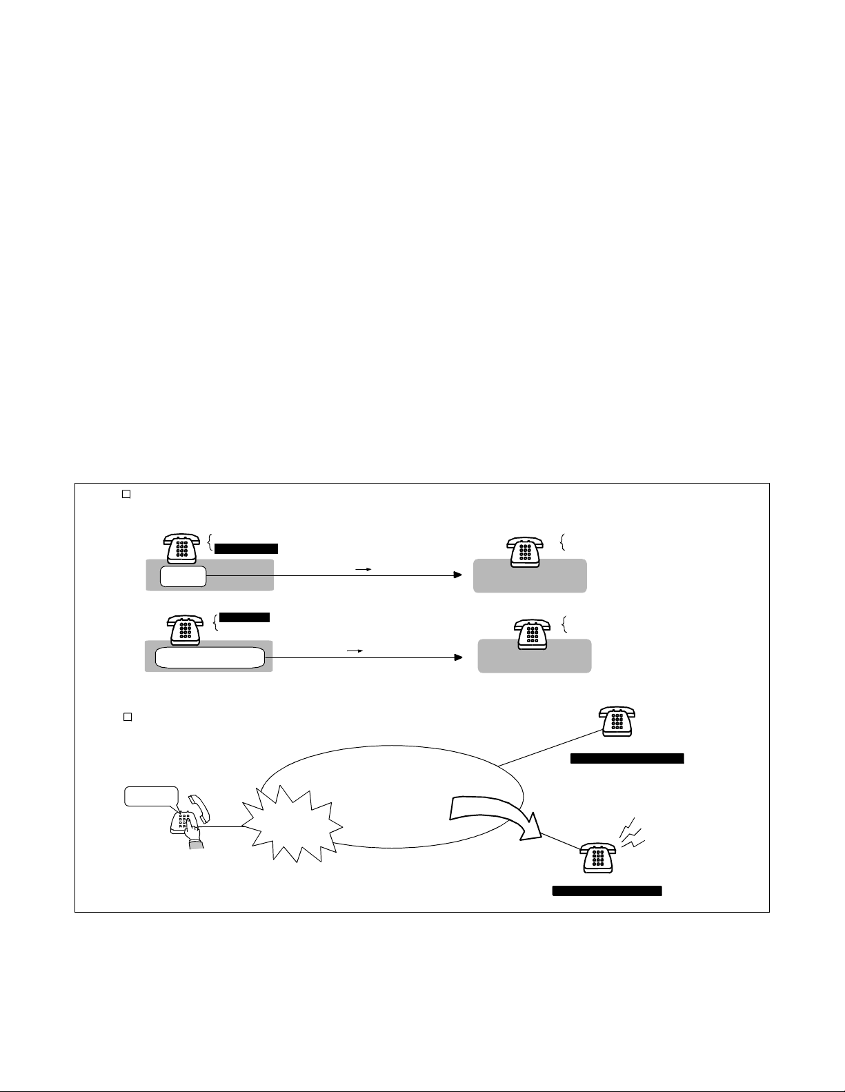
1.2 Use of Telephone Numbers
A Fusion system allows you to use telephone numbers in addition to the existing station numbers. (In the
remainder of this manual, the existing station numbers are referred to as Physical Station Numbers.) Fusion
service features are activated when a telephone number is dialed. The telephone number, which can be
assigned on a station basis, is a unique number on a Fusion network. If required, numbering plan data,
which is identical to that of an existing station number, can be used to maintain consistency of the
numbering plan. When this plan is adopted, you can use the same numbering plan data after introducing
the Fusion system. Figure 2-1 illustrate s the use of teleph one number s in the Fusion netw ork.
Note:
A maximum of 16 digits can be used as a telephone number.
Telephone Number can be assigned to a station by using the LENs or by the Physical Station Number depending on the program ming
as shown below.
¥ When using LENs
STN: 2000
LENS: 000010
LENS
¥ When using Physical Station Number
STN: 2000
LENS: 000010
Physical Staio n N u m b er
Fusion features are activated when a Telephone Number is dialed.
Telephone Num ber
410001
dialing a Telephone Number.....
LENS: 000010 410000
S TN : 20 00 410 000
Fusion features
are activated.
Fusion Netw ork
Telephone Num ber: 410000
Telephone N um ber: 410000
STN: 2000
LENS: 000010
STN : 2000
LENS: 000010
STN a
STN : 2000
Telephone Num ber: 410000
STN b
STN : Physical Station Numb er
STN: 2500
Telephone N umber: 410001
Figure 2-1 Telephone Number
NDA-24299 CHAPTER 2
Page 3
Revision 1.0
Page 19
GENERAL
Free Numbering
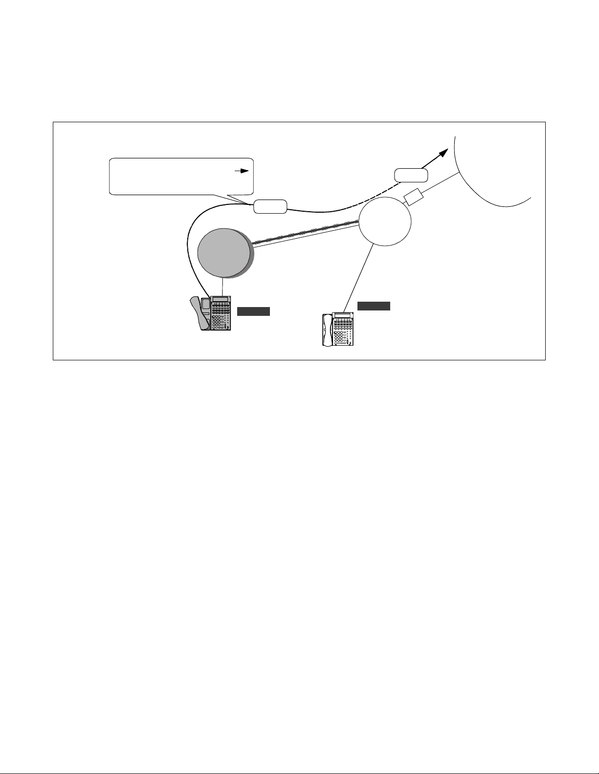
2. Free Numbering
A telephone number can be assigned to a desired station on the Fusion network with the simple command
operation shown in Figure 2-2.
In this figure, the user is changing the location of Telephone Number "411111" to N ode B.
C
h
MAT
Telephone #: 411111
STN: 2000
Node A
Logical N um ber
411111
Node A
a
n
g
e
l
o
c
a
t
i
o
n
Node C
Note:
Telephone #: 411111
STN: 2000
Node B
Note
user
The AlGSN command is used for assigning Telephone Numbers. See 5.6 “Assignment of Telephone
STN 2000
NCN
Fusion Network
NCN: Network Control Node
STN: Physical Station Number
Node B
LN
STN 2000
LN
STN 2000
LN: Local Node
Numbers” for more details.
Figure 2-2 Free Location
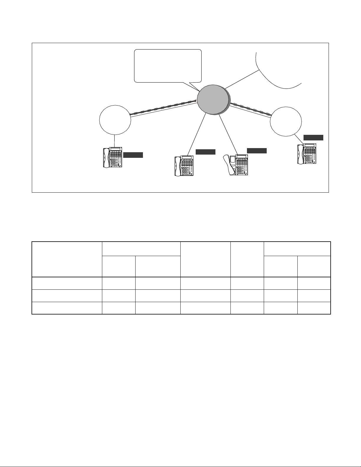
2.1 Centralized Maintenance Administration Terminal (MAT)
A Fusion network has one Network Control Node (NCN) and Local Nodes (LNs). The NCN has the
Centralized-MAT, which runs on Windows 95/NT. The MAT can collect fault information from all nodes
on the network. The NCN has Network Data Memory, which stores the data related to the network level.
The telephone numbers, for exampl e, can be change d with the Central ized-MAT at the NCN. The MAT als o
allows th e user to ma nage network-level office data. Refer to Figure 2-3
Fault inform ation can be collected at NCN via Fusion Link.
Node C
Fault Infor mation
Node A
Node B
December 12 1997
AM 3:12:13
Node B FCH Failure
M G: 00
U : 02
PRT
13-H
1. xxxx xxxx 0010 1222
4. x0010 1110 10110 1FFF
7. E23C CAAB 12 00 0 0000
NEC
MAT
13-H
1. xxxx xxxx 0010 1222
4. x0010 1110 10110 1FFF
7. E23C CAAB12 000 0000
G : 11
Note
:
:
:
Note:
Actual system message is indicated in a different format.
Figure 2-3 Centralized MAT on Fusion Network
CHAPTER 2 NDA-24299
Page 4
Revision 1.0
Fusion Network
NCN
Fa ult In for m a tio n
NCN : Network Control N ode LN: Local N ode
Fusion Link
Node B
FC H fa ult....
LN
LN
Page 20
GENERAL
Fusion System Configuration
3. Fusion System Configuration
The Fusion system can be conf igured i n the foll owing two wa ys. Figure 2-4 shows a Fusion system with Fusion
Call Control Handler (FCH) cards.
Node BNode A Node C
4.9 ft
DTI
FCH
HUB
FCH
HUB
CPU
LAN I
DTI
CPU
LANI
DTI: Digital Trunk Interface FCH: Fusion Call Control Handler LANI: LAN Interface
DTI
Fusion Link
1.5M
4.9 ft
FCH
Dch: 64K-1.5M
HUB
10BASE-T 10BASE-T 10BASE-T
Fusion Link
1.5M
4.9 ft
Dch: 64K-1.5M
DTI
FCH
4.9 ft
HUB
Figure 2-4 Fusion System Configuration (with FCH)
Figure 2-5 shows a Fusion system without Fusion Call Control Handler (FCH) cards.
his figure shows a Fusion system w ithout Fusion Call Control Handler ( FCH) cards.
DTI DTI DTI
DTI
T1 Link T1 Link
Node BNode A Node C
DTI
DTIDTI
CPU
LANI
DTI
CPU
LANI
Fusion Link Fusion Link
10BASE-T 10BASE-T
T I: D ig ita l T ru n k In te rfac e L A NI: LA N Inter fa c e
Figure 2-5 Fusion System Configuration (without FCH)
CPU
LANI
HUB
CPU
LANI
NDA-24299 CHAPTER 2
Page 5
Revision 1.0
Page 21

GENERAL
Node
4. Node
A Fusion network consists of the following types of nodes:
• Network Control Node
The Network Control Node, which must be assigned on a Fusion network, manages other nodes on the
network. This no de has the Ce ntral ized- MAT to coll ect fa ult i nformat ion f rom other nodes on the netw or k.
Multiple nodes cannot be assigned as a Network Control Node.
• Local Node
All nodes other than the Network Control Node are called Local Nodes. Fault information generated at a
Local Node is sent to the Network Control Node via a Fusion link, allowing the Network Control Node to
collect the fault information. A Fusion network can have a maximum of 16 nodes on the network.
Figure 2-6.
See
Note:
The actual number of nodes varies with system configurations.
• Center Node (for Centralized Billing - Fusion)
This node collects the billing information from other nodes as well as the self-node. For this reason, the
node is called Center Node for Cent rali zed Bil ling - Fusion. Mul tiple Cent er Nodes can be as signed on th e
network by spe cifying the poll ing dest inations , which ca n be set by the ASYDL command - S YS 1 Ind ex es
608 through 639. At the Center Node, the user can select “polling destinations” by setting 1 to the FPC of
the corresponding nodes. For more information, see the NEAX2400 IPX Office Data Specification.
A Fusion network can have a maximum of 16 nodes.
N13
N14
N12
N15
N11
N16
N10
N1
N2
N9
N3
N4
N5
N6
N7
N8
N: Node
Figure 2-6 Maximum System Configuration
CHAPTER 2 NDA-24299
Page 6
Revision 1.0
Fusion netw ork
Page 22

GENERAL
Data Memory Configuration
5. Data Memory Configuration
Each node on a Fusion network has the following three kinds of Data Memory:
• Data Memory (DM)
• Local Data Memory (LDM)
• Network Data Memory (NDM) - Programmable only by the NCN.
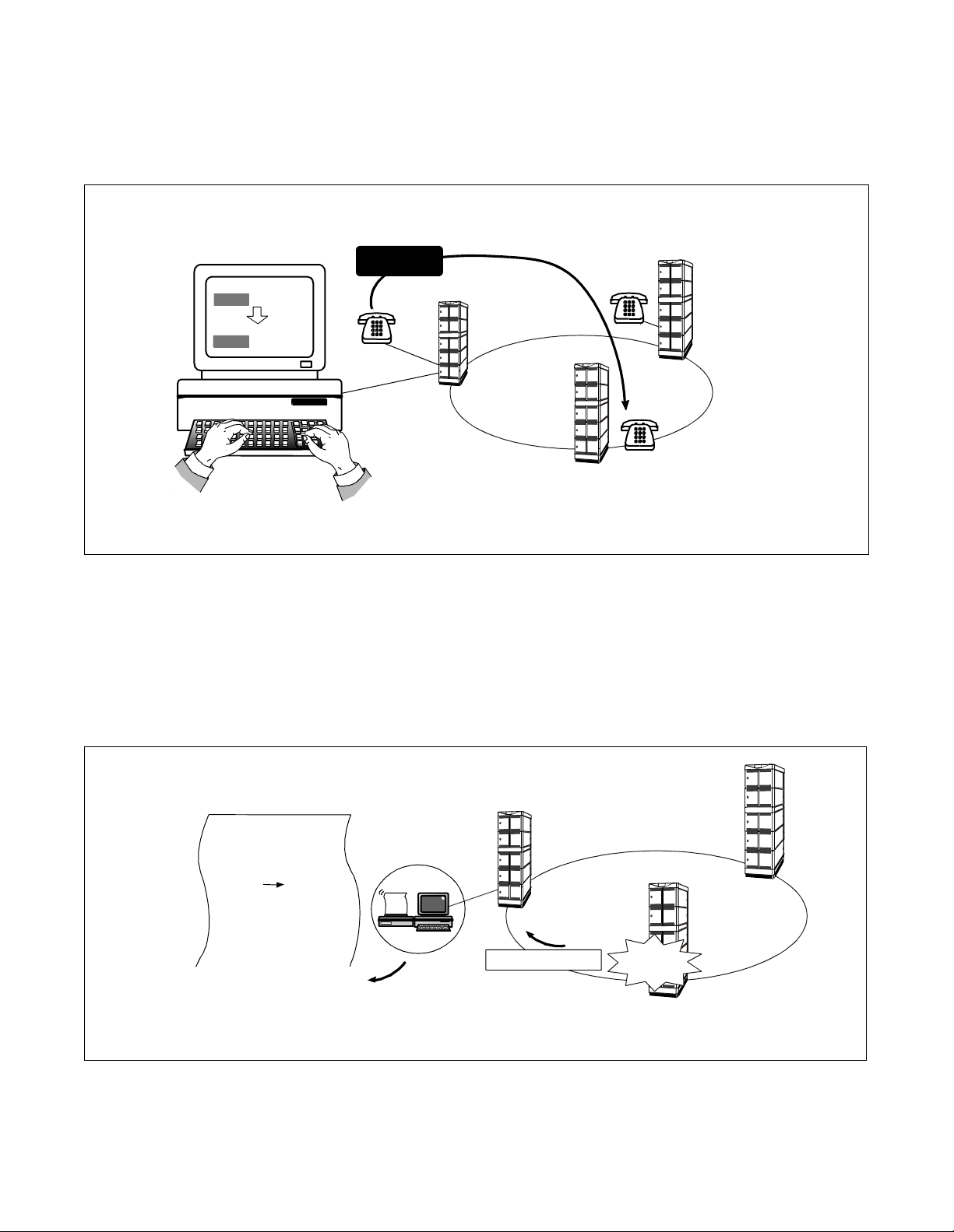
When the contents of the NDM are changed at NCN, the new data is automatically copied to the NDM of each
node. The NDM of the NCN functions as primary memory. Figure 2-7 shows how a telephone number change
is performed in a Fusion network.
When telephone numbers are changed, the change at the NCN will affect all nodes on the network. In this
figure, data change at Node A is automatically transferred to each node.
410000
Centralized
MAT
Data Change...
Telephone Number Change
410000 410001 (for self-Node)
420000 420001 (for Node B)
430000 430001 (for Node C)
440000 440001 (for Node D)
Note:
The data must be manually transferred with the CBCN command when the Fusion system is
410001
TCP/IP
configured for the first time or the system is once initialized at the NCN.
NCN
Node A
updating NDM
at each node
NDM (master)
Node B
LN
Node C
LN
Node D
LN
copy
copy
copy
420000
NDM
NDM
440000
NDM
430000
420001
430001
440001
Figure 2-7 Network Data Memory
NDA-24299 CHAPTER 2
Page 7
Revision 1.0
Page 23
GENERAL
Fusion Network Examples
When the NDM (primary) is modified, the new data is automatically copied. See Figure 2-8
Change...
Fusion Link
NCN
DM
LDM
NDM
(m a ste r)
copy
The standard size of each mem ory is as follows:
LN LN
DM DM
LDM
NDM
LDM
NDM
copy
DM (Data Memory): 4M Bytes
LDM (Local Data Memory): 2M Bytes
NDM (N e tw o rk D a ta M e mo ry) : 2M B y tes
NCN: Network Control Node LN: Local Node
Figure 2-8 Network Data Memory Copy
6. Fusion Network Examples
Figure 2-9 and Figure 2-10 show ex amples of Fusi on networks. When i ncorporating the Fusion sys tem with the
existing CCIS network, connect all nodes via CCIS links.
Note:
To co nnect a CCIS network and Fusion network, use STNs and TEL Ns re spectively.
3x x x : CCIS for Nod e C
[Closed N um bering]
2x x x : CCIS for Nod e B
1xxx: self-Node
4xxxxx: FU SIO N acc ess
5x x x : CCIS a c c e s s f o r
C C IS Ne two rk
NCN
Node A
FPC = 1
PC =10
LN
Node C
FPC= 3
FCC S
CCIS
PC = 12
... ... ... ... ...
... ... ... ... ...
... ... ... ... ...
... ... ... ... ...
TELN
410000
... ... ... ... ...
... ... ... ... ...
... ... ... ... ...
... ... ... ... ...
STN: 3000
TELN
430000
STN: 1000
STN: Physical Station Number TELN: Telephone Number FPC: FUSION Point Code PC: Po in t Code (CCIS)
Figure 2-9 Closed Numbering Fusion-CCIS Network
CHAPTER 2 NDA-24299
Page 8
Revision 1.0
S
I
C
C
... ... ... ... ...
... ... ... ... ...
... ... ... ... ...
... ... ... ... ...
STN: 1001
FCC S
CCIS
TELN
410001
C CIS
Network
"5xxx"
LN
Node B
FPC = 2
PC = 11
TELN
420000
... ... ... ... ...
... ... ... ... ...
... ... ... ... ...
... ... ... ... ...
STN: 2000
Page 24
[Open Numbering]
LN
Node C
"82"
FPC= 3
PC = 12
... ... ... ... ...
... ... ... ... ...
... ... ... ... ...
... ... ... ... ...
STN: 2000
TELN
430000
81: CCIS for Node B
82: CCIS for Node C
8x: CCIS access for
CCIS Network
4x...: Fusion access
FCCS
CCIS
... ... ... ... ...
... ... ... ... ...
... ... ... ... ...
... ... ... ... ...
STN: 2000
NCN
Node A
"80"
FPC = 1
PC =10
TELN
410000
S
I
C
C
410001
... ... ... ... ...
... ... ... ... ...
... ... ... ... ...
... ... ... ... ...
STN: 2001
GENERAL
Fusion Network Exampl es
CCIS
Network
"8x"
FCCS
LN
CCIS
TELN
Node B
"81"
FPC = 2
PC = 11
STN: 2000
TELN
420000
... ... ... ... ...
... ... ... ... ...
... ... ... ... ...
... ... ... ... ...
Figure 2-10 Open Numbering Fusion-CCIS Network
[conditions for telephone number digits]
When incorporating the Fusion system with the CCIS netwo rk, consider the conditions in Table 2-1 as to the
available telephone number digits.
Telephone Number
Composition
4 digits or less Note
4~8digits Note
9 digits or more Note
Display
D
term
ATTCON/
DESKCON
Inter-Office
Service
MCI
×× × ×××
× - × - ××
-- - --×
Table 2-1 Available Tele phone Nu mber Dig its
SMDR
CCIS Fusion
×: Availab le -: Not available
Note:
When the network is Open Numbering, the “digits” in the table abo ve must be the number of “office code
digits + telephone number digits”.
NDA-24299 CHAPTER 2
Page 9
Revision 1.0
Page 25
GENERAL
Tandem Connections via Fusion Link
7. Tandem Connections via Fusion Link
Tandem connections via FCCS-ACIS can be established. In Figure 2-11, STN (A) can place a tandem call via
FCCS-ACIS.
Tandem connection FCCS
ACIS is established.
LN
Node A
calling party
... ... ... ... ...
... ... ... ... ...
... ... ... ... ...
... ... ... ... ...
STN (A)
Figure 2-11 Tandem Connections via Fusion Link
FCCS
TELN
430000
FCCS
... ... ... ... ...
... ... ... ... ...
... ... ... ... ...
... ... ... ... ...
STN (B)
NCN
Node B
TELN
410000
ACIS
O
C
CO
T
CHAPTER 2 NDA-24299
Page 10
Revision 1.0
Page 26
CHAPTER 3 SYSTEM CONFIGURATION
Fusion systems can be divided into the following two types:
• Fusion system with FCH
• Fusion system without FCH
Note:
FCH (Fusion Call Control Handler) : PA-FCHA
This chapter explains the system configuration of each Fusion system.
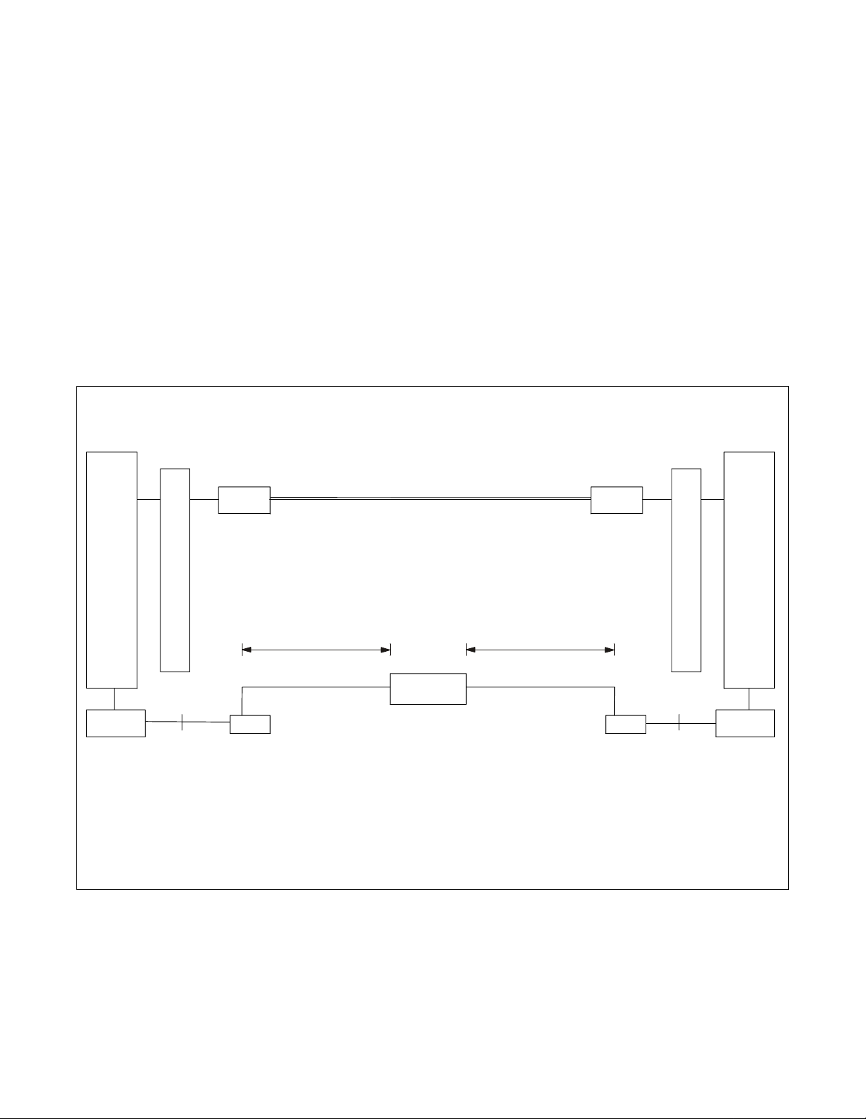
1. FUSION System without FCH
An example system configuration of Fusion system which does not use a DTI to carry D-channel is shown
below. In this configuration, Fusion link is established between nodes via Ethernet. The DTI card carries Bchannels only in this example. See Figure 3-1 below.
This figure shows a Fusion System Configura tion without FCH.
Node A
TS W/IN T TS W/IN T
MUX
DTI DTI
B-channel
Node B
MUX
10 Base T
CPU
PCI Bus
TSW (Time Division Sw itch): P H-SW 10
MUX: PH-PC36
LA NI (L AN In te rfa c e ): P Z-P C19
DTI (Digital Trunk Interface): P A-24DT R
Note:
A maximum of 4 HUBs can be cascaded between the originating node and the incoming node.
LANI
(Restriction by operating condition of Ethernet.)
Figure 3-1 FUSION System Configuration without FCH
Max. 100m
Note
Max. 100m
10 Base T
LANI
CPU
PCI Bus
D-channel
Fusion Link
HUB
NDA-24299 CHAPTER 3
Page 11
Revision 1.0
Page 27
SYSTEM CONFIGURATION
Fusion System with FCH
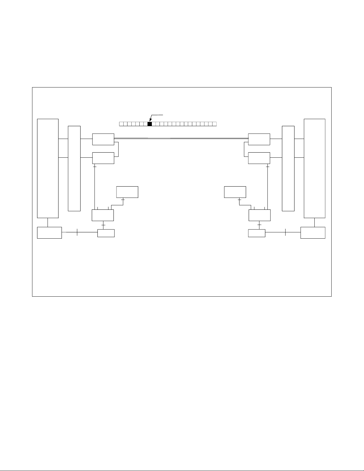
2. Fusion System with FCH
2.1 System Configuration
A sample system configuration of Fusion system which uses a DTI to carry D-channel is shown below. In
this configurat ion, Fusion link is established bet w een nodes via the T1 link. See Figure 3-2 below.
This figure shows a Fusion S ystem Configuration with FCH .
Node A
TSW /INT TSW /INT
MUX
DTI DTI
FCH
10 Base T
......
HUB
CPU
PCI Bus
TSW (Time Division Switch): PH-SW 10
HUB: PA-M96
MUX: PH-PC36
LANI (LAN Interface): PZ-PC19
FCH (Fusion Call Control Handler): PA-FCH A
DTI (Digital Trunk Interface): P A-24DTR
LANI
ch 0
D/I D/I
FCH FCH
10 Base T
D-channel (example)
Fusion Link
B-channel / D -channel
ch 23
FCH
10 Base T
......
HUB
10 Base T
LAN I
PCI Bus
Node B
MUX
CPU
Figure 3-2 Fusion System Configuration with FCH
CHAPTER 3 NDA-24299
Page 12
Revision 1.0
Page 28
SYSTEM CONFIGURATION
Fusion System with F CH
Note:
When a direct connection is added to the existing Fusion system with FCH card between the two nodes, it
is required to execute Make Busy operation (MB Key ON/OFF) on the FCH cards to prevent from packet
loop.
Node BNode A
DTI
CPU
LANI
10BASE-T
DTI DTI
FCH
Fusion Link
1.5M
MB key ON/OFF
HUB
Connect the HUBs with a cross cable
DTI
FCH
HUB
CPU
LANI
DTI : Digital Trunk Interface FCH : Fusion Call Control Handler LANI : LAN Interface
Figure 3-3 Add a Direct Connection to Fusion System with FCH
On other occasions for adding direct connection (connect cross cable between the HUBs) to the Fusion
network consists of mu ltiple n odes, also perform th e MB key ON/OFF oper ation on j ust a sin gle FCH card
to prevent from packet loop. See Figure 3-3
When the system applies dual configura tion, MB Key ON/OFF opera tion is to be exe cuted to an FCH car d
on each #A/#B side.
2.2 Redundancy of FUSION Link
FCH (PA-FCHA) card handles a Fusion link, occupying one time slot of a frame by D/I function equipped on
the DTI card. In terms of redundancy, Fusion system (with FCH) can have one of the following configuratio ns.
• Redundant Configuration (LANI, HUB, FCH, and DTI)
• Redundant Conf igu rat ion (HUB, FCH, and DTI)
• Redundant Configuration (FCH and DTI)
• Non Redundant Conf iguration
NDA-24299 CHAPTER 3
Page 13
Revision 1.0
Page 29
SYSTEM CONFIGURATION
Fusion System with FCH
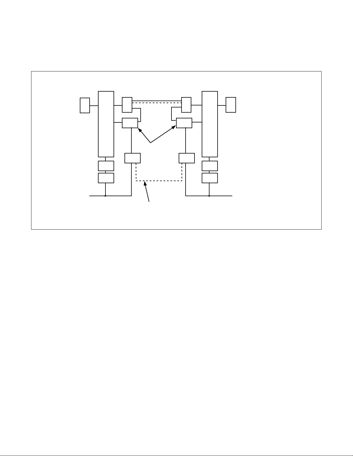
Figure 3-4 shows LANI, HUB, FCH, and DTI in a fully redundant configuration.
CPU#0
CPU#1
LANI#0-A
LANI#0-B
LANI#1-A
LANI#1-B
....
HUB0
HUB1
....
Redundancy
10 Base T
10 Base T
Figure 3-4 Redundant Configuration (LANI, HUB, FCH, and DTI)
Figure 3-5 shows HUB, FCH, and DTI in a redundant configuration.
PCI Bus
PCI Bus
LANI#0CPU#0
10 Base T
LANI#1CPU#1
10 Base T
....
HUB
HUB
....
10 Base T
10 Base T
10 Base T
FCH0
FCH1
FCH
FCH
DTI
to the same route
DTI
DTI
to the same route
DTI
Figure 3-5 Redundant Configuration (HUB, FCH, and DTI)
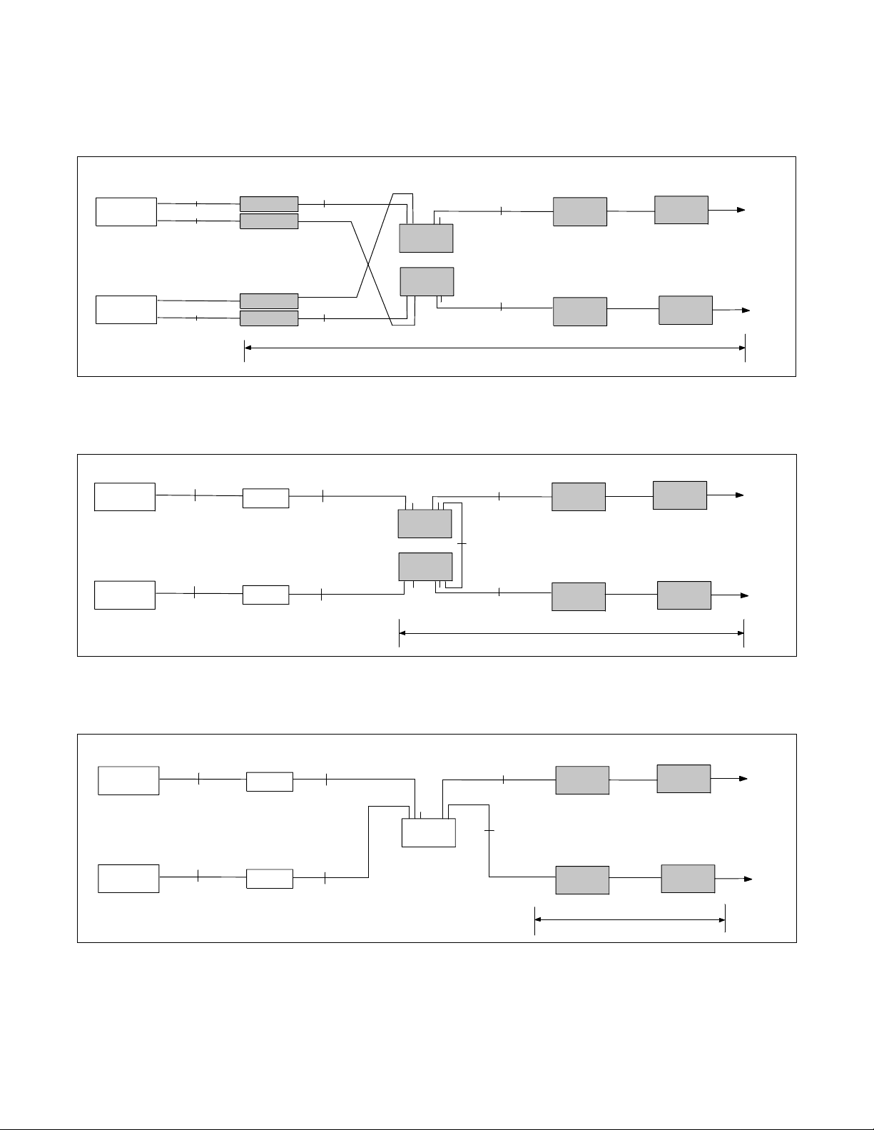
Figure 3-6 shows FCH and DTI in a redundant configura ti on.
LANI#0CPU#0
PCI Bus
LANI#1CPU#1
PCI Bus
CHAPTER 3 NDA-24299
Page 14
Revision 1.0
10 Base T
....
HUB
10 Base T
Figure 3-6 Redundant Configuration (FCH and DTI)
10 Base T
10 Base T
Redundancy
FCH
FCH
DTI
to the same route
DTI
Redundancy
Page 30
In this case, no redundancy is taken as to Fusion link.
SYSTEM CONFIGURATION
Fusion System with F CH
CPU#0
PCI Bus
PCI Bus
LANI#0
10 Base T
LANI#1CPU#1
10 Base T
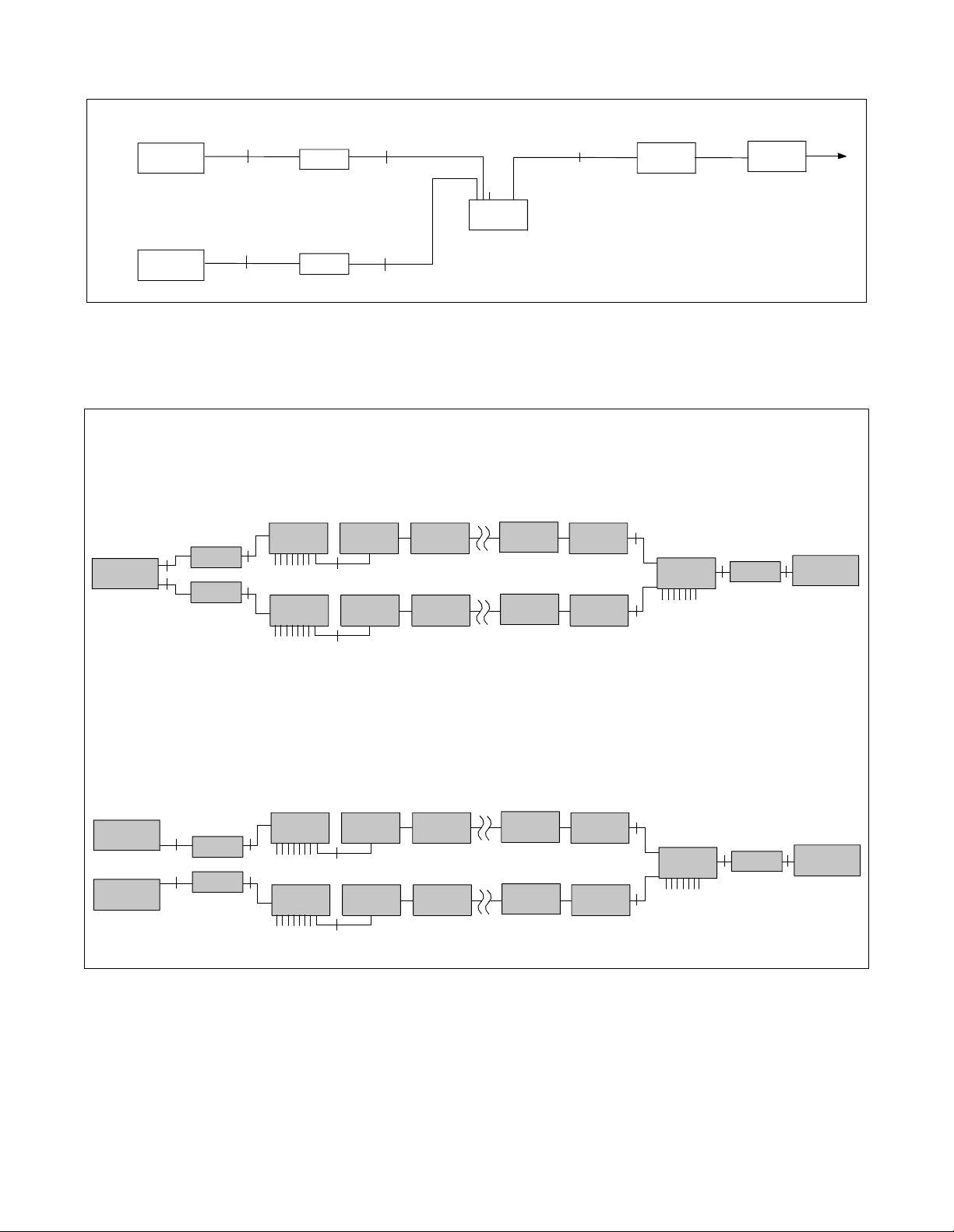
Figure 3-7 Non-Redundant Configuration
Note:
Be sure that the system configurations shown below are not available. The Node composed of dual-HUB
system cannot apply to the opposite side agai nst a Node with single-HUB configuration.
[Pattern 1]
Node A: CPU=single, HUB=dual, LANI=dual
Node B: CPU=single, HUB=single, LANI=single
CPU#0
PCI Bus
PCI Bus
10BASE-T
LANI-A
LANI-B
10BASE-T
HUB-A
HUB-B
FCH
10BASE-T
FCH
10BASE-T
DTI
DTI
HUB
....
DTI
DTI
10 Base T
FCH
FCH
FCH
10BASE-T
HUB-A
10BASE-T
LANI-A
10BASE-T
DTI
CPU#0
PCI Bus
[Pattern 2]
Node A: CPU=dual, HUB=dual, LANI=dual
Node B: CPU=single, HUB=single, LANI=single
PCI Bus
CPU#0
CPU#1
10BASE-T
LANI-A
LANI-B
10BASE-T
PCI Bus
HUB-A
HUB-B
FCH
10BASE-T
FCH
10BASE-T
Figure 3-8 Unavailable System Configurations
DTI
DTI
DTI
DTI
FCH
FCH
10BASE-T
HUB-A
10BASE-T
LANI-A
10BASE-T
CPU#0
PCI Bus
NDA-24299 CHAPTER 3
Page 15
Revision 1.0
Page 31

SYSTEM CONFIGURATION
System Considerations
3. System Considerations
3.1 Fusion Network Conditions
This section exp lains condition s when designing a Fu sion network. I n the follo wing diagram, a Fu sion Link
is printed in a thick line w h ile a CCIS link is printed in a do tted line.
Condition 1: The maximum number of nodes on a Fusion network is sixteen (16) nodes.
exam ple 1
Node A
FCCS
4
FCCS
Node B
3
F
C
C
S
S
C
C
F
1
FCCS
example 2
Node A
FCCS
FCCS
1
S
C
C
F
Node B
2
Node C
2
FCCS
Node D
Node D
R ou tin g fro m N o d e A No d e C Ro u ting fro m No de D N o d e C
Node A Node B Node D Node C
1
Node A Node D Node C
2
Node A Node B Node C
3
No d e A N o d e C
4
exam ple 3
Node A
FCCS
Node B
FCCS
Node C
FCCS
Node D
Node A
N o de D Nod e A No de B Nod e C
1
No d e D N o de B N o d e C
2
example 4
FCCS
Node B
FCCS
Node C
FCCS
Node C
Node D
FCCS
Node E
Figure 3-9 Fusion Network Topologies
CHAPTER 3 NDA-24299
Page 16
Revision 1.0
Page 32

SYSTEM CONFIGURATION
System Considerations
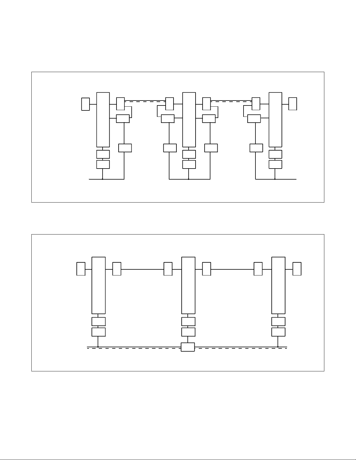
Condition 2: A maximum of four (4) Non ACD nodes can be connected as tandem nodes with 1D
channel.
• 64k (1D-channel) will support 4 nodes
• 128k (2D-channels) will support 5 n odes
• 256k (4D-channels) will support 6 n odes
See Figure 3-10.
Node A
maximum 4 Non ACD nodes
FCCS FCCS
Node B
Node C Node D
Tandem Connection over FCCS links
FCCS
Figure 3-10 Fusion Tandem Connections
Condition 3: The available connection-route number ranges from 1 to 1023.
Condition 4: The available connection-trunk number of each route ranges from 1 to 4095.
See Figure 3-11.
DTI
card
:
:
:
:
DTI
card
IPX/IMX
DTI
card
:
:
:
:
DTI
card
T1
T1
IPX/IMX
DTI
card
:
:
:
:
DTI
DTI
card
card
T1
T1
DTI
card
:
:
:
:
DTI
card
IPX/IMX
C_RT
D ch
D ch
Max 4095 trunks per connection-route
B ch
max 4095 ch
A maximum of 4095 ports can be assigned on a
connection-route basis between nodes.
D ch: Data Link
B ch: Connection Trunk
Figure 3-11 Maximum Number of Ports between Nodes
NDA-24299 CHAPTER 3
Page 17
Revision 1.0
Page 33

SYSTEM CONFIGURATION
System Considerations
Condition 5: Up to eight (8) routes can be assigned as alternate routes for a connection trunk.
See Figure 3-12.
Node
Alt-C_RT1
Alt-C_RT2
Node A
Alt-C _RT: Alternate C onnection Route
Alt-C_RT3
Alt-C_RT4
Alt-C_RT8
Node
Node
Node
:
:
:
:
Node
Figure 3-12 Connection Trunk Alternate Routing
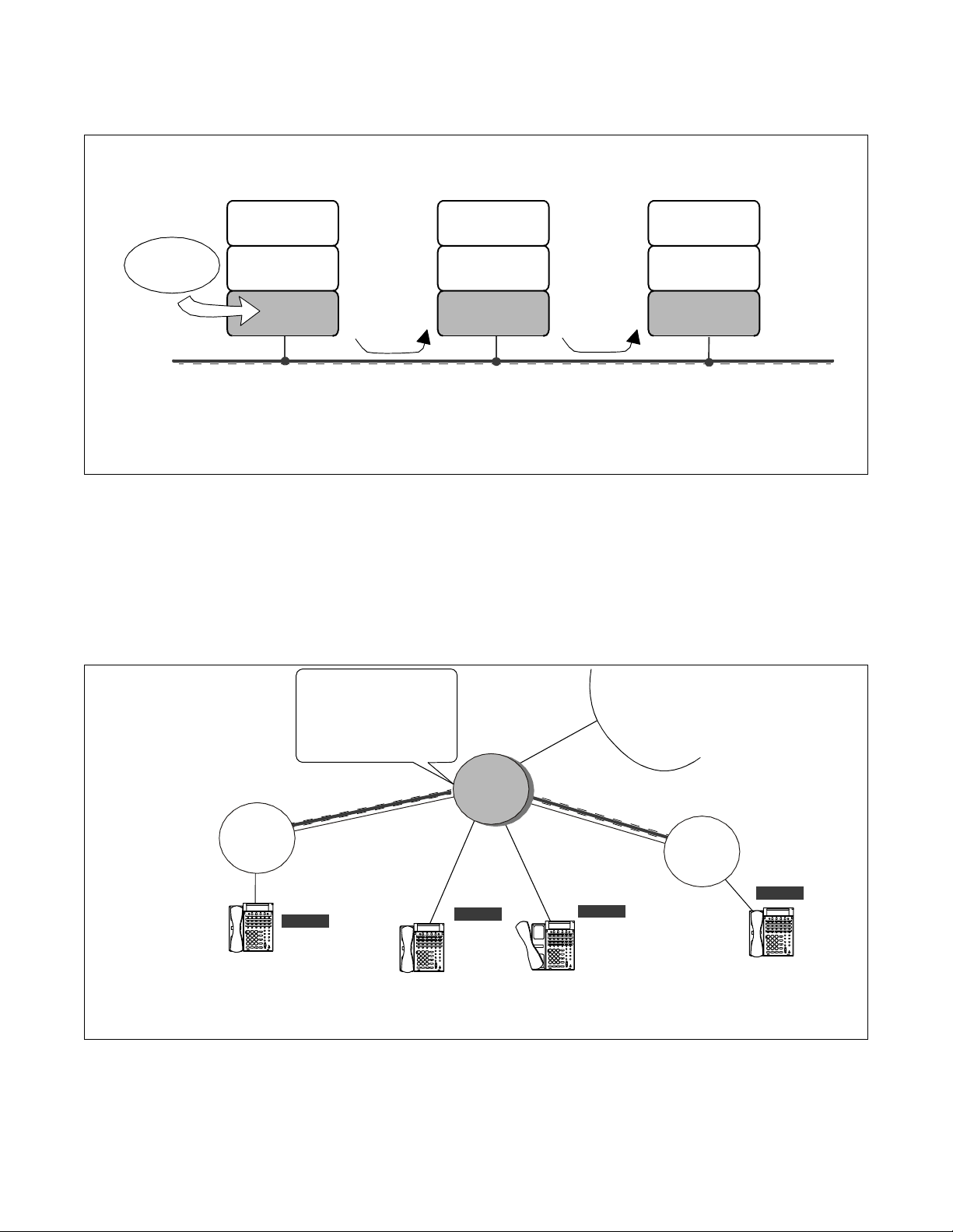
Condition 6: Connection trunks and the Fusion data link must be assigned on an “associated” basis.
See Figure 3-13.
NCN
Centralized
MAT
Node A
updating NDM
at each node
Node C
copy
430000
Node B
430001
TCP/IP
Data Change...
Figure 3-13 Fusion Network on an Associated Basis
Condition 7: One Fusion data link must be assigned on each T1 link.
Condition 8: A maximum of eight (8) data links can be used for a connection trunk for redundancy.
CHAPTER 3 NDA-24299
Page 18
Revision 1.0
LN
NDM
Page 34

SYSTEM CONFIGURATION
Condition 9: The maximum data link speed is “1.5 Mbps.”
Condition 10: Connec tion Trunks (B ch) conform to the following specifications:
• Existing external tr unk cannot be used as alternat e routes for connection tr unks.
• Billing information on connection trunks cannot be output.
• Under the following condi tions, “connection trunk seizure NG” will occur:
Data Link Failure
Connection Trunk all busy
LANI (built-in) - FCH failure
• Connection test for connection trunks is not provided.
• Nailed Down connection is not provided for connection trunks.
• PAD value for connection trunks is fixed to 0 db.
• Echo canceller (EC) / MPC control is not provided.
System Considerations
• Nailed Down connection is not provided for connection trunks.
Condition 11: If a “layer 2 failure” occu rs , the connections are released.
Condition 12: When fusion links and CCIS links coexist on a Fusion network, the following conditions
should be considered:
A Fusion link may be used as a CCIS link through data programming. In this instance, if the other node
accommodates a dedicated CCIS card, CCIS will not work even if the self-node accommodates a FusionLink-Card. Therefore, the same Fusion-Link-Card must be accommodated at both nodes. Figure 3-15
shows an example of CCIS-FUSION networks.
NDA-24299 CHAPTER 3
Page 19
Revision 1.0
Page 35

SYSTEM CONFIGURATION
System Considerations
3.2 Centralized Billing - Fusion (Polling Method)
This section explains the conditions of Centralized Billing - Fusion, focusing on when CCIS links are
involved. To use this feature, select Center Node(s) on the Fusion network. See Figure 3-14.
Example 1
- Node A (Fusion - C enter Node) collects the billing information of N odes B and C via FCCS using polling method.
Fusion - Center Node
Fusion Network
IPX
12345566
451566465
876464646
646522130
0221313131
654654654
polling
billing information
of Node B
IPX
SMDR equipment
Node A
FCCS
1
2
3
4
4
5
5
5
1
6
5
8
6
6
7
6
6
4
4
6
6
6
4
5
4
6
6
5
0
4
2
2
6
2
2
1
1
6
3
3
5
0
1
4
3
6
1
5
3
4
1
6
5
4
billin g in forma tion
of Node C
Node C
Example 2
In either case, "Centralized Billing - CCIS" is used. (The size of call base table is 144 B ytes.)
CCIS - Center Node
IPX
CCIS
Billing F o rm a t: CC IS
144 Bytes Call Base Table
0!KK01090010030020210
1001001002 0207 001 0010
0000000004 1111 063 41997
1225223209 1997 122 52314
0101123450 0000 000 0008
.................
Node A
IPX
CCIS
Node A
polling
FCCS
FCCS
IPX
Node B
non IPX
Node B
CCIS - Center Node
non IPX
Node B
Billing F o rm a t : C CIS
144 Bytes Call Base Table
0!KA0109 0010 030020 210
100100100202070010010
0000000004111106341997
1225223209199712252314
010112345000000000008
.................
Example 3
In either case, "Centralized Billing - CCIS" is used. (The size of call base table is 144 Bytes.)
CCIS - Center Node
IPX
CCIS
Billing F o rmat: C C I S
144 Bytes Call Base Table
0!KK01090010030020210
100100100202070010010
0000000004111106341997
1225223209199712252314
010112345000000000008
.................
Node A
IPX
CCIS
: Fusion Call Control
Signal (FCCS)
: Common Chanel
Inter-Office S ign a ling (C C IS )
Figure 3-14 Centralized Billing - Fusion (1/3)
CHAPTER 3 NDA-24299
Page 20
Revision 1.0
IPX
Node B
CCIS - Center Node
IPX
Billing Fo rm a t: C C IS
144 Bytes Ca ll Base Table
0!KK01090010030020210
100100100202070010010
0000000004111106341997
1225223209199712252314
010112345000000000008
.................
Page 36

SYSTEM CONFIGURATION
System Considerations
- Exam ple 4
- Example 5
¥ N o d e A tr ie s to colle c t th e b illin g in fo rmatio n o f No d e B , a n d N o d e C v ia F CCS u s in g p o llin g me th od .
(N o d e A c a n n o t co lle c t th e b illin g in fo rm atio n of N o d e C v ia F CCS.)
¥ N o d e C s e n d s th e b illin g in formation v ia C CIS, ig n o rin g p o llin g from No d e A .
¥ N o d e C d e lete s th e s e lf-Po in t Co d e (CCIS) wh en re q u ir in g to s end b illin g in fo r ma tio n fo r pollin g from No d e A .
Fusion - Center Node
CCIS - Center Node
SMDR equipment
IPX
Node A
CCIS
1
234
4
5
515
56
876
6
6
64
4
65
6
646
465
46
0
2
22
213
1
6
313
546
0
1
5465
31
4
Billin g In formation
of N ode C
Fusion Network
polling
FCCS
pol ling
IPX
igno res
DPC0:
Node A
Node C
¥ Node A tries to collect the billing i nformation of Node B via FCC S using pollin g method.
(Node A cannot collect the billin g i nformation of Node B via FCC S.)
¥ Nod e B s e n d s th e b illin g in fo r ma tio n to No de C v ia C CIS, ign o r in g p o llin g fro m No d e A .
¥ Nod e B d e le t es the s e lf-Po in t Code (CCIS) w h e n r e quiring to s e n d b illin g in fo rmation f or p o llin g fro m No de A .
SMD R e q uipment
Fusion - Center Node
IPX
Node A
Fusion Network
FCCS
CCIS - C e nter N od e
non IPX
CCIS
Node C
12345566
45156646 5
87646464 6
64652213 0
02213131 31
65465465 4
Billin g In for mati on
of Node B
FCCS
CCIS
1
IPX
Node B
IPX
DPC0:
ignore spolling
Node B
6
6
5
5
5
6
4
4
3
6
6
2
6
4
5
6
1
0
4
5
3
6
4
1
4
1
6
2
3
7
2
1
8
5
3
n
6
1
4
4
5
3
6
o
6
1
i
4
2
2
5
t
0
6
4
a
5
6
m
r
B
o
f
e
n
I
d
o
g
n
N
i
l
f
l
i
o
B
Node C
- Example 6
¥ N o d e A c o lle c ts th e b illin g in fo r m a t ion o f No de B a n d No d e C v ia F CCS u s in g p o llin g m eth o d .
¥ N o d e A s e n d s th e b illin g in fo r m a t ion o f Nod e A , N od e B , an d No d e C.
12345566
451566465
876464646
646522130
022131313 1
654654654
12345566
451566465
876464646
646522130
0221313131
654654654
Fusion - Center Nod e
IPX
Node A
SMD R equipm ent
CCIS - Center Node
non IPX
Node D
12345566
451566465
876464646
646522130
022131313 1
654654654
Billin g In formation
of Nodes A, B, C
CCIS
SMDR equipment
Figure 3-14 Centralized Billing - Fusion (2/3)
NDA-24299 CHAPTER 3
DPC0:
Node D
FCCS
B
i
l
o
SMDR equipment
p
o
l
l
i
n
g
Fusion Network
FCCS
polling
Billin g In fo rmat ion
of Nod e B
12345566
45156646 5
87646464 6
64652213 0
02213131 31
65465465 4
IPX
Node B
IPX
12345566
4
5
156
876464646
6
64
465
l
65
022131313 1
i
n
22
6
13
g
5
465
0
4
I
654
n
f
f
o
N
r
m
o
d
a
e
t
i
o
C
n
Node C
FCCS
Page 21
Revision 1.0
Page 37
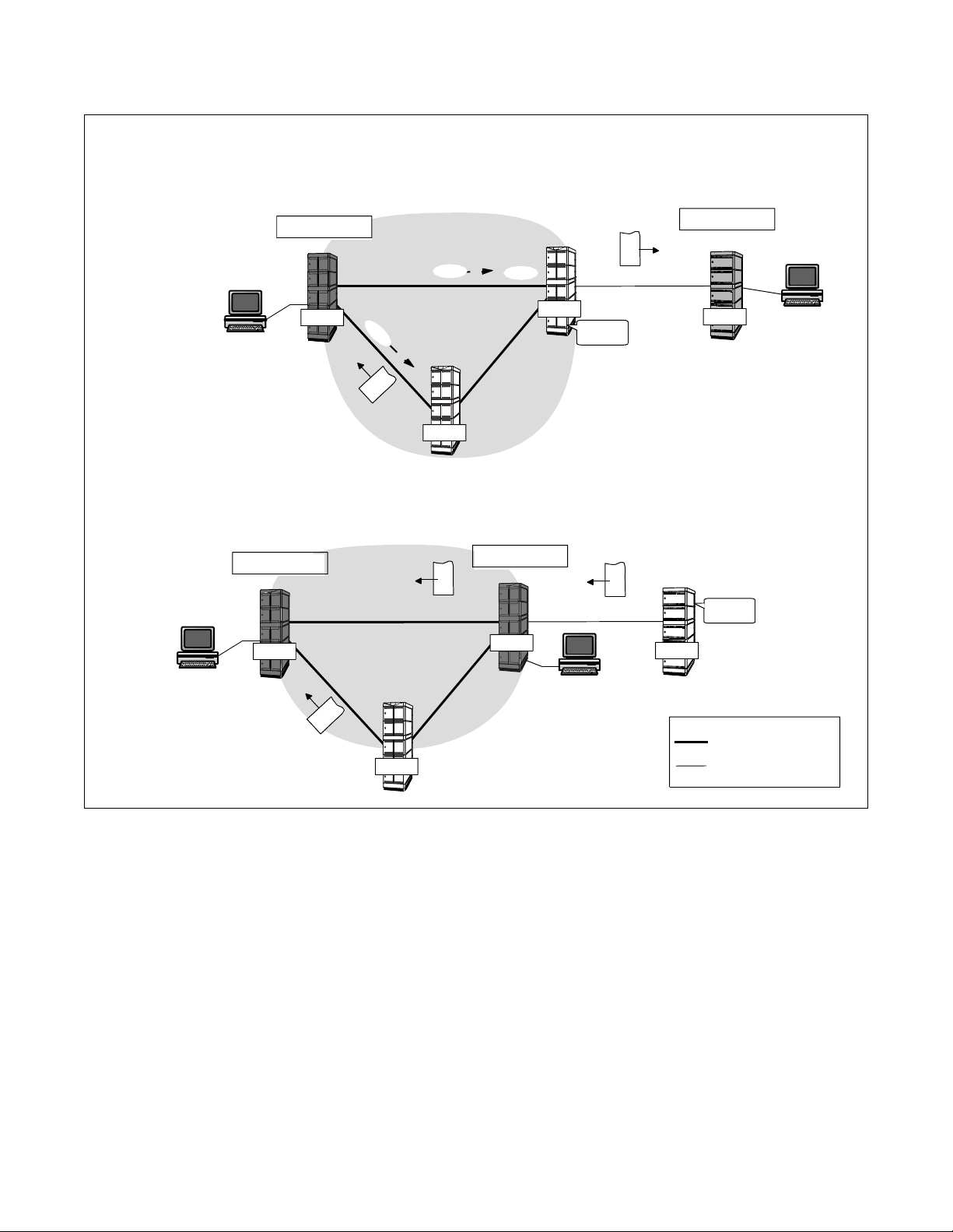
SYSTEM CONFIGURATION
System Considerations
- Example 7
¥ N o d e A c o lle c ts billin g in fo r ma t io n o f No de B a nd No d e C v ia F CCS by p ollin g metho d.
(B illin g info r matio n o f N od e B c a n n o t be c o llec te d.)
¥ N o d e B s e n d s b illin g in fo r ma t io n to No d e D v ia CCIS, ign o r in g p ollin g f ro m No d e A.
¥ N o d e B d e le t e s the s e lf -No d e P oin t Co d e (CCI S ) w he n Nod e B wa nts to s e n d b illin g info r matio n .
- Example 8
CCIS - Center Node
no n IPX
Node D
SMD R equipm ent
SM DR equipm ent
Fusion - Center Node
IPX
Node A
Fu s io n Ne twork
p
o
l
l
i
n
g
FCCS
po llin g
ign o re s
IPX
Node B
12345566
451566465
876464646
646522130
0221313131
654654654
Billing Information
of No d e B
CCIS
DPC0:
Node D
IPX
1
2
3
4
B
4
5
5
1
8
5
5
6
7
i
6
6
6
6
l
6
4
4
4
l
6
6
6
i
0
4
5
5
2
n
6
2
4
2
6
2
1
6
5
1
g
3
4
3
1
6
0
3
5
1
4
I
3
6
o
1
n
5
4
f
f
o
N
r
o
m
FCCS
d
a
e
t
i
o
C
n
FCCS
Node C
¥ N o de A c o lle c ts th e b illin g info rm ation o f No de B, No d e C, an d No d e D whic h a re s to r e d in No d e B a n d No de C b y p o llin g meth od .
¥ N o de D s e n ds b illing in f o rmation t o No de B .
12345566
451566465
876464646
646522130
0221313131
654654654
FCCS
CCIS - Center Node
IPX
Node B
Billing Information
of Node D
CCIS
SM DR equ ipment
12345566
451566465
876464646
646522130
0221313131
654654654
non IP X
DPC0:
Node B
Node D
DPC : De s tin a tio n Po in t Co d e
: Fusion C all Control
Signal (FCCS)
: Comm on C hanel
Inte r-O f fice S ig n a lin g (C C IS)
SMD R equipm ent
Fusion - Center Node
IPX
Node A
B
i
l
l
i
n
g
I
o
n
f
f
o
N
o
d
e
C
1
2
3
4
5
1
8
5
7
6
6
6
6
4
4
6
6
0
4
5
2
6
2
2
4
6
2
1
6
5
1
3
4
3
1
6
0
3
5
1
4
3
6
1
5
4
r
m
a
t
i
o
n
Fusion Network
4
5
5
6
6
4
6
5
FCCS
FCCS
IPX
Node C
Billing Information
of Node B
Figure 3-14 Centralized Billing - Fusion (3/3)
CHAPTER 3 NDA-24299
Page 22
Revision 1.0
Page 38

SYSTEM CONFIGURATION
System Considerations
3.3 Centralized Management Report-Fu sio n
For collection of fault information in a Fusion network, the Centralized Management Report-Fusion is
used. This feature provides automatic reporting of fault occurrence from Local Nodes to Center Node.
Figure 3-15 shows service conditions for this feature.
Node B
13-H
1. xx x x xxxx 0010 1222
4. x0010 1110 10110 1FF F
7. E23 C CAAB12 000 0000
NEC
Centralized MAT
Fusion
Node D
FCCS
FCCS
Node A
FCCS
Fault!
FCCS
Node C
Figure 3-15 Centralized Management Report-Fusion
• Center Node for Centralized Management Report-Fusion is specified in the following system data:
ASYDL, SYS1, Index 532 (FPC of Center Node for Centralized Management Report-Fusion).
• At Center Node, system messages received from the other nodes are stored in the buffer memory for
Centralized Management Report-Fusion.
• The MAT connected to Center Node polls only the self-node.
• Office Name (ASYD, Index 96 through 115) is used for identification of each node.
• When a system message p rint e r is conn ected to a node oth er than C e nt er Node, system messages sent
to Center Node are also output to the system message printer.
• When a system message has been sent to Center Node, the message is regarded as an old message.
• When t he s ystem fails trans mis sion of a sys tem me ssag e to Cente r Nod e, retry operation i s executed.
When the retry operation also fails, transmission is aborted, and the message is sent together with the
next system message.
NDA-24299 CHAPTER 3
Page 23
Revision 1.0
Page 39

SYSTEM CONFIGURATION
System Considerations
The following explains service conditions for the network including both FCCS and CCIS links.
Example: 1
When the network compri ses FCCS and CCIS links (See Figure 3-16.)
NEC
PRT
PC=10 FPC=4
Node A Node D
Node B Node C
PC=11
FPC=2
CCIS
FCCS
PC=12
FPC=3
FCCS
Centralized MAT
Center Node: Node C
13-H
1. x xxx x xxx 0010 1222
4. x0010 1110 10110 1FFF
7. E23C CAAB12 000 0000
NEC
Fusion
Figure 3-16 Centralized Management Report-Fusion (Example 1)
Node A: To send system messages to Node C via Office B, assign Point Code of Node C (12) to ASYD, SYS
1, Indexes 184 and 185.
Node B: To send system messages to Node C, assign Fusion Point Code of Node C (3) to ASYDL, SYS1, Index
532. When this syste m data is assig ned , system mess age s recei ved from Node A are also transf err ed
to Node C. How ever, when data is not as signed (0), system messa ges received from Node A are
ignored and not transferred to Node C.
System me ssages rec eived fro m Node A are not o utput to the syst em messag e printer connect ed to
Node B.
Node C: Received system messages are stored in the memory area for Cent ralized Manag ement Report-Fusion.
Node D: To send system messages to Node C, assign Fusion Point Code of Node C (3) to ASYDL, SYS1, Index
532.
CHAPTER 3 NDA-24299
Page 24
Revision 1.0
Page 40

SYSTEM CONFIGURATION
System Considerations
Example: 2
When both FCCS and CCIS links are established between two nodes (See Figure 3-17).
Node B Node C
13-H
1. x xxx x xxx 0010 1222
4. x0010 1110 10110 1FFF
PC=11
FCCS
FPC=2
FCCS
CCIS
PC=10 FPC=4
Node A Node D
PC=12
FPC=3
CCIS
Center Node: Node C
7. E23C CAAB12 000 0000
NEC
Centralized MAT
Fusion
Figure 3-17 Centralized Management Report-Fusion (Example 2)
Node A/B/C:Refer to
Example 1
on the previous pag e.
Node D: When Point Code of Node C (12) is assigned to ASYD, SYS 1, Indexes 184 and 185, System
messages are sent to Node C with use of CCIS. When this system data is not assigned (0), and
Fusion Point Code of Node C (3) is assigned to ASYDL, SYS 1, Index 532, system messages are
sent to Node C using FCCS.
NDA-24299 CHAPTER 3
Page 25
Revision 1.0
Page 41

SYSTEM CONFIGURATION
System Considerations
Example: 3
When a node is li nked with LAN interface (See Figure 3-18.)
NEC
PRT
PC=2 FPC=12
13-H
1. xxxx xxxx 0010 1222
4. x0010 1110 10110 1FFF
7. E2 3C CAA B12 000 0000
NEC
Centralized MAT
Fusion
CCIS
PC=1
Node E
Node A
Figure 3-18 Centralized Management Report-Fusion (Example 3)
Node B Node C
PC=3
FCCS
FPC=11
CCIS
FCCS with LAN
Node D
Center Node: Node E
FPC=10
Node A: To send system messages to Node E, assign Point Code of Node C (1) to ASYD, SYS 1, Indexes
184 and 185.
Node B: To send system messages to Node E, assign Point Code of Node C (1) to ASYD, SYS1, Indexes
184 and 185. When this system data is assigned, system messages received from Nodes C and D
are also transferred to Node E. However, when this data is not assigned (0), system messages
received from Nodes C and D are igno red and not tra nsferred to Node E.
System messages received from Nodes C and D are not output to the system message printer
connected to Node B.
Node C/D: To send system messages to Node E via Node B and Node A, assign Fusion Point Code of Node B
(11) to ASYDL, SYS 1, Index 532.
Node E: Received system messages are stored in the memory area for Centralized Management Report-
Fusion.
CHAPTER 3 NDA-24299
Page 26
Revision 1.0
Page 42

3.4 Fusion Attendant/Desk Console
3.4.1 Operator Call
The user can place an operator call from each node by assigning the access code using the ASPAL/
ASPAN command, which allows the user to specify an appropriate node on the Fusion network by
entering th e FPC. In this example, a station user at N ode B can ca l l up an operat or at Node C or Node
E by dialing “90” or “91.” See Figure 3-19.
SYSTEM CONFIGURATION
System Considerations
Note 1:
Regar di ng the followi ng data (Waiting Call Display data), be sure to develop the unif ied data at eac h node:
ASYD, SYS2, INDEX 8
ASYD, SYS2, INDEX 9
Note 2:
When the connection routes (C_RT) are all busy, the operator call becomes in Night ATT mode.
ASPAL - Node A
ACC: 90 SRV: SSC
SID: 2 (operator call)
FPC = 3 (Node C)
Data Programming (Node A )
Operator Call
"90"
Node A
"90"
Operator Call
Node C
"90"
Fusion Network
Node B
ASPAL - Node B
ACC: 90 SRV: SSC
SID: 2 (operator call)
FPC = 3 (Node C)
ACC: 91 SRV: SSC
SID: 2 (operator call)
FPC = 5 (Node E)
Node D
"91"
Operator Call
"91"
Operator Call
Node E
ASPAL - Node D
ACC: 91 SRV: SSC
SID: 2 (operator call)
FPC = 5 (Node E)
Data Programming (Node D)
"91"
: Node having ATTCON/DESKCON
: Node w/o ATTCON/DESKCON
Data Programming (N o de B)
Figure 3-19 Operator Calls on a Fusion Network
NDA-24299 CHAPTER 3
Page 27
Revision 1.0
Page 43

3.4.2 Central Office Incoming Call (Ring Down)
Each node can specify a terminating node for Ring Down calls using the system data. In this example,
Node A and Node D specify Node C and Node E as the terminating node respectively. The t er mina ti ng
node is assigned with us e of the ASYDL c ommand ( SYS 1, Index 640). Note that self-FPC is assigned
at the termi n ating node. Se e Figure 3-20.
Note 1:
When assigning the da ta regar ding the call termination to ATT, be sure to develop the unified data at each
node.
Note 2:
Note 3:
Terminating node cannot be assigned differently at each tenant (TN).
When the connection routes (C_RT) are all busy, any attempted call via C.O. Line is not connected to the
ATT. As a res ult, the c alling pa rty is provided with the ringbac k tone , and e ven when a C_RT later b ecomes
idle, the ringback tone connection is still maintained, and the C.O. call does not terminate to the ATT.
ASYDL - Node A
Index 640
FPC = 3 (Node C)
Node providing ATTCON/DESKCON
Data Programming (Node A )
PSTN
Node A
FPC = 1
Ring Down Call
Node C
FPC = 3
Fusion Network
Node B
PSTN
Node D
FPC = 4
Ring Down Call
Node E
FPC = 5
ASYDL - Node D
Index 640
FPC = 5 (Node E)
Node providing
ATTCON/DESKCON
Data Programming (Node D)
ASYDL - Node C
Index 640
FPC = 3 (Node C)
self-node FPC
Data Programming (Node C)
Ring Down Call
PSTN
Figure 3-20 Ring Down Calls on a Fusion Network
CHAPTER 3 NDA-24299
Page 28
Revision 1.0
: Node having ATTCON
: Node w/o ATTCON
Page 44

SYSTEM CONFIGURATION
System Considerations
3.4.3 Day/Night Change
Day/Night information is transferred from an ATTCON/DESKCON to predetermined nodes. In this example,
Node C specifies Node A and Node B a s destination nod es by assignin g FPCs 1 and 2 in Inde xes 704-735. Node
A and Node B specify Node C as a terminating node for Ring Down calls from PSTN by assigning FPC 3 in
Index 640. Node E specifies Node D as a destination. See Figure 3-21.
Note 1:
When assigning ATTCON/DESKCON on the Fusion network, be sure to develop the unified System Data
at each node.
Note 2:
Terminating node cannot be assigned differently at each tenant (TN).
by ATTCON/DESKCON
Data Programming (Node C)
ASYDL - Node C
Index 704 - 735
D/N information are
transferred: FPC: 1, 2
: Day mode
: Night mode
Day
Fusion System with ATTCON/DESKCON
Node A
FPC = 1
D/N information
Node C
FPC = 3
Node B
FPC = 2
Node D
FPC = 4
D/N information
Node E
FPC = 5
ASYDL - Node E
Index 704 - 735
D/N information are
transferred: FPC: 4
Data Programming (Node E)
Night
Figure 3-21 Day/Night Information Transfer by ATTCON/DESKCON
When an ATTCON/DESKCON is not provided on the Fusion network, Day/Night information is effective for
a node accommodating an exter nal key box. See Figure 3-22.
by External Key Box
ATTCON
: Day mo de
: Night mode
Key Box
Day
Node A
Node B
Node C
Fusion System without
ATTCON/DESKCON
Figure 3-22 Day/Night Information Transfer
NDA-24299 CHAPTER 3
Node D
Node E
Key Box
Night
External Key Box
ATTCON
Page 29
Revision 1.0
Page 45

SYSTEM CONFIGURATION
System Considerations
This page is for your notes.
CHAPTER 3 NDA-24299
Page 30
Revision 1.0
Page 46
CHAPTER 4 INSTALLATION
This chapter covers the installation of the Fusion system. The following topi cs are covered:
• How to set switches on the following circuit cards:
PA-M96 (HUB)
PA-FCHA (FCH)
PA-24DTR (DTI)
• How to mount the circuit cards
• How to run the 10 BASE-T cables
1. Anti-Static Caution
This manual provides Static Caution indicators when describing work involving static-sensitive components.
When performing work a ccompani ed b y this mark, b e sure t o use t he anti -s tati c kit. Figure 4-1 shows the Static
Caution indicator.
ATTENTION
Contents
Static Sensitive
Handling
Precautions Requir ed
Figure 4-1 Static Caution Indicator
NDA-24299 CHAPTER 4
Page 31
Revision 1.0
Page 47

INSTALLATION
Anti-Static Caution
Figure 4-2 shows the an ti-s tat ic kit tha t is provide d and ho w to use it . Use th e kit when hand ling s tati c-sens itiv e
components such as circuit cards and cables.
Connect the ground wire to the earth terminal of the frame.
PBX
Earth Terminal
Ground Wire
Conductive Sheet
Wrist Strap
Ground Cable
Figure 4-2 How to Use the Anti-static Kit
CHAPTER 4 NDA-24299
Page 32
Revision 1.0
Page 48

INSTALLATION
Anti-Static Caution
1.1 Circuit Cards Required
Depending on the system typ e, the follo wing circuit car ds are required for in stallation of t he Fusion system.
See Figure 4-3.
• Fusion with FCH
HUB (PA-M96)
FCH (PA-FCHA)
DTI (PA-24DTR)
• Fusion without FCH
DTI (PA-24DTR)
HUB (PA-M96)
Before starting installation, make sure th at all necessary cards are at yo ur site.
DTI (PA-24DTR)
HUB (PA-M96)
FCH (PA-FCHA)
1234
12345678
OFF
1234
1234
OFF
OFF
12345678
OFF
2345678
1
OFF
12345 8
12345678
12345678
OFF
OFF
1
OFF
OFF
12345678
12345
OFF
DTI: Digital Trunk Interface
FCH: Fusion Call Control Handler
4
6
2
0
A
E
C
Figure 4-3 Circuit Cards for Fusion
1234
1234
OFF
OFF
78
123456
123456
OFF
OFF
1234567 8
12345678
OFF
OFF
234567
1
8
234567
1
OFF
OFF
12345678
12345678
OFF
OFF
78
4
6
2
0
A
E
C
C
A
0
2
6
4
8
NDA-24299 CHAPTER 4
Page 33
Revision 1.0
Page 49

INSTALLATION
Key Setting on Circuit Car ds
2. Key Setting on Circuit Cards
2.1 PA-M96 (HUB)
After referring to Figure 4-4 and Table 4-1, set the SEL switch on the H UB (PA-M9 6) card(s).
Note:
OPE
ST7
ST0
SENSE
TP7-X
TP6-X
TP5-X
TP4-X
TP3-X
TP2-X
TP1-X
TP0-X
MB
~
CR7
CR0
4
6
2
0
A
E
C
C
E
A
0
2
6
4
HUB (PA-M96) Card
~
4
2
6
0
E
C
A
.
Set the SENSE Switch arrow to the proper direction,
referring to Table 4-1.
1 and 4 to F of the SENSE Switch are not available in this version.
Figure 4-4 Switch Setting on HUB (PA-M96) Card
ATTENTION
Contents
Static Sensitive
Handling
Precautions Required
.
SENSE Switch
Table 4-1 SENSE Switch Setting
SWITCH NAME SETTING
SENSE
0 Polarity indication on the STn lamps for TPn-Xports.
STANDARD
SETTING
1 Not used.
4
2
6
0
E
C
A
2 × TPn-X ports operate as a repeater HUB. (Standard setting)
3
Data-Packet-Collision indication on the STn lamps for TPn-X
ports.
4-F Not used.
CHAPTER 4 NDA-24299
Page 34
Revision 1.0
DESCRIPTION
Page 50

INSTALLATION
Key Setting on Circuit Cards
2.2 PA-FCH A (FCH)
Set the switches on t he FCH (PA-FCHA) card( s) by refer ring to Fig ure 4- 5, Table 4-2, and Table 4-3 . This
card has DIP switches, whose key settings determine the ti m e slots of th e Fusion link. In Figure 4-5, CH3
is designated as the D/I channel in an example.
D / I channel = CH3 (example)
12345678
OFF
CH:
17 18 19 202122 2 3
16
12345
OFF
CH:
89101112 13 14 15
234
1
OFF
CH:
01234567
67
5678
SW13
8
SW12
SW11
Note: Multiple choices are
available.
FCH (PA-FCHA) Card
1234
OFF
Refer to Table 4-3.
1234
OFF
12345678
OFF
12345678
OFF
12345678
OFF
12345 678
OFF
SW14
SW13
SW12
SW11
SW10
SW14
10-BASE-T
1234
OFF
78
123456
OFF
12345678
OFF
12345678
OFF
12345678
OFF
LYR
LB
LOAD
MNT
MODE
FCH
MB
DTI
OPE
ATTENTION
Contents
Static Sensitive
Handling
Precautions Required
Make-busy-request
3
2
EST3
EST2
EST1
EST0
PWALM
4
6
2
0
A
E
C
C
E
A
0
2
6
4
1
Not Used
0
MNT
4
2
6
0
.
E
C
A
.
MODE
Refer to Table 4-2.
ON: T203 Timer = Variable
OFF: T203 Timer = 10 secs. (Standard Setting)
12345678
OFF
SW10
Not Used
Figure 4-5 Switch Setting on FCH (PA-FCHA) Card
NDA-24299 CHAPTER 4
Page 35
Revision 1.0
Page 51

INSTALLATION
Key Setting on Circuit Car ds
Table 4-2 MODE Switch Setting
SWITCH NAME SETTING
STANDARD
SETTING
MODE 0-7 Not used
4
2
6
0
E
C
A
8 ×
9
A-F Not used
Table 4-3 DI P Switch (SW14) Set tin g
SWITCH NAME
SW14
SWITCH
NUMBER
SETTING
ON × Positive logic for the D/I CONT
1
1234
OFF
OFF Negative logic for the D/I CONT
ON ×
2
Note 1
OFF
ON ×
3
Note 1
OFF
DESCRIPTION
Standard setting
(When the DTI is connected with the card’s front cable)
Fusion link test mode
(When the DTI is connected with the card’s front cable)
STANDARD
SETTING
DESCRIPTION
The fusion data link speed inserted onto the T1
interface Note 3
SW14-2 SW14-3 SPEED (Note 2)
ON ON 64Kbps × n (1~24)
ON OFF 48Kbps × n (1~24)
OFF ON 56Kbps × n (1~24)
OFF OFF Not used
4
ON LAPD signal link performs as “network.”
OFF LAPD signal link performs as “user.”
Note 1:
64Kbps is used for T1 or E1 interface.
56Kbps is used for T1 interface with bit steali n g.
48Kbps is used for T1 interface with both bit stealing and Zero Code Suppression (or Bit 7 Stuffing) .
Note 2:
Note 3:
When n is bigger than 1, Time Slot Sequence Integrity (TSSI) must be guaranteed at the network side.
The following is an example key setting when n = 2.
SW11-1 = ON
SW11-2 = ON
ON
1
OFF
CH
021324354657687
SW11
CHAPTER 4 NDA-24299
Page 36
Revision 1.0
ON
1
OFF
CH
829310411512613714815
SW12
ON
1
OFF
CH
16217318419520621722823
SW13
Page 52

INSTALLATION
Key Setting on Circuit Cards
2.3 PA-24DTR (DTI)
There are two types of the PA-24DTR (DTI) card as shown below. Refer to Figure 4-6 and Table 4-4 to set
each switch to the proper positions.
DTI (PA-24DTR) Card
Note:
Dots printed in DIP switches represe n t the standard settings.
SWITCH NAME
ATTENTION
Contents
Static Sensitive
Handling
Precautions Required
12345678
OFF
SW25
1234
1
OFF
OFF
SW4D SW5D
12345678
12345678
OFF
OFF
SW39
12345678
OFF
SW58
12345678
OFF
234
1234
OFF
12345678
OFF
2345678
1
OFF
1234
OFF
234567
1
OFF
SW6C
N-OPE
PCM
FRM
BER
RMT
AIS
SW13B
BL23
BL00
MB
CN2
OPE
Figure 4-6 Switch Locations on DTI (PA-24DTR) Card
Table 4-4 S witch Setting Patterns for the DTI Card
SWITCH
NUMBER
SETTING
STANDARD
SETTING
MEANING
MB
SW13B
0
UP Circuit card make busy
DOWN × Circuit card make busy cancel
0
ON Internal Loopback: Set
OFF × Internal Loopback: Cancel
1
3
2
1
2
ON External Loopback: Set
OFF × External Loopback: Cancel
ON Payload Loopback: Set
OFF × Payload Loopback: Cancel
3
ON All Channel Make Busy: Set Note
OFF × All Channel Make Busy: Cancel
NDA-24299 CHAPTER 4
Page 37
Revision 1.0
Page 53

INSTALLATION
Key Setting on Circuit Car ds
Table 4-4 Switch Setting Patterns for the DTI Card (Continued)
SWITCH NAME
SW4D
12345678
OFF
SWITCH
NUMBER
1
2
3
4
5
6
7
SETTING
STANDARD
SETTING
MEANING
ON Transmission Signal A Logic: Negative
OFF × Transmission Signal A Logic: Positive
ON Receiving Signal A Logic: Negative
OFF × Receiving Signal A Logic: Positive
ON RMT Alarm Sending: Not to be sent out
OFF × RMT Alarm Sending: To be sent out
ON ×
OFF
Simultaneous Seizure Supervision: Not to be
controlled
Simultaneous Seizure Supervision: To be
controlled
ON Data Link Control: MOS
OFF × Data Link Control: BOS
ON Multiframe Selection: 12-Multiframe
OFF Multiframe Selection: 24-Multiframe
ON
OFF
Signal Selection: AMI (Alternate Mark
Inversion)
Signal Selection: B8ZS (Bipolar with 8 Zeros
Substitution)
SW25
OFF
1234
8ON × Fixed
ON × Impedance setting: 100 Ω
1
OFF Impedance setting: 110 Ω
ON
Transformer at Middle Point – Transmission:
Ground
2
OFF ×
Transformer at Middle Point – Transmission:
Open
ON Transformer at Middle Point Receive: Ground
3
OFF × Transformer at Middle Point Receive: Open
ON Idle Code: To be sent out
4
OFF × Idle Code: Not to be sent out
CHAPTER 4 NDA-24299
Page 38
Revision 1.0
Page 54

Key Setting on Circuit Cards
Table 4-4 Switch Setting Patterns for the DTI Card (Continued)
INSTALLATION
SWITCH NAME
SW39
4
3
1
2
OFF
SWITCH
NUMBER
1
2
3
4
5
SETTING
ON
OFF ×
ON ×
OFF
ON ×
OFF
ON ×
OFF
ON ×
OFF
STANDARD
SETTING
MEANING
SW39-1 SW39-2 PAD CONTROL
ON ON Both directions
OFF ON Receiving only
ON OFF Sending on ly
OFF OFF ARTD is fixed
SW39-3 SW39-4 DA TA PAD
ON ON 64K
OFF ON 56K
ON OFF 48K
OFF OFF 64K INV.
ON
6
OFF ×
SW39-5 S W 39-6 T SIG CONTROL
ON ON ABCD
OFF ON ABAB
ON OFF
OFF OFF AAAA
Bit steal is in-
hibited
ON ×
7
OFF
ON
8
OFF ×
SW39-7 S W 39-8 R SIG CONTROL
ON ON ABCD
OFF ON ABAB
ON OFF
OFF OFF AAAA
Bit steal is in-
hibited
NDA-24299 CHAPTER 4
Page 39
Revision 1.0
Page 55

INSTALLATION
Key Setting on Circuit Car ds
Table 4-4 Switch Setting Patterns for the DTI Card (Continued)
SWITCH NAME
SW6C
1234
OFF
SW58
1234
OFF
SWITCH
NUMBER
SETTING
STANDARD
SETTING
1ON × Fixed
2ON × Fixed
3ON × Fixed
4ON × Fixed
5ON × Fixed
6ON × Fixed
7ON × Fixed
8ON × Fixed
ON Equalizer Setting
1
OFF
ON
2
OFF
ON
3
OFF
MEANING
SW
58-1
ON ON ON
ON ON OFF
ON OFF ON
ON OFF OFF
OFF ON ON
SW
58-2
Other Combinations Not Allowed
SW
58-3
DISTANCE
0 - 131 ft.
(0 - 040 m)
131 - 262 ft.
(40 - 080 m)
262 - 393 ft.
(80 - 120 m)
393 - 524 ft.
(120 - 160 m)
524 - 656 ft.
(160 - 200 m)
ON
4
OFF ×
ON ×
5
OFF
ON ×
6
OFF
ON
7
OFF ×
ON ×
8
OFF
CHAPTER 4 NDA-24299
Page 40
Revision 1.0
PAD Pattern Selection
SW
58-4
OFF ON ON PAD Pattern 1
OFF ON OFF PAD Pattern 2
ON OFF ON
ON OFF OFF A→ µ Loss (Receive)
OFF OFF ON
OFF OFF OFF µ→A Loss (Receive)
SW
58-5
Other Combinations Not Allowed
SW
58-6
PAD PATTERN
A→ µ Loss
(Bothway)
µ→A Loss
(Bothway)
Note: When setting this key, refer to Digital
PAD Setting Table (Table 4-5).
Alarm Sending when this circuit card is in NOPE state.
Page 56

Key Setting on Circuit Cards
Table 4-4 Switch Setting Patterns for the DTI Card (Continued)
INSTALLATION
SWITCH NAME
SW5D
1234
OFF
Note:
This switch sett ing is applicable for a sys tem that adopts Associated Channel In ter of fice Signalling (A CIS) .
2.4 Digital PAD Setting
The PA-24DTR card is equipped with a mask R OM in which th e follo wing t ypical PAD patterns ha ve bee n
already written. PAD value is determined with the selection of a desired PAD pattern, which can be done
by key sett ing of the SW 58 (ele ments 4, 5, 6) on t he card, and pr ogramming of t he PAD data by the ARTD
command - CDN = 30 (PAD). Refer to Table 4-5 for the PAD patterns and ARTD data.
SWITCH
NUMBER
SETTING
ON
STANDARD
SETTING
MEANING
Digital PAD ROM selection: Special
specification
1
OFF ×
Digital PAD ROM selection: Standard
specification
ON × LAYER2 signal lo gic: Positive
2
OFF LAYER2 si gnal logic: Negative
ON Line fault is not notified to the upper CPU
3
OFF × Line fault is notified to the upper CPU
4 ON Zero Code Suppression is not provided
PAD
DAT A
ARTD
CDN=
30
1
2
3
4
5
7
Note:
Table 4-5 Digital Pad Setting
PAD Pattern [dB] (Selected by key setting)
PAD Pa ttern 1 PAD Pattern 2
SEND RECEIVE SEND RECEIVE SEND RECEIVE SEND RECEIVE SEND RECEIVE SEND RECEIVE
22
-3
Note
300000000
A→µ Loss
(Bothway)
A→µ Loss
(Receive)
µ→A Loss
(Bothway)
µ→A Loss
(Receive)
44334 4044404
6606 6 6 0 12 6 6 0 12
88398 8088808
Key setting of SW 39-3,4 correspond to PAD values. (Regardless of PAD patterns)
0 0 0 0 Through Through Through Through Through Through Through Through
Stands for 3[dB] GAIN.
NDA-24299 CHAPTER 4
Page 41
Revision 1.0
Page 57

INSTALLATION
Mounting Circuit Cards in PIM
3. Mounting Circuit Cards in PIM
3.1 Mounting HUB (PA-M96) in a PIM
Mount the HUB (PA-M96) card in an appropriate slot of a PI M as shown in Figure 4-7. When the MAT is
connected via a HUB card, be sure to use a dedicated HUB for the Fusion link.
Note:
HUB (PA-M96) can be mounted anywhere in a PIM of any IMG stack. However, if your system is 1-IMG
type, mount the HUB in PIM0.
Mount a HUB card in an appropriate slot providing the anti-static kit.
P
I
M
1
P
I
M
0
HUB
HUB
PA-M96
ATTENTION
Contents
Static Sensitive
Handling
Precautions Required
Anti-static Kit
Figure 4-7 Mounting HUB Card in PIM 0
CHAPTER 4 NDA-24299
Page 42
Revision 1.0
Page 58

INSTALLATION
Mounting Circuit Cards in PIM
3.2 Mounting FCH (PA-FCHA) and DTI (PA-24DTR) Cards
Mount the FCH (PA-FCHA) and the DTI (PA-24DTR) card in appropriate slots in a PIM. Mount the two
cards in adjacent slots since these cards must be connected on the front connectors. Figure 4-8 shows an
example with the FCH and DTI cards mounted in PIM 1.
PIM 1
PIM 0
DTI (PA-24DTR)
DTI (PA-24DTR)
FCH(PA-FCHA)
FCCH(PA-FCCHA)
HUB
HUB
HUB
HUB
ATTENTION
Contents
Static Sensitive
Handling
Precautions R equired
Anti-static Kit
Figure 4-8 Mounting FCH and DTI Cards
NDA-24299 CHAPTER 4
Page 43
Revision 1.0
Page 59

INSTALLATION
Connecting Cables
4. Connecting Cables
4.1 Connecting DTI-FCH Front Cables
Connect the furnished front cable to the connectors on the DTI and FCH cards. Use DTI and CN2
connectors on the FCH and DTI cards respectively. Since an FCH card is equipped with one Handler
circuit, a maximum of f i ve FCH cards can be connected to a DTI card. (Se e Figure 4-9.) Ho wev er, if a DCH
card is also cascad ed, a maximum of thr ee FCH cards ca n be added to the DTI card. (DCH is e quipped with
two Handler circuits per card.)
FCH(PA-FCHA)
OPE
MB
10AL(10)FLT CA
2
10AL(10)FLT CA
DTI (PA-24DTR)
OPE
MB
ATTENTION
Contents
Static Sensitive
Handling
Precautions Required
2
DTI
FCH
FRONT V IEW
CN2
10AL(10)FLT CA
Figure 4-9 Connecting Front Cables
Anti-statik K it
FRON T VIEW
CHAPTER 4 NDA-24299
Page 44
Revision 1.0
Page 60

INSTALLATION
Connecting Cables
Since a maximum of five Handler circuits can be used, five FCH cards can be cascaded. Figure 4-10 shows an
example where three FCH cards are cascaded.
FCH x 3
10AL(10)FLT CA
DTI
OVERVIEW
FCH(PA-FCHA)
2
2
2
DTI
FCH
FRONT VIEW
Figure 4-10 FCH Cascade Connections
DTI
(PA-24DTR)
10AL(10)FLT CA
CN2
ATTENTION
Contents
Static Sensitive
Handling
Precautions Required
NDA-24299 CHAPTER 4
Page 45
Revision 1.0
Page 61

INSTALLATION
Connecting Cables
4.2 Connecting 10 BASE-T Cables
Figure 4-11 shows sample cable connections, where HUB (PA-M96) cards are provided in a dual
configuratio n and the FCH (PA-FCHA) card is loca ted in PIM 1 (1-I MG system/IMG0) . When HUB cards
are provided in a dual configuration, the two HUB cards must be connected on each front edge connector
with a 10 B ASE-T cross cable. Ho we v er , when dual LANIs (LANI-A and LANI-B) are us ed for each CPU,
the cross cable connection bet w een HUBs for FCH#0 and #1 is not necessary.
Note:
The Ethernet cables shown in the e xamples in this secti on are NO T availab le fr om NEC. The customer must
provide these cables, depending on the system configuration. See “Chapter 6 Connecting 10 BASE-T
Cables.”
DTI (PA-24DTR)
ATTENTION
FCH (PA-FCHA)
DTI
P
I
M
1
(
H
P
U
A
B
-
M
9
10 BASE T cable
(cross)
(
H
P
I
M
0
P
U
A
B
-
M
9
6
)
(
H
P
U
A
B
-
M
9
6
)
6
)
GT
LANI (PZ-PC19)
Contents
Static Se n sitive
Handling
Precautions Required
10 BASE T cable
(straight)
MAT
REAR VIEW
to MAT
Note
: 10 BASE-T cable (for Fusion Link)
Note:
When connecting the MA T us ing a HUB card, be sure to use a dedicated HUB for the M AT.
Figure 4-11 Overall 10 BASE-T Connections
CHAPTER 4 NDA-24299
Page 46
Revision 1.0
GT
LANI (PZ-PC19)
10 BASE T cable
(straight)
: 10 BASE-T cable (for MAT)
Page 62

INSTALLATION
Connecting Cables
4.3 10 BASE-T Connection Procedure
The pattern for 10 BASE-T cable connections may vary, depending on the system configuration (such as
the number of IMG stacks or the mounting location/number of the FCH/HUB cards, etc.). According to
your system configu rat ion, connect necessary Ethernet cables:
4.3.1 Procedure for 1-IMG System
If your system is 1-IMG type, the 10 BASE-T connection should use either of the following cables:
1. Cable unit specified as SR1201 ETIF CAU-n
2. Cables, other than those of SR1201 ETIF CAU-n, that are provided by the user
Based on the cable type, perform the following:
4.3.2 When using cable unit SR1201 ETIF CAU-n
1. Referring to Figure 4-13 through Figur e 4- 15, connect the 10 BASE-T straight cables, between the
LANI (PZ-PC19) and HUB (PA-M96) cards, and between the HUB and FCH (PA-FCHA) cards. If
the HUB is in a dual configuration, also connect the 10 BASE-T cross cable between HUB#0 and
HUB#1.
Note:
When dual LANIs are used in both Slot 00 and 03 of CPR#0/CPR#1, be sure to use at least two
HUB cards. Use one HUB for the internal LANI (in Slot 00), and use the other HUB for external
LANI (in Slot 03). If FCH is al so in a dual conf igurati on, the 10 BASE-T cross connection between
the two HUBs is not required.
2. If your system needs more FCH (PA-FCHA) and/or HUB (PA-M96) cards, provide the required
Ethernet connection(s) for the added card(s) using the following cables:
• When adding FCH card in PIM0: UTP CTG5 ST CA-D
• When adding HUB card in PIM0: UTP CTG5 CRS CA-D
• When adding FCH card in PIM1: UTP CTG5 ST CA-K
• When adding HUB card in PIM1: UTP CTG5 CRS CA-K
• When adding FCH card in PIM2: UTP CTG5 ST CA-M
• When adding HUB card in PIM2: UTP CTG5 CRS CA-M
• When adding FCH card in PIM3: UTP CTG5 ST CA-N
• When adding HUB card in PIM3: UTP CTG5 CRS CA-N
The cables cited abo ve and use d in F i gure 4-13 through F igure 4-15 are for the 1-IMG sys tem only and a r e
not available in the 4-IM G/I MX- U syst em.
NDA-24299 CHAPTER 4
Page 47
Revision 1.0
Page 63

INSTALLATION
Connecting Cables
4.3.3 When not using the cable unit SR1201 ETIF CAU-n
When your system doesn’ t use t he cable unit cla ssif ied as SR1201 ETIF CAU-n, perform the 10 B ASET connections as instructed below:
1. Depending on your system configuration, connect the 10 BASE-T straight cable(s) between the
HUB (PA-M96) and LANI (PZ-PC19) cards. Use the cable UTP CTG5 ST CA-O, which must be
provided by the user.
When a single LANI is used for each CPR (Slot 00 only), and the HUB is in a dual configuration,
connect HUB#0 to LANI#0 and HUB#1 to LANI#1, using two 10 BASE-T cables.
When dual LANIs are used in both Slot 00 and 03 of CPR#0/CPR#1, use at least two HUB cards
as separate 10 BASE-T connection terminals: One HUB for the internal LANI (LANI-A in Slot 00
of each CPR) and the other for the external LANI (LANI-B: in Slot 03 of each CPR).
2. When HUB is in a dual conf i gurati on, con nect t he 10 BASE-T cross cable between the HUB cards.
Use the cable UTP CTG5 CRS CA-F, which must be provided by the user.
When using more than two HUB cards, connect the cross cable(s) for the remaining HUB cards,
except the HUB card used for the MAT connection.
3. Connect the 10 BASE-T straight cable(s) between the HUB and FCH (PA-FCHA) cards. Use the
following cables, which must be provided by the user.
UTP CTG5 ST CA-F:When the HUB and FCH are in the same PIM (PIM0)
UTP CTG5 ST CA-O:When the HUB and FCH are in different PIMs
When FCH is in a dual configura tion, connect FCH#0 to the HUB#0 side, and FCH#1 to the HUB#1
side.
4.3.4 Procedure for 4-IMG System
When your system is 4-IMG type, the procedure for 10 BASE-T connection is as follows. Because the
HUB (PA-M96) can be mounted anywhere i n a PIM of any IMG, the Ethernet cables mus t be arranged
by the user, depending on the system configuration.
1. Depending on your system configuration, connect the 10 BASE-T straight cable(s) between the
HUB (PA-M96) and LANI (PZ-PC19) cards. Use the following cables, prepared by the user:
UTP CTG5 ST CA-O:When the HUB and LANI are in the same IMG (IMG0)
UTP CTG5 ST CA-X:When the HUB and LANI are in different IMGs
When a single LANI is used for each CPR (Slot 00 only), and the HUB is in a dual configuration,
connect HUB#0 and HUB#1 to LANI#1 using two 10 BASE-T cables.
CHAPTER 4 NDA-24299
Page 48
Revision 1.0
Page 64

INSTALLATION
Connecting Cables
When dual LANIs are used in both Slot 00 and 03 of CPR#0/CPR#1, be sure to use at least two
HUB cards as separate 10 BASE-T connection terminals. Use one HUB for the internal LANI
(LANI-A: in Sl ot 00 of each CPR), and use the other for the externa l LANI (LANI -B in Slot 03 of
each CPR).
2. When the HUB is in a dual configuration, connect the 10 BASE-T cross cable between the HUB
cards. Use the following cables, which are provided by the user.
UTP CTG5 CRS CA-F:When the HUB and HUB are in the same PIM
UTP CTG5 CRS CA-O:When the HUB and HUB are in different PIMs but in the same IMG
UTP CTG5 CRS CA-X:When the HUB and HUB are in different IMG stacks
When using more than two HUB cards, also connect the cross cable(s) for the remaining HUB
card(s), except the HUB for the MAT connection.
This step is not necessary when your system uses dual LANIs for CPU#0/CPU#1 and FCH is also
in a dual configuration.
3. Connect the 10 BASE-T straight cable(s) between the HUB and FCH (PA-FCHA) cards. Use the
following cable, which must be provided by the user.
UTP CTG5 ST CA-F:When the HUB and FCH are in the same PIM
UTP CTG5 ST CA-O:When the HUB and FCH are in different PIMs but in the same IMG
UTP CTG5 ST CA-X:When the HUB and FCH are in different IMG stacks
When FCH is in a dual conf igurat ion, connect FCH#0 t o the HUB#0 side and FCH#1 to the HUB#1
side.
4.3.5 Procedure for IPX-U and IMX-U Systems
When your system is the IPX-U or IMX-U type (configured to a maximum of 4 L ocal Nodes + 1ISW),
the procedure for the 10 BASE-T connection is as follows. Because this system already has a Fusion
link via the HUB (PA-M96) cards, this section gives details related only to the connection between the
HUB and FCH (PA-FCHA) cards.
1. Refer to the NEAX2400 IPX Installation Manual (IMX-U Type) or the NEAX2400 IMX
Installation Manual (IMX-U Type) to make sure that the necessary 10 BASE-T (both straight and
cross) connections between the ISW and each LN (Local Node) are all securely provided.
2. Connect the 10 B ASE -T straight cable(s) be tween the HUB ( PA-M96) and FCH (PA-FCHA) cards.
Use the following cable, which must be provided by the user.
UTP CTG5 ST CA-F:When the HUB and FCH are in the same PIM
UTP CTG5 ST CA-O:When the HUB and FCH are in different PIMs but in the same IMG
UTP CTG5 ST CA-X:When the HUB and FCH are in different IMG stacks but in the same LN
UTP CTG5 ST CA-A0:When the HUB and FCH are in different LNs
NDA-24299 CHAPTER 4
Page 49
Revision 1.0
Page 65

INSTALLATION
Connecting Cables
When dual FCH is provided for the HUB dedicated to each internal LANI card (LANI-A: in Slot
00 of each CPR), connect FCH#0 to HUB#0 and FCH#1 to HUB#1.
When your system also uses the external LANI cards (LANI-B in Slot 03 of each CPR), prepare
another set of FCH cards for the HUB dedicated to the external LANI cards. Then, if the FCH is in
dual configuration, connect one FCH to the HUB for No. 0 system of the external LANI, and the
other to the HUB for the No. 1 system of the external LANI.
Figure 4-12 sho ws an e xa mple of a HUB in a du al co nf igur atio n a nd th e FCH c ard moun ted i n PIM
1 of the 1 IMG system.
DTI
P
I
M
1
3
Connect HUB and FCH using a
10 BASE-T straight cable.
R e fe r to fig u res lis te d o n th e
following pages.
2
Connect two HU B cards using
a 10 B A S E -T cro ss ca ble.
(When H U B is in dual
config uration.) Note
P
I
M
0
1
Connect the LANI and the
HUB card using a 10 BASE-T
straight cable. Eight
10 BASE-T connectors
(TP 0-X - T P7 -X ) are
furnishe d on the fro nt edge
-
of the HU B card. Use one of
the connectors.
FCH
DTI
ATTENTION
Contents
Static Sensitive
Handling
Precautions Required
3
(
H
P
U
A
B
-
(
P
H
A
U
-
B
M
9
6
)
M
9
6
)
2
1
Note
GT
LANI
GT
LANI
1
Note
Note:
This step can be skipped when dual LANIs (LANI-A and LANI-B) are used for each CPU and FCH is
pr ovided in a dual configuration.
Figure 4-12 Connecting 10 BASE-T Cables (example)
CHAPTER 4 NDA-24299
Page 50
Revision 1.0
Page 66

INSTALLATION
Connecting Cables
Figure 4-13 shows some typical examples where 10 BASE-T cables are conne cted to the FCH ca rd(s) mounte d
in PIM0 of 1-IMG system, under the conditions in Table 4-6:
Table 4-6 Connection of 10 BASE-T Cables to FCH Card(s) in PIM0 of 1-IMG
Configuration
of CPU
Pattern 1 Single Single SR1201 ETIF CAU-A × 1 HUB× 1, FCH× 1
Pattern 2 Dual Single
Pattern 3 Single Dual SR1201 ETIF CAU-A × 2 HUB × 2, FCH× 2
Pattern 4 Dual Dual
Configuration
of LAN
Used Cable Unit
(Note 1, Note 2)
SR1201 ETIF CAU-A × 1
SR1201 ETIF CAU-DA × 1
SR1201 ETIF CAU-A × 2
SR1201 ETIF CAU-DA × 2
Number of HUB/
FCH
HUB× 2, FCH× 2
HUB× 2, FCH× 2
Note 1:
Note 2:
Cables Contained in each cable unit are as follows:
SR1201 ETIF CAU-A: UTP CTG5 ST CA-D, UTP CTG5 ST CA-J
SR1201 ETIF CAU-DA: UTP CTG5 ST CA-D, UTP CTG5 ST CA-J, UTP CTG5 CRS CA-F
The cables cited in Figure 4-13 can be used in the 1-IMG system only.
HUB
Connectors for 10 BASE-T
FCH
(PA-FCHA)
(PA-M96)
CN
= 10 BASE-T Connector
Use 10 B A SE-T connectors.
TP7-X
TP6-X
TP5-X
TP4-X
TP3-X
TP2-X
TP1-X
TP0-X
FRONT VIEW
FRONT VIEW
10 BASE-T
<F C H in P IM 0 (P a ttern 1)> <FCH in P IM0 (Pa tte rn 2 )>
TOPU
PIM 3
PIM 2
FANU
PIM 1
UTP CTG5 CRS CA-F
FANU
TOPU
PIM 3
PIM 2
PIM 1
ATTENTION
Contents
Static Sensitive
Handling
Precautions Required
CN
CN
CN
UTP CTG5 ST CA-D
HUB
FCH
UTP CTG5 ST CA-J
BASEU
CN
CN
PIM 0
0604 0503020100
BSCM
LPM
0604 0503020100
CN
CN
CN
UTP CTG5 ST CA-D
FCH
HUB
UTP CTG5 ST CA-J
BASEU
CN CN
CN
CN
PIM 0
FCH
HUB
0604 0503020100
BSCM
0604 0503020100
LPM
CNCN
Figure 4-13 Examples of Ethernet Cable Connection-FCH in PIM0 (1-IMG System) (1/2)
NDA-24299 CHAPTER 4
Revision 1.0
Page 51
Page 67

INSTALLATION
Connecting Cables
<F CH in PIM0 (P a tte r n 3 ) > <F CH in PIM0 (P a tte r n 4 ) >
ATTENTION
Contents
Static Sensitive
Handling
Precautions Required
PIM 3
PIM 2
PIM 1
PIM 0
UTP CTG5 ST CA-J
LPM
CN
CN
CN
HUB
CN
FCH
TOPU
FANU
UTP CTG5 ST CA-D
UTP CTG5 ST CA-J
CN
CN
CN
HUB
FCHCN
0604 0503020100
0604 0503020100
CN
CN
BSCM
BSCM
TOPU
FANU
UTP CTG5 ST CA-D
CN
CN
CN FCH
C
N
CN
HUB
UTP CTG5 ST CA-J
CN
FCH
CN CN
CN
CN
PIM 3
PIM 2
PIM 1
CN CN
CN CN
PIM 0
HUB
0604 0503020100
UTP CTG5 ST CA-J
0604 0503020100
LPM
BASEU
Note:
When dual LANIs are used in both slot 00 and 03 of OPR (Pattern 3 or 4), be sure to use at least two
HUB cards: One HUB for internal LANI (in slot 00) and the other for external LANI (in slot 03).
However, if this is the cas e, and FCH is also in a dual conf igurat ion, the 10 BASE- T “cross” connection
between the HUBs is not required.
Figure 4-13 Examples of Ethernet Cable Connection-FCH in PIM0 (1-IMG System) (2/2)
CHAPTER 4 NDA-24299
Page 52
Revision 1.0
BASEU
Page 68

INSTALLATION
Connecting Cables
Figure 4-14 shows some typical examples where 10 BASE-T cables are conne cted to the FCH ca rd(s) mounte d
in PIM1 of 1-IMG system, under the conditions in Table 4-7:
Table 4-7 Connection of 10 BASE-T Cables to FCH Card(s) in PIM1 of 1-IMG
Configuration
of CPU
Pattern 1 Single Single SR1201 ETIF CAU-B × 1 HUB× 1, FCH× 1
Pattern 2 Dual Single
Pattern 3 Single Dual SR1201 ETIF CAU-B × 2 HUB× 2, FCH× 2
Pattern 4 Dual Dual
Configuration
of LAN
Used Cable Unit
(Note 1, Note 2)
SR1201 ETIF CAU-B × 1
SR1201 ETIF CAU-DB × 1
SR1201 ETIF CAU-B × 2
SR1201 ETIF CAU-DB × 2
Number of HUB/
FCH
HUB× 2, FCH× 2
HUB× 2, FCH× 2
Note 1:
Note 2:
Cables contained in eac h cable unit are as follows:
SR1201 ETIF CAU-B: UTP CTG5 ST CA-K, UTP CTG5 ST CA-J
SR1201 ETIF CAU-DB: UTP CTG5 ST CA-I, UTP CTG5 ST CA-J, UTP CTG5 CRS CA-F
The cables cited in Figure 4-14 can be used in the 1-IMG system only.
FCH
HUB
CN
Use 10 BASE-T connectors.
Con n e cto r s fo r 1 0 B A S E - T
(PA-FCHA)
(PA-M96)
= 10 BASE-T Connector
TP7-X
TP6-X
TP5-X
TP4-X
TP3-X
TP2-X
TP1-X
TP0-X
FRONT VIEW
FRONT VIEW
10 BASE-T
<F C H in P IM1 ( P a tte rn 1)> <F CH in P IM1 (Patte r n 2 )>
TOPU
PIM 3
PIM 2
FANU
CN
PIM 1
FCH
TOPU
FANU
CN
FCH
CN
FCH
ATTENTION
Contents
Static Sensitive
Handlin g
Precautions Required
PIM 3
PIM 2
UTP CTG5 ST CA-I
PIM 1
CN
UTP CTG5 ST CA-K
CN
HUB
UTP CTG5 ST CA-J
BASEU
CN CN
UTP CTG5 ST CA-K
PIM 0
06040503020100
BSCM
LPM
06040503020100
CN
CN
HUB
UTP CTG5 CRS CA-F
UTP CTG5 ST CA-J
BASEU
CN CN HUB
PIM 0
CN
06040503020100
CN
CN
BSCM
LPM
06040503020100
Figure 4-14 Examples of Ethernet Cable Connection-FCH in PIM1 (1-IMG System)
NDA-24299 CHAPTER 4
Page 53
Revision 1.0
Page 69

INSTALLATION
Connecting Cables
Figure 4-15 shows some typical examples where 10 BASE-T cables are conne cted to the FCH ca rd(s) mounte d
in PIM2 of 1-IMG system, under the conditions in Table 4-8:
Table 4-8 Connection of 10 BASE-T Cables to FCH Card(s) in PIM2 of 1-IMG
Configuration
of CPU
Pattern 1 Single Single SR1201 ETIF CAU-C × 1 HUB× 1, FCH× 1
Pattern 2 Dual Single
Pattern 3 Single Dual SR1201 ETIF CAU-C × 2 HUB× 2, FCH× 2
Pattern 4 Dual Dual
Configuration
of LAN
Used Cable Unit
(Note 1, Note 2)
SR1201 ETIF CAU-C × 1
SR1201 ETIF CAU-DC × 1
SR1201 ETIF CAU-C × 2
SR1201 ETIF CAU-DC × 2
Number of HUB/
FCH
HUB× 2, FCH× 2
HUB× 2, FCH× 2
Note 1:
Note 2:
Cables contained in eac h cable unit are as follows:
SR1201 ETIF CAU-C: UTP CTG5 ST CA-M, UTP CTG5 ST CA-J
SR1201 ETIF CAU-DC: UTP CTG5 ST CA-K, UTP CTG5 ST CA-J, UTP CTG5 CRS CA-F
The cables cited in Figure 4-15 can be used in the 1-IMG system only.
HUB
Connectors for 10 BASE-T
FCH
(PA-FCHA)
(PA-M96)
CN
= 10 BASE-T Connector
Use 10 BASE-T connectors.
TP7-X
TP6-X
TP5-X
TP4-X
TP3-X
TP2-X
TP1-X
TP0-X
FRONT VIEW
FRONT VIEW
10 BASE-T
<FC H in P IM 2 (P atte rn 1 )> <FC H in P IM 2 (Pa ttern 2 )>
TOPU
PIM 3
CN
FCH
FANU
PIM 2
PIM 1
CN
FCH
FANU
UTP CTG5 ST CA-M
CN
FCH
TOPU
PIM 3
UTP CTG5 ST CA-K
PIM 2
PIM 1
ATTENTION
Contents
Static Sensitive
Handling
Precautions Required
CN
UTP CTG5 ST CA-M
CN
HUB
UTP CTG5 ST CA-J
CN
BASEU
PIM 0
06040503020100
LPM
06040503020100
BSCM
Figure 4-15 Examples of Ethernet Cable Connection-FCH in PIM2 (1-IMG System) (1/2)
CHAPTER 4 NDA-24299
Page 54
Revision 1.0
CN
CN
CN
UTP CTG5 CRS CA-F
HUB
UTP CTG5 ST CA-J
BASEU
CN CN
CN
PIM 0
HUB
0604 0503020100
CN
CN
BSCM
LPM
0604 0503020100
Page 70

<F C H in P IM2 (P a tte rn 3 )> <FCH in P IM2 (P a tte rn 4 )>
INSTALLATION
Connecting Cables
ATTENTION
Contents
Static S ens itiv e
Handling
Precautions Required
TOPU
PIM 3
PIM 2
PIM 1
PIM 0
LPM
CN
FCH
UTP CTG5 ST CA-M
CN
CN
CN
HUB
UTP CTG5 ST CA-J
FANU
CN
FCH
UTP CTG5 ST CA-J
CN CN
CN
HUB
CN
CN
0604 0503020100
BSCM BSCM
0604 0503020100
CN
FCH
FANU
UTP CTG5 ST CA-M
CN
CN
CN
HUB
UTP CTG5 ST CA-J
CN
FCH
CN CN
CN
CN
TOPU
PIM 3
UTP CTG5 ST CA-K
PIM 2
PIM 1
CN
PIM 0
CN
CN
HUB
0604 0503020100
UTP CTG5 ST CA-J
0604 0503020100
LPM
BASEU
Note:
BASEU
When dual LANIs are used in both Slot 00 and 03 of CPR (Pattern 3 or 4), be sure to use at least
two HUB cards : One HUB for internal LANI (in Sl ot 0 0) and the other for external LANI (in Slot
03). However, if this is the case, and FCH is also in a dua l configuration, the 10 BASE-T “cross”
connection between the HUBs is not required.
Figure 4-15 Examples of Ethernet Cable Connection-FCH in PIM2 (1-IMG System) (2/2)
NDA-24299 CHAPTER 4
Page 55
Revision 1.0
Page 71

INSTALLATION
Connecting Cables
Figure 4-16 shows some typical examples where 10 BASE-T cables are conne cted to the FCH ca rd(s) mounte d
in PIM3 of 1-IMG system, under the following conditions:
Table 4-9 Connection of 10 BASE-T Cables to FCH Card(s) in PIM3 of 1-IMG
Configuration
of CPU
Pattern 1 Single Single SR1201 ETIF CAU-D × 1 HUB× 1, FCH× 1
Pattern 2 Dual Single
Pattern 3 Single Dual SR1201 ETIF CAU-D × 2 HUB × 2, FCH× 2
Pattern 4 Dual Dual
Configuration
of LAN
Used Cable Unit
(Note 1, Note 2)
SR1201 ETIF CAU-D × 1
SR1201 ETIF CAU-DD × 1
SR1201 ETIF CAU-D × 2
SR1201 ETIF CAU-DD × 2
Number of HUB/
FCH
HUB× 2, FCH× 2
HUB× 2, FCH× 2
Note 1:
Note 2:
Cables contained in eac h cable unit are as follows:
SR1201 ETIF CAU-D: UTP CTG5 ST CA-N, UTP CTG5 ST CA-J
SR1201 ETIF CAU-DD: UTP CTG5 ST CA-L, UTP CTG5 ST CA-J, UTP CTG5 CRS CA-F
The cables cited in Figure 4-16 can be used in the 1-IMG system only.
FCH
HUB
CN
Use 10 BASE- T connectors.
Connectors for 10 BASE-T
(PA-M96)
= 10 BASE-T Connector
TP7-X
TP6-X
TP5-X
TP4-X
TP3-X
TP2-X
TP1-X
TP0-X
FRONT VIEW
FRONT VIEW
(PA-FCHA)
10 BASE-T
<F CH in P IM3 (P a tte rn 1 )> <FCH in P IM3 (P a tte rn 2 )>
TOPU
CN
PIM 3
FCH
PIM 2
FANU
TOPU
CN
FCH
FANU
CN
FCH
UTP CTG5 ST CA-L
PIM 3
PIM 2
ATTENTIO N
Contents
Static Sensitive
Handling
Precautions Required
PIM 1
CN
CN
UTP CTG5 ST CA-N
HUB
UTP CTG5 ST CA-J
CN
BASEU
PIM 0
0604 0503020100
0604 0503020100
BSCM
LPM
Figure 4-16 Examples of Ethernet Cable Connection-FCH in PIM3 (1-IMG System) (1/2)
CHAPTER 4 NDA-24299
Page 56
Revision 1.0
CN CN
CN
HUB
UTP CTG5 ST CA-J
UTP CTG5 ST CA-N
UTP CTG5 CRS CA-F
BASEU
PIM 1
CN
CN
PIM 0
CN
HUB
0604 0503020100
CN
CN
BSCM
0604 0503020100
LPM
Page 72

<FCH in PIM3 (P a ttern 3 )> < F C H in P IM 3 (P a ttern 4)>
INSTALLATION
Connecting Cables
ATTENTION
Contents
Static Sensitive
Handling
Precautions Required
TOPU
PIM 3
PIM 2
PIM 1
PIM 0
LPM
CN
FCH
FANU
UTP CTG5 ST CA-N
CN
CNCN
HUB
UTP CTG5 ST CA-J
CN
FCH
UTP CTG5 ST CA-J
CN
CN
CN
HUB
CN
CN
06040503020100
BSCM BSCM
06040503020100
CN
FCH
FANU
UTP CTG5 ST CA-N
CN
CN
CN
HUB
UTP CTG5 ST CA-J
CN
FCH
CN CN
CN
CN
TOPU
PIM 3
PIM 2
UTP CTG5 ST CA-L
PIM 1
CN CN
PIM 0
CN
HUB
06040503020100
UTP CTG5 ST CA-J
06040503020100
LPM
Note:
BASEU
BASEU
When dual LANIs are used in both Slot 00 and 03 of CPR (Pattern 3 or 4), be sure to use at le ast two
HUB cards: One HUB for internal LANI (in Slot 00) and the other for external LANI (in Slot 03).
However, if this is the case, and FCH is also in a dual configuration, the 10 BASE-T “cross”
connection between the HUBs is not required.
Figure 4-16 Examples of Ethernet Cable Connection-FCH in PIM3 (1-IMG System) (2/2)
NDA-24299 CHAPTER 4
Page 57
Revision 1.0
Page 73

This page is for your notes.
CHAPTER 4 NDA-24299
Page 58
Revision 1.0
Page 74

CHAPTER 5 DATA PROGRAMMING
This chapter explains how to set Fusi on network data , using the following data categories:
• System Data
• Numbering Plan Data
• Station Data
• Fusion Link Data
Figure 5-1 shows the overall data programming proced ure:
System Data
Numbering Plan Data
Station Number Data
ASYDN
NCN:
LN:
ASYDL
ANPD ANPDL
ASPA ASPAL
STN
SSC
SSCA
OGC
OGCA
LCR
LCRS
UNIF
:
:
:
------
Physical Number
ASDT
AFMU
ALRTN
-----SSC
-----OGC
OGCA
LCR
LCRS
:
:
:
TELN Note
Telephone Number
ALGNL
ALGSL
Note: Telephone Number is
available only in self
node.
ANPDN
ASPAN
----SSC
SSCA
OGC
OGCA
LCR
LCRS
:
:
:
:
TELN
Telephone Number
ALGNN
ALGSN
Fusion Link Data
with FCH
w/o FCH
ACRD
ACRD
ACTK
AFPC
MBCT
AFCH
AFRT
AFPC
Figure 5-1 Data Programming Flow Chart
NDA-24299 CHAPTER 5
ACAN
: Available command at NCN.
Page 59
Revision 1.0
Page 75

DATA PROGRAMMING
Network Data Programming Summary
1. Network Data Programming Summary
This section provides a summary of the data programming of Fusion systems.
1.1 Brand-new Fusion Network
To install the Fusion network as a brand-new system, follow the overall data programming procedure
below.
1.1.1 System Data
• Decide an NCN and LN on the network.
• Assign System Data for each node. Use the ASYDN command for the NCN and the ASYDL
command for all nodes. The system data includes the size of LDM, NDM, Fusion Point Code
(FPC), etc.
Note:
The data becomes effective by executing “Non-Load Initial” after setting the FPC .
• Assign unit data using the AFMU command for each node that exists on the network. Note that the
AFMU command is available at NCN only.
• Assign Logical Route Numbers for all routes (external trunk) on the network using the ALRTN
command. Note that the ALRTN command is available at NCN only.
1.1.2 Numbering Plan Data
• ANPDN → ASPAN (for NCN only): Assign numbering plan data for telephone number.
• ANPDL → ASPAL (for NCN and LN): Assign numbering plan data for Service Codes, Trunk
Access Codes, etc., other than STN (physical station) and TELN.
• ANPD → ASPA (for NCN and LN): Assign numbering pla n data for Physical Stat ion Number using
STN.
Note:
The Numbering Plan data for the LDM and/or NDM cannot use separate Tenant Numbers (TN), so be sure
to assign the following data on the ASYDL command.
• ASYDL command, SYS1, INDEX 800
b1 = 1 (ASPAL command tenant data table development on LDM = Common)
b2 = 1 (ANPDL command tenant data table development on LDM = Common)
1.1.3 Station Numbering
• Assign Telephone and/or Physical Station Numbers using the following command:
ALGNN → ALGSN: Assign telephone number on the network. (NCN only)
ASDT: Assign Physical Number for each node as required. (available for NCN and LN)
CHAPTER 5 NDA-24299
Page 60
Revision 1.0
Page 76

DATA PROGRAMMING
Network Data Programming Sum ma ry
1.1.4 Fusion Link Data
• Assign the Fusion link data using the following commands:
Fusion with FCH:ACRD → ACTK → ACAN → MBCT → AFCH → AFPC → AFRT
Fusion w/o FCH:ACRD → ACTK → ACAN → MBCT → AFPC
1.2 Upgrading a CCIS Network
To install the Fusion system to an existing CCIS network, follow the overall programming procedure
below:
1.2.1 System Data
• Decide an NCN and LN on the network.
• Assign System Data for each node. Use the ASYDN command f or NCN and the ASYDL command
for LN. The system data includes the size of LDM, NDM, Fusion Point Code (FPC), etc.
Note:
The data becomes effective by executing “Non-Load Initial” after setting the FPC .
• Assign unit data using the AFMU command for each node that exists on the network. Note the
AFMU command is available at NCN only.
• Assign Logical Route Numbers of all routes (external trunk) on the network using the ALRTN
command. Note that the ALRTN command is available at NCN only.
1.2.2 Numbering Plan Data
• ANPDN → ASPAN (for NCN only): Assign numbering plan data for telephone number.
• When “Operator Call” or “Priority Call (ATT )” is used on the Fusion netw or k, repla ce the existing
numbering plan data f or these features using the ANPDL and ASPAL c o m mands.
Note:
The Numbering Plan data for the LDM and/or NDM cannot use separate Tenant Numbers (TN), so be sure
to assign the following data on the ASYDL command.
• ASYDL command, SYS1, INDEX 800
b1 = 1 (ASPAL command tenant data table development on LDM = Common)
b2 = 1 (ANPDL command tenant data table development on LDM = Common)
1.2.3 Station Numbering
• Assign telephone numbers using the following commands :
ALGNN → ALGSN: Assign telephone number at network level. (NCN only)
1.2.4 Fusion Link Data
• Assign the Fusion link data using the following commands:
Fusion with FCH: ACRD → ACTK → ACAN → MBCT → AFCH → AFPC → AFRT
Fusion w/o FCH: ACRD → ACTK → ACAN → MBCT → AFPC
NDA-24299 CHAPTER 5
Page 61
Revision 1.0
Page 77

DATA PROGRAMMING
Network Data Programming Summary
Note:
When the Fusion system i s incorpor ated in an e xisti ng CCIS networ k, all nod es must be l inked via CCIS on
the networ k .
If there are any nodes linked via ACIS alone, add the CCIS link before installing the Fusion link. (See
Figure 5-2.) Refer to CCIS-related manuals for more de tailed infor m ation.
1.3 Fusion Link Data
• Assign the Fusion link data using the following commands:
Fusion with FCH: ACRD ➔ ACTK ➔ MBCT ➔ AFCH ➔ AFRT ➔ AFPC ➔ ACAN
Fusion w/o FCH: ACRD ➔ AFPC
Note:
When the Fusion system i s incorpor ated in an e xisti ng CCIS networ k, all nod es must be l inked via CCIS on
the networ k .
If there are any nodes linked via ACIS alone, add the CCIS link before installating the Fusion link. (See
Figure 5-2 below.) Refer to CCIS-related manuals for more detailed information.
............................................................
............................................................
............................................................
PSTN
Add CC IS link.
Node C
PC=12
"82"
PC: Point C ode (CCIS)
Node A
PC=10
"80"
ACIS
Figure 5-2 Fusion-CCIS Network
CCIS
Node B
PC=11
"81"
CHAPTER 5 NDA-24299
Page 62
Revision 1.0
Page 78

DATA PROGRAMMING
Network Data Programming Sum ma ry
Figure 5-3 shows how to upgrade an existing CCIS network, focusing on the Numbering Plan. The example data
setting assumes the e xisting netw ork uses this par ticular numbering. F or more detaile d information on how to assi gn
telephone numbers, see Assignment of Telephone Numbers.
Before Upgrading
CCIS network
ATTCON "0"
CCIS
C
PC=12
""
82
PC: Point Code
STN: 2000
Numbering Plan (Example) before Upgrading
After Upgrading
CCIS-Fusion network
ATTCON "0"
"80"
FPC=1
PC=10
FCCS
CCIS
FPC=3
13-H
1. xxxx xxxx 0010 1222
4. x0010 1110 10110 1FFF
7. E23C CAAB12 000 0000
PC=12
"82"
MAT
TELN: 410000
STN: 2000
TELN: 430000
PC: Point Code FPC: Fusion Point Code
Numbering Plan (Exam ple ) afte r Upgrading
"9"
FCCS
CCIS
STN: 2000
PC=10
13-H
1. xxxx xxxx 0010 1222
4. x0010 1110 10110 1FFF
7. E23C CAAB12 000 0000
MAT
A
""
80
STN: 2000
FPC=2
PC=11
TELN: 420000
LSTN: 430000
"9"
PSTN
"81"
STN: 2000
PSTN
CCIS
B
PC=11
""
81
STN: 2000
Numbering Plan Data of Node A
(after upgrading)
100: Priority Call 1
101: Priority Call 2
102: Priority Call 3
0: Operator Call
"2xxx": Physical STN
"8x": CCIS access code
"9": CO call
4xxxxx: Telephone Number
- Numbering Data (example)
Numbering Plan Data of Node A
(before upgrading)
100: Priority Call 1 (ATT)
101: Priority Call 2 (ATT)
102: Priority Call 3 (ATT)
"2xxx": Physical STN
"8x": CCIS access code
"9": CO call
0: Operator Call
- Numbering Data (example)
Assign these codes using ANPD L
and ASPAL commands if these features
are provided on the Fusion network.
Assign this using the ANPDN
and ASPAN commands.
Numbering Plan Data for Telephone Numbers
To assign telephone numbers "4xxxxx," set the Numbering Plan data at Network Control Node (in this instance Node A) as follows:
ANPDN ASPAN
1st DC = 4 NND = 6 1st DC = 4 SSC = 16 (Logical Number)
Figure 5-3 How to Upgrade the Numbering Plan Data of an Existing CCIS Network
NDA-24299 CHAPTER 5
Page 63
Revision 1.0
Page 79

DATA PROGRAMMING
Assignment of System Data
2. Assignment of System Data
STEP 1: ASYDL and ASYDN
Assign the number of data memory blocks for the Network Data Memory (NDM) and the Local Data
Memory (LDM). Use the ASYDN command for the NCN. Use the ASYDL command for all nodes.
Figure 5-4 shows ASYDL Indexes 513 and 514 as an example .
LN LN
Index 513 (LDM)=01H
ASYDL
Index 514 (NDM )=01H
LN
Note
LN
NCN
ASYDN
Index 514 (NDM )=01H
ASYDL
Index 513 (LDM)=01H
Index 514 (NDM )=01H
Note:
ASYDL must be assigned at each node on the network.
Figure 5-4 Assignment of Memory Block
(1) Assign the fo llowing data to all node s.
• ASYDL, Index 513 Local Data Memory (LDM) usage
Assign 1 for bit(s) corresponding to the data memory block to be used as Local Data Memory (LDM).
Assign 01H for systems having 2M-LDM.
• ASYDL, Index 514 Network Data Memory (NDM) usage
Assign 1 for bit(s) corresponding to the data memory block to be used as Network Data Memory (NDM).
Assign 01H for systems having 2M-NDM.
Allowable memory block of LDM and NDM assigned by ASYD are shown in Figure 5-5.
LN
NCN : Network Control N ode
LN: Local Node
LN
LN
LN
Each bit corresponds to one block having 2M Bytes.
block #4
block #3
block #2
block #1
block #0
block #2
block #1
block #0
LDM blocks
(INDEX 513)
N DM blo c k s
(IN D EX 514)
Note: These bits are normally assigned as "0" (i.e. "01H" is norm ally set for both INDEX 513 and 514). T he flagging of the bit(s)
is possible but only if your system sh ould use the b it-corresponding M emory Block(s) for some reaso n.
Figure 5-5 LDM and NDM Allocation (ASYDL)
(2) Assign the data to NCN only.
• ASYDN, Index 514 Network Data Memory (NDM) usage
Assign 1 for bit(s) corresponding to the data memory block to be used as Network Data Memory (NDM).
Assign 01H for systems having 2M-DM.
CHAPTER 5 NDA-24299
Page 64
Revision 1.0
Relationship between Bit and Block N um ber
INDEX Bit (Setting) Meaning
513
(LDM )
514
(NDM)
0 (1)
1 (0) No te
2 (0) No te
3 (0)
4 (0)
5 (0)
6 (0)
7 (0)
0 (1)
1 (0) No te
2 (0) No te
3 (0) No te
4 (0) No te
5 (0)
6 (0)
7 (0)
Mem ory Block #0
Mem ory Block #1
Mem ory Block #2
Not used
Mem ory Block #0
Mem ory Block #1
Mem ory Block #2
Mem ory Block #3
Mem ory Block #4
Not used
Page 80

STEP 2: ASYDL
Assign the self-Fusion Point Code (self-FPC) at each node. FPC ranges from 1 to 253. Use the
ASYDL command. (Index 512 b0-b7)
• Index 512 self-Fusion Point Code
Assign a unique FPC for each node.
Figure 5-6 shows an example of FPC assignment.
ASYDL Index 512 (b0-b7)
10
LN
1
NCN
11
LN
LN
21
LN
DATA PROGRAMMING
Assignment of System Data
NCN: Network Control Node
LN: Local Node
22
2
LN
STEP 3: ASYDL
Note:
Provided that the DP (10 or 20 pps) is set in the Signal Selecting for Outgoing C.O./Tie Line calls, assign
this data to bit4=1 (DP relay broadcasting is valid) when a call is originated at the node which doesn’t
accommodate C.O./Tie Line Trunk. The listed conditions for DTI circuit card have to be followed:
• Firmware
• When PA-24DTR circuit card is used, turn the SW13/6C No.8 switch to OFF.
Call Origination to
C.O. line, Tie line
12
LN
24
LN
23
LN
Figure 5-6 Self-FPC Assignment
Assign the data of DP (Dial Pulse) relay broadcasting to Fusion Link using the ASYDL command
(Index 527, b4): 0/1=DP relay broadcasting is invalid/valid.
Note
PA-24DTR SP3010: Issue 11 or later
Node A Node B N ode C
NEC NECNEC
FCCS
DTI DTI DTI DTI
FCCS
COT
DP signal
Pu b lic
Network
ELC
Originating Node
Node accomm odating
the C.O./Tie Line Trunk
Fusion Network
DP signal
TLT
FCCS: Fusion Call Control Signal
Figure 5-7 DP Signal Relay Broadcasting over Fusion Link (example)
NDA-24299 CHAPTER 5
Private
Network
Page 65
Revision 1.0
Page 81

DATA PROGRAMMING
Assignment of System Data
STEP 4: ASYDL and ASYDN
Assign other system data using the ASYDL/ASYDN command.
When Timing Start is use d, assign the fo llowing data.
Index 161 b6 : 0/1=-/Timing Start using “#” code
b7 : 0/1=-/Timing Start using “*” code
Index 170 b4 : 0/1=Timing Start out of Service/Timing Start in Service
Index 640 Fusion Point Code (FPC) of node providing ATTCON
Note 1
Note 2
Index 704~735 (ASYDL)
FPC of the node to which ATTCON transfers the Day/Night changeov er information.
Assign FPC of a terminating node for House Phone, Off-Hook Alarm and Ring Down (IC) calls from PSTN.
Day/Night informati on is tr ans fer red from the terminating node.
Note 1:
Note 2:
Note 3:
When Timing Start is in service, Called Sub Address for ISDN Network cannot be dialed.
This data is necessary at each node. Assign the self-FPC at the terminating node.
This data is necessary at the node providing ATTCON.
Index 800
For ASYD L b0 : 0/1 = ALGNL, ALGSL on a UGN (TN) basis/-
b1 : 0/1 = ASPAL on a TN basis/b2 : 0/1 = ANPDL on a TN basis/b4 : 0/1 = AFRSL, ASTPL, AUNEL on a TN basis/b5 : 0/1 = ASTPL on a TN basis/b7 : 0/1 = AAEDL on a TN basis/-
Note 3
For ASYD N b0 : 0/1 = ALGNN, ALGSN on a UGN (TN) basis/-
b1 : 0/1 = ASPAN on a TN basis/b2 : 0/1 = ANPDN on a TN basis/b4 : 0/1 = AFRSN, ASTPN on a TN basis/b5 : 0/1 = ASTPN on a TN basis/b6 : 0/1 = ARSCN on a TN basis/b7 : 0/1 = AAEDN on a TN basis/-
CHAPTER 5 NDA-24299
Page 66
Revision 1.0
Page 82

DATA PROGRAMMING
Assignment of System Data
When “diffe rent numbe ring d evel opmen t on a TN ba sis” is not required, set the above bits. Figure 5-8 shows
the display of the ASYDN command Index 514 as an example.
1
Note 4:
Figure 5-8 ASYDN Command Display (Example)
Be sure to execute “Non-Load Initial” after setting the FPC data. The assigned FPC becomes effective by
this operation.
NDA-24299 CHAPTER 5
Page 67
Revision 1.0
Page 83

DATA PROGRAMMING
Assignment of FPC and MG and UNIT into Network
3. Assignment of FPC and MG and UNIT into Network
3.1 AFMU
Assign the module accommodation data by giving Module Group Number and Unit Number on an FPC
basis. This data is necessary to allocate unique Network ID (NID) to each MG/UNIT of the whole Fusion
network nodes.
Note:
This data can be set at the NCN only . A uni que NID is assigned to each MG/UNIT aut omatically by entering
the AFMU data.
• When the Fusi on network is configured for the first time:
Enter the AFMU command data for all the Fusion network nodes (FPCs). Then, a unique NID is
assigned automatically to each MG/UNIT in the assigned order.
• When the Fusion network is already configured and a module/unit is to be expanded:
Enter the AFMU command da ta related to th e expanded module/unit. Then, a unique NID numbe r, nex t
to the last existing NID number, is automatically assigned to the expanded module/unit.
Figure 5-9 shows an example data assignment for this particular network.
MG=1
MG=0
PBX
U 3
U 2
U 0
U 1
U 3
U 2
U 1
U 0
FPC=11
MG=1
MG=0
FPC=13
U 0
U 2
U 0
PBX
LN
Node
U 1
U 3
U 1
PBX
U 3
U 2
U 0
U 1
MG=0
LN
Node
FPC=12
C
B
MAT
NCN
Node
A
PBX
U 3
U 2
MG=1
U 0
U 1
U 3
U 2
MG=0
U 1
LN
Node
D
U 0
FPC=1
Data Assignment at NCN
FPC = 1 , M G = 0, UN IT = 0
UN IT = 1
UN IT = 2
UN IT = 3
MG = 1,UNIT = 0
UN IT = 1
UN IT = 2
UN IT = 3
FPC = 11, M G = 0, UNIT = 0
UN IT = 1
UN IT = 2
UN IT = 3
MG = 1,UNIT = 0
UN IT = 1
UN IT = 2
UN IT = 3
FPC = 12, M G = 0, UNIT = 0
UN IT = 1
UN IT = 2
UN IT = 3
FPC = 13, M G = 0, UNIT = 0
UN IT = 1
UN IT = 2
UN IT = 3
MG = 1,UNIT = 0
UN IT = 1
Node A
Node B
Node C
Node D
Figure 5-9 Assignment of Module Accommodation Data
The AFMU command display should look similar to Figure 5-10.
AFMU (Assignment of FPC and MG and UN IT for Network Data Memory)
FPC
1
MG
0
WRT?
Y
Note:
For more information on each parameter, see the “Office Data Specification” manual.
CHAPTER 5 NDA-24299
Page 68
Revision 1.0
UNIT
1
Figure 5-10 AFMU Command Display
FPC (Fusion Point Code): 1- 253
MG (Module Group Number): 0 - 7
FPC (Fusion Point Code): 1- 253
U (U n it Nu mb er): 0 - 3
MG (Module Group Number): 0 - 7
Page 84

DATA PROGRAMMING
Assignment of Logical RT in Network DM (NDM)
4. Assignment of Logical RT in Network DM (NDM)
4.1 ALRTN/ARTKN
Use this command to assign Logical Route Numbers to all external trunks used on a Fusion network.
Assign unique telephone numbers to the whole route for external trunks on the network (including COT,
DAT, Dummy Route, etc.) using this command. The data can be set at the NCN only and should be set for
ever y external route in every node . Ref er to Figure 5-11 .
The "Logical Route Numbers" should be alloted to the whole external trunks, such as the Non-F u sion trunks including COT, TLT, DAT
and LCR as well as DTI's B ch and D ch (used for Fusion). Assign the necessary data by using the ALRTN command.
Internal
Trunk
Fusion-Related DTI
B ch
D ch
External
COT
TLT
Non-Fusion
DAT
LCR
....
Figure 5-11 Telephone Number Required
Figure 5-12 shows an example data assignment of this “Logical Route” data.
COT: RT 3
LCN
Node C
FPC=12
NCN
Node A
FPC=1
COT: RT 25
TLT: RT 15
LCN
Node B
FPC=11
DAT: RT 23
DAT: RT 7
DAT: RT 27
DAT: RT 1
Logical Route Number
should be allotted to
all the trunks shaded here.
Data Assignment at NCN
Node A
LGRT: 100 -- FPC = 1, RT = 2 (COT)
LGRT: 101 -- FPC = 1, RT = 27 (DAT)
Node B
LGRT: 200 -- FPC = 11, RT = 25 (COT)
LGRT: 201 -- FPC = 11, RT = 15 (TLT)
LGRT: 202 -- FPC = 11, RT = 7 (DAT)
Node C
LGRT: 300 -- FPC = 12, RT = 3 (COT)
LGRT: 301 -- FPC = 12, RT = 23 (DAT)
Node D
LGRT: 400 -- FPC = 13, RT = 255 (LCR)
LGRT: 401 -- FPC = 13, RT = 1 (DAT)
....
....
....
....
LCR: 255
LCN
Node D
COT: RT 2
MAT
FPC=13
Figure 5-12 Assignment of Logical Route Number
NDA-24299 CHAPTER 5
Page 69
Revision 1.0
Page 85

DATA PROGRAMMING
Assignment of Numbering Data for Telephone Numbers
The ALRTN command di splay should look similar to Figure 5-13:
DTI (PA-24DTR) Card
OPE
N-OPE
PCM
FRM
BER
RMT
AIS
SW13B
BL23
BL00
MB
CN2
SW25
1234
OFF
OFF
SW4D SW5D
12345678
12345678
OFF
OFF
SW39
2345678
1
12345678
OFF
OFF
1234
OFF
1234
OFF
1
OFF
SW58
12345678
12345678
OFF
1234
OFF
2345678
1234567
OFF
SW6C
Figure 5-13 ALRTN Command Display
5. Assignment of Numbering Data for Telephone Numbers
STEP 1: ANPDN
Make a telephone numbering plan on the network. The explanation is given here on the assumption
that the network adopts the numbering plan shown in Figure 5-14. Therefore, modify the data
assignment explained here when you ass ign the data on your network.
ATTENTION
Contents
Static Sensitive
Handling
Precautions Required
............................................................ ............................................................ ............................................................ ............................................................ ............................................................
White numerals on black background are telephone numbers.
FPC=11
LN
Node
TELN:420000
STN 2000
B
FPC=13
LN
Node
TELN:440000
D
STN 2000
STN: Physical Station Number
TELN: Telephone Number
Figure 5-14 Telephone Numb er All oca tio n
CHAPTER 5 NDA-24299
Page 70
Revision 1.0
FPC =1
NCN
Node
A
TELN:410000
STN 2000
TELN:410001
STN 2001
FPC=12
LN
Node
C
TELN:430000
STN 2000
ANPDN
ASPAN
Page 86

STEP 2: ANPDN
Assign Pre-transla tion Data for t he telephone nu mbers planned in Step 1 using th e ANPDN command
at NCN. Figure 5-15 shows the data setting for ANPDN.
DATA PROGRAMMING
Assignment of Numbering Data for Telephone Numbers
- ANPDN Data Sheet (example)
- NCN (Node A)
TN = 1 1st DC = 4 CI = N (Normal) NND = 6 BLF = 0
TN = 1 1st DC = 4 CI = H (Hooking) NND = 6 BLF = 0
Figure 5-15 ANPDN Sample Data Sheet
The ANPDN command display should look similar to Figure 5-16:
ANPDN (Assignment of Numbering Plan for Network Data Memory)
TN
1N
NND
6
1stDC
4
BLF
1
CI
Telephone Number
4 x x x x x
6 digits
1stDC (1st Digit Code): ASCII 0 - 9, *, #
CI (Connection Index)
N: Normal
H: Hooking
B: Busy
NND (Necessary Digit): 1 - 16 digits
BLF (Busy Lamp Field):
0: Out of Service
1: In Service
Note:
Figure 5-16 ANPDN Command Display
Perform the Numbering Plan data setting by using ANPD command as assigned by ANPDN command.
NDA-24299 CHAPTER 5
Page 71
Revision 1.0
Page 87

DATA PROGRAMMING
Assignment of Numbering Data for Telephone Numbers
STEP 3: ASPAN
Assign special acces s code data f or the telepho ne numbers usin g the ASPAN command. SRV=TELN
is the data for telephone numbers. Figure 5-17 and Figure 5-18 show a sample data sheet and
command display for ASPAN.
- ASPAN Data Sheet (example)
- NCN (Node A)
TN = 1 ACC = 4 CI = N (Normal) SRV = TELN NND = 6
TN = 1 ACC = 4 CI = H (Hooking) SRV = TELN NND = 6
Figure 5-17 ASPAN Sample Data Sheet
ASPAN (Assignment of Special Access Code Data for Network Data Memory)
CI
N
Note:
TN
1
SRV
TELN
1st DC
4
NND
6
Available SRV is telephone number only. For more information, see the “Office Data Specification”.
SRV (Kind of Service)
TELN: Telephone Number
ACC (Access Code): max 6 digits
CI (Connection Index)
N: Normal
H: Hooking
B: Busy
SRV (Kind of Service)
TELN: Telephone Number
NND (Maximum Number of Digits):
1 - 16 (digits)
Telephone Number
4 x x x x x
6 digits
Note
Figure 5-18 ASPAN Command Display
Note:
The Numbering Plan data for the LDM and/or NDM cannot use separate Tenant Numbers (TN), so be sure
to assign the following data on the ASYDL command.
• ASYDL command, SYS1, INDEX 800
b1 = 1 (ASPAL command tenant data table development on LDM = Common)
b2 = 1 (ANPDL command tenant data table development on LDM = Common)
CHAPTER 5 NDA-24299
Page 72
Revision 1.0
Page 88

DATA PROGRAMMING
Assignment of Telephone Numbers
6. Assignment of Telephone Numbers
This section explains how to program telephone numbers. To program telephone numbers, use ALGSN
command. A telephone number can be assigned to a station with the use of the LENs or the Physical Station
Number depending on programming.
Note:
The Fusion link must be oper a tional before telephone numbers can be programmed in the Fusion networ k.
COMMAND: ALGSN/ATSTN
Assign telephone numbers to Physic al Station Number (Type 2) or to physical LENS (Type 1) using
the ALGSN/ATSTN command. Figure 5-19 an d Figure 5-20 sh ow an example data sheet-Type 2 and
the command display for ALGSN.
- ALGSN Data Sheet (example)
- NCN (Node A )
Type = 2 UG N = 1 TE LN = 410000 F PC = 1 TN = 1 STN = 2000
Type = 2 UG N = 1 TE LN = 410001 F PC = 1 TN = 1 STN = 2000
Type = 2 UG N = 1 TE LN = 420000 F PC = 11 TN = 1 ST N = 2000
Type = 2 UG N = 1 TE LN = 430000 F PC = 12 TN = 1 ST N = 2000
Type = 2 UG N = 1 TE LN = 440000 F PC = 13 TN = 1 ST N = 2000
Note:
This data is an example of telephone numbers assigned by the ALGSN command.
Telephone Number
:
:
:
:
Figure 5-19 ALGSN Data Sheet (Example)
Physical S tation Number
Node A
Node B
Node C
Node D
NDA-24299 CHAPTER 5
Page 73
Revision 1.0
Page 89

DATA PROGRAMMING
Assignment of Telephone Numbers
ALGSN (Assignment of Teleph one S tat i on Data In Netw or k)
TYPE
11
TELN
41000
FPC
1
WRT?
Y
UGN
Telephone Number
LENS
000100
Physical LENS
For Help, press F1
ALGSN (Assignment of Teleph one S tat i on Data In Netw or k)
TYPE
21
TELN
41000
FPC
1
WRT?
Y
UGN
Telephone Number
TN
1
For Help, press F1
NUM
STN
2000
Physical Station Num ber
NUM
Figure 5-20 ALGSN Command Display (Example)
CHAPTER 5 NDA-24299
Page 74
Revision 1.0
Page 90

6.1 Assignment of Connection Route/Trunk Data
STEP 1: ACRD
Using the ACRD command, assign the connection route data of Fusion link. The data must be
assigned for both B-channel and D-channel. Assign appropriate data referring to Table 5-1.
Figure 5-21 shows an example of route numbers for B-ch and D-ch.
Route 10
M
S
0
0
4
I
2
E
A
X
N
C
E
N
DATA PROGRAMMING
Assignment of Telephone Numbers
S
M
0
I
0
2
X
4
E
A
N
C
E
Route 12
N
Node A
FPC = 1
:
Fusion Network
:
B ch
D ch
Route 11
B-ch: Bearer Channel D-ch: Data Channel FPC: Fusion Point Code
Figure 5-21 B-ch and D-ch (Example)
The ACRD command display should look similar to Figure 5-22.
This figure shows an example of data setting for a B-ch route.
ACRD (Assignment of Connection Route Class Data)
C_RT
10
CDN CDN CDNFUNC FUNC FUNCDT DT DT
1
TF
2
TCL
3
RLP
4
SMDR
5
LSG
6
PAD
C_RT: 1-1023
3
4
2
0
12
7
7
8
9
10
11
12
TRKS
TC/EC
FINT
FPEG
TC
MTC
Node B
:
B ch
:
FPC = 2
D ch
Route 13
13
14
15
16
17
STSEQ
FGH
MMN
LKIND
IPLYR
0
0
0
0
0
0
0
0
0
0
0
For Help, press F1
Figure 5-22 ACRD Command Display (Example)
NDA-24299 CHAPTER 5
Page 75
Revision 1.0
Page 91

DATA PROGRAMMING
Assignment of Telephone Numbers
Table 5-1 Route Class Data Assignment
CDN Node A Node B
Descriptiontype B-channel D-channel B-channel D-channel
RT C_RT: 10 C_RT: 11 C_RT: 12 C_RT: 13
1TF3333Trunk Kind 3: Bothway (fixed)
2TCL4444Trunk Class: 4 (fixed)
3RLP2222
4SMDR0000Assign 0.
5 LSG 12 13 12 13 B-ch: 12, D-ch: 13
6PAD
7 TRKS 0 (1) 0 0 (1) 0 0: FIFO (1: LIFO)
8TC/EC
9FINT0000Fusion Interface Kind: Assign 0.
10FPEG0000Fusion Trunk Peg Count: Assign 0.
11TC0000Timer Class
12MTC0000
13STSEQ0000
14FGH0000Assign 0.
15 MMN
Release Method: Assign 2-First Party
Release.
Timer Count er:
Status Enquiry: 0 0/1=-/cancel
CHAPTER 5 NDA-24299
Page 76
Revision 1.0
Page 92

CDN 1: Trunk Kind
0-2: 3: Bothway T r unk
CDN 2: TCL (Trunk Class)
0-3: 4: Fusion T runk
5-31: -
CDN 3: RLP (Release Pattern)
0: Calling Party Releas e
1: 2: First Party Release
3: -
CDN 4: SMDR (SMDR for station-to-station call)
Assign 0.
CDN 5: LSG (Line Signal)
12: B channel for No.7 CCIS/ISDN
13: D channel for No.7 CCIS/ISDN
DATA PROGRAMMING
Assignment of Telephone Numbers
Note:
CDN 6: PAD
Note
0: Depending Key Setting of Circuit Card
1: Send 8 dB, Receive 0 dB
2: Send 4 dB, Receive 4 dB
3: Send 8 dB, Receive 12 dB
4: Send 8 dB, Receive 8 dB
5-6: 7: 0 dB
When PAD data is assigned by AFPD command, AFPD data takes precedence over this data. For more
information on AFPD command, see the “Office Data Spe cification.”
CDN 7: TRKS (Trunk Select)
0: FIFO
1: LIFO
CDN 8: TC/EC
0: No MPC/EC
1: EC
2: MPC
3: -
CDN 9: FINT (Fusion Interface Kind)
0: Fusion
1-15: Not used
NDA-24299 CHAPTER 5
Page 77
Revision 1.0
Page 93

DATA PROGRAMMING
Assignment of Telephone Numbers
CDN 10: FPEG (Fusion Trunk Peg Count)
Assign 0.
CDN 11: TC (Timer Class)
0: 1: 1 sec.
2: 2 sec.
3: 8 sec.
4: 20 sec.
5-7: -
CDN 12: MTC (Miscellaneous Timer Counter)
CDN 13: STSEQ (Status Enquiry)
0: 1: cancel
CDN 14: FGH (Fusion Gateway Handler)
Assign 0.
CDN 15: MMN (Kind of Multiple Equipment)
0: TDM
1: MM-Node
2-3: -
CDN 16: Fusion Link
0: via DTI
1: via ISW
2: Fusion ove r IP (R outer)
3-15: Not used
CDN 17: IPLYR (Voice over IP)
0: DTI interface 1.5 Mbps
1: DTI interface 2.0 Mbps
CHAPTER 5 NDA-24299
Page 78
Revision 1.0
Page 94

STEP 2: ACTK
Assign the connection trunk data of both B-channel and D-channel using the ACTK command.
Assign the Connection Equipment Number (C_LENS) referring to Figur e 5-23 through Figure 5-26 .
The ACTK co m m and display should look similar to Figure 5-23.
ACTK (Assignment of Con nection Trunk Data for Local Data Memory)
C_RT
10
C_LENS
WRT?
Y
C_TK
1
000010
Figure 5-23 ACTK Command Display (example)
The mounting location of the FCH, DTI cards can be classified into the following two types:
Regular Density Slot (16-port slot) -See Figure 5-24.
High Density Slot (32-port slot) -See Figure 5-25 and Figure 5-26.
DATA PROGRAMMING
Assignment of Telephone Numbers
C_RT: Connection Route (1-1023)
C_TK: Connection Trunk (1-4095)
C_LENS: Connection Line Equipment Number s
6.1.1 When FCH is mounted in a Extended Density Slot
If the FCH is to be mounted in the Extended Density Slot, the connection trunk should be assigned as
shown in the figures below. If the card’s mounting location is in any of the Slot Nos. 04, 06, 08, or 15,
17, 19, the following extended Group should be used for the Dch trunk: G27, 29, or 31. Figure 5-24
shows an e xample where the cards are mounted in dens it y Slot s 04 or 05.
04
example
02
00
DPWR
PWR
Figure 5-24 Mounting FCH and DTI Cards in Regular Density Slots
05
06 07 08 09 10 11 12 13 14 15 16 17
23
19
15
07
06
09 11
08
10
14
13
12
18
17
16
32 Port
22
21
20
05
04
16 Port
FRONT VIEW
18
19
20
21
15
05
07
09
11
TSW/MUX
TSW/MUX
03
14
13
000102 04
06
08
10
12
16 Port
19
18
17
16
32 Port
23
23
22
21
20
PIM
22
NDA-24299 CHAPTER 5
Page 79
Revision 1.0
Page 95

DATA PROGRAMMING
Assignment of Telephone Numbers
Table 5-2 Data Programming Sheet for Regular Density Slot
C_RT
(1-1023)
10 (B-ch)
11 (D-ch)
C_TK(1-4095)
1
2
3
4
5
6
7
8
9
10
11
12
13
14
15
16
17
18
19
20
21
22
23
1
2
C_LENS
MG U G LV
000010
000011
000012
000013
000014
000015
000016
000017
000020
000021
000022
000023
000024
000025
000026
000027
000030
000031
000032
000033
000034
000035
000036
000037
000270
Time Slot Allocation
Example
mounting slot
Slot No.
Group No.
Bch (TK8)
Bch (TK1)
Dch (TK2)
Specify Dch -TS by setting switch on FCH.
FCH DTI
05
04
012703
00
02
Dch (TK1)
Bch (TK23)
Bch (TK9)
Extended Group
CHAPTER 5 NDA-24299
Page 80
Revision 1.0
Page 96

6.1.2 When FCH is Mounted in a High Density Slot
If the FCH is to be mounted in the High Den si ty Slot, the conne ction trunk data should be assigned as
shown in Figure 5-25. Figure 5-25 shows when these cards are mounted in Slots 11 and 12.
DATA PROGRAMMING
Assignment of Telephone Numbers
15
14
13
12
11 12
15
19
18
17
16
23
22
21
20
TSW/MUX
TSW/MUX
0303 0505 0707 0909 1 1 11
14
13
000102000102 0404 0606 08 0810 10
12
00 02 04 05 06 07 08 09 10 13 14 15 16 17 18 19 20 21 22 23
DPWR
PWR
Figure 5-25 Mounting FCH and DTI Cards in High-Density Slots
NDA-24299 CHAPTER 5
Page 81
Revision 1.0
Page 97

DATA PROGRAMMING
Assignment of Telephone Numbers
When the DTI cards are mounted in a double density slot, the C_LEN data for the FCH and DTI cards
are assigned as follows in Figure 5-26.
00 02 04 05 06
05 07 11
PWR
DPWR
0301
0402 00 06 10
Universal Slots
08 09
07
09
FCH
08
10
15
14
13
12
Exam ple
11 12
19
23
22
18
21
17
20
16
13
TSW/MUX
14 15
16
17
18
DTI
TSW/MUX
03 05 07 09 11
000102 04 06 08 10
Universal Slots
20
19
21
15
14
13
12
22
19
18
17
16
23
23
22
PIM
21
20
FCH
DTI
Figure 5-26 How to Assign C _LEN Data (Type 2)
CHAPTER 5 NDA-24299
Page 82
Revision 1.0
Page 98

Assignment of Telephone Numbers
Table 5-3 Data Programming Sheet for High Density Slot
DATA PROGRAMMING
C_RT
(1-1023)
10 (B-ch)
C_TK
(1-4095)
MG U G LV
C_LENS
1 000210
2 000211
3 000212
4 000213
5 000214
6 000215
7 000216
8 000217
9 000220
10 000221
11 000222
12 000223
13 000224
14 000225
15 000226
16 000227
Time Slot Allocation
mounting slot
Slot No.
Group No.
Dch (TK2)
FCH DTI
12
11
19 23
21
20
22
Dch (TK1)
Bch (TK23)
Bch (TK17)
Bch (TK16)
Bch (TK9)
Bch (TK8)
Bch (TK1)
11 (D-ch)
17 000230
18 000231
19 000232
20 000233
21 000234
22 000235
23 000236
1 000237
2 000190
NDA-24299 CHAPTER 5
Page 83
Revision 1.0
Page 99

DATA PROGRAMMING
Assignment of FCH Related Data
STEP 3: MBCT
Unbusy the connection trunk data assigned in the previous step using MBCT (Make Busy of
Connection Trunk) command. This step is required for both B-channel and D-channel trunk. The
MBCT command should look similar to Fig ure 5-27.
MBCT (Make Busy of Connection Trunk for Local)
C_RT
1
MB
0
WRT?
Y
C_TK
5
C_RT: 1-1023
C_TK: 1- 4095
Make Busy Information
0: Make Idle
1: Make Busy (Outgoing)
Figure 5-27 MBCT Command Display
7. Assignment of FCH Related Data
STEP 1: For Fusion with FCH only:
• Assign FCH Number on an FCH (PA-FCHA) circuit card basis.
• The FCH Number must conform to the following conditions:
• FCH Number range must be between 1 and 255.
• At the network level, the same FCH Numbers can be assigned. However, they must be unique at the
node level.
CHAPTER 5 NDA-24299
Page 84
Revision 1.0
Page 100

DATA PROGRAMMING
Assignment of FCH Related Data
Figure 5-28 shows a sample data as signment when FCH cards are locate d in the PIM 0 slot 4 and PIM 2 slot 11.
S
M
0
I
0
X
2
4
A
E
N
C
E
N
FCH card
LENS 011190
PIM 2 Slot 11
LENS: 000270 FCHN=1
PIM 0 Slot 04
FCHN=2
PBX
Data Assignment
AFCH (Assignment of FCH Number for.....)
FCHN: 1 FCHEN: 00 0 27 0
FCHN: 2 FCHEN: 01 0 19 0
odd No.
Lv=0
Use "odd number" as the Group No. and "Level 0" for the FCHN.
Bch (TK8)
Bch (TK1)
example 1
(Regular-density slot 04)
DTI
Slot No.
Group No.
FCH
05
04
012703
00
02
Dch (TK1)
Bch (TK23)
Bch (TK9)
Dch (TK2)
Use this LENS.
example 2
(High-density slot 11)
DTI
Slot No.
11
Group No.
19
12
23
22
21
FCHEN
Extended Group
Dch (TK2)
xx x 19 0
MG U
FCH
Gr
Lv
20
Use this LENS.
FCHEN
xx x 27 0
MG U
Gr
Lv
Dch (TK1)
Bch (TK23)
Bch (TK17)
Bch (TK16)
Bch (TK9)
Bch (TK8)
Bch (TK1)
Figure 5-28 Assignment of FCH Number
The AFCH c ommand disp lay should look similar to Figure 5-29.
Note:
Un title d - Eclip s e Cmd
File View
Help
AF C H (A s s ig nme n t of F C CH N u m b e r fo r... ..)
FCHN
1
FCHNEN
000270
WRT?
Y
Before assigni ng FCHN, assign the tr unk data using the ACTK command.
Figure 5-29 AFCH Command Display (example)
NDA-24299 CHAPTER 5
FCHN (1 -2 5 5 )
FCHEN
x x x x x x
MGUGr
Lv
MG: 0-7
U: 0-3
Group: 00 - 31
Lv: 0-7
Page 85
Revision 1.0
 Loading...