

Page 1
English
¡¡¡¡¡¡¡¡¡¡¡¡¡¡¡¡¡
POWER
ON/STAND-BY
IR COM EXT
1
67890
STILL SPLIT BLUE
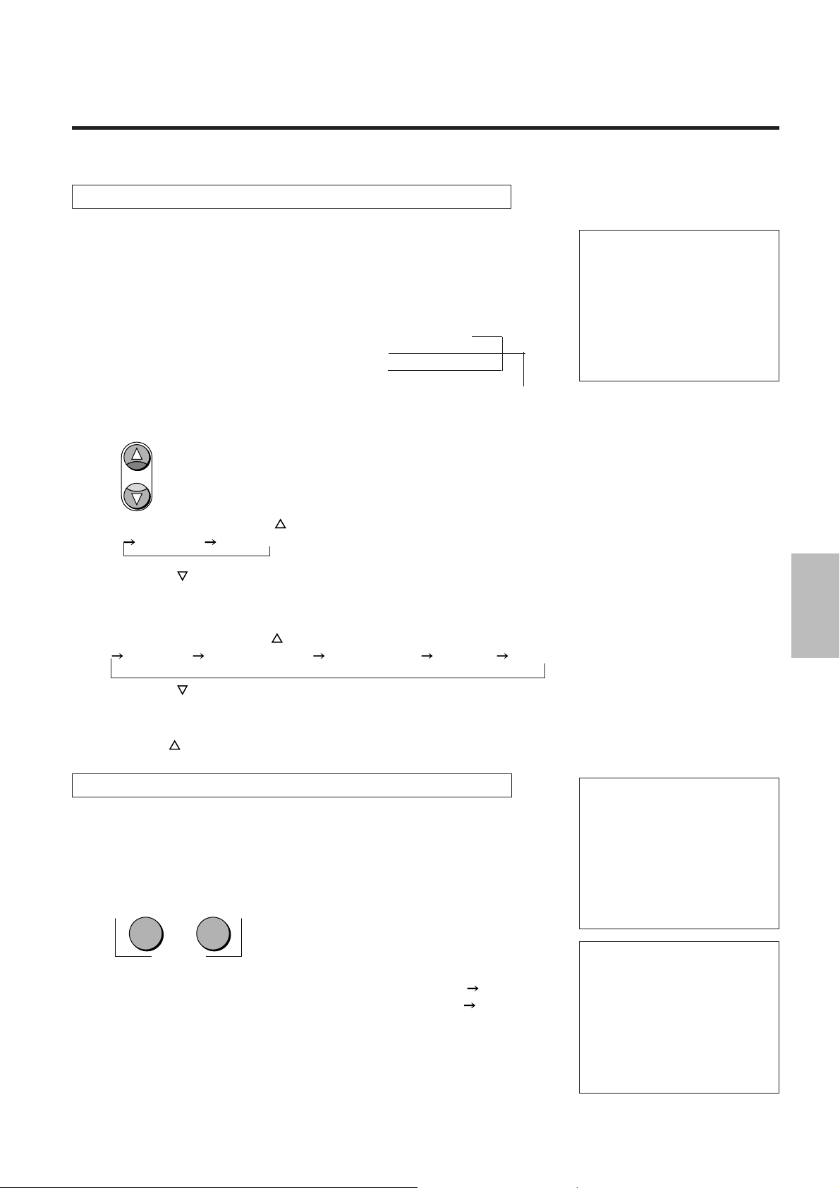
SYSTEM-ADISPLAY
-
7
INPUT 1
2345
IN1:V IDEO NTSC
OUT:DBL 525 31.5K/60
MONITOR: IN1 V IDEO
PI C. FNC COLOR +11
PICTURE FUNC. MENU
OUTPUT
FORMAT MONITOR
German
NORMAL
ENTER
CTL END
¡¡¡¡¡¡¡¡¡¡¡¡¡¡¡¡¡
REMOTE
Page 2

IPS-4000/IPS-4000Q
IPS-4000/IPS-4000Q
Image Processor
User's Manual
English
Page 3

CAUTION :
To turn off main power, be sure to remove the plug from power outlet. The power outlet socket
should be installed as near to the equipment as possible,and should be easily accessible.
REMARQUE:
Pour mettre l’appareil hors circuit, s’assurer de retirer la fiche de la prise d’alimentation. La
prise d’alimentation doit être installée aussi proche que possible de l’appareil et doit être facile
d’ accès.
WARNING
TO PREVENT FIRE OR SHOCK HAZARDS,DO NOT EXPOSE THIS UNIT TO RAIN OR
MOISTURE. ALSO DO NOT USE THIS UNIT’S POLARIZED PLUG WITH AN EXTENSION
CORD RECEPTACLE OR OTHER OUTLETS,UNLESS THE PRONGS CAN BE FULLY
INSERTED,REFRAIN FROM OPENING THE CABINET AS THERE ARE HIGH-VOLTAGE
COMPONENTS INSIDE. REFER SERVICING TO QUALIFIED SERVICE PERSONNEL.
AVERTISSEMENT
AFIN DE REDUIRE LES RISQUES D’INCENDIE OU D’ELECTROCUTION, NE PAS
EXPOSER CET APPAREIL A LA PLUIE OU A L’HUMIDITE. AUSSI, NE PAS UTILISER
LA FICHE POLARISEE AVEC UN PROLONGATEUR OU UNE AUTRE PRISE DE
COURANT SAUF SI CES LAMES PEUVENT ETRE INSEREES A FOND. NE PAS
OUVRIR LE COFFRET, DES COMPOSANTS HAUTE TENSION SE TROUVENT A
L’INTERIEUR. LAISSER A UN PERSONNEL QUALIFIE LE SOIN DE REPARER CET
APPAREIL.
2
Page 4

WARNING:
This equipment has been tested and found to comply with the limits for a Class B digital device,
pursuant to Part 15 of the FCC Rules. These limits are designed to provide reasonable
protection against harmful interference in a residential installation. This equipment generates,
uses, and can radiate radio frequency energy and, if not installed and used in accordance with
the instructions, may cause harmful interference to radio communications. However, there is
no guarantee that interference will not occur in a particular installation. If this equipment does
cause harmful interference to radio or television reception, which can be determined by turning
the equipment off and on, the user is encouraged to try to correct the interference by one or
more of the following measures:
• Reorient or relocate the receiving antenna.
• Increase the separation between the equipment and receiver.
• Connect the equipment into an outlet on a circuit different from that to which the receiver is
connected.
• Consult the dealer or an experienced radio / TV technician for help.
DOC Compliance Notice
This Class B digital apparatus meets all requirements of the Canadian Interference-Causing
Equipment Regulations.
DOC avis de conformation
Cet appareil numérique de la classe B respecte toutes les exigences du Réglement sur le
Matériel Brouilleur du Canada.
3
Page 5

1234
1234
1234
1234
1234
Warnings and Safety Precaution
The NEC IPS-4000/IPS-4000Q is designed and manufactured to provide long, trouble-free
service. No maintenance other than cleaning is required. Use a soft cloth and if necessary, mild
detergent. Do not use commercial spray cleaners which may damage the surface. In case of
damage, arrange for repairs at an authorized NEC dealer.
For operating safety and to avoid damage to the unit, read carefully and observe the following
instructions.
To avoid shock and fire hazards:
1. Provide adequate space for ventilation to avoid internal heat build-up. If you enclose the
unit in a cabinet or rack, be sure there is adequate space at the bottom of the unit to allow
heated air to rise and escape.
2. Do not use the power cord plug with extension cords or outlets unless the prongs can be
completely inserted.
3. Do not expose unit to rain or moisture.
4. Avoid damage to the power cord, and do not attempt to modify the power cord.
5. Unplug unit during electrical storms or if unit will not be used over a long period.
6. Do not open the cabinet which has potentially dangerous high voltage components inside.
If the unit is damaged in this way the warranty will be void. Moreover, there is a serious risk
of electric shock.
7. Do not attempt to service, modify, or repair the unit. NEC is not liable for any bodily harm
or damage caused if unqualified persons attempt service or open the cabinet. Refer all
service to an authorized NEC dealer.
To avoid damage and prolong operating life:
1. Use only with 100-240V 50/60Hz AC power supply. Continued operation at line voltages
other than those specified herein will shorten the life of the unit, and might even cause a fire
hazard.
2. Handle the unit carefully when moving and do not drop.
3. Locate set away from heat, excessive dust, and direct sunlight.
4. Protect the inside of the unit from liquids and small metal objects. In case of accident, unplug
the unit and have it serviced by an authorized NEC dealer.
5. Unplug unit before cleaning. Use only a soft cloth and mild detergent. Commercial
household sprays and cleaners may damage the cabinet. To turn off main power, be sure
to remove the plug from power outlet. The power outlet socket should be easily accessible.
Three types of power cords are supplied with the unit: Three-pin type for Japan, U.S.A and
Canada. Two-pin type for Germany.
For Japan
(black)
For Germany
For U.S.A.
(gray)
WARNING
Unqualified persons should under no circumstances remove the cabinet of the unit to make
internal adjustments. The warranty is void if the unit is damaged in this way. Moreover, there
is a serious risk of electric shock. If you have service difficulties, call your dealer.
4
Page 6

234
5
5
5
234
234
CONTENTS
WARNINGS AND SAFETY PRECAUTION ...............4
FEATURES ................................................................6
CHECK OF SUPPLIED ACCESSORIES...................7
POWER CABLE CONNECTIONS .............................8
PART NAMES AND FUNCTIONS
Front Panel.................................................................... 9
Setting Indicators ................................................... 11
LCD Panel ............................................................. 11
Rear Panel .................................................................. 12
Remote Control ........................................................... 14
REMOTE CONTROL NOTES
Installing the Remote Control Batteries....................... 16
Remote Control Notes................................................. 16
MAIN UNIT OPERATION
Switching On and Off the Power ................................. 17
Using the On-screen Display and the MENU Button... 17
Selection of the Input Signal........................................ 18
Selection of the Monitor Output................................... 18
Selection of the Output Signal Scanning Type............ 19
Switching On and Off Picture and Sound Muting ........ 19
SYSTEM SETTINGS
How to Bring Up the On-screen Display
and Select Items......................................................... 24
Adjustment of Sound Output Level (SOUND ATT) ..... 25
Setting of the Sync Signal Correction Function
(TBC)....................... 25
Adjustment of Y/C Signal Delay (Y/C DELAY) ............ 25
Setting of the Component Input Signal (MATRIX)....... 26
Selection of Input Signal System (VIDEO FORMAT).. 26
On/Off Switching of the On-screen Display
(DISPLAY)................ 26
On/Off Switching of the Front Panel LCD Backlight
(LCD LIGHT) ........... 26
On/Off Switching of Auto Power (AUTO POWER)...... 27
On/Off Switching of the Infrared Remote Control
(IR RMT-CTL).......... 27
Sync Signal Polarity Selection (SYNC) ....................... 27
EQUIPMENT CONNECTION EXAMPLES
Using the EXTERNAL Connector................................ 29
Using the REMOTE 1 Connector ................................ 29
Connection Examples of the REMOTE 1 Connector
with a Personal Computer............... 30
Using the REMOTE 2 Connector
(for Service personnel only) .............. 31
INSTALLATION OF RACK MOUNT FITTINGS ......32
ADJUSTMENT
Picture Adjustments .................................................... 20
Returning the Picture Adjustments to the Initial
Setting Values ........... 20
Blue Output Setting(BLUE-OUT) ........................... 20
Edge Enhancement (V-APERTURE) .......................... 21
SPECIFICATIONS ................................................... 33
PC-CONTROL COMMAND REFERENCE ..............34
LIMITED WARRANTY .............................................36
Adjustment of the Motion Detection Level (MOTION/STILL)
MOTION Adjustment ................................................... 21
Setting STILL ......................................................... 22
Adjustment of Noise Reduction (NR) .......................... 22
Splitting the Screen (SPLIT)........................................ 23
5
Page 7

1234
1234
1234
1234
1234
FEATURES
This image processor digitally processes the input video signal to reduce dot interference and
cross-color problems while improving the quality of color reproduction. The unit doubles,
quadruples the horizontal scanning frequency, doubles the fields, and converts to PC formats
(of 800 x 600 and 1024 x 768). (Model IPS-4000 doubles the horizontal scanning frequency and
doubles the fields only.) This Image processor reduces line flicker, increases the vertical
resolution, and permits a video output matched to the display region of matrix type display
devices.
Functionally adaptive 3-dimensional Y/C separation circuit greatly reduces Y
•
signal and C signal crosstalk, dot interference and cross colors.
Functionally adaptive 3-dimensional scanning line interpolation circuitwhich
•
also supports PAL and SECAM, provides a reduction of line flicker and a
smooth moving picture image quality for changing still and moving pictures
by means of the original interpolation process motion detection.
Digital video noise reduction circuit greatly improves the signal-to-noise ratio
•
of the signal and outputs an image (permitting 3-stage switching) with little
noise.
Equipped with a still picture function for the images of document cameras.
•
Equipped with a demonstration split function for switching between the
•
interlace mode and the artficial interlace mode.
One-line type TBC(Time base corrector) function increases the margin corre-
•
sponding to the VCR nonstandard signal input and reduces the horizontal
jitter at the time of VCR playback.
The higher bandwidth of the chroma signal which is due to the color transient
•
correction circuit serves to raise the resolution of the color signal.
6
Page 8
234
5
5
5
234
234
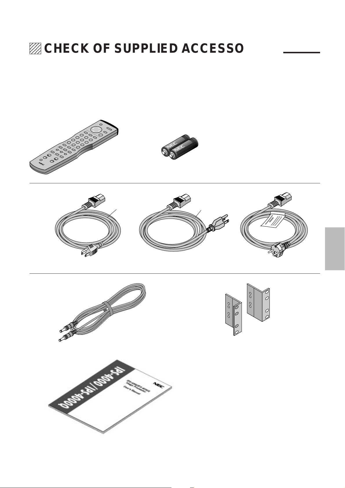
CHECK OF SUPPLIED ACCESSORIES
Check the supplied accessories after opening the carton.
If anything is missing, please contact your NEC authorized dealer.
RD324 Remote Control...1 unit AAA Batteries...2
Power Cables
Black
Gray
100 V AC 10 A (3 m) for Japan...1 125 V AC 10 A (3 m) for U.S.A....1 250 V AC 10A (3 m) for Europe...1
Remote Control Cable (4 m)...1 Rack Mount Fittings...2
User's Manual...1
7
Page 9
1234
1234
1234
1234
1234
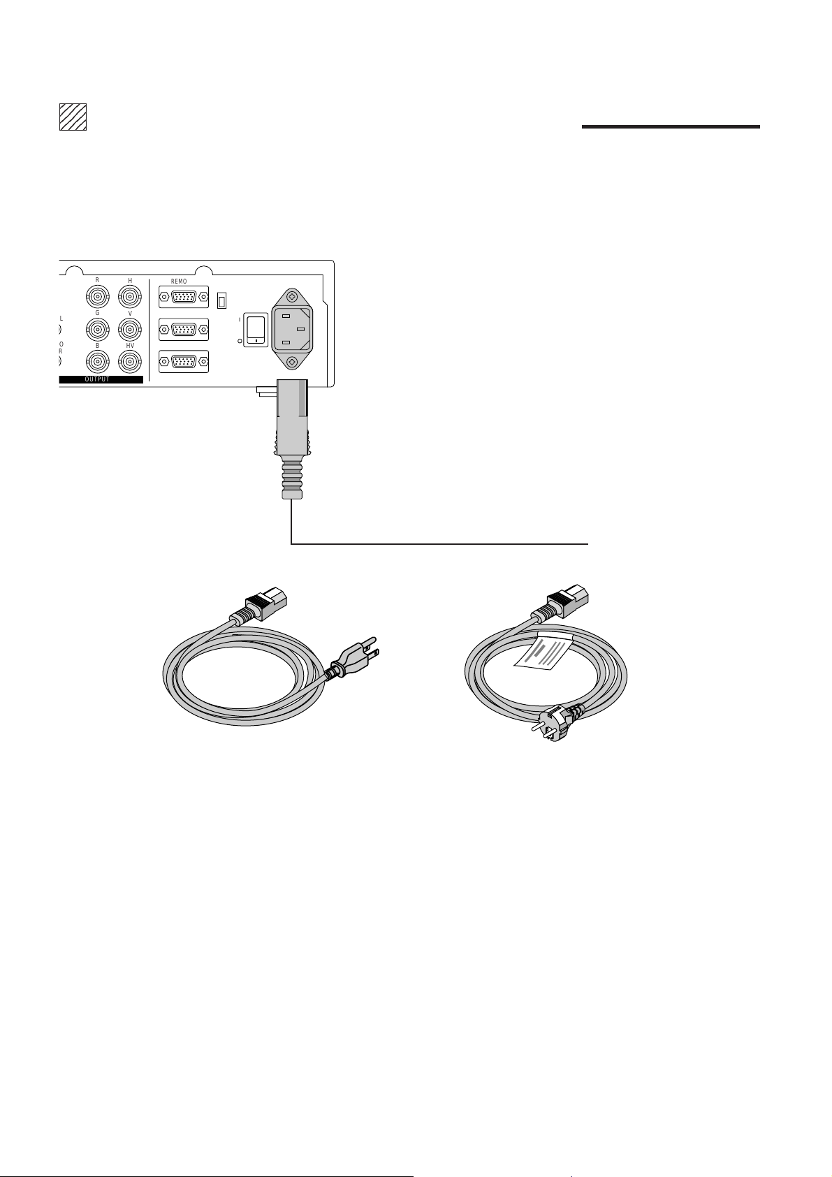
POWER CABLE CONNECTIONS
Three types of power cables are supplied with this unit. Use the type of power cable that suits the region in which the unit will be
used.
R
L
O
R
H
G
V
BHV
OUTPUT
REMOTE1
REMOTE2
EXTERNAL CONTROL
COM
SW
POWER
422
232C
AC IN
Power cable for the U.S.A. (125 V AC)
©
To the power outlet
Power cable for Europe (250 V AC)
8
Page 10
234
5
5
5
234
234
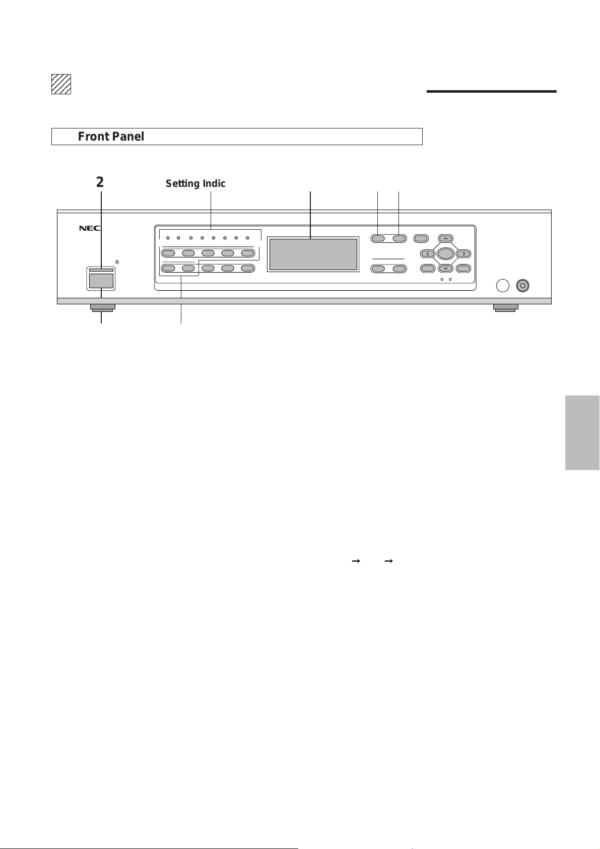
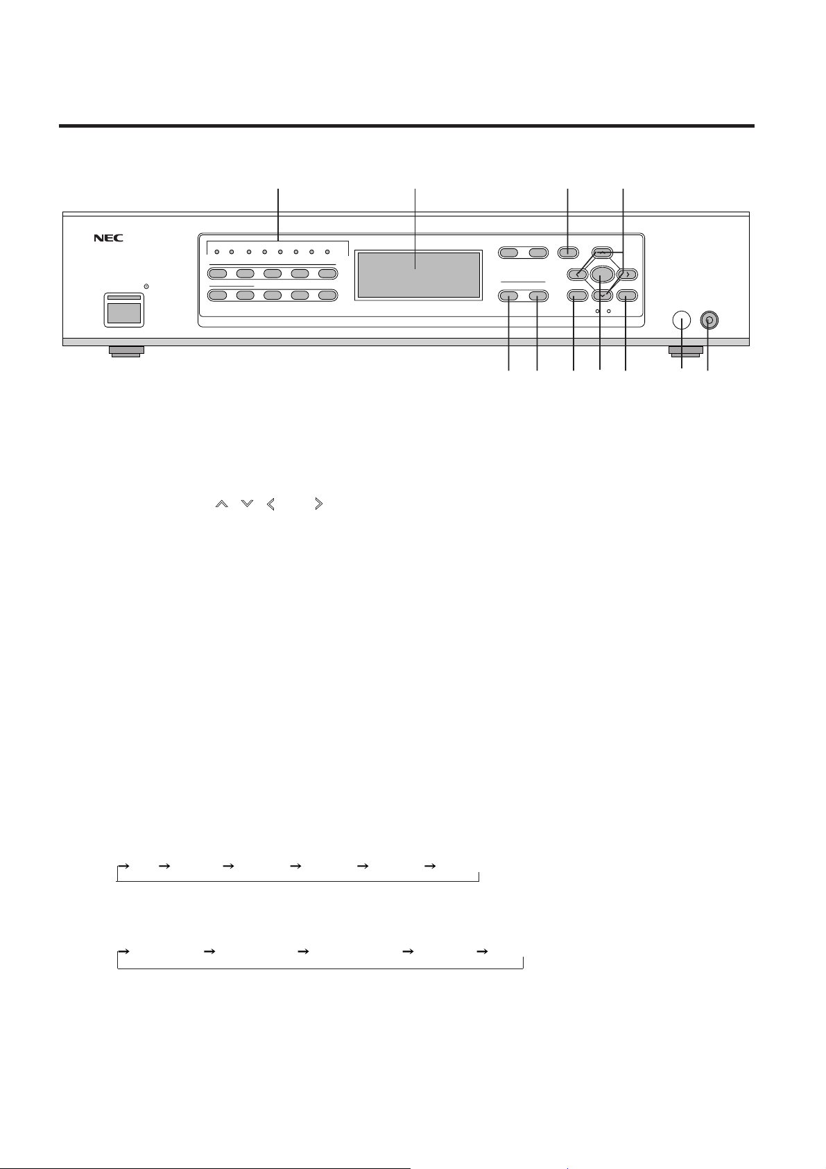
PART NAMES AND FUNCTIONS
Front Panel
2 Setting Indicators LCD Panel 45
PICTURE FUNC. MENU
OUTPUT
FORMAT MONITOR
POWER
ON/STAND-BY
IR COM EXT
1
67890
STILL SPLIT BLUE
INPUT 1
2345
SYSTEM-ADISPLAY
-
7
13
1. POWER Button
Switches the power on or off.
2. POWER Indicator
The indicator is green when the power is on. When the power is switched off, the indicator is red
and the unit enters the standby mode.
3. INPUT Buttons (1 to 7)
These are the input selection buttons. Buttons 8, 9, and 0 do not function.
NORMAL
CTL END
ENTER
REMOTE
4. PICTURE FUNC. Button
This button selects the video adjustments.
Each press advances the selection one step in the sequence of COLOR
TINT SHARPNESS.
COLOR ................... Color saturation adjustment
TINT ........................ Tint adjustment
SHARPNESS ..........Picture sharpness adjustment
NOTE: Some video adjustments cannot be selected depending on input signals.
5. MENU Button
This button selects the following adjustments: V-APERTURE, MOTION, STILL, NR, and SPLIT.
Press the button to switch between adjustments.
V-APERTURE: Selects the vertical edge correction (edge enhancement in the vertical direction)
MOTION.................. Selects the motion detection level, provides optimum picture interpolation
to the image, and prevents drops in resolution as well as noise.
STILL....................... Performs Y/C separation and picture interpolation suited to still pictures.
NR ...........................Reduces picture noise.
SPLIT ...................... Sets the artificial interlace display to half the screen or the full screen.
This is used to view the effects of the scanning line interpolation.
9
Page 11
PART NAMES AND FUNCTIONS
Setting Indicators LCD Panel 67
PICTURE FUNC. MENU
OUTPUT
FORMAT MONITOR
POWER
ON/STAND-BY
IR COM EXT
1
67890
STILL SPLIT BLUE
INPUT 1
-
2345
SYSTEM-ADISPLAY
7
14 13 12 11 10 9 8
6. NORMAL Button
Returns the image adjustment contents (COLOR, TINT, and SHARPNESS ) to the initial setting
condition.
7. CURSOR Buttons ( , , , and )
Used for the selection of the various functions and for adjustments and settings.
8. REMOTE Jack
A remote cable is connected here when the wired remote control is used.
9. Infrared Remote Control Sensor Window
The signal of the infrared remote control is received here.
NORMAL
CTL END
ENTER
REMOTE
10. END Button
Not available.
11. ENTER Button
Sets the various adjustment function selections and closes the adjustment screen.
12. CTL Button
This is a combined function button that is used in conjunction with other buttons.
13. MONITOR Button
This button selects the monitor output at the time of selecting INPUT 7 (RGB).
Each press of the button advances the selection one step in the sequence of
OFF INPUT 1 INPUT 2 INPUT 3 INPUT 4 INPUT 5 .
14. FORMAT Button
This button selects the format (resolution) of the output signal.
Each press of the button advances the selection one step in the sequence of
Line Double Field Doubler Line Quadruple 800 x 600 1024 x 768.
(Model IPS-4000 doubles the line and doubles the fields only.)
10
Page 12
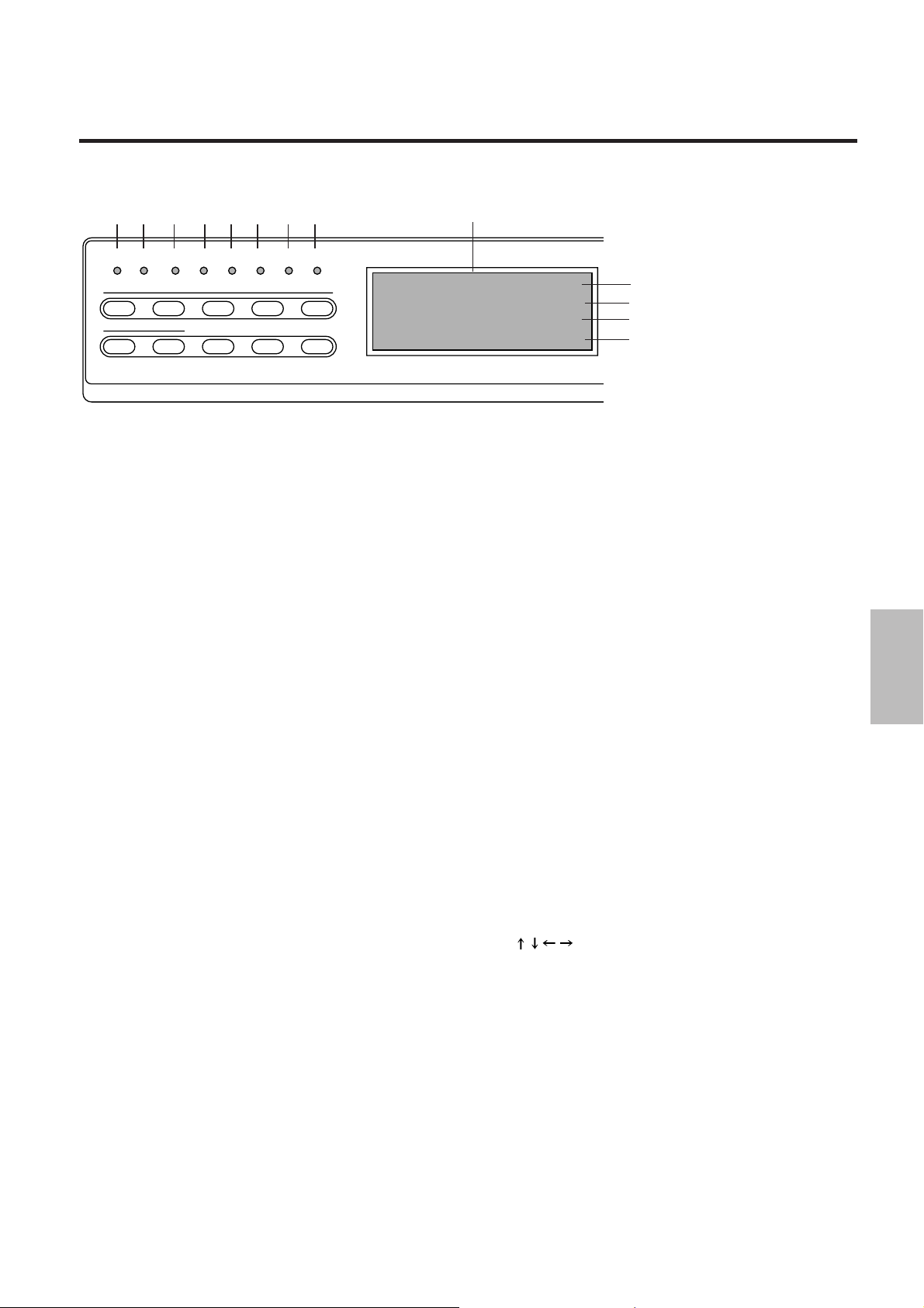
PART NAMES AND FUNCTIONS
12 3 456 78
IR COM EXT
1
67890
Setting Indicators
•
2345
STILL SPLIT BLUE
INPUT 1
-
7
1. IR (Infrared Remote Control) Indicator
Lit green: When IR-RMT-CTL of SYSTEM-B is set to "ON"
Lit red: When IR-RMT-CTL of SYSTEM-B is set to "OFF"
2. DISPLAY Indicator
Lit green: When DISPLAY of SYSTEM-B is "ON" (When
set to ON with the DISPLAY button of the remote control.)
Lit red: When OFF
3. COM (Communications) Indicator
Steadily unlit. For service personnel only.
4. EXT (External Control) Indicator
Lit green: When EXTERNAL CONTROL is "ON"
Unlit: When OFF
5. STILL Indicator
Lit green: When STILL of MENU is "ON"
Unlit: When OFF
6. SPLIT Indicator
Lit green: When SPLIT of MENU is "HALF˙ALL"
Unlit: When OFF
7. BLUE Indicator
Lit green: When B-OUT of PICTURE FUNC. is "ON"
Unlit: When off
8. SYSTEM-A Indicator
Lit green: When any of the adjustment items of SYSTEMA differ from the factory preset.
Unlit: When all of the adjustment items of SYSTEM-A are
the same as the factory preset.
SYSTEM-ADISPLAY
LCD Panel
IN1:V IDEO NTSC
OUT:DBL 525 31.5K/60
MONITOR: IN1 V IDEO
PIC.FNC COLOR +11
LCD Panel
•
First Line
Display of the format of the input signal:
Input connector number, Input signal,Video system
Second Line
Display of the format of the output signal:
Scanning system (Number of horizontal scanning lines,
Horizontal frequency, Number of field frequency)
Third Line
The input connector number that is output to MONITOR
OUT and the video type, either S-VIDEO or VIDEO
Fourth Line
Display of adjustment and setting contents
The display will go off when the setting has been exited
with the ENTER button, or when there has been no input
for about 5 seconds.
Example 1
PIC.FNC COLOR +10
The saturation of the color of the picture adjustment is set
to +10.
Example 2
SYSTEM A
When the MENU button is pressed while holding down the
CTL button to output a display of the system settings.
First line
Second line
Third line
Fourth line
11
Page 13
PART NAMES AND FUNCTIONS
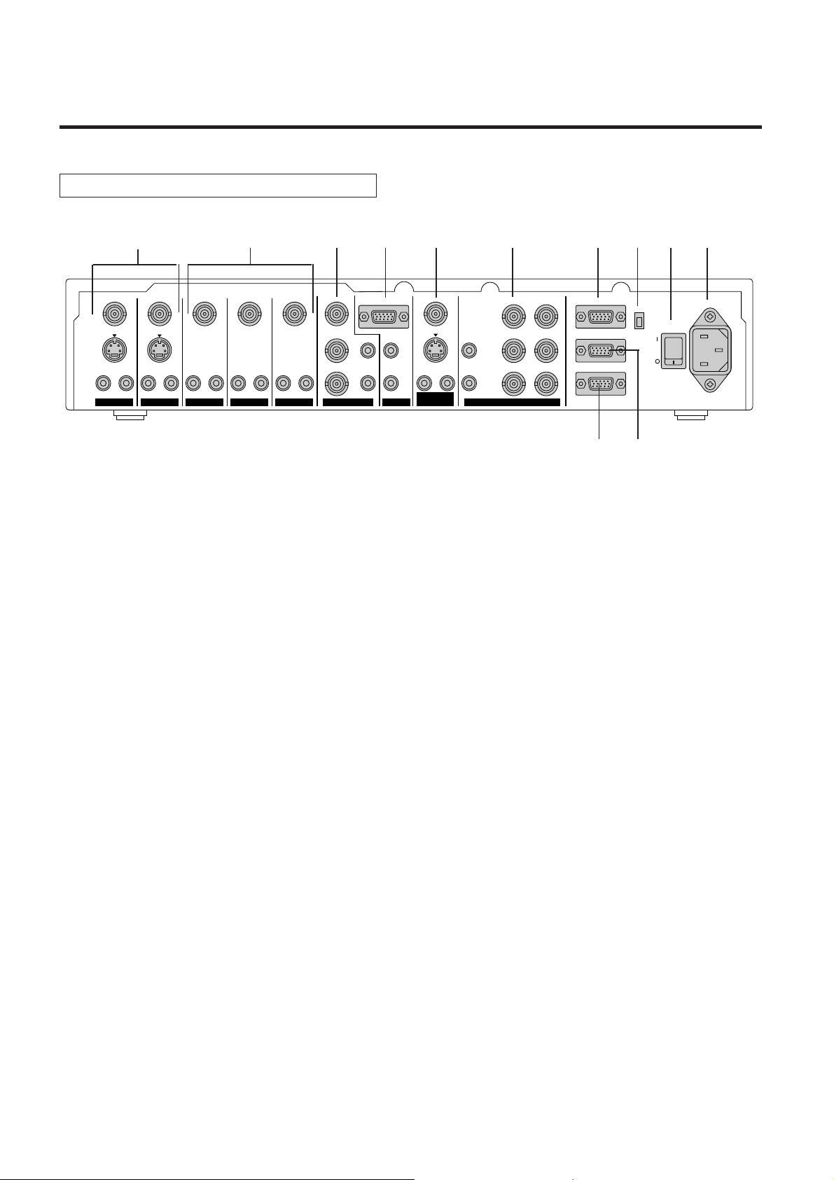
Rear Panel
12 11 10 9 8 7 4 3 2 1
L
R
VIDEO
S-VIDEO
AUDIO AUDIO
LR
MONITOR
OUTPUT
L
R
VIDEO
S-VIDEO
AUDIO
LR
VIDEO
S-VIDEO
AUDIO
LR
VIDEO
AUDIO
LR
VIDEO
AUDIO
LR
COMPONENT
VIDEO
Y
Cr
AUDIO
Cb
LLR
INPUT 5 INPUT 7
RGB
AUDIO AUDIO
R
1. AC IN Connector
The supplied power cable is connected here.
2. POWER Switch (Main Power)
Switches on and off the main power of the unit.
3. COM SWITCH
Selects the communications standard for the REMOTE 1 connector.
422 ............ RS-422 standard
232C.......... RS-232C standard
4. REMOTE 1 Connector (Mini D-Sub 15 pin)
This connector is connected with the personal computer or other control equipment.
5. REMOTE 2 Connector (Mini D-Sub 15 pin)
For service personnel only.
R
H
G
V
BHV
OUTPUTINPUT 6INPUT 4INPUT 1 INPUT 2 INPUT 3
REMOTE1
REMOTE2
EXTERNAL CONTROL
COM
SW
65
422
232C
POWER
AC IN
6. EXTERNAL CONTROL (Mini D-Sub 15 pin)
This connector is connected when operating the unit by means of external control.
See "External Control Mode"
7. OUTPUT Connectors
These connectors are connected to a monitor equipped with RGB connectors such as a multi-sync
monitor or a projector.
R, G, B (BNC type): Connected to the R, G, and B input connectors of a multi-sync monitor or
projector.
H, V (BNC type) ................ Connected to the H and B input connectors of a multi-sync monitor
or projector.
HV (BNC type) .................. Connected to the HV input connectors of a multi-sync monitor or
projector.
This is only available when any one of INPUT 1 to 6 is selected.
Note that there is no output from this connector on the RGB mode,which
means when INPUT 7 is selected.
AUDIO L, R (RCA type) .... Connected to the audio input jacks of a multi-sync monitor or projector.
12
Page 14

PART NAMES AND FUNCTIONS
8. MONITOR OUTPUT Connectors
These connectors output the selected input when input selection is INPUT 1 through 5. When input selection is
INPUT 7, the signal selected by MONITOR selection at the time of INPUT 1 through 5 or OFF can be monitored.
VIDEO (BNC type) ...............Outputs the video signal of the equipment connected to INPUT 1 through 5.
S-VIDEO (Mini DIN) .............Outputs the S-video signal of the equipment with an S-video connector connected
to INPUT 1 to 2.
Outputs the S-video signal in place of the video signal of the equipment connected
to INPUT 1 through 5 when composite connectors other than S-video connector
of INPUT 1 through 5 are used .
AUDIO L, R (RCA type) .......Outputs the audio signal of the equipment connected to INPUT 1 through 5.
9. INPUT 7 Connectors (RGB Input)
RGB (Mini D-SUB 15 Pin) ....This connector is connected with the RGB output connectors of the external
equipment. Signals input here are output from the OUTPUT connectors.
AUDIO L, R (RCA type) .......These jacks are connected with the audio output jacks of the external equipment.
Signals input here are output from the OUTPUT jacks.
10. INPUT 6 Connectors (COMPONENT Input)
Y, Cr, Cb (BNC Type) ..........These connectors are connected to the color-difference output connector of the
external equipment.
AUDIO L, R (RCA type) .......These jacks are connected with the audio output jacks of the external equipment.
11. INPUT 3, 4, 5 Connectors (VIDEO Input)
VIDEO (BNC type) ...............These connectors are connected with the video output connectors of the external
equipment.
AUDIO L, R (RCA type) .......These jacks are connected with the audio output jacks of the external equipment.
12. INPUT 1, 2 Connectors (VIDEO Input)
VIDEO (BNC type) ...............These connectors are connected with the video output connectors of the external
equipment.
S-VIDEO (Mini DIN) .............These connectors are connected with the S-video output connectors of the external
equipment.
AUDIO L, R (RCA type) ....... These jacks are connected with the audio output jacks of the external equipment.
13
Page 15
PART NAMES AND FUNCTIONS
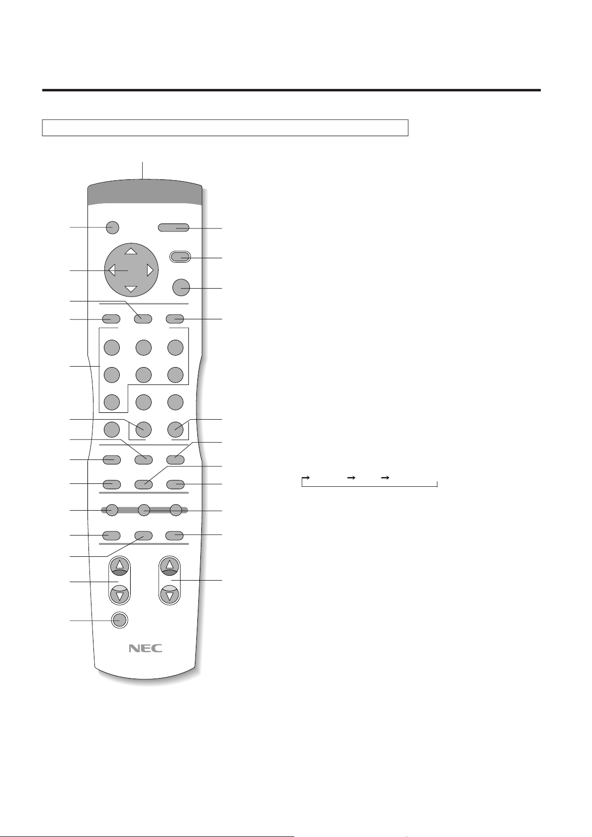
Remote Control
2
3
7
8
9
10
13
12
15
18
19
20
22
24
26
OPERATE
CURSOR
CTL
INPUT SELECT
ABC
POWER
MENU
PICTURE
FUNC.
ENTER END
DEF
GHI
123
JKL MNO PQR
456
STU
COLOR
MOTION
SPLIT R
V-APERTURE
FORMAT
VWX YZ-
7
89
PICTURE SOUND
0
SHARPNESS
STILL NR
LCD DISPLAY
NORMAL
MUTE
TINT
MONITOR
1. POWER Button
Switches the power on or off.
2. OPERATE Button
This is used in conjunction with the NEC projectors such as CRT
1
4
5
6
11
14
16
17
B
25
21
23
projectors and 3 chip DLP at the time of linked operation. (For use by
service personnel.)
3. CURSOR Button (UP, DOWN, LEFT, and RIGHT)
This is used for the adjustment and setting of the various adjustment
functions.
4. MENU Button
This button selects the adjustments of V-APERTURE, MOTION,
STILL, NR, and SPLIT. Each press switches the menu.
V-APERTURE ......Adjusts the edge enhancement.
MOTION...............Selects the motion detection level, provides
optimum picture interpolation to the image, and
prevents drops in resolution as well as noise.
STILL....................Performs Y/C separation and picture inter-
polation suited to still pictures.
NR ........................Reduces picture noise.
SPLIT ................... Sets the artificial interlace display to half the
screen or the full screen. This is used to view the
effects of the scanning line interpolation.
5. PICTURE FUNC. Button
This button selects the picture adjustments.
Each press advances the selection one step in the sequence of
COLOR TINT SHARPNESS .
COLOR ................Color saturation adjustment
TINT .....................Tint adjustment
SHARPNESS .......Picture sharpness adjustment
6. END Button
For service personnel only.
7. ENTER Button
Sets the various adjustment function selections and closes the
adjustment screen.
8. CTL Button
This is a combined function button that is used in conjunction with
other buttons.
9. INPUT SELECT Buttons
These are the input selection buttons.
Buttons 8, 9, and 0 do not have a function. For service personnel only.
10. PICTURE MUTE Button
Switches the video output on and off.
11. SOUND MUTE Button
Switches the audio output on and off.
12. COLOR Button
Adjusts the saturation of the color.
14
Page 16
13. SHARPNESS Button
Adjusts the sharpness of the image quality.
14. TINT Button
Adjusts the tint.
15. MOTION Button
Selects the motion detection level and provides picture interpolation to the image.
Each press of the button advances the selection one step in the sequence of
<Still>
-2 -1 0 +1 +2 <Moving>.
16. STILL Button
Performs Y/C separation and scanning line interpolation suited to still pictures.
Each press advances the selection one step between ON
OFF.
17. NR Button
Used to reduce picture noise.
Each press advances the selection one step in the sequence of
OFF 1 2 3.
18. SPLIT Button
Sets the artificial interlace display to half the screen or the full screen. This is used to view the effects
of the scanning line interpolation.
Each press of the button advances the selection one step in the sequence of
OFF HALF ALL.
PART NAMES AND FUNCTIONS
The unit should normally be used with this setting OFF.
19. V-APERTURE Button
Adjusts edge enhancement in the vertical direction.
Each press of the button advances the selection one step in the sequence of
0 1 2 3 4 5 6 7.
20. LCD Button
Switches on and off the LCD's back light. Each press advances the selection one step between
ON
OFF.
21. DISPLAY Button
Switches the on-screen display on and off. Each press advances the selection one step between
ON
OFF.
22. FORMAT Button
This button selects the format (resolution) of the output signal.
Each press of the button advances the selection one step in the sequence of
Double lines Double field Quadruple lines 800 x 600 1024 x 768.
(Model IPS-4000 doubles the lines and doubles the fields only.)
23. MONITOR Button
This button selects the monitor output at the time of selecting INPUT 7.
Each press of the button advances the selection one step in the sequence of
OFF INPUT 1 INPUT 2 INPUT 3 INPUT 4 INPUT 5 .
24. NORMAL Button
Returns the image adjustment contents (COLOR, TINT, and SHARPNESS) to the initial setting
condition.
25. R, B Buttons
Used only for linked operation. (For service personnel only.)
26. Remote Control Jack
Insert the piug of the supplied remote cable here when the remote control is used in the wired
application.
15
Page 17
1234
1234
1234
1234
1234
REMOTE CONTROL NOTES
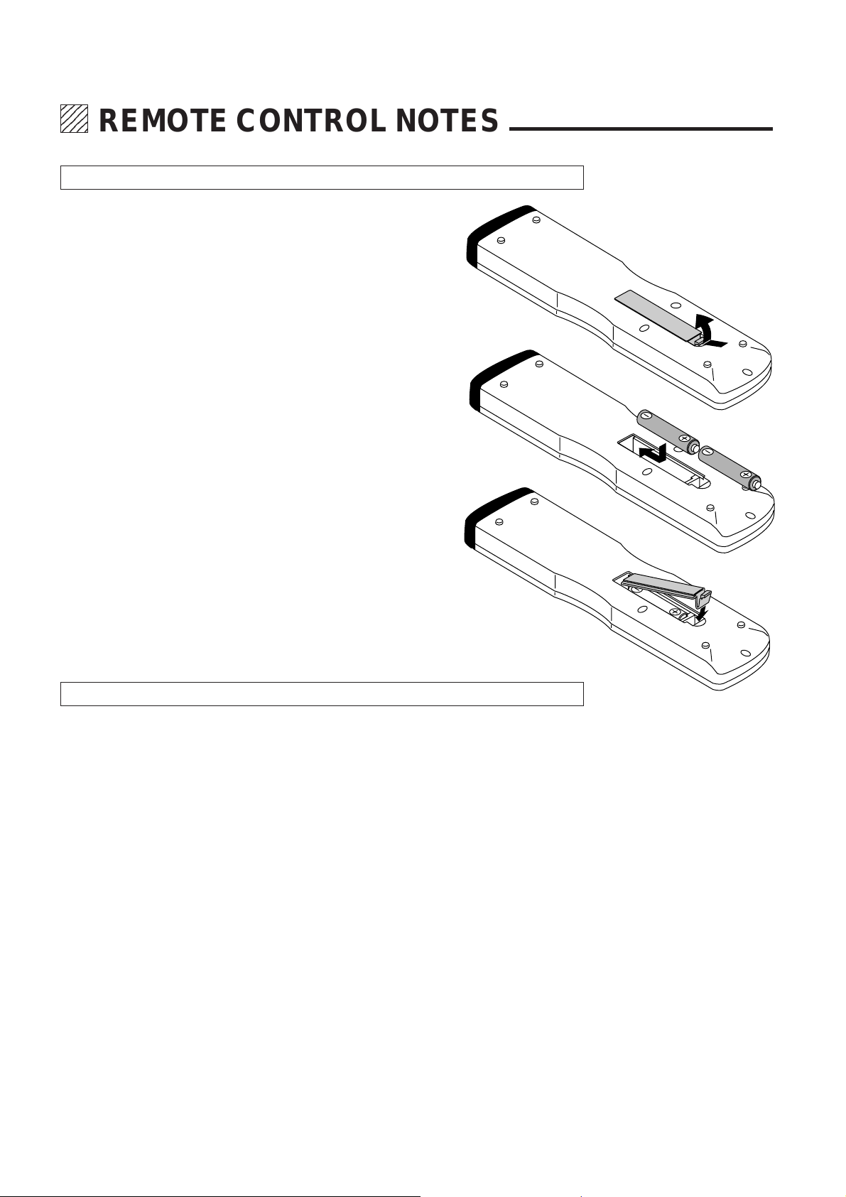
Installing the Remote Control Batteries
When it comes time to replace the batteries, two "AAA" type will be
required.
1. Press and open the cover.
2. Align the batteries according to the (+) and (-)
indications inside the case.
3. Replace the cover.
Remote Control Notes
Use the remote control within a distance of about 7 m and at an angle of 30° above, below,
•
to the left and to the right of the remote control sensor located at the front of the main unit.
The remote control system may not function when direct sunlight or strong illumination strikes
•
the remote control sensor of the main unit, or when there is an obstacle in the path.
When remote control buttons are pressed and held, main unit operations may not be possible.
•
Do not subject to strong shock.
•
Do not allow water or other liquid to splash on the remote control. If the remote control gets
•
wet, wipe it dry immediately.
Avoid exposure to heat and steam.
•
Remove the batteries from the remote control when the remote control is not going to be used
•
for a long period.
16
Page 18
234
5
5
5
234
234
MAIN UNIT OPERATION
Connect input equipment as well as output equipment such as projectors prior to
operation. In this section, the following will be described: switching on and off the
power, on-screen displays used in adjustments and settings and their method of
use, selection of input equipment, selection of monitor output and scanning types,
and the muting of picture and sound.
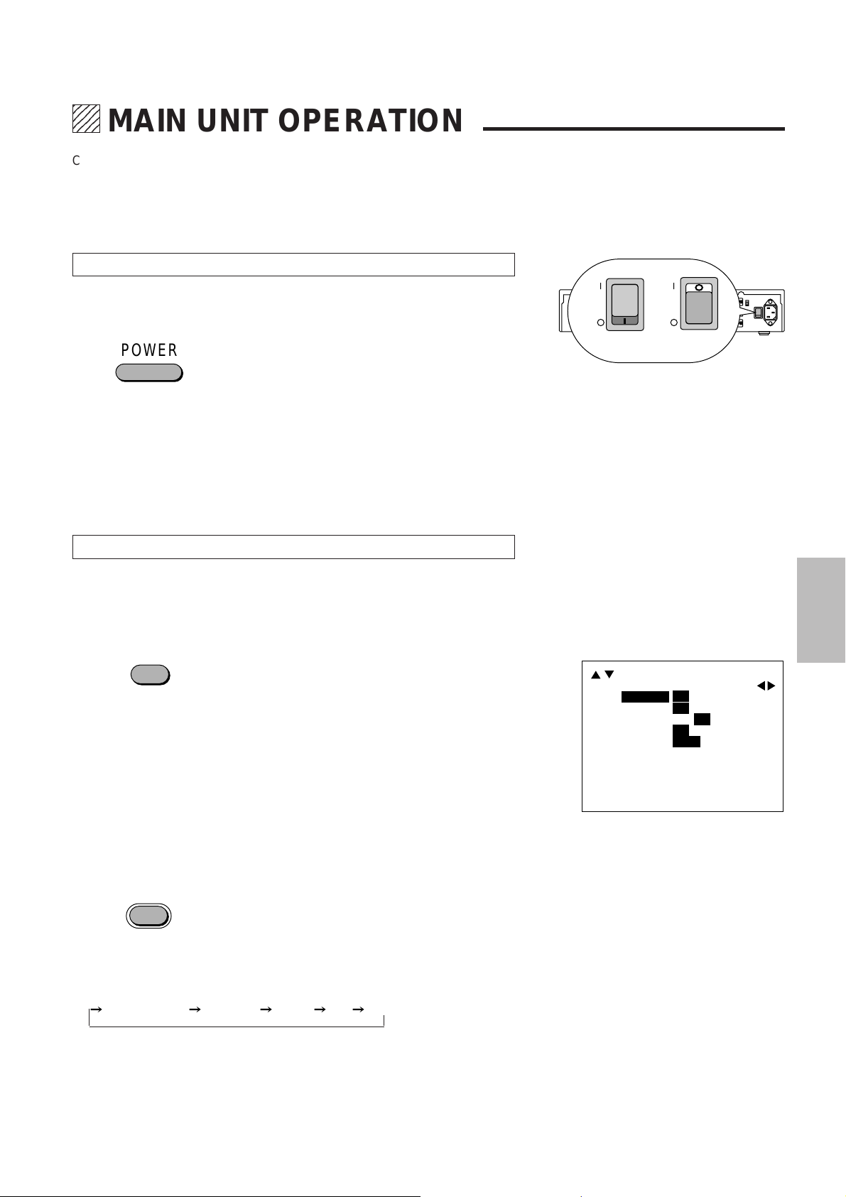
Switching On and Off the Power
Setting the POWER switch located on the rear panel of the main unit to "ON" puts
the unit into the standby mode. The power can then be switched on and off with
the front panel POWER button or the remote control POWER button.
POWER
The POWER indicator will light green when the power is switched "ON".
The POWER indicator will light red when the power is switched "OFF" and the unit
will enter the standby mode.
To switch off the main power, set the POWER switch located on the rear panel
of the main unit to "OFF".
Notice
When the Auto Power function (described on Page 27) has been set, the unit can
be started up simply by switching on the main power.
Using the On-screen Display and the MENU Button
Switching the On-screen Display On and Off
This selection determines whether or not the displays for adjustment of the unit
and the settings are output from the OUTPUT connectors.
<Remote Control Only>
DISPLAY
Each press of the DISPLAY button advances the setting of the on-screen output
between ON and OFF. The DISPLAY indicator of the main unit will be lit to indicate
that this function is ON.
When an operation is performed, notification is provided on the on-screen
display. Press the ENTER button to get rid of the display. (The displayed
information will automatically disappear when there has not been a button
operation for about 5 seconds.)
The on-screen display is not output from the MONITOR OUTPUT connector.
•
Note also that for signals input to INPUT 7 (RGB), the on-screen display will not
be output from the OUTPUT connector.
POWER
POWER
When ON When OFF
The description will be explained when
the on-screen display is ON.
This may vary somewhat from the
display method of the main unit display window.
SYSTEM B
SYNC
[
DBL
ON OFF
ON OFF
ON OFF
ON OFF
-V-
H
]
H+V- H+V
H-V
+
+
DISPLAY
LCD LIGHT
AUTO POWER
IR RMT-CTL
Using the MENU Button
MENU
Use the MENU button when making settings of V-APERTURE, MOTION, STILL,
NR, and SPLIT.
A press of the MENU button will bring up the on-screen display and each
subsequent press advances the selection one step in the sequence of
V-APERTURE MOTION STILL NR SPLIT.
See the various descriptions for information about the setting method.
A press of the MENU button while the CLT button is being held down will set the
SYSTEM setting mode and the on-screen display will be output.
See the method of making system settings of this setting method.
17
Page 19
MAIN UNIT OPERATION
Selection of the Input Signal
These buttons select the equipment connected to the INPUT connectors of this
unit.
INPUT SELECT
ABC
DEF
GHI
123
JKL MNO PQR
456
STU
7
Select the input equipment by pressing the main unit INPUT buttons 1 through 7.
(Buttons 8, 9, and 0 do not have a function.)
When INPUT 7 (RGB) has been selected, the output from the MONITOR
OUTPUT connector will permit selection of INPUT 1 through 5 and OFF with the
MONITOR button.
When a selection has been made, the information will be displayed on screen for
about 5 seconds.
INPUT1 S-VIDEO
Selection of the Monitor Output
The selection of the input equipment, which is output from the MONITOR
OUTPUT connectors when INPUT 7 (RGB) has been selected, will be the
selection of the monitor output.
<Remote Control Operation>
MONITOR
Each press of the MONITOR button
the sequence of OFF
INPUT 1 INPUT 2 INPUT 3 INPUT 4 INPUT 5 ,
and the signal is output from the MONITOR OUTPUT connectors. Each press of
the
button moves one step in the reverse direction.
<Main Unit Operation>
Main unit operations are the same as the operations of the remote control
MONITOR button
part.
Table of Output to the MONITOR OUTPUT Connector when 7 Is Selected
Input Signal MONITOR OUTPUT
VIDEO Input S-VIDEO Input VIDEO Output S-VIDEO Output
INPUT 1-5*
INPUT 1, 2*
3
-
1
-
INPUT S1,S2*2INPUT S1,S2*
INPUT S1,S2*1INPUT S1,S2*
part advances the selection one step in
INPUT1-5 INPUT 1-5*
2
INPUT S1,S2
1
INPUT S1,S2
3
INPUT1
INPUT3
INPUT2
INPUT5
INPUT4
INPUT6 MONITOR
OUTPUTINPUT7
OUTPUT
*2The S-VIDEO input signal of INPUT 1 and 2
will be output from the monitor output VIDEO
connectors.
3
*
The VIDEO input signals of INPUT 1 through
5 will also be output from the S-VIDEO connector of the monitor output.
*1 The S-VIDEO jack will be given priority for equipment to which a VIDEO input
signal and an S-VIDEO signal have been connected at the same time.
18
Page 20
Selection of the Output Signal Scanning Type
PICTURE SOUND
MUTE
This function converts the format (resolution) of the input signal and provides
output.
When a selection has been made, the information will be displayed on screen for
a while.
DOUBLER:............Line double sequential scanning method
FIELD DOUBLER .Field double interlaced scanning method
QUADRUPLER: ....Line quadruple sequential scanning method
800 x 600 ..............Sequential scanning method
1024 x 768 ............ Sequential scanning method
MAIN UNIT OPERATION
OUTPUT DOUBLER
Model IPS-4000
<Remote Control Operation>
Each press of the FORMAT button
between
Each press of the
FORMAT
part advances the selection one step
DOUBLER FIELD DOUBLER.
button moves one step in the reverse direction.
Model IPS-4000Q
<Remote Control Operation>
Each press of the FORMAT button
DOUBLER FIELD DOUBLER QUADRUPLER 800 x 600 1024 x 768.
Each press of the
<Main Unit Operation>
Main unit operations are the same as the operations of the remote control
FORMAT button
button moves one step in the reverse direction.
part.
part advances the selection one step in the sequence of
Switching On and Off Picture and Sound Muting
(IPS-4000Q only)
These functions are used to temporarily switch off the picture or sound.
When a selection has been made, the information will be displayed on screen for
five seconds.
<Remote Control Operation Only>
Each press of the PICTURE button switches the selection between ON
Each press of the SOUND button switches the selection between ON
PICTURE MUTE
OFF.
OFF.
SOUND MUTE
19
Page 21
1234
1234
1234
1234
1234
ADJUSTMENT
Picture Adjustments
COLOR (i.e., saturation of colors), TINT and SHARPNESS (i.e., sharpness of
picture quality), can be adjusted and output.
When the input channel is set to INPUT 6 (COMPONENT), adjustment of TINT
is not permitted. Also note that when the input signal is a black-and-white signal,
only the SHARPNESS adjustment is permitted.
<Main Unit Operation>
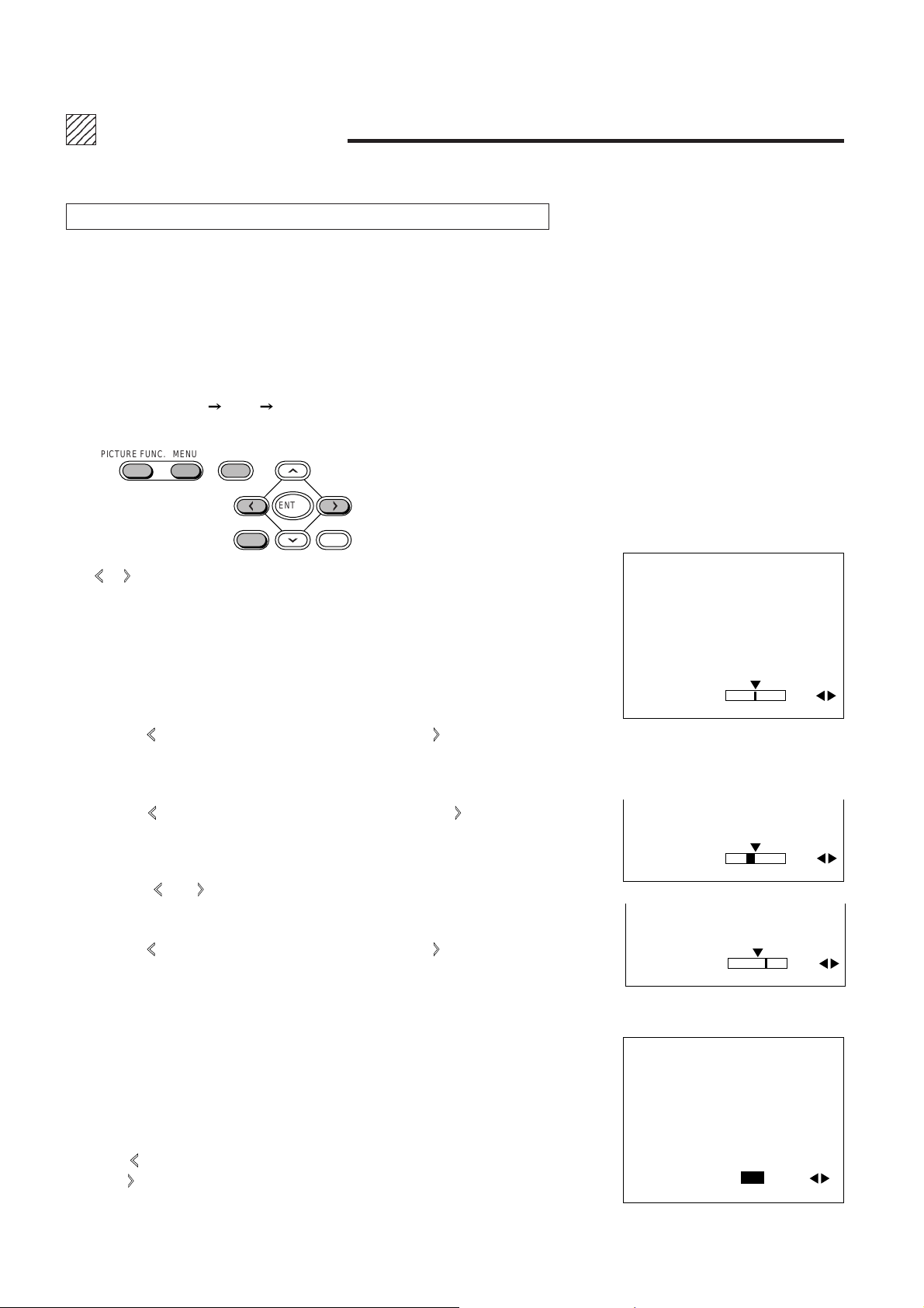
Each press of the PICTURE FUNC. button advances the selection one step in the
sequence of COLOR
appear. Bring up the desired adjustment indication on the on-screen display.
TINT SHARPNESS. The on-screen display will
PICTURE FUNC. MENU
The
or button permits adjustment in 49 steps from -24 to 0 to +24. About 5
seconds after the adjustment, the on-screen display will go off.
Depending on the format of the input signal, adjustment of some functions might
not be possible. The on-screen display will not appear for items that cannot be
adjusted.
COLOR (Color Saturation Adjustment)
•
Pressing the button makes the color thinner, pressing the button makes the
color deeper.
TINT (Tint Adjustment)
•
Pressing the button makes the video more red, pressing the button makes
the video greener.
Press the button on the remote control which you want to adjust. The on-screen
display of the information associated with that button appears. Make the adjust-
ment with the and CURSOR buttons.
NORMAL
ENTER
CTL END
PICTURE FUNCTION
COLOR 00
PICTURE FUNCTION
TINT R03
SHARPNESS (Picture Quality Sharpness Adjustment)
•
Pressing the button makes the color thinner, pressing the button makes the
color deeper.
Returning the Picture Adjustments to the Initial Setting Values
•
A press of the NORMAL button will return to zero level (initial value) the
adjustments of COLOR, SHARPNESS, and TINT.
Blue Output Setting (BLUE-OUT)[For service personnel only]
•
When set to ON, output will be only from the B (blue) OUTPUT connector.
The BLUE-OUT display is set by selecting TINT and pressing the CTL button and
the MENU button at the same time while the on-screen display is being shown.
Press the
press the
A press of the ENTER button will return to the TINT adjustment screen.
button of the CURSOR and select ON. To switch off the function,
button and select OFF.
20
PICTURE FUNCTION
SHARPNESS
BLUE OUT ON/OFF
{
03
Page 22
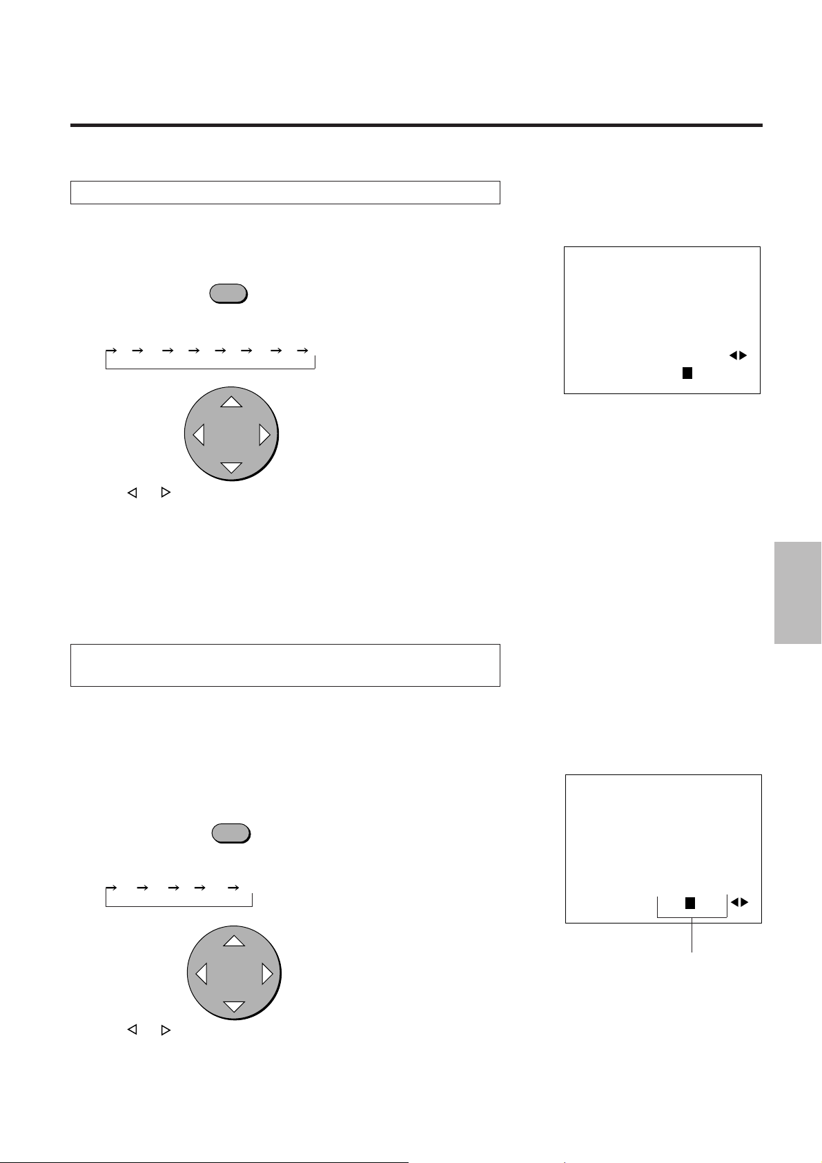
Edge Enhancement (V-APERTURE)
This adjusts the edge enhancement.
<Remote Control Operation>
V-APERTURE
A press of the V-APERTURE button displays V-APERTURE directly on screen.
Each press of the button advances the selection one step in the sequence of
0 1 - 2 3 4 5 6 7.
CURSOR
Press the or CURSOR button and adjust to the desired level.
At level 0, V-APERTURE will be switched off, and as the level number gets larger
the effect will become stronger.
Press the ENTER button to make the display go off.
ADJUSTMENT
MENU
V-APERTURE 0 1 2 3 4 5 6 7
<Main Unit Operation>
A press of the MENU button will bring up the on-screen display. Press the MENU
button until V-APERTURE is displayed. Level adjustment is the same as with the
remote control.
Adjustment of the Motion Detection Level
(MOTION/STILL)
This function sets the picture interpolation method. Please select a level that suits
the image such as one with a lot of motion or a still image.
Normally, level 0 is used.
MOTION Adjustment
•
<Remote Control Operation>
MOTION
A press of the MOTION button displays MOTION directly on screen.
Each press advances the selection one step in the sequence of
-2 -1 0 +1 +2.
CURSOR
MENU
MOTION -2 -1 0 +1 +2
This part will become red when MOTION
selection is not possible.
Press the
In the direction of
In the direction of + ....... Suited to images with fast motion.
or CURSOR button and adjust to the desired level.
- ......
Suited to still pictures.
21
Page 23

ADJUSTMENT
<Main Unit Operation>
A press of the MENU button will bring up the on-screen display. Press the MENU
button until MOTION is displayed. Level adjustment is the same as with the remote
control.
CAUTION
Adjustment will not be possible when STILL or SPLIT is set to ON. The priority order
of settings is SPLIT, STILL, and MOTION. In view of this, switch other settings to OFF
when setting MOTION.
Setting STILL
•
<Remote Control Operation>
STILL
A press of the STILL button displays STILL directly on screen.
Each press of the STILL button switches the selection between ON OFF.
CURSOR
MENU
STILL ON
/
OFF
Press the CURSOR button and select ON.
To cancel, select OFF.
A press of the ENTER button will make the display go off.
<Main Unit Operation>
A press of the MENU button will bring up the on-screen display. Press the MENU
button until STILL is displayed. On/Off switching is the same as with the remote
control.
NOTE
Adjustment will not be possible when SPLIT is set to ON. The priority order of
settings is SPLIT, STILL, and MOTION. In view of this, switch SPLIT to OFF.
Adjustment of Noise Reduction (NR)
This function reduces the screen noise.
<Remote Control Operation>
NR
A press of the NR button displays NR directly on screen.
Each press advances the selection one step in the sequence of
OFF 1 2 3.
CURSOR
MENU
NR OFF 1 2 3
Press the
The NR effect increases as the numbers get larger.
A press of the ENTER button will make the display go off.
or CURSOR button and select the desired level.
22
Page 24

<Main Unit Operation>
A press of the MENU button will bring up the on-screen display. Press the MENU
button until NR is displayed. The selection method is the same as with the remote
control.
Splitting the Screen (SPLIT)
This function sets the artificial interlace display to half the screen or the full screen.
This is used to view the effects of the scanning line interpolation.
The unit should normally be used with this setting OFF.
NOTE
The adjustment for motion detection level (MOTION / STILL) is not available.
This function is available only when the output format is DOUBLER. The onscreen display does not appear except when the output format is DOUBLER.
<Remote Control Operation>
SPLIT R B
ADJUSTMENT
A press of the SPLIT button displays SPLIT directly on screen.
Each press advances the selection one step in the sequence of
OFF HALF ALL.
CURSOR
Press the
<Main Unit Operation>
A press of the MENU button will bring up the on-screen display. Press the MENU
button until SPLIT is displayed. The selection method is the same as with the
remote control.
or CURSOR button and select.
MENU
SPLIT OFF HALF ALL
23
Page 25

1234
1234
1234
1234
1234
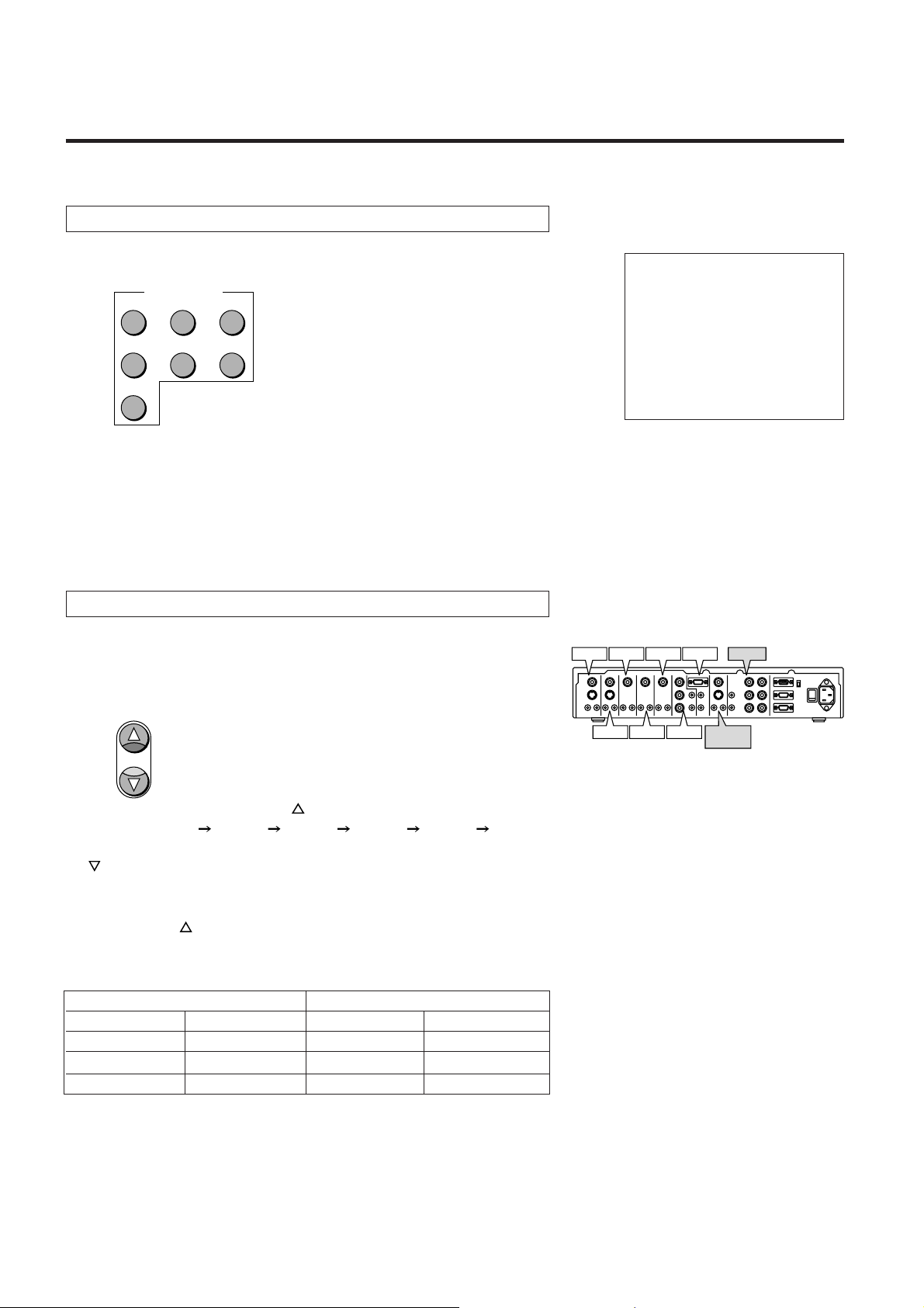
SYSTEM SETTINGS
How to Bring Up the On-screen Display and
Select Items
CURSOR
MENU
CTL ENTER END
Press the MENU button while holding down the CTL button to display the on-
1.
screen menu of system settings.
2.
Press the
or CURSOR button and select SYSTEM A or SYSTEM B.
SYSTEM A Items
SOUND ATT ........... Sound output level adjustment.
TBC ......................... Turning on or off time base corrector.
Y/C DELAY ............. Y/C signal delay adjustment.
MATRIX .................. Setting of the component input signal.
VIDEO FORMAT..... Selection of the input signal system.
SYSTEM B Items
DISPLAY ................. Switches the on-screen display on and off.
LCD LIGHT ............. Switches the LCD backlight of the main unit on and off.
AUTO POWER ....... This setting automatically starts up the unit when the main
power is switched on.
IR RMT-CTL............ This setting determines whether or not the signal from the
remote control is received.
SYNC ...................... This sets the output polarity of the sync signal.
SYSTEM A
SOUND ATT
TBC
ON OFF
Y
/
C DELAY
MATRIX
VIDEO FORMAT
-2 -
1 0 +1+2
Cr/Cb
R-Y
/
B-Y Pr/Pb
AUTO NTSC
4.43NTSC PAL
SECAM
(Factory Default Settings)
SYSTEM B
SYNC
[
DBL
ON OFF
ON OFF
ON OFF
ON OFF
-V-
H
]
H+V- H+V
H-V
DISPLAY
LCD LIGHT
AUTO POWER
IR RMT-CTL
(Factory Default Settings)
00
+
+
Desired items are selected with the
3.
and buttons of the cursor.
24
The currently set scanning system is displayed.
SYSTEM A
1 0 +1+2
/
B-Y Pr/Pb
00
SOUND ATT
TBC
Y/C DELAY
MATRIX
VIDEO FORMAT
ON OFF
-2 -
Cr/Cb
R-Y
AUTO NTSC
4.43NTSC PAL
SECAM
Page 26

4.
The or CURSOR button is used to determine the setting of the
contents
5.
Press the ENTER button to exit. In the absence of key input, the on-screen
display will go out in about 5 seconds.
Adjustment of Sound Output Level (SOUND ATT)
SYSTEM A
SOUND ATT
TBC
Y/C DELAY
MATRIX
VIDEO FORMAT
SYSTEM SETTINGS
1 0 +1+2
/
B-Y Pr/Pb
00
ON OFF
-2 -
Cr/Cb
R-Y
AUTO NTSC
4.43NTSC PAL
SECAM
This function adjusts the level of the audio signal.
Select SOUND ATT of SYSTEM A, then press the
or CURSOR button and
adjust to the desired level.
The adjustment range is from -48 to 0.
Setting of the Time Base Corrector Function
This function turns on or off the time base corrector.
Select TBC of SYSTEM A, then press the
or CURSOR button and select
the desired contents.
ON................Time base correction ON
OFF .............. Time base correction OFF
Adjustment of Y/C Signal Delay (Y/C DELAY)
(TBC)
SYSTEM A
SOUND ATT
TBC
Y
/
C DELAY
MATRIX
VIDEO FORMAT
SYSTEM A
SOUND ATT
TBC
Y
/
C DELAY
MATRIX
VIDEO FORMAT
ON OFF
-2 -
1 0 +1+2
Cr
/
Cb
R-Y
/
B-Y Pr/Pb
AUTO NTSC
4.43NTSC PAL
SECAM
ON OFF
-2 -
1 0 +1+2
Cr/Cb
R-Y
/
B-Y Pr/Pb
AUTO NTSC
4.43NTSC PAL
SECAM
00
00
This function adjusts the delay of the Y/C signal.
Select Y/C DELAY of SYSTEM A, then press the
adjust to the desired level.
or CURSOR button and
25
SYSTEM A
SOUND ATT
TBC
Y
/
C DELAY
MATRIX
VIDEO FORMAT
ON OFF
-2 -
/
Cr
R-Y/B-Y Pr/Pb
AUTO NTSC
4.43NTSC PAL
SECAM
00
1 0 +1+2
Cb
Page 27

SYSTEM SETTINGS
Setting of the Component Input Signal (MATRIX)
This function sets the component input signal(INPUT 6).
Select MATRIX of SYSTEM A, then press the
select the desired input signal.
or CURSOR button and
SYSTEM A
SOUND ATT
TBC
Y
/
C DELAY
MATRIX
VIDEO FORMAT
1 0 +1+2
Cb
/
B-Y Pr/Pb
00
ON OFF
-2 -
/
Cr
R-Y
AUTO NTSC
4.43NTSC PAL
SECAM
Selection of Input Signal System
(VIDEO FORMAT)
This is the setting of the video input signal system.
(This should normally be set to AUTO.)
Select VIDEO FORMAT of SYSTEM A, then press the
or CURSOR button
and select the desired video signal system.
On/Off Switching of the On-screen Display
(DISPLAY)
This setting switches the on-screen display on and off.
Select DISPLAY of SYSTEM B, then press the
set to ON or OFF.
On/off switching is also permitted by the DISPLAY button of the remote control.
or CURSOR button and
SYSTEM A
SOUND ATT
TBC
Y
/
C DELAY
MATRIX
VIDEO FORMAT
SYSTEM B
DISPLAY
LCD LIGHT
AUTO POWER
IR RMT-CTL
SYNC
[
DBL
ON OFF
-2 -
1 0 +1+2
/
Cb
Cr
R-Y
/
B-Y Pr/Pb
AUTO NTSC
4.43NTSC PAL
SECAM
ON OFF
ON OFF
ON OFF
ON OFF
H
-V-
H-V
]
H+V- H+V
00
+
+
On/Off Switching of the LCD Panel Backlight
(LCD LIGHT)
This setting switches the backlight of the LCD on and off.
Select LCD LIGHT of SYSTEM B, then press the
set to ON or OFF.
or CURSOR button and
26
SYSTEM B
DISPLAY
LCD LIGHT
AUTO POWER
IR RMT-CTL
SYNC
[
DBL
ON OFF
ON OFF
ON OFF
ON OFF
-V-
H
]
H+V- H+V
H-V
+
+
Page 28

On/Off Switching of Auto Power (AUTO POWER)
SYSTEM SETTINGS
This setting automatically starts up the unit when the power is switched on.
Select AUTO POWER of SYSTEM B, then press the
or CURSOR button
and set to ON or OFF.
ON................Power will be switched on when the main power switch on the rear
panel of the main unit is "ON".
OFF .............. Power will be set to the standby mode when the main power switch
on the rear panel of the main unit is "ON".
On/Off Switching of the Infrared Remote Control
(IR RMT-CTL)
This function sets whether or not to receive the infrared signal from the wireless
remote control.
Select IR RET-CTL of SYSTEM B, then press the
or CURSOR button and
set to ON or OFF.
Sync Signal Polarity Selection (SYNC)
SYSTEM B
DISPLAY
LCD LIGHT
AUTO POWER
IR RMT-CTL
SYNC
[
DBL
SYSTEM B
DISPLAY
LCD LIGHT
AUTO POWER
IR RMT-CTL
SYNC
[
DBL
ON OFF
ON OFF
ON OFF
ON OFF
H
-V-
]
H+V- H+V
ON OFF
ON OFF
ON OFF
ON OFF
H
-V- H-V+
]
H+V- H+V+
H-V
+
+
This function sets the polarity of the output signal.
Select SYNC of SYSTEM B, then press the
or CURSOR button and select
the polarity of the desired sync signal.
SYSTEM B
SYNC
[
DBL
ON OFF
ON OFF
ON OFF
ON OFF
H
-V- H-V+
]
H+V- H+V+
DISPLAY
LCD LIGHT
AUTO POWER
IR RMT-CTL
The scanning system names that have
been set are displayed here.
27
Page 29

1234
1234
1234
1234
1234
EQUIPMENT CONNECTION EXAMPLES
Video camera or document camera
equipped with a video output jack.
VIDEO
S-VIDEO
AUDIO
LR
VIDEO
S-VIDEO
AUDIO
LR
VIDEO
AUDIO
LR
VIDEO
AUDIO
LR
Video equipment
COMPONENT
VIDEO
Y
Cr
AUDIO
Cb
LLR
INPUT 5 INPUT 7
RGB
AUDIO AUDIO
R
L
R
VIDEO
S-VIDEO
AUDIO AUDIO
LR
MONITOR
OUTPUT
Laser disc player or TV tuner
The fastening screws of the mini D-Sub connector
are #4-40 UNC.
R
L
R
H
G
V
BHV
OUTPUTINPUT 6INPUT 4INPUT 1 INPUT 2 INPUT 3
REMOTE1
REMOTE2
EXTERNAL CONTROL
COM
SW
422
232C
POWER
AC IN
DVD player Personal computer XM37 Plus or other monitor
Pin Configuration of RGB Input Connector (Mini D-Sub 15 Pin)
Pin No. Function Pin No. Function
1 Red input 9 Open
2 Green input 10 Sync ground
51423
10
6978
1112131415
3 Blue input 11 Ground
4 Open 12 Open
5 Ground 13 H sync
6 Red ground 14 V sync
7 Green ground 15 Open
8 Blue ground
- -
28
equipped with video jacks
or S-video jacks.
NOTE:
When a video signal with the back
porch of 0.7 µs or lower is applied,
some types of display device may not
display image on screen.
XG135LC or other projector , or
a monitor equipped with RGB
connectors such as the XP37
Plus.
Page 30

Using the EXTERNAL Connector
51423
10
Mini D-Sub 15 Pin
Pin No.
Function
1
2
3 Input switching
4
5 Power ON/OFF
6
7
8 Input switching
9 Input switching
10 Picture mute
11
12 Sound mute
13
14
External control ON/OFF
15 Ground
6978
1112131415
Function Table
Function Pin No. 14 -15 5 -15 8 -15 3 -15 9 -15 10 -15 12 -15
External control ON SHORT
External control OFF OPEN
POWER ON SHORT
POWER OFF OPEN
INPUT1 SHORT SHORT SHORT
INPUT2 OPEN SHORT SHORT
INPUT3 SHORT OPEN SHORT
INPUT4 OPEN OPEN SHORT
INPUT5 SHORT SHORT OPEN
INPUT6 OPEN SHORT OPEN
INPUT7 SHORT OPEN OPEN
Picture mute ON SHORT
Picture mute OFF OPEN
Sound mute ON SHORT
Sound mute OFF OPEN
NOTE:
The aforementioned button operations will not be possible with the main unit or the
remote control while external control is in use.
EQUIPMENT CONNECTION EXAMPLES
Using the REMOTE 1 Connector
The REMOTE 1 connector is used for connections with personal computers and other control equipment.
51423
10
6978
1112131415
Mini D-Sub 15 Pin
Pin No. Input/Output Signal Name Function
1 I Receive Data +
6 I Receive Data
2 O Transmit Data +
7 O Transmit Data
11 I Clear to Send +
12 I Clear to Send
3 O Request to Send+
8 O Request to Send
9,13 O Unit internal use
4,5,10,14 No Connected Not used
15 Signal Ground Ground
NOTE:
The REMOTE 1 connector of the main unit permits the selection of the RS-232C or RS-422 communication systems using the COM
SW.
Note that when RS-232C is used, only pins 6, 7, 8, and 12 are valid. No connections should be made with pins 1, 2, 3, and 11.
See page 34 and 35 for more information.
COM
SW
422
232C
Used in data reception when there is a
-
connection with a PC
Used in data transmission when there is
-
a connection with a PC
Used in the data reception interrupt when
-
there is a connection with a PC
Used in the data transmission interrupt
when there is a connection with a PC
-
29
Page 31

EQUIPMENT CONNECTION EXAMPLES
Connection Examples of the REMOTE 1 Connector with
•
a Personal Computer
Using RS-232C
○○○○○○○○○○○○○○○○
○○○○○○○○○○○○○○○○
Switch Position Pin No.and Signal Name Input/Output
Request to Send
69 78
Transmit Data
Receive Data
COM
SW
422
232C
51423
10
1112131415
Clear to Send
Signal Ground
Using RS-422
○○○○○○○○○○○○○○○○○○○○○○
○○○○○○○○○○○○○○○○○○○○○○
Switch Position Pin No.and Signal Name Input/Output
COM
SW
422
232C
5 14 23
10
Request to Send
Request to Send
Transmit Data
Receive Data
Receive Data
69 78
1112131415
Transmit Data
Clear to Send
Clear to Send
-
+
+
+
-
-
+
-
Signal Ground
○○○○○○○○○○○○○○○○
RS-2332C Connector of
Personal Computer
To Clear to Send
To Receive Data
From Transmit Data
From Request to Send
Signal Ground
○○○○○○○○○○○○○○○○○○○○○○
RS-422 Connector of Personal
Computer
To Clear to Send
To Clear to Send
To Receive Data
From Transmit Data
From Transmit Data
To Receive Data
From Request to Send
From Request to Send
-
+
+
+
-
-
+
-
Signal Ground
30
Page 32

EQUIPMENT CONNECTION EXAMPLES
The following connector is for service personnel use only.
Using the REMOTE 2 Connector
The REMOTE 2 connector is used for connections with other control equipment. It is used with RS-422.
51423
10
Mini D-Sub 15 Pin
Pin No. Input/Output Signal Name Function
1 I Receive Data +
6 I Receive Data
2 O Transmit Data +
7 O Transmit Data
11 I Clear to Send+
12 I Clear to Send
3 O Request to Send +
8 O Request to Send
9,13 O Unit internal use
4,5,10,14 No Connected Not used
15 Signal Ground Ground
6978
1112131415
-
-
-
Used in data reception
Used in data transmission
Used in the data reception interrupt
Used in the data transmission interrupt
-
○○○○○○○○○○○○○○○○○○○○○○
Pin No. and Signal Name Input/Output
5 14 23
10
Request to Send
Request to Send
Transmit Data
Receive Data
Receive Data
69 78
1112131415
Transmit Data
Clear to Send
Clear to Send
-
+
+
+
-
-
+
-
Signal Ground
External Equipment
○○○○○○○○○○○○○○○○○○○○○○
RS-422 Connector of External
Equipment
To Clear to Send
To Clear to Send
To Receive Data
From Transmit Data
From Transmit Data
To Receive Data
From Request to Send
From Request to Send
Signal Ground
-
+
+
+
-
-
+
-
31
Page 33

1234
1234
1234
1234
1234
INSTALLATION OF RACK MOUNT FITTINGS
Use the supplied rack mount fittings to mount the main unit in a rack.
Note that these fittings are for use with EIA standard racks.
1.Remove the four (A) screws from the main unit.
A
2.Fasten the rack mount fittings to the main unit
using the (A) screws which were removed.
A
A
3.Fasten the unit to the rack with the supplied screws
(2 at the left and 2 at the right).
NOTE: Allow at least 30mm of space between the inside of
the rack and the left side of the IPS-4000/IPS-4000Q.
Ensure that there is sufficient ventilation and that vents are
unobstructed to prevent the build-up of heat inside the IPS4000/IPS-4000Q.
Rack mount fittings installation dimensions
4-0.28"(7.2)X0.4"(10.3)
3.15"(80)
19" (482.6)
18.3" (465)
(Center of fitting mount holes)
A
Rack mount fittings
Vents
Unit : inch (mm)
1.75"(44.5)
1.75"(44.5)
32
Page 34

234
5
5
5
234
234
SPECIFICATIONS
Model
Video Reception System
Scanning Method
Resolution
Y/C Separation system
NR System
Video Input
Audio Input
Video Output
Audio Output
External Communications Control Connectors
Power Supply
Power Consumption
Dimensions
Weight
Usage Conditions
IPS-4000 IPS-4000Q
NTSC / 4.43 NTSC / PAL / SECAM
Functionally adaptive scanning line interpolation
Line double scan sequential scanning system /
Field double scan interlaced scanning method
Functionally adaptive scanning line interpolation
Line double scan sequential scanning system / Field
double scan interlaced scanning system / Line quadruple scan sequential scanning system / 800 x 600
sequential scanning system / 1024 x 768 sequential
scanning system
Horizontal resolution: 550 lines Vertical resolution: 480 lines (NTSC)
NTSC Functionally adaptive 3-dimensional Y/C separation
PAL Two-dimensional adaptive Y/C separation
SECAM One-dimensional Y/C separation
DC Shift
S-Video input Y signal: 1.0 Vp-p / 75Ω
C signal: 0.286 Vp-p / 75Ω (Burst level)
Composite video input 1.0 Vp-p / 75Ω
Y / Cr / Cb input Y signal: 1.0Vp-p / 75Ω
Cr / Cb signal: 0.7Vp-p / 75Ω
RGB input Analog RGB signal: 0.7 Vp-p with SYNC ON GREEN signal 1.0Vp-p
Sync signal: TTL level / 1kΩ
L/R Input 0.5 Vrms / 22 kΩ or greater
RGB output RGB signal: 0.7±0.1 Vp-p / 75Ω
Horizontal signal: TTL level, polarity H/L
Vertical signal: TTL level, polarity H/L
H/V signal: 1.5-2.5Vp-p /75Ω TTL level, polarity L/High impedance
S-Video output Y signal: 1.0±0.1 Vp-p / with 75Ω termination
C signal: 0.28±0.03 Vp-p / with 75Ω termination (Burst level)
Video output 1.0±0.1 Vp-p / with 75Ω termination
L/R Output 0.5±0.1 Vrms (0 to -40 dB) / with termination of 22 kΩ or greater
(Corresponding to the various video signal outputs)
REMOTE 1 (Linked control / PC control) (RS-232C / RS-422)
EXT. Control TTL level
100 to 240 V AC, 50/60 Hz
0.7A
17"(W) X 13.4" (D) X 3.4"(H) inch / 430 (W) x 340 (D) x 86.5 (H) mm (Including feet)
11.1 lbs(5.0kg)
Temperature: 5° to 35°C / 41° to 95°F
Humidity: 0 to 90% (No condensation)
Storage temperature: -10 to 50°C / 14° to 122°F
• Specifications and design are subject to change without notice.
• Dimensions indications for the main unit do not include knobs, handles, or other protruding parts.
Output Signal Timing Chart
Signal System Scanning System Horizontal Frequency Vertical Frequency
NTSC DOUBLER 31kHz 60Hz
4.43NTSC FIELDDOUBLER 31kHz 120Hz
QUADRUPLER 63kHz 60Hz
800 X 600 38kHz 60Hz
1024 X 768 48kHz 60Hz
PAL DOUBLER 31kHz 50Hz
SECAM FIELDDOUBLER 31kHz 100Hz
QUADRUPLER 63kHz 50Hz
800 X 600 32kHz 50Hz
1024 X 768 41kHz 50Hz
33
Page 35

1234
1234
1234
1234
1234
PC-CONTROL COMMAND REFERENCE
You can control the main functions from external equipment such as personal computer using the REMOTE 1 terminal. The
following sections explain the interface.
Interface Condition
RS-232C or RS-422
•
Baund rate ..................................9600 bps
•
Data length .................................8 bits
•
Parity...........................................Odd parity
•
Stop bit........................................1 bit
•
Communications mode ............... Full duplex
•
Control Data Format
8 bit 8 bit 8 bit 8 bit 8 bit 8 bit 8 bit 8 bit
Data
Data Length
Command 2
UNIT ID
Command 1
Command 1 ..............Code based on the command system
•
UNIT ID.....................Code allocated to each equipment (Allocate 20H to the IPS-4000/4000Q)
•
Command 2 ..............Code allocated to the main functions of the IPS-4000/4000Q
•
Data Length ..............Number of bytes of the data that is transmitted
•
Data ..........................Data that is transmitted
•
Check Sum ...............Lower eight digits of sum total of the first byte to the byte just before the last
•
Command Communication Sequence
When external equipment such as a personal computer gives the command to the
IPS-4000/4000Q, the IPS-4000/4000Q returns an ACK. So make sure that the
external equipment receives this ACK.
Command sending / receiving sequence
External equipment
(PC)
Command
IPS-4000/4000Q
ACK
Check Sum
The IPS-4000/4000Q returns an ACK if it has received the command correctly.
If it has not received the command correctly due to data error, it will return nothing.
Therefore, when the external equipment sends a command, make sure that it
receives the ACK.
34
Page 36

PC CONTROL COMMAND LIST FOR USE WITH THE IPS-4000/4000Q
PC-CONTROL COMMAND REFERENCE
PC IPS-4000/4000Q
COM1 UNIT ID COM2 Contents Length
9FH 4EH Power On 00H
20H 4FH Power Off 00H
DFH 47H Input switching 03H
Example : Input switching (VIDEO 1) from the PC to the IPS-4000/4000Q
PC
IPS-4000/4000Q
COM1 UNIT ID COM2 Leng Data 00 Data 01 Data 02 Sum
DFH 20H 47H 03H 00H 00H 4A
01H INPUT 1
02H INPUT 2
03H INPUT 3
04H INPUT 4
05H INPUT 5
06H INPUT 6
07H INPUT 7
IPS-4000/4000Q PC
COM1 UNIT ID COM2 Contents Length
3FH 20H 4FH Power Off (ACK) 00H
4EH Power On (ACK) 00H
47H Input switching (ACK) 00H
IPS-4000/4000Q PC
COM1 UNIT ID COM2 Leng Sum
3FH 20H 47H 00H A6
35
Page 37

1234
1234
1234
1234
1234
LIMITED WARRANTY
NEC Technologies, Inc. (hereafter NECTECH) warrants this product to be free from
defects in material and workmanship under the following terms.
HOW LONG IS THE WARRANTY?
Parts and labor are warranted for (1) one year from the date of the first customer
purchase.
WHO IS PROTECTED?
This warranty may be enforced only by the first purchaser.
WHAT IS COVERED AND WHAT IS NOT COVERED
Except as specified below, this warranty covers all defects in material or workmanship
in this product. The following are not covered by the warranty:
1. Any product which is not distributed in the U.S.A. or Canada by NECTECH or which
is not purchased in the U.S.A. or Canada from an authorized NECTECH dealer. If you
are uncertain as to whether a dealer is authorized, please contact NECTECH at 800836-0655.
2. Any product on which the serial number has been defaced, modified or removed.
3. Damage, deterioration or malfunction resulting from:
a. Accident, misuse, abuse, neglect, fire, water, lightning or other acts of nature,
unauthorized product modification, or failure to follow instructions supplied with
the product.
b. Repair or attempted repair by anyone not authorized by NECTECH.
c. Any shipment of the product (claims must be presented to the carrier).
d. Removal or installation of the product.
e. Any other cause which does not relate to a product defect.
4. Cartons, carrying cases, batteries, external cabinets, magnetic tapes, or any accessories used in connection with the product.
WHAT WE WILL PAY FOR AND WHAT WE WILL NOT PAY FOR
We will pay labor and material expenses for covered items. But we will not pay for the
following:
1. Removal or installation charges.
2. Costs of initial technical adjustments (set-up), including adjustment of user controls.
These costs are the responsibility of the NECTECH dealer from whom the product
was purchased.
3. Payment of shipping charges.
HOW YOU CAN GET WARRANTY SERVICE
1. To obtain service on your product, consult the dealer from whom you purchased the
product.
2. Whenever warranty service is required, the original dated invoice (or a copy) must be
presented as proof of warranty coverage. Please be prepared to describe or
demonstrate the problem to your dealer.
3. For the name of the nearest NECTECH authorized service center, call NECTECH at
800-836-0655.
36
Page 38

LIMITATION OF IMPLIED WARRANTIES
ALL IMPLIED WARRANTIES, INCLUDING WARRANTIES OF MERCHANTABILITY
AND FITNESS FOR A PARTICULAR PURPOSE, ARE LIMITED IN DURATION TO THE
LENGTH OF THIS WARRANTY.
EXCLUSION OF DAMAGES
NECTECH’S LIABILITY FOR ANY DEFECTIVE PRODUCT IS LIMITED TO THE
REPAIR OR REPLACEMENT OF THE PRODUCT AT OUR OPTION. NECTECH
SHALL NOT BE LIABLE FOR:
1. DAMAGE TO OTHER PROPERTY CAUSED BY ANY DEFECTS IN THIS PRODUCT, DAMAGES BASED UPON INCONVENIENCE, LOSS OF USE OF THE
PRODUCT, LOSS OF TIME, COMMERCIAL LOSS; OR
2. ANY OTHER DAMAGES, WHETHER INCIDENTAL, CONSEQUENTIAL OR OTHERWISE. SOME STATES DO NOT ALLOW LIMITATIONS ON HOW LONG AN
IMPLIED WARRANTY LASTS AND/OR DO NOT ALLOW THE EXCLUSION OR
LIMITATION OF INCIDENTAL OR CONSEQUENTIAL DAMAGES, SO THE ABOVE
LIMITATIONS AND EXCLUSIONS MAY NOT APPLY TO YOU.
LIMITED WARRANTY
HOW STATE LAW RELATES TO THE WARRANTY
This warranty gives you specific legal rights, and you may also have other rights which
vary from state to state.
FOR MORE INFORMATION, TELEPHONE 800-366-5213
NEC TECHNOLOGIES, INC.
1250 N. Arlington Heights Road, Suite 500
Itasca, Illinois 60143-1248
NOTE:
All products returned to NECTECH for service MUST have prior approval. To
get approval, call NEC Technologies at 800-836-0655.
37
Page 39

IPS-4000/IPS-4000Q
IPS-4000/IPS-4000Q
Bildprozessor
Bedienerhandbuch
German
Page 40

VORSICHT:
Zum Abschalten der Hauptstromversorgung müssen Sie den Netzstecker von der Netzsteckdose
abtrennen. Die Netzsteckdose sollte sich so nah wie möglich am Gerät befinden und leicht
zugänglich sein.
GSGV Bestimmungen bzgl der Geräuschabgabe
Der Schalldruckpegel entsprechend den Normen ISO 3744 oder ISO 7779 beträgt weniger als
70 dB (A).
WARNUNG
ZUR VERMEIDUNG VON FEUER UND ELEKTRISCHEN SCHLÄGEN DARF DAS GERÄT
WEDER REGEN NOCH FEUCHTIGKEIT AUSGESETZT WERDEN. DER POLARISIERTE
STECKER DIESES GERÄTES DARF NUR DANN IN EIN VERLÄNGERUNGSKABEL
ODER EINE STECKDOSE EINGESTECKT WERDEN, WENN SICH DIE
STECKKONTAKTE VOLLSTÄNDIG EINSTECKEN LASSEN. ÖFFNEN SIE DAS GERÄT
NICHT, DA DADURCH IM GERÄT FREILIEGENDE HOCHSPANNUNGSFÜHRENDE
TEILE BERÜHRT WERDEN KÖNNTEN. ÜBERLASSEN SIE SÄMTLICHE
WARTUNGSARBEITEN AUSSCHLIESSLICH QUALIFIZIERTEM SERVICE-PERSONAL.
3
Page 41

1234
1234
1234
1234
1234
Warnungen und Sicherheitshinweise
Der NEC IPS-4000/IPS-4000Q wurde so konzipiert und konstruiert, daß ein langer, störungsfreier
Betrieb sichergestellt ist. Zur Wartung des Gerätes sind abgesehen von der Reinigung keine weiteren
Arbeiten erforderlich. Benutzen Sie hierfür ein weiches Tuch und falls notwendig ein mildes
Reinigungsmittel. Verwenden Sie keine kommerziellen Reinigungssprays, da diese die Oberfläche
angreifen könnten. Beauftragen Sie im Schadensfall einen autorisierten NEC-Kundendienst mit der
Reparatur.
Zur Gewährleistung der Betriebssicherheit und zur Vermeidung von Geräteschäden, müssen die
nachfolgend aufgeführten Bedienungshinweise unbedingt beachtet werden.
Zur Vermeidung von elektrischen Schlägen und Feuer:
1. Stellen Sie eine ausreichend Belüftung des Gerätes sicher, um interne Hitzebildung zu vermeiden.
Wenn Sie das Gerät in einem Schrank oder Regal betreiben, stellen Sie sicher, daß unter dem Gerät
ausreichend Platz vorhanden ist, damit die Wärme entweichen kann.
2. Stecken Sie den Netzstecker nicht in Steckverbindungen von Verlängerungskabeln bzw. in andere
Steckdosen, in die sich der Stecker nicht vollständig einstecken läßt.
3. Setzen Sie das Gerät weder Regen noch Feuchtigkeit aus.
4. Vermeiden Sie Beschädigungen des Netzkabels und versuchen Sie nicht das Netzkabel in
irgendeiner Weise zu verändern.
5. Ziehen Sie bei einem Gewitter oder wenn Sie das Gerät über einen längeren Zeitraum nicht
benutzen den Netzstecker.
6. Öffnen Sie das Gehäuse nicht, denn innerhalb des Gerätes befinden sich hochspannungsführende
Komponenten. Sollte das Gerät beim Öffnen beschädigt werden, erlischt jeglicher
Gewährleistungsanspruch. Darüber hinaus besteht ein erhöhtes Risiko, einen elektrischen Schlag
zu erleiden.
7. Versuchen Sie nicht das Gerät selbst zu warten oder zu reparieren. NEC erklärt sich nicht für
entstandene Personen- oder Sachschäden verantwortlich, wenn unqualifiziertes Personal das
Gerät wartet oder das Gehäuse öffnet. Überlassen Sie sämtliche Wartungsarbeiten ausschließlich
einem autorisierten NEC-Fachhändler.
Zur Vermeidung von Schäden und zur Verlängerung der Lebensdauer:
1. Betreiben Sie das Gerät ausschließlich mit 100-240 V 50/60 Hz Wechselstrom. Der ständige Betrieb
mit einer anderen Netzspannung verkürzt die Lebensdauer des Gerätes und kann darüber hinaus
einen Brand verursachen.
2. Behandeln Sie das Gerät beim Transport vorsichtig und lassen Sie es nicht fallen.
3. Stellen Sie das Gerät entfernt von Wärmequellen, übermäßiger Staubentwicklung und
direkter Sonnenbestrahlung auf.
4. Schützen Sie das Gehäuseinnere vor Flüssigkeit und kleinen Metallgegenständen. Im Falle eines
Mißgeschicks, ziehen Sie den Netzstecker und lassen Sie das Gerät von einem autorisierten NECFachhändler überprüfen.
5. Ziehen Sie vor der Reinigung des Gerätes den Netzstecker. Verwenden Sie für die Reinigung
lediglich ein weiches Tuch und ein mildes Reinigungsmittel. Kommerzielle Haushaltssprays und reiniger können das Gehäuse angreifen. Zum Abschalten der Hauptstromversorgung müssen Sie
den Netzstecker von der Netzsteckdose abtrennen. Die Netzsteckdose sollte leicht zugänglich sein.
Dem Gerät liegen drei verschiedene Netzkabel bei: Ein Dreipolige Stecker für die USA bzw. Kanada,
ein Dreipolige Stecker für Japan, sowie ein zweipoliger Stecker für Deutschland.
Für Japan
Für Deutschland
Für die USA
WARNUNG:
Das Gerät darf unter keinen Umständen von unqualifizierten Personen zur Durchführung von internen
Einstellungen geöffnet werden. Sollte das Gerät auf diese Weise Schaden nehmen, erlischt jeglicher
Gewährleistungsanspruch. Darüber hinaus besteht ein erhöhtes Risiko, einen elektrischen Schlag zu
erleiden.
4
Page 42

234
5
5
5
234
234
INHALT
WARNUNGEN UND SICHERHEITSHINWEISE....... 4
AUSSTATTUNGSMERKMALE .................................6
ÜBERPRÜFUNG DES MITGELIEFERTEN ZUBEHÖRS ..
NETZKABEL-ANSCHLÜSSE....................................8
BEZEICHNUNG DER TEILE UND DEREN
FUNKTIONEN
Vorderseite .................................................................... 9
Einstellungsanzeigen............................................. 11
LCD-Bedienfeld ..................................................... 11
Rückseite..................................................................... 12
Fernbedienungsgerät .................................................. 14
HINWEISE ZUR FERNBEDIENUNG
Einlegen der Batterien in das Fernbedienungsgerät ... 16
Hinweise zur Fernbedienung....................................... 16
BETRIEB DES HAUPTGERÄTES
Ein- und Ausschalten des Gerätes.............................. 17
Anwendung des Bildschirmdisplays und der MENU-Taste ...
Anwählen des Eingangssignals................................... 18
Anwählen des Monitorausgangs ................................. 18
Anwählen des Ausgangssignal-Abtasttyps ................. 19
Ein- und Ausschalten des Bildes und des Tons .......... 19
17
SYSTEM-EINSTELLUNGEN
Anzeigen des Bildschirmdisplays und Anwählen
der einzelnen Menüpunkte .................................... 24
Einstellung des Tonausgangspegels (SOUND ATT) .. 25
7
Einstellung der Korrekturfunktion des Sync-Signals
(TBC)....................... 25
Einstellung der Y/C-Signalverzögerung(Y/C DELAY) . 25
Einstellung des Komponenten-Eingangssignals
(MATRIX) ................ 26
Anwählen des Eingangssignalsystems
(VIDEO FORMAT)... 26
Ein-/Ausschalten des Bildschirmdisplays
(DISPLAY)................ 26
Ein-/Ausschalten der LCD-Hintergrundbeleuchtung
des Hauptgerätes (LCD LIGHT) ............ 26
Ein-/Ausschalten von Auto Power (AUTO POWER) ... 27
Ein-/Ausschalten der Infrarot-Fernbedienung
(IR RMT-CTL).......... 27
Anwählen der Sync-Signal-Polarität (SYNC) .............. 27
ANSCHLUSS-BEISPIELE
Anwendung des EXTERNAL-Anschlußes................... 29
Anwendung des REMOTE 1-Anschlußes ................... 29
Anschlußbeispiele des Anschlußes REMOTE 1 mit
einem Personal Computer .............. 30
Anwendung des REMOTE 2-Anschlußes ................... 31
INSTALLATION DER RACK-MONTAGEWINKEL..32
EINSTELLUNG
Bildeinstellungen ......................................................... 20
Zurücksetzen der Bildeinstellungen auf
die Ausgangswerte .... 20
TECHNISCHE DATEN............................................. 33
REFERENZ DER PC-STEUERUNGSBEFEHLE.....34
Einstellung des Blau-Ausganges (BLUE-OUT) ..... 20
Einstellung der Vertikalauflösung (V-APERTURE) ..... 21
Einstellung des Bewegungserkennungspegels
(MOTION/STILL)
MOTION Einstellung ................................................... 21
Einstellung von STILL............................................ 22
Einstellung der Störunterdrückung (NR) ..................... 22
Teilen des Bildschirmes (SPLIT) ................................. 23
5
Page 43

1234
1234
1234
1234
1234
AUSSTATTUNGSMERKMALE
Dieser Bildprozessor bearbeitet das Eingangsvideosignal digital, um die Bildpunktstörungen
und Farbüberkreuzungsstörungen zu reduzieren, während gleichzeitig die Farbqualität wesentlich
verbessert wird.Das Gerät verdoppelt und vervierfacht Horizontal-Abtastfrequenzen, verdoppelt
die Felder und konvertiert in PC-Formate (von 800 x 600 und 1024 x 768). (Das Modell IPS-4000
verdoppelt die Horizontal-Abtastfrequenz und verdoppelt die Felder lediglich.) Dieser
Bildprozessor reduziert Zeilenflimmern, erhöht die Vertikalauflösung und läßt einen VideoAusgang zu, der dem Anzeigebereich des Matrix-Anzeigegerätes entspricht.
Eine funktionelle 3-dimensionale Y/C-Trennschaltung reduziert die Y- und C-
•
Signal Überlagerungen, die Bildpunktstörungen sowie Farbüberkreuzungen.
Eine funktionelle 3-dimensionale Abtastzeilen-Interpolationsschaltung (mit
•
optimaler Interpolation für sowohl PAL als auch SECAM) sorgt für eine
Reduzierung des Zeilenflimmerns und für eine hervorrangende, gleichmäßige
Bildqualität beim Wechsel von Stand- zu bewegten Bildern. Dies wird durch
eine Original-Interpolationsprozess-Bewegungserkennung ermöglicht.
Eine digitale Video-Störunterdrückungsschaltung verbessert den
•
Rauschabstand des Signals und liefert ein fast störungsfreies Bild (erlaubt die
3-Stufen-Schaltung).
Das Gerät verfügt über eine Standbild-Funktion für Bilder von
•
Dokumentenkameras.
Das Gerät verfügt über eine Demonstrations-Teilungsfunktion für das
•
Umschalten zwischen dem Interlace-Modus und dem künstlichen InterlaceModus.
Die einzeilige TBC-Funktion (Zeitbasiskorrektur) erhöht den Spielraum
•
entsprechend des nicht-standardmäßigen VCR-Signaleingangs und reduziert
bei der VCR-Wiedergabe die horizontale Bildinstabilität.
Die hohe Bandbreite des Sättigungssignals aufgrund der Korrekturschaltung
•
der Farbflüchtigkeit ermöglicht eine höhere Auflösung des Farbsignals.
6
Page 44

234
5
5
5
234
234
ÜBERPRÜFUNG DES MITGELIEFERTEN ZUBEHÖRS
Überprüfen Sie nach dem Öffnen der Verpackung das mitgelieferte Zubehör.
Sollte ein Teil fehlen, so kontaktieren Sie bitte Ihren Händler.
Fernbedienung RD324...1 Gerät AAA-Batterien...2
Netzkabel
Schwarz
100 V Wechselstrom 10 A (3 m) für
Japan...1
Fernbedienungskabel (4 m)...1 Rack-Montagewinkel...2
Grau
125 V Wechselstrom 10 A (3 m) für
USA...1
250 V Wechselstrom 10 A (3 m) für
Europa...1
Bedienerhandbuch...1
7
Page 45

1234
1234
1234
1234
1234
NETZKABEL-ANSCHLÜSSE
Diesem Gerät liegen drei verschiedene Netzkabel bei. Benutzen Sie das für den Betriebsort des Gerätes passende Kabel.
R
L
O
R
H
G
V
BHV
OUTPUT
REMOTE1
REMOTE2
EXTERNAL CONTROL
COM
SW
POWER
422
232C
AC IN
©
Zu der Netzsteckdose
Netzkabel für Europa (250 V Wechselstrom)
8
Page 46

234
5
5
5
234
234
BEZEICHNUNG DER TEILE UND DEREN FUNKTIONEN
Vorderseite
2 Einstellungsanzeigen LCD-Feld 45
PICTURE FUNC. MENU
OUTPUT
FORMAT MONITOR
POWER
ON/STAND-BY
IR COM EXT
1
67890
STILL SPLIT BLUE
-
INPUT 1
2345
SYSTEM-ADISPLAY
7
13
1. Netztaste (POWER)
Zum Ein- und Ausschalten des Gerätes.
2. Netzanzeige (POWER)
Diese Anzeige leuchtet grün, wenn das Gerät eingeschaltet ist. Bei ausgeschaltetem Gerät
leuchtet die Anzeige rot und das Gerät setzt sich in den Standby-Modus.
3. Eingangswahltasten (INPUT) (1 bis 7)
Hierbei handelt es sich um Eingangswahltasten. Die Tasten 8, 9 und 0 sind außer Funktion.
4. Bildfunktionstaste (PICTURE FUNC.)
Diese Taste dient zum Anwählen von Videoeinstellungen.
Bei jeder Betätigung dieser Taste wird der jeweils nächste Einstellpunkt in der Reihenfolge
COLOR TINT SHARPNESS angewählt.
COLOR ................... Einstellung der Farbsättigung
TINT ........................ Einstellung des Farbtons
SHARPNESS ..........Einstellung der Bildschärfe
HINWEIS: Einige Videoeinstellungen können wegen der Eingangssignale nicht angezeigt werden.
NORMAL
CTL END
ENTER
REMOTE
5. Menütaste (MENU)
Mit dieser Taste werden die nachfolgenden Einstellungen angewählt: V-APERTURE, MOTION,
STILL, NR und SPLIT.
Drücken Sie die Taste zum Umschalten der Einstellungen.
V-APERTURE: Wählt die vertikale Randkorrektur (Randvergrößerung in vertikaler Richtung) an.
MOTION.................. Wählt den Bewegungserkennungspegel an und sorgt für eine optimale Y/C-
Trennung und Bildinterpolation des Bildes und verhindert darüber hinaus
einen Abfall der Auflösung sowie Störungen.
STILL....................... Führt die Y/C-Trennung und Bildinterpolation passend zum Standbild aus.
NR ...........................Reduziert Bildstörungen.
SPLIT ...................... Stellt das Display der künstlichen Verflechtung auf dem halben oder
ganzem Bildschirm ein. Dadurch können Sie sich die Effekte der Abtastzeilen-
Interpolation ansehen.
9
Page 47

PART NAMES AND FUNCTIONS
Setting Indicators LCD Panel 67
PICTURE FUNC. MENU
OUTPUT
FORMAT MONITOR
POWER
ON/STAND-BY
IR COM EXT
1
67890
STILL SPLIT BLUE
INPUT 1
2345
SYSTEM-ADISPLAY
-
7
14 13 12 11 10 9 8
6. Normal-Taste (NORMAL)
Stellt die Bildeinstellungen (COLOR, TINT und SHARPNESS) auf die Ausgangswerte zurück.
7. Cursor-Tasten ( , , , und )
Zum Anwählen der verschiedenen Funktionen und zur Durchführung von Einstellungen.
8. Fernbedienungsbuchse (REMOTE)
Bei Benutzung eines mit Kabel angeschlossenen Fernbedienungsgerätes wird hier ein
Fernbedienungskabel angeschlossen.
9. Infrarot-Fernbedienungsensorfenster
Hier wird das Signal von der Infrarot-Fernbedienung empfangen.
NORMAL
CTL END
ENTER
REMOTE
10. Beendigungstaste (END)
Schließt den Einstellschirm.
11. Eingabetaste (ENTER)
Stellt die verschiedenen angewählten Einstellungsfunktionen ein und schließt den Einstellschirm.
12. CTL-Taste
Hierbei handelt es sich um eine kombininierte Funktionstaste, die in Verbindung mit anderen
Tasten betätigt wird.
13. Monitortaste (MONITOR)
Mit dieser Taste wird der Monitorausgang zum Zeitpunkt des Anwählens von INPUT 7 (RGB)
angewählt.
Bei jeder Betätigung dieser Taste erscheint der jeweils nächste Eingang in nachfolgend aufgeführter
Reihenfolge:
OFF INPUT 1 INPUT 2 INPUT 3 INPUT 4 INPUT 5 .
14. Format-Taste (FORMAT)
Mit dieser Taste wird das Format (Auflösung) des Ausgangssignals angewählt.
Bei jeder Betätigung dieser Taste wird die jeweils nächste Einstellung in nachfolgend aufgeführter
Reihenfolge angezeigt:
Zeilen verdoppeln Feld-Verdoppler Zeilen vervierfachen 800 x 600 1024 x 768.
(Das Modell IPS-4000 kann die Zeilen und Felder lediglich verdoppeln.)
10
Page 48

PART NAMES AND FUNCTIONS
12 3 456 78
IR COM EXT
1
67890
Einstellungsanzeigen
•
2345
STILL SPLIT BLUE
INPUT 1
-
7
1. IR-Anzeige (Infrarot-Fernbedienung)
Leuchtet grün: Wenn IR-RMT-CTL in SYSTEM-B auf
"ON" gestellt ist.
Leuchtet rot: Wenn IR-RMT-CTL in SYSTEM-B auf "OFF"
gestellt ist.
2. DISPLAY-Anzeige
Leuchtet grün: Wenn DISPLAY in SYSTEM-B auf "ON"
gestellt ist. (Wenn mit der DISPLAY-Taste auf dem
Fernbedienungsgerät auf "ON" gestellt worden ist.)
Anzeige aus: Wenn OFF
3. COM-Anzeige (Kommunikation)
Anzeige ist ständig aus. Nur für Wartungspersonal
bestimmt.
4. EXT-Anzeige (Externe Steuerung)
Leuchtet grün: Wenn EXTERNAL CONTROL auf "ON"
gestellt ist.
Anzeige aus: Wenn "OFF".
5. Standbild-Anzeige (STILL)
Leuchtet grün: Wenn STILL im MENU auf "ON" gestellt
ist.
Anzeige aus: Wenn OFF
6. Teilungsanzeige (SPLIT)
Leuchtet grün: Wenn SPLIT im MENU auf "HALF ALL"
gestellt ist.
Anzeige aus: Wenn OFF
SYSTEM-ADISPLAY
IN1:V IDEO NTSC
OUT:DBL 525 31.5K/60
MONITOR: IN1 V IDEO
PIC.FNC COLOR +11
LCD-Bedienfeld
LCD-Bedienfeld
•
Erste Zeile
Anzeige des Eingangssignal-Formates
Eingangssteckernummer, Eingangssignal, Videosystem
Zweite Zeile
Anzeige des Ausgangssignal-Formates
Abtastsystem, Anzahl der horizontalen Abtastzeilen,
Horizontalfrequenz, Feldanzahl
Dritte Zeile
Die Eingangssteckernummer, die zu MONITOR OUT
ausgegeben wird und der Videotyp, entweder S-VIDEO
oder VIDEO.
Vierte Zeile
Anzeige von Einstellungen
Das Display erlischt, wenn die Einstellung mit der ENTER- oder END-Taste beendet worden ist oder wenn für
ca. 5 Sekunden keine Eingabe gemacht wurde.
Beispiel 1
PIC.FNC COLOR +10
Die Farbsättigung der Bildeinstellung ist auf +10 eingestellt.
Beispiel 2
Wenn die MENU-Taste betätigt wird, während die CTLTaste gedrückt ist, um eine Anzeige der SystemEinstellungen auszugeben.
Erste Zeile
Zweite Zeile
Dritte Zeile
Vierte Zeile
SYSTEM A
7. Blau-Anzeige (BLUE)
Leuchtet grün: Wenn B-OUT in PICTURE FUNC. auf
"ON" gestellt ist.
Anzeige aus: Wenn OFF
8. SYSTEM-A-Anzeige
Leuchtet grün: Wenn einer der Einstellpunkte in SYSTEM-A von den Ausgangswerten abweicht.
Anzeige aus: Wenn alle Einstellpunkte in SYSTEM-A mit
den Ausgangswerten identisch sind.
11
Page 49

BEZEICHNUNG DER TEILE UND DEREN FUNKTIONEN
Rückseite
12 11 10 9 8 7 4 3 2 1
L
R
VIDEO
S-VIDEO
AUDIO AUDIO
LR
MONITOR
OUTPUT
L
R
R
G
BHV
OUTPUTINPUT 6INPUT 4INPUT 1 INPUT 2 INPUT 3
VIDEO
S-VIDEO
AUDIO
LR
VIDEO
S-VIDEO
AUDIO
LR
VIDEO
AUDIO
LR
VIDEO
AUDIO
LR
COMPONENT
VIDEO
Y
Cr
AUDIO
Cb
LLR
INPUT 5 INPUT 7
RGB
AUDIO AUDIO
R
1. Wechselstrom-Eingangsanschluß (AC IN)
Schließen Sie hier das mitgelieferte Netzkabel an.
2. Netzschalter (POWER) (Hauptstromversorgung)
Zum Ein-/Ausschalten der Hauptstromversorgung.
3. COM-Schalter
Zum Anwählen des Kommunikationsstandards für den Anschluß REMOTE 1.
422 ............ RS-422 Standard
232C.......... RS-232C Standard
4. REMOTE 1-Anschluß (15-pol. Mini D-Sub)
Dieser Anschluß wird mit einem Personal Computer oder anderem Steuergerät verbunden.
5. REMOTE 2-Anschluß (15-pol. Mini D-Sub)
Für Service-Personal.
H
V
EXTERNAL CONTROL
REMOTE1
REMOTE2
COM
SW
POWER
422
232C
65
AC IN
6. Externe Steuerung (EXTERNAL CONTROL) (15-pol. Mini D-Sub)
Dieser Anschluß muß dann hergestellt werden, wenn Sie das Gerät mit Hilfe einer externen
Steuerung betreiben. Beziehen Sie sich auf den Abschnitt "Externer Steuerungsmodus".
7. Ausgangsanschlüsse (OUTPUT)
Diese Anschlüsse werden mit einem Monitor verbunden, der mit RGB-Steckern ausgestattet ist,
z.B. ein Multi-Sync-Monitor oder ein Projektor.
R, G, B (BNC-Typ): Anschluß an die R-, G- und B-Eingangsanschlüsse eines Multi-Sync-Monitors
oder eines Projektors.
H, V (BNC-Typ) ................. Anschluß an die H- und B-Eingangsanschlüsse eines Multi-Sync-
Monitors oder eines Projektors.
HV (BNC-Typ) ................... Anschluß an die HV-Eingangsanschlüsse eines Multi-Sync-Monitors
oder eines Projektors
Dieser Anschluß ist nur verfügbar, wenn einer der INPUT 1 bis 6
Anschlüsse angewählt ist. Beachten Sie, daß im RGB-Modus von
diesem Anschluß nichts ausgegeben wird, dies gilt, wenn INPUT 7
AUDIO L, R (RCA-Typ) ..... Anschluß an die Audio-Eingangsbuchsen eines Multi-Sync-Monitors
oder eines Projektors
12
Page 50

BEZEICHNUNG DER TEILE UND DEREN FUNKTIONEN
8. Monitor-Ausgangsanschlüsse (MONITOR OUTPUT)
Diese Anschlüsse geben den angewählten Eingang aus, wenn es sich bei dem angewählten Eingang um INPUT
1 bis 5 handelt. Handelt es sich bei dem angewählten Eingang um INPUT 7, so kann das mit der MONITOR-Wahl
angewählte Signal zum Zeitpunkt von INPUT 1 bis 5 oder OFF überwacht werden.
VIDEO (BNC-Typ)................Gibt das Videosignal des an INPUT 1 bis 5 angeschlossenen Gerätes aus.
S-VIDEO (MINI DIN) ............Gibt das S-Videosignal des Gerätes aus, das mit einem S-Video-Anschluß an
INPUT 1 bis 2 angeschlossen ist.
Gibt das S-Videosignal an Stelle des Videosignals des an INPUT 1 bis 5
angeschlossenen Gerätes aus, wenn andere kombinierte Anschlüsse als der SVideo-Anschluß von INPUT 1 bis 5 verwendet werden.
AUDIO L, R (RCA-Typ) ........Gibt das Audiosignal des Gerätes aus, das an INPUT 1 bis 5 angeschlossen ist.
9. Anschlüsse INPUT 7 (RGB-Eingang)
RGB (15-pol. Mini D-Sub) ....Dieser Anschluß wird mit den RGB-Ausgangsanschlüssen eines externen Gerätes
verbunden. Hier eingegebene Signale werden von den OUTPUT-Anschlüssen
ausgegeben.
AUDIO L, R (RCA-Typ) ........Diese Buchsen werden mit den Audio-Ausgangsbuchsen des externen Gerätes
verbunden. Hier eingegebene Signale werden von den OUTPUT-Buchsen
ausgegeben.
10. Anschlüsse INPUT 6 (COMPONENT-Eingang)
Y, Cr, Cb (BNC-Typ) ............Diese Anschlüsse werden mit dem Farbdifferenz-Ausgangsanschluß des externen
Gerätes verbunden. Hier eingegebene Signale werden von den OUTPUTAnschlüssen ausgegeben.
AUDIO L, R (RCA-Typ) ........Diese Buchsen werden mit den Audio-Ausgangsbuchsen des externen Gerätes
verbunden.
11. Anschlüsse INPUT 3, 4, 5 (VIDEO-Eingang)
VIDEO(BNC-Typ).................Diese Anschlüsse werden mit den Video-Ausgangsanschlüssen eines externen
Gerätes verbunden.
AUDIO L, R (RCA-Typ) .......Diese Buchsen werden mit den Audio-Ausgangsbuchsen eines externen Gerätes
verbunden.
12. Anschlüsse INPUT 1, 2 (VIDEO-Eingang)
VIDEO(BNC-Typ).................Diese Anschlüsse werden mit den Video-Ausgangsanschlüssen eines externen
Gerätes verbunden.
S-VIDEO (Mini DIN) .............Diese Anschlüsse werden mit den S-Video-Ausgangsanschlüssen eines externen
Gerätes verbunden.
AUDIO L, R (RCA-Typ) ........Diese Buchsen werden mit den Audio-Ausgangsbuchsen eines externen Gerätes
verbunden.
13
Page 51

BEZEICHNUNG DER TEILE UND DEREN FUNKTIONEN
Fernbedienung
1. Netztaste (POWER)
26
2. Betriebstaste (OPERATE)
OPERATE
2
CURSOR
3
7
8
CTL
INPUT SELECT
ABC
POWER
MENU
PICTURE
FUNC.
ENTER END
DEF
GHI
3. Cursor-Tasten (Auf, Ab, Links und Rechts )
1
4
4. Menütaste (MENU)
5
6
123
9
JKL MNO PQR
456
10
13
12
15
18
19
20
22
24
STU
COLOR
MOTION
SPLIT R
V-APERTURE
FORMAT
VWX YZ-
7
89
PICTURE SOUND
0
SHARPNESS
STILL NR
LCD DISPLAY
NORMAL
MUTE
TINT
MONITOR
11
14
5. Bildfunktionstaste (PICTURE FUNC.)
16
17
B
25
21
6. Beendigungstaste (END)
23
7. Eingabetaste (ENTER)
8. CTL-Taste
9. Eingangswahltasten (INPUT SELECT)
10. Taste zum Ein-/Ausblenden des Bildes (PICTURE MUTE)
11. Tonstummschalttaste (SOUND MUTE)
12. Farbtaste (COLOR)
Zum Ein- und Ausschalten des Gerätes.
Diese Taste wird in Verbindung mit den NEC-Projektoren wie z.B. einem
CRT-Projektor und 3 Chip DLP beim Anschlußbetrieb genutzt. (Für
Service-Personal)
Mit diesen Tasten werden die verschiedenen Einstellfunktionen eingestellt
und eingegeben.
Mit dieser Taste werden die nachfolgenden Einstellungen angewählt: VAPERTURE, MOTION, STILL, NR und SPLIT. Bei jeder Betätigung
dieser Taste ändert sich das Menü.
V-APERTURE ......Stellt die Randvergrößerung ein.
MOTION...............Wählt den Bewegungserkennungspegel an und sorgt
für eine optimale Bildinterpolation des Bildes und
verhindert darüber hinaus einen Abfall der Auflösung
sowie Störungen.
STILL...................Führt die Y/C-Trennung und Bildinterpolation
passend zum Standbild aus.
NR ........................Reduziert Bildstörungen.
SPLIT ...................Stellt das Display der künstlichen Verflechtung auf
dem halben oder ganzem Bildschirm ein. Dadurch
können Sie sich die Effekte der Abtastzeilen-Inter-
polation ansehen.
Diese Taste dient zum Anwählen der Bildeinstellungen.
Bei jeder Betätigung dieser Taste wird der jeweils nächste Einstellpunkt
in der Reihenfolge COLOR TINT SHARPNESS .angewählt.
COLOR ................Einstellung der Farbsättigung
TINT .....................Einstellung des Farbtons
SHARPNESS .......Einstellung der Bildschärfe
Für Service-Personal.
Stellt die verschiedenen angewählten Einstellungsfunktionen ein und
schließt den Einstellschirm.
Hierbei handelt es sich um eine kombininierte Funktionstaste, die in
Verbindung mit anderen Tasten betätigt wird.
Hierbei handelt es sich um Eingangswahltasten. Die Tasten 8, 9 und 0
sind außer Funktion. Für Service-Personal.
Schaltet den Videoausgang ein und aus.
Schaltet den Tonausgang ein und aus.
Zur Einstellung der Farbsättigung.
14
Page 52

BEZEICHNUNG DER TEILE UND DEREN FUNKTIONEN
13. Bildschärfe-Taste (SHARPNESS)
Zur Einstellung der Bildschärfe.
14. Farbton-Taste (TINT)
Zur Einstellung des Farbtons.
15. Bewegungstaste (MOTION)
Wählt den Bewegungserkennungspegel an und sorgt für eine optimale Y/C-Trennung und
Bildinterpolation des Bildes.
Bei jeder Betätigung der Taste wird die nächste Einstellung in nachfolgend aufgeführter Reihenfolge
angezeigt:
<Still (Standbild) >
-2 -1 0 +1 +2 <Moving(Bewegung)>.
16. Standbild-Taste (STILL)
Führt die Y/C-Trennung und Bildinterpolation passend zum Standbild aus. Bei jeder Betätigung der
Taste wechselt die Einstellung zwischen ON
OFF.
17. NR-Taste
Mit dieser Taste lassen sich Bildstörungen reduzieren.
Bei jeder Betätigung dieser Taste wird der jeweils nächste Schritt in nachfolgend aufgeführter
Reihenfolge eingestellt:
OFF 1 2 3.
18. Teilungstaste (SPLIT)
Stellt das Display der künstlichen Verflechtung auf dem halben oder ganzen Bildschirm ein. Dadurch
können Sie sich die Effekte der Abtastzeilen-Interpolation ansehen.
Bei jeder Betätigung der Taste wird die jeweils nächste Einstellung in nachfolgend aufgeführter
Reihenfolge angezeigt:
OFF HALF ALL.
Das Gerät sollte normalerweise mit der Einstellung OFF betrieben werden.
19. Taste für vertikale Auflösung (V-APERTURE)
Zum Anwählen der vertikalen Auflösung (z.B. Bildschärfe in vertikaler Richtung)
Bei jeder Betätigung der Taste wird die jeweils nächste Einstellung in nachfolgend aufgeführter
Reihenfolge angezeigt:
0 1 2 3 4 5 6 7.
20. LCD-Taste
Zum Ein- und Ausschalten der LCD-Hintergrundbeleuchtung. Bei jeder Betätigung dieser Taste
wechselt die Einstellung zwischen ON
OFF.
21. DISPLAY-Taste
Zum Ein- und Ausschalten des Bildschirm-Displays. Bei jeder Betätigung dieser Taste wechselt die
Einstellung zwischen ON
OFF.
22. Format-Taste (FORMAT)
Mit dieser Taste wird das Format (Auflösung) des Ausgangssignals angewählt.
Bei jeder Betätigung dieser Taste wird die jeweils nächste Einstellung in nachfolgend aufgeführter
Reihenfolge angezeigt:
Zeilen verdoppeln Feld-Verdoppler Zeilen vervierfachen 800 x 600 1024 x 768.
(Das Modell IPS-4000 kann die Zeilen und Felder lediglich verdoppeln.)
23. Monitortaste (MONITOR)
Mit dieser Taste wird der Monitorausgang zum Zeitpunkt des Anwählens von INPUT 7 angewählt.
Bei jeder Betätigung der Taste wird der jeweils nächste Einstellpunkt in der Reihenfolge
OFF INPUT 1 INPUT 2 INPUT 3 INPUT 4 INPUT 5 angewählt.
24. Normal-Taste (NORMAL)
Stellt die Bildeinstellungen (COLOR, TINT und SHARPNESS) auf die Ausgangswerte zurück.
25. R, B-Tasten
Nur für den Anschlußbetrieb. (Für Service-Personal)
26. Buchse für Fernbedienung
Hiermit kann die Fernbedienung über ein Kabel an den Projektor angeschlossen werden.
15
Page 53

1234
1234
1234
1234
1234
HINWEISE ZUR FERNBEDIENUNG
Einlegen der Batterien in das Fernbedienungsgerät
Für den Austausch der Batterien benötigen Sie zwei Batterien des
Typs "AAA".
1. Drücken Sie die Abdeckung des Batteriefaches herunter
und ziehen Sie den Batteriefachdeckel ab.
2. Legen Sie die Batterien unter Anpassung der im
Batteriefach aufgeführten (+) und (-) Markierungen ein.
3. Setzen Sie die Abdeckung wieder auf.
Hinweise zur Fernbedienung
Benutzen Sie die Fernbedienung innerhalb einer Entfernung von ca. 7 m zum sich an der
•
Vorderseite des Monitors befindlichen Fernbedienungssensor und innerhalb eines Winkels
von 30°.
Die Fernbedienung funktioniert möglicherweise nicht, wenn der Fernbedienungssensor des
•
Hauptgerätes direkter Sonneneinstrahlung oder starkem künstlichen Licht ausgesetzt ist oder
wenn sich zwischen dem Sensor und der Fernbedienung ein Gegenstand befindet.
Wenn Sie die Tasten der Fernbedienung gedrückt halten, können die Funktionen des
•
Hauptgerätes möglicherweise nicht ausgeführt werden.
Setzen Sie das Gerät keinen starken Erschütterungen aus.
•
Verschütten Sie weder Wasser noch andere Flüssigkeiten über der Fernbedienung. Trocknen
•
Sie die Fernbedienung sofort ab, wenn sie einmal naß geworden sein sollte.
Setzen Sie das Gerät weder Hitze noch Rauch aus.
•
Nehmen Sie die Batterie aus der Fernbedienung heraus, wenn Sie beabsichtigen, diese über
•
einen längeren Zeitraum hinweg nicht zu benutzen.
16
Page 54

234
5
5
5
234
234
BETRIEB DES HAUPTGERÄTES
Schließen Sie vor der Inbetriebnahme sowohl das Eingangs- als auch Ausgangsgerät an. In diesem Kapitel finden Sie
Beschreibungen zu den nachfolgenden Themen: Ein- und Ausschalten des Gerätes, für die Einstellungen verwendete
Bildschirmdisplays und Erläuterungen zu deren Benutzung, Anwahl des Eingangsgerätes, Wahl des Monitorausgangs und
Abtastarten sowie Ein- und Ausschalten von Bild und Ton.
Ein- und Ausschalten des Gerätes
Wenn Sie den sich auf der Rückseite des Hauptgerätes befindlichen POWER-Schalter
auf die Position "ON" stellen, wird das Gerät in den Standby-Modus gesetzt. Das Gerät
POWER
POWER
kann dann mit der sich an der Vorderseite des Gerätes befindlichen POWER-Taste oder
mit der POWER-Taste auf dem Fernbedienungsgerät ein- und ausgeschaltet werden.
Wenn ON Wenn OFF
POWER
Die POWER-Anzeige leuchtet grün, wenn sich der POWER-Schalter in Position "ON"
befindet.
Steht der Schalter auf "OFF"-Position, dann leuchtet die POWER-Anzeige rot und das
Gerät setzt sich in den Standby-Modus.
Wenn Sie die Hauptstromzufuhr unterbrechen möchten, müssen Sie den sich auf der
Rückseite des Hauptgerätes befindlichen POWER-Schalter auf die Position "OFF"
stellen.
Anmerkung
Wenn die Auto Power-Funktion (auf
Seite 27 beschrieben) aktiviert ist,
kann das Gerät einfach durch
Einschalten des Hauptschalters
gestartet werden.
Anwendung des Bildschirmdisplays und der MENU-Taste
Ein- und Ausschalten des Bildschirmdisplays
Hier können Sie bestimmen, ob die Displays für die Einstellungen des Gerätes von den
OUTPUT-Anschlüssen ausgegeben werden sollen oder nicht.
<Nur Fernbedienung>
DISPLAY
Bei jeder Betätigung der DISPLAY-Taste schaltet der Bildschirm-Ausgang zwischen ON
und OFF. Die DISPLAY-Anzeige des Hauptgerätes leuchtet, um anzuzeigen, daß diese
Funktion aktiviert (ON) ist.
Bei Durchführung eines Betriebes erscheint auf dem Bildschirmdisplay eine Meldung.
Drücken Sie die ENTER-Taste, damit das Display verschwindet. (Die angezeigten
Informationen erlöschen automatisch, wenn für ca. 5 Sekunden keine Taste betätigt
worden ist.)
Das Bildschirmdisplay wird nicht vom MONITOR OUTPUT-Anschluß ausgegeben.
•
Bedenken Sie auch, daß das Bildschirmdisplay für in INPUT 7 (RGB) eingegebene
Signale nicht vom OUTPUT-Anschluß ausgegeben wird.
Anwendung der MENU-Taste
MENU
Benutzen Sie die MENU-Taste zur Durchführung von nachfolgend aufgeführten
Einstellungen: V-APERTURE, MOTION, STILL, NR und SPLIT.
Bei Betätigung der MENU-Taste erscheint das Bildschirmdisplay und bei jedem weiteren
Druck der Taste erscheinen die einzelnen Einstellungen in nachfolgend aufgeführter
Reihenfolge:
V-APERTURE MOTION STILL NR SPLIT.
Die Beschreibung wird erklärt, wenn
das Bildschirmdisplay eingeschaltet
(ON) ist.
Hierbei können Abweichungen vom
Displayverfahren des
Anzeigefensters zum Hauptgerät
auftreten.
SYSTEM B
SYNC
[
DBL
ON OFF
ON OFF
ON OFF
ON OFF
-V-
H
]
H+V- H+V
H-V
+
+
DISPLAY
LCD LIGHT
AUTO POWER
IR RMT-CTL
Weitere Informationen zu den Einstellungsverfahren finden Sie an verschiedenen
Stellen in diesem Bedienerhandbuch.
Wenn Sie die MENU-Taste bei herunter gedrückter CTL-Taste drücken, wird der
SYSTEM-Einstellmodus aktiviert und das Bildschirmdisplay wird ausgegeben.
Informationen über das Einstellungsverfahren können Sie im Kapitel zur Durchführung
von System-Einstellungen nachlesen.
17
Page 55

BETRIEB DES HAUPTGERÄTES
Anwählen des Eingangssignals
Mit diesen Tasten wird das an die INPUT-Anschlüsse dieses Gerätes angeschlossene
Gerät angewählt.
INPUT SELECT
ABC
DEF
GHI
123
JKL MNO PQR
456
STU
7
Wählen Sie das Eingangsgerät durch Betätigung der sich am Hauptgerät befindlichen
INPUT-Tasten 1 bis 7 an. (Die Tasten 8, 9 und 0 haben keine Funktion.)
Wenn INPUT 7 (RGB) angewählt worden ist, erlaubt der Ausgang vom MONITOR
OUTPUT-Anschluß die Anwahl von INPUT 1 bis 5 und OFF mit Hilfe der MONITORTaste.
Wenn eine Auswahl getroffen wurde, wird die entsprechende Information für ca. 5
Sekunden auf dem Bildschirm angezeigt.
INPUT1 S-VIDEO
Anwählen des Monitorausgangs
Die Wahl des Einganggerätes, das von den MONITOR OUTPUT-Anschlüssen
ausgegeben wird, wenn INPUT 7 (RGB) angewählt wurde, ist die Wahl des MonitorAusgangs.
<Fernbedienungsbetrieb>
MONITOR
Bei jeder Betätigung der MONITOR-Taste
nachfolgend aufgeführter Reihenfolge angezeigt: OFF
3
INPUT 4 INPUT 5. Das Signal wird von den MONITOR OUTPUT-Anschlüssen
ausgegeben. Bei jeder Betätigung der
wird die jeweils nächste Einstellung in
INPUT 1 INPUT 2 INPUT
-Taste wird die jeweils vorherige Einstellung
angezeigt.
<Hauptgerät-Betrieb>
Die Funktionen des Hauptgerätes sind identisch mit denen, die mit der MONITOR-Taste
des Fernbedienungsgerätes ausgeführt werden.
Auflistung der Ausgänge zum MONITOR OUTPUT-Anschluß,
wenn 7 angewählt ist
Eingangssignal MONITOR OUTPUT
VIDEO-Eingang S-VIDEO-Eingang VIDEO-Ausgang
INPUT 1-5*
INPUT 1, 2*
1
*
Die S-VIDEO-Buchse hat Vorrang bei Geräten, an die ein VIDEO-
3
-
1
-
INPUT1-5 INPUT 1-5*
INPUT S1,S2*2INPUT S1,S2*2INPUT S1,S2
INPUT S1,S2*1INPUT S1,S2*1INPUT S1,S2
S-VIDEO-Ausgang
3
Eingangssignal und ein S-VIDEO-Signal gleichzeitig
angeschlossen sind.
INPUT1
2
*
Das S-VIDEO-Eingangssignal von INPUT 1
und 2 wird von den VIDEO-Anschlüssen des
Monitorausgangs ausgegeben.
3
*
Die VIDEO-Eingangssignale von INPUT 1
bis 5 werden auch vom S-VIDEO-Anschluß
des Monitorausgangs ausgegeben.
INPUT3
INPUT2
INPUT5
INPUT4
OUTPUTINPUT7
INPUT6 MONITOR
OUTPUT
18
Page 56

Anwählen des Ausgangssignal-Abtasttyps
PICTURE SOUND
MUTE
Diese Funktion konvertiert das Format (Auflösung) des Eingangssignals und
sorgt für den Ausgang.
Wenn eine Auswahl getroffen wurde, wird die entsprechende Information einen
Moment lang auf dem Display angezeigt.
DOUBLER:............Leitungsdoppelabtast-Folgeabtastung
FIELD DOUBLER .Felddoppelabtast-Zwischenzeilenabtastung
QUADRUPLER: ....Leitungsvierfachabtast-Folgeabtastung
800 x 600 ..............Folgeabtastung
1024 x 768 ............ Folgeabtastung
BETRIEB DES HAUPTGERÄTES
OUTPUT DOUBLER
Modell IPS-4000
<Fernbedienungsbetrieb>
Bei jeder Betätigung der FORMAT-Taste wird die jeweils nächste Einstellung
angezeigt:
Bei jeder Betätigung der -Taste wird der jeweils vorherige Schritt angezeigt.
FORMAT
DOUBLER FIELD DOUBLER.
(Nur IPS-4000Q)
Modell IPS-4000Q
<Fernbedienungsbetrieb>
Bei jeder Betätigung der FORMAT-Taste
aufgeführter Reihenfolge angezeigt:
DOUBLER FIELD DOUBLER QUADRUPLER 800 x 600 1024 x 768.
Bei jeder Betätigung der
<Hauptgerät-Betrieb>
Die Funktionen des Hauptgerätes sind identisch mit denen, die mit der FORMAT-Taste des
Fernbedienungsgerätes ausgeführt werden.
-Taste wird der jeweils vorherige Schritt angezeigt.
wird die jeweils nächste Einstellung in nachfolgend
Ein- und Ausschalten des Bildes und des Tons
Mit Hilfe dieser Funktionen können Sie das Bild oder den Ton zeitweilig ausschalten.
Wenn eine Wahl getroffen worden ist, wird die entsprechende Information eine
Zeitlang (fünf Sekunde) auf dem Display angezeigt.
<nur Fernbedienungsbetrieb>
Bei jeder Betätigung der PICTURE-Taste wird abwechselnd von ON
umgeschaltet.
Bei jeder Betätigung der SOUND-Taste wird abwechselnd von ON OFF
umgeschaltet.
PICTURE MUTE
OFF
SOUND MUTE
19
Page 57

1234
1234
1234
1234
1234
EINSTELLUNG
Bildeinstellungen
Eingestellt und ausgegeben werden können COLOR (z.B. Farbsättigung), TINT und
SHARPNESS (z.B. Bildschärfe) .
Wenn Sie INPUT 6 (COMPONENT) als Eingangskanal eingestellt haben, ist die
Einstellung von TINT nicht möglich. Wenn es sich bei dem Eingangssignal um ein
Schwarz-/Weiß-Signal handelt, kann lediglich SHARPNESS eingestellt werden.
<Hauptgerät-Betrieb>
Bei jeder Betätigung der PICTURE FUNC-Taste wird abwechselnd die jeweils nächste
Einstellung in nachfolgend aufgeführter Reihenfolge eingestellt:
COLOR
gewünschte Einstellungsanzeige auf dem Bildschirmdisplay anzeigen.
Die
Sekunden nach der Einstellung schaltet sich das Bildschirmdisplay aus.
TINT SHARPNESS . Das Bildschirmdisplay erscheint. Lassen Sie die
PICTURE FUNC. MENU
oder Taste erlaubt die Einstellung in 49 Schritten von -24 bis 0 bis +24. Ca. 5
NORMAL
ENTER
CTL END
Abhängig vom Format des Eingangssignals, kann die Einstellung bestimmter Funktionen
nicht möglich sein. Das Bildschirmdisplay erscheint nicht für Menüpunkte, die nicht
eingestellt werden können.
COLOR (Einstellung der Farbsättigung)
•
Bei Betätigung der -Taste wird die Farbe schwächer und bei Betätigung der -Taste
tiefer.
TINT (Einstellung des Farbtons)
•
Bei Betätigung der -Taste wird das Bild roter und bei Betätigung der -Taste grüner.
Drücken Sie die Taste, die Sie einstellen möchten, auf der Fernbedienung. Das
Bildschirmdisplay der mit der Taste verbundenen Information erscheint. Führen Sie die
Einstellung mit den
SHARPNESS (Einstellung der Bildschärfe)
•
Bei Betätigung der -Taste wird die Farbe schwächer und bei Betätigung der -Taste
tiefer.
Zurücksetzen der Bildeinstellungen auf die Ausgangswerte
•
Bei Betätigung der NORMAL-Taste werden die Einstellungen COLOR, TINT und
SHARPNESS auf null (Ausgangswert) zurückgestellt.
Einstellung des Blau-Ausganges (BLUE-OUT)
•
Wenn die Einstellung ON angewählt ist, erfolgt der Ausgang nur vom B-OUTPUTAnschluß (blau). Das BLUE-OUT-Display wird angezeigt, wenn bei angezeigtem
Bildschirmdisplay zunächst TINT angewählt und anschließend gleichzeitig die CTL- und
MENU-Taste gedrückt werden. Drücken Sie die
ON. Drücken Sie zum Ausschalten dieser Funktion die
Wenn Sie die ENTER-Taste drücken, erscheint wieder der Bildschirm für die TINTEinstellung.
und CURSOR-Tasten aus.
-Taste von CURSOR und wählen Sie
-Taste und wählen Sie OFF.
PICTURE FUNCTION
COLOR 00
PICTURE FUNCTION
TINT R03
PICTURE FUNCTION
SHARPNESS
BLUE OUT ON/OFF
{
03
20
Page 58

Einstellung der Vertikalauflösung (V-APERTURE)
Hiermit wird die vertikale Auflösung des Bildes eingestellt.
<Fernbedienungsbetrieb>
V-APERTURE
Bei Betätigung der V-APERTURE-Taste wird V-APERTURE direkt auf dem Bildschirm
angezeigt. Bei jedem Druck dieser Taste ändert sich die Einstellung um jeweils einen
Schritt in nachfolgend aufgeführter Reihenfolge:
CURSOR
0 1 2 3 4 5 6 7.
EINSTELLUNG
MENU
V-APERTURE 0 1 2 3 4 5 6 7
Drücken Sie die
Beim Wert 0 ist V-APERTURE ausgeschaltet und je höher der eingestellt Wert ist, desto
größer ist auch der Effekt.
Drücken Sie zum Ausschalten des Displays die ENTER-Taste.
<Hauptgerät-Betrieb>
Bei Betätigung der MENU-Taste erscheint das Bildschirmdisplay. Drücken Sie die
MENU-Taste so lange, bis V-APERTURE angezeigt wird. Die Einstellung des Wertes
erfolgt auf gleiche Weise wie mit der Fernbedienung.
oder CURSOR-Taste und stellen Sie den gewünschten Wert ein.
Einstellung des Bewegungserkennungspegels
(MOTION/STILL)
Diese Funktion stellt das Verfahren der Bildinterpolation ein. Wählen Sie bitte einen dem
Bild entsprechenden Wert. Berücksichtigen Sie dabei, ob es sich um ein Bild mit viel
Bewegung oder um ein Standbild handelt. Normalerweise wird der Wert 0 verwendet.
MOTION-Einstellung
•
<Fernbedienungsbetrieb>
MOTION
Bei Betätigung der MOTION-Taste wird direkt auf dem Display MOTION angezeigt. Bei
jedem Druck der Taste wird die jeweils nächste Einstellung in nachfolgend aufgeführter
Reihenfolge angezeigt:
CURSOR
-2 -1 0 +1 +2.
MENU
MOTION -2 -1 0 +1 +2
Drücken Sie die
In (-)-Richtung ...............bei Standbildern
In (+)-Richtung ..............bei schnell bewegten Bildern.
oder CURSOR-Taste und stellen Sie den gewünschten Wert ein.
Dieser Teil leuchtet rot, wenn MO-
TION nicht angewählt werden kann.
21
Page 59

EINSTELLUNG
<Hauptgerät-Betrieb>
Bei Betätigung der MENU-Taste erscheint das Bildschirmdisplay. Drücken Sie die
MENU-Taste bis MOTION angezeigt wird. Die Einstellung des Wertes erfolgt auf gleiche
Weise wie mit der Fernbedienung.
VORSICHT
Die Einstellung ist nicht möglich, wenn STILL oder SPLIT auf die Position ON gestellt
sind. Die Rangfolge der Einstellungen lautet: SPLIT, STILL und MOTION. Im Hinblick
darauf müssen bei der Einstellung von MOTION alle anderen Einstellungen ausgeschaltet
(OFF) sein.
STILL-Einstellung
•
<Fernbedienungsbetrieb>
Bei Betätigung der STILL-Taste erscheint STILL direkt auf dem Bildschirm.
Bei jedem Druck der STILL-Taste sind abwechselnd
STILL
ON OFF eingestellt.
CURSOR
MENU
STILL ON
/
OFF
Drücken Sie zum Anwählen von ON die CURSOR-Taste.
Wählen Sie zum Entaktivieren OFF.
Bei Betätigung der ENTER-Taste schaltet sich das Display aus.
<Hauptgerät-Betrieb>
Bei Betätigung der MENU-Taste erscheint das Bildschirmdisplay. Drücken Sie die
MENU-Taste bis STILL angezeigt wird. Das Ein-/Ausschalten erfolgt auf gleiche Weise
wie beim Fernbedienungsbetrieb.
HINWEIS
Die Einstellung ist nicht möglich, wenn Sie SPLIT auf die Position ON gestellt haben.
Die Rangfolge der Einstellungen lautet: SPLIT, STILL und MOTION. Im Hinblick
darauf muß SPLIT ausgeschaltet (OFF) sein.
Einstellung der Störungsunterdrückung (NR)
Diese Funktion reduziert Bildstörungen.
<Fernbedienungsbetrieb>
NR
Bei Betätigung der NR-Taste erscheint NR direkt auf dem Bildschirm.
Bei jedem Druck der Taste erscheint die jeweils nächste Einstellung in nachfolgend
aufgeführter Reihenfolge:
CURSOR
OFF 1 2 3.
Drücken Sie die oder CURSOR-Taste und stellen Sie den gewünschten
Wert ein.
Je höher die Nummer, desto größer ist der NR-Effekt.
Bei Betätigung der ENTER-Taste erlischt das Display.
22
MENU
NR OFF 1 2 3
Page 60

<Hauptgerät-Betrieb>
Bei Betätigung der MENU-Taste erscheint das Bildschirmdisplay. Drücken Sie
die MENU-Taste bis NR angezeigt wird. Das Anwählen erfolgt auf gleiche Weise
wie beim Fernbedienungsbetrieb.
Teilen des Bildschirmes (SPLIT)
Diese Funktion stellt das Display der künstlichen Verflechtung auf dem halben
oder ganzen Bildschirm ein. Dadurch können Sie sich die Effekte der AbtastzeilenInterpolation ansehen. Das Gerät sollte normalerweise mit der Einstellung OFF
betrieben werden.
HINWEIS
Die Einstellung des Bewegungserkennungswerts (MOTION/STILL) ist nicht
möglich.
Diese Funktion ist nur bei dem Ausgangsformat DOUBLER verfügbar.
Das On-Screen-Display erscheint auch nur, wenn das Ausgangsformat
DOUBLER ist.
EINSTELLUNG
<Fernbedienungsbetrieb>
SPLIT R B
Bei Betätigung der SPLIT-Taste erscheint SPLIT direkt auf dem Bildschirm.
Bei jedem Druck der Taste erscheint die jeweils nächste Einstellung in nachfolgend
aufgeführter Reihenfolge:
OFF HALF ALL.
CURSOR
Drücken Sie die
<Hauptgerät-Betrieb>
Bei Betätigung der MENU-Taste erscheint das Bildschirmdisplay. Drücken Sie
die MENU-Taste bis SPLIT angezeigt wird. Das Anwählen erfolgt auf gleiche
Weise wie beim Fernbedienungsbetrieb.
oder CURSOR-Taste und führen Sie die Einstellung aus.
MENU
SPLIT OFF HALF ALL
23
Page 61

1234
1234
1234
1234
1234
SYSTEM-EINSTELLUNGEN
Anzeigen des Bildschirmdisplays und
Anwählen der einzelnen Menüpunkte
CURSOR
MENU
CTL ENTER END
Drücken Sie die MENU-Taste, während Sie gleichzeitig die CTL-Taste gedrückt
1.
halten, um das Bildschirmdisplay der System-Einstellungen anzeigen zu lassen.
Drücken Sie die
2.
oder CURSOR-Taste und wählen Sie SYSTEM A oder
SYSTEM B.
Menüpunkte SYSTEM A
SOUND ATT ........... Einstellung des Tonausgangspegels.
TBC ......................... Ein- oder Ausschalten der Zeitbasiskorrektur.
Y/C DELAY ............. Einstellung der Y/C-Signalverzögerung.
MATRIX .................. Einstellung des Komponenten-Eingangssignals.
VIDEO FORMAT..... Anwählen des Eingangssignalsystems.
Menüpunkte SYSTEM B
DISPLAY ................. Ein-/Ausschalten des Bildschirmdisplays.
LCD LIGHT ............. Ein-/Ausschalten der LCD-Hintergrundbeleuchtung des
Hauptgerätes.
AUTO POWER ....... Bei dieser Einstellung wird das Gerät beim Einschalten des
Stromes sofort hochgefahren.
IR RMT-CTL............ Mit dieser Einstellung wird festgelegt, ob das Signal von
der Fernbedienung empfangen wird oder nicht.
SYNC ...................... Einstellung der Ausgangspolarität des Sync-Signals.
SYSTEM A
SOUND ATT
TBC
ON OFF
Y
/
C DELAY
MATRIX
VIDEO FORMAT
-2 -
Cr/Cb
R-Y
AUTO NTSC
4.43NTSC PAL
SECAM
(Werkseinstellung)
SYSTEM B
SYNC
[
DBL
ON OFF
ON OFF
ON OFF
ON OFF
H
]
H+V- H+V
DISPLAY
LCD LIGHT
AUTO POWER
IR RMT-CTL
(Werkseinstellung)
1 0 +1+2
/
B-Y Pr/Pb
-V-
H-V
00
+
+
Die gewünschten Menüpunkte werden mit den
3.
angewählt.
Das gerade eingestellte Abtastsystem wird angezeigt.
und Tasten des Cursors
24
SYSTEM A
SOUND ATT
TBC
Y/C DELAY
MATRIX
VIDEO FORMAT
ON OFF
-2 -
1 0 +1+2
Cr/Cb
R-Y
/
B-Y Pr/Pb
AUTO NTSC
4.43NTSC PAL
SECAM
00
Page 62

4.
Mit der oder CURSOR-Taste wird die Einstellung des Inhaltes
festgelegt.
Drücken Sie zum Beenden die END- oder ENTER-Taste. In der Reihenfolge
5.
der Tasteneingabe erlischt das Bildschirmdisplay nach etwa 5 Sekunden.
Einstellung des Tonausgangspegels (SOUND ATT)
SYSTEM-EINSTELLUNGEN
SYSTEM A
SOUND ATT
TBC
ON OFF
Y
/
C DELAY
MATRIX
VIDEO FORMAT
-2 -
1 0 +1+2
Cr/Cb
R-Y
/
B-Y Pr/Pb
AUTO NTSC
4.43NTSC PAL
SECAM
00
Mit Hilfe dieser Funktion wird der Pegel des Tonsignals eingestellt.
Wählen Sie SOUND ATT in SYSTEM A an und drücken Sie dann die
oder
CURSOR-Taste, um den gewünschten Pegel einzustellen.
Die Einstellung ist innerhalb eines Bereiches von -48 bis 0 möglich.
Einstellung der Zeitbasiskorrektur-Funktion (TBC)
Mit Hilfe dieser Funktion wird die Zeitbasiskorrektur ein- oder ausgeschaltet.
Wählen Sie TBC in SYSTEM A an und drücken Sie dann die oder CURSORTaste, um den gewünschten Inhalt anzuwählen.
ON................Zeitbasiskorrektur EIN
OFF .............. Zeitbasiskorrektur AUS
Einstellung der Y/C-Signalverzögerung (Y/C DELAY)
SYSTEM A
SOUND ATT
TBC
Y
/
C DELAY
MATRIX
VIDEO FORMAT
SYSTEM A
SOUND ATT
TBC
Y
/
C DELAY
MATRIX
VIDEO FORMAT
ON OFF
-2 -
1 0 +1+2
/
Cb
Cr
R-Y
/
B-Y Pr/Pb
AUTO NTSC
4.43NTSC PAL
SECAM
ON OFF
-2 -
1 0 +1+2
Cr/Cb
R-Y
/
B-Y Pr/Pb
AUTO NTSC
4.43NTSC PAL
SECAM
00
00
Mit Hilfe dieser Funktion wird die Verzögerung des Y/C-Signals eingestellt.
Wählen Sie Y/C DELAY in SYSTEM A und drücken Sie dann die
CURSOR-Taste, um den gewünschten Wert einzustellen.
25
oder
SYSTEM A
SOUND ATT
TBC
Y
/
C DELAY
MATRIX
VIDEO FORMAT
1 0 +1+2
Cb
00
ON OFF
-2 -
Cr
/
R-Y/B-Y Pr/Pb
AUTO NTSC
4.43NTSC PAL
SECAM
Page 63

SYSTEM-EINSTELLUNGEN
Einstellung des Komponenten-Eingangssignals
(MATRIX)
Mit Hilfe dieser Funktion wird das Komponenten-Eingangssignal (INPUT 6)
angewählt.
Wählen Sie MATRIX in SYSTEM und drücken Sie dann die
oder CURSOR-
Taste und wählen Sie anschließend das gewünschte Eingangssignal.
Anwählen des Eingangssignalsystems
(VIDEO FORMAT)
Hierbei handelt es sich um die Einstellung des Eingangssignalsystems.
(Für den Normalbetrieb sollte die Einstellung AUTO angewählt sein.)
Wählen Sie VIDEO FORMAT in SYSTEM A und drücken Sie dann die
CURSOR-Taste und wählen Sie das gewünschte Eingangssignalsystem.
oder
SYSTEM A
SOUND ATT
TBC
Y
/
C DELAY
MATRIX
VIDEO FORMAT
SYSTEM A
SOUND ATT
TBC
Y
/
C DELAY
MATRIX
VIDEO FORMAT
1 0 +1+2
Cb
/
B-Y Pr/Pb
1 0 +1+2
Cb
/
B-Y Pr/Pb
00
00
ON OFF
-2 -
/
Cr
R-Y
AUTO NTSC
4.43NTSC PAL
SECAM
ON OFF
-2 -
Cr
/
R-Y
AUTO NTSC
4.43NTSC PAL
SECAM
Ein-/Ausschalten des Bildschirmdisplays
(DISPLAY)
Diese Einstellung schaltet das Bildschirmdisplay ein und aus.
Wählen Sie DISPLAY in SYSTEM B und drücken Sie die
oder CURSORTaste und stellen Sie anschließend auf ON oder OFF ein.
Das Ein-/Ausschalten ist auch mit der sich auf der Fernbedienung befindlichen
DISPLAY-Taste möglich.
Ein-/Ausschalten der LCD-Hintergrundbeleuchtung
(LCD LIGHT)
Diese Einstellung schaltet die Hintergrundbeleuchtung des LCDs ein und aus.
Wählen Sie LCD LIGHT in SYSTEM B und drücken Sie die
Taste und stellen Sie anschließend auf ON oder OFF.
oder CURSOR-
SYSTEM B
DISPLAY
LCD LIGHT
AUTO POWER
IR RMT-CTL
SYNC
[
DBL
SYSTEM B
DISPLAY
LCD LIGHT
AUTO POWER
IR RMT-CTL
SYNC
[
DBL
ON OFF
ON OFF
ON OFF
ON OFF
H
-V-
]
H+V- H+V
ON OFF
ON OFF
ON OFF
ON OFF
H
-V-
]
H+V- H+V
H-V
H-V
+
+
+
+
26
Page 64

Ein-/Ausschalten von Auto Power (AUTO POWER)
SYSTEM-EINSTELLUNGEN
Diese Einstellung fährt das Gerät beim Einschalten automatisch hoch.
Wählen Sie AUTO POWER in SYSTEM B und drücken Sie dann die
oder
CURSOR-Taste und stellen Sie anschließend auf ON oder OFF.
ON................Das Gerät schaltet sich ein, wenn sich der Hauptnetzschalter auf der
Geräterückseite in Position "ON" befindet.
OFF .............. Das Gerät setzt sich in den Standby-Modus, wenn sich der
Hauptnetzschalter auf der Geräterückseite in Position "ON" befindet.
Ein-/Ausschalten der Infrarot-Fernbedienung
(IR RMT-CTL)
Mit Hilfe dieser Funktion können Sie festlegen, ob das Infrarotsignal von der
kabellosen Fernbedienung empfangen werden soll.
Wählen Sie IR RMT-CTL in SYSTEM B und drücken Sie die
oder CURSOR-
Taste und stellen Sie anschließend auf ON oder OFF.
Anwählen der Sync-Signal-Polaritä (SYNC)
SYSTEM B
DISPLAY
LCD LIGHT
AUTO POWER
IR RMT-CTL
SYNC
[
DBL
SYSTEM B
DISPLAY
LCD LIGHT
AUTO POWER
IR RMT-CTL
SYNC
[
DBL
ON OFF
ON OFF
ON OFF
ON OFF
-V-
H
]
H+V- H+V
ON OFF
ON OFF
ON OFF
ON OFF
H
-V- H-V+
]
H+V- H+V+
H-V
+
+
Stellen Sie mit Hilfe dieser Funktion die Polarität des Ausgangssignals ein.
Wählen Sie SYNC in SYSTEM B und drücken Sie dann die
oder CURSOR-
Taste und wählen Sie anschließend das gewünschte Sync-Signal an.
SYSTEM B
SYNC
[
DBL
ON OFF
ON OFF
ON OFF
ON OFF
H
-V- H-V+
]
H+V- H+V+
DISPLAY
LCD LIGHT
AUTO POWER
IR RMT-CTL
Hier werden die Bezeichnungen des
Abtastsystems angezeigt.
27
Page 65

1234
1234
1234
1234
1234
ANSCHLUSS-BEISPIELE
Mit Video-Ausgangsbuchse ausgestattete
Videokamera oder Dokumentenkamera
VIDEO
S-VIDEO
AUDIO
LR
VIDEO
S-VIDEO
AUDIO
LR
VIDEO
AUDIO
LR
VIDEO
AUDIO
LR
Videogerät
COMPONENT
VIDEO
Y
Cr
AUDIO
Cb
LLR
INPUT 5 INPUT 7
RGB
AUDIO AUDIO
R
R
L
Laser Disc-Spieler oder TV-Tuner
Die Befestigungsschrauben des Mini D-SubSteckers sind #4-40 UNC.
VIDEO
S-VIDEO
AUDIO AUDIO
LR
MONITOR
OUTPUT
L
R
R
H
G
V
BHV
OUTPUTINPUT 6INPUT 4INPUT 1 INPUT 2 INPUT 3
REMOTE1
REMOTE2
EXTERNAL CONTROL
COM
SW
422
232C
POWER
AC IN
DVD-Spieler Personal Computer XM37 Plus oder anderer mit
Video- oder S-Videobuchsen
ausgestatteter Monitor
Pinbelegungdes RGB-Eingangssteckers (15-poliger Mini D-Sub)
Pin-Nr. Funktion Pin Nr. Funktion
1 Rot-Eingang 9 Offen
2 Grün-Eingang 10 Sync Erde
51423
10
6978
1112131415
3 Blau-Eingang 11 Erde
4 Offen 12 Offen
5 Erde 13 H-Sync
6 Rote Erde 14 V-Sync
7 Grüne Erde 15 Offen
8 Blaue Erde
- -
28
XG135LC oder anderer
Projektor, der mit einer 31,5 kHz
Horizontalabtastfunktion
ausgestattet ist, oder ein Monitor mit RGB-Steckern wie z.B.
der XP37 Plus
HINWEIS:
Wenn ein Videosignal mit der
Austastschulter von 0.7 Mikrosekunden
oder weniger angelegt wird, zeigen
einige der Displaygeräte kein Bild auf
dem Bildschirm an.
Page 66

Anwendung des EXTERNAL-Anschlußes
51423
10
15-pol. Mini D-Sub
Pin-Nr. Funktion
1
2
3 Eingangsschaltung
4
5 Spannung ON/OFF
6
7
8 Eingangsschaltung
9 Eingangsschaltung
10 Bildausschaltung
11
12 Tonstummschaltung
13
14
Externe Steuerung ON/OFF
15 Erde
6978
1112131415
Funktionsdiagramm
Funktion Pin-Nr. 14 -15 5 -15 8 -15 3 -15 9 -15 10 -15 12 -15
Externe Steuerung ON Brücke
Externe Steuerung OFF offen
POWER ON Brücke
POWER OFF offen
INPUT1 Brücke Brücke Brücke
INPUT2 offen Brücke Brücke
INPUT3 Brücke offen Brücke
INPUT4 offen offen Brücke
INPUT5 Brücke Brücke offen
INPUT6 offen Brücke offen
INPUT7 Brücke offen offen
Bildausschaltung ON Brücke
Bildausschaltung OFF offen
Tonstummschaltung ON
Tonstummschaltung OFF
HINWEIS:
Die oben genannten Tastenbetriebe können weder mit dem Hauptgerät noch mit der
Fernbedienung ausgeführt werden, während die externe Steuerung in Benutzung ist.
ANSCHLUSS-BEISPIELE
Brücke
offen
Anwendung des REMOTE 1-Anschlußes
Der REMOTE 1-Anschluß dient der Verbindung mit einem Personal Computer oder anderem Steuergerät
51423
10
6978
1112131415
15-pol. Mini D-Sub
Pin-Nr.
1 I Datenempfang +
6 I Datenempfang 2 O Datenübertragung +
7 O Datenübertragung 11 I Sendebereitschaft +
12 I Sendebereitschaft 3 O Sendeaufforderung +
8 O Sendeaufforderung 9,13 O Geräteinterner Betrieb
4,5,10,14 Kein Anschluß Nicht belegt
15 Signalerde Erde
Eingang/Ausgang
Signalbezeichnung
HINWEIS:
Der REMOTE 1-Anschluß des Hauptgerätes erlaubt die Wahl der Kommunikationssystem RS-232C oder RS-422 unter
Anwendung von COM SW.
Beachten Sie, daß bei Anwendung von RS-232C nur die Pins 6, 7, 8 und 12 aktiv sind. An die Pins 1, 2, 3 und 11 sollten keine
Anschlüsse vorgenommen werden.
Weitere Informationen finden Sie auf den Seiten 34 und 35.
COM
SW
422
232C
Funktion
Für den Datenempfang, wenn ein PC
angeschlossen ist.
Für die Datenübertragung, wenn eine
Verbindung mit einem PC besteht.
Für die Unterbrechung beim Datenempfang,
wenn ein PC angeschlossen ist.
Für die Unterbrechung bei der Datenübertragung,
wenn ein PC angeschlossen ist.
29
Page 67

ANSCHLUSS-BEISPIELE
Anschlußbeispiel des REMOTE 1-Anschlußes mit einem
•
Personal Computer
Anwendung von RS-232C
○○○○○○○○○○○○○○○○
○○○○○○○○○○○○○○○○
Schalterposition Pin-Nr. Und Signalbezeichnung Eingang/Ausgang
Sendeaufforderung
COM
SW
422
232C
51423
10
1112131415
Datenübertragung
Datenempfang
69 78
Sendebereitschaft
Signalerde
Anwendung von RS-422
○○○○○○○○○○○○○○○○○○○○○○
○○○○○○○○○○○○○○○○○○○○○○
Schalterposition Pin-Nr. Und Signalbezeichnung Eingang/Ausgang
COM
SW
422
232C
5 14 23
10
Sendeaufforderung
Sendeaufforderung
Datenübertragung
Datenempfang
Datenempfang
69 78
1112131415
Datenübertragung
Sendebereitschaft
Sendebereitschaft
-
+
+
+
-
-
+
-
Signalerde
○○○○○○○○○○○○○○○○
RS-232C Anschluß eines
Personal Computers
Sendebereitschaft
Datenempfang
Von der Datenübertragung
Von der Sendeaufforderung
Signalerde
○○○○○○○○○○○○○○○○○○○○○○
RS-422 Anschluß eines Personal
Computers
Sendebereitschaft
Sendebereitschaft
Datenempfang
Von der Datenübertragung
Von der Datenübertragung
Datenempfang
Von der Sendeaufforderung
Von der Sendeaufforderung
-
+
+
+
-
-
+
-
Signalerde
30
Page 68

ANSCHLUSS-BEISPIELE
Der vom Service-Personal verwendete Steuerungsanschluß wird nachfolgend beschrieben.
Anwendung des REMOTE 2-Anschlußes
Der REMOTE 2-Anschluß ist für den Anschluß von anderen Steuergeräten vorgesehen. Er wird zusammen
mit dem RS-422 genutzt.
51423
10
15-pol. Mini D-Sub
Pin.-Nr.
1 I Datenempfang +
6 I Datenempfang 2 O Datenübertragung +
7 O Datenübertragung 11 I Sendebereitschaft +
12 I Sendebereitschaft 3 O Sendeaufforderung +
8 O Sendeaufforderung 9,13 O Geräteinterne Benutzung
4,5,10,14 Kein Anschluß Nicht belegt
15 Signalerde Erde
Eingang/Ausgang
6978
1112131415
Signalbezeichnung Funktion
Für den Datenempfang
Für die Datenübertragung
Für die Unterbrechung des
Datenempfangs
Für der Unterbrechung bei der
Datenübertragung
○○○○○○○○○○○○○○○○○○○○○○
Pin-Nr. und Signalbezeichnung Eingang/Ausgang
5 14 23
10
Sendeaufforderung
Sendeaufforderung
Datenübertragung
Datenempfang
Datenempfang
69 78
1112131415
Datenübertragung
Sendebereitschaft
Sendebereitschaft
-
+
+
+
-
-
+
-
Signalerde
Externes Gerät
○○○○○○○○○○○○○○○○○○○○○○
RS-422-Anschluß eines externen
Gerätes
Sendebereitschaft
Sendebereitschaft
Datenempfang
Von der Datenübertragung
Von der Datenübertragung
Datenempfang
Von der Sendeaufforderung
Von der Sendeaufforderung
Signalerde
-
+
+
+
-
-
+
-
31
Page 69

1234
1234
1234
1234
1234
INSTALLATION DER RACK-MONTAGEWINKEL
Mit den mitgelieferten Rack-Montagewinkel, das Hauptgerät in ein Rack montieren.
Beachten Sie bitte, daß diese Montagewinkel für den Einbau in EIA StandardRacks bestimmt sind.
1.Entfernen Sie die vier (A)-Schrauben am Hauptgerät.
A
2.Befestigen Sie die Rack-Montagewinkel mit Hilfe
der zuvor entfernten (A)-Schrauben am Hauptgerät.
A
A
3.Befestigen Sie das Gerät mit den mitgelieferten
Schrauben (2 links und 2 rechts) im Rack.
HINWEIS: Mindestens 30 mm Platz muß zwischen der
Innenseite des Racks und der linken Seite des IPS-4000/
IPS-4000Q gelassen werden. Vergewissern Sie sich, daß
für ausreichend Belüftung gesorgt ist und daß die
Luftöffnungen nicht blockiert sind, damit keine Hitze im
IPS-4000/IPS-4000Q entsteht.
Maße für die Installation der Montagewinkel
4-0.28"(7.2)X0.4"(10.3)
(Mitte der Montagewinkellöcher)
3.15"(80)
19" (482.6)
18.3" (465)
A
Rack-Montagewinkel
Einheit: Zoll (mm)
1.75"(44.5)
1.75"(44.5)
32
Page 70

234
5
5
5
234
234
TECHNISCHE DATEN
Modell
Videoempfangssystem
Abtastverfahren
Auflösung
Y/C Trennsystem
NR-System
Video-Eingang
Audio-Eingang
Video-Ausgang
Audio-Ausgang
Externe
KommunikationsSteuerungsanschlüsse
Netzspannung
Stromaufnahme
Abmessungen
Gewicht
Betriebsbedingungen
IPS-4000 IPS-4000Q
NTSC / 4,43 NTSC / PAL / SECAM
Funktionelle Abtastzeilen-Interpolation
Folgeabtastsystem zur Zeilenverdopplungsabtastung
Folgeabtastsystem zur Feldverdoppelungsabtastung
Funktionelle Abtastzeilen-Interpolation
Folgeabtastsystem zur Zeilenverdopplungsabtastung
Folgeabtastsystem zur Feldverdoppelungsabtastung /
Folgeabtastsystem zur Zeilenvervierfachungsabtastung /
800 x 600 Folgeabtastsystem / 1024 x 768
Folgeabtastsystem
Horizontalauflösung: 550 Zeilen Vertikalauflösung: 480 Zeilen (NTSC)
NTSC Funktionelle 3-dimensionale Y/C-Trennung
PAL 2-dimensionale Y/C-Trennung
SECAM 1-dimensionale Y/C-Trennung
DC - Veränderung
S-Video-Eingang Y-Signal: 1,0 Vp-p/75Ω
C-Signal: 0,286 Vp-p/75Ω (Impulswert)
Composite Video-Eingang 1,0 Vp-p / 75Ω
Y / Cr / Cb Eingang Y - Signal: 1,0 Vp-p/75Ω
Cr / Cb - Signal: 0,7 Vp-p/75Ω
RGB-Eingang Analoges RGB-Signal: 0,7 Vp-p mit SYNC ON GREEN-Signal
Sync-Signal: TTL-Pegel / 1 kΩ
L/R-Eingang 0,5 U/min / mit Begrenzung von 22 kΩ oder mehr
RGB-Ausgang RGB-Signal: 0,7 ± 0,1 Vp-p / 75Ω
Horizontalsignal: TTL-Pegel, Polarität H/L
Vertikalsignal: TTL-Pegel, Polarität H/L
H/V-Signal: 1,5-2,5 Vp-p / 75Ω TTL-Pegel, Polarität L/Hohe Impedanz
S-Video-Ausgang Y-Signal: 1,0 ± 0,1 Vp-p / with 75Ω Begrenzung
C-Signal: 0,28 ± 0,03 Vp-p / mit 75Ω Begrenzung (Impulswert)
Video-Ausgang 1,0 ± 0,1 Vp-p / mit 75 Ω Begrenzung
L/R-Ausgang 0,5 U/min (0 bis -40 dB) mit Begrenzung von 22 kΩ oder mehr
(entsprechend der verschiedenen Videosignal-Ausgänge)
REMOTE 1 (Anschlußsteuerung / PC-Steuerung) (RS-232 C / RS-422)
EXT.-Steuerung TTL-Wert
100 bis 240 V Wechselstrom, 50/60 Hz
0,7 A
430 (B) x 340 (T) x 86,5 (H) mm (einschließlich Füße)
5,0 kg
Temperatur: 5° bis 35°C / 41° bis 95°F
Luftfeuchtigkeit: 0 bis 90 % (Keine Kondensation)
Lagertemperatur: -10 bis 50°C / 14° bis 122°F
• Änderung der technischen Daten und des Designs ohne Ankündigung vorbehalten.
• Die Maßangaben des Hauptgerätes beinhalten weder Schalter, Griffe noch andere hervorstehendn Teile
Ausgangssignal-Ablaufdiagramm
Signalsystem Abtastsystem Horizontalfrequenz Vertikalfrequenz
NTSC DOUBLER 31kHz 60Hz
4.43NTSC FIELDDOUBLER 31kHz 120Hz
QUADRUPLER 63kHz 60Hz
800 X 600 38kHz 60Hz
1024 X 768 48kHz 60Hz
PAL DOUBLER 31kHz 50Hz
SECAM FIELDDOUBLER 31kHz 100Hz
QUADRUPLER 63kHz 50Hz
800 X 600 32kHz 50Hz
1024 X 768 41kHz 50Hz
33
Page 71

1234
1234
1234
1234
1234
REFERENZ DER PC-STEUERUNGSBEFEHLE
Über die REMOTE 1 Buchsen können Sie die Hauptfunktionen von einem externen Gerät wie z.B. einem Personal Computer
steuern. Die nachfolgenden Kapitel erläutern die Schnittstelle.
Schnittstellenanforderung
RS-232C oder RS-422
•
Baudrate .....................................9600 bps
•
Datenlänge ................................8 Bit
•
Parität .........................................Gleichmäßige Parität
•
Stoppbit.......................................1 Bit
•
Kommunikationsmodus ..............Voll-Duplex
•
Steuerungsdatenformat
8 Bit 8 Bit 8 Bit 8 Bit 8 Bit 8 Bit 8 Bit 8 Bit
Daten
Datenlänge
Befehl 2
UNIT ID
Befehl 1
Befehl 1.....................Auf Befehlsystem basierender Code
•
UNIT ID.....................Jedem einzelnen Gerät zugeordneter Code (20 Std. sind dem IPS-4000/4000Q zugeordnet
•
Befehl 2.....................Den Hauptfunktionen des IPS-4000/4000Q zugeordneter Code
•
Daten ........................Übertragene Daten
•
Datenlänge ...............Anzahl der Bytes der übertragenen Daten
•
Prüfsumme ...............Die unteren 8 Ziffern der Gesamtsumme des ersten Byte bis zum vorletzten Byte
•
Prüfsumme
Reihenfolge der Kommunikationsbefehle
Wenn ein externes Gerät wie z.B. ein Personal Computer einen Befehl an den
IPS-4000/4000Q sendet, gibt der IPS-4000/4000Q eine ACK oder NAK zurück.
Vergewissern Sie sich, daß das externe Gerät diese ACK oder NAK erhalten hat.
Gesendeter Befehl / Empfangsreihenfolge
Externes Gerät
(PC)
Befehl
IPS-4000/4000Q
ACK
Der IPS-4000/4000Q gibt nur eine ACK zurück, wenn der Befehl richtig empfangen
wurde.
Wurde der Befehl aufgrund eines Datenfehlers nicht richtig empfangen, erfolgt
keine Rückmeldung. Stellen Sie daher stets sicher, daß eine ACK erhalten
wurde, wenn ein Befehl gesendet worden ist.
34
Page 72

PC-STEUERUNGSBEFEHLLISTE FÜR DIE BENUTZUNG DES IPS-4000/4000Q
PC IPS-4000/4000Q
COM1 UNIT ID COM2 Inhalt Länge
9FH 4EH Strom Ein 00H
20H 4FH Strom Aus 00H
DFH 47H Eingabeumschaltung 03H
Beispiel: Eingangsschaltung (VIDEO 1) vom PC zum IPS-4000/4000Q
PC
IPS-4000/4000Q
COM1 UNIT ID COM2 Länge Daten 00 Daten 01 Daten 02 Summe
DFH 20H 47H 03H 00H 00H 4A
01H INPUT 1
02H INPUT 2
03H INPUT 3
04H INPUT 4
05H INPUT 5
06H INPUT 6
07H INPUT 7
IPS-4000/4000Q PC
COM1 UNIT ID COM2 Inhalt Länge
3FH 20H 4FH Strom Aus (ACK) 00H
4EH Strom Ein (ACK) 00H
47H
Eingabeumschaltung (ACK)
00H
IPS-4000/4000Q PC
COM1 UNIT ID COM2 Länge Summe
3FH 20H 47H 00H A6
35
Page 73

NEC Corporation
Printe in Japan
78409852
 Loading...