

Page 1

FDl165
Flexible
Product
Disk
Drive
Description
NEe
Information
NEe
Systems,lnc.
819-000090-1001
4-82
Page 2

LIABILITY
DISCLAIMER
NEe
Information
accordance
Systems,
is
affected
tion,
other
are
cific
may
customer
factors.
considered
functional
vary.
Therefore,
the
suitability
is
not
warranted
with
Inc.
it
by
is
Systems,
the
terms
product
system
data
While
to
be
specification.
configuration,
and
NEC
compatible
implementation
the
customer's
of
a
product
by
NEC
First
Printing
Inc.
of
the
operator
Information
with
for
Information
-
products
applicable
Product
software,
control
of
Systems,
most
by
customers
responsibility
a
specific
Systems,
April
1982
are
warranted
NEC
the
Inc.
systems,
of
application
Inc.
Information
performance
the
applica-
system
among
products
the
the
product
to
determine
in
spe-
and
NEe
In~ormation
Lexington,
Printed
Copyright
5
Militia
1982©
Systems,
Drive
MA
in
U.S.A.
Inc.
02173
Page 3
CONTENTS
CHAPTER
1.1
1.2
GENERAL
FEATURES
1.2.1
1.2.2
1.2..3
1.2.4
1.2,,5
1.2.6
1.2.7
1.2.8
1.2.9
1.2.10
1.2.11
1.2.12
1.3
SPEC
1
GENERAL
.DESCRIPTION
••••••••
Microprocessor-Controlled
Diagnostics
Option
Variable
IFICATIONS
INFORMATION
••••••••••••••••••••••••••••
"
••••••••••••••••••••••••••••••
Compact
Loading/Ejection,
Size
and
Design
Interlocks,
•••••••••••••••
and
Sensors•••••••••••••••••••••••••••••••
Dc
Direct
Read/Write
Mic~o~ro?essor-Controlled
1 t 1on1 ng
Pos
Display
Door
Lock
Interface
Drive
Heads
Spindle
Motor
••••••••••••••••••••••
Head
•••••••••••••••••••••••••••
Head
LEOs
••••••••••••••••••••••••••
Solenoid
••••••••••••••••••••
••••••••'•••••••••••••••••••••
••••••.••
Loading
•••••••••••••••••••.•••••••
Selection
(Optional)
Frequency
••••••••••••••••••••••••••••
••••••••••••••••••••••
Oscillator
•••••••••••••••••••••••••••••••••
1-1
1-1
1-1
1-3
1-3
1-3
1-4
1-4
1-4
1-4
1-4
1-4
1-5
1-5
1-5
CHAPTER
2.1
2.2
PRELIMINARY
UNPACKING/REPACKING
2.2.1
2.2.2
2.3
SYSTEM
2.3.1
2.3.2
2.3.3
2.4
INSTALLATION
2.4.1
2.4.2
2.4.2.1
2.4.2.2
2
INSTALLATION
Unpacking
Repacking
REQUIREMENTS
Operating
Space
Power
Preinstal1ation
Drive
Terminator
Drive
INSPECTION
PROCEDURE
Procedure
Procedure
Environment
and
Weight
Requirements
PROCEDURE
Designation
Resistors..................
Identification
•••••••••••••••••••••••••
••••••••••••••••••
•••••••••••••••••••
•••••••••••••••••••
•••••••••••••••••
Data
•••••••••••••••••
••••••••••••••••••••
••••••••••.•••••••••••.••
Inspection............
••••••.•••••••.•••••
Selection
iii
(DX)...
2-1
2-1
2-1
2-1
.
2-3
2-3
2-3
2-4
2-4
2-4
2-4
2-5
2-5
Page 4
CONTENTS (cont'd)
Page
2.4.2.3
2.4.2.4
2.4.2.5
2.4.2.6
2.4.3
2.4.4
CHAPTER
3.1
3.2
3.3
DATA
SIGNAL
INPUT
3.3.1
3.3.2
3.3.3
3.3.4
3.3.5
3.3.6
3.3.7
3.3.8
3.3.9
3.3.10
INTERFACE
3
INTERFACE
LEVELS
SIGNAL
Option
Diagnostic
Test
Tr
impots••••••••••••••••••••••••••••••
Mounting
Power
Selection
Pins
and
On
Testing
••••••••••••••••••••••
Plugs
(TP)
Wiring
(T2,
T3)
••••••••••••••••••••••••
•••••••••••••••••••
••••••••••••••••••••••
INFORMATION
CONNECTOR
DATA
••••••••••••••••••
••••••••••••••••••••••••••••••••••
FUNCTIONS
Drive
Select
Head Load
Step
(STP)
Direction
Side
Write
Write
Select
Gate
Data
Current
Reset
In
(FLR)
Use
••••••••••••••••••••••••••••••••
Changeover
•••••••••••••••••••••••••
1
to
4 (DXl
(HDL)
•••••••••••••••••••••••
••••••••••••••••••••••••••••
Select
(SSL)
(WGT)
(WDT)
(DIR)
••••••••••••••••
•••••••••••••••••••••
••••••••••••••••••••••
••••••••••••••••••••••
(LWC)
•••••••••••••••••••••••••••
•••••••••••••
to
DX4)
••••••
••••••••••••••
2-5
2-10
2-11
2-12
2-12
2-16
3-1
3-1
3-3
3-3
3-3
3-4
3-4
3-4
3-4
3-4
3-6
3-6
3-6
3.4
3.5
OUTPUT
3.4.1
3.4.2'
3.4.3
3.4.4
3.4.5
3.4.6
3.4.7
3.4.8
VFO
INTERFACE
3.5.1
3.5.2
3.5.3
3.5.4
SIGNAL
FUNCTIONS
Index
Track
Dual-Sided
Ready
File
Read
Unsafe
Data
Write
Disk
Change
SIGNAL
Modified
(MFM)
VFO
Synchronization
Standardized
Wi
ndow
••••••••••••••••••••••••
(IDX)
00
(ROy)
Protect
•••••••••••••••••••••••••••••••••
•••••••••••••••••••••••••••
(TKC)
••••••••••••••••••••••••
(TSD)
••••••••••••••••••••••
•••••••••••••••••••••••••••
(FUS)
(RDT)
(DCG)
FUNCTIONS
Frequency
•••••••••••••••••••••
•••••••••••••••••••••••
(PRT)
•••••••••••••••••••
•••••••••••••••••••••
•••••••••••••••••
Modulated
(SYC)
(WID)
Read
••••••••••••••••••••••••••
Data
iv
Mode
•••••••••••••
(SRO)
••••••••••
3-6
3-6
3-6
3-6
3-7
3-7
3-7
3-8
3-8
3-9
3-9
3-9
3-9
3-9
Page 5
CONTENTS (cont'd)
Page
3.6
Table
1-1
1-2
2-1
2-2
INTERFACE
3.6.1
3.6.2
3.6.3
3.6.4
3.6.5
3.6.6
Model FDl165
Model FDl165
Door Lock
Test
Pins
TIMING
Power
Drive
Step
Access
Write
Read
Plug
and
•••••••••••••••••••••••••••••••
On
Select
and
Sequence
••••••••••••••••••••••••••
Track
•••••••••••••••••••••
00
•••••••••••••••••••••
••••••••••••••••••••••••••••••••
•••••••••••••••••••••••••••••••••
After
Step
•••••••••••••••••••••••
TABLES
Title
Capacity
Specifications
Combinations
Signals
•••••••••••••••••••••••
•••••••••••••••••
•••••••••••••••••
•••••••••••••••••••••••
3-10
3-10
3-10
3-10
3-10
3-11
3-12
Page
1-5
1-5
2-9
2-12
v
Page 6
ILLUSTRA
nONS
Figure
1-1
2-1
2-2
2-3
2-4
2-5
2-6
2-7
2-8
2-9
2-10
3-1
3-2
3-3
3-4
3-5
3-6
3-7
3-8
3-9
3-10
3-11
3-12
3-13
3-14
Title
Model
UnpaGking
Disk
Terminator
Location
on
Cable
Controller
Vertical
Horizontal
Perpendicular
Air
Cooling
Interface
Controller
Interface
Diagram
Data
Signal
Ass
Driver
Step
Write
Write
Index
Read
Disk
Read
Step
Access
FDl165
Drive
Flexible
Diagram
Dimensions
Resistor
and
Selection
Disk
•••••••••••••••••••••••••••
•••••••••••••••••••••••
and
Selection
Plug
PCB......................................
Connections
from
Disk
••••••••••••••••••••••••••••••••••
Installation
Installation
•••••••••••••••••••••••
•••••••••••••••••••••
Installation
Flow
Requirements
for
•••••••••••••••••••••••••••••••••••••
Cables
Between
Disk
••••••••••••••••••••••••••••••••••
••••••••
and
Control
Edge
ignments
and
Signal
Gate
Data
Signal
Data
Change
Data
and
Track
Timing
Connectors
~
••••••••••••••••••••••••••••
Cord
•.•••••••••••••••••••••••••••••••
Receiver
Timing
Signal
Signal
Timing
Signal
Signal
and
Window
00
•••••••••••••••••••••••••••••••
Physical
Interface
Connector
Circuits
••••••••••••••••••••••••••
Timing
Timing
••••••••••••••••••••
••••••••••••••••••••
•••••••••••••••••••••••••
Timing
•••••••••••••••••••••
Timing
Signal
Signal
Timing
Drive
Components.
Configuration
Drives
••••••••••••••••••
Natural
Drive
Location
Connector
Circuit
••••••••••••••••
•••••••••••••••••••
Timing
•••••••••••••
WriteTiming••••••••••••••••••••••••••••••••
Read
After
Step
Timing
••••••••••••••••••••••
Plug
to
Air
and
••••••••
••••••••••
1-2
2-2
2-3
2-
2-7
2-13
2-13
2-13
2-14
2-15
2-16
3-1
3-2
3-3
3-4
3-5
3-5
3-6
3-8
3-8
3-9
3-10
3-11
3-11
3-12
6
vi
Page 7

Page 8
Page 9
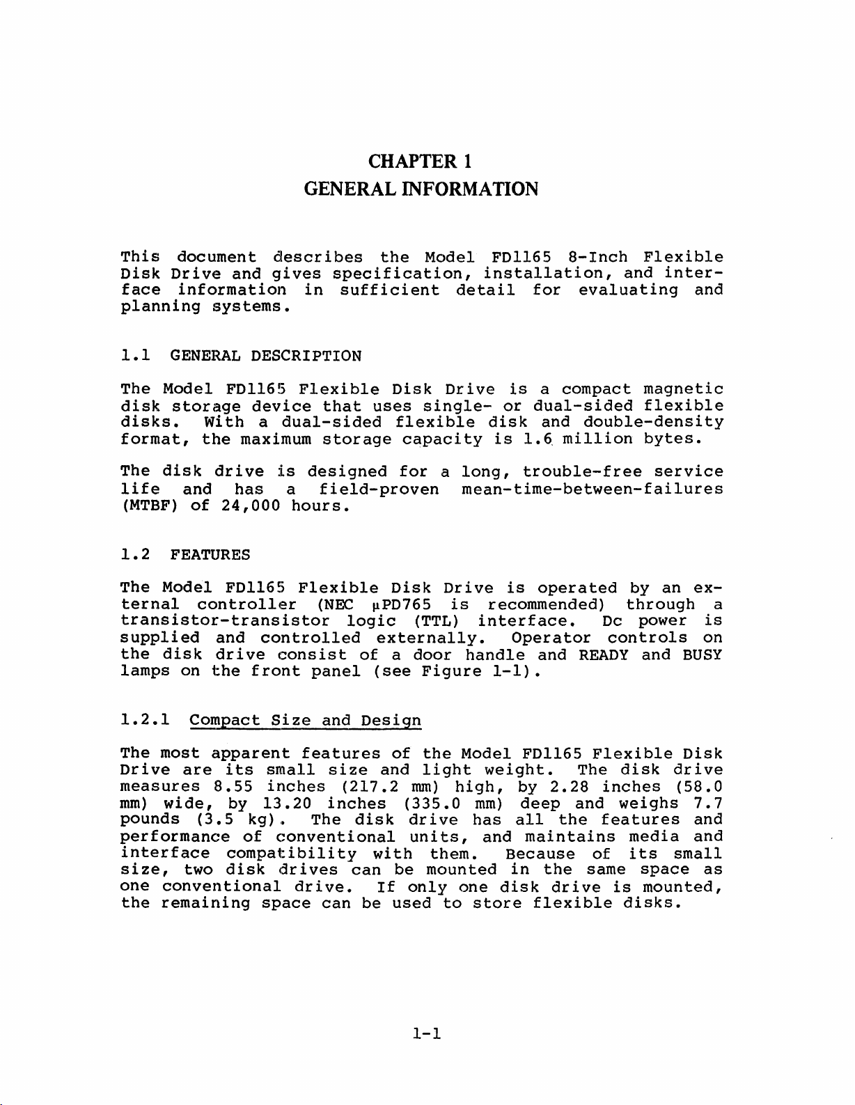
CHAPTER 1
GENERAL INFORMATION
This
Disk
face
planning
1.1
The
disk
disks.
format,
The
life
(MTBF)
1.2
The
ternal
document
Drive
information
systems.
GENERAL
Model
storage
wi
the
disk
drive
and
of
24,000
FEATURES
Model
controller
and
DESCRIPTION
FDl165
device
th
maximum
has
FDl165
transistor-transistor
supplied
the
disk
lamps
on
and
drive
the
front
describes
gives
in
Flexible
a
dual-sided
is
designed
a
field-proven
hours.
Flexible
(NEe
controlled
consist
panel
the
specification,
sufficient
Disk
that
uses
flexible
storage
capacity
for
Disk
~PD765
logic
externally.
of
a
(see
Model
single-
a
(TTL)
door
Figure
installation,
detail
Drive
long,
FDl165
is
or
disk
is
l.~
trouble-free
8-Inch
for
a
compact
evaluating
dual-sided
and
double-densi
million
and
mean-time-between-failures
Drive
is
is
operated
recommended)
interface.
Operator
handle
and
Dc
controls
READY
1-1).
Flexible
inter-
magnetic
flexible
bytes.
service
by
an
through
power
and
and
ty
ex-
a
is
on
BUSY
1.2.1
The
Drive
Compact
most
are
measures
mm)
pounds
wide,
(3.5
performance
interface
size,
one
the
two
conventional
remaining
Size
apparent
its
small
8.55
by
inches
13.20
kg)
,t
of
conventional
compatibility
disk
drives
space
and
features
size
inches
The
drive.
can
Design
(217.2
disk
with
can
If
be
of
and
be
used
the
light
mm)
(335.0
drive
units,
them.
mounted
only
1-1
Model
high,
one
to
weight.
mm)
has
and
Because
disk
store
FDl165
by
2.28
deep
all
maintains
in
the
drive
flexible
and
the
Flexible
The
inches
features
of
same
disk
weighs
media
its
space
is
mounted,
disks.
Disk
drive
(58.0
7.
and
and
small
7
as
Page 10
HEAD
LOAD
SOLENOID
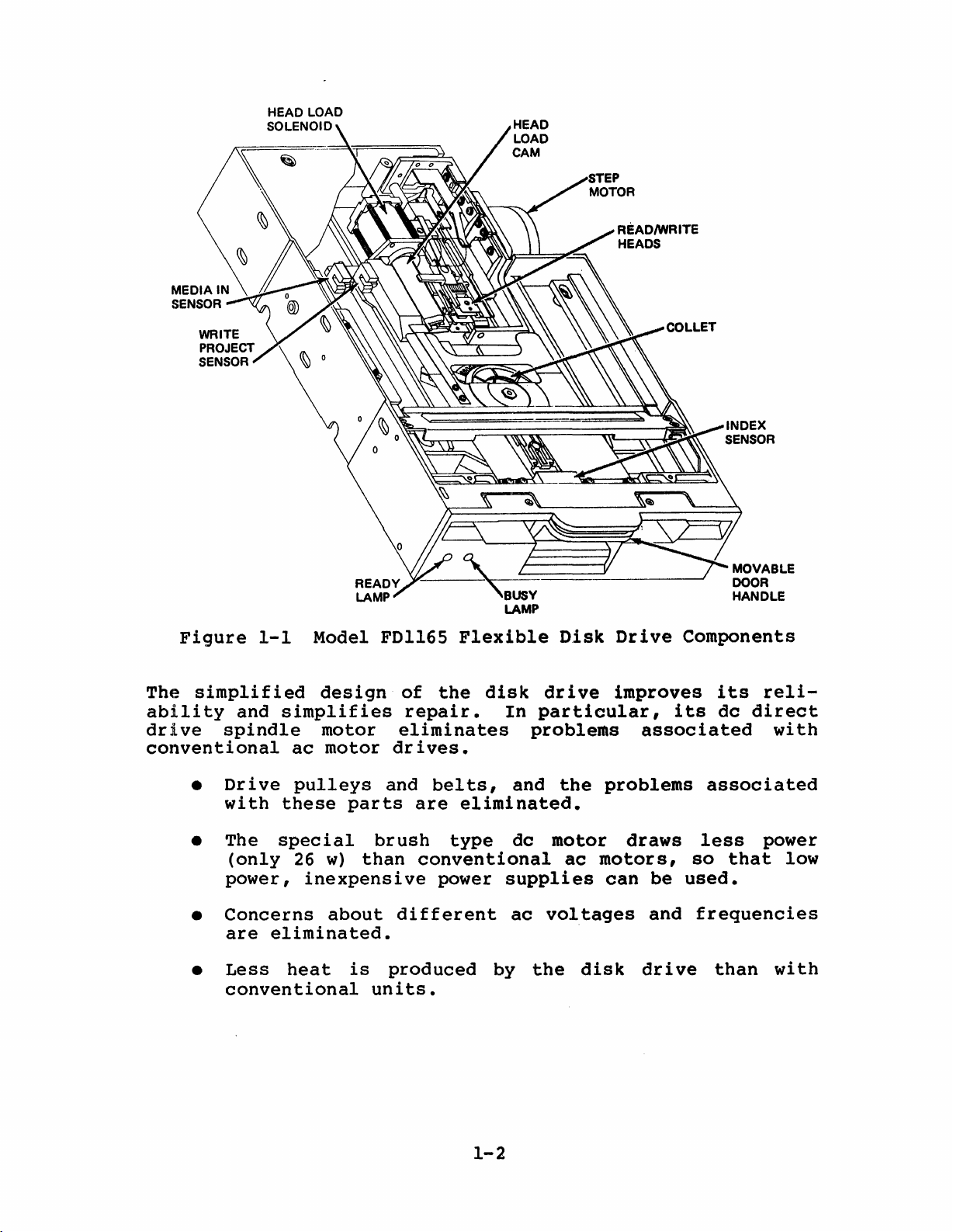
Figure
The
ability
drive
simplified
and
spindle
conventional
•
Drive
with
• The
(only
power,
•
Concerns
are
•
Less
conventional
1-1
Model FDl165
design
simplifies
motor
ac
motor
pulleys
these
special
26
w)
inexpensive
about
eliminated.
heat
parts
brush
than
is
units.
Y---~=====~~--_-I
LAMP
Flexible
of
the
repair.
eliminates
drives.
and
bel
are
type
conventional
power
different
produced
disk
In
ts,
and
eliminated.
dc
supplies
ac
by
D.isk
drive
particular,
problems
the
problems
motor
ac
motors,
voltages
the
disk
Drive
improves
associated
draws
can
be
and
drive
Components
its
reli-
its
dc
direct
associated
less
so
power
that
used.
frequencies
than
with
low
with
1-2
Page 11

1.2.2
~oadin9/Ejection,
Interlocks,
and
Sensors
Insert
door.
into
ing
same
s~indle,
mlnute
When
the
it
action
a
flexible
hole
in
rotating
(rpm).
ing:
a.
That
door
b.
Whether
loaded.
c.
Whether
d.
Whether
o:f
An
index
the
flexible
Before
the
if
the
front
sensor
you
flexible
the
door
of
operating
the
Sensors
the
slot
the
the
the
disk.
disk,
can
unload
panel
disk
disk
handle
the
flexible
position
drive
motor
the
flexible
is
closed.
a
single-
flexible
magnetic
generates
providing
must
be
is
into
flexible
in
the
disk
or
a
the
flexible
off.
being
the
latches
disk,
on
receives
disk
disk
is
dual-sided
disk
head
pulse
a
time
The
used
disk
closed,
centering
a
spindle
dc
at
drive
properly
has
a
is
located
once
reference.
disk,
door
by
the
drive
power,
360
detect
write
for
slot
host
and
a
collet
it
below.
it
revolutions
inserted
flexible
protect
on
the
each
the
BUSY
does
controller.
close
presses
and
By
moves
the
follow-
and
disk
00
rotation
lamp
not
the
clamp-
the
the
per
the
is
notch.
track
of
on
open
1.2.3
The
disk
dc
motor
minimizes
up-to-speed
The
the
flexible
spindle
springs
ible
disk
1.2.4
Data
using
heads
is
ceramic
are
mounted
heads
to
unloading
the
flexible
Dc
Direct
spindle
makes
the
power
time
disk
by
in
both
even
if
Read/Write
written
magnetic
located
on a
be
of
precision
shifted
a
flexible
disk
Drive
is
driven
drive
of
only
is
a
collet.
the
it
Heads
onto
on
from
surface.
Spindle
bel
required.
600
accurately
spindle
is
warped.
the
read/write
each
guide-bar
track
disk,
by
a
ts
and
ms.
Clamp
and
flexible
side
Motor
dc
The
collet
of
to
the
motor.
pulleys
motor
centered
pressure
disk
heads.
the
flexible
carriage,
track.
heads
This
unnecessary,
provides
and
is
to
protect
and
The
During
are
held
direct
clamped
relieved
the
read
read/write
disk
enabling
loading
away
drive
a
media
flex-
from
and
and
onto
by
it
are
the
and
from
1-3
Page 12
1.2.5
Microprocessor-Controlled
Head
positioning
The
motor,
This
step
head
the
riage
1.2.6
When
structiori,
faces.
head
step
positioning
linked
arrangement
motor
posi
is
tioning
motor
1/2
track
to
the
provides
controlled
reliabili
shaft
on
the
Microprocessor-Controlled
the
disk
Head
it
loading
drive
lowers
microprocessor-controlled
reducing
creasing
1.2.7
Two
LEOs
ready
damage
flexible
Display
on
and
busy
the
to
disk
LEOs
front
states
the
(access)
carriage
1.8
flexible
logic
the
force
flexible
operating
panel
of
fast
by a
ty.
degrees,
circuit
heads
is
special
provide
the
disk
mechanism
by a
and
tensioned
accurate
microprocessor,
Each
pulse
which
disk.
Head
Loading
receives
onto
the
controlled
cam
disk
life
governs
surface,
and
a
visual
drive.
consists
command
moves a
a
head
flexible
by a
data
display
of
steel
access.
increasing
rotates
head/car-
load
disk
solenoid.
head
loading,
thereby
integrity.
a
belt.
of
step
The
in-
sur-
A
in-
the
1.2.8
The
during
loss
1.2.9
Signal
by a
Door Lock
door
certain
or
physical
Interface
and
50-pin
grounds)
quency
1.2.10
The
Oscillator
Diagnostics
disk
cuitboard
conditions.
lock
data
are
drive
(PCB)
solenoid
drive
lines
edge
all
diagnostics
Solenoid
operations,
damage
interface
card
connector.
operated
(VFO)
plugs
makes
to
the
at
option
that
it
flexible
TTL
requires
consist
can
impossible
thereby
disk.
with
the
The 21
levels.
another
of
movable
be
used
to
preventing
host
active
The
to
establish
remove a
controller
lines
Variable
three
printed
disk
data
is
(plus
Fre-
lines.
cir-
test
1-4
Page 13
1.2.11
The
FDl165
as
well
function
your
particular
scription
Option
is
as
drive
plugs
of
Selection
equipped
door
allow
needs.
these
with
and
you
features.
See
signal
busy
to
lamp
tailor
Section
function
function
the
2.4.2.3
disk
selection
plugs.
drive
for
a
to
full
plugs,
These
suit
de-
1.2.12
The
optional
troller
reliability
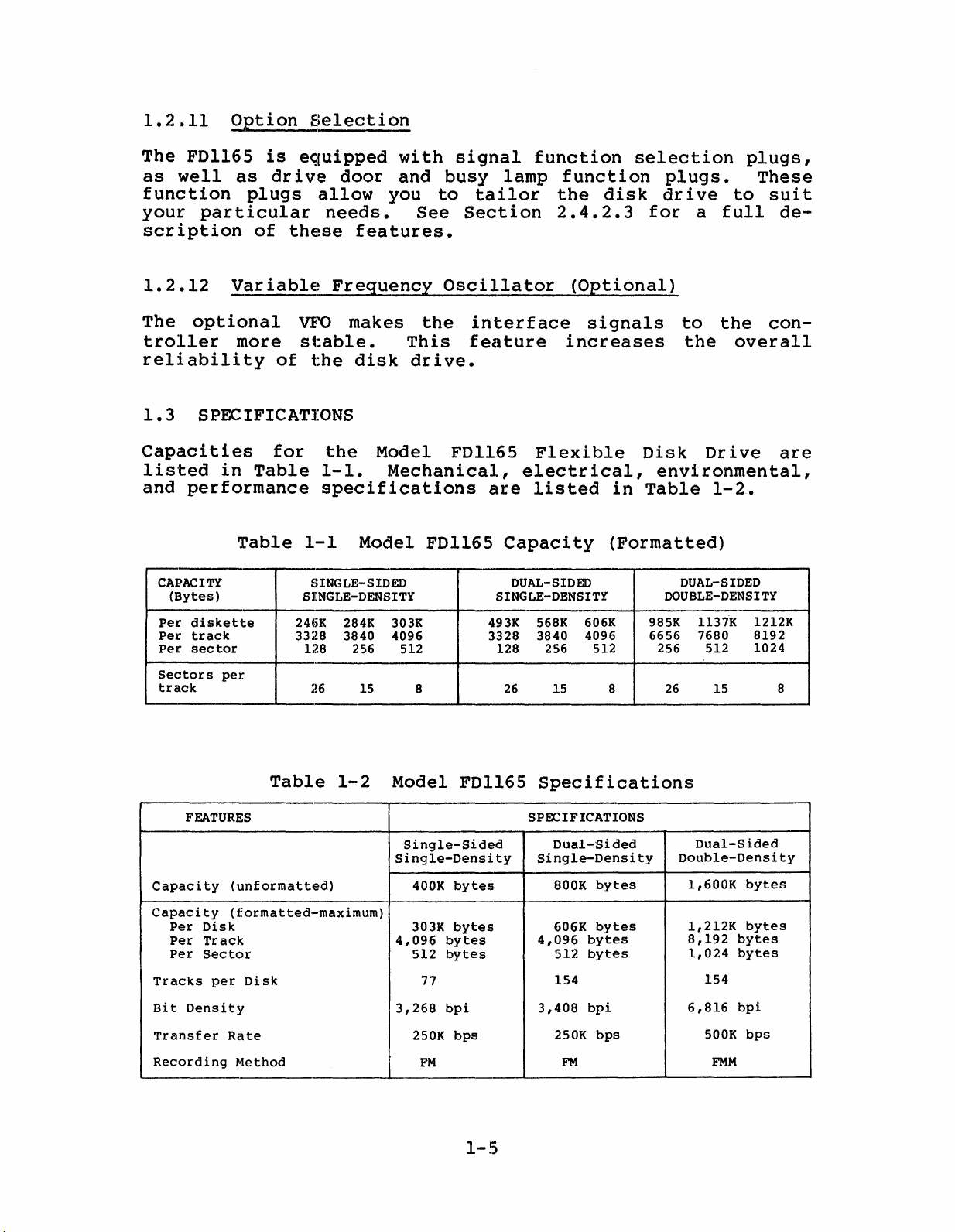
1.3
SPECIFICATIONS
Capacities
listed
and
performance
CAPACITY
(Bytes)
Per
diskette
Per
track
Per
sector
Sectors
track
Variable
more
in
Table
Table
per
of
for
Frequency
VFO
stable.
the
the
1-1.
makes
disk
Model
Mechanical,
Oscillator
the
This
drive.
FDl165
specifications
1-1
SINGLE-SIDED
SINGLE-DENSITY
24(;K
3328 3840 4096 3328
128 256 512 128
26
Model
284K
15
FD1l65
303K
8
interface
feature
Flexible
electrical,
are
listed
Capacity
DUAL-SIDED
SINGLE-DENSITY
493K 568K
3840 4096
26
(Optional)
signals
increases
606K 985K
256
15 8
Disk
environmental,
in
Table
(Formatted)
DOUBLE-DENSITY
512 256
6656 7680
26
to
the
the
overall
Drive
1-2.
DUAL-SIDED
1137K
512
15
con-
are
1212K
8192
1024
8
FEATURES
Capacity
Capacity
Per
Disk
Per
Track
Per
Sector
Tracks
Bit
Density
Transfer
Recording
Table
(unformatted)
(formatted-maximum)
per
Disk
Rate
Method
1-2
Model
Single-Sided
Single-Density
400K
303K
4,096
512
3,268
250K
FD1l65
bytes
bytes
bytes
bytes
77
bpi
bps
FM
1-5
Specifications
SPECIFICATIONS
Dual-Sided
Single-Density
bytes
800K
606K
512
154
250K
FM
bytes
bytes
bytes
bpi
bps
4,096
3,408
Dual-Sided
Double-Density
154
500K
FMM
bytes
bytes
bytes
bytes
bpi
bps
1,600K
1,212K
8,192
1,024
6,816
Page 14
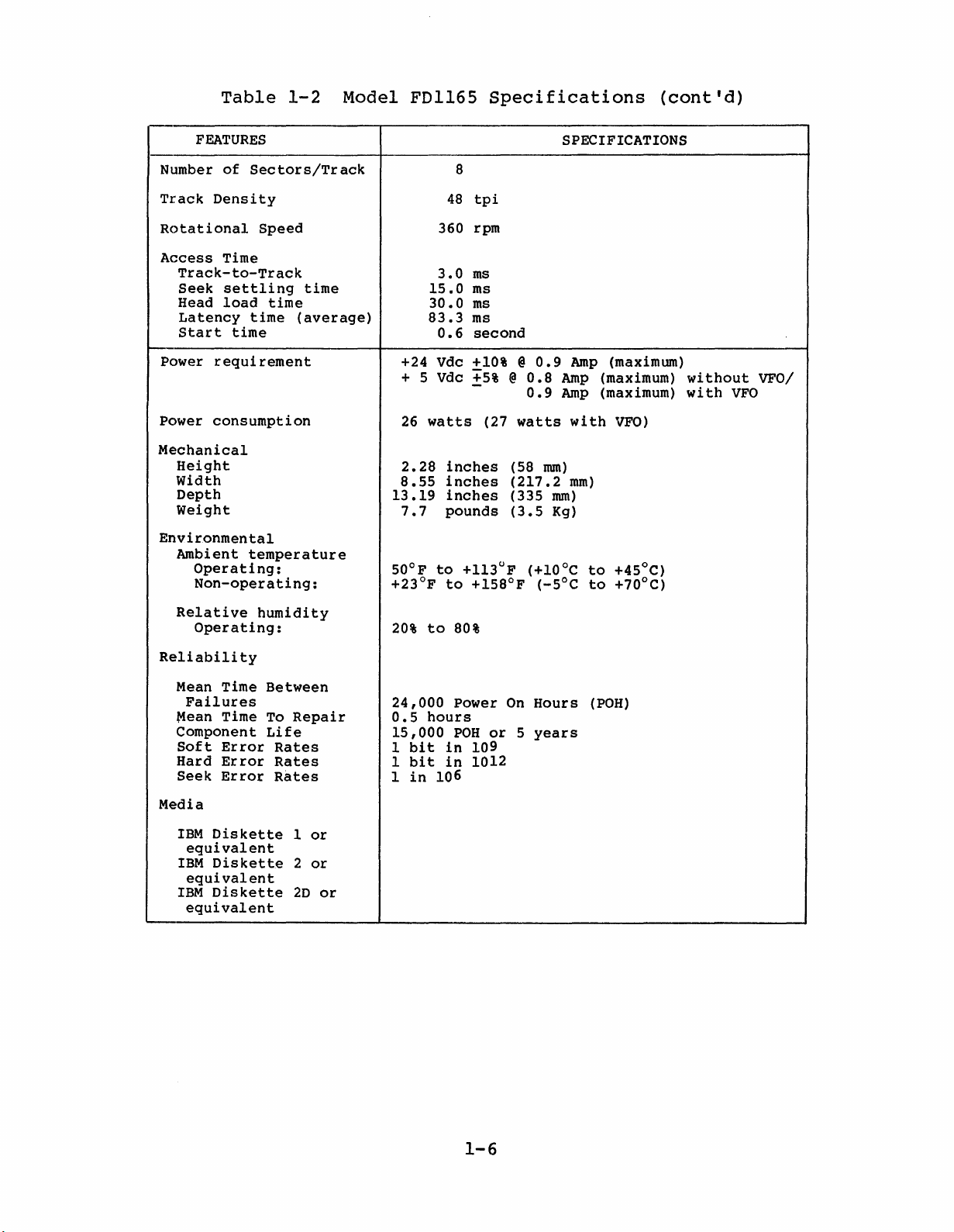
Table
1-2
Model
FDl165
Specifications
(cont'd)
FEATURES
of
Number
Track
Rotational
Access
Track-to-Track
Seek
Head
Latency
Start
Power
Power
Mechanical
Height
Width
Depth
Weight
Environmental
Ambient
Operating:
Non-operating:
Sectors/Track
Density
Time
settling
load
time
time
requirement
consumption
temperature
Speed
time
time
(average)
83.3
+24 Vdc
+ 5 Vdc
26
watts
2.28
8.55
13.19
7.7
50°F
+23°F
8
48
tpi
360 rpm
3.0
ms
15.0
ms
30.0
ms
ms
0.6
second
+10%@0.9
+5%@0.8
(27
inches
inches
inches
pounds
to
+113°F (+10oC
to
+158°F
0.9
watts
(58
mm)
(217.2
(335
(3.5
(-5°C
SPECIFICATIONS
Amp
(maximum)
Amp
(maximum)
Amp
(maximum)
with
VFO)
mm)
mm)
Kg)
to
+45°C)
to
+70oC)
without
with
VFO/
VFO
Relative
Operating:
Reliability
Mean Time
Failures
~ean
Time
Component
Soft
Error
Hard
Error
Seek
Error
Media
IBM
Diskette
equivalent
IBM
Diskette
equivalent
IBM
Diskette
equivalent
humidity
Between
To
Repair
Life
Rates
Rates
Rates
1
or
2
or
2D
or
20%
24,000
0.5
15,000
1
bit
1
bit
1
in
to
80%
Power
hours
POH
in
in
106
On
or5years
109
1012
Hours
(POH)
1-6
Page 15

CHAPTER 2
INSTALLATION
This
the
2.1
Before
spect
age,
until
carton
2.2
This
drive.
2.2.1
To
unpack
these
future
chapter
Model
PRELIMINARY INSPECTION
unpacking
the
notify
the
is
UNPACKING/REPACKING
section
Unpacking
steps.
use.
tells
FD1l65
shipping
the
carrier's
undamaged,
the
Flexible
carrier
describes
Procedure
disk
Save
the
carton
you
Model
representative
follow
drive,
all
how
to
inspect,
Disk
for
immediately.
PROCEDURE
how
shipping
Drive.
FDl165
any
the
unpacking
to
unpack
refer
Flexible
damage.
Do
inspects
to
Figure
materials
unpack,
Disk
If
not
procedure.
and
repack
there
open
2-1
for
and
it.
install
Drive,
is
the
the
and
possible
dam-
carton
If
disk
follow
in-
the
2.2.2
To
repackage
cedure
a.
b.
c.
d.
e.
Repacking
in
Remove
package.
Slide
round.
Open
Remove
Inspect
the
Section
a
the
the
the
the
disk
tape
styrofoam
styrofoam
plastic
disk
Procedure
drive
2.2.1.
band
case.
film
drive
for
from
case
cover
for
reshipment,
2-1
out
any
around
of
the
from
shipment
cardboard
the
reverse
the
disk
damage.
shipping
sur-
drive.
the
pro-
Page 16

PLASTIC
FILM
COVER
Figure
2-1
Unpacking
2-2
Diagram
Page 17

2.3
SYSTEM
REQU:IREMENTS
This
and
2.3.1
Install
environment
(lOoe
maximum
Aim.
Kcal/h
2.3.2
The
perpendicular
servicing.
unit
section
power
Operating
the
to
ambient
Typical
(23.3
Space
disk
weighs
describes
requirements.
Environment
dislt
with
45°C)
Kcallh
and
drive
Refer
7.7
and
stray
heat
shelf
pounds
drive
an
with
Weight
is
mounting.
to
the
environmental,
in
any
ambient
relative
magnetic
dissipation
VFO).
Data
designed
Figure
(3.5
2-2
Kg).
clean,
temperature
humidity
field
by
the
for
vertical,
Provide
for
overall
space
relatively
of
of
20%
is
specified
disk
space
dimensions.
and
dust-free
50°F
dri
horizontal,
for
to
80%.
ve
cabling
to
weight,
ll3°F
as
4000
is
22.3
The
or
and
The
Figure
2-2
Disk
2-3
Drive
Dimensions
Page 18

2.3.3
Power
Requirements
Because
dc
source
~
SPECIFICATION
Voltage
Normal
Starting
Ripple
Transient
time
2.4
INSTALLATION
Perform
2.4.1
the
Current
voltage
the
disk
must
Current
response
following
be
Preinstallation
drive
does
supplied
+24
+24
0.75
0.9
Not
400
200
POWER
V
10%
+
A
A
greater
mVpp
ms
PROCEDURE
procedures
Inspection
as
not
include
follows.
SUPPLY
than
to
0.8
(Wi
0.8
(Without
Not
70
install
a
+5
A
thout
A
greater
mVpp
power
V
POWER
+5 V +
VFO)
VFO)
the
than
disk
supply,
SUPPLY
5%
0.9
A
(With
0.9
A
(With
drive.
a
VFO)
VFO)
2.4.2
If
more
troller
series
the
the
cedure
disk
each
DX4).
tion
a.
Inspect
indications
are
b.
Remove
c.
Insert
door
collet
binding.
ible
d.
Press
disk
Drive
than
and
from
terminating
last
uni
are
drive
disk
drive
Instructions
2.4.2.2.
for
tightly
the
a
flexible
handle
assembly
Turn
disk
rotates
the
is
ejected.
Designation
one
the
signal
a common
resistors
t
in
provided
is
connected
by
damage,
of
mated.
dummy
to
door
disk
the
in
an
for
problems.
flexible
disk
latch
engages
the
spindle
freely.
handle
drive
interface
controller
from
series.
section
to
addressable
this
loose
Check
disk
through
posi
tion,
the
and
is
connected
connectors
port
all
Instr
2.4.2.1.
a
single
number
procedure
parts,
flexible
and
check
(daisy
disk
uctions
or
that
from
the
the
door,
and
check
that
to
dr
ive
If
controller,
(DXl,
are
provided
other
all
connectors
unit.
press
check
disk
that
the
the
same
are
chain),
PCBs
for
this
more
DX2, DX3,
obvious
that
wi
the
flexible
wired
remove
except
than
identify
in
the
the
thout
flex-
con-
in
pro-
one
or
Sec-
2-4
Page 19

2.4.2.1
Terminator
Resistors
All
move
Do
more
disk
(RNI
in
a
not
are
served
allel
line
remove
in
the
and
these
system.
remove
as
disk
in
series
RNI
circuit.
2.4.2.2
When
DRIVE
that
in
only
SELECTION
dr
ive
a
system
number and
ately
(see
selected.
drives
RN2)
installed
resistors
these
by a
shown by
drives
and
Drive
one
as
dfLsk
DXI.
(four
insert
Figure
are
shipped
as
when
resistors
single
are
(daisy
RN2
controller
(A)
in
connected
chain)
from
each
Identification
drive
shorting
When
maximum),
the
shorting
2-3).
shown
only
Figure
is
plug
two
The
with
in
a
when two
to
as
shown
disk
Selection
used
(see
or
more
assign
plug
unit
terminator
Figure
single
or
but
are
2-4.
the
However,
controller
in
drive
except
(OX)
in
a
Figure
disk
each
for
that
is
resistor
2-3.
disk
drive
more
connected
(B)
of
system,
2-3)
dr
ives
one
a
unit
supplied
Do
not
is
disk
in
if
on a
Figure
the
last
insert
to
identify
are
different
appropri-
with
arrays
re-
used
drives
par-
two
or
common
2-4,
one
the
used
OX
DXI
2.4.2.3
The
Option
following
FDl165 PCB.
tion
3
HEAD
When
a
select
Drive
plied
RADIAL
When
the
you
of
for
ted
plugs
an
explanation
LOAD
you
select
by a Head r..oad
plug
Select
with
READY
you
disk
select
drive
select
the
drive
selected.
and
PLUG
position
HL
PLUG
plug
Selection
section
See
pins
(HL)
plug
signal
1
selected.
plug
i.s
position
select
Figure
and a
of
position
signal
from
(RX)
position
gated
signal.
describes
2-3
the
2,
head
by
2,
for
the
configuration
signals.
1,
head
f rom
the
load
the
controller.
1,
the
the
the
The
Drive
Ready
unit
option
location
load
con
action
Ready
signal
is
selection
chart.
troller.
is
Select
supplied
of
action
initiated
The
signal
signal.
is
on
the
See
selec-
Chapter
is
initi-
When
unit
is
sent
independent
with
the
you
by a
sup-
from
When
RX
1
2-5
Page 20

rerGl
us
RN
1 l
~
RV1
211i:i11
I
1~~X3
22
••
; 4
(-R-N-2-'
:
.
1
SS
2'·
RD
....
'1
1I::::!J
T3
RV
1RX22
E:::]1!!3
2
HL
e:m::J
2
FR1
T2
2as11BU2
,,,•.i
DRI
E!!I211:!:!!)2Dl
PRI
~21r:::::::J2
T1
l!I!I
•.••
TP I I I I I
G89G
DH
TPI
I I I I I I I
7131019121118
RX,Hl,DR,
PR,
Dl,
BU,
US,RD,
PINS
(SOLDER TYPE)
DH,
PLUGS
OX
PLUG
1E:).
2.
POS1
POS1
----1
[ID
RV3
DX3 DX4
3
1
•
CJ
•
• •
4
2
BS,FR,
PLUGS
T2,T3
PLUGS
1 3
POS1
2.
T3·BT2
•
•
•
2
E31
T2
•
CJ
4
2E3
T3Ej,.
POS2
·1
T3
T2
1
•
~
2
DX2
3
•
•
•
4
DX1
1
3
•
~
2
•
2
POS2
1 •
POS2
2----·1
•
•
4
E:)2
Figure
Location
2-3
Terminator
and
Selection
Resistor
Plug
2-6
and
Selection
Configuration
on
Plug
PCB
Page 21

SIGNAL
CABLES
FLEXIBLE
DiSK
DRIVE
CONTROLLER
DC
CABLES
SIGNAL
(
CABLES
I
FLEXIBLE
DRIVE
DISK
DX1*
I
V
(A)
PARALLEL
1
FLEXIBLE
DISK
DRIVE
DX2*
CONFIGURATION
FOUR DRIVES
V
FLEXIBLE
DISK
(MAXIMUM)
A
DRIVE
DX3*
V
FLEXIBLE
DISK
DRIVE
DX4*
\
,
FLEXIBLE
DISK
DRIVE
CONTROLLER
DC
CABLES
*MOUNTTERMINATOR
Figure
RESISTOR
2-4
FLEXIBLE
DISK
I
ARRAYS
Cable
DRIVE
DX1
(B)
RN1
AND
Connections
to
Controller
FLEXIBLE
DISK
DX2
SERIAL
RN2
FLEXIBLE
DRIVE
CONFIGURATION
DISK
from
DRIVE
DX3
Disk
FLEXIBLE
DISK
Drives
DRIVE
DX4
2-7
Page 22

SIDE SELECT
you
When
the
controller
position
mines
unit
the
selected.
uni
select
2,
disk
selects
t
PLUG
the
side.
side
selects
(SS)
plug
determines
Direction
If
position
the
O.
side
Direction
If
the
2.
1,
disk
Signal
Direction
The
the
side.
from
uni
Side
Signal
t
is
Select
When
the
level
Signal
supplied
signal
you
controller
select
is
level
high,
wi
is
th
from
plug
deter-
the
low,
SS 1
WRITE
When
Write
ing
you
Protect
if
is
FILE
When
function.
File
selected.
DOOR
The
different
occurs
from
door
function.
if
select
the
supplied
UNSAFE
you
LOCK
FDl165
the
PROTECT
you
Unsafe
lock
select
Protect
the
signal
flexible
select
PLUGS
combinations,
(see
disk
PLUG
signal
flexible
plug
to
with
PLUG
plug
When
three
Table
condition
you
function.
(DR, DL,
drive
(PR)
plug
position
the
disk
PR
1
(FR)
position
select
door
2-1).
when
consists
position
to
the
disk
controller
has
selected.
The
DH)
lock
determine
The
a
controller
has
2,
the
a wr i
1,
plug
function
flexible
door
1,
a wr i
te
you
position
unit
lock
of
the
te
disk
but
protect
is
when
a
lock
disk
and
protect
drive
allows
disable
supplied
plugs,
a
door
disk
condition
function
prevents
recording,
notch.
the
2,
you
which
lock
cannot
drive
notch.
sends
exists.
sends
a
The
File
enable
with
you
condition
be
or
record-
When
Write
even
uni
Unsafe
the
FR
use
removed
a
in
The
hold
a
t
2
•
DR
Plug
When
locks
Head
position
status,
Load
DR
1
you
select
when
Load
2,
that
status
selected.
Ready
status
the
are
is,
plug
status,
are
door
when
present.
position
present.
locks
Drive
2-8
1,
Drive
When
independently
Select
The
unit
the
Select
is
disk
you
status
supplied
drive
status,
select
of
and
door
and
plug
Ready
Head
with
Page 23

•
•
DL
Plug
For
and
DL
status
exist
DL
1,
door
When
pends
with
DH
Plug
a
In
plug
plug
you
DL
door
Use
determines
depends
as
long
is
lock
select
on
the
1
selected.
lock
signals
as
present.
hold
In
hold
on.
the
depends
plug
Use
condition
must
be
which
The
door
signal
When
position
signal.
signal
you
on
to
present
lock
that
select
the
Drive
2,
The
occur,
ini
the
hold
is
selected
door
uni
Drive
tially.
door
plug
Select
lock
t
lock
status
position
hold
is·
suppli
Select
The
hold
will
by
the
signal.
de-
ed
NO.
1
2
This
you
status.
the
selected.
PLUG
ID
DR
DL
DH
DR
DL
DH
plug
select
controls
plug
When
hold
Table
status.
2-1
PLUG,
POSITION
1 1
1
(hold
1
disable)
1 1
1
(hold
1
enable)
the
position
you
select
The
Door Lock
IN
USE
POSITION
door
uni
PLUG
1,
plug
t
Plug
Door
Drive
Load
Door
Door
Drive
Load
Door
and
lock
you
hold
disable
position
is
supplied
Combinations
EXPLANATION
lock
Select
or
lock
and
In
Use
lock
Select
lock
In
Use
status.
2,
you
wi
= Ready
and Head
=
Drive
=
Ready
and
=
Drive
the
th
and
Select
and
Head
Select
When
hold
enable
DH
1
3
DR
DL
DH
4
DR
DL
DH
1 2
1
1 Load
2
2
2
(disable)
2
2-9
Door
Drive
Door
lock
Select
lock
= Ready
=
and Head Load
and
Drive
and
Head
Select
Page 24

IN
USE
You
cannot
the
connections.
connect
signal
is
supplied
PINS
(US)
select
pin
1
when you
with
In
You
to
the
connect
USI
Use by
the
enable
center
pin
connected.
2
plug
the
pin.
to
method:
In
You
the
Use
disable
center
you
signal
pin.
must
when you
the
In
The
solder
Use
unit
READ
You
must
select
signal
the
Standardized
connect
RDI
connected.
BUSY
The
busy
busy
BS
2
• Busy
• Busy
DATA
PINS
solder
them by
when you
pin
LAMP
PLUGS
lamp
lamp
will
selected.
To
have
present,
To
have
is
present,
2
to
plugs
Lamp
Lamp
(RD)
the
the
connect
Read
the
(BU,
be
on.
on
the
busy
select
on
the
busy
select
connections
plug
method.
pin
Data
center
BS)
determine
The
During
Head Load
lamp on when a Head Load
BU2and
During
Drive
lamp
BU2and
1
to
signal
pin.
the
unit
BS
on when a
at
the
You
the
center
(for
The
unit
conditions
is
supplied
2.
Select
BS
1.
RD
enable
VFO
Drive
pins:
the
pin.
option)
is
supplied
under
with
Select
you
cannot
Read
You
enable
when you
which
BU
2
signal
signal
Data
with
the
and
is
• Busy
To
present,
2.4.2.4
Diagnostic
T2
and
T3.
the
center
AUTO
The
To
TAP
auto
select
a.
b.
Lamp
have
Diagnostic
tests
Normally
pin).
TEST
tap
the
auto
Turn
off
Connect
on
During
the
busy
Select
Plugs
are
test
consists
tap
the
diagnostic
In
lamp
BU1and
(T2,
performed
these
pins
test:
power.
pins
Use
on when
remove
T3)
by
of
T2
2-10
are
a
use
head
to
an
the
of
the
open
load/unload
the
center
In
Use
BS
plug.
diagnostic
(not
connected
signal
pin.
is
pins
to
action.
Page 25

c.
d.
Select
Turn
HL2and
on
the
connect
power
and
HL2
the
to
auto
ground.
tap
test
starts.
AUTO
The
to
track
the
AUTO
This
To
select
SEEK
auto
auto
a.
b.
c.
SEEK
test
a.
b.
c.
d.
TEST
seek
76
with
seek
Turn
off
Connect
Turn
on
AND
performs
the
Turn
off
Connect
Select
Turn
starts.
test
test:
the
diagnostic
the
TJ~P
auto
the
diagnostic
HL2
on
the
consists
the
power
TEST
both
seek
and
read/write
power.
and
auto
and
power.
connect
power
pin
tap
pins
and
of
the
seek
HL2
T3
test:
T2
the
a
seek
heads
to
auto
and
to
the
seek
and
T3
ground.
auto
action
unloaded.
center
test
auto
to
tap
the
seek
from
To
pin.
starts.
functions.
center
and
track
tap
0
select
pin.
test
HEAD
To
UNLOAD
delay
ground.
nored
pin
is
2.4G2.5
The
TP
2-2
G
facturing
the
With
when
open.
Test
numbers
Test
only.
DELAY
head
Tl
they
Pins
pins
(Tl)
shorted,
occur
and
not
unload
less
(TP)
the
listed
action
head
than
signals
load/unload
250
availale
in
'the
2-11
250
ms
table
ms,
apart.
are
are
short
pin
commands
Normally
listed
used
in
in
Tl
are
to
ig-
this
Table
manu-
Page 26

PIN
NUMBER
Table
2-2
Test
Pins
and
Signals
SIGNAL
2.4.2.6
There
the
write
tory
mines
justed
TP
TP8,
TP
TP
TP
TP
are
and
the
at
7
9
10
11
12
13
Trimpots
three
current.
should
speed
166.6
trimpots
These
never
of
the
±
0.5
Index
Analog
head
adjust
Index
Write
Track
Media
on
trimpots
be
adjusted
spindle
ms.
signal
signal
output.
CE,
signal
Protect
0
signal
detect
the
for
(differential)
Use
Azimuth,
for
signal
sensor
PCB.
are
in
motor.
dual-sided
to
check
or
Index
Single-sided
output
RVI
and
adjusted
the
field.
This
media
or
RV2
at
RV3
trimpot
of
burst.
media
determine
the
fac-
deter-
is
ad-
2.4.3
The
Mounting
disk
drive
peI'pendicular.
Figures
for
disk
air
cooling
sured,
Interface
For
to
Chapter
2-5,
adequate
drive
you may
cabling
further
air
is
is
details
3.
and
Wiring
can
be
Recommended
2-6,
and
flow
installed
necessary.
need
a
details
on
mounted
2-7.
are
in
If
forced
are
logic
vertically
mounting
Recommended
shown
the
in
standard
smooth
air
cooling
shown
in
lines
methods
Figure
air
Figures
in
the
or
horizontally
space
2-8.
manner,
flow
cannot
system.
connector,
are
shown
requirements
When
no
forced
be
2-9
and
2-10.
refer
and
in
the
en-
2-12
Page 27

,,--,
I \
KNOB
./'
/1/1/1//1111/1
\ J
..-'
" /
Figure
COLLET
SPINDLE MOTOR
Figure
2-5
ASSEMBLY
2-6
\ STEP MOTOR
Vertical
Horizontal
I I I
Installation
Installation
SPINDLE MOTOR
STEP
MOTOR
I
Figure
2-7
KNOB
" "
I I
\ /
'-
11111111/1/
Perpendicular
2-13
-
Installation
Page 28

AIR
FLOW
COUPLED BRACKET
20mm
20mm
/
~/
(A)
/
One
Disk
Drive
EXTERNAL
WALL
NOTE:
Figure
lotmmJ-~
AIR
FLOW SHOWN BY SOLID LINES
AIR
FLOW SHOWN BY BROKEN LINES
BY HOLES IN THE COUPLED BRACKET.
2-8
Air
+----.........--+--+-
(B)
Flow
Two
or
PASSES
Requirements
Four
PASSES
Disk
AROUND DISK DRIVES.
THROUGH DISK DRIVES
for
2-14
Drives
Natural
Air
Cooling
Page 29

CONTROLLER
SI<3NAL NAME
LOW
CURRENT
UNSAFE RESET
FILE
UNSAFE
TWO
SIDED
DISK CHANGE
SIDE SELECT
IN
USE
HEAD LOAD
INDEX
READY
VFO
SYNC·
DRIVE SELECT 1
DfUVE SELECT 2
DRIVE
SELECT 3
DfUVESELECT 4
DIRECTION SELECT
STEP
WRITE
DATA
WFUTE
GATE
TRACK
WRITE PROTECT
READ
MFM*
WINDOW*
00
DATA
10
12
14
16
18
2·0
22
24
26
28
30
32
34
36
38
40
42
44
46
48
50
PIN
NO.
2
4
6
8
DISK
DRIVE
SIGNAL
CONN.
SIGNAL
DC
GROUND
DC+5V
GROUND
FG
*SIGNALS USED
Figure
2-9
NAME
+24 V
ONLY
WHEN VFO OPTIONISINSTALLED.
Interface
and
Cables
Controller
Between
Disk
PIN
NO.
1
2
3
4
5
6
7
Drive
POWER
CONN.
2-15
Page 30

SIGNAL
CONNECTOR
Figure
2.4.4
After
all
connections,
a.
b.
POWER CONNECTOR
2-10
Power
Interface
On
you mount
Install
Check
motor
speed.
Use
to
whatever
exercise
operations,
Testing
the
then
a
for
starts
Connectors
disk
test
test
flexible
drive
using
abnormalities
and
brings
diagnostic
the
and
disk
repeated
POWER RECEPTACLE
Physical
and
select
this
test
drive
disk
and
the
through
general
and
note
disk
programs
head-positioning
Location
the
wiring,
procedure.
apply
that
spindle
write
are
Diagram
verify
dc
power.
the
drive
up
available
and
scans.
to
read
2-16
Page 31

CHAPTER 3
This
chapter
between
3.1
The
DATA
data
50-contact
disk
drive.
numbered
PCB,
and
component
signal
assignments
3-2.
describes
the
FDl165
INTERFACE
and
edge
The
contacts
the
odd-numbered
side
INTERF,ACE
Flexible
CONNECTOR
control
card
pins
of
connector
are
are
the
for
the
data
Disk
line
numbered 1
located
contacts
PCB,
this
INFORMA
and
control
Drive
DATA
interface
located
through
on
the
are
as
shown
connector
nON
interface
and
its
connects
on
the
50.
component
located
in
Figure
are
shown
controller.
through
PCB
side
on
The
of
even-
of
the
3-1.
in
Figure
lines
a
the
the
non.
The
3.2
All
fined
2 4 6 8 48
'""""""-,,------tll--------
3 5 7
Figure
SIGNAr~
data
as
and
follows.
True
False
LEVELS
control
=
Logic
-
Logic
3-1
LOGIC
Data
0
1
(low
(high
and
Control
interface
level)
level)
lines
..............
47
Interface
are
SIGNAL
o
to
+2.5
~-'
50_
49_
Connector
at
TTL
+0.4
to
CONTACT NUMBER
THE COMPONENTSIDE
CONTACT NUMBER
THE NON COMPONENT
SIDE
levels,
LEVEL
Vdc
+5.25
Vdc
ON
ON
de-
3-1
Page 32

NON COMPONENT
SIDE OF
PCB
COMPON
OF
PCB
ENTSIDE
GROUNDS
1~
3~
5~
7~
9~
11~
13~
15~
17~
19~
21~
23~
25~
27~
29~
31~
33~
35~
37~
39~
41
~
43~
45~.
47~
49~
CONTACT
NUMBERS
~
~
~
~
~
~
~
~
~
~
I§§§
~24
§§§J
§§§J
~30
~32
~34
~36
~38
~40
I§§§
~44
§§§J46
~48
~·50
2
4
6
8
10
12
14
16
18
20
22
26
28
42
SIGNAL
LOW CURRENT
UNSAFE RESET
FILE
(UNUSED)
TWO-SIDED
DISK CHANGE
SIDE SELECT
IN
HEAD
INDEX
READY
VFOSYNC
DRIVE
DRIVE
DRIVE
DRIVE
DIRECTION SELECT
STEP
WRITE
WRITE GATE
TRACK
WRITE PROTECT
READ
MFM
WINDOW **
NAME
UNSAFE *
*
USE
LOAD
*
*
**
SELECT 1 *
SELECT 2 *
SELECT 3 *
SELECT 4 *
DATA
00
DATA
**
Figure
Each
to
driver
the
provides
Each
receiver
controller
resistor.
trigger
shown
in
*SIGNALS
** SIGNALS USED
3-2
ENABLEDBYPLUGS
Signal
circuit
controlle~
is
a maximum
circuit
is
an
LSI
Lines
gate.
Figure
receiving
The recommended
3-3.
ONLY
WHEN VFO OPTIONISINSTALLED
Edge
delivering
an
sink
Cord
open
current
Connector
a
co~lector
of
receiving
gate
circui
at
t,
high
driver/receiver
3-2
signal
40
a
drive
terminated
Contact
from
type
rnA
at
speeds
the
of
SN7438,
the
signal
at
use
Assignments
disk
drive
which
low
level.
from
a ISO-ohm
a
Schmitt
circuits
the
are
Page 33

CONTROLLER
7438OREQUIVALENT
DRIVER
CIRCUIT
~
+5
V
MAXIMUM
TWISTED PAIR 6 m
FLAT
RIBBON 3 m
HIGH
II
CABLE LENGTH
SPEED
LINE
DISK DRIVE
+5V
+5V
I 7438
LSI
OR
EQUIVALENT
~
RECEIVER
CIRCUIT CIRCUIT
3.3
Descriptions
low.
3.3.1
These
disk
fective
To
the
to
shorting
INPUT
Drive
lines
drive
when
designate
desired
designate
plug
150 A
~
Figur(:~
SIGNAL
of
Select
select
is
its
terminal
the
selected
drive
each
a
specific
into
3-3
FUNCTIONS
disk
the
~\
Driver
disk
1
to
one
select
DXl
DXl
~ft~'thl
and
Receiver
drive
4 (DXl
to
four
and
drive,
to
disk
terminals
its
line
DX4
drive
input
to
DX4)
disk
input/output
goes
insert
on
signal
drives
a
the
as
(see
-'-I
Circuits
low.
shorting
PCB.
number
Figure
/I.
DRIVER
functions
in
a
lines
For
1,
2-3).
system.
are
plug
example,
insert
fol-
A
ef-
into
the
3.3.2
If
the
the
Head Load
disk
disk
drive
drive
to
(HDL)
is
ready,
initiate
a low
head
3-3
level
loading.
on
this
line
directs
Page 34

3.3.3
Step
(STP)
This
to
line.
going)
track.
shown
3.3.4
If
ternal
toward
trailing
line
track
in
STP----~U
DIR
carr
in
the
The
edge
heads
of
The
Figure
-1W~T-1
Direction
is
at
track.
the
internal
edge
ies
direction
each
repeti
3-4.
Figure
the
If
of
a
start
tion
Select
high
it
track.
the
pulse
pulse.
3-4
level,
is
STP
that
designated
to
move
One
rate
Step
(DIR)
at
the
The
signal.
and
u
the
moves
at
pulse
width
Signal
head
low
signal
by
the
level,
occurs
the
heads
the
leading
moves
of
T::
5 ms
W::
1
Il~.
Timing
moves
from
DIRECTION SELECT
the
this
heads
pulse
track
(positive
one
are
u
(MIN)
TO 2.5 ms
toward
the
Ips
the
head
before
ex-
moves
the
3.3.5
If
SSL
side).
nal
SSL
that
3.3.6
If
If
Data
signal
off,
tion
nals
chart
3.3.7
This
written
modified
side
this
the
is
the
can
Side
is
If
it
occurs
0
write
line
line
erased
level
SIDE SELECT
be
are
line
is
shown
Write
on
frequency
both
(WDT)
the
Select
high,
is
100
is
used
Gate
is
is
high,
from
goes
enabled
at
in
Data
flexible
(SSL)
it
low,
ps
in
(WGT)
low,
data
the
high.
only
the
Figure
(WDT)
supplies
modulated
selects
it
before
the
data
signal
high
disk
flexible
selects
the
single-sided
is
written
is
read
flexible
The
HEAD
can
when
3-5.
the
level.
the
in
(MFM)
side
READ/WRITE
from
disk
LOAD
be
WRITE
disk
frequency
1
to
the
changed,
The
drive
format
disk
(lower
disk.
the
for
signal
GATE
WRITE
modulated
(see
side
side).
operation.
flexible
flexible
560
with
ps
can
and
and
GATE
Figure
0
after
be
STEP
ERASE
data
(upper
disk.
turned
opera-
timing
(FM)
3-6).
Sig-
Note
disk.
sig-
to
the
be
or
3-4
Page 35

WGT
,
I
ERA
(INS
SE
SIGNAL.
IDE FDD)
T
1
T
2
~
NOTE: THE
WDT
(FM)
,
HEAD
SIGNAL
BE
ENABLED
Figure
LOAD
3-5
SIGNAL
IN THIS
TO1ma
INTERVAL.
Write
CANNOTBECHANGED,
T - 2 ps
W.. 0.15
CANNOTBETURNED
AND
THE
STEP OPERATION
Gate
(2T • 4
Signal
p.s
:t 12
ns)
:...--T
OFF,
--+
3
THE
SIDE SELECT
CANNOT
Timing
T1-100
T2-195ps
T3-
560/o&s
/O&S
(M
(M
AX)
AX)
WDT
(MFM) I
_---J
Figure
W
I-
T =2ps
W .. 0.15psTO
3-6
1
ps
Write
Data
3-5
(2T - 4 ps ± 12
Signal
ns)
Timing
Page 36

3.3.8
Current
Changeover
(LWC)
During
pensate
During
teristic
should
ternal
3.3.9
A low
Reset
FLR
3.3.10
A low on
lock
3.4
A
condition.
OUTPUT
description
lows.
WRITE
for
READ
of
be
high
tracks
resets
In
Use
this
operations,
high-densi
operations,
a
preamplifier.
in
external
(43
to
(FLR)
FILE
line
SIGNAL
of
FUNCTIONS
the
LWC
ty
LWC
76).
UNSAFE
instructs
functions
controls
records
changes
For
tracks
status.
the
WRITE
in
the
the
READ/WRITE
(00
to
disk
of
the
drive
output
current
internal
frequency
operation,
42) and low
to
hold
signals
to
comtracks.
charac-
LWC
in
in-
a
door
fol-
3.4.1
This
line
flexible
shown
3.4.2
When
TKC
3.4.3
This
line
and low
serted,
Index
(lOX)
(lOX)
disk
in
Figure
Track
is
00
low,
Dual-Sided
(TSD)
if
it
TSD
remains
signals
once
3-7.
(TKC)
the
(TSD)
is
is
lOX
the
every
head
high
rotation.
is
if
dual-sided.
high.
T - 166.7:l: 3.3
W-1
the
start
on
flexible
TO 3.5
the
If
ma
no
ms
point
The
zero
flexible
of
resulting
track.
disk
a
track
on
pulse
is
single~sided
disk
is
the
is
in-
Figure
3-7
Index
3-6
Signal
Timing
Page 37

3.4.4
Ready
(ROY)
When
following
3.4.5
A
operations.
It
•
• The
•
•
low
is
•
ROY
Dc
closed.
Rotational
more
detected
Only
is
File
FUS
active
WGT.WDT
is
low,
conditions.
power
flexible
than
side
single-sided.
Unsafe
indicates
This
for
is
the
any
The
within
active.
the
speed
70%
0
line
disk
supplied.
disk
of
of
speed
IDX
signal
has
(FUS)
an
been
alarm
is
of
the
WRITE
18
dri
ve
has
reset
been
the
and
four
selected
condition
following
DATA
s
is
flexible
the
or
to
high
signal
after
ready,
inserted
disk
disk
more
if
and
conditions.
WRITE
drive
times.
the
it
by
does
indicating
and
has
flexible
inhibits
the
FUR
not
GATE
the
reached
logic
signal.
appear
becomes
the
door
has
disk
write
•
•
•
3.4.6
This
the
signal
option
mitted
inserted
wavetrain
line
flexible
HDr:.WGT
ROY.WGT
WGT
.STP - The
Read
or
(see
only
the
on
is
Data
(RDT)
disk
Section
when
the
shown
-
The
LOAD
- The
is
the
STANDARDIZED
1
WRITE
is
WRITE
not.
STEP
WRITE
(ROT)
conveys
drive.
3.5.3).
the
RD
side.
in
Figure
not.
shorting
GATE
GATE
signal
GATE
signal-conditioned
This
READ
A
typical
3-8.
The
signal
signal
is
signal
line
DATA
READ
active
is
transmits
signal
DATA
plug
RDT
is
active
active
is
the
at
active.
data
the
used
signal
(See
conditioned
Figure
but
read
READ
for
is
but
same
the
2-3)
digital
HEAD
READY
time
from
DATA
VFO
trans-
is
3-7
Page 38

RDT
(FM)
w=200 ± 50
ROT
(MFM)
T =2
IJS
ns
T 1.5T 1.5T
~+
Figure
3-8
-+-
Read
Data
+-
Signal
Timing
w...-.-..
2T
~
3.4.7
This
WRITE
notch
3.4.8
This
flexible
selected.
line
signal
Write
is
PROTECT
prevents
Disk
Change
disk
The
Protect
high
notch
writing.
goes
has
time
DOOR
DRIVE
SELECT
(PRT)
when
and low
(DCG)
low
been
CLOSE
<P
to
changed
relationships
1~-O-PE-N--I_c_L_OS_E
the
flexible
if
signal
since
I
DISK
the
the
are
CHANGE
disk
disk
controller
the
disk
shown
does
has
in
a
drive
Figure
_
not
notch.
that
was
have
last
3-9.
a
A
the
DISK
CHANGE
Figure
<P
3-9
Disk
u
Change
3-8
Signal
Timing
Page 39

3.5
VFO
INTERFACE
SIGNAL
FUNCTIONS
The
scribed
3.5.1
This
The
3.5.2
This
VFO
synchronized.
3.5.3
This
ized
liably
READ
3-10.
is
functions
in
Modified
line
line
VFO
controller
circuit.
Standardized
line
by
the
read.
DATA
(Timing
passed
is
conveys
of
the
the
following
Frequency
is
low when
high
Synchronization
VFO
SIGNAL
until
when
signal
The
The
line
Read
STANDARDIZED
circuit
time
AND
becomes
the
VFO
optional
sections.
Modulated
MFM
FM
specifies
is
relationship
THE
irregular
data
data
(BYC)
low
Data
to
make
WINDOW
is
re-synchronized.)
VFO
is
to
only
(SRD)
READ
it
interface
Mode
is
to
be
the
when
DATA,
more
between
signal
once
(MFM)
be
read
read
operating
the
or
read
which
easily
the
fs
data
shown
signal
or
written.
mode
data
is
and
STANDARDIZED
splice
are
written.
of
is
being
synchron-
more
in
Figure
point
de-
the
re-
3.5.4
This
output.
STANDARDIZED
READ
Window
signal
Phase
DATA
(ROT)
WINDOW (WID)
Figure
(WID)
distinguishes
matching
READ
DATA
----aU
~X
~
3--10 Read
between
of
the
signal
--1
O.5T1
~-4-
Data
is
r-
and
125os.10%
O.5T
clock
WINDOW
done
X'-
1-
Window
pulses
signal
by
the
u
T2·2ps± 10%
T
-1
PI ± 10%
1
Signal
and
with
controller.
..",X'-
(FM)
(MFM)
Timing
data
the
__
3-9
Page 40

3.6
A
description
follows.
INTERFACE TIMING
of
the
interface
timing
of
the
disk
drive
3.6.1
Valid
700
3.6.2
Valid
500
DX3,
3.6.3
The
signal
3-11.
Power
input/output
ms
after
Drive
input/output
ns
after
or
DX4)
Step
required
and
On
Sequence
signals
the
Select
the
goes
and
time
the
door
Track
TRACK
slot
signals
appropriate
low.
00
relationship
00
STP----U
TRO
----------+---
are
is
are
output
processed
closed.
processed
dr
ive
between
signal
u
select
.....
the
is
by
by
the
the
line
STEP
shown
disk
disk
(DXl,
controller
in
drive
drive
Figure
DX2,
Figure
3.6.4
The
DIRECTION SELECT
Access
required
time
3-11
relationship
controller
Step
and
signals
3-10
Track
among
T
-.I
00
WRITE
is
T
Signal
shown
·2.5ms(MAX)
Timing
GATE"
in
Figure
STEP,
and
3-12.
Page 41

WRITE GATE (WGT)
---I!:~I
STEP (STP)
DIRECTION SEL.ECT
DIR)
NOTE: WHEN THE DIRECTION SELECT (DIR)
3.6.5
The
a
WRITE
HEADLOAD(HDU~~~
Write
required
operation
STEP PULSE
time
I---
STEP (STP)
l..nJljr-------------------
--------
INTERVAL
Figure
relationship
is
3-12
shown
50ms(MINI---.j
__
~
rsms+18mS(MIN)
MUSTBEMORE
Access
in
Figure
of
controller
SIGNAL
THAN
Timing
3-13.
......
CHANGES, THE
18 ms.
signals
during
_
SIDE SELECT (SSU
WR
ITE GATE
WRITE
DATA
(WGn
(WDT)
_I
'--{--,---------.J-*-:O~s
~'
'---I
--..I
-----------~lJl.Jlr
Figure
3-13
\--18
......
.---I00"'(MINI-~
ms
(MINI
'~N)
,--
r--
write
4'"(MAX)
Timing
- -
----l
~
j.-
4
~s
(MAXI
3-11
Page 42

3.6e6
Read
After
Step
The
a
required
READ
HEAD
AFTER
LOAD
(HDL)
STEP
(STP)
time
STEP
--,
~-----------------
relationship
operation
1---50
---1
SIDE SELECT (SSL) 1
-------~'-~I-
WRITE GATE (WGT) -------..11
---j
READ
DATA
(ROT)
---------~Wh~~~~~:ESrnWJw~~~.
m,
IMINI--.j
is
of
controller
shown
1---
..
in
Figure
,8
m,lMINI
--1-00-IIS-(-M-IN-)--------
signals
3-14.
during
_
Figure
3-14
Read
After
Step
Timing
3-12
Page 43

NEe
USER'S COMMENTS FORM
Document
Document No.:
Please suggest improvements to this manual.
FDl165
Flexible
819-000090-1001
Disk
Drive
NEe
Product
Information
Description
Systems,Inc.
list
Please
From:
Name
Title _
Company
Address _
any errors in this manual. Specify by page.
Date:
Page 44

Seal or tape all edges for mailing-do not use staples.
FOLD HERE
111111
BUSINESS REPLY CARD
FIRST CLASS PERMIT NO.
POSTAGE
WILLBEPAIDBYADDRESSEE
386
LEXINGTON, MA
NO
POSTAGE
NECESSARY
IF
MAILED
IN THE
UNITED STATES
NEe
Information Systems, Inc.
Dept: Publications
Militia
5
Drive
Lexington, MA 02173
----------------------------------------
FOLD HERE
sellortl"
In
edges 'or mllllng-do nol
us.
Itlpl.l.
Page 45

NEe
NEe
5 MilitiaDrive,
Information
Lexington,
Systems,lnc.
Massachusetts
02173 (617) 862-3120
 Loading...