

Page 1

FDI036A
PreJ
I
mIn
a..
, j
3.5-
FLOPPY
PRODUCT
806-520236-0
DISK
DESCRIPTION
REV.
~O
DRIVE
NEC
Corporation
Page 2

PROPRIETARY NOTICE
The
by
all
to
information
and
patent,
use,
therein,
others.
and
are'the
sales
except
proprietary
Specifications
introduction
and
property
proprietary
rights
to
The
foregoing
parts.
remain.subject
of
design
design
of
design,
thereto,
the
extent
improvements.
disclosed
NEe
rights
does
to
herein
Corporation.
manufacturing,
and
to
any
are
not
apply
change
were
article
expressly
to
vendor
to
allow
originated
NEC
reserves
reproduction
disclosed
granted
the
Copyright
NEC
Corporation
Printed
in
1985
Japan
~
- i -
Page 3

Edition
Description
1
Prepared
in
August
1985
-
ii
-
Page 4
CONTENTS
PROPRIENTARY
CONTENTS
1.
GENERAL
GENERAL
2.
2.1
2.2
2.3
2.4
2.5
Drive
Drive
Drive
Disk
Disk
NOTICE
..............................
..............
...................................
SPECIFICATION
Specifications
Structure
Opera~ion
Specifications
Structure
...............................
.•••••••••
.............. ...............
...
...........................
..............
...
~~
~
i
iii
1
2
2
5
7
8
~
. 9
3.
INTERFACE
3.1
3.2
3.2.1
3~2.2
3.2.3
3.3
3.3.1
3.3.2
3.4
3.4.1
General
Physical
Electrical
Input
..........' .
Description
Specifications
Signal
Power
Connector
Signal
Driver/Receiver
DRIVE
Types
Connector
Type
Specifications
Level
Signals
SELECT
.................................
...........................
......................
.
and
Pin
Configuration
and
Pin
Configuration
......
.............................
.....................
.........................
...
............................
a
to
3
(DSO
to
3)
11
11
13
15
16
17
18
18
18
20
20
iii
Page 5
3.4.2
STEP (STP)
..................................
20
3.4.3
3.4.4
3.4.5
3.4.6
3.4.7
3.5
3.5.1
3.5.2
3.5.3
3.5.4
3.5.5
3.6
DIRECTION
SIDE
WRITE
WRITE
MOTOR
Ou
tputSignals
INDEX
TRACK
READY
READ
WRITE
Interface
SELECT
SELECT
GATE
DATA
ON
(MON)
(IDX)
00
(TKO)
(RDY)
DATA
PROTECT
(RDT)
Signal
......................
(SSL)
(WGT)
(WDT)
(DIR)
............................
............................
.
.............................
.................................
.
...
~
................
.
..........................
(PRT)
Timing
21
21
22
22
23
24
24
24
25
25
26
27
3.6.1
3.6.2
3.6.3
3.6.4
3.6.5
3.6.6
3.6.7
3.7
3.7.1
4.
OPERATING
4.1
Step
Access
Write
Read
Write
DRIVE
Autochucking
Power
Setting
Interface
Input
PROCEDURES
and
Track
Timing
Timing
Timing
Data
SELECT
Power
a
Floppy
00
........
•••••••••••.•••••••••
Timing
and
Timing
...............................
.
Specifications
...........................
Output
.........................
i.
:-
I
........
..
~.
Signal
Timing
..................
. .
.................................
Disk
.......................
27
.
27
28
28
29
29
29
30
30
31
31
4.2
Removing
the
Floppy
Disk
iv
31
Page 6
5.
4.3
EXTERNAL
Display
SHAPE
Lamp
AND
..................................
INSTALLATION
•••••••••••••••••••••
31
32
6.
5.1
5.2
5.3
PACKING
External
Installation
Recommended
AND
Shape
TRANSPORTATION
and
Fitting
•.•••.•••.•••••••.•••••••••••••••.
Air
Flow
•••••••••••••.•••••••••••.
Hole
Positions
•••..
32
33
34
35
- v -
Page 7
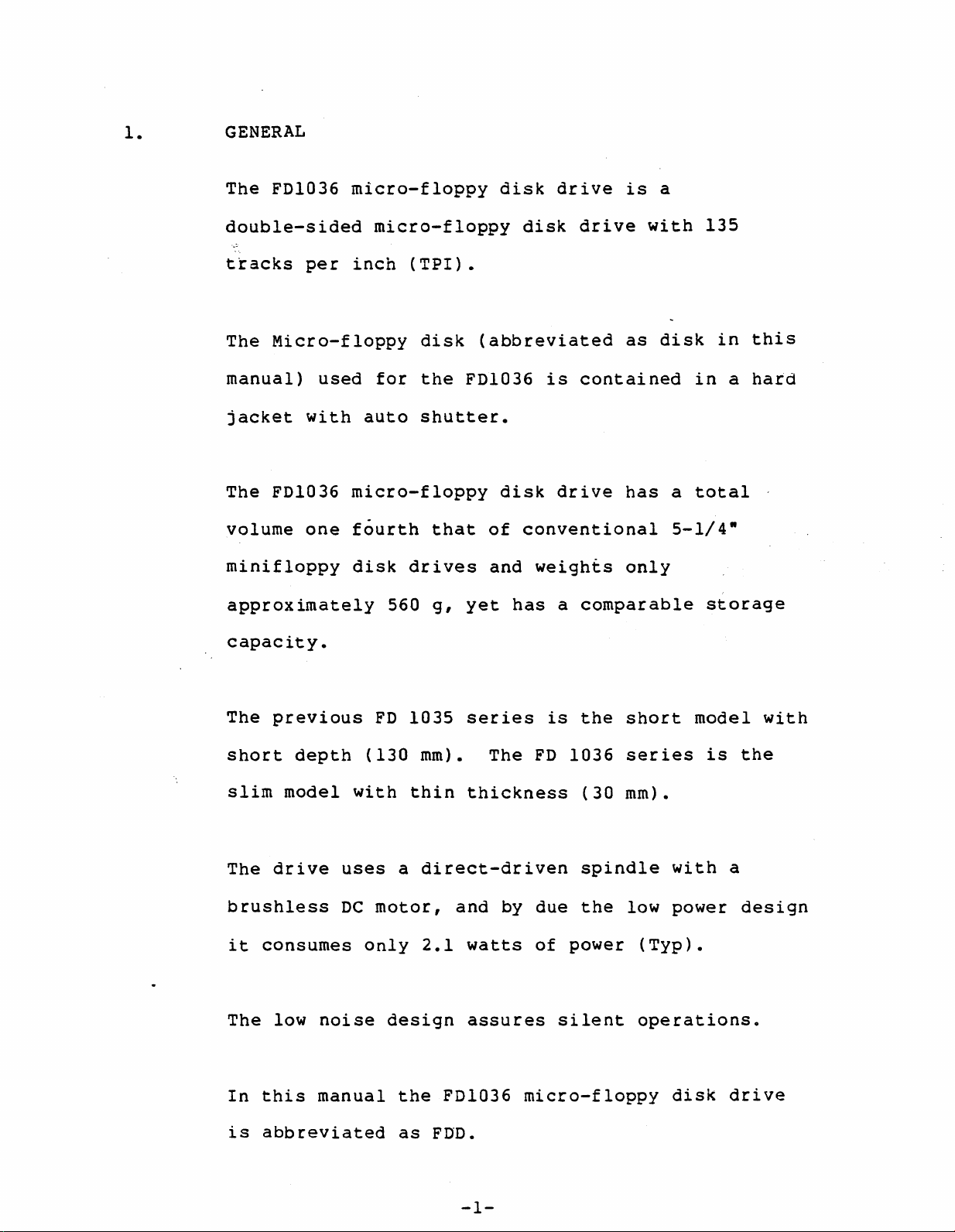
1.
GENERAL
The
FDl036
micro-floppy
disk
drive
is
a
double-sided
tracks
The
manual)
jacket
The
volume
per
Micro-floppy
used
with
FDl036
one
minifloppy
approximately
capacity.
micro-floppy
inch
(TPI).
disk
for
the
auto
shutter.
micro-floppy
fourth
disk
560
that
drives
g,
disk
(abbreviated
FDI036
disk
of
conventional
and
weights
yet
has
drive
is
contained
drive
a
comparable
with
as
has
only
disk
a
5-l/4
135
in
in
a
total
w
storage
this
hard
The
previous
short
slim
The
model
drive
brushless
it
consumes
The
low
In
this
is
abbreviated
depth
noise
manual
with
uses
DC
only
FD
(130
a
motor,
design
the
1035
series
mm).
thin
thickness
direct-driven
and
2.1
watts
assures
FDI036
as
FDD.
is
The
FD
by
due
of
micro-floppy
the
1036
(30
spindle
the
power
silent
short
series
mm).
with
low
power
(Typ).
operations.
disk
model
is
a
drive
with
the
design
-1-
Page 8
2.
•
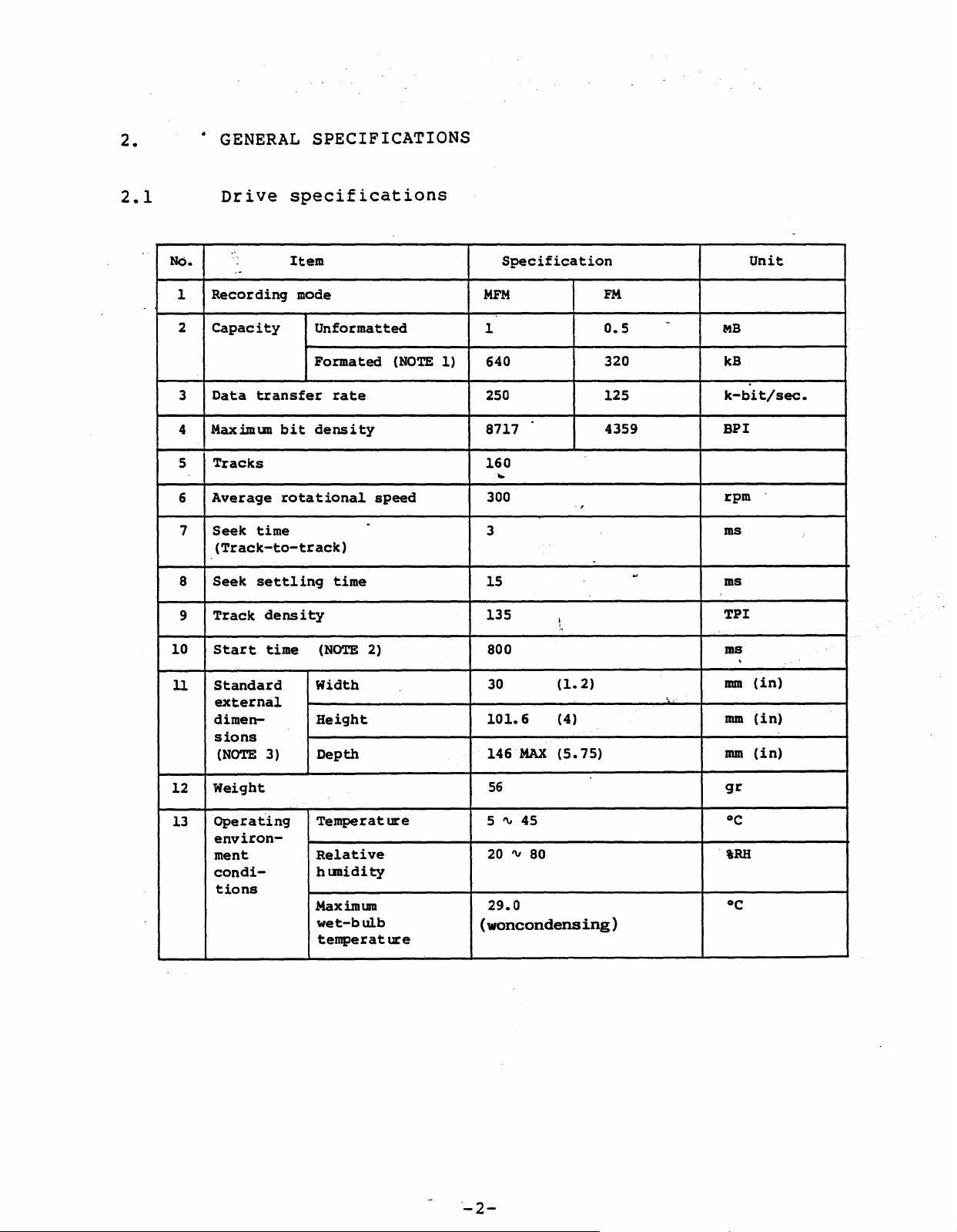
GENERAL
SPECIFICATIONS
2.1
Drive
NO.
Recording
1
2
Capacity
Data
3
Maxim\D1
4
5
Tracks
Average
6
Seek
7
(Track-to-track)
8
Seek
Track
9
10
Start
Standard
11
external
dimensions
(NOTE
.-
--
specifications
Item
mode
Unformatted
Forma
transfer
bit
density
rotational
time
settling
density
time
3)
(NOTE
Width
Height
Depth
rate
time
ted
.
2)
(NOTE
speed
1)
Specification
MFM
1
640
250
8717
160
~
300
3
15
135
800
30
101.6
146
MAX
" ,
L
(1.2)
(4)
(5.75)
FM
0.5
320
125
4359
Unit
-
MB
kB
k-bit/sec.
BPI
rpm
ms
.,
ms
TPI
ms
\
(in)
mm
mm
(in)
mm
(in)
12
13
Weight
Operating
environment
condi-
tions
Temperat
Relative
h\D1idity
Max
im
1.DIl
wet-bulb
temperat
ure
ure
56
45
5
'"
20'"80
29.0
(woncondensing)
"-2-
gr
°C
iRH
°C
Page 9
No
•.
Item
Specification
Unit
14
Power
supply
·Vo1tage
(V)
Start
(NOTE
up
4)
current
Steady-state
current
(NOTE
5)
requirement
15
16
17
Power
Heat
Reli-
dissipation
.".
output
ability
18
,"
Disk
life
+12
+5
MTBF
MTTR
Device
Soft
Hard
Seek
ratio
(NOTE
life
errors
errors
.
error
Less
60
0.3
0.26
6)
12000 (Under
~e
0.5
15000 poa
(De
10
or
10
10
3.0
than
condition)
sign
-9
(Not
less
-l.Z
_6
x 10
0.1
standard
or5years
life)
including
retry
6
90
200
2.1
1.8
2
attempts)
..
..
rnA
rnA
W
kcal/h
-
poa
h
Times/bit
Times/bit
Times/seek
Pass
count/
track
.
19
20
Disk
Drive
environment
Temperature
Relative
hunidity
M.ax
im
lU'It
wet-bulb
temPe
rat
ure
Largest
temperat
ure
Operating
4
tV
46
(39 "'115)
20
'" 80
29
(84)
20
(59)
Double
diskette
Non-operating
(Storage)
-20
(-4
10
40
sided
3.5"
specified
by
Transporting
(Packing)
'" 50
"'122)
-40
(-40
'" 90 5 '" 95
45.
(104) (113)
30
(86)
30
(86)
NEC
'" 60 '
"'140)
Unit
°C
(OF)
%RH
°C
(OF)
°C/h
(OF/h)
-3-
Page 10
No
.
Item
Specification
Unit
Allowable
vibration
(Except
resonance
point)
(NOTE
Allowable
shock
(Less
10
7)
ms)
at
than
NOTEl:
2:
3:
4:
0.5
(Less
100
Hz)
5
16
Time
Dimensions
bezel.
If
ON
than
sectors/track,
until
the
disk
signal
2
(Less
100
15
READY
not~nc1uding
is
than
Hz)
after
is
not
invalid.
256
inse
bytes/sector
2
(Less
100
40
MOTOR
that
rted
than
Hz)
-
ON
of
0 r
the
the
G
G
time
front
MOTOR
5:
6:
7:
When
Under
(1)
FDD
standard
Drive
time
(2)
Actual
time
(3)
Disk
ejection
(4)
(5)
Motor
Average
per
Excitation
is
in
service
(POH)
head
(R/W
insertion/
ON/OFF
use
disk
in
READY
use
load
time)
time
three
status.
,I
conditions
directions
8
h,Lday
0.5
h/day
25
times/day
300
times/day
2
h/day
(4
disks/day.drive)
one
R/W
test
8:
by
our
Between
FDD
SG
tester
and
-4-
FG:
for
0
90Kn (DC)
to
79
track
Page 11
2.2
DRIVE
The
major
functions:
STRUCTURE
component
of
FDD
have
the
following
(1)
(2)
(3)
Base
Constructs
Spindle
Rotate
spindle
spindle
driving
Head
carriage
Contains
across
side
one
motor
the
motor.
with
pin.
a
the
is
the
frame.
assembly
~
The
a
magnet
assembly
pair
of
disk.
dislocated
directly
disk
and
magnetic
The
R/W
8
by
is
is
heads
gap
tracks
using
set
driven
of
inner
the
to
by
facing
the
DC
the
a
head
than
on
(4)
that
Step
Move
for
of
motor
the
head
the
head
carriage
position.
on
Assy
side
by
zero.
using
the
steel
belt
-5-
Page 12
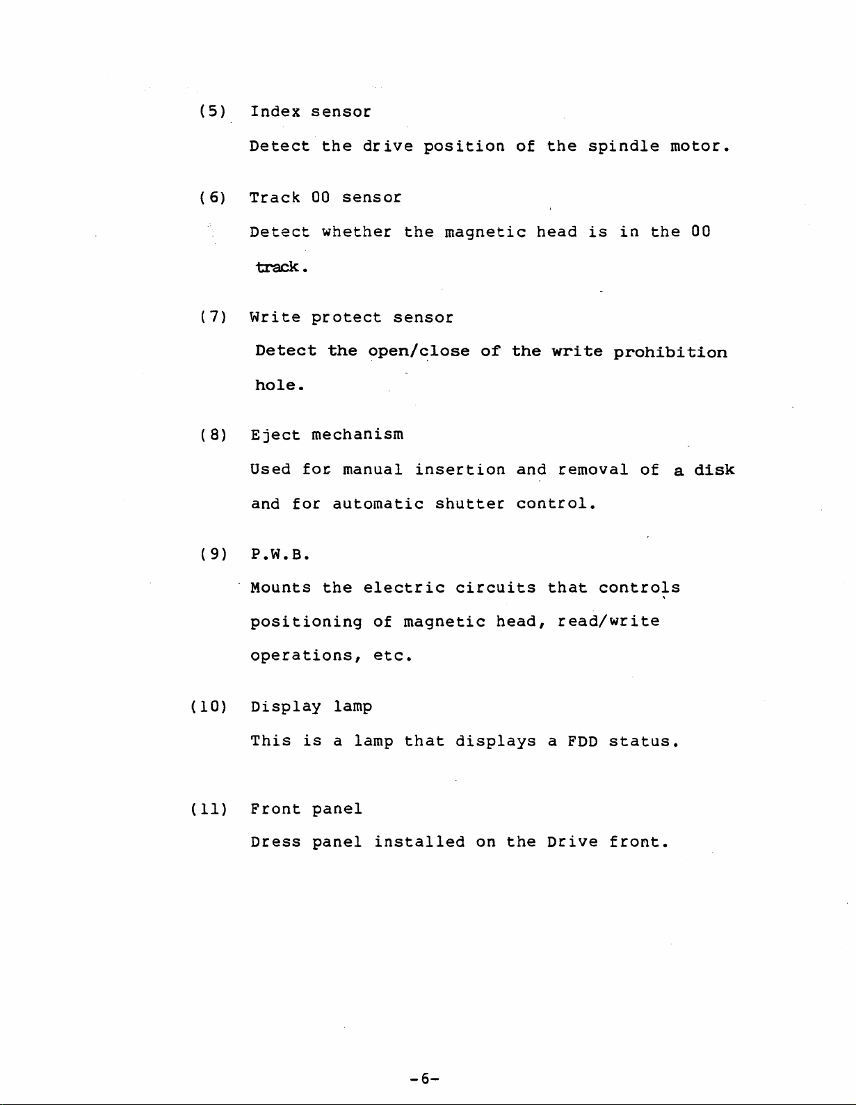
(5)
Index
sensor
(6)
(7)
(8)
Detect
Track
Detect
track.
Write
Detect
hole.
Eject
Used
and
the
00
sensor
whether
protect
the
mechanism
fo~
manual
for
automatic
drive
the
sensor
open/close
insertion
position
magnetic
shutter
of
of
the
head
the
write
and
control.
spindle
is
removal
motor.
in
the
prohibition
of
a
00
disk
(9)
(10)
(11)
P.W.B.
Mounts
positioning
operations,
Display
This
Front
Dress
is
panel
panel
the
lamp
a
electric
of
etc.
lamp
installed
circuits
magnetic
that
displays
on
head,
the
that
controls
read/write
a
FDD
Drive
status.
front.
-6-
Page 13
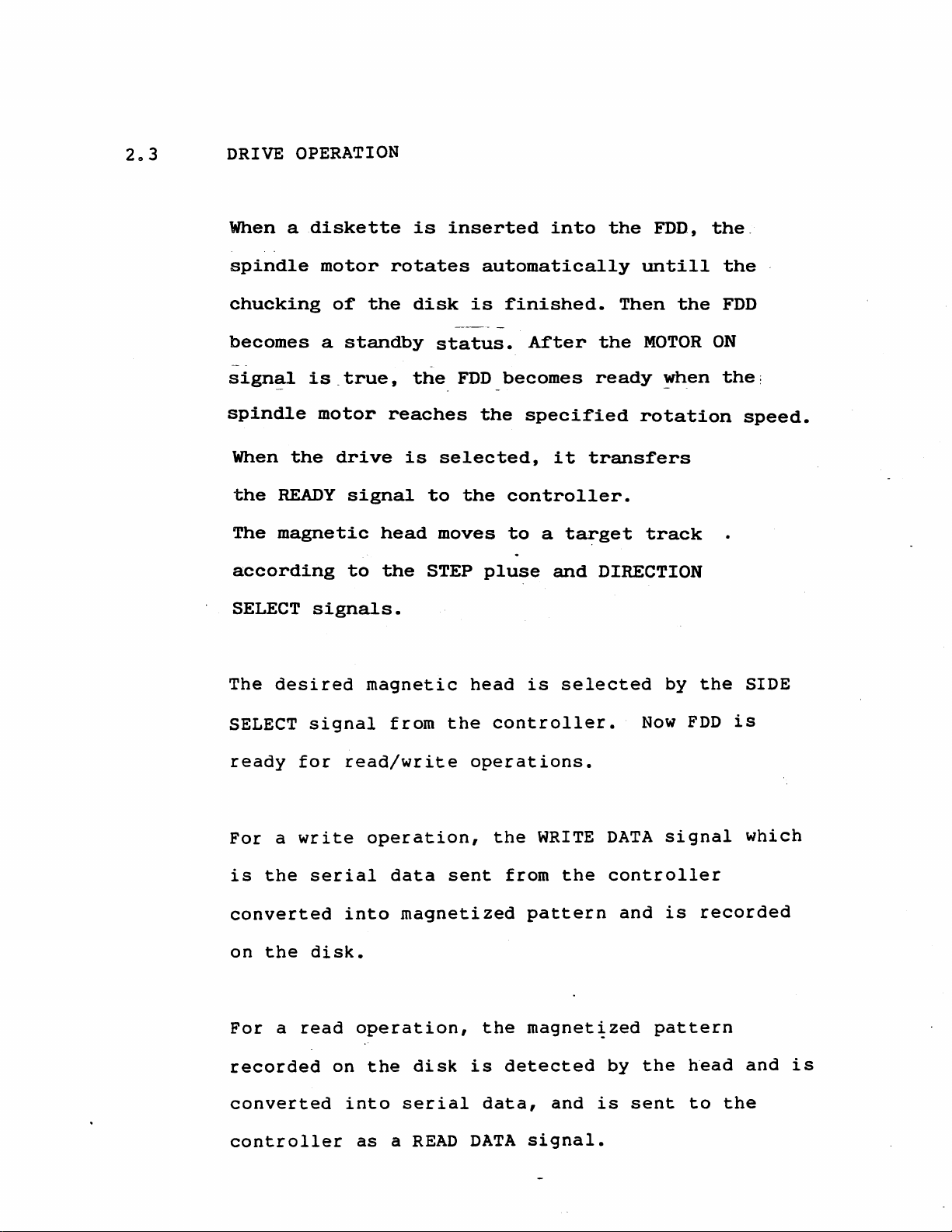
203 DRIVE OPERATION
When a
spindle
chucking
becomes
sign~l
spindle
When
the
READY
The
magnetic
according
SELECT
diskette
motor
a
is.true,
motor
the
signals.
of
the
standby
drive
signal
to
is
rotates
disk
the.
reaches
is
head
the
inserted
automatically
is
status.
FDD_becomes
the
selected,
to
the
moves
STEP
pluse
into
finished.
After
specified
it
controller.
to
a
target
and
the
FDD,
untill
Then
the
MOTOR
ready
~hen
rotation
transfers
track
DIRECTION
the
the.
the
FDD
ON
the:
speed.
The
desired
SELECT
ready
For
a
is
the
converted
on
the
For
a
recorded
converted
signal
for
write
serial
disk.
read
magnetic
from
read/write
operation,
data
into
operation,
on
the
into
head
the
operations.
sent
magnetized
disk
is
serial
is
controller.
the
WRITE
from
pattern
the
magnet~zed
detected
data,
and
selected
DATA
the
controller
by
is
and
sent
by
Now
signal
is
pattern
the
the
FDD
is
recorded
head
to
the
SIDE
which
and
is
controller
as
a
READ
DATA
signal.
Page 14

2.4
DISK SPECIFICATIONS
No.
1
2
3
4
5
6
7
Media
Prod
Number
uct
type
name
of
Recording
Number
per
Disk
of
disk
cartridge
Operating
environment
conditions
Item
disks
surfaces
total
size
Temperat
-
Relative
hunidity
Wet-bulb
temperature
Temperat
gradient
External
Magnetic
tracks
ure
ure
field
3.5-
double
specified
NEC
micro
10 '"
~
'1
20oC/h
4000
Specification
sided
by
NEC
floppy'_disk
90
x 94
60°C
8 tV
~.
29°C
MaximlDll
MaximlDll
(50
oersted)
A/m
(50
80%
-
\<
mediun
160
mm
'"
140°F)
RH
(84°F)
(36°F/h)
1
2
or
less
Note
Leave
minutes
the
in
environment
disk
the
at
drive
before
least
operating
use.
30
-8-
Page 15

2.5
DISK
STRUCTURE
The
floppy
withinside
disk
surface
polyethylene
magnetic
cloth
or
The
itself
and
dust.
disk
to
write-protect
The-disk
disk
of
is
which
protection.
terephthalate
layers.
protects
The
has
a
th~
hard
metal
spindle.
hole
construction
contained
liner
The
liner
the
jacket
hub
and
is
in
sheets
The
base
consists
disk
surfaces
is
made
wihch
The
hard
automatic'
shown
disk
is
in
a
hard
are
uses
coated
of
used
jacket
shutter.
Figure
jacket
provided
a
with
of
unwoven
from
ABS
to
scratch
resin.
secure
has
2.1.
for
a
-9-
Page 16

Figure
2.1
shows
the
disk
structure.
I.
Fig.
2.1
90
Disk
o
I
.I
Structure
-10-
Page 17

3.
INTERFACE
3.l
GENERAL
FDDIs
parallel
of
depends
daisy-chain
up
Signal
each
controller
(a)
FDD
to
FDD.
Parallel
may
Is
4
line
DESCRIPTION
be
connected
or
daisy-chain
which
on
dividual
FDDIs.
The
can
connection,
termination
basic
is
shown
connection
be
connected
system
FDD
in
to
its
controller
configuration.
and
controller.
each
controller
resistors
connection
Figure
3.i.
to
one
are
·controller
provided
to
the
in
The
can
either
number
For
control
on
Controller
Signal
Power
Signal
cable
cable
cable
.1
R
FDD
#0
I
maximum
R
FDD
il
length
R:
1 m
u
R
FDD'
#2
Terminating
resistor:
2K
R
FDD
#3
0
-11-
Page 18

(b)
Daisy
Chain
connection
.""
.0
Controller
Signal
cable
Signal
Power
-
total
cable
cable
\/
R
FDD
#0
I
length
...
maximum
\/
R
FDD
#1
I
R:
length
\/
R R
-
FDD
#2
Terminating
resistor
1 m
\
FDD
2K
#3
n
Fig.
3.1
Basic
Connection
Modes
~
-12-
Page 19

3.2
PHYSICAL SPECIFICATIONS
The
FDD
is
connected
to
its
controller
through
a
signal
terminal
connector
connector
is
provided
locations
and
a
for
are
power
frame
shown
connector.
ground.
in
Figure
A
The
3.2.
faston
-13-
Page 20

Power
plug
connector
Si
qnal
receptacle
connector
Signal
lu
connector
Fig.
3.2
Connector
Locations
-14-
Page 21

3.2.1
Signal
The
~ypes
following
and
shows
Pin
Configuration
the
signal
connector
pin
PWB
part
surface
configuration
~~""..MJ---!-~J--""--,,--,,,--,,~
Signal
MOTOR
IN
USE
ON
name
1
PIN
on
No.
Input
Input
the
I/O
FD
33
Signal
signal
signal
1036:
PIN
No.
.....
....c;.-,,--,-....c;.~M-"-"""'-..J-J
Pin
Nunber
~
';2
4
Pin
Nunber
1
3
Signal
Name
GND
GND
l~·
DRIVE·
SELECT
INDEX
DRIVE
DRIVE
DRIVE
SELECT
SELECT
SELECT
(MOTORON1)
MOTOR
ON
DIRECTION
STEP
WRI'lE
WRI'm
TRACK
WRITE
READ
SIDE
DATA
GATE
00
PROTECT
DATA
SELECT
READY
3
0
1
2/
SELECT
Input
Output
Input
Input
Input
Input
Input
Input
Input
Input
Output
Output
Output
signal
signal
signal
signal
signal
signal
signal
signal
signal
signal
signal
signal
signal
Inputsignal
Output
signal
6
8 7
10
12
14
11
13
16 15
18
20
22
24
26
28
30
32
34
17
19
21
23
25
27
29
31
33
5
~
GND
GND
9
GND
GND
GND
GND
GND
GND
GND
GND
GND
GND
GND
GND
GND
.
-15-
Page 22

FG
and
SG
processing
as
follows:
3.2.2
SG
Impedance
R =
100
POWER
The
following
Te
kn
CONNECTOR
configuration:
R
rminator
(~
10%),
AND
shows
FG
C =
O.l~F
PIN
CONFIGURATION
the~power
Printed
circuit
+_
8400%%)
(
connector
board
pin
Fig.
Table
3.3
Pin
EB
EB
3
2
Connector
Connector
3.1
1
Power
Power
number
1
2
3
4 +12 V
EB
4
in
Supply
+5
Configuration
Pin
Assignments
voltage
V
DC
GND
GND
DC
.
-16-
Page 23

3.2.3
CONNECTOR
TYPE
Housinq:
Pins:
The
the
following
signal
equivalent
171822-4
170262-1
Power
pluq
connector
and
connector
by
Japan
connector
power
AMP.
Co.,
type
connections
types
Ltd.
may
are
recommended
for
also
be
the
FDD;
used.
Power
rece
for
connector
tacle
Signal
receptacle
connector
Si
qnal
lu
Socket:
PS-34SEN-D4Pl-1C-N
(closed-end
PS-34SEN-D4Pl-1D-N
(daisy-chain
both
by
Electronics
Co.,
Ltd.
or
equivalent
Cable:
3365-34
Sumitomo-3M,
or
equivalent
Fig.
type)
type)
Japan
Industry,
by
Co.,
3.4
connec
Aeronotic
NOTE
1
Ltd.
Connector
tor
Locations
and
Recommended
Models
-17-
Page 24

3.3
ELECTRICAL
SPECIFICATIONS
3.3.1
3.3.2
SIGNAL
All
the
TRUE
FALSE
LEVEL
the
input/output
following
=
Logical
=
Logical
DRIVER/RECEIVER
The
driver
controller
capable
which
is
of
obtaining
electrical
ftOft
Wlft
outputs
an
open
signals
(LOW
(HIGH
collector
sink
are
at
specifications:
level)
level)
signals
0,
+2.5
from
output
current
l
of
TTL
level
to
+0.4
to
+5.25
FDD
to
circuit
maximum 40
with
V
V
the
mA
at
from
gate'
LOW
level.
the
terminating
The
controller
receiver
to
with
FDD
2k
is
Ohm.
which
a
receives
Schmitt
signals
trigger
-18-
Page 25

·Con
troller
Cable
1.0
m
length
(Max.)
+5V
FDD
7438
equivalent
or
Driver
Receiver
Fig.
+5V
3.5
TiT
rf1
TiT
(MIN)
;;;-
Driver/Receiver
i7T
\h
m-
;;;-
Circuit
LS14
equivalent
7438
-equi
or
valent
Driver
Example
or
-19-
Page 26

3.4
Input
Signals
3.4.1
3.4.2
DRIVE
DRIVE
SELECT
SELECT
specified
level
selects
effective
FDD
is
specified
selection
STEP (STP)
Pulse
signal
direction
0
to
0
to
FDD.
the
the
input/output
plugs
which
specified
3
(DSO
3
are
signals
Setting
corresponding
by
shorting
a
to
3
on
moves
by
the
to3)
one
of
lines.
one
the
PWB.
the
magnetic
di~ection
for
DSO
FDD,
of
selecting
to
DS3
which
the
head
select
DX
to
makes
in
a
LOW
the
signal.
LOW
to
HIGH
head
input
moves
pulses.
conditions.
The
head
level
over
begins
of
as
Figure
this
many
moving
signal.
cylinders
3.6
shows
at
the
the
The
as
the
pulse
rising
magnetic
number
timing
from
of
-20-
Page 27

u U
u
3.4.3
DIRECTION
Signal
movement.
toward
toward
This
instructing
the
the
signal
JTJ_Tl
Fig.
SELECT
The
outer
inner
must
Tl:
T2:
3.6
HIGH
3 ms
0.8
STEP
(DIR)
the
level
tracks
tracks.
be
switched
_.I
min.
~s
~
Pulse
direction
indicates
and
2 ms
Specification
of
the
LOW
definitely
magnetic
the
direction
~level
o.all','S
head
indicates
3.4.4
before
STEP
SIDE
Signal
read.
the
This
the
the
signal.
SELECT
selecting
The
side
read/write
·0·
signal
trailing
(SSL)
HIGH
of
must
operation.
one
level
the
be
edge
of
disk
switched
(positive
the
selects
and
heads
the
the
100IIs
going)
used
magnetic
LOW
level
befor
for
of
the
write
head
selects
start
or
on
of
-21-
Page 28

3.4.5
WRITE
GATE
(WGT)
3.4.6
This
data
LOAD
signal
when
signal,
start
gone
to
WRITE
Pulse
the
disk.
to
LOW
head
of
changes
magnetization
writes
at
HIGH
switch
positioning,
HIGH
DATA
signal
level.
(WDT)
that
Every
level,
direction,
the
data
level.
the
for
supplies
time
write
on
th~
1 ms
the
when
Do
SIDE
data
signal
current
which
disk.
at
not
SELECT
after
changes
LOW
turn
this
to
be
changes
in
the
level
off
signal,
~ignal
written
from.
~agnetic
the
and
the
reads
HEAD
or
has
to
HIGH
direction
Figure
3.7
shows
the
WRITE
DATA
specification.
-22-
Page 29

WDT
(PM)
2Tl
WDT
(MFM)
Fig.
I.
Tl:4-
T2:
3.7
Tl:
T:
Tl
4
1.1s
0.lS'V2.S
1.5Tl
./.
lJS
0.15
WRITE
~
2.5
DATA
lJS
J
lJS
(2Tl:
Pulse
(2Tl:
8
8 lJS ±
Specification
1.1s±25
25
ns)
ns)
3.4.7
MOTOR
The
when
The
to
1.
*
2.
3.
NOTE: *
ON
spindle
the
following
rotate
Plug
Plug
Plug
0
(MON)
motor
disk
the
1:
Interface
2:
Interface
3:
Interface
mark
delivery.
rotates
is
inserted.
signals
spindle
indicates
on
the
motor.
pin
pin
pin
setting
by
making
MON
14
(DRIVE SELECT
16
(MOTOR
2
(MOTOR
this
plug
position
ON
ON
can
signal
0)
1 )
be
when
LOW
used
2)
-23-
Page 30

3.5
Output
Signals
3.5.1
INDEX
Signal
is
output
the
output
The
reading
reference.
(IDX)
for
INDEX
(lDX)
indicating
once
pulse
edge
every
revolution.
specification.
of
the
u u
t-::
the
origin
pulse
on
is
the
Figure
used
dis~.
as
3.8
a
-....1
Tl
=1'V8m.s
T2=200
This
shows
±3ms
3.5.2
TRACK
When
heads
This
track
step
Fig.
00
at
are
signal
00
motor.
3.8
(TKO)
LOW
on
sensor
INDEX
level,
track
is
generated
and
Pulse
this
·00·.
the
Specification
signal
by
(excitation)
indicates
the
signal
from
phase
that
of
the
the
the
-24-
Page 31

3.5.3
READY
(RDY)
Signal
This
selected,
ti)
(ii)
(iii)
(NOTE) When
indicating
signal
DC
A
The
reached
MOTOR
disk
goes
if
the
power
is
rotational
the
ON
that
to
following
is
supplied.
mounted.
90t
of
spindle
signal
LOW
speed
the
FDD
is
level,
conditions
of
specification.
motor
ready
when
(5V,
the
is
to
the
l2V)-
floppy
rotating
operate.
FDD
are
is
satisfied:
disk
by
has
the
3.5.4
READ
Data
string.
Figure
normally
DATA
read
3.9
(RDT)
from
shows
recorded
a
disk
the
data
which
READ
is
is
DATA
read.
shaped
signal
into
obtained
a
pulse
when
-25-
Page 32

Read
(FM)
data
(ROT)
Read
(MFM)
3.5.5
data
(ROT)
T3
I.
T3
T4
Fig.
WRITE PROTECT
If
a
inserted
disk
3.9
with
into
./.
4llS
IllS
READ
(PRT)
the
T
3
1.5
(Typ)
±500ns
DATA
its
drive,
.1
Signal
WRITE
Specification
PROTECT
the
PRT
hole
line
2T3
uncovered
goes
.I
is
low,
which
places
the
FDD
in
-26-
the
WRITE
PROTECT
state.
Page 33

3.6
Interface
Signal
Timing
3.6.1
3.6.2
Step
Step
Track
Access
and
(STP)
00
Track
(TKO)
timing
00
u
u
II
2•5
ms
(max.)
1
ms
(min.
:
)
Write"gate
Step
Direction
(DIR)
(STP)
(NOTE)
(WGT)
select
An
interval
between
changes.
step
of
pulses
at
-
0.8
:L
3
least
1.1s~2
ms
when
ms
18
ms
(NOTE)
18
IDS
the
L
(min.
)
-i
is
required
direction
,
0.8
(min.
1.1s
)
-27-
Page 34

3.6.3
Write
Timing
Step
Side
write
3.6.4
Step
(STP)
select
gate
(STP)
Read
(SSL)
(WGT)
Timing
18
IDS
(min)
100'
..
.
1.1S
-\
(min.
,
.
11
I
ms
(min.)
U
JK
)
18
ms
-...----I~~~
(min.)
Side
Write
Valid.
select
gate
read
(SSL)
(WGT)
data
100
1 ms
1.1S
(min.)
(min.)
Valid
-28-
Page 35

3.6.5
Write
Data
Timing
3.6.6
J.6.7
Write
write
DRIVE
The
valid
gate
data
SELECT
drive
500
active.
Autochucking
Power
supp~
- 5 V
12
V"
(WGT)
(WDT)
control
ns
---
and
Output
after
Timing
and
that·the
8
~S
Signal
status
(max.)
DRIVE
Timing
signals
are
SELECT
8 l.lS
become
line
(max".)
is
x
Disk
Spindle
Index
Spindle
X
is
in
internal
signal
l
of
Ready
the
...
Chucking
FDD.
-
Status
Completion
-29-
Page 36

3.7
POWER
INTERFACE
3.7.1
INPUT
....
Table
sequence
A
POWER
3.2
Table
Voltage
Current
(NOTE
Ripple
3.2
Item
1)
voltage
SPECIFICATIONS
shows
for
Activating
Average
seek
Average
read/write
Average
standby
the
each
Input
(NOTE
when
when
when
(NOTE
DC
DC
Power
6)
time
2)
power
power
Specifications
.. +12V power
+12V1:5%
350
mA
IDA
140
90
IDA
to
~t
Less
than
200mVp~p
specifications
is
not
needed.
+5V
+5V.±5%
140
160
,~
200
0.1
M 60'mA
or
less
100mVp-p
....
power
mA
mA
mA
or
for
,
less
FDD.
NOTE
1:
2:
3:
4:
5:
6:
This
is
This
Data
power
in
Write
If
power
moving
inner
returned
Do
not
supply
Including
FDD
includes
is
protected
supply
operation.
supply
the
side
to
turn
by
average
ON/OFF
carriage
for
track
on
the
ripple
the
is
1
and
relay,
comsuming
spike
in
spite
when
charged
to
track,
0
immediately.
off
etc.
voltage.
voltage.
FDD
the
the
the
current.
of
DC
is
after
outer
carriage
power
not
or
is
-30-
Page 37

4.
OPERATING
PROCEDURES
4.1
4.2
4.3
The
basic
power
Setting
(1)
Removing
(1)
(2)
Display
on/off,
Insert
the
Make
finished.
To
press
operating
A
Floppy
Eject
the
sure
eject
the
Lamp
disk
the
button
Floppy
the
the
Eject
procedures
setting
Disk
diskette
disk
write/read
diskette
pops
button.
and
slowly
out.
from
for
FDD
removal.
into
operation
the
include
the
drive,
of
slot
FDD
just
the
until
has
The
It
Display
comes
on
lamp
while
indicates
the
FDD
the
FDD
status.
is
selected.~
-31-
Page 38

5.
EXTERNAL
SHAPE
AND
INSTALLATION
5.1
External
Figure
positions
..
0
+I
"!
t"'l
...
o
..
+l
0
"!
+1
...
~
0\
0
...
5.1
Shape
shows
.
146:
1
r
'r
(
and
0
s
•
70±a·S
the
60::°·5
-
+
Fitting
external
..
31±0.S
)
-
~
::
21
--
Hole
to.slS
Positions
shape
.-~
.~
6;: o.s
:~.S
s
4:O·
..
+1
and
..
~
~
0
...
~
+1
0
C'l
Q/
r&I
~
..
~
i~
~
Q
fitting
.
6.3%0.5
~
;n
X
32:tlt
21.9:O·
-
hole
s
4-Rl.2
:/
I
I
II!
0
+I
\0
M
8-4t4-40UNC
(NO'l'E
NOTE
Fig.
1)
+
-.1
1:
5.1
'+"
I
""
The
External
""
metric
-
70:!:D.S
60%O·s
screw
Shape
31:
type
and
o.s
2l.:!:0.s
...
-]]I
II""
.J
...
..
-,~
_4
is
also
Fitting
...
\.;.
0
+I
r,-
LJ
8.6
Unit
[1IIlIl]
available.
Hole
,
t
±o-.s
r
Positions
-32-
Page 39

5.2
Installation
(1)
FDD
(a)
(b)
(c)
may
be
Vertical
Vertical
Horizontal
o
installed
in
the
following
manners:
a
.
(a)
Consider
that
from
installing
it
CRT,
the
may
location
be
power
it
(b)
protected
supply,
inside
of
CRT.
FDD
against
etc.,
in
the
the
especially
(c)
system,
noise
so
when
-33-
Page 40

5.3
Recommended
Air
Flow
(1)
(2)
Installing
~
--==-c::=.
/ , / " 3
..-.L
nO
I
U·
D \
\
/"
/
~~
Installing
/_--
1
~
_/
one
Ventilator
two
/
\~
FDD
FDDs
Ventilator
NOTE:
o
\
I
Appropriate
ambient
considerably.
cooling
temperature
is
required
around
FDD
if
rises
the
-34-
Page 41

6.
PACKING
AND_TRANSPORTATION
(1)
(2)
For
external
material
make
to
Make
shock
sure
FDD.
sure
used
no
during
packing,
in
the
direct
that
FDD
transportation.
either
carrying
shock
will
will
sustain
use
in
the
of
be
transmitted
no
excessive
packing
FDD
of
-35-
 Loading...