

NEC FD1165 Maintance Manual

FDl165
Flexible
Disk
Maintenance
Drive
Manual
NEe
Info,mation
NEe
Systems,lnc.
819-000090-2001
10-82
LIABILITY
DISCLAIMER
NEe
Information
accordance
Systems,
is
affected
tion,
other
customer
factors.
compatible
mentation
Therefore,
application
warranted
This
time
may
manual
of
have
Systems,
features,
without
NEC
Information
use
by
tained
produced
from
NECIS.
Inc.
by
by
pr
inting,
been
Inc.
or
notice.
NECIS
herein
in
with
the
product
by
system
data
While
with
most
customers
the
suitability
must
NECIS.
is
as
updated
reserves
specifications
Systems,
employees
is
whole
Systems,
terms
configuration,
and
systems,
be
determined
complete
however,
the
property
or
in
Inc.
of
the
specification.
operator
NECIS
products
the
of
the
product
of
and
the
since
the
right
of
Inc.
and
has
customers.
of
part
without
products
applicable
control
specific
a
product
by
the
factual
information
that
time.
to
its
prepared
NECIS
are
Product
software,
of
are
may
vary.
customer
as
change
products
The
and
prior
warranted
NEC
Information
performance
the
the
system
considered
functional
for
a
and
possible
in
this
NEC
Information
the
at
this
document
information
shall
written
applica-
among
to
imple-
specific
is
at
manual
functions,
any
not
time,
be
approval
in
be
not
the
for
con-
re-
First
NEe
Printing
Copyright
Information
5
Militia
Lexington,
Printed
-
October
1982©
Systems,
Drive
MA
in
U.S.A.
1982
Inc.
02173
FEDERAL
COMMUNICATIONS
INTERFERENCE
COMMISSION
STATEMENT
RADIO
FREQUENCY
Although
require
Model
This
unit
limits
disk
FCC
FDl165.
for
specifications
are
designed
interference
Manufacturer's
to
Prevent
Manufacturer's
The
ing
user
and
1.
must
operating
Operate
manufacturer's
2.
Ensure
grounded
plied
rating,
has
a
Radio
drives
been
Class
for
to
provide
in
a
residential
Instructions
Freguency
Instructions
observe
this
the
that
wall
with
as
the
type
B
computing
Subpart
the
device:
equipment
instructions
the
outlet
the
unit
subsystem
following
tested
J
of
reasonable
installation.
and
Interference
following
in
unit
and
is
ond
device
Part
User's
strict
:is
that
used
type
components
statement
found
in
accordance
15
of
to
protection
Responsibilities
precautions
accordance
for
the
plugged
the
and
not
applies
comply
FCC
Rules,
against
in
model.
into
a
power
modified.
do
to
with
with
install-
with
properly
cord
not
the
the
the
which
such
the
sup-
3.
4.
5.
Ensure
factory
Make
affect
Rules.
Properly
state
that
installed
no
modification
its
maintain
of
repair.
the
meeting
unit
cover
the
is
set
to
the
equipment
ii
i.
always
on
the
equipment
specified
the
operated
unit.
limits
in
a
with
which
would
of
satisfactory
the
the
User's
The
ar
ising
ment
ference
determined
encouraged
following
others
user.
Responsibility
user
under
1.
2.
3.
4.
If
these
the
following
1.
has
from
his
to
by
to
measures.
not
mentioned
Change
antenna.
Change
Change
Change
a
ttempts
Line
the
ultimate
harmful
contiol.
radio
turning
try
in
in
in
in
devices:
isolation
radio-frequency
or
television
the
to
correct
All
are
orientation
orientation
location
equipment
are
unsuccessful,
transformers
responsibility
If
this
equipment
the
of
these
exclusively
of
of
equipment.
power
emissions
equipment
reception,
off
interference
responsibili
at
of
the
the
equipment.
source.
install
to
correct
does
and
the
receiving
from
cause
which
on,
by
ties
expense
one
the
one
or
problems
equip-
inter-
can
user
of
the
and
of
device
all
any
the
be
is
of
2.
3.
If
necessary,
experienced
gestions.
by
the
Federal
to
Identify
This
Office,
"Note:
to
is
interest
has
booklet
stop
causing
been
Line
Electro-magnetic
Washi'ngton,
The
operating
filters
the
radio/television
The
to
corrected."
user
Communications
and
is
operator
harmful
stop
user
Resolve
available
his
opera
shielding
should
may
D.C.
interference
of
find
Radio-TV
from
20402,
a
computing
device
tion
consult
technician
the
until
following
Commission
the
u.s.
Stock
upon
and
the
the
dealer,
for
to
Interference
Government
No.
device
finding
004-000-00345-5.
it
is
interference
additional
booklet
be
helpful~
may
that
in
be
the
NEC
Problems."
the
or
sug-
prepared
"How
Printing
required
device
public
problem
an
iv
CONTENTS
CHAPTER
1.1
1.2
1
GENERAL
DESC.RI
CONSTRUCTION
1.2.1
1.2.2
1.2.3
1.2.4
1.2.5
1.2.6
1.2.7
1.2.8
1.2.9
1.2.10
1.2.11
1.2.12
1.2.13
1.2.14
1.2.15
1.2.16
1.2.17
1.2.18
PTION•••••••••••••••••••••••••••••••••••
Base
Spindle
Dc
Carriage
Stepping
Head
Pop-Up
Index
00
Write
Media-In
Collet
Printed
Variable
,(Optional)
Display
Front
Movable
Door
INFORMATION
AND
FEATURES
Frame
Direct
Load
Sensor
Track
Protect
Panel
Lock
•••••••••••••••••••••••••••
Assembly
Drive
Read/Write
Motor
Cam
Feature
•••••••••••••••••••••••••
Sensor
Sensor
Assembly
Circuit
Frequency
Lamps
••••"•••·••••••••••••••••••
Door
Solenoid
••••~••••••••••••••••
•••••••••••••••••••••
Spindle
•••••••••••••••••••••••
Assembly
•••••••••••••••••••••••
••••••••••••••••••••••
Sensor
••••••••••••••••••••••
••••••••••••••••••••••
Board
Oscillator
••••••••••••••••••••••••
Handle
••••••••••••••••••
•••••••••••••••••••
Motor
Assembly
•••••••••••••••
•••••••••••••••••
(PCB)
••••••••
Heads
••••••••••
•••
1-1
1-2
1-2
1-2
1-3
1-3
1-3
1-3
1-4
1-4
1-4
1-4
1-4
1-4
1-4
.
1-4
1-5
1-5
1-5
1-5
1.3
CHAPTER
2.1
2.2
2.3
SPECIFICATIONS
2 INSTALLATION
PRELIMINARY INSPECTION .
UNPACKING
2.2.1
2.2.2
2.2.3
ENVIRONMENTAL
2.3.1
2.3.2
2.3.3
AND
Unpacking
Repacking
Preinsta11ation
Operating
Space
Mounting
••••••••••••••••••••••••••••••••
AND
OPERATION
REPACKING
Procedure
Procedure
REQUIREMENTS
Environment
and
Weight
•••••••••••••••••••••••••••••
•••••••••••••••••••••••
••••••••••••••••••
••••••••••••••••••
Inspection
••••••••••••••••••••
••••••••••••••••
Data
v
••••••••••••••••
•••••••••••
1-5
2-1
2-1
2-1
2-1
2-3
2-3
2-3
2-3
2-3
CONTENTS (cont'd)
Page
2.4
2.5
2.6
2.7
2.8
POWER
2.4.1
2.4.2
2.4.3
INTERFACE
TERMINATOR
DRIVE
OPTION
2.8.1
2.8.2
2.8.3
2.8.4
2.8.5
2.8.6
2.8.6.1
2.8.6.2
2.8.6.3
SUPPLy
Power
Power
Power
IDENTIFICATION
SELECTION
Head Load
Radial
Side
Write
File
Door
DR
DL
DH
••••••••••••••••••••••••••••••••••
Supply
Connec
Connector
CONNECTION
RESISTORS
••••••••••••••••••••••••••••••
Ready
Select
Protect
Unsafe
Lock
Jumpe r
Jumper
Jumper
Specifications
tor
••••••••••••••••••••••
Pin
Assignments
••••••••••••••••••••••••••
••••••••••••••••••••••••••
(DX)
Jumper
Jumper
Jumper
Jumpers
••••••••••••••••••••••••••••
••••••••••••••••••••••••••••
••••••••••••••••••••••••••••
SELECTION
(HL)
Jumper
Jumper
(RX)
(SS)
(FR)
(DL, DR,
••••••••••
••••••
•••••••••••
••••••••••••••••
•••••••••••••
••••••••••••••
(PR)
••••••••••••
••••••••••••••
DH)
•••••••
2-6
2-6
2-6
2-7
2-8
2-9
2-12
2-12
2-12
2-12
2-12
2-13
2-13
2-13
2-13
2-13
2-13
2.9
2.10
2.8.7
2.8.8
2.8.9
2.8.9.1
2.8.9.2
2.8.9.3
OPERATING
2.9.1
2.9.2
DIS
PLAY
2.10.1
2.10.2
LAMPS
In
Use
Rea
d Da
Busy
Busy
Busy
Busy
Inserting
Removing
Ready
Busy
Lamp
Lamp
Lamp
Lamp
THE
FDl165
•••••••••••••••••••••••••••••••••
Lamp
Lamp
Pins
taP
(US)
•••••••••••••••••••••
ins(RD)
Jumpers
On
During
On
During
On
During
••••••••••••••••••••••••••
a
Flexible
a
Flexible
•••••••••••••••••••••••••••
••••••••••••••••••••••••••••
• • • • • • • • • • • • • • • • • •
(BU,
BS)
Head Load
Drive
In
Use
Disk
Disk
•••••••••••
••••••••
Select
•••••••••••
••••••••••••
•••••••••••••
•••••
2-14
2-14
2-14
2-14
2-15
2-15
2-15
2-15
2-16
2-16
2-16
2-17
vi

CONTENTS (cont'd)
CHAPTER
3.1
3.2
3.3
3.4
3
INTERFACE
BASIC
OPE:RATIONAL
ELECTRICAL
3.2.1
3.2.2
3.2.3
INPUT
3.3.1
3.3.2
3.3.3
3.3.4
3.3.5
3.3.6
3.3.7
3.3.8
3.3.9
3.3.10
OUTPUT
SIGNALS
SIGNALS
INFORMATION
DESCRIPTION
INTERFACE
Signal
Levels
Driver/Receiver
Interface
Lines
••••••••••••••••••••••••••••.••••
Drive
Head Load
Step
Direction
Side
Write
Write
Low
File
In
(STP)
Select
Write
Unsafe
Use
Select
(HDL)
•••••••••••••••••••••••••••
Select
Gate
Data
Current
(USE)
•••
•••••
.....................
••.•••••••••••••••••••••
Circuits
•••••••••••••
••••••••••••••••••••••
1
Through
4 (DSXl
••••••••••••••••••••••
(SSL)
(WGT)
(WDT)
Reset
•••
(DIR)
••••••••••••••••••••
•••••••••••••••••••••
•••••••••••••••••••••
It
•••••••••••••••••••••
•••••••••••••••
(LWC)
(FUR)
••••••••••••••
••••••••••••••
.
................
to
4).
3-1
3-2
3-2
3-2
3-3
3-3
3-3
3-4
3-4
3-4
3-4
3-5
3-5
3-5
3-6
3-6
3-6
3.5
3.6
3.4.1
3.4.2
3.4.3
3.4.4
3.4.5
3.4.6
3.4.7
3.4.8
VFO
INTERFACE
3.5.1
3.5.2
3.5.3
3.5.4
INTERFACE
3.6.1
3.6.2
3.6.3
3.6.4
3.6.5
3.6.6
Index
Tr
ack
(IDX) .
00
Dual-Sided
Ready
File
Read
Write
(ROY)
Unsafe
Data
Protect
DiskChan
SIGNALS
Modified
(MFM)
VFO
••••••••••••••••••••••••••••••
Synchroni
Standardized
Wi
ndow
TIMING
Power
Drive
Step
Access
Wr
i
te
Read
(WID)
••••••••••••••••••••••••
On
Select
and
•••••••••••••••.•••••••••••••••
.••••••••••••••••••••••••••••••••
(TKO)
(TSD)
•••••••••••••••••••••
••••.~•••••••••••••••••••••
(FUS)
••••••••••••••••••••
(ROT)
ge
(PRT)
(DCG)
••••••••••••••••••
••••••••••••••••••••
•••••••••••••••••••••••••
Frequency
zation
Read
Modulation
(SYC)
Data
(SRD)
Mode
••••••••••••
•••••••••
•••••••••••••••••••••••••
Sequence••••••••••••••••••••
•••••••••••••••••••••••••
Track
00
••••••••••••••••••••
3-6
.
3-7
3-7
3-7
3-7
.
3-8
3-8
3-8
3-9
3-9
3-9
3-9
3-9
3-10
3-10
3-10
3-10
3-11
.
3-11
3-12
vii
CONTENTS (cont'd)
CHAPTER
4.1
4.2
4.3
4.4
4
MAINTENANCE
PREVENTI
VE
MAINTENANCE
MAINTENANCE
REMOVAL
4.4.1
4.4.2
AND
PCB
Collet
and
4.4.3
Carriage
Replac
4.4.4
4.4.5
Head Load
C~m
Write
Sensor
4.4.6
Optical
and
4.4.7
Sensor
and
Replacement
4,,4.8
Removing
Brushes
4.4.9
.4
.4.10
4.4.11
4.4.12
4.4.13
Armature
Spindle
Front
Picker
Pop-Up
Replacement
4.4.14
4.4.15
Guide
Checking
Feature..............................
4.4.16
Door Lock
Replacement..........................
MAINTENANCE
TOOLS
PARTS
•••••••••••••••••••••••••••••
•••••••••••••••••••••••••••••
REPLACEMENT
Removal
••••••••••••••••••••
Assembly
Adj
ustment••••••••••••••
Assembly
ement
••••••••••••••••••••••••••
Cam
Removal
and
Protect
Removal
Tachometer
Replacement
Cable
Index
Sensor
••••••••••••••••••••••••••
and
••••••••••••••••••••••••••••••
Removal
Assembly
Panel
Rod
Removal
Removal
Assembly
••••••••••••••••••••••••••
Rail
Removal
the
Solenoid
••••••••••••••••••••••••
PROCEDURES
Removal,
Removal
Assembly
Replacement
Sensor
and
and
Replacement
Sensor
••••••••••••
Replacement,
and
and
Head
••••••••••
Media-In
Removal
•.••••••••••••••••••••
Assembly
Removal
Replacing
(LED
the
Assembly
and
Carbon
•••••••••••••••••••••
Removal
•••••••••••••
••••••••••••
and
Replacement
Removal
and
•••••••••••••••••••
Operation
of
Removal
the
and
"
"
••••••••
•••••••
,
•••••
Pop-Up
•••••
Load
•••
4-1
4-1
4-1
4-2
4-2
4-3
4-6
4-8
4-9
4-10
4-11
4-14
4-15
4-16
"
4-17
4-17
4-18
4-19
4-19
4-20
CHAPTER
5.1
5.2
5.3
5
ADJUSTMENTS
DIAGNOSTIC
5.1.1
5.1.2
5.1.3
HEAD
TEST
UNLOAD
PO
INTS
TESTS
Auto
Auto
Auto
DELAy
•••••••••••••••••••••••••••••••••••
••••••••••••••••••••••••••••••
Tap
Test
Seek
Seek
••••••••••••••••••••.•••
Test
and
•••••••••••••••••••••••
Auto
••••••••••
viii
Tap
"""""""
Test
II
" " " " " • " • "
.•••••••••
5-1
5-2
5-2
5-2
••
5-2
5-3
CONTENTS (cQnt'd)
5.4
5.5
5.6
CHAPTER
CHAPTER
ADJUSTMENTS
FLEXIBLE DISK
5.4.1
Head
Adj'ustment•••••••••••••••••••••••••••
5.4.2
5.4.3
O'l"HER
5.5.1
Azimuth
Index
ADJUSTMENTS
LED
and
5.5.2
5.5.3
00
Write
Adjus
5.5.4
TRIM
6
ILLUSTRATED
7
SCHEMATIC
POTS
Head
••••.-•••••••••••
AND
CHECKS
USING
THE
•••••••••••••••••••••••••••••••••
Radial
Check
Alignment
Alignment
Check
••••••••••••••••••••••••
Check
or
••••••••••••••••
Assembly/Index
Adjustment
Track
Sensor
Protect
•••••••••••••••••••••••
Sensor
Assembly
Check
or
Check
tment•••••••••••••••••••••••••••
Load
Check
PARTS
••••••••••••••••••••••
~
••••••••••••••••••••
BREAKDOWN
ALIGNMENT
or
Adjustment
~
••••••••••••
Check
Adjustment
or
••
••
5-3
5-4
5-6
5-7
5"'8
5-8
5-9
5-10
5
.....
10
5-11
ix
ILLUSTRATIONS
Figure
1-1
2-1
2-2
2-3
2-4
2-5
2-6
2-7
2-8
2-9
2-10
2-11
2-12
2-13
2-14
3-1
3-2
3-3
3-4
3-5
3-6
3-7
3-8
3-9
3-10
3-11
3-12
3-13
4-1
4-2
4-3
4-4
4-5
4-6
4-7
4-8
4-9
4-10
Title
FDl165
Unpack
Model
Vertical
Horizontal
On-End
Air
Cool
Power
Pin
Connec
Contact
In
terf
Terminator
on
Parallel
Closing
Unlocking
Fle'xible
Dr i ve r/Rec
Interface
Step
WGT
Write
Index
Read
Disk
Read
Step
Acce
Write
i ng
FDl165
Flow
i ng
Connector
and
tor
ace
the
Signal
Timing
Data
Signal
Data
Change
Data
and
Flexible
••••••••••••••••••••••••••••.••••••
Installation
Installation
Installation
Requirements
•••••••••••••••••••
Line
•••••••••••••••••••••••••••••••••••
Arrangement
Connector
Resistors
PCB
•••••••••••••••.•••••••••••••.••••
and
the
the
Disk
e i ver Ci r
Lines
••••••••••••••••••••••••••••••••••
Signal
Signal
and
Track
Disk
Physical
Drive
••••••••••••••••••
Dimensions
.••••••••••••••••••.•••
•••••••••••••••••••••
•••••••••••••••••••••••••
for
Natural
'
••••••••••••••••••
Location
Assignments
••••••••••••••••••.•
for
for
Edge
the
Connector
•••••••••••••••••••••••••
and
Jumper
Series
Door
Door
Configurations
of
the
FDl165
and
Removing
••••••••••••••
•••••••••••••••••••••••••••••••
cui
t s • • • • • • • • • • • • • • • • • • • •
•••••••••••••••••••.••••••••.
Timing
Timing
Signal
Window
••••••••••••••••••••••••••
Ximing
••••••••••••••••••••
•••••~•••••••••••••••••.•
Timing
00
Timing
Timing
••••••••••••••••.•.••
•.•••••••.•••••••••
Signal
Timing
••••••••••••••••••••
ssTiming•••••••••••••••••••••••••••••••
Timing
••••••••.••••••••••••••••••••.••
••••••••••••
Locations
the
ReadTiming••••••••••••••.••••••••••••••••••
Removing
Replacing
Head
Plate
Unload
Position
Carriage
Removing
Installing
Write
the
the
of
Assembly
the
Protect
Collet
Collet
Spring
the
Spring
Head Load
the
Head Load
or
Media-In
Assembly
Assembly
in
Relation
Plate
position
Cam
••••••••••••••••
•••••••••••••••
to
••••••••••••••••
on
the
••••••••••••••••••
Cam
Assembly
Sensor
Connections.................................
Installing
the
Write
Protect
or
Media-In
Sensor......................................
Removing
Tachometer
the
Sensor
Replacing
•••••••••••••••••••••••••••
the
Optical
Air
Power
••••••••••
••••••••••
Spring
Base
•••••••
••••••
Frame
Page
1-2
2-2
2-4
2-4
2-4
2-5
2-5
2-7
2-7
2-8
2-8
2-10
2-11
2-15
2-16
3-2
3-3
3-4
3-5
3-6
3-6
3-8
3-9
3-10
3-10
3-11
3-11
3-12
4-3
4-4
4-5
.
4-5
4-7
4-8
4-9
4-10
4-10
4-11
x
ILLUSTRATIONS (cont'd)
Figure
4-11
4-12
4-13
4-14
4-15
4-16
4-17
4-18
4-19
4-20
5-1
5-2
5-3
5-4
5-5
5-6
5-7
5-8
6-1
6-2
Removing
Installing
Removing
Removing
Removing
Removing
Adjusting
Removing
Removing
Adjusting
Location
Points
Head
Adjusting
Azimuth
Index
Waveforms
Track
Head
FDl165
G9NYF
Radial
Alignment
00
Load
Flexible
PCB
the
Sensor
the
a
Carbon
the
Armature
the
Spindle
the
Front
the
Picker
the
Pop-Up
the
Door
the
Door
of
Diagnostic
Alignment
Head
Waveform
at
TP7
Signal
Waveform
Assembly
Title
Cable
Index
Radial
••~•••••••••••••••••••••••••
Waveform
•••••••••••••••••••••••••••••
Disk
Sensor
Brush
•••••••••••••••••••••••
Assembly
Panel
Rod
Assembly
Lock
Lock
Waveform
and
TP10
••••••••••••••••••••••••••
Drive
••••••••••••••••••••••••••
Assembly
•••••••••••••••••
•••••••••••.•••••••••
•••••••••••••••
••••••••••••••••••••
••••••••••••••••••••
and
Solenoid
Solenoid
Test
Alignment
••••••••••••••••••••
•••••••••••••••••••
••••••••••••••••••
•••••••••••••
••••••••••••
Pins
••••••••••••••
•.••••••••••.
••••••••••
Guide
and
Test
Rail.
Page
4-12
4-13
4-14
4-15
4-16
4-17
4-18
4-19
4-20
4-21
.
5-1
5-5
5-6
5-7
5-8
5-9
5-9
5-11
6-5
6-7
Table
1-1
2-1
2-2
2-3
2-4
4-1
4-2
5-1
5-2
5-3
5-4
5-5
6-1
TABLES
Title
FDl165
Power
Power
Data
Ass
Door
Maintenance
Maintenance
Test
Adj
Head
Head
Index
List
Specifications
Supply
Connector
and
ignments•••••••••••••••••••••••••••••••••
Lock
Points
ust.ments
Radial
Azimuth
Alignment
of
Illustrations
Specifications
Part
Control
Jumper
Tools
Parts
and
•••••••••••••••••••••••••••••••••
Alignment
Interface
Combinations
Signals
Oscilloscope
Oscilloscope
•••••••••••••••••••••••
Number
••••••••••••••••••••••.••••
••••••.••••••••••••••••••••
•••••••••••••••••••••
Oscilloscope
•••••••••••••••••••••••
xi
••••••••••.••••••
••••••••••••.••••
Contact
•••••••••••••••
Settings
Settings
••••••••••
Settings.
•••..••
1-5
2-6
2-6
2-9
2-14
4-1
4-2
5-3
5-3
5-4
5-6
5-7
6-3
LIST OF ABBREVIATIONS
A
DIR
DCG
DLH
DSX
FDD
FM
FUR
FUS
HLD
IC
IDX
I/O
k
kg
LED
LSI
LWC
rnA
MB
MFM
ms
mV
PCB
POH
pp
PRT
ROT
ROY
rpm
SRO
SSL
STP
SYC
TKO
TSD
TTL
USE
Vdc
VFO
WDT
WGT
WID
~s
Ampere
Direction
Disk
Door
Change
Lock
Drive
Flexible
Frequency
File
File
Head
Unsafe
Unsafe
Load
Integrated
Select
Hold
Select
Disk
Modulation
Circuit
Index
Input/Output
1000
Kilogram
Light
Emitting
Large-Scale
Low
Write
Current
Milliampere
Megabyte
Modified
Frequency
Millisecond
Millivolt
Printed
Circuit
Power-On-Hours
Peak-To-Peak
Write
Read
Protect
Data
Ready
revolutions
Standardized
Side
Select
Step
Synchronization
Track
Two-Sided
Transistor
In
Volts
Variable
Write
Write
00
Disk
Transistor
Use
direct
Frequency
Data
Gate
Window
Microsecond
Drive
Reset
Diode
Integration
Modulation
Board
per
minute
Read
Data
current
Oscillator
Logic

CHAPTER 1
GENERAL INFORMATION
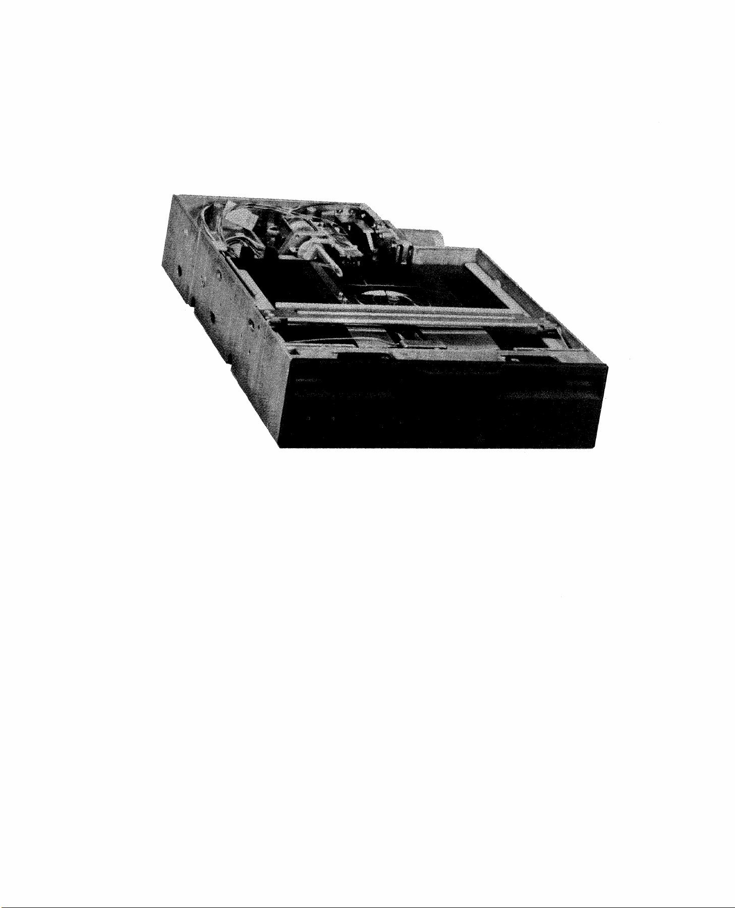
This
FDl165
and
chapter
parts
8-Inch
of
the
fications.
1.1
The
disk
or
the
ette
DESCRIPTION
Model
storage
FDl165
device
double-density
disk
that
drive
is
double-density
million
The
size
(2l7.2
inches
The
larger,
most
and
disk
bytes
apparent
light
rom)
high,
(335.0
drive
conventional
interface-compatible
measures
two
disk
conventional
one-half
drives
drive.
gives
Flexible
disk
Flexible
depends
used.
format,
(MB).
features
weight.
rom)
deep
has
can
an
drive
that
flexible
wi
by
2.28
all
units,
with
the
be
overall
Disk
uses
on
th
a
the
The
and
the
height
mounted
description
in
Disk
disks.
the
Drive,
detail,
Drive
single-
type
describes
or
The
and
dual-sided
maximum-storage
of
the
Model
disk
inches
weighs
drive
(58.0
only
features
and
~hem.
of
is
Because
'conventional
in
the
of
the
and
is
lists
a
compact
the
dual-sided,
storage
format
flexible
capacity
of
disk
capacity
FDl165
measures
rom)
7.7
and
are
8.55
wide
pounds
performance
media-compatible
the
Model
disk
same
space
the
features
speci-
magnetic
single-
the
is
its
inches
by
(3.5
FDl165
drives,
as
Model
of
disk-
and
1.6
small
13.20
kg).
of
and
one
a
The
Model
~PD765
(TTL)
supply
(for
the
motor)
FDl165
is
recommended)
interface.
that
TTL)
(see
must
and
Section
is
supply
microprocessor-controlled
mizes
(stepping
extremely
head
and
motor)
accurate
media
is
operated
The
+24
also
head
by
an
external
through
disk
and
Vdc
1.2.3).
head
wear.
drive
(for
a
Transistor
requires
control
the
The
loading
The
dc
disk
head
microprocessor-controlled
positioning.
1-1
Transistor
an
two
vol
direct
drive
mechanism
position
controller
external
tages,
drive
features
that
mechanism
+5 Vdc
spindle
to
(NEC
Logic
power
a
mini-
ensure
1.2
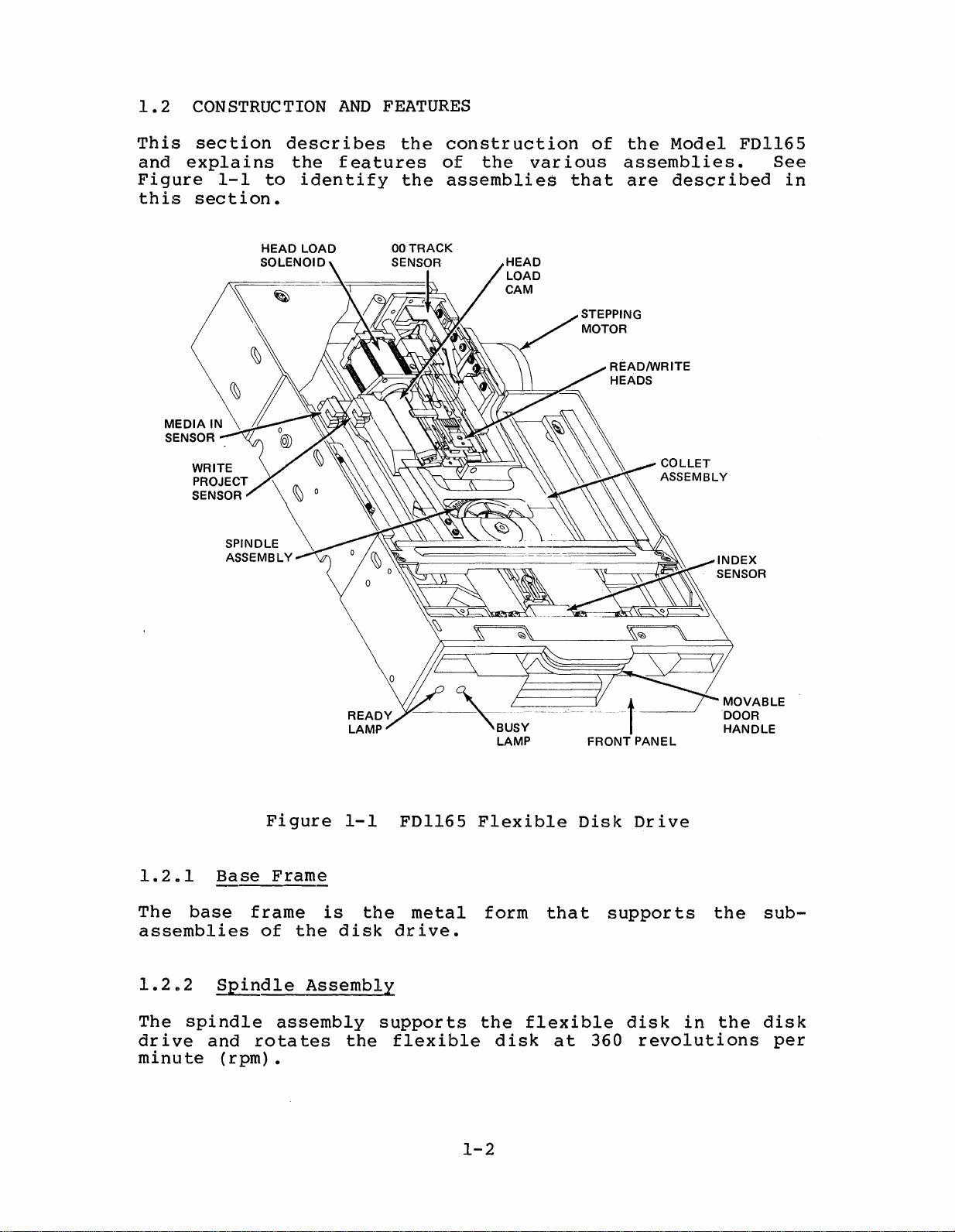
CONSTRUCTION
AND
FEATURES
This
and
Figure
this
section
explains
1-1
section.
describes
the
to
identify
HEAD LOAD
SOLENOID
features
the
construction
of
the
the
assemblies
various
that
of
the
assemblies.
are
Model
described
FDl165
See
in
1.2.1
The
base
assemblies
1.2b2
The
spindle
drive
minu
and
te
Figure
Base
frame
of
Spindle
rotates
(rpm).
Frame
is
the
Assembly
assembly
1-1
disk
the
FDl165
the
drive.
supports
flexible
metal
Flexible
form
the
disk
1-2
that
flexible
at
Disk
supports
360
Drive
disk
in
revolutions
the
the
sub-
disk
per
1.2.3
Dc
Direct
Dtive
Spindle
Motor
The
assembly.
associated
The
1.2.4
The
allowing
read
carriage
During
are
dc
•
•
•
•
spindle
read/write
from
held
direct
This
with
The
motor
inating
The
motor
be
The
concerns
The
un
Carr!
used.
its.
data
it.
assembly
the
away
motor
s.
motor
motor
motor
age
loading
drive
dc
motor
conventional
does
the
problems
consumes
Low-power,
uses
about
generates
has
Read/Write
heads
to
be
written
The
read/write
that
of
from
the
motor
not
direct
voltages
an
up-to-speed
touch
shifts
a
flexible
surface
(not
eliminates
ac
motor
use
drive
associated
less
inexpensi
Assembly
each
current,
and
less
to
the
heads
the
of
power
shown)
the
drives.
pulleys
ve
frequencies.
heat
time
Heads
side
heads
disk,
the
of
flexible
are
flexible
rotates
with
than
power
so
part
from
the
problems
or
these
conventional
that
than
of
700
the
flexible
disk
of
track
read/write
disk.
the
belts,
suppli
there
conventional
that
parts.
ms.
and
a
precision
to
spindle
elim-
es
are
disk,
to
track.
heads
are
ac
can
no
be
1.2.5
The
the
arrangement
each
shaft
carriage
1.2.6
The
heads
by
flexible
Stepping
stepping
carriage
pulse
rotates
Head
head
onto
a
microprocessor.
1/2
load
disk
motor,
assembly
provides
the
1.8
track
Load
the
and
Motor
stepping
degrees.
on
Cam
cam
flexible
reduces
under
with
fast
motor
the
Assembly
assembly
disk
This
wear
microprocessor
a
tensioned
and
flexible
receives,
This
(rotary
with
action
of
accura
action,
disk.
a
the
te
solenoid)
force
prevents
read/write
control,
steel
data
the
in
that
stepping
turn,
belt.
access.
lowers
is
controlled
damage
heads.
positions
This
motor
moves
to
For
the
the
the
1-3

1.2.7
Pop-Up
Feature
For
the
drive
the
from
1.2.8
The
that
Model
sided
1.2.9
The
the
1.2.10
The
a
write
notch,
the
easy
pop-up
when
flexible
the
Index
index
senses
FDl165
and
00
00
Track
00
track
Write
write
the
write
removal
feature
the
disk
sensor
the
dual-sided
Track
protect
protect
write
function
door
disk
drive.
Sensor
has
Sensor
sensor
(track
Protect
notch
of
the
ejects
is
protrudes
is
index
a
dual
flexible
detects
0,
sensor
function
operation
flexible
opened.
a
combination
position
index
side
Sensor
detects
on
the
is
disk
the
flexible
After
approximately
of
sensor
disks.
when
the
0).
the
flexible
disabled.
is
enabled.
from
ejection,
LED
the
to
read/write
presence
disk.
the
disk
1/2
and
flexible
detect
If
no
disk
from
the
inch
drive,
the
edge
(13
phototransistor
disk.
both
or
If
notch
single-
head
absence
there
exists,
is
disk
mm)
The
is
of
at
of
a
1.2~11
The
media-in
in
the
1.2012
The
the
collet
spindle
1.2.13
The
PCB
circuits
1.2.14
The
the
optional
interface
creasing
Media-In
disk
Collet
assembly
Printed
(not
of
Variable
the
sensor
drive.
Assembly
when
shown)
the
Variable
signals
overall
Sensor
detects
holds
the
door
Circuit
supports
disk
drive.
Frequency
reliability
the
the
is
closed.
Board
the
Oscillator
Frequency
to
the
presence
flexible
(PCB)
electronic
Oscillator
controller
of
(Optional)
the
disk
of
disk
a
drive
(VFO)
more
drive.
flexible
in
position
stable,
and
PCB
disk
on
logic
makes
in-
1-4
1.2.15
Displ~Lamps
Two
lamps
ready
1.2.16
The
front
attractive
1.2.17
The
movable
assembly.
1.2.18
The
door
remove
theieby
flexible
1.3
SPECIFICATIONS
on
and
busy
Front
Movable
Door
lock
the
preventing
disk.
the
front
states
Panel
panel
holds
appearance
Door
door
Lock
Solenoid
solenoid
flexible
of
for
Handle
handle
disk
data
panel
the
the
,when
(not
provide
disk
display
the
during
loss
front
closed,
shown)
or
a
drive.
lamps
of
makes
certain
physical
visual
the
engages
and
disk
it
drive
display
provides
drive.
the
impossible
operations,
damage
of
collet
to
the
an
to
the
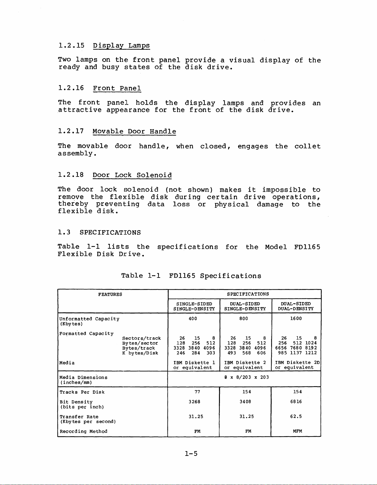
Table
Flexible
Unformatted
(Kbytes)
Formatted
Media
Media
Dimensions
(
inches/rom)
Tracks
Bit
Density
(bits
per
Transfer
(Kbytes
Recording
1-1
Capacity
Per
Rate
per
Disk
FEATURES
Capacity
Disk
inch)
second)
Method
lists
Drive.
the
Table
Sectors/track
By
tes/
by
sec
tes/D
Bytes/track
I<
specifications
1-1
tor
isk
FDl165
SINGLE-SIDED
SINGLE-DENSITY
128 256
3328 3840 4096 3328 3840 4096 6656 7680
246 284 303
IBM
or
400
26
15 8
Diskette
equivalent
77
3268
31.25
FM
for
Specifications
SPECIFICATIONS
DUAL-SIDED
SINGLE-DENSITY
800
512
26
128 256 512
493
1
IBM
or
8 x
Diskette
equivalent
8/203
3408
31.25
the
15
568 606
x 203
154
FM
Model
DUAL-DENSITY
8
256 512
985
IBM
2
or
FDl165
DUAL-SIDED
1600
15 8
26
equivalent
1024
8192
1137 1212
Diskette
154
6816
62.5
MFM
20
1-5
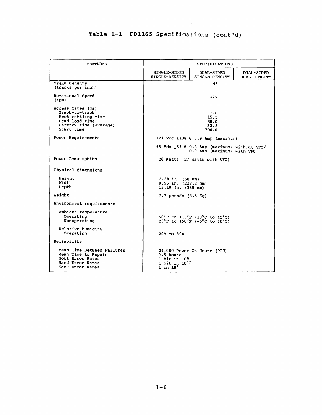
Table
1-1
FDl165
Specifications
(cont'd)
FEATURES
Track
Density
(tracks
Rotational
(rpm)
Access
Power
Power
Physical
Weight
Environment
Reliabili
per
inch)
Speed
Times (ms)
Track-to-track
Seek
settling
Head
load
Latency
Start
Requirements
Consumption
Height
Width
Depth
Ambient
Operating
Nonoperating
Relative
Operating
Mean Time
Mean TimetoRepair
Soft
Hard
Seek
time
time
time
dimensions
requirements
temperature
humidity
ty
Between
Error
Error
Error
Rates
Rates
Rates
time
(average)
Failures
SINGLE-SIDED I
SINGLE-DENSITY
+24 Vdc
+5
26
2.28
8.55
13.19
7.7
50°Fto113°F
23°Fto158°F
20%to80%
24,000
0.5
1
1
1
Vdc
Watts
pounds
hours
bit
bit
in
±10%@0.9
±5%@0.8
(27
in.
(58
in.
(217.2
in.
Power
in
109
in
1012
106
SPECIFICATIONS
DUAL-SIDED
SINGLE-DENSITY
83.3
700.0
Amp
Amp
0.9
Amp
Watts
with
rom)
mm)
(335
rom)
(3.5
Kg)
(10°C
(-5°C
On
Hours
48
360
3.0
IS
.5
30.0
(maximum)
(maximum)
(maximum)
VFO)
to
45°C)
to
70°C)
(POH)
DUAL-SIDED
I
DUAL-DENSITY
without
with
VFO
VFO/
1-6
CHAPTER 2
This
and
Disk
2.1
Before
carton
ch~pter
operating
Drive.
PRELIMINARY INSPECTION
you
for
immediately.
tiveof
aged,
'the
unpack
instructions
2.2
This
UNPACKING
section
FDl165.
INSTALLATION
gives
instructions
unpack
damage.
Do
carrier
the
(see
AND
describes
unpacking
the
If
not
disk
Section
REPACKING
Model
there
open
inspects
drive
unpacking
AND
and
for
the
2.2~1).
the
FDl165,
is
damage,
carton'
it.
by
OPERATION
installation
ModelFDl165
inspect
notify
until
If
the
following
and
repacking
the
carton
information
the
the
representa-
is
the
unpacking
the
Flexible
shipping
carr
undam-
Model
ier
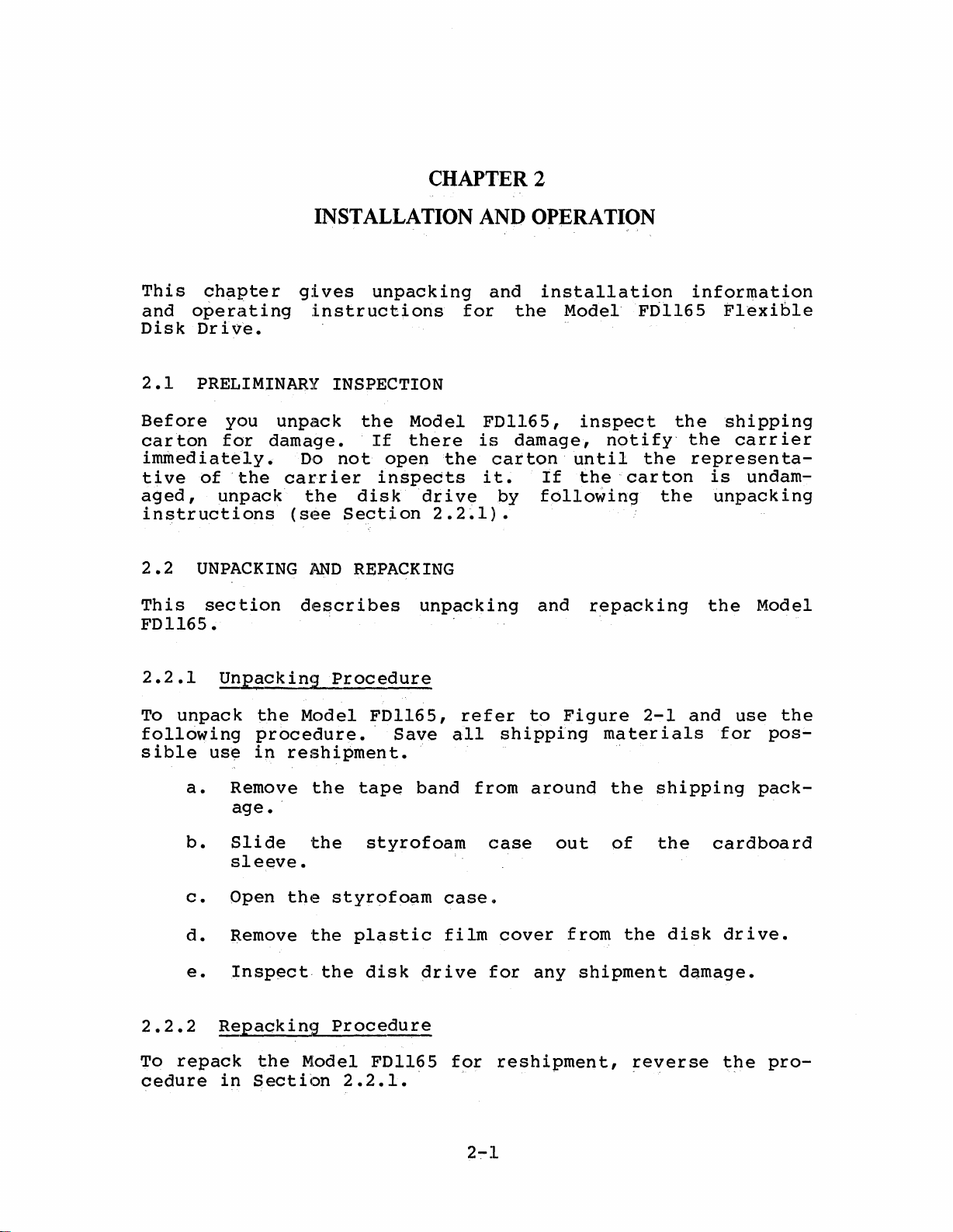
2.2.1
To
unpack
following
sible
a.
b.
c.
d.
e.
2.2.2
To
repack
cedure
Unpacking
the
procedure.'
use
in
Remove
age.
Slide
sleeve.
Open
Remove
Insp~ct,
Repacking
the
in
Section
Procedure
Model
reshipment.
the
tape
'
the
the
styrofo~m
the
plastic
the
Procedure
Model
2.2.1.
FDl165,
Save
band
styrofoam
disk
drive
FDl165
refer
all
case.
film
for
to
shipping
from
around
case
cover
for
any
reshipment,
Figure
out
from
shipment
rna
.
the
of
2-1
ter
ialsfor
shipping
the
the
reverse
and
cardboard
disk
damage.
use
pack-
drive.
t~e
the
pos-
pro-
PLASTIC
FILM
COVER
Figure
2-1
Unpacking
2-2
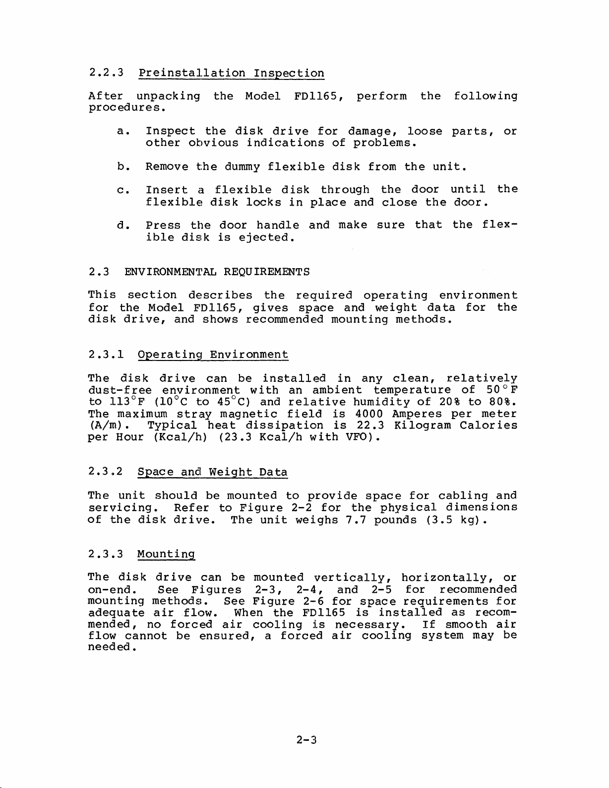
2.2~3
Preinstallation
Inspection
After
unpacking
procedures.
a.
b.
c.
a.
2.3
This
for
disk
2.3.1
The
dust-free
to
The
(Aim)
per
ENVIRONMENTAL
section
the
drive,
Operatinq
disk
113°F
maximum
•
Hour
Inspect
other
Remove
Insert
flexible
Press
ible
disk
Model
and
drive
environment
(10°C
stray
Typical
(Kcal/h)
the
the
obvious
the
dummy
a
flexible
disk
the
door
is
REQUIREMENTS
descr
ibes
FDl165,
shows
Environment
can
to
45°C)
magnetic
hea
(23.3
Model
dis
k
drive
indications
flexible
locks
handle
ejected.
the
gi
ves
recommended
be
installed
with
and
t
diss
ipation
Kcal/h
FDl165,
disk
in
required
space
an
relative
field
for
of
disk
through
place
and
mounting
in
ambient
is
is
with
perform
damage,
problems.
and
make
opera
and
any
humidity
4000
22.3
VFO).
loose
from
the
the
door
close
sure
that
ting
weight
methods.
clean,
temperature
of
Amperes
Ki
logram
the
following
parts,
unit.
until
the
door.
the
environment
da
ta
rela
20%
per
for
tively
of
to
Calor
the
flex-
the
50
° F
80%.
meter
ies
or
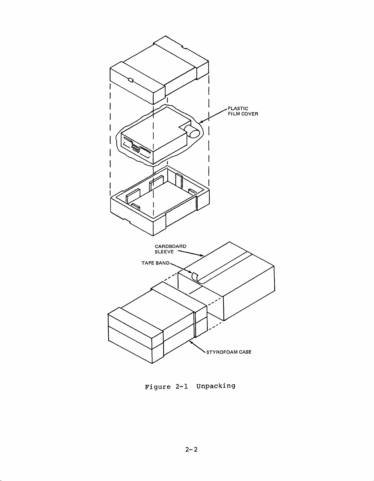
2.3.2
The
unit
servicing.
of
the
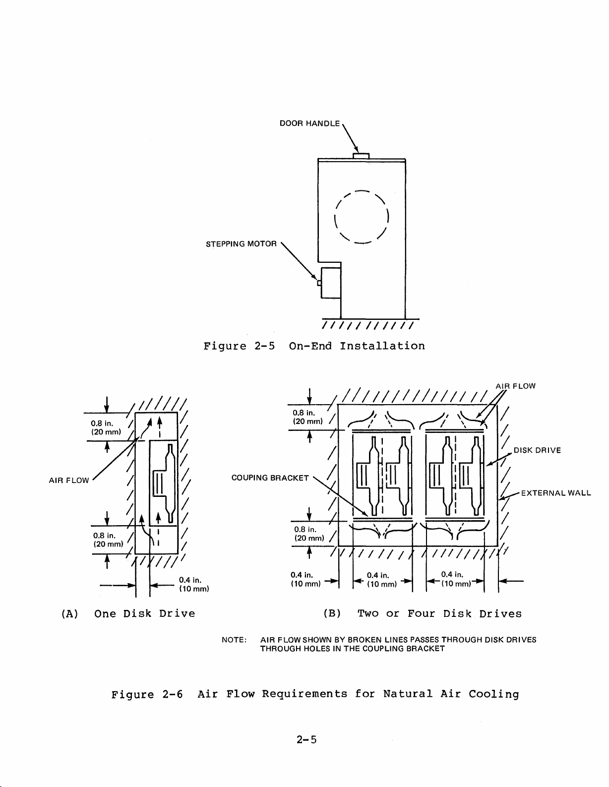
2.3.3
The
disk
on-end.
mounting
adequate
mended,
flow
cannot
needed.
Space
should
Refer
disk
drive.
Mounting
drive
See
methods.
airflow.
no
forced
be
and
can
Figures
ensured,
Weight
be
mounted
to
The
be
See
air
Figure
mounted
Figure
When
cooling
Data
unit
2-3,
a
to
the
forced
provide
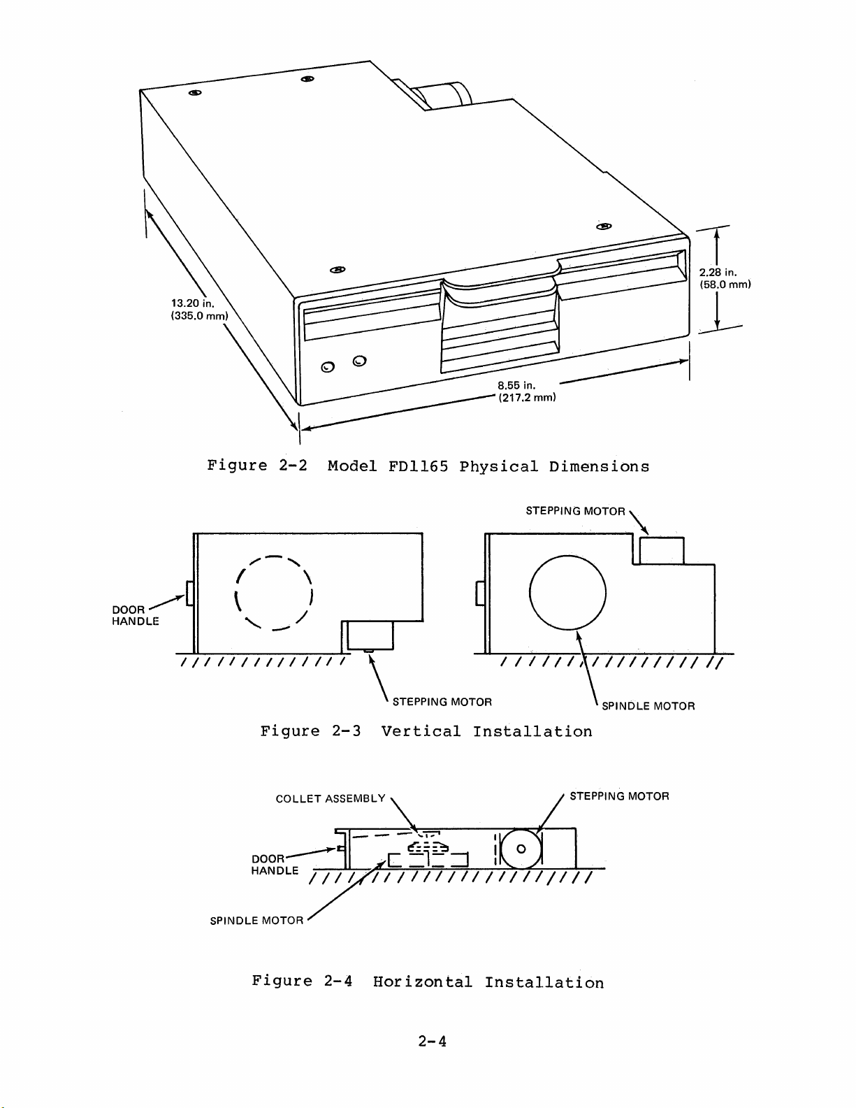
2-2
weighs
vertically,
2-4,
2-6
FDl165
is
2-3
for
the
7.7
and
for
necessary.
air
space
pounds
2-5
space
is
installed
cooling
for
physical
horizontally,
for
requirements
cabling
dimensions
(3.5
kg).
recommended
as
If
smooth
system
and
for
recom-
air
may
or
be
Figure
{ \
/-,
2-2
Model
FDl165
Physical
Dimensions
DOOR~
HANDLE
///1/1//1111//
\ J
'-
--/
Figure
COLLET
SPINDLE MOTOR
Figure
\
2-3
ASSEMBLY
2-4
111/11,1//////////
STEPPING MOTOR SPINDLE MOTOR
Vertical
Horizontal
Installation
STEPPING MOTOR
Installation
2-4
DOOR
HANDLE
AIR
~///I//
0.8. in.
(20mm)
FLOW
_L---+-+--\o
~f
0.8
(20mm)
/!
-~/
'-~_I
in. I I /
///:'41n.
-----i
+
I
I /
STEPPING MOTOR
Figure
II
/
'!
/
/
(10 mm)
2-5
COUPING
~
On-End
BRACKET
0.8
(20mm)
0.4
(10 mm)
/ / / / / /
Installation
in. /
i.~.
7~1/
II
-I:------+~--f__
---I
/ / /
(A)
One
Disk
Figure
Drive
2-6
Air
NOTE:
Flow
(B)
AIR
FLOW SHOWNBYBROKEN LINES
THROUGH HOLES IN THE COUPLING
Requirements
2-5
Two
for
or
Natural
Four
PASSES
BRACKET
Disk
THROUGH DISK DRIVES
Air
Drives
Cooling
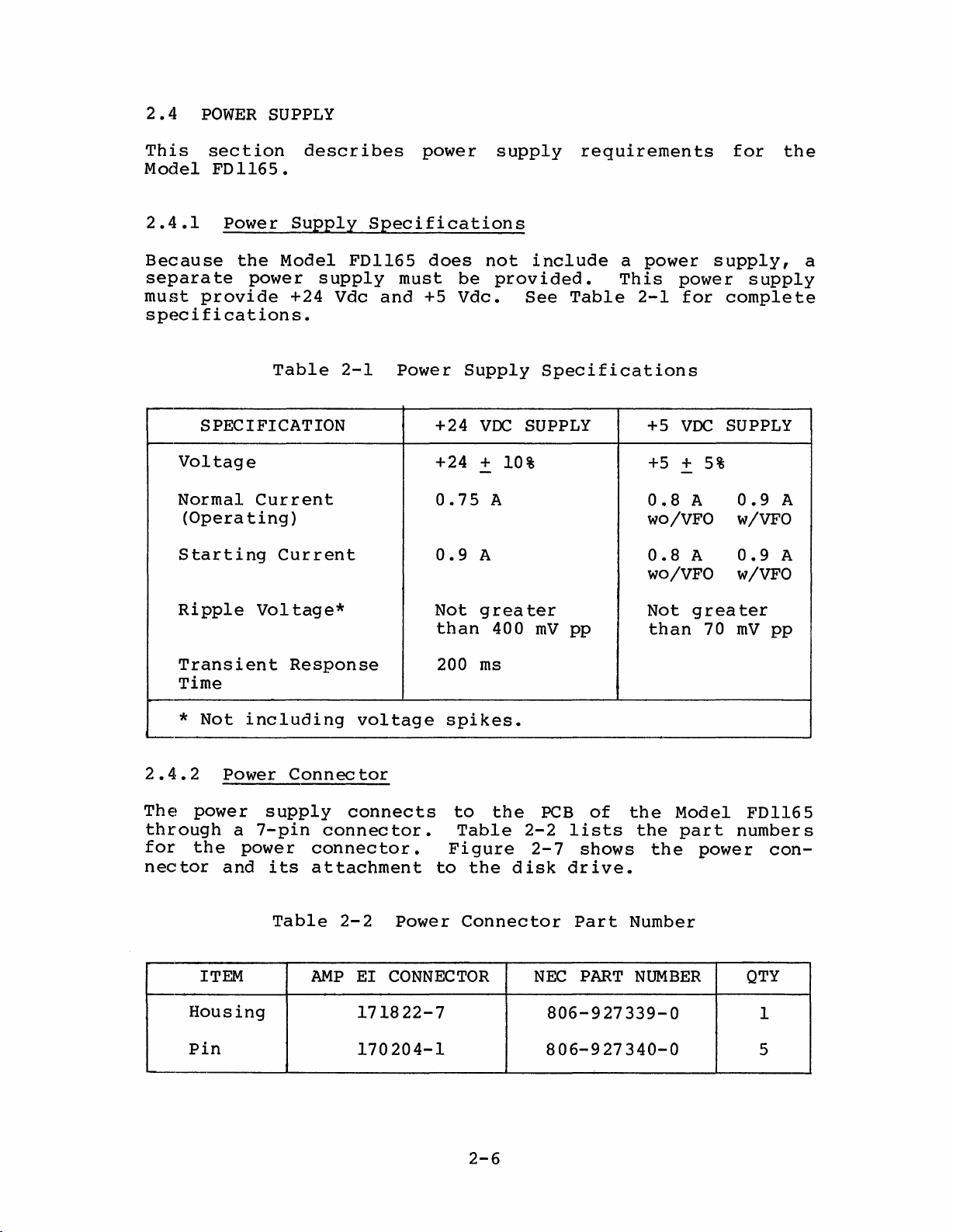
2.4
POWER
SUPPLY
This
Model
2.4.1
Because
separate
must
specifications.
section
FDl165.
Power
the
power
provide
SPECIFICATION
Voltage
Normal
(Opera
Starting
ting)
describes
Supply
Model
+24
Table
Current
Current
FDl165
supply
Vdc
2-1
power
Specifications
does
must
and
Power
+5
+24
+24
0.75
0.9
be
Vdc.
Supply
supply
not
VDC
+
-
A
include
provided.
See
Specifications
SUPPLY +5
10%
A
requirements
a
power
This
Table
2-1
+5
0.8
wO/VFO w/VFO
0.8
wO/VFO
supply,
power
for
VDC
+
5%
-
A
A
for
complete
SUPPLY
0.9
0.9
w/VFO
the
supply
A
A
a
Ripple
Transient
Time
*
2.4.2
The
through
for
nector
Housing
Pin
Not
Power
power
the
and
ITEM
Vol
including
supply
a
7-pin
power
its
Table
tage*
Response
voltage
Connector
connects
connector.
connector.
attachment
2-2
AMP
EI
171822-7
170204-1
Not
greater
than
200
ms
spikes.
to
Table
Figure
to
the
Power
CONNECTOR
Connector
400
the
mV
pp
PCB
2-2
lists
2-7
disk
drive.
Part
NEC
806-927339-0
806-927340-0
of
shows
PART
Not
than
the
Model
the
part
the
Number
NUMBER
greater
70
mV
numbers
power
pp
FDl165
con-
QTY
1
5
2-6

POWER
CONNECTOR --.......
!PCB
....
2.4.3
The
Figure
pin
DC
POWER
SUPPLY
Figure
Power
Connector
assignments
2-8.
SIGNAL
+24
GROUND
+5VDC
GROUND
FG
VDC
NAME
2-7
for
Power
Pin
Assignments
the
Connector
power
Location
connector
PIN
are
NUMBER
1
2
3
4
5
6
7
shown
POWER
CONNECTOR
in
Figure
2-8
Pin
and
Line
Assignments
Connector
2-7
for
the
Power
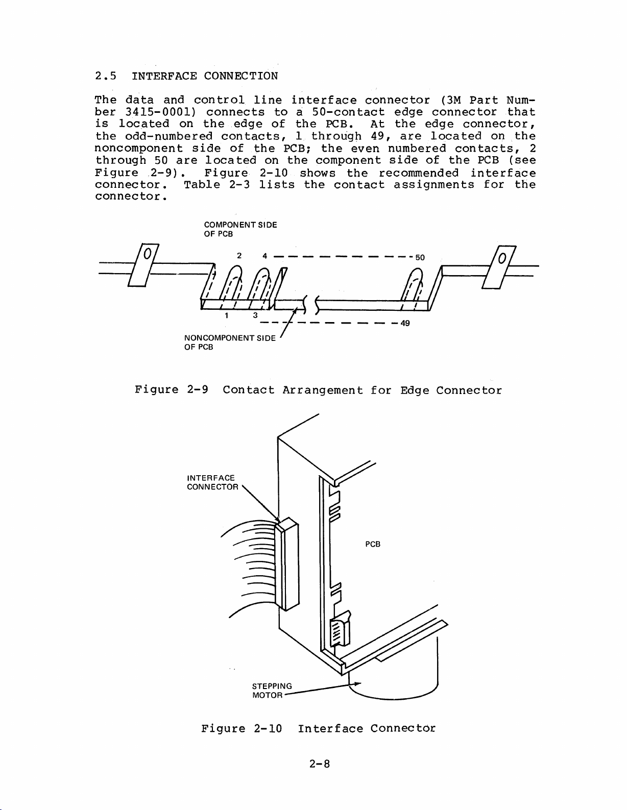
2.5
INTERFACE
CONNECTION
The
data
ber
3415-0001)
is
loca
the
odd-numbered
and
ted
noncomponent
through
Figure
50
.2-9).
connector.
connector.
Figure
control
connects
on
the
edge
contacts,
side
are
of
located
Figure
Table
NONCOMPONENT SIDE
OF
PCB
2-9
2-3
COMPONENT SIDE
OF
PCB
24----------50
Contact
line
to
of
the
PCB;
on
the
2-10
lists
Arrangement
interface
~
50-contact
the
PCB.
1
through
the
component
shows
the
even
the
contact
- - -
connector
edge
At
the
49,
are
numbered
side
recommended
assignments
-49
for
Edge
(3M
connector
edge
connector,
located
contacts,
of
the
Connector
Part
Num-
that
on
PCB
interface
for
the
2
(see
the
INTERFACE
CONNECTOR
Figure
2-10
Interface
2-8
PCB
Connector
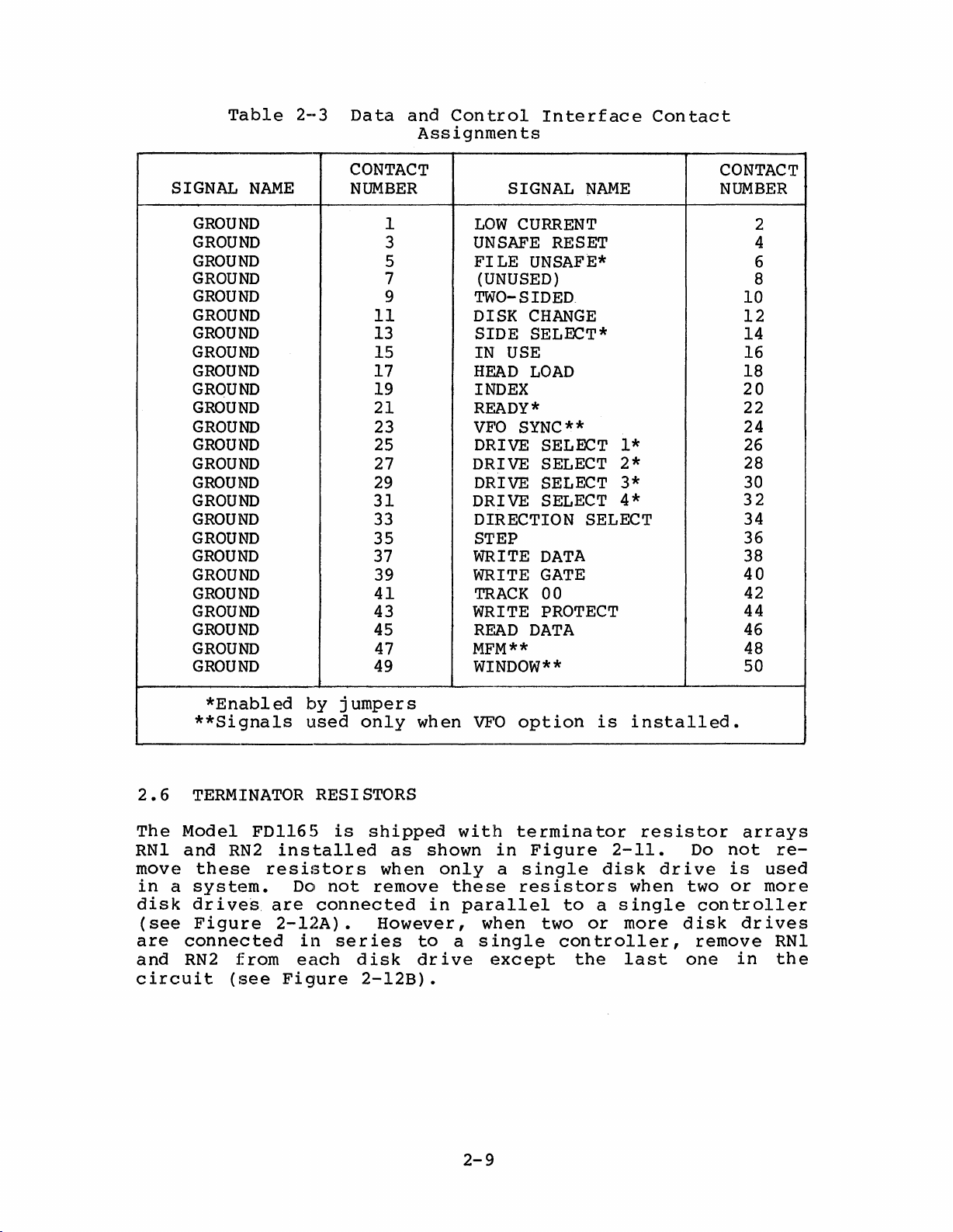
Table
2-3
Data
and
Control
Assignments
Interface
Contact
SIGNAL
GROUND
GROUND
GROUND
GROUND
GROUND
GROUND
GROUND
GROUND
GROUND
GROUND
GROUND
GROUND
GROUND
GROUND
GROUND
GROUND
GROUND
GROUND
GROUND
GROUND
GROUND
GROUND
GROUND
GROUND
GROUND
NAME
CONTACT
NUMBER
1
3
5
7
9
11
13
15
17
19
21
23
25
27
29
31
33
35
37
39
41
43
45
47
49
SIGNAL
LOW
CURRENT
UNSAFE
FILE
UNSAFE*
NAME
RESET
(UNUSED)
TWO-SIDED
DISK
SIDE
CHANGE
SELECT*
IN USE
HEAD
LOAD
INDEX
READY
VFO
DRIVE SELECT
DRIVE SELECT
*
SYNC**
1*
2*
DRIVE SELECT 3*
DRIVE SELECT
4*
DIRECTION SELECT
STEP
WRITE
WRITE
TRACK
DATA
GATE
00
WRITE PROTECT
READ
DATA
MFM**
WINDOW**
CONTACT
NUMBER
2
4
6
8
10
12
14
16
18
20
22
24
26
28
30
32
34
36
38
40
42
44
46
48
50
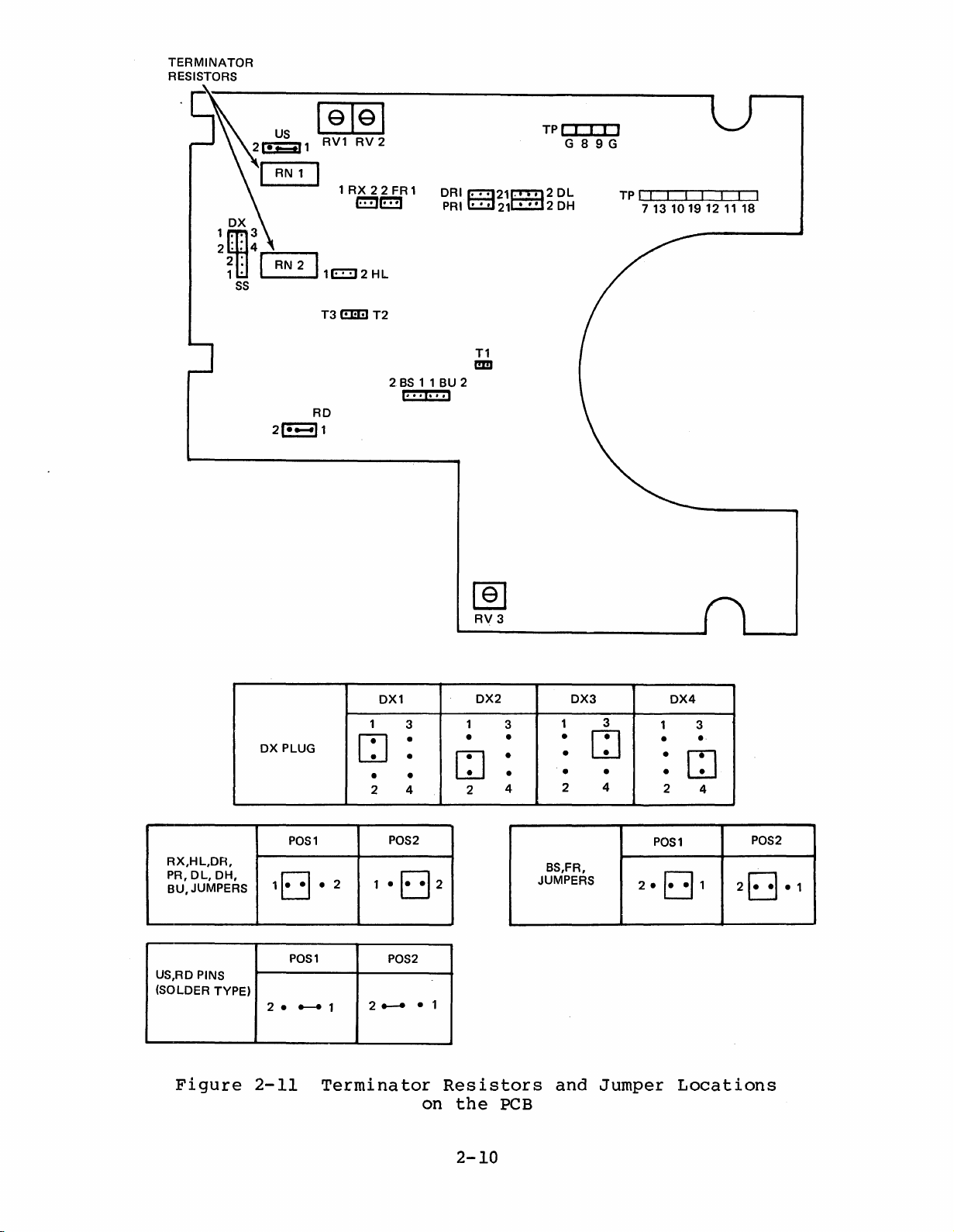
2.6
The
RNI
move
in
a
disk
(see
are
and
circuit
*Enabled
**Signals
TERMINATOR
Model
and
these
FDl165
RN2
resistors
system.
drive~
are
Figure
connected
RN2
from
(see
by
used
RESISTORS
installed
Do
not
connected
2-12A).
in
each
Figure
jumpers
only
is
shipped
when
remove
However,
ser
ies
disk
2-12B).
as
when
shown
only
in
to
dr
ive
VFO
with
these
parallel
when
a
single
except
option
terminator
in
Figure
a
single
resistors
two
to
con
is
a
or
troller,
the
installed.
2-11.
disk
when
single
more
last
resistor
drive
disk
one
arrays
Do
not
is
two
or
controller
drives
remove
in
re-
used
more
RNI
the
2-9
TERMINATOR
RESISTORS
~
RV1
RV
2
1
RX22FR 1 DRI
I:!!J~
2 I
RN
__
---I
1E::!J 2 Hl
T3
(!E!I
T2
2BS1 1 BU 2
~21C!!!l2
PRIE::il21o:::::J
T1
I!ID
TPI I I I I
G89G
DL
2 0 H
TP I I I I I
7 13
10191211
I I I
18
RX,HL,DR,
PR,
DL,
BU,JUMPERS
US,RD PINS
(SOLDER TYPE)
DH,
OX PLUG
POS1
1Ej
POS1
2.
~
[§]
RV
3
2
DX2
1
•
CJ
3
•
•
•
4
DX1
1
3
•
~
2
•
1
•
•
•
2 4 2
POS2
1 •
Ej
POS2
2~
• 1
DX3
3
1
•
CJ
•
• • •
4
2
BS,FR,
JUMPERS
2.
DX4
1 3
•
•
2
POS1
E3
•
CJ
4
1
2Ej
POS2
.1
Figure
2-11
Terminator
Resistors
on
the
2-10
PCB
and
Jumper
Locations
 Loading...