

Page 1

SERVER ES1400
()
■■■■■■■
■■■■■■■
■■■■■■■
■■■■■■■
■■■■■■■
■■■■■■■
User's Guide
■■■■■■■
■■■■■■■
■■■■■■■
■■■■■■■
■■■■■■■
■■■■■■■
■■■■■■■
■■■■■■■
Page 2

xxx
Page 3

SERVER ES1400
()
■■■■■■■
■■■■■■■
■■■■■■■
■■■■■■■
■■■■■■■
■■■■■■■
User's Guide
■■■■■■■
■■■■■■■
■■■■■■■
■■■■■■■
■■■■■■■
■■■■■■■
■■■■■■■
■■■■■■■
Page 4

Proprietary Notice and Liability Disclaimer
The information disclosed in this document, including all designs and related materials, is
the valuable property of NEC Computer Systems Division (hereinafter "NEC CSD") and/or
its licensors. NEC CSD and/or its licensors, as appropriate, reserve all patent, copyright and
other proprietary rights to this document, including all design, manufacturing, reproduction,
use, and sales rights thereto, except to the extent said rights are expressly granted to others.
The NEC CSD product(s) discussed in this document are warranted in accordance with the
terms of the Warranty Statement accompanying each product. However, actual
performance of each such product is dependent upon factors such as system configuration,
customer data, and operator control. Since implementation by customers of each product
may vary, the suitability of specific product configurations and applications must be
determined by the customer and is not warranted by NEC CSD.
To allow for design and specification improvements, the information in this document is
subject to change at any time, without notice. Reproduction of this document or portions
thereof without prior written approval of NEC CSD is prohibited.
Trademarks
INTEL is a registered trademark of Intel Corporation.
MS-DOS is a registered trademark of Microsoft Corporation.
Pentium is a registered trademark of Intel Corporation.
All other product, brand, or trade names used in this publication are the trademarks or registered
trademarks of their respective trademark owners.
PN: 904485-02
Copyright 1999
NEC Computer Systems Division
All Rights Reserved
Page 5

Contents
Using This Guide ............................................................... vii
Text Conventions ......................................................................................... viii
Related Documents ....................................................................................... ix
Safety Notices ................................................................................................. x
Safety Notices for Users Outside of the U.S.A. and Canada ................... xi
Care and Handling ....................................................................................... xii
System Overview..............................................................1-1
Overview......................................................................................................1-2
System Chassis ...........................................................................................1-4
Power Supply............................................................................................... 1-5
Peripheral Bays ...........................................................................................1-5
System Board Features................................................................................ 1-6
Pentium II Processor ...........................................................................1-7
System Memory...................................................................................1-7
I/O Expansion Slots ............................................................................1-7
Real-Time Clock/Calendar ..................................................................1-8
BIOS ...................................................................................................1-8
IDE Controller .....................................................................................1-8
SCSI Controller ...................................................................................1-8
Network Controller .............................................................................. 1-9
Video Controller ................................................................................1-10
Peripheral Controller .........................................................................1-10
Serial Ports .......................................................................1-10
Parallel Port ......................................................................1-10
External Device Connectors...............................................................1-10
System Board Management Controller (BMC) .................................... 1-11
System Security.........................................................................................1-11
Security with Mechanical Locks and Monitoring................................1-11
Software Locks via the System Setup Utility......................................1-12
Setting Up Your System .................................................2-1
Selecting a Site ............................................................................................2-2
Unpacking the System .................................................................................2-3
Getting Familiar with the System ................................................................2-3
Front View...........................................................................................2-4
Rear View ............................................................................................2-5
Making Connections ....................................................................................2-6
Setting the Line Voltage ............................................................................... 2-8
Connecting the Power Cord .......................................................................2-10
Powering On Your System .........................................................................2-11
Configuring Your System ...............................................3-1
Configuring Your System.............................................................................3-2
BIOS Setup Utility .......................................................................................3-3
Using the BIOS Setup Utility ...............................................................3-3
Contents iii
Page 6

BIOS Setup Configuration Settings ..................................................... 3-4
Main Menu ......................................................................................... 3-5
Primary/Secondary IDE Master and Slave Submenu...........3-6
Keyboard Submenu .............................................................3-7
Processor Settings Submenu ...............................................3-7
Advanced Menu .................................................................................. 3-8
PCI Configuration Submenus ..............................................3-8
PCI Device, Slot 1 - Slot 4 Submenus ..................................3-9
Integrated Peripheral Configuration Submenu...................3-10
Advanced Chipset Control .................................................3-11
Security Menu .................................................................................. 3-11
Security menu (Continued) ............................................................... 3-12
Server Menu ..................................................................................... 3-13
System Management Submenu .........................................3-14
Server Management Information Submenu........................3-15
Console Redirection Submenu...........................................3-15
Boot Menu ........................................................................................ 3-16
Boot Device Priority Submenu ...........................................3-16
Hard Drive Submenu.........................................................3-17
Removable Devices ............................................................3-17
Exit Menu ......................................................................................... 3-18
Symbios Configuration Utility ................................................................... 3-19
Running the Symbios Configuration Utility ....................................... 3-19
Changing the Adapter and Device Configurations ............................. 3-20
Optional RAID Controller .......................................................................... 3-22
Factory Installed Controller .............................................................. 3-22
Add-on Controller ............................................................................. 3-23
DACCF Configuration Utility............................................................. 3-23
Configuring System Board Jumpers.......................................................... 3-24
Before You Begin .............................................................................. 3-24
Moving System Board Jumpers ........................................................ 3-26
Resetting the CMOS NVRAM ............................................................. 3-27
Clearing and Changing the Passwords .............................................. 3-27
Recovering the BIOS ......................................................................... 3-28
Boot Block Write Protect ................................................................... 3-28
BMC Forced Update Mode ................................................................ 3-28
Upgrading Your System.................................................. 4-1
Static Precautions ....................................................................................... 4-2
Preparing Your System for Upgrade ............................................................ 4-3
Equipment Log............................................................................................ 4-3
Removing a Side Panel ................................................................................ 4-4
Installing a Side Panel................................................................................. 4-5
Modifying the System Board........................................................................ 4-6
Replacing the Real-time Clock Battery ........................................................ 4-6
Replacing the Pentium II Processor ............................................................. 4-8
Replacing the SECC Version ............................................................... 4-9
Replacing the SEPP Version.............................................................. 4-11
Replacing the SECC2 Version ........................................................... 4-13
DIMMs ...................................................................................................... 4-15
Memory DIMM Configurations .......................................................... 4-16
Installing DIMMs .............................................................................. 4-17
iv Contents
Page 7

Removing DIMMs ..............................................................................4-18
Option Boards ...........................................................................................4-19
Installation Considerations ...............................................................4-19
Controller/Adapter Hardware Configurations ....................................4-20
Installing an Option Board ................................................................4-20
Removing an Option Board................................................................4-23
Hard Disk Drives .......................................................................................4-24
Installing an Internal Hard Disk Drive...............................................4-26
Removing an Internal Hard Disk Drive .............................................. 4-28
Front Panel................................................................................................4-29
Removing the Front Panel .................................................................4-29
Installing the Front Panel ..................................................................4-30
Removing EMI Shields and Filler Panels ....................................................4-31
Removable Media Devices .......................................................................... 4-32
Installing a 5.25-Inch Device ............................................................. 4-33
Removing a 5.25-Inch Device ............................................................4-35
Problem Solving................................................................5-1
Static Precautions .......................................................................................5-2
Troubleshooting Checklists..........................................................................5-3
Initial System Startup .........................................................................5-3
Running New Application Software......................................................5-4
After System Has Been Running Correctly...........................................5-5
Additional Troubleshooting Procedures........................................................5-6
Preparing the System for Diagnostic Testing........................................5-6
Monitoring POST .................................................................................5-7
Verifying Proper Operation of Key System Indicators ........................... 5-8
Confirming Loading of the Operating System.......................................5-8
Specific Problems and Corrective Actions ....................................................5-9
Power LED Does Not Light...................................................................5-9
Incorrect or No Beep Code.................................................................5-10
No Characters Appear on Screen ....................................................... 5-10
Characters are Distorted or Incorrect ................................................5-11
System Cooling Fan Does Not Rotate.................................................5-11
Diskette Drive Activity LED Does Not Light .......................................5-12
Hard Disk Drive Activity LED Does Not Light ....................................5-12
CD-ROM Drive Activity Light Does Not Light .....................................5-13
Problems with Application Software ..................................................5-13
Press F2 Key to Enter Setup: Prompt Does Not Display .....................5-13
Enable F2 Prompt by Using SSU....................................... 5-14
Enable F2 Prompt by Changing a Jumper and Using SSU 5-15
Bootable CD-ROM Is Not Detected ....................................................5-16
Problems with the Network........................................................................ 5-16
PCI Installation Tips ..................................................................................5-17
BIOS User’s Information ............................................................................ 5-17
Error and Status Messages ...............................................................5-17
POST Error Codes and Messages....................................................... 5-20
System Cabling................................................................ A-1
Before You Begin .........................................................................................A-2
Static Precautions .......................................................................................A-2
Contents v
Page 8

Standard Configuration .............................................................................. A-3
RAID Configuration ..................................................................................... A-8
System Setup Utility...................................................... B-1
System Setup Utility (SSU).......................................................................... B-2
Creating SSU Diskettes............................................................................... B-3
Running the SSU ........................................................................................ B-4
Customizing the SSU .......................................................................... B-5
Launching a Task ...............................................................................B-6
Resource Configuration Add-in (RCA) Window .................................... B-7
Defining an ISA Card .......................................................................... B-8
Adding and Removing ISA Cards......................................................... B-8
Modifying Resources ......................................................................... B-10
Recommended Resource Settings...................................................... B-11
System Resource Usage .................................................................... B-12
Multiboot Add-in (MBA) Window .......................................................B-13
Password Administration (PWA) Window........................................... B-13
System Event Log (SEL) Window....................................................... B-14
Exiting the SSU......................................................................................... B-14
Emergency Management Port...................................... C-1
Emergency Management Port...................................................................... C-2
How the EMP Works ................................................................................... C-3
EMP Requirements and Configurations.......................................................C-5
Setting Up the Server for the EMP............................................................... C-6
System Management Submenu........................................................... C-6
Console Redirection Submenu ............................................................C-7
Main EMP Window ......................................................................................C-7
Toolbar ............................................................................................... C-7
Status Bar .......................................................................................... C-8
EMP Console Main Menu ....................................................................C-8
Server Control Operations ..................................................................C-9
Connect.............................................................................. C-9
Power On/Off ................................................................... C-10
Reset ................................................................................ C-11
Phonebook ................................................................................................ C-12
Management Plug-ins ...............................................................................C-13
SEL Viewer .......................................................................................C-13
SEL Viewer Menu Options ................................................ C-14
Sensor Type Codes ........................................................... C-15
Using the Sensor Type Code Table.................................... C-15
SDR Viewer....................................................................................... C-17
SDR Viewer Menu Options ............................................... C-18
FRU Viewer....................................................................................... C-18
FRU Viewer Menu Options ............................................... C-19
Equipment Log
Glossary
Index
vi Contents
Page 9

Using This Guide
This User’s Guide provides a quick reference to information about your system.
Its goal is to familiarize you with your system and the tasks necessary for system
configuring and upgrading.
This guide contains the following information:
Chapter 1, “System Overview” provides an overview of your system and
describes your system’s major system components. See this chapter to
familiarize yourself with your system.
Chapter 2, “Setting Up Your System” tells you how to select a site, unpack the
system, make cable connections, and power on your system.
Chapter 3, “Configuring Your System” tells you how to configure the system
and provides instructions for running the BIOS Setup Utility and the Symbios
Configuration Utility, which is used to configure SCSI devices in your system.
This chapter also provides information on system board jumper settings.
Chapter 4, “Upgrades and Options” provides you with instructions for
upgrading your system with an additional processor, optional memory, options
cards, and peripheral devices.
Chapter 5, “Problem Solving” contains helpful information for solving problems
that might occur with your system.
Appendix A, “System Cabling” includes cabling information for the onboard
SCSI controller, the onboard IDE controllers, and optional RAID controllers.
Appendix B, “System Setup Utility” provides information for configuring
onboard resources and add-in boards. It also provides information on viewing
the system event log.
Appendix C, “Emergency Management Port” provides information on a feature
that provides an interface to the Emergency Management Port (EMP) Manager.
This interface allows remote server management via a modem or direct
connection.
“Glossary” defines the standard acronyms and technical terms used in this
manual.
“Equipment Log” provides you with a sample equipment log for documenting
the system configuration and future updates you may make to your system.
Using This Guide vii
Page 10
Text Conven tions
This guide uses the following text conventions.
Warnings, cautions, and notes have the following meanings:
Warnings alert y ou to situations that could result in se rious per sonal in jury or
loss of life.
Cautions i ndi ca te situations t ha t ca n damage the system hardware or sof twa re.
!
WARNING
!
CAUTION
Note:
described.
Names of keyboard keys are printed as they appear on the keyboard. For
example,
Text or keystrokes that you enter appear as boldface type. For example, type
abc123
File names are printed in uppercase letters. For example, AUTOEXEC.BAT.
Ctrl, Alt
and press
Notes give importa nt i nf orm ation about the mater ial being
Enter
, or
ENTER
.
.
viii Using This Guide
Page 11

Related Documents
In addition to this guide, the following system documentation is included with
your server either as electronic files on E
shipped with your server.
System Release Notes
Release Notes provide you with the latest information about your system. This
information was not available at the time your user’s guide was developed.
Getting Started Sheet
The Getting Started Sheet provides several easy-to-follow steps to become
familiar with your server documentation and to complete your installation
successfully.
Network Operating System Configuration Guide
This guide contains supplemental instructions needed to install and configure
your server Windows NT v4.0, Novell NetWare v3.12, Novell NetWare v4.11,
Santa Cruz Operation (SCO) OpenServer Release 5.04 and UNIXWare 7.0
Network Operating Systems. This document is intended to complement the
more detailed procedural documents available from the vendor of the network
operating system.
XPRESSBUILDER
or as paper copy
Using This Guide ix
Page 12

Safety Notices
Caution: To reduce the risk of electric shock which could cause personal
injury, follow all safety notices. The symbols shown are used in your
documentation and on your equipment to indicate safety hazards.
Warning: Lithium batteries can be dangerous. Improper handling of lithium
batteries may result in an explosion. Dispose of lithium batteries as required
by local ordinance or as normal waste if no local ordinance exists.
Warning: The detachable power supply cord is intended to serve as the
disconnect device.
Warning: This equipment has a 3-wire, grounded power cord. To prevent
electrical hazards, do not remove or defeat the ground prong on the power
cord. Replace the power cord if it gets damaged. Contact your dealer for an
exact replacement.
Warning: The DC push-button on/off switch on the front panel does not turn
off the system AC power. Also, +5vdc is present on the system board whenever
the AC power cord is connected between the system and an AC outlet. Before
doing the procedures in this manual, make sure that your system is powered
off and unplug the AC power cord from the back of the chassis. Failure to
disconnect power before opening your system can result in personal injury
and equipment damage.
!
In the U.S.A. and Canada, the power cord must be a UL-listed detachable power
cord (in Canada, CSA-certified), type ST or SJT, 16 AWG, 3-conductor, provided
with a molded-on NEMA type 5-15 P plug cap at one end and a molded-on cord
connector body at the other end. The cord length must not exceed 9 feet (2.7
meters).
Outside the U.S.A. and Canada, the plug must be rated for 250 VAC, 10 amp
minimum, and must display an international agency approval marking. The cord
must be suitable for use in the end-user country. Consult your dealer or the
local electrical authorities if you are unsure of the type of power cord to use in
your country. The voltage change occurs via a switch in the power supply.
Warning: Under no circumstances should the user attempt to disassemble the
power supply. The power supply has no user-replaceable parts. Inside the
power supply are hazardous voltages that can cause serious personal injury. A
defective power supply must be returned to your dealer.
x Using This Guide
Page 13

Safety Notice s for Users Outside of the U.S.A . and Canada
PELV (Protected Extra-Low Voltage) Integrity: To ensure the extra-low
voltage integrity of the equipment, connect only equipment with mainsprotected electrically-compatible circuits to the external ports.
Remote Earths: To prevent electrical shock, connect all local (individual
office) computers and computer support equipment to the same electrical
circuit of the building wiring. If you are unsure, check the building wiring to
avoid remote earth conditions.
Earth Bonding: For safe operation, only connect the equipment to a building
supply that is in accordance with current wiring regulations in your country.
In the U.K., those regulations are the IEE.
Using This Guide xi
Page 14
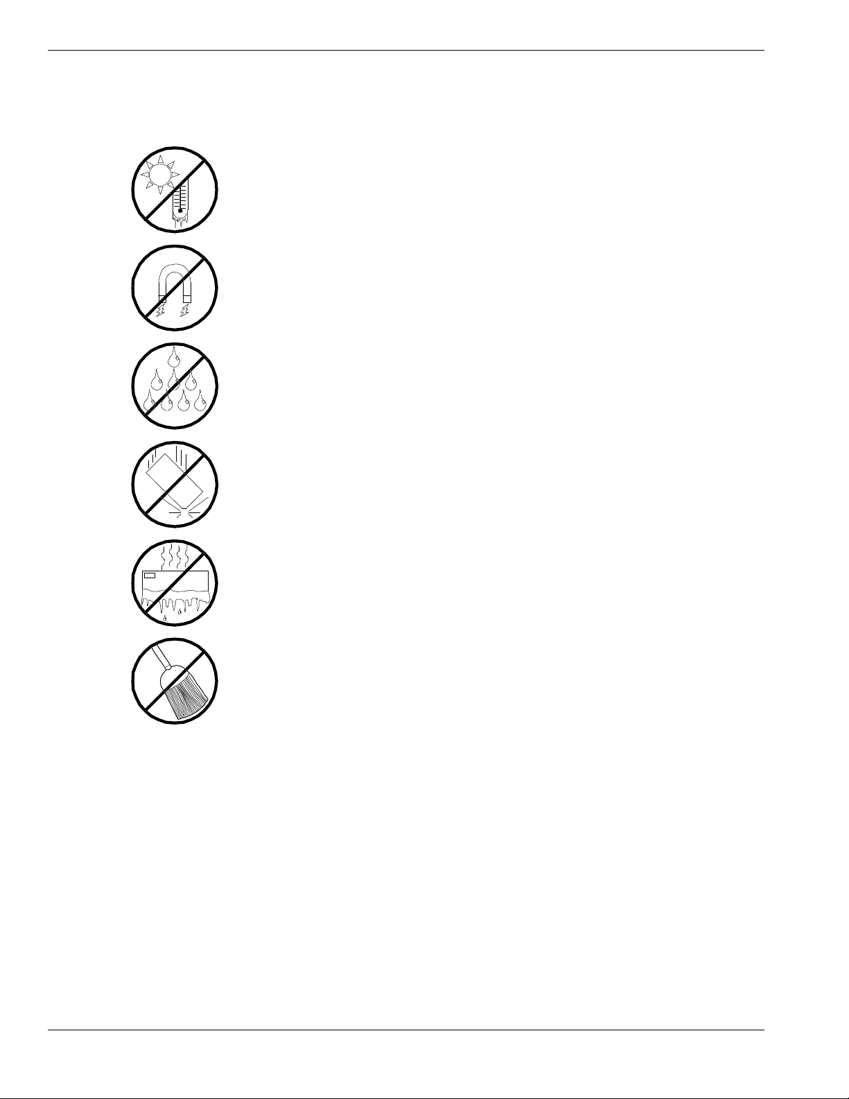
Care and Handling
Use the following guidelines to properly handle and care for your system.
Protect the system from extrem ely low or high
temperatures. Let the system wa r m (or cool)
to room t e mperature before using it.
Keep the system a way from magnetic forces.
Keep the system dry. Do not wash the
system with a wet cloth or pour fluid
into it.
Protect the system from being bumped
or dropped.
Check the system for condensation. If
condensation exists, allow it to
evaporate
before powering on the system.
Keep the system away from dust, sand,
and dirt.
xii Using This Guide
Page 15

System Overview
Overview
System Chassis
Power S up pl y
Peripheral Bays
Diskette Drive
System Board Feat ures
System Security
1
Page 16
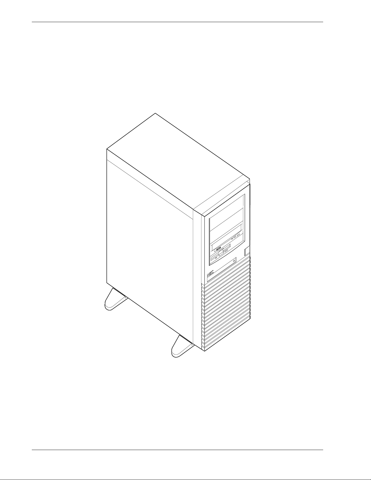
Overview
This server is a modular, multiprocessing server based on the Intel
Pentium® II chip set. The combination of compute performance,
memory capacity, and integrated I/O provides a high performance
environment for many server market applications. These range from
large corporations supporting remote offices to small companies looking
to obtain basic connectivity capability such as file and print services, email, web access, web site server, etc.
1-2 System Overview
System Front View
Page 17

As application requirements increase, you can expand your server with
additional memory, add-in boards and peripheral devices: tape devices
and hard disk drives.
Your server features the following major components:
Single high-performance Pentium II processor packaged in a Single
Edge Connector (SEC) cartridge
32 MB to 768 MB of memory, using up to three DIMMs
Four PCI expansion slots for add-in boards (one slot shared with an
ISA slot). 1x32 bit PCI bus.
Two ISA expansion slots for add-in boards (one slot shared with a PCI
slot). Embedded PC-compatible support (serial, parallel, mouse,
keyboard, diskette, and Plug and Play features).
Integrated onboard Cirrus Logic CL-GD5480 Super Video Graphics
Array (SVGA) controller with 2MB video memory.
Integrated onboard dual channel enhanced IDE controller
Integrated onboard Symbios SYM53C875 single channel SCSI
controller providing an ultra wide SCSI interface
Integrated onboard Network Interface Controller (NIC), an Intel 82558
PCI LAN controller for 10 or 100 Mbps TX Fast Ethernet networks.
RJ-45 Ethernet connector.
Integrated 1.44MB diskette drive
Four hard disk expansion bays
Three removable media expansion bays
Integrated dual Universal Serial Bus (USB) ports.
System Overview 1-3
Page 18
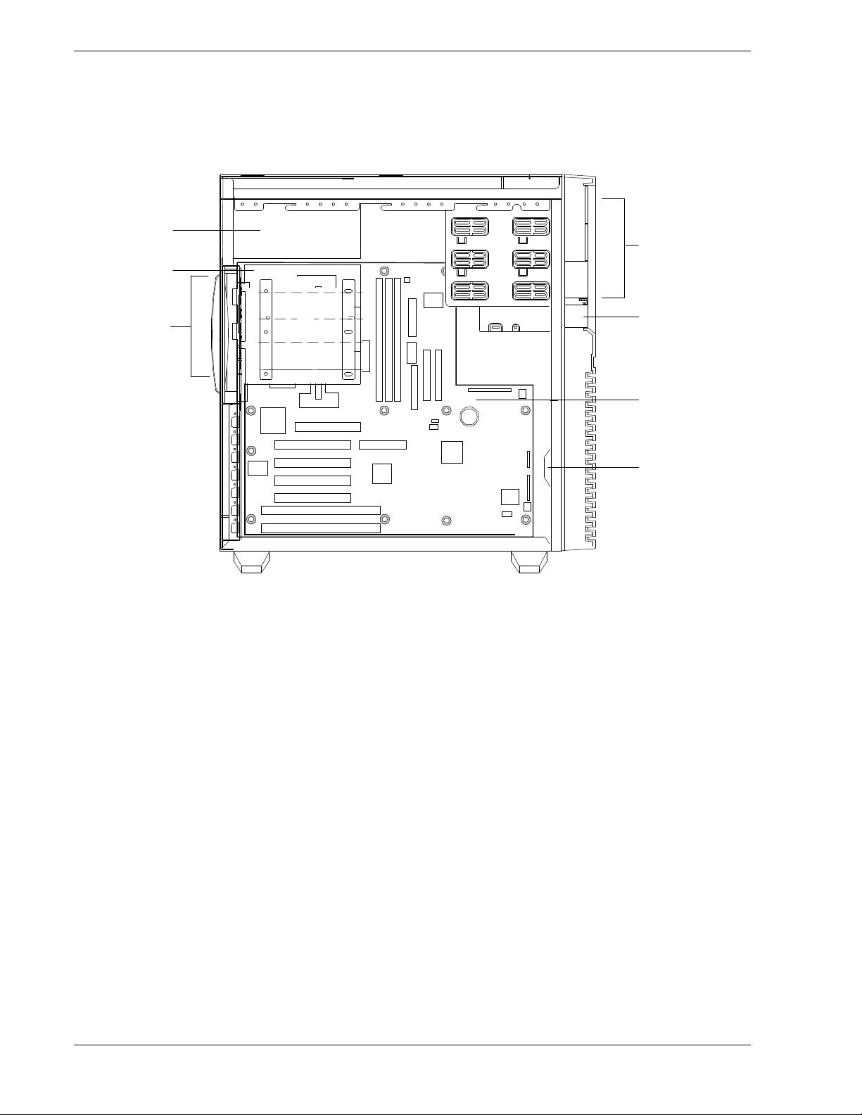
System Chassis
The system chassis is an easy-to-expand, fabricated metal structure.
The major system components are shown in this illustration.
E
A
F
G
1
2
3
4
A. Removable Media Ba ys (3)
B. 1.44 MB 3.5" diskette drive
C. System Board
B
C
D
D. Speaker
E. Power supply
F. Disk Driv e B ays (4)
G. Fan (behind disk drive bays )
1-4 System Overview
System Chassis
Page 19

Power Supply
The 260 watt power supply is switch-selectable for 115 or 230 Vac at an
operating frequency of 50/60 Hz. It is designed to comply with existing
emissions standards and provides sufficient power for a fully loaded
system configuration. The power supply voltage selection switch is
factory set to 115Vac for systems used in the United States; it is set to
230Vac for systems used in Europe.
Peripheral Ba ys
The system supports a variety of standard PC AT-compatible peripheral
devices. The chassis includes these peripheral bays:
A 3.5-inch front panel bay for mounting the standard 3.5" diskette
drive (supports 720 KB and 1.44 MB diskette media)
Three 5.25-inch removable media front panel bays for mounting half-
height 5.25-inch peripheral devices: standard CD ROM drive and
optional tape drives (not a hard disk drive)
Four internal hard disk drive bays for mounting up to four hard disk
drives.
System Overview 1-5
Page 20
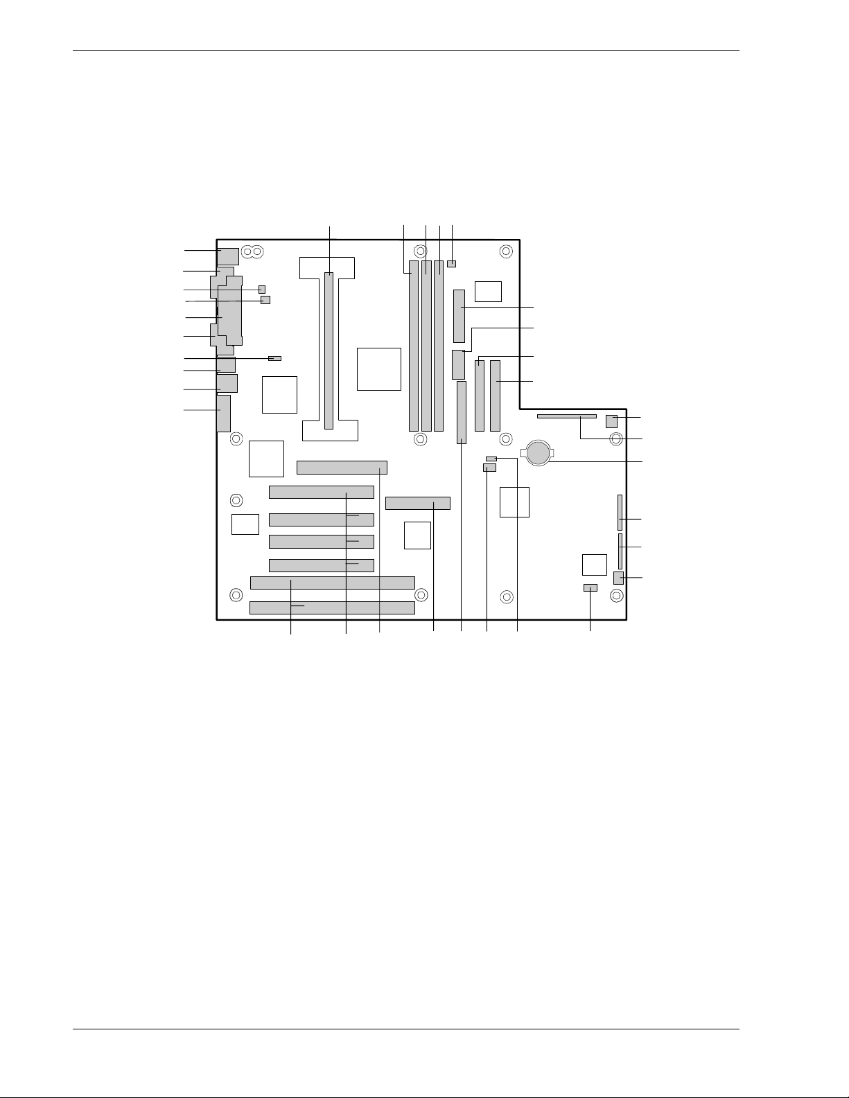
System Board Features
The system board offers a “flat” design with the processor and memory
subsystems residing on the board. This figure shows the major
components on the system board. The following subsections describe
the system board major components.
GG
FF
EE
DD
CC
BB
AA
Y
X
A
BCDE
F
G
H
Z
I
J
K
L
M
N
O
VW
A. Processor connector R. Reserved
B. DIMM slot 3 S. Diskette drive connector
C. D I MM slot 2 T. Wide SCSI connector
D. DIMM slo t 1 U. Reserved
E. Reserved V. PCI slots f or add in boards
F. ATX power connecto r W. ISA slots for add in boa rds
G. Reser ve d X. VGA monitor po rt
H. Second ar y IDE conn ect or Y. USB connect o rs
I. Primary IDE connector Z. RJ-45 network connector
J. System fan connector AA. WOL ena ble jumper (not used)
K. AT front pan el conn ect o r BB. Serial port 2 conne ct or
L. Lithium bac ku p bat t er y CC. Paral le l po rt connect or
M. Configuration jumper block DD. Fan connector (not used)
N. Configuration jumper block EE. Chassis intrusion connector
O. Syste m fan conn ect or (no t us ed) FF. Serial port 1 conne ct or
P. Reserved GG. Keyboard and Mouse connectors
Q. Reserved
1-6 System Overview
U
System Board
T
PQRS
Page 21

Pentium II Processor
The system board includes a Pentium II processor packaged in a Single
Edge Contact (S.E.C.) cartridge. The cartridge includes the processor
core with an integrated 16 KB primary (L1) cache; the secondary (L2)
cache; a thermal plate; and a back cover. The processor implements the
MMX™ technology and the processor’s numeric coprocessor significantly
increases the speed of floating-point operations.
The processor external interface operates at 100 MHz. The second-level
cache is located on the substrate of the S.E.C. cartridge. The cache
includes burst pipelined synchronous static RAM (BSRAM). The L2
cache is offered in 512 KB configurations only, with error correcting
code (ECC) that operates at half the core clock rate.
System Memory
The system board contains three 168-pin DIMM sockets. Memory is
partitioned as three banks of SDRAM DIMMs, each providing 72 bits of
noninterleaved memory (64-bit main memory plus ECC). Your system
may include from 32 MB to 768 MB of memory, using up to four
DIMMs.
System memory begins at address 0 and is continuous (flat addressing)
up to the maximum amount of DRAM installed (exception: system
memory is noncontiguous in the ranges defined as memory holes using
configuration registers). The system supports both base (conventional)
and extended memory.
I/O Expansion Slots
The server's expansion capabilities meet the needs of file and
application servers for high performance I/O by providing a
combination of PCI local bus and ISA connectors.
The system board has two full-length ISA bus connectors. One of the
connectors shares a chassis expansion slot with a PCI connector. ISA
features:
Bus speed up to 8.33 MHz
16-bit memory addressing
8- or 16-bit data transfers
Plug and Play ready.
System Overview 1-7
Page 22

The system board has four full-length PCI connectors. One of the
connectors shares a chassis expansion slot with an ISA connector. PCI
features:
Bus speed up to 33 MHz
32-bit memory addressing
5 V signaling environment
Burst transfers of up to 133 Mbps
8-, 16-, or 32-bit data transfers
Plug and Play ready
Parity enabled.
Real-Time Clock/Calendar
The real-time clock provides system clock/calendar information stored
in a non-volatile memory (NVRAM). The real-time clock battery provides
power backup for the real-time clock.
BIOS
A BIOS and Setup Utility are located in the Flash EPROM on the system
board and include support for system setup and PCI/ISA Plug-and-Play
auto-configuration. A number of security, reliability, and management
features also have been incorporated to meet vital server needs.
IDE Controller
The system includes a dual channel enhanced IDE interface controller.
The controller has a primary and secondary connector located on the
system board, each connector supporting a master and a slave device.
The IDE controller provides support for the internally mounted
standard CD-ROM, an optional tape drive, and up to three optional
hard disk drives for a total of four IDE devices.
SCSI Controller
The system includes a Symbios Logic SYM53C875 single channel PCI
SCSI controller. The controller is capable of operations using either 8 or
16 bit SCSI providing 10 MB/s (Fast-10) or 20 MB/s (Fast-20)
throughput, or 20 MB/s (Ultra) or 40 MB/s (Ultra-wide). As
implemented, the controller attaches to a 68 pin 16 bit (wide) SCSI
connector interface. As a PCI bus master the SYM53C875 supports
burst data transfers on PCI up to the maximum rate of 132 MB/sec
using onchip buffers.
1-8 System Overview
Page 23

The SCSI controller provides support for optional SCSI devices
including internally mounted tape and/or up to four internally mounted
hard disk drives. No logic, termination, or resistor loads are required to
connect devices to the SCSI controller other than termination at the end
of the cable. The SCSI bus is terminated on the system board with
active terminators that cannot be disabled.
Network Controller
The system board includes a 10BASE-T/100BASE-TX network
controller based on the Intel 82558 Fast Ethernet PCI Bus Controller.
As a PCI bus master, the controller can burst data at up to
132 MB/sec. The controller contains two receive and transmit FIFO
buffers that prevent data overruns or underruns while waiting for
access to the PCI bus. The controller has the following:
32-bit PCI bus master interface (direct drive of bus), compatible with
PCI Bus Specification, Revision 2.1
Chained memory structure with improved dynamic transmit chaining
for enhanced performance
Programmable transmit threshold for improved bus utilization
Early receive interrupt for concurrent processing of receive data
On-chip counters for network management
Autodetect and autoswitching for 10 or 100 Mbps network speeds
Support for both 10 Mbps and 100 Mbps networks, capable of full or
half duplex, with back-to-back transmit at 100 Mbps.
The network status LEDs on the system board indicate:
Transmit/receive activity on the LAN
Valid link to the LAN
10/100 Mbps transfer mode.
System Overview 1-9
Page 24

Video Controller
The system has a high-performance SVGA subsystem that supports the
following:
BIOS compatibility with VGA, EGA, CGA, Hercules Graphics, and
MDA
2 MB of Video Random Access Memory (VRAM) video buffer
16-bit bus for high-speed display memory access
Hardware accelerated bit block transfers (BITBLT)
Display power management system
Supports 72Hz refresh, non-interlaced at: 640x480, 800x600,
1024x768, or 1280x1024 resolutions
Displays of up to 16M colors at 640x480 and 800x600 resolutions,
64K colors at 1024x768 resolutions and 256 colors at 1280x1024
resolutions.
Periph eral Controller
The advanced integrated peripheral controller supports two serial ports,
one parallel port, diskette drive, PS/2-compatible keyboard and mouse,
and integrated Real Time Clock (RTC). The system provides the
connector interface for each port.
Serial Ports
Both serial ports are relocatable. Each serial port can be set to one of
four different COM ports and can be enabled separately. When
disabled, serial port interrupts are available to add-in boards.
Parallel Port
One IEEE 1284-compatible 25-pin bidirectional EPP (supporting levels
1.7 and 1.9) parallel port is provided. BIOS programming enables the
parallel port and determines the port address and interrupt. When
disabled, the interrupt is available to add-in boards.
External Device Connectors
The external I/O connectors provide support for a PS/2 compatible
mouse and a keyboard, connectors for VGA monitor, 2 serial port
connectors, a parallel port connector and two USB connections.
1-10 System Overview
Page 25

System Board Management Control ler (BMC)
Server management is concentrated in the System Board Management
Controller (BMC). The BMC and associated circuitry are powered from a
5Vdc standby voltage, which remains active when system power is
switched off.
The BMC supports the Emergency Management Port (EMP) Console
which allows remote server management via a modem or direct
connection to a manager system. Events monitored by the manager
system include over-temperature and over-voltage conditions, fan
failure, or chassis intrusion.
Information on the Emergency Management Port (EMP) Console may be
found in Appendix C of this User’s Guide.
System Security
To help prevent unauthorized entry or use of the system, the system
includes a physical padlock loop and Server Management software that
monitors the system intrusion switch.
Security with Mechanical Locks and Monitoring
Activate the side cover intrusion alarm switch. When the side door is
opened, the switch transmits an alarm signal to the system board,
where server management software processes the signal.
System Overview 1-11
Page 26

Software Locks via the System Setup Utility
The BIOS Setup Utility and the System Setup Utility (SSU) provide a
number of security features to prevent unauthorized or accidental
access to the system. Once the security measures are enabled, access
to the system is allowed only after the user enters the correct
password(s). For example:
Enable the keyboard lockout timer so that the server requires a
password to reactivate the keyboard and mouse after a specified
time-out period1 to 120 minutes
Set and enable an administrative password
Set and enable a user password
Set secure mode to prevent keyboard or mouse input and to prevent
use of the front panel reset and power switches
Activate a hot-key combination to enter secure mode quickly
Disable writing to the diskette drive when secure mode is set.
1-12 System Overview
Page 27

Setting Up Your System
Selecting a Site
Unpacking the System
Getting Familiar with the System
Making Connections
Setting the Line Voltage
Connecting th e Power Cord
Powering On Your System
2
Page 28

Selecting a Site
The system operates reliably in a typical office environment.
Choose a site that is:
Near grounded, three-pronged power outlets.
Note: For the United States and Canada, this means a NEMA 515R outlets for 100- 120 V A C or NEMA 6-15R outl ets for 200-240
VAC. For other internat ional sites, this means three-pronged power
outlets applic able for the electrical code of the region.
Be sure the power ser vice connection is throug h a properly
grounded outlet.
Clean, dust-free, and well ventilated. Front and rear ventilating
openings kept free of obstructions. Away from sources of heat,
vibration or physical shock.
Isolated from strong electromagnetic fields and electrical noise
produced by electrical devices (such as air conditioners, large fans,
large electric motors, radio and TV transmitters, and high-frequency
security devices)
!
WARNING
Spacious enough to provide at least five inches (13 centimeters)
behind the system and three inches (eight centimeters) on each side
of the system for proper cooling, airflow, and cable clearance.
Easily accessible for system maintenance and installation of system
upgrades.
2-2 Setting Up the System
Page 29

Unpacking the System
!
WARNING
Your system weig hs appr o xima tely 38 pounds (17.2 kg). If
your system contains numerous optional boards and
peripheral device s, it will weigh more. To avo id personal
injury, make sure you have someone help you l ift or move the
system.
When you receive your system, inspect the shipping containers prior to
unpacking. If the shipping boxes are damaged, note the damage, and if
possible, photograph it for reference. After removing the contents of the
containers, keep the cartons and the packing materials. If the contents
appear damaged when you unpack the boxes, file a damage claim with
the carrier immediately.
Getting Familiar with the System
Before setting up your system, you should become familiar with the
system’s features, such as the location of your system's front and rear
panel switches, indicators and connectors, etc.
Setting Up the System 2-3
Page 30
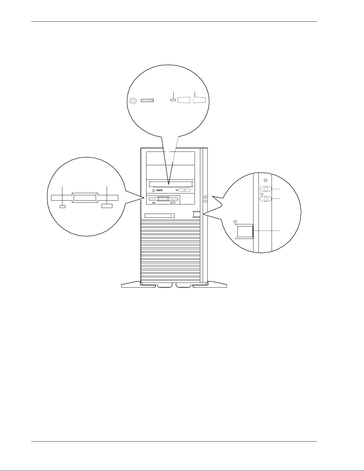
Front View
This figure shows the location of the front system controls and
indicators.
CD
B
A
POWER
DISK
E
F
POWER
G
Load/eject b utton, CD-ROM reader Press to load CD and eject CD.
A.
Activity light, CD-ROM reader When lit, CD-ROM reader is in use.
B.
Activity light, 3 ½-inch dis kette drive When lit, diskette is in use.
C.
Eject button, 3 ½-inch di skette drive Press to eject diskett e.
D.
Power-on light When lit, DC power is p resent.
E.
Drive a c tivity light When lit, hard disk d rives ar e in use.
F.
DC power switch Press to turn system DC power on or off.
G.
2-4 Setting Up the System
Front Features and Controls
Page 31

Rear View
This figure shows the location of the following rear system controls and
indicators.
A
B
C
E
G
I
K
L
D
F
H
J
M
N
O
115V
AC input power connector Supplies AC power to the power s upply.
A.
Line voltage select or swi tch Selects AC input power of 115 VAC or 230 V AC.
B.
Keyboard PS/2-compatible 6-pin mi ni-DIN connector.
C.
Mouse PS/2-compat ib le 6-pin mini-DIN c onnector.
D.
COM1 COM1 serial port 9-pin connector.
E.
Printer 25-pin pa r a llel port con ne ctor.
F.
COM2 COM2 serial port 9-pin connector.
G.
Green L AN st atus lig h t When lit, LAN is linked to network (see follow ing table).
H.
LAN connector RJ-45 Connector
I.
Orange LAN status light When lit, 100 Mbps LAN connect io n (see f ollowing table).
J.
USB connectors Two USB Connectors.
K.
VGA VGA monitor 15-p in connector.
L.
PCI slots Three PCI add-in board slot locations.
M.
Comb o P C I/ISA slot One PCI or ISA slot locati on.
N.
ISA slot One ISA add -in boar d s lot location.
O.
Rear Features and C ontrols
Setting Up the System 2-5
Page 32

LAN Status Lights
Color Meaning When On Meaning When Blinking Meaning When Off
Orange 100 Mbps network
connection
Green Linked t o network , no
network traffic
Making C onn ections
If your system normally operates without a video display or keyboard
(for example, as a network server), you must install a video display and
keyboard to configure the system. You may remove them after running
the System Setup Utility (SSU). For information on running the SSU,
refer to Appendix B of this User’s Guide.
Refer the following figure and connect your keyboard, monitor, and
mouse. Connect any external peripheral devices such as a printer or
modem by following the instructions included with these devices.
!
Damage to the system may r esul t if the keyboard/ m ouse
cable is inserted or r em oved when power is appli ed to the
system.
None 10 Mbps network
connectio n
Linked to network,
sending or receiving data
Not linked to network
CAUTION
Inserting a te lephone line connector into a LAN boa r d R J -45
port may result in personal injury and equipment damage.
2-6 Setting Up the System
Page 33

BA
115V
C
D
E
F
G
H
I
J
Keyboard
A.
Mouse
B.
Serial Port 1 (COMM1)
C.
Printer
D.
Serial Port 2 (COMM2)
E.
LAN
F.
Video Display (VGA)
G
PCI slots
H.
Combo PCI/ISA slot
I.
ISA slot
J.
Making Connections
Setting Up the System 2-7
Page 34

Setting the Line Voltage
The system contains a 260 watt power supply that is switch-selectable
for 115 or 230 VAC at an operating frequency of 50/60Hz. The power
supply voltage selection switch is factory set to 115Vac for systems
used in the United States; it is set to 230Vac for systems used in
Europe. Line source voltages between 200 and 230 VAC are acceptable
when the power supply input voltage is set to 230 VAC.
!
CAUTION
Before you plug the system power cord i nto an AC outlet,
ensure the input l ine voltage settin g f or the power supply is
correct.
To use the system wi th l in e so ur ce voltages betwee n 200 a nd
230 VAC, the line voltag e selector switch on the po wer supply
must be set to 230. If you set the sw itc h to t he 115 VAC
position, the power supply w ill be dam a ged w he n y ou plug in
your system.
If you need to change the line voltage setting, perform the following
steps.
If you are setting up your system for the fir st time, the
Note:
power cord will not be connect ed to the rear panel of your system.
1.
Unplug the AC power cord from the back of the chassis.
2.
Insert the tip of a small screwdriver or ball-point pen into the
depression on the line voltage selector.
3.
Slide the selector switch to the left for 115 VAC or to the right for
230 VAC.
2-8 Setting Up the System
Page 35

115V
115V
115V
A
or
B
230V
A.
B.
Voltage selector switch set to 115 VAC
Voltage selector switch set to 230 VAC
Setting the Line Voltage
Setting Up the System 2-9
Page 36

Connecting the Powe r Cord
Plug the female end of the AC power cord into the input receptacle on
the rear of the power supply cage. Plug the male end of the power cord
into NEMA 5-15R outlet for 100-120 VAC or NEMA 6-15R outlet for
200-240 VAC.
If the power cord supplied with the system is not compatible with the
AC wall outlet in your region, obtain a suitable power cord that meets
the following criteria.
The power cord must be rated for the available AC voltage and have a
current rating that is at least 125% of the current rating of the
system.
The power cord connector that plugs into the wall outlet must be
terminated in a grounding-type male plug designed for use in your
region. It must have certification marks showing certification by an
agency acceptable in your region.
The power cord connector that plugs into the system must be an
IEC- type CEE-22 female connector.
The power cord must be less than 1.8 meters (6.0 feet) long.
!
WARNING
Your system shipped with a power cor d. Do not attempt to
modify or use the supplied AC power cord if it is not the e xact
type required.
2-10 Setti ng Up the System
Page 37

Powerin g On Your System
Power on your system as follows.
1. Make sure all external devices, such as a video display, keyboard,
and mouse (optional) have been connected, and the power cords are
connected.
2. Power on the video display and any other external devices.
3. Press the push-button power on/off switch on the front panel. Verify
that the power-on LED is lit. If it is not lit, ensure the ac power cords
are connected to a functional ac power source.
After a few seconds your system begins the internal Power-On Self Tests
(POST). POST automatically checks the system board, CPU module,
memory, keyboard, and most installed peripheral devices.
!
CAUTION
Always allow POST to complete before powering down your
system.
!
CAUTION
The server m a na gement logic on y our system board m on itors
and logs syst em voltage changes. When power ing down your
system you m a y experience a
1–5 second delay f rom the time you press t he push-button
power on/off swit ch on the front panel and yo ur system
powering down. This is normal syst em operation and i s
required by the server management logic.
If you have problems powering on your system, refer to Problem Solving
in Chapter 5 of this User’s Guide.
After you have successfully powered on your system, insert the
XPRESSBUILDER
E
and follow the screen prompts to run E
CD-ROM into the CD-ROM device, reboot the system
XPRESSBUILDER
.
Setting Up the System 2-11
Page 38

2-12 Setti ng Up the System
Page 39

Configuring Your System
!
Configuring Your System
!
BIOS Setup Utility
!
Symbios Configuration Utility
!
Optional RAID Controller
!
Configuring System Board Jumpers
3
Page 40

Configuring Your System
This Configuration and setup utilities are used to change your system
configuration. You can configure your system, as well as option boards
you may add to your system, using the BIOS Setup Utility. Several
unique system parameters are configured using the BIOS Setup, which
is stored in the system FLASH memory.
You can also configure your system, including reserving resources
required by option boards, using the System Setup Utility (SSU). Also,
the SSU is used to read stored system event information. Information
on the SSU may be found in Appendix B of this User’s Guide.
The Symbios Configuration Utility detects the SCSI host adapters on
the system board. Use this utility if you need to configure the SCSI
controller in your system or to perform a SCSI disk format or verify disk
operation on the SCSI disk drives. The Symbios Configuration Utility is
also used to configure any SCSI removable media devices installed in
your system.
If your system has been factory configured, the SSU, BIOS Setup, or
Symbios Configuration Utility do not need to be run unless you want to
change the password or security features, add certain types of option
boards or devices, or upgrade your system board.
This chapter also provides information on several system configuration
parameters that are set by jumpers on the system board. However,
these parameters do not usually require change.
Use the EXPRESSBUILDER CD-ROM to create the device driver and
SSU diskettes.
3-2 Configuring Your System
Page 41

BIOS Setup Utility
The BIOS Setup Utility is used to change system configuration
parameters. This utility has some unique parameters and many
parameters that are also configurable with the SSU. The utility is
resident in the system FLASH memory and does not require a diskette
or an operating system present to run. However, parameters set with
the BIOS Setup Utility that can also be set with the SSU, will be
overwritten by the SSU the next time the SSU is run.
Using the BIOS Setup Utility
You access the BIOS Setup utility when you turn on or reboot your
system. To run the BIOS Setup Utility, perform the following procedure:
Power-on or reboot the system. “Press <F2> to enter SETUP”
1.
displays.
2. Press F2. The BIOS Setup Utility starts and the Main Menu is displayed. The menu
bar at the top of the Main Menu lists the following selections:
Menu Use
Menu Bar Selections
Main Use this menu for basic system configuration.
Advanced Use this menu for setting the Advanced Features available on
your system.
Security Use this menu to set User and Supervisor Passwords and the
Backup and Virus-Check reminders.
Server Use this menu for configuring Server Management features.
Boot Use this menu to configure Boot Device priority.
Exit Exits the current menu.
Use the arrow keys to select a menu or an item on a displayed
menu. Press the value keys (listed in the table below) to cycle
through the allowable values for the selected field. Use the Exit
menu’s “Save Values” selection to save the current values on all the
menus.
To display a submenu, position the cursor on a selection that has a
submenu and press
ENTER
. Selections with submenus are preceded
by an arrow.
Refer to the following table for information on the keys you use with
BIOS Setup. These keys are also listed at the bottom of the Setup
menu.
Configuring Your System 3-3
Page 42

Key Function in Setup Menu
F1 or Alt-H Get Help about an item.
ESC Exit the current menu and return to the previous
menu.
Left or right arrow
keys
Up or down arrow
keys
HOME or END Move cursor to top or bottom of window.
PAGE UP or PAGE
DOWN
F5 or - Select the previous value for the field.
F6 or + or SPACE Select the next value for the field.
F9 Load default configuration values for this menu.
F10 Save configuration values and exit.
ENTER
Move between menus.
Move cursor up and down. The cursor moves only
to the settings that you can change.
Move cursor to next or previous page.
Execute command or Select submenu.
BIOS Setup Configuration Settings
The BIOS Setup Configurations tables show the default settings for the
BIOS Setup Utility and provides a place for you to record any changes
you make to these settings. Recommended values are bold in the
following tables.
3-4 Configuring Your System
Page 43

Main Menu
Feature Choices Description Your Setting
System Time HH:MM:SS Sets the system time.
System Date MM/DD/YYYY Sets the system date.
Legacy Diskette A: Disabled
360KB
1.2 MB
720KB
1.44/1.25 MB
2.88 MB
Legacy Diskette B:
Primary IDE Master
Primary IDE Slave
Secondary IDE Master
Secondary IDE Slave
Keyboard Features
Processor Settings
Disabled
360KB
1.2 MB
720KB
1.44/1.25 MB
2.88 MB
ENTER
Press
ENTER
Press
ENTER
Press
ENTER
Press
ENTER
Press
Press ENTER
Selects the diskette type. The1.25 MB
diskette requires a 3-mode diskette drive.
Selects the diskette type.
Refer to “Primary IDE Master and Slave
Submenu.”
Refer to “Primary IDE Master and Slave
Submenu.”
Refer to “Secondary IDE Master and
Slave Submenu.”
Refer to “Secondary IDE Master and
Slave Submenu.”
Refer to “Keyboard Submenu.”
Refer to “Processor Settings Submenu.”
Language
English (US)
French, Spanish,
German, Italian
Selects which language BIOS displays.
Configuring Your System 3-5
Page 44

Primary/Secondary IDE Master and Slave Submenu
Feature Choices Description Your Setting
Type
Cylinders 0 to 65535 Number of cylinders on drive. This field is
Heads 1 to 16 Number of read/write heads on drive. This
Sectors 0 to 63 Number of sectors per track. This field is
Auto
None
CD-ROM
IDE Removable
ATAPI
User
Auto allows the system to attempt autodetection of the drive type.
None informs the system to ignore this
drive.
CD ROM allows the manual entry of some
fields described below.
Determines that a removable IDE drive is
installed. IDE allows the manual entry of
fields described below.
Determines that a removable ATAPI drive
is installed. ATAPI allows the manual
entry of fields described below.
User allows the manual entry of all fields
described below.
changeable only for Type User.
field is changeable only for Type User.
changeable only for Type User.
Maximum
Capacity
Multi-Sector
Transfer
LBA Mode
Control
32 Bit I/O Disabled
Transfer Mode
Ultra DMA
Mode
N/A Computed drive size. This field is
Disabled
2, 4, 8, or 16
sectors
Disabled
Enabled
Enabled
Standard
Fast PIO 1
Fast PIO 2
Fast PIO 3
Fast PIO 4
FPIO 3/DMA 1
FPIO 4/DMA 2
Disabled
Mode 0
Mode 1
Mode 2
informational only for Type User.
Determines the number of sectors per
block for multi-sector transfers. This field
is informational only for Type Auto.
Enabling LBA causes logical block
addressing to be used in place of
cylinders, heads, and sectors. This field is
informational only for Type Auto.
Enabling allows 32 bit IDE data transfers.
Selects the method for moving data to and
from the drive. This field is informational
only for Type Auto.
Selects the Ultra DMA Mode for moving
data to and from the drive.
3-6 Configuring Your System
Page 45

Keyboard Submenu
Feature Choices Description Your Setting
NumLock On
Off
Key Click
Keyboard
auto-repeat
rate
Keyboard
auto-repeat
delay
Disabled
Enabled
30/sec
26.7/sec
21.8/sec
18.5/sec
13.3/sec
10/sec
6/sec
2/sec
1/4 sec
1/2 sec
3/4 sec
1 sec
Selects power-on state for Num Lock.
Enables or disables key click.
Selects the number of times per second a
key will repeat while it is held down.
Selects delay before key repeat.
Processor Settings Submenu
Feature Choices Description Your Settings
CPU Speed
Settings
Processor Speed
List
Processor speed list is determined by the
speed of the processor(s) installed. Select
speed to match speed of installed
processor(s).
speed above the speed of the installed
processor(s).
Caution:
DO NOT select a
Processor
Retest
Processor
Serial Number
Memory Cache
No
Yes
Disabled
Enabled
Enabled
Disabled
Select Yes if you want the BIOS to clear
old processor status and retest all
processors on next boot.
Controls detection of processor serial
number.
Pentium III is installed.
Enables processor cache.
Note:
displays only when
Configuring Your System 3-7
Page 46

Advanced Menu
Feature Choices Description Your Setting
Install OS
Other
Win95
WinNT 5.0
Select the operating system installed in
your system.
Reset
Configuration
Data
PCI
Configuration
Integrated
Peripherals
Configuration
Advanced
Chipset Control
Large Disk
Access Mode
Delay on Option
ROMs
No
Yes
ENTER
Press
ENTER
Press
ENTER
Press
LBA
CHS
Disabled
Enabled
PCI Configuration Submenus
This submenu should only be changed by qualified technical personnel.
Select Yes if you want to clear the system
configuration data during next boot.
System automatically resets to No in next
boot.
Refer to “PCI Configuration Submenu.”
Refer to “Intergrated Peripherals
Configuration Submenu.”
Refer to “Advanced Chipset Control
Submenu.”
Select LBA for IDE drives. This only
affects IDE drives with partitions greater
than 512 Mbytes.
Forces a short delay at the end of each
Option ROM scan.
!
CAUTION
Leave PCI Configuration Submenu at factory-default settings.
This submenu should only be changed by a technically qualified
person.
PCI Configuration Submenu
Feature Choices Description Your Setting
ENTER.
PCI Device, Embedded
SCSI Devices
Option ROM Scan
Enable Master
Latency Timer Default
Press
Enabled
Disabled
Enabled
Disabled
0020h
0040h
0060h
0080h
00A0h
00C0h
00E0h
N/A
Enables option ROM scan of the selected
device. Used to enable embedded
Symbios SCSI controller
Enabled selects the device as a PCI bus
master.
Minimum guaranteed time, in units of PCI
bus clocks, that a device may be master
on a PCI bus. Caution: Do not change this
setting unless you fully understand the
priority of this device on the PCI bus.
3-8 Configuring Your System
Page 47

PCI Device, Slot 1 - Slot 4 Submenus
This submenu should only be changed by qualified technical personnel.
!
CAUTION
Leave PCI Device Submenu at factory-default settings.
submenu should only be changed by a technically qualified person.
PCI Device, Slot 1 - Slot 4 Submenu
Feature Choices Description Your Setting
Enable Master
Latency Timer Default
Enabled
Disabled
020h
040h
060h
080h
0A0h
0C0h
0E0h
Enables selected device as a PCI bus
master.
Minimum guaranteed time, in units of PCI
bus clocks, that a device may be master
on a PCI bus. Caution: Do not change this
setting unless you fully understand the
priority of this device on the PCI bus.
This
Configuring Your System 3-9
Page 48

Integrated Peripheral Configuration Submenu
Feature Choices Description Your Setting
COM 1:
(Serial Port A)
Disabled
Enabled
Auto
OS Controlled
Auto forces BIOS to configure the port.
OS Controlled forces OS to configure the
port. If this COM port is used for Console
Redirection make sure I/O and IRQ are
identical to the values in the server Setup
Menu.
Base I/O Address
Interrupt IRQ 3
COM 2:
(Serial Port B)
Base I/O Address 3F8
Interrupt
Parallel Port Disabled
Mode Output only
3F8
2F8
3E8
2E8
IRQ 4
Disabled
Enabled
Auto
OS Controlled
2F8
3E8
2E8
IRQ 3
IRQ 4
Enabled
Auto
OS Controlled
Bi-directional
EPP
ECP
Selects the base I/O address for COM
port 1.
Selects the IRQ for COM port 1.
Auto forces BIOS to configure the port.
OS Controlled forces OS to configure the
port. If this COM port is used for Console
Redirection make sure I/O and IRQ are
identical to the values in the server Setup
Menu.
Selects the base I/O address for COM
port 2.
Selects the IRQ for COM port 2
Auto forces BIOS to configure the port.
OS Controlled forces OS to configure the
port.
Selects parallel port mode.
Base I/O Address
Interrupt IRQ 5
DMA channel DMA 1
Floppy disk controller Disabled
378
278
IRQ 7
DMA 3
Enabled
3-10 Configuring Your System
Selects the base I/O address for LPT port.
Not available in ECP or EPP modes.
Selects the IRQ for LPT port.
Selects the DMA for LPT port.
Enables onboard diskette controller.
Page 49

Advanced Chipset Control
Feature Choices Description Your Setting
640 – 768K Memory
Region
Enabled
Disabled
Enabled forwards ISA Master and DMA
cycles to the PCI bus. Disabled forwards
these cycles to memory.
Delayed Transaction Disabled
Enabled
Passive Release Disabled
Enabled
Enable the delayed transaction
mechanism when PIIX4 is target of a PCI
transaction.
Enable the Passive Release mechanism
on PHOLD# signal when PIIX4 is a PCI
MASTER.
Security Menu
Note:
password for entering Setup. The passwords are not case sensitive.
Feature Choices Description Your Setting
User Password is
Administrator Password
is
Enabling the Administrtor Password field requires a
Security Menu
Clear
Set
Clear
Set
Status only; user cannot modify. Once set,
this can be disabled by setting it to a null
string, or by clearing password jumper on
system board (see
Board Jumpers
Status only; user cannot modify.
Configuring System
).
Set User Password
Press
ENTER
When the <Enter> key is pressed, the
user is prompted for a password; press
ESC key to abort. Once set, this can be
disabled by setting it to a null string, or by
clearing password jumper on system
board (see
Jumpers
Configuring System Board
).
Configuring Your System 3-11
Page 50

Security menu (Continued)
Feature Choices Description Your Setting
ENTER
Set Administrator
Password
Press
When the <Enter> key is pressed, the
user is prompted for a password; press
ESC key to abort. Once set, this can be
disabled by setting it to a null string, or by
clearing password jumper on system
board (see
Jumpers
Configuring System Board
).
Password on Boot
Diskette Access Administrator
Fixed Disk Boot Sector
Secure Mode Timer
Secure Mode Hot Key
(Ctrl-Alt- )
Secure Mode Boot
Disabled
Enabled
User
Normal
Write Protect
Disabled
1 min
2 min
5 min
10 min
20 min
1 hr
2 hr
[ ]
[A, B, ..., Z]
Disabled
Enabled
Requires password entry before boot.
System will remain in secure mode until
password is entered. Password on Boot
takes precedence over Secure Mode
Boot.
Controls access to diskette drives.
Write-protects boot sector on hard disk to
protect against viruses.
Period of key/PS/2 mouse inactivity
specified for secure mode to activate. A
password is required for secure mode to
function. Cannot be enabled unless at
least one password is enabled.
Key assigned to invoke the Quicklock
feature. Cannot be enabled unless at least
one password is enabled.
System will boot in secure mode. The
user must enter a password to unlock the
system. Cannot be enabled unless at
least one password is enabled.
Video Blanking
Floppy Write Protect
Disabled
Enabled
Disabled
Enabled
3-12 Configuring Your System
Blank video when secure mode is
activated. The user must enter a
password to unlock the system. Cannot
be enabled unless at least one password
is enabled.
When secure mode is activated, the
diskette drive is write protected. The user
must enter a password to disable. Cannot
be enabled unless at least one password
is enabled.
Page 51

Server Menu
Feature Choices Description Your Setting
ENTER
System Management
Console Redirection
Press
Press
ENTER
Refer to “System Management Submenu.”
Refer to “Console Redirection Submenu.”
Processor Retest Yes
No
PERR# Reporting
SERR# Reporting
Disabled
SMI Only
SMI & NMI
Disabled
Enabled
Select Yes to have BIOS clear all
processor status and retest the
processor(s) on bootup.
If selected, system will detect and report
PERR on PCI buses.
If enabled, system will detect and report
SERR on PCI buses.
Configuring Your System 3-13
Page 52

System Management Submenu
Feature Choices Description Your Setting
ENTER
Sever Management Info
Press
Refer to “System Management Info
Submenu.”
System Event Logging Disabled
Enabled
Clear Event Log
Front Panel Clear
CMOS
EMP Password switch
EMP Password
EMP ESC Sequence +++
EMP Hangup Line
String
Modem Init String Refer to your
High Modem Init String Refer to your
No
Yes
Disabled
Enabled
Disabled
Enabled
[A…Z, 0 9]
Refer to your
modem
documentation.
modem
documentation.
modem
documentation.
When enabled, system events will be
logged by BIOS and BMC.
Yes clears the system event log (SEL) in
BMC.
Clear CMOS command: Press the Reset
button for 4 seconds and press Power
button for 1 second. Release the buttons
simultaneously.
Enables EMP password.
This field only shows up when EMP
password is enabled.
EMP Access Mode Pre-boot Only
Always Active
Disabled
EMP Restricted Mode
Access
EMP Direct
Connect/Modem Mode
Disabled
Enabled
Direct Connect
Modem Mode
Pre-boot Only - EMP is only enabled
during power down through power up to
the end of POST. Com 2 is returned to
system use at the end of Post when
operating system boots.
Always Active - EMP is always enabled.
Com 2 cannot be used by operating
system. It is now dedicated for EMP use.
Disabled - EMP is disabled. Com 2 is
always available for system use by
console redirection or operating system
If set to Enabled, Power on/off and Reset
server controls via EMP are no longer
available.
Sets how EMP connects to the server.
Direct Connect means a null modem
serial cable directly connects COM 2
connector port to the EMP console
machine.
Modem mode indicates that a modem is
connected on COM 2 for EMP use.
3-14 Configuring Your System
Page 53

Server Management Information Submenu
Items on this menu can not be modified by the user. If items require changes, consult
your system administrator.
Server Management Information Submenu
Feature Choices Description Your Setting
Board Part Number N/A Information field only
Board Serial Number N/A Information field only
System Part Number N/A Information field only
System Serial Number N/A Information field only
Chassis Part Number N/A Information field only
Chassis Serial Number N/A Information field only
BMC Revision N/A Information field only
Console Redirection Submenu
Feature Choices Description Your Setting
COM Port Address
IRQ # 3 or 4
Baud Rate 9600
Flow Control
Disabled
3F8
2F8
3E8
None
19.2k
38.4k
115.2k
No Flow Control
CTS/RTS
XON/XOFF
CTS/RTS + CD
When enabled, console redirection uses
the I/O port specified. 3F8 is typically
COM 1 and 2F8 is typically COM2. Make
sure these values are identical to those of
serial port A and B in the Peripheral
Configuration Setup Menu.
When console redirection is enabled, this
displays the IRQ assigned per the
address chosen in the COM Port Address
field.
Communications line dependent.
Communications line dependent.
Configuring Your System 3-15
Page 54

Boot Menu
Feature Choices Description Your Setting
ENTER
Boot Device Priority
Hard Drive
Removable Devices
Press
Press
Press
ENTER
ENTER
Boot Device Priority Submenu
Use the up or down arrow keys to select a device, then press the <+> or <-> keys to
move the device higher or lower in the boot priority list.
Boot Priority Device Description Your Setting
1.
Removable
Devices
.
.
.
Refer to “Boot Device Priority Submenu.”
Refer to “Hard Drive Submenu.”
Refer to “Removeable Devices Submenu.”
Boot Device Priority Submenu
Attempts to boot from a removable media
device.
2. ATAPI CD-ROM
Drive
3. Hard Drive Attempts to boot from a hard drive device.
4.
LANDesk® Service
Agent II
Attempts to boot from an ATAPI CD-ROM
drive.
Attempts to boot from diagnostic boot
partition of the flash memory.
3-16 Configuring Your System
Page 55

Hard Drive Submenu
For options on this menu, use the up or down arrow keys to select a device, then press
the <+> or <-> keys to move the device higher or lower in the boot priority list.
Option Description
1. Hard Drive #1 (or
actual drive string)
IDE drives will have a suffix attached to the drive ID string:
PM - hard drive on Primary Master Channel
PS - hard drive on Primary Slave Channel
SM - hard drive on Secondary Master Channel
SS - hard drive on Secondary Slave Channel
SCSI CD-ROMs will be displayed here because the onboard Symbios SCSI bios treats
CD-ROMs as hard drives.
SCSI removable drives will also appear here.
Hard Drive Submenu
2. Other Bootable
Device
Covers all the boot devices that are not reported to the system BIOS through the BIOS
boot specification mechanism. This includes all PCI cards that are not bios boot compliant
(legacy) as well as ISA cards that are not PnP compliant.. ISA legacy cards will boot first
before non bios boot compliant PCI cards (in scan order from lowest slot to highest).
Removable Devices
For options on this menu, use the up or down arrow keys to select a device, then press
the <+> or <-> keys to move the device higher or lower in the boot priority list.
Removable Devices Submenu
Option Description
1. Legacy Floppy Drive Refers to the onboard 3.5” floppy drive.
Configuring Your System 3-17
Page 56

Exit Menu
You can make the following selections on the Exit Menu. Select an option using the up
or down arrow keys, then press <Enter> to execute the option. Pressing <Esc> does not
exit this menu. You must select one of the items from the menu or menu bar to exit.
Exit Menu
Choices Description
Exit Saving Changes Exits after writing all modified Setup item values to CMOS.
Exit Discarding Changes Exits leaving CMOS unmodified.
Load Setup Defaults Loads default values for all Setup items.
Load Custom Defaults
[ENTER]
Save Custom Defaults
[ENTER]
Discard Changes Reads the previous value of all Setup items from CMOS.
Save Changes Writes all Setup item values to CMOS.
Loads settings from custom defaults.
Saves present Setup values to custom defaults.
3-18 Configuring Your System
Page 57

Symbios Configuration Utility
The Symbios Configuration Utility detects the SCSI host adapter located
on the system board. Use the utility to:
Change adapter and SCSI device default values
!
Check and/or change SCSI device settings that may conflict with
!
those of other devices in the server.
Perform low-level formatting or verify operations on SCSI disk drives.
!
Running the Symbios Configuration Utility
Power-on the system. The system boots up.
1.
When this message appears on the video monitor:
2.
Press Ctrl-C to start the Symbios Configuration Utility
Press
The utility starts and the Main Menu displays.
3.
Ctrl+C
to run this utility.
Symbios Configuration Utility Main Menu
IRQ Level
Number
SYM53C875 F800 11 On On* Yes
Change Adapter Status – Press ENTER twice to change adapter Next Boot Status.
Adapter Boot Order – Press ENTER to select and change boot order of each SCSI adapter.
Additional Adapter Configuration – Not used.
Display Mode-Verbose – Press ENTER to change display mode.
Mono/Color – Press ENTER to change display from black/white to color.
Language
Help
Quit
Current Next Boot
*Next Boot Status for this controller must be turned
StatusAdapter Port
OFF
if you install the optional
NVRAM
Found
Mylex AcceleRAID 250 Controller board in your system. Refer to “Change Adapter
Status” above.
The following keys are active for all SCSI Configuration screens:
Key Action
Arrows Up and down arrows move from one parameter to
another within a screen.
ENTER Displays options for a configurable parameter. Selects
an option.
ESC
Moves back to previous screen or parameter or EXIT if
at the Main menu.
Configuring Your System 3-19
Page 58

Changing the Adapter and Device Configurations
The SCSI Configuration Utility Main Menu lists the onboard SCSI
adapter and shows its current settings. The adapter controls the
operation of the SCSI devices in your system (hard disk drives or
removable media devices).
Select “Adapter Setup” and press
1.
ENTER
displays.
Adapter Setup Screen
Description Recommended Setting or
Display Only
SCAM Support On
Parity On
Host SCSI ID 7
Scan Order Low to High
Removable media support None
CHS Mapping SCSI Plug and Play Mapping
Highlight the function you want to change and press
2.
will be prompted to save changes when you exit the configuration
utility.
To change device configuration parameters, perform the following steps:
. The Adapter Setup screen
Your Configuration
ENTER
. You
At the SCSI Configuration Utility Main Menu, select “Device
1.
Selections” and press
Select the SCSI device you are reconfiguring and press
2.
ENTER
. The Devices 0 to 7 screen displays.
ENTER
you are configuring SCSI Hard Disk Drives, refer to the "SCSI Hard
Disk Drives" Table below; if you are configuring SCSI Removable
Media Devices, refer to the "SCSI Removable Media Devices" Table
below for recommended settings.
. If
3-20 Configuring Your System
Page 59

SCSI Hard Disk Drives
Description Recommended Setting or
Display Only
Your Configuration
Dev0Dev1Dev2Dev
3
Device Selections Press
device and press
Sync Rate 40
Width (bits) 16
Disconnect On
Read/Write I/O timeout (secs) 10
Scan for device at boot time Yes
Scan for SCSI LUNS No
Queue Tags On
SCSI Removable Media Devices
Display Only
Device Selections Press
device and press
ENTER
ENTER
for menu. Select
ENTER
for menu. Select
ENTER
.
.
Your ConfigurationDescription Recommended Setting or
Dev0Dev1Dev2Dev
3
Sync Rate 10
Width (bits) 8
Disconnect On
Read/Write I/O timeout (secs) 10
Scan for device at boot time Yes
Scan for SCSI LUNS No
Queue Tags On
Highlight the function you want to change and press
3.
will be prompted to save changes when you exit the configuration
utility.
Note:
select “Format” or “Verify” from the Device Setup menu.
If you wish to format a disk or verify disk media,
ENTER
. You
Configuring Your System 3-21
Page 60

Optional RAID Controller
Factory Installed Controller
One of the options available for your system is the dual channel Mylex
AcceleRAID 250 (
system the added security of fault tolerance.
If you order a system with the RAID controller, the system is preconfigured at the factory. Refer to the “RAID Configurations” table to
determine how the RAID controller was configured at the factory. If you
want to reconfigure disk arrays and logical drives, you must run the
AcceleRAID 250 BIOS Configuration Utility; if you want to change the
RAID level, you must run the Mylex Disk Array Controller Utilities
(DACCF) software. Refer to the AcceleRAID 250 documentation included
with your system for information on running the AcceleRAID250 BIOS
Configuration Utility and the DACCF Utility.
NEC SecuRAID 210)
RAID Configurations
Controller board, which gives your
er of Hard Drives RAID Level
Configured
JBOD 1 JBOD (RAID 0) JBOD is an acronym for Just
1 2 Mirroring (RAID 1) Drives are paired and
5 3 Striping with Parity (RAID 5) Data is striped
5 3 plus 1 hot
ore _ _ The first four disks are as stated above; the
Hard Drives in
Array
spare drive
Description
a Bunch Of Disks. Each drive can operate
independently as with a common host bus
adapter; or multiple drives may be spanned
and seen as a single very large drive. No
redundancy is provided.
mirrored. All data is 100% duplicated on an
equivalent drive (fully redundant).
across several physical drives. Parity
protection is used for data redundancy.
Striping with Parity (RAID 5) Data is striped
across three physical drives. Parity protection
is used for data redundancy. This drive is used
as the “Hot Spare.”
remaining disks are not part of the array, but
are ready to be configured.
3-22 Configuring Your System
Page 61

Add-on Controller
If you are adding the RAID controller to an existing system, the
AcceleRAID™ 250 BIOS Configuration Utility allows you to configure
disk arrays and logical drives in your system. Since the utility resides in
the AcceleRAID™ 250 BIOS on the RAID controller, its operation is
independent of the operating system in your server. Refer to Chapter 4
in this User’s Guide for information on installing an add-in option
board. Refer to Chapter 4 of the AcceleRAID™ 250
information on running the AcceleRAID™ 250 BIOS Configuration
Utility.
Installation Guide for
Note:
controller must be turned
Mylex AcceleRAID 250 Controller board in your system. Refer
to “Symbios Configuration Utility” found earlier in this
chapter.
Next Boot Status for the first Symbios SYM53C875
DACCF Configuration Utility
The DACCF utility is included with the RAID controller. The
AcceleRAID™ 250 supports various versions of RAID technology
(referred to as RAID levels). To use any RAID level, you must configure
the RAID controller using the DACCF Configuration Utility prior to
installing your Network Operating System. For an explanation of this
utility, refer to the
that was shipped with the controller. Chapter 2 (
covers array hardware preparation, configuration, and initialization.
After completing the steps in Chapter 2, you can install your Network
Operating System.
Disk Array Controller Configuration Utilities Manual
OFF
if you install the optional
Preparing the Array)
Configuring Your System 3-23
Page 62

Configuring System Board Jumpers
Before You Begin
Only a qualified technical person should perform the procedures in this
section.
!
CAUTION
Electrostatic discharge (ESD) can damage the
system board. Modify the system board only at an
ESD workstation. Otherwise, wear an antistatic
wrist strap attached to chassis ground.
The system board jumpers enable you to set specific operating
parameters for your system. A jumper is a small plastic-encased
conductor (shorting plug) that slips over two jumper pins.
The “System board Jumpers” illustration shows the location of the
system board jumpers. The “System Board Jumper Configurations”
table lists the system board jumpers and their factory default settings.
J7B1
G
J3J1
31
9
5
1
A
B
C
J2J1
9
5
1
System Board Jumpers
D
E
F
3-24 Configuring Your System
Page 63

System Board Jumper Summary
Jumper Block Pins (default in bold) What it does at system reset
A.
Block Write
Protect
B.
BMC Forced
Update Mode
C.
BIOS Boot
Block Write
Protect
D.
Recovery Boot
E. Password Clear
F. CMOS Clear
9-10, Protect
10-11, Erase BMC boot block is erasable and programmable.
5-6, Normal
6-7, Program System tries to update BMC firmware.
1-2, Protect
2-3 Erase BIOS boot block is erasable and programmable.
9-10, Normal
10-11, Recovery BIOS attempts a recovery boot, loading BIOS
5-6, Protect
6-7, Erase Clears the password.
1-2, Protect
2-3, Erase Replaces the contents of NVRAM with the
BMC boot block is write protected.BMC Boot
System boots normally.
BIOS boot block is write-protected.
System attempts to boot using the BIOS stored
in flash memory.
code from a floppy diskette into the flash
device. This is typically used when the BIOS
code has been corrupted.
Maintains the current system password.
Preserves the contents of NVRAM.
manufacturing default settings.
G. Reserved
1-2, Disabled
Required on factory default.
Configuring Your System 3-25
Page 64

Moving System Board Jumpers
!
CAUTION
Before doing the procedures in this section, make sure that
your system is powered off and unplug the AC power cord
from the back of the chassis. Failure to disconnect power
before moving the jumpers can result in personal injury and
equipment damage.
Observe static precautions. Use an antistatic wrist strap.
To configure the system board options:
Power off the system and remove the left panel as described in
1.
Chapter 4 of this guide.
Check to ensure the system power cord is removed from the back of
2.
the system.
Locate the position of the jumpers on the system board you are
3.
changing. To change a jumper setting, use a pair of needle-nose
pliers or your fingers to remove the jumper from its current location.
Position the jumper over the two pins for the desired setting and
press it onto the pins. Be careful not to bend the pins. Refer the
System Board Summary table for system board jumper settings.
Install the system cover and power up the system.
4.
3-26 Configuring Your System
Page 65

Resetting the CMOS NVRAM
To reset the CMOS NVRAM:
Power down the your system. Remove the left side panel as
1.
described in Chapter 4 of this User’s Guide.
Move the CMOS Clear jumper from pins 1-2 to pins 2-3. Refer to
2.
“Configuring System Board Jumpers” to see the location of this
jumper.
Power on the system. Wait for POST to complete and for the
3.
messages “Invalid NVRAM setting” and “Press F2 to enter Setup” to
appear. This automatically reprograms CMOS and RTC to their
default settings.
Power off the system.
4.
Move the CMOS Clear jumper back to pins 1-2.
5.
Replace the left side panel and power on the system.
6.
Run the BIOS Setup Utility to check the configuration of your
7.
system.
Clearing and Changing the Passwords
To clear and change the passwords:
Power down the your system. Remove the left side panel as
1.
described in Chapter 4 of this User’s Guide.
Move the Password Clear jumper from pins 5-6 to pins 6-7. Refer to
2.
“Configuring System Board Jumpers” to see the location of this
jumper.
Power on the system and wait for POST to complete. This
3.
automatically clears the old password.
Power off the system.
4.
Move the Password Clear jumper back to pins 5-6.
5.
Replace the panel and power on the system.
6.
To specify a new password run the BIOS Setup Utility as described
8.
earlier in this chapter.
Configuring Your System 3-27
Page 66

Recovering the BIOS
This procedure should only be performed by qualified technical
personnel.
Leave Recovery Boot jumper at factory-default setting.
This jumper should only be moved by a technically qualified
person.
Boot Block Write Protect
This procedure should only be performed by qualified technical
personnel.
Leave boot block jumper at factory-default setting:
Programming the boot block incorrectly will prevent the
system from booting. Programming
technically qualified person. The procedure requires a special
“Boot Block Update Utility.” Contact your dealer or sales
representative for more information.
!
CAUTION
!
CAUTION
should only be done
by a
BMC Forced Update Mode
This procedure should only be performed by qualified technical
personnel.
Leave BMC Forced Update Mode jumper at factory-default
setting:
booting. Programming
person. Contact your dealer or sales representative for more
information.
Setting this jumper incorrectly will prevent the system from
should only be done
!
CAUTION
by a technically qualified
3-28 Configuring Your System
Page 67

Upgrading Your System
!
Static Precautions
!
Preparing Your System for Upgrade
!
Equipment Log
!
Removing a Side Panel
!
Installing a Side Panel
!
Modifying the System Board
!
Option Boards
!
Hard Disk Drives
4
!
Front Panel
!
Removing EMI Shields and Filler Panels
!
Removable Media Devices
Page 68

!
WARNING
The DC push-button on/off switch on the front panel does not
turn off the system AC power. Also, +5vdc is present on the
system board whenever the AC power cord is connected
between the system and an AC outlet. Before doing the
procedures in this manual, make sure that your system is
powered off and unplug the AC power cord from the back of
the chassis. Failure to disconnect power before opening your
system can result in personal injury and equipment damage.
!
CAUTION
The server management logic on your system board monitors
and logs system voltage changes. When powering down your
system you may experience a
1–5 second delay from the time you press the push-button
power on/off switch on the front panel and your system
powering down. This is normal system operation and is
required by the server management logic.
Operating your system with the side panels removed can
damage your system components. For proper cooling and
airflow, always replace the side panels before powering on
your system.
Contact your sales representative or dealer for a list of approved
optional peripheral devices.
Static Precautions
An electrostatic discharge (ESD) can damage disk drives, option boards,
and other components. You can provide some ESD protection by
wearing an antistatic wrist strap attached to chassis ground when
handling system components.
Electronic devices can be easily damaged by static electricity. To
prevent damage, keep them in their protective packaging when they are
not installed in your system.
!
CAUTION
4-2 Upgrading Your System
Page 69

Preparing Your System for Upgrade
Depending on the upgrade, you will need one or more of the following
tools:
Phillips screwdriver (#1 bit and #2 bit)
!
Flat-head screwdriver
!
Small needle nose pliers
!
Pen or pencil
!
ESD workstation or antistatic wrist strap (recommended)
!
Equipment Log
Use the equipment log form located at the end of this manual to record
the model and serial number of your system, all installed options, and
any other pertinent information specific to your system. You will need
this information when configuring your system.
Upgrading Your System 4-3
Page 70

Removing a Side Panel
To install options in your system, you must remove the side panel on
the left side of the system (as viewed from the front). The side panel on
the right side of the system (as viewed from the front) only has to be
removed when adding removable media devices. The right side panel
removes in the same manner as the left side panel.
!
CAUTION
For proper cooling and airflow, do not operate the system with
the side panels removed. Always replace the panels before
powering on the system.
!
WARNING
If you are removing the side panel after the system is set up,
you must first power off the system and all external devices.
Unplug
the system power cord
To remove a side panel:
1.
Power off the system and ensure it is disconnected from the ac wall
outlet.
2.
The side panel is secured to the chassis with three screws. Remove
the screws securing the side panel. Save the screws for reattaching
the side panel.
3.
Slide the side panel toward the rear of the chassis. This unlocks the
locking fingers behind the side panel.
4.
Pull the side panel up and away from the chassis.
4-4 Upgrading Your System
Page 71

Removing a System Side Panel
Installing a Side Panel
1.
Before replacing the side panel, make sure no tools or loose parts
have been left inside the system chassis.
2.
Make sure all option boards are firmly seated in their respective slots
and that all interior cables are properly connected.
3.
Insert the metal tabs on the top and bottom of the side panel into
their slots on the chassis. Slide the side panel forward as far as it
will go.
4.
Replace the three side panel retaining screws.
If your system is already set up, plug the system back in,
Note:
reconnect the peripherals, and power on the peripherals and system.
Upgrading Your System 4-5
Page 72

Modifying the System Board
The following sections provide procedures for upgrading and
configuring the system board in your system. Topics covered include:
Replacing the real-time clock battery
!
Replacing the Pentium II processor
!
Installing or removing DIMMs.
!
!
CAUTION
Electrostatic discharge (ESD) can damage add-in boards and
other components; place them on an antistatic surface.
Modify the system board only at an ESD workstation.
Otherwise, wear an antistatic wrist strap attached to chassis
ground.
Replacing the Real-time Clock Battery
You may need to replace the real-time clock battery because of its life
span. The battery (Vendor Part #CR2032) is a commodity part available
through many vendors. Notice the plus (+) sign on the battery. This sign
will assist you in correctly positioning the battery on the system board.
!
CAUTION
Danger of explosion if battery is incorrectly replaced. Replace
only with same or equivalent type recommended by
manufacturer. Dispose of lithium batteries as required by
local ordinance or as normal waste if no local ordinance
exists. Do not expose the component to excessive heat or fire.
Keep all batteries away from children
!
CAUTION
Observe static precautions. Use an antistatic wrist strap.
4-6 Upgrading Your System
Page 73

B
A
C
Replacing the Real-Time Clock Battery
1.
Power off the system and remove the left side panel as described
earlier in this chapter.
2.
Insert the tip of a small flat-bladed screwdriver, or equivalent, under
the plastic tab on the San-in plastic retainer (A in figure).
3.
Gently push down on the screwdriver to lift the battery (B).
4.
Remove the battery from its socket (C).
5.
Dispose of the battery according to local ordinance.
6.
Remove the new lithium battery from its package, and, being careful
to observe the correct polarity, insert it in the battery socket.
7.
Reinstall the plastic retainer on the lithium battery socket.
8.
Replace the side panel and turn on the system.
9.
Run the BIOS Setup to restore the configuration settings to the realtime clock.
Upgrading Your System 4-7
Page 74

Replacing the Pentium II Processor
This subsection provides the procedure for upgrading the Pentium II Processor in your
system. The Pentium II processor is packaged as a Single Edge Connector Cartridge
(SECC), packaged as a Single Edge Processor Package (SEPP), or packaged as a Single
Edge Connector Cartridge Version 2 (SECC2).
The SECC packaged cartridge includes:
processor core with an integrated 16 KB primary (L1) cache
!
secondary (L2) cache
!
thermal plate
!
back cover.
!
The SEPP packaged board includes:
processor core with an integrated 16 KB primary (L1) cache
!
secondary (L2) cache.
!
The SECC2 packaged cartridge includes:
processor core with an integrated 16 KB primary (L1) cache
!
secondary (L2) cache.
!
back cover.
!
!
CAUTION
Electrostatic discharge (ESD) can damage components; place them
on an antistatic surface. Modify the system board using an antistatic
wrist strap attached to chassis ground.
!
WARNING
If the system has been running, any processor and heat sink already
installed on the board will be hot. To avoid the possibility of a burn,
let the components cool for 10 minutes before continuing with the
procedures described here
4-8 Upgrading Your System
Page 75

Replacing the SECC Version
1.
Power off the system and remove the left side panel as described earlier in this
chapter.
2.
Press the processor latches toward the center of the SEC cartridge to free them from
the retention module, Item A in Figure "Removing a Processor" below.
3.
Lift the SEC cartridge upward, out of the retention module and place it on a
grounded, static-free surface or conductive foam pad.
A
Removing a Processor
A
4.
Remove the two clips that secure the heat sink to the old processor, see Figure
"Processor heat Sink Assembly" below.
5.
Remove the heat sink and thermal pad from the top of the old processor, see Figure
"Processor heat Sink Assembly" below.
6.
Put the old processor in a piece of conductive foam and store in an antistatic
package.
Processor Heat Sink Assembly
Upgrading Your System 4-9
Page 76

7.
Remove the new processor from its antistatic package and place it on a grounded,
static-free surface or conductive foam pad.
8.
Position the thermal pad on top of the new processor so that the holes in the thermal
pad line up with the holes in the processor.
9.
Position the heat sink on top of the new processor.
10.
Install the two clips that secure the heat sink to the processor.
11.
Position the processor back into the retention module. Ensure that the alignment
notch in the SEC cartridge fits over the plug in Slot 1. Push down firmly, with even
pressure on both sides of the top, until the SEC cartridge is seated.
12.
To lock in the processor, push the latches outward until they click into place in the
retention module, Item A in Figure "Removing a Processor" above. The latches
must be secured for proper electrical connection of the processor.
13.
After you have installed a new processor, you must run the BIOS Setup Utility (F2)
to configure its speed. Refer to Chapter 3, “Configuring Your System.”
14.
Replace the left side panel and power up the system.
4-10 Upgrading Your System
Page 77

Replacing the SEPP Version
1.
Power off the system and remove the left side panel as described earlier in this
chapter.
2.
Pull the processor latches, Item A in Figure "Removing a Processor" below, out
away from the edges of the SEPP to free them from the Universal Retention Module
(URM).
3.
Lift the SEP processor upward, out of the URM and place it on a grounded, staticfree surface or conductive foam pad.
Removing a Processor
4.
Remove the attachment clip, Item A in Figure "Processor Heat Sink Assembly"
below, that secures the heat sink to the old processor.
5.
Remove the heat sink, Item C in Figure "Processor Heat Sink Assembly" from the
front of the old processor, Item B in Figure "Processor Heat Sink Assembly" below.
6.
Put the old processor in a piece of conductive foam and store in an antistatic
package.
Processor Heat Sink Assembly
Upgrading Your System 4-11
Page 78

7.
Remove the new processor from its antistatic package and place it on a grounded,
static-free surface or conductive foam pad.
8.
Position the heat sink, Item C in Figure "Processor Heat Sink Assembly" above, on
the front of the new processor so that the holes in the heat sink line up with the
holes in the processor.
9.
Install the attachment clip, Item A in Figure "Processor Heat Sink Assembly"
above, that secures the heat sink to the processor.
10.
Position the processor back into the URM. Ensure that the alignment notch in the
SEPP board fits over the plug in Slot 1. Push down firmly, with even pressure on
both sides of the top, until the SEPP board is seated.
11.
To lock in the processor, push the latches inward until they secure the SEPP board
into place in the URM, Item A in Figure "Removing a Processor" above. The
latches must be secured for proper electrical connection of the processor.
12.
After you have installed a new processor, you must run the BIOS Setup Utility (F2)
to configure its speed. Refer to Chapter 3, “Configuring Your System.”
13.
Replace the left side panel and power up the system.
4-12 Upgrading Your System
Page 79

Replacing the SECC2 Version
Note:
includes a cooling fan.
Observe the safety and ESD precautions while performing
these procedures.
1.
Power off the system and remove the left side panel as described
The SECC2 processor has an active heat sink that
!
CAUTION
earlier in this chapter.
2.
Tag and disconnect the fan cable from the system board.
3.
Lift the cartridge upward out of the Universal Retention Module
(URM) and place it on a grounded, static-free surface or conductive
foam pad.
Removing a Processor
4.
Remove the new processor from its antistatic package.
5.
Position the processor into the URM. Ensure that the alignment
notch at the bottom of the cartridge fits into the connector key in the
slot. Push down firmly, with even pressure on both sides of the top
until the cartridge is seated.
Upgrading Your System 4-13
Page 80

A
B
Installing a Processor
6.
Connect the fan cable to fan connector (B) on the system board.
7.
After you have installed a new processor, you must run the BIOS
Setup Utility (F2) to configure its speed. Refer to Chapter 3,
“Configuring Your System.”
8.
Replace the left side panel and power up the system.
4-14 Upgrading Your System
Page 81

DIMMs
The system board contains three DIMM sockets labeled 1 through 3.
Each socket can hold a single 72-bit DIMM module with 32MB, 64MB,
128MB, or 256MB of memory. When all three sockets are populated,
the system board supports a maximum of 768 MB of memory with
256MB DIMMs. A DIMM will always be installed in the right socket.
When you install additional DIMMs, you must start with the first empty
socket to the left of DIMMs already installed. When you remove DIMMs,
you must start with the first DIMM socket closest to the left edge of the
system board.
231
DIMM Locations
Upgrading Your System 4-15
Page 82

Memory DIMM Configurations
This table lists the distribution of DIMMs for specific memory
configurations.
System Memory Configurations
System
Capacity
(MB)
32 32
64 32 32
64 64
96 32 32 32
96 64 32
128 64 32 32
128 64 64
128 128
160 64 64 32
192 64 64 64
192 128 32 32
192 128 64
224 128 64 32
256 128 64 64
256 128 128
256 256
288 128 128 32
288 256 32
320 128 128 64
320 256 32 32
320 256 64
384 128 128 128
384 256 64 64
384 256 128
416 256 128 32
448 256 128 64
512 256 128 128
512 256 256
544 256 256 32
576 256 256 64
640 256 256 128
768 256 256 256
Capacity per DIMM slot (MB) Any DIMM Slot Order
Slot 1 Slot 2 Slot 3
4-16 Upgrading Your System
Page 83

Installing DIMMs
7.
Power off the system and remove the left side panel as described
earlier in this chapter.
Observe static precautions. Use an antistatic wrist strap. Hold
DIMMs only by their edges.
2.
Holding the DIMM module only by the edges, remove it from its
antistatic package.
3.
Position the DIMM so that the two notches in the bottom edge of the
DIMM align with the keyed socket.
!
CAUTION
231
Inserting Memory DIMMs
4.
Insert the bottom edge of the DIMM into the socket, and press down
firmly on the DIMM until it seats correctly.
5.
Gently push the plastic ejector levers on the socket ends to the
upright position.
6.
Repeat the steps to install each DIMM.
7.
Replace the left side panel and turn on the system.
Upgrading Your System 4-17
Page 84

Removing DIMMs
Use extreme care when removing a DIMM. Too much pressure
can damage the socket slot. Apply only enough pressure on
the plastic ejector levers to release the DIMM
4.
Power off the system and remove the left side panel as described
earlier in this chapter.
2.
Gently push the plastic ejector levers out and down to eject a DIMM
from its socket.
3.
Hold the DIMM only by its edges, being careful not to touch its
components or gold edge connectors. Carefully lift it away from the
socket, and store it in an antistatic package.
4.
Repeat the above steps to remove the remaining DIMMs.
5.
Replace the side panel and turn on the system.
!
CAUTION
4-18 Upgrading Your System
Page 85

Option Boards
This section describes how to install and remove ISA and PCI option
boards. The system board has two ISA bus expansion slots and four PCI
bus expansion slots. One of the ISA connectors shares a chassis
expansion slot with a PCI connector.
The high-performance PCI local bus allows the adoption of newer
networking technology, such as 100 MB/second Ethernet NICs, with a
minimum of effort and without concern for I/O bottlenecks. The PCI
local bus offers up to 133 MB/second bandwidth.
PCI 1
PCI 2
PCI 3
PCI 4
ISA 1
ISA 2
PCI and ISA Slot Locations
Installation Considerations
Newer adapters, designed for Plug-and-Play systems, are automatically
configured by the system without any user intervention. Older ISA
adapters must be manually configured as detailed below. Once the
manual configuration is complete, the Plug-and-Play adapters are
configured around the manually configured ad47apters without causing
any resource conflicts.
ISA adapters can be Plug-and-Play. ISA adapters that are not Plug-andPlay must be manually configured following the instructions supplied
with the board. The configuration is defined to the system by creating
the ISA configuration file when running the SSU. If you are adding a
non-Plug and Play ISA option board, run the SSU before installing the
board. For details on running the SSU, refer to Appendix B.
Upgrading Your System 4-19
Page 86

Controller/Adapter Hardware Configurations
This table lists the option boards you may add to your system that
require specific installation slots and provides information on memory
and I/O addressing and assigned interrupt request number (IRQ).
Option Board Hardware Configurations
Option Board IRQ
NEC SecuRAID 110
(
Mylex AcceleRAID
150)
NEC SecuRAID 210
(
Mylex AcceleRAID
250)
Set by BIOS Set by BIOS Set by BIOS PCI Slot 2 (see PCI/ISA
Installing an Option Board
1.
Power off the system and remove the left side panel as described
earlier in this chapter.
2.
Remove and save the expansion slot screw and cover.
A
B
Memory
Address
I/O
Address
Option Slot
Slot Location illustration
above)
Removing the Expansion Slot Screw and Cover
Observe static precautions. Use an antistatic wrist strap.
3.
Remove the option board from its protective wrapper, holding the
board only by the edges. Do not touch the board components or the
gold connectors.
4.
Record the option board serial number in the equipment log.
4-20 Upgrading Your System
!
CAUTION
Page 87

5.
Set any board jumpers or switches as described in the
documentation that comes with the option board.
Upgrading Your System 4-21
Page 88

6.
Refer to the documentation accompanying the option board for
information on whether the board is a PCI or ISA board. Refer to
“Option Board Hardware Configurations” table to determine the
recommended option board slot assignment and configuration
parameters.
Note:
board, run the SSU before installing the board. For details on the
SSU, refer to Appendix B.
7.
Holding the board by its top edge or upper corners, firmly press the
If you are adding a non-Plug and Play Legacy ISA option
board into an expansion slot on the system board. The tapered foot
of the option board retaining bracket must fit into the mating slot in
the expansion slot .
A
B
8.
Align the rounded notch in the retaining bracket with the threaded
hole in the expansion slot frame. The retaining bracket fits into the
space that was occupied by the expansion slot cover.
9.
Reinstall the screw in the threaded hole. Be sure to push the bracket
slot up against the screw before you tighten it. If this is not done, the
bracket may interfere with an adjacent bracket.
10.
Connect any external cables (if they are needed) to the installed
option board.
11.
Replace the left side panel and power on the system.
4-22 Upgrading Your System
Installing an Option Board
Page 89

Removing an Option Board
Expansion slot covers must be installed on all vacant slots
Note:
to maintain the electromagnetic emissions characteristics of the
system and to assure proper cooling of the system components.
1.
Power off the system and remove the left side panel as described
earlier in this chapter.
2.
Disconnect any cables attached to the option board you are
removing.
3.
Remove and save the option board retaining bracket screw
4.
Hold the board at each end and carefully rock it back and forth until
the edge connectors pull free. Make sure that you do not scrape the
board against other components.
5.
Remove the board from the expansion slot and place it in an
antistatic wrapper. If you are replacing a board, go to "Installing an
Option Board" earlier in this chapter, otherwise continue.
6.
Install an expansion slot cover over the vacant slot using the
previously removed screw.
7.
Replace the left side panel and power on the system.
8.
If you removed a non-Plug-and-Play ISA option board, run the SSU
to configure the system as described in the Appendix B.
Upgrading Your System 4-23
Page 90

Hard Disk Drives
Your system supports a variety of optional IDE or SCSI hard disks.
Contact your sales representative or dealer for a list of approved
devices. The internal hard disk drives are located in the 3.5-inch drive
bay.
1
2
3
4
3.5-Inch Drive Bay Locations
If you are adding or removing an IDE hard disk device, consider the
following:
The system board supports a primary and secondary IDE channel
!
connector. Each of these supports two devices, for a total of four IDE
devices.
A first (master) device and a second (slave) device are supported on
!
both the primary and secondary IDE connector. The device
configuration, master versus slave, is determined by jumpers on the
device. Cable Sense (CS) device configuration is not supported.
Your system comes with a three-connector IDE cable connecting the
!
CD-ROM and an optional IDE device (either tape or the third hard
disk) to the system board secondary connector. The CD-ROM that
comes with your system is set as the master device and the optional
device is set as the slave device on this connector.
4-24 Upgrading Your System
Page 91

When adding IDE devices, such as hard disk, valid configurations
!
are:
Connector Device
Secondary CD-ROM (master)
HD3 or Tape (slave)
Primary HD1 (master)
HD2 (slave)
If you are adding or removing a SCSI hard disk device, consider the
following:
The system uses single-ended SCSI host adapters and supports
!
single-ended or low Voltage Drives (LVD) drives.
The hard disk SCSI address assignment is:
!
Bay Device SCSI ID Address
1 First Hard Disk 0
2 Second Hard Disk 1
3 Third Hard Disk 3
4 Fourth Hard Disk 4
The SCSI cable is terminated, therefore remove any SCSI device
!
termination from the hard disk drives before they are installed.
Upgrading Your System 4-25
Page 92

Installing an Internal Hard Disk Drive
1.
Power off the system and remove the left side panel as described
earlier in this chapter.
!
CAUTION
Observe static precautions. Use an antistatic wrist strap.
2.
Remove the 3.5-inch hard disk drive from its protective wrapper.
Record the drive model and serial number in the equipment log.
3.
Set any drive jumpers or switches before you install the drive. See
the documentation that comes with the device for jumper or switch
information.
!
CAUTION
If a drive bezel is installed, it must be removed because it
blocks the air flow around the drive. If the drive comes with
drive rails, do not use them. Remove any rails already
attached.
4.
Remove the three screws holding the 3.5-inch drive bay to the rear of
the chassis.
5.
Disconnect the power and signal cables from any installed drives.
6.
Swing the drive bay out of the chassis.
7.
Slide the drive bay towards the top of the chassis until the tabs on
the bay are free from the chassis. Remove the drive bay from the
chassis and place it on an antistatic surface.
1
2
3
4
4-26 Upgrading Your System
Removing the Disk Drive Bay
Page 93

8.
Slide the drive into the bay until the screw holes line up. It may be
necessary to temporarily loosen the mounting screws on the already
installed drives to position the new drive. Secure the drive to the bay
with the four supplied screws.
9.
Replace the 3.5-inch drive bay. Insert the tabs into their slots on the
chassis. Slide the drive bay towards the bottom of the chassis until
the tabs hit their stops.
10.
Connect the signal and power cables to the drives. All device power
cables are labeled and must be installed in specific locations as
shown below:
Drive Location Power Connector
1 (HD0) P7
2 (HD1) P8
3 (HD2) P9
4 (HD2) Any available power connector
11.
Swing the drive bay into the chassis and replace the three screws on
the drive bay.
12.
Replace the left side panel and power on the system. Configure the
system as described in Chapter 3, “Configuring Your System.”
1
2
3
4
Cabling the Disk Drives
Upgrading Your System 4-27
Page 94

Removing an Internal Hard Disk Drive
1.
Power off the system and remove the left side panel as described
earlier in this chapter.
2.
Disconnect the signal and power cables from the back of the drive. It
is necessary to completely remove the cables from all the drives
before the drive can be removed.
3.
Remove the three screws holding the 3.5-inch drive bay to the
chassis.
4.
Swing the drive bay out of the chassis.
5.
Slide the drive bay towards the top of the chassis until the tabs on
the bay are free from the chassis. Remove the drive bay from the
chassis and place it on an antistatic surface.
6.
Remove the hard disk drive by removing the four screws that secure
the drive to the drive bay.
7.
Replace the 3.5-inch drive bay. Insert the tabs into their slots on the
chassis. Slide the drive bay towards the bottom of the chassis until
the tabs hit their stops.
8.
Connect the signal and power cables to the drives.
Verify that all cables are seated and routed properly.
Note:
9.
Replace the three screws on the drive bay. Replace the left side panel
and power on the system.
10.
Remove the drive serial number from the equipment log.
4-28 Upgrading Your System
Page 95

Front Panel
The plastic front panel assembly is a one piece assembly. The
appropriate removable filler panels are attached to the corresponding
EMI shields. If you are installing peripheral devices in the external bays
above the 3.5-inch floppy disk drive, you must remove the front cover
along with the corresponding filler panel and EMI shield.
Removing the Front Panel
The front panel is secured with six locking tabs.
Note:
1.
Power off the system and remove the side panels as described earlier
in this chapter.
2.
Remove the front panel by carefully pulling it off the front of the
system chassis. Use an even amount of pressure around the edges of
the panel.
Removing the Front Panel
Upgrading Your System 4-29
Page 96

Installing the Front Panel
1.
Align the front panel tabs with the slots in the front of the chassis.
2.
Press the front panel onto the front of the system chassis until the
tabs snap into their slots.
3.
Install the side panels as described earlier in this chapter.
4.
Power on the system as described earlier in this chapter.
Installing the Front Panel
4-30 Upgrading Your System
Page 97

Removing EMI Shields and Filler Panels
1.
Power off the system and remove the front panel as described earlier
in this chapter.
2.
Locate the EMI (Electromagnetic Interference) shield and filler panel
covering the bay into which you are installing a peripheral device.
The filler panel is released by pressing on its sides and removing it
from the slots in the EMI shield. Save the panel for reinstallation.
3.
The EMI shield is attached to the front of the chassis be two screws.
Remove the screws and EMI shield covering the bay into which you
are installing a peripheral device. Save the shield and screws for
reinstallation.
EMI Shield and Filler Panels Removal
Upgrading Your System 4-31
Page 98

Removable Media Devices
A variety of IDE and SCSI removable media devices can be installed in
peripheral bays A, B, and C. An IDE CD-ROM is always mounted in bay
C. A 3.5-inch diskette drive is always mounted in bay D. Other devices
should be installed in the first available bay from the top (bay A).
Contact your sales representative or dealer for a list of approved
devices.
BAY A
BAY B
BAY C
BAY D
If you are adding or removing an IDE removable media device, consider
the following:
The system board supports a primary and secondary IDE channel
!
connector. Each of these supports two devices, for a total of four IDE
devices.
A first (master) device and a second (slave) device are supported on
!
both the primary and secondary IDE connector. The device
configuration, master versus slave, is determined by jumpers on the
device. Cable Sense (CS) device configuration is not supported.
Your system includes a three-connector IDE cable connecting the
!
CD-ROM to the system board secondary IDE connector. The CD-ROM
that comes with your system is set as the master device. A second
IDE connect is available to connect a slave IDE removable media
device.
If only one device is on an IDE channel connector it must be set as
!
the master device.
If you are adding or removing a SCSI removable media device, consider
the following:
The tape drive SCSI address assignment is 2.
!
If the SCSI tape is your only SCSI device on the SCSI controller, SCSI
!
termination must be installed in the tape drive.
If the SCSI tape is connected along with SCSI hard drives on the
!
SCSI controller, SCSI termination must be removed in the tape drive.
4-32 Upgrading Your System
Page 99

Installing a 5.25-Inch Device
!
CD-ROM devices contain a laser system and are classified as
CLASS 1 LASER PRODUCTS. To use these devices,
thoroughly read the documentation provided by the CD-ROM
manufacturer, and keep the documentation for future
reference. In case of any trouble with a CD-ROM, please
contact your nearest service representative. To prevent direct
exposure to the laser beam, do not try to open the enclosure.
Use of controls or adjustments or performance of procedures
other than those specified in the CD-ROM manufacturer's
documentation may result in hazardous radiation exposure
1.
Power off the system and remove the side panels as described earlier
in this chapter.
2.
Remove the front panel, EMI shield, and filler panel covering the bay
into which you are installing a peripheral device as described earlier
in this chapter.
CAUTION
!
CAUTION
Observe static precautions. Use an antistatic wrist strap.
3.
Remove the device from its protective wrapper and place it on an
antistatic surface. Record the drive model and serial number in the
equipment log.
4.
Set any drive jumpers or switches before you install the drive. See
the documentation that comes with the device for jumper or switch
information.
Note:
Remove any rails already attached.
5.
Slide the drive into the bay until the screw holes line up. It may be
If the drive comes with drive rails, do not use them.
necessary to temporarily loosen the mounting screws on the already
installed drives to position the new drive. Secure the drive to the bay
with the four supplied screws.
Upgrading Your System 4-33
Page 100

Power Cable
5.25" Drive
Installing a Removable Media Device
6.
Connect the signal and power cables to the drive as shown in Figure
5-15. All device power cables are labeled and must be installed in
specific locations as shown below:
Drive Location Power Connector
A
B (Tape) P5
C (CD-ROM) P3
D (Diskette) P6
7.
Replace the front panel and side panels, and power on the system.
4-34 Upgrading Your System
 Loading...