

Page 1

N8800-048F/049F
NEC Express5800/320Lb/320Lb-R
User's Guide (Setup
)
2nd Edition
Updated 04-2005
856-123741-001-B
Page 2

PROPRIETARY NOTICE AND LIABILITY DISCLAIMER
The information disclosed in this document, including all designs and related materials, is the
valuable property of NEC Corporation (NEC) and /or its licensors. NEC and/or its licensors, as
appropriate, reserve all patent, copyright and other proprietary rights to this document, including all
design, manufacturing, reproduction, use, and sales rights thereto, except to the extent said rights are
expressly granted to others.
The NEC product(s) discussed in this document are warranted in accordance with the terms of the
Warranty Statement accompanying each product. However, actual performance of each such
product is dependent upon factors such as system configuration, customer data, and operator control.
Since implementation by customers of each product may vary, the suitability of specific product
configurations and applications must be determined by the customer and is not warranted by NEC.
To allow for design and specification improvements, the information in this document is subject to
change at any time, without notice. Reproduction of this document or portions thereof without prior
written approval of NEC is prohibited.
Second Printing, January 2004
Copyright 2004
NEC Corporation
7-1 Shiba 5-Chome, Minato-Ku
Tokyo 108-8001, Japan
All Rights Reserved
Printed in Japan
Page 3
Keep this User's Guide handy for quick reference when necessary.
SAFETY INDICATIONS
To use NEC Express5800 Series safely, follow the instructions in this User's Guide.
This guide explains components that pose a danger, types of dangers caused by failing to follow the
instructions, and actions taken to prevent them; such components are labeled warning.
This guide and warning labels use “WARNING” and “CAUTION” to indicate a danger dependin g on
the degree. These terms are defined as follows:
WARNING
CAUTION
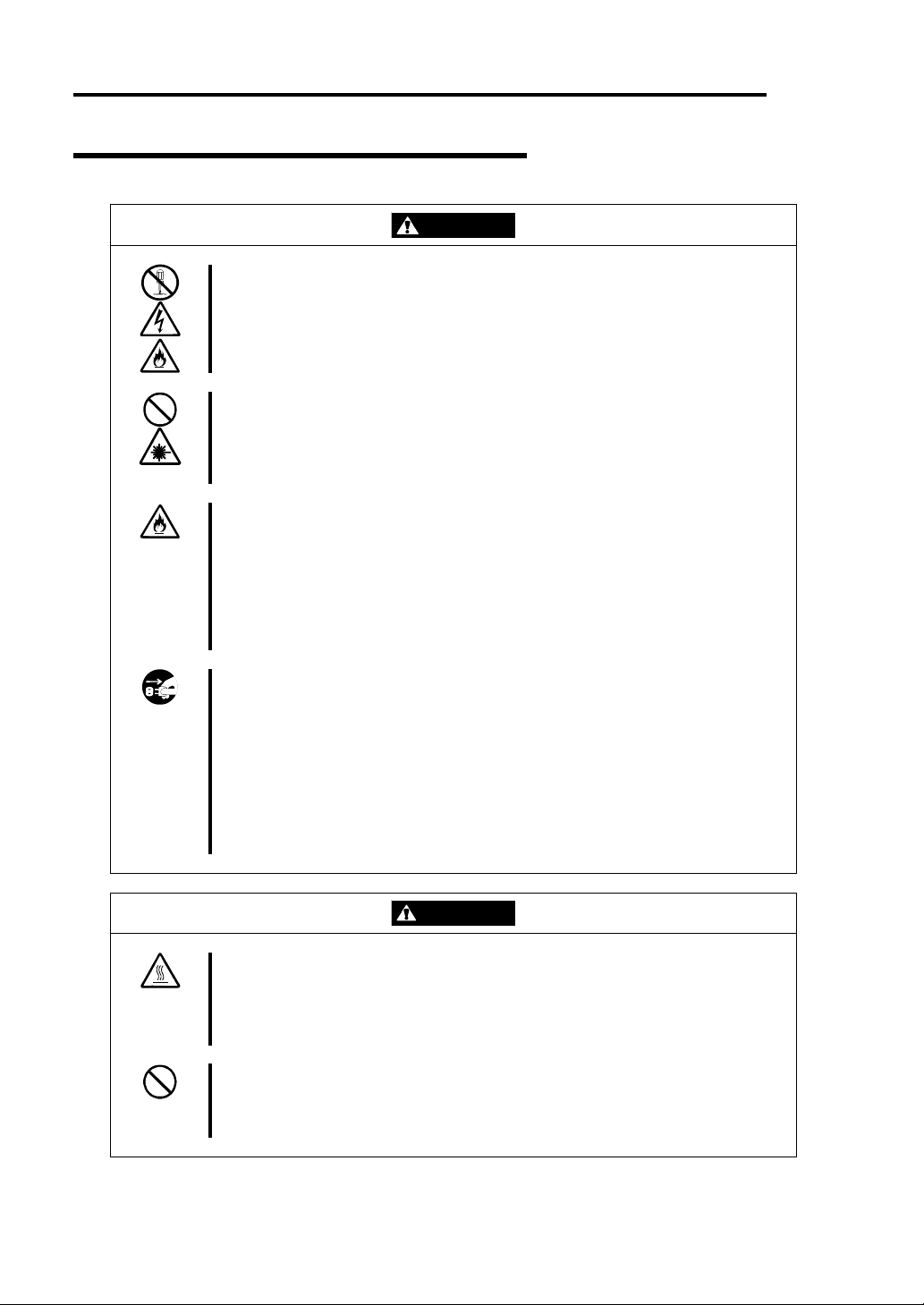
This guide uses the following three types of symbols to give indications and precautions against a
danger. They are defined as follows:
Indicates that a failure to follow the instructions could cause a danger. Each image
symbolizes a particular type of danger. (Attention)
Indicates what you must not do. Each image symbolizes a particular type of
prohibition. (Prohibited actions)
Indicates what you must do. Each image symbolizes a particular type of action
necessary to avoid a danger. (Mandatory actions)
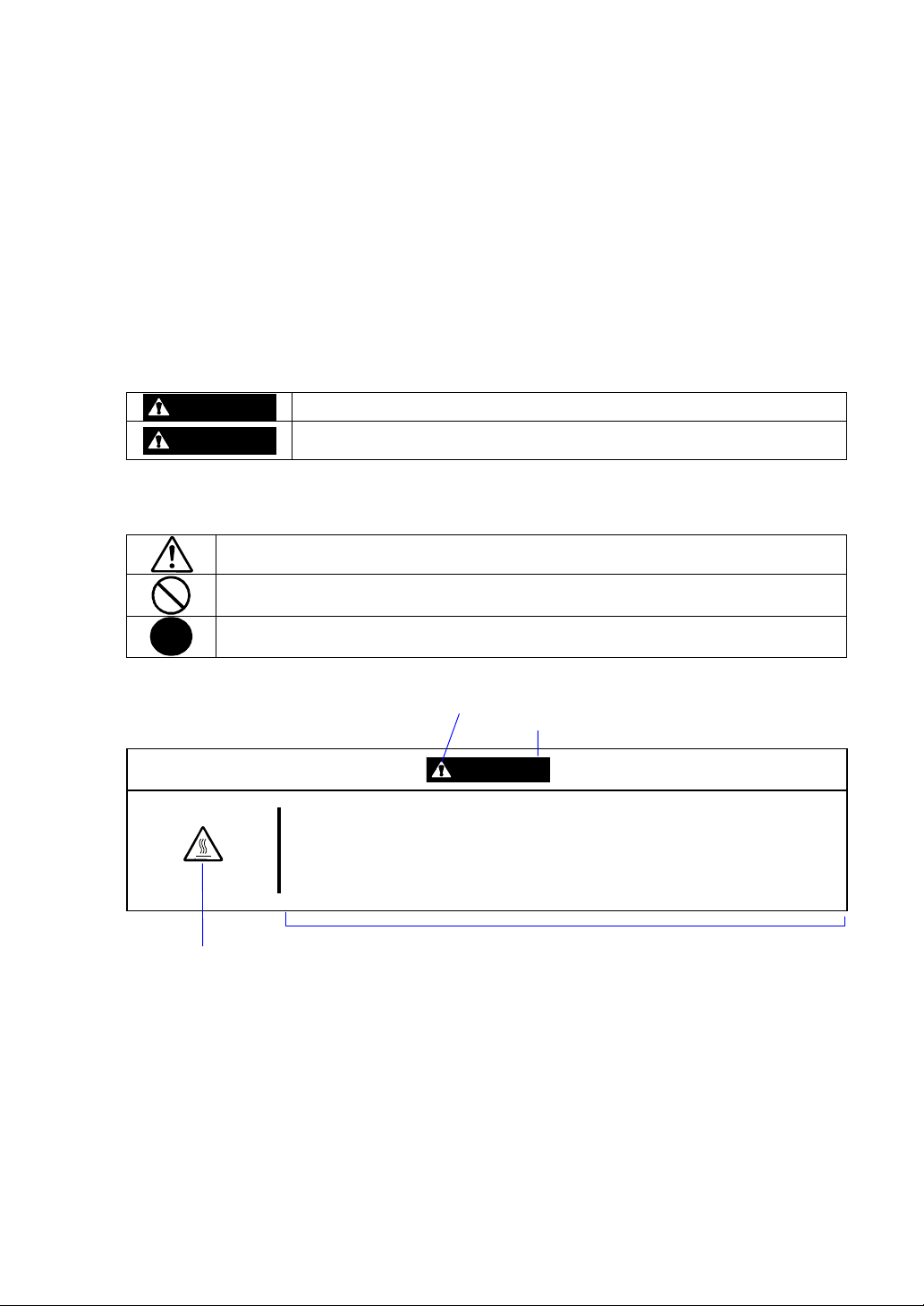
(Example)
High temperature.
Symbol indicating a prohibited
action (may not always be
indicated)
Term indicating a degree of danger
Indicates a danger that could lead to a death or serious injury.
Indicates a danger that could lead to a burn, other injuries or damage to
physical assets.
Symbol to draw attention
CAUTION
Immediately after the power-off, system components such as hard disk are
very hot. Wait the server to cool down completely before adding/removing
some component.
Description of a danger
Page 4
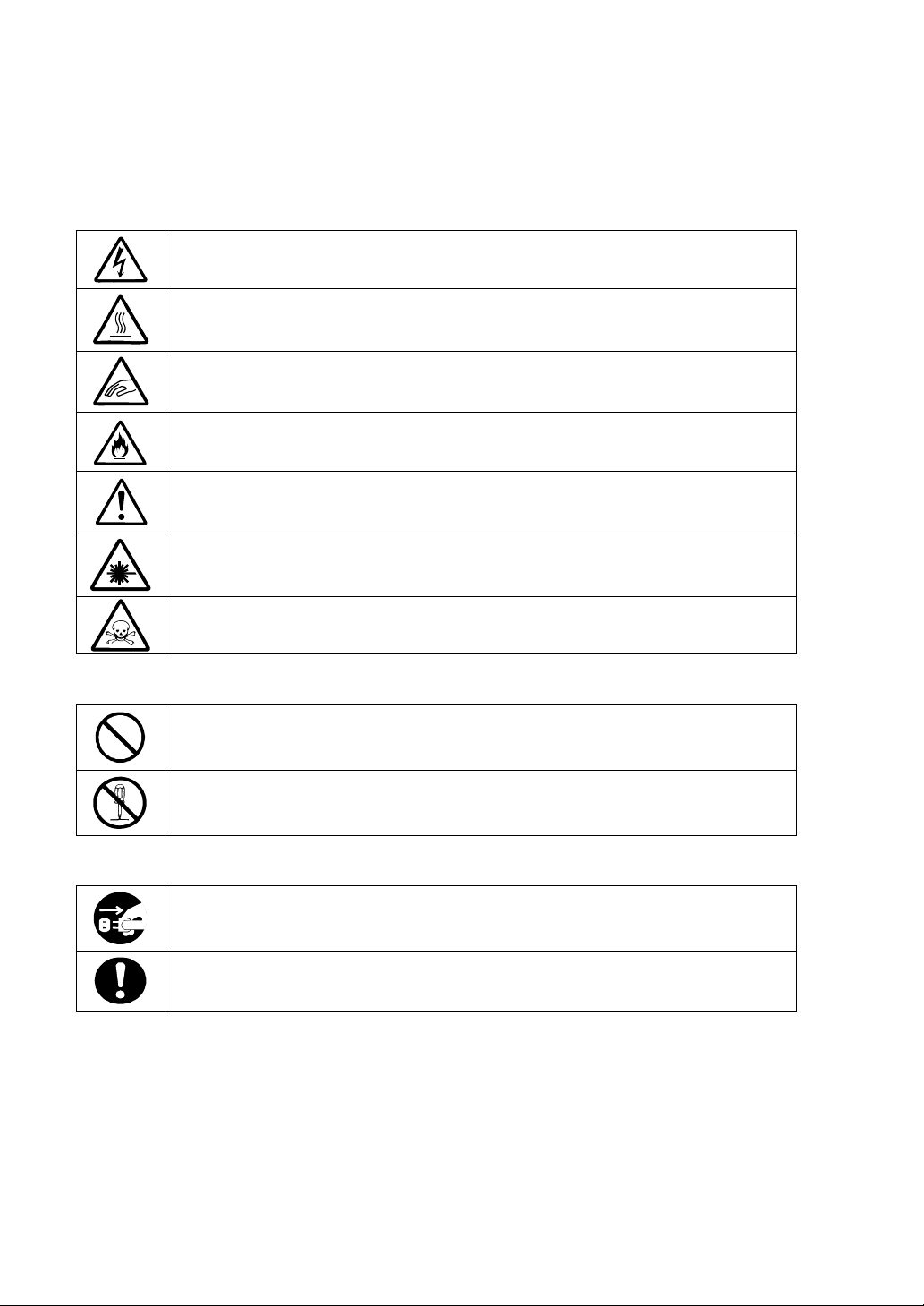
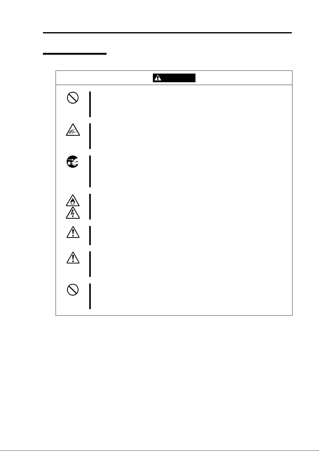
Symbols and its descriptions used in this User’s Guide and warning labels are as follows:
Attention
Indicates a risk of an electric shock.
Indicates a risk of an injury due to heat.
Indicates a risk of catching your fingers.
Indicates a risk of a fire or smoke.
Indicates a general precaution or warning that are not defined herein.
Indicates a risk of losing eyesight due to laser beam.
Indicates a risk of an injury or damage to physical assets due to a hazardous material.
Prohibited actions
Indicates a general prohibition that is not defined herein.
Do not disassemble, repair, or modify the equipment. Otherwise, there is a risk of an
electric shock or fire.
Mandatory actions
Unplug the server. Otherwise, there is a risk of an electric shock or fire.
Indicates a general action to take that is not defined herein. Make sure to follow the
instructions.
For detailed notes to set up the machine safely, refer to “NOTES FOR SAFE HANDLING” on page
1-2.
Page 5

NOTE: This equipment has been tested and found to comply with the limits for a Class A digital
device, pursuant to Part 15 of the FCC Rules. These limits are designed to provide reasonable
protection against harmful interference when the equipment is operated in a commercial
environment. This equipment generates, uses, and can radiate radio frequency energy and, if not
installed and used in accordance with the instruction manual, may cause harmful interference to
radio communications. Operation of this equipment in a residential area is likely to cause harmful
interference in which case the user will be required to correct the interference at his own expense.
This class A digital apparatus meets all requirements of the Canadian Interference-Causing
Equipment Regulations.
Cet appareil numériqeu de la classe A respecte toutes les exigences du Règlement sur le matériel
brouilleur du Canada.
CE Statement
Warning: This is a Class A product. In residential environment, this product may cause radio
interference, in which case the user may be required to take adequate measures (EN55022).
NOTE: This product provides resistance against hardware faults with its redundant hardware
modules. However, this does not mean complete fault-tolerance is assured. For example,
there is a risk of system down when:
– A fatal fault occurs in software.
– Both modules within a redundant hardware pair break down.
– A fatal fault occurs in a non-redundant component, such as the clock generator circuitry
or the interconnect backplane.
– The entire system is cut off from AC power.
Page 6

Trademarks
NEC EXPRESSBUILDER, NEC ESMPRO, and NEC Express5800/ft series are trademarks of NEC
Corporation.
Stratus is a registered trademark of Stratus Technologies Bermuda Ltd.
Microsoft, Windows, Windows Server, Windows NT, and MS-DOS are registered trademarks of
Microsoft Corporation in the United States and other countries.
Intel and Pentium are registered trademarks of Intel Corporation.
AT is a registered trademark of International Business Machines Corporation in the United States
and other countries.
VERITAS is a registered trademark of VERITAS Software Corporation in the U.S. and other
countries.
The VERITAS logo and VERITAS Volume Manager are trademarks of VERITAS Software
Corporation.
Adobe, the Adobe logo, Acrobat, and the Acrobat logo are trademarks of Adobe Systems
Incorporated.
Datalight is a registered trademark of Datalight, Inc. ROM-DOS is a trademark of Datalight, Inc.
Xeon is a trademark of Intel Corporation in the United States. DLT and DLTtape are trademarks of
Quantum Corporation in the United States. QLogic and its logo are trademarks of QLogic
Corporation in the United States. Fast!UTIL is a trademark of QLogic Corporation in the United
States.
All other product, brand, or trade names used in this publication are the trademarks or registered
trademarks of their respective trademark owners.
Microsoft Windows Server 2003 Standard Edition operating system and Microsoft Windows Server
2003 Enterprise Edition operating system are called Windows Server 2003 for short. Microsoft
Windows 2000 Server operating system, Microsoft Windows 2000 Advanced Server operatin g
system and Microsoft Windows 2000 Professional operating system are called Windows 2000 for
short. Microsoft Windows NT Server network operating system version 3.51/4.0 and Microsoft
Windows NT Workstation operating system version 3.51/4.0 are called Windows NT for short.
Microsoft Windows Millennium Edition Operating System is called Windows Me for short.
Microsoft Windows 98 operating system is called Windows 98 for short. Microsoft Windows 95
operating system is called Windows 95 for short.
Names used with sample applications are all fictitious. They are unrelated to any existing product
names, names of organizations, or individual names.
Notes:
(1) No part of this manual may be reproduced in any form without prior written permission of
NEC Corporation.
(2) The contents of this manual are subject to change without prior notice.
(3) The contents of this manual shall not be copied or altered without prior written permission of
NEC Corporation.
Page 7

(4) All efforts have been made to ensure the accuracy of all information in this manual. If you find
any part unclear, incorrect, or omitted in this manual, contact the sales agent where you
purchased this product.
(5) NEC assumes no liability arising from the use of this product, nor any liability for incidental or
consequential damage arising from the use of this manual regardless of (4) above.
PREFACE
Welcome to the NEC Express5800/ft series.
NEC Express5800/ft series is a “fault-tolerant (ft)” server focusing on “high reliability” in terms of
fault-tolerance, in addition to “high performance,” “scalability,” and “general versatility” provided
by NEC Express5800 series. In the event of trouble, its dual configuration will allow the system to
instantaneously isolate the failed parts to assure non-stop running; operation will be moved
smoothly from one module to the other, minimizing damage to it. You can use this ft series in a
mission-critical system where high availability is required. By the use of Windows 2003 operating
system, it also provides outstanding openness for general-purpose applications, etc.
To make the best use of these features, read this User's Guide thoroughly to understand how to
operate NEC Express5800/ft series.
Page 8

ii
ABOUT THIS USER'S GUIDE
This User's Guide helps a user to properly setup and use the product. Consult this guide when you
set up the product.
Keep this manual and the separate volume of User’s guide handy.
This User's Guide is intended for users who have a goo d kn owl e dge on the basic use of Wi nd ow s
operating systems and general I/O devices such as a keyboard and mouse.
How to Use This User's Guide
This guide explains the procedures you should perform before you begin system operation after you
purchased the product. Read the guide in order from Chapter 1. If you perform procedures
according to this guide, you will set up the product properly.
Chapter 3 describes how to install the operating system. Chapter 4 describes post-installa t i on
procedures. Chapter 5 explains how to troubleshoot if you canno t set up the product properly. Refer
to “SYSTEM REPAIR” on page 5-2 for details about system configurations and repairs of this
product. Refer to “TROUBLESHOOTING” on page 5-21 if you feel you failed to set up the
product.
See this User’s Guide for details of this product’s operation, and functions and operations of the
hardware and system.
Page 9

Additional symbols
The following symbols are used throughout this User's Guide in addition to the caution symbols
describe at the beginning.
iii
IMPORTANT:
CHECK:
TIPS:
Important points or instructions to keep in mind when using the
server or software
Something you need to make sure when using the server of
software
Helpful information, something useful to know
Page 10

iv
Page 11

CONTENTS
SAFETY INDICATIONS................................................................................................................iii
PREFACE........................................................................................................................................vii
ABOUT THIS USER'S GUIDE.......................................................................................................ii
CONTENTS.......................................................................................................................................v
CHAPTER 1 BEFORE STARTING SETUP.....................................................................1-1
NOTES FOR SAFE HANDLING.................................................................................................1-2
Tower Model...............................................................................................................................1-2
Rack-mount Model......................................................................................................................1-4
PCI/CPU Modules.......................................................................................................................1-6
PRECAUTIONS FOR SAFETY ..................................................................................................1-7
General ........................................................................................................................................1-7
Use of Power Supply and Power Cord........................................................................................1-9
Installation, Relocation, Storage and Connection......................................................................1-10
Cleaning and Handling of Internal Devices...............................................................................1-12
During Operation.......................................................................................................................1-13
Rack-mount Model....................................................................................................................1-14
v
UNPACKAGING.........................................................................................................................1-15
Accessories................................................................................................................................1-15
Main unit ...................................................................................................................................1-15
CHAPTER 2 SETUP........................................................................................................2-1
INSTALLATION...........................................................................................................................2-2
Tower Model...............................................................................................................................2-2
Installation of Rack-mount Model...............................................................................................2-5
Connection...................................................................................................................................2-8
CHAPTER 3 WINDOWS SETUP.....................................................................................3-1
SWITCHING BOOT MONITORING FUNCTION ~CHANGING BIOS SETTINGS~........3-2
INSTALLING Windows Server 2003 ..........................................................................................3-7
Setup Flow...................................................................................................................................3-9
SETTING DUAL LAN CONFIGURATION.............................................................................3-28
SETTING DUAL DISK CONFIGURATION...........................................................................3-30
Page 12

vi
SWITCHING BOOT MONITORING FUNCTION.................................................................3-33
CHAPTER 4 PROCEDURES AFTER COMPLETION OF INSTALLA TION................... 4-1
SETUP FOR FAILURE MANAGEMENT..................................................................................4-2
Setting Memory Dump (Debug Information)..............................................................................4-2
Setting Dr. Watson.......................................................................................................................4-6
Installing a Network Monitor.......................................................................................................4-7
INSTALLING MANAGEMENT UTILITIES............................................................................4-8
NEC ESMPRO Agent..................................................................................................................4-8
NEC ESMPRO Manager ...........................................................................................................4-18
NEC MWA................................................................................................................................4-18
BACKUP OF SYSTEM INFORMATION.................................................................................4-20
SETTING UP PCS ON A NETWORK......................................................................................4-21
CONFIRMATION OF THE ft CONTROL SOFTWARE VERSION....................................4-23
CHAPTER 5 TROUBLESHOOTING............................................................................... 5-1
SYSTEM REPAIR.........................................................................................................................5-2
Preparation.................................................................................................................................5-2
Starting up Recovery Console...................................................................................................5-4
Updating the System..................................................................................................................5-9
TROUBLESHOOTING...............................................................................................................5-17
Problems with NEC EXPRESSBUILDER............................................................................5-17
Problems with NEC Express5800 ft series Setup ......................................................................5-18
Page 13

Chapter 1
Before Starting Setup
This chapter includes information necessary for proper and safe operation of the server, the main
unit and its accessories. Go through this chapter before you start setup of the produ ct.
Page 14
1-2 Before Starting Setup
NOTES FOR SAFE HANDLING
The following section describes necessary information to use the product properly and safely.
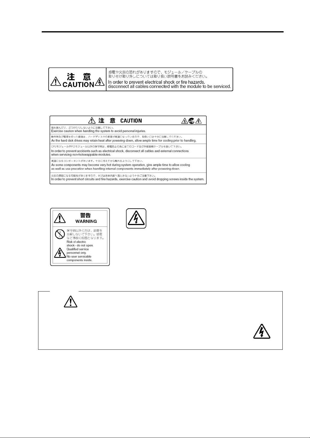
Warning Labels
Warning labels are placed in certain parts of the system so that the user stays alert to possible risks
(Do not remove or damage these labels).
If some label is missing, about to peel off, or illegible, contact your sales agent.
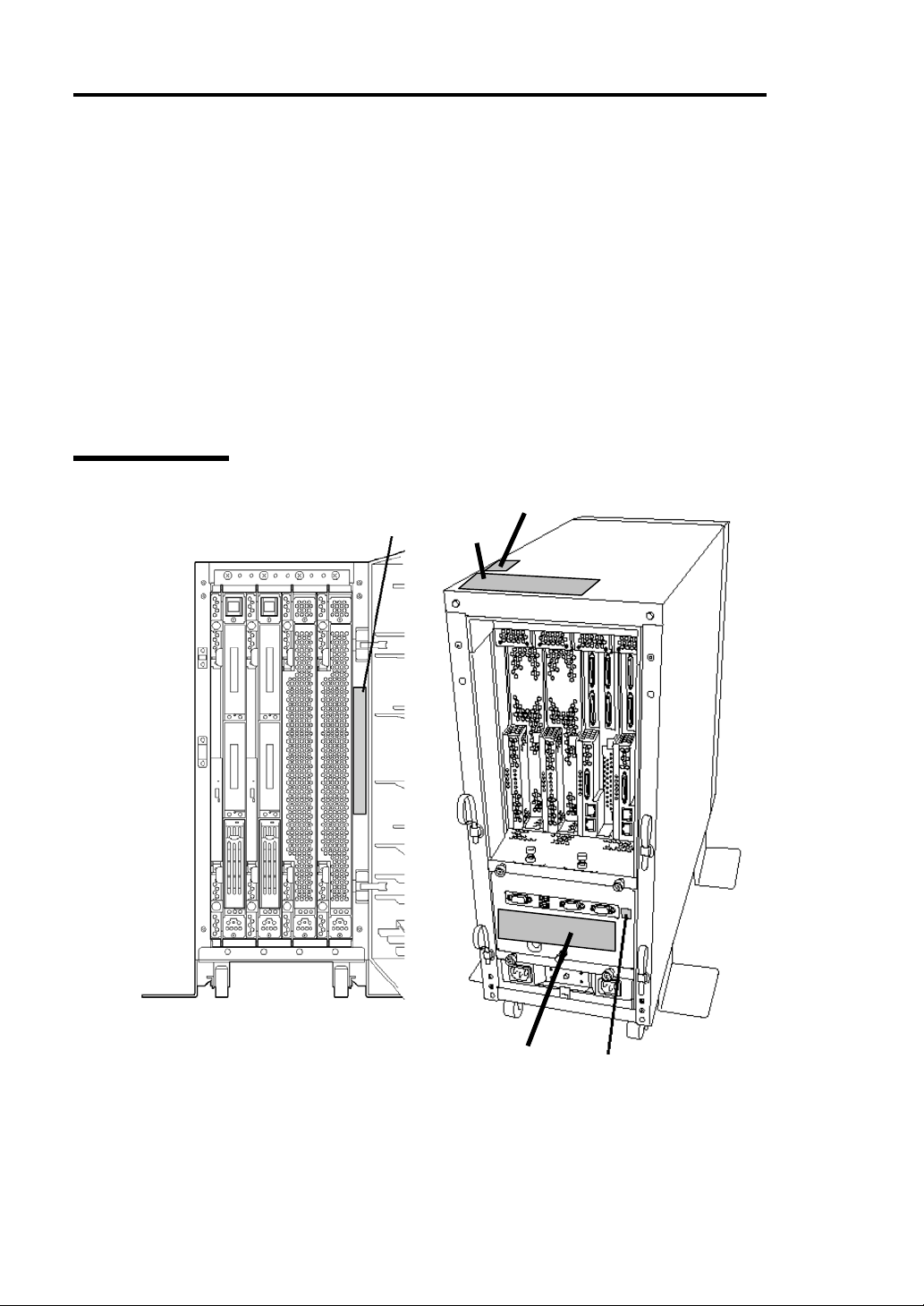
The figures below show locations of the labels on tower model and rack-mount model servers.
Tower Model
Label C
Label A
Label B
Label C
Label D
Label B
Label E
Label E
Label D
Page 15
Before Starting Setup 1-3
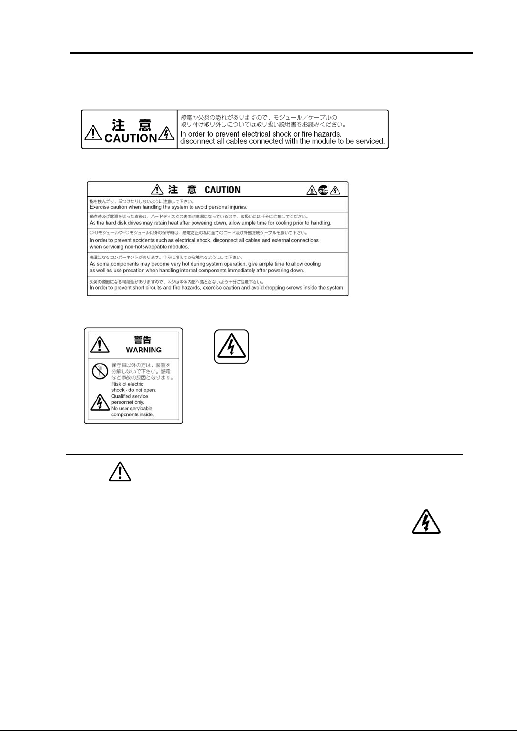
Label A
Label B
Label C Label D
Label E
CAUTION
This unit uses multiple power supply cords.
Disconnect all power supply cords prior to
Servicing this system
Page 16
1-4 Before Starting Setup
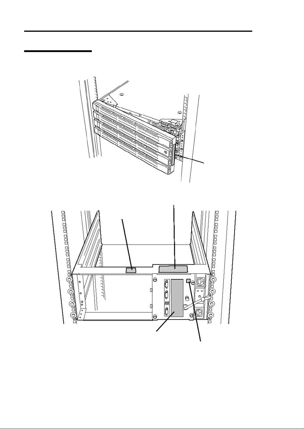
Rack-mount Model
Label A
Label C
Label B
Label E
Label D
Page 17
Label A
Label B
Label C Label D
Label E
Before Starting Setup 1-5
CAUTION
This unit uses multiple power supply cords.
Disconnect all power supply cords prior to
Servicing this system
Page 18
1-6 Before Starting Setup
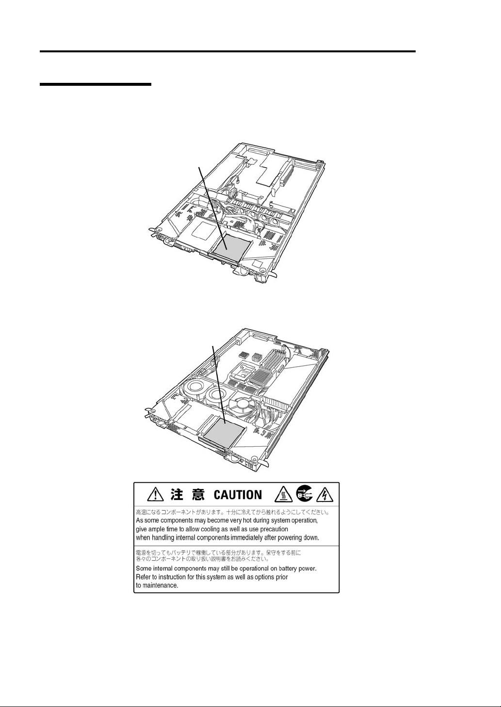
PCI/CPU Modules
PCI Module
CPU Module
Label A
Label A
Label A
Page 19
Before Starting Setup 1-7
PRECAUTIONS FOR SAFETY
This section provides precautions for using the server safely. Read this section carefully to ensure
proper and safe use of the server. For symbol meanings, see "SAFETY INDICATIONS" described
in the previous section.
General
WARNING
Do not use the equipment in an operation where human lives are involved or
high reliability is required.
This equipment is not intended for use in controlling or use with facilities or
systems where human lives are involved or high reliability is required, inc luding
medical devices or nuclear, aerospace, transportation, and traffic control
facilities. NEC assumes no liability for any accidents or damage to physical
assets resulting from the use of this equipment in such systems or facilities.
Do not continue to use the equipment if you detect smoke, odor, or noise.
If the equipment emits smoke, odor, or noise, immediately flip off the POWER
switch, unplug the cord, and contact your sales agent. There is a risk of a fire.
Do not insert a wire or metal object.
Do not insert a wire or metal objects into a vent or disk drive slot. There is a risk
of an electric shock.
Do not use the equipment in an unsuitable place.
Do not install a server rack in an unsuitable environment.
Otherwise, other systems also may be affected, and the rack may fall over to
cause a fire or injuries. For details about installation environment and
quake-resistant engineering, see the attached manual or contact you sales
agent.
Do not install the equipment on a nonconforming rack.
Install the equipment on a 19-inch rack confirming to the EIA standard. Do not
use the equipment without a rack or install it on a nonconforming rack.
Otherwise, the equipment may not function properly, and there is a risk of
damage to physical assets or injuries. For suitable racks, contact your sales
agent.
Page 20
1-8 Before Starting Setup
Prevent water or foreign objects from getting into the equipment.
Do not let water or foreign objects (e.g., pins or paper clips) enter the
equipment. There is a risk of a fire, electric shock, and breakdown. When such
things accidentally enter the equipment, immediately turn off the power and
unplug the cord. Contact your sales agent instead of trying to disassemble it
yourself.
Do not touch any damaged LCD.
The LCD on the server front contains a liquid harmful to the human body. If the
liquid leaked from the LCD accidentally gets in your mouth, immediately gargle
and see a doctor. If it accidentally gets on your skin or in your eye, rinse it with
water immediately for at least 15 minutes.
CAUTION
Page 21
Use of Power Supply and Power Cord
Before Starting Setup 1-9
WARNING
Do not handle a power plug with a wet hand.
Do not plug/unplug a power cord with a wet hand. There is a risk of an electric
shock.
Do not connect the ground wire to a gas pipe.
Never connect the ground wire to a gas pipe. There is a risk of a gas explosion.
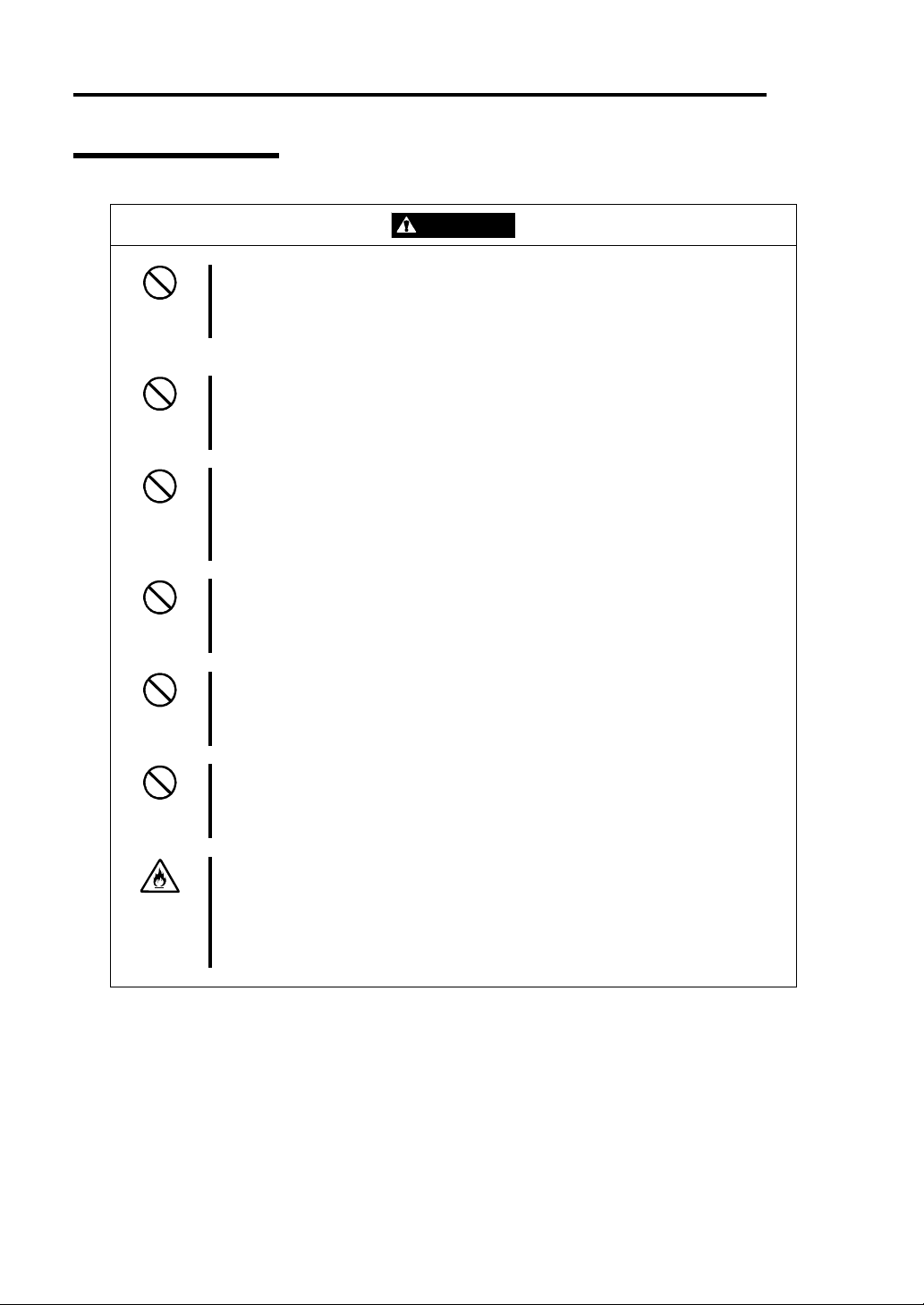
CAUTION
Do not plug the cord in a nonconforming outlet.
Use a wall outlet with specified voltage and power type. Otherwise, there is a
risk of a fire or current leakage.
Avoid installing the equipment where you may need an extension c ord. If the
cord that does not meet the power specifications, there is a risk of overheating
that could lead to a fire.
Do not plug too many cords in a single outlet.
If the rated current is exceeded, there is a risk of overheating that could lead to
a fire.
Do not plug the cord insecurely.
Insert the plug firmly into an outlet. Otherwise, there is a risk of heat or fire due
to poor contact. If dust settles on the slots and it absorbs moisture, there is also
risk of heat or fire. a
Do not use nonconforming power cords.
Use only the power cords that come with the product. If the rated current is
exceeded, there is a risk of a fire.
You also have to observe the following prohibitions to prevent damage to the
cords.
Do not pull on the cord.
Do not pinch the cord.
Do not bend the cord.
Keep chemicals away from the cord.
Do not twist the cord.
Do not place any object on the cord.
Do not bundle several cords.
Do not alter, modify, or repair the cord.
Do not staple the cord.
Do not use any damaged cord. (Replace it with a new one of the same
specifications. For replacement procedures, contact your sales agent.)
Page 22
1-10 Before Starting Setup
Installation, Relocation, Storage and Connection
WARNING
Disconnect the power cord(s) before installing or removing the equipment.
Be sure to power off the equipment and unplug its power cords from the wall
outlet before installation/relocation. All voltage is removed only when the power
cords are unplugged.
Do not hold the front bezel to lift the equipment.
The equipment weighs around 70 kg (depending on its hardware configuration).
Do not hold the front bezel, or it may become detached, causing an injury. For
lifting and moving the equipment, remove the mounted modules from the main
unit and carry them separately. It takes at least two people to carry it; hold the
equipment firmly by its bottom.
Do not install the equipment in an unsuitable place.
Install the equipment in such a place as specified in this User's Guide. Avoid
the following, or there is a risk of a fire.
a dusty place
a humid place located near a boiler, etc
a place exposed to direct sunlight
an unstable place
Be careful not to hurt your fingers.
Exercise great care not to hurt your fingers on the rail when you
mount/dismount the equipment into/from the rack.
CAUTION
Page 23
Before Starting Setup 1-11
Do not connect any interface cable with the power cord of the server plugged to
a power source.
Make sure to power off the server and unplug the power cord from a power
outlet before installing/removing any optional internal device or
connecting/disconnecting any interface cable to/from the server. If the server is
off-powered but its power cord is plugged to a power source, touching an
internal device, cable, or connector may cause an electric shock or a fire
resulted from a short circuit.
Do not use any non-designated interface cable.
Use only interface cables designated by NEC; identify which component or
connector to attach beforehand. If you use a wrong cable or make a wrong
connection, there is a risk of short-circuit that could lead to a fire.
You also have to observe the following prohibitions about handling and
connecting interface cables:
Do not use any damaged cable connector.
Do not step on the cable.
Do not place any object on the cable.
Do not use the equipment with loose cable connections.
CAUTION
Page 24
1-12 Before Starting Setup
Cleaning and Handling of Internal Devices
WARNING
Do not disassemble, repair, or alter the server.
Unless described herein, never attempt to disassemble, repair, or alter the
equipment. There is a risk of an electric shock or fire as well as malfunction.
Do not look into the CD-ROM drive
The CD-ROM drive uses a laser beam. Do not look or insert a mirror inside
while the system is on. A laser beam is invisible; if your eyes get exposed to it,
there is a risk of losing eyesight.
Do not detach a lithium battery yourself.
This equipment has a lithium battery. Do not detach it yourself. If the battery is
exposed to fire or water, it could explode.
When the lithium battery is running down and the equipment doesn’t work
correctly, contact your sales agent instead of disassembling, replacing or
recharging it yourself.
Disconnect the power plug before cleaning the server.
Make sure to power off the server and disconnect the power plug from a power
outlet before cleaning or installing/removing internal optional devices. Touching
any internal device of the server with its power cord connected to a power
source may cause an electric shock even of the server is off-powered.
Disconnect the power plug from the outlet occasionally and clean the plug with
a dry cloth. Heat will be generated if condensation is formed on a dusty plug,
which may cause a fire.
High temperature
Immediately after powering off the system, system components such as hard
disk may be very hot. Wait for the server to cool down completely before
adding/removing components.
Make sure to complete installation.
Firmly install all power cords, interface cables and/or boards. An incompletely
installed component may cause a contact failure, resulting in fire and/or smoke.
CAUTION
Page 25
During Operation
Before Starting Setup 1-13
Do not pull out a device during operation.
Do not pull out or remove a device while it works. There is a risk of malfunction
and injuries.
Do not touch the fan.
While the equipment is on, be careful not to get your fingers or hair caught in
the cooling fan that is located in the back.
Do not touch the equipment when it thunders.
Unplug the equipment when it threatens to thunder. If it starts to thunder before
you unplug the equipment, do not touch the equipment and cables. There is a
risk of a fire or electric shock.
Keep animals away.
Animal’s waste or hair may get inside the equipment to cause a fire or electric
shock.
Do not place any object on top of the server.
The server may fall down to cause damage to physical assets.
Do not leave the CD tray ejected.
Dust may get in the equipment to cause malfunction. The ejected tray may also
become a cause of injuries.
Do not use a cellular phone or pager around the equipment.
Turn off your cellular phone or pager when you use the equipment. Their radio
waves may cause the equipment to malfunction.
CAUTION
Page 26
1-14 Before Starting Setup
Rack-mount Model
CAUTION
Do not attempt to install the server yourself.
To avoid a risk of injuries, users should not attempt to install the equipment into
a rack. Installation should be performed by trained maintenance personnel.
< For Maintenance Personnel Only >
Do not remove and carry the equipment with modules mounted.
When you remove this product from the rack and carry it, remove all modules
that are mounted first.
Do not install the equipment in such a manner that its weight is imposed on a
single place.
To distribute the weight, attach stabilizers or install two or more racks.
Otherwise, it may fall down to cause injuries.
Do not assemble parts alone.
It takes at least two people to mount doors and trays to a rack. Otherwise, you
may drop some parts to cause a breakage or injuries.
Do not pull a device out of the rack if it is unstable.
Before pulling out a device, make sure that the rack is fixed (by stabilizers or
quake-resistant engineering).
Do not leave two or more devices pulled out from the rack.
If you pull out two or more devices the rack may fall down. You can only pull out
one device at a time.
Do not install excessive wiring.
To prevent burns, fires, and damage to the equipment, make sure that the rated
load of the power branch circuit is not exceeded. For more information on
installation and wiring of power-related facilities, contact your electrician or local
power company.
Page 27

Before Starting Setup 1-15
UNPACKAGING
The following section describes necessary information to use the product properly and safely.
Accessories
This product is shipped with various accessories. See the attached list to make sure everything is
included and check the individual items. If some component is missing or damaged, contact your
sales agent.
Keep the accessories in a safe place. You will need them when you perform setup,
addition of options, or replacement of failed components.
To check NEC EXPRESSBUILDER components, see the attached list.
Be sure to fill out and mail the software registration card that is attached to your operating
system.
Make backup copies of included floppy disks, if any. Keep the origin al disks as the master
disks; use these copies in operation.
Improper use of an included floppy disk or CD-ROM may alter your system environment.
If you find something unclear, stop using them and contact your sales agent.
Main unit
Confirm the followings after you unpack the product
If your product has standard configurations, before you set up the main unit, attach
optional memory and CPU (for models which support additional CPUs) that you
purchased separately. See the separate volume of User’s Guide for details.
If your product has custom configurations of “build-to-order”, confirm that all optional
items you specified are installed.
Page 28

1-16 Before Starting Setup
Page 29

Chapter 2
Setup
This chapter describes the requirements to use the product properly and safely, the setup procedures
to make NEC Express5800/ft series ready for use, and ho w t o con nect peripherals.
Page 30
2-2 Setup
INSTALLATION
This section describes installation of NEC Express5800/ft series.
Tower Model
IMPORTANT: NEC Express5800/ft series is a precision instrument. You should ask
maintenance personnel to install it.
Select a suitable site for tower model.
CAUTION
Observe the following instructions to use the equipment safely. Failure to follow
these instructions could cause a burn, injury, or damage to physical assets. For
details, see “NOTES FOR SAFE HANDLING” in Chapter 1.
Remove all modules before moving the equipment.
Do not install the equipment in non-designated places.
Close enough to connect the
mouse and the display.
Floor or a level
and robust desk or
table
Room that can maintain the following
conditions during operation:
Temperature: 10 to 35ºC
Humidity: 20 to 80% (non-condensing)
100V 120 V or 200V - 240
V parallel bi-polar power
outlet with grounding
Wall outlet within the
reach of supplied power
cord.
Clean and tidy room
Place having a space enough to fully open
the front bezel (The front bezel extrudes
about 50 mm from the right side of the
server when fully opened.)
UPS to prevent momentary voltage drop due to power
failure or lightning *
* Optional. UPS is recommended for best use of
features of ft server.
* It is recommendable to use the server in a room where
temperature can be kept between 15 and 25ºC.
Page 31
Setup 2-3
Do not install NEC Express5800/ft series in such places as listed below. Otherwise, the server may
malfunction.
Place where temperatures change widely (near a heater, air conditioner, or refrigerator).
Place that is subject to intense vibration.
Place where corrosive gas (sodium chloride, sulfur dioxide, hydrogen sulfide, nitrogen
dioxide, or ozone)
is generated, or a place that is close to chemicals or exposed to
chemicals.
Place whose floor is covered with non-antistatic carpet.
Place that may be subject to falling objects.
Place where you may step or trip on the power cords or interface cables.
Place that is close to some equipment that generates intense magnetic field (e.g., TV set,
radio, broadcasting/communications antenna, power transmission wire, and
electromagnetic crane). (If unavoidable, contact your sales agent to request proper shield
construction.)
Place where the power cord of the server must be connected to an AC outlet that shares
the outlet of another device with large power consumption.
Place that is close to some equipment that causes power noises (e.g., sparks caused by
power-on/off using a relay). If you must install the server close to such equipment, request
your sales agent for separate power cabling or noise filter installation.
It takes at least two people to carry the server; hold it firmly by its bottom and place it slowly on the
selected site.
IMPORTANT: Do not hold the front bezel to lift it, or it may become detached and fall down.
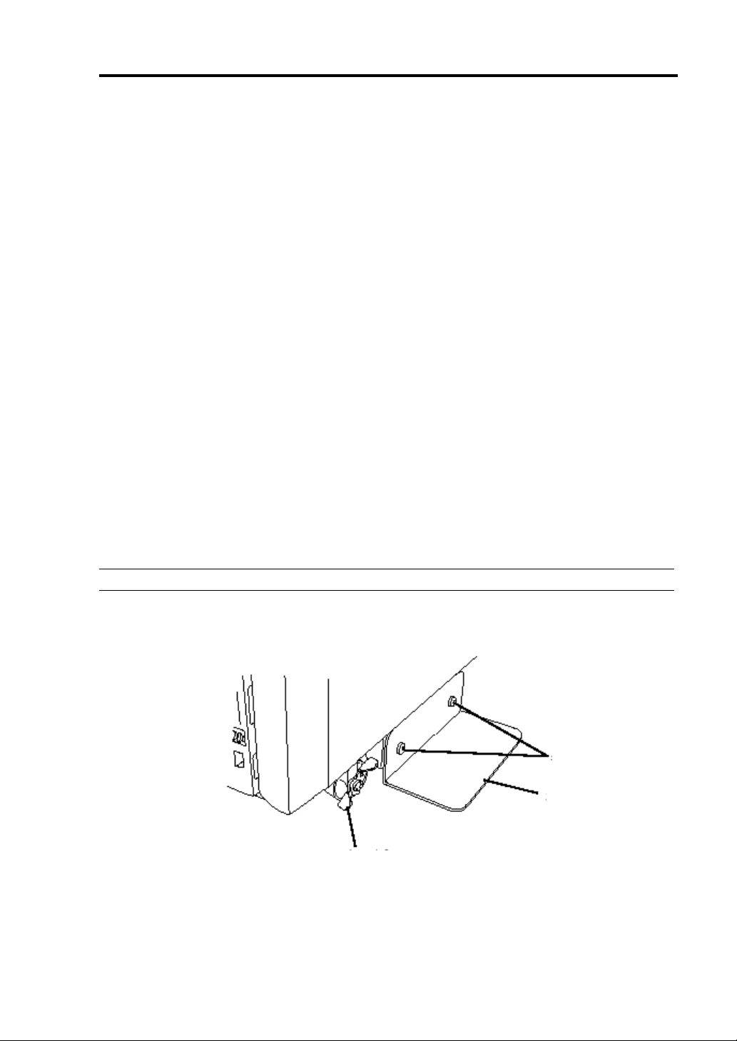
After placing the main cabinet, lock its two front casters and screw the attached four stabilizers on
the cabinet adjusting their height.
Screws
Stabilizer
Lock lever
Page 32

2-4 Setup
After fastening the main cabinet, open its front bezel to mount the CPU and PCI modules. For
details, see the following section “Installation of Rack-mount Model.” Procedures are basically the
same for the tower model except that its modules are mounted vertically instead of horizontally.
IMPORTANT: Follow the procedures below to install the CPU and PCI modules. Note the
followings before installing them.
Confirm the main cabinet is immobilized.
Place removed modules to the side of the system. Do not place modules on top of the system.
It takes at least two people to mount the modules; mount them slowly and carefully.
If you cannot install modules smoothly, remove them and try again.
Install the CPU modules in the left two slots, the PCI modules in the right two slots.
Perform installation from the left slots.
Page 33

Setup 2-5
Installation of Rack-mount Model
You can mount NEC Express5800/ft series on a rack that conforms to the EIA standards.
IMPORTANT: NEC Express5800/ft series is a precision instrument. You should ask maintenance
personnel to install it.
To install a rack, contact your sales agent or maintenance personnel.
CAUTION
Do not attempt to install the server.
To avoid the risk of personal injury, users should not attempt to install the
server into the rack assembly. The server should be installed in the rack only by
trained maintenance personnel.
Room that can maintain the
following conditions during
operation:
Temperature: 10 to 35ºC
Humidity: 20 to 80%
(non-condensing)
100V - 120 V or 200V - 240 V
parallel bi-polar power outlet
with grounding
Wall outlet within the
reach of supplied power
cord.
Space 40 cm or more on top, 1 m or more
on the front and rear, and 60 cm or more on
the right and left.
Level and reinforced
floor.
* It is recommended to use the server in a room where
temperature can be kept between 15 and 25ºC.
Page 34

2-6 Setup
WARNING
Observe the following instructions to use the server safely. Failure to follow
these instructions could lead to a death or serious injury. For details, see
“NOTES FOR SAFE HANDLING” in Chapter 1.
Do not install the equipment in non-designated places.
Do not connect the ground wire to a gas pipe.
Observe the following instructions to use the equipment safely. Failure to follow
these instructions may cause a burn, personal injury, or damage to physical
assets. For details, see “NOTES FOR SAFE HANDLING” in Chapter 1.
Do not carry or install the equipment alone.
Do not install the equipment in such a manner that its weight is imposed on a
single place.
Do not assemble or disassemble parts alone.
Do not pull a device out of the rack if it is unstable.
Do not leave two or more devices pulled out from the rack.
Do not install excessive wiring.
CAUTION
Do not install NEC Express5800/ft series in such places as listed below. Otherwise, the server may
malfunction.
Place where you cannot pull out the components fully.
Place that cannot sustain the total weight of the rack system.
Place where you cannot mount stabilizers or where you cannot perform installation
without quake-resistant engi n eeri n g.
Place whose floor is uneven or inclined.
Place where temperatures change widely (near a heater, air conditioner, or refrigerator).
Place that is subject to intense vibration.
Place where corrosive gas (sodium chloride, sulfur dioxide, hydrogen sulfide, nitrogen
dioxide, or ozone)
is generated, or a place that is close to chemicals or exposed to
chemicals.
Place whose floor is covered with non-antistatic carpet.
Place that may be subject to falling objects.
Place that is close to some equipment that generates intense magnetic field (e.g., TV set,
radio, broadcasting/communications antenna, power transmission wire, and
electromagnetic crane). (If unavoidable, contact your sales agent to request proper shield
construction.)
Place where the power cord of the server must be connected to an AC outlet that shares
Page 35

Setup 2-7
the outlet of another device with large power consumption.
Place that is close to some equipment that causes power noises (e.g., sparks caused by
power-on/off using a relay). If you must install the server close to such equipment, request
your sales agent for separate power cabling or noise filter installation.
IMPORTANT: Temperature increase inside the rack and airflow
If you install several components or the ventilation isn’t good inside the rack, the internal
temperature may increase due to heat emitted from the components. When the operating
temperatures of NEC Express5800/ft series (10° to 35°C) are exceeded, there is a risk of
malfunction. You must take adequate precautions and measures for airflow inside the rack as well
as in the room so that the internal temperature can be kept within thi s ran ge du ri n g o per at i on.
Page 36

2-8 Setup
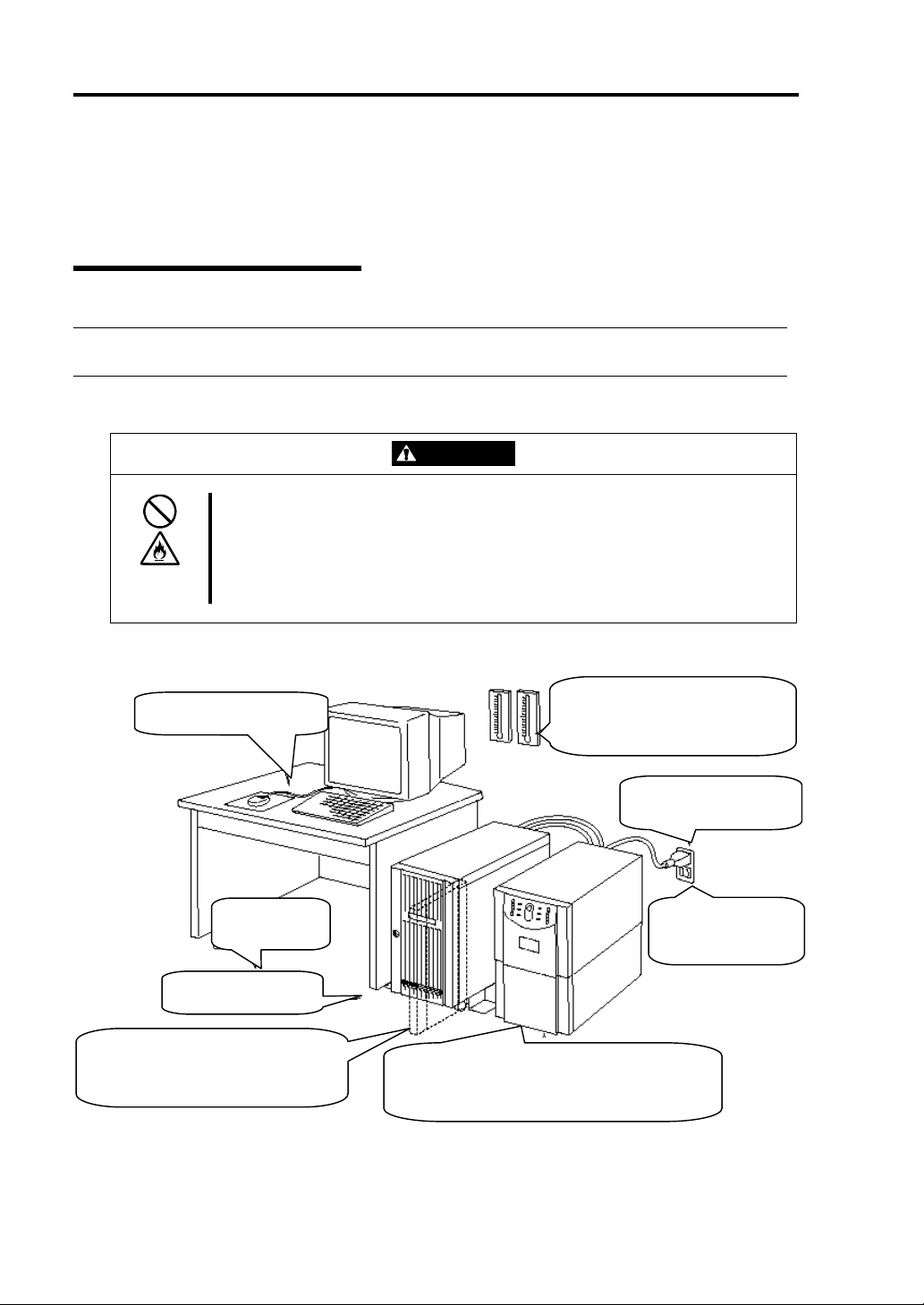
Connection
Connect peripheral devices to NEC Express5800/ft series.
The server is provided with connectors for wide variety of peripheral devices on its front and rear.
The figure below illustrates available peripheral devices for the server in the standard configuration,
and locations of the connectors for the devices. After connecting the peripheral devices, connect the
provided power cord with the server, then plug the power cord into the power outlet.
IMPORTANT:
WARNING
Observe the following instructions to use the server safely. Failure to follow
these instructions could lead to a death or serious injury. For details, see
“NOTES FOR SAFE HANDLING” in Chapter 1.
Do not hold the power plug with a wet hand.
Do not connect the ground wire to a gas pipe.
CAUTION
Observe the following instructions to use the equipment safely. Failure to follow
these instructions may cause a burn, personal injury, or damage to physical
assets. For details, see “NOTES FOR SAFE HANDLING” in Chapter 1.
Do not plug the power cord in a nonconforming outlet.
Do not plug too many cords in a single outlet.
Do not plug the cord insecurely.
Do not use nonconforming power cords.
Power off the server before connecting peripheral devices, with the exception of peripherals
with USB interface. Connecting a powered peripheral device to the powered server will cause
malfunctions and failures.
To connect a third-party peripheral device or interface cable to the server, check with your
sales agent to see if they are compatible with NEC Express5800/ft series. Some third-party
devices may not be used with the server.
The total cable length of SCSI device connections is up to 6 m, including the internal SCSI
cables.
The serial port connectors are reserved for maintenance.
Page 37

Setup 2-9
r
r
A tower model is shown here for convenience of explanation. However, the steps are the same for a
rack-mount model except that its modules are mounted horizontally.
IMPORTANT: Place the USB floppy disk drive on top of the tower cabinet. However, to place it
on a rack-mount model, put a distance of one unit between the disk drive and the module.
To a SCSI
backup device
To a 1000Mbps
network
To a 100Mbps
network
Display
2
1
USB floppy
disk drive
A
B
Reserved fo
maintenance
Reserved fo
maintenance
Keyboard (via keyboard hub to mouse)
IMPORTANT: Connection of optional devices
In the case of standard configuration, you need to complete setup of the operating system
before mounting optional PCI cards or hard disks that you bought separately.
In the case of “Build-to-Order” configurations, if N8803-030 or 031 is mounted, be sure to
connect cables to the additional cabinets before going on to the next steps.
Page 38

2-10 Setup
After connecting cables to PCI modules, secure them with the cable ties.
When completing connection to peripheral equipment, connect the two provided power cords to the
server. After that, secure the cables with the cable tie provided in the server.
Connect the plug at the other end of the power cord to a wall outlet with parallel double-pole
grounds provided or to an uninterruptible power supply (UPS).
To use the functions of the server, you should connect the server to the UPS.
<Tower model>
Power cords
IMPORTANT:
Be sure to use both of the power cords to use ft series functions.
If both PCI modules are mounted, the one you plug in first will become the primary module.
The power connector B is used for Group 1; the power connector A is for Group 2.
The module whose POWER switch LED is on is the primary.
To connect the power cord from the server to an uninterruptible power supply (UPS), use service
outlets on the rear of the UPS.
The UPS service outlets are categorized into two groups: SWITCH OUT and UN-SWITCH OUT.
(They may be called "OUTPUT1" and "OUTPUT2".)
For constant power supply, connect the power cord to a UN-SWITCH OUT outlet. (Connect the
modem that is in service for 24 hours to this outlet.)
When the power cord from the server is connected to a UPS, change the BIOS setup of the server to
link with power supply from the UPS.
Page 39

Setup 2-11
Select [System Hardware] → [AC-LINK] on the BIOS setup utility and change parameters. See the
separate volume of User’s Guide for details.
< Example>
Page 40

2-12 Setup
(This page is intentionally left blank.)
Page 41

Chapter 3
Windows Setup
This chapter describes procedures for switching boot monitoring function, setup, installing Windows,
setting dual LAN configuration, setting dual disk configuration and so on.
Page 42

3-2 Windows Setup
SWITCHING BOOT MONITORING FUNCTION ~CHANGING
BIOS SETTINGS~
Check whether the power is ON and make settings for properly performing setup for later on.
This equipment has a function to monitor the main unit at startup. (Enabled in the configuration at
shipment)
When reinstalling the operating system, this monitoring function needs to be disabled. Otherwise
the installation may not be done properly. Follow the steps in this section and make proper settings.
A rack-mount model is shown here for convenience of explanation. However, the steps are the same
for a tower model except that the modules are mounted vertically.
IMPORTANT: If you skip the settings described here, the system will be restarted forcefully
while Windows setup screen is shown and the setup will be unsuccessful; BIOS may repeat
Windows setup in an invalid manner. In this case, you will need to restart the setup procedures from
the beginning.
TIPS: For details of operations for BIOS Setup Utility and parameters, see the separate volume of
User’s Guide.
1. Turn on the display and the peripheral equipment connected to the NEC Express5800/ft series.
CHECK: If the power cord is connected to a power controller like a UPS, make sure that it is
powered on.
TIPS: When the AC power of the NEC Express5800/ft series is turned on, after the power is
supplied, BMC is synchronized between the PCI modules. Upon the completion of the BMC
synchronization, the POWER lamp of either PCI module will be lit.
2. Open the front bezel (or detach it in the case of a rack-mount model).
3. Confirm that the BMC status lamp (
POWER switch which is located on the front panel.
) on both PCI modules is off and press the illuminated
Page 43

BMC status lamp
Windows Setup 3-3
PCI modules CPU modules P OWER swit che s*
* Only the lit POWER switch can be used.
IMPORTANT:
Do not turn off the power before the "NEC" logo appears.
When powering on, make sure that the BMC status lamp (
are off and then press the power switch.
After a while, the "NEC" logo will appear on the screen.
While the "NEC" logo is displayed on the screen, NEC Express5800/ft series is performing a
power-on self test (POST) to check itself. For details, see the separate volume of User’s Guide.
Upon the completion of POST, Windows will start.
) on the both PCI modules
CHECK: If the server finds errors during POST, it will interrupt POST and display the error
message. See the separate volume of User’s Guide.
Page 44

3-4 Windows Setup
4. When the message “Press <F2> to enter SETUP” or “Press <F2> to enter SETUP or Press
<F12> to Network” on the display screen, press F2.
The BIOS Setup Utility “SETUP” starts and the Main menu is displayed on the screen.
5. Move the cursor onto "Advanced" and select “Advanced”.
The Advanced menu will be displayed.
Page 45

6. Move the cursor onto “Monitoring Configuration” and press Enter.
The Monitoring Configuration submenu appears.
Windows Setup 3-5
7. Move the cursor onto “Boot Monitoring” and press Enter.
Parameters will be displayed.
8. Among the parameters, choose “Disable” and press Enter.
The current display of the configuration for Boot Monitoring will be changed to “Disabled”.
Page 46

3-6 Windows Setup
9. Move the cursor onto "Exit" to display the Exit menu.
10. Move the cursor onto “Save Changes & Exit” and press Enter.
The confirmation window will appear.
11. Select “Yes” and press Enter.
After the configuration data is saved and SETUP is terminated, the system is rebooted.
This is the end of steps for switching boot monitoring function.
TIPS: When reinstalling the OS, power off this equipment to prepare for reinstallation. Then,
referring to page 3-7 “INSTALLING Windows Server 2003” and continue the setup.
Page 47

Windows Setup 3-7
INSTALLING Windows Server 2003
Use NEC EXPRESSBUILDER to setup the NEC Express5800/ft series.
IMPORTANT: The NEC Express5800/ft series is a precision instrument. You should ask
maintenance personnel to install it.
The ft series setup program is exclusively used for the NEC Express5800/ft series. To execute the
setup program, simply select the item [Setup] from the menu displayed when starting the system
through the provided CD-ROM "NEC EXPRESSBUILDER.” The setup program automatically
performs the complete setups from hardware internal parameter/status settings to installation of the
operating system (Windows Server 2003) and various utilities.
Use the ft series setup program for the first installation and reinstallation of the operating system. This
program accomplishes complicate setups.
Before performing ft series setup, contact your sales agent about the latest release of ft control
software.
About OS installation
Read the notes here carefully before installing the operating system.
Operating System Supported by the NEC Express5800/ft series
NEC Express5800/ft series supports the operating system, Microsoft® Windows® Server 2003
Enterprise Edition (English) (hereinafter called "Windows Server 2003 ").
NEC Express5800/ft series does not support any operating systems (e.g., Windows Server 2003
Standard Edition, Windows 2000 Server or Windows NT 4.0) other than the above.
About Windows Server 2003
Use the ft series setup program to install Windows Server 2003. Note the following at installation:
IMPORTANT:
• Complete all the setups such as the memory expansion and BIOS setting before installing
Windows Server 2003.
• NEC software package, which is to be purchased separately, is also provided with the
documentation for installation. However, see this User's Guide for installation into this server.
• After completing the ft series setup program, make settings for failure management (e.g.,
memory dump (debug information) setting) according to Chapter 4.
Page 48

3-8 Windows Setup
Size of the Partition to be Created
The required minimum size of a partition to install the system can be obtained from the following
formula:
Size required for installation + paging file size + dump file size
Size required for installation = 2,900MB
Paging file size (recommended) = size of memory mounted* × 1.5
Dump file size = size of memory mounted* + 12MB
IMPORTANT:
The above paging file size is necessary for collecting debug information (memory dump). If a
value smaller than the “Recommended” value is set for the initial size of the paging file, correct
debug information (memory dump) may not be collected.
The maximum paging file size is 4095MB in a partition. If 1.5 tines the size of mounted
memory is larger than 4095MB, set the size at 4095MB.
If the size of mounted memory is larger than 2GB, the maximum size of dump file is
“2048MB+12MB.”
TIPS: The mounted memory size means the total of memory installed on a single CPU module.
For example, if memory of 512MB is mounted, the required minimum partition size obtained from
the above formula is as follows:
2900MB +(512MB × 1.5)+(512MB +12MB)=4192MB
TIPS: In the case of ft series setup, you need to create a partition of 3072MB or more to perform
auto installation.
About Auto Installation of Utilities
The ft series setup installs the following utilities automatically.
• NEC ESMPRO Agent
Page 49

Windows Setup 3-9
p
A
A
Setup Flow
The following flow-chart illustrates the flow of the setup procedures for the NEC Express5800/320Lb
and 320Lb-R servers.
Configure BIOS settings
Installing Windows Server 2003
Prepare for ft series setu
Run [Setup] from
Insert Windows Server 2003 Enterprise Edition
Get ready to install Windows Server
Enter the product ID of Windows Server 2003
CD-ROM into the CD-ROM drive
Insert Windows Server 2003 Enterprise Edition
CD-ROM into the CD-ROM drive
Specify the size of the partition for OS installation
Copy OS module to hard disk
Automatic installation starts:
Windows Server 2003 Enterprise Edition
ft control software
NEC ESMPRO
EXPRESSBUILDER top menu
NEC
2003 Enterprise
gent
Windows Setup Wizard starts
gree to the terms of software license
Enter user name and company name
Set dual LAN configuration
Set dual disk configuration
Entered or selected by the
:
user
Proceeds automatically
:
Configure BIOS settings
Do necessary post-installation work
Setup completed
Page 50

3-10 Windows Setup
Installing Windows Server 2003
The following explains the setup procedure using the ft series setup program:
IMPORTANT:
Do not to apply service packs to NEC Express5800/ft series based on your judgment.
If you desire to apply service packs, contact your sales agent about application status and apply
service packs to NEC Express5800/ft series.
TIPS: For the latest information on support for Windows Service Pack, contact your sales agent.
You need the following to install Windows Server 2003:
NEC EXPRESSBUILDER (CD-ROM)
ft Update CD
This CD-ROM is used to update ft control software; it may not be included with the equipment.
(Not included if “NEC EXPRESSBUILDER” CD-ROM contains the latest version of software
programs at the time of shipment.)
Microsoft Windows Server 2003 Enterprise Edition (English) CD-ROM
User’s Guide (this manual)
IMPORTANT: For the latest release of ft control software and purchase of the latest version of its
Update CD-ROM, contact your sales agent.
Page 51

Windows Setup 3-11
Preparing for ft series setup
Before starting ft series setup, be sure to do the following. If these preparations are not done, setup
cannot be performed properly.
• Initialize hard disks
• Prepare NEC Express5800/ft series main unit
Initializing hard disks
To use used hard disks for ft server setup, initialize the following disks:
• Disk to be inserted into the Slot1 of the PCI module (for Group1)
• Disk to be inserted into the Slot1 of the PCI module (for Group2)
Procedure for initializing hard disks
1. Create a ROM-DOS startup disk.
For creating a ROM-DOS startup disk, see “NEC EXPRESSBUILDER” – “NEC
EXPRESSBUILDER Top Menu” – “Tool Menu” – “ROM-DOS Startup FD” in the separate
volume of User’s Guide.
2. Insert only the disks to initialize into the slots.
3. Insert the ROM-DOS startup disk into the floppy disk drive and start the machine.
4. When ROM-DOS starts and prompt “A:\” is displayed, run FDISK command.
5. When the message “Do you wish to enable large disk support? [Y]:” appears, press “Y”.
6. Press “A” and delete all partitions. (A: Delete all partitions)
7. “Warning! All data on fixed disk 1 will be lost! Are you sure you want to delete? [N]:”
appears, press “Y”.
8. When the message “Press Esc to return to menu:” appears, press ESC.
9. Press “S” to save changes. (S: Save changes (and reboot))
10. When the message “Changes saved. Press any key to reboot” is displayed, press any key.
11. When restarting process starts, remove the ROM-DOS startup disk from the floppy disk drive
and power off.
Initialization of hard disks is completed. Start the preparation of NEC Express5800/ft series.
Preparing NEC Express5800/ft series
While the power of NEC Express5800/ft series is off, follow the steps below:
1. Prepare NEC Express5800/ft series.
• Remove all optional PCI boards.
• Mount the PCI modules (for Group1/for Group2), and CPU modules (for Group1/for
Group2).
• Insert only one hard disk o
• Remove all LAN cables.
t the slot1 of PCI module for Group1.
Page 52

3-12 Windows Setup
IMPORTANT:
Do not mount any hard disk into the slots of PCI module for Group2.
If multiple hard disks are mounted, the disk to be the install destination cannot be
determined.
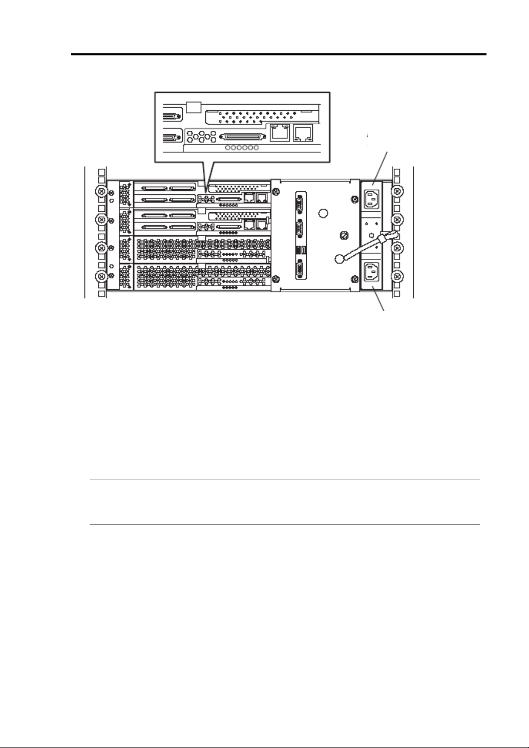
2. Make the PCI module for Group1 primary.
The location of the parts required for operations and check are shown below. (The diagram
shows the rack-mount model. The only difference from the tower model is the orientation.)
BMC status lamp
PCI module status lamp1
PCI module
status lamp2
PCI module
(for Group2)
PCI module
(for Group1)
CPU modules
Rack-mount model
CD-ROM drives
POWER switch
Page 53
Windows Setup 3-13
AC inlet B
(for Group1)
AC inlet A
(for Group2)
Rack-mount model
<When the AC power is off> (The power cord is not plugged into the wall outlet.)
Connect the power cord to NEC Express5800/ft series in the following order:
1 Connect the power cord to the AC inlet B (for Group1)
2 Connect the power cord to the AC inlet A (for Group2)
3 Confirm that the POWER switch of the PCI module for Group1 is illuminated.
4 Make sure that the two BMC status LEDs for PCI modules (for Group1/for Group2) are
turned off.
IMPORTANT:
While the BMC status LED is red and blinking, do not start the ft series setup. Otherwise the
setup may not be done properly.
Preparation is now completed. Start the ft series setup.
<When the AC power is on> (The power cord is plugged to the wall outlet and the main unit’s
power is off)
1 Check the lamp of the PCI module’s POWER switch.
• If the PCI module for Group1’s POWER switch is lit, PCI module for Group1 is
primary. Preparations are complete. Start the ft series setup.
• If the PCI module for Group2’s POWER switch is lit, the PCI module for Group1
is secondary. Continue to step (2). Make PCI module for Group1 the primary
module.
Page 54

3-14 Windows Setup
2 Make sure that the two BMC status LEDs of the PCI modules (for Group1/for Group2) are
turned off.
IMPORTANT:
While the BMC status LED is red and blinking, do not perform steps (3) and on. Otherwise
the BMC firmware may become damaged.
3 Remove the power cord of the AC inlet A (for Group2).
4 Check that the POWER switch of the PCI module for Group1 is turned on.
5 Connect the power cord of the AC inlet A (for Group2).
6 Make sure that two BMC status LED for PCI modules (for Group 1/for Group 2) are turned
off.
IMPORTANT:
If the BMC status LED is red and blinking, do not start the ft series setup. Otherwise the setup may not
be done properly.
Preparation is now completed. Start the ft series setup.
Page 55

Windows Setup 3-15
Starting the ft series setup
Follow the steps below to perform ft series setup:
IMPORTANT: If you skip the settings of “SWITCHING BOOT MONITORING FUNCTION
~CHANGING BIOS SETTINGS~” (page 3-2), BIOS will be restarted forcefully while Windows
setup screen is shown and the setup will be unsuccessful; BIOS may repeat Windows setup in an
invalid manner. In this case, you will need to restart the setup procedures from the beginning.
1. Turn on the peripheral equipment and then the NEC Express5800/ft series.
2. Insert the NEC EXPRESSBUILDER CD-ROM into the CD-ROM drive of the server.
IMPORTANT: For ft series setup, insert the CD-ROM into the PCI module for Group1’s
CD-ROM drive.
3. When having inserted the CD-ROM correctly, reset the system (press
together), or turn the power off and then turn it on to restart the NEC Express5800/ft series.
The system starts through the CD-ROM, and NEC EXPRESSBUILDER is activated.
4. Click [Setup].
5. When the following message appears, click [Confirm].
Note
We recommend you that you should save the information proper to your
system after system setup. If not, you will not be able to recover the
information. You can save the information by the following process.
(1) Select ‘Tools’. (2) Select ‘Off-line Maintenance Utility’.
(3) Select ‘System Information Management.’ (4) Select ‘Save’.
[Confirm]
Ctrl, Alt and Delete
Page 56

3-16 Windows Setup
N
N
6. When the following message appears, read it and press Enter.
This program will delete all existing files on the system drive,
and install Windows Server 2003.
After which required NEC Express server software will be installed.
ote - BIOS "Boot Monitoring" configuration must be set to "Disable"
Please refer to the User's Guide for details.
ote - This program will automatically reboot the system.
Leave the CD-ROM in the CD-ROM drive.
Warning - Be sure to back up all data on the system drive before proceeding.
Press “Enter” to continue or CTRL-C to abort and exit to DOS
The message below appears and the disk is initialized.
While this message is being displayed, the disk is being initialized. Please wait.
Starting the Express5800/ft series clear installation
initializing a disk...
When the disk initialization is complete, the NEC Express5800/ft series automatically restarts.
After the NEC Express5800/ft series is restarted, the following message appears and starts
formatting the hard disk drive:.
CHECK The message “The system will be rebooted.” appears on the screen momentarily. The
server will restart automatically so do not perform any operations.
Installing required software ...
Formatting drive...
FORMAT v7.10 (Revision4.11.1364)
Copyright(c) 1989-2002 Datalight, Inc.
Formatting 3.07G
XX percent complete.
Page 57

Windows Setup 3-17
N
After the hard disk drive is formatted, the message about copying the NEC Express5800/ft series
system software to the system drive from the CD-ROM.
Wait about 5 minutes until copying is completed.
Copyright(c) 1989-2002 Datalight, Inc
Formatting 3.07G
100 percent complete
Writing out file allocation table
Complete.
Calculating free space (this may take several minutes). . .
Complete.
Format complete.
System transferred
3,068.90 MB total disk space
114,688 bytes used by system
3,068.79 MB available on disk
4,096 bytes in each allocation unit.
785,606 allocation units available on disk.
Volume Serial Number is XXXX-XXXX
Copying necessary NEC Express5800/ft series system software to the
system drive... Approximately 5 minutes.
7. After finishing copying the software to the system drive, the following message will appear.
Remove the CD-ROM and press Enter. The NEC Express5800/ft series is restarted automatically.
ecessary NEC Express5800/ft series software has been copied.
Remove the CD-ROM from the CD-ROM drive, and press [ENTER] to finish.
The system will reboot from the Hard Disk Drive.
IMPORTANT: Make sure to remove the CD-ROM from the CD-ROM drive. If the machine
starts up with the CD-ROM inside, the system will be started up from the CD-ROM and NEC
EXPRESSBUILDER will be started.
8. When the NEC Express5800/ft series is restarted, the following message will appear.
Choose one of the following operations:
- If you have “ft Update CD”, enter “Y” and go on to step 9.
- If you do not have “ft Update CD” and perform installation only with “NEC
EXPRESSBUILDER”, enter “N” and go on to step 10.
If you have an additional ft Update CD and wish to use it,
insert the CD-ROM into the CD-ROM drive.
Use an additional ft Update CD?[Y,N]?
9. When “Y” is entered in step 8, the following message will appear.
Page 58

3-18 Windows Setup
[Y,N]
Insert the “ft Update CD” into the CD-ROM drive and press Enter.
If you have an additional ft Update CD and wish to use it,
insert the CD-ROM into the CD-ROM drive.
Use an additional ft Update CD?[Y,N]?
Insert the ft Update CD into the CD-ROM drive and press ENTER.
10. “Important 1” message will appear.
Read the message and follow the instructions.
*** Important 1
- Confirm that there are no optional boards installed into the
PCI module.
If there are optional boards installed into the PCI module,
terminate the installation process and remove the boards,
and then restart the installation process.
Caution: When optional boards are installed into the PCI module,
the installation process will not complete properly.
Terminate installation?[Y,N]?
11. “Important 2” message will appear.
Read the message and follow the instructions.
*** Important 2
- Confirm that only 1 Hard Disk Drive is inserted into the PCI module
(Group1).
If there is more than 1 Hard Disk Drive in the PCI module (Group1),
terminate the ft series setup, and remove all of the Hard Disk Drives,
leaving only the Hard Disk Drive inserted into slot 1 of the PCI module
(Group1).
Caution: If you continue installation will multiple Hard Disk Drives
inserted, the server will not be able to determine the
destination of the installation, and may result in an improper
installation.
Terminate installation?
?
Page 59

12. “Important 3” message will appear.
y
N
Read the message and follow the instructions.
*** Important 3
- Confirm that all PCI and CPU modules are inserted into the machine.
If there are any un-inserted PCI or CPU modules, please insert them
at this time. After the insertion of all of the modules,
press any key to continue installation.
Strike a key when ready . . .
13. “Important 4” message will appear.
Read the message and follow the instructions.
*** Important 4
- Confirm that no LAN cables are connected to the server at this
time.
If there are LAN cables connected to the server, remove them,
and press any key to continue the installation process.
Strike a ke
when ready . . .
14. When “Y” is entered in step 8, the following message will appear.
Wait for about 3 minutes until copying is completed.
Copying necessary NEC Express5800/ft series system software to the
system drive... Approximately 3 minutes.
ecessary NEC Express5800/ft series software has been copied.
Windows Setup 3-19
IMPORTANT: When “N” is entered in step 8, the above message will not appear. Go on to
step 15.
15. When message requesting for Windows Server 2003 CD-ROM appears, follow the instruction on
the screen and insert the Windows Server 2003 Enterprise Edition CD-ROM into the CD-ROM
drive.
Insert the Windows Server 2003 CD-ROM
Strike a key when ready . . .
Page 60

3-20 Windows Setup
N
N
N
N
16. When message for inputting Windows Server 2003 product ID appears, enter the product ID.
Input the WindowsServer2003 ProductID.
ote: Hyphens must be inserted.
Input example: XXXXX-XXXXX-XXXXX-XXXXX-XXXXX
ProductID?
17. The confirmation message for input Windows Server 2003 product ID will appear.
When it is correct, enter “Y”. If it is wrong, enter “N” and press Enter.
ProductID :
XXXXX-XXXXX-XXXXX-XXXXX-XXXXX
Are you sure (Y/N)?
18. The message for inputting the size of the partition to install the OS.
Enter the partition size and press Enter.
IMPORTANT: Refer to “Size of the Partition to be Created” in page 3-8 and be sure to
specify more than the minimum required partition size. If you specify a partition size less than
the minimum size, the installation may fail.
Enter the size of the partition to create.
ote 1:The minimum partition size is 3072 MByte.
1GByte is 1024MByte.
ote 2:If a size larger the HDD capacity is specified,
the entire capacity of the HDD will be used.
ote 3:Input "ALL" to use the entire capacity of the HDD
for the system partition.
Desired Size (Unit: MByte)
19. The confirmation message for input size of the partition to install the OS will appear.
When it is correct, enter “Y”. If it is wrong, enter “N” and press Enter.
The desired system partition size is XXXX.
Are you sure (Y/N)?
20. The following message will be displayed:
Copying Windows Server 2003 to the system drive. . .
Approximately 20 minutes.
Page 61

Windows Setup 3-21
21. When the language type selection message for Microsoft HotFix to install appears, enter a number
of language type to install.
Install which version of the Microsoft HotFix?
1.English
2.Simplified Chinese
3.Traditional Chinese
4.Other
Enter a number [1,2,3,4]?
22. When the completion of copying Microsoft HotfFix, the following message will appear.
Follow the instruction on the screen, insert appropriate CD-ROM and press any key.
Microsoft HotFix will be copied to the Hard Disk.
- If you are using only the NEC EXPRESSBUILDER for ft series setup,
insert the NEC EXPRESSBUILDER to the CD-ROM drive,
and press any key to continue the installation process.
.
- If you are using the ft Update CD for ft series setup,
insert the ft Update CD to the CD-ROM drive,
and press any key to continue the installation process.
Strike a key when ready . . .
23. The following message will appear. Wait until copying process completes.
Copying necessary NEC Express5800/ft series system software to the
system drive... This may take a few moments.
24. When the following message appears, remove the CD from the CD-ROM drive and press any key.
Remove CD-ROM from the CD-ROM drive.
Strike a key when ready . . .
Page 62

3-22 Windows Setup
25. When copying is complete, the installation of Windows Server 2003 will be started automatically.
Windows Setup
Please wait while Setup copies files to your hard disk.
Setup is copying files…
50%
CopyingXXXXXXXX
IMPORTANT:
During the automatic installation process (steps 26 to 36) a window may be displayed
showing the progress as well as application installation wizards. Do not perform any
operations until the “Windows Setup Wizard” in step 37 is displayed.
During the automatic installation process (steps 26 to 36) NEC Express/ft series restarts
several times for setup until the “Windows Setup Wizard” starts.
26. The system will be automatically rebooted. No user intervension is required.
Windows Setup
Please wait while Setup copies files to your hard disk.
Setup is copying files…
50%
CopyingXXXXXXXX
IMPORTANT:
When rebooting, the message “Press any key to boot from CD.” will appear, but do not
perform any operations.
The selection of “Previous Operating System C:” may be displayed on the OS selection
screen. Do not select it. Doing so will display DOS prompt and the process will be stopped.
In such case, press
installation will be continued.
27. After the the system is automatically rebooted, the file system will be changed from FAT32 to
NTFS and the file system will be converted automatically. There is no user intervension.
28. Aftt the system is restarted, the setup screen will be displayed and the setup will proceed
Ctrl + Alt + Delete to restart the system. After the system is rebooted, the
Page 63

Windows Setup 3-23
automatically. There is no user intervension.
The following settings are made automatically:
[Collecting information]→[Dynamic Update]→[Preparing installation]→
[Installing Windows]→[Finalizing installation]
IMPORTANT: When restarting, the message “Press any key to boot from CD.” will appear,
but do not perform any operations.
29. The system will be automatically rebooted. No user intervension is required.
IMPORTANT:
When rebooting, the message “Press any key to boot from CD.” will appear, but do not
perform any operations.
The selection of “Previous Operating System C:” may be displayed on the OS selection
screen. Do not select it. Selecting “Previous Operating System C:” will display black screen
and the process will be stopped. In such case, press CTRL + ALT + DELETE to restart the
system. After the system is rebooted, the installation will be continued.
30. After the system is rebooted, the following message will appear and the instllation will be
continued. The system configuration is done automatically. Do not perform any operations.
Express5800/ft series clear installation
** Please do not perform any operations. **
** The system will restart automatically. **
Configuring System.
The system will automatically restart in approximately 2 minutes.
*** Setting [ft server environment] ***
*** Checking [disk space] ***
The system will automatically restart in approximately 10 minutes.
IMPORTANT: Never terminate the above program while it is running. If it is terminated by
closing the window, etc., the installation will be stopped. In such case, operations on Windows
will be possible, but each module or PCI board will not be duplicated properly. If this happens,
you need to start over ft series setup.
Page 64

3-24 Windows Setup
31. After restarting, the following screen will appear and the installation will be continued. Do not
perform any operations. The Express5800/ft series software is installed automatically.
Express5800/ft series clear installation
** Please do not perform any operations. **
** The system will restart automatically. **
*** Setting [ft series environment (Preparation)] ***
*** Setting [ft series environment (NECHWID)] ***
*** Setting [Timeout for non-communication time] ***
*** Installing [Stratus Big Board Driver] ***
*** Installing [IPMI] ***
*** Installing [PROSET II] ***
*** Installing [SRAPS] ***
*** Installing [mof file] ***
*** Installing [Stratus Debug Print Driver] ***
*** Installing [NEC ESMPRO Agent] ***
IMPORTANT: Never terminate the above program while it is running. If it is terminated by
closing the window, etc., the installation will be stopped. In such case, operations on Windows
will be possible, but modules or PCI boards will not be duplicated properly. If this happens,
you need to start over the ft series setup.
32. The following screen will appear and installation of NEC ESMPRO Agent will be started.
The NEC ESMPRO Agent install wizard starts up and installation is done automatically. Do not
perform any operations.
Page 65

Windows Setup 3-25
33. The following screen will appear and the setup of Express Report Service will start. Do not
perform any operations. The Express Report Service Setup wizard starts and installation is done
automatically.
34. The following screen will appear and installation of Windows HotFix will begin.
The Windows HotFix install wizard starts up and installation is done automatically.
Do not perform any operations.
Express5800/ft series clear installation
** Please do not perform any operations. **
** The system will restart automatically. **
*** Setting [ft series environment (Preparation)] ***
*** Setting [ft series environment (NECHWID)] ***
*** Setting [Timeout for non-communication time] ***
*** Installing [Stratus Big Board Driver] ***
*** Installing [IPMI] ***
*** Installing [PROSET II] ***
*** Installing [SRAPS] ***
*** Installing [mof file] ***
*** Installing [Stratus Debug Print Driver] ***
*** Installing [NEC ESMPRO Agent] ***
*** Installing [Express Report Service] ***
*** Installing [BMCTOOL] ***
*** Setting [Configuration of ft dump] ***
*** Setting [Hardware Accelerator] ***
*** Installing [Hotfix] ***
Page 66

3-26 Windows Setup
35. After installation of Windows HotFix is complete, installation is continued.
Do not perform any operations. When the NEC Express5800/ft series software is installed, the
NEC Express5800/ft series will be restarted automatically.
Express5800/ft series clear installation
** Please do not perform any operations. **
** The system will restart automatically. **
*** Setting [ft series environment (Preparation)] ***
*** Setting [ft series environment (NECHWID)] ***
*** Setting [Timeout for non-communication time] ***
*** Installing [Stratus Big Board Driver] ***
*** Installing [IPMI] ***
*** Installing [PROSET II] ***
*** Installing [SRAPS] ***
*** Installing [mof file] ***
*** Installing [Stratus Debug Print Driver] ***
*** Installing [NEC ESMPRO Agent] ***
*** Installing [Express Report Service] ***
*** Installing [BMCTOOL] ***
*** Setting [Configuration of ft dump] ***
*** Setting [Hardware Accelerator] ***
*** Installing [Hotfix] ***
*** Installing [Strage Manager] ***
*** Setting [NECDUMP] ***
*** Setting [Memory copy (Brown copy)] ***
*** Setting [WindowsOS] ***
*** Setting [Disk] ***
*** Setting [ft version information] ***
The system will automatically restart in approximately 10 seconds.
36. After the system is restarted, the following screen will appear and the installation is continued. Do
not perform any operations. NEC Express5800/ft series is configured and the system is restarted
automatically.
Express5800/ft series clear installation
** Please do not perform any operations. **
** The system will restart automatically. **
Scanning for PCI Module (Group 2)
PCI Module (Group 2) recognized.
*** Setting [Configuration of PCI auto bringup] ***
*** Setting [Server wizard on] ***
The system will automatically restart in approximately 10 seconds.
. . . . . . . . . . . . . . .
Page 67

Windows Setup 3-27
IMPORTANT: Never terminate the above program while it is running. If it is terminated by
closing the window, etc., the installation will be stopped. In such case, operations on Windows
will be possible, but modules or PCI boards will not be duplicated properly. If this happens, you
need to start over the ft series setup.
37. After restarting, the [Welcome to the Windows Setup Wizard] screen will appear.
Click
[Next>] and follow the instruction of the wizard. After compling operations in the wizard,
the NEC Express5800/ft series will be restarted automatically.
IMPORTANT: Read [License Agreement] thoroughly.
If you agree, click [I accept this agreement.] and click [Next>].
If you do not agree, click [I don’t accept this agreement.] and click [Next>].
If you do not agree, the setup will be terminated and Windows will not be installed.
38. After the machine is restarted, it is automatically logged on using a user name of Administrator.
When the dialog below appears, read the information and click “OK”.
IMPORTANT: At the bottom right of the screen, “Display Settings” may be displayed. In
such case, change the “Colors” setting to “Medium (16 bit)” or higher.
[Display Properties] – [Settings] tab – [Color quality]
39. Update software programs
If you have performed installation using "NEC Express5800/ft series ft Update CD," apply all
update modules by referring to "ftcont_sw_vnn.doc " in the CD-ROM. However, it is unnecessary
to apply individual update modules here because the latest update module is automatically applied
from the NEC Express5800/ft series ft Update CD-ROM.
- ft control software (Ver:n.n) update module
Although NEC ESMPRO Agent is automatically installed at ft series setup, the latest module is not
applied. You need to apply an update module separately from NEC Express5800/ft series ft Update
CD.
Now the installation of Windows Server 2003 is complete.
Page 68

3-28 Windows Setup
SETTING DUAL LAN CONFIGURATION
The NEC Express5800/ft series builds a dual LAN configuration by using "Stratus emb-82559 10/100
Enet Adapter" (100Base) and "Stratus emb-82544GC Copper Gigabit Adapter" (1000Base) mounted
as standard on the PCI module.
TIPS:
This is a configuration which is required only when the keyboard is connected via SSU at
reinstallation. For other cases, this setting is not necessary, so proceed to the next setting.
To set dual LAN configuration, log on as "Administrator" or a member of the group
"Administrators".
1. Display the [Intel(R)PROSet II] dialog box.
2. Start one of the start menu modes below:
Standard start menu mode
Click [Intel(R)PROSet II] in [Control Panel] from the [Start] menu.
Classic start menu mode
(1) Select [Settings] - [Control Panel] from the [Start] menu.
(2) Double-click the [Intel(R)PROSet II] icon.
3. Select [Network Components] from
Network Component Tree. The
pop-up menu appears. Select [Create
New Team...] → [Fault Tolerance].
IMPORTANT: Do not select the
command other than [Fault Tolerance]
on the standard PCI module.
[Team #1: Adaptive Fault Tolerance
Mode] is added to Network
Component Tree.
Page 69

Windows Setup 3-29
4. Select [Stratus emb-82559 10/100
Enet Adapter] from Network
Component Tree. The pop-up
menu appears. Select [Add to
Team] → [Team #1: Adaptive
Fault Tolerance Mode], and add
the adapters.
You will see the warning message
when you add the team. You can
ignore this warning message by
clicking [OK]. This warning
message is to inform you that only
one adapter is added to the team.
5. Select [Stratus emb-82559 10/100 Enet Adapter #2] from Network Component Tree in the
same manner as for step 4. The pop-up menu appears. Select [Add to Team] → [Team #1:
Adaptive Fault Tolerance Mode], and add the adapters.
IMPORTANT: Do not set [Preferred Primary] or [Preferred Secondary] to each adapter.
6. Make settings of dual configuration for "Stratus emb-82544GC Copper Gigabit Adapter"
(1000Base) as well.
Perform Steps 3 to 5 in the same manner, replacing [Stratus emb-82559 10/100 Enet Adapter]
with [Stratus emb-82544GC Copper Gigabit Adapter].
In Step 3, you can also select [Load Balancing]. In this case, [Team #X: Adaptive Load
Balancing Mode] will be added.
7. Click [OK].
The [Intel(R)PROSet II] dialog
box closes after a while, and the
settings become effective.
IMPORTANT:
[Digital signature not found]
dialog box may appear
(several times). If it appears,
click [Yes].
After the settings of dual
configuration, “Intel(R)
Advanced Network Services
Virtual Adapter” will appear
on [Network and dialup connection] or [Device Manager] dialog box. Do not
“disable” the status of this adapter. If you enable it again, the system may become
unstable and you may need to restart it.
Page 70

3-30 Windows Setup
SETTING DUAL DISK CONFIGURATION
NEC Express 5800/ft series secures data by mirroring disks. Be sure to make dual disk settings.
TIPS: To set dual disk configuration, log on as "Administrator" or a member of the group
"Administrators".
IMPORTANT:
Make sure to mirror the volumes not only when installing an operating system but also when
creating partitions.
After upgrading the volume that contains system partition to dynamic disk, set the disk for
mirroring to the slot. Do not set the disk to the slot before upgrading.
Set the mirroring for the disk with the same target ID. See " HARD DISK CONFIGURATIONS
THAT CAN BE BUILT ON THE NEC Express5800/ft series" in the separate volume of User’s
Guide for details.
1. Select [Start] → [Setting] → [Control Panel], and then [Control Panel] screen appears
2. Click [Disk Management] under the Storage branch of the tree view menu.
3. Display the hard disk list on in the right frame, right-click the disk where the system is
installed and click [Convert to Dynamic Disk…].
Page 71

Windows Setup 3-31
4. Confirm that the disk to be converted is the disk where the system is installed and click
[Convert].
If the selected disk contains a system partition, you will have to restart the computer to
complete the upgrade of the disk. The message also states that file systems on any of the disks
to be upgraded will be forcedly dismounted. This means if any file systems are in use at the
time of upgrade, they will be dismounted, so that the upgrade can continue.
5. After the system has restarted, display [Disk Management] again and set the disks for creating
mirror volume.
IMPORTANT:
When the disk status is “Not Initialized”, right-click that disk and initialize it.
If “Foreign” is displayed, perform “Convert to Basic Disk” and then perform “Convert to
Dynamic Disk…”.
Disks to be mirrored must be inserted to the corresponding slots. For details, see the diagram
below:
Slot3
Group1
Group2
Corresponding slots for mirroring process
Page 72

3-32 Windows Setup
6. If the inserted disk is not
a dynamic disk,
right-click the disk and
perform “Convert to
Dynamic Disk…”.
7. Right-click the dynamic
disk volume for creating
mirror and click [Add
Mirror…].
IMPORTANT:
When you click [Add Mirror…], the [Logical Disk Manager] dialog box will appear,
but this is not an error. Click [OK].
If you restart the system while creating mirror, mirroring will not be completed. Do
not reboot the system until the mirroring process is completed.
TIPS: Creating mirror takes about 37 minutes for 18GB hard disks.
Continue the operation by following the instructions on the screen.
Page 73

Windows Setup 3-33
SWITCHING BOOT MONITORING FUNCTION
Enable the “Boot Monitoring” setting which has been disabled in “SWITCHING BOOT
MONITORING FUNCTION ~CHANGING BIOS SETTINGS~” (page 3-2). See “SWITCHING
BOOT MONITORING FUNCTION ~CHANGING BIOS SETTINGS~” (page 3-2) and change the
setting to “Enabled”.
Page 74

3-34 Windows Setup
Page 75

Chapter 4
Procedures after Completion of Installation
This chapter describes what you do after installation including setup for failure management, how you
install management utilities, how you back up system information, and setup of PCs on the network.
You may need to confirm these procedures wh ile the system is running.
Page 76

4-2 Procedures after Completion of Installation
SETUP FOR FAILURE MANAGEMENT
Make the following settings beforehand to ensure quick recovery from failure.
Setting Memory Dump (Debug Information)
This section explains the setting for collecting memory dump (debug information) in the server.
IMPORTANT: Notes on memory dump
The maintenance personnel designated by your sales agent are responsible for collecting
memory dump. Customers should make settings of memory dump only.
Sometimes a message indicating a shortage of virtual memory appears at the system startup,
when a failure has occurred after making settings described here and you have restarted the
system to save the memory du mp. Continue the sta rtup. If you restart ing the system, you m ay not
be able to collect the memory dump accurately.
Take the following steps to set memory dump:
1. From the [Start] menu , select [Control Panel] and then click [System].
The [System Properties] dialog box
appears.
2. Click the [Advanced] tab.
3. Click [Settings] in the [Setup and
Recovery] box.
Page 77

Procedures after Completion of Installation 4-3
4.
Enter the location, where debug
information is to be written, in the text box.
When writing debug informati on under th
e
file name "MEMORY.DMP" in the D
drive:
D:\MEMORY.DMP
This server has the following location as a
default value for installation. It is
recommendable to store file in this default
location.
%SystemDrive%\NECDump\MEMORY.
DMP
IMPORTANT:
[Full Memory Dump] should be specified for writing debug information. However, if
the mounted memory size is over 2GB, specify [Kernel Memory Dump]; you canno
specify [Full Memory Dump
Specify a drive which has a free space of the size of memory in the NEC
Express5800/ft series + 12MB or more.
If the memory will be expanded to larger than 2 GB, change Write Debugging
Information to [Kernel Memory Dump] before expanding the memory. Size of the
debugging information (memory dump) to be collected will change due to memory
increase. Check how much free space the disk to which debugging information is
has.
written
]
t
Page 78

4-4 Procedures after Completion of Installation
5.
Click [Settings] in the [Performance] box.
The [Performance Options] window appears.
6. Click the [Advanced] tab on the [Performance
Options] window.
7. Click [Change] in the [Virtual memory] box.
Page 79

Procedures after Completion of Installation 4-5
8.
Change the value set for [Initial Size] in the
[Paging file size for selected drive] box to the
[Recommended] value or more, and t hen click
[Set].
IMPORTANT:
Be sure to create the file in the above size in the OS partition. If a value smaller than the
[Recommended] value is set for [Initial Size] of the paging file, accurate debu
information (memory dump) may not be collectedg .
For the [Recommended] value, see "Size of the Partition to be Created" in Chapter 3
To be prepared for failure, it is recommended to press the dump button to see if th
memory dump can be collected in normally beforehan
If the memory has been expanded re-set the paging file according to the memory siz
d.
.
e
e
9. Click [OK].
A message is displayed asking you to restart the system depending on the changed settings.
Restart the system according to the messages.
Page 80

4-6 Procedures after Completion of Installation
Setting Dr. Watson
Dr. Watson of Windows 2003 is a debugger for application errors. When detecting an application error,
Dr. Watson diagnoses the NEC Express5800/ft series, and records the diagnostic information (log).
Take the following steps to collect diagnostic information:
1. Click [Start] → [Run...].
2. Enter "drwtsn32.exe" in the [Open] box, and
click [OK].
The [Dr. Watson for Windows] dialog box
appears.
3. Specify where you want to save diagnostic
information in the [Log File Path] box.
Diagnostic information is saved under the
file name "DRWTSN32.LOG."
TIPS: Do not specify a network path. Be
sure to specify a path on the local computer.
4. Specify the crash dump file save destination
in the [Crash Dump] box.
TIPS: A "crash dump file" is a binary file
that can be read by W in d ow s Deb u gge r.
5. Select the following check boxes in the
[Options] box.
[Dump Symbol Table]
[Dump All Thread Contexts]
[Append To Existing Log File]
[Create Crash Dump File]
For the above functions, see the online
help.
6. Click [OK].
Page 81

Procedures after Completion of Installation 4-7
Installing a Network Monitor
A network monitor is useful for examining the causes of network failures and taking the
countermeasures. T o use the network m onitor , you need to restart the system after the installation. It is
recommended to install the network monitor before a failure occurs.
1. From the [Start] menu , select [Control Panel].
The [Control Panel] dialog box appears.
Click the [Add/Remove Programs] icon.
The [Add/Remove Programs] dialog box appears.
2. Click the [Add/Remove Windows Components].
The [Windows Components Wizard] dialog box appears.
3. Select the [Management and Monitoring Tools] check box of components
If a check box is shaded, the component is partly installed. Clear the shaded check box and
check it again.
4. Click [Next].
5. If a message is displayed asking you to insert "Windows Server 2003, Enterprise Edition"
disk, follow the instructions on the screen and specify the required path.
Close the menu that appears by inserting the CD-ROM. To close the m enu, click the [X] mark
on the menu.
6. Click [Finish] in the [Windows Components Wizard] dialog box.
7. Click the [X] mark on the [Add/Remove Programs] dialog box.
You can also activ ate the network monitor by clicking [Start] → [Programs] → [Administrative
Tools] → [Network Monitor]. For details on the operation, see the online help.
Page 82

4-8 Procedures after Completion of Installation
INSTALLING MANAGEMENT UTILITIES
The provided "NEC EXPRESSBUILDER" CD-ROM contains "NEC ESMPRO Agent" for
monitoring NEC Express5800/ft series and "NEC ESMPRO Manager" for managing the NEC
Express5800/ft series. Install and setup these utilities in the NEC Express5800/ft series or the
computer (management PC) that manages the NEC Express5800/ft series.
NEC ESMPRO Agent
NEC ESMPRO Agent is automatically installed by executing the "ft series setup program.” (It has
been installed on the hard disk of a pre-installed model at shipment.)
Click [Start] → [Programs], and make sure that the installed utility folder exists. If it has not been
installed while setting up the ft series, install it separately.
IMPORTANT: Make sure that NEC ESMPRO Agent is installed because it is indispensable for
continuous operation of NEC Express5800/ ft series.
To set details about NEC ESMPRO Agent, double-click the [NEC ESMPRO Agent] icon in the
[Control Panel] dialog box. The properties dialog box appears for changing the settings.
Page 83

Procedures after Completion of Installation 4-9
For details on the set items, see the online help displayed by clicking on [Help].
Page 84

4-10 Procedures after Completion of Installation
Operation Environment
NEC ESMPRO Agent can be operated in the hardware and software environments shown below.
Hardware
• Installation system NEC Express5800/ft series
• Memory Memory capacity required to operate OS +
25.0 MB or larger
• Empty capacity of hard
disk
Software Windows Server 2003, Windows 2000
50.0 MB or larger
Preparation before Setup
Be sure to read the following description before system installation or setup.
T o operate NEC ESMPRO Agent, you need to m ake settings of TCP/IP and the SNM P of compone nts
associated with TCP/IP.
TCP/IP Setting
See the Help started from the Start menu for how to set TCP/IP.
SNMP Service Setting
To install the SNMP Service:
1.
Open [Add/Remove Programs] in [Control Panel].
2. Click [Add/Remove Windows Components].
3. Select [Management and Monitoring Tools] in the Windows component wizard and click the
[Details...] button.
4. Check the check box of [Simple Network Management Protocol].
5. Click the [Next] button.
The file copy operation is started.
6. After the file copy is finished, click the [Finish] button.
To change the settings of the SNMP Service:
Double-click [Administrative Tool] in [Control Panel].
1.
2. Start [Services] in [Administrative Tool].
Page 85

Procedures after Completion of Installation 4-11
3.
Select [SNMP Service] from the service list and then [Properties] in the [Action] menu.
The "SNMP Properties" dialog box appears.
4. Enter "public" in the [Community name] box in the [Traps] property sheet and click the [Add
to list] button.
IMPORTANT:
To change the community name of traps to be received from the default "public" in the
NEC ESMPRO Manager site, enter the same name as the community name newly set
in the NEC ESMPRO Manager site.
To receive trap from NEC ESMPRO Agent at the NEC ESMPRO Manager machine,
both community names should be the sam
e.
5. Click the [Add...] button in [Trap destinations]. After entering the IP address of the NEC
ESMPRO Manager machine of the send destination in the [Host name, IP or IPX ad dress] box,
click the [Add] button.
IMPORTANT: If the IP address (or host name) of the remote NEC ESMPRO Manager
specified as the trap send destination in the setup of the manager report (TCP/IP), the
message warning the duplication appears. The specification of the same NEC ESMPRO
Manager causes to be reported doubly
.
6. Open [Security] property sheet an d make settin gs as follows;
• Add the community name entered in Step 4 to [Accepted community names].
• Set its authority to [READ CREATE] or [READ WRITE].
• Select [Accept SNMP packets from any host.]
IMPORTANT:
If you entered any community name other than “public” in Step 4, add that name to
“Accepted community names” .
Unless you set the acceptable community’s authority to “READ CREATE” or “READ
WRITE,” you cannot perform monitoring from NEC ESMPRO Manage
r.
< Setup of receiving SNMP packets from specific hosts only >
Select [Accept SNMP packets from these hosts], specify IP addresses of the hosts, IP
addresses of the servers to install Agent, and the loop-back address (127.0.0.1).
< Setup of receiving SNMP packets from specific communities only >
Change the name of the community receiving SNMP packets from the default “public” to
any name.
IMPORTANT:
If the community name is changed, the community of NEC ESMPRO Agent is
changed and registered by starting from [Control Panel]. To change the community to
another and register it, use the [SNMP Community] list box in the
To allow NEC ESMPRO Agent to receive SNMP packets sent from NEC ESMPRO
Manager, set the send community name in NEC ESMPRO Manager to be the same as
that accepted by the SNMP Service in NEC ESMPRO Agent.
[General] tab.
Page 86

4-12 Procedures after Completion of Installation
7.
Terminate the network setup.
IMPORTANT:
If the SNMP Service is added after adaptation of the service pack in installation of OS,
adapt the service pack again. If not, the SNMP Service may not operate correctly. Thi
then disables NEC ESMPRO Agent to be operate
The SNMP Service is required for operating NEC ESMPRO Agent. If the SNMP
d.
s
Service is deleted after the installation of NEC ESMPRO Agent, install the SNMP
Service and then reinstall NEC ESMPR
Some software products provided by other vendors us e the SNMP Service. If the
SNMP Service and NEC ESMPRO Agent are installed in the system in which such
O Agent.
software as above is installed, it may be impossible to start NEC ESMPRO Agent
services. If so, delete the SNMP Service once and install the service again. After which
reinstall NEC ESMPRO Agent and the other vendor's so
ftware.
,
System Update
To install NEC ESMPRO Agent, necipmi.sys needs to be installed in advance. For the installation of
necipmi.sys, use the NEC EXPRESSBUILDER CD-ROM shipped with the system to update the
system. (see page 5-11 ).
If necipmi.sys is not installed yet, the message shown below appears and the setup of NEC ESMPRO
Agent is suspended.
"NEC ESMPRO Agent requires the following file.
Please update NEC Express5800 system before installing NEC ESMPRO Agent.
necipmi.sys"
Page 87

Procedures after Completion of Installation 4-13
Installation
NEC ESMPRO Agent is automatically installed together with the installation or re-installation of the
NEC Express5800/ft series. NEC ESMPRO Agent may be installed manually on the master control
menu of NEC EXPRESSBUILDER as follows:
1. Login to the system with user name “Administrator.”
2. Insert CD-ROM "NEC EXPRESSBUILDER" into the CD-ROM drive.
TIPS: The CD-ROM drive may be either the drive connected to the system or any drive
located on the network and connected by the LAN Manager. (These are collectively called
CD-ROM drive hereafter) .
IMPORTANT: To use a CD -ROM dri ve on the net wor k, a ssi gn the netw ork dri ver t o th e
drive and then execute MC\1ST.EXE of the drive. Do not start the CD-ROM drive from the
network computer in Explorer.
The autorun function automatically displays the master control menu of NEC
EXPRESSBUILDER.
3. Click [NEC ESMPRO] in [Setup].
The NEC ESMPRO setup is started to display
the main menu.
4. Click [Agent] in the main menu of the NEC
ESMPRO setup.
TIPS: The available menus vary depending on
OS types. (The menus that cannot be installed
are displayed gray .)
IMPORTANT:
Double-clicking to select a menu may display two same dialog boxes. Click the [End]
button to close one of the dialog boxes.
If you click the [Cancel] button during setup, the message asking whether to stop or not to
stop the installation will appear. You can stop the installatio n by clicking on the [Stop
button (the main menu rem ains display ed). However, the file having been setup halfway
will not be delete
d.
]
Page 88

4-14 Procedures after Completion of Installation
5.
Click the [Next] button.
TIPS: If NEC ESMPRO Agent is already
installed, the dialog box "NEC ESMPRO
Agent already installed" appears. Clicking
on the [Update] button and then the [Next]
button will erase the old agent and install
the NEC ESMPRO Agent a
new.
6. The setup program determines the machine type automatically.
TIPS: If the setup program fails in the determination of the machine type, the dialog box
for selecting the machine type will appear. Select the machine to install from the list.
7. Enter the path in which NEC ESMPRO Agent is installed and click the [Next] button.
The NEC ESMPRO Agent module is installed below the \ESM directory of the root partition
in default. If no problem is found, click the [Next] button without any modification.
To change the installation directory, click the [Reference] button, specify the desired
installation directory with the full path including the drive name, and click the [Next] button.
8. When the installation end window appears, click th e [OK] button.
The installed is complete. The functions of installed NEC ESMPRO Agent will be enabled
after the system is restarted.
IMPORTANT:
After the installation of NEC ESMPRO Agent, SNMP Service is stopped. The SNMP
Services will be started when the OS is restarted.
Even if the installation of NEC ESMPRO is completed, the main menu for the NEC
ESMPRO setup remains displayed. Note that the main menu may be hidden by
another dialog box. To terminate the NEC ESMPRO setup, click [End] in the main
menu.
Page 89

Procedures after Completion of Installation 4-15
Setup of NEC ESMPRO Agent
The settings of installed NEC ESMPRO Agent remain unchanged from those at shipment. Click the
[Start] button, [Setting], and [Control Panel] sequentially to open the [Control Panel].
If you double-click the [NEC ESMPRO Agent] icon in [Control Panel], the property dialog box will
appear. Modify the setting of each sheet in the dialog box to be fit to the used environment. The notes
on setup and the necessary information are explaine d in “Supplement” in Chapter 5 of User’s Guide in
the separate volume. See the supplement for setup or suspicion of malfunction.
Page 90

4-16 Procedures after Completion of Installation
Uninstall
The configuration of NEC ESMPRO Agent and BMC and the uninstallation of BMC FW Update
Service are described below.
Uninstallation of NEC ESMPRO Agent
The procedure of uninstalling NEC ESMPRO Agent is described below.
IMPORTANT: Uninstallation of NEC ESMPRO Agent
Start the uninstallation of NEC ESMPRO Agent after the system is started completely.
If NEC ESMPRO Agent is uninstalled just after the system startup, the setup program may
freeze displaying the [Service Being Deleted…] dialog box. Shutdown the system by using
"Task Manager" or other operation. Then uninstall NEC ESMPRO Agent after the system is
started completely.
With use of NEC EXPRESSBUILDER:
1. Make the main menu of the NEC ESMPRO setup appear by referring to the section "Install"
in this document.
2. Click [NEC ESMPRO Agent].
The [Welcome to Setup of NEC ESMPRO Agent] dialog box appears.
3. Click the [Next] button.
Message "NEC ESMPRO Agent is already installed" appears.
4. Select [Delete] and then click the [Next] button.
Now NEC ESMPRO Agent is uninstalled.
Without use of NEC EXPRESSBUILDER:
1. Start [Add/Remove Programs] on [Control Panel].
2. Select [NEC ESMPRO Agent] and click [Add/Remove].
Now NEC ESMPRO Agent is uninstalled.
Page 91

Procedures after Completion of Installation 4-17
Uninstallation of BMC Configuration and BMC FW Update Service
If NEC ESMPRO Agent is installed, the uninstaller of the BMC configuration and that of NEC BMC
FW Update Service are registered.
The use of these uninstallers allows the BMC configuration and NEC BMC FW Update Service to be
deleted as follows:
1. Start [Add/Remove Programs] on
[Control Panel].
2. Select [NEC BMC Configuration] or
[NEC BMC FW Update Service] and
click [Change/Remove].
Page 92

4-18 Procedures after Completion of Installation
NEC ESMPRO Manager
Linked with NEC ESMPRO Agent installed in the server, NEC ESMPRO Manager monitors the
server status and receives alerts from the server.
NEC ESMPRO Agent
Error
Notify
Monitor
When a failing module in the server is to be replaced, NEC ESMPRO Manager enables logical
module disconnection from the server and logical installation after module replacement.
For the installation of NEC ESMPRO Manager and notes on the operation, see Chapter 5 in User’s
Guide.
NEC ESMPRO Manager
NEC MWA
NEC MWA is an application that enables remote management of the server (this product) through a
management PC over the network. (A management PC is a computer running NEC ESMPRO
Manager.)
To establish communication between the server and the manage ment PC, install “NEC MWA” in the
management PC. For NEC MWA, see Chapter 5 in User’s Guide in the separate volume.
Page 93

Procedures after Completion of Installation 4-19
System Requirement
The hardware and software environm ent in which NEC MWA runs is:
• Management PC (to install NEC MWA)
NEC MWA runs on a computer where Windows is operated. For more information, see “MWA
First Step Guide.”
• The servers that can be maintained remotely by NEC MWA
Servers which the User’s Guide provided with NEC Express5800 /ft series includes descriptions
of NEC MW A. The servers are equipped with RomPilot or BMC. This product is has with BMC
(IPMI1.0) and RomPilot.
Installation of NEC MWA Manager
T o mange this pro duct using NEC MWA, install NEC M WA Manager on the management PC . Use the
“NEC EXPRESSBUILDER” CD-ROM to install NEC MWA Manager.
1. Start up Windows.
TIPS: For OS compatibility, see “MWA First Step Guide”.
CR-ROM drive: \mwa\doc\jp\mwa_fsg.pdf
2. Insert the “EXPRESSBUILDER” CD-ROM into the CD-ROM drive.
Master Control Menu of NEC EXPRESSBUILDER will be automatically displayed.
3. Click [Setup], then [MWA].
TIPS: You can also display the popup menu by
right-clicking the screen shown right.
4. Click [NEC MWA Manager].
NEC MWA installer starts up. Follow the instructions to install.
Page 94

4-20 Procedures after Completion of Installation
BACKUP OF SYSTEM INFORMATION
After setting up the system, back up the system information using the Off-line Maintenance Utility.
Without backup for system information, the information and settings that are specific to your server
cannot be restored if the server is repaired. Take the following steps to make a backup copy of the
system information:
1. Get a 3.5-inch floppy disk.
2. Insert the "NEC EXPRESSBUILDER" CD-ROM into the CD-ROM drive of the server, and
restart the system.
NEC EXPRESSBUILDER is activated and the [NEC EXPRESSBUILDER Top Menu] is
displayed.
3. Select [Tool] → [Off-line Maintenance Utility].
4. Select [Save System NVRAM/ROM Data] from [System Information Management].
Follow the instructions you see on the screen.
Page 95

Procedures after Completion of Installation 4-21
SETTING UP PCS ON A NETWORK
If you have computers running on Windows Server 2003, Windows XP/2000/NT4.0, Windows 95/98
that communicate with NEC Express5800/ft series using the TCP/IP protocol, make the following
settings on all computers.
1. Copy the following in the EXPRESSBUILDER CD-ROM or ft control software, UPDATE
CD-ROM to any directory.
\STRATUS\LANG\EN\PROG\FTREG.EXE
TIPS: ft Update CD is for updating ft control software. It may not be attached to the
product. If software included in the EXPRESSBUILDER CD-ROM is latest at the time
of shipment, the ft Update CD is not attached.
2. Start up the command prompt and enter the directory in which the file mentioned above is
copied, and then enter the following command.
FTREG.EXE
This setting is to avoid a timeout caused by non-communication state between the NEC
Express5800/ft series and computers connected by the LAN protocol that may occur
immediately after the NEC Express5800/ft series startup or a CPU module reinstallation (dual
processing).
Non-communication time immediately after the NEC Express5800/ft series startup or module
reinstallation in the system where Windows Server 2003 runs is proportional to the size of
memory mounted and how much applications running use memory.
Page 96

4-22 Procedures after Completion of Installation
Because minimum non-communication time is momentary regardless of size of the memory
installed, it will not be considered as non-communication. Maximum non-communication time
by the memory size is as follows:
Memory size Non-communication time
256MB About 3.1 seconds
512MB About 6.2 seconds
1GB About 12.3 seconds
2GB About 24.7 seconds
3GB About 36.3 seconds
6 GB About 47.0 seconds
This setup program sets the following Windows registry:
Windows XP/Windows NT/Windows 2000/Windows Server 2003:
Registry key:
HKEY_LOCAL_MACHINE\SYSTEM\CurrentControlSet\Services\Tcpip\Parameters
Values: TcpMaxConnectRetransmissions
Type: REG_DWORD
Set value: 5
Values: TcpMaxDataRetransmissions
Type: REG_DWORD
Set value: 8
Values: TcpMaxConnectREsponseRetransmissions
Type: REG_DWORD
Set value: 5
Windows 95/98/Me:
Registry key:
HKEY_LOCAL_MACHINE\SYSTEM\CurrentControlSet\Services\VxD\MSTCP
Values: MaxConnectRetries
Ty pe : St ri ng
Set value: 5
Values: MaxDataRetries
Type: String
Set value: 8
Page 97
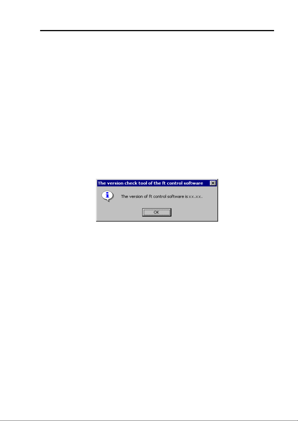
Procedures after Completion of Installation 4-23
CONFIRMATION OF THE ft CONTROL SOFTWARE VERSION
The following describes how to check the version of ft control software, which consists of various
types of software for fault tolerance. Perform the procedure when you ne ed to check the ft control
software version of the current system before adding units or attachment to NEC Express5800/ft
series.
A tool for checking the version is provided. Confirm the version following the steps below:
1. Log in the system as an authorized Administrator.
2. Insert the provided "NEC EXPRESSBUILDER" CD-ROM in the CD-ROM drive.
Use the NEC Express5800/ft series ft Update CD, if it is available.
3. Run the tool installed in the CD to check the version of ft control software.
Tool name: ftVerChk.exe
Location: <CD-ROM drive>: FTSVTOOL\VERSION
The ft control software version of the current system is displayed.
This completes confirmation of the version.
Page 98

4-24 Procedures after Completion of Installation
About Service Pack
Customers should not apply service pack on NEC Express5800/ft series by themselves.
IMPORTANT: If you want to apply service pack, contact your sales agent about the
application status and apply service pack on NEC Express5800/ft series.
Page 99

Chapter 5
Troubleshooting
This chapter describes what to do when files needed to operate the OS are damaged and any trouble
occur on the product.
Page 100

5-2 Troubleshooting
SYSTEM REPAIR
If the system cannot be operated by some reason, use Recovery Console to restore the system.
However, this method is only recommended to users or administrators who have good knowledge of
the system.
When you have restored a damaged file by using Recovery Console, always update the system as
described later in this chapter.
IMPORTANT: If hard disks cannot be recognized, the system cannot be repaired.
Preparation
You need a support disk, “Windows Server 2003 OEM-DISK for NEC EXPRESSBUILDER” to star
up the Recovery Console. Ha ve “ Windows Server 2003 OEM-DISK for NEC EXPRESSB UILDER”
ready before starting the Recovery Console.
If you do not have a computer that runs Windows Server 2003, Windows
2000/NT or Windows 95/98/Me.
Follow the steps below to create a “Windows Server 2003 OEM-DISK for NEC
EXPRESSBUILDER”:
1. Prepare a 3.5-inch floppy disk.
2. Power on the peripherals and then NEC Express5800/ft series.
3. Modify the BIOS settings.
Select [Advanced] → [Monitoring Configuration] and “Disable” the settings of [Boot
Monitoring]. For more information, see “
FUNCTION ~CHANGING BIOS SETTINGS~”
SWITCHING BOOT MONITORING
in Chapter 3.
4. Insert the NEC EXPRESSBUILDER CD-ROM into the drive of the server.
5. Then, reset (pressing Ctrl + Alt + Delete) or power off/on NEC Express5800/ft series to
reboot it.
The system will start up from the CD-ROM to start NEC EXPRESSBUILDER.
6. From [Tools] menu, sel ect [Create Support Disk].
7. From [Create Support Disk] menu, select [Windows Server 2003 OEM-DISK for NEC
EXPRESSBUILDER].
8. Follow the instructions on the screen to insert the floppy disk.
Windows Server 2003 OEM-DISK for NEC EXPRESSBUILDER will be created on the
floppy disk. Write-protect and place a label on the disk and keep it in a safe place.
 Loading...