

Page 1

XPRESS
E
■■■■■■■
■■■■■■■
■■■■■■■
■■■■■■■
■■■■■■■
■■■■■■■
5800/120Rd-2
()
User’s Guide
■■■■■■■
■■■■■■■
■■■■■■■
■■■■■■■
■■■■■■■
■■■■■■■
■■■■■■■
■■■■■■■
Page 2

xxx
Page 3

XPRESS
E
■■■■■■■
■■■■■■■
■■■■■■■
■■■■■■■
■■■■■■■
■■■■■■■
5800/120Rd-2
()
User’s Guide
■■■■■■■
■■■■■■■
■■■■■■■
■■■■■■■
■■■■■■■
■■■■■■■
■■■■■■■
■■■■■■■
Page 4

Proprietary Notice and Liability Disclaimer
The information disclosed in this document, including all designs and related materials, is
the valuable property of NEC Computers Inc. and/or its licensors. NEC Computers Inc.
and/or its licensors, as appropriate, reserve all patent, copyright and other proprietary rights
to this document, including all design, manufacturing, reproduction, use, and sales rights
thereto, except to the extent said rights are expressly granted to others.
The NEC Computers Inc. product(s) discussed in this document are warranted in
accordance with the terms of the Warranty Statement accompanying each product.
However, actual performance of each such product is dependent upon factors such as
system configuration, customer data, and operator control. Since implementation by
customers of each product may vary, the suitability of specific product configurations and
applications must be determined by the customer and is not warranted by NEC Computers
Inc.
To allow for design and specification improvements, the information in this document is
subject to change at any time, without notice. Reproduction of this document or portions
thereof without prior written approval of NEC Computers Inc. is prohibited.
Trademarks
Adobe, and Adobe Acrobat are registered trademarks of Adobe Systems, Incorporated.
Microsoft, Microsoft Windows, Windows NT, Windows 95, Windows 98 and Windows 2000 are
all registered trademarks of Microsoft Corporation.
MS-DOS is a registered trademark of Microsoft Corporation.
Pentium is a registered trademark of Intel Corporation.
All other product, brand, or trade names used in this publication are the trademarks or registered
trademarks of their respective trademark owners.
PN: 456-01582-000 January 2002
Copyright 2002
NEC Computers Inc.
15 Business Park Way
Sacramento, CA 95828
All Rights Reserved
Page 5

CONTENTS
Using This Guide...........................................................................................................................vii
Text Conventions...................................................................................................................... viii
Safety Indications and Symbols ...............................................................................................viii
Related Documents.....................................................................................................................ix
Safety Notices..............................................................................................................................x
Care and Handling.....................................................................................................................xii
1. System Overview
Overview.......................................................................................................................................1-2
Front View with Front Bezel Closed ........................................................................................1-3
Front View with Front Bezel Removed....................................................................................1-4
Rear View.................................................................................................................................1-6
Internal View............................................................................................................................1-8
System Board ...........................................................................................................................1-9
Status Indicators..........................................................................................................................1-10
POWER Lamp........................................................................................................................1-10
STATUS Lamp .......................................................................................................................1-10
DISK ACCESS Lamp ............................................................................................................1-12
ACT Lamp ..............................................................................................................................1-12
Disk access Lamp................................................................................................................... 1-12
Hard Disk Lamp.....................................................................................................................1-13
LAN Connector Lamps ..........................................................................................................1-14
AC POWER Lamp .................................................................................................................1-15
Standard Features........................................................................................................................1-16
Power Supplies.......................................................................................................................1-17
Peripheral Bays.......................................................................................................................1-17
SAF-TE Logic ............................................................................................................................1-18
System Board Features ...............................................................................................................1-18
Processor ................................................................................................................................1-18
Memory..................................................................................................................................1-18
PCI Riser Slots .......................................................................................................................1-19
Video...................................................................................................................................... 1-19
SCSI Controller ......................................................................................................................1-19
Network Controller.................................................................................................................1-20
Network Teaming Features.....................................................................................................1-21
Keyboard and Mouse..............................................................................................................1-23
RJ-45 Serial Port .................................................................................................................... 1-23
ACPI.......................................................................................................................................1-23
System Board Management Co ntroller (BMC)......................................................................1-24
Degradation Feature....................................................................................................................1-25
Remote Power-On Feature (Wake On LAN) ..............................................................................1-25
AC-LINK Feature.......................................................................................................................1-25
System Security ..........................................................................................................................1-26
Security with Mechanical Locks and Monitoring...................................................................1-26
Software Locks via the BIOS Setup Utility............................................................................1-26
EXPRESSBUILDER..................................................................................................................1-30
NEC ESMPRO ...........................................................................................................................1-31
Off-line Maintenance Utility.......................................................................................................1-31
System Diagnostic Utility...........................................................................................................1-31
NEC Management Workstation Application (NEC MWA).......................................................1-31
Using Your Server.......................................................................................................................1-32
Front Bezel .............................................................................................................................1-32
POWER Switch......................................................................................................................1-34
iii
Page 6

iv
Identification of Servers ~ UID Switch ~............................................................................. 1-39
Floppy Disk Drive.................................................................................................................1-40
CD-ROM Drive.....................................................................................................................1-41
2 Setting Up Your Server
Setup Flow ................................................................................................................................... 2-2
Selecting a Server Site ................................................................................................................. 2-3
Installation............................................................................................................................... 2-3
Installation of a Rack............................................................................................................... 2-3
Unpacking the System ................................................................................................................. 2-5
Assembling the Rack-mount System........................................................................................... 2-6
Restricted Access Location...................................................................................................... 2-7
ESD Precaution ....................................................................................................................... 2-7
Checking Components............................................................................................................. 2-7
Required Tools......................................................................................................................... 2-7
Rack Installation Procedure..................................................................................................... 2-8
Removing the Server from the Rack Assembly..................................................................... 2-14
Connecting Peripheral Devices.................................................................................................. 2-16
Connection to Serial Ports..................................................................................................... 2-18
Connecting the Power Cord....................................................................................................... 2-19
Turning On t he Server ................................................................................................................ 2-21
Installing the Operating System................................................................................................. 2-24
Installing Utilities....................................................................................................................... 2-24
Making Backup Copies of System Information......................................................................... 2-25
3 Configuring Your System
System BIOS ~ SETUP ~............................................................................................................ 3-1
Starting the SETUP Utility...................................................................................................... 3-2
Description of On-Screen Items and Key Usage..................................................................... 3-3
Configuration Examples.......................................................................................................... 3-4
Menu and Parameter Descriptions........................................................................................... 3-9
SCSI BIOS ~ SCSISelect ~........................................................................................................ 3-31
Using the SCSISelect Utilit y ................................................................................................. 3-31
Configuring the SCSI Controller on Mother Board............................................................... 3-31
Configuring the SCSI Controller on Optional Board ............................................................ 3-40
Configuring System Board Jumpers.......................................................................................... 3-41
4 Installing the Operating System
About Express Setup.................................................................................................................... 4-2
Microsoft Windows 2000............................................................................................................. 4-4
Installation Notice.................................................................................................................... 4-4
Flow of Setup .......................................................................................................................... 4-8
Installing and Configuring Device Drivers............................................................................ 4-13
Setup for Problem Resolution................................................................................................ 4-16
Installing Maintenance Utilities............................................................................................. 4-19
Updating the System - Applying Service Pack - ................................................................... 4-20
Making Backup Copies of System Information..................................................................... 4-20
Microsoft Windows NT 4.0 ....................................................................................................... 4-21
Installation Notice.................................................................................................................. 4-21
Flow of Setup ........................................................................................................................ 4-24
Installing Windows NT 4.0.................................................................................................... 4-25
Installing and Setting Device Drivers.................................................................................... 4-29
Setup for Problem Resolution................................................................................................ 4-31
Installing Maintenance Utilities............................................................................................. 4-36
Page 7

Updating the System - Applying Service Pack - .................................................................... 4-36
Making Backup Copies of System Information .....................................................................4-37
Novell NetWare 5.0 .................................................................................................................... 4-38
Required Diskettes .................................................................................................................4-38
Installation Assumption..........................................................................................................4-38
Preparation .............................................................................................................................4-39
Installing the Novell NetWare v5.0 Network Operating System............................................4-43
Restarting the Server ..............................................................................................................4-45
Backing Up the Server............................................................................................................4-45
Novell NetWare 5.0X..................................................................................................................4-46
Required Diskettes..................................................................................................................4-46
Preparation .............................................................................................................................4-47
Installing Optional Hardware .................................................................................................4-48
Installing and Configuring System Software ..........................................................................4-49
5 Maintenance
Making Backup Copies................................................................................................................. 5-1
Cleaning........................................................................................................................................5-2
Cleaning the Server ..................................................................................................................5-3
Cleaning the Interior................................................................................................................. 5-4
Cleaning the Keyboard/Mouse.................................................................................................5-5
Cleaning CD-ROM................................................................................................................... 5-6
System Diagnostics.......................................................................................................................5-7
Test Items .................................................................................................................................5-7
Starting and Ending the System Diagnostics............................................................................5-8
Relocating/Storing the Server.....................................................................................................5-10
v
6 Troubleshooting
System Viewers.............................................................................................................................6-2
LEDs.............................................................................................................................................6-2
Error Messages .............................................................................................................................6-3
Error Messages after Power-on................................................................................................6-3
POST Error Messages ..............................................................................................................6-4
Beep Codes...............................................................................................................................6-9
Solving Problems........................................................................................................................6-10
Problems with the Server........................................................................................................6-10
Problems with EXPRESSBUILDER......................................................................................6-19
Problems with Express Setup.................................................................................................6-20
Error Message during Disk Array Configuration...................................................................6-25
Problems with Master Control Menu .....................................................................................6-25
Problems with Configuration Diskette Creator ......................................................................6-26
Saving the Event Log File...........................................................................................................6-27
Windows 2000........................................................................................................................6-27
Windows NT 4.0 ....................................................................................................................6-28
Saving system Configuration Information..................................................................................6-29
Windows 2000........................................................................................................................6-29
Windows NT 4.0 ....................................................................................................................6-29
Saving Dr. Watson Diagnostic Information................................................................................6-30
Memory Dump............................................................................................................................6-30
Preparing for Memory Dumping.................................................................................................6-30
Saving the Dump File.............................................................................................................6-31
Backup IPMI Information ......................................................................................................6-32
Recovery for Windows 2000/Windows NT System...................................................................6-33
Off-Line Maintenance Utility .....................................................................................................6-38
Starting the Off-line Mainte nance Utility...............................................................................6-39
Page 8

vi
Features of the Off-line Maintenance Utilit y........................................................................ 6-40
Resetting the Server................................................................................................................... 6-41
Forced Shutdown ....................................................................................................................... 6-41
7 Upgrading Your Server
Safety Notes................................................................................................................................. 7-2
Anti-static Measures .................................................................................................................... 7-3
Preparing for Installation and Removal ....................................................................................... 7-4
Confirmation after Installation/Removal ..................................................................................... 7-5
Device Installation or Removal P rocedure .................................................................................. 7-6
Hard Disk Drive....................................................................................................................... 7-6
Power Supply Unit.................................................................................................................7-17
Server ~ Pull-out from the Rack ~......................................................................................... 7-21
Top Cover.............................................................................................................................. 7-22
DIMMS ................................................................................................................................. 7-24
Processor (CPU) .................................................................................................................... 7-29
PCI Board.............................................................................................................................. 7-38
Disk Array Controller Board................................................................................................. 7-46
Backup Device....................................................................................................................... 7-53
A Specifications
B Interrupt Requests
C Installing and Configuring Windows 2000 and Windows NT 4.0
Windows 2000 .............................................................................................................................C-1
Device Drivers.........................................................................................................................C-1
Installation Assumption...........................................................................................................C-2
Preparation...............................................................................................................................C-3
Installing Microsoft Windows
®
2000 Operating System.........................................................C-4
Installing LAN Adapters.........................................................................................................C-5
Driver I nstallation for the ATI RAGE XL Display Adapter....................................................C-5
Windows NT 4.0..........................................................................................................................C-6
Device Drivers.........................................................................................................................C-6
Configuring RAID...................................................................................................................C-7
Installing Microsoft Windows
®
NT 4.0 Operating System......................................................C-7
Installing LAN Adapter Drivers .............................................................................................C-8
Driver I nstallation for the ATI RAGE XL Display Adapter....................................................C-9
D Product Configuration Record Table
Hardware.................................................................................................................................D-1
Software...................................................................................................................................D-3
Glossary
Page 9

Chapter 1
System Overview
The “System Overview” chapter provides the information necessary to use your server, and includes a
description of your system’s major components and functions. Read this chapter to familiarize yourself
with your server.
Page 10
1-2 System Overview
OVERVIEW
Your server is a modular multiprocessing server based on the Intel Pentium® III
microprocessor. It is a solid performer utilizing the latest technology. The combination of
compute performance, memory capacity, and integrated I/O provides a high performance
environment for many server market applications. These range from large corporations
supporting remote offices to small companies looking to obtain basic connectivity capability
such as file and print services, e-mail, and web access.
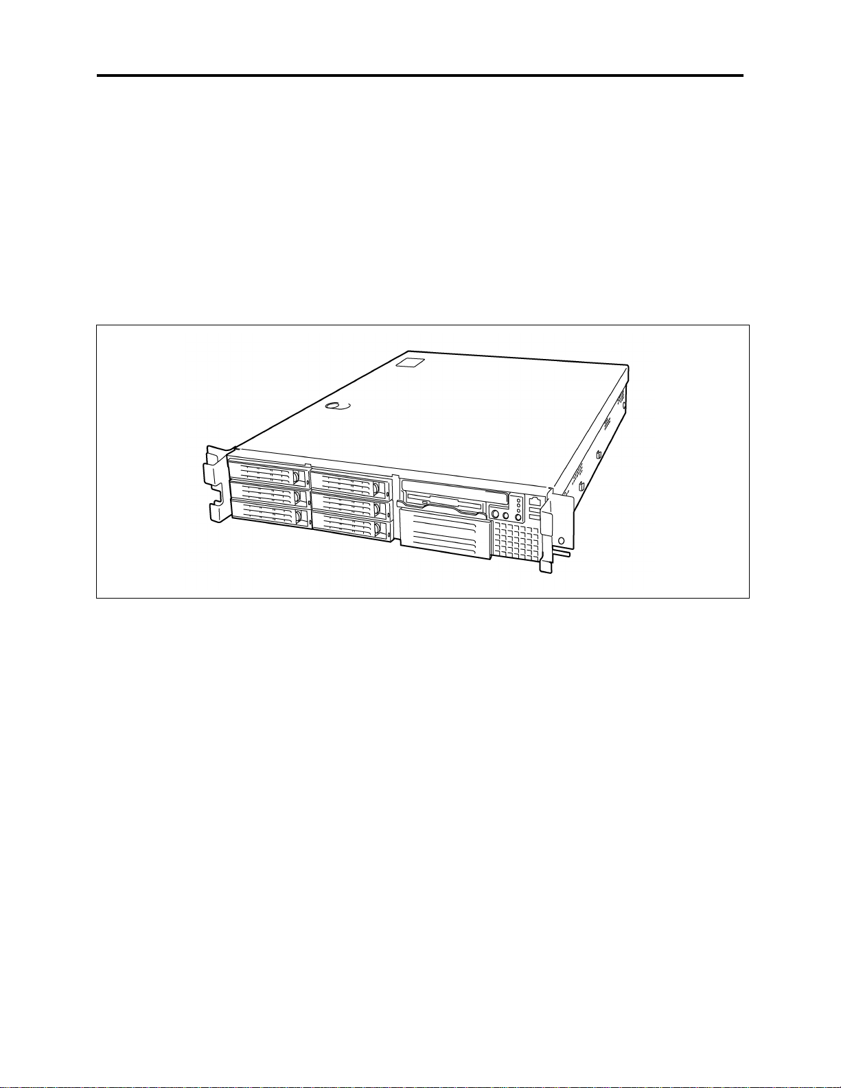
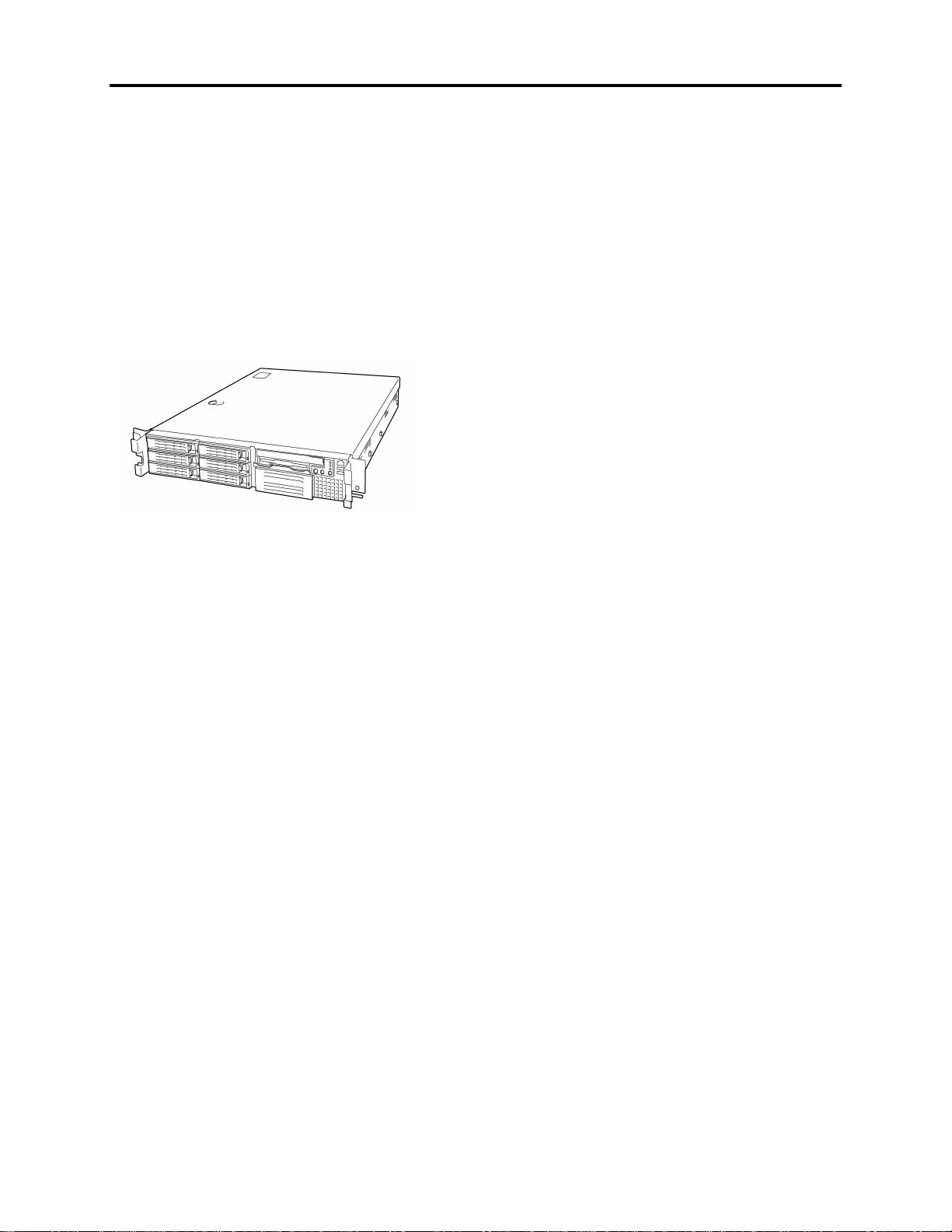
Your server is housed and available as a rack-mount system. Your server conveniently installs
into a standard EIA 19-inch rack assembly.
Your server includes a 3.5-inch diskette drive, a CD-ROM drive, six hot-swap SCSI hard disk
drive bays, and a removable media device bay. The hot-swap SCSI hard disk drive bays support
up to seven 1.0-inch SCSI hard disk drives that can be swapped in or out of the system without
powering it down, if RAID functionality is configured in the system.
Alternately, your server can be configured to include a 7th SCSI hard disk drive. This
configuration includes a removable media drive bay and seven hot-swap SCSI hard disk drive
bays. The removable media drive bay may be used for installation of a high-speed tape drive.
As application requirements increase, you can expand your server with an additional processor,
additional memory, add-in boards and peripheral devices: tape devices, CD-ROM, and hard disk
drives.
Page 11
System Overview 1-3
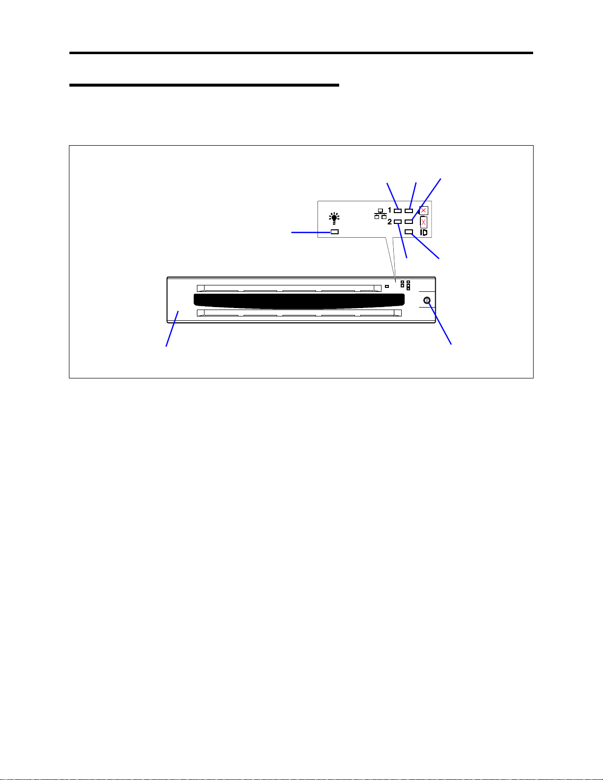
Front View with Front Bezel Closed
The following figure shows the location of the front system features viewable with the front
bezel closed.
456
3
4
1
1 Front bezel
The front bezel is a cover protecting the front devices during daily operation. A security key
is provided to lock the cover.
2Key slot
Insert the security key into this slot when unlocking the front bezel.
3 POWER lamp (green)
This lamp turns green when the power is turned on.
4 ACT lamp (green)
This lamp is on while the system is connected to the network. The number "1" on the icon
indicates LAN port 1, and the number "2" indicates LAN port 2.
5 STATUS lamp (green/amber) (on the front panel)
This lamp indicates the server status. The lamp is green during normal operation. The lamp
turns amber or flashes when the server enters an abnormal state.
6 DISK ACCESS lamp (green/amber)
This lamp is green during access to the internal hard disks. The lamp turns amber if any one
of the internal hard disk drives fail.
7 UID (Unit Identification) lamp (blue)
This lamp goes on when the UID switch is pressed. (The lamp also goes on when software
issues a command.)
7
2
Page 12
1-4 System Overview
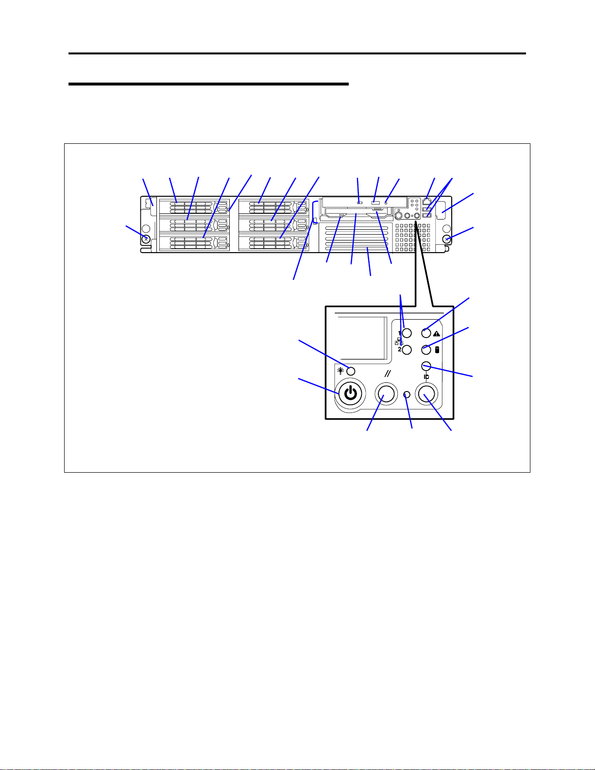
Front View with Front Bezel Removed
The following figure shows the location of the front system features viewable with the front
bezel removed.
2
3-0 3-1 3-2
1
4
3-3 3-4
5
11
12
-5
3
7
6-1 6-2 6-3 9
7-2
-1
8
7-3
11
10
2
1
11
11
11
151413
1 Thumbscrews (2)
These screws secure the server to the rack.
2 Handles (2)
Use these handles when dismounting/mounting the server from/in the rack.
3 SCSI hard disk bays
Each number following the bold-faced number indicates the SCSI ID.
4 DISK lamp (green/amber)
Hard disk lamp. Each hard disk lamp is green during access to the hard disk. The lamp
turns amber when the hard disk fails. The lamp flashes switching back and forth between
green and amber during build processing (disk array configuration).
5 Flex bay
A hard disk, CD-ROM, or floppy disk drive can be mounted in this bay. A CD-ROM or floppy
disk drive is mounted in the standard configuration. If a hard disk drive is mounted, SCSI ID8
is assigned to the bay.
6 CD-ROM drive
This drive reads data from CD-ROM media.
-1 Disk access lamp
6
-2 CD tray eject button
6
-3 Emergency hole (used to remove CD-ROM media when the server is powered down)
6
Page 13

7 3.5-inch floppy disk drive
This drive reads/writes data from/to the 3.5-inch floppy diskette.
-1 Disk access lamp
7
7-2 Disk slot
7-3 Eject button
8 Backup device bay
Mount an optional DAT or AIT drive in this bay.
9 Front serial port 2 connector
Connect a device having a serial interface to this connector.
10 USB connectors (2 ports)
Connect device compliant with the USB interface to the connectors. (Windows NT 4.0
requires a compliant driver.)
11 Lamps (See the previous figure for a description of these six lamps.)
12 POWER switch
Press this switch to turn the server on/off. Pressing the switch once turns on the power, and
the POWER lamp is lit. Pressing this switch again turns off the power. Once power is
applied to the server, pressing this switch for 4 seconds or more turns off the power.
13 Reset switch
Press this switch to reboot the server.
14 DUMP switch
Press this switch to dump system memory.
15 UID (unit ID) switch
Press this switch to turn the UID lamps on/off on the front and rear panels of the server.
Pressing the switch once turns the lamps on. Pressing this switch again turns the lamps off.
System Overview 1-5
Page 14
1-6 System Overview
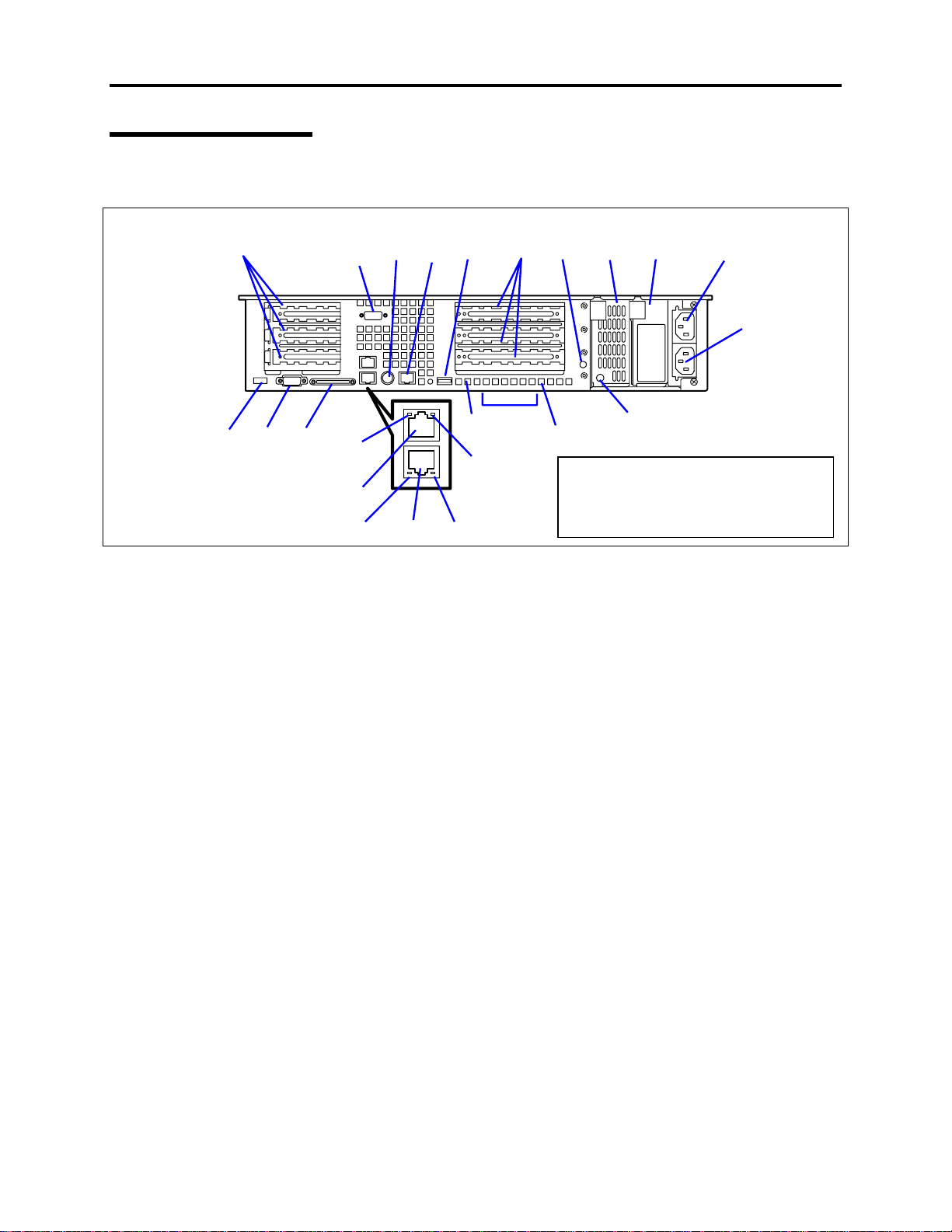
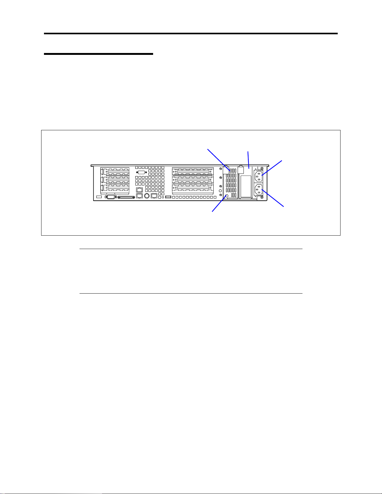
Rear View
The following figure shows the location of the features located at the rear of the system.
1
234
1 Low-profile PCI board extension slots
Mount low-profile type PCI boards these slots. The slots are designated 3C, 2C, and 1C.
2 USB connector
Connect a device compliant with the USB interface to this connector. (Windows NT 4.0
requires a compliant driver.)
3 Monitor connector
Connect the display monitor to this connector.
4 SCSI connector
Connect external SCSI devices to this connector.
5 Serial port 1 connector
Connect a device having a serial interface to this connector.
Note: The console of a management PC can be connected only to serial port 2. (Changes to
BIOS settings may be required) A leased line cannot be connected directly to this connector.
6 Mouse/keyboard connectors
Connect the mouse and keyboard to the connectors through the provided relay cables.
7 Rear serial port 2 connector
Connect device having a serial interface to this connector. BIOS settings may require
changes depending on the device to be connected.
A leased line cannot be connected directly to this connector.
8 Full-height PCI board extension slots
Mount PCI boards of the full-height type in the slots. The slots are designated 3B, 2B, and
1B.
5672 8201214 15
10
17
18-2
17 18-1 19
9
19
11
The "100BASE-TX/10BASE-T connector"
of (18) and the "serial port 2 connector" of
(7) have the same shape. Be careful not
to connect a cable to a wrong connector.
13
16
Page 15

9 STATUS lamp (green/amber) (on the real panel)
This lamp indicates the server status. The lamp is green during normal operation. The lamp
turns amber or flashes when the server enters an abnormal state.
10 POST lamps
The lamps are mounted on boards. They are on during POST after the power is turned on.
11 UID lamp (blue)
This lamp goes on when the UID switch is pressed. (The lamp also goes on when software
issues a command.)
12 Power supply unit (power supply slot 1)
This unit supplies power to the server.
13 AC POWER lamp
This lamp turns green and flashes when the server receives AC power from the power cord.
The lamp turns green when the server power switch is turned on, and it turns amber when a
power failure occurs.
14 Power supply unit extension slot (power supply slot 2)
An optional power supply unit may be installed in this slot. The slot , when empty, is
protected with the blank cover.
15 AC inlet (for the power supply unit provided as standard)
Connect the power cord to this socket when the power supply unit is mounted in power
supply slot 0.
16 AC inlet (for an additional power supply unit)
Connect the power cord to this socket when the power supply unit is mounted in power
supply slot 1.
17 LINK/ACT lamp (green)
This lamp indicates data activity on the LAN.
18 100BASE-TX/10BASE-T connectors
Connect network systems on the LAN to the connectors.
The number "1" following the bold-faced number indicates LAN port 1, and the number "2"
indicates LAN port 2.
19 Speed lamp (amber)
This lamp indicates the transmission speed of the LAN.
20 Hole for mounting the AC cord holder
Mount the provided AC cord holder as needed.
System Overview 1-7
Page 16
1-8 System Overview
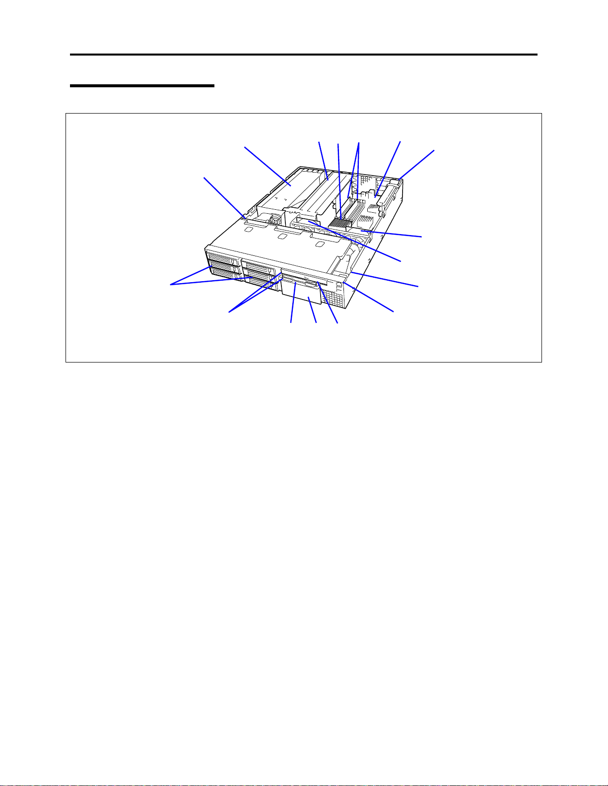
Internal View
2
1
15
14
1 SCSI backplane
2 Power supply unit
3 Riser card (for full-height boards)
4 Processor (mounted under the heat sink)
5 DIMM (Two DIMMs are mounted as standard in slots #1A and #1B.)
6 System board
7 Riser card (for only low-profile boards)
Cooling fans
8
(Each number following the bold-faced number indicates the corresponding fan name.)
8-1 System FAN 3
8-2 System FAN 1
9 Cover open sensor
10 Front LED board
11 CD-ROM drive
12 Backup device bay
13 Floppy disk drive
14 Flex bays
15 Disk bays
345 6
111213
10
8-2
7
-1
8
9
Page 17
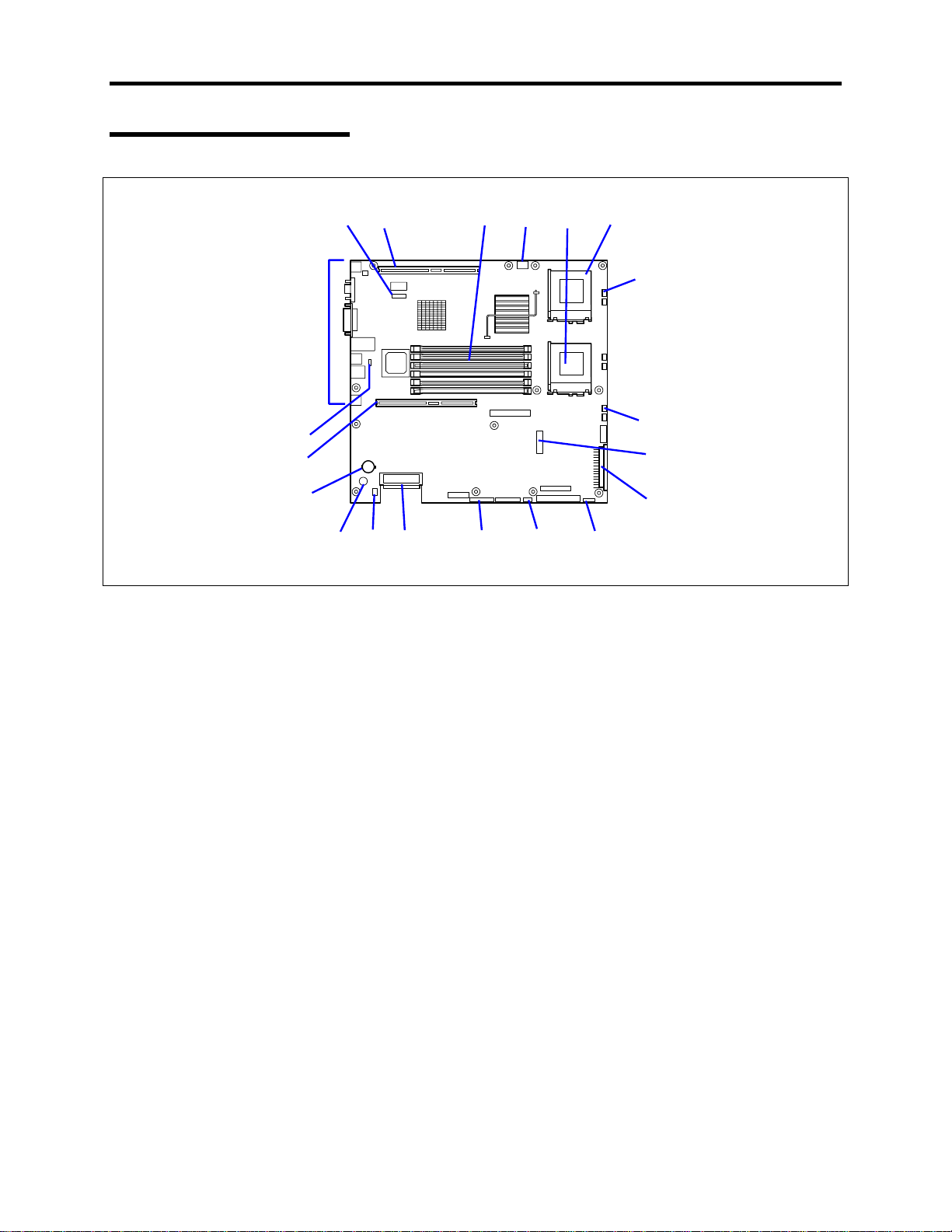
System Board
18
17
12 345 6
19
System Overview 1-9
-1
7
-2
7
8
16
1 ICMB connector
2 Connector for the PCI riser card
(For only low-profile boards. 66 MHz/64-bit)
3 DIMM sockets (for the interleave type)
(The sockets are called #3B, #2B, #1B, #3A, #2A, and #1A sequentially from top.)
4 Connector for the USB connector on the front panel
5 Processor #1 (CPU#1) socket
6 Processor #2 (CPU#2) socket
7 Cooling fan connectors
7-1 System FAN 3
-2 System FAN 1
7
8 Peripheral interface connector
9 Main power connector
10 Power signal connector
11 SCSI IPMB connector
12 Configuration jumper switch
13 Internal SCSI connector
14 Connector for the access lamp
(Connect the LED relay cable of an additional SCSI/disk array controller.)
15 Speaker
16 Lithium battery
17 Connector for the PCI riser card
(For full-height boards. 66 MHz/64-bit)
18 Jumper pin for selecting serial port specification (J6A2)
19 Connectors for external device
9
101112131415
Page 18

1-10 System Overview
STATUS INDICATORS
This section describes the server indicator lamps.
POWER Lamp ( )
The POWER lamp is on (green) when power is applied to the server and the power switch is on.
It is off if power is not applied to the server.
This server does not support the power saving mode.
STATUS Lamp ( )
Server STATUS lamps are located on the front and rear panels of the server. The STATUS lamps
are on (green) while the server is operating normally. If the STATUS lamps are off or turn amber
and flash it indicates that the server is in an abnormal state.
The table below provides more details on the system STATUS lamps.
NOTES:
!
If ESMPRO or the offline maintenance utility is installed, you can
confirm the cause of a failure by referring to the error log.
!
If shutdown processing can be performed through the operating
system, restart the system by performing normal shutdown processing.
If shutdown processing cannot be performed, restart the system by
resetting, forcibly turning the power off, or disconnecting and then
connecting the power cord.
Page 19

System Overview 1-11
STATUS lamp
indication
On (green) The server is operating normally. No action required.
Flashing
(green)
Off
On (amber)
Flashing
(amber)
Description Procedure
The server is operating with the
memory, CPU, or power supply unit
in degraded state.
Multiple correctable memory errors
were detected
The power is off. No action required.
POST is in progress.
A CPU error occurred.
A CPU temperature alarm was
detected. (Thermal-Trip)
A timeout occurred when the time
set for the watchdog timer arrived.
An uncorrectable memory error was
detected.
A PCI system error occurred.
A PCI parity error occurred.
A CPU bus error occurred.
A memory dump request is made. Wait until the memory dump is
A temperature alarm was detected. Clean the internal fans. Check that no
A voltage alarm was detected.
All the power supply units failed.
Either of the following was detected
in the redundant power
configuration:
AC power not supplied to one of
•
the two power supply units
Failure of one of the two power
•
supply units
A fan alarm was detected. Clean the internal fans. Check that no
A temperature warning was
detected.
CPU or memory error. Verify which
CPU or memory bank was disabled by
entering the F2 BIOS Setup menu and
replace the component as soon as
possible.
Multiple single-bit ECC errors
detected. Contact your field service
representative to arrange the
replacement of memory.
Wait. The STATUS lamp turns green
when POST is completed.
Turn the power off and then turn it on.
If the POST screen displays an error
message, note the message, and
contact your sales representative.
completed.
cables are obstructing the internal
airflow. If the error persists, contact
your field service representative.
Contact your sales representative.
Connect the power cord to supply
power. If the power supply unit is
faulty, contact your sales
representative.
cables are obstructing the internal
airflow. If the error persists, contact
your field service representative.
Clean the internal fans. Check that no
cables are obstructing the internal
airflow. If the error persists, contact
your field service representative.
Page 20

1-12 System Overview
DISK ACCESS Lamp ( )
The DISK ACCESS lamp indicates the status of the hard disk mounted in the 3.5-inch device
bay. The lamp flashes green each time access is made to the hard disk.
When the DISK ACCESS lamp turns amber, it indicates that a hard disk failure has occurred.
Check the hard disk lamp for the status of the failing hard disk.
If the DISK ACCESS lamp flashes off and on between green and amber or if the lamp turns
amber and flashes, it indicates that rebuild (reconstruction) processing is being performed for a
hard disk connected to the internal disk array controller.
IMPORTANT:
If a hard disk in the server is connected to a disk array
controller, the access lamp signal cable (provided with the server) must
be connected from the disk array controller to the system board.
ACT Lamp ( )
The ACT lamp is green while the server is connected to the LAN. The lamp flashes while the
server is accessed via the LAN (during transmission/reception of packets). The number next to
the icon indicates the network port number.
Disk access Lamp
The disk access lamp of the floppy disk drive or CD-ROM drive is on while the drive is
accessed.
Page 21
System Overview 1-13
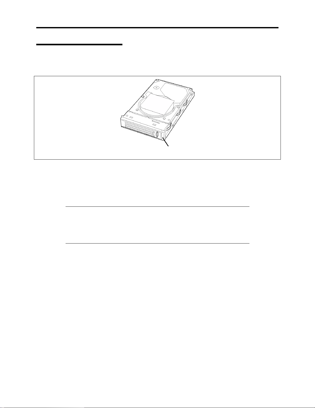
Hard Disk Lamp
The disk lamp mounted in the 3.5-inch device bay indicates the following, depending on the
status:
Lamp
!
Flashing (green)
The lamp indicates that the hard disk is being accessed.
!
On (amber)
The lamp indicates a failure of a hard disk mounted in disk array configuration.
NOTE:
Even if one of the hard disks fails in disk array configuration
(RAID1, RAID5, or RAID0+1), the server can continue operation.
However, replace the disk as soon as possible, and perform
reconstruction (rebuild) processing. (The failing disk can be replaced in
hot swap mode.)
!
Flashing, switching back and forth between green and amber
The lamp indicates that reconstruction (rebuild) processing is being performed for the
hard disk. (This flashing does not indicate a failure.) When a failing hard disk is
replaced in disk array configuration, the system automatically rebuilds the data (Autorebuild function). The lamp switches back and forth between green and amber during
rebuild processing.
The lamp goes off when the rebuild processing has completed. It turns a steady amber if
the rebuild processing fails.
Page 22
1-14 System Overview
IMPORTANT:
If the server is turned off during rebuild processing, the
processing is stopped. Restart the server, mount the new hard disk in hot
swap mode, and then perform rebuild processing again. Observe the
following notes on using the auto-rebuild function.
!
Do not turn the power off. (Once the power is turned off, the autobuild function does not start.)
!
When dismounting a failed hard disk drive, wait 90 seconds before
mounting the new hard disk drive.
!
Do not replace a failing hard disk while rebuild processing is being
performed on another hard disk.
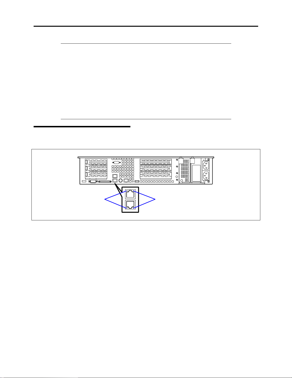
LAN Connector Lamps
There are two lamps for each of the two LAN ports (connectors) on the rear panel.
LINK/ACT lamps
!
LINK/ACT lamps
Speed lamps
Each LINK/ACT lamp indicates the status of the standard network port of the server.
While power is supplied to the server and HUB and the connection is correct, the lamp is
on (green). The lamp turns green and flashes while the network port is
transmitting/receiving data. (ACT)
If the lamp does not go on when the port is connected to the LAN port, check the
network cable. If the lamp does not go on and the network cable has checked out OK,
the network (LAN) controller may be faulty. In this case, contact your sales
representative.
!
Speed lamps
Each Speed lamp indicates that the communication mode of the server is activated with
either a network interface of 100BASE-TX or 10BASE-T . When the lamp is on
(amber), it indicates that the communication mode is activated with 100BASE-TX. Data
transfer rate is 100Mb/s. When the lamp is off, it indicates that the communication mode
is activated with 10BASE-T.Data transfer rate is 10Mb/s.
Page 23
System Overview 1-15
AC POWER Lamp
There is an AC POWER lamp for the power supply unit on the rear. The lamp turns green and
flashes when the power supply unit receives AC power from the power cord, which is connected
to the AC inlet.
The lamp turns green when the server power switch is turned on. If the lamp does not go on
when the server power switch is turned on or if it turns amber, the power supply unit is probably
faulty. In this case, contact your sales representative to replace the power supply unit.
Power supply slot 1 Power supply sl ot 2
AC inlet for
power
supply slot 1
AC inlet for
power
AC POWER lamp
supply slot 2
NOTE:
If one power supply unit fails while an optional power supply is
installed, the system can continue operation with the other power supply
unit. (Redundant function) The failing power supply unit can be
replaced in hot swap mode (with the power on) without the system being
powered down.
Page 24
1-16 System Overview
STANDARD FEATURES
High performance Expandability
! Intel Pentium III Processor
(1GHz/1.26GHz-S)
! High-speed 100BASE-TX/10BASE-T
interface (100Mbps/10M bps support ed)
! High-speed disk access
(Ultra160 SCSI x 2)
! High-speed memory access (133MHz,
ECC, registered, PC/133 compliant, 72bit, 68-pin, 3.3V)
! Three full-length, full-height 64-bit/66-
MHz PCI riser slots and three low profile
64-bit/66-MHz riser slots
! Large memory of up to 6 GB
! Seven hot-swap SCSI hard disk drive
bays
! Up to two multi-processors are available
for upgrade.
! One backup file bay
! Flex bay
! USB interface (A USB-support driver is
required.)
! Two network ports
High-reliability Many Available Features
! Memory monitoring feature (1-bit error
correction/ 2-bit error detection)
! CPU/memory degradation feature
(logical isolation of a failed device)
! Bus parity error detection
! Temperature detection
! Error notification
! Internal fan monitoring feature
! Internal voltage monitoring feature
! Auto-rebuild feature (optional, hot-
swappable)
! BIOS password feature
! Mechanical security lock
! Redundant power supply (hot-swap)
Management Utilities Easy and Fine Setup
! NEC ESMPRO
! NEC Management Workstation
Application (NEC MWA)
Maintenance Features
! Off-line Maintenance Utility
! Memory dump feature using the DUMP
switch
! Graphic accelerator "RAGE XL" support
! Bootable CD-ROM (no emulation mode)
format support
! POWER switch mask
! Software power-off
! Remote power-on feature
! AC-LINK feature
! Baseboard Management Controller
(BMC)
! Consoleless feature
Self-diagnosis
! Power On Self-Test (POST)
! Test and Diagnosis (T&D)
! NEC EXPRESSBUILDER (system setup
utility)
! Configuration Parameter Diskette Creator
! SETUP (BIOS setup utility)
! SCSISelect (SCSI device utility)
Page 25

System Overview 1-17
Power Supplies
The power supply consists of the power supply bay and one power supply module. A second
power supply module can be purchased to provide a redundant, 1+1 system. With either
configuration, the power supply provides 350 watts of power and is designed to minimize EMI.
The power subsystem supports implementation of remote management features including remote
enable that permits power to be activated from a variety of sources.
Peripheral Bays
Your server supports a variety of standard PC AT-compatible peripheral devices. The chassis
includes these peripheral bays:
!
An optional removable media front panel bay for mounting a half-height 3.5-inch
peripheral device such as an optional tape drive.
!
Depending on your configuration, your server includes either six or seven hot-swap
SCSI hard disk drive bays for mounting hard disk drives installed in easily removable
drive carriers.
NOTE: The hot-swap SCSI hard disk drive bays contain a hot-swap back
plane that require an 80-pin single connector attachment (SCA)
connector on the drives that you install.
– The flex bay can be used with either the standard CD-ROM/FDD module or a seventh
hot swappable SCSI HDD.
The CD-ROM/FDD module may only be inserted or removed from the flex bay when
system power is turned off. The CD-ROM/FDD module is NOT hot swappable. The
standard 3.5-inch diskette drive supports 720 KB and 1.44 MB diskette media.
– The chassis includes two 80-mm non-hot-swappable system fans for cooling the
processor(s), hard drives, and add-in cards. The system fans are mounted in a fan
assembly located in the middle of the chassis to pull cooling air through the chassis.
The power supply contains a single fan for cooling.
Page 26

1-18 System Overview
SAF-TE LOGIC
NOTE: SAF-TE Logic is in systems that include the hot-swap SCSI disk
drive cage. SAF-TE Logic i s not available in systems that include the
standard SCSI disk drive cage.
The SCSI backplane includes SAF-TE (SCSI Accessed Fault Tolerant Enclosure) logic that
provides an interface to the disk subsystem that supports status signals, hot swapping drives, and
enclosure monitoring.
The transport mechanism for the standardized alert detection and status reporting is the SCSI
bus. Disk drives, power supplies, cooling fans, and temperature are continually monitored and
the conditions then reported over the SCSI bus to the system. When used with RAID
management software the user can be alerted of impending or imminent disk conditions
requiring attention. This allows the user to react to conditions that could normally go unnoticed
until data loss.
SYSTEM BOARD FEAT URES
The following subsections describe the system board major components.
Processor
The system board accommodates one or two Intel Pentium III processors with 512k cache in the
FC-PGA2 package. This processor uses the .13 micron technology and offers advanced
performance. The processor external interface operates at a maximum of 133 MHz.
Memory
The system board contains six 168-pin DIMM slots each supporting 72-bit ECC (64-bit main
memory plus ECC) registered SDRAM DIMMs (PC-133 compatible). Memory is two-way
interleaved and partitioned in three banks. You may install a minimum of 256 MB (128MB × 2)
andasmuchas6GB.
The controller automatically detects, sizes, and initializes the memory arra y, depending on the
type, size, and speed of the installed DIMMs, and reports memory size and allocation to the
server via configuration registers.
NOTE:
system board.
Contact your sales representative or dealer for a current list of approved
memory modules.
Use DIMMs that have been tested for compatibility with the
Page 27

System Overview 1-19
PCI Riser Slots
The system board has two PCI riser slots, each capable of supporting 64-bit/66-MHz PCI riser
cards.
PCI features:
!
Bus speed up to 66 MHz
!
32 bit memory addressing
!
5 V/3.3 V signaling environment
!
Burst transfers of up to 512 Mbps
!
8, 16, 32, or 64-bit data transfers
!
Plug and Play ready
!
Parity enabled.
Video
The system board uses an ATI RAGE XL PCI graphics accelerator with 8 MB of video SDRAM
that supports all standard IBM VGA modes. The embedded SVGA video subsystem supports:
!
Pixel resolutions up to 1600 x 1200 under 2D and 1024 x 768 under 3D
!
CRT and LCD monitors up to 100 Hz vertical refresh rate
The system board supports disabling of the onboard video through the BIOS setup menu or when
a plug in video card is installed in any of the PCI slots.
SCSI Controller
The system board includes an embedded Adaptec AIC-7899W controller providing dual
Ultra160 Low Voltage Differential ( LVD) SCSI channels.
The SCSI bus is terminated on the system board with active terminators that cannot be disabled.
The onboard device must always be at one end of the bus. The device at the other end of the
cable must also be terminated. LVD devices generally do not have termination built-in and need
to have a termination source provided. Non-LVDs devices generally are terminated through a
jumper or resistor pack on the device itself.
Page 28

1-20 System Overview
Network Controller
NOTE:
To ensure EMC product regulation compliance, the system must
be used with a shielded LAN cable.
The system board uses two Intel ® 82550PM Fast Ethernet Controllers and supports two
10Base-T/100Base-TX network subsystems.
The 82550 PM controller supports the following features:
!
32-bit PCI, CardBus master interface
!
Integrated IEEE 802.3 10Base-T and 100Base-TX compatible PHY
!
IEEE 820.3u auto-negotiation support
!
Chained memory structure similar to the 82559, 82558, 82557 and 82596
!
Full duplex support at both 10 Mbps and 100 Mbps operation
!
Low power +3.3 V device
!
IP checksum off-loading.
On the system board, NIC 1 can be used as both a network interface and server management
interface.
NIC Connector and Status LEDs
The 82550 controller drives LEDs on the network interface connector that indicate link/activity
on the LAN and 10- or 100-Mbps operation. The green LED indicates network connection when
on and TX/RX activity when blinking. The yellow LED indicates 100-Mbps operation when lit.
Page 29

Network Teaming Features
System Overview 1-21
NOTE:
Using both on-board NICs in a team does not allow the use of
NIC 1 for server management access. To support both network teaming
features and server management features, a third NIC must be added and
teamed to NIC 2.
The network controller provides several options for increasing throughput and fault tolerance
when running Windows NT 4.0, Windows 2000, NetWare 4.2 or newer:
!
Adapter Fault Tolerance (AFT) - provides automatic redundancy for your adapter. If the
primary adapter fails, the secondary takes over. AFT works with any hub or switch.
!
Adaptive Load Balancing (ALB) - creates a team of 2 - 8 adapters to increase
transmission throughput. Also includes AFT. Works with any 10Base-TX or 100BaseTX switch.
!
Fast EtherChannel (FEC) or Intel ® Link Aggregation - creates a team of up to 8
adapters to increase transmission and reception throughput. Also includes AFT. Requires
a FEC-enabled switch.
To set up an option, read the instructions in the Windows NT 4.0 or NetWare readme files.
General Configuration Notes
Windows NT versions prior to 4.0 do not support Adapter Teaming options.
1.
Adapter Teaming options require NT 4.0 with Service Pack 4.0 or Service Pack 3.0 and
2.
the Windows Hot Fix .
In Windows NT, teaming options cannot be implemented on adapters that have been
3.
configured for VLANs. NetWare can support teaming options and VLANs on the same
adapters.
Adapter Fault Tolerance
Adapter Fault Tolerance (AFT) is a simple, effective, and fail-safe approach to increase the
reliability of server connections. AFT gives you the ability to set up link recovery to the server
adapter in case of a cable, port, or network interface card failure. By assigning two server
adapters as a team, AFT enables you to maintain uninterrupted network performance.
AFT is implemented with two server adapters: a primary adapter and a backup, or secondary,
adapter. During normal operation, the backup will have transmit disabled. If the link to the
primary adapter fails, the link to the backup adapter automatically takes over.
Page 30

1-22 System Overview
Preferred Primary Adapter
With multiple adapters installed, you can specify one as the Preferred Primar y adapter. For
example if you have a server with a PRO/1000 server adapter as the primary adapter and a
PRO/100+ adapter as the secondary, you could configure the PRO/1000 server adapter to be the
preferred primary. In this scenario, if the PRO/1000 server adapter fails, the PRO/100+ will take
over. Then when the PRO/1000 server adapter is replaced, it will automatically revert to being
the primary adapter in the team.
If a Preferred Primary is not selected, PROSet will attempt to select the best adapter, based on
adapter model and speed.
Mixed Adapter Teaming
AFT supports up to eight server adapters per team, in any mix.
Adaptive Load Balancing
Adaptive Load Balancing (ALB) is a simple and efficient way to increase your server’s transmit
throughput. With ALB you group server adapters in teams to provide an increased transmit rate
(up to 8 Gbps) using a maximum of eight adapters. The ALB software continuously analyzes
transmit loading on each adapter and balances the rate across the adapters as needed. Adapter
teams configured for ALB also provide the benefits of AFT. Receive rates remain at 100 Mbps or
1 Gbps depending on the primary adapter’s capability.
To use ALB, you must have 2-8 server adapters installed in your server or workstation and
linked to the same network switch.
Page 31

System Overview 1-23
Keyboard and Mouse
The keyboard/mouse controller is PS/2-compatible. The server may be locked automatically if
there is no keyboard or mouse activity for a predefined len gth of time. Once the inactivity
(lockout) timer has expired, the keyboard and mouse do not respond until the previously stored
password is entered. A Y-cable is included with your server and can be used if both a PS/2
mouse and keyboard are required at the same time. The keyboard and mouse are ordered
separately.
RJ-45 Serial Port
The rear RJ-45 serial port is a fully functional COM port that supports any standard serial device
and provides support for serial concentrators, which typically support RJ45 serial connectors. For
server applications that use a serial concentrator to access the server management features of the
system board, a standard 8-pin CAT-5 cable from the serial concentrator is plugged directly into
the rear RJ45 serial port. The 8 pins of the RJ45 connector can be configured to match either of
two pin-out standards used by serial port concentrators. To accommodate either standard, the
J6A2 jumper block located directly behind the rear RJ45 serial port must be jumpered
appropriately according to which standard is desired.
See Chapter 2 for detail explanation.
ACPI
The system board supports the Advanced Configuration and Power Interface (ACPI) as defined
by the ACPI 1.0 and PC97 specifications. An ACPI aware operating system can put the system
into a state where the hard drives spin down, the system fans stop, and all processing is halted.
However, the power supply will still be on and the processors will still be dissipating some
power, so the power supply fans will still run.
The system board supports sleep states s0, s1, s4, and s5:
!
s0: Normal running state.
!
s1: Processor sleep state. No context will be lost in this state and the processor caches
will maintain coherency.
!
s4: Hibernate or Save to Disk: The memory and machine state are saved to disk.
Pressing the power button or other wakeup event will restore the system state from the
disk and resume normal operation. This assumes that no hardware changes have been
made to the system while it was off.
!
s5: Soft off: Only the RTC section of the CSB and the BMC are running in this state. No
context is saved by the OS or hardware.
IMPORTANT:
disconnected.
The system is off only when the AC power cord is
Page 32

1-24 System Overview
System Board Management Controller (BMC)
Server management is concentrated in the System Board Management Controller (BMC). The
BMC and associated circuitry are powered from a 5Vdc standby voltage, which remains active
when system power is switched off, but the ac power source is still on and connected.
The BMC supports the Management Workstation Application (NEC MWA), which allows
remote server management via a modem or direct connection to a manager system. Events
monitored by the manager system include over-temperature and over-voltage conditions, fan
failure, or chassis intrusion.
Information on MWA may be found on the EXPRESSBUILDER CD-ROM included with your
server.
One major function of the BMC is to autonomously monitor system management events, and log
their occurrence in the nonvolatile System Event Log (SEL). The events being monitored
include over-temperature and over-voltage conditions, fan failure, or chassis intrusion. To enable
accurate monitoring, the BMC maintains the nonvolatile Sensor Data Record (SDR), from which
sensor information can be retrieved. The BMC provides an ISA host interface to SDR sensor
information, so that software running on the server can poll and retrieve the server's current
status.
The BMC performs the following:
!
Monitors system board temperature and voltage
!
Monitors processor presence and controls Fault Resilient Boot (FRB)
!
Detects and indicates baseboard fan failure
!
Manages the SEL interface
!
Manages the SDR Repository interface
!
Monitors the SDR/SEL timestamp clock
!
Monitors the system management watchdog timer
!
Monitors the periodic SMI timer
!
Monitors the event receiver
!
Controls secure mode, including video blanking, diskette write-protect monitoring, and
front panel lock/unlock initiation
!
Controls Wake On LAN via Magic Packet support.
Page 33

System Overview 1-25
DEGRADATI O N FEAT URE
The degradation feature automatically isolates a failed DIMM or processor to assure continuous
operation of the server when the POST (Power On Self-Test, self-diagnosis program after power
on) detects such a DIMM or processor.
NOTE:
The degradation feature is only available when at least two
DIMMs or processors are installed.
Failed DIMMs and processors may be identified on the screen that the POST displays, or with
the BIOS setup utility of the server, "SETUP." They may also be identified on the system that
has the ESMPRO installed.
REMOTE POWER-ON FEATURE (WAKE ON LAN)
The remote power-on function turns on the server through a network. It sends a special packet
from the management computer to a remote server to turn it on if the server is off-powered.
To enable this feature, you must select "Enabled" for "Wake On LAN" in the Wake On Event of
the System Hardware menu of the BIOS setup utility, "SETUP." (See Chapter 3.)
The remote power-on feature is not available in the following cases. Press the POWER switch
once to start the OS, and turn off the server in an appropriate procedure.
!
Abnormal previous system shut-down
!
No power supply to the server (due to turned-off breaker, disconnected power cord,
power blackout, etc.)
AC-LINK FEATURE
When the power cord of the server is connected to an uninterruptible power supply (UPS) unit,
the server supports the power linkage feature that enables control over the power supply from the
UPS to the server. The AC-LINK feature can be enabled or disabled with the System Hardware
menu of the BIOS setup utility, "SETUP." (See Chapter 3.)
Page 34

1-26 System Overview
SYSTEM SECURITY
To help prevent unauthorized entry or use of the system, the system includes a full lockable front
bezel and Server Management software that monitors the front bezel intrusion switch.
Security with Mechanical Locks and Monitoring
To unlock the bezel, insert the key in the lock and turn the lock counterclockwise until it stops
(about a quarter turn). The bezel is now unlocked and can be opened again.
To lock the bezel, insert the key in the lock. Turn the lock clockwise until it stops (about a
quarter turn). The bezel is now locked and cannot be opened.
Software Locks via the BIOS Setup Utility
The BIOS Setup Utility provides a number of security features to prevent unauthorized or
accidental access to the system. Once the security measures are enabled, you can access the
system only after you enter the correct password(s). For example:
!
Enable the keyboard lockout timer so that the server requires a password to reactivate
the keyboard and mouse after a specified time out period–1to120minutes.
!
Set and enable a supervisor password.
!
Set and enable a user password.
!
Set secure mode to prevent keyboard or mouse input and to prevent use of the front
panel reset and power switches.
!
Activate a hot key combination to enter secure mode quickly.
!
Disable writing to the diskette drive when secure mode is set.
!
Disable access to the boot sector of the operating system hard disk drive.
Page 35

System Overview 1-27
Using Passwords
You can set either the user password, the supervisor password, or both passwords. If only the
user password is set, you:
!
Must enter the user password to enter BIOS Setup.
!
Must enter the user password to boot the server if Password on Boot is enabled in either
the BIOS Setup.
!
Must enter the user password to exit secure mode.
If only the supervisor password is set, you:
!
Must enter the supervisor password to enter BIOS Setup.
!
Must enter the supervisor password to boot the server if Password on Boot is enabled in
either the BIOS Setup.
!
Must enter the supervisor password to exit secure mode.
If both passwords are set, you:
!
May enter the user password to enter BIOS Setup. However, you will not be able to
change many of the options.
!
Must enter the supervisor password if you want to enter BIOS Setup and have access to
all of the options.
!
May enter either password to boot the server if Password on Boot is enabled in either the
BIOS Setup.
!
May enter either password to exit secure mode.
Secure Mode
Configure and enable the secure boot mode by using the BIOS Setup. When secure mode is in
effect:
!
You can boot the server and the operating system will run, but you must enter the user
password to use the keyboard or mouse.
!
You cannot turn off system power or reset the server from the front panel switches.
Secure mode has no effect on functions enabled via remote server management or power control
via the watchdog timer.
Taking the server out of secure mode does not change the state of system power. That is, if you
press and release the power switch while secure mode is in effect, the system will not be
powered off when secure mode is later removed. However, if the front panel power switch
remains depressed when secure mode is removed, the server will be powered off.
Page 36

1-28 System Overview
Summary of Software Security Features
The table below lists the software security features and describes what protection each offers. In
general, to enable or set the features listed here, you must run the BIOS Setup and go to the
Security Subsystem Group, menu. The table also refers to the Setup utility.
Software Security Features
Feature Description
Secure mode How to enter secure mode:
Setting and enabling passwords automatically places the system in
•
secure mode.
If you set a hot-key combination (through Setup), you can secure the
•
system simply by pressing the key combination. This means you do not
have to wait for the inactivity time-out period.
When the system is in secure mode:
The server can boot and run the operating system, but mouse and
keyboard input is not accepted until the user password is entered.
At boot time, if a CD is detected in the CD-ROM drive or a diskette in
drive A, the system prompts for a password. When the password is
entered, the server boots from CD or diskette and disables the secure
mode.
If there is no CD in the CD-ROM drive or diskette in drive A, the server
boots from drive C and automatically goes into secure mode. All enabled
secure mode features go into effect at boot time.
To leave secure mode: Enter the correct password(s).
Disable writing to
diskette
Set a time out
period so that
keyboard and
mouse input are not
accepted.
Also, screen can be
blanked, and writes
to diskette can be
inhibited
Control access to
using the BIOS
Setup: set
supervisor
password
Control access to
the system other
than BIOS Setup:
set user password
In secure mode, the server will not boot from or write to a diskette unless
a password is entered.
To write protect access to diskette whether the server is in secure mode
or not, use the Setup main menu, Floppy Options, and specify Floppy
Access as read only.
Specify and enable an inactivity time out period of from 1 to 120 minutes.
If no keyboard or mouse action occurs for the specified period, attem pted
keyboard and mouse input will not be accepted.
The monitor display will go blank, and the diskette drive will be write
protected (if these security features are enabled through Setup).
To resume activity: Enter the correct password(s).
To control access to setting or changing the system configuration, set a
supervisor password and enable it through Setup.
If both the supervisor and user passwords are enabled, either can be
used to boot the server or enable the keyboard and/or mouse, but only
the supervisor password will allow Setup to be changed.
To disable a password, change it to a blank entry or press CTRL-D in the
Change Password menu of the Supervisor Password Option menu found
in the Security Subsystem Group.
To clear the password if you cannot access Setup, change the Clear
Password jumper (see Chapter 3).
To control access to using the system, set a user password and enable it
through Setup.
To disable a password, change it to a blank entry or press CTRL-D in the
Change Password menu of the User Password Option menu found in the
Security Subsystem Group.
To clear the password if you cannot access Setup, change the Clear
Password jumper (see Chapter 3).
Page 37

Feature Description
Boot without
keyboard
Specify the boot
sequence
The system can boot with or without a keyboard. During POST, before the
system completes the boot sequence, the BIOS automatically detects and
tests the keyboard if it is present and displays a message.
The sequence that you specify in setup will determine the boot order. If
secure mode is enabled (a user password is set), then you will be
prompted for a password before the server fully boots. If secure mode is
enabled and the “Secure Boot Mode” option is also enabled, the server
will fully boot but will require a password before accepting any keyboard
or mouse input.
System Overview 1-29
Page 38

1-30 System Overview
EXPRESSBUILDER
The CD-ROM that comes with the server contains a setup utility called "EXPRESSBUILDER."
When you have first installed the server or append features to the server, use the
EXPRESSBUILDER to set up your server.
Refer to the EXPRESSBUILDER User’s Guide, located on your EXPRESSBUILDER CDROM,
for details.
IMPORTANT:
Do not use the EXPRESSBUILDER for any other
computers than the server, nor other Express5800 series servers than the
one that EXPRESSBUILDER is provided for. Not following this
instruction may cause failures.
The major functions of the EXPRESSBUILDER are:
!
To install the OS.
It installs an operatin g system.
!
To diagnose the system.
It diagnoses the server.
!
To create a support disk.
It copies utilities in the EXPRESSBUILDER CD-ROM into a floppy disk to launch
them from the floppy disk.
!
To update the Windows System*
It updates the several resources of Microsoft Windows 2000 or Windows NT.
!
To install the utilities
It install the management utilities of ESMPRO and MWA.
!
To read the online documents*
It opens the online document files (".PDF" files).
* These functions are available under Windows system.
NOTE:
Some features among those listed above can be used from the
remote computer via cross cable, modem, or LAN (consoleless feature).
See Appendix B for details.
Page 39

System Overview 1-31
NEC ESMPRO
The ESMPRO is server management software that runs on the OS. The ESMPRO includes the
ESMPRO Manager for the server monitoring terminal and the ESMPRO Agent for the server.
NOTE:
configuration and setups with the ESMPRO, refer to the ESMPRO
User’s Guide included on the ESMPRO CDROM.
Available functions of the ESMPRO depend on the OS you install. Ask
your sales agent for details.
For details of major functions of the ESMPRO, system
OFF-LINE MAINTENANCE UTILITY
The Off-line Maintenance Utility is used for proactive maintenance and fault analysis of the
server. Normally this utility is used by the maintenance engineer.
Refer to Chapter 6 for details.
SYSTEM DIAGNOSTIC UTILITY
The system diagnostic utility contained in the EXPRESSBUILDER is useful to prevent the
hardware failures. Refer to the EXPRESSBUILDER User’s Guide, located on your
EXPRESSBUILDER CDROM, for details.
NEC MANAGEMENT WORKST ATION APPLICATION (NEC MWA)
The Management Workstation Application (MWA) is an application program for remote
management of the server from a system management computer (a computer with the ESMPRO
Manager running) through a network.
For more information on MWA, refer to the Management Workstation Application User’s Guide
included on the ESMPRO CDROM.
Page 40

1-32 System Overview
USING YOUR SERVER
This section describes basic operations of the server including how to use devices such as the
floppy disk drive and the CD-ROM drive.
Front Bezel
Remove the front bezel to power on/off the server, to access the floppy disk drive, CD-ROM
drive, and a removable media device, and to install/remove hard disks to the 3.5-inch device
bays.
IMPORTANT:
To open the front door, you must unlock the door with the
provided security key.
Installing or Removing the Front Bezel
When turning the power of the server on/off, accessing to the floppy disk drive, CD-ROM drive,
or a removable media device, or installing or removing a hard disk from the 3.5-inch device bay,
first remove the front bezel.
IMPORTANT:
The front bezel can be opened only when you unlock it by
using the security key.
Insert the security key into the key slot and turn the key to t he front bezel side with it
1.
pressed lightly to release the lock.
Unlock Lock
Hold the right end of the front bezel lightly, and pull it towards you.
2.
Page 41

System Overview 1-33
Slide the front bezel to the left to remove the tab from the frame and then remove the
3.
front bezel from the server.
To install the front bezel, latch the tab at the left side of the front bezel on the server
4.
frame. After the installation, lock the front bezel for security.
Frame
Tab
Page 42

1-34 System Overview
POWER Switch
Use the POWER switch to turn on/off the server.
Power On
Press the POWER switch on the front of the server chassis.
The POWER lamp lights in green.
POWER lamp
POWER switch
IMPORTANT:
!
If the power cord is connected to a power control device such as a
UPS (Uninterruptible Power Supply), make sure that the power
control device is powered up.
!
When power is applied to the server, an initial diagnosis of the
hardware starts. The POWER switch does not work while in
diagnosis. Wait for about 10 seconds after power up, then press the
POWERswitchtoturntheserveroff.
!
Do not turn off the server until characters following the "NEC" logo
appear on the screen.
Page 43

System Overview 1-35
POST
POST (Power On Self-Test) is the server's self-diagnostic program stored in system memory.
When you power on the server, the system automatically runs POST to check the system board,
ECC memory module, CPU module, keyboard, and mouse. POST also displays messages from
the BIOS Setup Utility, such as the start-up message, while in progress.
With the factory setup of the server, the logo appears on the display unit while POST is in
progress. (To display the POST check results, press Esc.)
NOTE:
You can set the POST check results to appear on the display unit
without pressing Esc. To do so, select "Enabled" for "Boot-time
Diagnostic Screen" under the Advanced menu of the BIOS Setup Utility.
It is not necessary to check the POST check results. Check messages that POST displays when:
!
You use the server for the first time.
!
The server appears to fail.
!
The server beeps for many times between power-on and OS start-up.
!
An error message appears on the display unit.
Page 44

1-36 System Overview
POST Execution Flow
The following describes the progress of POST in chronological order.
IMPORTANT:
!
Do not make key entries or perform mouse operations while POST is
in progress.
!
Some system configurations may display the message "Press Any
Key" to prompt a key entry. This message is driven by the BIOS of an
installed optional board. Make sure to read the manual that is
included with the optional board before you make any key entry.
!
Powering on the server after you installed or removed an optional PCI
board or moved it to another slot, may display the massage that
indicates incorrect board configuration and suspend POST.
In such a case, press F1 to continue POST. Board configuration can
be made using the utility described later in this chapter.
After a few seconds from power-on, POST starts checking system memory. The count
1.
message of the basic and expansion memory app ears at top left on the display unit
screen. The memory check may takes a few minutes to complete depending on the
memory size of the server. Also, it may take approximately one minute for the screen
display to appear after rebooting the server.
Some messages appear upon completion of the memory check. These messages appear
2.
to indicate that the system has detected the CPU, keyboard, and mouse.
After a few seconds, POST displays the following message prompting you to launch the
3.
BIOS setup utility, SETUP, stored in the system memory of the server. This message
appears at bottom left on the screen.
Press <F2> to enter SETUP, Press <F12> to Network
Launch the BIOS setup utility when you need to change the settings to meet the
requirements for the server. As long as the above message is not displayed with an error
message, you don't have to launch the utility. (Ignore the message. POST will
automatically proceed.)
To launch the SETUP utility, press F2 while the above message is displayed. See
Chapter 3 for setup and parameters.
The server automatically restarts POST all over again when you exit the SETUP utility.
Press F12 to start the operating system from the network drive.
Page 45

System Overview 1-37
POST then detects the internal SCSI controller and display the massage prompting you
4.
to launch the SCSI device utility. (Ignore the message. POST will automatically
proceed a few seconds later.)
Press <Ctrl> <A> for SCSISelect(TM) Utility!
To launch the SCSI device utility, press Ctrl and A. See Chapter 3 for setup and
parameters.
You need to use the SCSI device utility when:
– You installed an SCSI device in a 5.25-inch device bay.
– You connected an external SCSI device.
– You changed internal SCSI device connections of the server.
The server automatically restarts POST all over again when you exit the SCSI device
utility.
If more than one SCSI controller board is installed on the PCI bus of the server, the
system detects the boot devices in order of the PCI slots 1C, 2C, and 3C (for low-profile
boards), and then the PCI slots 1B, 2B, and 3B (for full-height boards). The system
starts detecting the slots in each PCI riser card in ascending order of the slot numbers,
and displays the message indicating activation of the SCSI BIOS SETUP utility. If the
system drive is to be connected to a SCSI controller board (e.g., a disk array controller),
connect it to the PCI slot 1C (for a low-profile board).
POST displays SCSI ID numbers used by the connected SCSI devices on the screen.
5.
If an optional disk array controller is installed, the system displays the message
6.
prompting you to activate the disk array BIOS SETUP utility. (The start message and
operation may vary depending on the mounted board.)
For details, see the manual provided with the board or the online document on the
EXPRESSBUILDER CD provided with the server.
If you set a password using the BIOS setup utility, SETUP, the password entry screen
7.
appears upon successful completion of POST.
Up to three password entries will be accepted. Three incorrect password entries disable
the server to boot. In such a case, turn off the power and wait about ten seconds before
turning on to boot the server.
IMPORTANT:
The OS starts when POST completes.
8.
Do not set a password before installing an OS.
Page 46

1-38 System Overview
POST Error Messages
When POST detects an error, it displays an error message on the display unit screen. See
Chapter6forPOSTerrorcodes.
IMPORTANT:
Take a note on the messages displayed before consulting
with your service representative. Alarm messages are useful information
for maintenance.
Power Off
Follow the procedure below to power off the server. If the power cord of the server is connected
to a UPS, refer to the manual that comes with the UPS or the manual for the application that
controls the UPS.
IMPORTANT:
Always allow POST to complete before turning off the
server.
Shut down the OS.
1.
Press the POWER switch on the front of the server.
2.
The POWER lamp goes off.
Power off peripheral devices.
3.
Page 47

System Overview 1-39
Identification of Servers ~ UID Switch ~
An "UID (unit ID) lamp" is provided on the front panel and rear panel. If more than one server
is mounted in a single rack, the lamp identifies the server you are maintaining.
The UID lamp goes on when the UID (unit ID) switch on the front panel is pressed. It goes off
when the switch is pressed again.
Maintenance from the rear of the rack has to be carried out in a dark, narrow space. The
interface cable of a server or power supply unit in normal state may be disconnected by accident
in this situation. To prevent this problem, you should start maintenance after confirming the
target server by using the UID switch.
UID lamp
UID switch
UID lamp (Visible through the clearance between
the frame and the lamp on the system board)
Page 48

1-40 System Overview
Floppy Disk Drive
The server is includes a 3.5-inch floppy disk drive.
The server supports the following 3.5-inch floppy disks:
!
2HD floppy disk (double-sided high-density track type)
Stores data of 1.44MB.
!
2DD floppy disk (double-sided double-density track type)
Store data of 720KB.
Make sure that the server is powered on (the POWER l amp is lit) before inserting a floppy disk
into the floppy disk drive.
When you insert the floppy disk into the floppy disk drive, the drive clicks and the eject button
on the floppy disk is slightly pushed out.
NOTES:
!
When an unformatted floppy disk is inserted into the floppy disk
drive, a message prompting formatting is displayed.
!
If the floppy disk contains system startup files, powering on or
restarting the server with the floppy disk inserted boots the system
from the floppy disk.
To eject the floppy disk from the floppy disk drive, press the eject button on the floppy disk
drive.
NOTE:
Make sure that the floppy disk access lamp is unlit before
ejecting the floppy disk. Ejecting the disk when the access lamp is lit
may destroy the disk data.
Page 49

System Overview 1-41
NOTE:
Use of the floppy disk
The floppy disk is an important data storage media with delicate structure
and requires care. Keep the following notes in mind to use it:
!
Insert the floppy disk into the floppy disk drive gently.
!
Do not write anything directly onto the disk surface with a pencil or
ballpoint pen.
!
Do not open the shutter.
!
Do not use the floppy disk in a dusty place.
!
Do not place anything on the floppy disk.
!
Do not leave the floppy disk in a high-temperature place (e.g., place
exposed to direct sunlight or close to a heater).
!
Keep the floppy disk away from cigarette smoke.
!
Keep the floppy disk away from any liquid (e.g., water) and
chemicals.
!
Keep the floppy disk away from any magnetic objects (e.g., magnet).
!
Do not pinch the floppy disk with a paper clip or drop it.
!
Keep the floppy disk in a floppy disk case that protects it from
magnetism and dust.
!
A floppy disk has a write-protect switch that prevents the stored data
from accidental erasure. You can read data from a write-protected
floppy disk, but you cannot save data into the floppy disk or format it.
It is recommended that you should write-protect any floppy disk
containing valuable data unless you are about to save data. To writeprotect a 3.5-inch floppy disk, use the write-protect switch provided
on its back.
Write-protect switch
!
The floppy disk is a very delicate storage media. Dust or thermal
Write
disable
Write
enable
changes, as well as operator's misconduct or sever failures, may cause
loss of data. To avoid loss of data, you should make a back-up copy
of your valuable data on a regular basis. (Make sure to make a backup copy of every floppy disk provided with the server.)
CD-ROM Drive
The server is provided with the CD-ROM drive on its front to read data from a CD-ROM (read-
Page 50

1-42 System Overview
only compact disk). The CD-ROM provides larger and faster data read than the floppy disk.
CAUTION
Observe the following instructions to use the server safely. Failure to follow
these instructions may cause a fire, personal injury, or property damage.
Do not leave the tray ejected from the CD-ROM drive.
Insert a CD into the CD-ROM drive using the following procedure.
Confirm that the power of the server is on (with the POWER lamp being lit in green)
1.
before inserting the CD into the CD-ROM drive.
Press the Eject button on the front of the CD-ROM drive.
2.
The tray comes out a little.
Hold the tray lightly and pull it out toward you until the tray stops.
3.
Put the CD on the tray carefully and securely with the character printed surface facing
4.
upward.
Page 51

System Overview 1-43
As shown in the figure below, hold the tray with a hand and press the CD with fingers of
5.
another hand to make the hole of the CD fit to the rotor at the center of the tray.
Rotor
Press this part of CD-ROM.
Push the front of the tray lightly to retract it into the drive.
6.
IMPORTANT: If a noisy sound is heard after installing a CD into the
CR-ROM drive, reinstall the CD.
To remove the CD from the CD-ROM drive, press the Eject button on the CD-ROM drive. The
CD-ROM tray opens.
If the access lamp is lit in orange, the CD is being accessed. Confirm that the access lamp is not
lit before pressing the Eject button.
As shown in the figure above, hold the tray with a hand and take the end of the CD lightly by the
fingers of another hand. Lightly push downwards at the center of the rotor to remove the CD
from the tray.
Page 52

1-44 System Overview
After removing the CD, close the tray.
To remove a CD from the CD-ROM drive when the power is off, follow the procedure below.
Emergency hole
Press the POWER switch to power off the server. The POWER lamp goes off.
1.
Insert a metal pin of approximately 1.2 mm in diameter and 100 mm in length (a
2.
straightened large paper clip) into the emergency hole on the right front of the CD-ROM
drive and gently push it in until the tray opens.
IMPORTANT:
!
Do not use a toothpick or plastic stick that is easy to break.
!
If the above procedure does not open CD-ROM drive, contact your
service representative.
Hold the tray and pull it out.
3.
Remove the CD.
4.
Close the CD tray.
5.
Page 53

System Overview 1-45
NOTE:
Use of CDs
Keep the following notes in mind using a CD:
!
Do not drop the CD.
!
Do not place anything on the CD or bend the CD.
!
Do not attach a label onto the CD.
!
Do not touch the data side (nothing is printed on this side) with your
hand.
!
Do not scratch the CD or write anything directly on it with a pencil or
ballpoint pen.
!
Keep the CD away from cigarette smoke.
!
Do not leave the CD in a high-temperature environment (e.g., place
exposed to direct sunlight or close to a heater).
!
When dust or fingerprints are on the CD, wipe the CD from its center
to edge with a dry soft cloth slowly and gently.
!
Use the CD cleaner to clean the CD. Do not use record spray/cleaner,
benzene, or thinner.
!
Store the CD in a CD case when not in use.
!
If the CD emits large noise in the CD-ROM drive, remove the CD and
re-insert it into the drive.
Page 54

1-46 System Overview
(This page is intentionally left blank.)
Page 55

Chapter 2
Setting Up Your Server
This chapter describes how to select a site, unpack and install your rack-mount server, make
cable connections, and power your server.
Page 56

2-2 Setting Up Your Server
SETUP FLOW
Follow the flowchart below to set up the server.
Selecting the server site
Select a suitable site for the server.
Unpacking the system
Unpack the server and accessories from the shipping carton.
Assembling the rack-mount system
Assemble the 19-inch rack assembly and install the server.
Connecting peripheral devices
Connect peripheral devices to the server.
Connecting the power cord
Connect the power cord to the server.
Turning on the server
Power on the server and start software setups. Setups depend on the optional
internal devices installed and the peripheral devices connected.
Installing the operating system
Install an operating system on the server. See Chapter 4.
Installing the utilities
Install the utilities in the provided EXPRESSBUILDER CD-ROM.
Refer to the EXPRESSBUILDER User’s Guide, located on your EXPRESSBUILDER
CDROM, for details.
Making backup copies of system information
After all the system setup procedures are completed, make backup copies of system
information.
System information is required for recovering the server from the failure or after
replacing the system board.
Page 57

Setting Up Your Server 2-3
SELECTING A SERVER SITE
Installation
To use the server, you must install it into a standard EIA 19-inch rack assembly.
Installation of a Rack
Refer to the rack installation documentation or contact your sales agent.
WARNING
Observe the following instructions to use the server safely. Failure to follow
these instructions may result in serious personal injury.
Do not use the server in any unapproved location.
Do not connect the ground line to a gas pipe.
CAUTION
Observe the following instructions to install and use the server safely. Failure
to follow these instructions may cause a fire, personal injury, or property
damage.
Do not carry or install the server by yourself. Two persons are required to
safely carry or install this server.
Do not pull the server out of the rack if the rack is unstable.
Do not pull more than one device out from the rack at a time.
Ensure site wiring is adequate for the power rating of this server.
Page 58

2-4 Setting Up Your Server
Do not install the rack in the locations listed below. Installing the rack or mounting the server
into the rack in these locations may cause failure or damage to the server, or injury to personnel
near the server.
!
Narrow space from which devices cannot be pulled out from the rack completely
!
Location that cannot bear the total weight of the rack and devices mounted in the rack
!
Location where stabilizers cannot be installed
!
Location with an uneven or slanting floor
!
Location of drastic temperature ch ange (near a heater, air conditioner, or refrigerator)
!
Location where intense vibration may occur.
!
Location where corrosive gas is generated, chemicals are nearby, or chemicals may be
accidentally sprayed
!
Location where anti-static carpeting is not used
!
Location where some objects may be fall onto of into the rack
!
Location near a device generating an intense magnetic field, such as a TV, radio,
broadcast/communication antenna, power transmission wire, or electromagnetic crane. If
unavoidable, contact your sales agent to request proper shield construction.
!
Place where the power cord of the server must be connected to an AC outlet that shares
the outlet of another device that uses large power consumption.
!
Location near equipment that generates power noise (e.g., contact spark at poweron/power-off of commercial power supply through a relay). If you must install the
server close to such equipment, request your sales agent for separate power cabling or
noise filter installation.
Page 59

Setting Up Your Server 2-5
UNPACKING THE SYSTEM
When you receive your system, inspect the shipping containers prior to unpacking. If the
shipping boxes are damaged, note the damage, and if possible, photograph it for reference. After
removing the contents of the containers, store the cartons and the packing materials. If the
contents appear damaged when you unpack the boxes, file a damage claim with the carrier
immediately.
Page 60

2-6 Setting Up Your Server
ASSEMBLING THE RACK-MOUNT SYSTEM
This subsection provides the instructions for the rack-mount server unit into a standard EIA 19inch rack cabinet.
Also this subsection describes the removal procedures for the rack mount server unit from the
19-inch rack cabinet.
WARNING
Observe the following instructions to use the server safely. Failure to follow
these instructions may result in death or serious personal injury.
Do not use any rack that does not conform to the relevant standards.
Disconnect the power cord(s) before installing or removing the server.
CAUTION
Observe the following instructions to use the server safely. Failure to follow
these instructions may cause a fire, personal injury, or property damage.
Do not carry or install the server by yourself. Two persons are required to
safely carry or install this server.
Do not pull the server out of the rack if the rack is unstable.
Do not pull more than one device out from the rack at a time.
Always install the server in the specified location.
Do not install the server in the rack without the covers installed.
Do not pinch your fingers between mechanical components.
Page 61

Setting Up Your Server 2-7
Restricted Access Location
The server is intended for installation in a restricted access location, mounted above a noncombustible material.
ESD Precaution
An electrostatic discharge (ESD) can damage disk drives, option boards, and other components.
You can provide some ESD protection by wearing an antistatic wrist strap attached to chassis
ground when handling system components.
Electronic devices can be easily damaged by static electricity . To prevent damage, keep them in
their protective packaging when they are not installed in your system.
Checking Components
The following components are needed to install the server into the rack.
Washer
Rail bracket (right)
Rail bracket (left)
Screw
(large)
Screw
(small)
Required Tools
A Phillips screwdriver is required to install the server i nto the rack.
Page 62

2-8 Setting Up Your Server
Rack Installation Procedure
Installation
Perform the following procedure to install the server into the rack:
IMPORTANT:
When installing the cable arm, see the instruction manual
provided with the cable arm assembly.
Removing the Rail Assemblies
The rail assemblies are shipped already mounted to the sides of the server. Each rail
1.
assembly consists of a stationary rail attached to the server and a removable sliding rail.
Following Steps 2 and 3, remove the sliding rails from the server.
IMPORTANT:
The removed rail assemblies are to be installed on the
inner rails later. To install each rail assembly on the correct inner rail,
mark each rail as removed. Similarly, when installing more than one
server, distinguish between the pairs of inner rails and rail assemblies of
the servers by marking the left and right hand rails.
Hold the rails and slowly slide them toward the rear of the server until a "click" is heard.
2.
The click indicates that the rails are in the locked position.
Push the release levers on the right and left sides of the rails, and remove the sliding rail
3.
assemblies from the server.
Release lever
Note: The inner stationary rails remain screwed to the server when the rail assemblies have been
removed.
Page 63

Installing the Rail Brackets onto the Sliding Rails
Install a rail bracket onto each sliding rail assembly as shown below.
1.
Setting Up Your Server 2-9
Inner rails
Line up the screw hole (slot) at the top end of each rail assembly to the screw hole in the
2.
rail bracket, and loosely tighten the screw to temporarily secure the rail assembly and
bracket.
When each rail bracket is installed on the rail assembly, the catch tab at the top end of
3.
the rail bracket should point upwards like the catch tab at the opposite end of the rail
assembly . See the Figure below.
Catch
Front side of the rack
Rail assembly
Screw holes
(Use the screw hole in accordance with
the depth of the rack. Lightly tighten the
screw.)
Rail bracket
Catch
Rear side of the rack
Page 64

2-10 Setting Up Your Server
Installing the Rail Assemblies
Align the left slide rail assembly behind the mounting holes in the vertical-mounting rail
1.
located on the left side of the rack cabinet. The catch tabs on the front and rear of the
slide rail assembly help to align it with the holes in the vertical-mounting rail.
Install two screws that secure the front of the slide rail assembly to the front vertical-
2.
mounting rail and loosely tighten them.
Catch
Three screw slots should be
visible in the range of "1U."
Screw hole for securing the
server to the rack
Carefully align the rear holes of the slide rail assembly with the holes in the rear vertical-
3.
mounting rail.
Install two screws that secure the rear of the slide rail assembly to the vertical-mounting
4.
rail.
Tighten all four screws holding the slide rail assembly to the vertical mounting rails.
5.
Repeat steps 1 through 5 for the mounting the right slide rail assembly on the right side
6.
of the rack cabinet.
Note: The screws in the oblong slots of the outer slide rail may need
to be readjusted and tightened.
Page 65

Firmly secure the rail bracket to the slide rail and the rack.
7.
Installing the Server
Observe the following instructions to use the server safely. Failure to follow
these instructions may cause a fire, personal injury, or property damage. See
pages 1-3 to 1-8 for details.
Setting Up Your Server 2-11
CAUTION
Do not lift the server only by a single person.
Do not pinch your finger with mechanical components.
Extend the sliding rails of the right and left rail assemblies out of the system rack until
1.
they are locked.
Page 66

2-12 Setting Up Your Server
At least two persons are required to install the server into the rack.
Firmly fit the inner rails on the sides of the server into the rail assemblies that are
2.
installed to the rack. Slowly push the server into the rack.
Note: If the server is locked on its way into the rack, slowly push it in
while pressing the release levers on the right and left sides of the server.
When the server is installed for the first time, the tight mechanical parts
may offer resistance. You may feel strong friction when sliding the
server into the rack.
WARNING
Release lever
Confirm that the sliding rails work normally by moving the server in and out of the rack
3.
several times.
The sliding rail can be pulled
out from the rack.
The sliding rail is stuck to the rack
frame and does not come out.
Page 67

Securing the Server
Push the server into the rack as far as it will go.
1.
Tighten the right and left thumbscrews on the front panel to secure the server to the rack.
2.
Install the front bezel.
3.
This completes installing of the server.
Setting Up Your Server 2-13
Set screws
Page 68

2-14 Setting Up Your Server
Removing the Server from the Rack Assembly
WARNING
At least two persons are required to remove the server from the rack.
WARNING
Observe the following instructions to use the server safely. Failure to follow
these instructions may result in death or serious personal injury. See pages 1-3
to 1-8 for details.
Do not attempt to lift the server by yourself. At least two persons are required
to remove the server from the rack.
Do not pinch your finger in the mechanical components.
Do not pull any device out of the rack if the rack is unstable.
Do not pull more than one device out of the rack at one time.
Release the security lock, open and remove the front bezel.
1.
Security lock
Confirm that the server is powered OFF, and disconnect the power cable and all the
2.
interface cables connected to the server.
If a cable arm is installed, remove the two screws securing the cable arm to the server
3.
and remove the cable arm from the server.
Loosen the two front thumbscrews securing the server to the rack
4.
Holding the handles, slowly and carefully pull the server out of the rack.
5.
A click is heard as the slide rails lock in the extended position.
Page 69

Setting Up Your Server 2-15
Handles
Screws
IMPORTANT:
!
In the next step, with two persons holding the bottom of each side of
the server, slowly slide the server out of the rack.
Press in the right and left release levers and carefully slide the server from the rack.
6.
Place the server on a flat stable surface.
7.
Release lever
Page 70

2-16 Setting Up Your Server
CONNECTING PERIPHERAL DEVICES
Connect peripheral devices to the server. The server is provided with connectors for wide variety
of peripheral devices on its front and rear. The figure on the next page illustrates available
peripheral devices for the server in the standard configuration and locations of the connectors for
the devices.
CAUTION
Observe the following instructions to use the server safely. Failure to follow
these instructions may cause a fire, personal injury, or property damage.
Do not connect any interface cable when the power cord of the Express
Server is plugged to a power source.
Do not use any unauthorized interface cable.
IMPORTANT:
!
Power off the server and a peripheral device before connecting
interface cables. Connecting a powered peripheral device to a
powered server may cause malfunctions and failures.
!
To connect a third-party peripheral device or interface cable to the
server, consult with your sales agent for availability of such a device
or cable. Some third-party devices may not be used with this server.
!
The total length of a cable (including the connection cable in SCSI
device) is limited by SCSI standards. Ask your sales representative
for details. (The internal SCSI cable of the server is 0.5 m long.)
!
The "100BASE-TX/10BASE-T LAN connector" and the "serial port 2
connector" of this server are identical. Be careful not to connect a
cable to a wrong connector. Tag cables connected to these ports.
!
A leased line cannot be connected directly to the serial port
connectors.
!
When using the front serial port connector for maintenance, do not
connect any equipment to serial port 2 connector on the rear panel.
!
Secure the power cord(s) and interface cables with a tie wrap.
!
Bundle the cables to ensure they will not come into contact with the
rack cabinet door or the guide rails on the sides of the server.
!
Ensure there is some slack in the power cable at the AC inlet of the
server. This is to prevent the power cord from coming off when the
server is fully extended from the rack.
!
Do not apply any pressure to the plug of the power cord.
Page 71

Setting Up Your Server 2-17
*1
*1
FRONT
USB device
REAR
Device with the
SCSI interface
Device with the
serial interface
*2
Keyboard
USB device *1
Mouse
*3
Device with the
serial interface
Finally connect the
provided power cord to
*2
the receptacle.
If connecting the server
to UPS, see the
explanation below.
Device with
the serial
interface
(e.g.,
Management
*2
PC)
*4
If an optional power supply
unit is additionally installed,
connect the provided
power cord to this AC inlet
and the receptacle.
Display unit
*1 Windows NT 4.0 needs the compliant driver. Any USB keyboard and mouse are not supported.
*2 A leased line cannot be connected directly to this connector.
The console of a management PC can be connected to only serial port 2. (BIOS setting required) Connect the
console to only serial port 2 on either the front or rear panel. This connector is capped for preventing incorrect
connection in the standard status.
*3 Use the provi d ed br anc h cabl e .
*4 Connect the power cord to a circuit breaker of 15 A or less.
!
NOTE:
Be aware of the cable you are going to connect to the server.
Hub
(multiport repeater)
USB device
The "100BASE-TX/10BASE-T connector" and the "serial port 2
connector" of this server are identical. Be careful not to connect a
cable to a wrong connector. Tag cables connected to these ports.
*4
Page 72

2-18 Setting Up Your Server
Connection to Serial Ports
Various types of serial devices can be connected to the RJ-45 serial ports on the front and rear
panels of the server. Some devices require the setting of the jumper pin (J6A2) on the system
board to be changed according to the DCD/DSR signal specification, or they need to be
connected via an optional serial port conversion cable.
A set of two optional serial port conversion cables is provided with the server. The "F" labeled
cable is used to connect devices to the RJ-45 serial ports on the front of the server and the "R"
label cable is used to attached devices to the RJ-45 serial ports on the rear of the server.
IMPORTANT:
Inter-equipment potential difference may cause a server
failure. Be sure to turn off the server and the connection-destination
equipment and disconnect the power cord before
connecting/disconnecting the cable to/from the serial port.
The figure below shows the location of the jumper pin (J6A2). For procedures to dismount the
cover and other internal components see Chapter 7.
Strapped
DCD DSR DCD+
J6A2
* Factory-set
DSR*
Page 73

CONNECTING THE POWER CORD
Connect the provided power cord to the server.
WARNING
Observe the following instructions to use the server safely. Failure to follow
these instructions may result in death or serious personal injury.
Do not hold the power plug with a wet hand.
Do not connect the ground wire to a gas pipe.
CAUTION
Observe the following instructions to use the server safely. Failure to follow
these instructions may cause a fire, personal injury, or property damage.
Do not plug the power cord in to an improper power source.
Do not connect the power cord to an outlet that has an illegal number of
connections.
Insert the power plug into the outlet as far as it will go.
Use an authorized power cord only.
Setting Up Your Server 2-19
Plug the provided power cord into the power receptacle on the rear of the server.
1.
Plug the other end of the power cord into the wall outlet.
2.
IMPORTANT:
Secure the power cord with a tie wrap.
Page 74

2-20 Setting Up Your Server
(
)
(
)
To connect the power cord from the server to an interruptive power supply (UPS), use service
outlets on the rear of the UPS.
The UPS service outlets are categorized into two groups: SWITCH OUT and UN-SWITCH
OUT. (They may be called "OUTPUT1" and "OUTPUT2".)
To control a power supply with an application (ESMPRO/UPS Controller) that controls the UPS,
connect the power cord to the SWITCH OUT outlet.
For constant power, connect the power cord to a UN-SWITCH OUT outlet. (Also, connect the
modem that is in continual service to this outlet.)
<Example>
2
OUTPUT
(UNSWITCH OUT)
UN-SWITCH OUT
OUTPUT 2
AC100V 50/50HZ
OUTPUT( SWITCH OUT )
SWITCH OU T
OUTPUT 1
When the power cord from the server is connected into a UPS, change the BIOS setup of the
server to link with power supply to the UPS. Change the parameter for "After Power Failure"
located under the System Hardware menu of the BIOS setup utility. See Chapter 3 for details.
Page 75

TURNING ON THE SERVER
Power on the server and follow the on-screen instructions for setup.
Setting Up Your Server 2-21
IMPORTANT:
!
Some optional boards require BIOS changes, using the BIOS SETUP
Before turning on the server:
utility, before installation of the board. If the server has a P CI board
with the PCI-to-PCI bridge installed, the SETUP utility is enabled to
launch. Check on the option board specifications to find out whether
it requires pre-installation BIOS setup before actually installing the
board.
!
Some installed optional devices or connected peripheral devices may
require changes to the BIOS SETUP.
Make sure all external devices, such as a video display, keyboard, and mouse (optional)
1.
have been connected. Ensure the server power cord is connected.
Power on the video display and any other external devices.
2.
Make sure that the floppy disk drive does not contain a floppy disk and the CD-ROM
3.
drive does not contain a bootable CD.
Open the front bezel.
4.
Press the POWER switch.
5.
NOTES:
!
If the power cord is connected to the power control unit such as the
UPS, turn on the power control unit.
!
Connect the power cord and wait a few seconds before pressing the
POWER switch. The POWER switch will not function for a few
seconds after connecting the power cord to the UPS due to BMC
(Baseboard Management Controller) firmware start-up.
Page 76

2-22 Setting Up Your Server
POWER lamp
POWER switch
Page 77

Setting Up Your Server 2-23
The POWER lamp on the front of the server comes on.
In a few seconds, the NEC logo appears on the screen and the Power On Self-Test
(POST) begins.
POST runs automatically when you power on or reset the server (Ctrl + Alt + Delete).
POST runs diagnostics, initializes the server, sets interrupt vectors, detects installed
peripheral devices, and boots up the operating system (if installed).
If the server halts before completing POST, POST emits a beep code indicating a fatal
system error requiring immediate attention. (See Chapter 6, "Troubleshooting," for
troubleshooting information.)
During the memory test, POST displays the amount of memory it was able to access and
test. Depending on the amount of installed memory, it may take several minutes to
complete the memory test.
NOTE:
The factory default setting displays the NEC logo screen at
startup. During startup you can change the NEC logo screen to the POST
messages screen by pressing Esc. To change the start-up screen, use the
BIOS setup utility, "SETUP." (See Chapter 3 for details.)
During POST, you will see a message prompting you to launch the BIOS SETUP utility.
Start the BIOS SETUP utility appropriate to your system environment to change the BIOS setup.
For the BIOS SETUP settings for your server, see Chapter 3. For BIOS SETUP for the option
board, refer to the manual that comes with the option board.
Page 78

2-24 Setting Up Your Server
INSTALLING THE OPERATING SYSTEM
See Chapter 4 for installing the following operating systems.
!
Microsoft Windows 2000
!
Microsoft Windows NT 4.0
!
Novell NetWare 5 or 5.1
!
SCO UNIX 5.0X
To install operating systems not listed above, contact your sales agent.
IMPORTANT:
!
Use EXPRESSBUILDER for initial setup of your server.
EXPRESSBUILDER is support software for the Express5800 server.
It simplifies the process of installing and configuring your server.
Refer to the EXPRESSBUILDER User’s Guide, located on your
EXPRESSBUILDER CD for details. Before installing the operating
system, adjust the system date and time by using the BIOS setup
utility “SETUP.” See Chapter 3 for details.
INSTALLING UTILITIES
To install utilities that are included with the server refer to the EXPRESSBUILDER User’s
Guide, located on your EXPRESSBUILDER CD.
Page 79

Setting Up Your Server 2-25
MAKING BACKUP COPIES OF SYSTEM INFORMATION
The system information includes the current BIOS settings and other specific information for
your server.
Save the information after completing system setup.
Without the system information backup data, you may not be able to recover the information.
You can save the information using the following procedures.
Insert the "NEC EXPRESSBUILDER" CD into the CD-ROM drive and reboot the
1.
system.
Select [Tools].
2.
Select [Off-line Maintenance Utility].
3.
Select [System Information Management].
4.
Insert a floppy disk into the floppy disk drive.
5.
Select [Save].
6.
Page 80

2-26 Setting Up Your Server
(This page is intentionally left blank.)
Page 81

Chapter 3
Configuring Your System
This chapter describes Basic Input Output System (BIOS) configuration.
When you install the server for the first time or install/remove optional devices, thoroughly read
this chapter for a better understanding BIOS setup requirements.
SYSTEM BIOS ~ SETUP ~
The BIOS SETUP utility allows you to make basic hardware configuration changes to the server.
This utility is pre-installed in the flash memory of the server and is ready to run at system
startup.
Your server is factory-configured with the correct BIOS parameter settings. These settings are
referred to as the “default settings.” Normally, you won't need to make changes to the BIOS
default settings.
IMPORTANT:
!
The SETUP utility is intended for system administrator use only.
Incorrect settings of BIOS parameters could make your server
inoperable.
!
The SETUP utility allows you to set a password. The server is
provided with two levels of passwords: Administrator and User. With
the Administrator password, you can view and change all system
parameters of the SETUP utility. With the User password, system
parameters available for viewing and changing are limited.
!
Do not set any passwords before installing the operating system.
!
Your server contains the latest version of the B IOS SETUP utility.
Dialog boxes appear in your SETUP utility, thus, may differ from
descriptions in this User’s Guide. If you find anything unclear, see the
online help or ask your sales representative.
Page 82

3-2 Configuring Your System
Starting the SETUP Utility
Powering on the server starts POST (Power On Self-Test) and displays its check results. If the
NEC logo is displayed, press Esc.
After a few seconds, the following message appears at bottom left on the screen.
Press <F2> to enter SETUP
Press F2 to start the BIOS SETUP utility and display its Main menu.
If you have previously set a password with the SETUP utility, the password entry screen appears.
Enter the password.
Enter password:[ ]
Up to three password entry tries will be accepted. If you fail to enter the password correctly for
three consecutive times, the server halts. (You can no longer proceed.) Power off and then
power on the server.
NOTE:
The server is provided with two levels of password:
Administrator and User. With the Administrator password, you can view
and change all system parameters. With the User password, system
parameters available for viewing and changing are limited.
Page 83

Configuring Your System 3-3
Description of On-Screen Items and Key Usage
Use the following keyboard keys to make changes in the SETUP utility. (Key functions are also
listed at the bottom of the screen.)
Indicates the current menu.
BIOS Setup Utility
Main Advanced Security Server Boot Exit
Additional se tup menus
to configure PCI
devices.
← →
Select Menu
↑ ↓
Select Item
F9
Setup Defaults
F10
Save and Exit
ESC
Exit
Indicates there
are submenus.
Setup item
menu
Setup Warning
Setting items on this screen to incorrect values
may cause your system to malfunction!
PCI Configuration
Peripheral Configuration
Memory Configuration
Advanced Chipset Control
Reset Config Data:
Numlock:
[No]
[Off]
Parameter (high-lights upon selection) menu
Cursor (↑, ↓)
:
Selects an item on the screen. The highlighted item is currently
selected.
Cursor (←, →):
– and +:
Selects the Main, Advanced, Security, Server, Boot, or Exit menu.
Changes the value (parameter) of the selected item. When a
") is selected, these
submenu option (an option preceded by "
►
keys are disabled.
Enter Press Enter to select (determine) parameters.
Esc
Displays the previous screen.
F1: Press F1 when you need help on SETUP operations. The help
screen for SETUP operations appears. Press Esc to return to the
previous screen.
:
F9
Sets the parameter of the currently displayed item back to the
factory set parameter.
F10:
Sets the parameter back to the one stored by the server before
the SETUP utility was started.
Online help
window
Explanation of
key functions
menu
Page 84

3-4 Configuring Your System
Configuration Examples
The following describes examples of configuration changes required to use the software-link
features or for system operations.
Date and Time
To display system date or time
Select [Main] - [System Time], [System Date].
Link with Management Software
To link with the temperature monitoring feature of ESMPRO
Select [Server] - [Temperature Sensor] - [Enabled].
To control the power supply of the server with ESMPRO Manager via the network
Select [Advanced] - [Advanced Chipset Control] - [Wake On Lan] - [Enabled].
UPS
To link the server power supply with the UPS
!
To power on the server after a power failure when power is supplied from the UPS
Select [Server] - [After Power Failure] - [Power On].
!
To keep the server powered off after a power failure when power is supplied from the
UPS, if the POWER switch was used to power off the server
Select [Server] - [ After Power Failure] - [Last State].
!
To keep the server powered off after a power failure when power is supplied from the
UPS
Select [Server] - [After Power Failure] - [StayOff].
Page 85

Boot
To change the boot order of devices connected to the server
Select [Boot] and specify the boot order.
To display POST check results
Select [Boot] - [Quiet Boot] - [Disabled].
You can also press Esc while the log is on the screen to display POST check results.
To use remote wake-up feature
!
Via Modem:
Select [Advanced] - [Advanced Chipset Control] - [Wake on Ring] - [Enabled].
!
Via LAN:
Select [Advanced] - [Advanced Chipset Control] - [Wake on LAN] - [Enabled].
!
Via PCI device:
Configuring Your System 3-5
Select [Advanced] - [Advanced Chipset Control] - [Wake on PME] - [Enabled].
!
Via RTC alarm:
Select [Advanced] - [Advanced Chipset Control] - [Wake on RTC Alarm] - [Enabled].
To control from the HW console
Select [Boot] - [Quiet Boot] - [Disabled].
Select [Server] - [Console Redirection] and set each item.
Page 86

3-6 Configuring Your System
Memory
To enable the memory degradation feature
Select [Advanced] - [Memory Configuration] - [Extended Memory Test] - [EveryLocation].
To check the installed memory (DIMM) status
Select [Advanced] - [Memory Reconfiguration] - [Bank #n] and check the status
indications. (n: 1 - 3)
The on-screen DIMM numbers and socket locations on the system board are shown in
the figure below.
Bank #3 (DIMM 3B)
Bank #2 (DIMM 2B)
Bank #1 (DIMM 1B)
Bank #3 (DIMM 3A)
Bank #2 (DIMM 2A)
Bank #1 (DIMM 1A)
Processor 2
Processor 1
REAR FRONT
Mother board
To clear the memory (DIMM) error information
Select [Advanced] - [Memory Configuration] - [Memory Retest] - [Enabled] and reboot
the server.
Page 87

CPU
To check the installed CPU status
Select [Main] - [Processor Settings] and check the status indications.
The on-screen CPU numbers and socket locations on the system board are shown in the
figure on the previous page.
To clear the CPU error information
Select [Main] - [Processor Settings] - [Processor Retest] - [Yes] and reboot the server.
Keyboard
To set Numlock
Select [Advanced] - [Numlock].
Configuring Your System 3-7
Security
To set passwords on the BIOS level
Select [Security] - [Set Administrator Password] and enter a password.
Set Administrator password first, then User password.
To enable/disable the POWER switch
Select [Security] - [Power Switch Inhibit] - [Enabled].
Select [Security] - [Power Switch Inhibit] - [Disabled].
IMPORTANT:
Masking the POWER switch disables forced shutdown
(see Chapter 6) as well as power on/off using the POWER switch.
To set the secure mode
Select [Security] - [Set User Password] and enter the password.
Select [Security] - [Secure Mode] and set each item.
External Devices
To set up external devices
Select [Advanced] - [Peripheral Configuration] and set up each device.
Internal Devices
To set up internal PCI devices of the server
Page 88

3-8 Configuring Your System
Select [Advanced] - [PCI Configuration] and set up each device.
To install the disk array controller
Select [Advanced] - [PCI Configuration] - [PCI Slot nx ROM] - [Enabled].
nx= Riser card number (n: 1 to 3) and type (x: C is low-profile type and B is full-
length/full-height type)
To clear the hardware configuration data (after installing/removing internal devices)
Select [Advanced] - [Reset Configuration Data] - [Yes].
Saving the Configuration Data
To save the BIOS configuration data
Select [Exit] - [Exit Saving Changes].
To discard changes to the BIOS configuration data
Select [Exit] - [Exit Discarding Changes] or [Discard Changes].
To resume the factory-set BIOS configuration data
Select [Exit] - [Load Setup Defaults].
To save the current settings as user-defined configuration
Select [Exit] - [ Save Custom Defaults].
To load the user-defined configuration data
Select [Exit] - [Load Custom Defaults].
Page 89

Configuring Your System 3-9
Menu and Parameter Descriptions
The SETUP utility has the following six major menus:
!
Main
!
Advanced
!
Security
!
Server
!
Boot
!
Exit
To set specific functions, select a submenu from the above menus. The following describes
available functions and parameters, as well as the factory-set parameters, for each menu.
Main
Start the SETUP utility to display the Main menu. Menu items preceded by "►"markhavea
submenu. Select an option with the "►" mark and press Enter to display its submenu.
Available options in the Main and descriptions are listed below.
Page 90

3-10 Configuring Your System
Option Parameter Description Your Setting
System Time HH:MM:SS Sets the system time.
System Date MM/DD/YYYY Sets the system date.
Floppy A: Not Installed
[1.44/1.25 MB/1.2 MB 3.5"]
2.88 MB 3.5"
Hard Disk Pre-delay [Disabled]
3 seconds
6 seconds
9 seconds
12 seconds
15 seconds
21 seconds
30 seconds
Primary IDE Master/
Primary IDE Slave
Processor Settings – Displays information on
Language [English (US)]
– Displays information on the
Français
Deutsch
Italiano
Español
Sets the floppy disk drive A
(standard configuration).
Causes the BIOS to insert
a delay before attempting
to detect IDE drives in the
system during POST.
device connected to the
channel. Some items may
be modified, however, use
the factory-set values.
processor (CPU) and menu
window to setup.
Selects which language
SETUP displays.
[ ]: Factory-set
Page 91

Configuring Your System 3-11
Processor Settings
Select "Processor Settings" on Main menu to display the following menu.
See the table below for setup options on the screen.
Option Parameter Description Your Setting
Processor Type – Reports the type of processor(s) installed in
system. (View only)
Processor POST
Speed
Processor Retest [Disabled]
Processor 1 CPUIDNumeric
Processor 1 L2
Cache
Processor 2CPUIDNumeric
Processor 2 L2
Cache
– Reports the speed of the processor
measured at POST. (View only)
Clears CPU error information and retests
Enabled
(06xx)
– Reports L2 Cache Size for Processor 1.
(06xx)
–
all processors on the next boot.
Numeric indicates CPU 1 ID.
Blank indicates that no processor is
installed, or if installed, the processor
failed. (View only)
(View only)
Numeric indicates CPU 2 ID.
Blank indicates that no processor is
installed, or if installed, the processor
failed. (View only)
Reports L2 Cache Size for Processor 2.
(View only)
[ ]: Factory-set
Page 92

3-12 Configuring Your System
Advanced
Move the cursor to "Advanced" to display the Advanced menu. Menu items preceded by "►"
has submenus. Select an option with the "►" mark and press Enter to display its submenu.
See the table below for setup options on the screen.
Option Parameter Description Your Setting
Reset Config Data [No]
Ye s
Numlock [Off]
On
IMPORTANT:
!
The Boot Monitoring feature is not supported in this server.
!
If Reset Config Data is set to "Yes", boot device priority is also
Select "Yes" to clear the configuration data
(system information stored by POST). This
parameter will be reset to "No" when the
server restarts.
Enable or disable the Numlock function at
system start-up. If "Auto" is selected, the
Numlock function will be enabled when a
keyboard entry is detected.
[ ]: Factory-set
cleared. Note the boot device priority before changing this parameter.
Restart the server with Exit Saving Changes option, start BIOS
SETUP utility, and restore the boot device priority.
Page 93

Configuring Your System 3-13
PCI Configuration
Select "PCI Configuration" on the Advanced menu to display the following screen.
Option Parameter Description Your Setting
PCI Slot nB ROM*
(n: slot number)
PCI Slot nC ROM*
(n: slot number)
[Enabled]
Disabled
[Enabled]
Disabled
Used to enable or disable an option
ROM that may be present on a PCI
add-in card connected to the fullheight riser card.
Used to enable or disable an option
ROM that may be present on a PCI
add-in card connected to the lowprofile riser card.
[ ]: Factory-set
NOTES:
!
When the LAN controller does not provide network booting, set the
option ROM for the LAN board to "Disabled".
!
When connecting a hard disk containing the operating system to the
disk array controller, set the slot of the disk array controller to
"Enabled".
Page 94

3-14 Configuring Your System
USB Function Submenu
Option Parameter Description Your Setting
USB Function [Enabled]
Disabled
Enables or disables the onboard USB
controller BIOS.
[ ]: Factory-set
Onboard NIC 1 / Onboard NIC 2 Submenu
Option Parameter Description Your Setting
Onboard NIC [Enabled]
Disabled
Embedded NIC
ROM
[Enabled]
Disabled
Enables or disables onboard LAN
controller.
Enables or disables onboard LAN
controller expansion ROM.
[ ]: Factory-set
Onboard SCSI Submenu
Option Parameter Description Your Setting
Onboard SCSI [Enabled]
Disabled
Onboard SCSI
ROM
[Enabled]
Disabled
Enables or disables onboard SCSI
controller.
Enables or disables onboard SCSI
controller expansion ROM.
[ ]: Factory-set
Onboard Video Submenu
Option Parameter Description Your Setting
Onboard Video [Enabled]
Disabled
Enables or disables onboard video
controller.
[ ]: Factory-set
Page 95

Configuring Your System 3-15
Peripheral Configuration
Select "Peripheral Configuration" on the Advanced menu to display the following screen.
Displayed only
when the user
password is set.
See the table below for setup options on the screen.
IMPORTANT:
Avoid conflicts in the interrupt requests or base I/O
addresses. If an assigned value is already used by another resource, it
appears in yellow. Any yellow value must be re-assigned.
Page 96

3-16 Configuring Your System
Option Parameter Description Your Setting
Serial Port 1
Address
Serial Port 1 IRQ [4]
Serial Port 1
Address
Serial Port 1 irq 4
Diskette Write
Protect
Diskette Controller Enabled
Legacy USB
Support
Front Panel USB Disabled
Disabled
[3F8]
2F8
3E8
2E8
3
Disabled
3F8
[2F8]
3E8
2E8
[3]
[Disabled]
Enabled
[Disabled]
[Disabled]
Keyboard Only
Auto
Keyboard and
Mouse
[Enabled]
Used to configure the base I/O
address for serial port 1.
Used to configure the interrupt for
serial port 1.
Used to configure the base I/O
address for serial port 2.
Used to configure the interrupt for
serial port 2.
Displayed only when the user
password is set.
Used to allow or inhibit writing into
floppy disk.
Enables or disables onboard floppy
disk controller BIOS.
Disables or enables support for USB
keyboards and mice. Always set to
"Disabled" with this server.
Enables or disables the USB port on
the front panel.
[ ]: Factory-set
Page 97

Configuring Your System 3-17
Memory Configuration
Select "Memory Configuration" on the Advanced menu to display the following screen.
See the table below for setup options on the screen.
Option Parameter Description Your Setting
Extended Memory
Te st
DIMM Bank #1 -
#3
Memory Retest [Disabled]
1 MB
1 KB
Every-Location
[Disabled]
Installed
Disabled
Not Installed
Enabled
Extended memory test options run during
POST.
1MB: Tests every 1-MB memory.
1KB: Tests every 1-KB memory.
Every-Location: Tests every memory
location.
Disabled: Initializes memory.
Note: the smaller the test unit, the longer
the test takes during POST.
Indicates the current memory status.
"Normal" indicates the normal status,
"Error" indicates a memory error, and
"None" indicates no DIMM installed (view
only).
Bank #1 indicates DIMMs in DIMM socket
#1A and #1B.
Bank #2 indicates DIMMs in DIMM Bank
#2A and #2B.
Bank #3 indicates DIMMs in DIMM Bank
#3A and #3B.
(Memory is interleaved and two DIMMs
are used in pair.)
Clears memory error information and
retests all DIMMs on the next system
boot. This option will be automatically
reset to [Disabled] on the next system
boot.
[ ]: Factory-set
Page 98

3-18 Configuring Your System
Advanced Chipset Control
Select "Advanced Chipset Control" on Advanced menu to display the following screen.
See the table below for setup options on the screen.
Option Parameter Description Your Setting
Wake on Ring [Disabled]
Enabled
Wake on LAN [Disabled]
Enabled
Wake on PME [Disabled]
Enabled
Wake on RTC
Alarm
[Disabled]
Enabled
Enables or disables the remote
power-on features via serial port
(modem).
Enables or disables the remote
power-on features via network.
Enables or disables the remote
power-on features by PCI device (PCI
Power Management Enable wake up
event).
Enables or disables the remote
power-on features using a RTC Alarm
features.
[ ]: Factory-set
Page 99

Configuring Your System 3-19
Security
Move the cursor onto "Security" to display the Security menu.
Selectable only
when the User
password is
set.
Select "Set Administrator Password" or "Set User Password" and press Enter to display the
following pop-up screen.
The screen below shows when "Set Administrator Password" is selected.
Set a password on this pop-up screen. Enter a password of up to seven alphanumeric characters
and symbols from the keyboard.
IMPORTANT:
!
User password setup is not available before Administrator password
setup.
!
Do not set any password before installing the OS.
!
If you forget any password, consult with your sales representative.
Page 100

3-20 Configuring Your System
See the table below for setup options on the screen.
Option Parameter Description Your Setting
User Password is Installed
Not Installed
Administrator
Password is
Set Administrator
Password
Set User
Password
User Access
Level
Password On
Boot
Secure Mode
Timer
Security Hot Key
CTRL-ALT-
Secure Mode
Boot
Video Blanking [Disabled]
Power Switch
Inhibit
Installed
Not Installed
Up to 7
alphanumeric
characters
Up to 7
alphanumeric
characters
Limited
No Access
View Only
Full
[Disabled]
Enabled
[1 minute]
2 minutes
5 minutes
10 minutes
20 minutes
60 minutes
120 minutes
[L]
Z
[Disabled]
Enabled
Enabled
[Disabled]
Enabled
Indicates whether the user password is set or
not (view only).
Indicates whether the administrator password
is set or not (view only).
Press Enter to display the administrator
password entry screen. With the administrator
password, all SETUP menus are available for
access. This option is available only when
you log into the SETUP utility with the
administrator password.
Press
entry screen. With a user password,
accessible SETUP menus are restricted. This
option is available only if the Administrator
Password is specified.
to display the user password
Enter
Sets the User access level when logged
in with user password. When set to "Full",
the system does not enter secure mode.
Specify whether to request a password entry
at boot-up. Administrator password setup is
required beforehand. When the administrator
password is specified and this option is
disabled, the BIOS assumes that a system
boot attempt is made by a user.
Set the period from no input from the
keyboard or mouse to the point at which the
system enters into the secure mode. If this
item is set to "Disabled," the system does not
enter the secure mode.
Specify the hot key to invoke secure mode
features. Pressing the assigned key along with
Ctrl and Alt invoke secure mode. This option
is enabled when User Password is set.
Specify whether the system boots in secure
mode. This option is enabled when User
Password is set.
Specify whether to turn off the monitor
when secure mode is activated.
Enables or disables the POWER switch. If
"Enabled" is selected, power-off with the
POWER switch becomes unavailable after OS
boot-up. (Forced shut down also becomes
unavailable. Forced shut down is a feature to
shut down by pressing the POWER switch for
at least four seconds.)
[ ]: Factory-set
Server
Move the cursor onto "Server" to display the Server menu.
 Loading...