

Page 1

Installation Notes
120Rd-2 Cable Retention Arm
Assembly
Installation Notes
PN: 455-01643-000
Page 2

Proprietary Notice and Liability Disclaimer
The information disclosed in this document, including all designs and related materials, is
the valuable property of NEC Computers Inc. and/or its licensors. NEC Computers Inc.
and/or its licensors, as appropriate, reserve all patent, copyright and other proprietary rights
to this document, including all design, manufacturing, reproduction, use, and sales rights
thereto, except to the extent said rights are expressly granted to others.
The NEC Computers Inc. product(s) discussed in this document are warranted in
accordance with the terms of the Warranty Statement accompanying each product.
However, actual performance of each product is dependent upon factors such as system
configuration, customer data, and operator control. Since implementation by customers of
each product may vary, the suitability of specific product configurations and applications
must be determined by the customer and is not warranted by NEC Computers Inc.
To allow for design and specification improvements, the information in this document is
subject to change at any time, without notice. Reproduction of this document or portions
thereof without prior written approval of NEC Computers Inc. is prohibited.
Trademarks
All product, brand, or trade names used in this publication are the trademarks or registered trademarks of their
respective trademark owners.
PN: 455-01643-000 January 2002
Copyright 2002
NEC Computers Inc.
15 Business Park Way
Sacramento, CA 95828
All Rights Reserved
Page 3

Introduction
The triple-hinged cable retention arm attaches to the rear of the server and the
system rack allowing cables to move as the server slides back and forth within
the rack cabinet. The server cables are tie-wrapped to the cable retention arm.
The following sections provide procedures for installing the cable retention arm
assembly to your server and your system rack. Installation of the cable retention
arm differs depending on the type of system rack used. The cable retention arm
components that shipped with your server are shown on the next page. Follow
procedures pertaining to your system rack.
120Rd-2 Cable Arm Assembly Installation Notes 3
Page 4
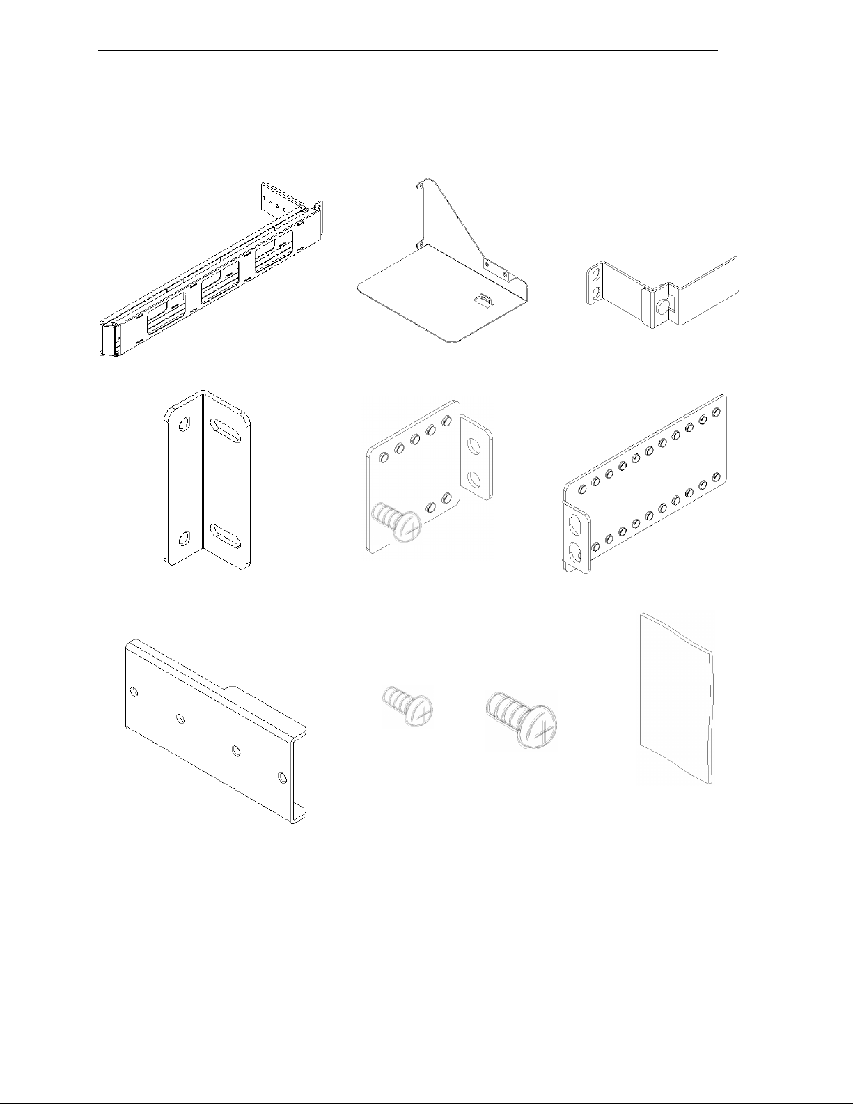
Unpacking
After unpacking the cable retention arm assembly, confirm that all parts shown below are included
in the kit.
Arm
Arm Bracket × Arm Stopper A
Arm Base
Arm Stopper Assembly
Arm Stopper B
Screw A
Arm EX
(No 6-32)
4 120Rd-2 Cable Arm Assembly Installation Notes
Screw B
User’s Guide
Page 5
Preparation
The following tool is required to install the cable retention arm assembly.
Small Philips driver
Installation
This document includes three cable retention arm assembly installation
procedures. They are Installation Procedure A, Installation Procedure B, and
Installation Procedure C. The procedure you use for installing the cable
retention arm assembly varies depending on the depth of the your system rack.
Also, some of the hardware used differs depending on the procedure you use.
Use the table below to determine the correct installation procedure you should
use.
Distance between the
mounting surface of
the front and rear
vertical rails
700mm ~ 774mm
(27.6in ~ 30.5in)
775mm ~ 829mm
(30.5in ~ 32.6in)
830mm ~ 900mm
(32.6in ~ 35.4in)
Installation procedure
you should use
Procedure A
Procedure B
Procedure C
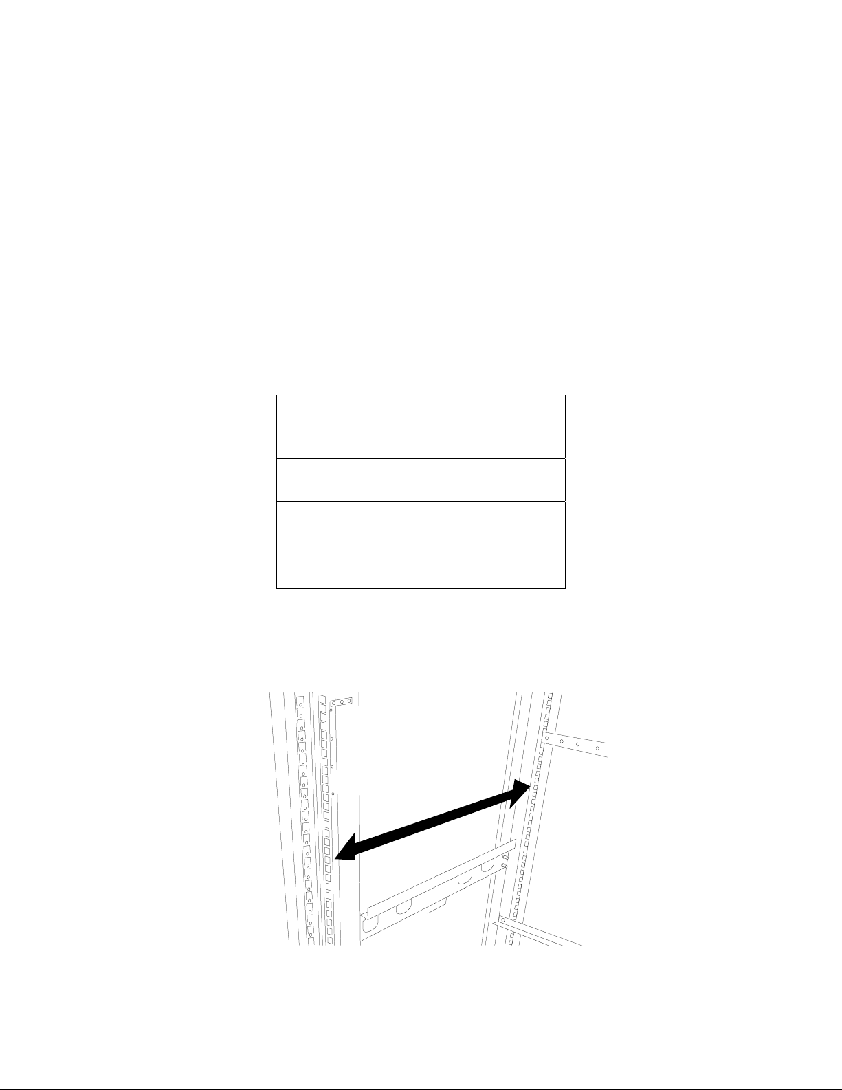
If you are unsure of the depth of your system rack, refer to the illustration below
and measure the distance between the inside surface of the front and rear
vertical mounting rails of your system rack.
120Rd-2 Cable Arm Assembly Installation Notes 5
Page 6
Installation Procedure A
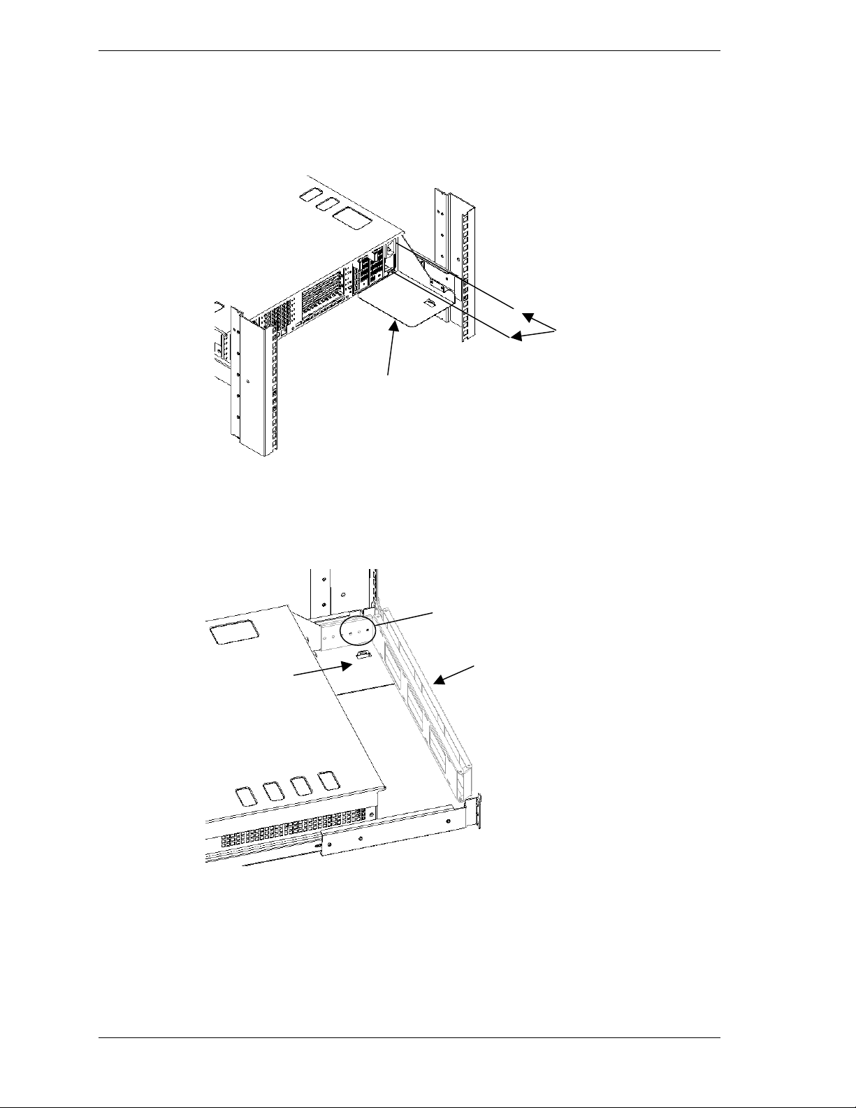
1. Attach the Arm Base to the rear of the power supply cage using the two
screws that secure the power supply cage to the chassis.
2. One end of the cable arm includes a long hinged bracket with six mounting
holes. The other end of the cable arm includes a small hinged bracket with
two mounting holes. Using two 6-32 screws attach the end of the cable arm
with the long hinged bracket to the arm base installed in the previous step.
Power Supply
Cage Screws (2)
Arm base
Arm base
Two 6-32
Cable arm
6 120Rd-2 Cable Arm Assembly Installation Notes
Page 7

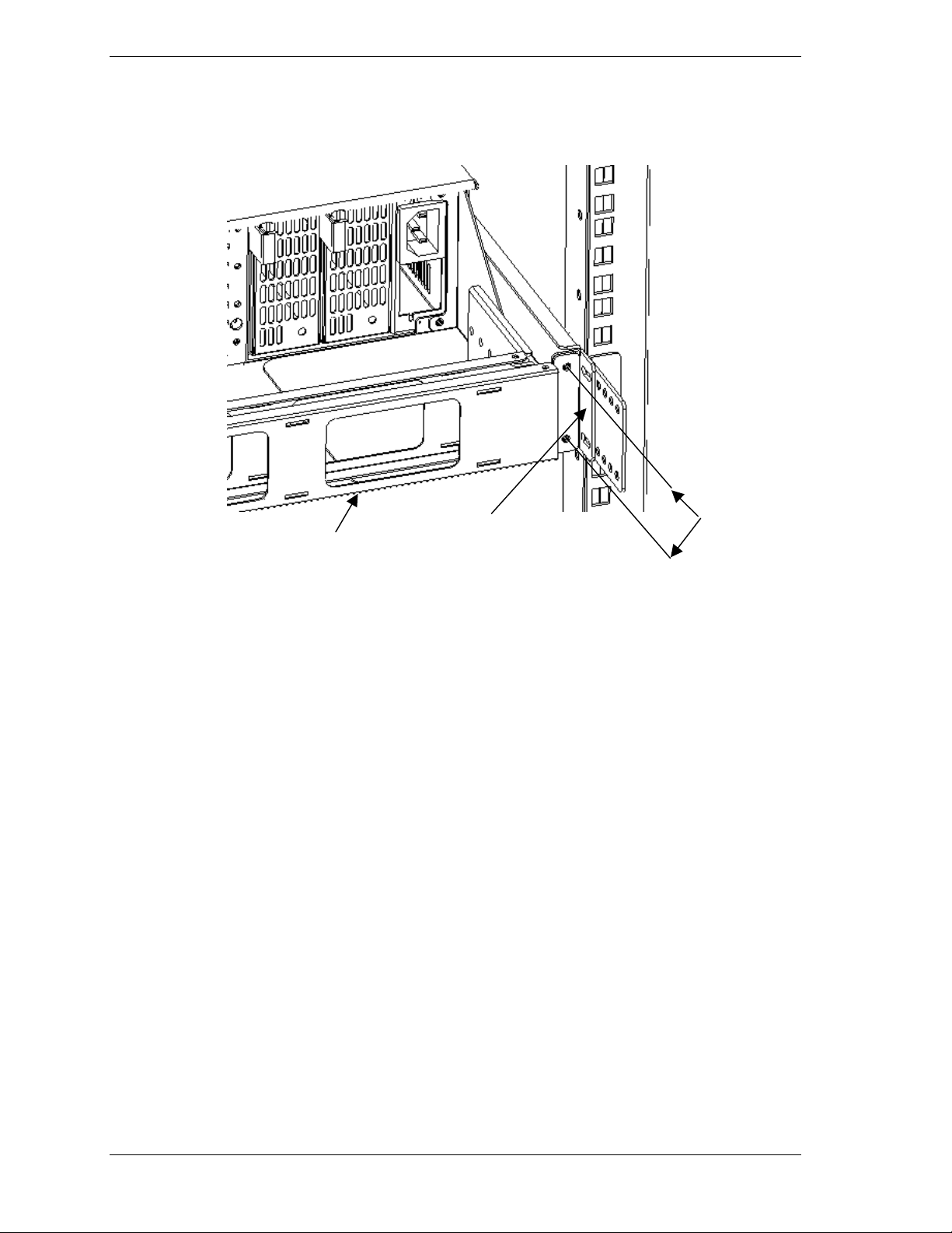
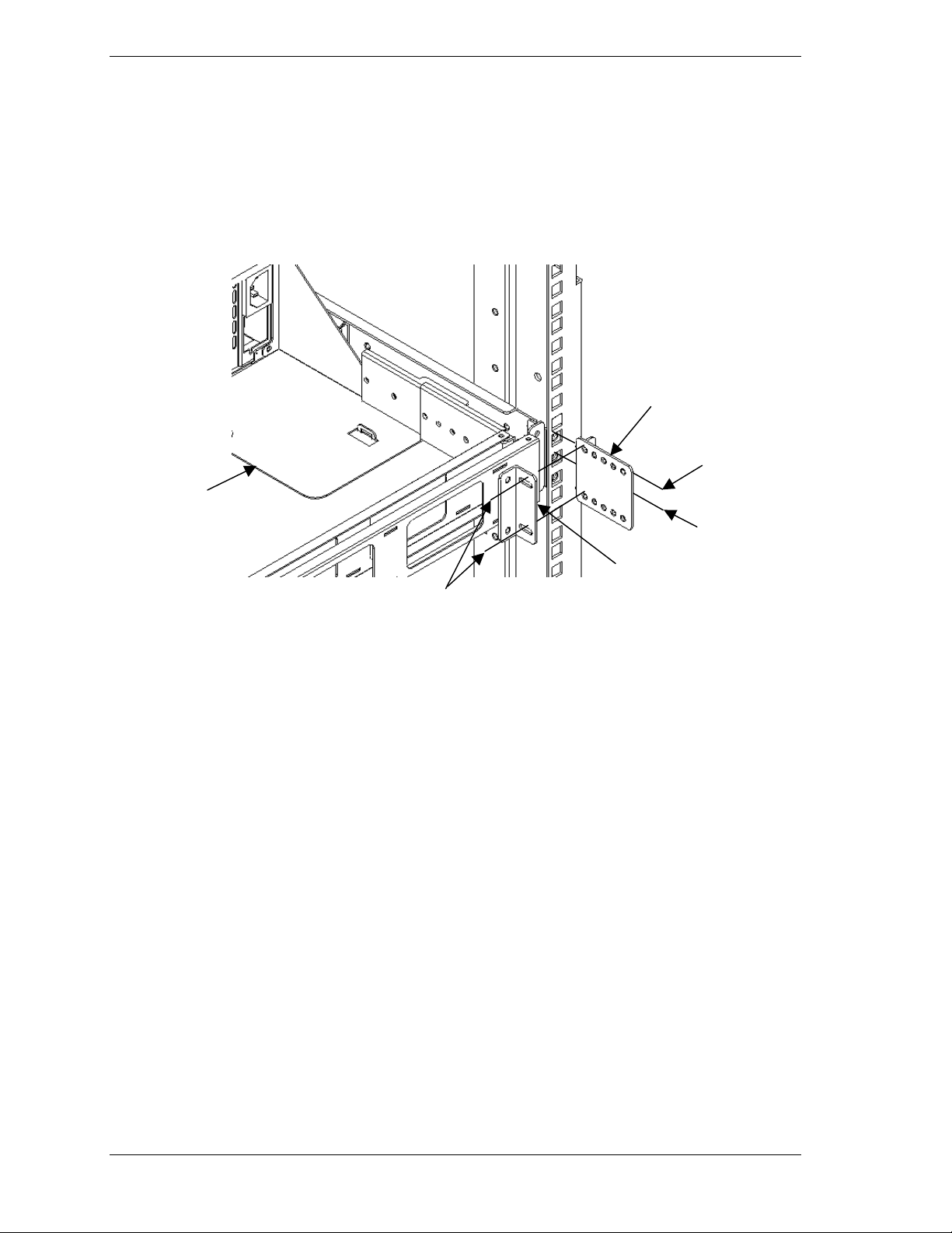
3. The arm bracket has four holes, two of which are elongated. Using the
elongated holes in the arm bracket, attach the arm bracket onto arm stopper
A using two 6-32 screws. Refer to the following illustration.
4. Using the upper rail bracket screw and one type B screw (see screw
illustrations on page 3), attach the Arm stopper A bracket to the rear cabinet
vertical rail.
Vertical rail
Arm stopper A
Two screw A
Use upper
vertical rail
bracket screw
Arm base
Use screw B. See
Two 6-32
screws
Page 3.
Arm bracket
120Rd-2 Cable Arm Assembly Installation Notes 7
Page 8
5. Install the free end of the cable arm to the arm bracket using two 6/32
screws.
Arm
Arm bracket
Two 6-32
8 120Rd-2 Cable Arm Assembly Installation Notes
Page 9

6. Press in on the rail release latches and slowly push the server in and out of
the system rack sev eral times. Ensure proper movement of the cable arm.
Adjustment of the cable arm hinged brackets may be necessary to attain
smooth operation. Tighten all screws. Ensure the server can be fully closed
and secured to the rack.
7. Bundle all the server cables together and tie-wrap them to the cable arm.
Cable arm
120Rd-2 Cable Arm Assembly Installation Notes 9
Page 10
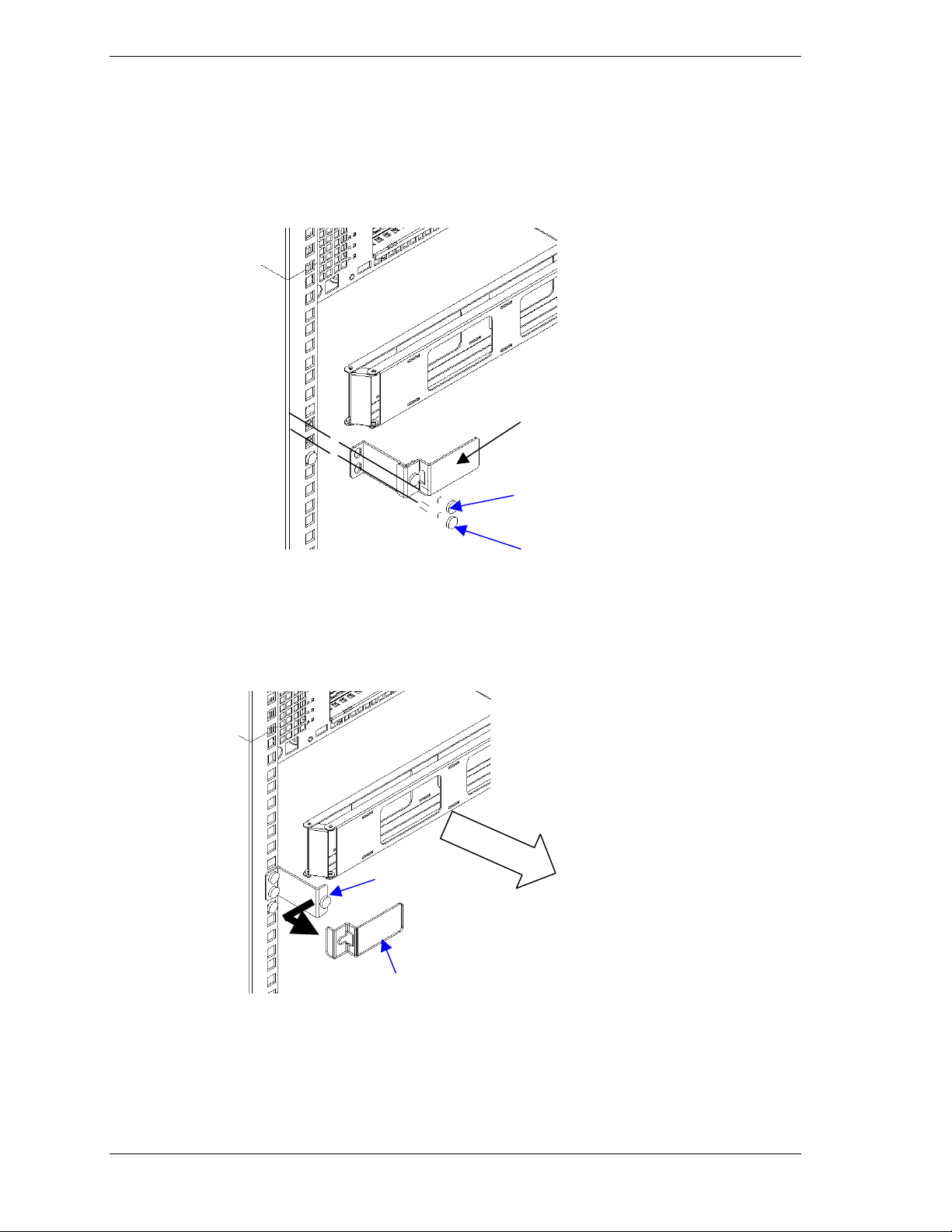
8. The Arm Stopper assembly keeps the cable arm from binding as the server is
pulled out of or pushed into the rack. Attach the Arm Stopper assembly to
the left rear vertical rail (viewed from t he rear of the cabinet) using one
Screw B and one screw rail bracket screw.
Arm stopper assembly
Rail bracket screw
(upper screw hole).
Screw B
9. When installing or removing cables, loosen the fixed screw and separate the
two pieces of the arm stopper assembly for easy access to the cable arm
assembly. See the figure below.
Fixed screw
Arm stopper
10 120Rd-2 Cable Arm Assembly Installation Notes
Page 11

Installation Procedure B
1. Attach the Arm Base to the rear of the power supply cage using the two
screws that secure the power supply cage to the chassis.
2. Position the Arm EX bracket as shown in the illustration below and using
two 6-32 screws attach the Arm EX bracket to the Arm Base.
Power Supply
Cage Screws (2)
Arm base
3. One end of the cable arm includes a long hinged bracket with six mounting
holes. The other end of the cable arm includes a small hinged bracket with
two mounting holes. Using two 6-32 screws attach the end of the cable arm
with the long hinged bracket to the Arm EX bracket.
Two 6-32
Arm EX
Arm base
Two 6-32
Cable
120Rd-2 Cable Arm Assembly Installation Notes 11
Page 12
4. The arm bracket has four holes, two of which are elongated. Using the
elongated holes in the arm bracket, attach the arm bracket onto arm stopper
A using two 6-32 screws. Refer to the following illustration.
5. Using the upper rail bracket screw and one type B screw (see screw
illustrations on page 3), attach the Arm stopper A bracket to the rear cabinet
vertical rail.
Arm stopper A
Arm base
Arm bracket
Two 6-32
Use upper
vertical rail
bracket screw
Use screw B. See
Page 3.
12 120Rd-2 Cable Arm Assembly Installation Notes
Page 13
6. Install the free end of the cable arm to the arm bracket using two 6/32
screws.
Two screw A
Arm
Arm bracket
120Rd-2 Cable Arm Assembly Installation Notes 13
Page 14

7. Press in on the rail release latches and slowly push the server in and out of
the system rack sev eral times. Ensure proper movement of the cable arm.
Adjustment of the cable arm hinged brackets may be necessary to attain
smooth operation. Tighten all screws. Ensure the server can be fully closed
and secured to the rack.
8. Bundle all the server cables together and tie-wrap them to the cable arm.
Cable
Arm
14 120Rd-2 Cable Arm Assembly Installation Notes
Page 15

Installation Procedure C
1. Attach the Arm Base to the rear of the power supply cage using the two
screws that secure the power supply cage to the chassis.
Power Supply
Cage Screws (2)
Arm base
2. Position the Arm EX bracket as shown in the illustration below and using
two 6-32 screws attach the Arm EX bracket to the Arm Base.
3. One end of the cable arm includes a long hinged bracket with six mounting
holes. The other end of the cable arm includes a small hinged bracket with
two mounting holes. Using two 6-32 screws attach the end of the cable arm
with the long hinged bracket to the Arm EX bracket.
Two 6-32
Arm EX
Arm base
Two 6-32
Cable
120Rd-2 Cable Arm Assembly Installation Notes 15
Page 16

4. The arm bracket has four holes, two of which are elongated. Using the
elongated holes in the arm bracket, attach the arm bracket onto arm stopper
B using two
6-32 screws. Refer to the following illustration.
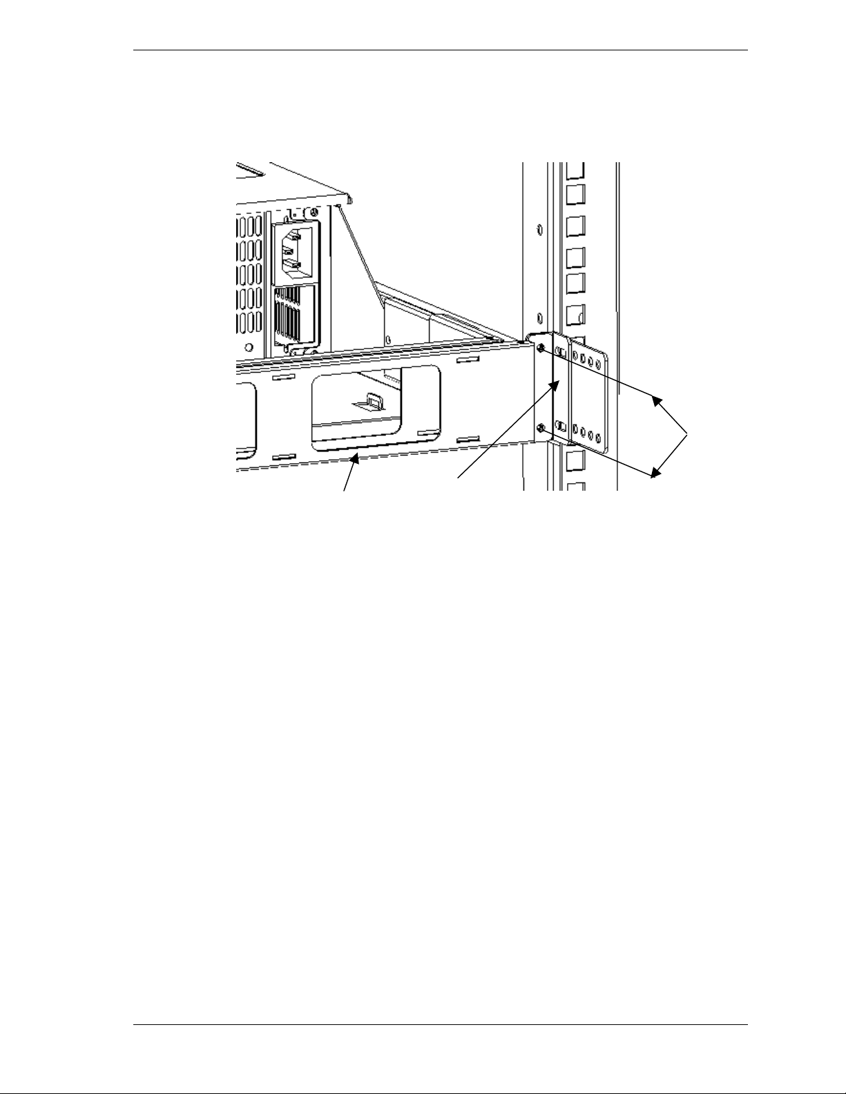
5. Using the upper rail bracket screw and one type B screw (see screw
illustrations on page 3), attach the Arm stopper B bracket to the rear cabinet
vertical rail.
Arm base
Arm stopper B
Use upper
vertical rail
bracket screw
Two 6-32
Use screw B. See
Page 3.
Arm bracket
16 120Rd-2 Cable Arm Assembly Installation Notes
Page 17

6. Install the free end of the cable arm to the arm bracket using two 6/32
screws.
Two screw A
Arm
Arm bracket
Two 6-32
screws
Arm bracket
7. Press in on the rail release latches and slowly push the server in and out of
the system rack sev eral times. Ensure proper movement of the cable arm.
Adjustment of the cable arm hinged brackets may be necessary to attain
smooth operation. Tighten all screws. Ensure the server can be fully closed
and secured to the rack.
8. Bundle all the server cables together and tie-wrap them to the cable arm.
Arm
120Rd-2 Cable Arm Assembly Installation Notes 17
Page 18

18 120Rd-2 Cable Arm Assembly Installation Notes
 Loading...