

Page 1

Installation Guide
Redundant Power Upgrade Kit
PN: 455-01593-000
Page 2

Proprietary Notice and Liability Disclaimer
The information disclosed in this document, including all designs and related materials, is
the valuable property of NEC Computers Inc. and/or its licensors. NEC Computers Inc.
and/or its licensors, as appropriate, reserve all patent, copyright and other proprietary rights
to this document, including all design, manufacturing, reproduction, use, and sales rights
thereto, except to the extent said rights are expressly granted to others.
The NEC Computers Inc. product(s) discussed in this document are warranted in
accordance with the terms of the Warranty Statement accompanying each product.
However, actual performance of each such product is dependent upon factors such as
system configuration, customer data, and operator control. Since implementation by
customers of each product may vary, the suitability of specific product configurations and
applications must be determined by the customer and is not warranted by NEC Computers
Inc.
To allow for design and specification improvements, the information in this document is
subject to change at any time, without notice. Reproduction of this document or portions
thereof without prior written approval of NEC Computers Inc. is prohibited.
Trademarks
All product, brand, or trade names used in this publication are the trademarks or registered
trademarks of their respective trademark owners.
First Issue — February 2000
Copyright 2000
NEC Computers Inc.
15 Business Park Way
Sacramento, CA 95828
All Rights Reserved
Page 3

Redundant Power Upgrade
Kit
Installation Procedures
This guide contains the information necessary to install, test, and troubleshoot
(if necessary) the Redundant Power Upgrade. This guide is written for
knowledgeable users, trained customer engineers, system analysts, service
center personnel, and dealers.
With the upgrade kit installed, the server will have power system redundancy
that allows the system to operate with a single power supply failure. Also, when
the additional redundant power supply is installed, both the standard and
additional redundant power supply slots become hot swappable.
Please read these installation procedures in their entirety before starting.
CONTENTS
Redundant Power Upgrade Kit Installation Procedures
Preparing the System ............................................................................................................................. 4
Removing the Server Side Panels...................................................................................................... 5
Removing the Standard Power Supply and Rear Mounting Plate ..................................................... 7
Removing the Power Supply Retaining Bracket ............................................................................... 8
Removing the Power Supply Blank Mounting Plate ......................................................................... 8
Installing the Upgrade Components..................................................................................................... 10
Installing the Power Controller Board............................................................................................. 11
Installing Jumpers and Disconnecting the Intrusion Switches......................................................... 13
Installing the LED/Switch Assembly............................................................................................... 14
Installing Interlock Switches ........................................................................................................... 16
Installing the Redundant Power Supplies........................................................................................ 17
Installing the Server Side Panels.......................................................................................................... 19
Powering Up and Testing the Server.................................................................................................... 19
Troubleshooting............................................................................................................................... 20
NEC
Page 4

NEC
Page 5
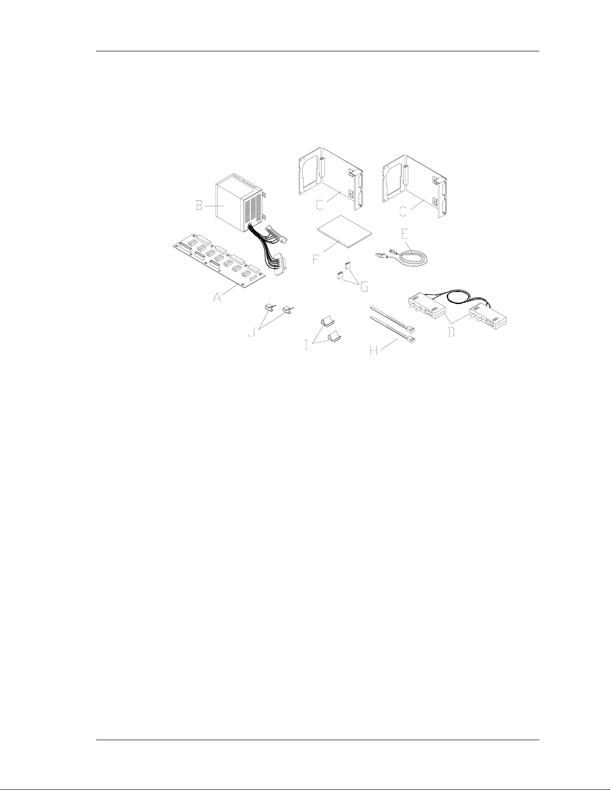
The NEC Redundant Power Upgrade Kit contains the components necessary for
adding system power redundancy capabilities to the NEC Express5800/120Mc2
and Express5800/120Mc3 Server Systems.
The following items shown in the figure below are included in the kit.
A
B
C
D
E
F
G
H
I
J
power controller board
redundant power supply (300 watts)
two power supply carriers
LED/switch assembly
ac power cord
this installation guide
two pin jumpers (2)
two tie-wraps
two cable keeps
two tie wrap clamps
Upgrade Kit Contents
Redundant Power Upgrade Kit Installation Procedures 3
Page 6

Use the following installation information as a guide for installing the upgrade
kit. Also, see the option installation instructions, which are located in the
"Upgrading Your System" Chapter of the User's Guide that come with the
online documentation on the NEC E
XPRESSBUILDER
CD-ROM supplied with the
server, or see the "Disassembly and Reassembly" Chapter of the Service Guide.
If additional option installation information is required, read and print it out
from the online document before beginning the upgrade installation.
The upgrade kit adds the following capabilities to the server:
redundant power
!
self-contained power supplies that can be easily installed or removed
!
from the rear of the chassis (hot swappable)
interlock switch capabilities
!
hardware monitors (power supply status and dc power status)
!
power presence switch.
!
The upgrade kit is installed in the following order:
prepare the system by removing the original components
!
install the new upgrade components
!
power up and test the installation
!
Preparing the System
Before installing the upgrade kit, the following components must be removed:
server side panels
!
standard power supply and mounting plate
!
power supply retaining bracket
!
power supply blank mounting plate.
!
Component removal is described in the following paragraphs.
4 Redundant Power Upgrade Kit Installation Procedures
Page 7

Removing the Server Side Panels
To install the redundant power upgrade in the server, the server side panels must
be removed. Also, please note that the right side panel removes in the same
manner as the left side panel.
!
CAUTION
For proper cooling and airflow, do not operate the system
with the side panels removed. Always replace the panels
before powering on the system.
!
WARNING
Before removing the server covers, turn off the power and
unplug the system power cables. Power is removed only
when the power cables are unplugged.
To remove a side panel:
1. Unlock and open the server front door (tower version only).
2. Close all programs in use and shutdown the operating system.
3. Turn off power to any peripheral devices.
4. Power off the server by pressing the power button on the front of the server.
The power indicator goes out.
5. Disconnect all cables from the back of the server and unplug all power
cords. The power supply status indicators go out.
6. The side panel is secured to the chassis with three thumbscrews (see figure
below). Loosen the thumb screws securing the side panel
7. Slide the side panel toward the rear of the chassis. This unlocks the locking
fingers behind the side panel.
8. Pull the side panel out and away from the chassis.
Redundant Power Upgrade Kit Installation Procedures 5
Page 8

Removing a Server Side Panel
6 Redundant Power Upgrade Kit Installation Procedures
Page 9

Removing the Standard Power Supply and Rear Mounting Plate
1. Power off the system and unplug the power supply ac power cable.
2. Remove the right side panel as described earlier.
3. Disconnect the internal power cables from the power supply inside the
chassis.
4. Remove the two screws securing the front of the power supply to the power
supply retaining bracket that is attached to the inside of the chassis.
5. Loosen the three thumbscrews (see A in figure below) that secure the power
supply assembly to the rear panel.
6. Remove the power supply assembly (B) from the rear of the chassis.
7. Remove the four screws (C) securing the power supply rear mounting plate
(D) and remove the plate.
Note:
The power supply's rear mounting plate is no
longer needed.
A
B
D
C
Removing the Power Supply and Rear Mounting Plate
Redundant Power Upgrade Kit Installation Procedures 7
Page 10

Removing the Power Supply Retaining Bracket
1. Power off the system and unplug the power supply ac power cable.
2. Remove the right side panel and standard power supply (if not already
removed) as described earlier.
3. Remove the screw (see figure below) that secures the power supply retaining
bracket to the chassis.
4. Remove the power supply retaining bracket from the chassis.
Note:
needed.
Removing the Power Supply Retaining Bracket
T
he power supply retaining bracket is no longer
Removing the Power Supply Blank Mounting Plate
1. Power off the system and unplug the power supply ac power cable.
2. Loosen the three thumbscrews (see A in figure below) that secure the power
supply blank mounting plate (B) to the rear panel.
3. Remove the power supply blank mounting plate (B) from the rear of the
chassis.
Note:
longer needed.
8 Redundant Power Upgrade Kit Installation Procedures
T
he power supply blank mounting plate is no
Page 11

Removing the Power Supply Blank Mounting Plate
Redundant Power Upgrade Kit Installation Procedures 9
Page 12

Installing the Upgrade Components
Install the following upgrade components:
power controller board
!
two jumpers
!
LED/switch assembly
!
interlock switches
!
two redundant power supplies.
!
See the following paragraphs for installation procedures.
10 Redundant Power Upgrade Kit Installation Procedures
Page 13

Installing the Power Controller Board
!
CAUTION
Electrostatic Discharge (ESD) can damage electronic
components.
Install the new power controller board in the server as follows.
1. Align the power controller board (A) so that its side power supply
connectors (J1, J3, J5, and J8) face the power supply slots (see the figure
below).
2. Install and secure the power controller board to the chassis with the ten
screws (B) and two tie wrap clamps (C) supplied with the kit. The two tie
wrap clamps are installed under the top two screws located on the left-hand
side of the power controller board.
Installing the Power Controller Board
Redundant Power Upgrade Kit Installation Procedures 11
Page 14

3. Attach the main power cable (A) that comes from the system board power
connector (see list below) to J9 on the power controller board (see the figure
below). Secure the cable by threading a tie wrap (B) through tie wrap clamp
(C) and around the cable, and tighten. Trim the plastic tie wrap.
For 120Mc2 System Board use the power cable from power connector P23.
For 120Mc3 System Board use the power cable from power connector P28.
4. Attach the back plane power cable (D) that comes from J4 on the SCSI
backplane to J6 on the power controller board (see the figure below). Secure
the cable by threading a tie wrap (E) through tie wrap clamp (F) and around
the cable, and tighten. Trim the plastic tie wrap.
Attaching the Power Controller Board Cables
12 Redundant Power Upgrade Kit Installation Procedures
Page 15

Installing Jumpers and Disconnecting the Intrusion Switches
To disconnect the intrusion switches and install the two new jumpers perform
the following procedures.
1. Remove the cable from connector J5 on the SCSI backplane (see the
following figure). The cable will be reconnected when installing the
Interlock Switches later in this Guide.
Unplugging the Intrusion Switches on the SCSI Backplane
2. Install the two jumpers supplied with your kit onto connector J5 on the SCSI
backplane (see the following figure).
Installing Jumpers on the SCSI Backplane
Redundant Power Upgrade Kit Installation Procedures 13
Page 16

Installing the LED/Switch Assembly
Install the new LED and presence switch assembly in the server as follows.
1. Insert the top and bottom power supply LED/switch assembly modules as
shown in the following figure. In the following two figures match A to
and B to B.
A
Installing the Top and Bottom LED/Switch Assembly Modules
2. Cable the top and bottom power supply LED/switch assembly modules
exactly as stated below and as shown in the following figure.
Top PSU LED Cable Connector (Single Cable) — Plugs into connector J7
on the power controller board.
Bottom PSU LED Cable Connector (Single Cable) — Plugs into connector
J2 on the power controller board.
Data Cable Connector (Double Cable) — Plugs into connector J7 on the
SCSI backplane. Remove the jumpers plugged into J7.
Secure the loose cables by attaching and using the two "Cable Keeps" (C),
as shown in the above figure. The "Cable Keeps" are attached by peeling the
backing off the adhesive and sticking them to the appropriate location on the
side of the chassis.
14 Redundant Power Upgrade Kit Installation Procedures
Page 17

Note:
When plugging in the Data cable connector (D)
and the Top and Bottom LED cable connectors (C and E),
pin 1 on these connectors must be positioned to line up with
pin 1 on the corresponding connectors they are plugging
into. For the location of pin 1 on these connectors, see the
following figure.
A
B
C
D
E
Bottom power supply LED/switch assembly module.
Top power supply LED/switch assembly module.
Top PSU LED cable connector.
Data cable connector.
Bottom PSU LED cable connector.
Attaching the LED/Switch Assembly Module Cables
Redundant Power Upgrade Kit Installation Procedures 15
Page 18

Installing Interlock Switches
To install interlock switches attach the cable connector previously removed
from J5 on the SCSI backplane to J13 on the power controller board (see the
following figure). Also, see step 1 in paragraph "Unplugging the Intrusion
Switches and Installing Jumpers" for cable connector previously removed from
J5 on the SCSI backplane.
Installing Interlock Switches Cable
16 Redundant Power Upgrade Kit Installation Procedures
Page 19

Installing the Redundant Power Supplies
Install the two redundant power supplies in the server as follows:
Perform the following procedures for each power supply.
1. Attach the two power supply cables to the connector bracket on the back of
the power supply carrier supplied with your kit (see the following figure).
Attaching the Two Power Supply Cables
2. Secure the power supply to the carrier with four screws on the rear carrier
plate and two screws on the front supporting brackets of the power supply
(see the following figure).
Attaching the Power Supply to the Carrier
3. Slide the power supply carrier into the power supply slot and secure with the
three thumbscrews.
Redundant Power Upgrade Kit Installation Procedures 17
Page 20

4. Ensure that both power supplies have their line voltage selector switch set to
the same voltage (see the following figure).
!
CAUTION
Before you plug the system power cord into an AC outlet,
ensure the input line voltage setting for the power supply is
correct.
To use the system with line source voltages between 200
and 240 VAC, the line voltage selector switch on the power
supply must be set to 230. If you set the switch to the 115
VAC position, the power supply will be damaged when you
plug in your system.
When two power supplies are installed in the system both
power supplies must have their line voltage selector switch
set to the same voltage.
If you need to change the line voltage setting, perform the following steps.
1. Unplug the AC power cord from the back of the chassis.
2. Insert the tip of a small screwdriver or ballpoint pen into the depression on
the line voltage selector.
3. Slide the selector switch to 115 VAC or to 230 VAC (line source voltage
range: 220 to 240 VAC).
A
– Voltage selector switch set to 115 VAC
B
–
Voltage selector switch set to 230 VAC
Setting the Line Voltage
18 Redundant Power Upgrade Kit Installation Procedures
Page 21

Installing the Server Side Panels
Use this procedure to install the two side panels on your server. (See "Removing
the Server Side Panels" earlier in this document for additional information.)
Install the side panels as follows.
1. From the rear of the server align the locking tabs on each side panel with the
corresponding slots in the chassis.
2. Slide each side panel towards the front of the chassis until it locks in place.
3. Secure each side panel with its thumbscrews.
Powering Up and Testing the Server
Installation of the Upgrade Kit is now complete; power up and test the server.
Connect all cables and ac power cords as follows.
Note:
1. As appropriate, connect all cables previously removed from the back of the
server.
2. Connect an ac power cord from each of the power supplies to an ac power
outlet (see the following figure).
Make sure all cable connections are tight.
Plugging in the AC Power Cords
Redundant Power Upgrade Kit Installation Procedures 19
Page 22

Power up and test the server as follows.
1. Press the Power button on the front panel.
2. The server boots up.
3. Check the front system indicators for power alarms and abnormal power
status.
4. If no messages appear on the monitor screen, turn off the server and see
"Troubleshooting,"next.
Troubleshooting
After installation of the upgrade kit, during the server's initial power up
sequence, if no messages appear on the monitor screen, check the following.
Are all peripheral and power cables securely connected? Check and
!
tighten the cables.
Are both power supplies fully seated and installed correctly? Check
!
installation and reseat the power supplies.
Is the monitor powered on and adjusted correctly? Turn monitor power
!
on and adjust the controls.
Does the electrical outlet have ac power? Check the outlets.
!
Are the side panels properly installed? Remove and reinstall.
!
If this does not solve the problem, power down the server and
!
peripherals, disconnect all peripherals, unplug the power cords, and
open the server to check for:
internal cabling pinched or improperly connected
incorrect jumper setting on the SCSI backplane
improperly installed power controller board.
If the problem persists, contact your NEC service representative.
!
20 Redundant Power Upgrade Kit Installation Procedures
 Loading...