

Page 1

E
()
■■■■■■■
■■■■■■■
■■■■■■■
■■■■■■■
■■■■■■■
■■■■■■■
XPRESS
5800/120Ee
User’s Guide
■■■■■■■
■■■■■■■
■■■■■■■
■■■■■■■
■■■■■■■
■■■■■■■
■■■■■■■
■■■■■■■
Page 2

xxx
Page 3

E
XPRESS
()
■■■■■■■
■■■■■■■
■■■■■■■
■■■■■■■
■■■■■■■
■■■■■■■
5800/120Ee
User’s Guide
■■■■■■■
■■■■■■■
■■■■■■■
■■■■■■■
■■■■■■■
■■■■■■■
■■■■■■■
■■■■■■■
Page 4

Proprietary Notice and Liability Disclaimer
The information disclosed in this document, including all designs and related materials, is
the valuable property of NEC Solutions (America), Inc. and/or its licensors. NEC Solutions
(America), Inc. and/or its licensors, as appropriate, reserve all patent, copyright and other
proprietary rights to this document, including all design, manufacturing, reproduction, use,
and sales rights thereto, except to the extent said rights are expressly granted to others.
The NEC Solutions (America), Inc. product(s) discussed in this document are warranted in
accordance with the terms of the Warranty Statement accompanying each product.
However, actual performance of each product is dependent upon factors such as system
configuration, customer data, and operator control. Since implementation by customers of
each product may vary, the suitability of specific product configurations and applications
must be determined by the customer and is not warranted by NEC Solutions (America), Inc.
To allow for design and specification improvements, the information in this document is
subject to change at any time, without notice. Reproduction of this document or portions
thereof without prior written approval of NEC Solutions (America), Inc. is prohibited.
Trademarks
Windows NT is a trademark of Microsoft Corporation.
Windows 2000 is a registered trademark of Microsoft Corporation.
Pentium III is a registered trademark of Intel Corporation.
All other product, brand, or trade names used in this publication are the trademarks or registered
trademarks of their respective trademark owners.
PN: 456-01586-N00
Copyright 2002
NEC Solutions (America), Inc
15 Business Park Way
Sacramento, CA 95828
All Rights Reserved
Page 5

Contents
Proprietary Notice
Using This Guide
Text Conventions...............................................................................................................viii
Related Documents .............................................................................................................. ix
Safety Notices....................................................................................................................... x
Safety Notices for Users Outside of the U.S.A. and Canada.......................................... xi
Care and Handling...............................................................................................................xii
1 System Overview
Overview............................................................................................................................ 1-2
System Chassis................................................................................................................... 1-4
Power Supply.....................................................................................................................1-5
Peripheral Bays..................................................................................................................1-5
System Board Features.......................................................................................................1-6
Pentium III Processor.................................................................................................... 1-7
System Memory............................................................................................................1-7
Real-Time Clock/Calendar ...........................................................................................1-7
BIOS .............................................................................................................................1-7
I/O Expansion Slots ......................................................................................................1-8
IDE Controller .............................................................................................................. 1-9
Keyboard and Mouse Controller...................................................................................1-9
Network Controller.......................................................................................................1-9
Video Controller ...........................................................................................................1-9
Peripheral Controller...................................................................................................1-10
Serial Ports..........................................................................................................1-10
Parallel Port......................................................................................................... 1-10
External Device Connectors........................................................................................1-10
ACPI ...........................................................................................................................1-10
AC Link Mode .................................................................................................................1-11
Remote Power-On (Wake ON LAN) Function................................................................ 1-12
Degradation Feature.........................................................................................................1-12
System Security................................................................................................................1-12
Security with Mechanical Locks and Monitoring....................................................... 1-12
Software Locks via the System Setup Utility .............................................................1-12
2 Setting Up the System
Overview............................................................................................................................ 2-2
Selecting a Site...................................................................................................................2-2
Unpacking the System........................................................................................................2-3
Getting Familiar with the System.......................................................................................2-4
Front View....................................................................................................................2-4
Rear View ..................................................................................................................... 2-5
Making Connections ..........................................................................................................2-6
Connecting the Power Cord...............................................................................................2-7
Powering On Your System.................................................................................................2-8
Contents iii
Page 6

3 Configuring Your System
Configuring Your System...................................................................................................3-2
BIOS Setup Utility..............................................................................................................3-3
Using the BIOS Setup Utility........................................................................................3-3
BIOS Setup Configuration Settings...............................................................................3-4
Main Menu....................................................................................................................3-5
Advanced Menu ............................................................................................................3-6
Advanced Submenu...............................................................................................3-6
Memory Reconfiguration Submenu ......................................................................3-6
CPU Reconfiguration Submenu............................................................................3-7
Peripheral Configuration Submenu.......................................................................3-7
Peripheral Configuration Submenu (Continued)...................................................3-7
PCI Device Submenu.............................................................................................3-9
Option ROM Submenu..........................................................................................3-9
Numlock Submenu..............................................................................................3-10
Security Menu.............................................................................................................3-11
Secure Mode................................................................................................................3-12
System Hardware Menu..............................................................................................3-12
Thermal Sensor Submenu....................................................................................3-13
Wake On Events Submenu..................................................................................3-13
Console Redirection Submenu............................................................................3-13
Boot Menu...................................................................................................................3-14
Boot Device Priority Menu..................................................................................3-14
Exit Menu....................................................................................................................3-15
Exit Menu............................................................................................................3-15
Configuring System Board Jumpers.................................................................................3-16
Before You Begin........................................................................................................3-16
Moving System Board Jumpers ..................................................................................3-17
Clearing and Changing the Passwords........................................................................3-18
Clearing CMOS...........................................................................................................3-19
4 Upgrading Your System
General Information ...........................................................................................................4-2
Static Precautions ...............................................................................................................4-2
Preparing Your System for Upgrade ..................................................................................4-3
Equipment Log...................................................................................................................4-3
Removing the Side Panels..................................................................................................4-3
Installing Side Panels..........................................................................................................4-4
Modifying the System Board..............................................................................................4-5
Replacing the Real-time Clock Battery.........................................................................4-5
Removing and Installing a Pentium III Processor.........................................................4-7
DIMMs........................................................................................................................4-12
Option Boards...................................................................................................................4-15
Installing a PCI Option Board.....................................................................................4-16
Removing an Option Board.........................................................................................4-17
Cable Protector.................................................................................................................4-18
Installing the Cable Protector......................................................................................4-18
Hard Disk Drives..............................................................................................................4-19
Installing an Internal Hard Disk Drive........................................................................4-19
Removing an Internal Hard Disk Drive.......................................................................4-25
Front Panel........................................................................................................................4-26
Removing the Front Panel...........................................................................................4-26
Installing the Front Panel ............................................................................................4-27
iv Contents
Page 7

Removing EMI Shields and Filler Panels........................................................................4-28
Removable Media Devices...............................................................................................4-29
Installing a 5.25-Inch Device...................................................................................... 4-29
Removing a 5.25-Inch Device ....................................................................................4-31
5 Problem Solving
Problem Solving.................................................................................................................5-2
Static Precautions...............................................................................................................5-2
Troubleshooting Checklists................................................................................................5-3
Initial System Startup....................................................................................................5-3
Running New Application Software.............................................................................5-4
After System Has Been Running Correctly..................................................................5-5
Diagnostic Testing..............................................................................................................5-6
Error Checking.............................................................................................................. 5-6
Troubleshooting Guide .................................................................................................5-6
Preparing the System for Diagnostic Testing........................................................5-6
Monitoring POST.................................................................................................. 5-7
Verifying Proper Operation of Key System Indicators.........................................5-8
Confirming Loading of the Operating System......................................................5-8
Specific Problems and Corrective Actions.........................................................................5-9
Power LED Does Not Light.......................................................................................... 5-9
Incorrect or No Beep Code.........................................................................................5-10
No Characters Appear on Screen................................................................................5-10
Characters are Distorted or Incorrect.......................................................................... 5-11
System Cooling Fans Do Not Rotate..........................................................................5-11
Diskette Drive Activity LED Does Not Light.............................................................5-11
CD-ROM Drive Activity Light Does Not Light.........................................................5-11
Problems with Application Software..........................................................................5-12
Bootable CD-ROM Is Not Detected........................................................................... 5-12
Problems with the Network..............................................................................................5-12
Plug and Play Installation Tips.........................................................................................5-13
BIOS User’s Information................................................................................................. 5-13
POST Error Codes and Messages............................................................................... 5-14
How to Identify BIOS Revision Level............................................................................. 5-17
BIOS Revision Level Identification............................................................................ 5-17
A System Cabling
System Cabling................................................................................................................. A-2
Before You Begin ............................................................................................................. A-2
Static Precautions..............................................................................................................A-2
Standard Configuration..................................................................................................... A-3
B Specifications
System Specifications....................................................................................................... B-2
Contents v
Page 8

C Installing and Configuring Windows 2000 and Windows NT 4.0
Windows 2000.................................................................................................................. C-2
Device Drivers..............................................................................................................C-2
Installation Assumption................................................................................................C-3
Preparation ................................................................................................................... C-4
Installing Microsoft Windows
®
2000 Operating System.............................................C-5
Installing LAN Adapters..............................................................................................C-6
Driver Installation for the Intel PRO/100+ LAN Adapter....................................C-6
Driver Installation for the ATI RAGE XL Display Adapter........................................C-6
Windows NT 4.0................................................................................................................C-7
Device Drivers..............................................................................................................C-7
Configuring RAID .......................................................................................................C-8
Installing Microsoft Windows
®
NT 4.0 Operating System.......................................... C-8
Installing LAN Adapter Drivers..................................................................................C-9
Driver Installation for the Intel PRO/100+ LAN Adapter....................................C-9
Driver Installation for the ATI RAGE XL Display Adapter...........................................C-10
Glossary
Equipment Log
INDEX
vi Contents
Page 9

Using This Guide
The E
XPRESS
5800/120Ee User’s Guide provides a quick reference to information about
your system. Its goal is to familiarize you with your system and the tasks necessary for
system configuring and upgrading.
This guide contains the following information:
Chapter 1, “System Overview” provides an overview of your system and describes your
!
system’s major system components. See this chapter to familiarize yourself with your
system.
Chapter 2, “Setting Up Your System” tells you how to select a site, unpack the system,
!
make cable connections, and power on your system.
Chapter 3, “Configuring Your System” tells you how to configure the system and
!
provides instructions for running the BIOS Setup Utility. This chapter also provides
information on system board jumper settings.
Chapter 4, “Upgrades and Options” provides you with instructions for upgrading your
!
system with an additional processor, optional memory, options cards, and peripheral
devices.
Chapter 5, “Problem Solving” contains helpful information for solving problems that
!
might occur with your system.
Appendix A, “System Cabling” includes cabling information for the two-channel IDE
!
controller and the onboard IDE diskette controller.
Appendix B, “Specifications” includes hardware information about your server.
!
Appendix C, “Installing and Configuring Windows 2000® and Windows NT 4.0®”
!
contains instructions to manually install and configure hardware and software used with
the Microsoft Windows 2000 Operating System and Microsoft Windows NT Operating
System.
“Glossary” defines the standard acronyms and technical terms used in this manual.
!
“Equipment Log” provides you with a sample equipment log for documenting the
!
system configuration and future updates you may make to your system.
Using This Guide vii
Page 10
Text Conventions
This guide uses the following text conventions.
Warnings, cautions, and notes have the following meanings:
Warnings alert you to situations that could result in serious personal injury or loss
of life.
Cautions indicate situations that can damage the system hardware or software.
!
WARNING
!
CAUTION
Note:
Names of keyboard keys are printed as they appear on the keyboard. For example, Ctrl,
!
Alt, or Enter.
Text or keystrokes that you enter appear as boldface type. For example, type abc123 and
!
press ENTER.
File names are printed in uppercase letters. For example, AUTOEXEC.BAT.
!
Notes give important information about the material being described.
viii Using This Guide
Page 11

Related Documents
In addition to this guide, the following system documentation is included with your server
either as electronic files on E
System Release Notes
!
Release Notes provide you with the latest information about your system. This
information was not available to be included in your user's guide at the time it was
developed and released.
Getting Started Sheet
!
The Getting Started Sheet provides several easy-to-follow steps to become familiar with
your server documentation and to complete your installation successfully.
XPRESSBUILDER
or as paper copy shipped with your server.
Using This Guide ix
Page 12

Safety Notices
Caution: To reduce the risk of electric shock which could cause personal injury, follow
!
all safety notices. The symbols shown are used in your documentation and on your
equipment to indicate safety hazards.
Warning: Lithium batteries can be dangerous. Improper handling of lithium batteries
!
may result in an explosion. Dispose of lithium batteries as required by local ordinance or
as normal waste if no local ordinance exists.
Warning: The detachable power supply cord is intended to serve as the disconnect
!
device.
Warning: This equipment has a 3-wire, grounded power cord. To prevent electrical
!
hazards, do not remove or defeat the ground prong on the power cord. Replace the
power cord if it gets damaged. Contact your dealer for an exact replacement.
Warning: The DC push-button on/off switch on the front panel does not turn off the
!
system AC power. Also, +5vdc is present on the system board whenever the AC power
cord is connected between the system and an AC outlet. Before doing the procedures in
this manual, make sure that your system is powered off and unplug the AC power cord
from the back of the chassis. Failure to disconnect power before opening your system
can result in personal injury and equipment damage.
!
In the U.S.A. and Canada, the power cord must be a UL-listed detachable power cord (in
Canada, CSA-certified), type ST or SJT, 16 AWG, 3-conductor, provided with a molded-on
NEMA type 5-15 P plug cap at one end and a molded-on cord connector body at the other
end. The cord length must not exceed 9 feet (2.7 meters).
Outside the U.S.A. and Canada, the plug must be rated for 250 VAC, 10 amp minimum,
and must display an international agency approval marking. The cord must be suitable for
use in the end-user country. Consult your dealer or the local electrical authorities if you are
unsure of the type of power cord to use in your country. The voltage change occurs via a
switch in the power supply.
Warning: Under no circumstances should the user attempt to disassemble the power
!
supply. The power supply has no user-replaceable parts. Inside the power supply are
hazardous voltages that can cause serious personal injury. A defective power supply
must be returned to your dealer.
x Using This Guide
Page 13

Safety Notices for Users Outside of the U.S.A. and Canada
PELV (Protected Extra-Low Voltage) Integrity: To ensure the extra-low voltage
!
integrity of the equipment, connect only equipment with mains-protected electricallycompatible circuits to the external ports.
Remote Earths: To prevent electrical shock, connect all local (individual office)
!
computers and computer support equipment to the same electrical circuit of the building
wiring. If you are unsure, check the building wiring to avoid remote earth conditions.
Earth Bonding: For safe operation, only connect the equipment to a building supply
!
that is in accordance with current wiring regulations in your country. In the U.K., those
regulations are the IEE.
Using This Guide xi
Page 14
Care and Handling
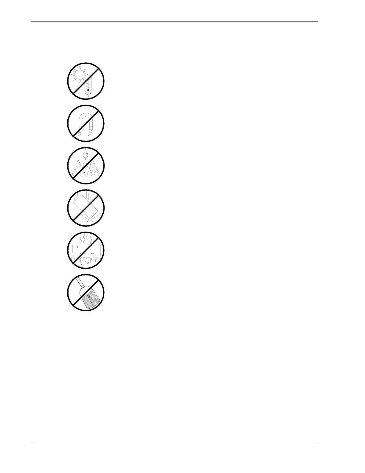
Use the following guidelines to properly handle and care for your system.
Protect the system from extremely low or high temperatures. Let
the system warm (or cool) to room temperature before using it.
Keep the system away from magnetic forces.
Keep the system dry. Do not wash the system with a wet cloth or
pour fluid into it.
Protect the system from being bumped or dropped.
Check the system for condensation. If condensation exists, allow it
to evaporate before powering on the system.
Keep the system away from dust, sand, and dirt.
xii Using This Guide
Page 15

System Overview
!
Overview
!
System Chassis
!
Power Supply
!
Peripheral Bays
!
System Board Features
!
AC Link Mode
!
Remote Power-On (Wake ON LAN) Function
!
Degradation Feature
1
!
System Security
Page 16
Overview
Your server is a modular, multiprocessing server based on the Intel Pentium® III
microprocessor family. It is a solid performer and offers the latest technology. The
combination of compute performance, memory capacity, and integrated I/O provides a
high performance environment for many server market applications. These range from
large corporations supporting remote offices to small companies looking to obtain basic
connectivity capability such as file and print services, e -mail, web access, web site
server, etc.
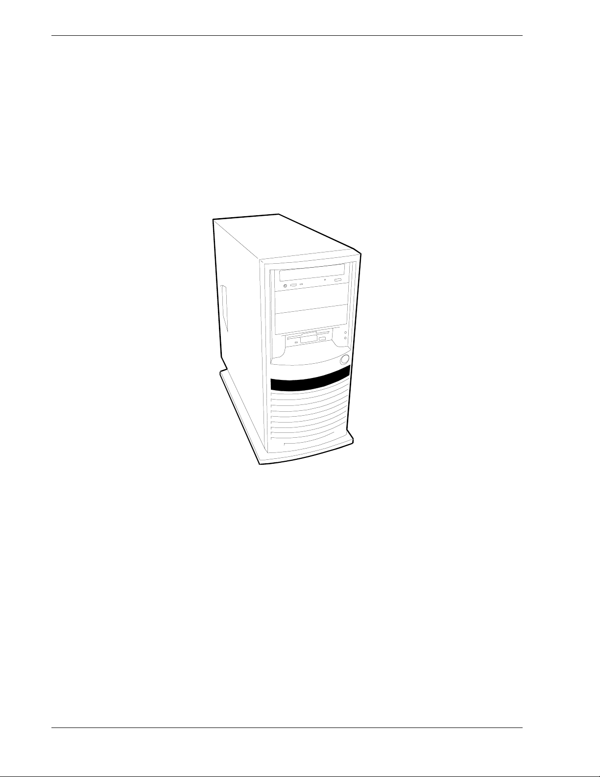
This server is conveniently housed as a tower-based as shown in Figures 1-1.
Exceptional standard features included with your server ensure high performance and
high reliability.
Single and dual-performance Intel Pentium III Proc e s sors
!
128 MB to 4 GB of memory, using up to four DIMMs.
!
High-speed 100BASE-TX/10BASE-T interface (100Mbps/10Mbps supported)
!
High-speed disk access (Ultra ATA100)
!
Memory monitoring feature (1-bit error correction/ 2-bit error detection)
!
CPU/memory/cooling fan degradation feature (logical isolation of a failed
!
device)
Hardware monitors (temperature, fans, and voltage) and software monitors to
!
indicate failures
1-2 System Overview
Figure 1-1. Front View
Page 17

Error notification
!
BIOS password feature
!
Security feature (security lock).
!
As application requirements increase, you can expand your server with an additional
processor, additional memory, add-in boards and peripheral devices: tape devices,
CD-ROM, diskette drives and hard disk drives. Also included with your system is:
Six PCI expansion slots for add-in boards including four 33MHz PCI bus slots
!
and two 66MHz PCI bus slots
Embedded PC-compatible support (serial, parallel, mouse, keyboard, diskette,
!
USB, LAN, and video)
ATI RAGE XL (VRAM) integrated onboard video controller with 8 MB of
!
video memory
Dual Channel enhanced IDE controller
!
Three 5 ¼-inch removable media expansion bays with a 48-speed CD-ROM
!
drive installed in one bay
One 3 ½-inch half-height bay with a diskette drive installed
!
Integrated dual Universal Serial Bus (USB) ports
!
One standard auto-sensing 264 watt power supply
!
Hard disk expansion bays supporting two IDE hard disk drives.
!
System Overview 1-3
Page 18
System Chassis
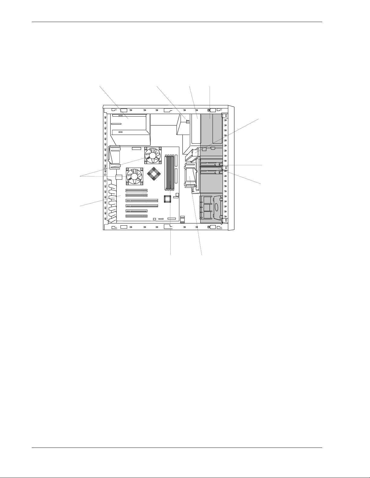
The system chassis (Figure 1-2) is an easy-to-expand, fabricated metal structure. The
major system components are shown in the following illustration.
ABCD
K
J
E
F
G
A. System power supply
B. CD-ROM drive
C. 5 ¼-inch device bay
D. Cable protector (shaded area)
E. 3.5-inch floppy disk drive
F. Hard Disk Drive Bay
G. Hard disk drive (option)
H. Cooling fan
I. DIMM
J. System board
K. CPU (CPU 2 is optional)
Figure 1-2. System Chassis
HI
1-4 System Overview
Page 19

Power Supply
The 264-watt auto-voltage-sensing power supply provides system power. The power
supply operates at 115 or 230 VAC at an operating frequency of 50/60 Hz. It is
designed to comply with existing emission standards and provides sufficient power for
a fully loaded system configuration.
Peripheral Bays
The system supports a variety of standard PC AT-compatible peripheral devices. The
chassis includes these peripheral bays:
A 3.5-inch front panel bay for mounting the standard 3.5" diskette drive
!
(supports 720 KB and 1.44 MB diskette media)
Three 5.25-inch removable media front panel bays for mounting half-height
!
5.25-inch peripheral devices: standard CD-ROM drive and optional tape drives,
etc.
A 3.5-inch hard disk drive bay for installing up to two hard disk drives.
!
System Overview 1-5
Page 20
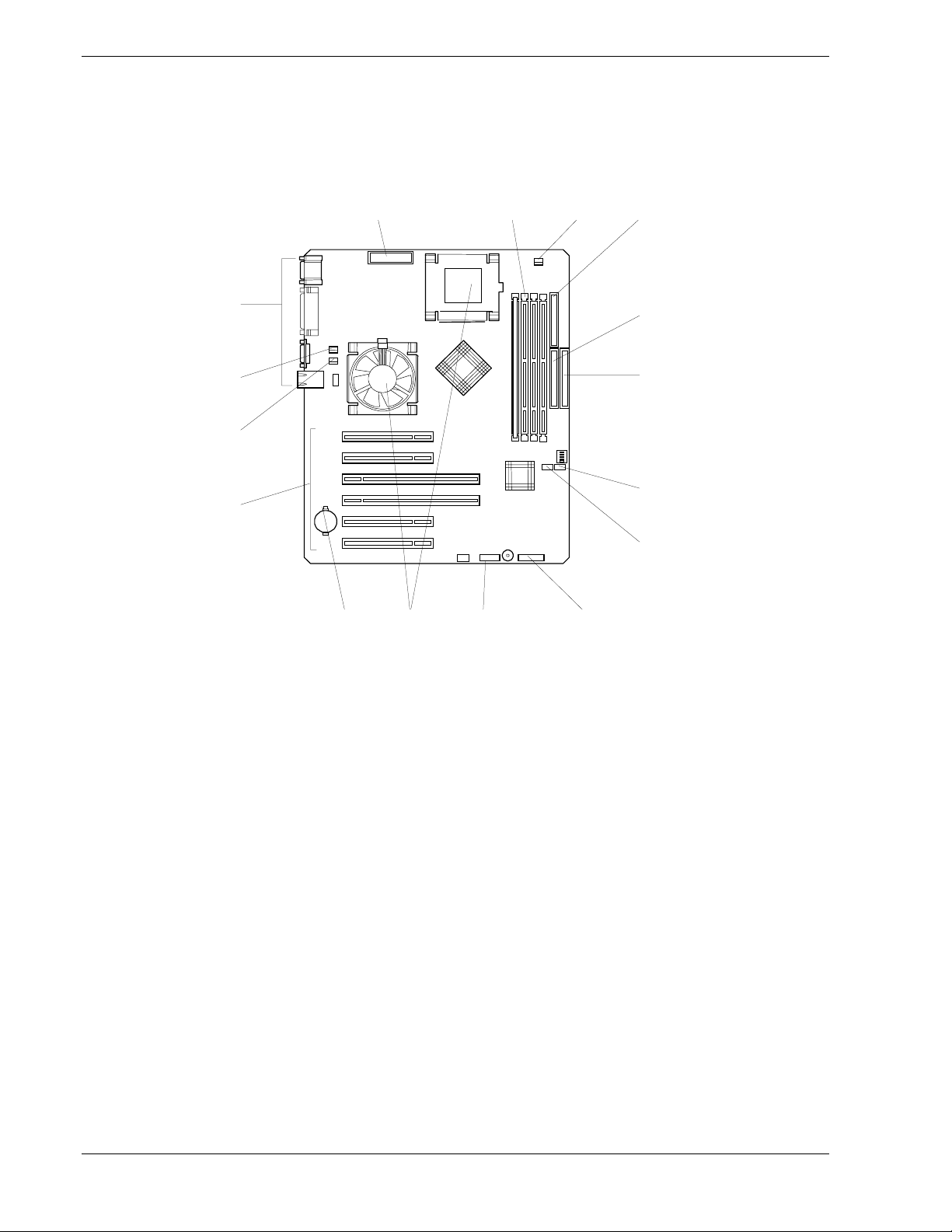
System Board Features
The system board (Figure 1-3) offers a “flat” design with the processor and memory
subsystems residing on the board. This figure shows the major components on the
system board. The following subsections describe the system board major components.
ABCD
P
O
E
F
N
G
M
H
IJKL
A. Power supply connector I. Front panel connector
B. DIMM sockets (Slot #1, Slot #2, Slot #3,
and Slot #4 from left)
C. CPU #2 cooling fan connector K. CPU connectors (left: CPU1 (standard), right:
J. CMOS/password clear jumper switch
CPU2 (optional))
D. Floppy disk drive connector L. Lithium battery
E. IDE connector (for the CD-ROM drive) M. PCI board slots (6 slots: PCI#1, PCI#2, PCI#3,
PCI#4, PCI#5, and PCI#6 from top)
F. IDE connector (for the internal hard disk) N. Rear cooling fan connector
G. Cooling fan connector (internal hard disk) O. CPU #1 cooling fan connector
H. Cooling fan connector (PCI device) P.
Connector for external connections (See the
previous page.)
Figure 1-3. System Board
1-6 System Overview
Page 21

Pentium III Processor
Depending on system configuration, your server includes one or two Pentium III
processors. Each Pentium III plugs into a ZIF (Zero Insertion Force) socket on the
system board. The processor includes a numeric coprocessor, a 256KB L2 cache and
operates at a bus speed of 133MHz. The optional second Pentium III processor
enhances performance and enables symmetric multiprocessing (SMP).
System Memory
The system board contains four 168-pin DIMM sockets. Memory is partitioned as four
banks of SDRAM registered DIMMs (PC133 compatible), each providing 72 bits of
noninterleaved memory (64-bit main memory plus ECC). Your system may include
from 128MB to 4GB of memory, using up to four DIMMs.
System memory begins at address 0 and is continuous (flat addressing) up to the
maximum amount of DRAM installed (exception: system memory is noncontiguous in
the ranges defined as memory holes using configuration registers). The system
supports both base (conventional) and extended memory.
Real-Time Clock/Cale ndar
The real-time clock provides system clock/calendar information stored in a non-volatile
memory (NVRAM). The real-time clock battery provides power backup for the realtime clock.
BIOS
A BIOS and Setup Utility are located in the Flash EPROM on the system board and
include support for system setup and Legacy device configuration. A number of
security, reliability, and management features also have been incorporated to meet vital
server needs.
System Overview 1-7
Page 22
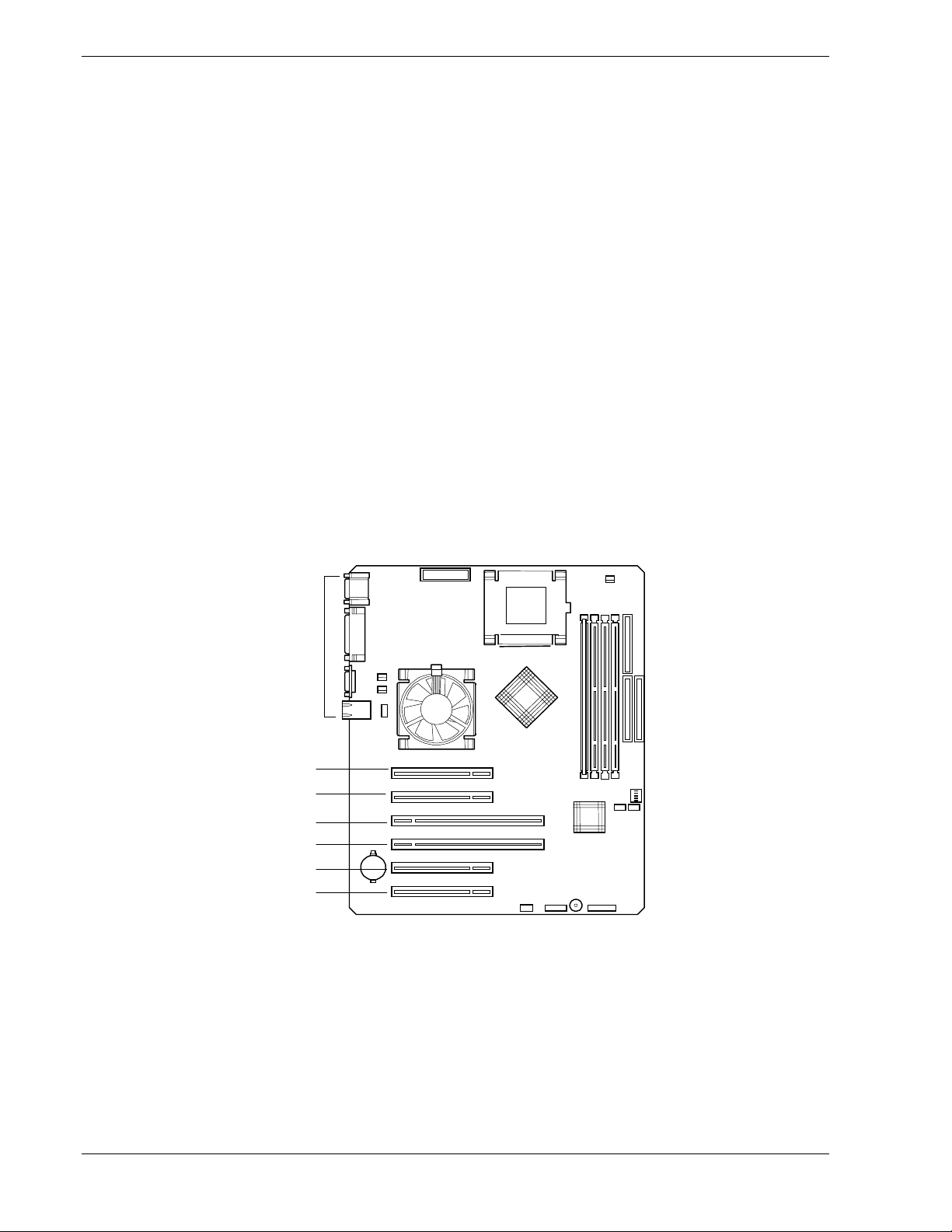
I/O Expansion Slots
Your server's expansion capabilities meet the needs of file and application servers for
high performance I/O by providing a combination of PCI expansion slots.
The I/O expansion slots in your server are located on the system board. See Figure 1-4.
The system board has two 66 MHz PCI connector slots that accommodate 64-bit PCI
cards and four 33 MHz PCI connector slot that accommodate 32-bit PCI cards.
PCI features:
Bus speed up to 66 MHz (PCI 3 and PCI 4)
!
64-bit memory addressing (PCI 3 and PCI 4)
!
32-bit memory addressing (PCI 1, PCI 2, PCI 5, and PCI 6)
!
5 V/3.3 V signaling environment
!
Burst transfers up to a peak of 264 MB/s (64 bit, 66 MHz PCI)
!
8-, 16-, 32-, or 64-bit data transfers
!
Plug and Play ready
!
Parity enabled.
!
1-8 System Overview
Slot 1
Slot 2
Slot 3
Slot 4
Slot 5
Slot 6
Figure 1-4. PCI Connector Slots
Page 23

IDE Controller
The system includes a dual channel enhanced IDE 32 bit interface controller for
intelligent disk drives with disk controller electronics onboard. The IDE controller
provides support for the internally mounted CD-ROM.
The device controls:
PIO and DMA transfer modes
!
Mode 4 timings
!
Transfer rates up to 33 MB/s
!
Buffering for PCI/IDE burst transfers
!
Keyboard and Mouse Controller
The keyboard and mouse controller is PS/2 compatible.
Network Controller
The system board includes a 10BASE-T/100BASE-TX network controller based on the
Intel 82559 Fast Ethernet PCI Bus Controller. As a PCI bus master, the controller can
burst data at up to 132 MB/sec. The controller contains two receive and transmit FIFO
buffers that prevent data overruns or underruns while waiting for access to the PCI bus.
The controller has the following:
32-bit PCI bus master interface (direct drive of bus), compatible with PCI Bus
!
Specification, Revision 2.1
Chained memory structure with improved dynamic transmit chaining for
!
enhanced performance
Programmable transmit threshold for improved bus utilization
!
Early receive interrupt for concurrent processing of receive data
!
On-chip counters for network management
!
Autodetect and autoswitching for 10 or 100 Mbps network speeds
!
Support for both 10 Mbps and 100 Mbps networks, capable of full or half
!
duplex, with back-to-back transmit at 100 Mbps.
Support for Wake On LAN.
!
Video Controller
The system has an integrated ATI RAGE XL 64 bit high-performance SVGA
subsystem that supports the following:
BIOS compatibility with VGA, EGA, CGA, Hercules Graphics, and MDA
!
8 MB of 10ns onboard Synchronous Graphics Memory (SGRAM)
!
System Overview 1-9
Page 24

Pixel resolutions up to 1280 X 1024
!
Analog VGA monitors (single and multiple frequency, interlaced and non-
!
interlaced) with a maximum vertical retrace non-interlaced frequency of
100 Hz.
Peripheral Controller
The advanced integrated peripheral controller supports two serial ports, two universal
serial ports, one parallel port, diskette drive, PS/2-compatible keyboard and mouse, and
integrated Real Time Clock (RTC). The system provides the connector interface for
each port.
Serial Ports
Both serial ports are relocatable. Each serial port can be set to one of four different
addresses and can be enabled separately. When disabled, serial port interrupts are
available to add-in boards.
Parallel Port
One IEEE 1284-compatible 25-pin bi-directional EPP (supporting levels 1.7 and 1.9)
parallel port is provided. BIOS programming enables the parallel port and determines
the port address and interrupt. ECP mode is supported with 2 possible DMA channels.
When disabled, the interrupt is available to add-in boards.
External Device Connectors
The external I/O connectors provide support for a PS/2 compatible mouse and a
keyboard, for a SVGA monitor, 2 serial port connectors, a parallel port connector, LAN
port, and two USB connections.
ACPI
The Advanced Configuration and Power Interface (ACPI) aware operating system can
place the system into a state where the hard drives spin down, the system fans stop, and
all processing is halted. However, in this state the power supply is still on and the
processors are still dissipating some power such that the power supply fan and
processor fans are still running.
Note: ACPI requires an operating system that supports its
feature.
This server system BIOS supports sleep states s0, s1, s4, and s5. However, with future
versions of Microsoft Windows 9X that support ACPI, the system BIOS only supports
sleep states s0, s1, and s5. With future versions of Microsoft Windows NT that support
ACPI, the system BIOS will only support sleep states s0, s1, s4, and s5.
1-10 System Overview
Page 25

Only when the AC power is disconnected is the system completely
off.
The sleep states are defined as follows:
s0: Normal running state.
!
s1: Processor sleep state.
!
No context will be lost in this state and the processor caches will maintain
coherency.
s4: Hibernate or Save to Disk.
!
The memory and machine state are saved to disk. Pressing the power button or
other wakeup event restores the system state from the disk and resumes normal
operation. This assumes that no hardware changes have been made to the system
while it was off.
s5: Soft off.
!
Only the RTC section of the chipset and the BMC are running in this state.
AC Link Mode
The AC link mode allows the system to monitor its AC input power so that when the
AC input power is lost and then restored the system will return itself to one of three preselected settings, listed as follows:
!
CAUTION
Power On
!
Last State (Factory Default Setting)
!
Stay Off.
!
The AC link mode settings can be changed by running the BIOS Setup Utility (F2).
Refer to Chapter 3 "Configuring Your System."
System Overview 1-11
Page 26

Remote Power-On (Wake ON LAN) Function
The remote power-on function turns on the system power by way of a network or
modem. If the system power is set to OFF, it can be turned on remotely by sending a
specific packet from the main computer to the remote system. This feature can be
enabled or disabled using the BIOS Setup Utility. See Chapter 3.
Note: This feature must be supported by your operating system.
Degradation Feature
The degradation feature automatically isolates a failed DIMM, processor, or cooling fan
to assure continuous operation of the server. The failed DIMM, processor, or cooling
fan is detected and isolated during POST (Power On Self-Test, self-diagnosis program
after power on). POST runs automatically during system startup.
Failed DIMMs, processors, and cooling fan may be identified by a POST error code
display, or by viewing NEC ESMPRO error messages.
System Security
Security with Mechanical Locks and Monitoring
To help prevent unauthorized entry or use of the system, the system includes a fully
lockable side panel.
Software Locks via the System Setup Utility
The BIOS Setup Utility provides a number of security features to prevent unauthorized
or accidental access to the system. Once the security measures are enabled, access to the
system is allowed only after the user enters the correct password(s). For example:
Enable the keyboard lockout timer so that the server requires a password to
!
reactivate the keyboard and mouse after a specified time-out period 2 to
120minutes.
Set and enable an administrative password.
!
Set and enable a user password
!
Set secure mode to prevent keyboard or mouse input and to prevent use of the
!
front panel reset and power switches.
Activate a hot-key combination to enter secure mode quickly.
!
Disable writing to the diskette drive when secure mode is set.
!
1-12 System Overview
Page 27

Setting Up the System
!
Overview
!
Selecting a Site
!
Unpacking the System
!
Getting Familiar with the System
!
Making Connections
!
Connecting the Power Cord
!
Powering On Your System
2
Page 28

Overview
This chapter describes how to select a site, make cable connections, and power
on the system. Information on front and rear panel features, switches and LEDs
are also included in this chapter.
Selecting a Site
The system operates reliably in a typical office environment.
Choose a site that is:
Near grounded, three-pronged power outlets.
!
Note
: For the United States and Canada, this means a
NEMA 5-15R outlets for 100-120 VAC or NEMA 6-15R
outlets for 200-240 VAC. For other international sites, this
means three-pronged power outlets applicable for the
electrical code of the region.
Be sure the power service connection is through a properly
grounded outlet.
!
WARNING
Clean, dust-free, and well ventilated. Front and rear ventilating openings
!
kept free of obstructions. Away from sources of heat, vibration or
physical shock.
Isolated from strong electromagnetic fields and electrical noise produced
!
by electrical devices (such as air conditioners, large fans, large electric
motors, radio and TV transmitters, and high-frequency security devices)
Spacious enough to provide at least five inches (13 centimeters) behind
!
the system and three inches (eight centimeters) on each side of the system
for proper cooling, airflow, and cable clearance.
Easily accessible for system maintenance and installation of system
!
upgrades.
2-2 Setting Up the System
Page 29

Unpacking the System
!
WARNING
Your system weighs approximately 45 pounds (20.41 kg). If
your system contains numerous optional boards and
peripheral devices, it will weigh more. To avoid personal
injury, make sure you have someone help you lift or move
the system.
When you receive your system, inspect the shipping containers prior to
unpacking. If the shipping boxes are damaged, note the damage, and if possible,
photograph it for reference. After removing the contents of the containers, keep
the cartons and the packing materials. If the contents appear damaged when you
unpack the boxes, file a damage claim with the carrier immediately.
Setting Up the System 2-3
Page 30
Getting Familiar with the System
Before setting up your system, you should become familiar with the system’s
features, such as the location of your system's front and rear panel switches,
indicators and connectors, etc. Note that this section describes the tower-based
system controls (switches and indicators) and connectors, which are identical for
the rack-mount system.
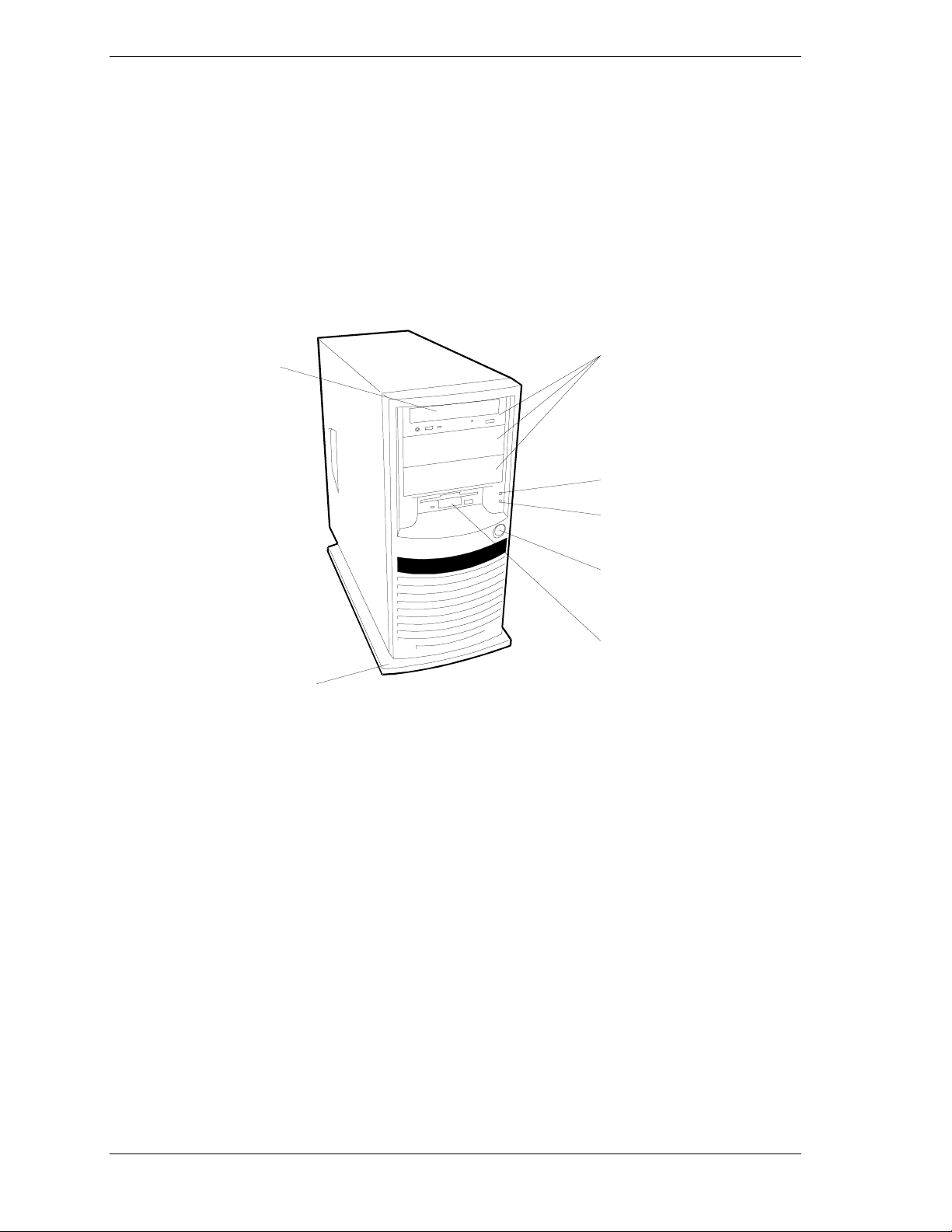
Front View
Figure 2-1 shows the location of the front system features (tower-based system).
A
B
C
D
E
F
G
A. CD-ROM drive Use this drive to read data from CD-ROM media.
B. 5.25-inch device
bays
POWER/SLEEP
C.
lamp
Use these bays to mount optional devices such as a DAT (digital audio tape)
drive or magneto-optic disk drive.
Lights green when the power is turned on. Flashes while the server is
operating in power saving mode (sleep state) when the operating system
supports the power-saving feature.
D. Disk access lamp Lights while the internal disk is in operation. This lamp does not indicate the
status of a device connected with an optional board (e.g., disk array board).
E. POWER switch Press this switch to power the server ON or OFF. Pressing the switch once
lights the POWER/SLEEP lamp to indicate that the server is on. Pressing the
switch again turns the server OFF. To forcibly shut down the server, press the
switch for 4 seconds or more.
3.5-inch floppy
F.
diskette drive
G. Stabilizer Stabilizes the server, preventing it from tipping over.
Use this drive to write/read data to/from a 3.5-inch floppy disk.
Figure 2-1. Front Features
2-4 Setting Up the System
Page 31

Rear View
Figure 2-1 shows the location of the following rear system features and controls.
E
FG
D
C
B
A
H
I
J
M
A SVGA monitor
connector
B Mouse connector PS/2-compatible 6-pin mini-DIN connector (Green)
C Keyboard
connector
D Dump Switch Press this switch to collect server event logs.
E Serial port 1 (right)
Serial port 2 (left)
F AC input power
connector
G Power supply 264 watt, auto-sensing power supply
H Printer port Parallel port 25-pin connector (Burgundy)
I 100/10 lamp Indicates the LAN transfer rate
J Link/ACT Indicates LAN access status
K PCI board slots PCI add-in board slot locations (6)
L LAN connector RJ-45 Ethernet connector
SVGA monitor 15-pin connector (Blue)
PS/2-compatible 6-pin mini-DIN connector (Purple)
COM1 serial port 9-pin connector (Turquoise)
COM2 serial port 9-pin connector (Turquoise)
Supplies ac power to the power supply
KL
M USB1 connector
USB2 connector
First USB connector (Black)
Second USB connector (Black)
Figure 2-2. Rear Features
Setting Up the System 2-5
Page 32

Making Connections
If your system normally operates without a video display or keyboard (for
example, as a network server), you must install a video display and keyboard to
configure the system. You may remove them after running the BIOS Setup
Utility. For information on running the BIOS Setup Utility, refer to Chapter 3
"Configuring Your System" of this User’s Guide.
Refer to Figure 2-3 and connect your keyboard, monitor, and mouse. Connect
any external peripheral devices such as a printer or modem by following the
instructions included with these devices.
!
Damage to the system may result if the keyboard/mouse
cable is inserted or removed when power is applied to the
system.
Inserting a telephone line connector into a LAN board RJ-45
port may result in personal injur y and equi pment damage.
CAUTION
1
2
2
1
2-6 Setting Up the System
Figure 2-3. Making Connections
Page 33

Connecting the Power Cord
Plug the female end of the AC power cord into the input receptacle on the rear
of the power supply cage. Plug the male end of the power cord into NEMA 515R outlet for 100-120 VAC or NEMA 6-15R outlet for 200-240 VAC.
If the power cord supplied with the system is not compatible with the AC wall
outlet in your region, obtain a suitable power cord that meets the following
criteria.
The power cord must be rated for the available AC voltage and have a
!
current rating that is at least 125% of the current rating of the system.
The power cord connector that plugs into the wall outlet must be
!
terminated in a grounding-type male plug designed for use in your region.
It must have certification marks showing certification by an agency
acceptable in your region.
The power cord connector that plugs into the system must be an IEC-
!
type CEE-22 female connector.
The power cord must be less than 1.8 meters (6.0 feet) long.
!
When connecting the power cord to a power control unit such as an UPS,
confirm that the power control unit is powered off. Connecting the power cord
while power is supplied to the power control unit may cause a failure.
!
WARNING
Your system shipped with a power cord for the power
supply. Do not attempt to modify or use the supplied AC
power cord if it is not the exact type required.
Setting Up the System 2-7
Page 34

Powering On Your System
Power on your system as follows.
1. Make sure all external devices, such as a video display, keyboard, and
mouse have been connected, and the power cords are connected.
2. Power on the video display and any other external devices.
3. Press the push-button power on/off switch on the front panel. Verify that the
system power-on LED is lit. See Figure 2-1 for the location of the power-on
LED.
Note:
board monitors and logs system voltage changes. When
powering up or down your system you ma y experience a
1–5 second delay from the time you press the push-button
power on/off switch on the front panel and your system
powering down. This is normal system operation and is
required by the server management logic.
The server management logic on your system
After a few seconds your system begins the internal Power-On Self Tests
(POST). POST automatically checks the system board, CPU module, memory,
keyboard, and most installed peripheral devices.
!
CAUTION
Always allow POST to complete before powering down your
system.
If you have problems powering on your system, refer to Problem Solving in
Chapter 5 of this User’s Guide.
After you have successfully powered on your system, insert the
E
XPRESSBUILDER
follow the screen prompts to run E
CD-ROM into the CD-ROM device, reboot the system and
XPRESSBUILDER
.
2-8 Setting Up the System
Page 35

Configuring Your System
!
Configuring Your System
!
BIOS Setup Utility
!
Configuring System Board Jumpers
3
Page 36

Configuring Your System
Configuration and setup utilities are used to change your system configuration.
You can configure your system, as well as option boards you may add to your
system, using the BIOS Setup Utility. Several unique system parameters are
configured using the BIOS Setup, which is stored in the system FLASH
memory.
If your system has been factory configured, the BIOS Setup does not need to be
run unless you want to change the password or security features, add certain
types of option boards or devices, or upgrade your system board.
This chapter also provides information on several system configuration
parameters that are set by jumpers on the system board. However, these
parameters do not usually require change.
Use the E
XPRESSBUILDER
CD-ROM to create the device driver diskettes.
3-2 Configuring Your System
Page 37

BIOS Setup Utility
The BIOS Setup Utility is used to change system configuration parameters. The
utility is resident in the system FLASH memory and does not require a diskette
or an operating system present to run.
Using the BIOS Setup Utility
You access the BIOS Setup utility when you turn on or reboot your system. To
run the BIOS Setup Utility, perform the following procedure:
1. Power-on or reboot the system. “Press <F2> to enter SETUP” displays.
2. Press F2. The BIOS Setup Utility starts and the Main Menu is displayed.
The menu bar at the top of the Main Menu lists the following selections:
Menu Use
Main Use this menu for basic system configuratio n.
Advanced Use this menu for setting the Advanced Features available on
your system.
Security Use this menu to set User and Supervisor Passwords and the
Backup and Virus-Check reminders.
System Hardware Use this menu for configuring unique Server features.
Boot Use this menu to configure Boot Device priority.
Exit Exits the current menu.
Use the arrow keys to select a menu or an item on a displayed menu. Press
the value keys (listed in the table below) to cycle through the allowable
values for the selected field. Use the Exit menu’s “Save Values” selection to
save the current values on all the menus.
To display a submenu, position the cursor on a selection that has a submenu
and press ENTER. An arrow precedes selections with submenus.
Refer to the following table for information on the keys that you use with
BIOS Setup. These keys are also listed at the bottom of the Setup menu.
Configuring Your System 3-3
Page 38

Key Function in Setup Menu
F1 or Alt-H Get Help about an item.
ESC Exit the current menu and return to the previous menu.
Left or right arrow keys Move between menus.
Up or down arrow keys Move cursor up and down. The cursor moves only to the
settings that you can change.
HOME or END Move cursor to top or bottom of window.
PAGE UP or PAGE DOWN Move cursor to next or previous page.
F5 or - Select the previous value for the field.
F6 or + or SPACE Select the next value for the field.
F9 Load default configuration values for this menu.
F10 Save configuration values and exit.
ENTER
Execute command or Select ➨ submenu.
BIOS Setup Configuration Settings
The BIOS Setup Configurations tables show the default settings for the BIOS
Setup Utility and provides a place for you to record any changes you make to
these settings. Recommended values are bold in the following tables.
3-4 Configuring Your System
Page 39

Main Menu
Choices or
Feature
Processor Type ——————— (Display Only). Shows the
Processor Speed 1.26GHz (Display Only). Indicates the
Cache RAM 512KB (Display Only). Indicates the
System Memory 640KB (Display Only). Indicates the
Extended Memory 131072KB (Display Only). Indicates the
Display Only Description Your Setting
type of processor installed.
processor speed.
cache RAM size.
total capacity of the basic
memory.
total capacity of the extended
memory.
Language
BIOS Version Rel. X.X.XXXX
System Time HH:MM:SS Sets the system time (hour,
System Date MM/DD/YYYY
Diskette A 1.44/1.25 MB 3.5" Selects the diskette type.
Primary Master XXXXMB (view only)
Primary Slave XXXXMB (view only)
Secondary Master CD-ROM (view only)
English (US)
French, German
Spanish, Italian
Selects which language BIOS
displays.
Note: This feature
immediately changes to the
language BIOS selected.
(Display Only). Indicates the
version of the system BIOS.
minutes, seconds, on 24 hour
clock).
Sets the system date (month,
day, year).
Note that 1.25 MB, 3.5 inch
references a 1024 byte/sector
Japanese media format. To
support this type of media
format requires a 3.5 inch
3-mode diskette drive.
Secondary Slave None (view only)
Configuring Your System 3-5
Page 40

Advanced Menu
Feature Description Your Setting
Advanced Refer to Advanced Submenu.
Memory Reconfiguration
CPU Reconfiguration Refer to CPU Rec onfiguration
Peripheral Configuration Ref er to Peripheral Reconfiguration
PCI Device Refer to PCI Device Submenu.
Option ROM Refer to Option ROM Submenu. I t
Numlock
Advanced Submenu
Feature
Installed O/S Other
Refer to Memory Reconfigur ation
Submenu.
Submenu.
Submenu.
Disables/Enables the Option ROM
BIOS on the PCI Bus.
Refer to Numlock Submenu. It selects
Keyboard Options.
Choices or Display
Only Description Your Setting
PnP O/S
Select “Other” to use Windows
NT. Select PnP O/S to use
Windows 2000. Note: An
incorrect s etting can cause
some operating systems to
display unexpected behavior.
Reset Configuration
Data
Boot-time Diagnost ic
Screen
RomPilot Support Disabled
Post Error Pause
No
Yes
Disabled
Enabled
Enabled
Disabled
Enabled
Memory Reconfiguration Submenu
Select Yes if you want to clear
the Extended System
Configuration Data (ESCD)
area.
Disables or enables display of
the diagnostic screen during
boot instead of the NEC logo.
The Boot-time diagnostic screen
is automatically enabled if
redirection or RomPilot is
enabled.
Disables or enables RomPilot
support. The Boot-t ime
diagnostic screen is enabled if
RomPilot is enabled.
Disables or enables a pause
during system bootup i f an error
occurs. If Enabled and an error
occurs, the bootup sequence
pauses and offers the choice of
entering BIOS Setup or
resuming the boot sequ ence. If
Disabled, the system always
continues to bootup.
Choices or
3-6 Configuring Your System
Page 41

Feature Display Only Description Your Setting
DIMM Group #1 Status Normal* (Display Only)
DIMM Group #2 Status Normal* (Display Only)
DIMM Group #3 Status Normal* (Display Only)
DIMM Group #4 Status Normal* (Display Only)
Clear DIMM Errors
DIMM Error Pause
*Possible Values: Normal, None, or Error.
Press ENTER
Enabled
Disabled
Clears the DIMM group error
status information.
The POST operation pauses if
a DIMM error occurs.
CPU Reconfiguration Submenu
Choices or
Feature
CPU #1 Status Normal* (Display Only)
CPU #2 Status Normal* (Display Only)
Clear CPU Errors
CPU Error Pause
*Possible Values: Normal, None, or Error.
Display Only Description Your Setting
Press ENTER
Enabled
Disabled
Clears the CPU error
information.
The POST operation pauses if
a CPU error occurs.
Peripheral Configuration Submenu
Choices or
Feature
Display Only Description Your Setting
Serial Port 1:
(COM 1)
Serial Port 2:
(COM 2)
Disabled
3F8, IRQ3
3F8, IRQ4
2F8, IRQ3
2F8, IRQ4
3E8, IRQ3
3E8, IRQ4
2E8, IRQ3
2E8, IRQ4
Auto
Disabled
3F8, IRQ3
3F8, IRQ4
2F8, IRQ3
2F8, IRQ4
3E8, IRQ3
3E8, IRQ4
2E8, IRQ3
2E8, IRQ4
Auto
Disables serial port 1 or
selects the base address and
interrupt (IRQ) for serial port 1.
Disables serial port 2 or
selects the base address and
interrupt (IRQ) for serial port 2.
Peripheral Configuration Submenu (Continued)
Choices or
Configuring Your System 3-7
Page 42

Feature Display Only Description Your Setting
Parallel Port Disabled
378, IRQ5
378, IRQ7
278, IRQ5
278, IRQ7
3BC, IRQ5
3BC, IRQ7
Auto
Parallel Mode Output only
Bi-directional
EPP
ECP, DMA1
ECP, DMA3
Diskette Controller Disabled
Enabled
Mouse
Disabled
Enabled
Auto Detect
Disables the parallel port or
selects the base address and
interrupt (IRQ) for the Parallel
port.
Selects the parallel port
operation mode.
Configure using these options:
(Disabled) No configuration.
(Enabled) User configuration
Disabled prevents any
installed PS/2 mouse from
functioning, but frees up
IRQ12.
Enabled forces the PS/2
mouse port to be enabled
regardless if a mouse is
present.
Auto Detect enables the PS/2
mouse only if present.
OS Controlled is displayed
only if the OS controls the
mouse.
LAN Controller
VGA Controller Disabled
USB Controller Disabled
Legacy USB
Support
IDE Controller
Disabled
Enabled
Enabled
Enabled
Disabled
Enabled
Both
Enable or disable the on-board
LAN controller.
Enable or disable the on-board
VGA controller.
Enables or disables the onboard USB controller.
Enable or disable the use of a
USB keyboard even if the OS
does not support USB. If set to
Enabled, the USB driver in
BIOS ROM is loaded at startup.
Enables or disables the onboard IDE controller.
3-8 Configuring Your System
Page 43

PCI Device Submenu
Feature
Choices or
Display Only Description Your Setting
PCI IRQ2
—
PCI IRQ15
Disabled
Auto Select
IRQ3
IRQ4
IRQ5
IRQ6
IRQ7
IRQ9
IRQ10
IRQ11
IRQ12
Option ROM Submenu
Choices or
Feature
Onboard LAN Enabled
PCI Slot 1
PCI Slot 2
Display Only Description Your Setting
Disabled
Enabled
Disabled
Enabled
Disabled
PCI devices use hard ware
interrupts called IRQs. A PCI
device cannot use IRQs already in
use by ISA devices. Use"Auto" only
if no ISA legacy cards are installed.
Disables/Enables the mapping of
the onboard LAN BIOS
Initializes Device Expansion ROM
Initializes Device Expansion ROM
PCI Slot 3
PCI Slot 4
PCI Slot 5
PCI Slot 6
Enabled
Disabled
Enabled
Disabled
Enabled
Disabled
Enabled
Disabled
Initializes Device Expansion ROM
Initializes Device Expansion ROM
Initializes Device Expansion ROM
Initializes Device Expansion ROM
Configuring Your System 3-9
Page 44

Numlock Submenu
Feature
Choices or
Display Only Description Your Setting
Numlock
Key Click
Keyboard Autorepeat Rate
Keyboard Autorepeat Delay
Auto
On
OFF
Disabled
Enabled
2/sec
6/sec
10/sec
13.3/sec
18.5/sec
21.8/sec
26.7/sec
30/sec
0.25 sec
0.5 sec
0.75 sec
1 sec
Selects the power-on state for
Numlock.
Disables or enables keyclick.
Selects key repeat rate.
Selects delay before key
repeat.
3-10 Configuring Your System
Page 45

Security Menu
Note:
Enabling the Supervisor Password field requires
a password for entering Setup. The passwords are not case
sensitive.
Feature
Supervisor PasswordisClear Status only, user c annot modify.
User Password is Clear Status only, user c annot modify.
Set Supervisor
Password
Choices or
Display Only Description Your Setting
Once set, this can be disabled by
setting it to a null string, or by clearing
password jumper on s ystem board
(see System Board Jumpers in this
Chapter).
Once set, this can be disabled by
setting it to a null string, or by clearing
password jumper on s ystem board
(see System Board Jumpers in this
Chapter).
Press ENTER Supervisor pass w ord controls access
to the setup utility.
When the <Enter> key i s pressed, the
user is prompted for a password;
press ESC key to abort. Once set, this
can be disabled by setting it to a null
string, or by clearing password jumper
on system board (ref er to System
Board Jumpers in thi s chapter).
Set User Password Press ENTER When the <Enter> key is pressed, the
Password on Boot Disabled
Diskette Access Everyone
Floppy Write Protect Write Protected
*Secure Mode Press ENTER
Power Switch Mask
Enabled
Supervisor
Normal
Masked
Unmasked
user is prompted for a password;
press ESC key to abort. Once set, this
can be disabled by setting it to a null
string, or by clearing password jumper
on system board (ref er to System
Board Jumpers in thi s chapter).
Disables or enables password entry
on boot.
Controls access to diskette drives.
Enable or disable dat a write to a
floppy disk in t he floppy disk drive
while the server is in the Secure
Mode.
Enable or disable the POWER switch
of the server. If "Masked" is selected,
power-off with the POWER switch
becomes unavailable after OS bootup. (Forced shut down also becomes
unavailable. Forc ed shut down is a
feature to shut down by pr essing the
POWER switch for at least four
seconds.)
* Only selectable when the user password is registered.
Configuring Your System 3-11
Page 46

Secure Mode
Feature
Choices or Display
Only Description Your Setting
Secure Mode Timer
Disabled
1 min
2 min
5 min
10 min
Select a time period to
place the server in the
Secure Mode after the last
keyboard or mouse
activity.
30 min
Secure Mode
Hotkey
1 hr
2 hr
Disabled
Enabled
Select "Disabled" to
prohibit the Secure Mode.
Enable or disable
activation of the Secure
Mode with a key entry.
Ctrl+Alt+ Any key Specify the key to use for
activating the Secure
Mode. Press the
specified key while
holding down the Ctrl and
Alt
to activate the Secure
Mode. Activation of the
Secure Mode with a key
entry is available when
"Enabled" is selected for
"Secure Mode Hotkey".
Secure Mode Boot
Disabled
Enabled
Specify whether to place
the server in the Secure
Mode at start-up.
System Hardware Menu
Feature
Thermal Sensor
Wake On Events Refer to Wake On Events
AC Link Power On
Error Log
Initialization
Console
Redirection
Choices or
Display Only Descript ion Your Setting
Refer to Thermal Sensor
Submenu.
Submenu.
Last State
Stay Off
No
Yes
Determines the mode of AC
Link.
Request to initialize the Error
Log now.
If Clear OK, then display
"System Event Log Cleared!"
If Clear NG, then display
"System Event Log Not
Cleared!"
Additional setup menu to
configure console.
The Boot-Time diagnostic
screen is enabled if redirection is
enabled.
3-12 Configuring Your System
Page 47

Thermal Sensor Submenu
Choices or
Feature
Display Only Description Your Setting
Thermal Sensor
Upper Limit 55
Lower Limit 5 Sets the lower temperature
Enabled
Disabled
When enabled determines if
the BIOS will disable boot (if
temperature is not within a
safe range).
Sets the upper temperature
limit in centigrade.
limit in centigrade.
Wake On Events Submenu
Choices or
Feature
Wake On LAN
Wake On Ring
Display Only Description Your Setting
Enabled
Disabled
Enabled
Disabled
Enables Wake ON LAN
support.
Enables Wake ON Ring
support.
Console Redirection Submenu
Choices or
Feature
Display Only Description Your Setting
Serial Port Address
Baud Rate 57.6K
Flow Control No Flow Control
Console
Connection
Disabled
Serial Port 2
(3F8h/IRQ4)
Serial Port 2
(2F8h/IRQ3)
19.2K
XON/XOFF
Direct
Via Modem
If enabled, the console will be
redirected to this port.
If console redirection is
enabled, this address must
match the settings of serial
port 2.
Enables the specified baud
rate.
Enables flow control.
Indicate whether the console is
connected directly to the
system or a modem is used to
connect.
Configuring Your System 3-13
Page 48

Boot Menu
Use the up or down arrow keys to select a device, then press the <+> or <->
keys to move the device higher or lower in the boot priority list.
Boot Device Priority Menu
Boot Priority Device Description Your Setting
1. ATAPI CD-ROM
Drive
2. Removable
Device
3. Hard Drive Attempts to boot from a hard
Attempts to boot from an
ATAPI CD-ROM drive.
Attempts to boot from a
diskette drive.
drive device.
3-14 Configuring Your System
Page 49

Exit Menu
You can make the following selections on the Exit Menu. Select an option
using the up or down arrow keys, then press <Enter> to execute the option.
Pressing <Esc> does not exit this menu. You must select one of the items from
the menu or menu bar to exit.
Exit Menu
Choices Description
Save Changes and Exit Exits System Setup after saving all changes to CMOS.
Exit Without Saving Changes Exits System Setup without saving setup data to CMOS.
Get Default Value Loads default values for all Setup items.
Load Previous Values Loads previous values of all Setup items.
Save Changes Writes all Setup item values to CMOS.
Configuring Your System 3-15
Page 50

Configuring System Board Jumpers
Before You Begin
Only a qualified technical person should perform the procedures in this section.
!
CAUTION
Electrostatic discharge (ESD) can damage the system
board. Modify the system board only at an ESD work s tation.
Otherwise, wear an antistatic wrist strap attached to chassis
ground.
The system board jumpers enable you to set specific operating parameters for
your system. A jumper is a small plastic-encased conductor (shorting plug) that
slips over two jumper pins.
Figure 3-1, A shows the location of the system board jumpers. Table 3-1 lists
the system board jumpers and their factory default settings.
1197531
12 10 8 6 4 2
A
Figure 3-1. System Board Jumpers
Table 3-3. System Board Jumper Summary
Jumper Function
1 - 2 CMOS clear Off, Protect
3 - 4 Password disable
5 - 6 Reserved Off, Not Used Required. Do Not Change.
7 – 8 Reserved Off, Not Used Required. Do Not Change.
9 – 10 Reserved Off, Not Used Required. Do Not Change.
Jumper On/Off
(default in bold) What it does at system reset.
On, Erase
Off, Enable
On, Disable
Preserves the contents of CMOS.
Clears CMOS.
Enables passwor d protection.
Disables the password.
11 - 12 Spare Off, Not Used
3-16 Configuring Your System
On, Spare
Provides a spare jum per storage location.
Page 51

Moving System Board Jumpers
!
Before doing the procedures in this section, make sure that
your system is powered off and unplug the AC power cord
from the back of the chassis. Failure to disconnect power
before moving the jumpers can result in personal injury and
equipment damage.
Observe static precautions. Use an antistatic wrist strap.
To configure the system board options:
1. Power off the system and remove the left panel as described in Chapter 4 of
this guide.
2. Check to ensure the system power cord is removed from the back of the
system.
3. Locate the position of the jumpers on the system board you are changing.
See Figure 3-1. To change a jumper setting, use a pair of needle-nose pliers
or your fingers to remove the jumper from its current location. Position the
jumper over the two pins for the desired setting and press it onto the pins. Be
careful not to bend the pins. Refer to Table 3-3 for system board jumper
settings.
CAUTION
4. Install the system cover and power up the system.
Configuring Your System 3-17
Page 52

Clearing and Changing the Passwords
To clear and change the passwords:
1. Power off the system and remove the left side panel as described in
Chapter 4 of this guide.
2. Check to ensure the system power cord is removed from the back of the
system.
3. Remove the spare jumper from position 11 - 12 on jumper block.
4. Reinstall the spare jumper on position 3 - 4 (Password Disable) of the
jumper block. Refer to Figure 3-1 and Table 3-1 to find the location of this
jumper.
5. Connect the power cord, power on the system and while waiting for POST
to complete, press the F2 key to enter BIOS setup. This automatically clears
all passwords, provided you exit and save the BIOS setup.
6. Power off the system and remove the power cord.
7. Remove the Password Disable jumper from pins 3-4 and store it in position
11 - 12.
8. Replace the left side panel, connect the power cord and power on the
system.
9. To specify a new password run the BIOS Setup Utility as described earlier
in this chapter.
3-18 Configuring Your System
Page 53

Clearing CMOS
Clear CMOS as follows.
1. Power off the system and remove the left side panel as described in
Chapter 4 of this guide.
2. Check to ensure the system power cord is removed from the back of the
system.
3. Remove the spare jumper from position 11 - 12 on jumper block.
4. Reinstall the spare jumper on position 1 - 2 (CMOS Clear) of the jumper
block. Refer to Figure 3-1 and Table 3-1 to find the location of this jumper.
5. Connect the power cord, power on the system and after POST completes,
power down the system and unplug the power cord.
6. Remove the jumper from pins 1-2 and store the jumper on pins 11-12.
7. Replace the left side panel, connect the power cord and power on the
system.
8. Press F2 at the prompt to run the BIOS Setup Utility, and select “Get
Default Values” at the Exit menu.
Configuring Your System 3-19
Page 54

Page 55

Upgrading Your System
!
General Information
!
Static Precautions
!
Preparing Your System for Upgrade
!
Equipment Log
!
Removing the Side Panels
!
Installing Side Panels
!
Modifying the System Board
!
Option Boards
4
!
Cable Protector
!
Hard Disk Drives
!
Front Panel
!
Removing EMI Shields and Filler Panels
!
Removable Media Devices
Page 56

General Information
!
The DC push-button on/off switch on the front panel does
not turn off the system AC power. Also, +5vdc is present on
the system board whenever the AC power cord is connected
between the system and an AC outlet. Before doing the
procedures in this manual, make sure that your system is
powered off and unplug the AC power cord from the back of
the chassis. Failure to disconnect power before opening
your system can result in personal injury and equipment
damage.
The server management logic on your system board
monitors and logs system voltage changes. When powering
down your system you may experience a 1–5 second delay
from the time you press the push-button power on/off switch
on the front panel and your system powering down. This is
normal system operation and is required by the server
management logic.
WARNING
!
CAUTION
Operating your system with the side panels removed can
damage your system components. For proper cooling and
airflow, always replace the side panels before powering on
your system.
Note:
Your system error log will be lost, if your s ystem
ac power source is off or disconnected.
Contact your sales representative or dealer for a list of approved optional
peripheral devices.
Static Precautions
An electrostatic discharge (ESD) can damage disk drives, option boards, and
other components. You can provide some ESD protection by wearing an
antistatic wrist strap attached to chassis ground when handling system
components.
Electronic devices can be easily damaged by static electricity. To prevent
damage, keep them in their protective packaging when they are not installed in
your system.
!
CAUTION
4-2 Upgrading Your System
Page 57

Preparing Your System for Upgrade
Depending on the upgrade, you will need one or more of the following tools:
Phillips screwdriver (#1 bit and #2 bit)
!
Flat-head screwdriver
!
Small needle nose pliers
!
Pen or pencil
!
ESD workstation or antistatic wrist strap (recommended).
!
Equipment Log
Use the equipment log form located at the end of this manual to record the
model and serial number of your system, all installed options, and any other
pertinent information specific to your system. You will need this information
when configuring your system.
Removing the Side Panels
To install options in your system, you must remove the side panel on the left
side of the system (as viewed from the front). The side panel on the right side of
the system (as viewed from the front) only has to be removed when adding
5.25-inch removable media devices to the system. Use this procedure for
removing either the right or the left side panel.
!
CAUTION
For proper cooling and airflow, do not operate the system
with the side panels removed. Always replace the panels
before powering on the system.
!
WARNING
If you are removing the side panel after the system is set up,
you must first power off the system and all external devices
and then Unplug the system power cord
To remove the left side panel:
1. Power off the system and ensure it is disconnected from the ac wall outlet.
2. The side panel is secured to the chassis with two locking tabs and two
screws. Slide the locking tabs on the side panel to "UNLOCK" positions to
unlock the panel.
3. Remove the screws securing the left side panel. Save the screws for
reattaching the side panel. See Figure 4-1.
Upgrading Your System 4-3
Page 58

4. Slide the side panel toward the rear of the chassis. This unlocks the locking
fingers behind the side panel.
5. Tilt the side panel out and away from the chassis.
2
1
Figure 4-1. Removing the Left Side Panel
Installing Side Panels
Unlock
Lock
Lock
Unlock
1. Before replacing the side panel, make sure no tools or loose parts have been
left inside the system chassis.
2. Make sure all option boards are firmly seated in their respective slots and
that all interior cables are properly connected.
3. Insert the metal tabs on the top and bottom of the side panel into their slots
on the chassis. Slide the side panel forward as far as it will go.
4. Slide the locking tabs on the side panel to "LOCK" positions to lock the
panel in place.
5. Replace the two side panel retaining screws.
Note: If your system is already set up, plug the system
back in, reconnect the peripherals, and power on the
peripherals and system.
4-4 Upgrading Your System
Page 59

Modifying the System Board
The following sections provide procedures for upgrading and configuring the
system board in your system. Topics covered include:
Replacing the real-time clock battery
!
Removing and installing a Pentium processor
!
Installing or removing DIMMs.
!
!
CAUTION
Electrostatic discharge (ESD) can damage add-in boards
and other components; place them on an antistatic surface.
Modify the system board only at an ESD workstation.
Otherwise, wear an antistatic wrist strap attached to chassis
ground.
Replacing the Real-time Clock Battery
You may need to replace the real-time clock battery because of its life span. The
battery (Vendor Part #CR2032) is a commodity part available through many
vendors. Notice the plus (+) sign on the battery. This sign will assist you in
correctly positioning the battery on the system board.
!
CAUTION
Danger of explosion if battery is incorrectly replaced.
Replace only with same or equivalent type recommended by
manufacturer. Dispose of lithium batteries as required by
local ordinance or as normal waste if no local ordinance
exists. Do not expose the component to excessive heat or
fire. Keep all batteries away from chi ldren
!
CAUTION
Observe static precautions. Use an antistatic wrist strap.
Upgrading Your System 4-5
Page 60

A
B
C
Figure 4-2. Replacing the Real-Time Clock Battery
1. Power off the system and ensure it is disconnected from the AC power
source.
2. Remove the left side panel as described earlier in this chapter.
3. If present, remove the protective plastic cover located over the top of the
lithium battery. See Figure 4-2.
4. Insert the tip of a small flat-bladed screwdriver (B), or equivalent, next to
the tab retainer (A).
5. Gently push on the tab to release the battery from its socket.
6. Remove the battery from its socket (C).
7. Dispose of the battery according to local ordinance.
8. Remove the new lithium battery from its package, and, being careful to
observe the correct polarity, insert it in the battery socket.
9. If applicable, reinstall the plastic cover on the lithium battery socket.
10. Replace the side panel, plug in the system power cord, and turn on the
system.
11. Run the BIOS Setup to restore the configuration settings to the real-time
clock.
4-6 Upgrading Your System
Page 61

Removing and Installing a Pentium III Processor
This subsection provides the procedures for removing and installing a
Pentium III processor in your system. The system board includes two
Pentium III ZIF sockets. The primary processor socket is shown in Figure 4-3,
A; the secondary processor socket is shown in Figure 4-3, C. The Pentium III
processor includes a heatsink and fan assembly to efficiently dissipate heat.
Figure 4-3, B shows the location for connection of the primary heatsink fan and
Figure 4-3, D shows the location for connection of the secondary heatsink fan.
!
CAUTION
Electrostatic discharge (ESD) can damage components;
place them on an antistatic surface. Modify the system board
using an antistatic wrist strap attached to chassis ground.
CD
B
A
Figure 4-3. Removing and Installing a Pentium III Processor
Removing a Processor
If the system has been running, any processor and heatsink
already installed on the board will be hot. To avo id the
possibility of a burn, let the components cool for 10 minutes
before continuing with the procedures described here
!
WARNING
1. Power off the system and ensure it is disconnected from the AC power
source.
2. Remove the left side panel as described earlier in this chapter.
Upgrading Your System 4-7
Page 62

3. Disconnect the processor fan power cable from the top of the heatsink fan
and the system board.
4. Insert a flat blade screwdriver into the tab of the retention clip securing the
heatsink of the processor you are removing. See Figure 4-4.
Figure 4-4. Removing the Heatsink Clip and Heatsink
!
CAUTION
When performing the remaining steps in this procedure, do
not touch the thermal tape located between the heatsink and
the processor as the tape is easily damaged.
5. Angle the screwdriver towards the heatsink as shown in Figure 4-4, and
while pushing downwards, release the heatsink clip from the tab of the ZIF
socket. Remove the heatsink and retention clip assembly.
6. Raise the ZIF socket lever to the up position. See Figure 4-5.
Figure 4-5. Removing the Processor
4-8 Upgrading Your System
Page 63

7. Grasp the opposite sides of the processor, apply equal upward force on each
side and rock it from side to side until it releases.
8. Place the processor into an antistatic container.
9. If you removed a processor from the secondary socket and do not intend to
replace it with a new processor, insert a processor terminator into the
secondary processor socket.
Installing a Processor
Observe static precautions. Use an antistatic wrist strap.
Hold the processor only by its edges.
Installing a second processor that is of a different type than
the first processor will result in system damage. Do not
touch or bend the processor's exposed pins.
!
CAUTION
!
CAUTION
Note:
system, you must remove the terminator from the secondary
processor socket.
Note:
replacing it, leave the terminator board intact in the empty
secondary processor connector. Remove the processor you
want to replace.
If you are adding a second processor to your
If your system has one processor and you are
1. Power off the system and ensure it is disconnected from the AC power
source.
2. Remove the left side panel as described earlier in this chapter.
3. Raise the ZIF socket lever to the up position. See Figure 4-5.
4. If you are adding a second processor to your system, remove the terminator
from the secondary processor socket.
5. Position the processor over its ZIF socket so the processor pins align with
the socket holes. Note that one corner of the processor has three pins that
should be positioned over the corner of the socket that has the three
matching pin holes. See Figure 4-6, A.
Upgrading Your System 4-9
Page 64

A
Figure 4-6. Positioning the Processor
6. Insert the processor pins into the socket. Apply pressure equally over the top
surface of the processor until it seats in the socket. The processor should
easily fit, do not force the processor into the socket.
7. Lower the ZIF socket lever into the locked position. See Figure 4-7.
Figure 4-7. Installing the Processor
The thermal tape is very delicate and tears easily. Handle
with extreme care.
4-10 Upgrading Your System
!
CAUTION
Page 65

A
Figure 4-8. Installing Thermal Tape
8. Position the heatsink above the processor so the thermal tape square
(Figure 4-8, A) attached to the bottom of the heatsink is directly positioned
above the processor.
!
CAUTION
When performing the next three steps, be sure the heatsink
is held firmly in position. If the heatsink should slide across
the top of the processor, the thermal tape may be damaged.
9. Position the heatsink clip over the center of the heatsink and attach the small
end of the clip to the tab located on the base of the ZIF socket. See Figure 49, A.
A
Figure 4-9. Positioning the Heatsink Clip
10. Insert a flat blade screwdriver into the tab of the retention clip.
11. Secure the clip onto the tab of the ZIF socket.
12. Connect the processor fan power cable to the processor heatsink fan and the
system board. See Figure 4-3, B and D for the location of the processor fan
power connectors.
Upgrading Your System 4-11
Page 66

DIMMs
13. Record the processor in the equipment log.
14. Replace the side panel, plug in the system power cord, and turn on the
system.
The system board contains four DIMM sockets labeled 1 through 4
(Figure 4-10, A). Each socket can hold a single 72-bit DIMM module with
128MB, 256MB, 512MB, or 1GB of memory. When all four sockets are
populated, the system board supports a maximum of 4 GB of memory with 1GB
DIMMs. A DIMM will always be installed in socket 1. When you install
additional DIMMs, you must start with the first empty socket next to the
DIMMs already installed. When you remove DIMMs, you must start with the
highest number occupied DIMM socket on the system board.
1324
Figure 4-10. DIMM Locations
A
4-12 Upgrading Your System
Page 67

Installing DIMMs
1. Power off the system and ensure it is disconnected from the AC power
source.
2. Remove the left side panel as described earlier in this chapter.
Observe static precautions. Use an antistatic wrist strap.
Hold DIMMs only by their edges.
3. If applicable, remove the dust cover from the DIMM socket in which you
are installing the DIMM.
4. Holding the DIMM module only by the edges, remove it from its antistatic
package.
5. Position the DIMM so that the two notches in the bottom edge of the DIMM
align with the keyed socket. See Figure 4-11.
!
CAUTION
1324
Figure 4-11. Inserting Memory DIMMs
6. Insert the bottom edge of the DIMM into the socket, and press down firmly
on the DIMM until it seats correctly.
7. Gently push the plastic ejector levers on the socket ends to the upright
position.
8. Repeat the steps to install each additional DIMM.
9. Replace the left side cover.
10. Plug in the server power cord, and power on the server.
Upgrading Your System 4-13
Page 68

Removing DIMMs
Use extreme care when removing a DIMM. Too much
pressure can damage the socket slot. Apply only enough
pressure on the plastic ejector levers to release the DIMM.
1. Power off the system and ensure it is disconnected from the AC power
source.
2. Remove the left side panel as described earlier in this chapter.
Observe static precautions. Use an antistatic wrist strap.
Hold DIMMs only by their edges.
3. Gently push the plastic ejector levers out and down to eject a DIMM from its
socket. See Figure 4-12.
!
CAUTION
!
CAUTION
1324
Figure 4-12. Removing Memory DIMMs
4. Hold the DIMM only by its edges, being careful not to touch its components
or gold edge connectors. Carefully lift it away from the socket, and store it
in an antistatic package.
5. Repeat the above steps to remove the remaining DIMMs.
6. If available, install a DIMM dust cover in any empty DIMM.
7. Replace the left side cover.
8. Plug in the server power cord, and power on the server.
4-14 Upgrading Your System
Page 69

Option Boards
This section describes how to install and remove PCI option boards. The system
board includes six PCI bus expansion slots. See Figure 4-13.
Observe static precautions. Use an antistatic wrist strap.
Hold the processor only by its edges.
Slot 1
Slot 2
Slot 3
Slot 4
Slot 5
Slot 6
!
CAUTION
Slot1 32-Bit/33 MHz/5V PCI Connector Slot
Slot2 32-Bit/33 MHz/5V PCI Connector Slot
Slot3 64-Bit/66 MHz/5V PCI Connector Slot
Slot4 64-Bit/66 MHz/5V PCI Connector Slot
Slot5 32-Bit/33 MHz/5V PCI Connector Slot
Slot6 32-Bit/33 MHz/5V PCI Connector Slot
Figure 4-13. PCI Slot Locations
Upgrading Your System 4-15
Page 70

Installing a PCI Option Board
1. Power off the system and ensure it is disconnected from the AC power
source.
2. Remove the left side panel as described earlier in this chapter.
3. Tilt the server on its side.
4. Using a flat blade screwdriver, bend and remove the expansion slot cover at
the location in which you are installing the option board. See Figure 4-14.
Figure 4-14. Removing the Expansion Slot Screw and Cover
!
CAUTION
Observe static precautions. Use an antistatic wrist strap.
4. Remove the screw from the PCI slot cover at the location in which you are
installing the option board.
5. Remove the option board from its protective wrapper, holding the board
only by the edges. Do not touch the board components or the gold
connectors.
6. Record the option board serial number in the equipment log.
7. Set any board jumpers or switches as described in the documentation that
comes with the option board.
8. Holding the board by its top edge or upper corners, firmly press the board
into an expansion slot on the system board. The tapered foot of the option
board retaining bracket must fit into the mating slot in the expansion slot.
See Figure 4-15.
4-16 Upgrading Your System
Page 71

Figure 4-15. Installing an Option Board
9. Align the rounded notch in the retaining bracket with the threaded hole in
the expansion slot frame. The retaining bracket fits into the space that was
occupied by the expansion slot cover.
10. Install the screw in the threaded hole. Be sure to push the bracket slot up
against the screw before you tighten it. If this is not done, the bracket may
interfere with an adjacent bracket.
11. Connect any external cables (if they are needed) to the installed option
board.
12. Tip the system upright and replace the left side panel.
13. Plug in the system power cord, and power on the system.
Removing an Option Board
Note:
vacant slots to maintain the electromagnetic emissions
characteristics of the system and to assure proper cooling of
the system components.
Expansion slot covers must be installed on all
1. Power off the system and ensure it is disconnected from the AC power
source.
2. Remove the left side panel as described earlier in this chapter.
3. Disconnect any cables attached to the option board you are removing.
4. Tilt the server on its side for easy access to the option board.
5. Remove the option board retaining bracket screw.
6. Hold the board at each end and carefully rock it back and forth until the edge
connectors pull free. Make sure that you do not scrape the board against
other components.
7. Remove the board from the expansion slot and place it in an antistatic
wrapper. If you are replacing a board, go to "Installing an Option Board"
earlier in this chapter, otherwise continue.
Upgrading Your System 4-17
Page 72

8. Tip the server upright.
9. Replace the left side panel, plug in the system power cord, and power on the
system
Cable Protector
Remove the cable protector before installing or removing a hard disk drive or
5.25-inch device.
Removing the Cable Protector
1. Power off the system and ensure it is disconnected from the AC power
source.
2. Remove the left side panel as described earlier in this chapter.
A
Figure 4-16. Installing an Option Board
3. Slide the cable protector to the left, gently pull it toward you, and remove
the cable protector.
Installing the Cable Protector
1. Install the cable protector so that the cable protector is fully contained in the
server frame. The sponge backing on backside of the cable protector should
be positioned towards the top of the server next to the 5 ¼-inch device cage.
2. Tip the server upright.
3. Replace the left side panel, plug in the system power cord, and power on the
system.
4-18 Upgrading Your System
Page 73

Hard Disk Drives
Your system supports up to two IDE 3.5-inch hard disk drives. Contact your
sales representative or dealer for a list of approved devices. The internal hard
disk drives are mounted in a cage located near the front of the system above the
front fan. See Figure 4-17, A).
A
Figure 4-17. Drive Bay Locations
Installing an Internal Hard Disk Drive
1. Power off the system and remove the left side panel as
described earlier in this chapter.
!
CAUTION
Observe static precautions. Use an antistatic wrist strap.
2. Tilt the server on its side.
3. Remove the cable protector as described earlier in this chapter.
4. Remove all the cables connected to any installed hard disk.
!
CAUTION
Pull out cables slowly and carefully. Note that your hand
may not hit on some surrounding components in the
disconnection. If so, the components may be damaged.
the power cable is hard to disconnect, first remove the hard
disk.
If
Upgrading Your System 4-19
Page 74

5. Lift the lock lever on the fan installed in the hard disk bracket lightly to
release the lock. See Figure 4-18.
Figure 4-18. Releasing the Fan lock Lever
6. Slide the fan with the lock released towards the top of the server to remove
the fan. See Figure 4-19.
!
CAUTION
Do not place the removed fan on the system board. If you
place the removed fan on the system board, some
components on the system board may be defected.
Figure 4-19. Removing the Fan
4-20 Upgrading Your System
Page 75

7. Remove four screws securing the hard disk drive cage to the system chassis.
See Figure 4-20.
A
A
Figure 4-20. Removing the Hard Disk Drive Cage Screws
8. Slide the hard disk bracket as shown in the figure below to remove the hard
disk bracket from the bracket for the floppy disk drive.
Figure 21. Removing the Hard Disk Drive Cage
Upgrading Your System 4-21
Page 76

9. Remove the disk drive from its protective wrapper and place it on an
antistatic surface. Record the drive model and serial number in the
equipment log.
10. Set any drive jumpers or switches before you install the drive. See the
documentation that comes with the device for jumper or switch information.
11. Insert the hard disk drive into the drive cage with the board surface facing
the bottom. See Figure 4-22.
Figure 4-22. Installing a Hard Disk Drive
Note:
varies depending on the type of the drive.
Install the first IDE hard disk drive in the top bay of the hard
disk bracket. Install the second IDE hard disk drive in the
third bay from the top. See Figure 4-23.
Figure 4-23. Position of IDE Hard Disk Drives in the Cage
The installation of a hard disk drive in the server
12. Secure the hard disk drive in the hard disk drive cage with the four screws
supplied. See Figure 4-24.
4-22 Upgrading Your System
Page 77

Figure 4-24. Securing the hard Disk Drive
13. Position the hard disk drive cage into the system. The four tabs on the top of
the hard disk drive cage insert into the four slots located on the bottom of the
floppy disk drive cage. See Figure 4-25.
Figure 4-25. Installing a Hard Disk Drive Cage
!
CAUTION
Hold the hard disk cage securely to avoid touching
components on the system board.
14. Secure the hard disk bracket with the four screws removed in step 7.
15. Install the fan removed in step 6 into the hard disk cage. See Figure 4-26.
Upgrading Your System 4-23
Page 78

16. Insert the four fan housing tabs into the fan installation slots on the hard disk
cage and slide the fan towards the bottom of the cabinet. The fan clicks as it
is locked in position.
Figure 4-26. Installing the Fan
17. Connect the power and interface cables to the hard disk drive (s).
Attach connector P10 of a power cable coming from the power supply to the
first (master) hard disk and connector P9 of another power cable to the
second (slave) hard disk.
Attach the interface cable connector with the black tag to the first (master)
hard disk drive and the connector with the gray tag to the second (slave)
hard disk drive (if applicable). See Figure 27.
Figure 4-27. Installing the Interface Cables
4-24 Upgrading Your System
Page 79

18. Install the cable protector as described earlier in this chapter.
19. Upright the server.
20. Install the left side panel as described earlier in this chapter and power on
the server.
Removing an Internal Hard Disk Driv e
1. Power off the system and remove the left side panel as described earlier in
this chapter.
!
CAUTION
Observe static precautions. Use an antistatic wrist strap.
2. Tilt the server on its side.
3. Remove the cable protector as described earlier in this chapter.
4. Remove all the cables connected to any installed hard disk.
!
CAUTION
Pull out cables slowly and carefully. Note that your hand
may not hit on some surrounding components in the
disconnection. If so, the components may be damaged.
the power cable is hard to disconnect, first remove the hard
disk.
If
5. Lift the lock lever on the fan installed in the hard disk bracket lightly to
release the lock. See Figure 4-18.
6. Slide the fan with the lock released towards the top of the server to remove
the fan. See Figure 4-19.
!
CAUTION
Do not place the removed fan on the system board. If you
place the removed fan on the system board, some
components on the system board may be damaged.
6. Remove four screws securing the hard disk drive cage to the system chassis.
See Figure 4-20.
7. Slide the hard disk bracket as shown in Figure 4-21 to remove the hard disk
bracket from the bracket for the floppy disk drive.
8. Remove the four screws securing the disk drive to the drive cage.
9. Slide the hard disk drive out of the drive cage.
10. Remove the drive model and serial number from the equipment log.
Upgrading Your System 4-25
Page 80

11. Follow steps 13 through 20 in the previous procedure “Installing an Internal
Hard Disk Drive” to complete this procedure.
Front Panel
The front panel is a one-piece assembly. The removable filler panels are
attached to the front panel and the corresponding EMI shields are attached to the
front of the chassis. If you are installing peripheral devices in the external bays
above the 3.5-inch floppy disk drive, you must remove the front cover along
with the corresponding filler panel and EMI shield.
Removing the Front Panel
Note: The front panel is secured with six locking tabs.
1. Power off the system and remove the left and right side panels
as described earlier in this chapter.
Observe static precautions. Use an antistatic wrist strap.
!
CAUTION
2. Remove the front panel by first releasing the three tabs that secure the panel
to the left side of the system chassis. Then release the tabs that secure the
panel to the right side of the chassis. See Figure 4-28.
Figure 4-28. Removing the Front Panel
4-26 Upgrading Your System
Page 81

Installing the Front Panel
1. Align the front panel tabs with the slots in the front of the chassis.
2. Press the front panel onto the front of the system chassis until the tabs snap
into their slots. See Figure 4-29.
3. Install the left and right side panels as described earlier in this
chapter and power on the server.
Figure 4-29. Installing the Front Panel
Upgrading Your System 4-27
Page 82

Removing EMI Shields and Filler Panels
1. Power off the system and remove the front panel as described earlier in this
chapter.
2. The filler panels are attached to the front cover. Locate the filler panel
covering the bay into which you are installing a peripheral device. The filler
panel is released by pressing on its tabs located on the inside of the front
panel. Save the panel for reinstallation. See Figure 4-30.
Figure 4-30. Removing a Filler Panel
3. Locate the EMI (Electromagnetic Interference) shield covering the bay into
which you are installing a peripheral device The EMI shield is attached to
the front of the chassis with two screws. Remove the screws and EMI shield
covering the bay into which you are installing a peripheral device. Save the
shield and screws for reinstallation. See Figure 4-31.
Figure 4-31. Removing an EMI Shield
4-28 Upgrading Your System
Page 83

Removable Media Devices
A variety of IDE removable media devices can be installed in peripheral bays B
and C. An IDE CD-ROM is always mounted in bay A. A 3.5-inch diskette drive
is always mounted in bay D. See Figure 4-32. Contact your sales representative
or dealer for a list of approved IDE devices.
BAY A
BAY B
BAY C
BAY D
Figure 4-32. Removable Media Device Locations
Installing a 5.25-Inch Device
!
CAUTION
CD-ROM devices contain a laser system and are classified
as CLASS 1 LASER PRODUCTS. To use these devices,
thoroughly read the documentation provided by the CDROM manufacturer, and keep the documentation for future
reference. In case of any trouble with a CD-ROM, please
contact your nearest service representative. To prevent
direct exposure to the laser beam, do not try to open the
enclosure. Use of controls or adjustments or performance of
procedures other than those specified in the CD-ROM
manufacturer's documentation may result in hazardous
radiation exposure
1. Power off the system and remove the side panels as described earlier in this
chapter.
2. Remove the front panel, EMI shield, and filler panel covering the bay into
which you are installing a peripheral device as described earlier in this
chapter.
!
CAUTION
Observe static precautions. Use an antistatic wrist strap.
3. Remove the device from its protective wrapper and place it on an antistatic
surface. Record the drive model and serial number in the equipment log.
Upgrading Your System 4-29
Page 84

4. Set any drive jumpers or switches before you install the drive. See the
documentation that comes with the device for jumper or switch information.
Note:
them. Remove any rails already attached.
If the drive comes with drive rails, do not use
5. Slide the drive into the bay until the screw holes line up. Align the front
cover of the installed device with the CDROM drive. It may be necessary to
temporarily loosen the mounting screws on already installed drives to
position the new drive. Secure the drive to the bay with the four supplied
screws. See Figure 4-33.
Power Cable
5.25" Drive
Figure 4-33. Installing a Removable Media Device
6. Connect the signal and power cables to the device as shown in Figure 4-33.
7. Replace the front panel and side panels, and power on the system.
4-30 Upgrading Your System
Page 85

Removing a 5.25-Inch Device
1. Power off the system and remove the side panels as described earlier in this
chapter.
2. Remove the front panel as described earlier in this chapter.
3. Disconnect the power cable (A) and ribbon data cable (B) from the device
you are removing. See Figure 4-34.
A
B
Figure 4-34. Removing a Removable Media Device
4. Remove and save the four screws from the device.
5. Install an EMI (Electromagnetic Interference) shield over the bay from
which you removed the peripheral device.
6. Install filler panel into the front panel over the bay from which you removed
the peripheral device.
7. Replace the side panels and front panel, and power on the system.
8. Remove the drive serial number from the equipment log.
Upgrading Your System 4-31
Page 86

Page 87

Problem Solving
!
Problem Solving
!
Static Precautions
!
Troubleshooting Checklists
!
Diagnostic Testing
!
Specific Problems and Corrective Actions
!
Problems with the Network
!
Plug and Play Installation Tips
!
BIOS User’s Information
5
!
How to Identify BIOS Revision Level
Page 88

Problem Solving
This chapter helps you identify and solve problems that may occur during system
installation or while using your system. The first section of this chapter tells you how to
reset your system in the event of problems. The next few sections provide
troubleshooting checklists and procedural steps that help you isolate specific system
problems. The last section includes BIOS, system, and disk status user information.
The DC push-button on/off switch on the front panel does not turn off
the system AC power. Also, +5vdc is present on the system board
whenever the AC power cord is connected between the system and
an AC outlet. Before doing the procedures in this manual, make sure
that your system is powered off and unplug the AC power cords from
the back of the chassis. Failure to disconnect power before opening
your system can result in personal injury and equipment damage
Operating your system with the side panels removed can damage
your system components. For proper cooling and airflow, always
replace the side panels before powering on your system.
!
WARNING
!
CAUTION
Static Precautions
An electrostatic discharge (ESD) can damage disk drives, option boards, and other
components. You can provide some ESD protection by wearing an antistatic wrist strap
attached to chassis ground when handling system components.
Electronic devices can be easily damaged by static electricity. To prevent damage, keep
them in their protective packaging when they are not installed in your system.
5-2 Problem Solving
Page 89

Troubleshooting Checklists
The following subsections provide troubleshooting checklists for problems that occur at
initial system startup, when you run new application software, and after the system
hardware and software have been running correctly.
Initial System Startup
Incorrect installation or configuration usually causes problems that occur at initial
system startup. Hardware failure is a less frequent cause. If you have problems during
initial system startup, check the following:
Is the system power cord properly connected to the system and plugged into a
!
NEMA 5-15R outlet (100-120 Vac) or a NEMA 6-15R outlet (200-240 Vac)?
Is AC power available at the wall outlet?
!
Is the power on/off push-button switch on the front panel in the ON position (power
!
on LED should be lit)?
Are all cables correctly connected and secured?
!
Are all the PCI option boards fully seated in their connector slots on the system
!
board?
Are all jumpers and switch settings on option boards and peripheral devices correct?
!
If applicable, ensure that there are no conflicts; for example, two option boards
sharing the same interrupt.
Are all DIMMs fully seated and installed correctly? Refer to Chapter 4 for
!
installation instructions?
Are all option boards and disk drives installed correctly? Refer to the Chapter 4.
!
Is the system hard disk drive properly formatted or defined?
!
Is the operating system properly loaded? Refer to the operating system
!
documentation.
Are all drivers properly installed? For information about installing drivers, refer to
!
your Network Operating System Configuration Guide.
Are the configuration settings in BIOS Setup and the Adaptec SCSI Utility correct?
!
For information about running these utilities, refer to the “Configuring Your
System” chapter.
If the above items are all correct, but the problem reoccurs, refer to “Additional
Troubleshooting Procedures” in this chapter.
Problem Solving 5-3
Page 90

Running New Application Software
Problems that occur when you run new application software are usually related to the
software. Faulty equipment is much less likely, especially if other software runs
correctly. If you have problems while running new application software, check the
following:
Does the system meet the minimum hardware requirements for the software? Refer
!
to the software documentation.
Is the software an authorized copy? Unauthorized copies often do not work. Obtain
!
an authorized copy of the software.
If you are running the software from a diskette, is it a good copy?
!
If you are running the software from a hard disk drive, is the software correctly
!
installed? Where all necessary procedures followed and files installed?
If you are running the software from a CD-ROM disk is the disk scratched or dirty?
!
Are the correct device drivers installed?
!
Is the software correctly configured for the system?
!
Are you using the software correctly?
!
If other software runs correctly on the system, contact your vendor about the failing
!
software.
If the problems persist with the software, contact the software vendor's customer service
representative.
5-4 Problem Solving
Page 91

After System Has Been Running Correctly
Problems that occur after the system hardware and software have been running
correctly often indicate equipment failure. However, many situations that are easy to
correct can also cause such problems. If you have problems after the system has been
running correctly, check the following:
If you are running the software from a diskette or CD-ROM, try a new copy of the
!
software.
If you are running the software from a hard disk drive, try running it from a floppy.
!
If the software runs correctly, there may be a problem with the copy on the hard
disk. Reinstall the software on the hard disk drive and try running it again. Make
sure all the necessary files are installed.
If the problem recurs, you may need to reformat the hard disk drive. The hard disk
!
drive, the drive controller, or the system board may be defective.
If the problems are intermittent, there may be a loose cable, dirt in the keyboard (if
!
keyboard input is incorrect), a marginal power supply, or other random component
failures.
If you suspect that a transient voltage spike, power outage, or brownout might have
!
occurred, reload the software and try running it again. Symptoms of voltage spikes
include a flickering video display, unexpected system reboots, and the system not
responding to user commands.
Note:
Voltage spikes can corrupt or destroy data files on the
drive. If you are experiencing voltage spikes on the power line, install
a surge suppresser between the power outlet and the system power
cord.
If the problem recurs after you have checked and corrected all of the above items, refer
to “Diagnostic Testing” in this chapter.
Problem Solving 5-5
Page 92

Diagnostic Testing
This section provides a more detailed approach to diagnostic testing and identification
of a problem and locating its source.
Error Checking
Each time you turn on the system, POST (Power-On-Self-Test) runs automatically and
checks the system boards, processors, memory, keyboard, and most installed peripheral
devices.
If POST finds an error, it displays an error message. Refer to the Error Message section
in this chapter for an explanation of each error message.
Troubleshooting Guide
Use the following troubleshooting procedures to help you identify a problem. These
general procedures lead you through the following:
Preparing the system for diagnostic testing
!
Monitoring POST while it is running
!
Verifying proper operation of key system LEDs
!
Confirming loading of the operating system.
!
Preparing the System for Diagnostic Testing
To prepare the system for diagnostic testing, perform the following:
Note:
system, turn off the system and any external peripheral devices.
Failure to do so can cause permanent damage to the system and/or
the peripheral devices.
Before disconnecting any peripheral cables from the
1. Turn off the system and all external peripheral devices. Disconnect all devices from
the system except the keyboard and video monitor.
2. Make sure the system power cord is plugged into a properly grounded AC outlet.
3. Make sure your video display monitor and keyboard are correctly connected to the
system. Turn on the video monitor. Set its brightness and contrast controls to at least
two-thirds of their maximum ranges (refer to the documentation supplied with your
video display monitor).
4. If the operating system normally loads from the hard disk drive, make sure there is
no diskette in drive A. Otherwise, place a diskette containing the operating system
files in drive A.
5. Turn on the system. If the power indicator LED does not light, refer to “Power
Light Does Not Light” found later in this chapter.
5-6 Problem Solving
Page 93

Monitoring POST
Each time you turn on the system, the Power-On Self-Test (POST) runs automatically
and checks the system board, processor board, memory, keyboard, and most installed
peripheral devices.
During the memory test, POST displays the amount of memory that it is able to access
and test. Depending on the amount of memory, it may take several minutes to complete
the memory test.
Press F2 to enter SETUP. If you do not press F2, the above message remains for a few
seconds and the boot process continues.
If POST finds an error, it displays an error message and, in case there is a problem with
the display, it emits a series of long and short beeps. Write down any beep code
emitted. This information is useful to your service representative.
Refer to the “BIOS User’s Information” section in this chapter for a list of items to
check for each error code and for an explanation of the error beep codes.
The POST Tests table at the end of this chapter lists keys active during POST and
provides a description of errors that may occur.
The BIOS indicates errors by writing an error code to the PS/2-standard logging area in
the Extended BIOS Data Area, and by displaying a message on the screen, which is
sometimes preceded by the POST Error Code. The error code will also be logged to the
Event Logging area.
Report any error code to your service representative.
Problem Solving 5-7
Page 94

POST Keys and Errors
Action/Message Description
If POST Beeps Before
Video Appears
If Monitor Displays Error
To Enter Setup Setup changes specific options, then writes to CMOS,
Enter BOOT Diskette If prompted, insert the boot diskette.
Initialization failed before video initialized. Most beep code
errors are fatal; initialization cannot continue. Refer to the
section “BIOS User’s Information” in this chapter.
Note error; press F1 to continue boot or F2 to enter Setup.
Refer to the section “BIOS User’s Information” in this chapter.
NVRAM. Press F2 during initialization to run Setup. If you do
not press F2, the boot process continues.
Verifying Proper Operation of Key System Indicators
As POST determines the system configuration, it tests for the presence of each mass
storage device installed in the system. As each device is checked, its activity indicator
should turn on briefly. Check for the following:
Does the diskette drive activity indicator turn on briefly? If not, refer to “Diskette
!
Drive Activity Indicator Does Not Light” in this chapter.
Does the hard disk drive activity indicator turn on briefly? If not, refer to “Hard Disk
!
Drive Activity Indicator Does Not Light” in this chapter.
Confirming Loading of the Operating System
Once the system boots up, the operating system prompt appears on the screen. The
prompt varies according to the operating system. If the operating system prompt does
not appear, refer to “Problems with Application Software” found later in this chapter.
5-8 Problem Solving
Page 95

Specific Problems and Corrective Actions
This section provides possible solutions for the following specific problems:
Power LED does not light
!
No beep or incorrect beep pattern
!
No characters appear on screen
!
Characters on the screen appear distorted or incorrect
!
System cooling fan does not rotate
!
Diskette drive activity LED does not light
!
Hard disk drive activity LED does not light
!
CD-ROM drive activity LED does not light
!
Problems with application software
!
The startup prompt “Press <F2> key if you want to run Setup” does not appear on
!
the screen.
The bootable CD-ROM is not detected.
!
Try the solutions in the order given. If you cannot correct the problem, contact your
service representative for assistance.
Power LED Does Not Light
Check the following:
Is the system operating normally? If so, the power LED is probably defective.
!
Are there other problems with the system? If so, check the items listed under System
!
Cooling Fans Do Not Rotate.
Problem Solving 5-9
Page 96

Incorrect or No Beep Code
If the system operates normally, but there was no beep, the piezo buzzer located on the
system board, may be defective. Contact your service representative for assistance.
Record the beep code emitted by POST, and see the “Messages and Beep Codes”
section found later in this chapter.
No Characters Appear on Screen
Check the following:
Is the keyboard working? Check to see if the Num Lock light is functioning.
!
Is the video display monitor plugged in and turned on?
!
Are the brightness and contrast controls on the video monitor properly adjusted?
!
Are the video monitor switch settings correct?
!
Is the video monitor signal cable properly installed?
!
Is the onboard video controller enabled?
!
If you are using a video controller board, verify that the video controller board is fully
seated in the system board connector.
If there are still no characters on the screen after you reboot the system, contact your
service representative or authorized dealer for assistance.
POST emits one long beep and two short beeps pattern to indicate a possible problem
with the video display controller. If you do not receive a beep pattern and characters do
not display, the video display or video controller may have failed. Contact your service
representative or authorized dealer for assistance.
5-10 Problem Solving
Page 97

Characters are Distorted or Incorrect
Check the following:
Are the brightness and contrast controls properly adjusted on the video display?
!
Refer to the documentation supplied with your video display.
Are the video monitor's signal and power cables properly installed?
!
If the problem persists, the video monitor may be faulty or it may be the incorrect
!
type. Contact your service representative for assistance.
System Cooling Fans Do Not Rotate
Check the following:
Is AC power available at the wall outlet?
!
Are the system power cords properly connected to the power supplies and the AC
!
wall outlets?
Are the power connectors for the cooling fans connected?
!
Is the front panel power on indicator lit?
!
If the switches and connections are correct and the power outlet is functioning, the
power supply has probably failed. Contact your service representative for assistance.
Diskette Drive Activity LED Does Not Light
Check the following:
Is the diskette drive's combined power and signal cables properly installed?
!
Is the diskette drive properly configured?
!
Is the diskette drive activity light always on? If so, the signal cable may be plugged
!
in incorrectly.
If you are using the onboard diskette drive controller, use BIOS Setup to make sure that
the diskette drive controller is set to Enabled. For information about running BIOS
Setup, refer to the “Configuring Your System” chapter.
If the problem persists, there may be a problem with the diskette drive, system board, or
drive signal cable. Contact your service representative for assistance.
CD-ROM Drive Activity Light Does Not Li ght
Check the following:
Is the power and signal cable to the CD-ROM drive properly installed?
!
Are all relevant switches and jumpers on the drive set correctly?
!
Is the drive properly configured?
!
Is the onboard IDE controller enabled?
!
Problem Solving 5- 11
Page 98

Problems with Application Software
If you have problems with application software, perform the following:
Verify that the software is properly configured for the system. Refer to the software
!
installation and operation documentation for instructions on setting up and using the
software.
Verify a different copy of the software to see if the problem is with the copy that you
!
are using.
Make sure all cables are installed correctly.
!
Verify that the system board jumpers are set correctly. Refer to the “Configuring
!
Your System” chapter for jumper settings.
If other software runs correctly on the system, contact your vendor about the failing
!
software.
If the problem persists, contact the software vendor's customer service representative
for assistance.
Bootable CD-ROM Is Not Detected
Check the following:
Is the BIOS set to allow the CD-ROM to be the second bootable device? Check your
!
BIOS Setup (F2) configuration.
Problems with the Network
Diagnostics pass, but the connection fails:
Make sure the network cable is securely attached. ACT/Link activity LED located on
!
the front panel should be blinking if there is activity between the system and the
network.
The controller stopped working when an add-in adapter was installed:
Make sure the cable is connected to the port from the onboard network controller.
!
Make sure the other adapter supports shared interrupts. Also, make sure your
!
operating system supports shared interrupts; OS/2 does not.
Try reseating the add-in adapter.
!
The add-in adapter stopped working without apparent cause.
Try reseating the adapter first; then try a different slot if necessary.
!
The network driver files may be corrupt or deleted. Delete and then reinstall the
!
drivers.
Run the diagnostics.
!
5-12 Problem Solving
Page 99

Plug and Play Installation Tips
Some common PCI tips are listed here.
Reserve interrupts (IRQs) and/or memory addresses specifically for an ISA adapter.
!
This prevents PCI cards from trying to use the same settings an ISA card is using.
Use the BIOS Setup Utility to keep track of ISA adapter resources.
Certain drivers may require interrupts that are not shared with other PCI drivers.
!
The BIOS Setup Utility can be used to adjust the interrupt numbers for PCI devices.
For certain drivers, it may be necessary to alter settings so that interrupts are not
shared.
BIOS User’s Information
This section describes the various screen messages and beep codes of the system BIOS.
The BIOS indicates errors by writing an error code to the PS/2-standard logging area in
the Extended BIOS Data Area, and by displaying a message on the screen, which is
sometimes preceded by the POST Error Code. The error code will also be logged to the
Event Logging area.
Note:
source is off or disconnected.
Your system error log will be lost, if your system ac power
Problem Solving 5- 13
Page 100

POST Error Codes and Messages
Whenever a recoverable error occurs during POST, BIOS displays a message on the
video display screen and causes the speaker to beep as the message appears. BIOS also
issues a beep code (one long tone followed by two short tones) during POST if the
video configuration fails or if an external ROM module does not a checksum of zero.
The “POST Error Codes and Messages” table is a list of the possible error codes and
messages written at the start of each POST test. The “POST Error Beep Codes” table is
a list of beep codes issued for each POST test. Figure 5-1 shows the location of specific
components referenced in the POST Error Codes and Messages Table.
Table 5-1. POST Error Codes and Messages
Error code Error message Recommended Action
0200 Failure Fixed Disk Contact your service representative.
0210 Stuck Key Disconnect the keyboard and connect it again.
0211 Keyboard error
0212 Keyboard Controller Failed
0213 Keyboard locked - Unlock key
switch.
0220 Monitor type does not match
CMOS - Run SETUP.
0230 System RAM Failed at offset.
0231 Shadow Ram Failed at offset.
0232 Extended RAM Failed at address
line.
0233 Memory type mixing detected Install the memory specified by NEC.
0234 Single-bit ECC error
0235 Multiple-bit ECC error occurred
0250 System battery is dead - Replace
and run SETUP.
0251 System CMOS checksum bad -
Default configuration used.
0260 System timer error.
Disconnect the keyboard and connect it again.
Restart the system.
If the error cannot be corrected, contact your service representati ve.
Release the lock of the key switch. If the error cannot be corrected in spite of
the release of the lock, contact your service representative.
Start the SETUP. If the error cannot be corrected in spite of the start of
SETUP, contact your service representative.
Contact your service representative.
Contact your service representative.
Contact your service representative to replace the battery. (After rest arting the
computer, start the SETUP to provide the setting again.)
The default values have just been set. Start the SETUP to provide the setting
again.
Contact your service representative.
0270 Real time clock error.
0271 Check date and time setting Start the SETUP to set the date and time again. If the same error occurs
02B0 Diskette drive A error. Contact your service representative.
02B2 Incorrect Drive A type - run
SETUP.
02D0 System cache error - Cache
disabled.
0B1B PCI System Error on
Bus/Device/Function.
successively in spite of the resetting, contact your servic e representative.
Start the SETUP to provide the setting again.
The cache cannot be used. Contact your service representative.
Contact your service representative.
5-14 Problem Solving
 Loading...