

Page 1

本書は製品とともに大切に保管してください
N8403-018
Fibre Channel コントローラ
ユーザーズガイド
Fibre Channel Controller
User's Guide
Please keep this guide with the product.
まえがき
このたびは、N8403-018 Fibre Channel コントローラをお買い上げいただきまことにありがとうございま
す。
本書は、N8403-018 Fibre Channel コントローラ(以下「本製品」と呼びます)を正しく、安全に設置、
使用するための手引きです。本製品を取り扱う前に必ずお読みください。また、本製品を使用する上でわか
らないこと、不具合が起きたときにもぜひご利用ください。本書は、必要な時にすぐに参照できるように必
ずお手元に保管してください。
本製品を取り付ける CPU ブレードの取り扱いについての説明は、CPU ブレードに添付のユーザーズガイド
を参照してください。また、本製品を取り扱う前に「安全上のご注意」、「使用上のご注意」を必ずお読みく
ださい。
Preface
Thank you for purchasing the N8403-018 Fibre Channel Controller.
This guide describes the safe and proper use of the N8403-018 Fibre Channel Controller (hereafter referred
to as the product). Be sure to read this guide before handling this controller. Please refer to this
document if there is something that you do not understand or a problem occurs while using this controller.
Store this manual in a safe place for future reference.
For information on handling the Server Blade unit (hereafter referred to as the CPU Blade) that this
controller is installed in, please refer to the User's Guide of the CPU blade. In addition, be sure to read the
sections entitled "Safety Precautions" and "Precautions on Use" before handling this product.
Page 2

商標について
Microsoft と そ の ロ ゴ お よ び Microsoft Windows, Windows, Windows Server 2003 は米国 Microsoft
Corporation の米国およびその他の国における登録商標です。
記載の会社名および商品名は各社の商標または登録商標です。
Concerning trademarks
Microsoft and its logo, Windows and Windows Server 2003 are all registered trademarks of Microsoft
Corporation in the United States of America and/or other countries.
All other product names mentioned are trademarks or registered trademarks of their respective owners and
should be treated as such.
ご注意
(1) 本書の内容の一部または全部を無断転載することは禁止されています。
(2) 本書の内容に関しては将来予告なしに変更することがあります。
(3) NECの許可なく複製・改変などを行うことはできません。
(4) 本書は内容について万全を期して作成いたしましたが、万一ご不審な点や誤り、記載もれなどお気づきのことが
ありましたら、お買い求めの販売店にご連絡ください。
(5) 運用した結果の影響については(4)項にかかわらず責任を負いかねますのでご了承ください。
Note
(1)No part of this document may be reproduced without consent.
(2)The content of this document may be changed without prior notice.
(3)No part of this document may be revised or reproduced without the permission of NEC Corporation.
(4)Although great care has been taken to ensure the accuracy and completeness of the information
contained in this document, please contact the dealer you purchased this controller from if you have any
questions or find mistakes or omissions.
(5)Notwithstanding the preceding item (4), NEC Corporation shall not be liable for any consequences
resulting from the use of this controller,.
Page 3
このユーザーズガイドは、必要なときすぐに参照できるように必ずお手元に保管してください。
「安全上のご注意」および「使用上のご注意」を必ずお読みください。
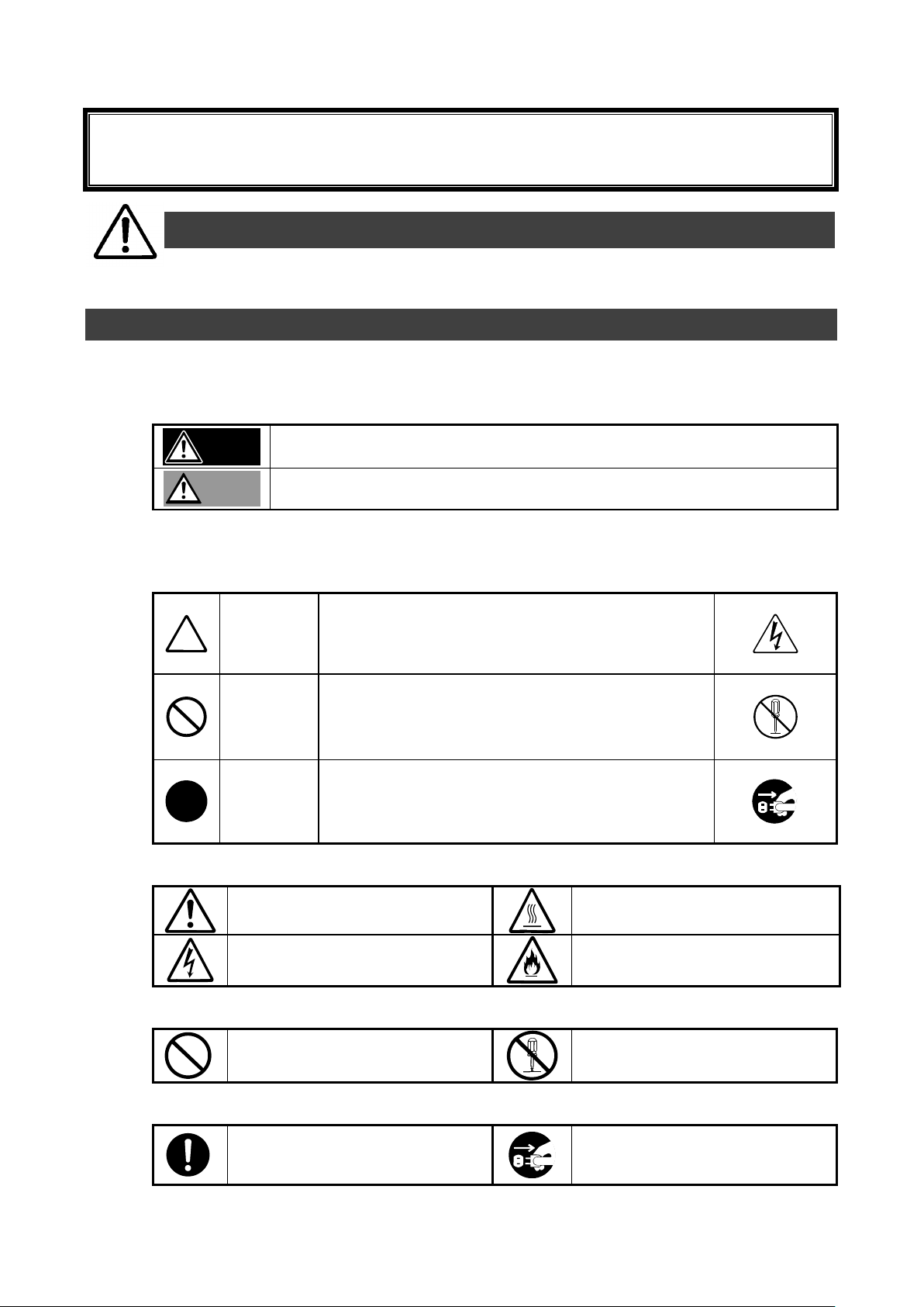
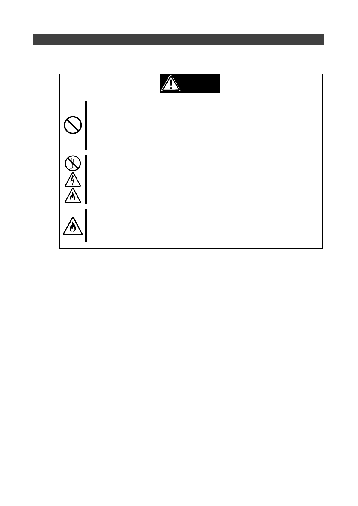
警告
人が死亡する、または重傷を負うおそれがあることを示します。
注意
火傷や怪我などを負うおそれや物的損害を負うおそれがあることを示します。
注意の喚起
この記号は危険が発生するおそれがあることを表します。記号
の中の絵表示は危険の内容を図案化したものです。
(例)
(感電注意)
行為の禁止
この記号は行為の禁止を表します。記号の中や近くの絵表示
は、してはならない行為の内容を図案化したものです。
(例)
(分解禁止)
行為の強制
この記号は行為の強制を表します。記号の中の絵表示は、しな
ければならない行為の内容を図案化したものです。危険を避け
るためにはこの行為が必要です。
(例)
(コードを抜け)
特定しない一般的な注意・警告を示しま
す。
高温による傷害を負うおそれがあること
を示します。
感電のおそれがあることを示します。
発煙または発火のおそれがあることを示
します。
特定しない一般的な禁止を示します。
本装置を分解・修理・改造しないでくだ
さい。感電や火災のおそれがあります。
特定しない一般的な使用者の行為を指示
します。説明に従った操作をしてくださ
い。
本装置の電源コー ドをコ ンセントから
抜いてください。火災や感電のおそれが
あります。
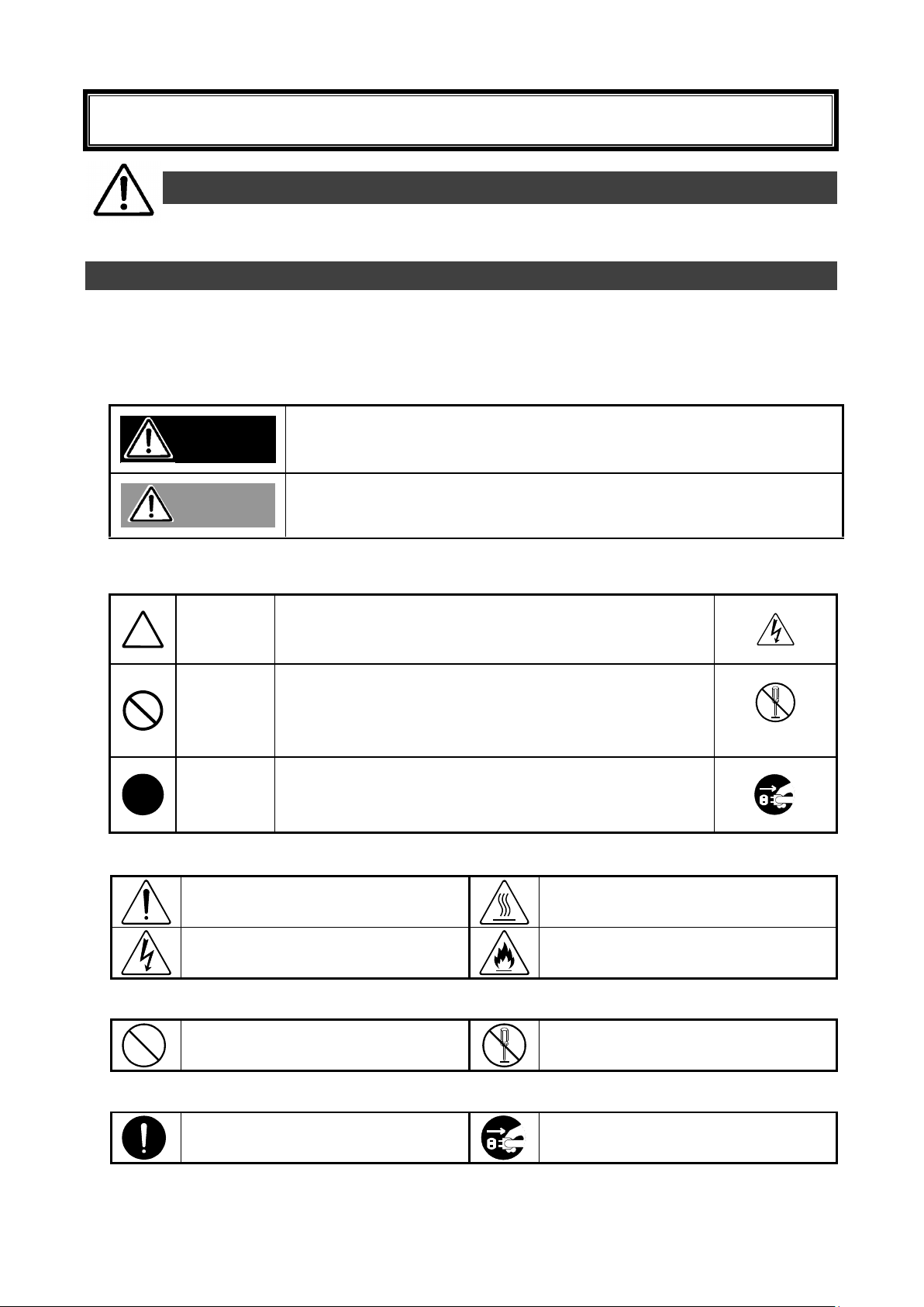
安全上のご注意 ~ 必ずお読みください ~
本製品を安全に正しくご使用になるために必要な情報が記載されています。
安全にかかわる表示
本書では危険の程度を表す言葉として、「警告」と「注意」という用語を使用しています。それぞれの
用語は次のような意味を持つものとして定義されています。
表示は次の3種類の記号を使って表します。それぞれの記号は次のような意味を持つものものとし
て定義されています。
注意の喚起
行為の禁止
行為の強制
- 1 -
Page 4
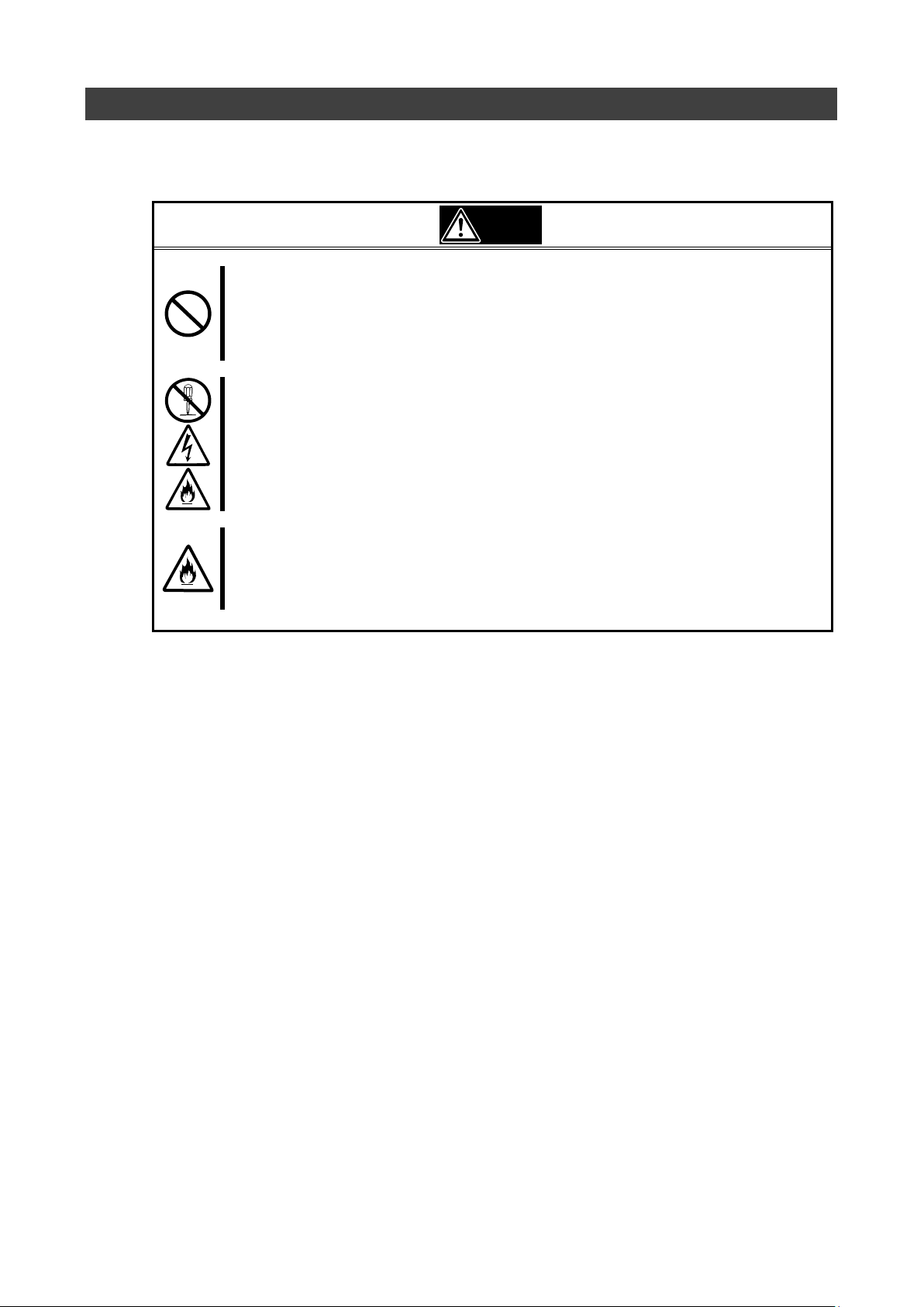
警告
人命に関わる業務や高度な信頼性を必要とする業務には使用しない
本製品は、医療機器、原子力設備や機器、航空宇宙機器、輸送設備や機器など、人命に関わる設
備や機器および高度な信頼性を必要とする設備や機器などへの組み込みやこれら機器の制御な
どを目的とした使用は意図されておりません。これら設備や機器、制御システムなどに本製品を
使用した結果、人身事故、財産損傷などが生じても当社はいかなる責任も負いかねます。
ご自分で分解、修理、改造はしない
本書に記載されている場合を除き、絶対に分解したり、修理・改造を行ったりしないでください。
装置が正常に動作しなくなるばかりでなく、感電や火災の危険があります。故障の際はお買い求
めの販売店または保守サービス会社にご連絡ください。
煙や異臭・異音がしたまま使用しない
万一、煙・異臭・異音などが生じた場合は、ただちに電源を OFF にして電源コードをコンセント
から抜いてください。その後、お買い求めの販売店または保守サービス会社にご連絡ください。
そのまま使用すると火災の原因となります。
安全上のご注意
本製品を安全にお使いいただくために、ここで説明する注意事項をよく読んでご理解し、安全にご
活用ください、記号の説明については巻頭の「安全にかかわる表示」の説明をご参照ください。
<次頁に続く>
- 2 -
Page 5
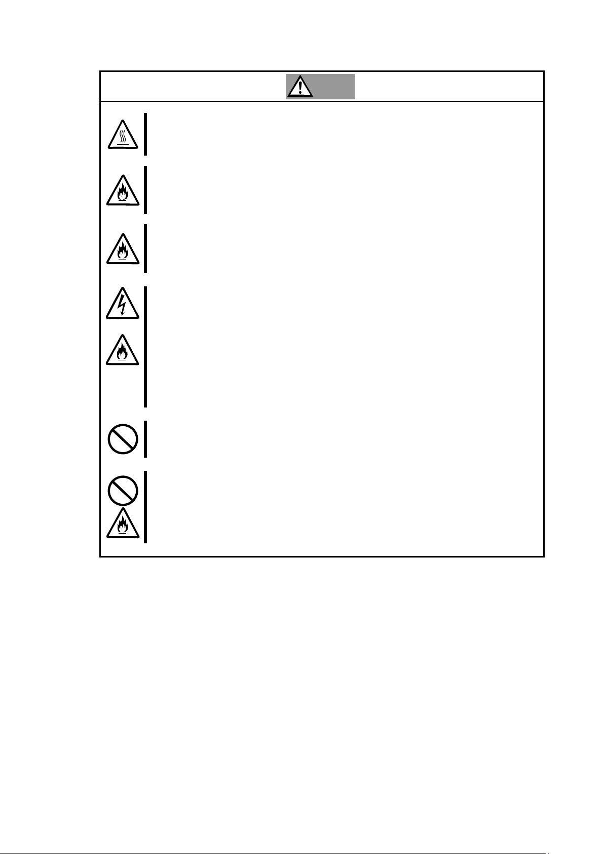
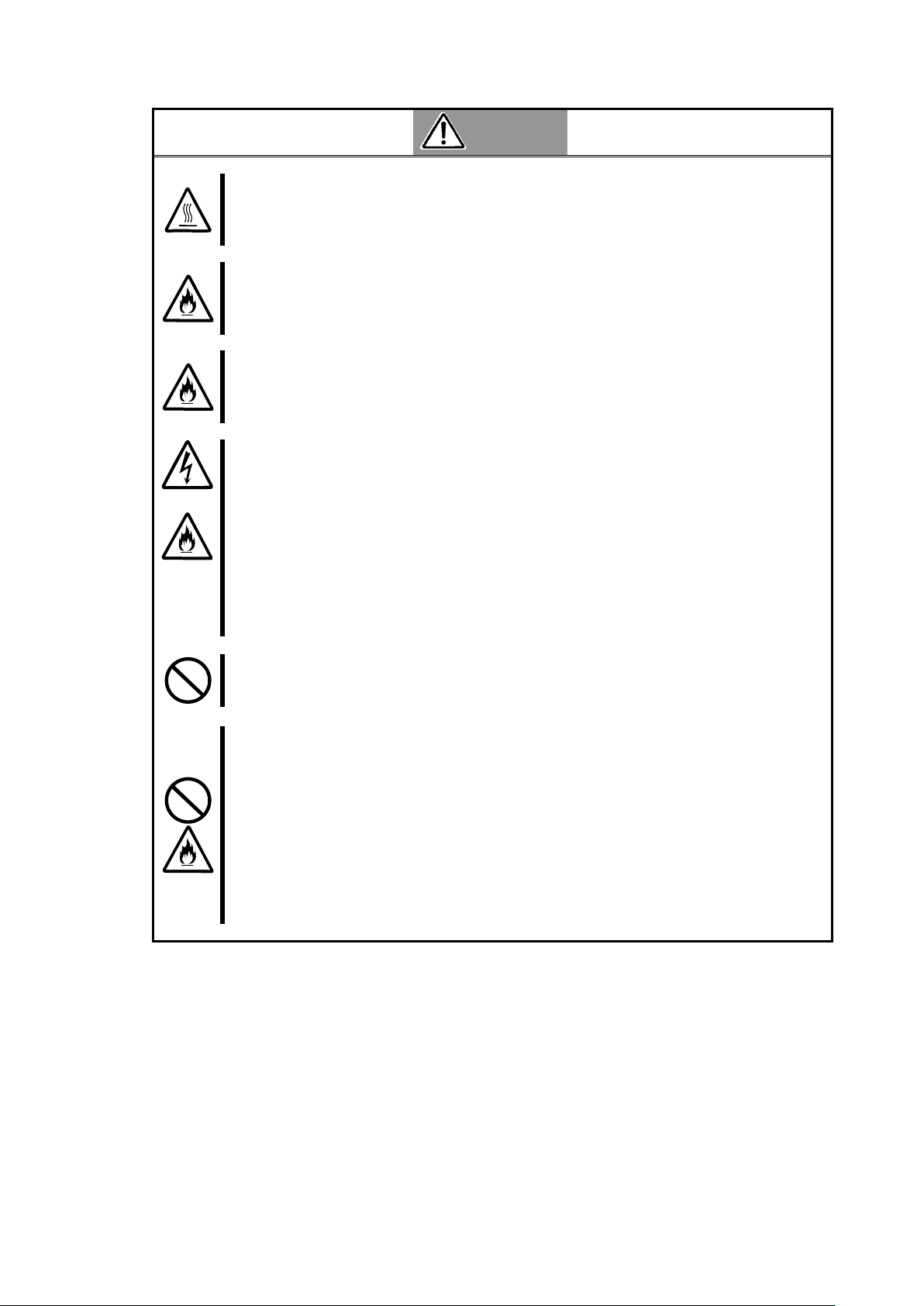
注意
高温に注意する
CPU ブレードの電源を OFF にした直後は、装置内の部品が高温になっています。十分に冷めたこ
とを確認してから取り付け/取り外しを行ってください。
確実に接続する
本製品を CPU ブレードのメザニンスロットに接続するときは、確実に差し込んでネジを締めてく
ださい。完全に差し込まなかったり、ネジを締めなかった場合、発煙や発火のおそれがあります。
中途半端に差し込まない
電源コードおよびケーブルは根本までしっかりと差し込んでください。中途半端に差し込むと接
触不良のため発熱し、火災の原因となることがあります。また差し込み部にほこりがたまり、水
滴などが付くと発熱し、火災の原因となるおそれがあります。
指定以外のインターフェースケーブルを使用しない
インターフェースケーブルは、指定するものを使用し、接続する装置やコネクタを確認した上で
接続してください。指定以外のケーブルを使用したり、接続先を誤ったりすると、ショートによ
り感電や火災を起こすことがあります。
インターフェースケーブルの取り扱いや接続について次の注意をお守りください。
・破損したケーブルを使用しない。
・ケーブルを踏まない
・ケーブルの上にものを載せない
・ケーブルを改造・加工・修復しない
携帯電話などを近くで使用しない
携帯電話やPHS、ポケットベルなどを近くで使用しないでください。電波による誤動作の原因
となります。
腐食性ガスの存在する環境で使用または保管しない
腐食性ガス(二酸化硫黄、硫化水素、二酸化窒素、塩素、アンモニア、オゾンなど)の存在する
環境に設置し、使用しないでください。また、ほこりや空気中に腐食を促進する成分(塩化ナト
リウムや硫黄など)や導電性の金属などが含まれている環境へも設置しないでください。装置内
部のプリント板が腐食し、故障および発煙・発火の原因となるおそれがあります。もしご使用の
環境で上記の疑いがある場合は、販売店または保守サービス会社にご相談ください。
- 3 -
Page 6
Keep this manual handy for quick reference when necessary. Be sure to read the "Safety
Precautions" and "Precautions on Use."
Indicates a hazard that can lead to death or serious injury.
Indicates a hazard that can lead to burns, injury, or damage to property .
Attention
This symbol indicates the presence of a hazard. An image in the
symbol illustrates the hazard type.
(Example)
(Electric shock)
Prohibited
Action
This symbol indicates prohibited actions. An image in the symbol
illustrates a particular prohibited action.
(Example)
(Do not
disassemble)
Mandatory
Action
This symbol indicates mandatory actions. An image in the symbol
illustrates a mandatory action to avoid a particular hazard.
(Example)
(Unplug)
Indicates general warnings and
cautions.
Indicates a hazard that can lead to
burns.
Indicates a hazard that can lead to
electric shock.
Indicates a hazard that can lead to fire.
Indicates a general prohibition.
Indicates prohibition of disassembly or
modification.
Indicates a general instruction for users.
Indicates that you must unplug from the
electrical outlet.
CAUTION
WARNING
Safety Precautions - Read carefully -
The following includes information necessary for proper and safe operation of the product.
Safety Symbols
Follow all instructions in this User's Guide to ensure the safe operation of this controller This guide
explains what areas pose a danger, what may result from not following safety instructions, and how
to avoid danger. "Warning" and "Caution" are the terms used to express the level of danger.
These terms mean the following:
Precautions and notices against hazards are presented with one of the following three symbols.
The individual symbols are defined as follows:
Attention
Prohibited Action
Mandatory Action
- 4 -
Page 7
Do not use this product for services where critical high availability may
directly affect human lives.
This product is not intended to be used with or control facilities or devices concerning
human lives, including medical devices, nuclear facilities and devices, aeronautics and
space devices, transportation facilities and devices; and facilities and devices requiring
high reliability. NEC assumes no liability for any accident resulting in personal injury,
death, or property damage if this product has been used in the above conditions.
Do not disassemble, repair, or alter this product.
Never attempt to disassemble, repair, or alter this product on any occasion other than
described in this manual. Failure to follow this instruction may cause an electric shock
or fire as well as malfunctions of this product.
Do not use this product if any smoke, odor, or noise is present.
If smoke, odor, or noise is present, immediately turn off the POWER/SLEEP switch
and disconnect the power plug from the outlet, then contact your sales agent. Using
this product in such conditions may cause a fire.
WARNING
Safety Precautions
Please read and make sure you understand the warnings and cautions described below to use the
product safely. Please refer to "Safety Symbols" at the beginning for an explanation on the symbols.
<Continued on next page.>
- 5 -
Page 8
Avoid installation in extreme temperature conditions.
Immediately after the server is powered off, its internal components such as hard disks
are very hot. Leave the server until its internal components fully cool down before
installing/removing any component.
Connect firmly.
Please connect the product to the computer firmly. A loose connection can cause a
contact failure and can lead to smoke or fire.
Insert the power plug into the outlet as far as it goes.
Heat generation resulting from a halfway inserted power plug/cable (imperfect contact)
may cause a fire. Heat will also be generated if condensation is formed on dusty
blades of the halfway inserted plug, increasing the possibility of fire.
Do not use an unauthorized interface cable.
Use only the interface cable that comes with this product. Use of an unauthorized
interface cable may cause a fire when the electric current exceeds the rated flow.
Also, observe the following to prevent an electric shock or fire caused by a damaged
cord:
Do not use a damaged cable. (Replace a damaged cable with a new one of the
same specifications. Ask your sales agent for replacement.)
Do not step on the cable.
Do not place any object on the cable.
Do not alter, modify, or repair the cable.
Do not use a cellular phone or pager around this product.
Turn off cellular phones or pagers. Radio interference may cause malfunctions of this product.
Do not use or store this product in a corrosive environment.
Avoid the usage or storage of this product in an environment which may be exposed to
corrosive gases, such as those including but not limited to: sulfur dioxide, hydrogen sulfide,
nitrogen dioxide, chlorine, ammonia and/or ozone.
Avoid installing this product in a dusty environment or one that may be exposed to corrosive
materials such as sodium chloride and/or sulfur.
Avoid installing this product in an environment which may have excessive metal flakes or
conductive particles in the air.
Such environments may cause corrosion or short circuits within this product, resulting in not only
damage to this product, but also posing a fire hazard.
If there are any concerns regarding the environment at the planned site of installation or
storage, please contact your sales agent.
CAUTION
- 6 -
Page 9

使用上のご注意 ~本製品を正しく動作させるために~
本製品を使用するときに注意していただきたいことを次に示します。これらの注意を無視して、本
製品を使用した場合、資産(データやその他の装置)が破壊されるおそれがありますので必ずお守り
ください。
本製品は大変静電気に弱い電子部品です。ブレード収納ユニットの金属フレーム部分などに触
れて身体の静電気を逃がしてから取り扱ってください。また、本製品の端子部分や部品を素手
で触ったり、直接机の上に置いたりしないでください。
本製品を落としたり物にぶつけたりしないでください、誤動作や故障するおそれがあります。
本書及び CPU ブレードのユーザーズガイドに記載されている説明をよくお読みになり、正しく
取り扱ってください。
CPU ブレードのメザニン拡張スロットにうまく本製品を取り付けられないときは、いったん本
製品を取り外してから取り付けなおしてください。過度の力を加えると破損するおそれがあり
ますので注意してください。
Precautions on Use - Operating this product properly -
The following precautions must be observed when using this controller. Ignoring these precautions while
using this controller will result in the destruction of assets (data and other devices).
Please observe the following:
This product is sensitive to static electricity. Please discharge any static electricity by touching a metal
object such as the metal frame of the Enclosure before handling the product. Also, do not touch the
contacts of the product or place the product on a desk.
Do not drop or hit the product. Doing so can lead to malfunction or failure.
Please read this manual and the CPU Blade manual and handle the product correctly.
Please read the user's manual of the CPU Blade before installing this product. When installing the
product, insert the product firmly into the Mezzanine slot. If this product is not correctly connected to the
Mezzanine slot of the CPU Blade, remove the product and install it again. Using excessive force can
lead to damage.
- 7 -
Page 10
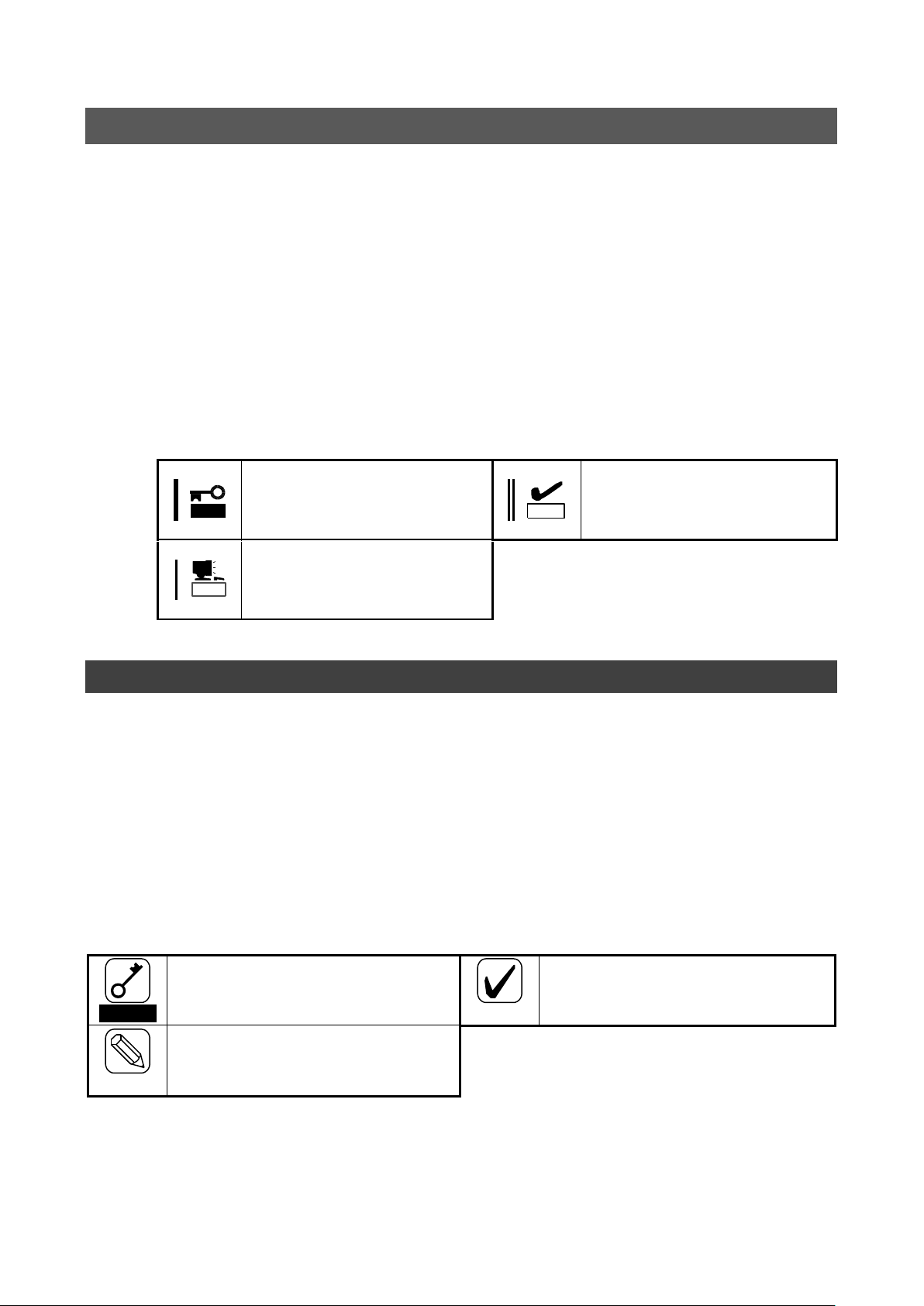
本製品を取り扱う上で守らなけれ
ばならない事柄や特に注意すべき
点を示します。
本製品を取り扱う上で確認してお
く必要がある点を示します。
重要
チェック
知っておくと役に立つ情報や、便
利なことなどを示します。
ヒント
Important
Indicates important instructions and
cautions on handling this product.
Check
Indicates information that needs to be
confirmed before handling this product.
Hint
Indicates useful information on using
this product.
本書について
本書は、N8403-018 Fibre Channel コントローラを正しくセットアップし、使用できるようにするための手
引きです。本製品を使用される前に本書をよくお読みになり、いつでも取り出せる場所に大切に保管してく
ださい。本製品の移設の際は必ず本書も一緒に移設してください。
本書は、Windows などのオペレーティングシステムやキーボード、マウスといった一般的な入
出力装置などの基本的な取り扱いについて十分な知識を持ったユーザを対象として記載され
ています。
本文中の記号
本文中では次の 3 つの記号を使用しています。それぞれの意味を示します。(「安全にかかわる表示」
については 1 ページをご参照ください)
About This Manual
This manual explains how to set up and use the N8403-018 Fibre Channel Controller correctly. Be sure to
read this manual before using the product and keep it in a safe place after reading it. If the product is
transferred to a third party, please transfer this manual along with it.
This manual is written for users with sufficient knowledge of operating systems such as
Windows Server 2003, a keyboard and mouse, and general I/O devices.
Symbols Used in This Manual
The following three symbols are used in this manual. The meanings of the symbols are described below. (For
information on safety, please refer to the section "Safety Symbols.")
- 8 -
Page 11

重要
ハードディスクドライブやバックアップデータカートリッジ、フロッピーディスク、その
他書き込み可能なメディア(CD-R/CD-RWなど)に保存されているデータは、第三
者によって復元や再生、再利用されないようお客様の責任において確実に処分してから廃
棄してください。個人のプライバシーや企業の機密情報を保護するために十分な配慮が必
要です。
梱包箱の中身について
梱包箱の中には本製品以外に色々な部品が入っています。「第2章 構成品」を参照し、全ての添付品がそろ
っていることを確認してください。万一、足りないものや破損しているものがあった場合には、本製品をご
購入された販売店にご連絡ください。
保証について
本製品には「保証書」が添付されています。「保証書」は販売店で所定事項を記入しお渡ししますので、記載
内容をご確認の上、大切に保管してください。保証期間中に故障した場合には、「保証書」の記載内容に基づ
き無償修理致します。保証後の修理については、ご購入された販売店もしくはご契約されている保守サービ
ス会社にご相談ください。
製品寿命について
本製品の製品寿命は5年です。本製品の交換については、本製品をご購入された販売店もしくはご契約され
ている保守サービス会社へご相談ください。
第三者への譲渡について
本製品を第三者に譲渡(または売却)する時には、必ず本書を含む全ての添付品をあわせて譲渡(または売
却)してください。
ソフトウェアに関しては、譲渡した側は一切の複製物を所有しないでください。また、インストールした装
置から削除した後、譲渡してください。
輸送について
本製品を輸送する際は、「第2章 構成品」を参考に CPU ブレードから本製品を取り外し、本製品とすべての
添付品を購入時の梱包箱に入れてください。
データの保管について
オペレータの操作ミス、衝撃や温度変化等による装置の故障によってデータが失われる可能性があります。
万一に備えて、ハードディスクドライブに保存されている大切なデータは、定期的にバックアップを行って
ください。
廃棄について
本製品の廃棄については、各自治体の廃棄ルールに従って分別廃棄してください。詳しくは、各自治体にお
問い合わせください。
- 9 -
Page 12

Important
Securely erasing the data saved on hard disks, backup data cartridges, floppy
disks, and other media (such as CD-R and CD-RW discs) is the customer’s
responsibility. To ensure that the data may not be restored, reproduced, and/or
reused by third parties, take sufficient measures to protect personal privacy and
corporate information.
Packing Box Contents
There are other accessories included in the packing box besides this controller. Please refer to the packing
list in the box to make sure that all parts are included. Contact the dealer that you bought this controller from
if any parts are missing or damaged.
Lifetime
This product has a product lifetime of five years.
The holding period for replacement parts is five years from production.
Transferring Ownership to a Third Party
When transferring ownership or selling this product to a third party, be sure to pass on this manual and all
accessories together with this product.
The party transferring or selling this controller must transfer all software and maintain no copies. Also, all
installed software must be deleted before this product is transferred or sold.
Transportation
When transporting this product, please refer to "2.Components" to remove this controller from the CPU blade
and repack it and all of its accessories into the original packing box.
Storing Data
Data may be lost through a device malfunction due to human error, physical shock, temperature change, or
other means. To prevent this, be sure to regularly backup essential data saved on the hard disk.
Disposal
Dispose of this product according to governing regulations. Contact your local government for details.
- 10 -
Page 13

目次
安全上のご注意 ~ 必ずお読みください ~ ....................................................................... 1
安全にかかわる表示 .............................................................................................................................. 1
安全上のご注意 ..................................................................................................................................... 2
Safety Precautions - Read carefully - ................................ ................................ ............ 4
Safety Symbols .................................................................................................................................... 4
Safety Precautions .............................................................................................................................. 5
使用上のご注意 ~本製品を正しく動作させるために~ .................................................................... 7
Precautions on Use - Operating this product properly -................................................................. 7
本書について ......................................................................................................................................... 8
本文中の記号 ......................................................................................................................................... 8
About This Manual .............................................................................................................................. 8
Symbols Used in This Manual ........................................................................................................... 8
梱包箱の中身について .......................................................................................................................... 9
保証について ......................................................................................................................................... 9
製品寿命について .................................................................................................................................. 9
第三者への譲渡について ....................................................................................................................... 9
輸送について ......................................................................................................................................... 9
データの保管について .......................................................................................................................... 9
廃棄について ......................................................................................................................................... 9
Packing Box Contents ...................................................................................................................... 10
Lifetime ............................................................................................................................................... 10
Transferring Ownership to a Third Party ........................................................................................ 10
Transportation.................................................................................................................................... 10
Storing Data ....................................................................................................................................... 10
Disposal .............................................................................................................................................. 10
目次 .......................................................................................................................................................11
Contents ............................................................................................................................................. 12
1.本製品について ............................................................................................................... 13
1-1.仕様 ............................................................................................................................................... 13
1-2.本製品の特徴 ................................................................................................................................. 13
2.構成品 ............................................................................................................................. 14
3.各部の名称と機能 ........................................................................................................... 14
4.セットアップ手順 ........................................................................................................... 16
4-1.本製品の取り付け ......................................................................................................................... 17
4-2.WWPN ラベルの貼り付け ............................................................................................................. 18
4-3.CPU ブレードの取り付け ............................................................................................................. 18
4-4.ドライバのインストール............................................................................................................... 18
5.注意事項/困ったときの処理 ............................................................................................ 19
5-1.困ったときの処理 ......................................................................................................................... 19
付録 Fibre Channel 装置からの起動 ................................................................................ 22
事前準備 .............................................................................................................................................. 22
BIOS 設定変更..................................................................................................................................... 23
- 11 -
Page 14

Contents
1. About This Product ...................................................................................................... 28
1-1. Specifications ............................................................................................................................. 28
1-2. Features ...................................................................................................................................... 28
2. Components ................................................................................................................. 29
3. Names and Functions .................................................................................................. 29
4. Setup ............................................................................................................................. 31
4-1. Install the Card ........................................................................................................................... 32
4-2. Label WWPN address ................................................................................................................ 33
4-3. Install the CPU Blade ................................................................................................................. 33
4-4. Installing the Driver .................................................................................................................... 33
5. Troubleshooting ........................................................................................................... 34
5-1. Troubleshooting ......................................................................................................................... 34
Appendix Boot from Fibre Channel device ................................................................... 36
Preparations ....................................................................................................................................... 36
Change BIOS settings ....................................................................................................................... 37
- 12 -
Page 15

項目
仕様
備考
Fibre Channel インターフェース
なし(外部ポート×2)
Fibre Channel 機器の接続に
は FC スルーカードもしくは
FC スイッチモジュールが必
要になります。
Fibre Channel 速度
4Gbps,2Gbps
ポート数
2
形態
ブレード用タイプ1
メザニンカード
タイプ 1 もしくはタイプ 2 の
メザニン拡張ス ロ ッ ト に実
装可能です。
外形寸法
115mm(幅)×100mm(奥行)
重量
0.1kg 以下
動作電圧
3.3V
消費電力
定常 4.55W
最大 6.5W
動作環境
動作時
温度 0 ~ 45℃
湿度 5 ~ 95%
結露しないこと
保管時
温度-40 ~ 70℃
湿度 5 ~ 95%
重要
弊社が指定する CPU ブレード及び Fibre Channel 機器以外は接続しないでください。
指定以外の CPU ブレード及び Fibre Channel 機器に接続できたとしても本製品及び
接続した Fibre Channel 機器が正常に動作しないばかりか、故障するおそれがあり
ます。
接続可能な CPU ブレード及び Fibre Channel 機器については、本製品を購入された
販売店または保守サービス会社にお問い合わせください。
Fibre Channel 機器を接続するには別途 FC スルーカードもしくは FC スイッチモジ
ュールが必要になります。
1.本製品について
1-1.仕様
1-2.本製品の特徴
N8403-018 Fibre Channel コントローラは、Express5800/BladeServer シリーズ専用の拡張用メザニ
ンカードです。本製品によって Fibre Channel 機器を制御することができます。
- 13 -
Page 16

(2)IEEE アドレス(ポート 0)
(3) メザニンコネクタ
(2)IEEE アドレス(ポート 1)
2.構成品
梱包箱にはコントローラボード以外に付属品が入っています。添付の構成品表を参照し全てそろって
いることを確認してください。万一、足りないものや破損しているものがありましたら、販売店にご
連絡ください。
3.各部の名称と機能
- 14 -
Page 17

ヒント
IEEE アドレスの値は本製品の WorldWideName(WWN)の下12桁と一致し
ます
ヒント
本製品はメザニンタイプ 1 もしくは タイプ 2 の拡張スロットに実装可能で
す。
(1) 固定ネジ
CPU ブレードのスペーサーへ固定するためのネジ。
(2) IEEE アドレス(ポート 0/ポート 1)
本製品の IEEE アドレスが表示されています。
(3) メザニンコネクタ
CPU ブレード内部のメザニン拡張スロットと接続する端子。
- 15 -
Page 18

「ユーザーズガイド(本書)」
の説明範囲
本製品の取り付け
→17ページ
CPU ブレードに本製品を取り付けます。
WWPN ラベルの貼り付け
→18ページ
ブレード管理シートに WWPN ラベルを貼り付けます。
CPU ブレードの取り付け
→18ページ
CPU ブレードをブレード収納ユニットに取り付けます。
「CPU ブレード付属ユーザ
ーズガイド」の説明範囲
ドライバのインストール
→「CPU ブレード付属ユーザーズガイド」
参照
使用するオペレーティングシステム用のドライバをインストールします。
4.セットアップ手順
次の手順に従って本製品のセットアップを行います。
- 16 -
Page 19
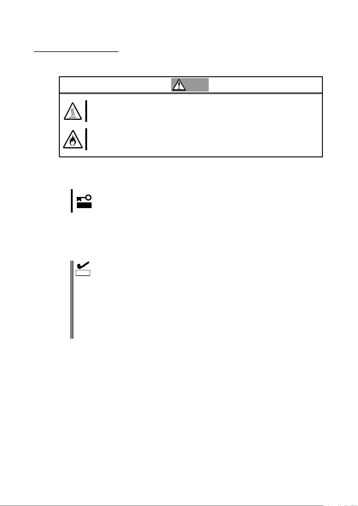
注意
高温に注意する
CPU ブレードの電源を OFF にした直後は、装置内の部品が高温になっています。十分に冷めたこ
とを確認してから取り付け/取り外しを行ってください。
確実に接続する
CPU ブレードに取り付ける際は確実に接続してください。中途半端に取り付けると接触不良を起
こし、発煙や発火の原因となるおそれがあります。
重要
CPU ブレードの電源が ON(POWER ランプ点灯)になっている場合は、各オペレー
ティングシステムの電源 OFF の処理を行った後、CPU ブレードの電源を OFF に
してください。
チェック
本製品の取り付け・取り外し方法は CPU ブレードにより異なりますので必ず CPU
ブレードの説明書をお読みください。
CPU ブレードに本製品を取り付けられないときは、いったん本製品を取り外し
てから取り付けなおしてください。過度の力を加えると破損するおそれがあり
ますので注意してください。
FC スルーカードもしくは FC スイッチモジュールの実装箇所に対応したメザニ
ン拡張スロットに本製品を実装してください。それぞれの実装箇所が対応して
いないと、Fibre Chanel 機器に接続することが出来ません。詳細についてはブ
レード収納ユニット、FC スルーカードもしくは FC スイッチモジュールの説明
書をお読みください。
4-1.本製品の取り付け
次に示す手順に従って本製品を CPU ブレードに取り付けます。
1. 本製品を取り付ける CPU ブレードの電源が OFF(POWER ランプ消灯)になっていることを確認し
ます。
2. CPU ブレードの説明書に従ってブレード収納ユニットから本製品を取り付ける CPU ブレードを
取り出します。
3. CPU ブレードの説明書に従って本製品をメザニンスロットに取り付けます。
4. 固定用ネジを締めて本製品を CPU ブレードに固定します。
- 17 -
Page 20

重要
WWPN ラベルを貼り付けるときに、貼り付ける本製品の IEEE アドレスと WWPN
ラベルの下 12 桁の表示が一致していることを確認してください。
ヒント
WWPN ラベルをブレード管理シートに貼り付けることにより、外部から WWPN
を確認可能となります。
注意
高温に注意する
CPU ブレードの電源を OFF にした直後は、装置内の部品が高温になっています。十分に冷めたこ
とを確認してから取り付け/取り外しを行ってください。
確実に接続する
CPU ブレードを取り付ける際は確実に接続してください。中途半端に取り付けると接触不良を起
こし、発煙や発火の原因となるおそれがあります。
CPU Blade
SLOT #
Model Name
: N8400-
No. :
FR :
MAC Address Label
LAN 1 :
LAN 2 :
Option Card Label
HDD
ID:0
ID:1
Option Card Label
WWPN ラベル
上段の P0 以降が Port0、下段の P1 以降が Port1
の WorldWidePortName(WWPN)となります
P0 10-00-00-00-C9-5B-00-00
N8403-018
4-2.WWPN ラベルの貼り付け
本製品を実装する箇所のブレード管理シートに N コード「N8403-018」を記入して、本製品付属の
WWPN ラベルを貼り付けてください。
4-3.CPU ブレードの取り付け
CPU ブレードの説明書に従ってブレード収納ユニットに CPU ブレードに取り付けます。
4-4.ドライバのインストール
本製品をご使用いただくには、各オペレーティングシステムに対応する Fibre Channel ドライバを
インストールする必要があります。詳しくは、CPU ブレードに付属の説明書を参照してください。
- 18 -
Page 21

重要
以上の確認を行っても本体装置起動中にエラーメッセージが表示される場合は、い
ったん本製品を別のメザニンスロットに取り付けた後、本体装置を起動して自己診
断プログラム「POST」の実行で異常がないことを確認してください。POST が正常に終
了するようでしたら、本体装置が故障していることが考えられます。本体装置を購
入された販売店または保守サービス会社にご連絡ください。
5.注意事項/困ったときの処理
本製品をご使用される際の注意事項及び困ったときの処理について、下記に記します。
該当する項目がある場合は、説明に従って正しく対処してください。
5-1.困ったときの処理
本体装置起動中にエラーメッセージが表示される
本体装置に添付のマニュアルを参照してエラーメッセージの内容を確認してください。
本製品が取り付けられているスロットに原因があると思われるときは、次の点について確認および対処
をしてください。
● Option ROM が展開できていない場合
→ 本体装置に添付のマニュアルを参照して、使用していない機能もしくは本製品が搭載されてい
るメザニンスロットの Option Rom を無効にしてください。
● 本製品を取り付けたメザニンスロットで異常が発生している場合
→ もう一度しっかりと本製品を接続し直してください。
本製品が正常に動作しないとき
本製品を取り付けた後、OS やアプリケーションが正常に動作しなかったときは、次の点について確認
および対処してください。また、CPU ブレードに添付のマニュアルもあわせて参照してください。
● Fibre Channel ドライバをお使いになっている CPU ブレードにインストールしていますか?
また、正しくセットアップしましたか?
→ CPU ブレードに添付のマニュアルを参照してください。
● 本製品やケーブルはしっかり接続されていますか?
→ もう一度しっかりと接続し直してください。
● WWPN を利用する Fibre Channel 装置を接続している場合、間違った WWPN を設定していませんか?
→ WWPN ラベル/IEEE アドレスから番号が間違っていないか確認してください。
● FC スルーカード、FC スイッチモジュールの FC 速度やトポロジが FC デバイスに対応していますか?
→ FC スルーカード、FC スイッチモジュール、接続している FC デバイスのマニュアルを確認して
ください。
● 本製品を実装したメザニン拡張スロット、CPU ブレードを実装したスロットの位置、FC スルーカー
ドもしくは FC スイッチモジュール、SFP モジュールを実装した位置は対応が取れていますか?
→ CPU ブレード、ブレード収納ユニット、FC スルーカードもしくは FC スイッチモジュールの説
明書を参照してください。
- 19 -
Page 22

重要
以上の確認を行っても CPU ブレードが正しく動作しない場合は、いったん本製品を
取り外した後、CPU ブレードを起動して自己診断プログラム「POST」の実行で異常が
ないことを確認してください。POST が正常に終了するようでしたら、本製品が故障
していることが考えられます。本製品を購入された販売店または保守サービス会社
にご連絡ください。
- 20 -
Page 23

重要
以上の確認を行っても Fibre Channel 機器が認識できない場合は、本製品を購入さ
れた販売店または保守サービス会社にご連絡ください。
Fibre Channel 機器が認識できなくなったとき
本製品に接続してご使用になっていた Fibre Channel 機器が、CPU ブレードの起動後、OS から正常に認
識されなくなった、またはアクセスできなくなった場合は、次の点について確認および対処してくださ
い。また、Fibre Channel 機器に添付のマニュアルやご使用になっているアプリケーションのマニュア
ルもあわせて参照してください。
<Windows2003 server の場合>
● [コントロールパネル]-[管理ツール]-[コンピュータの管理]-[デバイスマネージャ]を選択し、[ディスクドライブ]
配下に Fibre Channel 機器が表示されていますか?
→ 表示されていない場合は、以下の2通りの対処方法が考えられます。
(1) [コンピュータの管理]-[ディスクの管理]を起動して、正常に Fibre Channel 機器のデバイス
に割り付けたドライブ文字が認識できるようであれば、コンピュータの管理を終了後、再度ア
クセスを行ってください。
(2)CPU ブレードをリブート可能であれば、リブート後アクセスを行ってください。
<各 OS 共通>
● FC スルーカード、FC スイッチモジュールの FC 速度やトポロジが FC デバイスに対応していますか?
→ FC スルーカード、FC スイッチモジュール、接続している FC デバイスのマニュアルを確認して
ください。
● 接続する Fibre Channel 機器は正常に動作・起動していますか?
→ 各機器に添付された説明書を参照の上、正常に動作・起動している事を確認してください。
- 21 -
Page 24

重要
本製品から接続した Fibre Channel 装置に OS をインストールしない場合は BIOS 設
定の変更を行わないでください。
サポートしている OS と Fibre Channel 装置の組み合わせ以外で OS インストールを
行わないでください。サポートしている OS と Fibre Channel 装置の組み合わせに
ついては本製品を購入された販売店または保守サービス会社にお問い合わせくだ
さい。
ヒント
BIOS 設定を変更する際にディスプレイとキーボードが必要になります。
重要
内蔵ディスクが接続されているとデバイスの認識順番によりシステムが起動しな
い等のトラブルが発生することがあります。
重要
OS をインストールする LUN(Logical Unit Number)は「0」である必要があります。
重要
BIOS 設定変更時には誤って設定してしまうことを防ぐ為、OS インストールの際に
は Fibre Channel 機器を 1 系統のみ接続するようにしてください。
付録 Fibre Channel 装置からの起動
本製品から接続した Fibre Channel 装置に OS をインストールして起動することが出来ます。
この場合は本製品の BIOS 設定の変更が必要になりますので、説明に従って正しく設定を行ってください。
事前準備
本製品を取り付ける CPU ブレード、インストールを行う Fibre Channel 装置に対して以下の準備を
行ってください。
<CPU ブレード>
キーボード、ディスプレイを対象の CPU ブレードに接続してください。
Fibre Channel 装置から起動を行う CPU ブレードに対して内蔵ディスクが接続されていないこ
とを確認してください。
<Fibre Channel 装置>
事前にインストールを行う Fibre Channel 装置に LUN 0 のディスク領域を構成し、本製品から
認識できる状態にしておいてください。
本製品のコネクタとインストールを行う Fibre Channel 装置のコネクタを接続してください。
- 22 -
Page 25
ヒント
ロゴが表示され、BIOS 画面が表示されない場合には、<ESC>を押すことでBIOS
画面が表示されます。
!!! LPe1105-N BIOS, Copyright (c) 2005 Emulex !!! Version 1.70a3
Press <Alt E> To Go To Emulex BIOS Utility
Press <S> To Skip Emulex BIOS
重要
本製品の BIOS 設定画面を表示させるとメモリを使用します。従って、お使いの環
境によっては、上記画面が表示されない場合や設定が行えない場合があります。こ
の場合は CPU ブレードで不要な拡張 ROM を Disable にするなどの処置を実施してく
ださい。拡張 ROM を Disable にする方法は、CPU ブレードに付属の説明書を参照し
てください
Bring the Link up, Please wait…
Bring the Link up, Please wait…
Emulex Light Pulse BIOS Utility, ZB1.70A3
Copyright (c) 2005 Emulex Design & Manufacturing Corp.
Emulex Adapters in the System:
1. LPe1105-N: PCI Bus #:07 PCI Device #:00
2. LPe1105-N: PCI Bus #:07 PCI Device #:00
Enter a Selection: _
Enter <x> to Exit
ヒント
上記のメニューが表示されずに先に進んでしまった場合は<Alt>と<Ctrl>と
<Del>を同時に押して、CPU ブレードを再起動させてやり直してください。
表示内容は一例であり、CPU ブレードや構成によって一部異なる可能性があ
ります。
BIOS 設定変更
事前準備が完了しましたら以下の手順に従い、本製品の BIOS 設定変更(Boot デバイス登録、Boot BIOS
有効化)を実施してください。
1> Fiber Channel 装置との接続・状態を確認し、CPU ブレードの電源をオンにしてください。
2> 下記メッセージが表示されている時に、<Alt>と<E>を同時に押して、本製品の BIOS メニューを表示
させてください。
3> <Alt>と<E>を押したことが認識されると以下のメッセージが表示され、メニューが表示されます。
- 23 -
Page 26

Adapter 01: PCI Bus #:07 PCI Device #:00
LPe1105-N I/O Base: 4000 Firmware Version: ZS2.50A8
Port Name: 10000000 C92B6B74 Node Name: 20000000 C92B6B74
Topology: Auto Topology: Loop first (Default)
1. Configure Boot Devices
2. Configure This Adapter's Parameters
Enter a Selection: _
Enter <x> to Exit <d> to Default Values <Esc> to Previous Menu
Adapter 01: S_ID:000001 PCI Bus #:07 PCI Device #:00
List of Saved Boot Devices:
1. Unused DID:000000 WWPN:00000000 00000000 LUN:00 Primary Boot
2. Unused DID:000000 WWPN:00000000 00000000 LUN:00
3. Unused DID:000000 WWPN:00000000 00000000 LUN:00
4. Unused DID:000000 WWPN:00000000 00000000 LUN:00
5. Unused DID:000000 WWPN:00000000 00000000 LUN:00
6. Unused DID:000000 WWPN:00000000 00000000 LUN:00
7. Unused DID:000000 WWPN:00000000 00000000 LUN:00
8. Unused DID:000000 WWPN:00000000 00000000 LUN:00
Select a Boot Entry:_
Enter <x> to Exit <Esc> to Previous Menu
重要
Boot デバイスが選択したポートから認識できない場合は、「 This Adapter is not
ready, try again!」と表示されます。選択したポートが正しいか確認してくださ
い。選択したポートが正しい場合は Fibre Channel 装置の接続、設定を確認の上 CPU
ブレードを再起動して最初からやり直してください。
Adapter 01: S_ID:000001 PCI Bus #:07 PCI Device #:00
00. Clear selected boot entry!!
01. ALPA: EF(00) WWPN: 21000000 4C123456 LUN:00 NEC iStorage 1000 1400
02. ALPA: EF(00) WWPN: 21000000 4C123456 LUN:01 NEC iStorage 1000 1400
Select The Two Digit Number of The Desired Boot Device:_
Enter <x> to Exit <Esc> to Previous Menu <PageDn> to Next Page
4> メニューが表示された後、Fibre Channel 装置を接続したポートに対応する番号を選択し、情報画面
を表示させてください。
5> 1 を選択し、Boot デバイスの設定画面を表示させてください。
6> Boot デバイスを登録するエントリの番号を選択し、デバイス選択画面が表示させてください。
- 24 -
Page 27

重要
Boot デバイスは必ず LUN0 のデバイスを選択してください。
ALPA:EF(00) WWPN:21000000 4C123456
Enter two digits of starting LUN (HEX):_
<Esc> to Previous Menu
Adapter 01: S_ID:000001 PCI Bus #:07 PCI Device #:00
ALPA:EF Select ID:00 WWPN:21000000 4C123456
01. LUN:00 NEC iStorage 1000 1400
02. LUN:01 NEC iStorage 1000 1400
Enter a Selection:_
B#W: Boot number via WWPN. B#D: Boot number via DID
Enter <x> to Exit <Esc> to Previous Menu
DID:0000EF WWPN:21000000 4C123456 LUN:00
1. Boot this device via WWPN
2. Boot this device via DID
<Esc> to Previous Menu
Enter a Selection: _
7> Boot デバイスを選択してください。
デバイスを選択すると、次の様にデバイスの LUN の開始番号入力画面が表示されます。
8> LUN 開始番号は 00(LUN0 の意味)を入力してください。入力するとデバイスの LUN 選択画面が表示さ
れます。
9> 01(LUN00)を入力してください。入力されるとデバイスの指定方法選択画面が表示されます。
- 25 -
Page 28

Adapter 01: S_ID:000001 PCI Bus #:07 PCI Device #:00
The Boot Device is: DID: 000000 WWPN:20000000 4C123456 LUN:00
List of Saved Boot Devices:
1. Used DID:000000 WWPN:21000000 4C123456 LUN:00 Primary Boot
2. Unused DID:000000 WWPN:00000000 00000000 LUN:00
3. Unused DID:000000 WWPN:00000000 00000000 LUN:00
4. Unused DID:000000 WWPN:00000000 00000000 LUN:00
5. Unused DID:000000 WWPN:00000000 00000000 LUN:00
6. Unused DID:000000 WWPN:00000000 00000000 LUN:00
7. Unused DID:000000 WWPN:00000000 00000000 LUN:00
8. Unused DID:000000 WWPN:00000000 00000000 LUN:00
Select a Boot Entry:_
Enter <x> to Exit <Esc> to Previous Menu
Adapter 01: PCI Bus #:07 PCI Device #:00
LPe1105-N I/O Base: 4000 Firmware Version: ZS2.50A8
Port Name: 10000000 C92B6B74 Node Name: 20000000 C92B6B74
Topology: Auto Topology: Loop first (Default)
1. Configure Boot Devices
2. Configure This Adapter's Parameters
Enter a Selection: _
Enter <x> to Exit <d> to Default Values <Esc> to Previous Menu
Adapter 01: PCI Bus #:07 PCI Device #:00
LPe1105-N I/O Base: 4000 Firmware Version: ZS2.50A8
Port Name: 10000000 C92B6B74 Node Name: 20000000 C92B6B74
Topology: Auto Topology; Loop first (Default)
1. Enable or Disable BIOS
2. Change Default ALPA of this adapter
3. Change PLOGI Retry Timer (+Advanced Option+)
4. Topology Selection (+Advanced Option+)
5. Enable or Disable Spinup delay (+Advanced Option+)
6. Auto Scan Setting (+Advanced Option+)
7. Enable or Disable EDD 3.0 (+Advanced Option+)
8. Enable or Disable Start Unit Command (+Advanced Option+)
9. Enable or Disable Environment Variable (+Advanced Option+)
A. Auto Sector Format Select (+Advanced Option+)
Enter a Selection: _
Enter <x> to Exit <Esc> to Previous Menu
10> 1(WWPN での指定)を入力してください。入力されると Boot デバイスの設定画面が再度表示されます。
リストの一番上が「USED」となっていることを確認してください。
11> <ESC>を押して、下記のメニューまで戻ってください。
12> 2 を選択し、設定画面を表示させてください。
- 26 -
Page 29

Adapter 01: PCI Bus #:07 PCI Device #:00
The BIOS is Disabled!!
Enable Press 1, Disabled Press 2:_
Enter <x> to Exit <Esc> to Previous Menu
Adapter 01: PCI Bus #:07 PCI Device #:00
The BIOS is Enabled!!
Enable Press 1, Disable Press 2:_
Enter <x> to Exit <Esc> to Previous Menu
重要
Fibre Channel 装置への OS インストールにつきましては CPU ブレードに付属の説明
書を参照の上、必要に応じて本製品を購入された販売店または保守サービス会社に
お問い合わせください。
13> 1 を選択し、現在の BIOS 設定状態と設定変更の画面が表示させてください。
14> 1 を選択して 「The Boot BIOS is Enabled!!」と表示されたことを確認してください。
15> これで、Fibre Channel 装置へ OS をインストール開始する準備が整いました。 x(Exit)を入力して
CPU ブレードを再起動し、OS のインストールを実施してください。
- 27 -
Page 30

Item
Specification
Remarks
Fibre Channel interface
N/A (External port x 2)
FC through card or FC
switch module is
required.
Fibre Channel link speed
4Gbps, 2Gbps
Number of ports
2
Physical dimensions
115mm(W) x 100mm(D)
Mezzanine type
Mezzanine Type-1
Weight
Under. 0.1kg
Operating voltage
3.3V
Power consumption
Typical 4.55W
Max 6.5W
Environmental
condition
Operating
Temperature 0 - 45 degrees C
Humidity 5 - 95 %
No condensation.
Storage
Temperature -40- 70 degrees C
Humidity 5 - 95 %
Important
Do not connect this product to a CPU Blade or Fibre Channel device that is not
recommended by NEC Corporation. If the product is connected to a CPU Blade or
Fibre Channel device that is not recommended by NEC Corporation, the product
may malfunction or fail.
Please contact the retailer or service center for information on recommended CPU
Blades and or Fibre Channel devices.
A FC through card or FC switch module is required to connect Fibre Channel
devices.
1. About This Product
1-1. Specifications
1-2. Features
The N8403-018 Fibre Channel Controller is a Fibre Channel host bus adapter card.
- 28 -
Page 31

(2) IEEE address (port1)
(1) Fixing screw
(3) Mezzanine connector
(2) IEEE address (port0)
2. Components
Please confirm that the following components are included with the product.
If you find any of them are missing or damaged, please contact the retailer you bought the product from.
3. Names and Functions
- 29 -
Page 32

Hint
The IEEE address corresponds to the last 12 characters of the Worldwide
Name(WWN) of the product
Hint
This product is connectable to Mezzanine Type-1 and Type-2 slots of the CPU
Blade
(1) Fixing screw
Screw to secure this product to the spacer of the CPU Blade.
(2)IEEE Address (Port0/Port1)
The IEEE Address of the product is displayed on this label.
(3) Mezzanine connector
Connector to insert into the Mezzanine slot of the CPU Blade.
- 30 -
Page 33

Explained in
this User's Guide
Install the card
-> Page 31
Install this product in the CPU Blade.
Label WWPN address
-> Page 32
Label the WWPN address on the Blade management sheet.
Install the CPU Blade
-> page 32
Install the CPU Blade in the Blade Enclosure.
Explained in the User's
Guide of the CPU Blade
Install the driver
-> See User’s Guide of the CPU Blade
Install the driver for your operating system.
4. Setup
Please follow the steps described below to set up this product:
- 31 -
Page 34

Avoid installation in extreme temperature conditions.
Immediately after the CPU Blade is powered off, its internal components such as hard
disks are very hot. Leave the server until its internal components fully cool down before
installing/removing any component.
Connect firmly.
Please connect the product to the CPU Blade firmly. A loose connection can cause a
contact failure and can lead to smoke or fire.
Important
If the power to the CPU Blade is on (power lamp on), shut down the
operating system and then turn off the CPU Blade.
Check
The method of installing and removing and the location of the Mezzanine slot
differ among CPU Blades. Please read the user's manual of the CPU Blade for
more information.
If this product is not correctly connected to the Mezzanine slot of the CPU
Blade, remove the product and connect it again. Using excessive force can
lead to damage.
Connect this product to the proper Mezzanine slot for the FC through card or
the FC switch module. If this product is connected to an improper Mezzanine
slot, you cannot use a Fibre Channel device. Please check the proper location
by reading the user's manual of the CPU Blade, Blade Enclosure, and FC
through card or FC switch module.
CAUTION
4-1. Install the Card
Install this product in the CPU Blade by following the steps below.
5. Confirm that the power to the CPU Blade is off (power lamp off).
6. Remove the CPU Blade from the Blade Enclosure by following the instructions in the user's
manual of the CPU Blade.
7. Install this product in the Mezzanine slot by following the instructions described in the user's
manual of the CPU Blade.
8. Secure the product to the spacer of the CPU Blade with the fixing screws.
- 32 -
Page 35

Important
Before you label, confirm that the last 12 characters of the Worldwide Name (WWN)
match the IEEE address.
Hint
The WWPN is more accessible by labeling it on the Blade management sheet.
Avoid installation in extreme temperature conditions.
Immediately after the CPU Blade is powered off, its internal components such as hard
disks are very hot. Leave the server until its internal components fully cool down before
installing/removing any component.
Connect firmly.
Please connect the product to the CPU Blade firmly. A loose connection can cause a
contact failure and can lead to smoke or fire.
CAUTION
WWPN label
The upper line is the WWPN for port 0, and the
lower line is for port 1.
CPU Blade
SLOT #
Model Name
: N8400-
No. :
FR :
MAC Address Label
LAN 1 :
LAN 2 :
Option Card Label
HDD
ID:0
ID:1
Option Card Label
P0 10-00-00-00-C9-5B-00-00
P1 10-00-00-00-C9-5B-00-01
N8403-018
4-2. Label WWPN address
Label the WWPN address and write in “N8403-018” on the Blade management sheet as illustrated
below.
4-3. Install the CPU Blade
Install the CPU Blade in the Blade Enclosure by following the instructions in the user's manual of
the CPU Blade.
4-4. Installing the Driver
To use this product, the appropriate Fibre Channel driver for your operating system must be installed. For
detailed information, refer to the user's manual of the CPU Blade.
- 33 -
Page 36

Important
If the error message is displayed at boot even when all the above items are
confirmed, shut down the CPU Blade, connect the product to another Mezzanine
slot, reboot the CPU Blade, and perform the self-diagnostic program POST. If
POST ends normally, the CPU Blade may be defective. Please contact your retailer
or service center for repair.
Important
If the CPU Blade does not work correctly even when all the above items are
confirmed, shut down the CPU Blade, disconnect the product, reboot the CPU
Blade, and perform the self-diagnostic program POST. If POST ends normally, this
product may be defective. Please contact your retailer or service center for repair.
5. Troubleshooting
5-1. Troubleshooting
Error message is displayed at boot
Refer to the user's manual of the CPU Blade for details of error messages.
If you feel the Mezzanine slot where this product is installed is the cause of the error, please check the
following items;
● When Option ROM is not expanded,
→ Refer to the user's manual of the CPU Blade to disable the Option Rom.
● When the error occurs in the Mezzanine slot where this product is installed,
- Please connect this product again.
This product does not work properly
If your operating system or applications do not operate correctly after installing this product, please
check the following items and refer to the user's manual of the CPU Blade.
● Is the driver for the Fibre Channel Controller installed? Is the product installed in the CPU Blade
correctly?
- Please refer to the user's manual of the CPU Blade.
● Are all Fibre Channel cables and power cords connected correctly?
- Please connect this product again.
● Is the WWPN setting correct if you have connected this product to a Fibre Channel device which
uses WWPN?
- Confirm that the last 12 characters of the WWPN match the IEEE address.
● Is the FC through card or FC switch module setting (FC link speed, topology, etc.) correct for the
connected FC device?
- Please refer to the user's manual of the FC through card or FC switch module.
● Is the location of the Mezzanine slot and SFP module and the FC through card or the FC switch
module correct?
- Please refer to the user's manual of the CPU Blade and Blade Enclosure and FC through card or
FC switch module.
- 34 -
Page 37

Important
If the Fibre Channel device is not detected even when all the above items are
confirmed, please contact your retailer or service center for repair.
Fibre Channel Device missing
Confirm the following if the Fibre Channel device connected to this product is not detected by the
operating system or is inaccessible after rebooting the CPU Blade. Also, refer to the User’s Guide
that came with the Fibre Channel device and other manuals of applications you use.
<For Windows Server 2003 >
● Select [Control Panel] - [Administrative Tools] - [Computer Management] - [Device Manager], and
confirm that you can see the Fibre Channel device under [Disk Drive].
- If you cannot see it, try either of the following:
(1) Select [Computer Management] - [Disk Management]. If you can see the drive letter
assigned to the Fibre Channel device, close Computer Management and try to access it again.
(2) Reboot the CPU Blade if possible, and try to access it again.
<For All Operating Systems>
● Are the FC through card or FC switch module settings (FC link speed, topology, etc.) correct for the
connected FC device?
- Please refer to the user's manuasl of the FC through card or FC switch module.
● Is the Fibre Channel where this product is connected working properly?
- Refer to the manuals of your device and confirm that it is working properly.
- 35 -
Page 38

Important
If you do not install an operating system on the connected Fibre Channel device
from this product, do not change the BIOS settings.
There are certain combinations of supported operating systems and Fibre Channel
devices. Do not try a combination other than the supported ones. Contact your
sales agent for combinations of supported operating systems and Fibre Channel
devices.
Important
If a built-in disk is connected, the system may not start or you may encounter other
errors because of the device detection sequence.
Important
The LUN (Logical Unit Number) where the operating system will be installed should
be ”0.”
Important
Connect only the Fibre Channel device where the operating system will be installed
to prevent changing the wrong BIOS settings.
Appendix Boot from Fibre Channel device
You can install and start up an operating system on the connected Fibre Channel device from this product.
You need to change this product’s BIOS settings to enable this feature. Follow the instructions below to
configure the correct settings.
Preparations
Do the following to prepare the CPU Blade where this product is attached and the Fibre Channel
device where the operating system is installed.
<CPU Blade>
Confirm that no built-in disk is connected to the CPU Blade that will be started from the Fibre
Channel device.
<Fibre Channel device>
Configure a disk area of LUN 0 on the Fibre Channel device where the operating system will
be installed so that this product can detect it.
Connect the Fibre Channel connector with the Fibre Channel device’s connector where the
operating system will be installed.
- 36 -
Page 39

Hint
If the logo is displayed but the BIOS window is not, press the <ESC> key to
display it.
!!! LPe1105-N BIOS, Copyright (c) 2005 Emulex !!! Version 1.70a3
Press <Alt E> To Go To Emulex BIOS Utility
Press <S> To Skip Emulex BIOS
Important
This product’s BIOS settings window consumes a lot of memory. Therefore,
depending on your environment (example.g., an expansion board is consuming a
lot of memory), this window may not be displayed or you may not be able to
change the settings. In this case, disable the extended ROM on the CPU Blade
or take other measures. Refer to the CPU Blade’s User’s Guide for information
on how to disable the extended ROM.
Bring the Link up, Please wait…
Bring the Link up, Please wait…
Emulex Light Pulse BIOS Utility, ZB1.70A3
Copyright (c) 2005 Emulex Design & Manufacturing Corp.
Emulex Adapters in the System:
3. LPe1105-N: PCI Bus #:07 PCI Device #:00
4. LPe1105-N: PCI Bus #:07 PCI Device #:00
Enter a Selection: _
Enter <x> to Exit
Hint
If the above menu is not displayed and the window has gone on to the next
one, press the <Alt>, <Ctrl>, and <Del> keys simultaneously to reboot the
CPU Blade. Then, follow the steps from the beginning.
The above message sample is for your reference. The message may be
different depending on the CPU Blade or its configuration.
Change BIOS settings
When you have done all of the above-mentioned preparations, follow the instructions below to
change this product’s BIOS settings (registering Boot device and enabling Boot BIOS).
16> Confirm that the CPU Blade system is properly connected to the Fiber Channel device. Then, turn
on the CPU Blade.
17> Hold the <Alt> key and press <E> while the following message is displayed. Then, the product’s
BIOS menu will appear.
18> When the CPU Blade detects that the <Alt> and <E> keys are pressed, you will see the following
messages and the menu:
- 37 -
Page 40

Adapter 01: PCI Bus #:07 PCI Device #:00
LPe1105-N I/O Base: 4000 Firmware Version: ZS2.50A8
Port Name: 10000000 C92B6B74 Node Name: 20000000 C92B6B74
Topology: Auto Topology: Loop first (Default)
3. Configure Boot Devices
4. Configure This Adapter's Parameters
Enter a Selection: _
Enter <x> to Exit <d> to Default Values <Esc> to Previous Menu
Adapter 01: S_ID:000001 PCI Bus #:07 PCI Device #:00
List of Saved Boot Devices:
9. Unused DID:000000 WWPN:00000000 00000000 LUN:00 Primary Boot
10. Unused DID:000000 WWPN:00000000 00000000 LUN:00
11. Unused DID:000000 WWPN:00000000 00000000 LUN:00
12. Unused DID:000000 WWPN:00000000 00000000 LUN:00
13. Unused DID:000000 WWPN:00000000 00000000 LUN:00
14. Unused DID:000000 WWPN:00000000 00000000 LUN:00
15. Unused DID:000000 WWPN:00000000 00000000 LUN:00
16. Unused DID:000000 WWPN:00000000 00000000 LUN:00
Select a Boot Entry:_
Enter <x> to Exit <Esc> to Previous Menu
Important
If no Boot device can be detected from this product, you will see the message,
“This Adapter is not ready, try again!” If you selected the wrong number in the
above step, press the <ESC> key to return to the previous window and select the
correct one.
If you have selected the correct number, confirm that the Fibre Channel device is
properly connected and its settings are correct. Then, reboot the CPU Blade and
follow the steps from the beginning.
Adapter 01: S_ID:000001 PCI Bus #:07 PCI Device #:00
03. Clear selected boot entry!!
04. ALPA: EF(00) WWPN: 21000000 4C123456 LUN:00 NEC iStorage 1000 1400
05. ALPA: EF(00) WWPN: 21000000 4C123456 LUN:01 NEC iStorage 1000 1400
Select The Two Digit Number of The Desired Boot Device:_
Enter <x> to Exit <Esc> to Previous Menu <PageDn> to Next Page
19> When the menu is displayed, select the number corresponding to the port connected to the Fibre
Channel device. Then, you will see the following information window:
20> Select 1 to display the Boot device’s settings window.
21> Select an entry number to register the Boot device. Then, you will see the window to select a
device:
- 38 -
Page 41

Important
Make sure to select LUN 0 device for the Boot device.
ALPA:EF(00) WWPN:21000000 4C123456
Enter two digits of starting LUN (HEX):_
<Esc> to Previous Menu
Adapter 01: S_ID:000001 PCI Bus #:07 PCI Device #:00
ALPA:EF Select ID:00 WWPN:21000000 4C123456
03. LUN:00 NEC iStorage 1000 1400
04. LUN:01 NEC iStorage 1000 1400
Enter a Selection:_
B#W: Boot number via WWPN. B#D: Boot number via DID
Enter <x> to Exit <Esc> to Previous Menu
DID:0000EF WWPN:21000000 4C123456 LUN:00
1. Boot this device via WWPN
2. Boot this device via DID
<Esc> to Previous Menu
Enter a Selection: _
22> Select a Boot device.
When you have selected a device, you will see a window to enter a starting number for the device’s
LUN:
23> Enter “00” (indicating LUN0) for the LUN starting number. Then, the following window to select a
LUN for the device is displayed:
24> Enter “01” (LUN00). Then, you will see a window to select how to boot this device:
- 39 -
Page 42

Adapter 01: S_ID:000001 PCI Bus #:07 PCI Device #:00
The Boot Device is: DID: 000000 WWPN:20000000 4C123456 LUN:00
List of Saved Boot Devices:
9. Used DID:000000 WWPN:21000000 4C123456 LUN:00 Primary Boot
10. Unused DID:000000 WWPN:00000000 00000000 LUN:00
11. Unused DID:000000 WWPN:00000000 00000000 LUN:00
12. Unused DID:000000 WWPN:00000000 00000000 LUN:00
13. Unused DID:000000 WWPN:00000000 00000000 LUN:00
14. Unused DID:000000 WWPN:00000000 00000000 LUN:00
15. Unused DID:000000 WWPN:00000000 00000000 LUN:00
16. Unused DID:000000 WWPN:00000000 00000000 LUN:00
Select a Boot Entry:_
Enter <x> to Exit <Esc> to Previous Menu
Adapter 01: PCI Bus #:07 PCI Device #:00
LPe1105-N I/O Base: 4000 Firmware Version: ZS2.50A8
Port Name: 10000000 C92B6B74 Node Name: 20000000 C92B6B74
Topology: Auto Topology: Loop first (Default)
1. Configure Boot Devices
2. Configure This Adapter's Parameters
Enter a Selection: _
Enter <x> to Exit <d> to Default Values <Esc> to Previous Menu
Adapter 01: PCI Bus #:07 PCI Device #:00
LPe1105-N I/O Base: 4000 Firmware Version: ZS2.50A8
Port Name: 10000000 C92B6B74 Node Name: 20000000 C92B6B74
Topology: Auto Topology; Loop first (Default)
10. Enable or Disable BIOS
11. Change Default ALPA of this adapter
12. Change PLOGI Retry Timer (+Advanced Option+)
13. Topology Selection (+Advanced Option+)
14. Enable or Disable Spinup delay (+Advanced Option+)
15. Auto Scan Setting (+Advanced Option+)
16. Enable or Disable EDD 3.0 (+Advanced Option+)
17. Enable or Disable Start Unit Command (+Advanced Option+)
18. Enable or Disable Environment Variable (+Advanced Option+)
A. Auto Sector Format Select (+Advanced Option+)
Enter a Selection: _
Enter <x> to Exit <Esc> to Previous Menu
25> Enter 1(via WWPN). Then, you will see the Boot device’s settings window again. Confirm that
the top item on the list is “USED.”
26> Press the <ESC> key to return to the following menu:
27> Select “2.” Then, you will see the following settings window:
- 40 -
Page 43

Adapter 01: PCI Bus #:07 PCI Device #:00
The BIOS is Disabled!!
Enable Press 1, Disabled Press 2:_
Enter <x> to Exit <Esc> to Previous Menu
Adapter 01: PCI Bus #:07 PCI Device #:00
The BIOS is Enabled!!
Enable Press 1, Disable Press 2:_
Enter <x> to Exit <Esc> to Previous Menu
Important
Refer to the User’s Guide included with the CPU Blade for information on how to
install an operating system on a Fibre Channel device. Contact your sales agent
if necessary.
28> Select “1.” Then, the following window is displayed that indicates whether the BIOS is currently
enabled or disabled:
29> Select “1” and confirm that the message, “The Boot BIOS is Enabled!!” is displayed.
30> Now, you can begin installing an operating system on your Fibre Channel device. Enter “x” (Exit)
to reboot the CPU Blade and begin installation.
- 41 -
Page 44

- Memo -
Page 45

*856- 126327- 001- BQ*
N8403-018 Fibre Channel コントローラ
取扱説明書
Fibre Channel Controller User’s Guide
856-126327-001- B
2006 年 10 月 第 2 版
October 2006 Second Edition
日 本 電 気 株 式 会 社
456-01758-000
PN# 456-01758-000
© NEC Corporation 2006
このマニュアルは再生紙を使用しています。
乱丁・落丁の場合は交換いたします。
 Loading...