

Page 1

NEC Express5800/BladeServer Series
N8400-064AF/065AF/066AF/067AF
NEC Express5800/120Bb-d6
User's Guide
1st Edition
4-2008
ONL-540_001_01-120Bb-d6-100-99-0803
456-01751-000
PN# 456-01751-000
Page 2

PROPRIETARY NOTICE AND LIABILITY DISCLAIMER
The information disclosed in this document, including all designs and related materials, is the
valuable property of NEC Corporation (NEC) and /or its licensors. NEC and/or its licensors, as
appropriate, reserve all patent, copyright and other proprietary rights to this document, including all
design, manufacturing, reproduction, use, and sales rights thereto, except to the extent said rights are
expressly granted to others.
The NEC product(s) discussed in this document are warranted in accordance with the terms of the
Warranty Statement accompanying each product. However, actual performance of each such
product is dependent upon factors such as system configuration, customer data, and operator control.
Since implementation by customers of each product may vary, the suitability of specific product
configurations and applications must be determined by the customer and is not warranted by NEC.
To allow for design and specification improvements, the information in this document is subject to
change at any time, without notice. Reproduction of this document or portions thereof without prior
written approval of NEC is prohibited.
First Printing, April 2008
Copyright 2008
NEC Corporation
7-1 Shiba 5-Chome, Minato-Ku
Tokyo 108-8001, Japan
All Rights Reserved
Printed in Japan
Page 3
Keep this User's Guide handy for quick reference when necessary.
SAFETY INDICATIONS
Follow the instructions in this User's Guide for your safety to use the server.
The server contains components that may pose possible danger, hazards that may be caused by
ignoring warnings, and preventive actions against such hazards.
Server components that may pose possible danger are indicated with a warning label placed on or
around them as well as described in this User's Guide.
In the User's Guide or warning labels, "WARNING" or "CAUTION" is used to indicate a degree of
danger. These terms are defined as follows:
WARNING
CAUTION
Precautions and notices against hazards are presented with one of the following three symbols. The
individual symbols are defined as follows:
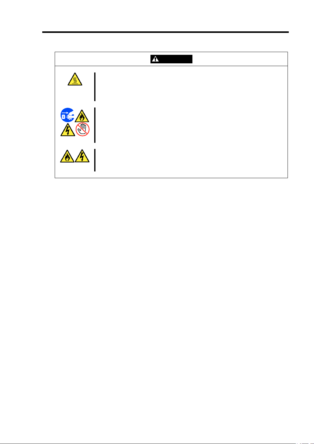
This symbol indicates the presence of a hazard if the instruction is ignored.
An image in the symbol illustrates the hazard type. (Attention)
This symbol indicates prohibited actions. An image in the symbol illustrates a
particular prohibited action. (Prohibited Action)
This symbol indicates mandatory actions. An image in the symbol illustrates a
mandatory action to avoid a particular hazard. (Mandatory Action)
(Example)
(Example)
Symbol to draw attention
Plug in to a proper power source.
Use a proper wall outlet. Use of an improper power source may cause a fire or a
power leak.
Indicates the presence of a hazard that may result in death or serious
personal injury if the instruction is ignored.
Indicates the presence of a hazard that may cause minor personal injury,
including burns, or property damage if the instruction is ignored.
Description of a danger Term indicating a degree of danger
CAUTION
Page 4
Symbols used in this User's Guide and warning labels are listed below:
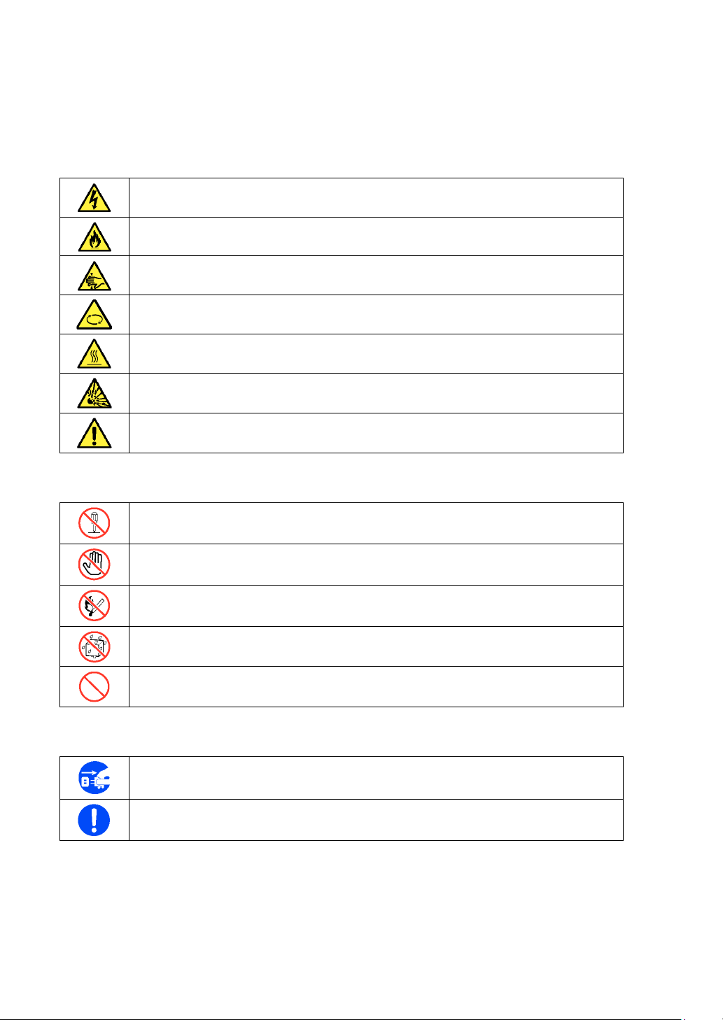
Attentions
Indicates that improper use may cause an electric shock.
Indicates that improper use may cause fumes or fire.
Indicates that improper use may cause fingers to be caught.
Indicates that improper use may cause personal injury by the moving fan blades.
Indicates that improper use may cause personal injury.
Indicates that improper use may cause explosion.
Indicates a general notice or warning that cannot be specifically identified.
Prohibited Actions
Do not disassemble, repair, or modify the server. Otherwise, an electric shock or fire
may be caused.
Do not touch any component other than specified. Otherwise, an electric shock or
personal injury such as burns may be caused.
Keep away from flame. Otherwise, a fire may be caused.
Keep away from water or liquid. Otherwise, an electric shock or fire may be caused.
Indicates a general prohibited action that cannot be specifically identified.
Mandatory Action
Unplug the power cord of the server. Otherwise, an electric shock or fire may be
caused.
Indicates a mandatory action that cannot be specifically identified. Make sure to follow
the instruction.
Page 5

NOTE: This equipment has been tested and found to comply with the limits for a Class A digital
device, pursuant to Part 15 of the FCC Rules. These limits are designed to provide reasonable
protection against harmful interference when the equipment is operated in a commercial
environment. This equipment generates, uses, and can radiate radio frequency energy and, if not
installed and used in accordance with the instruction manual, may cause harmful interference to
radio communications. Operation of this equipment in a residential area is likely to cause harmful
interference in which case the user will be required to correct the interference at his own expense.
BSMI Statement
CCC Statement
Page 6

Trademarks
NEC ESMPRO and NEC EXPRESSBUILDER are trademarks of NEC Corporation.
Microsoft, Windows, Windows Server, Windows NT, and MS-DOS are registered trademarks or trademarks of
Microsoft Corporation in the United States and other countries.
Intel and Pentium are registered trademarks of Intel Corporation.
Datalight is a registered trademark of Datalight, Inc.
ROM-DOS is a trademark of Datalight, Inc.
AT is a registered trademark of International Business Machines Corporation in the United States and other countries.
LSI, the LSI logo design, iBBU, MegaRAID, MegaRAID Storage Manager and WebBIOS are trademarks or
registered trademarks of LSI Corporation of United States.
Adaptec and its logo is a registered trademark of Adaptec, Inc. of United States.
SCSISelect is a trademark of Adaptec, Inc. of the United States.
Adobe, Adobe logo, and Acrobat are trademarks of Adobe Systems Incorporated.
All other product, brand, or trade names used in this publication are the trademarks or registered trademarks of their
respective trademark owners.
Windows Server 2003 x64 Editions stands for Microsoft® Windows® Server 2003 R2, Standard x64 Edition
Operating system and Microsoft® Windows® Server 2003 R2, Enterprise x64 Edition operating system, or
Microsoft® Windows® Server 2003, Standard x64 Edition operating system and Microsoft® Windows® Server 2003,
Enterprise x64 Edition operating system. Windows Server 2003 stands for Microsoft® Windows® Server 2003 R2,
Standard Edition operating system and Microsoft® Windows® Server 2003 R2, Enterprise Edition operating system,
or Microsoft® Windows® Server 2003, Standard Edition operating system and Microsoft® Windows® Server 2003,
Enterprise Edition operating system. Windows XP x64 Edition stands for Microsoft® Windows® XP Professional
x64 Edition operating system. Windows XP stands for Microsoft® Windows® XP Home Edition operating system
and Microsoft® Windows® XP Professional operating system. Windows 2000 stands for Microsoft® Windows®
2000 Server operating system and Microsoft® Windows® 2000 Advanced Server operating system, and Microsoft®
Windows® 2000 Professional operating system. Windows NT stands for Microsoft® Windows NT® Server network
operating system version 3.51/4.0 and Microsoft® Windows NT® Workstation operating system version 3.51/4.0.
Windows Me stands for Microsoft® Windows® Millennium Edition operating system. Windows 98 stands for
Microsoft® Windows®98 operating system. Windows 95 stands for Microsoft® Windows®95 operating system.
WinPE stands for Microsoft® Windows® Preinstallation Environment.
Momentary voltage drop prevention:
This product may be affected by a momentary voltage drop caused by lightning. To prevent a
momentary voltage drop, an AC uninterruptible power supply (UPS) unit should be used.
Notes:
(1) No part of this manual may be reproduced in any form without the prior written permission of
NEC Corporation.
(2) The contents of this User's Guide may be revised without prior notice.
(3) The contents of this User's Guide shall not be copied or altered without the prior written
permission of NEC Corporation.
(4) All efforts have been made to ensure the accuracy of all information in this User's Guide. If
you notice any part unclear, incorrect, or omitted in this User's Guide, contact the service
representative where you purchased this product.
(5) NEC assumes no liability arising from the use of this product, nor any liability for incidental or
consequential damages arising from the use of this User's Guide regardless of Item (4).
Page 7

PREFACE
Welcome to the NEC Express5800/BladeServer series server.
The NEC Express5800/BladeServer is the next generation of server technology that provides
unparalleled performance. The server may be used as a workstation PC that configures a
client-server system and provides high-speed processing and superior reliability.
Read this User's Guide thoroughly to fully understand handling of the server and to utilize its
functions to the maximum extent.
i
Page 8

ii
Chapter 1 Notes on Using Your Server
Chapter 2 General Description
Chapter 3 Setting Up
Your Server
Chapter 4 Configuring Your Server
Chapter 5 Installing the Operating System
Chapter 6 Installing and Using Utilities
Chapter 7 Maintenance
Chapter 8 Troubleshooting
Chapter 9 Upgrading Your Server
Appendix A Specification
Appendix B
Installing the Operating System
ABOUT THIS USER'S GUIDE
This User's Guide describes how to properly set up and use the server.
This User's Guide also covers useful procedures for dealing with problems that may arise during
setup or operation of the server.
Keep this manual for future use.
How to Use This User's Guide
This User's Guide contains the following information:
Provides information necessary to use the CPU blade. Make sure to read this chapter
before setting up and using the CPU blade. It also includes requirements and advisory
information for transfer and disposal of the CPU blade.
Provides information necessary to use the CPU blade, such as the names and functions of
its components.
Describes how to select a site, unpack the system, connect cables, and power on your
system.
Describes how to configure the system and provides instructions for running the BIOS
Setup Utility and the LSI Software RAID Configuration Utility, which is used to configure a
RAID array in your system.
Describes how to install the operating system.
Describes how to install the utilities for the server. It also describes using the attached NEC
EXPRESSBUILDER DVD-ROM.
Provides nformation necessary to maintain successful operation of the CPU blade.
Provides helpful information for solving problems that might occur with your system.
Describes how to upgrade your system with an additional processor, optional memory,
optional mezzanine cards, and hard disk drives.
Provides specifications for your CPU blade.
Describes how to install Microsoft Windows Server 2003 x64 Editions and Windows Server
2003 without using Express Setup.
Page 9

Text Conventions
The following conventions are used throughout this User's Guide. For safety symbols, see
"SAFETY INDICATIONS" provided earlier.
iii
IMPORTANT:
NOTE:
Items that are mandatory or require attention when using the server
Helpful and convenient piece of information
IN THE PACKAGE
The package contains various accessories, as well as the server itself. Check the packing list to
make sure that everything is included and that individual components are not damaged. If you find
any component is missing or damaged, contact your service representative.
Store the accessories in a safe place. You will need them to install an optional device or
troubleshoot the server, as well as to set it up.
Make backup copies of any included floppy disks. Store the original disks in a safe place
and use the copies when necessary.
Improper use of a provided floppy disk or CD-ROM may alter your system environment.
If you encounter an error, contact your service representative.
Page 10

iv
CONTENTS
Preface .............................................................................................................................................. i
About This User's Guide .................................................................................................................. ii
In the Package ................................................................................................................................ iii
Chapter 1 ........................................................................................................................... 1-1
Notes on Using Your Server ............................................................................................ 1-1
Safety Notes ................................................................................................................................. 1-2
For Proper Operation ................................................................................................................... 1-6
Transfer to Third Party ................................................................................................................. 1-8
Disposal and Consumables .......................................................................................................... 1-9
User Support .............................................................................................................................. 1-10
Chapter 2 ........................................................................................................................... 2-1
General Description .......................................................................................................... 2-1
Overview ...................................................................................................................................... 2-2
Standard Features ......................................................................................................................... 2-3
Part Names and Controls ............................................................................................................. 2-4
CPU Blade ............................................................................................................................... 2-4
Lamp Indications ..................................................................................................................... 2-8
Using Your Server ...................................................................................................................... 2-14
Power-on of Blade Server ...................................................................................................... 2-14
Power-off of Blade Server ..................................................................................................... 2-16
POST ..................................................................................................................................... 2-16
Device Identification ............................................................................................................. 2-19
Chapter 3 ........................................................................................................................... 3-1
Setting Up Your Server ..................................................................................................... 3-1
Before Installing CPU Blade ....................................................................................................... 3-2
Check MAC Address ............................................................................................................... 3-2
Installing DIMM ...................................................................................................................... 3-2
Installing the CPU Blade ............................................................................................................. 3-3
Making Connections .................................................................................................................... 3-4
Network ................................................................................................................................... 3-6
Page 11

v
Chapter 4 ........................................................................................................................... 4-1
Configuring Your Server .................................................................................................. 4-1
System BIOS ~ SETUP ~ ............................................................................................................. 4-1
Starting SETUP Utility ............................................................................................................. 4-2
Description of On-Screen Items and Key Usage ...................................................................... 4-3
Configuration Examples ........................................................................................................... 4-4
Menu and Parameter Descriptions ........................................................................................... 4-7
Chapter 5 ........................................................................................................................... 5-1
Installing the Operating System with Express Setup ................................................... 5-1
About Express Setup .................................................................................................................... 5-2
Microsoft Windows Server 2003 .................................................................................................. 5-3
Notes on Windows Installation ................................................................................................. 5-3
Flow of Setup................................................................................................................................ 5-7
Installing Windows Server 2003 ................................................................................................... 5-8
Installing and Setting Device Drivers ......................................................................................... 5-17
PROSet ................................................................................................................................... 5-17
Network Driver ...................................................................................................................... 5-18
Optional Network Board Driver ............................................................................................. 5-19
Adapter Fault Tolerance (AFT)/Adaptive Load Balancing (ALB) ......................................... 5-20
Graphics Accelerator Driver ................................................................................................... 5-22
Installing N8403-018 FibreChannel Controller ...................................................................... 5-22
Available switch options for Windows Server 2003 Boot.ini file .......................................... 5-23
Setting for Solving Problems ...................................................................................................... 5-24
Memory Dump (Debug Information) ..................................................................................... 5-24
Windows Dr. Watson .............................................................................................................. 5-27
Network Monitor .................................................................................................................... 5-28
Installing Maintenance Utilities .................................................................................................. 5-29
Updating the System ................................................................................................................... 5-29
Making Backup Copies of System Information .......................................................................... 5-30
Installing with the OEM-FD for Mass Storage Device .......................................................... 5-31
Chapter 6 ........................................................................................................................... 6-1
Installing and Using Utilities ........................................................................................... 6-1
NEC EXPRESSBUILDER ........................................................................................................... 6-1
Autorun Menu .......................................................................................................................... 6-5
Parameter File Creator .................................................................................................................. 6-6
Parameters File ......................................................................................................................... 6-7
NEC ESMPRO ........................................................................................................................... 6-17
NEC DianaScope ........................................................................................................................ 6-18
Page 12

vi
Chapter 7 ........................................................................................................................... 7-1
Maintenance ...................................................................................................................... 7-1
Making Backup Copies ................................................................................................................ 7-1
System Diagnostics ...................................................................................................................... 7-2
Test Items ................................................................................................................................ 7-2
Startup and Exit of System Diagnostics .................................................................................. 7-3
Chapter 8 ........................................................................................................................... 8-1
Troubleshooting ................................................................................................................ 8-1
System Viewers ............................................................................................................................ 8-2
Error Messages ............................................................................................................................ 8-3
POST Error Messages ............................................................................................................. 8-3
Lamps .......................................................................................................................................... 8-6
Solving Problems ......................................................................................................................... 8-7
CPU Blade ............................................................................................................................... 8-7
Problems with Windows ........................................................................................................ 8-13
Problems with NEC EXPRESSBUILDER ............................................................................ 8-16
Problems with Express Setup ................................................................................................ 8-17
Problems with Parameter File Creator ................................................................................... 8-18
Collecting Event Log ................................................................................................................. 8-19
Collecting Configuration Information ....................................................................................... 8-20
Collecting Dr. Watson Diagnostic Information .......................................................................... 8-20
Memory Dump ........................................................................................................................... 8-21
Recovery for Windows System .................................................................................................. 8-22
Maintenance Tools ..................................................................................................................... 8-23
Starting Maintenance Tools ................................................................................................... 8-23
Function of Maintenance Tools ............................................................................................. 8-25
Maintenance Tools with Remote Console ............................................................................. 8-27
Resetting the CPU blade ............................................................................................................ 8-29
Forced Shutdown ....................................................................................................................... 8-30
Chapter 9 ........................................................................................................................... 9-1
Upgrading Your Server ..................................................................................................... 9-1
Safety Notes ................................................................................................................................. 9-2
Anti-static Measures .................................................................................................................... 9-3
Preparation for Installation .......................................................................................................... 9-4
Installation/Removal Procedure ................................................................................................... 9-5
Processor (CPU) ...................................................................................................................... 9-5
DIMM .................................................................................................................................... 9-13
Mezzanine Card ..................................................................................................................... 9-19
Appendix A ........................................................................................................................A-1
Specifications ....................................................................................................................A-1
Page 13

vii
Appendix B ........................................................................................................................ B-1
Installing the Operating System ...................................................................................... B-1
Setup and Re-setup of CPU Blade of Diskless Model ................................................................. B-1
Local Installation ..................................................................................................................... B-1
Remote Desktop for Management ............................................................................................. B-13
Setup of Device Driver (Normally Installed in Server) ............................................................. B-14
Network Driver ..................................................................................................................... B-14
PROSet .................................................................................................................................. B-16
Graphics Accelerator ............................................................................................................. B-18
Fibre Channel Controller Driver ........................................................................................... B-18
Optional Network Board Driver ............................................................................................ B-19
Setup of Adapter Fault Tolerance (AFT)/Adaptive Load Balancing (ALB) .............................. B-20
Re-installation of the Network Driver ....................................................................................... B-23
Setting for Solving Problems ..................................................................................................... B-25
Memory Dump (Debug Information) - Windows Server 2003 - ........................................... B-25
Dr. Watson ............................................................................................................................. B-28
Network Monitor ................................................................................................................... B-29
Re-installing the Operation System if Multiple Logical Drives Exist ................................... B-30
Updating the System .................................................................................................................. B-32
Update from TS Client (Windows Server 2003 x64 Editions) .............................................. B-32
Update from TS Client (Windows Server 2003) ................................................................... B-33
Local Update ......................................................................................................................... B-34
Page 14

viii
(This page is intentionally left blank.)
Page 15

Chapter 1
Notes on Using Your Server
This chapter includes information necessary for proper and safe operation of the server.
Page 16
1-2 Notes on Using Your Server
SAFETY NOTES
This section provides notes on using the server safely. Read this section carefully to ensure proper
and safe use of the server. For symbols, see "SAFETY INDICATIONS" provided earlier.
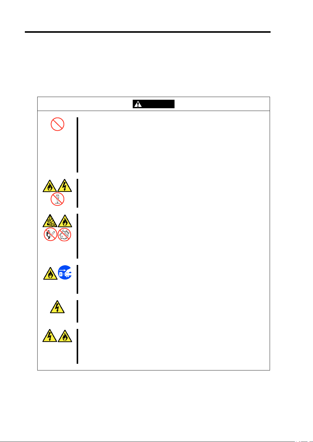
WARNING
Do not use the server for services where critical high availability may directly
affect human lives.
The server is not intended to be used with or control facilities or devices
concerning human lives, including medical devices, nuclear facilities and
devices, aeronautics and space devices, transportation facilities and devices;
and facilities and devices requiring high reliability. NEC assumes no liability
for any accident resulting in personal injury, death, or property damage if the
server has been used in the above conditions.
Do not disassemble, repair, or alter the server.
Never attempt to disassemble, repair, or alter the server on any occasion
other than described in this User's Guide. Failure to follow this instruction
may cause an electric shock or fire as well as malfunctions of the server.
Do not remove the lithium battery.
The server contains a lithium battery. Do not remove the battery. Placing the
battery near a flame or in water may cause an explosion.
When the server does not operate properly due to a dead lithium battery,
contact your service representative. Do not disassemble the server to
replace or recharge the battery yourself.
Do not use the server if any smoke, odor, or noise is present.
If smoke, odor, or noise is present, immediately turn off the system and
disconnect the power plug from the outlet, then contact your service
representative. Using the server in such conditions may cause a fire.
Keep needles or metal objects away from the server.
Do not insert needles or metal objects into ventilation holes in the server.
Doing so may cause an electric shock.
Use the devices only in the specified areas.
CPU blades and hard disk drives should be installed in a dedicated Blade
Enclosure. Do not install CPU blades and hard disk drives in a chassis other
than a Blade Enclosure. Failure to do so may result in fire and/or electric
shock.
Page 17
Notes on Using Your Server 1-3
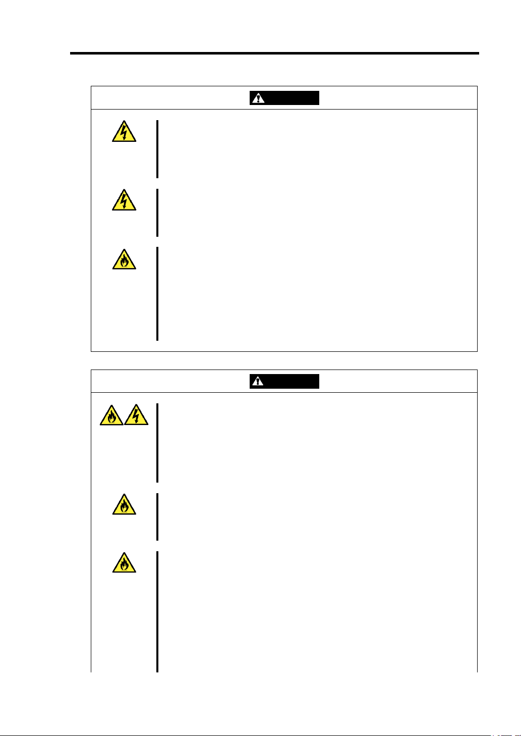
WARNING
Do not handle the CPU blade if it is installed in the Blade Enclosure.
To install or remove an option from the CPU blade, first turn off the power of
the CPU blade and remove the CPU blade from the Blade Enclosure. If you
touch parts on the CPU blade with it is connected to the Blade Enclosure,
you may receive an electric shock.
Do not install or remove more than one CPU blade at a time.
Install or remove CPU blades one by one. If you install or remove more than
one CPU blade at a time or a CPU blade with the cover of another slot
removed, you may receive an electric shock.
Do not use the equipment in a place where corrosive gases exist.
Make sure not to locate or use the server in a place where corrosive gases
(sulfur dioxide, hydrogen sulfide, nitrogen dioxide, chlorine, ammonia, ozone,
etc) exist.
Also, do not locate it in an environment where the air (or dust) includes
components accelerating corrosion (ex. sulfur, sodium chloride) or
conductive metals. There is a risk of a fire due to corrosion and shorts of the
internal printed circuit board.
CAUTION
Keep water or foreign matter away from the CPU blade.
Do not let any form of liquid (water etc.) or foreign matter (e.g., pins or paper
clips) enter the server. Failure to follow this warning may cause an electric
shock, a fire, or a failure of the server. When such things accidentally enter
the server, immediately turn off the power and disconnect the power plug
from the outlet. Do not disassemble the server. Contact your service
representative.
Make sure to complete device installation.
Always install a CPU blade, hard disk drive, and option board firmly. An
incompletely installed device may cause a contact failure, resulting in smoke
or fire.
Do not use any unauthorized interface cable.
Use only interface cables provided by NEC and locate a proper device and
connector before connecting a cable. Using an unauthorized cable or
connecting a cable to an improper destination may cause a short circuit,
resulting in a fire.
Also, observe the following notes on using and connecting an interface
cable.
Do not use a damaged cable connector.
Do not step on the cable.
Do not place any object on the cable.
Do not use the Blade Enclosure with loose cable connections.
Page 18

1-4 Notes on Using Your Server
Page 19
Notes on Using Your Server 1-5
CAUTION
Avoid installation in extreme temperature conditions.
Immediately after the server is powered off, its internal components such as
hard disk drives are very hot. Leave the server until its internal components
fully cool down before installing/removing any component.
Avoid contact with the server during thunderstorms.
Disconnect the power plug from the outlet when a thunderstorm is
approaching. If it starts thundering before you disconnect the power plug, do
not touch any part of the server including the cables. Failure to follow this
warning may cause a fire or an electric shock.
Keep animals away from the server.
Animal waste or hair may enter the CPU blade and cause a fire or electric
shock.
Page 20

1-6 Notes on Using Your Server
FOR PROPER OPERATION
Observe the following notes for proper operation of the server. Failure to observe these notes may
cause a malfunction of the server.
CPU blade
– N8400-064AF/065AF/066AF/067AF CPU blade assembly can be installed in the Blade
Enclosure (SIGMABLADE).
– Install or remove CPU blades one at a time.
– Hold the portions covered with metal plates when a CPU blade is installed or removed.
To carry a CPU blade, put it into the case in which it was packaged during shipping.
– The CPU blade is extremely sensitive to static electricity. Make sure to touch the metal
frame of the server to discharge static electricity from your body before handling the
CPU blade. Do not touch the CPU blade terminals or on-board parts with your bare
hands or place the CPU blade directly on a desk.
– Check and adjust the system clock after:
Transporting the server
Storing the server
The server halts due to environmetal operating conditions being exceeded
(temperature: 10°C - 35°C, humidity: 20% - 80%)
Check the system clock once a month. It is recommended to synchronize the system
clock using a time server (NTP server) when a high degree of time accuracy is required.
If the system clock fails to maintain sychronization despite being adjusted, contact
your sales agent.
– Store the unit under storage conditions (temperature: -10°C - 55°C, humidity: 20% -
80%, without condensation) to ensure it functions correctly when it is used again.
– Before turning off the power of a CPU blade, shut it down correctly.
– Turn on the power of the CPU blade by using the POWER switch or the remote
power-on function after waiting 30 seconds or longer after supplying AC power to the
power unit (the POWER lamp of the CPU blade lights amber). The CPU blade may not
turn on if you do not wait at least 30 seconds after supplying AC power.
– After turning off the power of a CPU blade, wait at least 30 seconds before turning it
on again.
– Remove a CPU blade after turning off its power.
Page 21

Notes on Using Your Server 1-7
– The CPU blade contains precision components that are easily affected by drastic
temperature changes. If the CPU blade is used after storage or relocation, make sure
that it is fully adapted to the operating environment.
– Make sure that any optional devices are compatible with the CPU blade. Even if an
optional device can be installed or connected to the CPU blade, it may not operate
properly and may damage the CPU blade.
– Do not perform any of the following operations during POST (including similar
operations from the EM card and external applications):
Press the POWER switch of the CPU blade.
Press the RESET switch of the CPU blade.
Remove the CPU blade from the Blade Enclosure.
Disconnect the power cord from the power unit of the Blade Enclosure.
Hard disk drive
– The hard disk drive is extremely sensitive to static electricity. Make sure to touch the
metal frame of the server to discharge static electricity from your body before handling
the hard disk drive. Do not touch the hard disk drive terminals or on-board parts with
your bare hands or place the hard disk drive directly on a desk.
– Protect the hard disk drive from excessive shock or vibration. Failure to do so may
cause the hard disk drive to fail.
– The hard disk drive should be compatible with the blade server.
– Confirm the slot to which the hard disk drive is inserted.
– The hard disk drive contains precision components that are easily affected by drastic
temperature changes. If the hard disk drive is used after storage or relocation, make
sure that it is fully adapted to the operating environment.
Optional memory, processor, mezzanine card, board, and other electronic components
– These components are extremely sensitive to static electricity. Make sure to touch the
metal frame of the server to discharge static electricity from your body before handling
the components. Do not touch the terminals or parts on the components with your bare
hands or place the components directly on a desk.
– Make sure that any optional devices are compatible with the blade server. Even if an
optional device can be installed or connected to the server, it may not operate properly
and may damage the server.
– The optional devices contain precision components that are easily affected by drastic
temperature changes. If the devices are used after storage or relocation, make sure that
they are fully adapted to the operating environment.
– It is recommended to use optional devices provided by NEC. Some memory devices
and hard disk drives from other vendors are designed to be used with the server.
However, ff such a device malfunctions and damages the server, you will be charged
the repair even within the warranty period.
Do not use a cellular phone or pager around the server.
Turn off cellular phones or pagers. Radio interference may cause malfunctions of the
server.
Page 22

1-8 Notes on Using Your Server
TRANSFER TO THIRD PARTY
The following must be observed when you transfer (or sell) the server and included software to a
third party:
Server
Make sure to provide this manual along with the server to a third party.
Provided Software
To transfer or sell any software application that comes with the server to a third party, the following
requirements must be satisfied:
All provided software applications must be transferred and no backup copies must be
retained.
The transfer requirements listed in "Software License Agreement" that comes with each
software application must be satisfied.
Software applications that are not approved for transfer must be uninstalled before
transferring the server.
Page 23
DISPOSAL AND CONSUMABLES
Dispose of the CPU blade, hard disk drives, Blade Enclosure, option board, floppy disks,
and CD/DVD-ROMs according to all national laws and regulations. Also dispose of the
power cord provided with the server to prevent it from being used with other devices.
Notes on Using Your Server 1-9
IMPORTANT:
For disposal (or replacement) of the battery on the motherboard of
the server, consult with your service representative.
Erase all hard disks, backup data cartridges, floppy disks, or other
writeable media (e.g., CD-R and CD-RW discs) to prevent your data
from being restored and used by a 3rd party. Exercise sufficient
caution to protect your privacy and confidential information.
The server contains components that have limited lifetimes and require replacement. For
stable operation of the server, NEC recommends you replace these components on a
regular basis. Consult with your service representative for replacement these components.
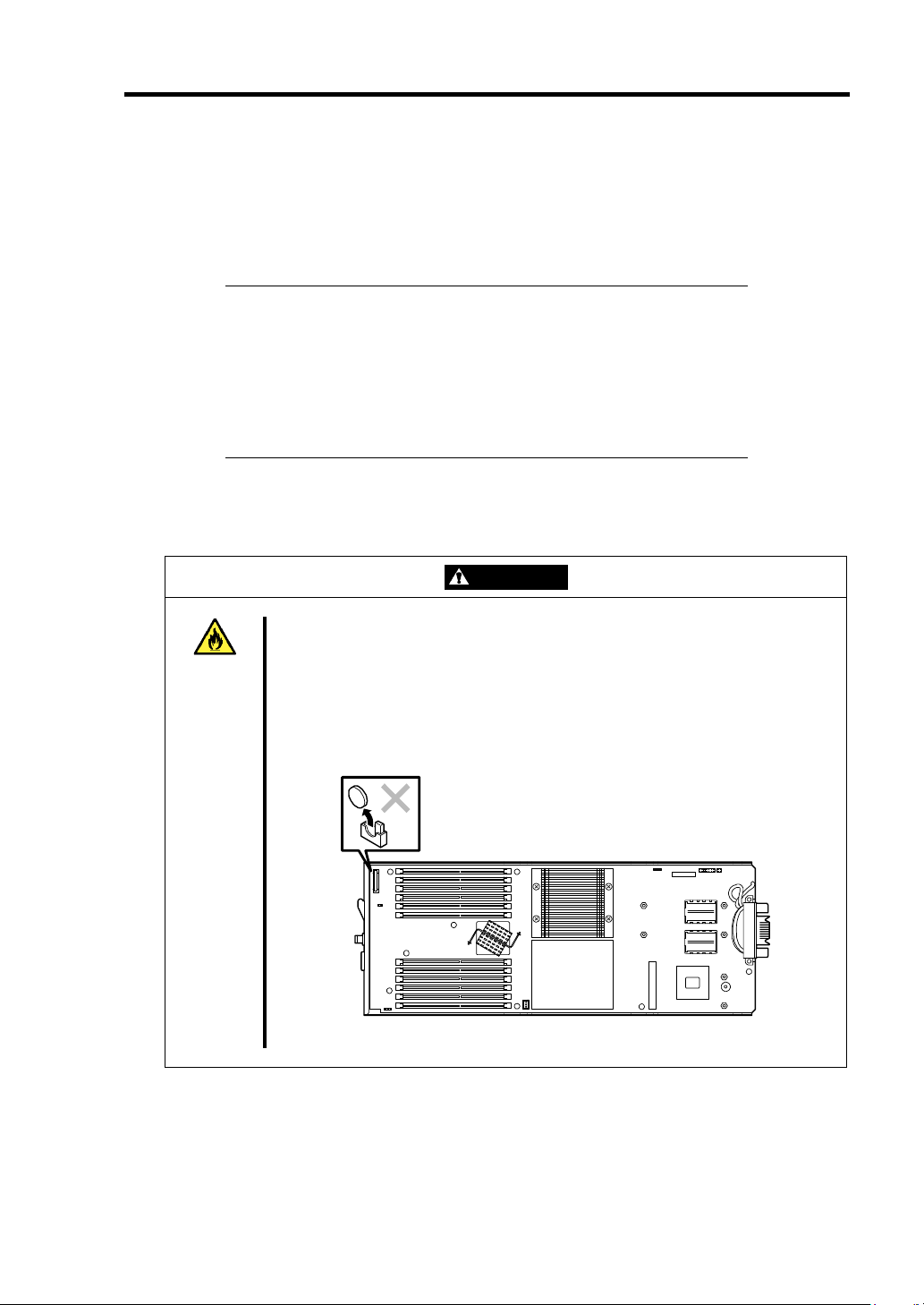
WARNING
Do not remove the battery.
The server contains a lithium battery (some optional devices may contain a
lithium, nickel cadmium, or nickel hydrogen battery). Do not remove the battery.
Placing the battery near a flame or in water may cause an explosion.
For the location of the battery on an optional device, refer to the manual
provided with the device.
CPU blade
Page 24

1-10 Notes on Using Your Server
USER SUPPORT
If the server does not function correctly, do the following before requesting repair:
1.
Check that the power cord and the cables to other devices are properly connected.
2.
See Chapter 8 to check whether your problem is described. If it is, follow the
recommended procedure to resolve it.
3.
Check that the software required for operation of the server is properly installed.
If the server still does not work properly after you have taken the above actions, consult with your
service representative immediately. Take note of the lamp indications of the server and alarm
indications on the display unit before consultation, which may provide information to your service
representative.
Page 25
Advice for Health
Notes on Using Your Server 1-11
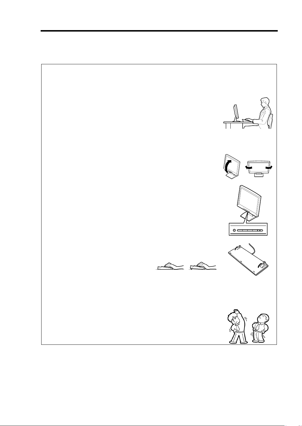
Prolonged use of a computer may affect your health. Keep in mind the
following to reduce stresses on your body:
Good Working Posture
Sit in your chair with your back straight. If the desk height is correct, you
will look down at the screen slightly and your forearms will be parallel to
the floor. This “good” work posture can minimize muscle tension caused
by sedentary work.
If you sit in a “bad” posture—for example, sit round-shouldered or with
you face too close to the display—you may easily suffer fatigue or
eyestrain.
Adjust Display Angle
Most types of displays allow you to adjust the angle vertically and
horizontally. This adjustment is very important to prevent the reflection of
light as well as to make the screen more comfortable to see. Without this
adjustment, it is difficult to maintain a “good” work posture. Be sure to
adjust the angle before using the display.
Adjust Screen Brightness and Contrast
Displays allow you to adjust brightness and contrast. Optimum brightness
and contrast vary depending on the individual, brightness of the room,
etc. If the screen is too bright or too dark, it can cause eyestrain.
Adjust Keyboard Angle
Some types of keyboards allow you to adjust the angle. If you adjust the
angle to make the keyboard more comfortable to use, you can greatly
reduce stresses on your shoulders, arms, and fingers.
Clean Equipment
Cleanliness of the equipment is very important not only for appearance
but also for function and safety. Regularly clean the display, which may
become difficult to see due to the accumulation of dust.
Fatigue and Rest
If you feel tired, refresh yourself by taking a short break or doing light
exercise.
Page 26

Chapter 2
General Description
This chapter provides information that you should be familiar with before using the server. It
includes names and functions of the components and features of the server.
Page 27
2-2 General Description
space
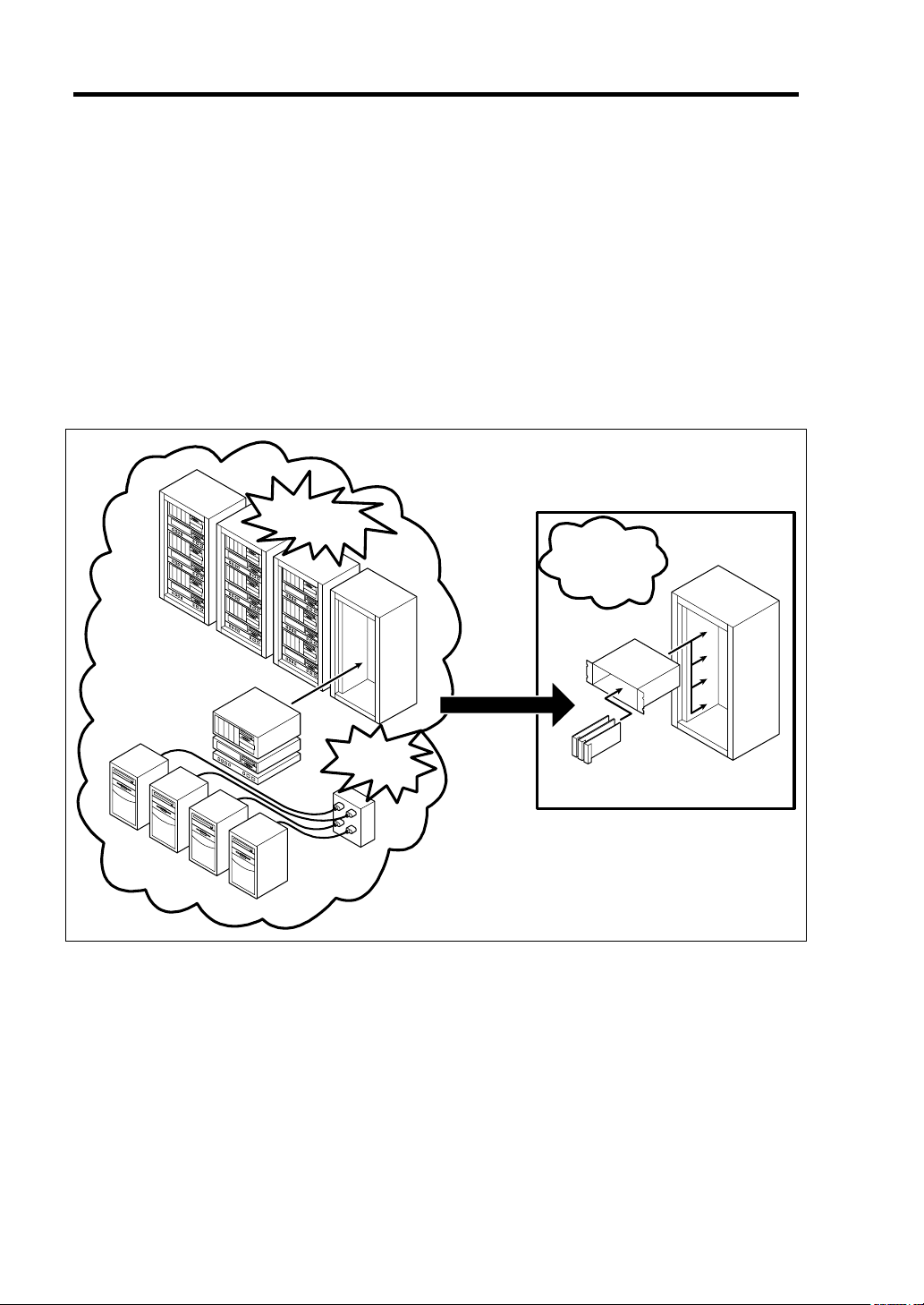
OVERVIEW
A BladeServer is a modular, multiprocessing system that includes a processor, memory, network
connection, optional add-in card slot, and associated electronics on a single motherboard, which is
called a CPU blade.
A CPU bladeis typically installed into a rack-mountable enclosure that houses multiple CPU blades
that share common resources, such as cabling, power supplies, and cooling fans.
This high-density technology reduces the installation space, lowers the total cost of ownership, and
offers increased computing density while ensuring both maximum scalability and ease of
management.
Requires more
installation space
Saves
and
power
Higher
power
consumption
Blade Enclosure
CPU blade
Page 28
STANDARD FEATURES
High performance
Expandability
High
-
reliability
Management Utilities
Available Features
Maintenance Features
Self-diagnosis
Easy Setup
General Description 2-3
Dual-Core Intel® Xeon® Processor
Quad-Core Intel
DDR2-667 SDRAM FB-DIMM
High-speed 1000BASE-T interface x2
(1Gbps supported)
High-speed disk access (SAS)
NEC ESMPRO
NEC DianaScope
Remote monitoring feature
(EXPRESSSCOPE engine)
Off-line Maintenance Utility
Memory dump feature using the DUMP
switch
NEC EXPRESSBUILDER (system
®
Xeon® Processor
Two mezzanine card slots
48GB maximum memory capacity
Up to two processors
Two network ports
Two USB 2.0 interface ports
Memory monitoring feature (correction of
correctable error/detection of
uncorrectable error)
CPU degradation feature (logical
isolation of a failed device)
Bus parity error detection
Temperature detection
Error notification
Internal voltage monitoring feature
BIOS password feature
Software power-off
Remote power-on feature
AC-Link feature
Power On Self-Test (POST)
Test and Diagnosis (T&D)
management tools)
SETUP (BIOS setup utility)
LSI Software RAID Configuration Utility
(RAID configuration utility)
Page 29
2-4 General Description
PART NAMES AND CONTROLS
This section describes the names and features of the components of the CPU blade.
CPU Blade
This section describes the names, installation positions, and features of the components of the CPU
blade.
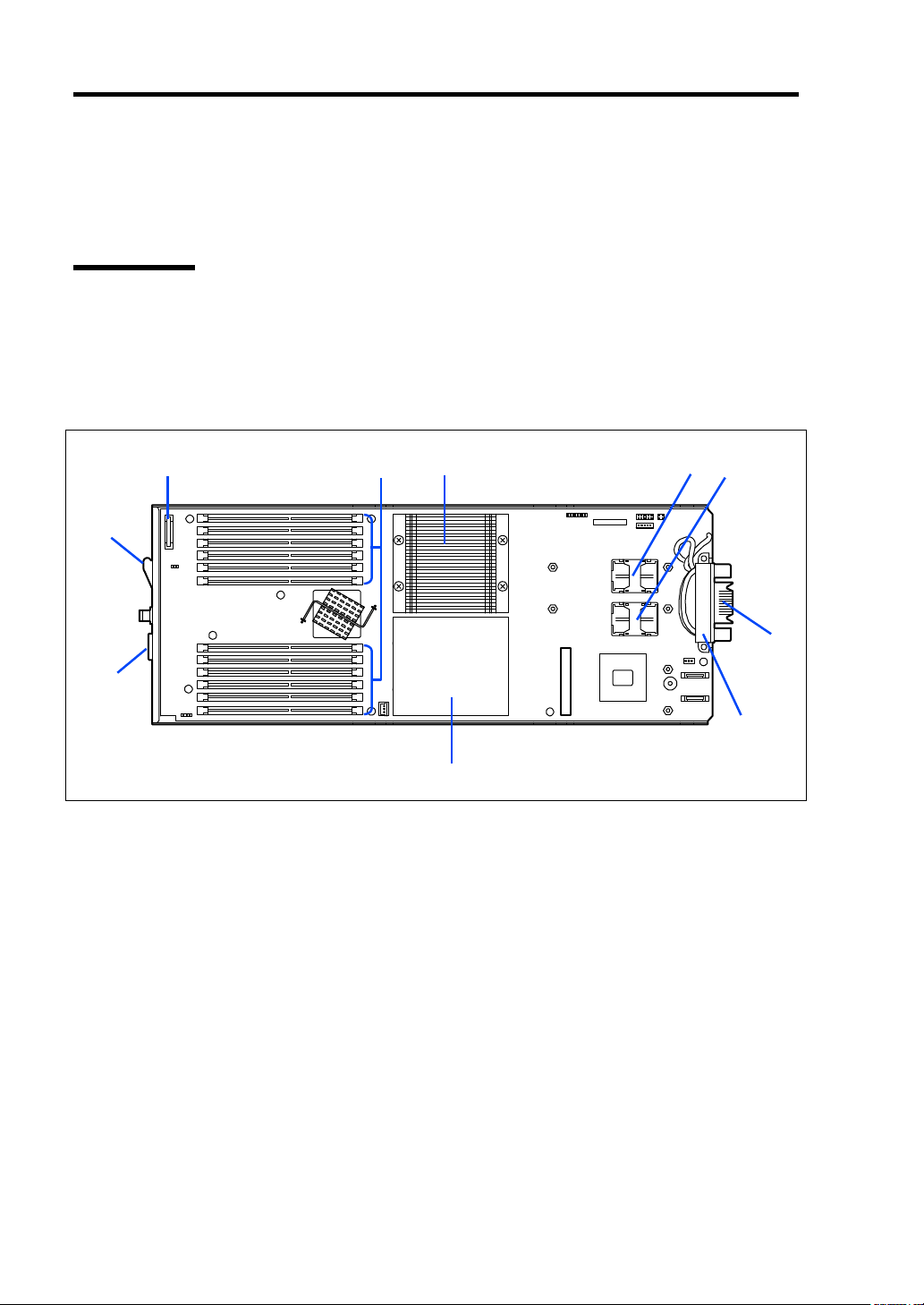
Onboard Components
1
10
9
1 Lithium battery
DIMM socket
2
#1, #5, #9, #2, #6, #10, #11, #7, #3, #12, #8, #4 from top
Heat sink
3
Install the processor #1 (CPU #1) below this heat sink.
Type II mezzanine slot
4
Slot to install mezzanine card
Type I mezzanine slot
5
Slot to install mezzanine card
6
MP connector
Used to connect with the midplane in the Blade Enclosure.
7
MAC address label
Dummy heat sink
8
Install the processor #2 (CPU #2) below this heat sink.
SUV connector
9
10 Eject lever
2
3 4 5
8
6
7
Page 30

CPU Blade Access Side
1
2
3
4
5
6
7
8
9
10
11
General Description 2-5
1
2
ID
1 POWER lamp
The lamp lights green when the CPU blade is powered on.
The lamp lights amber when the CPU blade is powered off but power is supplied from the
power supply unit.
2 POWER switch
The switch turns on or off the power of the CPU blade itself. Pressing the switch for 4
seconds or longer causes the power supply to be turned off forcibly.
3 STATUS lamp (green/amber/red)
The lamp indicates the status of the CPU blade. See "Lamp Indications" described later for
the indications of the lamp.
DUMP switch
4
Press this switch to run the memory dump.
LAN1 Link/Access lamp (green)
5
The lamp is on when LAN port 1 is connected to the network. The lamp blinks when data is
being transmitted.
6 RESET switch
Press this switch to reset the CPU blade.
LAN2 Link/Access lamp (green)
7
The lamp is on when LAN port 2 is connected to the network. The lamp blinks when data is
being transmitted.
Page 31

2-6 General Description
8 ID switch
Press this switch to turn on or off the ID lamp.
9
ID lamp (blue)
The lamp identifies the CPU blade in the system. The lamp is lit by a switch or software
command.
When the recognize command is received, the lamp blinks. If you press the ID switch, the
lamp goes on.
10
Eject lever
Pull the lever to remove the CPU blade from the Blade Enclosure.
11
SUV connector
This connector sends or receives various signals.
The K410-150(00) SUV cable is connected to this connector.
12
Hard disk drive (left: slot 0, right: slot 1)
Page 32

External View
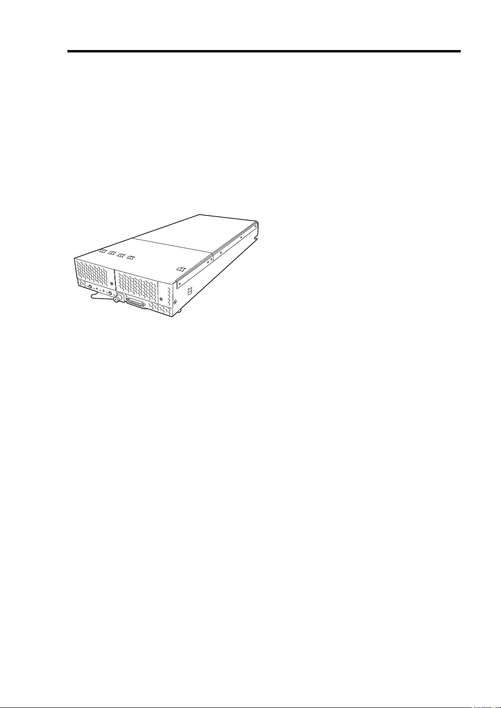
Front cover
Rear cover
CPU blade with its cover installed
General Description 2-7
DIMM
CPU blade with its cover removed
Page 33

2-8 General Description
lamp
lamp
lamp
lamp
lamp
Lamp
Indications
This section describes the positions, indications, and descriptions of the lamps on the CPU blade
and hard disk drive.
CPU Blade
The CPU blade includes five lamps.
POWER
STATUS
LAN1 Link/Access
LAN2 Link/Access
ID
1
2
ID
POWER Lamp
The POWER lamp lights green while the power of the CPU blade is on. The lamp lights amber
when the CPU blade is powered off but power is supplied from the power supply unit. The lamp is
off if power is not supplied to the system.
Page 34

General Description 2-9
STATUS Lamp
The STATUS lamp lights green when the CPU blade is operating normally. When the STATUS
lamp is flashing amber or red, it indicates that the system has failed.
In addition, you can view detailed information on the error message on the virtual LCD when the
STATUS lamp is flashing amber or red.
You can use the virtual LCD through the Web browser of EXPRESSSCOPE engine (BMC) or NEC
DianaScope Manager.
The following tables lists the indications of the STATUS lamp, their descriptions, and the actions to
take.
If an error occurs, contact your service representative.
NOTE:
If the CPU blade has NEC ESMPRO installed, you can view
the System Event Log (SEL) to identify the cause of an error.
STATUS lamp indications
STATUS lamp
Status Color
On Green The CPU blade is operating
Off –
On Red BMC is being initialized.
Flash Red See the table "Virtual LCD indications when STATUS lamp is flashing red"
Flash Amber See the table "Virtual LCD indications when STATUS lamp is flashing
Description Action
–
normally.
The power is turned off.
described later.
amber" described later.
Turn on the power.
1. Wait until the lamp goes off.
2. If the lamp is still on, check installation
of the CPU blade.
NOTE:
If the CPU blade is powered off while the STATUS lamp is
flashing amber or red, the indication of the STATUS lamp is retained.
When the CPU blade is powered on, the STATUS lamp lights green
(normal status).
Page 35

2-10 General Description
Virtual LCD indications when STATUS lamp is flashing red
On-screen message Description Action
Proc 1 IERR An error was detected in CPU#1. 1. Turn off the power and then turn
Proc 2 IERR An error was detected in CPU#2.
WDT Timeout Watchdog timer timeout error
occurred.
WDT Power Down Forcibly powered off due to
watchdog timer timeout error.
SMI Timeout A timeout error occurred while
the system management
interrupt process is in progress.
ErrPause in POST The system is waiting for key
entry due to serious POST error.
DUMP Request !
Memory U-Err XX An uncorrectable memory error
Proc Missing No CPU is installed in slot
Proc1 Config Err The CPU installed in the CPU#1
Proc2 Config Err The CPU installed in the CPU#2
BB Mez1 PwFault An error was detected in power
BB Mez2 PwFault An error was detected in power
Proc1ThermalTrip Forced power-off occurred due to
Proc2ThermalTrip Forced power-off occurred due to
Proc1 Therm % 09 A high temperature error was
Proc2 Therm % 09 A high temperature error was
AmbientTempAlm09 A high temperature error was
Under memory dump request. Wait until dump collection
was detected. XX denotes the
DIMM slot number with 1-origin
that contains the failed DIMM.
CPU#1.
slot is unsupported or its
combination is illegal.
slot is unsupported or its
combination is illegal.
circuit of mezzanine card
installed in Type I slot.
circuit of mezzanine card
installed in Type II slot.
a thermal error in CPU#1.
a thermal error in CPU#2.
detected in CPU #1.
detected in CPU #2.
detected in chassis.
it on again.
2. If an error message appears on
the POST screen, check the
message.
3. If no error message appears,
check the system by using the
Off-line Maintenance Utility.
Check the error message on the
POST screen.
completes.
1. Check the installation status of
the DIMM.
2. Replace the DIMM.
Check the installation status of the
CPU.
Check if the installed CPU is
supported by the system.
Check the CPU combination, such
as the frequency of CPU#1 and
CPU#2.
1. Check the installation status of
the mezzanine card.
2. Replace the mezzanine card.
Check if the fans in the Blade
Enclosure work normally.
Check the heat sink of the CPU
blade.
Refer to the User’s Guide of the
Blade Enclosure to make sure that
a sufficient number of fans are
installed.
Check if the fans and CPU blades
are installed in the correct locations.
Check if the ambient temperature of
the installation location satisfies the
operating conditions.
AmbientTempAlm02 A low temperature error was
detected in chassis.
Check if the ambient temperature of
the installation location satisfies the
operating conditions.
Page 36

On-screen message Description Action
Battery Alm XX A battery voltage alarm was
detected.
XX=09: Upper limit alarm
XX=02: Lower limit alarm
Proc1 Vccp AlmXX
Proc2 Vccp AlmXX
BB FSBvtt Alm XX
BB DIMMvtt AlmXX
BB +1.2v Alm XX
BB +1.5v Alm XX
BB +1.8v Alm XX
BB +3.3v Alm XX
BB +5v Alm XX
BB +1.2vs Alm XX
BB +1.5vs Alm XX
BB +1.25vs AlmXX
BB +3.3vs Alm XX
BB +5vs Alm XX
BB +12vs Alm XX
A voltage alarm was detected.
XX=09: Upper limit alarm
XX=02: Lower limit alarm
1. Check the installation status of
the battery.
2. Replace the battery.
Replace the CPU blade.
General Description 2-11
Virtual LCD indications when STATUS lamp is flashing amber
On-screen message Description Action
Mem Reconfigured The memory is degraded. 1. Check the installation status of
Mem Err Disable Correctable memory error frequently
occurs.
CPU Reconfigured The CPU is degraded. 1. Check the installation status of
E-Keying Error In the Blade Enclosure, combination
of installation locations of CPU
blade, mezzanine card, and switch
module is not correct. Thus, an
unconformity of interface signal was
detected and the CPU blade failed
to power on.
Location Error In the Blade Enclosure, the
installation location of CPU blade is
incorrect, or the installation locations
of the fan and CPU blade are
incorrect. Thus, the CPU blade
failed to power on.
the DIMM.
2. Replace the DIMM.
the CPU.
2. Replace the CPU.
Refer to the User's Guide of the
Blade Enclosure for the correct
installation locations.
Refer to the User's Guide of the
Blade Enclosure to check if the CPU
blade is installed in the correct
location.
Check the installation locations of
the fan and CPU blade.
Page 37

2-12 General Description
On-screen message Description Action
Cooling Error In the Blade Enclosure, the number
of fans installed is insufficient or the
installed fan is faulty. Thus, the CPU
blade failed to power on due to
insufficient cooling power.
Proc1 Therm % 07 A high temperature warning was
detected in CPU #1.
Proc2 Therm % 07 A high temperature warning was
detected in CPU #2.
AmbientTempAlm07 A high temperature warning was
detected in chassis.
AmbientTempAlm00 A low temperature warning was
detected in chassis.
Battery Alm XX A battery voltage warning was
detected.
XX=07: Upper limit warning
XX=00: Lower limit warning
Proc1 Vccp AlmXX
Proc2 Vccp AlmXX
BB FSBvtt Alm XX
BB DIMMvtt AlmXX
BB +1.2v Alm XX
BB +1.5v Alm XX
BB +3.3v Alm XX
BB +5v Alm XX
BB +1.2vs Alm XX
BB +1.5vs Alm XX
BB +1.25vs AlmXX
BB +3.3vs Alm XX
BB +5vs Alm XX
BB +12vs Alm XX
A voltage warning was detected.
XX=07: Upper limit warning
XX=00: Lower limit warning
Check if the fans in the Blade
Enclosure work normally.
Refer to the User’s Guide of the
Blade Enclosure to make sure that a
sufficient number of fans are
installed.
Check if the fans and CPU blades
are installed in the correct locations.
Check if the ambient temperature of
the installation location satisfies the
operating conditions.
Check if the ambient temperature of
the installation location satisfies the
operating conditions.
1. Check the installation status of
the battery.
2. Replace the battery.
Replace the CPU blade.
Page 38

General Description 2-13
LAN (1 - 2) Link/Access Lamps
The lamp is on when the LAN port is connected to the network. The lamp blinks when data is being
transmitted. When the CPU blade is powered on, it becomes ready to link with the network. The
connection of the LAN port is physically controlled by the EM card and the switch module installed
in the Blade Enclosure.
To check the connection status of the LAN port, refer to the User's Guide of the EM card and the
switch module installed in the Blade Enclosure.
ID Lamp
Pressing the ID switch turns the lamp on, and pressing it again turns the lamp off. The ID lamp
identifies a specific CPU blade in a system where more than one CPU blade is installed. Turning
this lamp on can help to identify a faulty device.
If you press the ID switch, the lamp turns on. When the recognize command is received from
management software such as NEC ESMPRO Manager and NEC DianaScope Manager, the lamp
blinks.
Page 39

2-14 General Description
USING YOUR SERVER
This section describes the basic operation of the blade server.
Power-on of Blade Server
There are two ways to turn on the power of the CPU blade. Turn on the power of the CPU blade
after turning on the power of the display unit and peripherals connected to the CPU blade.
IMPORTANT:
POWER switch or the remote power-on function after waiting 30
seconds or longer after supplying AC power to the power unit (the
POWER lamp of the CPU blade lights amber). The CPU blade may not
turn on if you do not wait at least 30 seconds after supplying AC power.
NOTES:
If a power cord on the Blade Enclosure is connected to a power
controller that includes an uninterruptible power supply (UPS),
make sure that the power of the power controller is turned on.
When power is supplied to the server, the initial diagnosis is
executed for about 30 seconds. During this period, the POWER
switch is disabled. Power on the server about 30 seconds after you
install the CPU blade or turn on the server.
Turn on the power of the CPU blade by using the
Page 40

General Description 2-15
Power ON from CPU Blade
Press the POWER switch on the panel of the CPU blade (the POWER lamp on the CPU blade lights
green).
POWER lamp
POWER switch
1
2
ID
Power ON from Network Serial Port
Depending on the BIOS setting of the CPU blade, the CPU blade may be turned on by a packet
received from the network or via the modem connected to the serial port.
This power-on procedure can be specified by setting [Wake On Events] of [System Hardware] in the
BIOS SETUP Utility.
Operation after Power ON
If the CPU blade is connected to a display unit, the NEC logo appears on the screen of the display
unit after power-on.
While the NEC logo appears, the CPU blade runs the self-diagnosis program (POST). See "POST"
described later for details. At the completion of POST, the operating system is booted.
NOTE:
error message appears. See Chapter 8.
If a fault is found during POST, POST is interrupted and an
Page 41

2-16 General Description
Power-off of Blade Server
Turn off the power in the following procedure. If a power cord of the Blade Enclosure is connected
to a UPS, refer to the manual provided with the UPS or the manual of the application controlling the
UPS.
1.
Shutdown the operating system.
2.
Press the POWER switch on the CPU blade.
The POWER lamp on the CPU blade lights amber.
<When the power of the entire system is turned off>
Shutdown all the CPU blades installed in the Blade Enclosure, turn off the power, and
remove all the power cords from the Blade Enclosure.
POST
POST (Power On Self-Test) is the self-diagnostic program of the CPU blade.
When you power on the CPU blade, the system automatically runs POST to check the motherboard,
ECC memory, CPU, keyboard, and mouse. POST also displays messages of the BIOS SETUP utility,
such as the startup message, while in progress.
With the factory setup of the CPU blade, the NEC logo appears on the display unit (if connected)
while POST is in progress. To display the POST check results, press Esc.
NOTE:
You can set the POST check results to appear on the display
unit without pressing Esc. Select "Enabled" for "Boot-time Diag
Screen" in the Advanced menu of the BIOS SETUP utility. See Chapter
4 for details.
You do not always need to check the POST check results. Check the messages that POST displays
when:
You use the blade server for the first time.
The server fails.
The server beeps several times between power-on and operating system startup.
An error message appears on the display unit.
Page 42

POST Execution Flow
The following describes the progress of POST:
IMPORTANT:
Do not make unnecessary key entries or perform mouse operations
while POST is in progress.
Some system configurations that have an optional board installed
may display the message "Press Any Key" to enter the board’s BIOS
setup. Refer to the manual provided with the optional board for
details.
After you install or remove an optional mezzanine card, POST may
halt and display a message indicating an incorrect board
configuration.
In this case, press F1 to continue POST. The board configuration
can be changed by using a utility described later.
1.
After power-on, POST starts checking the memory. The amount of basic and expansion
memory appears on the screen of the display unit (if connected). The memory check may
take a few minutes to complete depending on the memory size of the CPU blade. Also, it
may take approximately one minute for the screen display to appear after rebooting the
CPU blade.
General Description 2-17
2.
Some messages appear upon completion of the memory check. These messages indicate
that the system has detected the CPU and other installed devices.
3.
After a few seconds, POST displays the following message prompting you to enter the
BIOS setup utility. The following message appears at the bottom left of the screen:
Press <F2> to enter SETUP
Launch the BIOS SETUP utility when you need to change the settings of the CPU blade.
As long as the above message is not displayed with an error message, you do not have to
launch the utility. POST will automatically proceed.
To launch the SETUP utility, press F2 while the above message is displayed. See Chapter
4 for setup and parameters.
The CPU blade automatically restarts POST when you exit the SETUP utility.
4.
If the server has an optional board installed, POST displays the board information on the
screen.
Refer to the manual provided with the board for details.
POST will automatically proceed a few seconds later.
Page 43

2-18 General Description
5.
If you have set the password using the BIOS SETUP utility, the password entry screen
appears upon successful completion of POST.
Up to three password entries will be accepted. Three incorrect password entries disable
the system. In this case, turn off the power and wait about 30 seconds before turning it on
again.
IMPORTANT:
system.
6.
The operating system starts when POST completes.
Do not set a password before installing the operating
POST Error Messages
When POST detects an error, it displays an error message on the screen. See Chapter 8 for POST
error codes.
IMPORTANT:
consulting with your service representative; they may provide useful
information for maintenance.
Take note of the error messages displayed before
Page 44

General Description 2-19
Device Identification
When more than one CPU blade of the same type is installed, use the ID lamp to identify the CPU
blade requiring maintenance.
The ID lamp is located on the CPU blade installed in the Blade Enclosure.
The ID lamp also blinks blue when software commands from the management PC on the network
are used. In addition, pressing the ID switch on the CPU blade illuminates the ID lamp.
1
ID switch
ID lamp
2
ID
Page 45

Chapter 3
Setting Up Your Server
This chapter describes how to set up the server on a step-by-step basis.
Page 46

3-2 Setting Up Your Server
BEFORE INSTALLING CPU BLADE
Be sure to check the MAC addresses before installing a CPU blade in the Blade Enclosure.
Check MAC Address
A MAC address indicates the address specific for the network. It is a 12-digit alphanumeric string
starting with "003013." A CPU blade has two MAC addresses. Check the MAC addresses before
installing a CPU blade in the Blade Enclosure.
A MAC address is shown in the figure below:
Label indicating
MAC address
The address of the LAN port depends on the number and letter of the last character of the MAC
address.
When the number/letter of the last character is an even number or A, C, or E:
The MAC address for LAN port 1 is as described on the label.
The MAC address for LAN port 2 can be obtained by adding 1 to the MAC address.
When the number/letter of the last character is an odd number or B, D, or F:
The MAC address for LAN port 1 can be obtained by adding 1 to the MAC address.
The MAC address for LAN port 2 can be obtained by adding 2 to the MAC address.
The MAC addresses can be checked by using a Windows or Linux command.
Windows
Enter "ipconfig /all" in the MS-DOS prompt or from [Run] in the Start menu to see the
indicated physical address part.
Linux
Enter "ifconfig" in the prompt to see the indicated "Hwaddr."
Installing DIMM
If your CPU blade is not equipped with memory, install DIMM’s according to Chapter 9.
Two DIMM’s must be populated in a pair.
Page 47

Setting Up Your Server 3-3
INSTALLING THE CPU BLADE
Install the CPU blade in a dedicated Blade Enclosure. Refer to the User's Guide of the Blade
Enclosure for how to install the CPU blade.
IMPORTANT:
electricity. Make sure to touch the metal frame of the CPU blade to
discharge static electricity from your body before handling the CPU
blade. Do not touch the pins, leads, or circuitry or place the CPU blade
directly on a desk. For static notes, see "Anti-static Measures" in
Chapter 9.
The CPU blade is extremely sensitive to static
Page 48

3-4 Setting Up Your Server
MAKING CONNECTIONS
Connect peripheral devices to the CPU blade.
IMPORTANT:
Contact the maintenance engineer or your service representative for
information on configuring an uninterruptible power supply system
or auto power controller and the time schedule operation.
If you are installing the CPU blade in the Blade Enclosure
(SIGMABLADE), follow the instructions described in the User's
Guide of the Blade Enclosure.
WARNING
Observe the following instructions to use the server safely. Failure to follow
these instructions may result in death or serious personal injury. See pages 1-2
to 1-6 for details.
Do not hold the power plug with wet hands.
Do not connect earth lines to any gas tubes.
CAUTION
Observe the following instructions to use the server safely. Failure to follow
these instructions may cause a fire, personal injury, or property damage. See
pages 1-2 to 1-6 for details.
Do not plug the power cord into an improper power source.
Do not connect the power cord to an outlet that has an illegal number of
connections.
Insert the power plug into the outlet as far as it goes.
Use the authorized power cord only.
Do not connect or disconnect any interface cable with the power cord of the
server plugged into a power source.
Do not use any unauthorized interface cable.
Page 49
Setting Up Your Server 3-5
During normal operation, interface cables do not need to be connected to a CPU blade. Cables
should be connected to the USB, serial, and/or VGA ports on the CPU blade in the following cases:
Installing an operating system when the CPU blade is installed in the Blade Enclosure
(SIGMABLADE-H).
Maintenance.
Updating BIOS and firmware.
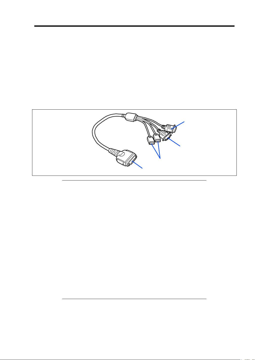
The K410-150(00) SUV cable is a standard accessory for the Blade Enclosure (SIGMABLADE).
The K410-150(00) SUV cable has USB, serial interface, and monitor connection connectors.
Connect a device to each of the cable’s connectors as necessary.
To serial interface device
To monitor
To USB devices
To CPU blade
IMPORTANT:
To connect a peripheral or interface cable provided by a vendor
other than NEC to the CPU blade, make sure that the device is
compatible with the CPU blade. Some third party devices are not
compatible with the CPU blade.
The serial port connector cannot be directly connected to a leased
line.
Do not connect/disconnect the SUV cable or add/remove a USB
device until the operating system starts up.
To connect/disconnect the SUV cable or add/remove a USB device
after operating system startup, follow the operating system
procedure.
If a device with a serial interface is connected, power off the CPU
blade and device. Then, remove the power cord from the device
before connecting/disconnecting the SUV or serial cable. Failure to
do so may cause the device to malfunction.
If the CPU blade is installed in the Blade Enclosure
(SIGMABLADE-H) and you need to install an operating system,
use the SUV cable. See the next page for connecting the cable.
Page 50

3-6 Setting Up Your Server
USB Connection by K410-150(00) SUV Cable
Connect the floppy disk drive, DVD-ROM drive, keyboard, and mouse according to the figure
shown below.
A USB hub should be self-powered if it is used. Use N8460-005.
Display unit
1
2
ID
USB
USB
CPU blade
* When you use the N8460-009 external
DVD-ROM drive, use the branch USB
cable provided with the CPU blade.
External floppy disk drive
External DVD-ROM drive *
Self-powered
USB hub
Mouse
Keyboard
Network
The CPU blade is connected to the network via the Blade Enclosure. Refer to the User's Guide of
the Blade Enclosure for details.
Page 51

Chapter 4
Configuring Your Server
This chapter describes Basic Input Output System (BIOS) configuration.
When you install the Bade Server for the first time or install/remove optional devices, read this
chapter to understand the correct setup procedures.
SYSTEM BIOS ~ SETUP ~
The SETUP utility is provided to configure the basic hardware settings of the CPU blade. This
utility is pre-installed in the flash memory of the CPU blade.
The CPU blade is pre-configured with the optimal parameters for system performance. Therefore,
you do not need to use the SETUP utility except in the cases described below.
IMPORTANT:
The SETUP utility is intended for system administrator use only.
The SETUP utility allows you to set a password. The CPU blade is
provided with two levels of password: Supervisor and User. With
the Supervisor password, you can view and change all system
parameters of the SETUP utility. With the User password, the
system parameters you can view and change are limited.
Do not set a password before installing the operating system.
The CPU blade contains the latest version of the SETUP utility. The
menus and descriptions that appear in your SETUP utility may
differ from the descriptions in this manual. If you find anything
unclear, see the online help or contact your sales representative.
Page 52

4-2 Configuring Your Server
Starting SETUP Utility
Powering on the CPU blade starts POST (Power On Self-Test) and displays its check results. If the
NEC logo is displayed, press Esc.
After a while, the following message appears at the bottom left of the screen:
Press <F2> to enter SETUP
Press F2 to start the SETUP utility and display its Main menu.
If you have previously set a password with the SETUP utility, the password entry screen appears.
Enter the password.
Enter password:[ ]
Up to three password entries will be accepted. Three incorrect password entries disable the system.
In this case, turn off the power and wait about 30 seconds before turning it on again.
NOTE:
Supervisor and User. With the Supervisor password, you can view and
change all system parameters. With the User password, the system
parameters you can view and change are limited.
The CPU blade is provided with two levels of password:
Page 53

Configuring Your Server 4-3
w
Description of On-Screen Items and Key Usage
Use the following keyboard keys to navigate the SETUP utility (the key functions are also listed at
the bottom of the screen).
Indicates the current menu.
Indicates
there are
submenus.
Online help
Setup item
menu
indow
Explanation of key functions
Parameter (highlights when selected)
Cursor (↑, ↓):
Cursor (←, →):
– and +:
Enter: Press Enter to select the parameters.
Esc:
F1: Press F1 when you need help on SETUP operations. The help
F9:
F10:
Selects an item on the screen. The highlighted item is currently
selected.
Selects the Main, Advanced, Security, Server, Boot, or Exit menu.
Changes the value (parameter) of the selected item. When a
submenu option (an option preceded by "►") is selected, these
keys are disabled.
Displays the previous screen.
screen for SETUP operations appears. Press Esc to return to the
previous screen.
Sets the parameter of the currently displayed item back to the
factory set parameter.
Save and exit the SETUP utility.
Page 54

4-4 Configuring Your Server
Configuration Examples
The following describes examples of the configuration settings required to use software-link
features or for system operations.
Date and Time
To change system date or time
Select [Main] – [System Time] and [System Date].
Set the correct date and time before using the system.
Link with Management Software
To control the power supply of the CPU blade with NEC ESMPRO Manager via the
network
Select [Advanced] – [Advanced Chipset Control] – [Wake On LAN/PME] – [Enabled].
Boot
To change the boot order of devices connected to the CPU blade
Select [Boot] and specify the boot order.
To display POST check results
Select [Advanced] – [Boot-time Diagnostic Screen] – [Enabled].
You can also press Esc while the NEC logo is on the screen to display POST check
results.
To use the remote wake-up feature
Via Modem:
[Advanced] – [Advanced Chipset Control] – [Wake on Ring] – [Enabled]
Via LAN:
[Advanced] – [Advanced Chipset Control] – [Wake on LAN/PME] – [Enabled]
Via optional card:
[Advanced] – [Advanced Chipset Control] – [Wake on LAN/PME] – [Enabled]
Via RTC alarm:
[Advanced] – [Advanced Chipset Control] – [Wake on RTC Alarm] – [Enabled]
To control from the HW console
Select [Server] – [Console Redirection] and configure each item.
Page 55

Memory
To pause POST if a memory error is detected
Select [Advanced] – [Memory/Processor Error] – [Halt].
To check the installed memory (DIMM) status
Select [Advanced] – [Memory Configuration] – [DIMM Group #1 - #2 Status] and check
the status indications.
To clear the memory (DIMM) error information
Select [Advanced] – [Memory Configuration] – [Memory Retest] – [Yes] and reboot the
system.
CPU
To pause POST if the system detects a CPU error
Select [Advanced] – [Memory/Processor Error] – [Halt].
To check the installed CPU status
Select [Main] – [Processor Settings] and check the status indications.
Configuring Your Server 4-5
The on-screen CPU numbers and socket locations on the motherboard are associated as
shown in the figure below:
To clear the CPU error information
Select [Main] – [Processor Settings] – [Processor Retest] – [Yes] and reboot the system.
Keyboard
To set Numlock and key repeat
CPU #1 (to be installed below the heat sink)
CPU #2 (to be installed below the dummy heat sink)
Select [Advanced] – [NumLock] – [On].
Page 56

4-6 Configuring Your Server
Security
To set BIOS passwords
Select [Security] – [Set Supervisor Password] and enter a password.
Set the Supervisor password first, and then the User password.
To enable/disable the POWER switch
Select [Security] – [Power Switch Inhibit] – [Disabled].
Select [Security] – [Power Switch Inhibit] – [Enabled].
To set this item, the Supervisor and User passwords must be set.
IMPORTANT:
forced shutdown procedure is still available.
Even if [Power Switch Inhibit] is set to [Enabled], the
External Devices
To set up external devices
Select [Advanced] – [Peripheral Configuration] and set up each device.
Internal Devices
To set up internal PCI devices of the CPU blade
Select [Advanced] – [PCI Configuration] and set up each device.
To clear the hardware configuration data (after installing/removing internal devices)
Select [Advanced] – [Reset Configuration Data] – [Yes].
Saving the Configuration Data
To save the BIOS configuration data
Select [Exit] – [Exit Saving Changes] or [Save Changes].
To discard changes to the BIOS configuration data
Select [Exit] – [Exit Discarding Changes] or [Discard Changes].
To load the default BIOS configuration data (may differ from factory-set values)
Select [Exit] – [Load Setup Defaults].
To save the current settings as a user-defined configuration
Select [Exit] – [Save Custom Defaults].
To load the user-defined configuration data
Select [Exit] – [Load Custom Defaults].
Page 57

Configuring Your Server 4-7
Menu and Parameter Descriptions
The SETUP utility has the following six menus:
Main
Advanced
Security
Server
Boot
Exit
To set specific functions, select a submenu from the above menus. The following describes the
available options and their descriptions for each menu, as well as the factory-set values.
Main
Start the SETUP utility to display the Main menu.
Available options in the Main menu are listed below:
Option Parameter Description Your Setting
System Time HH:MM:SS Specify the current time.
System Date MM/DD/YYYY Specify the current date.
[ ]: Factory-set
IMPORTANT:
If the system clock fails to maintain sychronization
despite being adjusted, contact your sales agent.
Page 58
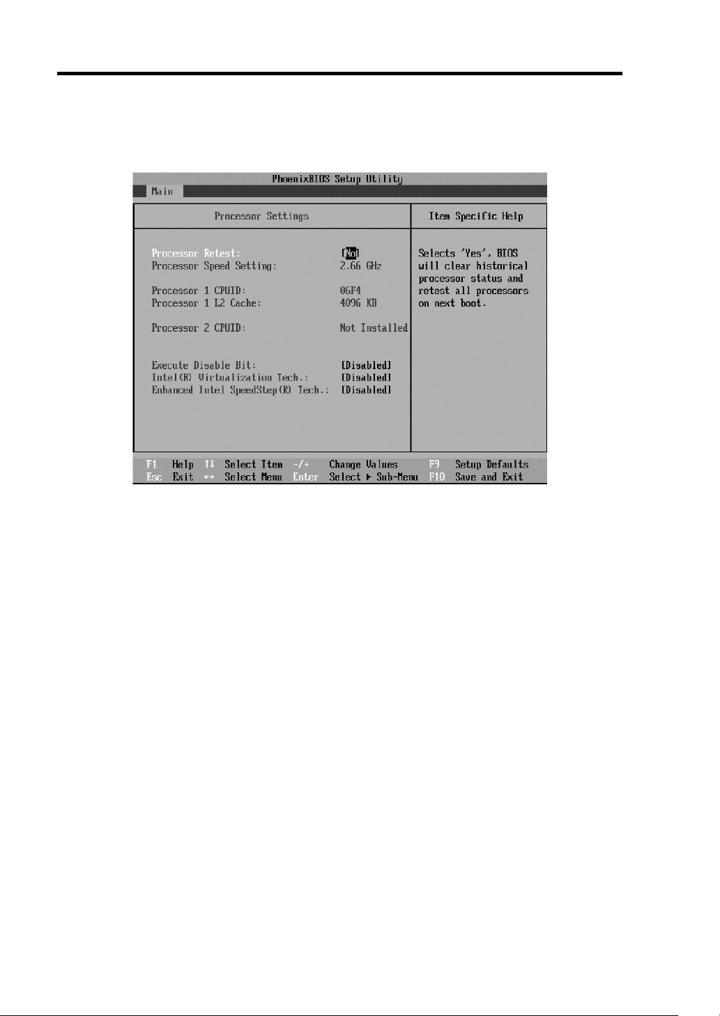
4-8 Configuring Your Server
Processor Settings
Select "Processor Settings" on the Main menu to display the following screen :
Page 59

Configuring Your Server 4-9
See the table below for the options and their descriptions:
Option Parameter Description Your Setting
Processor Retest [No]
Yes
Processor Speed
Setting
Processor 1 CPUID Numeral
Processor 1 L2 Cache – Indicates the cache size of processor
Processor 2 CPUID Numeral
Processor 2 L2 Cache – Indicates the cache size of processor
Execute Disable Bit Disabled
Intel(R) Virtualization
Tech.
Enhanced Intel
SpeedStep(R) Tech.
[ ]: Factory-set
– Indicates the frequency of the CPU.
Disabled
Not installed
Disabled
Not installed
[Enabled]
[Disabled]
Enabled
[Disabled]
Enabled
Clears the error information on the
CPU.
A numeral indicates the ID of
processor 1.
"Disabled" indicates that the
processor is defective.
"Not Installed" indicates that the
processor is not installed.
1.
A numeral indicates the ID of
processor 2.
"Disabled" indicates that the
processor is defective.
"Not Installed" indicates that the
processor is not installed.
2.
Specify whether the HW DEP feature
is enabled or disabled.
Specify whether the virtualization
technology of the Intel(R) processor is
enabled or disabled.
Specify whether the Enhanced Intel
SpeedStep(R) Technology feature is
enabled or disabled.
If the CPU does not support this
feature, this option is not available.
Page 60

4-10 Configuring Your Server
Advanced
Move the cursor onto "Advanced" to display the Advanced menu.
"
Selecting a menu item preceded by the symbol "►
and pressing Enter displays the submenu.
See the table below for the options and their descriptions:
Option Parameter Description Your Setting
Boot-time
Diagnostic Screen
Reset
Configuration Data
NumLock On
Memory/Processor
Error
[ ]: Factory-set
[Disabled]
Enabled
[No]
Yes
[Off]
[Boot]
Halt
Specify whether the self-diagnosis (POST)
screen is displayed or not at boot.
If this item is set to "Disabled," the "NEC"
logo appears during POST (pressing Esc
displays the POST screen).
Set this item to "Yes" to clear the
configuration data (system information
stored by POST). The parameter is changed
to "No" after the system is booted.
Specify whether the NumLock feature is
enabled or disabled.
The boot up operation pauses at the end of
POST if a memory or CPU error occurs.
Page 61

Configuring Your Server 4-11
Memory Configuration
Select "Memory Configuration" on the Advanced menu to display the following screen:
See the table below for the options and their descriptions:
Option Parameter Description Your Setting
Memory Size – Indicates the total capacity of installed
memory.
DIMM Group #1 #6 Status
Memory Retest [No]
Extended RAM
Step
[ ]: Factory-set
Normal
Disabled
Not installed
Yes
1MB
1KB
Every Location
[Disabled]
Indicates the current memory status.
"Normal" indicates that the memory is
operating normally.
"Disabled" indicates that one or more
memory devices are defective.
Clears the error information on
memory.
"1MB" indicates that the memory test
is done in units of 1MB. "1KB"
indicates that the memory test is done
in units of 1KB. "Every-location"
indicates that every memory device is
tested. "Disabled" indicates that only
memory initialization is done.
Page 62
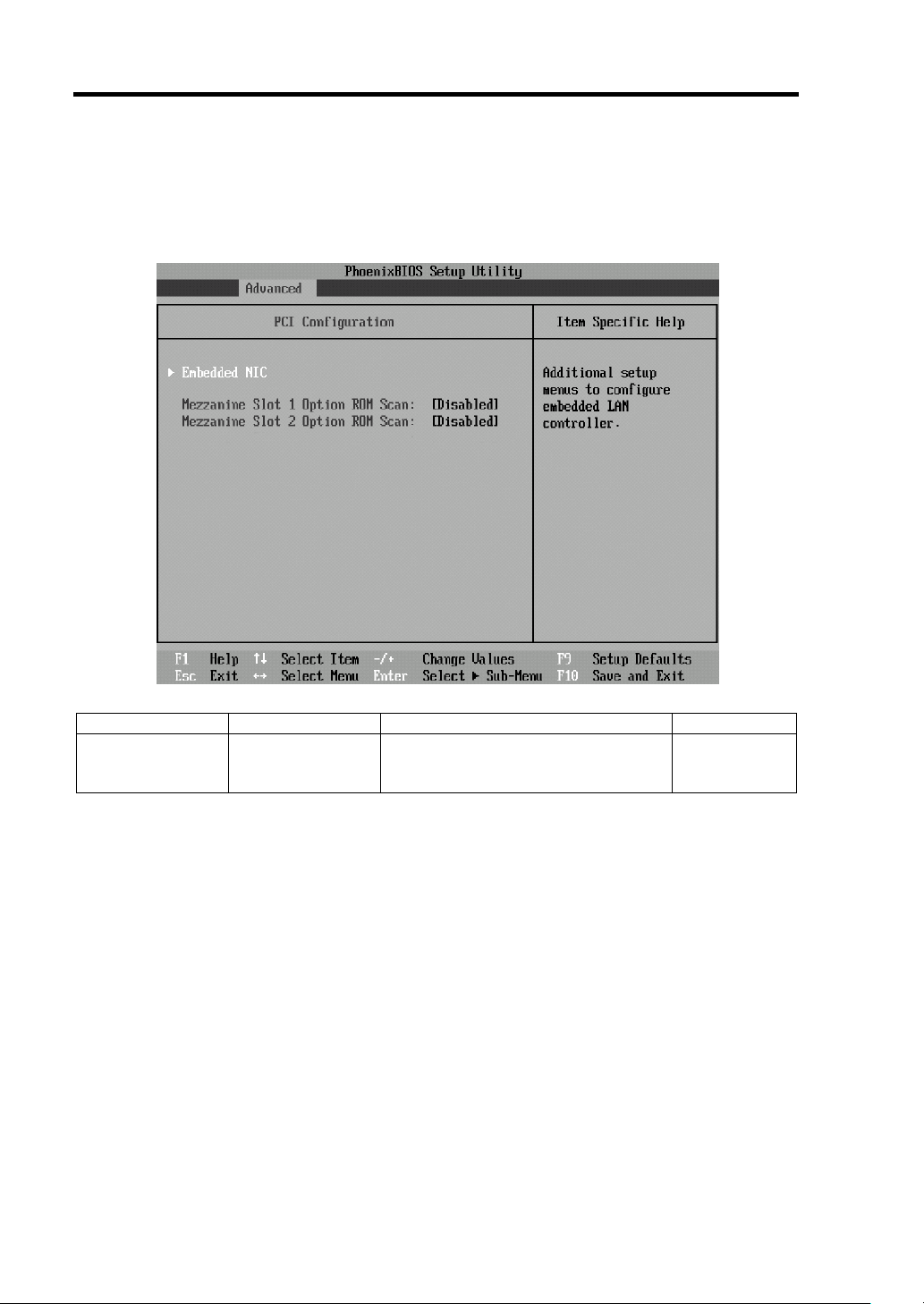
4-12 Configuring Your Server
PCI Configuration
Select "PCI Configuration" on the Advanced menu to display the following screen.
Selecting a menu item preceded by the symbol "►
"
and pressing Enter displays the submenu.
Option Parameter Description Your Setting
Mezzanine Slot
1-2 Option ROM
Scan
[ ]: Factory-set
Enabled
[Disabled]
Specify whether the BIOS of the
mezzanine card is enabled or
disabled.
– Embedded NIC
See Page 4-14.
Page 63
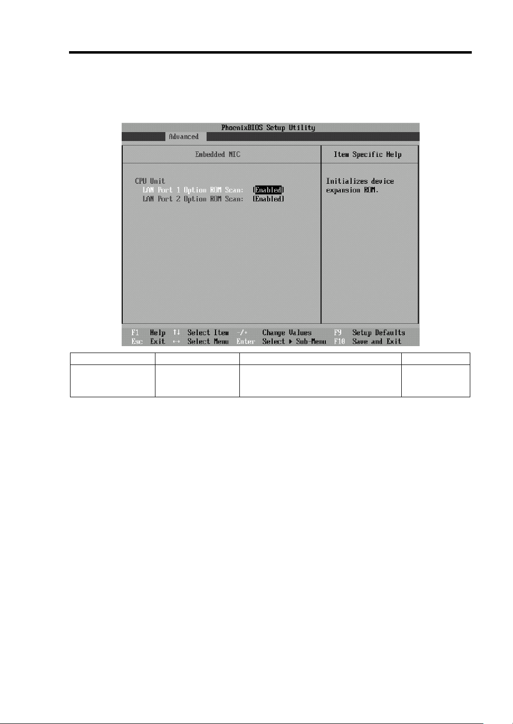
Configuring Your Server 4-13
Embedded NIC
Select "Embedded NIC" on the PCI Configuration submenu to display the following screen:
Option Parameter Description Your Setting
LAN Port 1 - 2
Option ROM Scan
[ ]: Factory-set
[Enabled]
Disabled
Specify whether the BIOS of the
on-board LAN controller is enabled or
disabled.
Page 64

4-14 Configuring Your Server
Peripheral Configuration
Select "Peripheral Configuration" on the Advanced menu to display the following screen:
See the table below for the options and their descriptions.
IMPORTANT:
Make sure to avoid any conflicts in the interrupt
requests or the base I/O addresses. If an assigned value is already used
by another resource, it appears in yellow. A yellow value must be
reassigned.
Option Parameter Description Your Setting
Serial Port B Disabled
[Enabled]
Base I/O Address 3F8h
[2F8h]
3E8h
2E8h
Interrupt [IRQ 3]
IRQ 4
[ ]: Factory-set
Specify whether serial port B is
enabled or disabled.
Specify the base I/O address for serial
port B.
Specify the interrupt for serial port B.
Page 65
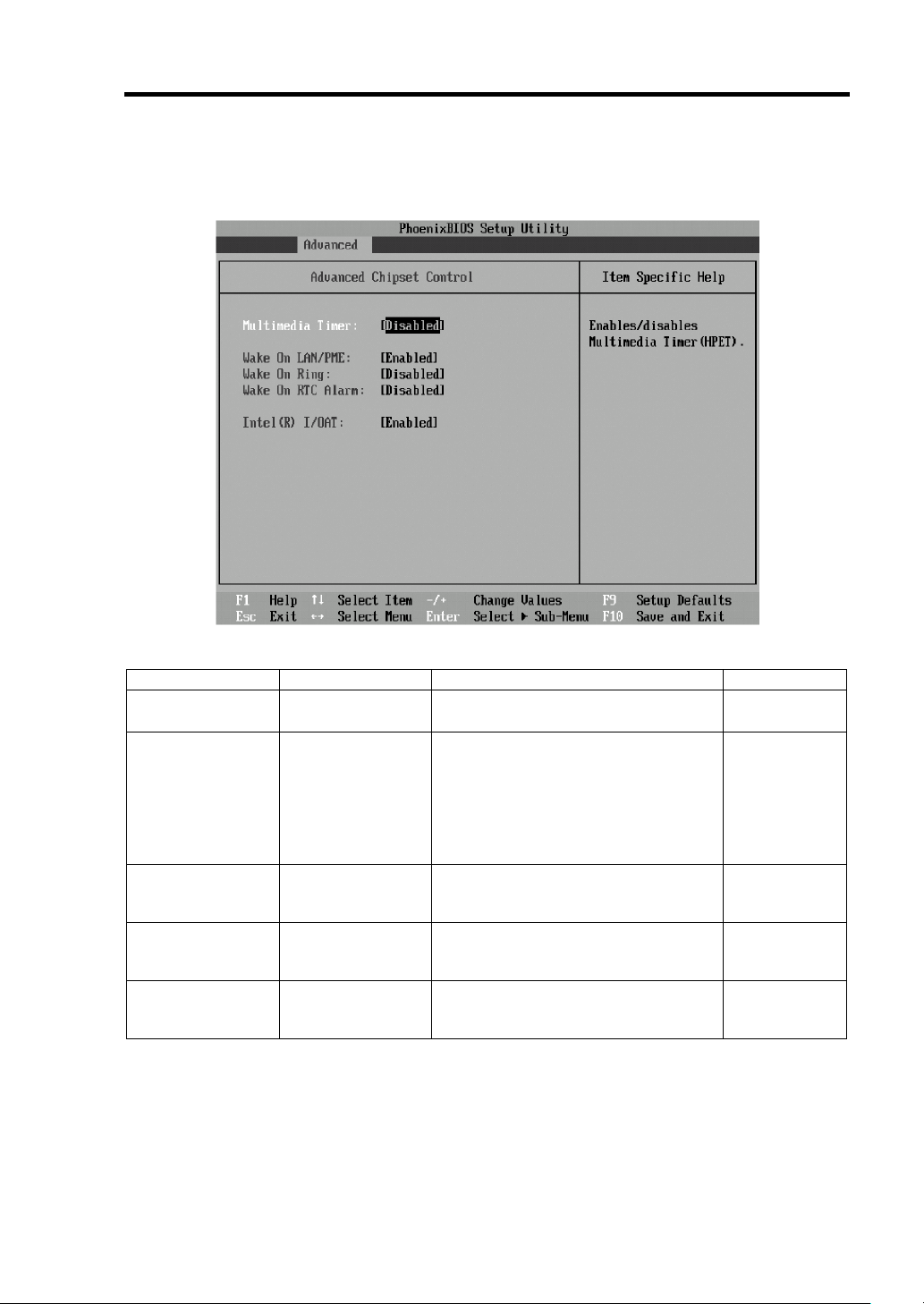
Configuring Your Server 4-15
Advanced Chipset Control
Select "Advanced Chipset Control" on the Advanced menu to display the following screen:
See the table below for the options and their descriptions:
Option Parameter Description Your Setting
Multimedia Timer [Disabled]
Enabled
Wake On
LAN/PME
Wake On Ring [Disabled]
Wake On RTC
Alarm
Intel(R) I/OAT Disabled
[ ]: Factory-set
Disabled
[Enabled]
Enabled
[Disabled]
Enabled
[Enabled]
Specify whether the multimedia timer
is enabled or disabled.
Specify whether the remote power-on
feature through a device connected to
the standard network card or
expansion slot card is enabled or
disabled. To use the Wake On LAN
feature, set the link speed and duplex
to [Auto].
Specify whether the remote power-on
feature through a serial port (modem)
is enabled or disabled.
Specify whether the remote power-on
feature using the RTC alarm is
enabled or disabled.
Specify whether the Intel(R) I/O
acceleration technology is enabled or
disabled.
Page 66

4-16 Configuring Your Server
Security
Move the cursor onto "Security" to display the Security menu.
These items are displayed only when the
User Password is set.
Page 67

Configuring Your Server 4-17
Select "Set Supervisor Password" or "Set User Password" and press Enter to display the following
dialog box. Note that "Set User Password" is not available if the Supervisor password is not set.
Enter a password of up to seven alphanumeric characters and symbols in this dialog box.
IMPORTANT:
"Set User Password" is not available if the Supervisor password is
not set.
Do not set a password before installing the operating system.
If you have forgotten your password, contact your service
representative.
Page 68

4-18 Configuring Your Server
Enter
Enter
See the table below for the options and their descriptions:
Option Parameter Description Your Setting
Set User
Password
Set Supervisor
Password
Password on
boot
Secure Mode
Timer
Hot Key
(CTRL+ALT+)
Secure Mode
Boot
Power Switch
Inhibit
[ ]: Factory-set
Up to 7
alphanumeric
characters
Up to 7
alphanumeric
characters
[Disabled]
Enabled
[Disabled]
1 min
2 min
5 min
10 min
20 min
60 min
120 min
[L]
Z
[Disabled]
Enabled
[Disabled]
Enabled
Press
entry screen. With a User password, the
available SETUP menus are restricted. This
option is available only if the Supervisor
password is set.
Press
password entry screen. With the Supervisor
password, all SETUP menus are available.
This option is available only when you log
into the SETUP utility with the Supervisor
password.
Specify whether to request password entry
on boot. User password setup is required
beforehand. When the supervisor password
is specified and this option is disabled, the
BIOS assumes that a boot attempt is made
by a user.
It gives priority to "Secure Mode Boot" when
"Secure Mode Boot" and "Password on boot"
are both enabled.
Specify the idle period for the system to enter
Secure Mode. If this item is set to [Disabled],
the timer is unavailable.
Specify the key to enter Secure Mode. Press
the selected key while pressing Ctrl and Alt
to enter Secure Mode.
Specify whether the system starts in Secure
Mode or not.
Specify whether the POWER switch of the
CPU blade is enabled or disabled. If
Enabled, the POWER switch cannot be used
to power off the CPU blade. The forced
shutdown procedure (pressing the POWER
switch for at least 4 seconds) is still available.
to display the User password
to display the Supervisor
IMPORTANT:
Secure Mode is used to restrict the access of a user
who has no user password.
In Secure Mode, the POWER switch, DUMP switch, keyboard, and
mouse are disabled, and the ScrollLock, CapsLock, and NumLock
lamps on the keyboard flashsequentially.
To exit Secure Mode, enter the user password.
Page 69

Server
Move the cursor onto "Server" to display the server menu.
"
Selecting a menu item preceded by the symbol "►
and pressing Enter displays the submenu.
Configuring Your Server 4-19
Page 70

4-20 Configuring Your Server
See the table below for the options and their descriptions:
Option Parameter Description Your Setting
FRB-2 Policy Disable FRB2 Timer
[Disable BSP]
Do Not Disable BSP
Retry 3 Times
Boot Monitoring [Disabled]
5 minutes
10 minutes
15 minutes
20 minutes
25 minutes
30 minutes
35 minutes
40 minutes
45 minutes
50 minutes
55 minutes
60 minutes
Thermal Sensor Disabled
[Enabled]
BMC IRQ Disabled
[IRQ 11]
Post Error Pause Disabled
[Enabled]
AC-LINK Stay Off
[Last State]
Power On
[ ]: Factory-set
Set the policy to be applied to FRB
level 2 timer.
Specify whether the boot
monitoring feature is enabled or
disabled and the timer value.
To use this feature, install NEC
ESMPRO Agent. Do not use this
feature if the system is booted
from the operating system without
NEC ESMPRO Agent installed.
Set this item to "Disabled" if
ARCServe uses the Disaster
Recovery Option.
Specify whether the temperature
sensor monitoring function is
enabled or disabled.
Specify the IRQ of the BMC.
Specify whether POST ishalted if
an error occurs.
Specify the AC-LINK feature.
Select the state when the power of
the CPU blade is restored. See
the table below.
NOTE:
Refer to the User's Guide of the Blade Enclosure for more
information on the AC-LINK feature.
The table below shows the system status when AC power to the server is turned off and then
restored:
System status before AC power off
Operating Off On On
Shutdown (DC power off) Off Off On
Forced shutdown* Off Off On
* Press the POWER switch for four seconds or longer. This forcibly turns off the power.
Setting of AC-LINK
Stay Off Last State Power On
Page 71

Configuring Your Server 4-21
System Management
Select "System Management" on the Server menu to display the following screen:
See the table below for the options and their descriptions:
Option Parameter Description Your Setting
BIOS Revision – Indicates the version of BIOS.
Board Part Number – Indicates the part number of the
motherboard.
Board Serial Number – Indicates the serial number of the
motherboard.
System Part Number – Indicates the code of the server.
System Serial
Number
Chassis Part Number – Indicates the part number of the chassis.
Chassis Serial
Number
BMC Device ID – Indicates the device ID of BMC
BMC Device Revision – Indicates the revision of BMC.
BMC Firmware
Revision
SDR Revision – Indicates the revision of SDR (Sensor
PIA Revision – Indicates the revision of PIA (Platform
[ ]: Factory-set
– Indicates the serial number of the server.
– Indicates the serial number of the
chassis.
(Baseboard Management Controller).
– Indicates the firmware revision of BMC.
Data Record).
Information Area).
Page 72

4-22 Configuring Your Server
Console Redirection
Select "Console Redirection" on the Server menu to display the following screen:
See the table below for the options and their descriptions:
Option Parameter Description Your Setting
BIOS Redirection
Port
ACPI Redirection
Port
Baud Rate 9600
Flow Control None
Terminal Type PC ANSI
Remote Console
Reset
[ ]: Factory-set
[Disabled]
Serial Port B
[Disabled]
Serial Port B
[19.2k]
57.6k
115.2k
XON/XOFF
[CTS/RTS]
CTS/RTS+CD
[VT100+]
VT-UTF8
[Disabled]
Enabled
Specify the serial port to which a
hardware console is connected.
Specify the serial port to which an
ACPI console is connected while the
operating system is running.
Specify the baud rate used for the
interface with hardware consoles.
Specify the flow control method.
Specify the type of remote console.
Specify whether reset from the remote
console is enabled or disabled.
Page 73

Configuring Your Server 4-23
Event Log Configuration
Select "Event Log Configuration" on the Server menu to display the following screen:
See the table below for the option and its description:
Option Parameter Description Your Setting
Clear All Event
Logs
[ ]: Factory-set
–
Press Enter to clear the system event
log.
Page 74
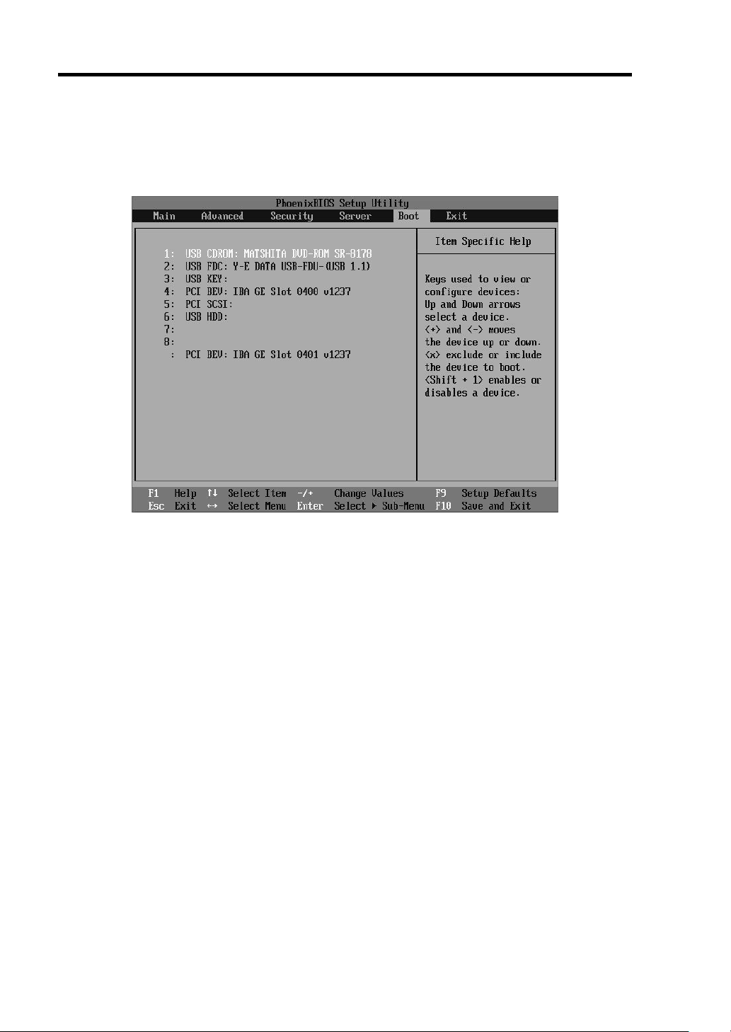
4-24 Configuring Your Server
Boot
Move the cursor onto "Boot" to display the Boot menu. The CPU blade searches for boot devices in
the order set in this menu.
The priority of the boot devices can be changed by using the ↑↑↑↑, ↓↓↓↓, +, and - keys. Move the cursor to
the desired device with the ↑↑↑↑ or ↓↓↓↓ keys and change the priority with the + or - keys.
The boot device priority is factory-set in the following order:
– USB CDROM (optical drive)
– USB FDC (removable device)
– USB Hard Drive
– IBA GE Slot 0400 v1237 (LAN1)
– IBA GE Slot 0401 v1237 (LAN2)
Page 75

Exit
Move the cursor onto "Exit" to display the Exit menu.
Configuring Your Server 4-25
The following describes each option on the Exit menu:
Exit Saving Changes
Select this item to exit SETUP after saving the configuration changes in CMOS (non-volatile
memory). A confirmation screen appears.
If you select "Yes," SETUP exits with the configuration changes saved in CMOS (non-volatile
memory). Then, the CPU blade automatically reboots.
Exit Discarding Changes
Select this item to exit SETUP without saving the configuration changes in CMOS (non-volatile
memory). A confirmation screen appears.
If you select "No," SETUP exits without saving the configuration changes. If you select "Yes,"
SETUP exits with the configuration changes saved in CMOS. Then, the CPU blade automatically
reboots.
Page 76

4-26 Configuring Your Server
Load Setup Defaults
Select this item to return all the values of SETUP to the default values. A confirmation screen
appears.
Select "Yes" to return the values to the default values. Select "No" to return to the Exit menu screen.
IMPORTANT:
The factory-set values of SETUP may be different
from the default values depending on the model of the CPU blade.
Load Custom Defaults
Select this item and press Enter to load the stored custom default values.
Save Custom Defaults
Select this item and press Enter to save the current values as the custom default values. After
saving the values, the Load Custom Defaults menu appears.
Discard Changes
Select this item to return the configuration changes to the previous values. A confirmation screen
appears.
Select "Yes" to discard the configuration changes and return to the previous values.
Save Changes
Select this item to save the configuration changes to CMOS (non-volatile memory) without exiting
SETUP. A confirmation screen appears.
Select "Yes" to save the configuration changes to CMOS (non-volatile memory).
Page 77

Configuring Your Server 4-27
(This page is intentionally left blank.)
Page 78

Chapter 5
Installing the Operating System with Express
Setup
This section describes information on using Express Setup to install and configure the following
operating systems:
Microsoft® Windows® Server 2003 R2 Standard Edition
Microsoft® Windows® Server 2003 R2 Enterprise Edition
To use the server with operating systems other than ones described in this section, contact your
service representative.
IMPORTANT: Before installing the operating system, adjust the
system date and time by using the BIOS setup utility. See Chapter 4
for details.
Page 79
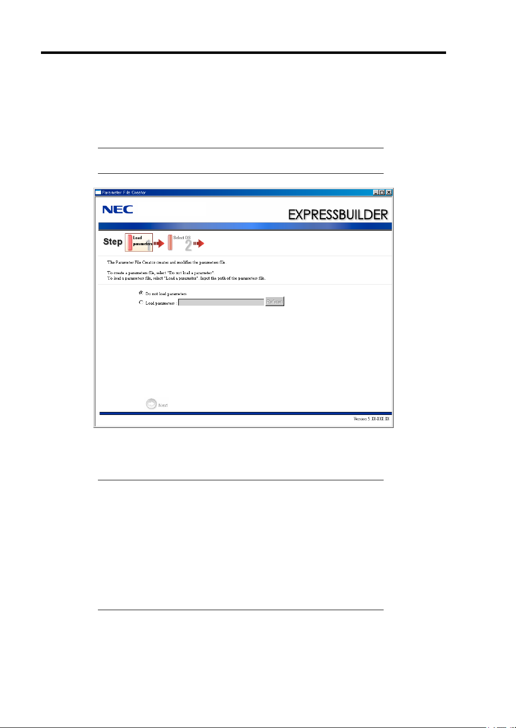
5-2 Installing the Operating System with Express Setup
About Express Setup
Express Setup helps you to install the Windows operating system. It automatically configures the
RAID array and installs the operating system and management software.
IMPORTANT: Using Express Setup erases all data on the hard disk
drive.
You can also use a parameters file with Express Setup that contains parameters for installation.
If you want to set up the server as before, use Express Setup with the parameters file you have
created.
NOTES:
If you want to create a parameters file, have a blank floppy disk
(MS-DOS 1.44MB format) ready.
When using a floppy disk, a USB floppy disk drive is required.
If you want to use the drivers located on the "OEM-Disk for Mass
Storage Device" that ships with optional boards, a parameters file
is required.
You can create a parameters file in advance using "Parameter File
Creator" included in NEC EXPRESSBUILDER.
Page 80

Installing the Operating System with Express Setup 5-3
Microsoft Windows Server 2003
This section explains how to install Microsoft® Windows® Server 2003 by using Express Setup.
NOTES:
Express Setup does not support the installation of Windows Server
x64 Editions. If you need to install it, see Appendix B.
If you install Windows Server 2003 without using Express Setup,
see Appendix B.
Notes on Windows Installation
This section explains the notes on Windows installation.
Review these notes before starting Express Setup.
About the Windows family
This computer supports the following Windows editions:
Microsoft® Windows® Server 2003 R2 Standard Edition / Microsoft® Windows® Server
2003 R2 Enterprise Edition (hereafter referred to as Windows Server 2003)
NOTE: Express Setup does not support the installation of Windows
Server 2003 x64 Editions. If you need to install it, see Appendix B.
To install another operating system, contact your sales or maintenance service representative.
BIOS Settings
Confirm the BIOS settings described in Chapter 4 before installing Windows Server 2003.
Page 81

5-4 Installing the Operating System with Express Setup
Service Pack Which EXPRESSBUILDER Supports
The EXPRESSBUILDER DVD provided with the server supports the following operating system
installation media and Service Packs:
Windows Server 2003 R2 x64 Edition
– Operating system installation media (No Service Pack)
Windows Server 2003 R2
– Operating system installation media (No Service Pack)
Supported Mass Storage Controllers
The NEC EXPRESSBUILDER DVD provided with the server supports the following mass storage
controllers for installation:
NOTE: If you want to install the operating system using a mass
storage controller other than the ones listed below, see "Installing with
the OEM-FD for Mass storage device" and "Installing Optional Mass
Storage Driver" of "Parameter File Creator" in Chapter 6.
Controllers supporting installation of operating system with Express Setup
– N8403-018 FibreChannel Controller
NOTES:
The drivers for the mass storage controllers listed above are stored
on the EXPRESSBUILDER DVD.
If you use a mass storage controller other than the ones listed
above, Express Setup will fail. Refer to the manual provided with
the controller for details.
Page 82

Installing the Operating System with Express Setup 5-5
About the Hardware Components
When you use Express Setup to install Windows Server 2003, make sure you observe the following
instructions before beginning installation:.
Installing on the Mirrored Volume
If you want to install Windows Server 2003 on a volume that is mirrored using "Disk Management,"
invalidate the mirror volume and set it to a basic disk before installation. Validate the mirror volume
again after installation.
You can create, invalidate, or delete the mirror volume by using "Disk Management" in "Computer
Management".
Mounting MO Device
Do not mount an MO device during Windows installation.
About Removable Media
Do not insert removable media, such as DAT, into a mounted device during Windows installation.
Connecting Hard Disk Drive
Only connect the hard disk drive on which you want to install Windows.
If you create multiple logical drives, see "Re-installing the Operating system when multiple logical
drive exist" (Appendix B).
Reinstalling to the hard disk drive which has been upgraded to Dynamic Disk
You cannot reinstall Windows Server 2003 on a partition of a hard disk drive that is a dynamic disk.
If you want to keep the current partition, see Appendix B to reinstall the system.
Page 83

5-6 Installing the Operating System with Express Setup
About the System Partition Size
The system partition size can be calculated from the following formula:
Size necessary to install the system + Paging File Size + Dump File Size
+ Application Size
Size necessary to install the system = 3500MB (Windows Server 2003 R2)
Paging File Size (Recommended) = Mounted Memory Size * 1.5
Dump File Size = Mounted Memory Size + 12MB
Application Size = Required Size
IMPORTANT:
The above paging file size is necessary for collecting the debug
information (memory dump). If a value smaller than the
“Recommended” one is set for the initial size of the paging file,
the correct debug information (memory dump) may not be
collected.
The maximum paging file size which can be set on one partition is
4095MB. If the above paging file size exceeds 4095MB, specify
4095MB for the paging file size.
The maximum dump file size for a system with more than 2GB of
memory is '2048MB + 12MB.'
If you need to install other applications, add the hard disk space
required for those applications.
For example, if the mounted memory size is 512MB, the partition size calculated by the above
formula is as follows:
3500MB + (512MB * 1.5) + (512MB + 12MB) + Application Size
= 4792MB + Application Size
If the recommended partition size of a system as described in the formula above exceeds the
capacity of the hard disk drive, the paging file size of the partition can be stored on a separate disk.
1.
Calculate the "Size required for installation + Paging file size" with the formula described
above.
2.
See Chapter 5 to set debugging information (equivalent to the dump file size) to be written
to a separate disk.
If the disk does not have enough free space for the dump file size to be written, install an
additional disk.
Installing the Service Pack
When installing Windows Server 2003 R2, it is not necessary to install Service Pack 1.
Page 84

Installing the Operating System with Express Setup 5-7
Accept Software License Agreement
FLOW OF SETUP
The following flow chart illustrates the setup procedures for Express Setup:
Remove the floppy disk and CD/DVD-ROM
from the drives
Loading parameters (Step 2)
Next
Select the operating system (Step 3)
Next
RAID configuration (Step 4)
Next
Windows Confirm Setting / Input
(Steps 5 to 10)
Next
Save parameters (Step 11)
Next
Start Express Setup (Step 12)
Perform
RAID Configuration
Create the OS partition / format
Copying Windows drivers
↓
Copying selected applications
Skip
Insert Windows CD-ROM
Install OS Automatically
↓
Log on Automatically
The installation is complete.
: Process that requires user input
: Process that proceeds automatically
Page 85

5-8 Installing the Operating System with Express Setup
INSTALLING WINDOWS SERVER 2003
Express Setup proceeds by selecting or inputting parameters in the wizard. You can also save the
parameters to a floppy disk as a parameters file.
1.
Turn on peripheral devices and then turn on the server.
2.
Insert the NEC EXPRESSBUILDER DVD into the optical disc drive of the server.
3.
Press the RESET switch or press
EXPRESSBUILDER DVD.
The system boots from the DVD-ROM and NEC EXPRESSBUILDER starts.
Select "OS installation *** default ***" from the boot selection menu. If you do not press
any key, "OS installation" is selected automatically.
The Top menu appears.
4.
Select [Perform the Express setup] from the Top menu and click [Next].
Ctrl, Alt
, and
Delete
to boot from the NEC
Page 86

Installing the Operating System with Express Setup 5-9
5.
The [Load parameters] steps are displayed.
[Do not load parameters]
(1) Select [Do not load parameters] if you do not have a parameters file.
(2) Click [Next].
NOTE:
[Load parameters]
(1) Insert the floppy disk containing the parameters file.
(2) Select [Load parameters] and enter the file path of the parameters file in the text box.
(3) Click [Next].
If a floppy disk drive is not connected, select this item.
Page 87

5-10 Installing the Operating System with Express Setup
6.
Select the operating system to install.
Select [Install the Windows (32bit editions)] from the menu and click [Next].
7.
Enter the logical drive settings.
The [Enter RAID settings] steps are displayed. Confirm the parameters, modify if
necessary, and then click [Next].
NOTES:
You can use only the physical devices that have the same model
number to configure a logical drive.
If the process does not complete normally, the driver may not be
stored in EXPRESSBUILDER. Refer to "Optional Board
Supported by NEC EXPRESSBUILDER" described earlier in this
chapter.
Page 88
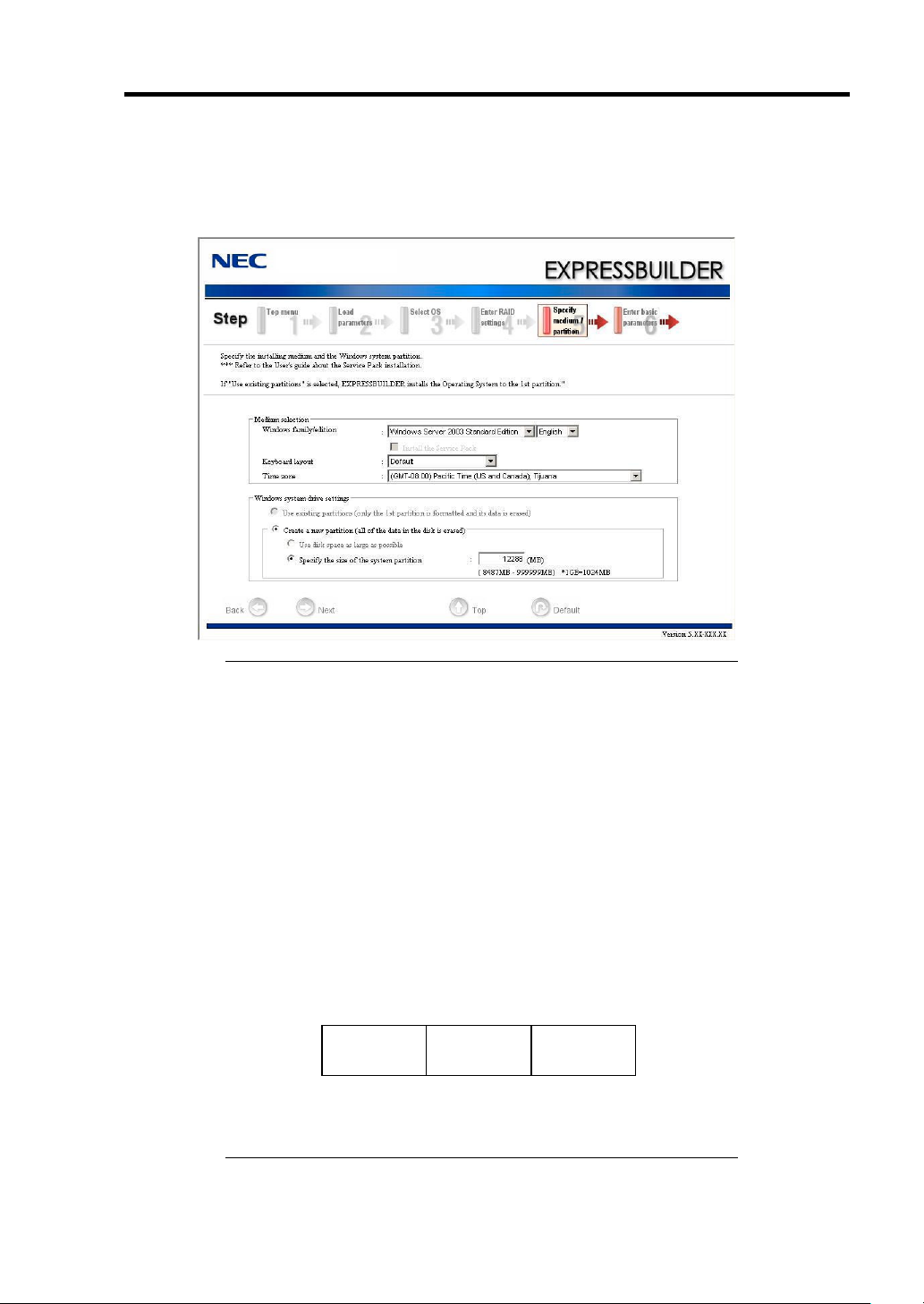
Installing the Operating System with Express Setup 5-11
8.
Specify the installation medium and the Windows system partition.
The [Specify medium / Partition] steps are displayed. Confirm the parameters, modify if
necessary, and then click [Next].
IMPORTANT:
About partition size
– Specify a partition size larger than the required minimum size
for operating system installation.
– Do not specify a partition size larger than the capacity of the
connected hard disk drive.
– You cannot specify a partition size larger than 2,097,152MB
(2TB) for a RAID system.
If you select "Create a new partition" in "Windows system drive
settings," the contents of the hard disk will be deleted.
If "Use existing partitions" is selected, EXPRESSBUILDER
installs the operating system to the first partition (the first partition
is deleted). The data in the other partitions is retained if the system
has two or more partitions (see the figure below).
First
Partition
Deleted
You cannot reinstall the system if the existing partition is upgraded
Second
Partition
Retained
Third
Partition
Retained
to a dynamic disk. Do not select "Use existing partitions" in
"Windows system drive settings."
Page 89

5-12 Installing the Operating System with Express Setup
9.
Enter the user information and client license mode.
The [Enter basic parameters] steps are displayed. Confirm the parameters, modify if
necessary, and then click [Next].
NOTE:
“
password.”
10.
Enter the network protocol settings.
The [Enter Network Protocol] steps are displayed. Confirm the parameters, modify if
necessary, and then click [Next].
Even if you do not enter an Administrator password,
” is displayed in “Administrator password” and “Confirm
Page 90

Installing the Operating System with Express Setup 5-13
11.
Enter the domain or workgroup name.
The [Enter domain account] steps are displayed. Confirm the parameters, modify if
necessary, and then click [Next].
12.
Select the Windows components to install.
The [Select Windows components] steps are displayed. Confirm the parameters, modify if
necessary, and then click [Next].
Page 91

5-14 Installing the Operating System with Express Setup
13.
Select the applications to install.
The [Select applications] steps are displayed. Confirm the parameters, modify if necessary,
and then click [Next].
14.
Save the parameters.
The [Save parameters] steps are displayed.
If you want to save the parameters, insert a formatted floppy disk.
Select [Save parameters], enter the file path of the parameters file in the text box, and
click [Next].
If not, select [Do not save parameters].
Page 92

Installing the Operating System with Express Setup 5-15
15.
Express Setup will start when you click [Perform] in the [Start Express setup] step.
16.
Copy optional Mass Storage Driver.
If you need to install an optional mass storage driver, a message will appear.
Insert the CD-ROM or floppy disk containing the mass storage driver and proceed
according to the messages.
17.
Remove the NEC EXPRESSBUILDER DVD from the optical disc drive according to the
message.
If you proceed with setup by using a parameters file, remove the floppy disk from the
floppy disk drive.
Insert the Windows Server 2003 CD-ROM into the optical disc drive.
The [Agree Software License Agreement] screen appears.
Page 93

5-16 Installing the Operating System with Express Setup
18.
Read the contents carefully and click [Yes] if you agree. If you do not agree, click [No].
IMPORTANT:
If you do not agree to this license, setup terminates and Windows
Server 2003 will not be installed.
If the "NetWare Gateway (and Client) Service" is specified to
install, a window to specify settings for the "NetWare Gateway
(and Client) Service" pops up on the first logon. Specify the
appropriate values.
Windows Server 2003 and selected applications will be installed automatically and the
server will reboot several times.
After rebooting, it logs on to the system automatically.
19.
If you install Microsoft Windows Server 2003 R2, insert the Microsoft Windows Server
2003 R2 Standard Edition DISC 2 or Microsoft Windows Server 2003 R2 Enterprise
Edition DISC 2 into the optical disc drive after the operating system installation.
When the installation finishes, remove the Microsoft Windows Server 2003 R2 Standard Edition
DISC 2 or Microsoft Windows Server 2003 R2 Enterprise Edition DISC 2 from the optical disc
drive and restart the system.
Express Setup is complete.
Page 94

Installing the Operating System with Express Setup 5-17
INSTALLING AND SETTING DEVICE DRIVERS
Follow these steps to install and configure the device drivers.
PROSet
NOTE:
with administrator privileges. Operation by [Remote Desktop
Connection] is prohibited.
When viewing the adapter teaming settings in the adapter properties
dialog box, click [Cancel] if you have not made any changes. Clicking
[OK] may cause temporary loss of network connectivity.
PROSet is a utility that configures and monitors the functions of the network adapter.
PROSet provides the following functions:
Detailed adapter information.
Diagnosis by using loopback and packet send tests.
Teaming configuration.
Configuring several network adapters as one team provides a fault-tolerant networking environment
and enhances throughput between the switches.
PROSet is necessary to utilize these features.
Follow the procedure below to install PROSet:
1.
Insert the NEC EXPRESSBUILDER DVD into the optical disc drive.
If the autorun menu appears, close the menu screen.
2.
Open [Windows Explorer].
All of the following operations must be performed by a user
Click [Start], click [Programs], click [Accessories], and click [Windows Explorer].
3.
Run "dxsetup.exe" in the following directory:
\001\win\winnt\dotnet\ns41s\proset\2kxpws03
The [Intel(R) PROSet - Install Shield Wizard] starts.
4.
Click [Next].
5.
In the [License Agreement] window, select [I Accept the terms in the license agreement].
6.
Click [Next].
7.
Select [Complete] and click [Next].
8.
Click [Install] to begin the installation and then click [Finish] in [InstallShield Wizard
Completed].
9.
Restart the system.
Page 95

5-18 Installing the Operating System with Express Setup
Network Driver
Configure the settings of the network driver.
The standard network driver will be installed automatically, but the link speed and Duplex mode
need to be specified manually.
[When PROSet is not installed]
1.
Open [Local Area Connection Properties].
* For the standard start menu:
1. Click [Start], click [Control Panel], click [Network Connections], and click [Local
Area Connection].
* For the classic start menu
1. Click Start, click [Settings], and click [Network Connections].
The [Network Connections] dialog box appears.
2. Right-click [Local Area Connection] and click [Properties].
2.
Click [Configure].
The properties dialog box for the network adapter appears.
3.
Click the [Advanced] tab and specify [Link Speed & Duplex] values that match the hub.
4.
Click [OK].
[When PROSet is installed]
1.
Open [Intel(R) PROSet].
* For the standard start menu:
Click [Start], click [Control Panel], click [Administrative Tools], and click
[Computer Management]. Double-click the [(Network Adapter Name)] in the
Network Adapter list.
* For the classic start menu:
1. Click Start, click [Settings], and click [Control Panel].
2. Click [Administrative Tools].
3. Click [Computer Management] and double-click the [(Network Adapter Name)] in
the Network Adapter list.
2.
Click the [Link] tab and specify [Speed and Duplex] values that match the hub.
3.
Click [Apply] and then click [OK].
Also, add or delete any protocols and services if necessary.
Page 96

Installing the Operating System with Express Setup 5-19
NOTE:
Services]. [Network Monitor] can monitor the frame (or packet) that
the computer sends or receives. This tool is valuable when analyzing
network issues. For information on how to install the tool, see "Setting
for Solving Problems" described later in this chapter.
It is recommend to add [Network Monitor] in [Adding
Optional Network Board Driver
If you want to use the optional Network Board (N8403-017/020), install the driver stored on the
NEC EXPRESSBUILDER DVD.
The driver is in the following directory:
"\001\win\winnt\dotnet\ns41s\pro1000\ws03xp2k"
Refer to the installation procedure described in the section "Installation of the Optional Network
Board Driver."
Installation of the Optional Network Board Driver
Open [Device Manager].
1.
2.
Click [Network adapters] and double-click [(Network Adapter Name)].
[(Network Adapter Name) Properties] appears.
NOTE:
All other names are for the Optional Network Board.
3.
Click the [Driver] tab and click [Update Driver...]. The [Hardware Update Wizard]
appears.
4.
Select the [Install from a list or specific location (Advanced)] radio button and click
[Next].
5.
Select the [Search for the best driver in these locations] radio button and check the
[Search removable media (floppy, CD-ROM...)] check box.
6.
Check the [Include this location in the search] check box and specify:
"\001\win\winnt\dotnet\ns41s\pro1000\ws03xp2k"
Then, click [Next].
7.
Click [Finish].
[(Intel(R) PRO/1000...)] is the name of the onboard adapter.
Page 97

5-20 Installing the Operating System with Express Setup
Adapter Fault Tolerance (AFT)/Adaptive Load Balancing (ALB)
Adapter Fault Tolerance (AFT) is a feature that places more than one LAN controller on the same
LAN (same segment), and automatically switches the process of the primary controller to the
backup controller when any trouble occurs on the primary.
Adaptive Load Balancing (ALB) is a feature that connects more than one LAN controller to
the same hub and enhances the throughput by operating packet transmission from the server.
This feature includes the AFT feature.
IMPORTANT:
AFT/ALB configuration must be done after installing the drivers
and restarting the system.
All adapters specified as a group in Adapter Teaming must exist on
the same LAN. If they are connected to separate switches, they
will not work normally.
The adapters specified as a group for Adaptive Load Balancing
(ALB) can only be connected to the switching hub.
Before replacing the motherboard or option network card, make
sure to remove the adapter team. Recreate the adapter team after
the replacement is complete.
If you want to use the AFT/ALB features, follow the procedure below:
1.
Open [Intel (R) PROSet].
Click [Start], click [Control Panel], click [Administrative Tools], and click
[Computer Management]. Double-click the [(Network Adapter Name)] in the
Network Adapter list.
2.
Select the [Teaming] tab, check [Team with other adapters], and click [New Team...].
The [New Team Wizard] dialog box appears. Click [Next].
* Specify a name for the team if necessary.
3.
Select the adapters to include in the team.
4.
Select "Adapter Fault Tolerance" or "Adaptive Load Balancing" and click [Next].
5.
Click [Finish].
Page 98

Installing the Operating System with Express Setup 5-21
6.
If it is necessary to set the adapter priority setting, refer to the following step.
If it is not necessary, go to Step 7.
1. Click the [Settings] tab in [TEAM:xxx #yy Properties].
2. Click [Modify Team].
3. Select the adapter [Intel(R)PRO/1000....] and click [Set Primary] or [Set Secondary].
4. Click [OK].
5. In [TEAM:xxx #yy Properties], the priority setting will appear in the list.
6. Click [OK].
7.
In the [Intel (R) PROSet for Wired Connections] dialog box, click [OK].
8.
Restart the system.
Page 99

5-22 Installing the Operating System with Express Setup
Graphics Accelerator Driver
The driver for the standard graphics accelerator will be installed automatically. The following
procedure describes how to install it manually::
1.
Insert the NEC EXPRESSBUILDER DVD into the optical disc drive.
If the autorun menu appears, close the menu screen.
2.
Click [Start], click [Programs], click [Accessories], and click [Windows Explorer].
3.
Run "setup.exe" in the following directory:
\001\win\winnt\dotnet\video\matrox\setup.exe
4.
Follow the messages to continue the installation.
If the message "Digital Signature could not been found" appears, select [Yes] to continue.
5.
Remove the NEC EXPRESSBUILDER DVD from the optical disc drive and restart the
system.
Installing N8403-018 FibreChannel Controller
If you use the FibreChannel Controller (N8403-018), update your system with the NEC
EXPRESSBUILDER DVD.
The FibreChannel Controller driver will be installed automatically.
Page 100

Installing the Operating System with Express Setup 5-23
Available switch options for Windows Server 2003 Boot.ini file
Many different switche options are available for the Boot.ini file.
For the available switch options, refer to the following information:
Microsoft Knowledge Base - Article ID: 833721
"Available switch options for the Windows XP and the Windows Server 2003 Boot.ini
files"
If your system has in excess of 4GB of memory installed, adding the /PAE switch in the Boot.ini file
will enable the system to address over 4GB of memory.
However, the Microsoft operating systems which support the /PAE switch option are limited.
Refer to the following article in Microsoft Knowledge Base to check the supported products:
Microsoft Knowledge Base - Article ID: 291988
"A description of the 4GB RAM tuning feature and the Physical Address Extension
switch"
on the following example shows how to add the /PAE switch to the Boot.ini file:
1.
Click [Start], click [Settings], and then click [Control Panel].
2.
In [Control Panel], double-click [System].
3.
Click the [Advanced] tab and then click [Settings] under [Setup and Recovery].
4.
Under [System Setup], click [Edit] to open [Boot.ini].
5.
Add "/PAE" to the [Operating Systems] section in the [Boot.ini] file and then save it.
<Example of Boot.ini file>
[boot loader]
timeout=30
default=multi(0)disk(0)rdisk(0)partition(2)\WINDOWS
[operating systems]
multi(0)disk(0)rdisk(0)partition(2)\WINDOWS="Windows Server 2003" /fastdetect
multi(0)disk(0)rdisk(0)partition(2)\WINDOWS="Windows Server 2003, PAE" /fastdetect
/PAE
C:\CMDCONS\BOOTSECT.DAT="Microsoft Windows Recovery Console" /cmdcons
NOTE:
If you choose one of the items in the "Default operating
system" drop-down list box in [Setup and Recovery], you can start the
system automatically with the switch you specified.
 Loading...