

Page 1
製品をご使用になる前に必ず本書をお読みください。
本書は熟読の上、大切に保管してください。
Make sure you read this manual before using the product.
After reading this manual, store it in a safe place.
本書は製品とともに大切に保管してください
Keep this manual in a safe place.
N8403-019
ディスクアレイコントローラユーザーズガイド
Disk Array Controller User's Guide
Page 2

商標について
Microsoft とそのロゴおよび、Windows、MS、MS-DOS は米国 Microsoft 社の米国およびその他の国における登録商標で
す。
Engenio Information Technologies, Inc.とそのロゴおよび、MegaRAID、WebBIOS、MegaRAID Storage Manager
米国 LSI Logic 社の登録商標です。
ESMPRO®は、日本電気株式会社の商標です。
TM
は、
Trademarks
Microsoft, its logo, Windows, Windows Server and MS-DOS are worldwide registered trademarks of Microsoft
Corporation of the U.S.A.
Engenio Information Technologies, Inc., its logo, MegaRAID, WebBIOS, and MegaRAID Storage ManagerTM are
registered trademarks of LSI Logic Inc. of the U.S.A.
NEC ESMPRO and NEC EXPRESSBUILDER are registered trademarks of NEC Corporation.
All company names and product names mentioned herein are trademarks or registered trademarks of their respective
companies.
ご注意
(1) 本書の内容の一部または全部を無断転載することは禁止されています。
(2) 本書の内容に関しては将来予告なしに変更することがあります。
(3) NECの許可なく複製・改変などを行うことはできません。
(4) 本書は内容について万全を期して作成いたしましたが、万一ご不審な点や誤り、記載もれなどお気づきのことがあ
りましたら、お買い求めの販売店にご連絡ください。
(5) 運用した結果の影響については(4)項にかかわらず責任を負いかねますのでご了承ください。
(6) 落丁、乱丁本はお取り替えいたします。
Notes:
(1) No part of this manual may be reproduced in any form without the prior written permission of NEC Corporation.
(2) The contents of this manual may be revised without prior notice.
(3) The contents of this manual shall not be copied or altered without the prior written permission of NEC Corporation.
(4) All efforts have been made to ensure the accuracy of all information in this manual. If you notice any part unclear,
incorrect, or omitted in this manual, contact the sales agent where you purchased this product.
(5) NEC assumes no liability arising from the use of this product, nor any liability for incidental or consequential
damages arising from the use of this manual regardless of Item (4).
(6) If you find any missing pages or pages out of order in this manual, please contact your dealer for a replacement.
Page 3

まえがき
Preface
このたびは、ディスクアレイコントローラをお買い上げいただきまことにありがとうございます。
本書は、N8403-019 ディスクアレイコントローラ(内蔵 SAS HDD 用)(以降「本製品」と呼ぶ)を正しく、
安全に設置、使用するための手引きです。本製品を取り扱う前に必ずお読みください。また、本製品を使用
する上でわからないこと、不具合が起きたときにもぜひご利用ください。本書は、必要な時にすぐに参照で
きるように必ずお手元に保管してください。
本製品を取り付ける本体装置の取り扱いについての説明は、本体装置のユーザーズガイドを参照してくださ
い。また、本製品を取り扱う前に「使用上のご注意」を必ずお読みください。
なお、本書は和英併記となっております。日本語での説明は i ページから 63 ページを、英語での説明は i ペー
ジから xvi ページおよび、64 ページから 125 ページを参照してください。
Congratulations on your purchase of the Disk Array Controller.
The User‟s Guide describes how to install and use the N8403-019 Disk Array Controller (Internal SAS HDD)
correctly and safely. Read this guide thoroughly before using the disk array controller. In addition, refer to this
manual when a problem occurs. Always keep this manual handy for quick reference when necessary.
For the server in which the disk array controller is installed, refer to the User‟s Guide of the server. Read
"Notes on Use" carefully before handling the disk array controller.
This User's Guide is written in both Japanese and English. For Japanese, refer to pages i to 63. For English,
refer to pages i to xvi and 64 to 125.
Page 4
ii
人が死亡する、または重傷を負うおそれがあることを示します。
WARNING
Indicates the presence of a hazard that may result in death or serious
personal injury.
火傷やけがなどを負うおそれや物的損害を負うおそれがあることを示しま
す。
CAUTION
Indicates the presence of a hazard that may cause minor personal injury,
including burns, or property damage.
このユーザーズガイドは、必要なときすぐに参照できるよう、お手元に置いておくようにしてください。
Keep this User's Guide handy for quick reference when necessary.
「使用上のご注意」を必ずお読みください。
Be sure to read this section carefully.
使用上のご注意 ~必ずお読みください~
NOTES ON USE - Always read the Notes -
本製品を安全に正しくご使用になるために必要な情報が記載されています。
The following includes information necessary for proper and safe operation of the product.
安全に関わる表示について
SAFETY INDICATIONS
本書では、安全にお使いいただくためにいろいろな絵表示をしています。表示を無視し、誤った取り扱いを
することによって生じる内容を次のように区分しています。内容をよく理解してから本文をお読みください。
In the User‟s Guide, "WARNING" or "CAUTION" is used to indicate a degree of danger. These terms are
defined as follows:
Page 5
iii
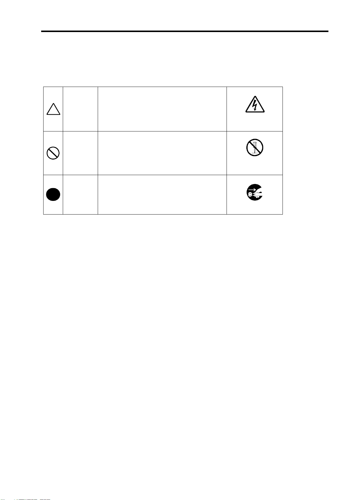
注意の喚起
Attention
この記号は危険が発生するおそれがあることを表し
ます。記号の中の絵表示は危険の内容を図案化したも
のです。
This symbol indicates the presence of a hazard.
An image in the symbol illustrates the hazard type.
(例) (Example)
(感電注意)
Precaution against
electric shock
行為の禁止
Prohibited
Action
この記号は行為の禁止を表します。記号の中や近くの
絵表示は、してはならない行為の内容を図案化したも
のです。
This symbol indicates prohibited actions. An image
in the symbol illustrates a particular prohibited action.
(例) (Example)
(分解禁止)
Prohibition of
disassembly
行為の強制
Mandatory
Action
この記号は行為の強制を表します。記号の中の絵表示
は、しなければならない行為の内容を図案化したもの
です。危険を避けるためにはこの行為が必要です。
This symbol indicates mandatory actions. An image
in the symbol illustrates a mandatory action to avoid
a particular hazard.
(例) (Example)
(プラグを抜け)
Unplug the power cord!
危険に対する注意・表示は次の3種類の記号を使って表しています。それぞれの記号は次のような意味を持
つものとして定義されています。
Precautions against hazards are presented with the following symbols. The individual symbols are defined as
follows:
Page 6
iv
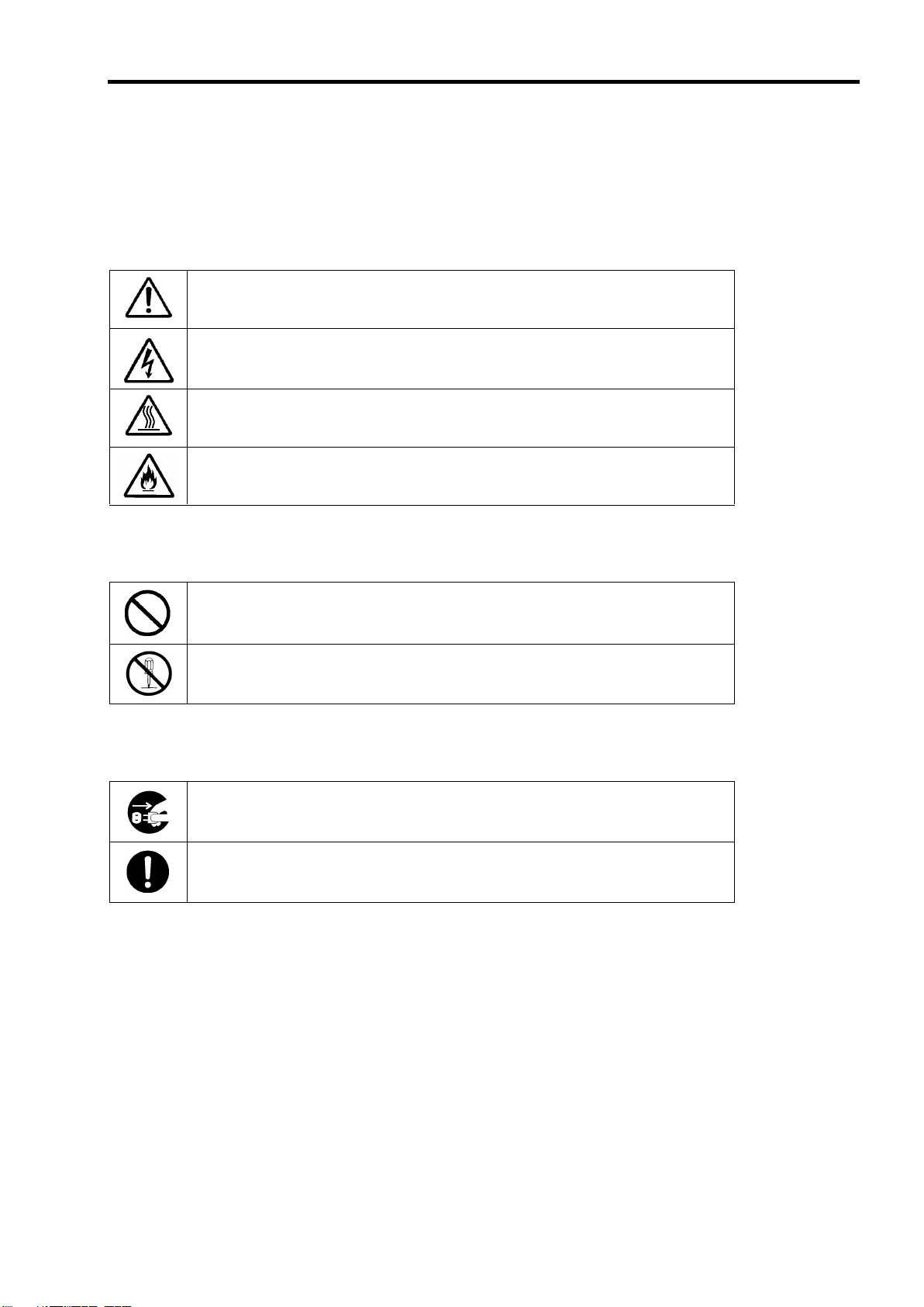
特定しない一般的な注意・警告を示します。
Indicates a general notice or warning that cannot be specifically identified.
感電のおそれがあることを示します。
Indicates that improper use may cause an electric shock.
高温による障害を負うおそれがあることを示します。
Indicates that improper use may cause personal injury.
発煙または発火のおそれがあることを示します。
Indicates that improper use may cause fumes or fire.
特定しない一般的な禁止を示します。
Indicates a general prohibited action that cannot be specifically identified.
分解・修理しないでください。感電や火災のおそれがあります。
Do not disassemble, repair, or modify the server. Otherwise, an electric shock or fire
may be caused.
電源コードをコンセントから抜いてください。火災や感電のおそれがあります。
Unplug the power cord of the server. Otherwise, an electric shock or fire may be
caused.
特定しない一般的な使用者の行為を指示します。説明に従った操作をしてください。
Indicates a mandatory action that cannot be specifically identified. Make sure to
follow the instruction.
本書で使用する記号とその内容
Symbols Used in This Manual and Warning Labels
注意の喚起
Attentions
行為の禁止
Prohibited Actions
行為の強制
Mandatory Action
Page 7
安全上のご注意
WARNING
人命に関わる業務や高度な信頼性を必要とする業務には使用しない
Do not use the product in life-critical applications or applications requiring
high reliability.
本製品は、医療機器、原子力設備や機器、航空宇宙機器、輸送設備や機器など人命
に関わる設備や機器、および高度な信頼性を必要とする設備や機器などへの組み込
みや制御等の使用は意図されておりません。これら設備や機器、制御システムなど
に本製品を使用され、人身事故、財産損害などが生じても、当社はいかなる責任も
負いかねます。
The product is not intended for integration with or control of facilities or equipment
that may affect human life or that require a high degree of reliability, such as
medical equipment, nuclear power facilities or instruments, aerospace instruments,
transportation facilities or instruments. NEC does not assume any liability for
accidents resulting in injury or death, or for any damages to property that may occur
as a result of using the product in such facilities, equipment, or control systems.
煙や異臭・異音がしたまま使用しない
Do not use the server if any smoke, odor, or noise is present.
万一、煙、異臭、異音などが生じた場合は、ただちに本体装置の電源をOFFにして
電源コードをACコンセントから抜いてください。その後、お買い求めの販売店また
は保守サービス会社にご連絡ください。そのまま使用すると火災の原因となります。
If smoke, odor, or noise is present, immediately turn off the server and disconnect
the power plug from the AC outlet, then contact your service representative. Using
the server in such conditions may cause a fire.
針金や金属片を差し込まない
Keep needles or metal objects away from the server.
通気孔やカートリッジ挿入口から金属片や針金などの異物を差し込まないでくださ
い。感電するおそれがあります。
Do not insert needles or metal objects into ventilation holes or cartridge slots of the
server. Doing so may cause an electric shock.
Safety Indications
本製品を安全にお使いいただくために、ここで説明する注意事項をよく読んでご理解していただき、安全に
ご活用ください。記号の説明については巻頭の『安全にかかわる表示について』の説明を参照してください。
This section provides notes on using your product safely. Read this section carefully to ensure proper and
safe use of the product. For symbols, see "SAFETY INDICATIONS" provided earlier.
<全般的な注意事項>
General
v
Page 8
vi
CAUTION
装置内に水や異物を入れない
Keep water or foreign matter away from the server.
装置内に水などの液体、ピンやクリップなどの異物を入れないでください。火災や
感電、故障の原因となります。もし入ってしまったときは、すぐに本体装置の電源
をOFFにして電源コードをACコンセントから抜いてください。分解しないで販売店
または保守サービス会社に連絡してください。
Do not let any form of liquid (water etc.) or foreign matter (e.g., pins or paper clips)
enter the server. Failure to follow this warning may cause an electric shock, a fire, or
a failure of the server. When such things accidentally enter the server, immediately
turn off the power and disconnect the power plug from the AC outlet. Do not
disassemble the server. Contact your service representative.
Page 9
<電源・電源コードに関する注意事項>
CAUTION
電源がONのまま取り付け・取り外しをしない
Disconnect the power cord(s) before installing or removing the product
in/from the server.
本体装置への取り付け・取り外しの際や、周辺機器との接続の際は必ず主電源に接
続している電源コードをACコンセントから抜いてください。電源コードがACコンセ
ントに接続されたまま取り付け・取り外しや接続をすると感電するおそれがありま
す。
Make sure to power off the server and disconnect the power cord(s) from a power
outlet before installing/removing the product in/from the server, or connecting with
the peripheral devices. All voltage is removed only when the power cords are
unplugged.
破損したケーブルを使用しない
Do not use a damaged cable.
ケーブルを接続する前にコネクタが破損していたり、コネクタピンが曲がっていた
り、汚れたりしていないことを確認してください。破損や曲がっているコネクタお
よび汚れたコネクタを使用するとショートにより火災を引き起こすおそれがありま
す。
Check the cable condition before connection. Using a damaged connector, bent
connector pin, or dirty connector may cause a fire due to a short-circuit.
ぬれた手で電源コードをもたない
Do not hold the power plug with wet hands.
本製品の取り付け・取り外しの場合は、ぬれた手で本体装置の電源コードの抜き差
しをしないでください。感電するおそれがあります。
Do not disconnect/connect the plug while your hands are wet. Failure to follow this
warning may cause an electric shock.
電源コードのケーブル部を持って引き抜かない
Do not pull the cable when disconnecting the power cord.
本体装置の電源コードの抜き差しは、ケーブル部を持って引っ張らないでください。
ケーブルが傷み、感電や火災の原因となります。
When disconnecting the power cord from the server, hold the plug and pull it straight
out. Pulling the cord out by the cable portion could damage the cable, resulting in an
electrical shock hazard or a fire.
Power Supply and Power Cord Use
vii
Page 10
viii
CAUTION
プラグを差し込んだままインタフェースケーブルの取り付けや取り外しをしない
Do not connect any interface cable with the power cord of the server plugged
into a power source.
インタフェースケーブルの取り付け/取り外しは本体装置の電源コードをコンセン
トから抜いて行ってください。たとえ電源をOFFにしても電源コードを接続したま
まケーブルやコネクタに触ると感電したり、ショートによる火災を起こしたりする
ことがあります。
Make sure to power off the server and unplug the power cord from a power outlet
before connecting/disconnecting any interface cable to/from the server. If the
server is off-powered but its power cord is plugged into a power source, touching a
cable or connector may cause an electric shock or a fire due to a short circuit.
指定以外のインタフェースケーブルを使用しない
Do not use an unauthorized interface cable.
インタフェースケーブルは、NECが指定するものを使用し、接続する装置やコネク
タを確認した上で接続してください。指定以外のケーブルを使用したり、接続先を
誤ったりすると、ショートにより火災を起こすことがあります。
また、インタフェースケーブルの取り扱いや接続について次の注意をお守りくださ
い。
ケーブルを踏まない。
ケーブルの上にものを載せない。
ケーブルの接続がゆるんだまま使用しない。
破損したケーブルを使用しない。
破損したケーブルコネクタを使用しない。
ネジ止めなどのロックを確実に行ってください。
Use only interface cables authorized by NEC and locate a proper device and
connector before connecting a cable. Using an unauthorized cable or connecting a
cable to an improper destination may cause a short circuit, resulting in a fire.
Also, observe the following notes on using and connecting an interface cable:
Do not step on the cable.
Do not place any object on the cable.
Do not use the server with loose cable connections.
Do not use any damaged cable connector.
Make sure the cable is securely locked with a screw.
<設置・移動・保管・接続に関する注意事項>
Installation, Relocation, Storage, and Connection
Page 11
ix
CAUTION
腐食性ガスの存在する環境で使用または保管しない
Do not use or store the product in a place where corrosive gases exist.
腐食性ガス(二酸化硫黄、硫化水素、二酸化窒素、塩素、アンモニア、オゾンなど)
の存在する環境に設置し、使用しないでください。
また、ほこりや空気中に腐食を促進する成分(塩化ナトリウムや硫黄など)や導電
性の金属などが含まれている環境へも設置しないでください。装置内部のプリント
板が腐食し、故障および発煙・発火の原因となるおそれがあります。もしご使用の
環境で上記の疑いがある場合は、販売店または保守サービス会社にご相談ください。
Make sure not to locate or use the server in a place where corrosive gases (sulfur
dioxide, hydrogen sulfide, nitrogen dioxide, chlorine, ammonia, ozone, etc) exist.
Also, do not install it in an environment where the air (or dust) includes components
accelerating corrosion (e.g., sulfur, sodium chloride) or conductive metals. There is
a risk of a fire due to corrosion and shorts of the internal printed circuit board.
Consult with your service representative for the appropriate location for the server.
高温注意
Avoid installation in extreme temperature conditions.
本体装置の電源をOFFにした直後は、内蔵型のハードディスクドライブなどをはじ
め装置内の部品が高温になっています。十分に冷めたことを確認してから取り付け/
取り外しを行ってください。
Immediately after the server is powered off, its internal components such as hard
disk drives are very hot. Leave the server until its internal components fully cool
down before installing/removing any component.
Page 12
x
WARNING
自分で分解・修理・改造はしない
Do not disassemble, repair, or alter the server.
本製品の分解や、修理・改造は絶対にしないでください。装置が正常に動作しなく
なるばかりでなく、感電や火災の危険があります。
Never attempt to disassemble, repair, or alter the product. Failure to follow this
instruction may cause an electric shock or fire as well as malfunctions of the
product.
プラグを差し込んだまま取り扱わない
Disconnect the power plug before opening the server.
お手入れは、本体装置の電源をOFFにして、電源コードをACコンセントから抜いて
ください。たとえ電源をOFFにしても、電源コードを接続したまま装置内の部品に
触ると感電するおそれがあります。
Make sure to power off the server and disconnect the power plug from the AC outlet
before opening the server. Touching any internal device of the server with its power
cord connected to a power source may cause an electric shock even if the server is
off-powered.
CAUTION
中途半端に取り付けない
Make sure to complete installation.
DCケーブルやインタフェースケーブルは確実に取り付けてください。中途半端に取
り付けると接触不良を起こし、発煙や発火の原因となるおそれがあります。
Always connect the DC cable and/or interface cable firmly. An incompletely
connected cable may cause a contact failure, resulting in a fire.
<お手入れに関する注意事項>
Cleaning and Working with the Product
Page 13
<運用中の注意事項>
CAUTION
雷がなったら触らない
Avoid contact with the server during thunderstorms.
雷が鳴りだしたら、本製品内蔵の本体装置には、触れないでください。感電するお
それがあります。
Disconnect the power plug from the outlet when a thunderstorm is approaching.
If it starts thundering before you disconnect the power plug, do not touch any part of
the server containing the product. Failure to follow this warning may cause an
electric shock.
ペットを近づけない
Keep animals away from the server.
本製品が内蔵された本体装置にペットなどの生き物を近づけないでください。排泄
物や体毛が装置内部に入って火災や感電の原因となります。
Keep animals away from the server containing the product.
Animal waste and hair may enter the server and cause a fire or electric shock.
近くで携帯電話やPHSを使用しない
Do not use a cellular phone or a pager around the server.
本製品が内蔵された本体装置のそばでは、携帯電話やPHS、ポケットベルの電源を
OFFにしてください。電波による誤動作の原因となります。
Turn off cellular phones and pagers near the server containing the product. Radio
interference may cause malfunctions of the server.
During Operation
xi
Page 14
xii
電波障害自主規制について
この装置は、情報処理装置等電波障害自主規制協議会(VCCI)の基準に基づくクラス A 情報
技術装置です。この装置を家庭環境で使用すると電波妨害を引き起こすことがあります。この
場合には使用者が適切な対策を講ずるよう要求されることがあります。
使用上のご注意 ~装置を正しく動作させるために~
本製品を使用するときに注意していただきたいことを次に示します。これらの注意を無視して、本製品を使
用した場合、資産(データやその他の装置)が破壊されるおそれがありますので必ずお守りください。
本製品は Express5800 ブレードサーバに Serial Attached SCSI(SAS)機器を接続するためのディスクア
レイコントローラです。他の目的では使用しないでください。
本製品は大変デリケートな電子装置です。本製品を取り扱う前に、本体装置の金属フレーム部分などに触
れて身体の静電気を逃がしてください。本製品の取り扱いは端の部分を持ち、表面の部品やコネクタと接
続する部分には触れないようにしてください。また、本製品を落としたり、ぶつけたりしないでください。
本製品には、同一規格のハードディスクドライブ(以降「HDD」と呼ぶ)を接続してください。
本製品に接続可能な本体装置、HDD については、お買い求めの販売店にお問い合わせください。
本製品は、他のメザニンカード(LAN コントローラ、SCSIコントローラ等)の混在使用を制限している場
合があります。本製品を他のメザニンカードと混在してご使用になる場合は、混在が可能かどうかお買い
求めの販売店にご確認ください。
Page 15
xiii
Notice
装置を取り扱う上で、守らなければいけないことや、特に注意すべき
点を示します。
Items to observe or points to note when operating the product.
Check
装置を取り扱う上で、確認をしておく必要がある点を示します。
Items to check when operating the product.
Tips
知っておくと役に立つ情報や便利なことを示します。
Useful and convenient information.
本書について
This Manual
本書は、Windows などのオペレーティングシステムやキーボード、マウスといった一般的な入出力装置など
の基本的な取り扱いについて十分な知識を持ったユーザを対象として記載されています。
The guide is intended for persons who are familiar with operating systems including Windows and
fundamental operations of general-purpose I/O devices including the keyboard and mouse.
<本書の記号について>
Text Conventions
本書の中には安全に関わる注意記号の他に次の3種類の記号を使用しています。それぞれの記号は次のよう
な意味をもつものとして定義されています。
The following conventions are used throughout this User's Guide. For safety symbols, see "SAFETY
INDICATIONS" provided earlier.
梱包箱の中身について
In the Package
梱包箱の中には本製品以外に色々な添付品が同梱されています。本製品に添付の構成品表を参照し、全ての
添付品が揃っていることを確認してください。万一、足りないものや損傷しているものがあった場合には、
本製品をご購入された販売店にご連絡ください。
The carton contains various accessories, as well as the product itself. See the packing list to make sure that
you have everything and that individual components are not damaged. If you find any component missing or
damaged, contact your sales agent.
Page 16
xiv
Notice
HDD内のデータについて
譲渡する装置内に搭載されているHDDに保存されている大切なデータ(例えば顧客
情報や企業の経理情報など)が第三者へ漏洩することの無いようにお客様の責任に
おいて確実に処分してください。
Windowsなどのオペレーティングシステムの「ゴミ箱を空にする」操作やオペレー
ティングシステムの「フォーマット」コマンドでは見た目は消去されたように見え
ますが、実際のデータはHDDに書き込まれたままの状態にあります。完全に消去さ
れていないデータは、特殊なソフトウェアにより復元され、予期せぬ用途に転用さ
れるおそれがあります。
このようなトラブルを回避するために市販の消去用ソフトウェア(有償)またはサー
ビス(有償)を利用し、確実にデータを処分することを強くお勧めします。データの
消去についての詳細は、お買い求めの販売店または保守サービス会社にお問い合わ
せください。
なお、データの処分をしないまま、譲渡(または売却)し、大切なデータが漏洩さ
れた場合、その責任は負いかねます。
About data on the hard disk
Be sure to take appropriate measures to erase important data (e.g., customers'
information or companies' management information) on the hard disk drive before
transfer to a third party.
Data may seem to be erased when you empty the "Recycle Bin" in Windows or
execute the "format" command. However, the actual data remains on the hard disk
drive. Data not erased completely may be restored by special software and used
for unexpected purposes.
It is strongly recommended that software or a service for data erasure be used. For
details on data erasure, contact your sales representative.
NEC assumes no liability for data leakage if the product is transferred to third party
without erasing the data.
第三者への譲渡について
Transfer to Third Party
本製品を第三者に譲渡(または売却)する時には、必ず本書を含む全ての添付品をあわせて譲渡(または売
却)してください。
Make sure to provide this manual along with the product to a third party.
ソフトウェアに関しては、譲渡した側は一切の複製物を所有しないでください。また、インストールした装
置から削除した後、譲渡してください。
To transfer or sell any software application that comes with the product to a third party, the following
requirements must be satisfied:
All provided software applications must be transferred and no backup copies must be retained.
Software applications must be uninstalled before transferring the product.
Page 17
廃棄について
Notice
HDDやバックアップデータカートリッジ、フロッピーディスク、その他書
き込み可能なメディア(CD-R/CD-RWなど)に保存されているデー
タは、第三者によって復元や再生、再利用されないようお客様の責任にお
いて確実に処分してから廃棄してください。個人のプライバシーや企業の
機密情報を保護するために十分な配慮が必要です。
It is the user's responsibility to completely erase or modify all the data
stored in storage devices such as a hard disk, backup data cartridge,
floppy disk, or any other media (CD-R/CD-RW) so that the data cannot be
restored.
Disposal
本製品の廃棄については、各自治体の廃棄ルールに従って分別廃棄して下さい。詳しくは、各自治体にお問
い合わせ下さい。
Dispose of the product according to all national laws and regulations.
データの保管について
Data Backup
xv
オペレータの操作ミス、衝撃や温度変化等による装置の故障によってデータが失われる可能性があります。
万一に備えて、HDD に保存されている大切なデータは、定期的にバックアップを行ってください。
Device failure due to shock or thermal changes, as well as operator error, may cause loss of data. To avoid
loss of data, NEC recommends that you make a back-up copy of your valuable data on a regular basis.
輸送について
Transportation
本製品を輸送する際は、『第1章 概要』を参考に本体装置から本製品を取り出し、本製品とすべての添付品
を購入時の梱包箱に入れてください。
To transport the product, remove the product from the server and put it in the shipping carton along with
accessories according to Chapter 1.
保守用部品について
Maintenance Parts
本製品の保守用部品の保有期間は、製造打ち切り後5年です。
The holding period of maintenance parts of the BBU is five years from the end of manufacturing.
Page 18
xvi
正 式 名 称
Formal title
略 称
Abbreviation
N8403-019 ディスクアレイコントローラ
(内蔵 SAS HDD 用)ユーザーズガイド
N8403-019 Disk Array Controller (Internal SAS HDD)
User‟s Guide
本書
This manual
N8403-019 ディスクアレイコントローラ
(内蔵 SAS HDD 用)
N8403-019 Disk Array Controller (Internal SAS HDD)
本製品またはディスクアレイコント
ローラ
Disk array controller or card
MegaRAID Storage ManagerTM
MSM
オペレーションシステム
Operating System
OS
ハードディスクドライブ
Hard disk drive
HDD
本体装置
Blade Server
CPU ブレードサーバ
Blade Server
本書で使用する略称
Abbreviations
Page 19

目 次
まえがき Preface ......................................................................................................................... i
使用上のご注意 ~必ずお読みください~ .................................................................... ii
本書で使用する記号とその内容 .................................................................................................. iv
安全上のご注意 ............................................................................................................................ v
使用上のご注意 ~装置を正しく動作させるために~ .............................................................. xii
本書について ............................................................................................................................. xiii
梱包箱の中身について ............................................................................................................... xiii
第三者への譲渡について ........................................................................................................... xiv
廃棄について ............................................................................................................................. xv
データの保管について ............................................................................................................... xv
輸送について ............................................................................................................................. xv
保守用部品について .................................................................................................................. xv
本書で使用する略称 .................................................................................................................. xvi
目 次 ................................................................................................................................... xvii
第 1 章 概要 ............................................................................................................................ 1
1.運用上のご注意~必ずお守りください~ ...................................................................................... 1
1-1. MSM のインストールについて ................................................................ ............................ 1
1-2.整合性チェックによる予防保守 ............................................................................................ 2
2.仕様 ............................................................................................................................................... 3
3.本製品の特徴 ................................................................................................................................. 4
4.各部の名称と機能 ......................................................................................................................... 5
4-1.ディスクアレイコントローラ本体(1枚) ........................................................................... 5
4-2.バックプレーンボード(1枚) ............................................................................................ 6
4-3.内部接続ケーブル(1本) .................................................................................................... 7
4-4.ディスクアレイコントローラ取り付けネジ(3個) ............................................................ 7
xvii
第 2 章 RAID について .......................................................................................................... 8
1. RAID の概要 ................................................................................................................................. 8
1-1. RAID(Redundant Array of Inexpensive Disks)とは ............................................................... 8
1-2. RAID レベルについて ........................................................................................................... 8
1-3.ディスクグループ(Disk Group) .............................................................................................. 9
1-4.バーチャルディスク(Virtual Disk) .......................................................................................... 9
1-5.ホットスワップ ................................................................................................................... 10
2. RAID レベル .............................................................................................................................. 10
2-1. RAID レベルの特徴 ............................................................................................................. 10
2-2.「RAID0」について............................................................................................................. 10
2-3.「RAID1」について............................................................................................................. 11
第 3 章 本製品の機能について ............................................................................................. 12
1.リビルド ................................ ................................ ................................................................ ...... 12
1-1.マニュアルリビルド(手動リビルド)..................................................................................... 12
1-2.オートリビルド(自動リビルド) ............................................................................................ 12
2.パトロールリード ....................................................................................................................... 13
3.整合性チェック ........................................................................................................................... 13
4.バックグラウンドイニシャライズ(BGI) ................................................................................. 13
5.リコンストラクション ................................................................................................................ 14
5-1. Removed physical drive ...................................................................................................... 14
5-2. Migration only ..................................................................................................................... 14
5-3. Migration with addition ........................................................................................................ 14
第4章 ハードウェアのセットアップ .................................................................................. 16
1.セットアップの準備 .................................................................................................................... 17
2.本製品の取り付け ....................................................................................................................... 18
Page 20

xviii
第 5 章 バーチャルディスクの作成 ..................................................................................... 25
1.WebBIOS を使用する前に .......................................................................................................... 25
1-1.WebBIOS のサポート機能 ................................................................................................... 26
1-2.バーチャルドライブ作成時の注意事項 ................................................................................ 26
2. WebBIOS の起動とメニュー ..................................................................................................... 27
2-1. WebBIOS の起動 ............................................................................................................... 27
2-2. Main Menu .......................................................................................................................... 28
2-3. Adapter Properties .............................................................................................................. 30
2-4. Scan Devices ...................................................................................................................... 33
2-5. Virtual Disks ........................................................................................................................ 34
2-6. Physical Drives ................................................................................................ ................... 35
2-7. Configuration Wizard .......................................................................................................... 38
2-8. Adapter Selection ............................................................................................................... 38
2-9. Physical View / Logical View............................................................................................... 38
2-10. Events ............................................................................................................................... 38
2-11. Exit .................................................................................................................................... 39
3. バーチャルディスクの作成 ....................................................................................................... 40
3-1.Configuration Wizard ........................................................................................................... 40
4. 各種機能操作方法 ...................................................................................................................... 49
4-1. 整合性チェック機能(Check Consistency) .......................................................................... 49
4-2. Manual Rebuild 機能 ........................................................................................................... 52
4-4. リコンストラクション機能 ................................................................................................ 54
第 6 章 運用・保守 ............................................................................................................... 58
1.保守サービス ............................................................................................................................... 58
2.予防保守 ................................ ................................ ................................................................ ...... 58
2-1.データのバックアップ ......................................................................................................... 58
2-2.整合性チェックによる予防保守 .......................................................................................... 58
3.保守機能について ....................................................................................................................... 59
3-1. Configuration on Disk(COD)機能 ........................................................................................ 59
3-2.リビルド機能 ....................................................................................................................... 59
4.本製品の交換 ............................................................................................................................... 60
5.トラブルシューティング ............................................................................................................. 61
Page 21

第 1 章 概要
本製品を初めてお使いになる場合は、この章からお読みください。
ここでは、本製品の運用上必ずお守りしていただきたい事項、ならびに、本製品の特徴とハードウェアのセッ
トアップについて説明します。
1.運用上のご注意~必ずお守りください~
本製品を安全に運用していただくため、以下の注意事項をお守りください。
1-1. MSM のインストールについて
1
本製品をオペレーティングシステム(以降「OS」と呼ぶ)上から管理することができる管理ユーティリティ
MegaRAID Storage ManagerTM(以降「MSM」と呼ぶ)を必ずインストールしてください。MSM をインストー
ルすることにより、
アレイシステム上発生したイベントや異常がイベントログに登録され、システムの障害解決や診断に有効
活用できます。
ESMPRO を使って MSM のイベント情報を監視することが可能です。
マニュアルリビルド/整合性チェックの実行が可能になります。
MSM のインストール方法は、本体装置添付の EXPRESSBUILDER に収められている「Express5800 シリー
ズ MegaRAID Storage ManagerTM ユーザーズガイド」をご覧ください。
Page 22

2
整合性チェックを実施するためには、MSM のインストールが必要になりま
す。
1-2.整合性チェックによる予防保守
HDD の後発不良に対する予防保守として、整合性チェックを定期的に実施することをお勧めします。この機
能により、HDD の後発不良を早期に発見し修復することができます。
整合性チェックの詳しい機能については、『第 3 章本製品の機能について』をご覧ください。
実施の間隔は週に 1 度実施されることを推奨していますが、お客さまの運用状況に合わせ、尐なくとも月に
1 度は実施されることをお勧めしています。
Page 23

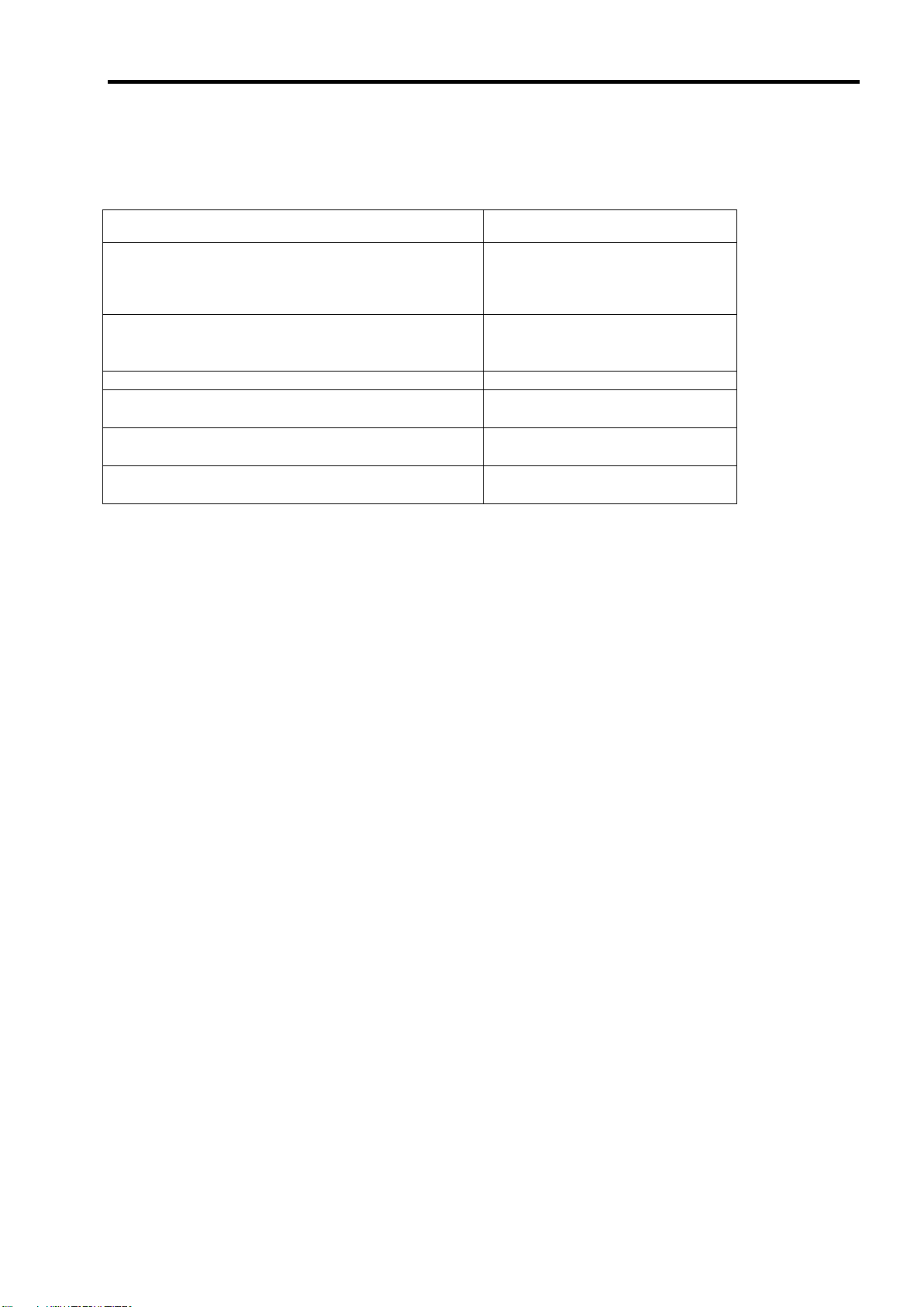
2.仕様
項 目
仕 様
備 考
SAS コネクタ数
内部 1 チャネル
1 チャネルに 2 ポート
キャッシュメモリ容量
256MB
キャッシュメモリのライト方式
ライトスルー
ライトバック未対応
キャッシュのバッテリィバックアップ
未対応
ライトスルー方式のみ
PCI バス
PCI Express 1.0A 準拠
ブレード用メザニンコネクタ
PCI Express (x8)
ブレード用メザニン拡張スロット
タイプ2スロット専用
最大 PCI バス転送レート
2,5Gigabits/lane
HDD デバイスインターフェース
SAS 対応
SAS 最大データ転送レート
300MB/sec
RAID レベル
0, 1
本体装置への最大搭載数
1 枚 最大 HDD 接続台数
2 台
1 チャネルに HDD2 台接続
外形寸法
113(幅)x135(長さ)x22(高)mm
ディスクアレイコントローラ本体
40(幅)x102(長さ)x39(高)mm
バックプレーン
質量
約 0.15kg
動作電圧
3.3V/12V
消費電力(MAX)
19.44W
3.3V/0.8A
12V/1.4A
動作環境
温度 10°C~35°C
湿度 20%~80%
結露しないこと
3
Page 24
4
本製品は、PCI ホットプラグ機能をサポートしておりません。
本製品を抜き差しする場合は、必ず本体装置をブレード格納ユニットから完
全に引き抜いてから行ってください。
3.本製品の特徴
本製品は、SAS 対応の I/F コネクタを 1 チャネル(1 チャネルに 2 ポート)有するハードウエア RAID のコ
ントローラです。データ転送速度は、1 ポートあたり最大 300MB/秒であり、高パフォーマンスを実現して
います。
本製品は、ディスクアレイコントローラ本体,バックプレーンボード,内部接続ケーブルにて構成されておりま
す。
本製品の特徴
最大 300MB/秒のデータ転送
256MB DDR-Ⅱ メモリを搭載
1 ボードあたり最大 2 台の SAS HDD を接続可能(1 チャネル当たり 2 台)
RAID レベル 0, 1 をサポート
ESMPRO を使った通報監視が可能
障害発生ドライブの自動検出
システムを停止せずに故障 HDD の交換(ホットスワップ)が可能
Page 25
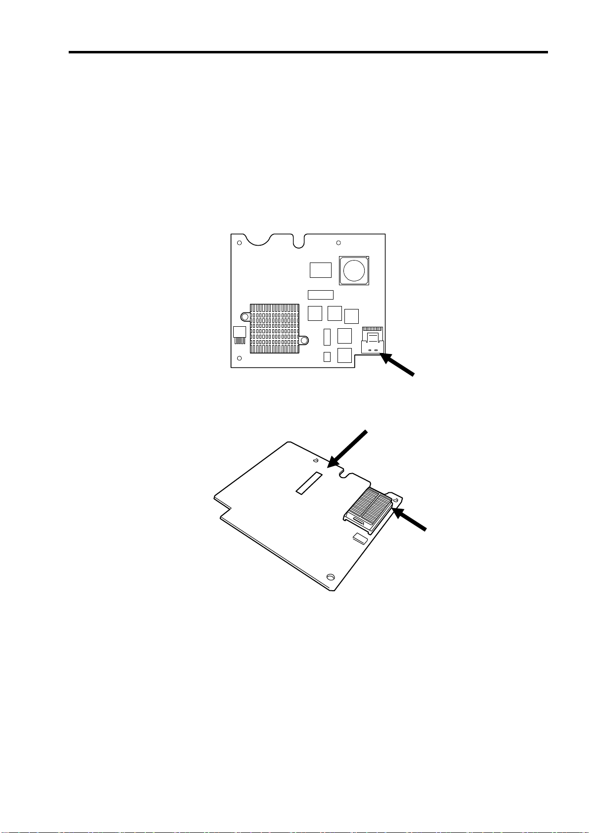
4.各部の名称と機能
①
チャネル 1(Port 0~1)コネクタ
バックプレーンとディスクアレイコントローラ本体を接続するためのコネクタです。
②
N コードラベル
本製品のNコードを表示しています。
③
ブレード用メザニンコネクタ
本製品を本体装置のメザニン拡張スロット(タイプ2)に接続するコネクタです。
①
②
③
本製品の構成品ならびに各部の名称を以下に説明いたします。
4-1.ディスクアレイコントローラ本体(1枚)
(ディスクアレイコントローラ本体表面)
5
(ディスクアレイコントローラ本体裏面)
Page 26
6
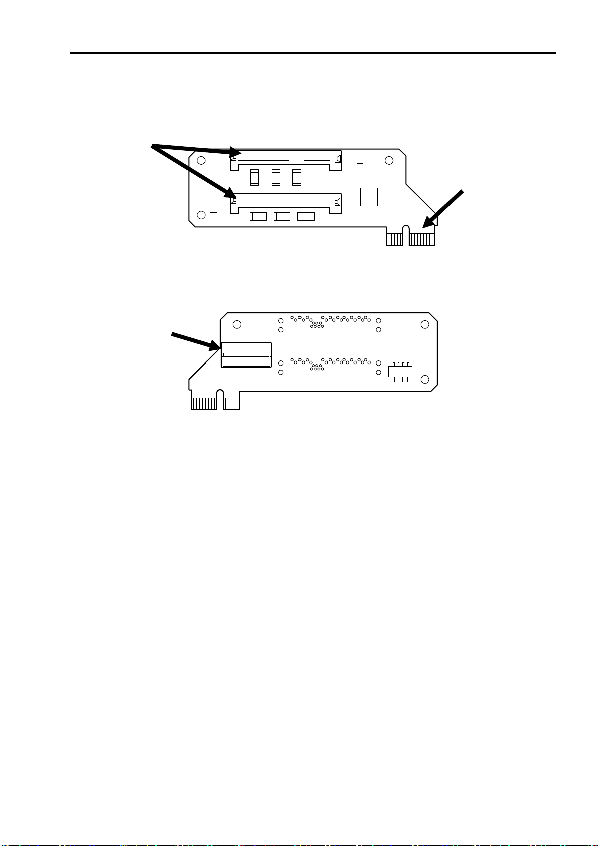
④
SAS コネクタ
バックプレーンとハードディスクを接続するためのコネクタです。
⑤
カードエッジコネクタ
本製品と本体装置を接続するためのカードエッジコネクタです。
⑥
内部接続コネクタ
バックプレーンとディスクアレイコントローラ本体を接続するためのコネクタです。
④ ⑤ ⑥
4-2.バックプレーンボード(1枚)
(バックプレーンボード表面)
(バックプレーンボード裏面)
Page 27
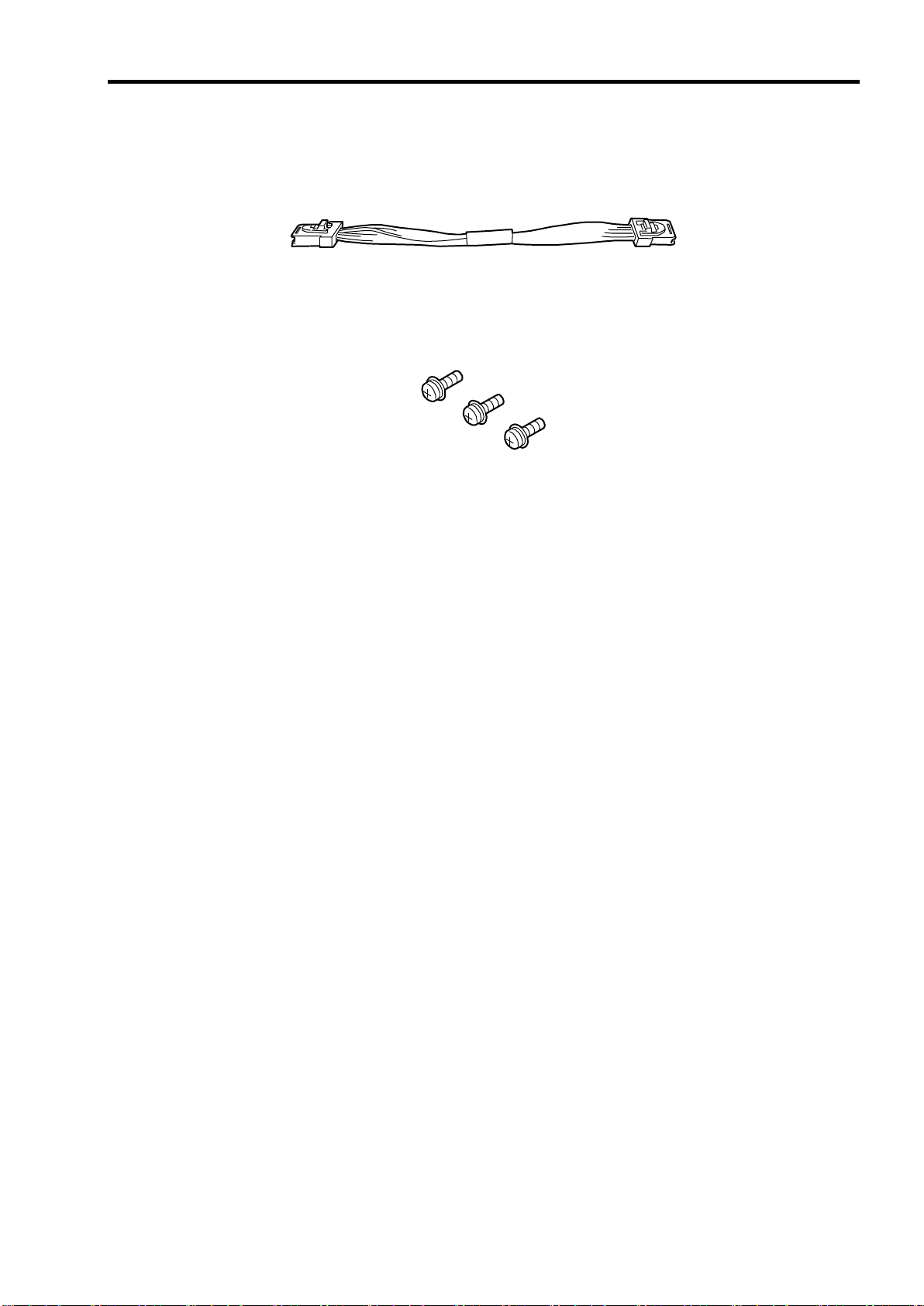
4-3.内部接続ケーブル(1本)
7
4-4.ディスクアレイコントローラ取り付けネジ(3個)
Page 28
8
RAID レベル
必要な HDD 数
最小
最大
RAID 0
1 2 RAID 1
2
2
各RAID レベルの詳細は、本章「2.RAID レベル」を参照してください。
第 2 章 RAID について
ここでは、本製品がサポートしている RAID 機能について説明します。
1. RAID の概要
1-1. RAID(Redundant Array of Inexpensive Disks)とは
直訳すると低価格ディスクの冗長配列となり、HDD を複数まとめて扱う技術のことを意味します。
つまり RAID とは複数の HDD を 1 つのアレイ(ディスクグループ)として構成し、これらを効率よく運用する
ことです。これにより単体の大容量 HDD より高いパフォーマンスを得ることができます。
本製品では、1つのディスクグループを複数の論理ドライブ(バーチャルディスク)に分けて設定することがで
きます。これらのバーチャルディスクは、ホストコンピュータからそれぞれ 1 つの HDD として認識されま
す。ホストコンピュータからのアクセスは、ディスクグループを構成している複数の HDD に対して並行して
行われます。
また、使用する RAID レベルによっては、ある HDD に障害が発生した場合でも残っているデータやパリティ
からリビルド機能によりデータを復旧させることができ、高い信頼性を提供することができます。
1-2. RAID レベルについて
RAID 機能を実現する記録方式には、複数の種類(レベル)が存在します。その中で本製品がサポートする RAID
レベルは、「RAID 0」「RAID 1」です。ディスクグループを作成する上で必要となる HDD の数量は RAID レ
ベルごとに異なりますので、下の表で確認してください。
Page 29
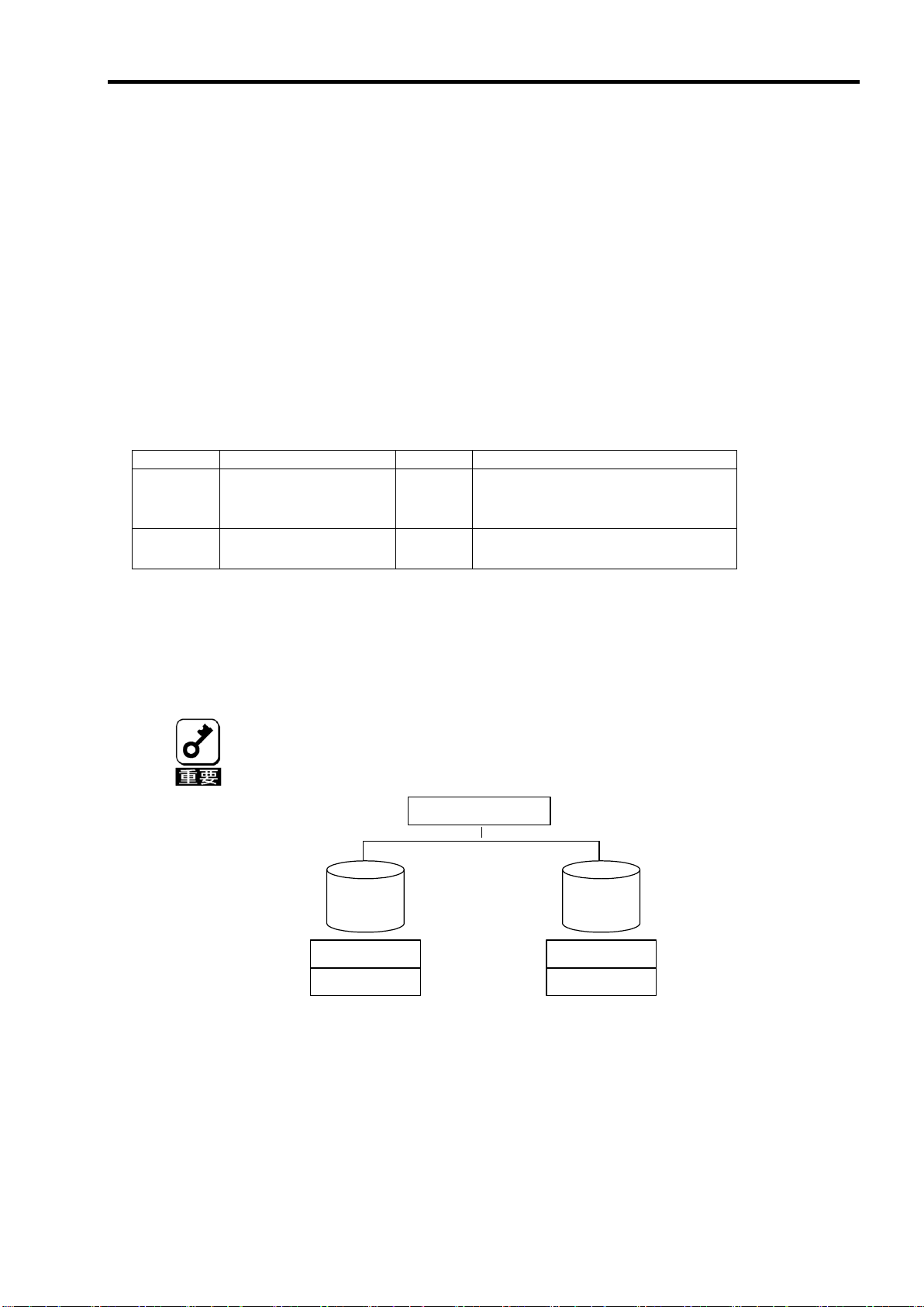
1-3.ディスクグループ(Disk Group)
ディスク 0
(36GB)
ディスク 1
(36GB)
ディスクアレイコントローラ
DG0 容量 72GB
ディスク 0
(36GB)
ディスク 1
(36GB)
ディスクアレイコントローラ
DG0 容量 72GB
VD1-2
16GB
VD1-1
16GB
VD0-1
20GB
VD0-2
20GB
VD0 (RAID1)
容量 20GB
VD1 (RAID1)
容量 16GB
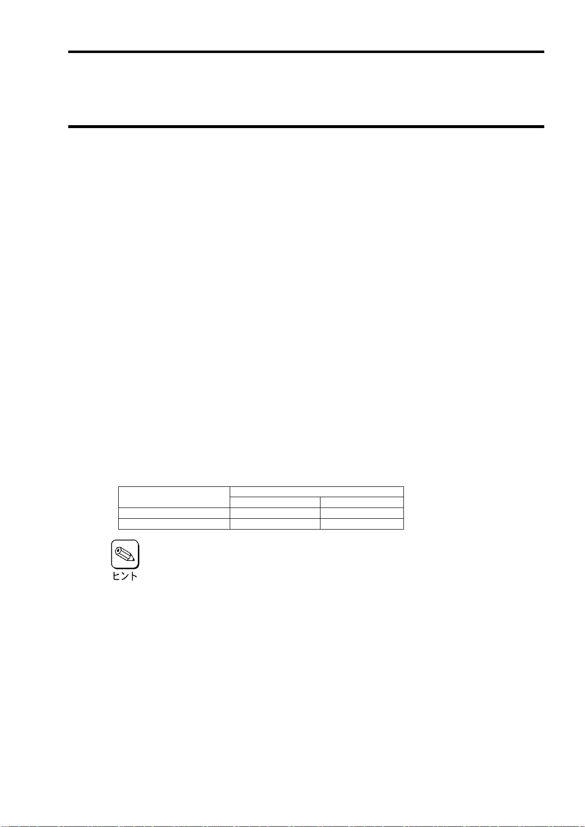
ディスクグループは複数の HDD をグループ化したものを表します。本製品の設定可能なディスクグループの
数は、HDD を 2 台実装した場合で最大 2 個になります。
次の図は本製品に HDD を 2 台接続し、2 台で1つのディスクグループ(DG)を作成した構成例です。
9
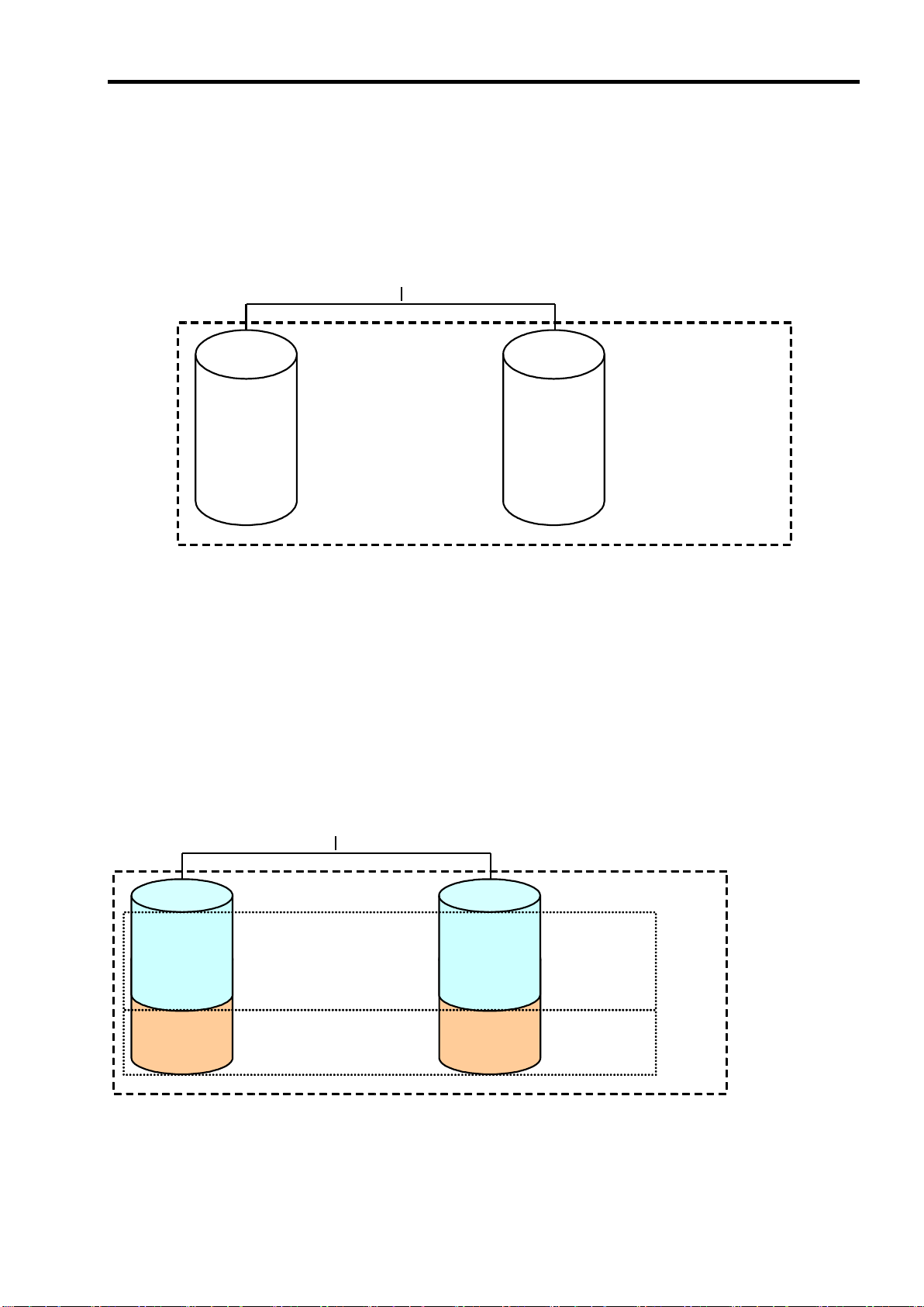
1-4.バーチャルディスク(Virtual Disk)
バーチャルディスクは作成したディスクグループ内に、論理ドライブとして設定したものを表し、OS から
は物理ドライブとして認識されます。本製品の設定可能なバーチャルディスクの数は、最大 40 個になります。
次の図は本製品に HDD を 2 台接続し、2台で1つのディスクグループ(DG)を作成し、その DG に RAID1 の
バーチャルディスク(VD)を2つ設定した構成例です。
Page 30
10
レベル
機 能
冗長性
特 徴
RAID0
ストライピング
なし
データ読み書きが最も高速
容量が最大
容量=HDD1 台の容量×HDD 台数
RAID1
ミラーリング
あり
HDD が 2 台必要
容量=HDD1 台の容量
RAID0はデータの冗長性がありません。HDDが故障するとデータの復旧が
できません。
アレイコントローラ
Disk 0
ストライプ 1
Disk 1
ストライプ 3
ストライプ 2
ストライプ 4
1-5.ホットスワップ
システムの稼働中に HDD の脱着(交換)を手動で行うことができる機能をホットスワップといいます。
2. RAID レベル
本製品がサポートしている RAID レベルについて詳細な説明をします。
2-1. RAID レベルの特徴
各 RAID レベルの特徴は下表の通りです。
2-2.「RAID0」について
データを各 HDD へ分散して記録します。この方式を「ストライピング」と呼びます。
図ではストライプ 1(Disk0)、ストライプ 2(Disk1)・・・というようにデータが記録されます。すべての HDD
に対して一括してアクセスできるため、最も優れたディスクアクセス性能を提供することができます。
Page 31

11
アレイコントローラ
Disk 0
Disk 1
ストライプ 1
ストライプ 2
ストライプ 1
ストライプ 2
2-3.「RAID1」について
1 つの HDD に対してもう 1 つの HDD へ同じデータを記録する方式です。この方式を「ミラーリング」と
呼びます。
1 台の HDD にデータを記録するとき同時に別の HDD に同じデータが記録されます。一方の HDD が故障し
たときに同じ内容が記録されているもう一方の HDD を代わりとして使用することができるため、システム
をダウンすることなく運用できます。
Page 32

12
リビルドを実行する場合は、以下の点に注意してください。
リビルドに使用するHDD は、故障したHDD と同一容量、同一回転数、
同一規格のものを使用してください。
リビルド中は負荷がかかるため、処理速度は低下します。
リビルド中は、本体装置のシャットダウンやリブートを実施しないでく
ださい。万が一、停電などの不慮な事故でシャットダウンしてしまった
場合、速やかに電源の再投入を行ってください。自動的にリビルドが再
開されます。
故障したHDD を抜いてから新しいHDD を実装するまでに、60秒以上の
間隔をあけてください。
ホットスワップリビルドが動作しない場合は、マニュアルリビルドを実
行してください。
RAID1の構成で、故障HDDを抜くと故障HDDが無くなったためにHDD単
体の故障状態ではなくなりますが、冗長性(ミラーリングの状態ではない)
がなくなりますので、すぐに新しいHDDでリビルドを実行してください。
第 3 章 本製品の機能について
本製品が持つ機能を説明します。
1.リビルド
リビルド(Rebuild)は、HDDに故障が発生した場合に、故障した HDD のデータを復旧させる機能です。HDD
故障時には、故障した HDD のアクセスランプがアンバー(橙)色に点灯します。リビルドは、『RAID1』の冗
長性のあるバーチャルディスクに対し、故障 HDD から新しい HDD への置き換え後に実行することができま
す。リビルド中は、交換された HDD のアクセスランプがアンバー(橙)色に点滅します。
1-1.マニュアルリビルド(手動リビルド)
本製品の管理ユーティリティ MegaRAID Storage ManagerTM(以降「MSM」と呼ぶ)かあるいは WebBIOS を
使用し、手動で実施するリビルドです。HDD を選択してリビルドを実行することができます。
詳しい操作方法については、本体装置添付の EXPRESSBUILDER に収められている「Express5800 シリー
ズ MegaRAID Storage ManagerTM ユーザーズガイド」をご覧ください。
1-2.オートリビルド(自動リビルド)
MSM などのユーティリティを使用せず、自動的にリビルドを実行させる機能です。
オートリビルドには、以下の方法があります。
ホットスワップリビルド
故障した HDD をホットスワップで新しい HDD に交換することにより、自動的にリビルドが実行さ
れる機能です。
Page 33
13
パトロールリードを実行する場合は、以下の点に注意してください。
パトロールリードは、工場出荷時は「Disable」に設定されています。
メディアパトロールを実施するためにはMSMのインストールが必要で
す。
パトロールリード実行中にシステムの再起動を行うと最初(HDDの先頭)
からパトロールリードをやり直します。
詳しい操作方法については、本体装置添付のEXPRESSBUILDERに収め
られている「Express5800 シリーズ MegaRAID Storage ManagerTM
ユーザーズガイド」をご覧ください。
整合性チェックを実行する場合は、以下の点に注意してください。
整合性チェック中は負荷がかかるため、処理速度は低下します。
整合性チェック実行中にシステムの再起動を行うと途中から再開しま
す。
詳しい操作方法については、本体装置添付のEXPRESSBUILDERに収め
られている「Express5800 シリーズ MegaRAID Storage ManagerTM
ユーザーズガイド」をご覧ください。
2.パトロールリード
パトロールリード(Patrol Read)は、HDD の全領域にリード&ベリファイ試験を実施する機能です。パトロー
ルリードは、MSM からバーチャルディスクに割り当てられているすべての HDD に対して実行することがで
きます。
パトロールリードにより、HDD の後発不良を検出・修復することができます。
冗長性のあるバーチャルディスクを構成する HDDやホットスペアディスクに割り当てられた HDD の場合は、
実行中に検出したエラーセクタを修復することができます。
3.整合性チェック
整合性チェック(Check Consistency)は、バーチャルドライブの整合性をチェックするための機能です。
『RAID1』の冗長性のあるバーチャルドライブに対して実行することができます。
整合性チェックは、WebBIOS や MSM から実施することができます。
整合性チェックは整合性をチェックするだけでなく、実行中に検出したエラーセクタを修復することができ
るため、予防保守として使用できます。
4.バックグラウンドイニシャライズ(BGI)
本製品では未サポートです。
Page 34

14
実行前
実行後
特 徴
RAID レベル
HDD 数
RAID レベル
HDD 数
RAID0
1 台
RAID1
2 台
容量は変更されない
リコンストラクションを実行する場合は、以下の点に注意してください。
リコンストラクション実行前に、必ずデータのバックアップを実施して
ください。
1つのディスクグループに複数のバーチャルディスクを作成している構
成には、リコンストラクションは実施できません。
リコンストラクション中は負荷がかかるため、処理速度は低下します。
縮退状態(Degraded)のバーチャルディスクには実行できません。リビル
ドを実行し、バーチャルディスクを復旧した後で実行してください。
リコンストラクション中は、本体装置のシャットダウンやリブートを実
施しないでください。万が一、停電等の不慮の事故でシャットダウンを
してしまった場合は、速やかに電源を再投入してください。再起動後、
自動的に再開されます。
5.リコンストラクション
リコンストラクション(Reconstruction)機能は、既存のバーチャルディスクの RAID レベルや構成を変更する
機能です。リコンストラクション機能には以下の3通りの機能がありますが、本製品では Migration with
addition のみをサポートしています。
5-1. Removed physical drive
本製品では未サポートです。
5-2. Migration only
本製品では未サポートです。
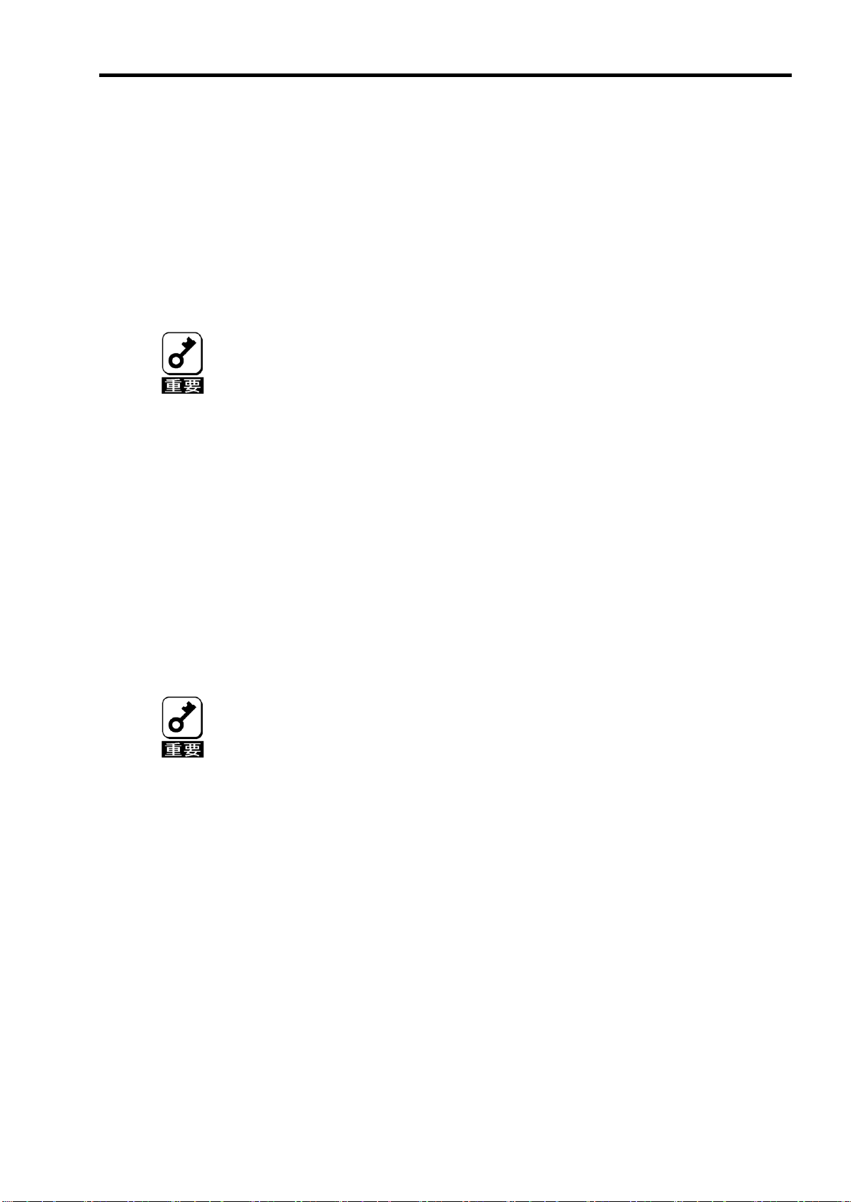
5-3. Migration with addition
既存のバーチャルディスクに HDD を追加する機能です。MSM 上では、「Add Drive」と表示されます。本機
能の実行パターンは以下の通りです。
Page 35

15
36GB
【実行前】
容量 = 36GB
バーチャルディスク(RAID0)
36GB
36GB
36GB
Migration with addition実行
バーチャルディスク(RAID1)
【実行後】
容量 = 36GB
例) RAID0 のバーチャルディスクの Migration with addition
以下は、36GB HDD×1 台で構成された RAID0 のバーチャルディスクに、36GB HDD を 1 台追加する場合
の例です。
Page 36

16
作業の前に本体装置のユーザーズガイドも必ずご覧になってください。作業
フローは本体装置や装置構成によって異なります。作業開始前に本体装置の
種類および装置構成を確認して正しいフローを実施してください。
セットアップ開始
4 章 1.セットアップの準備
4 章 2.本製品の取り付け
HDD の搭載
本体装置の電源投入
5 章 1. Web BIOS を使用する前に。
5 章. 2-1Web BIOS の起動
(コンフィグレーションユーティリティ)
5 章 3. バーチャルディスクの作成
5 章 4-1 整合性チェック(Check Consistency)
セットアップ終了
第4章 ハードウェアのセットアップ
次の手順に従って、本製品を本体装置に取り付けてください。
組み込み出荷時には、工場にてセットアップを行い出荷します。
Page 37

1.セットアップの準備
セットアップを行う前に、以下の注意事項をご覧ください。
本製品は、本体装置1台に対して1枚のみ実装可能です。複数枚の実装は
できません。
メザニン拡張 スロットには、本体装置により実装制限がある場合があり
ます。取り付ける前に本体装置のユーザーズガイドを確認してください。
同一装置内に、タイプ2のメザニンカードは1枚しか実装できません。
本製品に接続するHDD は、同一規格のHDD を使用してください。本製
品に接続可能なHDD については、お買い求めの販売店にご確認くださ
い。
本製品は、他のメザニンカード(LANコントローラ、SCSI コントローラ
等)の混在使用を制限している場合があります。本製品を他のメザニン
ボードと混在してご使用になる場合は、混在が可能かどうかお買い求め
の販売店にご確認ください。
本体装置サイドカバー等の取り付け/取り外し手順は、本体装置のユーザー
ズガイドをご覧ください。
1. すべてのアプリケーションを終了し、OS のシャットダウン処理を行います。
2. POWER スイッチを押して本体装置の電源をOFFにします。
17
3. 本体装置をブレード格納ユニットから完全に引き抜いてください。
4. 本体装置のユーザーズガイドの手順に従い、本体装置のサイドカバー等を外します。
Page 38

18
本製品は、PCI ホットプラグ機能には対応していません。本製品を抜き差
しする場合は、必ず本体装置をブレード格納ユニットから完全に引き抜いて
から行ってください。
メザニン拡張スロットには、本体装置により実装制限がある場合がありま
す。取り付ける前に本体装置のユーザーズガイドをご覧ください。
2.本製品の取り付け
ここでは、N8400-029/030 Express5800-120Bb-6 を例として、本体装置に本製品を取り付ける手順について
説明します。
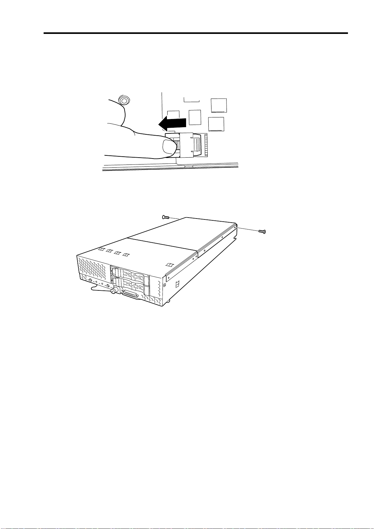
1. 両サイドのネジを取り外してください。
5. リアカバーを矢印方向へスライドさせます。
Page 39

6. リアカバーを上に持ち上げ取り外します。
本製品がメザニン拡張スロット(タイプ2)にうまく取り付けられない場合
は、一旦本製品を取り外して、再度取り付けなおしてください。過度の力を
加えると破損するおそれがありますので注意してください。
19
7. 本製品を取り付けるメザニン拡張スロット(タイプ 2)の位置を確認してください。
本製品をメザニン拡張スロット(タイプ 2)にしっかりと差し込み、添付のネジで固定します。
取り付け例.モデル 120Bb-6 の場合
Page 40

20
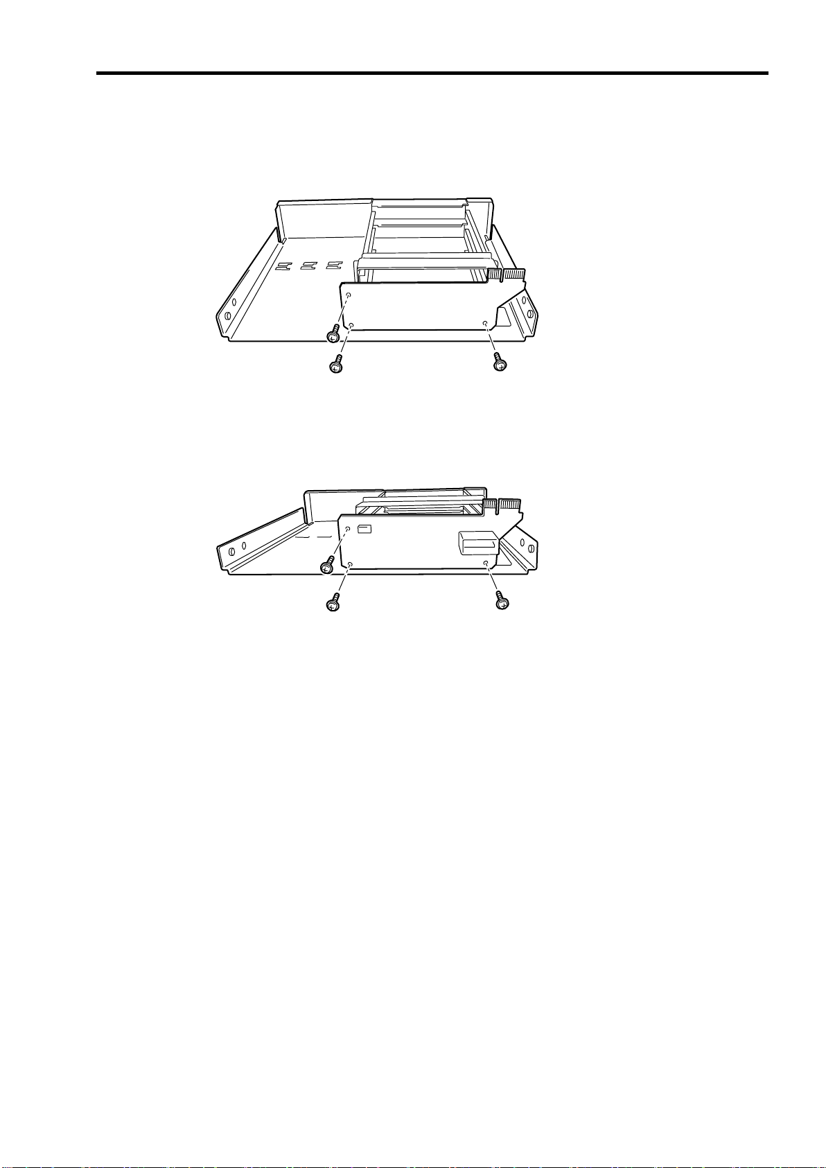
8. バックプレーンボードを取り付けます。
1) 本体装置にハードディスクドライブが実装されている場合は、取り外します。
2) フロントカバーの4箇所のネジを外します。
3) フロントカバーを矢印方向に垂直に上げ取り外します。
Page 41
21
4) 既存バックプレーンボードがある場合は、3箇所のネジを外し、既存バックプレーンボードを取
り外します。
5) 新規バックプレーンを、取り外した3箇所のネジを利用し取り付けます。
Page 42

22
6) フロントカバーを、コネクタの勘合に気を付けながら取り付けます。
7) フロントカバーの両サイドのネジを取り付けます。
Page 43
23
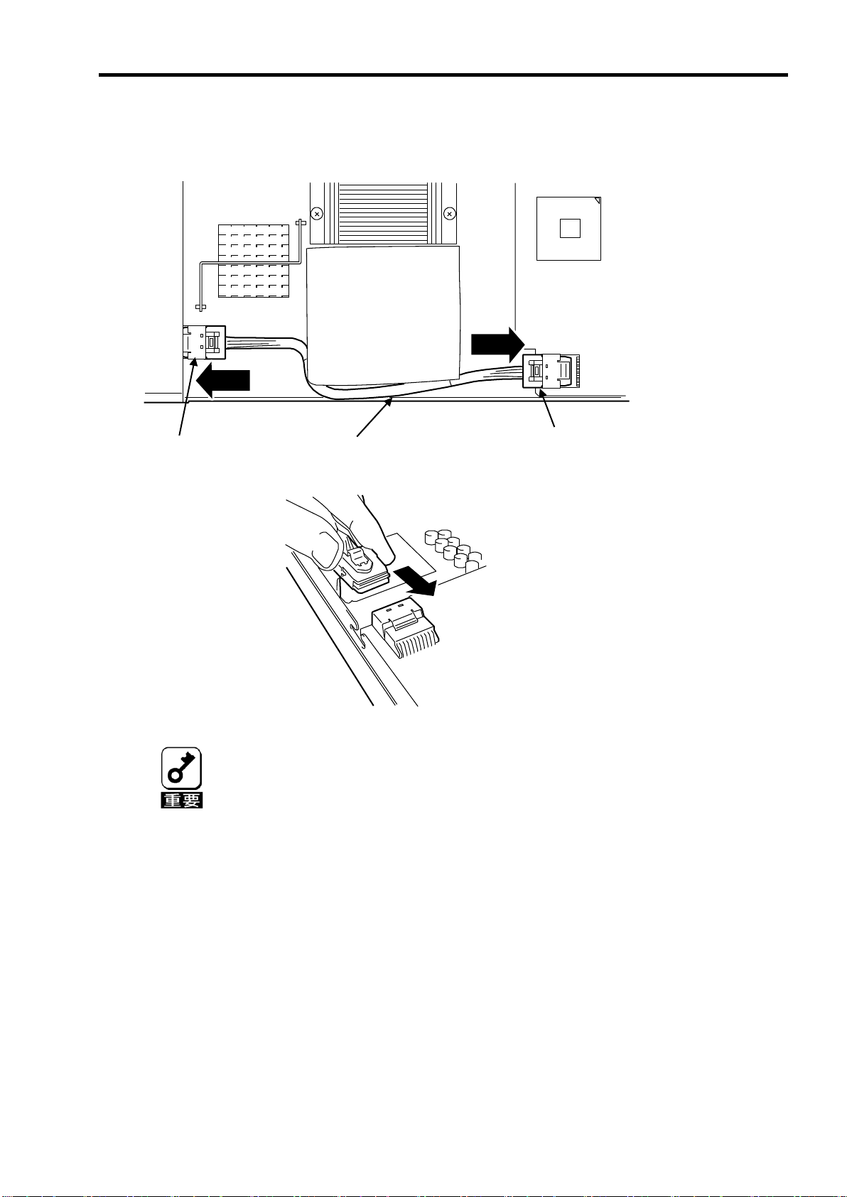
内部接続ケーブルをディスクアレイコントローラ本体側のコネク
タ、バックプレーン側のコネクタに、ロックピンが上になる向きに
ケーブルを合わせケーブルがロックされるまで差し込んでくださ
い。
ケーブルルートは、上図のルートになるように設置してください。
バックプレーン側コネ
内部接続ケーブル
デ ィ ス ク ア レ イ コ ン ト
9. 内部ケーブルを本製品の両コネクタに接続します。以下の図を参照して接続してください。ケーブル
が接続し難い場合は、一旦本製品をメザニン拡張スロット(タイプ2)から抜いて接続してください。
Page 44
24
ケーブルを外す場合は、ケーブルのロックピンを解除するため下図の場所を押しながら引き抜いて
ください。
10. リアカバーを取り付けます。
Page 45
第 5 章 バーチャルディスクの作成
RAID を構築する前に、実装される本体装置のシステム BIOS の
セットアップを変更する必要があります。
組み込み出荷の装置では下記設定が出荷時に行われておりますが、本体装置
のBIOSセットアップ画面にてLoad Setup Defaultsを実行した場合は、再設
定する必要があります。
Press<F2> to enter Setup or Press <F12> to network
ここでは本製品のコンフィグレーションユーティリティ「WebBIOS」について説明します。
1.WebBIOS を使用する前に
25
本体装置の電源投入後(POST 中)、上記のようなセットアップ画面へのメッセージが表示された時に、[F2]
キーを押すことによりセットアップ画面に移行できます。
1)実装カードのオプション ROM 有効化。
Advanced -> PCI Configuration -> Mezzanine Type 2 Option ROM のパラメータを、[Disabled] →:[Enabled]
に変更。
2)オンボード SCSI の無効化。
Advanced -> Embedded SCSI の各パラメータ
SCSI Controller : [Enabled] →[ Disabled]に変更。
Option ROM Scan: [Enabled] →[ Disabled]に変更。
RAID Enable : [Enabled] →[ Disabled]に変更。
Page 46

26
1-1.WebBIOS のサポート機能
「WebBIOS」を使用する前に、サポート機能および注意事項を確認ください。
HDD のモデル名/容量の情報表示
HDD の割り当て状態表示
バーチャルディスクの作成
RAID レベルの設定
Stripe Block サイズの設定
Read Policy/Write Policy/IO Policy の設定
バーチャルディスクの設定情報・ステータスの表示
バーチャルディスクの削除
コンフィグレーションのクリア
イニシャライズの実行
整合性チェックの実行
マニュアルリビルドの実行
リコンストラクションの実行
1-2.バーチャルドライブ作成時の注意事項
1) DG を構成する HDD は同一容量および同一回転のものを使用してください。
2) VD を構築した後、必ず Consistency Check を実施してください。
3) 本製品配下の VD に OS をインストールする際は、OS インストール用の VD のみを作成してください。
4) 一部の装置でマウスが使用できません。その場合、キーボードの TABキーで画面上に表示されているカー
ソルを移動し Enter キーで決定してください。Configuration Wizard でディスクまたはディスクグループを選
択する場合は Shift キーを押しながら上下のカーソルキーでディスクを選択してください。
5) WebBIOS は本体装置でサポートしている DianaScope のリモートコンソール機能では動作しません。
Page 47

2. WebBIOS の起動とメニュー
LSI MegaRAID SAS - MFI BIOS Version XXXX (Build MMM DD, YYYY)
Copyright (c) 2006 LSI Logic Corporation
HA - X (Bus X Dev X) MegaRAID SAS PCI Express(TM)ROMB
FW package: X.X.X - XXXX
0 Logical Drive(s) found on the host adapter.
0 Logical Drive(s) handled by BIOS.
Press <Ctrl> <H> for WebBIOS.
POST中は<Pause>キーなどの操作に関係ないキーを押さないでください。
Press<F2> to enter Setup or Press <F12> to network
2-1. WebBIOS の起動
1)本体装置の電源投入後、次に示す画面が表示された時に、[Esc]キーを押してください。
27
2) POST 中、下記 WebBIOS 起動 のメッセージが表示されたときに<Ctrl>+<H>キーを押すと POST 終了
後に WebBIOS が起動します。
【POST 画面イメージ(バーチャルディスク未設定時)】
Page 48

28
Adapter Selection
Adapter No.
Bus No
Device No
Type
Firmware Version
0. XX
XX
MegaRAID SAS PCI
Express(TM)ROMB
X.XX.XX - XXXX
Start
2-2. Main Menu
WebBIOS を起動すると最初に表示される[Adapter Selection]画面です。WebBIOS を用いて操作を実施する
コントローラを選択し、”Start”をクリックしてください。
Page 49

[Adapter Selection]を実行すると WebBIOS トップ画面が表示されます。
MegaRAID BIOS Configuration Utility Virtual Configuration
WebBIOS
Physical Drives
Enclosure XXX
PD 0: UNCONF GOOD: XXXX MB: XXXX XXXX
PD 1: UNCONF GOOD: XXXX MB: XXXX XXXX
Adapter Properties
Scan Devices
Virtual Disks
Physical Drives
Configuration Wizard
Adapter Selection
Physical View
Events
Exit
Virtual Drives
29
Page 50

30
MegaRAID BIOS Configuration Utility Adapter Information
MegaRAID SAS PCI Express(TM)ROMB
Firmware Version X.XX.XX-XXXX
WebBIOS Version X.XX-XXX
Sub Vendor ID
0x1033
Sub Device ID
0x8287
Host Interface
PCIE
Port Count
8
NVRAM Size
32 KB
Memory Size
256 MB
Firmware Time
XXX XX XXXX;XX:XX:XX
Serial Number
XXXXXXXX
Min Stripe Size
8 KB
Max Stripe Size
128K
Virtual Disk Count
XX
Physical Disk Count
XX
FW Package Version
X.X.X-XXXX
Next
Home
Back
2-3. Adapter Properties
WebBIOS トップ画面にて[Adapter Properties]をクリックすると、本製品の設定情報を表示することができま
す。
Page 51

設定情報画面にて[Next]をクリックすると、本製品の詳細設定を表示することができます。
MegaRAID BIOS Configuration Utility Adapter Properties
Properties
Battery Back Up
None
Coercion Mode
None
Set Factory Defaults
No
PDF Interval
300
Cluster Mode
Disabled
Alarm Control
Disabled
Rebuild Rate
30
Patrol Read Rate
30
BGI Rate
30
Cache Flush Interval
4
CC Rate
30
Spinup Drive Count
2
Reconstruction Rate
30
Spinup Delay
6
Adapter BIOS
Enabled
Stop On Error
Disabled
Submit
Reset
Home
Back
31
Page 52

32
項目
設定値
説明
変更可否
備考
Battery Backup
Present
None
バッテリのプロパティ画面を表
示します。
本製品はバッテリバックアップ
をサポートしません。
Set Factory Defaults
No
Yes
本製品の設定を工場出荷時の状
態に戻します。
可
Cluster Mode
Disabled
不可
Rebuild Rate
30
奨励設定値: 30
可
Patrol Read Rate
30
奨励設定値: 30
可
BGI Rate
30
奨励設定値: 30
可
CC Rate
30
奨励設定値: 30
可
Reconstruction Rate
30
奨励設定値: 30
可
Adapter BIOS
Enabled
Disabled
不可
Coercion Mode
None
128MB-way
1GB-way
不可
PDF Interval
300
不可
Alarm Control
Disabled
Enabled
Silence
Disabled:アラームなし
Enabled:アラームあり
Silence:アラームを停止します
可
Cache Flush Interval
4
不可
Spinup Drive Count
2
不可
Spinup Delay
6
不可
Stop On Error
Disabled
Enabled
不可
初期設定および、設定値説明
設定値変更方法
[Adapter Properties]画面にて設定変更可能なパラメータを変更した後、画面中央にある[Submit]ボタンをク
リックして設定値を確定してください。
Page 53

33
新たに接続したHDDに他のコンフィグレーション情報が保存されている場
合、下記の[Foreign Configuration]画面が表示されます。そのまま新規HDD
として使用する場合は、”ClearForeignCfg”をクリックしてください。
新たに接続したHDD内のコンフィグレーション情報がクリアされます。
HDD内のコンフィグレーションを使用する場合には、”GuidPreview”をク
リックするとコンフィグレーションの内容を確認することが出来ます。
内容を読み込む場合には、確認画面で”Import”をクリックすることにより読
み込まれます。
MegaRAID BIOS Configuration Utility Foreign Configuration
GuidPreview
ClearForeignCfg
Cancel
1 Foreign Config(s) Found. Want to Import?
Select GUID
0NEC
2-4. Scan Devices
WebBIOSトップ画面にて[Scan Devices]をクリックすると、本製品に接続されている HDDを再認識します。
この機能は WebBIOS 起動後に新たな HDD を接続した際に有効です。
Page 54

34
MegaRAID BIOS Configuration Utility Virtual Disks
VD X: RAID X: XXXXXX MB: Optimal
Fast Initialize
Slow Initialize
Check Consistency
Properties
Set Boot Drive (Current = 0)
Go Reset
Home
Back
VDが存在しない場合は、画面右上の欄にVDが表示されません。 本操作画
面はVDが存在するときに使用してください。
2-5. Virtual Disks
WebBIOS トップ画面にて[Virtual Disks]をクリックすると、すでに構成されている VD に対する操作画面が表
示されます。
Page 55

35
MegaRAID BIOS Configuration Utility Physical Disks
Enclosure XXX
PD 0: UNCONF GOOD: XXXXXX MB: XXXX XXXXX
PD 1: UNCONF GOOD: XXXXXX MB: XXXX XXXXX
Rebuild
Properties
Go Reset
Home
Back
PD の番号は、HDD 毎に順次割り振られますので必ずしも HDD の
スロット番号とは一致しません。表示されている PD の HDD ス
ロット番号を確認するには、次ページに記載している Physical
Drive の Property にて知ることが出来ます。
PD が存在しない場合は、画面右上の欄に PD が表示されません。
本操作画面は PD が存在するときに使用してください。
2-6. Physical Drives
WebBIOS トップ画面にて[Physical Disks]をクリックすると、本製品に接続されている Physical Drive(HDD)
に対する操作画面が表示されます。
Page 56

36
MegaRAID BIOS Configuration Utility Physical Disks
Enclosure XXX
PD 0: UNCONF GOOD: XXXXXX MB: XXXX XXXXX
PD 1: UNCONF GOOD: XXXXXX MB: XXXX XXXXX
Rebuild
Properties
Go Reset
Home
Back
① ② ③
Physical Drives Properties
Physical Drive の Property により、PD(HDD)の実装スロットなど個別情報を確認することが出来ます。
Physical Drive が実装されている実際の HDD スロット番号を知ることが出来ます。
Physical Drive 番号 0 の Property を確認する例を説明します。
①確認する PD0 をクリックします。
②Properties のチェック欄をクリックします。
③Go のアイコンボタンをクリックしますと、PD0 の情報が表示されます。
Page 57

37
MegaRAID BIOS Configuration Utility Physical Drive 0
Revision
XXXX
Enclosure ID
XXX
Slot Number
0
Device Type
Disk
Connected Port
0
Media Errors
XX
Pred Fail Count
XX
SAS Address
XXXXXX
Physical Drive State
UNCONF GOOD
Coerced Size
XXXXX MB
DG 0
Make Global HSP
Make Dedicated HSP
Make Unconf Bad
Prepare for Removal
Locate
Go
Home
Back
④
④Slot Number は、本体装置の HDD スロット番号を示します。この例では、スロット 0 に実装されているこ
とを示します。
⑤
⑤終了するには、Home か、Back のアイコンボタンをクリックしてください。
Page 58

38
本製品では、Events機能をサポートしていません。
2-7. Configuration Wizard
本製品に接続した HDD を用いて RAID を構築する機能です。本機能については次項”バーチャルディスクの
構築”にて説明します。
2-8. Adapter Selection
本体装置に本製品を複数枚実装した際に、各アダプターの設定を行うために、WebBIOS にてコントロールす
るアダプターを変更する必要があります。WebBIOS トップ画面より[Adapter Selection]をクリックすると、
WebBIOS 起動時に表示される[Adapter Selection]画面が再度表示されます。
2-9. Physical View / Logical View
本製品を用いて VD を構築している場合、WebBIOS トップ画面にディスクグループ(DG)が表示されます。
[Physical View]をクリックすると、DG を構築している HDD の情報が表示されます。[Logical View]をクリッ
クすると、DG 内で構築されている VD が表示されます。
2-10. Events
イベント情報を確認する画面です。
Page 59

39
Exit Configuration
Exit Application
No
Yes
Reset Page
Please Reboot your System
2-11. Exit
WebBIOS トップ画面より[Exit]をクリックすると、WebBIOS を終了するための確認画面が表示されます。
WebBIOS を終了する際は、下記画面にて[Yes]をクリックしてください。
WebBIOS が終了すると、下記の画面が表示されます。本体装置を再起動してください。
Page 60
40
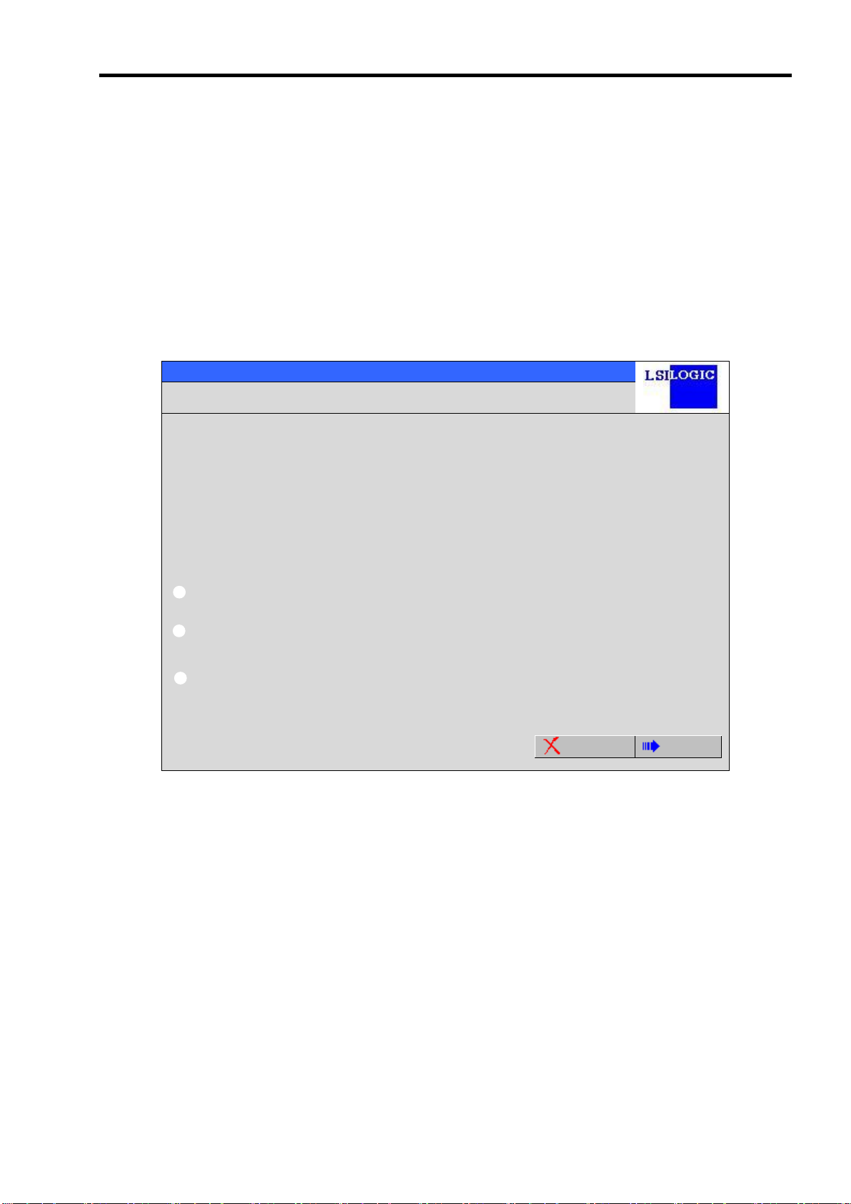
MegaRAID BIOS Configuration Utility Configuration Wizard
Configuration Wizard guides you through the steps for configuration the MegaRAID
System easily and efficiently. The steps are as follows:
1. Disk Group definitions
Group physical drives into Disk Groups.
2. Virtual Disk definitions
Define virtual disks using those arrays.
3. Configuration Preview
Preview configuration before it is saved.
Please choose appropriate configuration type:
Clear Configuration
Allows you to clear existing configuration only.
New Configuration
Clears the existing configuration. If you have any existing data
in the earlier defined drives, the data will be lost.
Add Configuration
Retains the old configuration and then adds new drives to the
configuration. This is the safest operation
as it does not result in any data loss.
Cancel
Next
Clear Configuration
コンフィグレーションをクリアします。
New Configuration
コンフィグレーションをクリアし、新しい VD を作成します。既存
VD が存在する場合はご注意ください。
Add Configuration
既存 VD が存在する状態で、新たに VD を追加します。
3. バーチャルディスクの作成
ここでは WebBIOS を用いて、VD(バーチャルディスク)を構築する手順を説明します。
3-1.Configuration Wizard
WebBIOS を起動し、トップ画面より[Configuration Wizard]をクリックすると、下記の画面が表示されます。
該当する操作を選択し、画面右下の[Next]をクリックしてください。
Page 61

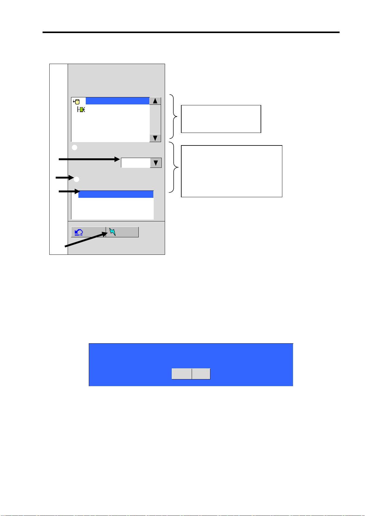
[New Configuration]または[Add Configuration]を選択した場合、下記の画面が表示されます。
MegaRAID BIOS Configuration Utility Configuration Wizard
Wizard can be define the most efficient configuration for your system (Auto Configuration),
Or if you are an experienced user, Wizard can take you through the steps
(Custom Configuration)
Custom Configuration:
Allows you to define all aspects of the
configuration, disk groups, virtual disks, and
their parameters.
Auto Configuration: with Redundancy
(Recommended)
Automatically creates redundant disk groups
and virtual disks, where possible, and sets
their parameters.
Auto Configuration: without Redundancy
Automatically creates non-redundant disk
groups and virtual disks, and sets their
parameters.
Cancel
Back
Next
Custom Configuration:
手動コンフィグレーションを実施します。
(RAID レベルやサイズ等を全て手動操作で決定します。)
Auto Configuration:
with Redundancy
自動コンフィグレーションを実施します。
(冗長性のある RAID レベルにて VD が構築されます。)
Auto Configuration:
without Redundancy
自動コンフィグレーションを実施します。
(冗長性の無い RAID レベルにて VD が構築されます。)
本製品では”Custom Configuration”機能のみをサポートしています。
本体装置に添付のEXPRESSBUILDERを使ってもコンフィグレーションす
ることが出来ます。
41
Page 62

42
MegaRAID BIOS Configuration Utility ConfigWizard - DG Definition
Disk Group Definition:
To add drives to a Disk Group, hold Control key while selecting
Unconf Good drives and click on Accept DG, Drive addition can be
undone by selecting the Reclaim button.
Physical Drives
Disk Groups
Enclosure XXX
PD 0: UNCONF GOOD: XXXXX MB:
PD 1: UNCONF GOOD: XXXXX MB:
Reset
Accept DG
Reclaim
Cancel
Back
Next
Custom Configuration
複数台の PD(Physical Drive)をひとまとめの DG(Disk Groups)として定義します。
Page 63

43
Physical Drives
Disk Groups
Enclosure XXX
PD 0: UNCONF GOOD: XXXXX MB:
PD 1: UNCONF GOOD: XXXXX MB:
Reset
Accept DG
Reclaim
Physical Drives
Disk Groups
Enclosure XXX
PD 0: UNCONF GOOD: XXXXX MB:
PD 1: UNCONF GOOD: XXXXX MB:
Reset
Accept DG
Reclaim
Physical Drives
Disk Groups
Enclosure XXX
PD 0: A0: ONLINE: XXXXX MB:
PD 1: A0: ONLINE: XXXXX MB:
DG X: R0 = XXXXX MB, R5 = XXXXX MB
PD 0: ONLINE: XXXXX MB:
PD 1: ONLINE: XXXXX MB:
Reset
Accept DG
Reclaim
① DG を構成する Physical Drive(HDD)を<Ctrl>キーを押しながらクリックすることで、複数台選択します。
② 選択完了後、画面右下の[Accept DG]をクリックします。
③ 画面右側 Disk Groups の欄に、新しい DG が構築されます。DG の構築終了後、画面右下の[Next]をクリッ
クします。
Page 64

44
MegaRAID BIOS Configuration Utility ConfigWizard – VD Definition
Virtual Disk 0
Configuration
RAID Level
RAID 1
DG 0 :R0 = XXXXX MB, R1 = XXXXX MB
Disk Group n: RAID Level = Size Available
Strip Size
64 KB
Access Policy
RW
Read Policy
Normal
Write Policy
WThru
IO Policy
Direct
Disk Cache
Policy
Unchanged
Disable BGI
No
Select Size
MB
Accept
Reset
Cancel
Back
Next
前画面の操作で作成した DG 内に VD を構築します。DG 確定後、VD 定義画面が表示されます。画面右側の
Configuration 欄内には構築した DG と、DG 内に構築可能な VD の RAID レベルおよび最大サイズが表示さ
れています。
「Configuration Wizard」の設定項目一覧です。
Page 65

VD Definition 設定項目
設定項目
パラメータ
備考
RAID Level
RAID 0 / RAID 1
Strip Size
8 KB / 16 KB / 32 KB / 64 KB / 128 KB
奨励設定値: 64KB
Access Policy
RW / Read Only / Blocked
奨励設定値: RW
Read Policy
Normal / Ahead / Adaptive
Normal: 先読みを行わない。出荷時設定。
ReadAhead: 先読みを行う。
Adaptive:
2 回連続して継続したセクタに対してア
クセスを行った場合先読みを行う。
Write Policy
WBack / WThru / BadBBU
WBack: 使用不可
WThru: ライトスルー
BadBBU: 使用不可
IO Policy
Direct / Cached
Direct: 推奨設定値。
ハー ド ディスク か らのリード デ ータを
直接 デ ータ転送 す ると共に本 製 品内の
キャッシュに書き込みます。同一ブロッ
クの デ ータ読み 出 しが行われ た 場合に
は、書き込まれたキャッシュからデータ
転送を行います。
Cached:
ハードディ スクからの リードデータ を
本製品内のキャッシュに書き込み、
キャ ッ シュ内か ら データ転送 を 行いま
す。
Disk Cache
Policy
Unchanged / Enable / Disable
奨励設定値: Uncharged
Disable BGI
No / Yes
VD 作成後に Back Ground Initialize を実
施するか否かを設定します。
奨励設定値: No
本製品では、BGI (Back Ground Initialize)は未サポートです。
45
Page 66

46
MegaRAID BIOS Configuration Utility ConfigWizard – VD Definition
Virtual Disk 0
Configuration
RAID Level
RAID 1
DG 0 :R0 = XXXXX MB, R1 = XXXXX MB
Disk Group n: RAID Level = Size Available
Strip Size
64 KB
Access Policy
RW
Read Policy
Normal
Write Policy
WThru
IO Policy
Direct
Disk Cache
Policy
Unchanged
Disable BGI
No
Select Size
YYYYY
MB
Accept
Reset
Cancel
Back
Next
②
例として、RAID 1 サイズ YYYYY MB の VD を構築します。
① 画面左側 Virtual Disk 欄へ必要なパラメータを入力します。
② “Select Size”欄へ RAID 1 にて構築できる最大サイズ YYYYY を入力します。
③ 画面中央下、[Accept]をクリックします。
Page 67

④ DG 0 内に VD 0 が構築され、以下の画面が表示されます。
MegaRAID BIOS Configuration Utility ConfigWizard - DG Definition
Disk Group Definition:
To add drives to a Disk Group, hold Control key while selecting
Unconf Good drives and click on Accept DG, Drive addition can be
undone by selecting the Reclaim button.
Physical Drives
Disk Groups
Enclosure XXX
PD 0: DG0: ONLINE: XXXXX MB:
PD 1: DG0: ONLINE: XXXXX MB:
:
DG 0
VD 0: RAID1: YYYYY MB: Optimal
Cancel
Back
Accept
47
⑤ 構築した VD に誤りがなければ、画面右下の[Accept]をクリックします。
⑥ “Save this Configuration?” というメッセージが表示されますので、コンフィグレーションを保存する場
合は”Yes”をクリックします。
⑦ “All data on the new Virtual Disks will be lost. Want to Initialize?” と新規 VDに対しイニシャライズ実行の
警告メッセージが表示されます。HDD を初期化しまいますので対象 HDD を確認し”Yes”をクリックして
ください。
⑧ “Virtual Disks”操作画面が表示されます。他の操作を行う必要が無い場合は、画面左下の[Home]をクリッ
クしてください。
Page 68

48
MegaRAID BIOS Configuration Utility Virtual Configuration
WebBIOS
Physical Drives
Enclosure XXX
PD 0: DG 0: ONLINE: XXXX MB: XXXX XXXX
PD 1: DG 0: ONLINE: XXXX MB: XXXX XXXX
Adapter Properties
Scan Devices
Virtual Disks
Physical Drives
Configuration Wizard
Adapter Selection
Physical View
Events
Exit
Virtual Drives
DG 0
VD 0: RAID 1: YYYYY MB: Optimal
⑨ WebBIOS トップ画面が表示され、画面右下に構築した VD が表示されます。
Page 69

4. 各種機能操作方法
MegaRAID BIOS Configuration Utility Virtual Configuration
WebBIOS
Physical Drives
Enclosure XXX
PD 0: DG 0: ONLINE: XXXX MB: XXXX XXXX
PD 1: DG 0: ONLINE: XXXX MB: XXXX XXXX
Adapter Properties
Scan Devices
Virtual Disks
Physical Drives
Configuration Wizard
Adapter Selection
Physical View
Events
Exit
Virtual Drives
DG 0
VD 0: RAID 1: YYYYY MB: Optimal
②
4-1. 整合性チェック機能(Check Consistency)
① WebBIOS を起動します。
② WebBIOS トップ画面の左側欄より、[Virtual Disks]をクリックします。
49
Page 70

50
MegaRAID BIOS Configuration Utility Virtual Disks
VD X: RAID X: XXXXXX MB: Optimal
Fast Initialize
Slow Initialize
Check Consistency
Properties
Set Boot Drive (Current = 0)
Go Reset
Home
Back
③ ④ ⑤
③ Virtual Disks 画面右上より、Check Consistency を実行する VD を選択します。
④ Virtual Disks 画面右下より、Check Consistency チェック欄をクリックします。
⑤ チェックマークを確認した後、[Go]をクリックします。
Page 71

⑥ Virtual Disks 画面左に、Check Consistency の進捗が表示されます。
MegaRAID BIOS Configuration Utility Virtual Disks
Abort
Progress
Operation
VD0
0%
Check
Consistency
Progress
VD X: RAID X: XXXXXX MB: Optimal
Fast Initialize
Slow Initialize
Check Consistency
Properties
Set Boot Drive (Current = 0)
Go Reset
Home
Back
Consistency Check, Rebuildおよびリコンストラクション等のバックグラン
ドタスクを実行中はWebBIOSトップ画面に戻るようにしてください。進捗
画面を表示したままですと、本体装置によってはバックグランド処理が遅く
なる場合があります。
⑦
⑥
51
⑦ Virtual Disks 画面左下の[Home]をクリックして、トップ画面に戻ってください。
Page 72

52
Physical Drives
Enclosure XXX
PD 0: DG 0: ONLINE: XXXX MB: XXXX XXXX
PD 2: UNCONF GOOD: XXXX MB: XXXX XXXX
PD Missing from DG0: slot1: XXXX MB
Virtual Drives
DG 0
VD 0: RAID 1: YYYYY MB: Degraded
③
②
4-2. Manual Rebuild 機能
HDD 2 台を用いて、RAID1 の VD を構築している環境において、HDD が 1 台(スロット 1)故障したケースを
例に説明します。故障した HDD を本体装置の電源をオフにしてから新しい HDD と交換した場合、ディスク
アレイコントローラが活栓交換を認識できないため、Auto Rebuild 機能は動作しません。その場合には、下
記にて説明する Manual Rebuild 機能を用いて VD を復旧します。
① WebBIOS を起動します。トップ画面右横において、交換した HDD のステータスが”UNCONF GOOD”
であることを確認します。
② 以前にスロット1に実装されていた HDD が無くなっていることを示します。
③ “Physical Drives”欄より、新しく接続した HDD(PD 2)をクリックします。
Physical Drive のプロパティ画面が表示されます。
Page 73

④ 画面右下の”Make Global HSP”を選択し、画面中央下の[Go]をクリックしてください。
MegaRAID BIOS Configuration Utility Physical Drive 2
Revision
XXXX
Enclosure ID
XXX
Slot Number
1
Device Type
Disk
Connected Port
1
Media Errors
XX
Pred Fail Count
XX
SAS Address
XXXXXX
Physical Drive State
UNCONF GOOD
Coerced Size
XXXXX MB
DG 0
Make Global HSP
Make Dedicated HSP
Make Unconf Bad
Prepare for Removal
Locate
Go
Home
Back
Global HSP:
全ての DG に対し使用可能な Hot Spare Disk のことです。
Dedicated HSP:
特定の DG に対し使用可能な Hot Spare Disk のことです。設定
する際には、使用する先の DG を指定する必要があります。
④
⑤ Rebuild(再構築)が始まります。
53
⑤ “Rebuild Progress”が表示されますので、画面左下の[Home]をクリックして WebBIOS トップ画面に戻っ
てください。
Page 74

54
Physical Drives
Enclosure XXX
PD 0: DG 0: ONLINE: XXXX MB: XXXX XXXX
PD 1: UNCONF GOOD: XXXX MB: XXXX XXXX
Virtual Drives
DG 0
VD 0: RAID 1: YYYYY MB: Optimal
4-4. リコンストラクション機能
HDD 1 台を用いて、RAID0 の VD を構築している環境において新たに HDD を追加し、HDD 2 台 RAID1 の
VD へ変更するケースを例に説明します。
① WebBIOS を起動します。トップ画面右横において、追加した HDD のステータスが”UNCONF GOOD”
であることを確認します。
② “Virtual Drives”欄より、あらかじめ構築されている VD 0 をクリックします。
Page 75

③ VD 0 の設定画面が表示されます。
MegaRAID BIOS Configuration Utility Virtual Disk 0
Properties
physical drive
RAID Level: 0
State: Optimal
Size: XXXXXX MB
Strip Size: XX KB
DG 0
PD 0: XXXXXX MB
Policies
Access
RW
Read
Normal
Disk Cache
Unchanged
Write
WThru
Migration only
Disable BGI
No
I / O
Direct
RAID 0
Change
Migration with addition
PD 0: XXXXX MB
Reset
Go
Operations
Del
Locate
Fast
Slow
Go
Home
Back
55
Page 76
56
physical drive
DG 0
PD 0: XXXXXX MB
Migration only
RAID 1
Migration with addition
PD 1: XXXXX MB
Reset
Go
Migration is not a reversible operation. Do you want to proceed?
No
Yes
VD が定義されている DG
を構築する HDD 情報
Migration Only:
RAID レベルの変更のみ
Migration with addition:
HDDの追加および RAIDレベルの
変更
⑤
⑥ ⑦ ⑧
④ 画面右側に、リコンストラクション機能に必要な項目が表示されています。
⑤ “Migration with addition”を選択します。
⑥ リコンストラクション後の RAID レベルを決定します。
⑦ 追加する HDD を選択します。
⑧ ⑤~⑦の操作が完了しましたら、画面右下[Go]をクリックしてください。
⑨ リコンストラクションを開始すると途中で止めたり元に戻すことは出来ません。
下記確認メッセージが表示されますので構成を再確認し問題が無ければ”Yes”をクリックして開始してく
ださい。
Page 77

57
リコンストラクション実行後に、バーチャルディスクの容量が正常に表
示されない場合があります。その場合はトップ画面からScan Devicesを
実施してください。
Consistency Check, Rebuildおよびリコンストラクション等のバックグ
ランドタスクを実行中はWebBIOSトップ画面に戻るようにしてくださ
い。進捗画面を表示したままですと、本体装置によってはバックグラン
ド処理が遅くなる場合があります。
⑩ 画面左下に進捗が表示されます。画面左下の[Home]をクリックして、WebBIOS トップ画面に戻ってく
ださい。
Page 78

58
整合性チェックを実施するためには、MSM のインストールが必要になりま
す。
第 6 章 運用・保守
1.保守サービス
保守サービスは NEC の保守サービス会社、および NEC が指定した保守サービス会社によってのみ実施さ
れますので、純正部品の使用はもちろんのこと、技術力においてもご安心の上、ご都合にあわせてご利用い
ただけます。
なお、お客さまが保守サービスをお受けになる際のご相談は、弊社営業担当または代理店で承っております
のでご利用ください。
2.予防保守
2-1.データのバックアップ
万が一の場合に備え、定期的に HDD 内のデータをバックアップすることをお勧めします。
データのバックアップについては、本体装置のユーザーズガイドをご覧ください。
また、本製品のコンフィグレーション情報は、本体装置に添付の EXPRESSBUILDER に収められているツー
ルにより保存や復元を行うことが出来ますので、コンフィグレーション情報を保存しておくことをお勧めし
ます。
使用方法につきましては、本体装置のユーザーズガイドをご覧ください。
2-2.整合性チェックによる予防保守
HDD の後発不良に対する予防保守として、整合性チェックを定期的に実施することをお勧めします。この機
能により、HDD の後発不良を早期に発見し修復することができます。
整合性チェックの詳しい機能については、『第 3 章本製品の機能について』をご覧ください。
実行の間隔は週に 1 度実施されることを推奨していますが、お客さまの運用状況に合わせ、尐なくとも月に
1 度は実施されることをお勧めしています。
Page 79

59
本製品はコンフィグレーション情報をディスクアレイコントローラ内に保
存しません。コンフィグレーション情報は、すべてHDD 内に記録/保存され
ます。
3.保守機能について
本製品で以下の保守機能をサポートしています。
Configuration on Disk(COD)機能
リビルド機能
クリティカルブート機能
3-1. Configuration on Disk(COD)機能
Configuration on Disk (COD)機能は、コンフィグレーション情報を HDD 内部に記録する機能です。この機能
により、万一ディスクアレイコントローラが故障し、ディスクアレイコントローラの交換を行っても、コン
フィグレーション情報が失われることはありません。ディスクアレイコントローラ交換後、コンフィグレー
ション情報を HDD から読み込み、正常に動作させることが可能です。
3-2.リビルド機能
リビルド機能は、HDD に故障が発生した場合に、故障した HDD のデータを復旧させる機能です。『RAID1』
の冗長性のあるロジカルドライブ対して実行することができます。
詳しくは『第 3 章.本製品の機能について』をご覧ください。
Page 80

60
本体装置の取り扱いについては、本体装置のユーザーズガイドをご覧くださ
い。
CAUTION
高温注意
Avoid installation in extreme temperature conditions.
本体装置の電源をOFFにした直後は、内蔵型のハードディスクドライブなどをはじ
め装置内の部品が高温になっています。十分に冷めたことを確認してから取り付け/
取り外しを行ってください。
Immediately after the server is powered off, its internal components such as hard
disk drives are very hot. Leave the server until its internal components fully cool
down before installing/removing any component.
4.本製品の交換
本装置を交換する際は以下の手順に従ってください。
1. 本製品を抜き差しする場合は、必ず本体装置をブレード格納ユニットから完全に引き抜いてから
行ってください。
2. 本体装置のサイドカバーや部品等を取り外します。
1. 本製品に接続されている内部接続ケーブルを取り外します。
内臓接続ケーブルは、ロックされておりますので、取り外す時には、押してロック解除を行いなが
ら引き抜いてください。
2. 本製品を固定しているネジを外し、本体装置から取り外します。
3. 交換用のボードを同じメザニン拡張スロット(タイプ2)に実装し、ネジで固定します。
4. 手順 3 にて取り外したケーブルをすべて接続します。あらかじめ控えた接続構成に従い、ケーブルの
接続作業を行ってください。
5. 手順 2 で取り外した本体装置のサイドカバーや部品等を取り付けます。
6. 電源コードをコンセントに接続し、本体装置の電源を ON します。本体装置が正常に起動する事を確
認してください。
Page 81

61
項番
POST メッセージ
意味/対処方法
1
The battery hardware is missing or
malfunctioning, or the battery is unplugged.
If you continue to boot the system, the
battery-backed cache will not function.
Please contact technical support for
assistance.
Press „D‟ to disable this warning (if
your controller does not have a
battery).
本製品はバッテリをサポートしていませ
ん。左記メッセージが表示された場合に
は、メッセージ表示中 D をキー入力する
ことによりバッテリを無効化することが
出来ます。この設定により、警告メッセー
ジを表示させなくすることが出来ます。
2
Your battery is either changing, bad or
missing, and you have VDs configured
for write-back mode. Because the
battery is not currently usable, these
VDs will actually run in write-through
mode until the battery is fully changed
or replaced if it is bad or missing.
The following VDs are affected :00
Press any key to continue.
MSMや BUILDER での RAID 設定におい
てライトポリシー(Write policy)がライト
バックの設定になっています。
本製品のライトポ リシーは、ライトス
ルーのみです。設定を修正願います。
3
Foreign configuration(s) found on
adapter.
Press any key to continue, or „C‟ to
load the configuration utility.
新たに接続した HDD に他のコンフィグ
レーション情報が保存されている場合に
表示されます。
ユーティリティを起動するためには、何
かキーを押して先に進むか、あるいは、c
をキー入力することによりの Web BIOS
が起動します。そのまま新規 HDD として
使用する場合には、WebBIOS で” Foreign
Configuration 画 面 の ”
ClearForeignCfg” をクリックすること
により新たに接続した HDD 内のコンフィ
グレーション情報がクリアされます。
4
Some configured disks have been
removed from your system, or are no
longer accessible. Please check your
cables and also ensure all disks are
present.
Press any key to continue, or „C‟ to
load the configuration utility.
コンフィグレーションを行った HDD が
認識できないことを示します。HDD がス
ロットから抜かれていないか、内部ケー
ブルの抜けが無いか確認してください。
5.トラブルシューティング
本製品を使用した本体装置がうまく動作しないときや、ユーティリティが正しく機能しないときは次の点に
ついて確認してください。また、該当する項目があったときは、処理方法に従った操作をしてください。
(1)POST 中のメッセージ。
Page 82

62
(2)OS をインストールできない(RAID が構築できない)
バーチャルディスクを作成しましたか?
WebBIOS を使ってバーチャルディスクを作成してください。
本体装置のセットアップを変更しましたか?
BIOS セットアップ画面にて、Load Setup Default を実行した場合や初めて実装された場合な
ど、本体装置のシステム BIOS の設定が必要です。BIOS のセットアップ画面を立ち上げ、実
装するスロットのオプション ROM の有効化と、内部 SCSI の無効化、ブート先の優先順位
の確認を行ってください。詳しくは、5章の ”1.WebBIOS を使用する前に” を参照してくだ
さい。
(3)OS を起動できない
ブート先の優先順位が低くないですか?
本体装置の BIOS セットアップを起動し、Boot オーダ選択画面から本製品のブート
優先順位を確認してください。
本製品は、バーチャルディスクが認識されている場合、Boot 優先画面上 PCI SCSI :(Bus
XX Dev XX) PCI RAID Ad と表示されます。
本製品がまっすぐ奥までメザニン拡張スロットに実装されていますか?
正しく実装してください。
本製品を実装制限があるメザニン拡張スロットに実装していませんか?
本体装置の実装制限を確認後、正しいスロットに実装してください。
上記の処置を実施しても認識されない場合は、ディスクアレイコントローラの故障が考えられます。
契約されている保守サービス会社、または購入された販売店へ連絡してください。
HDD が奥まで、しっかり実装されていますか?
正しく実装してください。
内部接続ケーブルが正しく接続されていますか?(本製品との接続, HDD との接続, バックプ
レーンボードとの接続)
正しく接続してください。
上記の処置を実施しても認識されない場合は、HDD の故障が考えられます。契約されている保守
サービス会社、または購入された販売店へ連絡してください。
(4)MSM のログ MSM(Mega RAID Storage Manager)を起動するたびに下記メッセージが MSM のログある
いは、Windows のイベントログ(アプリケーション)に記録される。
MSMのログ
Controller ID:x BBU disables; changing WB logical drives to WB.
Windowsのイベントログ(アプリケーション)
ソース MR_MONITOR
種類 警告
イベント ID 195
説明 Controller ID:x BBU disables; changing WB logical drives to WT.
Page 83

63
本製品はバッテリをサポートしていませんので上記メッセージが表示された場合には、(1)と同様POST中
警告メッセージ表示時に、Dをキー入力することによりログに警告メッセージを表示させなくすることが
出来ます。
(5)OS 起動すると下記メッセージが MSM のログあるいは、Windows のイベントログ(アプリケーション)に
記録される。またサーバマネージャへの通報が設定されている場合ポップアップメッセージが表示される。
MSMのログ
Controller ID:x VD is now DEGRADED VDx.
Windowsのイベントログ(アプリケーション)
ソース MR_MONITOR
種類 エラー
イベント ID 251
説明 Controller ID:x VD is now DEGRADED VDx .
WebBIOSにてリビルドを実行した後に、OSを起動すると上記メッセージが表示されることがありますが、
動作に問題はありません。
(6)HDD が故障した
契約されている保守サービス会社、または購入された販売店へ連絡してください。
(7)リビルドが実行できない
リビルドするHDD の容量が尐なくありませんか?
故障した HDD と同じ容量のディスクを使用してください。
バーチャルディスクのRAID レベルが、RAID0 ではありませんか?
RAID0 には冗長性がないためリビルドができません。故障した HDD を交換して、再度バー
チャルディスクを作成してください。
(8)整合性チェックが実行できない
バーチャルディスクが「Degraded」(非冗長)になっていませんか?
故障している HDD を交換し、リビルドを実施してください。
バーチャルディスクのRAID レベルが、RAID0 ではありませんか?
RAID0 は冗長性がないため整合性チェックができません。
(9)MegaRAID Storage Manager(MSM)のインストール時に、「Standby/Hibernation Lock (注 1)」ドライバ
のインストールに対し、「セキュリティの警告」のダイアログが表示される.
当警告が表示された場合、「このドライバソフトウェアをインストールしますか?」の問いに対し、「は
い」を選択してインストールを継続してください。
注1 : 64bit OSの場合、「NEC Standby/Hibernation Lock」と表示されます。
Page 84

64
Contents
Preface ......................................................................................................................................... i
NOTES ON USE - Always read the Notes - .................................................................... ii
Symbols Used in This Manual and Warning Labels .................................................................... iv
Safety Indications ........................................................................................................................ v
This Manual ............................................................................................................................... xiii
In the Package ........................................................................................................................... xiii
Transfer to Third Party ............................................................................................................... xiv
Disposal ..................................................................................................................................... xv
Data Backup .............................................................................................................................. xv
Transportation ............................................................................................................................ xv
Maintenance Parts ..................................................................................................................... xv
Abbreviations ............................................................................................................................. xvi
Contents .................................................................................................................................... 64
Chapter 1 Overview .............................................................................................................. 66
1. Notes on Use - Always Follow These Notes - ............................................................................ 66
1-1 Installation of MSM .............................................................................................................. 66
1-2 Preventive Maintenance by Consistency Check .................................................................. 66
2. Specification ............................................................................................................................... 67
3. Features of Disk Array Controller ............................................................................................... 68
4. Names and Functions of Sections .............................................................................................. 69
4-1 Disk Array Controller ..................................................................................................... 69
4-2 Backplane Board .......................................................................................................... 70
4-3 Internal Cable ............................................................................................................... 70
4-4 Mounting Screws (3) ..................................................................................................... 70
Chapter 2 RAID .................................................................................................................... 71
1. Overview of RAID ....................................................................................................................... 71
1-1 What is RAID (Redundant Array of Inexpensive Disks)? ..................................................... 71
1-2 RAID Levels ......................................................................................................................... 71
1-3 Disk Group ........................................................................................................................... 72
1-4 Virtual Disk .......................................................................................................................... 72
1-5 Hot-Swap ............................................................................................................................. 72
2. RAID Levels ............................................................................................................................... 73
2-1 Characteristics of RAID Levels ............................................................................................ 73
2-2 RAID0 .................................................................................................................................. 73
2-3 RAID1 .................................................................................................................................. 74
Chapter 3 Features of Disk Array Controller ........................................................................ 75
1. Rebuild ....................................................................................................................................... 75
1-1 Manual Rebuild .................................................................................................................... 75
1-2 Auto Rebuild ........................................................................................................................ 75
2. Patrol Read ................................................................................................................................ 76
3. Consistency Check .................................................................................................................... 76
4. Background Initialize (BGI) ......................................................................................................... 76
5. Reconstruction ........................................................................................................................... 77
5-1 Removed physical drive ....................................................................................................... 77
5-2 Migration only ...................................................................................................................... 77
5-3 Migration with addition ......................................................................................................... 77
Chapter 4 Hardware Setup ................................................................................................... 79
1. Prepare for Setup ....................................................................................................................... 80
2. Installing the Disk Array Controller ............................................................................................. 81
Page 85

Chapter 5 Creating Virtual Disk ............................................................................................ 87
1. Before Using WebBIOS .............................................................................................................. 87
1-1 Supported Functions............................................................................................................ 88
1-2 Notes on Creating Virtual Drive ........................................................................................... 88
2. Using WebBIOS ......................................................................................................................... 89
2-1 Starting WebBIOS ................................................................................................................ 89
2-2 Main Menu ........................................................................................................................... 90
2-3 Adapter Properties ................................................................................................ ............... 92
2-4 Scan Devices ....................................................................................................................... 95
2-5 Virtual Disks ......................................................................................................................... 96
2-6 Physical Drives .................................................................................................................... 97
2-7 Configuration Wizard ......................................................................................................... 100
2-8 Adapter Selection .............................................................................................................. 100
2-9 Physical View / Logical View.............................................................................................. 100
2-10 Events .............................................................................................................................. 100
2-11 Exit ................................................................................................................................... 101
3. Creating Virtual Disk................................................................................................................. 102
3-1 Configuration Wizard ......................................................................................................... 102
4. Operation of Various Features .................................................................................................. 111
4-1 Check Consistency ............................................................................................................. 111
4-2 Manual Rebuild .................................................................................................................. 114
4-3 Reconstruction ................................................................................................................... 116
65
Chapter 6 Operation and Maintenance .............................................................................. 120
1. Maintenance Service ................................................................................................................ 120
2. Preventive Maintenance ........................................................................................................... 120
2-1 Data Backup ...................................................................................................................... 120
2-2 Preventive Maintenance by Consistency Check ................................................................ 120
3. Maintenance ............................................................................................................................. 121
3-1 Configuration on Disk (COD) Feature ................................................................................ 121
3-2 Rebuild Feature ................................................................................................................. 121
4. Replacement of Disk Array Controller ...................................................................................... 122
5. Troubleshooting ........................................................................................................................ 123
Page 86

66
Check
To utilize the Consistency Check, MSM must be installed.
Chapter 1 Overview
Read this chapter first before using the disk array controller.
This chapter describes the notes you should always follow when you use the disk array controller, the
features of the disk array controller, and the hardware setup.
1. Notes on Use - Always Follow These Notes -
Follow the notes described below to use the disk array controller safely.
1-1 Installation of MSM
Install the MegaRAID Storage ManagerTM (called MSM hereafter) management utility to manage the disk
array controller in the OS. MSM allows you to perform the following operations:
Events and errors that occur on the array system can be registered in the event log and used for
troubleshooting and diagnosis.
MSM event information can be monitored by using NEC ESMPRO.
Manual rebuild and Consistency Check can be executed.
For the installation of MSM, refer to the "MegaRAID Storage Manager User's Guide" on the NEC
EXPRESSBUILDER CD-ROM that comes with the server.
1-2 Preventive Maintenance by Consistency Check
A routine Consistency Check is recommended as preventive maintenance against defects of HDD‟s. This
feature allows defects of HDD‟s to be found and repaired as soon as possible.
For the detailed features of Consistency Check, see "Chapter 3 Features of Disk Array Controller."
The recommended check interval is once per week. Depending on the operation status of your system, the
check interval should be at least once per month.
Page 87

2. Specification
Item
Specification
Remarks
Number of SAS connectors
1 internal channel
2 ports per channel
Cache memory size
256 MB
Write policy of cache memory
Write Through
Write Back unsupported
Battery backup of cache memory
Unsupported
Write Through only
PCI bus
Conforming to PCI Express 1.0A
Mezzanine connector for blade
PCI Express (x8)
Mezzanine card slot
Type 2 only
Maximum PCI bus transfer rate
2.5 Gigabits/lane
HDD Device interface
SAS available
Maximum data transfer rate (SAS)
300 MB/sec
RAID level
0 or 1
Maximum number of disk array
controllers installed in server
1
Maximum number of connectable HDD‟s
2
2 HDD‟s connected per channel
Outer dimension (mm)
113 (width) x 135 (depth) x 22 (height)
Disk array controller
40 (width) x 102 (depth) x 39 (height)
Backplane
Weight
About 0.15 kg
Operating voltage
3.3V/12V
Power consumption (max.)
19.44W
3.3V/10.8A
12V/11.4A
Operating environment
Temperature: 10ºC to 35ºC
Humidity: 20% to 80%
No condensation
67
Page 88

68
Notice
The disk array controller does not support the PCI hot plug feature.
Before connecting or disconnecting the disk array controller, be sure to
remove the CPU blade from the Blade Enclosure.
3. Features of Disk Array Controller
The disk array controller is equipped with one channel (2 ports per channel) of interface connectors
conforming to SAS. The data transfer rate per port is up to 300 MB/sec. The disk array controller provides
high performance.
The product is composed of N8403-019 disk array controller, backplane board, and internal connection
cable.
Features of disk array controller
Data transfer rate of up to 300 MB/sec
256MB DDR-II cache memory
Up to two SAS HDD‟s connectable per board (2 HDD‟s connectable per channel)
Support of RAID levels 0 and 1
Report monitoring by NEC ESMPRO is available
Automatic detection of faulty drive
Replacement of failed HDD without system shutdown (hot-swap) is available
Page 89

4. Names and Functions of Sections
1
Channel 1 (Ports 0 and 1) connector
The connector allows the disk array controller to be connected to the backplane board.
2
N code label
Indicates the N code of the disk array controller.
3
Mezzanine card connector
The connector allows the disk array controller to be connected to a mezzanine card slot (Type 2) in the server.
1
2
3
This section describes the components of the disk array controller.
4-1 Disk Array Controller
(Front view)
69
(Rear view)
Page 90

70
4
SAS connector
The connector allows the backplane board to be connected to the HDD.
5
Card edge connector
The connector allows the disk array controller to be connected to the server.
6
Internal connector
The connector allows the backplane board to be connected to the disk array controller.
5 4 6
4-2 Backplane Board
(Front View)
(Rear View)
4-3 Internal Cable
4-4 Mounting Screws (3)
Page 91

71
RAID level
Number of required HDD’s
Min.
Max.
RAID 0
1 2 RAID 1
2
2
Tips
For details of the RAID levels, see "2. RAID Levels" described later in this
chapter.
Chapter 2 RAID
This chapter describes the RAID features that the disk array controller supports.
1. Overview of RAID
1-1 What is RAID (Redundant Array of Inexpensive Disks)?
RAID is an abbreviation for "Redundant Array of Inexpensive Disks." RAID technology allows more than one
HDD to be handled collectively.
RAID configures multiple HDD‟s as a single array (disk group) to operate the HDD‟s more effectively. This
can provide higher performance than a single, large capacity HDD.
This disk array controller has a feature to divide a single disk group into several logical drives. The host
computer recognizes these virtual disks as if they were a single HDD. The host computer accesses more
than one HDD when configuring a disk group in parallel.
Some RAID levels can recover data from remaining data and parity by using a rebuild feature if an error
occurs on a single HDD. This can provide high reliability for the system.
1-2 RAID Levels
The disk array controller supports the following RAID levels: RAID 0 and RAID 1. The number of HDD‟s
required to create a disk group varies depending on the RAID level as shown in the table below:
Page 92

72
HDD 0
(36 GB)
HDD 1
(36 GB)
Disk array controller
Disk Group 0: 72 GB
HDD 1
(36 GB)
HDD 2
(36 GB)
Disk array controller
DG0 72 GB
VD1-2
16 GB
VD1-1
16 GB
VD0-1
20GB
VD0-2
20GB
VD0 (RAID1)
20 GB
VD1 (RAID1)
16 GB
1-3 Disk Group
A disk group is configured with more than one HDD.
Up to two disk groups are permitted by the disk array controller when two HDD‟s are installed in the server.
The figure below shows a sample configuration. Two HDD‟s are connected to the disk array controller,
creating one disk group (DG).
1-4 Virtual Disk
A virtual disk is a logical drive defined in a disk group. It is recognized as a physical drive by the OS. Up to 40
virtual disks are permitted by the disk array controller.
The figure below shows a sample configuration in which the disk array controller is connected to two HDD‟s,
creating one disk group (DG). Two RAID1 virtual disks (VD) are defined in the DG.
1-5 Hot-Swap
The hot-swap feature enables a HDD to be removed (or replaced) during system operation.
Page 93

2. RAID Levels
Level
Function
Redundancy
Characteristics
RAID0
Striping
No
Fastest data read/write
Largest capacity
Capacity: (capacity of single HDD) × (number of HDD‟s)
RAID1
Mirroring
Yes
Two HDD‟s required
Capacity: capacity of single HDD
Notice
RAID 0 does not provide data redundancy. If a HDD fails, the data saved
on the HDD cannot be recovered.
Disk array controller
HDD 0
Stripe 1
HDD 1
Stripe 3
Stripe 2
Stripe 4
This section details the RAID levels that the disk array controller supports.
2-1 Characteristics of RAID Levels
The table below lists the characteristics of the RAID levels:
2-2 RAID0
73
In RAID 0, data is distributed between HDD‟s. This mode is called "striping."
In the figure below, data is recorded in stripe 1 (disk 0) and stripe 2 (disk 1). Because RAID0 allows HDD‟s to
be accessed collectively, it can provide the best disk access performance.
Page 94
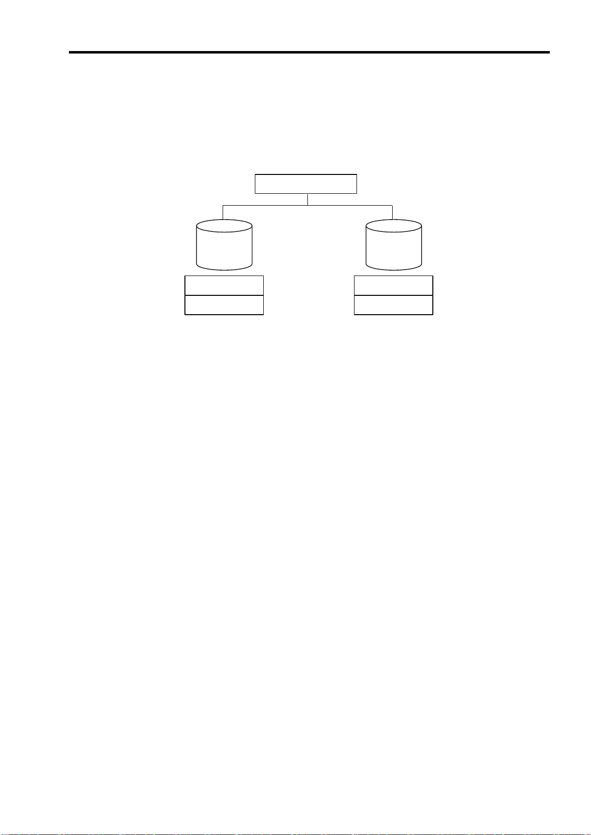
74
Disk array controller
HDD 0
HDD 1
Stripe 1
Stripe 2
Stripe 1
Stripe 2
2-3 RAID1
In RAID1, data saved to a HDD is written to another HDD without change. This mode is called "mirroring."
When data is written to a single HDD, the same data is written to another HDD. If either of the HDD‟s fails,
the other HDD containing the same data can substitute for the failed HDD. Thus, the system can continue to
operate without interruption.
Page 95

Chapter 3 Features of Disk Array
Notice
Note the following for the rebuild:
The HDD used for rebuild should have the same capacity, rotation speed, and
standard as the failed HDD.
During rebuild, the responsiveness of the server decreases due to high load.
During rebuild, do not shutdown or reboot the server. If the server is shutdown
accidentally due to power interruption, turn on the power as soon as possible. The
rebuild is automatically restarted.
The interval from the removal of the failed HDD to the installation of a new HDD
should be 60 sec or longer.
If the hot-swap rebuild does not work, perform the manual rebuild.
When the failed HDD is removed in a RAID1 configuration, the data redundancy is
lost. Replace with a new HDD as soon as possible and perform the rebuild process.
Controller
This chapter describes the features of the disk array controller.
1. Rebuild
If a HDD fails, the rebuild feature can recover the data on the failed HDD. The access lamp on the failed
HDD lights amber. The rebuild can be applied to redundant virtual disks in RAID1 after the failed HDD is
replaced. While rebuilding, the access lamp on the replaced HDD flashes.
75
1-1 Manual Rebuild
The manual rebuild can be performed by using MegaRAID Storage Manager
is the management utility of the disk array controller. Select a HDD and start the rebuild manually.
For the detailed operation, refer to the "MegaRAID Storage Manager User's Guide" on the NEC
EXPRESSBUILDER CD-ROM that comes with the server.
TM
(called MSM hereafter), which
1-2 Auto Rebuild
The disk array controller can automatically start the rebuild without using a utility such as MSM.
The auto rebuild includes:
Hot-swap rebuild
When the failed HDD is hot-swapped with a new HDD, the auto rebuild is automatically performed.
Page 96

76
Notice
Note the following for the patrol read:
The patrol read feature is factory-set to "Disabled."
To utilize patrol read, MSM must be installed.
If the system is restarted, the patrol read is aborted. After restart of the
system, the patrol read runs from the first step (top of HDD).
For the detailed operation, refer to the "MegaRAID Storage Manager
User‟s Guide" on the NEC EXPRESSBUILDER CD-ROM that comes
with the server.
Notice
Note the following for the consistency check:
During the consistency check, the responsiveness of the server
decreases due to high load.
If the system is restarted, the consistency check is aborted. However,
the consistency check resumes after restart.
For the detailed operation, refer to the "MegaRAID Storage Manager
User‟s Guide" on the NEC EXPRESSBUILDER CD-ROM that comes
with the server.
2. Patrol Read
Patrol read performs a read & verify test on the entire area of the HDD. It can be performed for all HDD‟s
assigned to virtual disks and hot-spare disks.
Patrol read allows defects of the HDD‟s to be detected and repaired.
For HDD‟s configuring redundant virtual disks or those assigned to hot-spare disks, error sectors detected
during patrol read can be repaired.
3. Consistency Check
Consistency check is used to check the consistency among virtual drives. It is available for redundant virtual
drives in RAID1.
Consistency check can be performed through WebBIOS or MSM.
Consistency check also repairs error sectors. Accordingly, it can be used for preventive maintenance.
4. Background Initialize (BGI)
Unsupported.
Page 97

5. Reconstruction
Before execution
After execution
Description
RAID level
Number of HDD’s
RAID level
Number of HDD’s
RAID0
1
RAID1
2
Capacity remains unchanged.
Notice
Note the following for the reconstruction:
Be sure to make a backup copy of data before starting reconstruction.
Reconstruction is disabled in a configuration where several virtual disks are defined in
one disk group
During reconstruction, the responsiveness of the server decreases due to high load.
Reconstruction is disabled for a degraded virtual disk. First, execute rebuild to recover
the virtual disk, and then execute reconstruction.
During reconstruction, do not shutdown or reboot the server. If the server is shutdown
accidentally due to power interruption, turn on the power as soon as possible.
Reconstruction is automatically restarted.
The reconstruction feature is used to change the configuration and/or RAID level of an existing virtual disk.
Reconstruction contains the following three features; however, the disk array controller supports "Migration
with addition" only.
5-1 Removed physical drive
Unsupported.
5-2 Migration only
Unsupported.
77
5-3 Migration with addition
Use this feature to add HDD‟s to an existing virtual disk. In MSM, this feature is indicated as "Add Drive." The
execution patterns are as shown below:
Page 98

78
36GB
[Before execution]
Capacity = 36GB
Virtual disk (RAID0)
36GB
36GB
36GB
Execute Migration with addition
Virtual disk (RAID1)
[After execution]
Capacity = 36GB
Ex: Migration with addition for RAID0 virtual disk
The figure below shows an example of adding a single 36GB HDD to a RAID0 virtual disk configured with a
single 36GB HDD:
Page 99

Chapter 4 Hardware Setup
Check
Before installation, always refer to the User‟s Guide of the server. The job
flow varies depending on the server type or system configuration. Check
the server type and system configuration before installation to perform the
setup correctly.
Start setup.
Prepare for setup.
Install the disk array controller.
Connect internal cables.
Install HDD.
Power on the server.
Configure BIOS of the server.
Run Web BIOS.
Create Virtual Disk.
Check Consistency.
Finish setup.
Install the disk array controller in a server in the following procedure.
79
Page 100

80
Notice
Note the following before the setup:
Only a single disk array controller can be installed in a server.
Some limitations may be imposed on the installation to the mezzanine slot depending
on the type of the server. Before installation, check the limitations by referring to the
User‟s Guide of the server. Only a single Type 2 Mezzanine card can be installed in a
server.
HDD‟s to be connected to the disk array controller should have the same
specifications. Contact your service representative for HDD‟s which can be
connected to the disk array controller.
Coexistence with other mezzanine cards (e.g., LAN controller, SCSI controller, etc.)
may be limited. Before using the disk array controller with other mezzanine cards,
ask your service representative whether the disk array controller can coexist with
them.
Check
Refer to the User's Guide of the server to install or remove components including the
side cover.
1. Prepare for Setup
1. Exit all applications and shutdown the OS.
2. Press the POWER switch on the server to turn off the power of the server.
3. Completely remove the server from the Blade Enclosure.
4. Remove the side cover and several components on the server.
 Loading...