

Page 1

USERS_GUIDE_1080XD_hw
H
H
H
a
a
a
r
r
r
d
d
d
w
w
w
a
a
a
r
r
r
e
e
e
G
G
G
u
u
u
i
i
i
d
d
d
e
e
e
1-1
Page 2

USERS_GUIDE_1080XD_hw
1.1 FEATURES OF EXPRESS SERVER
The Express server has as the following features.
High performance
• 64-bit Intel® Itanium® 2 processor
- 1.3-/1.4-/1.5-GHz clock
- 6.4-GB/s system bus
- 3-/4-/6-MB on-chip L3 cache
- Large capacity memory addressing
- Simultaneous six instructions
- Floating operations with standalone peak performance of 3.6/4.0 GFLOPS
• Developing a high-performance chip set and crossbar interconnect that is fully utilising
supercomputer and mainframe technology.
High reliability
• Memory monitoring function (1-bit error correction/2-bit error detection available)
• Memory mirroring function
• Bus parity error detection
• Temperature detection
• Anomaly alarming
• Power supply unit and fan redundant function (Host swap supported)
High scalability
• Expandable up to 8 CPUs
• Large-size memory up to 64 GB
• Abundant number of IO optional slots
- 64bit 66MHz PCI bus (16 slots max. including a full-size PCIF unit)
- 64bit 133MHz PCI bus (10 slots max. including a full-size PCIF unit)
• PCI hot plug supported (varies depending on the slot)
Flexible operations
• Segmentation by the unit of 4 CPUs is available.
• Each subsystem (partition) is completely independent, offering individual OS operations.
Self-check function
• Power On Self-Test (POST)
1-2
Page 3
USERS_GUIDE_1080XD_hw
1.2 NAME AND FUNCTION OF BLOCKS
Name of each block of the server is as follows.
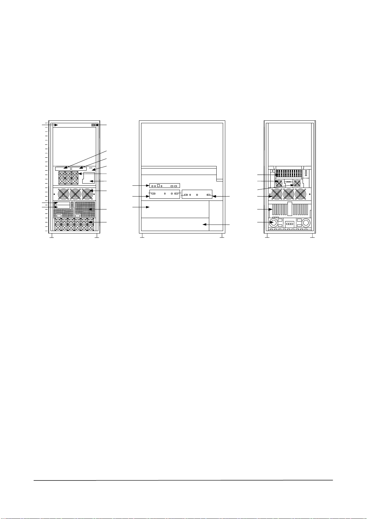
1.2.1 Main Cabinet
8Way cabinet
③-1
③-2
25
20
15
10
5
①-1 ①
②-4
②-5
②
②-7
②-6
②-9
③-3
②-2
②-1
③
正面 背面
②-1
②-3
②-8
②-8
②-9
③-4
0
Front view
(without front bezel)
④
④
View from the right side
(transparent)
④
Rear view
(cabinet back door opened)
1-3
Page 4

USERS_GUIDE_1080XD_hw
(1) Switch pannel
(1)-1 AC switch
(2) Main chasis
(2)-1 CELLV board
(2)-2 iSP-C card
Main chasis AC power switch
The CELLV board consists of a maximum of four Itanium2, one CPU Node
Controller (CNC), and a maximum of two Main Memory Controller
(MMC).Up to one CELLV board and two CELLV boards can be installed in
the 4Way main cabinet and 8Way main cabinet, respectively.
iSP-C (service processor) card has an I/O interface (except for 1.6G interface)
in the basic processing device of the Express server as a standard. This iSP-C
card is installed in the main chasis of the main cabinet.
The following standard I/O interfaces are provided by an iSP-C card. The
interfaces from 1 to 3 are dedicated interfaces used to implement the system
control function and the RAS function.
1. 10/100BASE-TX Ethernet interface x1 for SP console
2. ICMB port x1 for IO cabinet control
3. Serial (RS-232C) interface x1 for SP console
(2)-3 Core module
Up to 12 PCI cards can be installed in the core module. Additionally, a BaseIO
card, which is used to support standard optional I/O interface, can be installed
in the core module.
(2)-4 DVD-ROM Drive
DVD-ROM and CD-ROM media can be used as DVD-ROM Device.
(2)-5 Floppy Disk Drive
1-4
Floppy Disk Medium can be used as Floppy Disk Drive.
(2)-6 Magnetic Disk Drive
Up to four 36.3 GB-73.2 GB Magnetic Disk Drives can be installed.
(2)-7 Power module
Page 5

USERS_GUIDE_1080XD_hw
(2)-8 FANBOX (Core module)
(2)-9 FANBOX (Main chasis)
(3) Full-size PCIF unit
A full-size PCIF unit can be installed in an 8Way chassis as an option. Up to 14 PCI
cards can be installed in a full-size PCIF unit. Also, one BaseIO card and one VGA
card can be installed in a full-size PCIF unit to support a standard option I/O interface.
Installed PCI cards can be inserted/ejected (hot-swapped) online except for some types
of PCI cards (BaselO card/VGA card). That means it is not necessary to shut down or
FANBOX can be maintained online without aborting the system or turning off
the power.
FANBOX can be maintained online without aborting the system or turning off
the power.
reboot the basic processing device at the time of adding/exchanging PCI cards, which
leverages a high availability (a corresponding OS is required). A DVD-ROM device is
installed as default in the full-size PCIF unit. Up to six magnetic disks can be installed
as optional auxiliary memory devices.
(3)-1 DVD-ROM Drive (Optional)
DVD-ROM and CD-ROM media can be used as DVD-ROM Device.
(3)-2 Floppy Disk Drive
Floppy Disk Medium can be used as Floppy Disk Drive (which can be
connected to a full-size PCIX unit installed with a BaseIO card).
(3)-3 Magnetic Disk Drive (Optional)
Up to six 36.3GB-73.2GB Magnetic Disk Drives can be installed.
(3)-4 Slot for expanded PCI card (14 slots)
(4) Power Bay Unit
This unit supply DC power to the optional Full-size PCIX unit.
1-5
Page 6
USERS_GUIDE_1080XD_hw
1.2.2 LED Display
This shows LED description of each card.
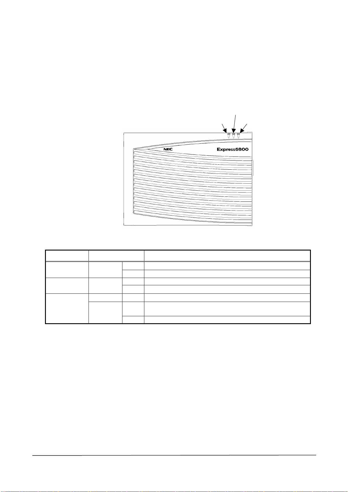
1.2.2.1 Main chasis
DC ON/OFF
AC ON/OFF
Status LED
LED name LED status Function
ON AC ON AC ON/OFF
OFF AC OFF
ON DC ON (ON at 48 V) DC ON/OFF
OFF DC OFF
ON Used for cabinet position checking during the maintenance mode
(through SP command cm) or maintenance
OFF Upon troubles or at off-line
Status LED
Green
Green
Green ON OS Ready for more than one node
Amber
1-6
Page 7
USERS_GUIDE_1080XD_hw
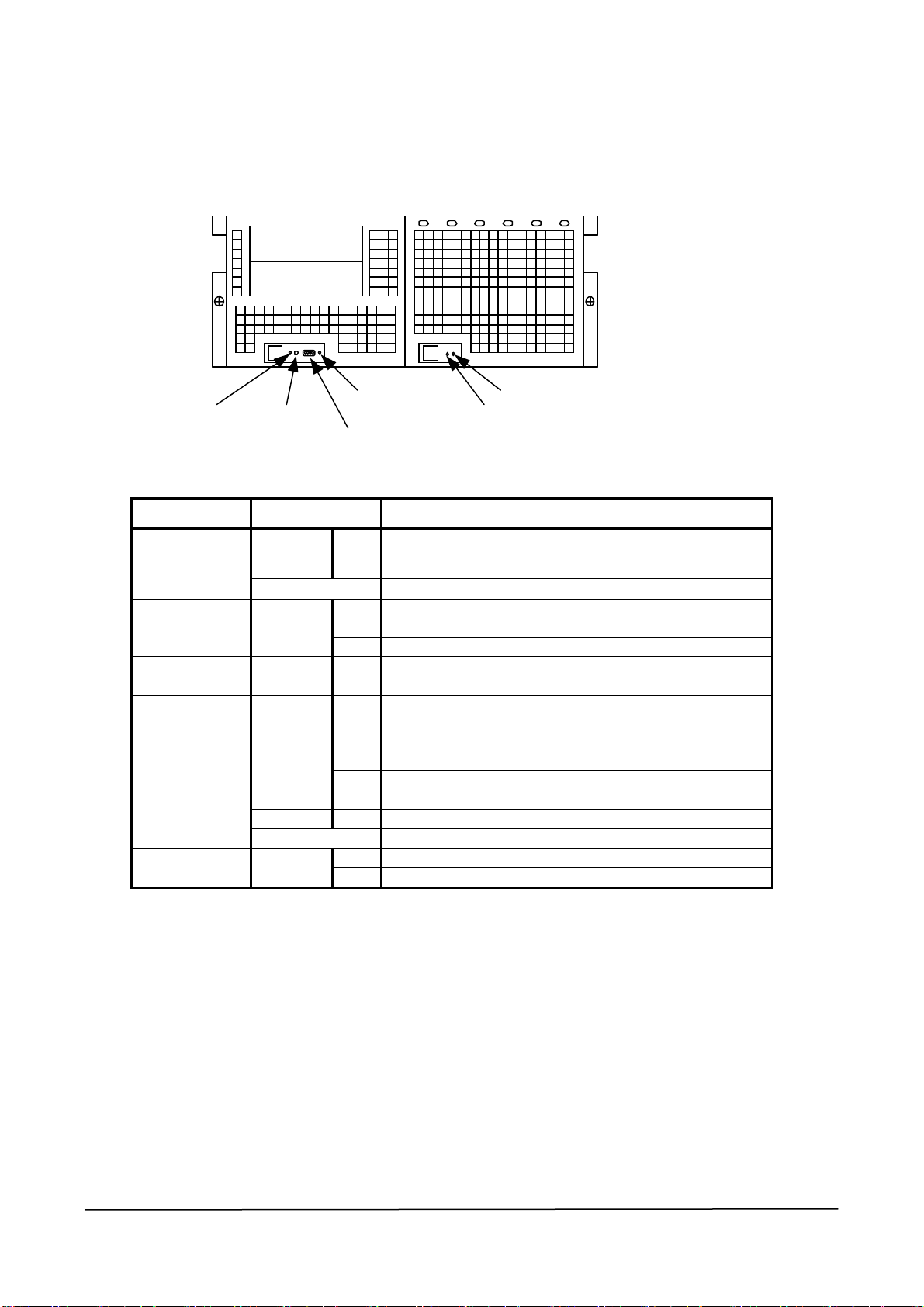
1.2.2.2 Full-size PCIX unit (without frot bezel)
DC/ALM ATT
TEMP_ALM
DC/ALM(Device Bay)
FAN_ALM(FAN#0,FAN#1,FAN#2,FAN#3)
LED Name LED Status Description
Green ON DC ON Status
TEMP_ALM(Device Bay)
DC/ALM
TEMP ALM Amber
FAN ALM Amber
ATT Amber
DC/ALM
(Device Bay)
(Device Bay)
Amber ON DC Alarm
Off DC OFF (full-size PCIX unit exchangeable)
ON
OFF Normal Status
ON FAN Rotating Status
OFF Normal Status
ON
OFF Normal Status
Green ON DC ON Status
Amber ON DC Alarm
OFF DC OFF
Amber
ON Abnormal temperature TEMP ALM
OFF Normal Status
Abnormal temperature (detected by the temperature sensor of
the IOR /PCIFB)
Full-size PCIX unit trouble (Logic alarm + DC alarm +
TEMP alarm + FAN alarm) or ON indication from SPFW
Turned on by the “led” execution of the “hc” subcommand of
the SP command
1-7
Page 8

USERS_GUIDE_1080XD_hw
1.3. INSTALLATION AND CONNECTION
1.3.1 Installation of Rack
A maintenance engineer installs a rack.
1.3.2 Installation/Removal of Cabinet
A maintenance engineer installs/removes a cabinet to/from a rack.
1.3.3 Connection
A maintenance engineer connects the Express sever and the peripheral devices.
1-8
Page 9
USERS_GUIDE_1080XD_hw
1.4. BASIC OPERATION
1.4.1 System Boot/Shutdown
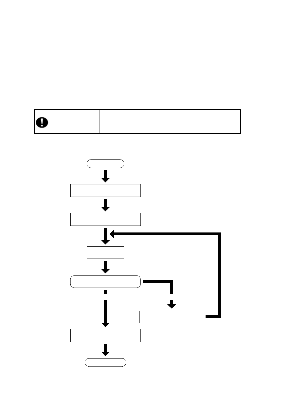
1.4.1.1 Steps for system boot
After installtion is completed (including the peripheral devies), you can boot the system
according to the following steps.
Before booting the system, please confirm all I/O devices and tools are
upgraded and installed.
Caution
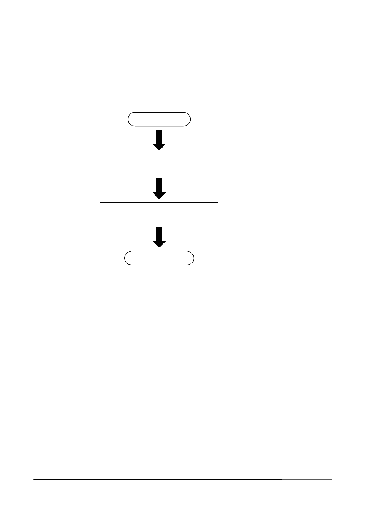
Flow of boot-up
Start
スタート
Power ON
(Refer to 1.4.1.1.1 Power ON)
(1.4.1.1.1 電源の ON 参照)
SP console operations
(1.4.1.1.2 SP Console Operations)
(1.4.1.1.2 SP コンソール操作 参照)
電源 ON
SP コンソール操作
POST
POST
(1.6 POST)
1.6.POST 参照
システム BIOS
Do you set up System BIOS?
いますか?
Ye sNo
BIOS setup (Refer to
BIOS Setup
EFI Boot menu
EFI Boot メニュー
(1.4.10 EFI Boot manager)
(1.4.10 EFI Boot マネージャ参照)
OS boot-up
OS 起動
1.4.9 System Configuration)
(1.4.9 システムコンフィグレーション 参照)
1-9
Page 10

USERS_GUIDE_1080XD_hw
1.4.1.1.1 Power ON
This server has a different power-up procedure for AC and DC. When activating from the
AC power, follow the steps below.
1. Turn on the distribution board.
2. Turn on the power of the control PC (applicable only in Japan).
3. Turn on the AC breaker in the power receptacle box in the main chasis.
4. Turn on the power of the uncontrollable external peripheral devices from the main
cabinet and confirm they have been booted without errors.
5. When a full-size PCIX unit is attached, turn on the AC power breaker of PowerBay on
the bottom of the back of the main cabinet.
6. Turn on the AC switch in the switch box located at the top in the front panel of the
cabinet.
At this moment, the DC power remains off. The DC power should be turned on the SP
console.
1-10
Page 11

USERS_GUIDE_1080XD_hw
1.4.1.1.2 SP console operations
After turning on the AC power breaker, boot the system on the SP console of the control PC.
This section describes the steps to boot the system. For details about the SP console, please
refer to 1.4.7 Service Processor (SP).
1. After opening the SP console, automatic log-in starts.
<<< Connected Line.>>>
iSP Manager Login:
root
password:
GSP>
co
Please select console number:
S0
iSP0m> S
***** SP Command Mode *****
***** enter ESC to do the command input effectively *****
***** enter CTRL+B to quit *****
2. After entering CTRL+B, the iSP first menu appears.
***** returned from SP command mode *****
iSP MAIN MENU
0) OS(BIOS) serial console of partition#0 (POWER OFF )
1) OS(BIOS) serial console of partition#1 (NOT CONFIGURED )
2) OS(BIOS) serial console of partition#2 (NOT CONFIGURED )
3) OS(BIOS) serial console of partition#3 (NOT CONFIGURED )
4) OS(BIOS) serial console of partition#4 (NOT CONFIGURED )
5) OS(BIOS) serial console of partition#5 (NOT CONFIGURED )
6) OS(BIOS) serial console of partition#6 (NOT CONFIGURED )
7) OS(BIOS) serial console of partition#7 (NOT CONFIGURED )
V) Virtual System Operator Panel
S) iSP commands
E) Exit
DISCONNECTALL) disconnect all console connections
iSP0m>
1-11
Page 12

USERS_GUIDE_1080XD_hw
3. Enter “s” of the iSP commands.
iSPyz> s<ENTER>
***** SP Command Mode *****
***** enter ESC to do the command input effectively *****
***** enter CTRL+B to quit *****
4. Enter the ESC key.
5. Enter “up” on the SP console.
iSPyz: ---> up<ENTER>
This command will bring up the specified partition.
Enter partition number (0-7/all/CR=exit) : all
Execute OK? (y/[n]) y
UP command was accepted. All partitions will run soon.
[iSPyz: INFO.ccc] partition 0 : power on sequence started.
[iSPyz: INFO.ccc] partition 1 : power on sequence started.
:
[iSPyz: INFO.ccc] partition 1 : power on sequence completed normally.
:
[iSPys: INFO.ccc] partition 1 : handed off the control to BIOS.
<ENTER>
<ENTER>
1-12
Page 13
USERS_GUIDE_1080XD_hw
1.4.1.2 Steps for system shutdown
This section describes the steps to shutdown the system.
Flow of shutdown
(1.4.1.2.1 OS シャットダウン参照)
OS シャットダウン
(Refer to 1.4.1.2.1 OS shutdown)
(Refer to 1.4.1.2.3 Power OFF)
(1.4.1.2.3 電源のOFF 参照)
Start
スタート
OS shutdown
Power OFF
電源OFF
Shutdown
立ち下げ完了
1.4.1.2.1 OS shutdown
Please refer to the OS manual and shutdown the system according to the correct steps.
1-13
Page 14

USERS_GUIDE_1080XD_hw
1.4.1.2.2 Confirmation of DC power off
Please confirm the SP console shows the following screen.
>> SP LOG MESSAGE START (07: 6K) <<
05/29/2003 19: 21: 54 0------- SP detected the completion of OS shutdown.
>> SP LOG MESSAGE END <<
>> SP LOG MESSAGE START (07: 6M) <<
05/29/2003 19: 21: 54 0------- System shutdown started. (SPFW: R05.21)
>> SP LOG MESSAGE END <<
[iSP0m: INFO.0701] partition 0 : power off sequence started.
[iSP0m: INFO.0725] partition 0 : turning off CELL(s)...
[iSP0m: INFO.0726] partition 0 : turning off PCIX(s)...
[iSP0m: INFO.0727] partition 0 : turning off XBC(s)...
[iSP0m: INFO.0718]
**************************************************
* Waiting 2 minutes for cooling components. *
* DC power is still active. *
**************************************************
* DO NOT turn off AC power. *
**************************************************
[iSP0m: INFO.0728] partition 0 : turning off PBAY(s)...
>> SP LOG MESSAGE START (07: 6M) <<
05/29/2003 19: 24: 05 0------- System shutdown completed. (SPFW: R05.21)
>> SP LOG MESSAGE END <<
[iSP0m: INFO.0703] partition 0 : power off sequence completed normally.
[iSP0m: INFO.0771]
**************************************************
* All DC power has been turned off. *
* You can turn off AC power. *
**************************************************
1-14
Page 15

USERS_GUIDE_1080XD_hw
1.4.1.2.3 Power off
After confirming the DC power is off (1.4.1.2.2), you can turn off the AC power. This
section describes the steps to turn off the AC power.
1. Turn off the AC switch in the switch box located at the top in the front panel of the
cabinet.
2. When a full-size PCIX unit is attached, turn off the AC power breaker of PowerBay on
the bottom of the back of the main cabinet.
3. Cut off the power of the uncontrollable external peripheral devices from the main
cabinet.
4. Turn off the AC power breaker in the receptacle box in the main chasis.
5. Turn off the power of the control PC (only domestically).
6. Turn off the distribution board.
1.4.2 Dump Extraction
In case of a trouble, please run the following command from the control PC to extract dump.
iSPyz: ---> dp<ENTER>
For details about the command, please refer to 1.3.6.5.3. DP (System Dump) of the
Hardware volume.
1-15
Page 16

USERS_GUIDE_1080XD_hw
1.4.3 OS Boot
Booting up the BIOS activates EFI BOOT Manager automatically.
1.4.3.1 OS boot from EFI boot manager
After installing OS, the OS Boot option is automatically registered to EFI Boot Manager.
You can boot OS by selecting OS Boot from EDI Boot Manager.
EFI Boot Manager ver 1.10 [14.61]
Please select a boot option
Windows Server 2003, Datacenter
Acpi(PNP0A03,0)/Pci(2|1)/Ata(Secondary,Master)
Acpi(PNP0A03,0)/Pci(2|1)/Ata(Primary,Master)
EFI Shell [Built-in]
Boot option maintenance menu
Use the arrow keys to change settings.
This section describes how to use EFI Boot Manager.
Automatically added
OS Boot option
1. Select a Boot pass using the cursor keys (↑,↓).
(The highlighted item is currently selected.)
2. You can boot the OS by pressing the Enter key.
1-16
Page 17
USERS_GUIDE_1080XD_hw
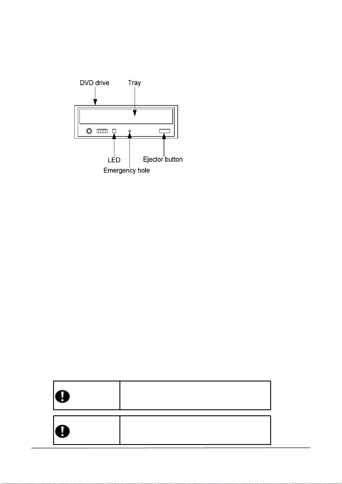
1.4.4 DVD-ROM Drive
1.4.4.1 Insert/eject to/from DVD-ROM drive
(1) How to insert DVD-ROM/CD-ROM
1) Touch on the ejector button to open the tray.
2) Place the DVD-ROM/CD-ROM on the tray with the label side up.
3) Touch the ejector button to close the tray.
(2) How to eject DVD-ROM/CD-ROM
1) Confirm the access display LED (orange) on the DVD-ROM drive is on.
2) Touch on the ejector button.
3) Touch on the ejector button to open the tray.
4) Eject DVD-ROM/CD-ROM from the tray.
5) Touch the ejector button to close the tray.
(3) How to eject DVD-ROM/CD-ROM when the tray does not open after touching the
ejector button
1) Confirm the DC/ALM LED on the PCI box is off.
2) Insert a long and thin metal bar such as a clip into the emergency hole.
3) After the tray opens slightly, pull out the tray.
4) Eject DVD-ROM/CD-ROM from the tray.
Caution
Caution
1-17
Be careful not to pinch your hands in the tray. It may cause an
injury.
Be careful not to hurt your figures when inserting a thin metal
bar into the emergency hole.
Page 18
USERS_GUIDE_1080XD_hw
DVD drive
Button
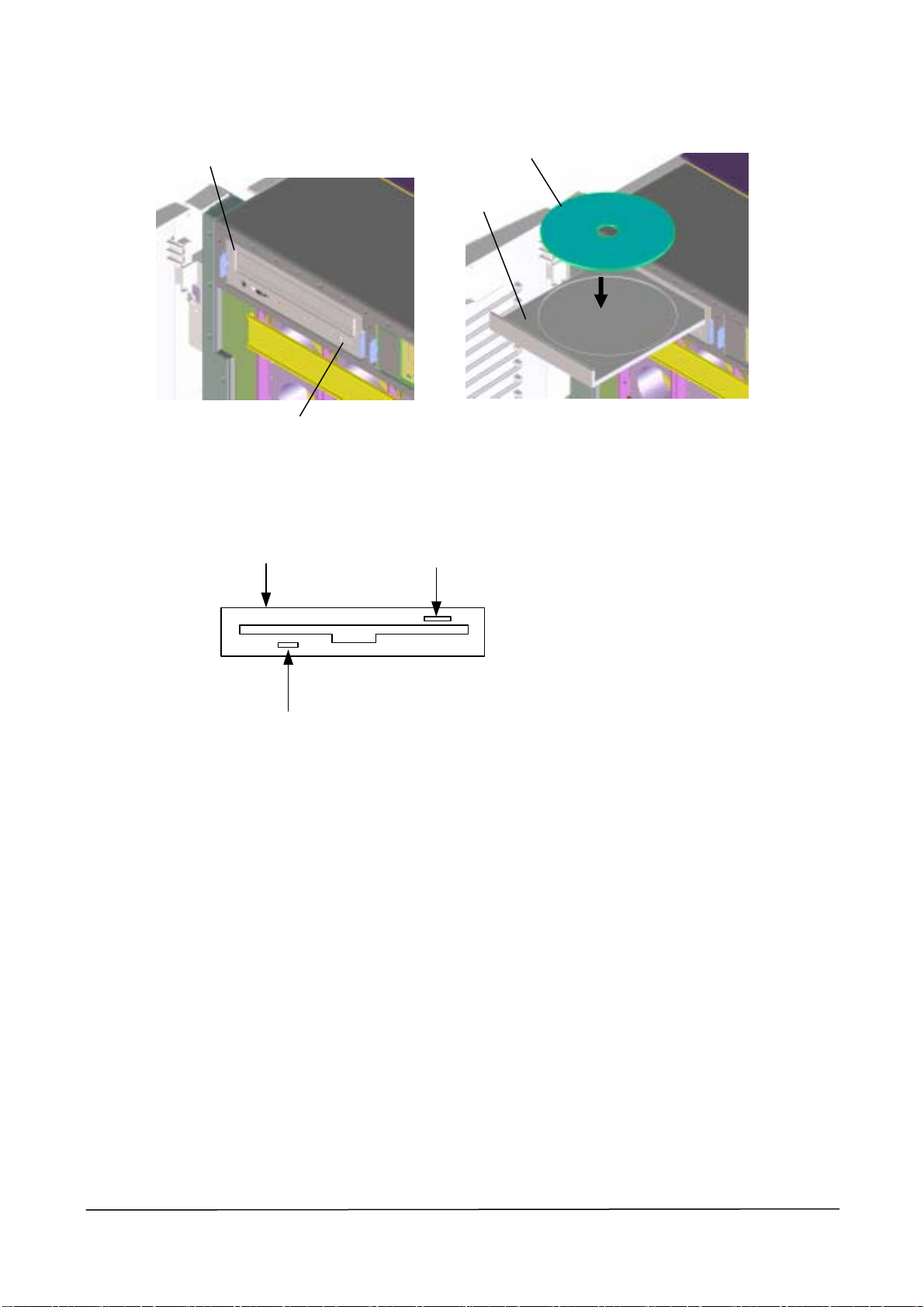
1.4.5 Floppy Disk Drive
Floppy disk drive Ejector button
DVD
Tray
LED
(1) How to insert a disk into the floppy disk drive
1) Press a floppy disk into the floppy disk drive.
2) You hear a clicking sound, and the ejector button of the floppy disk drive is slightly
pushed out.
(2) How to eject a floppy disk
1) Confirm the access display LED (orange) on the floppy disk drive is off.
2) Touch on the ejector button to eject the floppy disk from the floppy disk drive.
1-18
Page 19
USERS_GUIDE_1080XD_hw
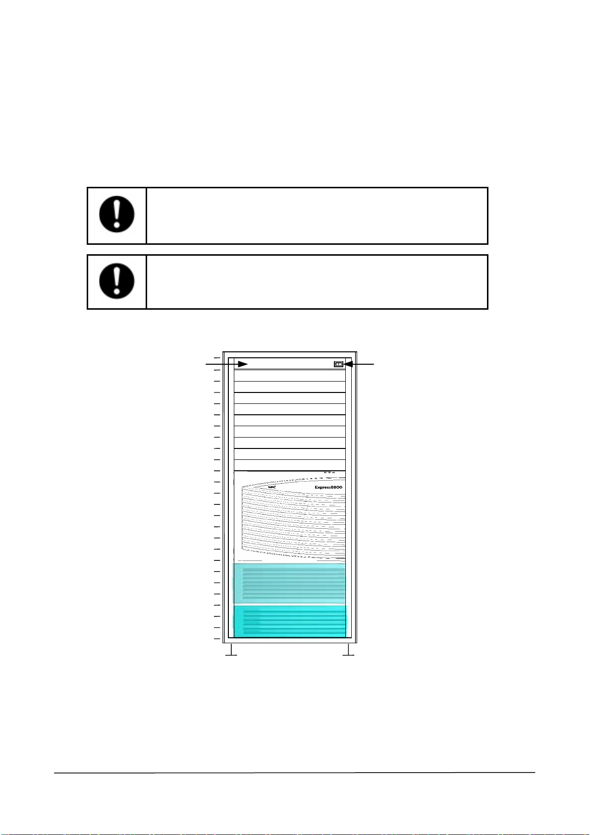
1.4.6 AC Switch (in emergency situation)
The AC switch is used at start or shutdown of a unit and steps should be followed. In case of
emergency that must cut the power for the unit, you can turn off the AC switch. Never turn
off the AC switch during the normal operation.
Data may be destroyed if the AC switch is turned off without executing correct
shutdown steps.
Users should make a guideline for emergency shutdown thorugh the AC
switch.
Switch Panel
25
20
15
10
AC Switch
5
0
1-19
Page 20
USERS_GUIDE_1080XD_hw
1.4.7 Service Processor (SP)
The basic processing device of the Express server has the interfaces to provide users with an
advanced system control and the RAS function. These functions can be used with the
service processor (SP hereafter) in iSP.
1.4.7.1 SP console
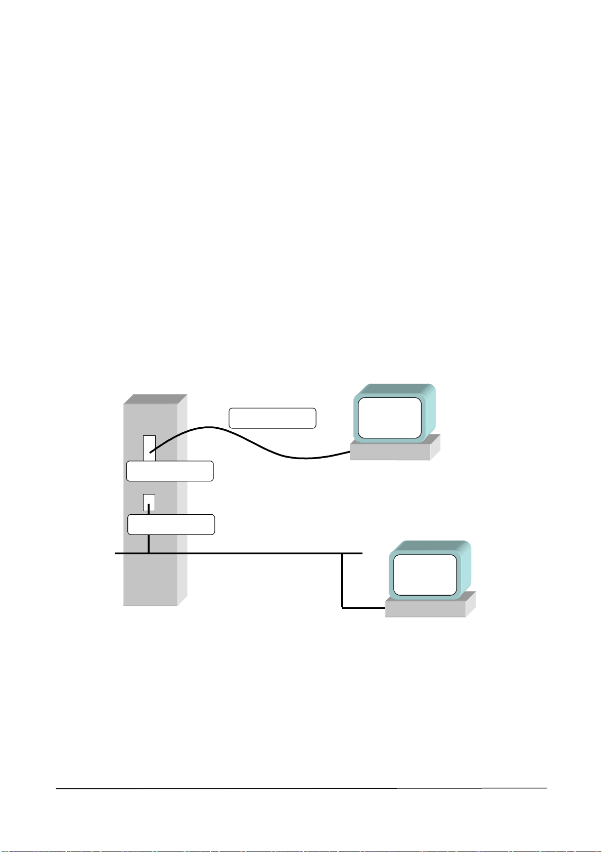
1.4.7.1.1 Type of console connection
iSP supports two types of console connections: the Local Console connected through a
serial connector and the Control PC Console connected through a LAN connector.
These two types of consoles work exactly in the same manner. However, to use the LAN
console, you can initialize the operation only on the Local Console.
For details about the serial setting and the LAN setting, please refer to the reference manual
attached to the SG command.
local
iSP - card
Serial connector 0
LAN connector
null modem cable
TCP5001
console
LAN
Control PC
console
1-20
Page 21

USERS_GUIDE_1080XD_hw
1.4.7.1.2 Operation available on the console
The following operations are available on the console.
• iSP operation by SP command
• Redirection of OS (BIOS) serial (CPU cage inbuilt) console
• Display of virtual SOP
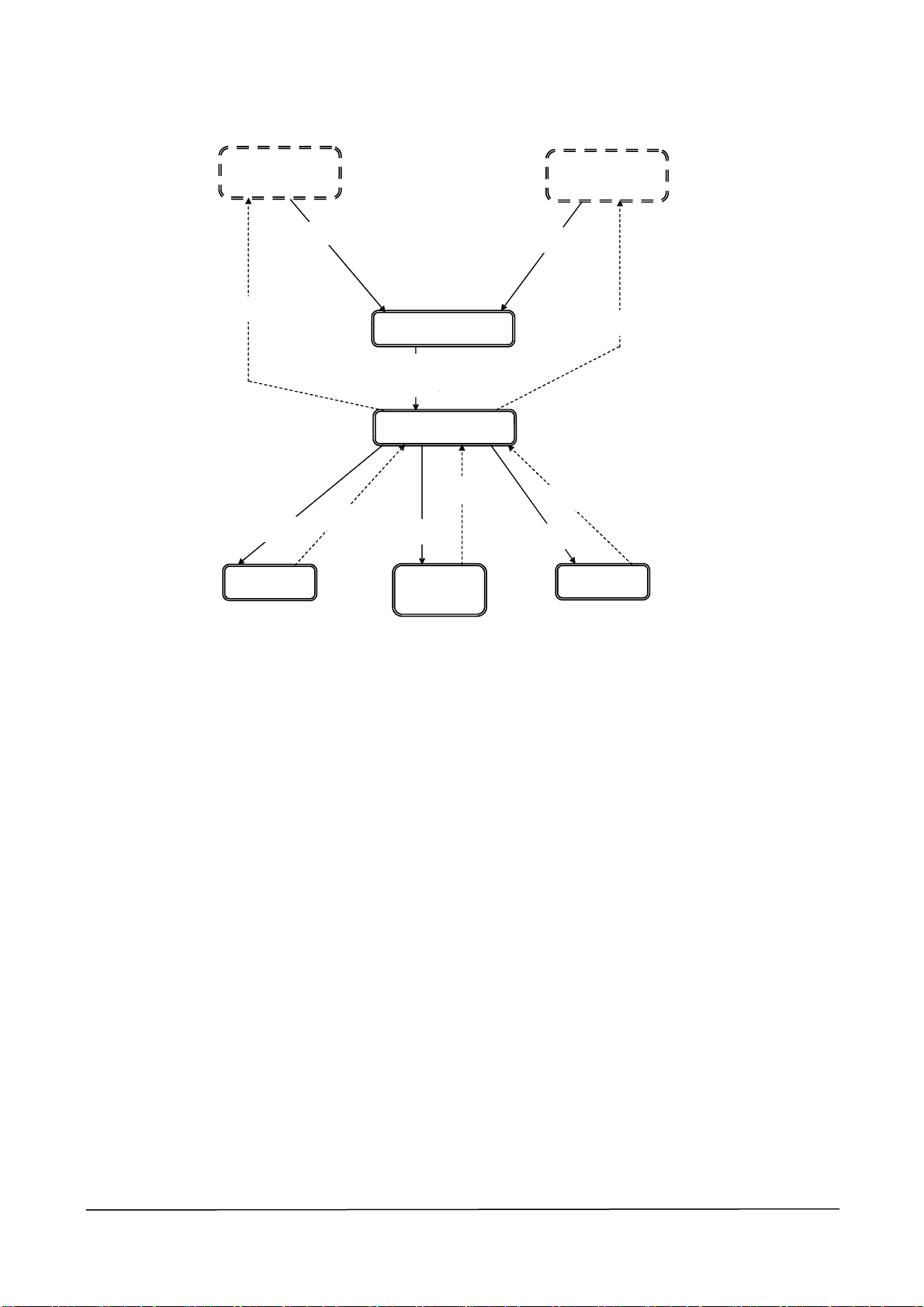
1.4.7.1.3 Console status and log in authentication
You need to log in to iSP to use the console.
After you log in to iSP, the first menu is displayed. From the first menu, you shift to “virtual
SOP”, “OS console” or “SP command console”.
• On the virtual SOP, the system operation status for each partition is displayed regularly
updated.
• On the OS console, the serial I/O, which is visible on the console, is re-directed.
• On the SP command console, you may monitor iSP output message necessary for the
system operation and the maintenance, or input a command into iSP. On the SP command
console, you may only operate commands necessary for the system operation.
You can simultaneously connect only one connection for each partition on the OS console,
up to nine connections for the entire system on the virtual SOP system, and only one
connection for the entire system on the SP command console.
1-21
Page 22
USERS_GUIDE_1080XD_hw
Serial console
(Disabled status)
TCP-5001
Control PC
未接続
unconnected
Selecting Exit
Selecting SOP
Virtual SOP
Pressing ESC
B input
iSP login prompt
Log-in password
ログイン
unnecessary
パスワード必要
First menu
^B input
Selecting SP
SP command
Normal mode
TCP5001
Control PC connected
接続
Selecting Exit
-
B input
Selecting OS
OS console
1-22
Page 23

USERS_GUIDE_1080XD_hw
1.4.7.1.4 Log in and first menu
The default status of the console connection to iSP is the log in pending status showing the
log in prompt. Enter the log in account and the password to display the first menu.
The log in account and the password are case-sensitive.
If the entered characters on the first menu are English alphabets, they are not case-sensitive.
(For example, you may use either the lower case “e” or the upper case “E”.)
(Screen Image)
Integrated Service Processor.
Cabinet-ID: xx, Location: y, State: ssssss
iSP login: spfw<ENTER>
iSP password: xxxxxxxx<ENTER>
Copyright (C) 2002 NEC Corporation, All Rights Reserved.
Welcome to Integrated Service Processor.
iSP FW version : 01.00 generated on 01/31/2002 19: 20: 33
iSP MAIN MENU
0) OS(BIOS) serial console of partition#0 (INITIALIZING )
1) OS(BIOS) serial console of partition#1 (RUNNING )
2) OS(BIOS) serial console of partition#2 (STOPPED )
3) OS(BIOS) serial console of partition#3 (FAULT )
4) OS(BIOS) serial console of partition#4 (POWER OFF )
5) OS(BIOS) serial console of partition#5 (RUNNING )
6) OS(BIOS) serial console of partition#6 (NOT CONFIGURED)
7) OS(BIOS) serial console of partition#7 (NOT CONFIGURED)
V) Virtual System Operator Panel
S) iSP commands
E) Exit
DISCONNECTALL) disconnect all console connections
iSP yz> (e)
Description
code
(a)
(b)
(c)
(d)
1-23
Page 24

USERS_GUIDE_1080XD_hw
(Description)
Description
code
(a)
(b)
(c) The version information of iSP FM is shown.
(d)
(e)
Description
xx is an ID to specify a cabinet in a system consisted of multiple cabinets.
y shows the implementation position of iSP board as 0 or 1.
ssssss shows “master” when the master is operating, “backup” when the backup is
operating, and “undetermined” when the master or the backup is not determined.
Enter the log in account and the password.
The password is not shown.
The first menu is shown.
The OS console and the virtual SOP can only be selected in iSP whose mater is
operating.
On the OS console menu, summary status of partitions are shown as well.
This is the first menu selection prompt.
y shows the implementation position of iSP board as 0 or 1.
z shows “m” when the master is operating, “b” when the backup is operating, and “u”
when the master or the backup is not determined.
1-24
Page 25

USERS_GUIDE_1080XD_hw
Possible Events (including input) and Action
Event Action
Incorrect account or password entered Display “incorrect” and then, display the log in prompt again.
Incorrect account or password entered
Cut off the connection.
three times successively
Leaving the Login or the password
Display “timeout” and then, cut off the connection.
prompt for five minutes
Character(s) not listed in the menu is
Display the menu again.
entered
Showing a menu for five minutes Display “timeout” and then, cut off the connection.
Disabled since the iSP master has
changed during displaying the menu
The menu display and the prompt are not immediately viewed.
When a disabled menu is selected, it is skipped and another new menu
is displayed.
0 to 7 Selection
(enabled only with the master iSP
S Selection
)
Shift to the OS (BIOS) serial console redirection.
Shift to the SP command console.
(enabled regardless of the master or the
backup)
V Selection
Shift to the virtual SOP.
(enabled only with the master iSP)
E Selection Cut off the connection currently in operation.
DISCONNECTALL Selection Cut off all the connections except for the connection currently
established to iSP.
This is a special operation required for a situation where any following
operation becomes disabled when a cut-off connection remains for iSP
control because a fault event has occurred in a connection client
connected to iSP.
After the selection of this event, authentication is required using the
maintenance password.
Exceed the number of connections
available on the selected menu
Display “N connections to the selected mode are already established.
Try it later. ” and then, display the first menu again.
1-25
Page 26

USERS_GUIDE_1080XD_hw
1.4.7.2 OS (BIOS) console
If you select the OS (BIOS) console on the iSO first menu, the I/O into the serial controller
visible on OS (BIOS) is re-directed. To go back to the first menu from that status, enter “^B”
(press “B” while holding CTRL).
The display images or the operations in the re-directed status depend on the BIOS and OS
operating on that particular partition and have no relation to the iSP. The OS (BIOS) console
re-direction is available only with the master iSP.
(Screen Image)
iSP MAIN MENU
0) OS(BIOS) serial console of partition#0 (INITIALIZING )
1) OS(BIOS) serial console of partition#1 (RUNNING )
2) OS(BIOS) serial console of partition#2 (STOPPED )
3) OS(BIOS) serial console of partition#3 (FAULT )
4) OS(BIOS) serial console of partition#4 (POWER OFF )
5) OS(BIOS) serial console of partition#5 (RUNNING )
6) OS(BIOS) serial console of partition#6 (NOT CONFIGURED)
7) OS(BIOS) serial console of partition#7 (NOT CONFIGURED)
V) Virtual System Operator Panel
S) iSP commands
E) Exit
DISCONNECTALL) disconnect all console connections
iSP yz> 0<ENTER>
***** redirection of serial console 0 *****
***** enter CTRL+B to quit *****
:
:
:
:
:
<CTRL>+<B>
***** returned from serial console 0 redirection ***** (e)
Description code
(a)
(b)
(c)
(d)
1-26
Page 27

USERS_GUIDE_1080XD_hw
(Description)
Description
code
(a) If you enter 0 to 7, you are re-directed to the OS console of a corresponding partition.
(b) Display the starting message for the OS console re-direction.
(c) The I/O during the OS re-direction depends on OS or BIOS.
(d) If you enter “^B”, the OS re-direction is terminated.
(e)
Possible Event (including input) and Action
Enter “^B” (CTRL+B). Display a message to leave the OS (BIOS) console,
The OS (BIOS) console becomes disabled
because the iSP master has changed.
The SP command clears the displayed
partition.
Description
Display the ending message.
Then, go back to the first menu.
Event Action
and go back to the first menu and the prompt.
Display a message to leave the OS (BIOS) console,
and go back to the first menu and the prompt.
Display a message to leave the OS (BIOS) console,
and go back to the first menu and the prompt.
1-27
Page 28

USERS_GUIDE_1080XD_hw
1.4.7.3 Virtual SOP
If you select the virtual SOP (Virtual System Operation Panel) on the first menu, the virtual
SOP is displayed. The virtual SOP displays regularly the status of the general information of
all configured partitions.
To go back to the first menu from the virtual SOP, enter “^B” (press “B” while holding
CTRL).
The virtual SOP is available only with the master iSP.
(Screen Image)
iSP MAIN MENU
0) OS(BIOS) serial console of partition#0 (INITIALIZING )
1) OS(BIOS) serial console of partition#1 (RUNNING )
2) OS(BIOS) serial console of partition#2 (STOPPED )
3) OS(BIOS) serial console of partition#3 (FAULT )
4) OS(BIOS) serial console of partition#4 (POWER OFF )
5) OS(BIOS) serial console of partition#5 (RUNNING )
6) OS(BIOS) serial console of partition#6 (NOT CONFIGURED )
7) OS(BIOS) serial console of partition#7 (NOT CONFIGURED )
V) Virtual System Operator Panel
S) iSP commands
E) Exit
DISCONNECTALL) disconnect all console connections
iSP yz> V<ENTER>
----- Virtual System Operator Panel --------- 01/31/2001,19: 30: 20 ----
xx 0 HW INITIALIZING yyyyyy xx 1 RUNNING yyyyyy
BIOS messages BIOS messages
SP messages SP messages
xx 2 STOPPED yyyyyy xx 3 FAULT yyyyyy
BIOS messages BIOS messages
SP messages SP messages
xx 4 POWER OFF yyyyyy xx 5 RUNNING
yyyyyy
BIOS messages BIOS messages
SP messages SP messages
xx 6 NOT CONFIGURED yyyyyy xx 7 NOT CONFIGURED
yyyyyy
BIOS messages BIOS messages
SP messages SP messages
----- Enter CTRL+B to quit ------------------------------------------ :
:
:
<CTRL>+<B>
Description
code
(a)
(b)
(c)
(d)
1-28
Page 29

USERS_GUIDE_1080XD_hw
(Description)
Description
code
(a) If you enter “V”, the virtual SOP is displayed.
(b) This is the virtual SOP display.
(c) During this period, the virtual SOP is displayed.
(d)
Possible Event (including input) and Action
Enter “^B” (CTRL+B). Go back to the first menu and the prompt.
The virtual SOP becomes disabled because
the iSP master has changed.
Description
If you enter “^B”, the virtual SOP is terminated.
Then, go back to the first menu.
Event Action
Display a message to leave the virtual SOP, and go back
to the first menu and the prompt.
1-29
Page 30

USERS_GUIDE_1080XD_hw
1.4.7.3.1 Detail of partition status display
A status display for each partition consists of the following sections.
1 2
3 4
5
xx N sssssssssssssss ccccc
ttttttttttttttttttttttttttttttt
uuuuuuuuuuuuuuuuuuuuuuuuuuuuuuu
(1) Number An ID to specify a cabinet in a super scalable cluster consisted of
(2) Number (0-7) A partition number.
String A string to show the status of a partition.
(3)
POWER OFF DC OFF status.
STOPPED DC On Status, no trouble, and stopped.
HW INITIALIZING Initializing HW by iSP. BIOS not booted yet.
SW INITIALIZING Initializing the system by BIOS.
Display Description
multiple cabinets.
6
RUNNING The system is initialized by BIOS and EFI succeeds.
FAULT Troubled and stopped.
SHUT DOWN Booting HW by iSP.
NOT CONFIGURED Not configured.
(4) Six Hexadecimal
Digits
(5) String There is an error code by BIOS.
(6) String There is a warning error by SP.
Latest chassis code transferred from BIOS or OS.
This is cleared when shifting to the DC OFF status.
This is cleared when shifting to the DC OFF status.
1-30
Page 31

USERS_GUIDE_1080XD_hw
1.4.7.4 SP command console
If you select the SP command on the iSP first menu, the SP command console is displayed.
To go back to the first menu from the SP command console, enter “^B” (press “B” while
pressing CTRL). Some SP commands can be only used with the master iSP.
(Screen Image)
iSP MAIN MENU
0) OS(BIOS) serial console of partition#0 (INITIALIZING )
1) OS(BIOS) serial console of partition#1 (RUNNING )
2) OS(BIOS) serial console of partition#2 (STOPPED )
3) OS(BIOS) serial console of partition#3 (FAULT )
4) OS(BIOS) serial console of partition#4 (POWER OFF )
5) OS(BIOS) serial console of partition#5 (RUNNING )
6) OS(BIOS) serial console of partition#6 (NOT CONFIGURED )
7) OS(BIOS) serial console of partition#7 (NOT CONFIGURED )
V) Virtual System Operator Panel
S) iSP commands
E) Exit
DISCONNECTALL) disconnect all console connections
iSP yz> S<ENTER>
:
:
:
:
:
<CTRL>+<B>
(Description)
Description
code
(a) If you enter “S”, the SP command console is displayed.
(b) During this period, the SP command input and the SP message output are monitored.
(c)
If you enter “CTRL+B”, the SP command console is closed and the first menu is
displayed again.
Description
code
(a)
(b)
(c)
Description
1-31
Page 32

USERS_GUIDE_1080XD_hw
1.4.7.4.1 SP command console buffer
The output of the SP command console of iSP may include some important information
such as the cause of system status change. For operation on the premises of the LAN
console, any console output cannot be monitored, which is executed between the
initialization of iSP and the establishment of the LAN console. For this reason, iSP has the
function to save certain message outputs, which is executed while the SP command console
is not established, in the buffer temporarily.
This buffer has about 1,000 lines of space and saves 1,000 lines of messages.
The content of the buffer can be displayed using the “ML” command.
1.4.7.4.2 SP command prompt
In the SP command mode, if you press the “ESC” key, a command prompt in the following
format is displayed.
Prompt Description
iSP yz: ---> Command prompt in the normal mode.
1.4.7.4.3 SP message header
Basically the SP message is output with a header in the following format.
If an interactive dialogue is executed in each SP command, all prompts or messages are not
attached with any message header.
Message Header Description
[iSP yz: INFO.cccc] string Information message.
[iSP yz: WARN.cccc] string Alert message.
[iSP yz: ERRORcccc] string Error message.
cccc is an ID attached to an individual message.
string is the message body.
1-32
Page 33

USERS_GUIDE_1080XD_hw
1.4.7.4.4 SP command list
The following list includes the SP commands in categories.
System Control
CMD Command name Function
Shut down System power
DF
(override)
DN Shut down System power
DP System Dump
PC Power Cycle
RS Cold Reset System
UP Bring up System
Save system CMOS/
SR
NvRAM
NML mode: Availability or Unavailability of operation in the normal mode. X means
The iSP turns off the DC power of the specified
partition without notifying the SW(OS) even if it is
running..
If the specified partition is in S0 state, the iSP only
generates the SCI(POWBTN). Otherwise, the iSP
turns off the DC power directly.
The iSP generates the INIT signal to the specified
partition. SW(OS) will enter its dump routine.
The iSP turns off the DC power of the specified
partition without notifying the SW(OS) even if it is
running, turns on the DC power, initializes HW
and hands off the control to the BIOS.
The iSP initializes the specified partition without
notifying the SW(OS) even if it is running.
The iSP turns on the DC power of the specified
partition and initializes HW and hands off the
control to the BIOS. The BIOS will boot the
Operating System.
Save and/or restore the system
CMOS/NvRAM.
NML
mode
iSP
state
X m
X m
X m
X m
X m
X m
X m
available.
m: Availability or Unavailability of operation in the master iSP.
(Reference) System state transition and System control commands
DN/DP
(only trigger)
DC OFF
UP/PC
DN/DF
DC ON
Not running
DF
PC
Ready
SW running
RS
UP/PC/RS
1-33
Page 34

USERS_GUIDE_1080XD_hw
1.4.7.5 SP command reference
The SP command reference describes the details about the SP command.
In the right side of the starting page of each command, availability or unavailability of
operation is shown in the normal operation, the master iSP, the backup iSP and an
undetermined iSP.
(Example)
NML: Availability or Unavailability of operation in the normal mode. X means available.
MNT: Availability or Unavailability of operation in the maintenance mode. X means
available.
NML MNT
X X
Essentially the SP command and the subcommand are not case-sensitive. For some
exceptions such as the account or the password, it is noted that they are case-sensitive if
applicable.
1-34
Page 35

USERS_GUIDE_1080XD_hw
1.4.7.5.1 DF (Power off <override>)
Function:
Turn off the DC power of the system.
Turn off the DC power of the system regardless of the operation status of OS or BIOS and
without notifying anything to OS or BIOS (which corresponds to the power button override
function in a device with a physical power button).
(Screen Image)
iSPyz: ---> df<ENTER>
CAUTION: System power will be turned off without any notice to the
softwares even if they are running.
Enter partition number (0-7/all/CR=exit) : all<ENTER>
Execute OK? (y/[n]) y<ENTER>
DF command was accepted. System power of all partitions will be turned off
soon.
[iSPyz: INFO.ccc] partition 0 : power off sequence started.
[iSPyz: INFO.ccc] partition 1 : power off sequence started.
:
:
:
[iSPyz: INFO.ccc] partition 1 : power off sequence completed normally.
(Description)
Description
code
(a)
(b)
(c)
(d) Display the operation status in the background.
Enter the partition number.
If you select “all”, all the configured partitions are set to be objects.
Display a confirmation message.
Enter “y” to continue the operation.
Display a DF command acceptance message.
Actual process operates in the background.
Description
NML MNT
X X
Available against a partition in operation
(after automatic boot/UP command
executed) or in a maintenance DC-ON.
Description
code
(a)
(b)
(c)
(d)
1-35
Page 36

USERS_GUIDE_1080XD_hw
1.4.7.5.2 DN (Shut down System Power)
Function:
Turn off the DC power of the system.
Turn off the power of the system if the software (OS, BIOS and so forth) is not operating.
If the software (OS, BIOS and so forth) is operating (S0 status), report a power button
interruption to the software and the process against the power button interruption depends
on the software (the software may ignore the power button interruption or execute the
shutdown process and turns off the power).
Sometimes power button interruption may not be processed even when iSP recognizes as
“Software Operating”. In this case, please use the DF command to force the power of the
system to be turned off.
NML MNT
X X
Available against a partition in operation
(after automatic boot/UP command
executed)
(Screen Image)
iSPyz: ---> dn<ENTER>
System power will be turned off if the software(OS) is NOT running.
Only power button interrupt will be generated if the software(OS) is running.
If you want to turned off the system power in any system state, use DF
command.
Enter partition number (0-7/all/CR=exit) : all<ENTER>
Execute OK? (y/[n]) y<ENTER>
DN command was accepted. System power of all partitions will be turned off or
power button interrupt will be ganerated soon.
[iSPyz: INFO.ccc] partition 0 : power button interrupt.
[iSPyz: INFO.ccc] partition 1 : power button interrupt.
[iSPyz: INFO.ccc] partition 2 : power off sequence started.
:
:
:
[iSPyz: INFO.ccc] partition 2 : power off sequence completed normally.
Description
(Description)
Description
code
(a)
(b)
(c)
(d) Display the operation status in the background.
Enter the partition number.
If you select “all”, all the configured partitions are set to be objects.
Display a confirmation message.
Enter “y” to continue the operation.
Display a command acceptance message.
Actual process operates in the background.
Description
code
(a)
(b)
(c)
(d)
1-36
Page 37

USERS_GUIDE_1080XD_hw
1.4.7.5.3 DP (System Dump)
Function:
Generate dump interruption in the system.
It depends on the software (OS or BIOS) to operate the dump process or execute the system
reset subsequently. This command has a sole function to generate dump interruption.
No action occurs if the software is not operating.
(Screen Image)
iSPyz: ---> dp<ENTER>
Dump button interrupt will be generated.
Enter partition number (0-7/all/CR=exit) : all<ENTER>
Execute OK? (y/[n]) y<ENTER>
DP command was accepted. Dump button interrupt will be ganeratedsoon. (c)
[iSPyz: INFO.ccc] partition 0 : dump button interrupt.
[iSPyz: INFO.ccc] partition 1 : dump button interrupt.
:
:
:
(Description)
Description
code
(a)
(b)
(c)
(d) Display the operation status in the background.
Enter the partition number.
If you select “all”, all the configured partitions are set to be objects.
Display a confirmation message.
Enter “y” to continue the operation.
Display a command acceptance message.
Actual process operates in the background.
Description
NML MNT
X X
Available against a partition in operation
(after automatic boot/UP command
executed)
Description
code
(a)
(b)
(d)
1-37
Page 38

USERS_GUIDE_1080XD_hw
1.4.7.5.4 PC (Power Cycle)
Function:
Cut off the DC power of the system and restore the power to boot the system.
Cut off the power of the system regardless of the operation status of OS or BIOS and
without notifying anything to OS or BIOS.
(Screen Image)
iSPyz: ---> pc<ENTER>
CAUTION: System power will be turned off without any notice to the softwares
even if they are running.
Enter partition number (0-7/all/CR=exit) : all<ENTER>
Execute OK? (y/[n]) y<ENTER>
PC command was accepted. System power of all partitions will be turned off soon
and then will be turned on.
[iSPyz: INFO.ccc] partition 0 : power off sequence started.
[iSPyz: INFO.ccc] partition 1 : power off sequence started.
:
[iSPyz: INFO.ccc] partition 1 : power off sequence completed normally.
:
[iSPyz: INFO.ccc] partition 0 : power on sequence started.
[iSPyz: INFO.ccc] partition 1 : power on sequence started.
:
[iSPyz: INFO.ccc] partition 1 : power on sequence completed normally.
:
[iSPys: INFO.ccc] partition 1 : handed off the control to BIOS.
(Description)
Description
code
Enter the partition number.
(a)
(b)
(c)
(d) Display the operation status in the background.
If you select “all”, all the configured partitions are set to be objects.
However, a partition, which has already been Power OFF, cannot be an object.
Display a confirmation message.
Enter “y” to continue the operation.
Display a DF command acceptance message.
Actual process operates in the background.
Description
NML MNT
X X
Available against a partition in operation
(after automatic boot/UP command
executed)
Description
code
(a)
(b)
(c)
(d)
1-38
Page 39

USERS_GUIDE_1080XD_hw
1.4.7.5.5 RS (Cold Reset System)
Function:
Cold reset the system.
Execute reset regardless of the operation status of OS or BIOS and without notifying
anything to OS or BIOS.
(Screen Image)
iSPyz: ---> rs<ENTER>
CAUTION: System will be resetted without any notice to the softwares even if
they are running.
Enter partition number (0-7/all/CR=exit) : all<ENTER>
Execute OK? (y/[n]) y<ENTER>
RS command was accepted. All partitions will be resetted soon. (c)
[iSPyz: INFO.ccc] partition 0 : initializing HW.
[iSPyz: INFO.ccc] partition 1 : initializing HW.
:
:
:
[iSPyz: INFO.ccc] partition 0 : handed off the control to BIOS.
[iSPyz: INFO.ccc] partition 1 : handed off the control to BIOS.
(Description)
Description
code
Enter the partition number.
(a)
(b)
(c)
(d) Display the operation status in the background.
If you select “all”, all the configured partitions are set to be objects.
However, a partition, which has already been Power OFF, cannot be an object.
Display a confirmation message.
Enter “y” to continue the operation.
Display a RS command acceptance message.
Actual process operates in the background.
Description
NML MNT
X X
Available against a partition in operation
(after automatic boot/UP command
executed)
Description
code
(a)
(b)
(d)
1-39
Page 40

USERS_GUIDE_1080XD_hw
1.4.7.5.6 UP (Bring up System)
Function:
Turn on the DC power of the system and initialize HW to boot BIOS.
After this, whether OS is to be booted or not depends on the setting of BIOS/EFI.
(Screen Image)
iSPyz: ---> up<ENTER>
This command will bring up the specified partition.
Enter partition number (0-7/all/CR=exit) : all<ENTER>
Execute OK? (y/[n]) y<ENTER>
UP command was accepted. All partitions will run soon. (c)
[iSPyz: INFO.ccc] partition 0 : power on sequence started.
[iSP
yz: INFO.ccc] partition 1 : power on sequence started.
:
[iSP
yz: INFO.ccc] partition 1 : power on sequence completed normally.
:
[iSP
ys: INFO.ccc] partition 1 : handed off the control to BIOS.
(Description)
Description
code
(a)
(b)
(c)
(d) Display the operation status in the background.
Enter the partition number.
If you select “all”, all the configured partitions are set to be objects.
Display a confirmation message.
Enter “y” to continue the operation.
Display a UP command acceptance message.
Actual process operates in the background.
Description
NML MNT
X X
Available against a partition not in
operation (in the DC-OFF status)
Description
code
(a)
(b)
(d)
1-40
Page 41

USERS_GUIDE_1080XD_hw
1.4.7.5.7 SR (Save system CMOS/NvRAM)
Function:
Read out the CMOS/NvRAM content of the system and save them on a FTP server, or
alternately restore from the files on a FTP server.
The object partition must be in the EFI shell prompt after BIOS is booted. Otherwise, a
proper operation is not assured, besides it may corrupt the CMOS/NvRAM content.
(Screen Image)
iSPyz: MNT> sr<ENTER>
CAUTION: This command MUST be used when target system is in EFI
shell prompting. Otherwise CMOS/NvRAM may be DESTROYED or this com
mand do NOT work properly.
Enter partition number? (0-7/CR=exit) : 1<ENTER>
Save of Restore? (s/r/CR=back) : s<ENTER>
getting CMOS/NvRAM from partition 1...
got.
ERROR: cannot get CMOS/NvRAM from partition 1. Check the state of p
artition 1.
Enter partition number? (0-7/CR=exit) :
IP of FTP server [default=10.0.0.2] (CR=skip) : 10.0.0.3<ENTER>
account [default=necuser] : necuser<ENTER>
password [default=********] : xxxxxxxx<ENTER>
file path : cmossave/cmos1.bin<ENTER>
Save OK? (y/[n]) : y<ENTER>
Connecting...
uploading...
uploaded.
Enter partition number? (0-7/CR=exit) : 2<ENTER>
Save or Restore? (s/r/CR=back) : r<ENTER>
IP of FTP server [default=10.0.0.2] (CR=skip) : 10.0.0.3<ENTER>
account [default=necuser] : necuser<ENTER>
password [default=********] : xxxxxxxx<ENTER>
file path : cmossave/cmos2.bin<ENTER>
Restore OK? (y/[n]) : y<ENTER>
Connecting...
connected.
Downloaded.
ERROR: cmossave/cmos2.bin does not exist.
Enter partition number? (0-7/CR=exit) :
checking downloaded file.
passed.
restoring CMOS/NvRAM...
completed.
You need to reset the target partition.
NML MNT
Refer to the following descriptions for
notes about operation.
Description
code
(a)
(b)
(c)
(d)
(e)
(f)
(h)
(i)
(j)
(k)
(l)
X
1-41
Page 42

USERS_GUIDE_1080XD_hw
Enter partition number? (0-7/CR=exit) : <ENTER>
SR command terminated.
(Description)
Description
code
(a) Enter the partition number, select “s” and start saving it.
(b) Display the reading status from the specified partition.
(c) If there is any reading error, display an error message and go back to the partition selection.
(d)
(e) Confirm the entered information is correct and enter “y”.
(f) Display the save status of the FTP server.
(h) Example of a restore operation.
(i) Enter the information about the FTP server, and acknowledge.
(j) Display an extraction status of the FTP server.
(k)
(l) Display a restored status to the specified partition.
(m) Enter <ENTER> only to end the SR command.
(m)
Description
Enter the information about the FTP server in which data is saved.
[The account, the password and the file path name are case-sensitive.]
You may use up to 20 characters for the account, up to 78 characters for the password, and
up to 100 characters for the file path name. If you may not accord with these conditions,
please set on the FTP server or take any equivalent measure.
If there is an error in extraction, an error message is displayed and go back to the partition
selection.
1-42
Page 43

USERS_GUIDE_1080XD_hw
1.4.8 Console
The basic processing device is installed in the console interface as a standard. There are two
main types of consoles connected to the interface provided by iSP.
• OS console to display BIOS/OS message (which is called System console or SW
console)
• SP console to display SP message (which is called HW console)
A console is available on PC.
Consoles to be connected include consoles which can display Japanese characters. This
section describes its specification.
1.4.8.1 Japanese console
This device is used as a console which can display Japanese characters and connected to the
console interface of the basic processing device.
• Basically this device should satisfy the recommended operation environment of
Windows2000.
• This device should have more than two ports (necessary for redundancy configuration).
• More than one serial port is necessary (a serial port is used to set LAN when an iSP card
is exchanged and so forth).
1-43
Page 44

USERS_GUIDE_1080XD_hw
1.4.9 System Configuration (SETUP)
SETUP is a utility tool to set the setting of the basic hardware. You can use this utility tool
without any specialized utility since this tool is preinstalled in the flash memory in the
Express server as a standard.
As the setting menus set by SETUP are preset as optimal at the factory, you need not to use
SETUP in most cases, while you may use it in some cases as described below.
Important The SETUP operation should be performed by the system administrator.
When you change the SETUP setting, you should save the changed setting
information.
For saving the information, please refer to “1.3.7.5.7.SR (Save system
CMOS/NvRAM)”.
Do not set a password before installing OS (operating system).
The descriptions for some menus are not given below. Do not change the
default settings of those menus. If you change them, the device operation is
not assured and may cause a system failure.
The latest version of SETUP utility is preinstalled in the Express server. For
this reason, the setting screen may be different from the descriptions in this
manual. For the setting menus, please refer to the online help or call the
maintenance service provider.
1-44
Page 45

USERS_GUIDE_1080XD_hw
1.4.9.1 Boot
The content of POST (Power On Self-Test) is displayed on the screen at the boot of the
Express server system.
After a pause, the following message is displayed in the left bottom corner of the screen.
Press <F2> to enter Setup
If you press the <F2> key while this message is displayed, SETUP is booted and the main
menu screen is displayed.
If you have already set the password after booting SETUP, you are prompted to enter the
password. Enter the password.
Enter password:[ ]
You can try to enter the password up to three times. If you enter a wrong password for three
times, the Express server is terminated. (You can not operate the server.) Turn off the power
and wait for about ten minutes before turning on the power and reboot the Express server.
1-45
Page 46

USERS_GUIDE_1080XD_hw
How to read the screen and use the keys
Operate SETUP using the following keys on the keyboard. (You can also refer to the
functions of each key on the bottom of the screen.)
Main Advanced Security System Hardware Exit
Indicating the menus that
are currently displayed
Main
Language:
System Time:
System Date:
FW Revision
Processor Information
Primary Master
Primary Slave
System Memory:
Extended Memory:
Setup items
PhoenixBIOS Setup Utility
[English (US)]
[00:00:00]
[01/01/2002]
[CD-ROM]
[ATAPI Removable]
648 KB
2047 MB
Parameters (The color of characters changes when they are selected.)
Item Specific Help
<Tab>, <Shift-Tab>, or
<Enter> selects field.
1-46
F1 Help ^ v Select Item - / + Change Values F9 Setup Defaults
Esc Exit < > Select Menu Enter Select Sub-Menu F10 Save and Exit
Key function description
Page 47

USERS_GUIDE_1080XD_hw
Item Description
F1 Key Displays the help menu about the setup operation.
Cursor Key(^ / v)
(cursor_up / cursor_down
- Key / + Key Changes the value (parameter) of the selected menu. If a submenu
F9 Key Restores the parameter of the currently displayed menu to the default.
ESC Key Goes back to the previous screen.
Cursor key(< / >)
(cursor_left / cursor_right)
Enter Key Confirms the selected parameter.
F10 Key Saves the set parameter and end SETUP.
Select the menus displayed on the screen. Highlighted menus are
currently selected.
(added by X at the head) is selected, this key is disabled.
Select a menu.
1-47
Page 48

USERS_GUIDE_1080XD_hw
1.4.9.2 Parameter and description
Set up has five main menus.
• Main menu
• Advanced menu
• Security menu
• System Hardware menu
• Exit menu
You can select submenus from these menus to set advanced function setting. The following
section describes the functions and the parameters of each menu, and the default setting. If
you select a menu with a X at the head and press <Enter> key to display submenus.
1-48
Page 49

USERS_GUIDE_1080XD_hw
1.4.9.3 Main
When booting SETUP, first the “Main” menu appears.
Main Advanced Security System Hardware Exit
Main
PhoenixBIOS Setup Utility
Language:
System Time:
System Date:
FW Revision
Processor Information
Primary Master
Primary Slave
System Memory:
Extended Memory:
F1 Help ^ v Select Item - / + Change Values F9 Setup Defaults
Esc Exit < > Select Menu Enter Select Sub-Menu F10 Save and Exit
[English (US)]
[00:00:59]
[01/01/2002]
[CD-ROM]
None
648 KB
2047 MB
Item Specific Help
<Tab>, <Shift-Tab>, or
<Enter> selects field.
1-49
Page 50

USERS_GUIDE_1080XD_hw
The following table include the functions of each item.
Menu Parameter Description
Language English Displays the language (fixed as English).
System Time HH: MM: SS Set the time.
System Date MM/DD/YYYY Set the date.
FW Revision
Processor Information
Primary Master N/A Displays the connected IDE device.
Primary Slave N/A Displays the connected IDE device.
System Memory N/A Displays the total volume of the basic memory.
Extended Memory N/A Displays the total volume of the extended memory.
Generic PAL_A Displays the revision of the processor microcode.
Processor Specific
PAL_ A
PAL_B Displays the revision of the processor microcode.
FW Displays the revision of FM.
Type Displays the official name of CPU.
Speed Displays the operation clock of CPU.
Cache Size Displays the L3 cache volume of CPU.
Displays the revision of the processor microcode.
1-50
Page 51

USERS_GUIDE_1080XD_hw
A
1.4.9.4 Advanced
If you move the cursor to Advanced using the cursor keys (< >), the Advanced menu
appears.
PhoenixBIOS Setup Utility
Main Advanced Security System Hardware Exit
Advanced
Peripheral Configuration
Monitoring Configuration
Option ROM
Numlock
dvanced
Item Specific Help
F1 Help ^ v Select Item - / + Change Values F9 Setup Defaults
Esc Exit < > Select Menu Enter Select Sub-Menu F10 Save and Exit
1-51
Page 52

USERS_GUIDE_1080XD_hw
The following table include the functions of each menu.
Menu Parameter Description
Advanced
Peripheral
Configuration
Monitoring
Configuration
Option ROM
Numlock
Select this menu to display the 1.4.9.4.1 Advanced
submenu
Select this menu to display the 1.4.9.4.2 Peripheral
configuration
Select this menu to display the 1.4.9.4.3 Monitoring
configuration
Select this menu to display the 1.4.9.4.4 Option ROM
submenu
Select this menu to display the 1.4.9.4.6 Numlock
submenu
.
submenu.
submenu.
.
.
1-52
Page 53

USERS_GUIDE_1080XD_hw
A
1.4.9.4.1 Advanced submenu
If you select “Advanced” in the Advanced menu and press <Enter> key, the submenu
appears.
PhoenixBIOS Setup Utility
POST Error Pause
dvanced
Advanced
[Enabled]
Item Specific Help
Pauses and displays
SETUP entry or resume
boot prompt if error
occurs on boot. If
disabled, system always
attempts to boot.
F1 Help ^ v Select Item - / + Change Values F9 Setup Defaults
Esc Exit < > Select Menu Enter Select Sub-Menu F10 Save and Exit
The following table include the functions of each menu.
Menu Parameter Description
POST Error Pause Disabled
[Enabled]
Specifies if POST is paused or not at the end of POST when
a persistent error has occurred during POST.
[ ]: Factory Setting
1-53
Page 54

USERS_GUIDE_1080XD_hw
A
1.4.9.4.2 Peripheral configuration submenu
If you select “Peripheral Configuration” of the Advanced menu and press <Enter> key, the
submenu appears.
PhoenixBIOS Setup Utility
System Serial Port :
Serial port 1:
PS/2 Mouse
dvanced
Peripheral Configuration
[Auto]
[Auto]
[Auto Detect]
Item Specific Help
If enabled, the console
will be redirected to
this port.
1-54
F1 Help ^ v Select Item - / + Change Values F9 Setup Defaults
Esc Exit < > Select Menu Enter Select Sub-Menu F10 Save and Exit
Page 55

USERS_GUIDE_1080XD_hw
The following table include the functions of each menu.
Menu Parameter Description
System Serial Port Disabled
Serial port 1 Disabled
PS/2 Mouse Disable
Note: Serial Port
2F8,IRQ3
FEB08000,IRQ3
[Auto]
3F8,IRQ4
3E8,IRQ4
2E8,IRQ4
3F8,IRQ6
3E8,IRQ6
2E8,IRQ6
[Auto]
Enable
[Auto Detect]
Specifies the “Disabled” status of the system serial port or
the interruption line of the I/O address.
Specifies the “Disabled” status of the serial port1 or the
interruption line of the I/O address.
Specifies the “Enable/Disable” of the PS/2 mouse.
[ ]: Factory Setting
Each serial port is displayed with the following names from the device manager on
OS.
Serial Port1: COM1
System Serial Port: COM2
You may view two serial ports (COM1, COM2) from various applications including OS or
ESMPRO, but you can use only COM2 (System Serial Port) as the serial port. COM1
(Serial Port1) is an internal port which you cannot use.
1-55
Page 56

USERS_GUIDE_1080XD_hw
A
1.4.9.4.3 Monitoring configuration submenu
If you select “Monitoring Configuration” of the Advanced menu and press <Enter> key, the
submenu appears.
PhoenixBIOS Setup Utility
Main
POST Monitoring Observation:
Boot Monitoring:
Boot Monitoring Timeout Period:
dvanced
Monitoring Configuration
[w/o OptROM]
[Disabled]
[15]
Item Specific Help
Select the point at
which the POST
monitoring checkpoint
is.
1-56
F1 Help ^ v Select Item - / + Change Values F9 Setup Defaults
Esc Exit < > Select Menu Enter Select Sub-Menu F10 Save and Exit
Page 57

USERS_GUIDE_1080XD_hw
The following table include the functions of each menu.
Menu Parameter Description
POST Monitoring
Observation
Boot Monitoring [Disabled]
Boot Monitoring
Timeout Period
[w/o OptROM]
w/ OptROM
Enabled
1 ~ [15] ~ 60 Specifies the stall monitoring time (in minute) when OS is
Specifies the Enabled/Disabled status of the stall monitoring
during Option ROM operation at the booting of BIOS.
w/ OptROM: Allows the stall monitoring during Option
ROM operation.
w/o OptROM: Pauses the stall monitoring during Option
ROM operation.
Specifies the Enabled/Disabled status of the stall monitoring
when booting EFI AP (OS and so forth) from EFI Boot
Manager.
To use this function, please install ESMPRO as the stall
monitoring needs to be aborted after OS is booted.
Do not use this function if ESMPRO is not installed.
booted.
This setting becomes enabled only when “Boot Monitoring” is
“Enabled”.
[ ]: Factory Setting
1-57
Page 58

USERS_GUIDE_1080XD_hw
A
1.4.9.4.4 Option ROM submenu
If you select “Option ROM” of the Advanced menu and press <Enter> key, the submenu
appears.
PhoenixBIOS Setup Utility
Main
Host Bus Bridge#0 0 (0/0/0/0)
Host Bus Bridge#1 1 (0/0/0/1)
dvanced
Option ROM
[00/000/81C]
[00/000/81C]
Item Specific Help
Disables/enable the
mapping of Opiton ROM
BIOS from the PCI bus.
1-58
F1 Help ^ v Select Item - / + Change Values F9 Setup Defaults
Esc Exit < > Select Menu Enter Select Sub-Menu F10 Save and Exit
The following table include the functions of each menu.
Menu Parameter Description
Host Bus Bridge#M
N (W/X/Y/Z)
[aa/bbb/ccc]
Specify the Enabled/Disabled status of Option ROM
Extension of PCI device installed in the extended PCI bus
For details, please refer to 1.4.9.4.5 Extended PCI
slot
submenu.
Page 59

USERS_GUIDE_1080XD_hw
A
A
1.4.9.4.5 Extended PCI slot submenu
If you select “Extended PCI Slot (Host Bus Bridge#N)” and press <Enter> key to display
the following screen.
PhoenixBIOS Setup Utility
Main
Host Bus Bridge#0 0 (0/0/0/0) [00/000/81C]
PCI Slot #1:
Option ROM Scan:
PCI Slot #2:
Option ROM Scan:
PCI Slot #3:
Option ROM Scan:
PCI Slot #4:
Option ROM Scan:
dvanced
[Auto]
[Auto]
Enabled
This slot can not be turned
on “disabled” because the
video card is installed on it.
[Auto]
Item Specific Help
Initializes device
expansion ROM.
[Disabled]
No Expansion ROM.
[Auto]
utomatically load
Legacy Expansion ROM
and/or EFI Driver
[Legacy Enabled]
Legacy Expansion ROM
[EFI Enabled]
EFI Driver
F1 Help ^ v Select Item - / + Change Values F9 Setup Defaults
Esc Exit < > Select Menu Enter Select Sub-Menu F10 Save and Exit
1-59
Page 60

USERS_GUIDE_1080XD_hw
The following table includes the functions of each menu.
Menu Parameter Description
PCI Slot#1
Option ROM Scan
PCI Slot#2
Option ROM Scan
PCI Slot#3
Option ROM Scan
PCI Slot#4
Option ROM Scan
Factory setting of Option ROM Scan of the extended PCI slot:
Only the slots necessary to boot OS are set as the factory setting to be “Enabled” for Option
ROM extension. If you change this setting, OS may not boot again.
Disabled
[Auto]
Legacy Enabled
EFI Enabled
Specifies the Enabled/Disabled status of Option ROM
extension of PCI device installed in PCI slots
numbered 1 to 4 on the PCI bus.
1-60
Page 61

USERS_GUIDE_1080XD_hw
A
1.4.9.4.6 Numlock submenu
If you select “Nomlock” in the Advanced menu and press <Enter> key, the submenu appears.
PhoenixBIOS Setup Utility
Main
NumLock:
Key Click:
Keyboard auto-repeat rate:
Keyboard auto-repeat delay:
dvanced
Numlock
[Auto]
[Disabled]
[30/sec]
[1/2 sec]
Item Specific Help
Selects Power-on state
for NumLock
F1 Help ^ v Select Item - / + Change Values F9 Setup Defaults
Esc Exit < > Select Menu Enter Select Sub-Menu F10 Save and Exit
1-61
Page 62

USERS_GUIDE_1080XD_hw
The following table includes the functions of each menu.
Menu Parameter Description
Numlock [Auto]
Key Click [Disabled]
Keyboard auto-repeat
rate
Keyboard auto-repeat
delay
On
Off
Enabled
2/sec
6/sec
10/sec
13.3/sec
18.5/sec
21.8/sec
26.7/sec
[30/sec ]
1/4 sec
[1/2 sec]
3/4 sec
1 sec
Sets the Enabled/Disabled status of Numlock when the
system is booted.
Sets the Enabled/Disabled status of the key click sound.
Sets the number of characters output for one second at the
time of key repeat.
Sets the time until the key repeat is started.
[ ]: Factory Setting
1-62
Page 63

USERS_GUIDE_1080XD_hw
1.4.9.4.7 Security menu
If you move the cursor to Security using the cursor keys (< >), the Security menu is
displayed.
PhoenixBIOS Setup Utility
Main Advanced Security System Hardware Exit
Supervisor Password is
User Password is
Set Supervisor Password:
Set User Password:
Password On Boot:
Option ROM Menu Mask:
Security
Clear
Clear
[Enter]
[Enter]
[Disabled]
[Unmasked]
Item Specific Help
Supervisor Password
controls access to the
setup utility.
F1 Help ^ v Select Item - / + Change Values F9 Setup Defaults
Esc Exit < > Select Menu Enter Select Sub-Menu F10 Save and Exit
1-63
Page 64

USERS_GUIDE_1080XD_hw
The following table includes the functions of each menu.
Item Parameter Description
Supervisor Password is Displays the setting status of the password of the
User Password is Displays the setting status of the password of the user
Set Supervisor Password up to seven
Set User Password up to seven
Password On Boot [Disabled]
Option ROM Menu
Mask
alphanumeric
characters (A to Z, a
to z, 0 to 9)
alphanumeric
characters (A to Z, a
to z, 0 to 9)
Enabled
[Unmasked]
Masked
supervisor (only displaying).
(only displaying).
Press the Enter key to shift to the password enter screen
for the supervisor.
Press the Enter key to shift to the password enter screen
for the user. If you preset “Supervisor Password”, you
cannot set the password.
Sets the Enabled/Disabled status of the password enter at
the time of booting. You need to preset the password for
the supervisor.
If the password for the supervisor is preset and this
option is set to Disabled, BIOS assumes the user is
booting the system.
Sets the Enabled/Disabled status of the key enter while
expanding Option ROM BIOS.
[ ]: Factory Setting
1-64
Page 65

USERS_GUIDE_1080XD_hw
1.4.9.5 System hardware menu
If you move the cursor to System Hardware using the cursor keys (< >), the System
Hardware menu is displayed.
PhoenixBIOS Setup Utility
Main Advanced Security System Hardware Exit
HBB Configuration
Console Redirection
Shrink total number of interrupt vectors
Memory Mapped I/O > 4GB
System Hardware
Item Specific Help
Select the System
Hardware options.
F1 Help ^ v Select Item - / + Change Values F9 Setup Defaults
Esc Exit < > Select Menu Enter Select Sub-Menu F10 Save and Exit
1-65
Page 66

USERS_GUIDE_1080XD_hw
1.4.9.5.1 Console redirection submenu
If you select “Console Redirection” on the System Hardware menu and press <Enter> key,
the following screen is displayed.
PhoenixBIOS Setup Utility
Serial Port Select
Debug Port Select
System Serial Port
Serial Port1
Console Redirection
[System Serial Port]
[Enable]
System Hardware
Item Specific Help
If enabled, the console
will be redirected to
this port.
1-66
F1 Help ^ v Select Item - / + Change Values F9 Setup Defaults
Esc Exit < > Select Menu Enter Select Sub-Menu F10 Save and Exit
Page 67

USERS_GUIDE_1080XD_hw
The following table includes the functions of each menu.
Menu Parameter Description
Serial Port Select Disable
Debug Port Select [Enable]
System Serial Port Sets Baud Rate/Console Type/Flow Control used for
Serial Port 1 Sets Baud Rate/Console Type/Flow Control used for
Note: Serial Port
Each serial port is displayed with the following names from the device manager on
Serial Port1: COM1
OS.
[System Serial Port ]
Serial Port 1
Disable
Sets the port to use the serial console function.
Sets if the EFI error output console and the OS debug
console are used or not.
System Serial Port.
Serial Port1.
[ ]: Factory Setting
System Serial Port: COM2
You may view two serial ports (COM1, COM2) from various applications including OS or
ESMPRO, but you can only use COM2 (System Serial Port) and you cannot use COM1
(Serial Port1) as it is an internal port.
1-67
Page 68

USERS_GUIDE_1080XD_hw
1.4.9.5.2 System serial port submenu
If you select “System Serial Port” on the Console Redirection and press <Enter> key, the
following screen is displayed.
PhoenixBIOS Setup Utility
Baud Rate
Console Type
Flow Control
Console Redirection
[9.6K]
[VT100]
[XON/XOFF]
System Hardware
Item Specific Help
Enable the specified
baud rate.
1-68
F1 Help ^ v Select Item - / + Change Values F9 Setup Defaults
Esc Exit < > Select Menu Enter Select Sub-Menu F10 Save and Exit
Page 69

USERS_GUIDE_1080XD_hw
The following table include the functions of each menu.
Baud Rate [9.6K]
Console Type VT100
Flow Control No Flow Control
Menu Parameter Description
Sets the Baud Rate.
19.2K
57.6K
115.2K
Sets the Console Type.
PC ANSI,7bit
VT100+
[VT-UTF8]
Sets the Flow Control mode.
[XON/XOFF]
[ ]: Factory Setting
1-69
Page 70

USERS_GUIDE_1080XD_hw
1.4.9.5.3 Shrink total number of interrupt vectors submenu
If you select “Shrink total number of interrupt vectors” on the System Hardware menu, the
following screen is displayed.
PhoenixBIOS Setup Utility
Shrink total number of interrupt vectors
Shrink total number of interrupt vectors
System Hardware
[OFF]
Item Specific Help
Select ON or OFF for
shrinking a total number
of interrupt vectors.
(Select ON for the OS that
does not allow for use
interrupt vectors more
than 256.)
1-70
F1 Help ^ v Select Item - / + Change Values F9 Setup Defaults
Esc Exit < > Select Menu Enter Select Sub-Menu F10 Save and Exit
The following table include the functions of each menu.
Menu Option Description
Shrink total number of
interrupt vectors
ON
OFF
Specifies if Global System Interrupt Vector is
gathered below 255. Note
Note: Please confirm if all settings are properly specified according to the type of OS to be
installed.
Windows Server 2003 Datacenter Edition: OFF
Windows Server 2003 Enterprise Edition: ON
Page 71

USERS_GUIDE_1080XD_hw
1.4.9.6 Exit menu
If you move the cursor to Exit using the cursors keys (< >), the Exit menu is displayed.
PhoenixBIOS Setup Utility
Main Advanced Security System Hardware
Exit Saving Changes
Exit Discarding Changes
Load Setup defaults
Discard Changes
Save Changes
Exit
Item Specific Help
Exit System Setup and
save your changes to
CMOS.
F1 Help ^ v Select Item - / + Change Values F9 Setup Defaults
Esc Exit < > Select Menu Enter Select Sub-Menu F10 Save and Exit
1-71
Page 72

USERS_GUIDE_1080XD_hw
The following table include the functions of each menu.
Menu Parameter Description
Exit Saving Changes Saves a newly specified setting into CMOS, NVRAM
(non-volatile memory) and select this menu when
SETUP ends.
If you select “Yes” on the confirmation message, the
changed setting is saved into CMOS, NVRAM,
ending SETUP and restarting the server automatically.
Exit Discarding Changes Does not save a newly specified setting into CMOS,
NVRAM (non-volatile memory) and select this menu
when SETUP ends.
If you select “Yes” on the confirmation message, the
changed setting is not saved into CMOS, NVRAM,
ending SETUP and continuing the Boot process.
Load Setup Defaults Selects this menu to restore all parameters to the
default settings.
If you select “Yes” on the confirmation message, all the
parameters of SETUP are restore to the default.
Discard Changes Selects this menu to restore the changed setting before
it is saved into CMOS, NVRAM to the default. If you
select “Yes” on the confirmation message, a newly
specified setting is discarded and the setting is restore
to the default.
Save Changes Selects this menu to save a newly specified setting into
CMOS, NVRAM (non-volatile memory) without
ending SETUP.
If you select “Yes” on the confirmation message, the
changed setting is saved into CMOS, NVRAM and
you go back to the SETUP screen.
1-72
Page 73

USERS_GUIDE_1080XD_hw
1.4.9.7 CMOS/NVRAM, password clearing
In the setup utility "SETUP" owned by the Express server itself, you can set up your own
password to protect the data in the Express server from any third party. In the event that you
have forgotten your password, you can clear the password. You can also clear the contents
saved in the CMOS/NVRAM of the Express server. Please call our maintenance service
company, when you need to do the above work.
1-73
Page 74

USERS_GUIDE_1080XD_hw
1.4.10 EFI BOOT Manager
EFI Boot manager includes startup of EF Shell, boot of OS (after installed, OS will be
indicated as a term), EFI device, and boot option maintenance menu.
Important • System administrator should carry out the operations.
• DO NOT operate or start up any menu not described here. Otherwise the
system may not boot. About how to update the BIOS, please ask our
maintenance service company.
• The latest version EFI Boot manager is installed in the Express server. So
the content of the set-up screen may be different from that described in this
document. About the setting items, please see the online help or ask our
maintenance service company.
• Write down the current settings so that you can refer to them as needed.
When you have changed the settings, write down again the new settings.
1-74
Page 75

USERS_GUIDE_1080XD_hw
1.4.10.1 EFI shell [built-in]
EFI (Extensible Firmware Interface), which was called "BIOS" in the previous IA-32, is
located at the upper hierarchy of the firmware.
The EFI can load various OS into the memory on the system for control of the system.
The Express server uses the EFI Shell when the maintenance service company carries out
the maintenance services. DO not use the EFI Shell during the normal operation.
1.4.10.2 Boot option maintenance menu
In the Boot Option Maintenance menu, you can set up how to boot the system via various
options.
You can start up the Boot Option Maintenance Menu by selecting [Boot option maintenance
menu] on the EFI Boot manager screen after the power is turned on.
EFI Boot Manager ver 1.10 [14.61]
Please select a boot option
Windows Server 2003, Datacenter
Acpi(PNP0A03,0)/Pci(2|1)/Ata(Primary,Master)
Acpi(PNP0A03,0)/Pci(2|1)/Ata(Secondary,Master)
EFI Shell [Built-in]
Boot option maintenance menu
Use the arrow keys to change settings.
1-75
Page 76

USERS_GUIDE_1080XD_hw
For the outline of the options in the Boot Option Maintenance Menu, please see the
following.
Main Menu
EFI Boot Maintenance M anager ver 1.10 [14.61]
M a in M en u. Select a n O peratio n
Boot from a File
Add a Boot Option
Delete Boot Option(s)
Change Boot Order
Manage BootNext setting
Set Auto Boot TimeOut
Cold Reset
Exit
• Boot from a File
You can refer to the boot file.
• Add Boot Option
You can add an additional boot option file to the Select Boot Option menu.
• Delete Boot Option(s)
You can delete the boot option file from the Select Boot Option menu.
• Change Boot Order
You can change the arrangement of the options in the Select Boot Option menu.
• Manage BootNext Setting
You can set up or release the option which the system will automatically boot at the next
reboot.
• Set Auto Boot Time Out
You can set up time before the automatic booting of the item selected by the system in the
1-76
BootNext Option.
• Cold Reset
You can carry out the cold reboot of the system.
• Exit
EFI Select Boot Option
Page 77

USERS_GUIDE_1080XD_hw
(annotation)
IF you have changed the setting using the EFI Boot Maintenance Menu, you should save the
set information. Save the set information with reference to "1.4.7.5.7 SR (Save system
CMOS/NVRAM)."
1.4.10.2.1 Boot from a file
If you want to start up an executable file with confirming each device file, select from [Boot
from a File] on the Main Menu.
EFI Boot Maintenance Manager ver 1.10 [14.61]
Boot From a File. Select a Volum e
IA64_EFI [Acpi(PNP0A03,3)/Pci(2|0)/Scsi(Pun0,Lun0)/HD(Part1,Sig0
NO VOLUME LABEL [Acpi(PNP0A03,0)/Pci(2|1)/Ata(Primary,Master)]
Removable Media Boot [Acpi(PNP0A03,0)/Pci(2|1)/Ata(Primary,Maste
Removable Media Boot [Acpi(PNP0A03,0)/Pci(2|1)/Ata(Secondary,Mas
Load File [EFI Shell [Built-in]]
Exit
1-77
Page 78

USERS_GUIDE_1080XD_hw
1.4.10.2.2 Add a boot option
If you want to add new boot option information to the EFI Shell, select [Add a Boot Option]
on the Main Menu. Add boot option information in the following procedure.
1. Select the device containing the boot file.
2. Select the file in the device.
EFI Boot Maintenance Manager ver 1.10 [14.61]
Add A Boot Option, Select a Volume:
IA64_EFI [Acpi(PNP0A03,3)/Pci(2|0)/Scsi(Pun0,Lun0)/HD(Part1,Sig0
Default Boot [Acpi(PNP0A03,3)/Pci(2|0)/Scsi(Pun0,Lun0)]
Default Boot [Acpi(PNP0A03,0)/Pci(2|1)/Ata(Primary,Master)]
Load File [Acpi(PNP0A03,0)/Pci(3|0)/Mac(00004C71773E)]
Load File [EFI Shell [Built-in]]
3. Enter the file name.
4. Press <u> or <U> key to select Unicode and press <Enter> key to confirm.
5. After confirming that a new boot option is added, save the setting.
Filename:xxxxxxxxxxxxxxxx
DevicePath:xxxxxxxxxxxxxx
Enter New Description: OSLOADER
Enter New Option Data Type [A-Ascii, U-Unicode, N-No BootOption]
Selecting HDD shows
hierarchical structure. You
can select a directory and
Registration to EFI Boot
Manager is made. Set the
FEI application name.
1-78
:Ascii
Enter Boot Option Data [Data will be stored in Ascii String] :
Set activation parameter at the start of application as
necessary.
xxxxx
Save chenge to NVRAM [Y-Yes N-No] :
Settings are saved in
NVRAM.
Page 79

USERS_GUIDE_1080XD_hw
1.4.10.2.3 Delete boot option(s)
If you want to delete the boot option, select [Delete Boot Option (s)] on the Main Menu.
Delete the boot option by highlighting the option to be deleted using the cursor key (↑, ↓)
and pressing <Enter> key. You can also delete it by highlighting the option to be deleted and
pressing <d> or <D> key. When you select the option, a message "Delete selected Boot
option [Y-Yes N-No]:" will be indicated for confirmation. Press <Y> key if you are sure to
delete it, press <N> key if you want to cancel. If you want to delete all boot options, select
[Delete All Boot Options] from menu. Select [Save Settings to NVRAM] on the screen to
save the new settings and then terminate.
EFI Boot Manager ver 1.10 [14.61]
Delete Boot Option(s). Select an Option
Windows Server 2003, Datacenter
Acpi(PNP0A03,0)/Pci(2|1)/Ata(Primary,Master)
Acpi(PNP0A03,0)/Pci(2|1)/Ata(Secondary,Master)
EFI Shell [Built-in]
Delete All Boot Options
Save Settings to NVRAM
Help
Exit
HD(Part1,SigB828BE80-C169-01C2-507B-9E5F8078F531)/¥EFI¥Micro
soft¥WINNT50¥ia64ldrBoot0003
WINDOWS
1-79
Page 80

USERS_GUIDE_1080XD_hw
1.4.10.2.4 Changing the boot order
If you want to change the order of the boot options on the screen, select [Change Boot
Order] on the [Main Menu]. On the Change Boot Order screen, use the cursor key (↑, ↓) to
select the boot option to be moved. By every pressing of <U> or <u> key, the selected boot
option will move up by one stage. And by every pressing of <d> or <D> key, the selected
boot option will move down by one stage. Select [Save Settings to NVRAM] on the screen
to save the new settings and then terminate. The default will automatically boot the top item
on the EFI Boot Manager screen in 10 seconds.
EFI Boot Manager ver 1.10 [14.61]
Change boot order. Select an Operation
Windows Server 2003, Datacenter
Acpi(PNP0A03,0)/Pci(2|1)/Ata(Primary,Master)
Acpi(PNP0A03,0)/Pci(2|1)/Ata(Secondary,Master)
EFI Shell [Built-in]
Delete All Boot Options
Save Settings to NVRAM
Help
Exit
Acpi(PNP0A03,0)/Pci(2|1)/Ata(Primary,Master)
Boot0000
1-80
Page 81

USERS_GUIDE_1080XD_hw
1.4.10.2.5 Manage the BootNext setting
If you want to set up or release the way the system automatically boots at the next system
reboot, select Manage BootNext Setting on the Main Menu. On the Manage BootNext
Setting screen, select the boot option using the cursor key (↑, ↓). Press <b> or <B> key to
register the selected boot option as the next item to be booted (BootNext). To release the
settings, select Reset BootNext Setting. Select the option for releasing the settings, and press
<R> or <r> key. Select [Save Settings to NVRAM] on the screen to save the new settings
and then terminate.
EFI Boot Manager ver 1.10 [14.61]
Manage BootNext setting. Select an Operation
Windows Server 2003, Datacenter
Acpi(PNP0A03,0)/Pci(2|1)/Ata(Primary,Master)
Acpi(PNP0A03,0)/Pci(2|1)/Ata(Secondary,Master)
EFI Shell [Built-in]
Delete All Boot Options
Save Settings to NVRAM
Help
Exit
Acpi(PNP0A03,0)/Pci(2|1)/Ata(Primary,Master)
Boot0000
1-81
Page 82

USERS_GUIDE_1080XD_hw
1.4.10.2.6 Set auto boot timeout
If you want to set up time before the automatic booting of OS (TimeValue), select [Set Auto
Boot Timeout] from the Main Menu. With Set Timeout Value option, you can set up time
(sec) before the booting of OS. Designating 0 (zero) as the time can immediately boot OS
without any waiting time. You have three following methods to prevent OS from
automatically booting.
• Set up using Delete/Disable Timeout menu
• Set the time-out value as 65535<0xFFFF>
• Press any key during the EFI booting to disable the count before the time out.
Time-out value as selected in Set Timeout Value menu is saved.
EFI Boot Maintenance Manager ver 1.10 [14.61]
Set Auto Boot Timeout. Select an Option
Set Timeout Value
Delete/D isable Timeou t
Help
Exit
1-82
Page 83

USERS_GUIDE_1080XD_hw
1.5 OPTION
1.5.1 Main Body
Our maintenance service engineers will attach options to the Express server.
1.5.2 Peripheral Devices
Our maintenance service engineers will attach options to the Express server.
1-83
Page 84

USERS_GUIDE_1080XD_hw
1.6 POST
1.6.1 Check by POST
POST (Power On Self-Test) is self-diagnosis function of the Express server.
POST will automatically operate after the Express server is powered on and check DIMM,
Processor, keyboard, and mouse or the like.
The process during POST can be checked on a screen of the connected console.
The process of POST does not always need to be checked. Check messages indicated during
POST in the following cases:
- When the Express server is installed.
- When you think the server is malfunctioning
- When any error massage is indicated on the display.
The process of POST is also indicated on the virtual SOP of the Express server. About the
virtual SOP, see "1.3.7.3 Virtual SOP."
1-84
Page 85

USERS_GUIDE_1080XD_hw
1.6.2 Flow of POST
The process carried out during POST will now be described below step by step.
Important During POST being carried out, DO not perform key entry or mouse
1. Operate the SP console to start booting the system. Each device of the system is
powered on, and after the booting is ready, the following messages will be indicated on
the SP console. Depending on the system configuration (amount of memory installed,
the number of I/O interface, PCI boards connected), it may take a few minutes to
indicate the messages.
[iSPyz:INFO.ccc] partition 0 : power on sequence started.
:
operation.
[iSPys:INFO.ccc] partition 0 : handed off the control to BIOS.
2. POST process then starts. During POST process, CPU or amount of memory detected
by BIOS, keyboard connected, and mouse are indicated on the display.
3. After a while, a message prompting a boot of BIOS set-up utility "SETUP" will be
indicated at the bottom on the left on the screen.
Press <F2> to enter Setup
Boot "SETUP" when the setting is changed conforming to the environment where the
Express server is used. The booting and changing settings are not usually needed,
except when the above message is indicated with an error message. After a few second
with no entry, the system will automatically continue POST.
To boot "SETUP," press <F2> key during the messaged being indicated. About the way
of setting up and functions of the parameters, see "1.3.9. System Configuration -
SETUP -." After "SETUP" is terminated, the Express server will automatically carry
out again POST from the beginning.
4. IF a password is set in BIOS set-up utility "SETUP," a screen for password entry will
be indicated after POST is terminated normally. You can enter a password up to three
times. If you have failed to enter a password three times, you cannot boot the Express
server. In this case, turn off the main body and turn it on again after about 10 seconds to
reboot the Express server.
Important Do not set a password before installing OS.
1-85
Page 86

USERS_GUIDE_1080XD_hw
5. After POST is terminated, a Boot selection screen (EFI Boot manager) will be started
up. Use a cursor key to select an item to be booted and press <Enter> key. If no item is
selected, the top item will be automatically booted.
About the detail of the EFI Boot manager, see "1.3.3.1 EFI Boot Manager."
EFI Boot Manager ver 1.10 [14.61]
Please select a boot option
Windows Server 2003, Datacenter
Acpi(PNP0A03,0)/Pci(2|1)/Ata(Secondary,Master)
Acpi(PNP0A03,0)/Pci(2|1)/Ata(Primary,Master)
EFI Shell [Built-in]
Boot option maintenance menu
Use the arrow keys to change settings.
1.6.3 Error Massage during POST
If any malfunction is detected during the self-diagnosis function "POST", which is
automatically carried out after the Express server is powered on, an error message will be
indicated on a screen of the display unit. If any error message is indicated, note the error
code and message and call our maintenance service provider.
1-86
Page 87

USERS_GUIDE_1080XD_hw
1.6.4 If POST is not terminated
You are not operating the keyboard or mouse right after the Express server is booted?
→ If the keyboard or mouse is operated right after the boot, POST may accidentally
detect malfunction of the keyboard controller and stop the process. In this case,
reboot the server. Right after the server is rebooted, be careful not to operate the
keyboard or mouse until a boot message of BIOS or the like is indicated.
Adequate CPU, memory, PCI devices are mounted on the Express server?
→ We cannot guarantee of proper operation for any equipment not specified by NEC.
Many option PCI boards are mounted?
→ If too many option PCI boards are mounted, it may take a long time to check the
PCI boards. You may need to wait for a while.
Any error message is indicated on the screen?
→ Check the error message on the screen. If any message is indicated, note the error
code and message and call our maintenance service company.
1-87
Page 88

USERS_GUIDE_1080XD_hw
1.7. TROUBLESHOOTING
This section covers measures against troubles in basic processing devices and peripheral
devices. If the troubles are not solved even countermeasures are conducted, contact and
inform to a maintenance engineer.
(1) If the LED for ON/OFF in the main chasis does not illuminte even the AC switch on
the switch box at the top in the front panel of the cabinet is turned on
- Check for the AC power to the main cabinet.
- Check if the switch on the distribution board is ON.
- Confirm that the AC breaker in the receptacle box of the main chasis is on.
- Confirm that the a power code is connected to the main chasis or the receptacle box
of main chasis.
(2) If nothing appears on the cosole
- Check if the console power is ON.
- Check for the connection between the basic processing device and iSP card is
correct.
• Is a correct cable used?
• Are connectors connected firmly?
• Is IP address setup correct?
- Check whether the screen is display-prohibited or not, by pressing the Shift key
- Check if the console brightness is set to the lowest.
- Check if the connection between the VGA card in the PCIF box and the console is
correct.
(3) If command input is not possible
- Confirm that keyboard and mouse are correctly connected.
- Check if the connection between the BIO card in the PCIF box and keyboard and
mouse is correct.
• Is correct cable used?
• Are connectors connected firmly?
(4) The OS does not boot up
1-88
- Check if there are errors in the SP console
- Confirm that the DVD-ROM (CD-ROM) is correctly installed when booting up OS
from the DVD-ROM in the PCIF box.
- Confirm that the HDD is correctly installed when booting up OS from the HDD in
DeviceBay in the PCIF box.
Page 89

USERS_GUIDE_1080XD_hw
1.7.1 If Contents in DVD-ROM (CD-ROM) Cannot be Read
- Confirm that the LED of the DVD-ROM device lights in green.
- Confirm that a medium is correctly placed.
- Check if data is correctly recorded on the DVD-ROM.
- Confirm that the DVD-ROM correctly functions
1.7.2 Data Reading from and Writing to Floppy Disk is Available
- Confirm that a floppy disk is set to the floppy disk drive.
→ Insert the floppy disk up to the position where clicking sound generates.
- Confirm that no write protection is made.
→ Set the write protect switch notch to write enabled position.
- Check if formatting have already been made.
→ Use a formatted floppy disk or format the inserted floppy disk. For how to format,
refer to the manual that comes with the OS.
- Confirm that a cable is connected to the USB connector.
1-89
Page 90

USERS_GUIDE_1080XD_hw
1.8. HANDLING INSTRUCTIONS
1.8.1 Daily Maintenance
Please carefully read the following handling instructions and perform inspections and
maintenances on a regular basis to draw the best performance from the Express server. In
case there should be any malfunction, please call the maintenance service provider for
support in place of handling by yourself.
1.8.1.1 Confirmation of status lamp
Please check the lamp status in front of the PCIF box installed in the Express server after
you turn on the power of the Express server or before you shutdown the Express server and
turn off the power. For the meaning of the lamp signs and its functions, please refer to 1.1.3
“LED Display”. In case the lamp should display any kind of malfunction of the Express
server, please call the maintenance service provider for support.
1.8.1.2 Confirmation of FAN noise
Please confirm if there is no abnormal noise during the operation of the Express server. In
case there should be some strange noise, please call the maintenance service provider for
support.
1.8.1.3 Cleaning of Express server and peripheral devices
Please wipe off dust or stain on the surface of the Express server with a soft cloth. If you
cannot wipe off dirt or stain, please use the following steps.
(1) Confirm the AC power breakers of the Express server and the peripheral devices are
turned off.
(2) Dilute mild detergent with cold or hot water, soak a cloth in it, and squeeze it firmly.
Do not use abrasive cleanser, cleaning cleanser or thinner.
(3) Rub the dirty part of the Express server rather intensely with the soaked cloth in Step 2
to wipe off the dirty.
(4) Soak another cloth in fresh water and squeeze it firmly. Wipe the same part of the
1-90
Express server with it.
(5) Wipe the same part with a dry cloth.
Page 91

USERS_GUIDE_1080XD_hw
1.8.1.4 Cleaning of DVD-ROM/CD-ROM
If dust sticks to the DVD-ROM/CD-ROM or stacks in the tray, you may not be able to read
data properly. Please clean the DVD-ROM/CD-ROM on a regular basis according to the
following steps.
(1) Confirm the Express server is turned on (the POWER lamp is on).
(2) Press the CD tray ejector button in front of the DVD-ROM/CD-ROM drive.
The tray is discharged from the DVD-ROM/CD-ROM drive.
(3) Take out the DVD-ROM/CD-ROM carefully from the tray.
(4) Wipe off dust on the tray with a soft dry cloth.
(5) Insert the tray into the DVD-ROM/CD-ROM drive.
(6) Wipe the signal side of the CD-ROM with a soft dry cloth.
1.8.1.4.1 Handling instruction about DVD-ROM/CD-ROM
(1) Do not touch on the signal side (the side without printing).
(2) When you take out a DVD-ROM/CD-ROM from the storage case, please press on the
center of the case while taking it out.
(3) Put the DVD-ROM/CD-ROM carefully on the tray with the printed side up.
(4) Do not put things on the DVD-ROM/CD-ROM or bend it.
(5) Do not attach a label and so forth on the DVD-ROM/CD-ROM.
(6) Do not scratch the DVD-ROM/CD-ROM or write down letters on it.
(7) Do not drop down the DVD-ROM/CD-ROM or damage it.
(8) If fingerprints or dust are left on the DVD-ROM/CD-ROM, please wipe them off with
a soft dry cloth from the center towards the edge.
(9) For cleaning the DVD-ROM/CD-ROM, please use a special type of cleaner designed
for DVD/CD. Do not use spray, cleaner, benzene or thinner which are designed for
record cleaning.
(10) Do not use or store the DVD-ROM/CD-ROM in a place with much dust or dirt.
(11) Do not leave the DVD-ROM/CD-ROM in a place with direct sunlight or close to a
heater where it gets very hot.
(12) After using the DVD-ROM/CD-ROM, please keep it back in the storage case. Please
store the CD-ROM provided with the device in a safe place. In case you should lose it,
please call NEC Fielding.
1-91
Page 92

USERS_GUIDE_1080XD_hw
1.8.1.5 Cleaning of keyboard/mouse
To clean the keyboard, please firstly confirm the entire system including the Express server
and the peripheral devices are turned off, and then wipe the surface of the keyboard with a
dry cloth. For normal use of the mouse, the internal mouse ball needs to be able to rotate
smoothly. To prevent the mouse ball from getting dirt, please use the mouse on a clean place
with less dust and clean it on a regular basis according to the following steps.
(1) Confirm the AC power breaker of the Express server is turned off.
(2) Turn over the mouse, turn around the mouse ball cover counter-clockwise, and take out
the mouse ball.
(3) Wipe off dust on the mouse ball with a soft dry cloth.
If you cannot wipe off dust, please soak the cloth slightly in cold or lukewarm water
diluted with mild detergent.
(4) Wipe the three small rollers inside the mouse with a cotton swab or an equivalent.
If you cannot wipe off dust, please soak the swab slightly in alcohol.
(5) Replace the mouse ball into the mouse.
If you moistened the mouse ball or the roller in Step 3 or 4, please dry up them before
replacing them into the mouse.
(6) Replace the mouse ball cover into the back of the mouse, and turn it around clockwise
to lock it.
1.8.2 Replacement and Storage
The Express server must be replaced or stored only by the maintenance engineer.
1.8.3 Cleaning
(1) When you clean the main body and the peripheral devices, please use a soft cloth to
wipe the surface.
(2) Before you start cleaning, please pull the plug out of the main body and the peripheral
devices.
(3) Do not use abrasive cleanser, cleaning solvent or thinner.
1-92
Page 93

USERS_GUIDE_1080XD_hw
1.8.4 Installation Instruction
Do not put things on the Main Cabinet and the I/O Cabinet. Also do not block off the
exhaust opening on the top of the cabinets. The cabinets are not designed for mounting tings
and not implemented with a safety catcher.
Caution
If you put things on the cabinets, they may fall off and you may
be injured.
1-93
Page 94

USERS_GUIDE_1080XD_hw
Appendix A Specifications
Model Express5800/1320Xd Express5800/1160Xd
CPU
SMP Configuration 1-32 1-16
Memory Volume (Bite) 2-512 GB 2-64 GB
Cache Volume per CPU
(Instruction/Data)(Bite)
I/O Slot
Disk Storage
Physical
Specification *4
Electrical
Specification
Environmental
Specification
Processor 64 Bit Intel® Itanium® 2
Clock (MHz) 1.3GHz / 1.4GHz / 1.5 GHz
1.3 GHz L1: 16 KB(I)/16 KB(D), L2: 256KB, L3: 3 MB
1.4 GHz L1: 16 KB(I)/16 KB(D), L2: 256KB, L3: 4 MB
1.5 GHz
Number of Maximum PCI
I/O Slot
Maximum Internal Disk
Volume (Bite)
Width 600 mm
Depth 1050 mm
Height 1800 mm
Weight 528 Kg 365 Kg
Single Phase 200-240 V, 50-60 Hz
AC power
Maximum Power
Consumption
Law concerning the
Rational Use of Energy
Category*1
Energy Consumption
Efficiency *1*2
Temperature
Humidity
Power
Receiving
Port Number
Operating +5 - +32℃
Not
Operating
Operating 20-80%RH (no condensation)
Not
Operating
L1: 16 KB(I)/16 KB(D), L2: 256KB, L3: 6 MB
112 56
3.5TB 1.75TB
X4 *3 X2 *3
8.93 KVA/7.22 KW (200 V) 4.47 KVA/3.61 KW (200 V)
B C
0.310 0.294
+5 - +45℃
8-80%RH (no condensation)
*1: In compliance with Law concerning the Rational Use of Energy.
*2: Energy Consumption Efficiency is calculated by diving the electrical consumption measured in
compliance with the Law concerning the Rational Use of Energy by the compound logical performance
provided in the Law concerning the Rational Use of Energy.
*3: The number of power receiving port of the basic processing device only. The number of port increases if
you connect a two-system power receiving option when you expand PCIF. For details, please refer to the
leaflet.
*4: These are the sizes and weights for a single device.
1-94
Page 95

USERS_GUIDE_1080XD_hw
Energy Consumption Efficiency
The Express server is ruled by the law enforcement regulation/enforcement order (Law
concerning the Rational Use of Energy hereafter) regarding the rationalization of energy use,
and all our written documents are required to include such information as product name and
type, memory volume, electrical consumption, energy consumption efficiency, and
manufacture’s name.
The Law concerning the Rational Use of Energy was changed partly in compliance with the
governmental/ministerial ordinances in March,1999 and accordingly Energy Consumption
Efficiency (Energy Saving Standard) was changed.
The following table includes the category and the energy consumption efficient rate of the
Express server in compliance with the revision of the Law concerning the Rational Use of
Energy.
For details about the Law concerning the Rational Use of Energy, please refer to the
following sales report.
No.998-G-209 “Compliance with Energy Saving Law for Computer Device” (February,
2000)
Energy Consumption Efficiency of Express5800 1320Xd/1160Xd
Energy
Model Type
1080Xd NT4260-W004
Consumption
Efficiency
0.164
W/MTOPS
(1.3GHz)
Category
F 8CPU
Device
Configuration
Remark
1-95
 Loading...