

Page 1

E
()
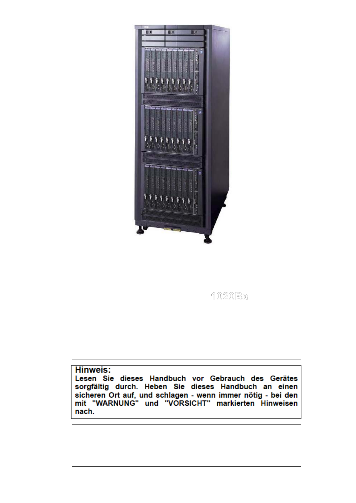
XPRESS5800/1020Ba
User’s Guide
Page 2

Page 3
855-900470-002-A
456-01707-001
NEC Express Server
NEC Express5800 Series
NEC Express5800/
User’ s Guide
NOTE:
Read this manual carefully before using the unit. Keep this manual
nearby as a handy reference and refer to the “CAUTION” and
“WARNING” statements whenever necessary.
NOTE:
Lisez attentivement ce manuel avant d’utiliser le matériel. Conservez
ce manuel à portée de main, pour une aide pratique et référez-vous
aux rubriques « PRUDENCE » et « AVERTISSEMENT » chaque fois
que nécessaire.
2nd Edition Jul. 2005
Page 4

Proprietary Notice and Liability Disclaimer
The information disclosed in this document, including all designs and related materials, is the valuable
property of NEC Solutions (America), Inc. and/or its licensors. NEC Solutions (America), Inc. and/or its
licensors, as appropriate, reserve all patent, copyright and other proprietary rights to this document,
including all design, manufacturing, reproduction, use, and sales rights thereto, except to the extent said
rights are expressly granted to others.
The NEC Solutions (America), Inc. product(s) discussed in this document are warranted in accordance
with the terms of the Warranty Statement accompanying each product. However, actual performance of
each product is dependent upon factors such as syste m configuration, customer data, and operator control.
Since implementation by customers of each product may vary, the suitability of specific product
configurations and applications must be determined by the customer and is not warranted by NEC
Solutions (America), Inc.
To allow for design and specification improvements, the information in this document is subje ct to change
at any time, without notice. Reproduction of this document or portions thereof without prior written app roval
of NEC Solutions (America), Inc. is prohibited.
Trademarks
ESMPRO and CLUSTERPRO are trademarks of NEC Corporation. EXPRESSBUILDER is a trademark of NEC Corporation.
Microsoft, Windows, Windows NT, and MS-DOS are either registered trademarks or trademarks of Microsoft Corporation in the
United States and/or other countries. Intel is a trademark of Intel Corporation. Itanium is a trademark of Intel Corporation. AT- is a
trademark of International Business Machines Corporation in the United States and/or other countries. Datalight is a trademark of
Datalight, Inc. ROM-DOS is trademark of Datalight, Inc. DLT and DLTtape are trademarks of Quantum Corporation. Adobe and
Adobe logo, and Acrobat are trademarks of Adobe Systems Incorporated. Red Hat is a registered trademark of Red Hat, Inc. Linux is
a registered trademark of Linux Torvalds. Topspin is a trademark of Topspin Communications. InfiniBand is a registered trademark of
InfiniBand Trade Organization. DVC Technology and the Interface Subsystem is a registered trademark of Avocent. Other product
and company names mentioned herein may be the trademarks or registered trademarks of their respective owners.
Limited Edition is the abbreviated name of Microsoft ®Windows ®Advanced Server, Limited Edition. Windows XP is the abbreviated
name of Microsoft ®Windows ®XP Home Edition operating system or Microsoft Windows XP Professional operating system.
Windows 2000 is the abbreviated name of Microsoft ®Windows ®2000 Server operating system, Microsoft ®Windows ®2000
Advanced Server operating system, or Microsoft ®Windows ®2000 Professional operating system. Windows NT is the abbreviated
name of Microsoft ®Windows NT ®Server network operating system version 3.51/4.0 or Microsoft ®Windows NT ®Workstation
operating system version 3.51/4.0. Windows Me is the abbreviated name of Microsoft ®Windows ®Millennium Edition Operating
System. Windows 98 is the abbreviated name of Microsoft ®Windows ®98 operating system. Windows 95 is the abbreviated name of
Microsoft ®Windows ®95 operating system.
Express5800/1020Ba employs Linux for KVMOS. Refer to the license put in “KVMOS” directory of EXPRESSBUILDER for copyright
and property.
NEC Express5800/1020Ba Itanium® 2 Blade server system employs "Avocent DVC Technology" for integrative system console.
(U.S. Patent Numbers: 5,721,842, 5,732,212, 5,884,096, 5,937,176, 6,112,264, 6,633,905, 6,681,250, 6,701,380 and other patents
pending. Taiwanese Patent Number: 173784. European Patent Number: 0 740 811)
Names used in sample applications are all fictitious, having no relations to existing product, organization, and individual name.
i
Page 5
Disposing of your used NEC product
In the European Union
EU-wide legislation as implemented in each Member State
requires that used electrical and electronic products carrying
the mark (left) must be disposed of separately from normal
household waste. When disposing of used NEC products, you
should comply with applicable legislation or such terms which
may have been agreed between NEC and your company
regarding used products. The mark on the electrical and
electronic products only applies to the current European Union
Member States.
Outside the European Union
If you wish to dispose of used electrical and electronic products
outside the European Union, please contact your local authority
and ask for the correct method of disposal.
Entsorgung Ihres gebrauchten NEC Produktes
In der Europäischen Union
EU – weit verlangt das in jedem Mitgliedsland geltende Recht,
dass elektrische und elektronische Produkte, welche das
nebenstehende Zeichen (links) tragen, getrennt vom normalen
Hausabfall entsorgt werden müssen. Wenn Sie gebrauchte
NEC Produkte entsorgen, halten Sie sich an das geltende
Recht oder die Bedingungen, welche zwischen Ihrer Firma und
NEC bezüglich der gebrauchten Produkte vereinbart wurden.
Das Zeichen auf den elektrischen und elektronischen
Produkten gilt nur für die Mitgliedsländer der Europäischen
Union.
Außerhalb der Europäischen Union
Wenn Sie gebrauchte elektrische und elektronische Produkte
außerhalb der Europäischen Union entsorgen möchten, dann
kontaktieren Sie bitte Ihre lokalen Behörden und erkundigen
Sie sich nach der korrekten Art der Entsorgung.
Que faire de votre produit NEC usagé
À l'intérieur de l'Union européenne
La législation en vigueur au niveau de l'Union européenne
(UE), telle que mise en œuvre dans chaque État membre,
stipule que les produits électriques et électroniques usagés
portant le signe représenté à gauche doivent être mis au rebut
séparément des déchets ménagers normaux. Ainsi, lorsque
vous voudrez jeter vos produits NEC usagés, vous devrez
vous conformer à la législation ad hoc ou aux éventuelles
modalités convenues entre NEC et votre entreprise concernant
lesdits produits. Ce signe sur les produits électriques et
électroniques ne s'applique qu'aux États membres actuels de
l'UE.
À l'extérieur de l'Union européenne
Si vous souhaitez vous débarrasser de produits électriques et
électroniques usagés en dehors de l'Union européenne,
contactez l'autorité locale compétente pour connaître la
marche à suivre.
ii
Page 6

FCC COMPLIANCE
Federal communication commission radio frequency interference statement
NOTE: This equipment has been tested and found to comply with the limits for a
Class A digital device, pursuant to Part 15 of the FCC Rules. These limits are
designed to provide reasonable protection against harmful interference when the
equipment is operated in a commercial environment. This equipment generates,
uses, and can radiate radio frequency energy and, if not installed and used in
accordance with the instruction manual, may cause harmful interference to radio
communications. Operation of this equipment in a residential area is likely to
cause harmful interference in which case the user will be required to correct the
interference at his or her own expense.
EN COMPLIANCE
Warning
This is Class A product. In a domestic environment this product may cause radio
interference in which case the user may be required to take adequate measures.
iii
Page 7
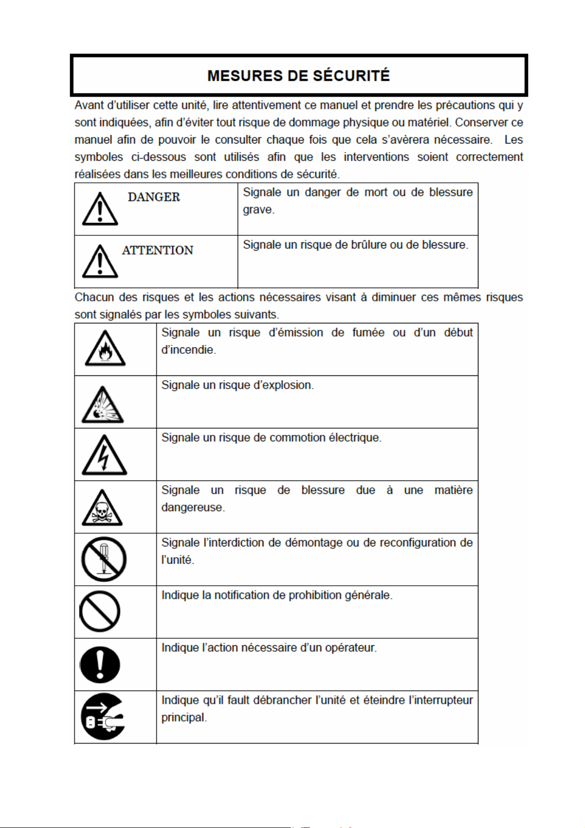
SAFETY PRECAUTIONS
Before using this unit, read this manual carefully and keep these instructions in order
to use this unit safely and correctly and to avoid injury and damage to persons or
property. Keep this manual handy for easy reference.
The following symbols are used in this manual to help you easily understand how to
operate the unit safely and correctly.
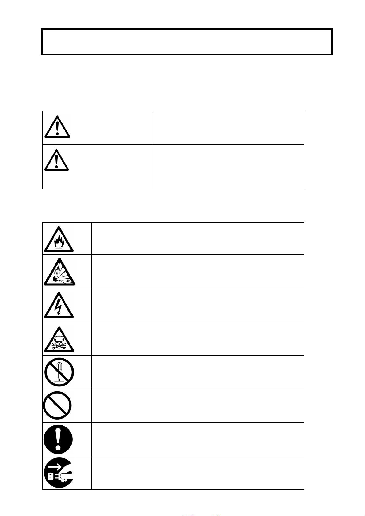
Indicates a potentially hazardous situation
which, if not avoided, could result in death or
WARNING
CAUTION
serious injury.
Indicates a potentially hazardous situation
which, if not avoided, may result in minor or
moderate injury. It may also be used to alert
against unsafe practices.
Risks and necessary actions to reduce risks are indicated individually by the following
symbols.
Indicates smoke or fire hazard.
Indicates risk of explosion.
Indicates risk of electric shock.
Indicates potential injury due to harmful material.
Indicates disassembling or reconfiguring the unit is prohibited.
Indicates general action is prohibited.
Indicates a required action for the operator.
Indicates instructions to pull power plug from outlet and to turn
OFF main circuit breaker.
iv
Page 8
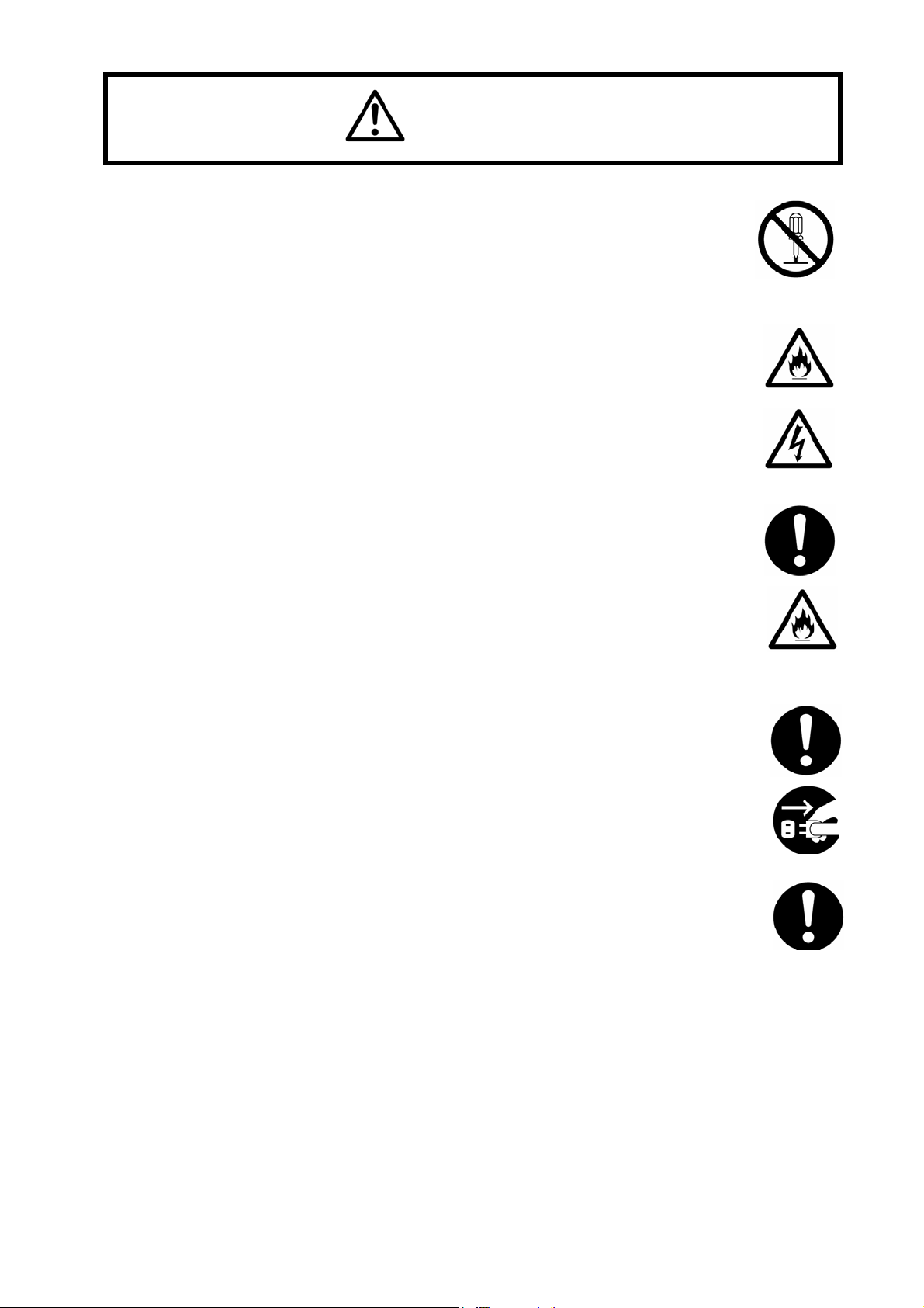
WARNING
DO NOT TRY TO ACCESS INSIDE THE UNIT.
Only an authorized NEC service representative is allowed to open the door.
Never disassemble, repair or reconfigure the unit yourself. While the door is opened by an
authorized NEC service representative for maintenance, do not touch nor access the
inside of the unit, otherwise you may suffer an electrical shock or become injured.
DO NOT PUT FOREIGN SUBSTANCES INSIDE THE UNIT.
Do not insert foreign material, such as wire or other metal objects through a ventilation
opening or any other openings.
Foreign materials may cause a fire to break out or cause an electrical shock.
EXCHANGING AND DISPOSING THE LEAD-ACID BATTERY.
A Lead-Acid battery is used in this unit.
The life period of a Lead-Acid battery is limited. Fire or trouble in this unit may result from
using a dead Lead-Acid battery. Replacing the lead-acid battery should be done
periodically, depending on usage, by contacting an authorized NEC service
representative.
Proper disposal of the lead-acid battery should only be done by an authorized NEC
service representative.
ACTION TO BE TAKEN DURING UNIT MALFUNCTION
In case of a malfunction, turn off the circuit breaker immediately and contact an
authorized NEC service representative.
ACTION TO BE TAKEN IN AN EMERGENCY SITUATION
The Emergency Power Off (EPO) switch can be used in an emergency situation when
there is danger present and the main power needs to be disconnected immediately.
Because data will be lost or damaged when this occurs, employees should be
forewarned. For additional details, please contact an authorized NEC service
representative.
v
Page 9
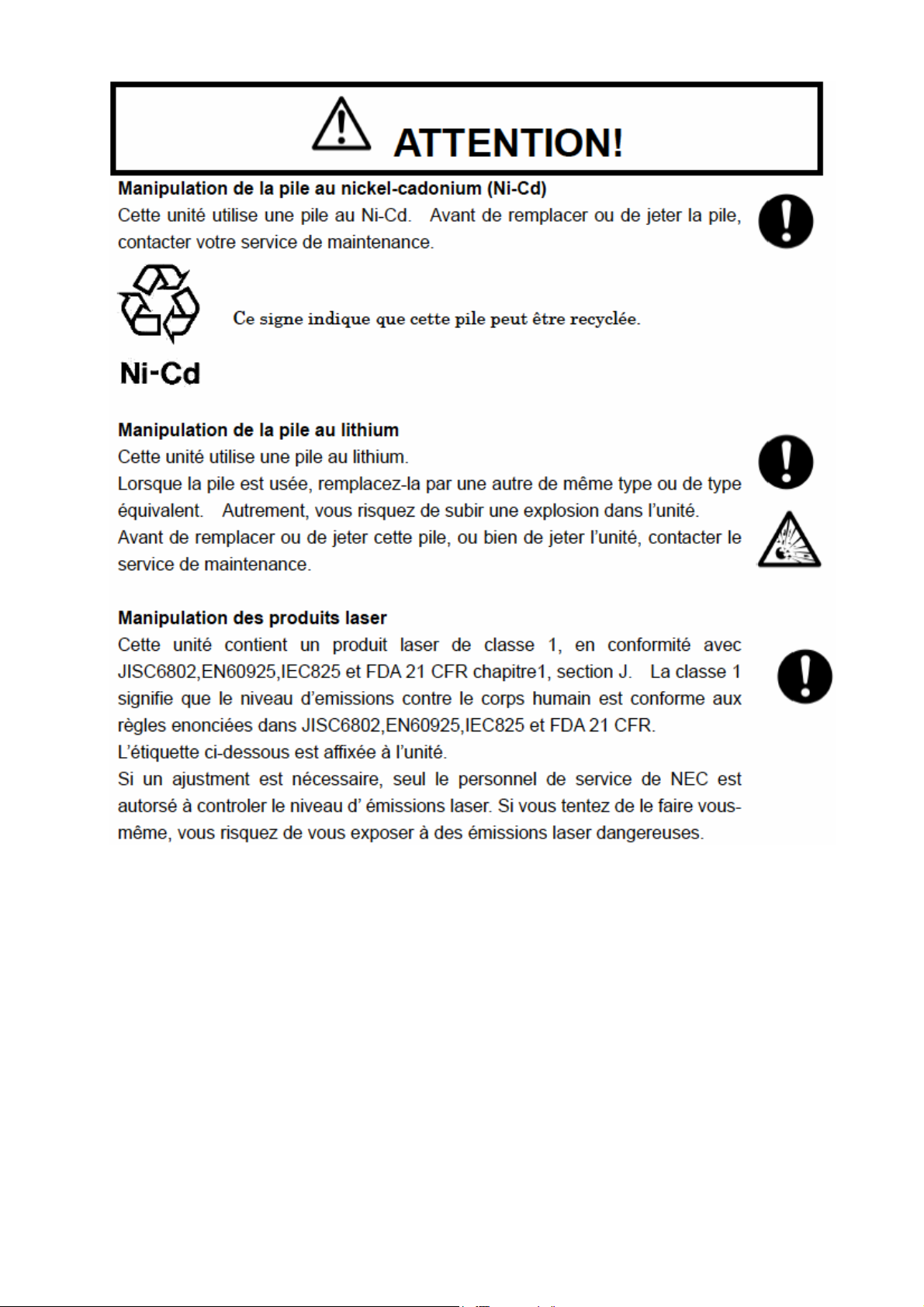
CAUTION
HANDLING THE Ni-Cd BATTERY
A Ni-Cd battery is used in this unit.
Contact an authorized NEC service representative replacing or disposing of the Ni-Cd
battery or the unit.
This marking means the Ni-Cd battery is recyclable. This battery is recyclable.
HANDLING THE LITHIUM BATTERY
A lithium battery is used in this unit. Incorrect replacement of the lithium battery could
result in an explosion. The same type or an equivalent type of battery is recommended
by the manufacturer. Contact an NEC trained service representative before replacing or
disposing of the lithium battery.
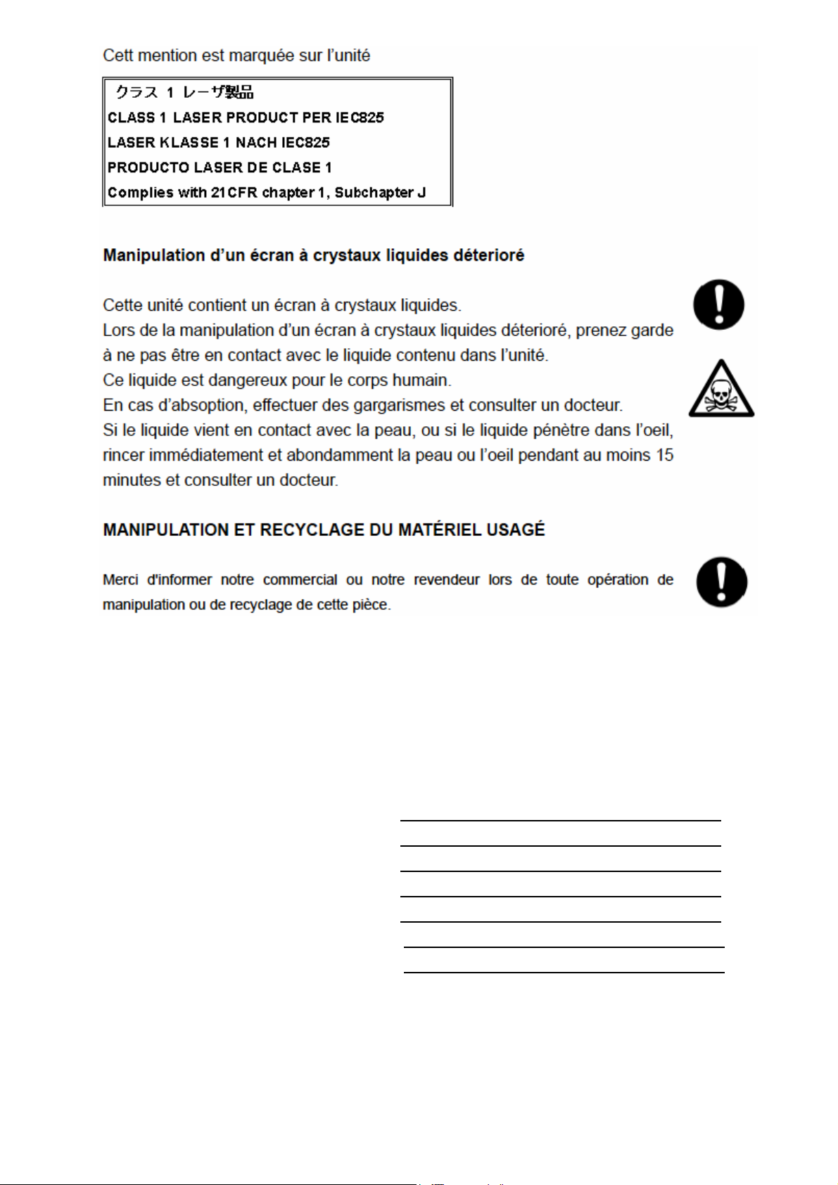
HANDLING LASER PRODUCTS
A Class 1 laser product that complies with JISC6802, EN60825, IEC825 and FDA 21CFR chapter1,
subchapter J is used in this unit.
NOTE: Class 1 laser product is regarded safety emission label for the body, stated in JISC6802,
EN60825, IEC825 and FDA 21CFR.
If there is an adjustment which can affect the laser emission power level, do not touch nor adjust
without an authorized NEC service representative’s permission, otherwise harmful laser could be
emitted and you would be exposed to it.
This marking is put on this unit.
vi
Page 10

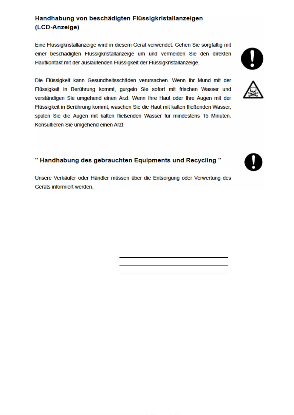
HANDLING A DAMAGED LIQUID CRYSTAL DISPLAY
A liquid crystal display is used in this unit.
When handling a damaged liquid crystal display, be careful and avoid exposure of the
liquid on the inside of the liquid crystal display.
The liquid can cause bodily harm. In the event the liquid is ingested, gargle at once and
consult a doctor immediately.
If the liquid should come in contact with skin, or get into eyes, wash the skin with cool
running water, or flush eyes with cool running water for at least 15 minutes and consult a
doctor.
HANDLING DISPOSAL OR RECYCLING OF EQUIPMENT
Please let an NEC sales representative or dealer know when discarding or recycling this
unit.
Note to Customer
Please print from the cover page to page xviii of this manual, and ask this product's dealer to fill in the
blanks listed below.
CONTACT INFORMATION
Contact for :
Contact Person :
TEL :
FAX :
Address :
vii
Page 11
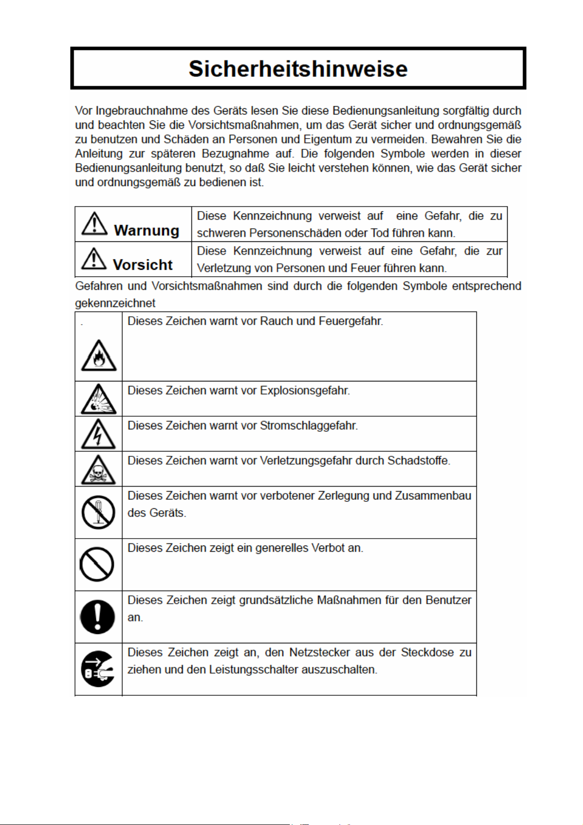
Sicherheitshinweise
viii
Page 12
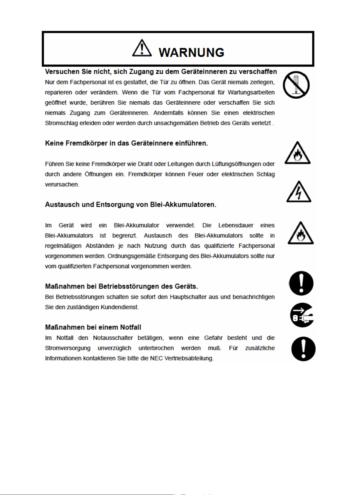
WARNUNG
ix
Page 13
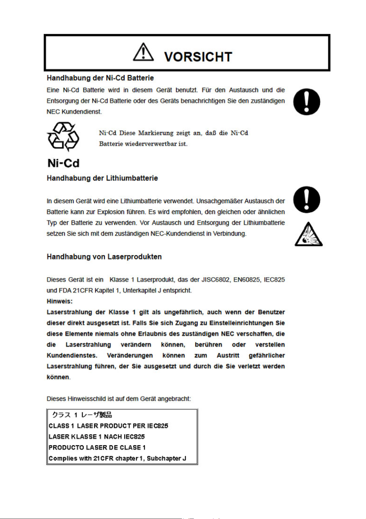
VORSICHT
x
Page 14
Kundeninformation
Bitte wenden Sie sich an den Produkthändler um untenstehende Informationen zu vervollständigen.
Kontaktinformation
Informationen unter :
Ansprechpartner :
Telefon :
Fax :
Adresse :
xi
Page 15
MESURES DE SÉCURITÉ
xii
Page 16

DANGER!
xiii
Page 17
ATTENTION!
xiv
Page 18
NOTE TO CUSTOMER
Information au client : Demander au fournisseur de remplir le questionnaire ci-dessous.
FICHE DE RENSEIGNEMENT
Nom de la société / service :
Nom du contact :
Numéro de téléphone :
Numéro de télécopie :
Adresse :
xv
Page 19
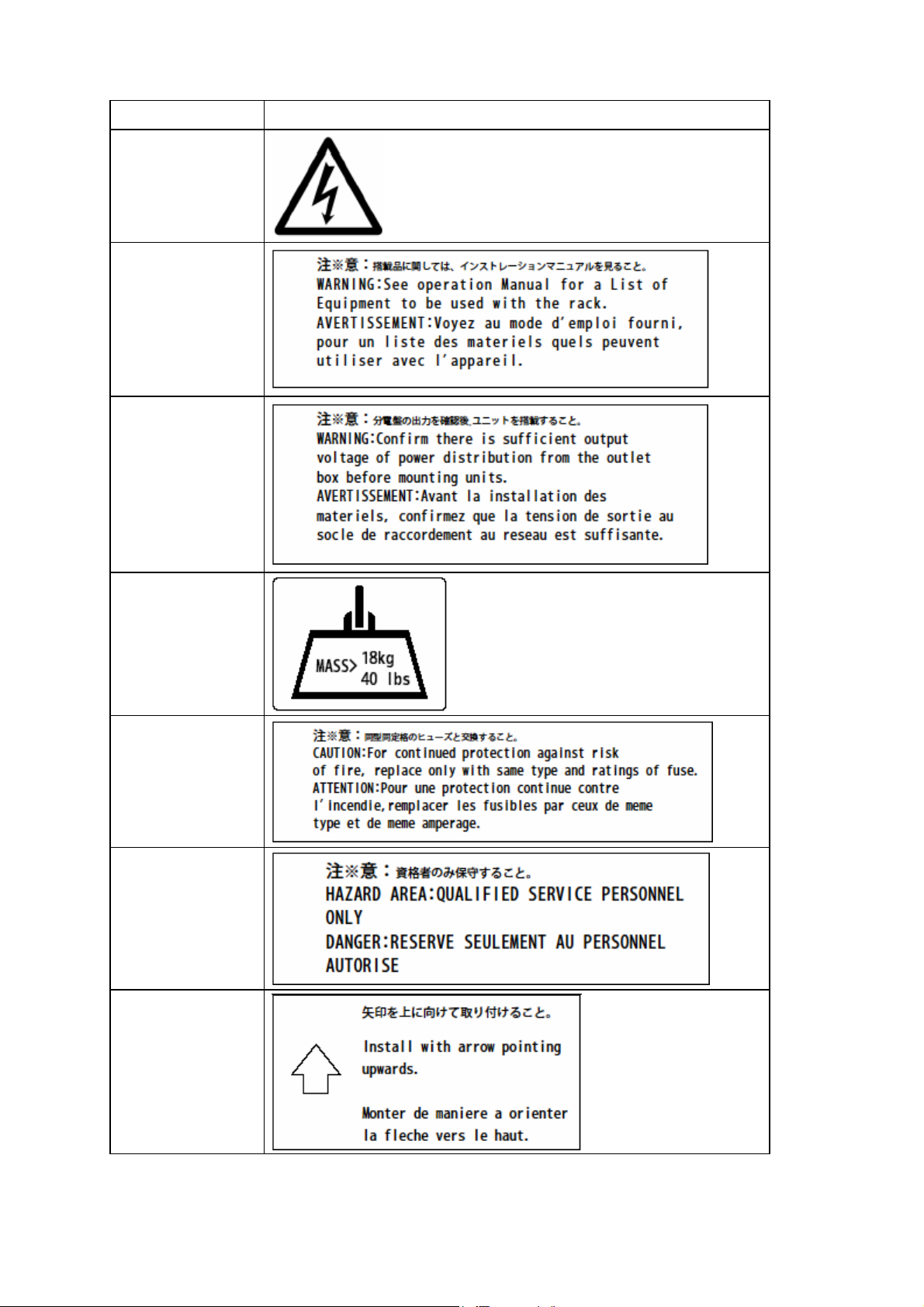
Marking Labels
133–300656–GRP MARKINGS
001
031
033
103
140
150
163
xvi
Page 20
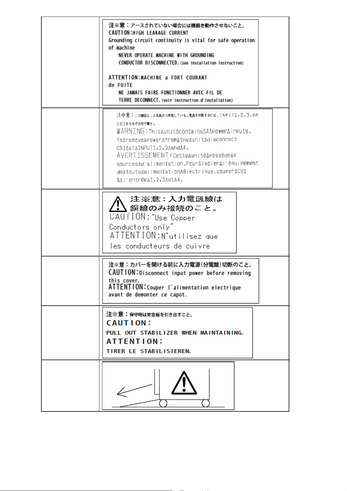
165
211
217
243
416
417
xvii
Page 21
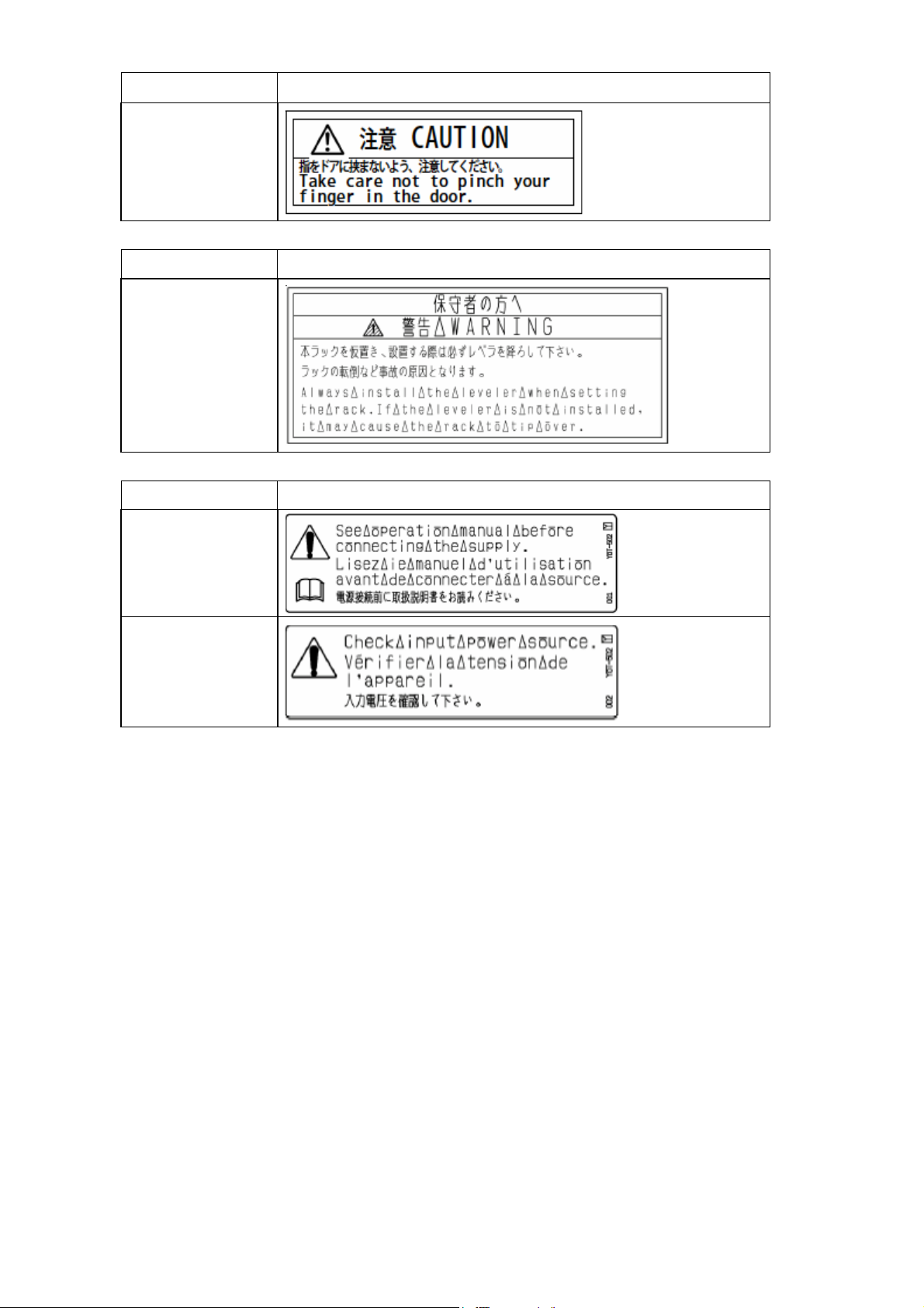
133-314121-GRP MARKINGS
055
243-304367-GRP MARKINGS
001
243-306629-GRP MARKINGS
001
002
xviii
Page 22

Preface
This document describes how to use the hardware of the Express5800/1020Ba. Please read all other
related manuals to fully utilize the functionality of the Express5800/1020Ba. Contact your NEC sales
representative for installation and adding components to the Express5800/1020Ba because these
jobs require qualified engineers.
R2.0 Jul, 2005
Notes
This manual might be revised without notification in the future.
NOTE:
Ce manuel pourra être révisé sans aucun avertissement préalable dans un
futur proche.
xix
Page 23

Revision History
Revision Date Description
R1.0 Jan, 2005 First Revision
R2.0 Jul, 2005 - RHEL 3.0 supported.
- Video Viewer renewed.
- How to set report notification destination address
- How to update initrd image (WS 3)
xx
Page 24

Table of Contents
SAFETY PRECAUTIONS ..................................................................................................................iv
WARNING...........................................................................................................................................v
CAUTION...........................................................................................................................................vi
Sicherheitshinweise...................................................................................................................... viii
WARNUNG.........................................................................................................................................ix
VORSICHT..........................................................................................................................................x
MESURES DE SÉCURITÉ............................................................................................................... xii
DANGER!........................................................................................................................................ xiii
ATTENTION!....................................................................................................................................xiv
Marking Labels ...............................................................................................................................xvi
Preface ............................................................................................................................................xix
Revision History..............................................................................................................................xx
Section 1
1.1 Components and Specification...................................................................................1-2
1.2 Expansion....................................................................................................................1-4
1.3 Optional Unit / Device / Part........................................................................................ 1-7
Section 2
2.1 Component Name and Functionality.......................................................................... 2-1
System Overview ......................................................................................................1-1
1.2.1 Processor................................................................................................................... 1-5
1.2.2 Memory ...................................................................................................................... 1-5
1.2.3 HDD ............................................................................................................................ 1-6
1.2.4 CPU Blade .................................................................................................................. 1-6
Components and Functionality................................................................................ 2-1
2.1.1 Cabinet....................................................................................................................... 2-1
2.1.2 Blade Chassis............................................................................................................ 2-1
2.1.3 CPU Blade .................................................................................................................. 2-2
2.1.4 CMM Blade................................................................................................................. 2-6
2.1.5 DVD-ROM Drive......................................................................................................... 2-9
2.1.6 PowerBay................................................................................................................. 2-10
2.1.7 Emergency Power Off............................................................................................. 2-10
2.2 Console......................................................................................................................2-11
2.2.1 Physical Console Configuration.............................................................................2-11
2.2.2 Suggested Console Spec....................................................................................... 2-12
2.2.3 CMM Web Console.................................................................................................. 2-13
2.2.4 Local KVM Console................................................................................................. 2-25
2.2.5 Host Telnet Console................................................................................................ 2-39
2.2.6 Video Viewer............................................................................................................ 2-40
2.2.7 Virtual Media............................................................................................................ 2-63
xxi
Page 25

Section 3
3.1 System View.................................................................................................................3-1
3.2 Starting Up the System................................................................................................3-2
3.3 Initial Settings.............................................................................................................. 3-3
3.4 Booting the OS ............................................................................................................3-4
3.5 System Configuration -- SETUP -- ............................................................................ 3-10
System Operation .....................................................................................................3-1
3.2.1 Power ON/OFF sequence ......................................................................................... 3-2
3.3.1 Set IP Address........................................................................................................... 3-3
3.4.1 OS Boot from EFI Boot Manager ............................................................................. 3-4
3.4.2 EFI Boot Manager...................................................................................................... 3-4
3.4.3 EFI Shell [Built-in]..................................................................................................... 3-4
3.4.4 Backup BIOS Setup / EFI Setting Information........................................................ 3-8
3.5.1 Starting Setup.......................................................................................................... 3-10
3.5.2 Screen Description ..................................................................................................3-11
3.5.3 Menu Tree................................................................................................................ 3-12
3.5.4 Reset CMOS/NVRAM Password............................................................................. 3-23
Section 4
4.1 Overview........................................................................................................................ 4-1
4.2 Management PC Software...........................................................................................4-2
4.3 CPU Blade Software ....................................................................................................4-4
Section 5
5.1 Power ...........................................................................................................................5-1
5.2 OS.................................................................................................................................5-1
5.3 IO..................................................................................................................................5-1
5.4 Peripheral.....................................................................................................................5-1
Software..................................................................................................................... 4-1
4.2.1 Management PC Requirement ................................................................................. 4-2
4.2.2 DeploymentManager................................................................................................. 4-2
4.2.3 ESMPRO/ServerManager.......................................................................................... 4-3
4.2.4 InfiniBand Management software and others......................................................... 4-3
4.3.1 DPM Client Service ................................................................................................... 4-4
4.3.2 OS (RedHat Enterprise Linux).................................................................................. 4-4
4.3.3 ESMPRO/ServerAgent.............................................................................................. 4-9
Troubleshooting........................................................................................................ 5-1
Section 6 Handling Precautions ............................................................................................... 6-1
6.1 Transportation .............................................................................................................6-1
6.2 DVD-ROM/CD-ROM......................................................................................................6-1
6.3 Cleaning.......................................................................................................................6-1
6.4 Installing Precautions..................................................................................................6-1
xxii
Page 26

<Intentionally Left Blank>
xxiii
Page 27
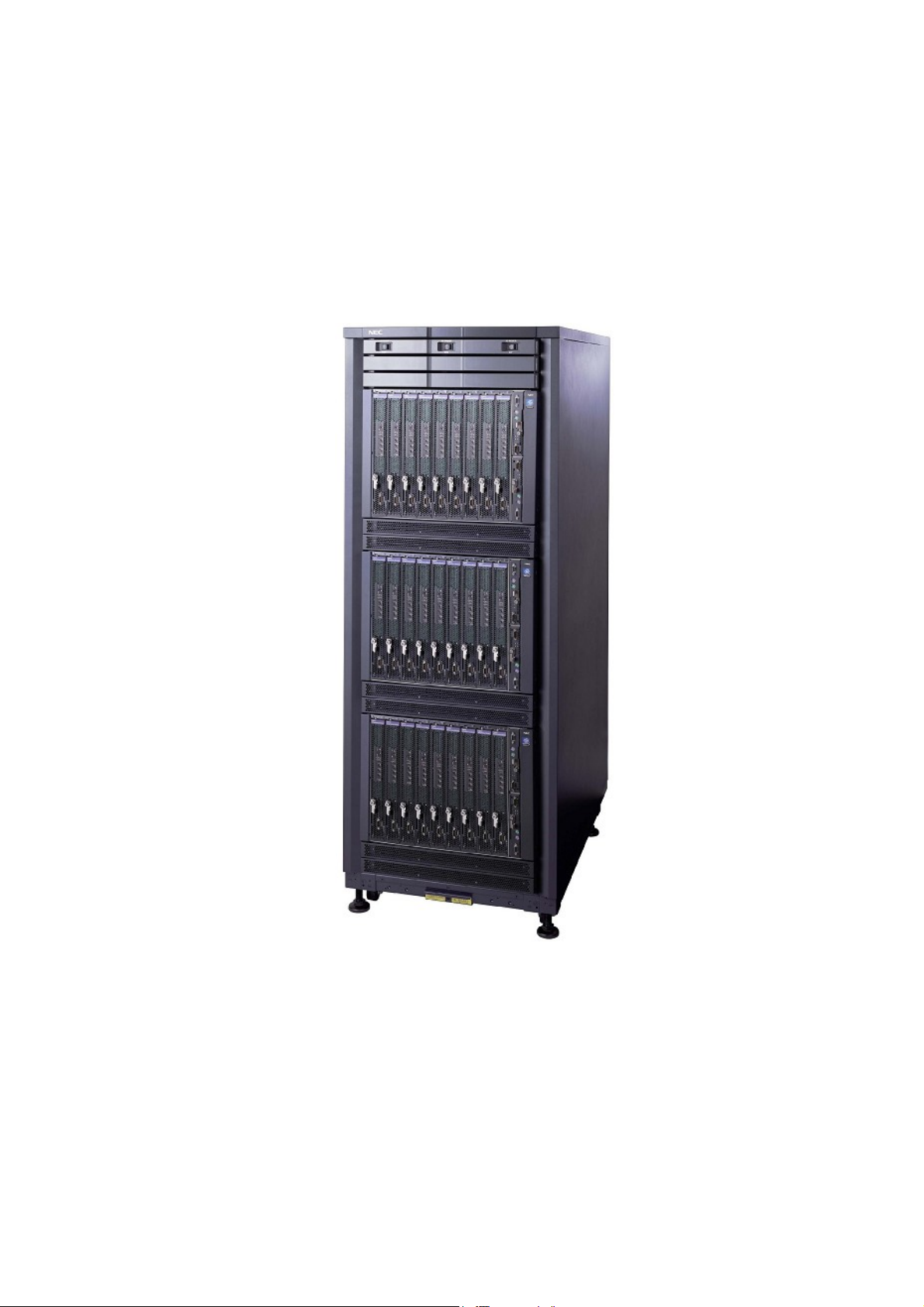
Section 1 System Overview
The Express5800/1020Ba Intel® Itanium® 2 Blade server provides the following features:
- High performance
- High scalability
- High reliability
- High density
- Red Hat Linux ready
- Efficient management environment
- Excellent program development environment
Figure 1.1-1 Express5800/1020Ba
1-1
Page 28

1.1 Components and Specification
1. CPU Blade
- One or two Intel
®
Itanium® 2 processors
- Minimum of 2GB (4 x 512MB DIMM) to maximum of 24GB (12 x 2GB DIMM) main memory
- One or two 73GB HDDs
- One PCI-X (64bit/133MHz) slot
- Dual 1000Base-T Ethernet ports
- One Serial (RS-232C) interface
2. Chassis Management Module (CMM)
- Dual 10/100Base-T Ethernet ports
- One Serial (RS232C) interface
- One Keyboard / Mouse (PS/2) interface
- One VGA (analog) interface
3. Blade Chassis
- Up to 9 CPU Blades
- One CMM Blade
- One DVD-ROM Drive
- Two USB 1.1 ports
1-2
Page 29

Table 1.1-1 shows the CPU Blade and the Blade Chassis specifications.
Table 1.1-1 Express5800/1020Ba CPU Blade and Blade Chassis Specifications
Name CPU Blade
®
Itanium® 2 - DP
CPU
Processor
Intel
Processor
Clock (GHz) 1.6GHz 1.6GHz 1.5GHz
®
Intel
Itanium® 2 Processor
L3 Cache (MB) 3MB 9MB 6MB 4MB
Maximum Number of CPU 2
Maximum Size of Main Memory 24GB
Internal Storage Max. Internal HDD 73GB×2
Expansion Slot PCI-X 1
Interface 1000BASE-T×2
Power / CPU blade 557W 557W 541W
OS RedHat Enterprise Linux
Name Rack Mount Chassis
CPU Blade 9 Maximum
Number
Management Module 1
Internal Device DVD-ROM
Voltage AC 200V (Single Phase)
Power
Conditions
Physical
Dimensions
Environment
Conditions
Frequency 50/60Hz
Heat
Chassis Type
(9 CPU Blade + 1 CMM Blade with N+1 power configuration)
<1020Ba Chassis (8U) + Power Module (2U) >
18,372kJ/h
Rack mountable
Width 483mm
Depth 785mm
Height 445mm
Weight
Temperature
Humidity
(9 CPU Blade + 1 CMM Blade with N+1 power configuration)
Operating +5 - +35 degree C
Not Operating +5 - +45 degree C
Operating 20-80%RH (No Condensation)
Not Operating 8-80%RH (No Condensation)
Up to 177.5kg
1-3
Page 30
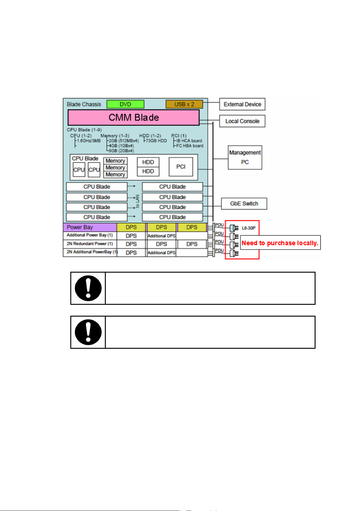
1.2 Expansion
This section describes the expandability of the Express5800/1020Ba and its possible configurations.
Figure 1.2-1 shows one Express5800/1020Ba possible configuration.
Figure 1.2-1 Express5800/1020Ba System Configuration
Contact qualified personnel, such as an authorized NEC service
representative, for adding or removing server components.
Do not add components that are not qualified by NEC.
1-4
Page 31

1.2.1 Processor
One or two Intel
®
Itanium® 2 processor must be installed in a CPU Blade. (The same type of
processor must be installed in a CPU Blade.)
1.2.2 Memory
A CPU Blade has 12 DIMM slots. Memory must be installed in groups of four DIMMs of the same
capacity. A minimum of 2GB (four 512MB DIMMs) must be installed in a CPU blade and up to 24GB
(twelve 2GB DIMMs) can be installed in a CPU blade.
Part Number
Part Name Description
NV4401-E151/H151 Memory (2GB) 4 x 512MB DIMM
NV4401-E152/H152 Memory (4GB) 4 x 1GB DIMM
NV4401-E153/H153 Memory (8GB) 4 x 2GB DIMM
Figure 1.2-2 shows DIMM locations in a CPU Blade.
CPU Blade
A3
A4
C4
B4
C3
B3
A1
A2
C2
B2
C1
B1
Front Rear
Figure 1.2-2 DIMM locations
Table 1.2-1 shows DIMM installation rules. (Please install groups of four DIMMs with order Ax Æ Bx Æ
Cx.)
Table 1.2-1 DIMM installation Rules
Installation Order DIMM location
1) A1, A2, A3, A4
2) B1, B2, B3, B4
3) C1, C2, C3, C4
1-5
Page 32

1.2.3 HDD
One or two HDDs must be installed in a CPU blade.
Part Number
Part Name Description
NV4401-E160/H160 HDD (73GB) 73GB HDD
1.2.4 CPU Blade
At least one and up to nine CPU blade can be installed in a Blade Chassis.
Part Number
Part Name Description NV4401-E001/H001 CPU Blade No processor / No memory / No HDD
When adding CPU Blades, additional PowerBay and/or DPS units may be needed depending on the
number of CPU blades.
2N Redundant Power Module also needs additional PowerBay and/or DPS units depending on the
number of CPU blades.
Part Number
Part Number Description
NV4403-E001 Additional PowerBay 1 x PowerBay / 1 x DPS
NV4403-E002 2N Redundant Power Module 1 x PowerBay / 3 x DPS
NV4403-H002 2N Redundant Power Module 2 x PowerBay / 5 x DPS
NV4403-E003 2N Additional PowerBay 1 x PowerBay / 1 x DPS
NV4403-E101 Additional DPS 1 x DPS
The Blade Chassis is bundled with 1 x PowerBay and 3 x DPS. For a 2N redundant power
configuration, a 2N Redundancy Power Module option is required. The additional PowerBay and the 2N
additional PowerBay items are each bundled with 1 x DPS, and an additional DPS can be added.
Note: the 2N redundant power configuration is longer available.
The table below shows the necessary options required per CPU blades.
Table 1.2-2 Number of PowerBay and DPS
Number of
CPU Blade
1 - 4 1 3 2
5 - 7 2
8 - 9 2
Default Power Configuration (N+1 ) 2N Redundant Power Configuration
Number of PowerBay Number of DPS Number of PowerBay Number of DPS
6
8
*1
)
10
NV4403-E101 ×2
*1
)
NV4403-E001 ×1
NV4403-E001 ×1
NV4403-E101 ×1
NV4403-E002 ×1
NV4403-H002 x 1
4 4
NV4403-E001 ×1
NV4403-E002 ×1
(NV4403-H002 ×1
5
4
NV4403-E001 ×1
NV4403-E002 ×1
(NV4403-H002 ×1
Note: Part Number is the required option for a configuration.
*1. NV4403-H002 can cover nine blades configuration.
1-6
Page 33

1.3 Optional Unit / Device / Part
The table shows the Express5800/1020Ba optional unit / device / part.
<Express5800/1020Ba Base Module>
Part Number Part Name Description
1 x Rack Mountable Chassis, 1 x CMM Blade, 1 x
NV4400-E001/H001 Blade Chassis
NV4401-E001/H001 CPU Blade CPU Blade – No CPU / No Memory / No HDD
NV4401-E105/H105 CPU (1.6GHz, 6MB)
NV4401-E106/H106 CPU (1.6GHz, 9MB)
NV4401-E107/H107 CPU (1.5GHz, 4MB)
NV4401-E108/H108 CPU (1.6GHz, 3MB)
NV4401-E151/H151 Memory (2GB) 2GB Memory (4 x DIMM512MB)
NV4401-E152/H152 Memory (4GB) 4GB Memory (4 x DIMM1GB)
NV4401-E153/H153 Memory (8GB) 8GB Memory (4 x DIMM2GB)
NV4401-E160/H160 73GB HDD 73GB HDD + HDD Carrier
NV4403-E001 Additional PowerBay
NV4403-E101 Additional DPS
PowerBay with 3 DPS, 1 x DVD-ROM
No CPU Blade is included.
CPU (Itanium2, 1.6GHz,6MB) 1 x (CPU with Heatsink
+ PowerPod)
CPU (Itanium2, 1.6GHz,9MB) 1 x (CPU with Heatsink
+ PowerPod)
CPU (Itanium2, 1.5GHz,4MB) 1 x (CPU with Heatsink
+ PowerPod)
CPU (Itanium2 DP, 1.6GHz,3MB) 1 x (CPU with
Heatsink + PowerPod) (Fanwood )
Power Supply Module 1 x PowerBay with 1 PDU and 1
DPS. Necessary for the configuration with more than 5
CPU Blades.
1 x DPS. Necessary option for the configuration with
more than 8 CPU Blades
(Add to NV4403-001 Additional PowerBay or NV-4403003 2N Additional PowerBay)
<PCI Card>
Part Number Part Name Description
NV2010A-A001/E001 FC HBA card 2Gbps FC HBA
NV4470-001/E001 IB HCA card Infiniband HCA
< Infiniband Device >
N code Name Description
NV4471-E001 IB Switch TS-90 12port(4X) IB switch + 1 Gateway slot
NV4471-E002 IB Switch TS-360 12port(4X) IB switch + 12 Gateway slots
NV4471-E003 IB Switch TS-360 FT 24port(4X) IB switch + 12 Gateway slots
NV4471-E004 IB Switch TS-120 24port(4X) IB switch
NV4472-E001 IB FC Gateway IB to FC (2Gbps) Gateway 2port
NV4474-E001 IB 4X Switch Module 12port 4X Switch Module 12port for NV4471-002
NV4474-E002 Controller Module Controller Module for NV4471-002
NV4474-E003 Power Supply Power Supply for NV4471-002
<Storage Device (NEC Storage series) >
Product Name Description
Disk Array S1300
Disk Array S2300
Disk Array S1400
Disk Array S2400
Disk Array S2800
Note: Please contact an NEC sales representative for more information.
1-7
Page 34

Intentionally Left Blank
1-8F
Page 35

Section 2 Components and Functionality
This section describes information necessary to operate the Express 5800/1020Ba.
2.1 Component Name and Functionality
2.1.1 Cabinet
The Express5800/1020Ba must be mounted into a cabinet or rack.
Contact qualified personnel, such as an authorized NEC service representative,
for moving the cabinet.
2.1.2 Blade Chassis
9 x CPU Blades, 1 x CMM Blade, and 1 x DVD-ROM can be installed in a Blade Chassis.
Figure 2.1-1 shows the location of each component.
Figure 2.1-1 Components Location
2-1
Page 36

2.1.3 CPU Blade
The CPU Blade has an Intel chipset and management controller and can support up to two
®
Itanium® 2 processors, up to twelve DIMMs, and up to two HDDs. The CPU Blade has one
Intel
133MHz PCI-X slot, dual 10/100/1000 Base-T Ethernet ports and one serial interface. Up to nine
CPU Blades can be installed in one Blade Chassis.
Figure 2.1-2 CPU Blade
The Serial interface is for maintenance purpose only. Do not connect a serial
cable during normal operation.
2-2
Page 37

2.1.3.1 CPU Blade Front Panel
Figure 2.1-3 shows the CPU Blade front panel.
Figure 2.1-3 CPU Blade Front Panel
2-3
Page 38

Table 2.1-1 and Table 2.1-2 show the functionalities of the CPU Blade front panel LEDs and
switches.
Table 2.1-1
LED Color*1 Status Description
ON DC48V ON*2
Power Green
Green*3
Status
Amber
ID Blue
KVM Green
Media Green
HDD Green
GbE ACT port A Green
GbE LINK port A Green
GbE ACT port B Green
GbE LINK port B Green
*1 Amber LED has higher priority than Green LED.
*2 Power LED is temporarily lights right after AC power on.
*3 Only available when IPMI driver is installed.
BLINK(Fast) Cooling before DC48V OFF
BLINK(Slow) Stand-By with BMCFW ready
OFF Not Stand-By or BMCFW not operating normally.
OFF OS not running
ON OS running
BLINK OS running with Processor / DIMM degrade
OFF Normal operation
ON Uncorrectable Error
OFF Normal Operation
ON ID Switch is pressed
BLINK Button control from CMM Web or turned on by SMS
OFF Not using KVM switch
ON Using KVM
BLINK Requesting KVM
OFF Not using Media devices
ON Using Media
BLINK Requesting Media
OFF Not Accessing internal HDD
ON Accessing internal HDD
OFF Not sending or receiving packets on port A
ON Sending or receiving packets on port A
OFF No link on port A
ON Link up on port A
OFF Not sending or receiving packets on port B
ON Sending or receiving packets on port B
OFF No link on port B
ON Link up on port B
CPU Blade LED
*2
2-4
Page 39

Table 2.1-2 CPU Blade Switch
Switch Function
Power Switch
Reset Switch
Dump Switch
ID Switch
Media Switch
KVM Switch
Controls Power On/Off of the CPU Blade.
Pressing for more than 4 seconds will force the power to go off.
Resets the system.
This will reset the system without reporting to OS or other applications.
Collects Chipset Configuration Space dump and OS core dump.
(core dump will be supported from RHEL 3.0)
After collection of the dump, the system will automatically reset.
Controls ID LED status for identifying the CPU Blade.
Do not press this switch when the Power LED is off.
(Be careful when you are inserting the CPU Blade into the Chassis.)
Selects and de-selects the Media (DVD and USB ports).
If you press Media switch when someone is using USB media or the DVD
drive, the data from the media may not be preserved. Before you press this
switch, make sure that no media is mounted on the CPU Blades.
Switches Local KVM.
By pressing this switch, the CPU Blade can be controlled from the local KVM.
This switch offers the same functionality as OSD; please use this switch when
OSD is not available.
Both local KVM and remote KVM function can not be used at a same time. If
you press the KVM switch when the remote KVM is in use, connection to the
remote KVM will be disabled and the local KVM will be enabled. When you
press this switch, make sure no other user is using the remote KVM.
Also if you press the KVM switch when someone is using Virtual Media, the
data of the media may not be preserved. When you press this switch, make
sure that no user is using Virtual Media.
2-5
Page 40

2.1.4 CMM Blade
The CMM Blade has a built-in management controller and a Keyboard / Video / Mouse (KVM)
switch. The CMM Blade has dual 10/100Base-T Ethernet ports, one serial interface and one set of
local console interfaces. The local console interfaces consist of one VGA port and a set of PS/2
ports for Keyboard / Mouse. The CMM Blade provides the system initialization, power
management and error handling functionalities.
Figure 2.1-4 CMM Blade
The Serial interface is for maintenance purpose only. Do not connect a serial
cable during normal operation.
2-6
Page 41

2.1.4.1 CMM Blade Front Panel
Figure 2.1-5 shows the CMM Blade front panel.
Figure 2.1-5 CMM Blade Front Panel
Table 2.1-3 and Table 2.1-4 show the CMM Blade front panel LEDs and switches descriptions.
Table 2.1-3 CMM Blade LED
LED Description
Power LED
Status LED
Master/Standby LED
DPS LED
Shows the status of the stand-by power.
Stand-by power (AC power) is ON when the green LED is turned on.
Shows the status of the CMM Blade.
Green : The CMM blade is running.
Amber : The CMM blade detected error.
- Thermal error
- Voltage error
- No DPS is operating normally
OFF : The CMM Blade is not running.
Shows the status of Master/Standby CMM Blade.
ON : Master CMM Blade.
OFF : Standby CMM Blade.
Shows the status of the DPSes.
Green ON : DC48V ON with N+1 redundancy.
Green
ON/OFF
Amber ON : DPS Alarm
OFF : All DPSes are OFF.
: DC48V ON with no redundancy.
2-7
Page 42

Table 2.1-4 CMM Blade Switch
Switch Description
KVM Reset Switch Resets the KVM switch on the CMM Blade. This reset does not affect the
CMM itself.
CMM Reset Switch Resets the CMM except I2C registers/I2C MUX/RTC. This also resets the
KVM switch.
2-8
Page 43

2.1.5 DVD-ROM Drive
A DVD-ROM drive is installed in the Blade Chassis as standard equipment. The DVD-ROM
drive supports DVD-ROM and CD-ROM media.
2.1.5.1 Inserting / Removing a Disc in the DVD-ROM Drive
1. Inserting a Disc
- Press the Eject button on the DVD-ROM drive to eject the drive tray.
- Place the disc on the tray, label facing left.
- Press the Eject button on the DVD-ROM drive to insert the tray.
2. Removing a Disc
- Check that the drive access LED (orange) is off.
- Press the Eject button on the DVD-ROM drive to eject the tray.
- Remove the disc.
- Press the Eject button on the DVD-ROM drive to insert the tray.
Take care when inserting and removing DVD-ROM media. To prevent
injury, keep hands away from the tray when ejecting or inserting the tray.
Figure 2.1-6 Inserting / Removing a Disc
2-9
Page 44

2.1.6 PowerBay
Depending on the number of CPU Blades, either one or two PowerBay units can be installed in
one Blade Chassis. (Four PowerBay units can be installed when the 2N redundancy power option
is selected.) Please refer to Table 1.2-1 for the number of the PowerBay units and DPSes.
- Voltage: AC200V-240V±10%
- Frequency: Single Phase 50/60Hz
Note: the 2N redundancy power option is not available now.
2.1.6.1 DPS
Up to three DPSes can be installed in a PowerBay. Up to five DPSes can be installed per
Blade Chassis.
- 1 x FAN box (2 fans)
- Insert in a PowerBay
- N+1 or 2N redundancy power is possible
2.1.7 Emergency Power Off
The Express5800/1020Ba does not have an Emergency Power Off (EPO) switch. In case of an
emergency, please turn the AC switch off. Otherwise, please follow proper procedure for powering
off the system.
*There are different types of switch panels; the figure shows the type with 3 switches.
Turning off the AC switch without following proper procedure could result in
system data being lost.
It is strongly recommended that the conditions where an Emergency Power
Off is necessary be pre-determined and then clearly specified to personnel.
Figure 2.1-7 Location of AC switch
2-10
Page 45

2.2 Console
2.2.1 Physical Console Configuration
The figure shows the Console connection.
Figure 2.2-1 Console Connection (Front)
Figure 2.2-2 Console Connection (Rear)
2-11
Page 46

2.2.2 Suggested Console Spec
2.2.2.1 CMM Web Console, Telnet Console, Serial Console
- Ethernet Port : 1 port
- Serial Port : 1 port
- Keyboard : English QWERTY
- OS : Windows XP Professional SP1 or later
Windows 2000 SP4 or later
- Java : JRE 1.4.2_08 (Included in EXPRESSBUILDER)
- Web Server/Servlet Container: TOMCAT 4.1.31 (Included in EXPRESSBUILDER)
- Browser : Internet Explorer 6.0 or later
2.2.2.2 Local KVM Console
- Keyboard : English QWERTY
- Display : 460x480@60Hz - 1280x1240@75Hz
2-12
Page 47

2.2.3 CMM Web Console
Open a Web Browser and type the URL address to connect the CMM Web Console.
http://xxx.xxx.xxx.xxx./
xxx.xxx.xxx.xxx is the IP address of the CMM Blade.
Use HTTP/1.1 for the web browser setting.
Type the user name and password at Authentication Pop-up to login.
Figure 2.2-3 Authentication Pop-up
To avoid a Security hole, it is better not to check the “save password”
check box.
The table below shows User Names and their initial passwords. User permission is shown in
Table 2.2-2.
Table 2.2-1 User Name and Password
User Name Password
Administrator Administrator
Operator Operator
null* null
* "null" means no characters.
2-13
Page 48

After authentication, your console will show the top page as in Figure 2.2-4. The page will be
automatically refreshed periodically.
Figure 2.2-4 Top Page
In the CMM Web console, the main frame will change by clicking menu items in the left frame. The
table below shows the user permission level required for each menu.
Table 2.2-2 User Page Permission
Menu Administrator Operator null
Top Page o o o
System Configuration o x x
Date & Time o x x
KVM & Virtual Media o o x
User Configuration o x x
Configuration File o x x
Chassis Control o o x
2-14
Page 49
Each menu item is explained below.
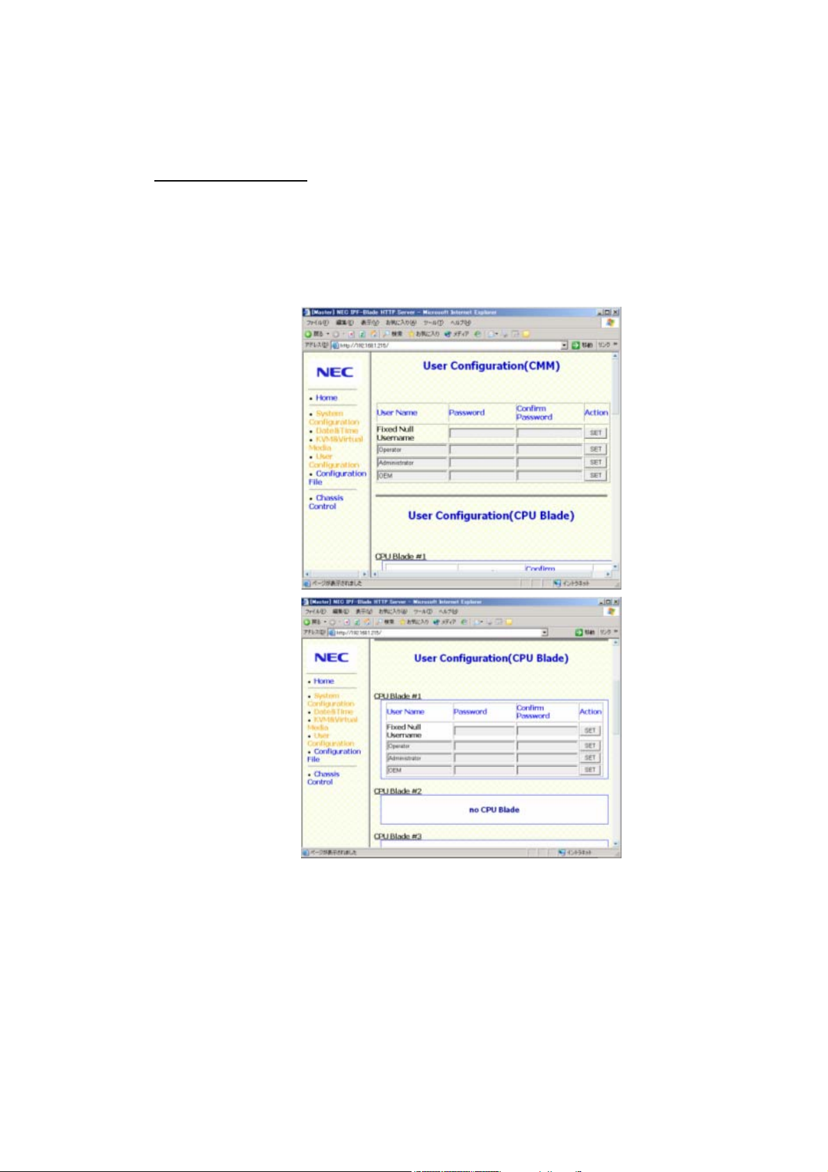
1. User Configuration Menu
User Configuration Menu controls each user’s password for the CMM Blade and the CPU
Blades.
Change the Password
i) Click User Configuration in the left frame.
ii) Type a new password for a user name. (Passwords may be up to 16 characters long
and legal characters are: A-Z, a-z, 0-9.)
iii) Type the password again. (Can not cut & paste from Password column.)
iv) Click SET.
Note: User Name can not be changed.
Figure 2.2-5 User Configuration Menu
2-15
Page 50

2. System Configuration Menu
System Configuration Menu controls SNMP and LAN configuration of the CPU Blades and
the CMM Blade.
a) SNMP Configuration
Click SNMP Configuration or scroll down to SNMP Configuration.
i) Manager IpAddr1/2/3: IP address (IPv4) of SNMP Manager
ii) SecuritySetting: 0-Disable 1-Enable
iii) UDPPortNumber: not supported.
iv) EnableSnmpTrapAck: not supported.
v) CommunityNameTrap: Community name for Trap up to 31 characters.
vi) CommunityNameGet: Community name for “Get” up to 31 characters.
vii) CommunityNameSet: Community name for “Set” up to 31 characters.
viii) SNMP variable (sysContact): System administrator name. Up to 255 characters.
ix) SNMP variable (sysName): System name. Up to 255 characters.
x) SNMP variable (sysLocation): Location where system installed. Up to 255 characters.
xi) SNMP variable (RackMountSystemName): Cabinet name. Up to 63 characters.
xii) SNMP variable (bpLocation): Location in the cabinet (1 Byte).
Special characters other than alphabetic or numeric are counted as
three characters.
Figure 2.2-6 System Configuration Menu
2-16
Page 51

b) CPU Blade LAN Configuration
Click CMM Shared Configuration to set the LAN configuration of each CPU Blade. After
setting the LAN configuration, BMCFW and CMMFW are rebooted automatically (this
could take a few minutes). During BMCFW and CMMFW reboot, the CMM Web Console
and the CMM/BMC/Host Telnet Console can not be used.
i) TimeSynchronize: Synchronize CMM Blade time to one CPU Blade. To disable
TimeSynchronize functionality, select “none”.
ii) AcLink (1-9/ALL): Automatically Power On the CPU Blade when AC power On
iii) Power ON Interval: Interval between each CPU Blade Power ON. (X second)
iv) IpAddr: IP address (IPv4)
v) SubnetMask: Subnet Mask
vi) GatewayIpAddr: Gateway IP address
vii) DefaultGatewayMacAddr: Default Gateway MAC Address
(XX:XX:XX:XX:XX:XX)
Check the Default Gateway MAC address by ‘arp’ command.
viii) LanPortUse: Use of CPU Blade LAN port for CMM and CPU Blade management
communication.
(1: Enable 0: Disable)
Figure 2.2-7 CMM Shared Configuration Menu
2-17
Page 52

c) CMM Blade LAN Configuration
Click CMM LAN Configuration to set the LAN configuration of the CMM Blade. After setting
the LAN configuration, BMCFW and CMMFW are rebooted automatically (this could take a
few minutes). During BMCFW and CMMFW reboot, the CMM Web Console and the
CMM/BMC/Host Telnet Console can not be used.
i) IpAddr: IP address (IPv4)]
ii) SubnetMask: Subnet Mask
iii) GatewayIpAddr Default Gateway IP address
iv) PPCIpAddr: IP Address for KVM switch firmware.
Delete the ARP table manually from the Management PC after
changing the CMM Blade IP Address.
Execute ‘arp -d ip-address’ from the command prompt.
ip-address: New CMM Blade IP address
Figure 2.2-8 CMM LAN Configuration Menu
2-18
Page 53

3. Date & Time Menu
In Date & Time Menu, you can set the Date and Time of the CMM Blade. (YYYY/MM/DD
HH:MM)
Figure 2.2-9 Date & Time Menu
2-19
Page 54

4. Configuration File Menu
In Configuration File Menu, you can save/restore the system configuration and user account
information
a) Save Configuration / User Account / System Event Log (SEL)
i) Click Configuration File.
ii) Click Jump to Download or scroll down to Download.
iii) Save Configuration / User Account Information
- Click CMM Configuration to save the configuration information - “cmmconFigure
bin”.
- Click Account Information to save the account information - “cmmaccinfo.bin”.
Note: Account information of BMC is not saved.
iv) Save SEL
- Click (1)-(21) of CMM SEL or CPU Blade#X to save System Event Log.
- Provide these files to IT or operation personnel in case of system failure.
- SEL can be collected when the system is running.
- File of some links may be empty.
Figure 2.2-10 Configuration File Menu 1
2-20
Page 55

b) Restore Configuration and User Account Information
i) Click Configuration File.
ii) Click Jump to Upload or scroll down to Upload.
iii) Specify an uploading file in the CMM Configuration or Account Information.
iv) Click Upload button to restore the information.
When you upload the CMM Configuration file, the IP address of the CMM
Blade will change instantly. The new IP address may cause a conflict if the IP
Address is used by another system in the same Subnet.
Figure 2.2-11 Configuration File Menu 2
2-21
Page 56

5. KVM & Virtual Media Menu
Remote KVM/VM is used to access EFI/OS console from the CMM Web Console.
Note: JavaVM must be installed on the Management PC to be able to use Remote
KVM/Virtual Media. Use Java VM (J2SE 1.4.2_08 JRE from Sun Microsystems)
included in EXPRESSBUILDER (Directory: ¥DPM¥Setup¥JRE¥).
i) Click START button of the CPU Blade you want to connect KVM or Virtual Media.
Figure 2.2-12 KVM/Virtual Media Menu 1
Express5800/1020Ba with RedHat Enterprise Linux WS2.1/3.0
does not support the Virtual Media function.
2-22
Page 57

ii) Click “KVM&VM reset” button if you want to reset KVMFW.
iii) Click “pagedisabled(toggle)” button if you don’t want to allow Operator and null users to
use the “Virtual Media” button.(Administrator only)
Figure 2.2-13 KVM/Virtual Media Menu 2
6. Chassis Control Menu
Chassis Control Menu is used to control the CPU Blade Power and ID button Control.
Figure 2.2-14 Chassis Control Menu
2-23
Page 58

Power Control:
Select the CPU Blade you want to control and choose Power-ON / Power-OFF (OS
Shutdown) / Reset / Unconditional Power-OFF from the Power Control pull down menu.
Click Apply to Power ON/OFF/RESET the CPU Blade. Use Unconditional Power-OFF when
necessary.
ID Button Control:
Select the CPU Blade you want to control and choose ON / OFF from the ID button Control
pull down menu. Click Apply to turn ON/OFF the CPU Blade ID LED.
To check the latest status of the CPU Blades, click the Reload button of
the Browser or Click “Home” in the left frame.
2-24
Page 59

2.2.4 Local KVM Console
The Local KVM can switch the input/output of the local port between each CPU blade’s VGA /
Keyboard / Mouse. The operation and other settings can be controlled from the Main dialog box.
2.2.4.1 Basic Operation
1. Main Dialog Box
When you press ‘Print Screen’ on your keyboard, the Main dialog box will appear.
Figure 2.2-15 Main dialog box
Table 2.2-3 CPU Blade Status
Status Description
Green
Red x
Online - The server output is ready.
Offline - The server output is not ready. (Power off)
Yellow Updating KVM Firmware.
(Do not power off or remove/insert CPU/CMM Blade.)
Channel The switch output is accessed from...
A :Local KVM
B :Remote KVM
· List of CPU Blades
The CPU Blades mounted in the Blade Chassis.
· Sort Button
Name :alphabetical order
EID :EID order
Slot :numerical order
· Status Symbol
Status of CPU Blades
· Slot Number
Slot Number where the CPU Blades are mounted in the Blade Chassis
· Function Button
Free : Disconnect from CPU Blades.
Clear : Hide the Offline CPU Blades.
Setup : Open Setup Dialog Box
Commands : Open Commands Dialog Box
(Refer to 4. Disconnect from the CPU Blades)
(Refer to 2.2.4.2 Local KVM Configuration)
(Refer to 2.2.4.3 CPU Blade Task Management)
2-25
Page 60

2. Select CPU Blades
Double click the server Name/EID or Slot number or select the server Name/EID and
press ‘Enter’.
3. Select the previous CPU Blade
Press ‘Print Screen’ and then ‘Backspace’. This key combination toggles you between
the previous and current connections.
4. Disconnect from the CPU Blades
Press ‘Print Screen’ and then ‘Alt’ + ‘O’. This leaves the user in a free state, with no CPU
blade selected. The status flag on your console displays “Free”.
5. Using keyboard and mouse
Table 2.2-4 shows other operations using keyboard and mouse.
Table 2.2-4 Keystroke
Keystroke Description
Print Screen Opens the Main Dialog Box.
CTRL+CTRL Pressing ‘CTRL’ key twice opens the Main Dialog Box.
F1 Opens the Help screen for the current dialog box.
Escape Closes the current dialog box without saving changes and returns
to the previous one.
Alt Opens the Dialog Box. Alt+... (Underlined Character located on
the button.) functions the same as clicking the button.
Alt+X Closes the current dialog box and returns to the previous one.
Alt+O Selects the OK button, then returns to the previous dialog box.
Enter Completes a switch operation in the Main dialog box and exits.
Click or Enter In a text box, it selects the text for editing. Press Enter again to
quit the edit mode.
Printscreen
→Backspace
Printscreen
→Alt+0
Printscreen
→Pause
UP/Down Moves the cursor from line to line in lists.
Right/Left Moves the cursor between columns.
PageUp/PageDown Pages up and down through Help pages.
Home/End Moves the cursor to the top or bottom of a list.
Backspace Erases characters in a text box.
Delete Deletes the current selection in the scan list or characters in a text
Shift-Del Deletes from the current selection to the end of the list when
Numbers Types from the keyboard or keypad.
Toggles back to previous selection.
Immediately disengages the user from all CPU Blades. (Status
flag displays “Free”)
Immediately turns on screen saver mode and prevents access to
that specific console, if it is password protected.
box.
editing a scan list.
2-26
Page 61

6. Menu tree
Figure 2.2-16 shows OSD Menu tree.
Figure 2.2-16 OSD Menu tree
2-27
Page 62

2.2.4.2 Local KVM Configuration
Local KVM configuration can be changed from the Setup dialog. Table 2.2-5 explains each
feature which can be changed from the Setup dialog box.
Table 2.2-5 Local KVM Setup Dialog
Feature Description
Menu -Change the server list sorting methods
-Changes the Screen Delay Time before display after pressing ‘Print
Screen’
Flag Change display, timing, color or location of the status flag.
Broadcast Not supported
Scan Set up a custom scan pattern.
ScreenSaver Enable/Disable ScreenSaver, setting Inactivity time.
Keyboard Keyboard Country Code (Not supported)
Names Identify CPU Blades by unique names.
Devices
To access the Setup menu:
1. Press ‘Print Screen’ to launch the Main dialog box.
2. Click “Setup”.
Figure 2.2-17 Setup dialog box
2-28
Page 63

a) Names Dialog Box
i) Click Names in the Setup. The Figure 2.2-18 Names Dialog Box appears.
Note: If a new CPU Blade is discovered, the on-screen list will be automatically updated.
The mouse cursor will change into an hourglass during the update. No mouse or
keyboard input will be accepted until the list update is complete.
ii) Select a server name or port number and click Modify.
Figure 2.2-18 Names Dialog Box
Figure 2.2-19 Name Modify Dialog Box
iii) Type a name in the New Name box. (Up to 15 characters long. A-Z, a-z, 0-9, space,
and hyphen).
iv) Click OK to transfer the new name to the Names dialog box. Your selection is not saved
until you click OK in the Names dialog box. (Click X or press ‘Escape’ to exit the dialog
box without saving changes.)
2-29
Page 64

b) Menu Dialog Box
i) Click Menu in the Setup dialog. The Menu dialog box appears.
ii) Select Name/EID/Port to choose the display order of the CPU Blades.
(Name=alphabetically, EID / Slot=numerically)
Figure 2.2-20 Menu dialog box
iii) Type in the number of seconds (0-9) to delay the Main dialog box display after you
press ‘Print Screen’.
2-30
Page 65

c) Flag Dialog Box
The status flag displays on your desktop and shows the name or EID number of the selected
CPU Blades. Use the Flag dialog box to configure the flag to display by name/EID or to
change the flag color, opacity, display time and location of the desktop.
(‘Free’ indicates that the user has been disconnected from all CPU Blades.)
i) Click Flag in the Setup dialog box. The Flag dialog box appears.
Figure 2.2-21 Flag
Figure 2.2-22 Flag dialog box
ii) Select Name or EID to determine what information will be displayed.
iii) Select Displayed to show the flag all the time or select Timed to display the flag for only
five seconds after switching.
iv) Select a flag color in Display Color.
v) In Display Mode, select Opaque for a solid color flag or select Transparent to see the
desktop through the flag.
vi) To position the status flag on the desktop, click Set Position, right-click on the title bar
and drag to the desired location, and left-click to return to the Flag dialog box.
Figure 2.2-23 Flag dialog box
vii) Click OK to save settings.
2-31
Page 66

d) Scan Dialog Box
In scan mode, the local KVM automatically scans from port to port and displays each CPU
Blade for the number of seconds. The scanning order is determined by placement of the
CPU Blades in the list.
i) Click Scan in the Setup dialog. The Scan dialog box appears.
ii) To add a CPU Blade in the list, type the first few characters of a name or port number.
iii) To delete a CPU Blade from the list, Pres ‘Delete’
iv) To delete all CPU Blades from the list under the selected one, press ‘Shift’+’Delete’
v) To move through the list, press ‘Alt’+’UP’ / ’Alt’+’Down’.
vi) In the Time column, type the number of seconds (from 3-255) of desired time before the
scan moves to the next CPU Blade in the sequence.
vii) Click OK.
Figure 2.2-24 Scan dialog box
2-32
Page 67

Start the Scan Mode
i) Click Commands in the Main dialog box. The Commands dialog box appears.
ii) Select Scan Enable in the Commands dialog box.
iii) Click x to close the Commands dialog box.
Figure 2.2-25 Commands dialog box
Cancel the Scan Mode
i) If the Main dialog box is open, select a CPU Blade, or clear the check box for “Scan
Enable”. If the Main dialog box is not open, move the mouse or press any key (except
“Print Screen” key) on the keyboard.
2-33
Page 68

e) Screen Saver Dialog Box
Screen Saver Configuration
Figure 2.2-26 Security dialog box
i) Click ScreenSaver in the Setup dialog. The Scan dialog box appears.
ii) Type Inactivity Time (from 1-90) and select Mode.
iii) Click Test, and then confirmation dialog box appears. Click “OK” to test Screen Saver
(for about 10 seconds).
Monitor damage can result from the use of Energy mode with
monitors not compliant with ENERGY STAR
®
.
Exit Screen Saver mode
i) Move the mouse or press any key on the keyboard.
f) Devices Dialog Box
Check which CPU Blade you are connecting.
i) Click “Devices” button in Setup Dialog Box (Figure 2.2-17) to open Devices Dialog Box.
ii) Name :alphabetical order, EID :EID order, Slot :Slot numerical order
iii) Click OK.
Figure 2.2-27 Devices dialog box
2-34
Page 69
2.2.4.3 CPU Blade Task Management
From Commands menu, you can engage the scan mode, control user connection, and update
the firmware.
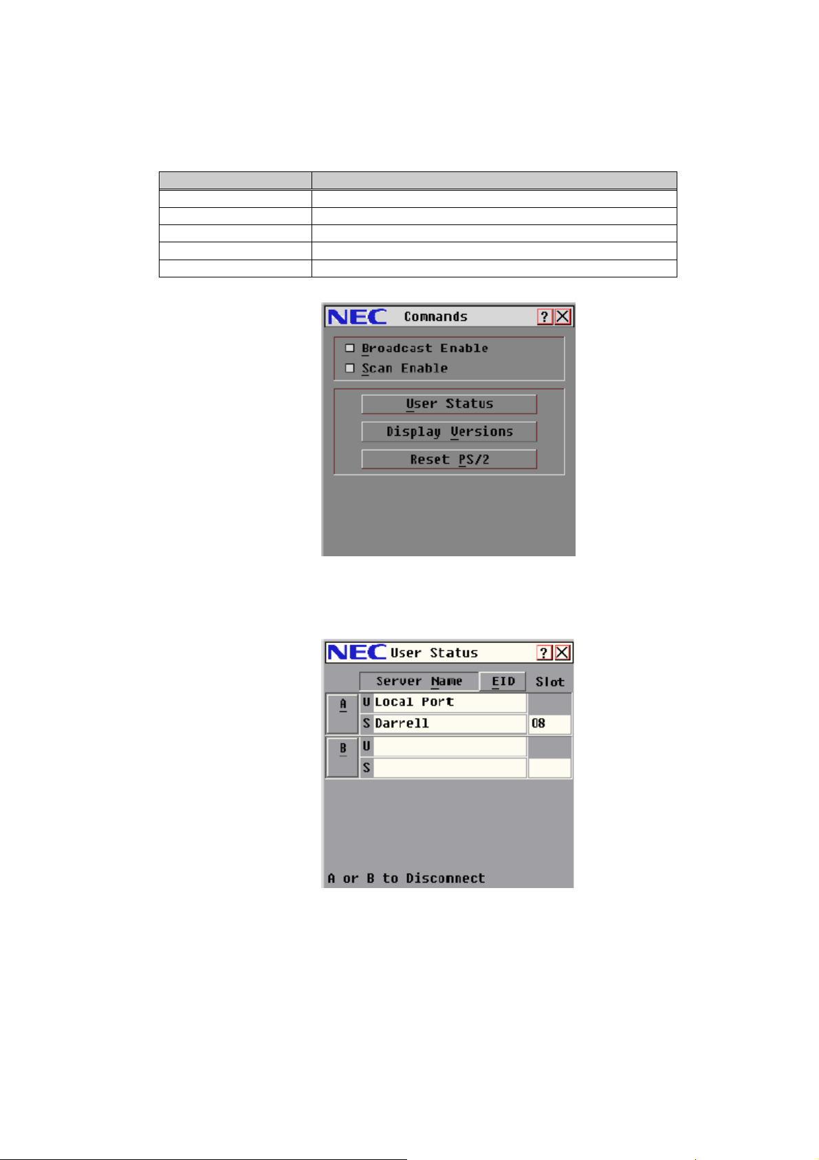
Table 2.2-6 Management Command
Function Description
Broadcast Enable Not Supported
Scan Enable Begin scanning
User Status View and disconnect users
Display versions View version information and update firmware
Reset PS/2 Re-establish operation of keyboard and mouse
a) To view current user connections:
i) Press Print Screen to display the Main dialog box.
ii) Click Commands and then User Status.
Figure 2.2-28 Commands dialog box
Figure 2.2-29 User Status dialog box
2-35
Page 70

iii) Click the letter corresponding to the user to disconnect. The Disconnect dialog box will
appear.
iv) Click OK to disconnect the user. (Type X or press ESC to exit without disconnecting.)
b) Scan Mode
See 2.2.4.2 Local KVM Configuration - d) Scan Dialog Box for more detail.
c) PS/2 Keyboard and Mouse Reset
If your PS/2 keyboard or mouse locks up, you may be able to re-establish operation by
issuing a reset command.
i) Click Commands in the Main dialog box.
ii) Click Reset PS/2.
iii) Click OK to reset the keyboard and mouse.
iv) Click X to close the message box.
d) Version Information
To display version information:
i) Click Commands in the Main dialog box.
ii) Click Display Versions.
Figure 2.2-30 Disconnect dialog box
Figure 2.2-31 Version dialog box
2-36
Page 71

iii) Click DSRIQ to view the KVMFW version of an individual CPU Blade.
iv) Select a CPU Blade and click Version.
Figure 2.2-32 DSRIQ Selection dialog box
Figure 2.2-33 DSRIQ Version dialog box
Forcing the Update of the KVMFW of a CPU Blade
The following procedure describes how to update the KVMFW of a CPU Blade manually.
Normally you do not need to update the KVMFW of a CPU Blade manually.
It takes about 7 minutes to update the KVMFW (CPU Blade) of one CPU Blade. During the
update, the Status Symbol lights yellow and you can not use keyboard and mouse. During
the update, do not turn off the CPU Blade, do not turn the AC power off, and do not reboot or
shutdown the system. If you do, the CPU Blade may need to be repaired.
2-37
Page 72
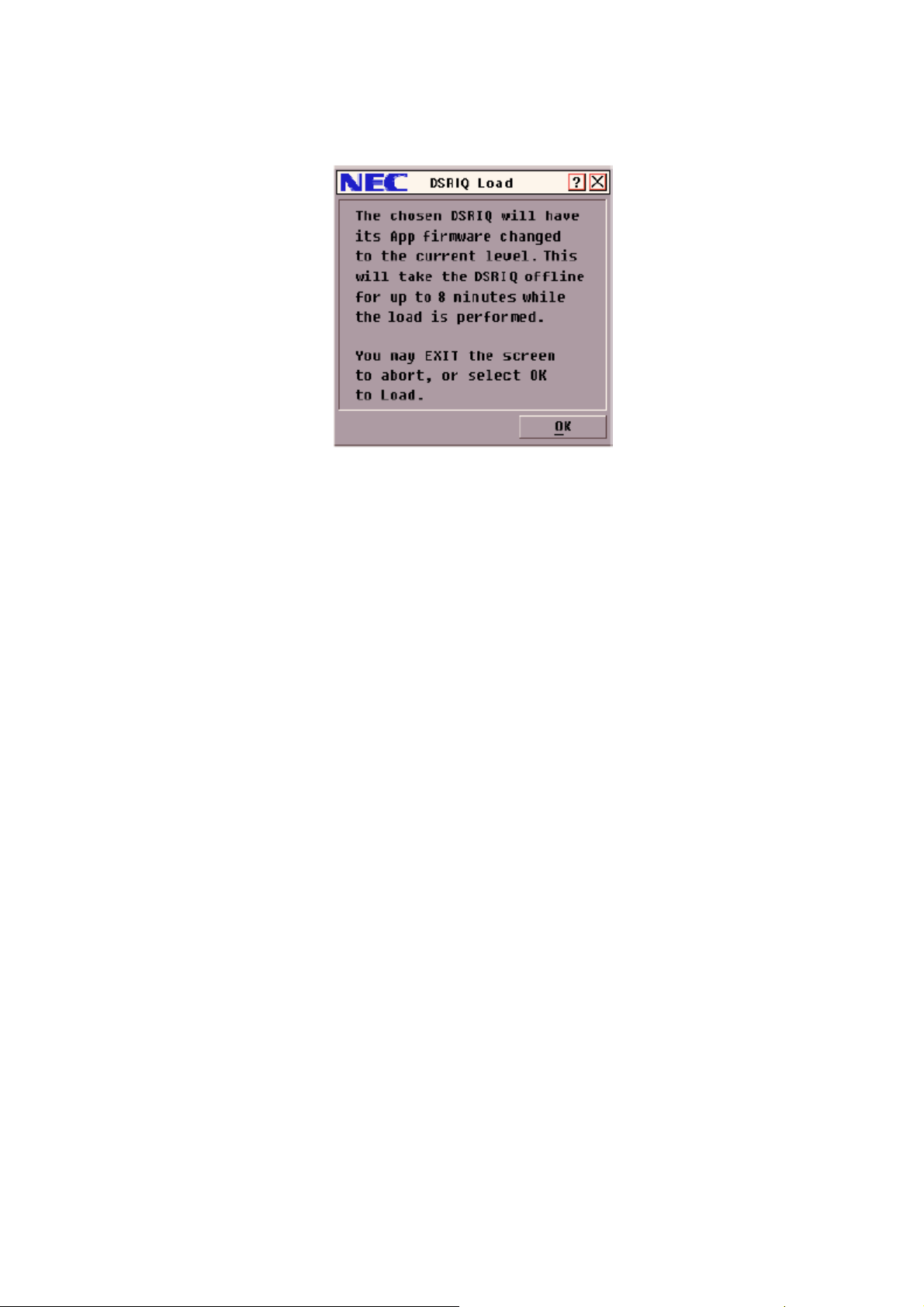
i) Select the CPU Blade for which you want to update the KVMFW in the “DSRIQ
Selection” Dialog Box (Figure 2.2-32), and then click “Version”.
ii) Click “Load Firmware” in “DSRIQ Version” Dialog Box (Figure 2.2-33).
Figure 2.2-34 DSRIQ Load Dialog Box
iii) Click “OK” in the “DSRIQ Load” Dialog Box to update the KVMFW (CPU Blade).
2-38
Page 73

2.2.5 Host Telnet Console
You can open the Host Telnet Console by logging in to an IP address pre-assigned to a CPU
Blade Telnet Management LAN (Port B). When you log in, the Host Telnet Console prompt
(EMS>) will appear. This Telnet Console is shared with the Host Telnet Console and the
Maintenance Telnet Console, the second access and after will be the Maintenance Telnet Console
automatically. You should not use the Maintenance Telnet Console. If your access was to the
Maintenance Telnet Console, you need to close the session and check the other user access.
We recommend Reflection for UNIX and OpenVMS for the terminal emulator.
The emulator settings should be:
1. Set VT-UTF8 for the Terminal Type.
2. Set 25 for the Terminal Line Size.
3. Set special key mapping like ‘CTL’+’Q’
Set ‘CR+LF’ for the New-line if the terminal new line operation does not
work properly.
Be careful when you edit a file in the EFI shell from the Host Telnet
Console, TAB appears to be 8 spaces but it is one character.
If you configure packet buffering, such as STP, on an Ethernet Switch or
Router of the Management LAN, the Host Telnet Console session may
delay 10 to 20 seconds at the beginning. Because of this, you may not be
able to operate BIOS setup and EFI Boot Manager.
In this case, disable packet buffering configuration or use a local or
remote KVM.
Leaving a telnet session open for a given time, the session may be
closed automatically.
2-39
Page 74

2.2.6 Video Viewer
2.2.6.1 Video Viewer system overview
Video Viewer is a Java Application on the Client PC of the Remote KVM system, downloaded
from the CMM Web Console. Video Viewer controls the embedded KVM switch of the Blade
system through the LAN. You can control the Blade system by keyboard and mouse, and see a
screen image of the Blade system on Video Viewer. The Blade system consists of up to 9 CPU
Blades. All CPU Blades are identified by the slot number of the Rack Mount Chassis.
Figure 2.2-35 Remote KVM System Overview
2.2.6.2 Environment
You can use Video Viewer in the following client PC environment. Only one Video Viewer can
be used at one host at the same time. Local KVM and Video Viewer can not be used at the same
time. Disconnect the Local KVM from the CPU Blades, and then you can use Video Viewer.
Client PC environment
a) Supported OS
- Microsoft Windows 2000 Professional or Server with Service Pack 3 or later
- Microsoft Windows XP Home Edition or Professional
b) CPU
- Pentium III / over 1GHz
- Pentium 4 / over 2GHz (recommended)
c) Memory
- more than 256MB
- more than 512MB (recommended)
d) Java VM
- Sun Java J2RE1.4.2_03 to J2RE1.4.2_08
- J2RE1.4.2_07, J2RE1.4.2_08 (recommended)
2-40
Page 75

Install Java
Use the Java Installer included in EXPRESSBUILDER (Directory: ¥DPM¥Setup¥JRE¥) or
on the web site below.
http://www.java.com/
After installing Java, configure the proxy server. If this configuration is incorrect, the Video
Viewer may not boot.
Configure Java VM
1. Boot up “Java Web Start”.
2. Click “File” Æ “Settings”.
3. Open “General” tab.
4. Input the correct information for the proxy server in the “proxy” section.
e) Color configuration
- Pentium III / 1.3GHz or slower: less than 16bit color
- Pentium 4 / 2.5GHz or slower : less than 32bit color
Configure display color
Incorrect settings may cause a display error.
1. Right click on the Desktop screen.
2. Click Properties, then the Properties dialog box appears.
3. Open the Settings tab, and configure color settings.
f) Display Resolution
Supported resolutions at each resolution of the host system are listed below.
: recommended, : supported, : not supported
2-41
Page 76

2.2.6.3 Using Video Viewer
1. Boot up the Video Viewer
1) Open the CMM Web Console.
2) Click “KVM & Virtual Media”.
3) Click the “START” button of the CPU Blade you want to control, then Video Viewer is
booted up.
2. Menu Toolbar
The Menu and buttons for Operation and settings are displayed on Menu Toolbar at the top of
the Video Viewer window. You can customize the buttons on the Menu Toolbar.
3. “File” Menu
You can capture the screen image to a file or the clipboard. And you can also quit the Video
Viewer from the File menu.
a) Capture to Clipboard
b) Capture to File...
c) Exit
Figure 2.2-36 KVM&Virtual Media Menu
Figure 2.2-37 Menu Toolbar
Click “File” Æ “Capture to Clipboard” to capture the screen image to the clipboard.
Click “File” Æ “Capture to File...” to capture the screen image to a file.
Click “File” Æ “Exit” to quit the Video Viewer.
2-42
Page 77

4. “View” Menu
You can configure the following settings.
- Refresh
- Full Screen
- Scaling
- Color
- Connected Users...
Video Viewer is booted up at “1024 x 768” or the automatically adjusted resolution. All
configurations are automatically saved on the client PC.
Refresh
Click “View” Æ “Refresh” to redisplay the current screen.
Full Screen
- Full Screen Mode
Click “View” Æ “Full Screen” to make the Video Viewer window go full-screen. The Menu
Toolbar disappears from the desktop after a short period of time. To make the Menu
Toolbar come back into view, move the mouse pointer to the top of the screen. “Menu
Activation keystroke” performs the same function (see Figure 2.2-49 Session Option -
General tab).
If the display resolution of the client PC is larger than that of the Video Viewer, the outlying
area of the client monitor displays gray.
In Full Screen Mode, “Close” and “Normal Window Mode” buttons are added to the Menu
Toolbar.
Note: In Full Screen Mode, if all area of client monitor is gray, and can not be refreshed,
Note: In Full Screen Mode, resolution settings can not be configured. Before enlarging the
- Cancel Full Screen Mode
Click “Normal Window Mode” on Menu Toolbar, to cancel Full Screen Mode.
force termination of the Video Viewer, and conform the resolution settings of the
client PC to that of the Video Viewer.
Video Viewer window to full-screen, configure the resolution settings correctly.
2-43
Page 78

Scaling
Click “View” Æ “Scaling”.
a) Auto Scale
b) Resolution of the client monitor
Color
You can configure color and compression settings of the Video Viewer. These settings are
configured slot by slot, and given priority over default settings.
Click “View” Æ “Color”, and select color settings listed below.
Note: if “BackGround Refresh” setting is enabled, “Gray Scale / Best compression” can not be
Connected Users
You can check the user names which are logged in to the CMM Web Console (See 2.2.3
CMM Web Console for more information). Click “View” Æ “Connected Users...” to open
“Connected Users Dialog Box” (display the user name).
Automatically adjusts resolution.
Matches the client settings to the Video Viewer resolutions that make the Video Viewer
operation smooth and comfortable.
You can select the Video Viewer resolutions listed below from the “Scaling” Menu.
- Full Scale
- 1024 x 768
- 960 x 720
- 896 x 672
- 832 x 624
- 768 x 576
- 704 x 528
- 640 x 480
- Best Color (Can not be selected)
- Med Color / Med compression (Can not be selected)
- Low Color / High compression
- Gray Scale / Best compression
selected (See 2.2.6.3 Using Video Viewer - 6. “Tools” Menu - Session Option
General tab for more information).
- b)
2-44
Page 79

5. “Macros” Menu
There are two types of macros, “Personal” and “Global”. These macros can be displayed
respectively by the type. You can create and execute macros on the client PC on which the
Video Viewer runs. These macros can be customized and grouped.
Macros functions overview
- You can send a specific set of keystrokes to the Host, such as “Ctrl-Alt-Del”.
- You can group macros.
- You can create, edit, delete and copy macros, and assign arbitrary keystrokes to
- You can create, edit, delete and copy macro groups.
- You can edit, delete and copy the macro group defined as standard.
- You can customize the macro group which is displayed on the tool bar. Settings of
macros.
Note: Newly created macro groups are all “Personal” by default.
grouping macros are independent with respect to each rack mount chassis.
If the “Problem shortcut” dialog box appears when clicking the “help” button, click
the “OK” button of the “Problem shortcut” dialog box. If you click any other dialog
boxes or windows, the “Problem shortcut” dialog box gets behind the dialog
boxes or windows, and then you can input nothing.
2-45
Page 80

Macros Menu function
- Individual macros
Macros registered to the standard macro group are displayed on the tool bar. You can
execute these macros by clicking these on the tool bar.
Note: macros with “Display on Menu” enabled (standard macro group) are listed on the
tool bar.
- Macros
a) Create macros
1) Click “Macros” Æ “Configure” Æ “Macros...” to open “Macros” Dialog Box.
2) Click “Create...” to open “Create Macro” Dialog Box.
3) Input the Macro Name (1-32 characters).
4) Select the keyboard type you want to display from the Keyboard Type pull down
list.
5) Select the Macro Type (Personal / Global).
6) Select the Macro Icon (You can display the Macro Icon on the Menu Toolbar.
See 2.2.6.3 Using Video Viewer - 6. “Tools” Menu - Session Option
information).
7) Click “OK” to create the macro.
8) Click “Reset” to delete all keystrokes in the “Keystrokes” field.
9) To delete partial keystrokes, select the partial keystrokes, and then Click
“Remove”.
10) Click “Cancel” to quit without creating macro.
11) In the “Macros” Dialog Box, click “Run” to execute created macro.
12) Click “Close” to close the “Macros” Dialog Box.
for more
2-46
Page 81

Figure 2.2-38 Macros Dialog Box
Figure 2.2-39 Create Macro Dialog
2-47
Page 82

b) Edit macros
1) Click “Macros” Æ “Configure” Æ “Macros...” to open the “Macros” Dialog Box.
2) Select the macro you want to edit from the “Defined Macros” list, then click the
“Edit” button to open the “Edit Macro” Dialog Box.
3) To change the “Macro Name”, re-enter the “Macro Name” (1-32 characters).
4) To change the Macro Icon, select from the “Macro Icon” pull down list (You can
display the Macro Icon on the Menu Toolbar. See 2.2.6.3 Using Video Viewer -
6. “Tools” Menu - Session Option
5) Click “OK” to save changes and close the “Edit Macro” Dialog Box.
6) Click “Reset” to delete all keystrokes in the “Keystrokes” field.
7) To delete partial keystrokes, select partial keystrokes, and then Click “Remove”.
8) Click “Cancel” to quit without saving edited information.
9) In the “Macros” Dialog Box, click “Run” to execute the created macro.
10) Click “Close” to close the “Macros” Dialog Box.
for more information).
Figure 2.2-40 Edit Macro Dialog Box
c) Delete macros
1) Click “Macros” Æ “Configure” Æ “Macros...” to open the “Macros” Dialog Box.
2) Select the macro you want to delete from the “Defined Macros” list, and then
click “Delete” to open the “Delete Macro” Dialog Box.
3) Click “Yes” to delete, “No” not to delete.
Figure 2.2-41 Delete Macro Dialog Box
2-48
Page 83

d) Copy macros
1) Click “Macros” Æ “Configure” Æ “Macros...” to open the “Macros” Dialog Box.
2) Select the macro you want to copy from the “Defined Macros” list, and then click
“Copy” to open the “Copy Macro” Dialog Box.
3) Input the Macro Name in “Name of copied macro” field (1-32 characters).
4) Select the “Macro Type” (Personal / Global).
5) Click “OK” to copy the macro, “Cancel” not to copy.
Figure 2.2-42 Copy Macro Dialog Box
2-49
Page 84

- Macro groups
a) Create macro groups
1) Click “Macros” Æ “Configure” Æ “Macro Groups...” to open the “Macro Groups”
Dialog Box. Previously-created Macro Groups are listed in the “Defined Groups”
field.
2) Click “Create” to open the “Create Macro Group” Dialog Box.
3) Enter the “Macro Group Name” (1-32 characters).
4) Select the “Group Type” (Global / Personal).
5) Select the macros you want to add to this macro group from the “Macro
Available” list, and then click “Add” to add the selected macros to this macro
group.
6) If you want to delete a macro from this macro group, select the intended macros
from the “Macros In Group” list, and then click “Remove”.
7) Click “OK” to create the macro group and close the “Create Macro Group”
Dialog Box. The created macro group is listed in the Defined Groups. If you
want to quit without creating the macro group, click “Cancel”.
8) To display the macro groups on the tool bar, select the intended macro groups
from the “Defined Groups” list, and then enable “Display on Menu”.
9) Click “Close” to close the “Macro Groups” Dialog Box.
Figure 2.2-43 Macro Groups Dialog Box
2-50
Page 85

Figure 2.2-44 Create Macro Group Dialog Box
2-51
Page 86

b) Edit macro groups
1) Click “Macros” Æ “Configure” Æ “Macro Groups...” to open the “Macro Groups”
Dialog Box. Previously created Macro Groups are listed in the “Defined Groups”
field.
2) Select the macro group you want to edit from the “Defined Groups” list, and then
click “Edit” to open the “Edit Macro Group” Dialog Box.
3) You can change the “Macro Group Name”, add macros to the macro group, and
remove macros from the macro group.
· To change the “Macro Group Name”, re-enter the “Macro Group Name”
(1-32 characters).
· To add macros to the macro group, select the intended macros from the
“Available macros” list, and then click “Add”.
· To delete macros from the macro group, select the intended macros from the
“Macros In Group” list, and then click “Remove”.
4) Click “OK” to save changes and close the “Edit Macro Groups” Dialog Box.
5) Click “Cancel” to quit without saving changes and close the “Edit Macro Groups”
Dialog Box.
6) To Display macro groups on the tool bar, select the intended macros from
“Defined Groups” list, and then enable “Display on Menu”.
7) Click “Close” to close the “Macro Groups” Dialog Box.
Figure 2.2-45 Edit Macro Group Dialog Box
2-52
Page 87

c) Delete macro groups
1) Click “Macros” Æ “Configure” Æ “Macro Groups...” to open the “Macro Groups”
Dialog Box. Previously created Macro Groups are listed in the “Defined Groups”
field.
2) Select the macro groups you want to delete, and then click “Delete”.
d) Copy macro groups
1) Click “Macros” Æ “Configure” Æ “Macro Groups...” to open the “Macro Groups”
Dialog Box. Previously created Macro Groups are listed in the “Defined Groups”
field.
2) Select the macro groups you want to copy, and then click “Copy...” to open the
“Copy Macro Group” Dialog Box.
3) Enter the macro group name in the “Name of copied macro group” field.
4) Select “Group Type” (Personal / Global).
5) Click “OK” to copy, “Cancel” not to copy.
6. “Tools” Menu
You can configure the following settings.
- Automatic Video Adjust
- Manual Video Adjust...
- Session Options...
- Single Cursor Mode
Automatic Video Adjust
Click “Tools” Æ “Automatic Video Adjust” for self-adjustment. During self-adjustment,
“Calibrating” (yellow character) is displayed on the green background.
Manual Video Adjust
Click “Tools” Æ “Manual Video Adjust...” to open the “Manual Video Adjust” Dialog Box. To
adjust the image capture size or pixel sampling, drag the pointer left to decrease or right to
increase the size or sampling of the image. Alternately, you can click on the “+” or “-“ buttons.
The adjusted image is displayed in the background.
Figure 2.2-46 Copy Macro Group Dialog Box
If the “Problem shortcut” dialog box appears when clicking the “help” button, click
the “OK” button of the “Problem shortcut” dialog box. If you click any other dialog
boxes or windows, the “Problem shortcut” dialog box gets behind the dialog
boxes or windows, and then you can input nothing.
2-53
Page 88

A
K
B C D E F G H
I
J
L
Figure 2.2-47 Manual Video Adjust
A : Image Capture Width
B : Pixel Sampling Fine Adjust
C : Image Capture Horizontal Position
D : Image Capture Vertical Position
E : Contrast
F : Brightness
G : Block Noise Threshold
H : Pixel Noise Threshold
I : Automatic Video Adjustment
J : Refresh Image
K : Video Test Pattern
L : Close
2-54
Page 89

a) Image Capture Width, Pixel Sampling Fine Adjust, Image Capture Horizontal Position,
Image Capture Vertical Position
You can adjust any of these functions, image width, pixels, horizontal position, and
vertical position. In normal operation, you do not need to adjust these parameters. These
are adjusted by Automatic Video Adjust. To adjust these parameters correctly, an image
used exclusively for adjustment is required.
b) Contrast, Brightness
When the image is unclear, execute “Automatic Video Adjust” first. Clicking “Tools” Æ
“Automatic Video Adjust” executes self-adjustment a few times. If this do not work,
configure the following settings manually.
First, increment the value of “Brightness” (up to +10). And then change “Contrast” if
necessary. In general, too large of a value for “Contrast” causes the image disappears.
If the packet rate [Pkts/Sec] for “Performance Monitor” (in the “Manual Video Adjust”
Dialog Box) is 0, Click “Refresh Image”. After doing that, if the packet rate does not
change, manual adjustment is completed.
Because the value of “Contrast” is on the large side in the default configuration, turning
down “Contrast” will make medium colors more vivid.
c) Block Noise Threshold, Pixel Noise Threshold
Because of the image noise, unintended packets may be circulated continuously on the
network. Configuring the “Block/Pixel Noise Threshold” setting can reduce the image
noise, and make cursor motion smoother. “Automatic Video Adjust” resets this
configuration.
These are the thresholds of recognition of block, pixel, and color changes. The lower
these thresholds are configured, the better the image contrast becomes, but the network
load increases.
d) Automatic Video Adjust
Click “Automatic Video Adjust” in the “Manual Video Adjust” Dialog Box for
self-adjustment. During self-adjustment, “Calibrating” (yellow character) is displayed on
the green background.
Note: This operation is the same as clicking “Tools” Æ “Automatic Video Adjust”.
e) Refresh Image
Click “Refresh Image” in “Manual Video Adjust” Dialog Box to reload the image in the
Video Viewer window.
Note: This operation is the same as clicking “View” Æ “Refresh”.
f) Video Test Pattern
Click “Video Test Pattern” to display the test pattern image in the background. Click
“Video Test Pattern” again to return to the “Manual Video Adjust” Dialog Box.
g) Close
Click “Close” to return to the Video Viewer window.
2-55
Page 90

Session Option
You can configure the following settings.
- Mouse
- General
- Toolbar
Note: The Help function will be supported in the future.
a) Mouse tab
Click “Tools” Æ “Session Option” to open the “Session Option” Dialog Box.
In the “Mouse” tab, you can configure the following settings.
- Local Cursor
- Mouse Scaling
- Single Cursor Mode
Figure 2.2-48 Session Option - Mouse tab
i) Local Cursor
You can select the cursor shape from 5 shapes, “None”, and “Default”.
1) Click “Tools” Æ “Session Option” to open the “Session Option” Dialog Box.
2) Click the “Mouse” tab.
3) Select the Cursor type from the “Local Cursor” list.
4) Click “Apply”.
5) Click “OK”.
2-56
Page 91

ii) Mouse Scaling
You can configure the mouse motion of the Host.
1) Click “Tools” Æ “Session Option” to open the “Session Option” Dialog Box.
2) Click the “Mouse” tab.
3) Select mouse motion (X:Y) from the “Mouse Scaling” list.
Default: “1:1”, High: “2:1”, Low: “1:2”
4) Select “Custom” and input custom X, Y values (0.25 - 3.00) to modify the
“Mouse Scaling”.
5) Click “Apply”.
6) Click “OK”.
iii) Single Cursor Mode
In Single Cursor Mode, only the mouse cursor of the Host is displayed on the screen
(Local mouse cursor is not displayed.).
1) Click “Tools” Æ “Session Option” to open the “Session Option” Dialog Box.
2) Click the “Mouse” tab.
3) Select a keystroke for canceling Single Cursor Mode from the “Terminating
Keystroke” pull down list.
4) Click “Apply”.
5) Click “OK”.
2-57
Page 92

b) General tab
You can configure the following settings.
- Pass-through Mode setting (in window mode)
- Keystroke for displaying Menu Toolbar
- Display image under Block/Pixel Noise Threshold (See 2.2.6.3 Using Video Viewer
- 6. “Tools” Menu - Manual Video Adjust
Threshold for more information)
1) Click “Tools” Æ “Session Option” to open the “Session Option” Dialog Box.
2) Click the “General” tab.
3) To set or cancel Pass-Through Mode, click on the check box “Pass-through all
keystrokes in regular window mode” to turn it ON or OFF.
4) Select a keystroke for displaying the “Menu Toolbar” from the “Menu Activation
Keystroke” pull down list.
Note: If the “Menu Activation Keystroke” is the same as the “Single Cursor Mode
Terminating Keystroke”, you can not use “Menu Activation Keystroke” in Single
Cursor Mode.
5) To enable or disable “Background Refresh”, click on the “Background Refresh”
- c) Block Noise Threshold, Pixel Noise
check box (in “Background Refresh Selection” section) to turn it ON or OFF. Do not
enable this function in normal operation.
Note: If Background Refresh is enabled, Gray Color/Best compression can not be
enabled (See 2.2.6.3 Using Video Viewer - 4. “View” Menu - Color
information).
6) Click “OK”.
for more
Figure 2.2-49 Session Option - General tab
2-58
Page 93

c) Toolbar tab
You can select the Function buttons displayed on the Menu Toolbar (up to 9 or 10). And
also you can configure the length of time to display Menu Toolbar.
1) Click “Tools” Æ “Session Option” to open the “Session Option” Dialog Box.
2) Click the “Toolbar” tab.
3) Turn ON the check box in the “Display on Toolbar” row to display the function
buttons mentioned above on the Menu Toolbar.
4) To configure the length of time to display the Menu Toolbar, set the integer in the
“Toolbar Hide Delay” field (1-10 [sec]).
5) Click “Apply”.
6) Click “OK”.
Note: If you turn ON the 11th check box of “Display on Toolbar” row, a warning message
appears.
Figure 2.2-50 Session Option - Toolbar tab
2-59
Page 94

Single Cursor Mode
In Single Cursor Mode, only the mouse cursor of the Host is displayed on the screen (Local
mouse cursor is not displayed.).
Click “Tools” Æ “Single Cursor Mode”.
Note: If in full-screen mode, a confirmation dialog box appears.
To terminate Single Cursor Mode, click the “Single Cursor Mode Terminating Keystroke” on
the Menu Toolbar.
7. Help Menu
You can display the version of the Video Viewer. Click “Help” Æ “About Video Session
Viewer” to display the version of the Video Viewer.
8. Align Mouse
You can fit the position of the mouse on the Host and Client. Click “Align Mouse” on the Menu
Toolbar.
Note: If Host and Client mouse acceleration setting are different, two mice may be displayed
Note: After click “Align Mouse”, the mouse cursor moves to the upper left of the screen. If this
- If you want “Single Cursor Mode Terminating Keystroke” not to be displayed on the
Menu Toolbar, turn OFF “Display the toolbar with Single Cursor Mode Exit
instructions” check box.
- If you do not want a confirmation dialog box to appear again, turn ON “Don’t show
this message again” check box. This setting is valid until you change the setting
above (Single Cursor Mode Terminating Keystroke setting).
(See 2.2.6.3 Using Video Viewer - 6. “Tools” Menu - Session Option
tab for more information)
when you move the mouse after alignment.
does not happen, then cancel the mouse acceleration setting on the Host.
- a) Mouse
2-60
Page 95

9. NOTES
During the Video Viewer, some problems (listed below) might occur. For problem resolution,
read the following NOTES.
a) Can not boot up Video Viewer
- Confirm proxy setting of the Java Web Start (See 2.2.6.2 Environment - d) Java VM
for more information).
- Confirm that the CPU Blade is up. If not, Video Viewer can not be started.
b) Displayed image is incorrect or delayed.
- Confirm the color setting on the client PC (see 2.2.6.2 Environment - e) Color
configuration for more information).
c) White and gray characters are obscure.
- Turn down contrast using “Manual Video Adjust” (see 2.2.6.3 Using Video Viewer -
6. “Tools” Menu - b) Contrast, Brightness for more information).
d) Screen turned Solid-gray in full-screen mode, and can not be refreshed.
- Terminate Video Viewer. Configure the screen resolution of the Host and client PC
at the recommended settings or the same settings. After re-configured, enable
full-screen mode again (See 2.2.6.3 Using Video Viewer - 4. “View” Menu - Full
Screen for more information).
e) Can not change the resolution setting in full-screen mode
- Configure the screen resolution setting, and then enable full-screen mode (See
2.2.6.3 Using Video Viewer - 4. “View” Menu - Full Screen
f) Can not set color at gray
- Confirm Background Refresh setting. If this is enabled, gray can not be set (see
2.2.6.3 Using Video Viewer - 6. “Tools” Menu - Session Option
more information).
for more information).
- b) General tab for
2-61
Page 96

g) To restore the initial configuration of the Video Viewer
- If you want to set all parameters back to the initial settings, delete the configuration
file.
Note: If you delete the configuration file, then screen resolution settings, macros,
and macro groups are also deleted.
Location of configuration file (example)
C:¥Documents and Settings¥User Name¥Local Settings¥Application Data¥NEC
Note: “Local Settings” folder may not be displayed depending on the Windows
“hidden files and folders” setting. In order to display it, it may be necessary to
set the “Show hidden files and folders” radio button at Explorer -> Tools ->
Folder Options shown below.
h) Menu Activation Keystroke do not operate
- Confirm what the setting for the “Single Cursor Mode Terminating Keystroke” is. If
this Keystroke is the same as the Menu Activation Keystroke, you can not use the
Menu Activation Keystroke in Single Cursor Mode (see 2.2.6.3 Using Video Viewer
- 6. “Tools” Menu - Session Option
i) The Video Viewer is suddenly terminates
- Wait 5 seconds, then restart the Video Viewer. If you restart without waiting,
“Channel Access Denied.”, “Channel In Use By Local User.” or other error
messages may appear.
The Video Viewer can suddenly terminate because of network, OS, or Java VM
problems.
j) Macros are not displayed normally. Number of toolbars is not correct. Can not perform
macros.
- If one of these problems occurs, delete the configuration file (Refer to g) above to
restore the initial configuration of Video Viewer). Then restart the Video Viewer.
- a) Mouse tab for more information).
2-62
Page 97

2.2.7 Virtual Media
2.2.7.1 Virtual Media system Overview
Virtual Media is the function that allows you to access media on the client PC from the Host
through the LAN.
Figure 2.2-51 Virtual Media System Overview
2.2.7.2 Environment
The supported client PC Environment for Virtual Media is the same as that of Video Viewer.
OS
No. OS support
1 RedHat Enterprise Linux 2.1 not supported
2 RedHat Enterprise Linux 3 not supported
2.2.7.3 Virtual Media function
Access media in the client PC from the Host.
Media
No. Media supported operation
1 Floppy Disk, USB Memory Read/Write
2 CD, DVD Read Only
Note: This function will be supported in future firmware updates.
2-63
Page 98
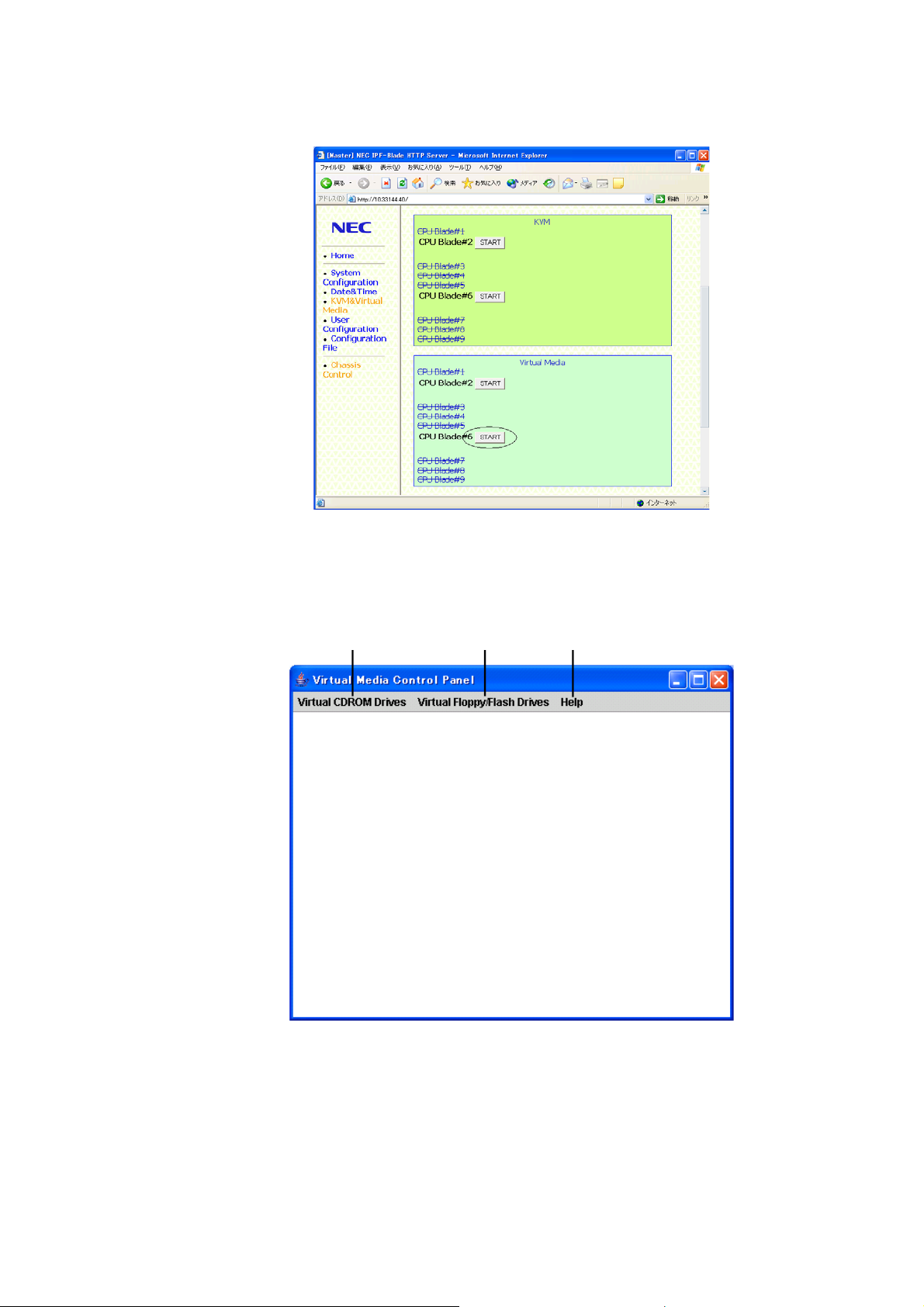
2.2.7.4 Boot up Virtual Media
To use Virtual Media, follow the procedures listed below for both the Client PC and the Host.
a) Control Panel Operation (on the Client PC).
1. Open the CMM Web Console (See 2.2.3 CMM Web Console for more information).
Figure 2.2-52 KVM & Virtual Media menu
2. Insert the media you want to use in Virtual Media into the client PC.
3. Click “START” of the CPU Blade on which you want to use Virtual Media. Then the
Virtual Media Control Panel is started.
4. Available drive menu is displayed on the Menu Toolbar.
A B C
Figure 2.2-53 Virtual Media Control Panel
A : Available CD-ROM devices list, Map None (cancel)
B : Available Floppy/Flash devices list, Map None (cancel)
C : Avocent Virtual Media Client Version
2-64
Page 99

b) Operation on the Host
You can use any of the Media on the client PC from EFI and from Linux on Host.
1. EFI
Connecting/Disconnecting CD-ROM Drives
1) Click the intended CD/DVD-ROM Drive from “Virtual CD-ROM Drives” on the Virtual
Media Menu Toolbar.
2) Execute the “map -r” command from the EFI Shell in the Video Viewer window.
Shell> map –r
Device Mapping table
fs0 : Acpi(PNP0A03,2)/Pci(1F;0)/Pci(1,0)/Scsi(PunF;Lun0)/HD(Part1,SigB0199312
-FAAC-11D8-9134-BAD283D058A9)
fs1 : Acpi(PNP0A03,0)/Pci(1D:0)/Usb(1,0)/CDROM(Entry0)
blk0 : Acpi(PNP0A03,2)/Pci(1F:0)/Pci(1;0)/Scsi(PunF,Lun0)
blk1 : Acpi(PNP0A03,2)/Pci(1F:0)/Pci(1;0)/Scsi(PunF,Lun0)/HD(Part1,SigB0199312
-FAAC-11D8-9134-BAD283D058A9)
blk2 : Acpi(PNP0A03,2)/Pci(1F:0)/Pci(1;0)/Scsi(PunF,Lun0)/HD(Part2,SigB01B1DAE
-FAAC-11D8-9134-BAD283D058A9)
blk3 : Acpi(PNP0A03,2)/Pci(1F:0)/Pci(1;0)/Scsi(PunF,Lun0)/HD(Part3,SigB01B6FE0
-FAAC-11D8-9134-BAD283D058A9)
blk4 : Acpi(PNP0A03,0)/Pci(1D:0)/Usb(1,0)
blk5 : Acpi(PNP0A03,0)/Pci(1D:0)/Usb(1,0)CDROM(Entry0)
blk6 : Acpi(PNP0A03,0)/Pci(1D:0)/Usb(1,1)
Shell>
Figure 2.2-54 EFI Device Mapping Table
3) Input the intended CD-ROM Drive path such as “fs1:” in Figure 2.2-54.
4) To disconnect the Virtual CD-ROM Drive, Click “Virtual CD-ROM Drives” Æ “Map
none (no drive)”.
Connecting/Disconnecting Floppy/Flash Drives
1) Click the intended Floppy/Flash Drive from “Virtual Floppy/Flash Drives” on the
Virtual Media Menu Toolbar.
2) Execute the “map -r” command from the EFI Shell in the Video Viewer window
(Refer to Figure 2.2-54 EFI Device Mapping Table).
3) Input the intended Floppy/Flash Drive path.
4) To disconnect the Virtual Floppy/Flash Drive, Click “Virtual Floppy/Flash Drives” Æ
“Map none (no drive)”.
2-65
Page 100

2. Linux
Commands
Refer to Figure 2.2-55.
1) Check all devices.
# cat /proc/scsi/scsi
2) Check details
# dmasg |grep scsiX
Note: X can be confirmed from the results of the command in 1).
3) Connecting devices
# sudo mount /dev/sdb /mnt/floppy Floppy device (sdb)
# sudo mount /dev/scd0 /mnt/cdrom CD-ROM device (sr0 Æ scd0)
4) List
# ls /mnt/(device name)
5) Copy
Copy all files in the specified device to current directory.
# cp /mnt/(device name)/*
6) Confirm connection status of each device.
# df
7) Disconnect a device.
# sudo umount /dev/scd0 /mnt/cdrom
2-66
 Loading...