

Page 1

User's Guide
NEC Express Server
Express5800 Series
Express5800/T110i
EXP334, 334A
Chapter 1 General Description
Chapter 2 Preparations
Chapter 3 Setup
Chapter 4 Appendix
10.116.02-101.02
ug 2018
A
© NEC Corporation 2018
Page 2

Manuals
Manuals
Manuals for this product are provided as booklets ( ) and electronic manuals ( ) in EXPRESSBUILDER.
Safety Precautions and
Regulatory Notices
Getting Started
EXPRESSBUILDER
PDF
User’s Guide
Chapter 1: General Description Overviews, names, and functions of the server’s parts
PDF
Installation Guide (Windows)
Chapter 1: Installing Windows Installation of Windows and drivers, and precautions for installation
Chapter 2: Preparations Installation of additional options, connection of peripheral devices,
Chapter 4: Appendix Specifications and other information
Chapter 3: Setup System BIOS configurations and summary of EXPRESSBUILDER
Describes points of caution to ensure the safe use of this server.
Read these cautions before using this server.
Describes how to use this server, from unpacking to operations.
See this guide first and read the outline of this product.
and suitable location for this server
PDF
Chapter 2: Installing Bundled
PDF
Maintenance Guide
Chapter 1: Maintenance Server maintenance and troubleshooting
Chapter 2: Useful Features The details of system BIOS settings, RAID Configuration Utility, and
PDF
Other manuals
The details of NEC ESMPRO, Universal RAID Utility, and other features
Installation of NEC ESMPRO, Universal RAID Utility, and other
Software
Chapter 3: Appendix Error messages and Windows Event Logs
bundled software
EXPRESSBUILDER
2
Express5800/T110i User’s Guide
Page 3

Contents
Manuals ................................................................................................................................................................. 2
Contents ................................................................................................................................................................ 3
Contents
Conventions Used in T
Signs and symbols for safety ........................................................................................................................ 6
Notations used in the text .............................................................................................................................. 7
Optical disk drive
Hard disk drive .............................................................................................................................................. 7
Removable media ......................................................................................................................................... 7
Abbreviations of Operating Sy
POST ........................................................................................................................................................... 8
BMC ........................................................................................................................................................... 8
Trademarks ........................................................................................................................................................... 9
License Notification ............................................................................................................................................. 10
Warnings and Additions to T
Latest editions ............................................................................................................................................. 13
Safety notes ................................................................................................................................................ 13
Warning labels ............................................................................................................................................ 14
Handling precautions .................................................................................................................................. 15
Chapter 1 General Description ......................................................................................................................... 17
1. Introduction ................................................................................................................................................. 18
2. Accessories ................................................................................................................................................. 19
his Document .................................................................................................................... 6
........................................................................................................................................... 7
stems ............................................................................................................. 8
his Product and Document ...................................................................................... 13
3. Features ...................................................................................................................................................... 20
3.1
Firmware and Software Version Management ................................................................................. 21
4. Names and Functions of Parts .................................................................................................................... 22
4.1
Front of the Server ........................................................................................................................... 22
Rear View ........................................................................................................................................ 23
4.2
4.3
Internal View .................................................................................................................................... 24
Motherboard .................................................................................................................................... 26
4.4
Indicators ......................................................................................................................................... 27
4.5
4.5.1
POWER LED ( ) ........................................................................................................... 27
4.5.2
STATUS LED 1, 2 (1- -2) ............................................................................................... 27
4.5.3 Global HDD LED (1- -2 ) ............................................................................................... 29
4.5.4
Power Capping LED .......................................................................................................... 29
4.5.5 Optical Disk Access LED ................................................................................................... 29
4.5.6 LED on a hard disk drive ................................................................................................... 30
4.5.7 LINK/ACT LED ( 1, 2, M) ................................................................................... 31
4.5.8 SPEED LED ( 1, 2, M) ....................................................................................... 31
4.5.9 AC POWER LED ............................................................................................................... 31
Chapter 2 Preparations .................................................................................................................................... 32
1. Installing Internal Optional Devices ............................................................................................................. 33
1.1
Safety Precautions ........................................................................................................................... 33
Overview of Installation and Removal .............................................................................................. 34
1.2
1.3 Removing the Side Cover ................................................................................................................ 35
Express5800/T110i User’s Guide
3
Page 4

Contents
1.4 Removing the Front Bezel ............................................................................................................... 36
1.5 TPM Kit ............................................................................................................................................ 37
1.5.1
1.6 DIMM ............................................................................................................................................... 38
1.6.1
1.6.2
1.6.3
1.6.4
1.7 Use of Internal Hard Disk Drives in the RAID System ..................................................................... 42
1.7.1
1.8 Flash Backup Unit for RAID Controller............................................................................................. 46
1.8.1
1.8.2
1.8.3
1.9 PCI Card .......................................................................................................................................... 50
1.9.1
1.9.2
1.9.3
1.9.4
1.9.5
1.9.6
1.10 Power Supply Fan ........................................................................................................................... 58
1.10.1
1.10.2
1.11 HDD Cages and Hard Disk Drives ................................................................................................... 60
1.11.1
1.11.2
1.11.3
1.11.4
1.11.5
1.11.6
1.11.7
1.11.8
1.11.9
1.12 Optical Disk Drive ............................................................................................................................ 75
1.12.1
1.12.2
1.13 Backup Devices ............................................................................................................................... 76
1.13.1
1.13.2
1.14 Supporting High-temperature Environment ...................................................................................... 78
1.15 Connecting Cables .......................................................................................................................... 79
1.15.1
1.15.2
1.16 Attaching the Front Bezel ................................................................................................................. 93
1.17 Installing the Side Cover .................................................................................................................. 94
Installation ......................................................................................................................... 37
Maximum supported memory size ..................................................................................... 39
Installation order ................................................................................................................ 39
Installation ......................................................................................................................... 40
Removal ............................................................................................................................ 41
Notes on setting up a RAID system ................................................................................... 44
Handling precautions ......................................................................................................... 46
Installing the flash backup unit ........................................................................................... 46
Removal ............................................................................................................................ 49
Notes ................................................................................................................................. 51
List of optional devices and installation slots ..................................................................... 52
Installation ......................................................................................................................... 54
Configuration after installing .............................................................................................. 55
Removal ............................................................................................................................ 56
Installing the N8117-01A extra RS-232C connector kit ...................................................... 56
Installation ......................................................................................................................... 58
Removal ............................................................................................................................ 59
Installing a 3.5-inch fixed HDD cage and hard disk drives ................................................. 61
Removing the 3.5-inch fixed hard disk drives .................................................................... 63
Removing the 3.5-inch fixed HDD cage ............................................................................. 64
Installing the 3.5-inch HDD cage and hard disk drives ...................................................... 65
Removing the 3.5-inch hard disk drives ............................................................................. 68
Removing the 3.5-inch HDD cage ..................................................................................... 69
Installing the 2.5-inch HDD cage and hard disk drives ...................................................... 70
Removing the 2.5-inch hard disk drives ............................................................................. 73
Removing the 2.5-inch HDD cage ..................................................................................... 74
Replacing drives ................................................................................................................ 75
Removal ............................................................................................................................ 75
Installation ......................................................................................................................... 76
Removal ............................................................................................................................ 77
Internal interface cables ..................................................................................................... 79
Power cables ..................................................................................................................... 89
2. Installation and Connection ......................................................................................................................... 95
2.1 Installation ........................................................................................................................................ 95
2.1.1
2.2 Connection ....................................................................................................................................... 98
2.2.1
2.2.2
Chapter 3 Setup ............................................................................................................................................. 102
1. Turning on the Server................................................................................................................................ 103
1.1 POST ............................................................................................................................................. 104
1.1.1
1.1.2
2. System BIOS Setup .................................................................................................................................. 107
2.1 Overview ........................................................................................................................................ 107
2.2 Starting SETUP Utility .................................................................................................................... 107
4
Preparation for installation ................................................................................................. 97
Interface cables ................................................................................................................. 99
Power cord ...................................................................................................................... 101
POST sequence .............................................................................................................. 104
POST error messages ..................................................................................................... 106
Express5800/T110i User’s Guide
Page 5

2.3 Description on On-Screen Items and Key Usage .......................................................................... 108
2.4 Cases that Require Setting Changes ............................................................................................. 110
Contents
3. EXPRESSSCOPE ENGINE 3 ................................................................................................................... 1
3.1
Overview ........................................................................................................................................ 112
3.2 EXPRESSSCOPE ENGINE 3 Network Configuration ................................................................... 112
4. EXPRESSBUILDER .................................................................................................................................. 1
4.1
Features of EXPRESSBUILDER ................................................................................................... 114
4.2 Usage of EXPRESSBUILDER ....................................................................................................... 114
5. Installing Software Components
6. Turning off the Server ................................................................................................................................ 1
Chapter 4 Appendix ....................................................................................................................................... 1
1. Specifications ............................................................................................................................................ 118
1.1
Express5800/T110i (EXP334) ........................................................................................................ 118
1.2 Express5800/T110i (EXP334A) ..................................................................................................... 120
2. Interrupt Lines ........................................................................................................................................... 122
3. Glossary .................................................................................................................................................... 123
4. Revision Record ........................................................................................................................................ 125
............................................................................................................... 115
12
14
16
17
Express5800/T110i User’s Guide
5
Page 6

Conventions Used in This Document
Signs and symbols for safety
WARNING and CAUTION are used in this guide as following meaning.
Conventions Used in This Document
WARNING
CAUTION
Precautions and notices against hazards are presented with one of the following three symbols. The individual
symbols are defined as follows:
Attention T
Prohibited
Action
Mandatory
Action
Indicates there is a risk of death or serious personal injury
Indicates there is a risk of burns, other personal injury, or property damage
his symbol indicates the presence of a hazard if
the instruction is ignored.
An image in the symbol illustrates the hazard type.
This symbol indicates prohibited actions. An image
in the symbol illustrates a particular prohibited
action.
This symbol indicates mandatory actions. An
image in the symbol illustrates a mandatory action
to avoid a particular hazard.
(Example)
(Example)
(Example)
(Disconnect a plug)
(Example in this guide)
Symbol to draw
attention
Use only the specified outlet
Use a grounded outlet with the specified voltage. Use of an improper power source
may cause a fire or a power leak.
Description of a warning
WARNING
Term indicating a degree of danger
6
Express5800/T110i User’s Guide
Page 7

Conventions Used in This Document
Notations used in the text
In addition to safety-related symbols urging caution, three other types of notations are used in this document.
These notations have the following meanings.
Important Indicates critical items that must be followed when handling hardware or operating software. If
the procedures described are not followed, server failure, data loss, and other serious
malfunctions could occur.
Note Indicates items that must be confirmed when handling hardware or operating software.
Tips Indicates information that is helpful to keep in mind when using this server.
Optical disk drive
This server is equipped with one of the following drives. These drives are referred to as optical disk drive in this
document.
DVD-ROM drive
DVD Super MULTI drive
DVD Dual drive
Hard disk drive
Unless otherwise stated, hard disk drive described in this document refers to the following.
Hard disk drive (HDD)
Solid state drive (SSD)
Removable media
Unless otherwise stated, removable media described in this document refers to the following.
USB flash drive
Flash FDD
Express5800/T110i User’s Guide
7
Page 8

Conventions Used in This Document
Abbreviations of Operating Systems
Windows Operating Systems are referred to as follows.
See Chapter 1 (1.2 Supported Windows OS) in Installation Guide (Windows) for detailed information.
Notations in this document Official names of Windows
Windows Server 2016 Standard
Windows Server 2016
Windows Server 2012 R2
Windows Server 2012
POST
POST described in this document refers to the following.
Power On Self-Test
BMC
Windows Server 2016 Datacenter
Windows Server 2016 Essentials
Windows Server 2012 R2 Standard
Windows Server 2012 R2 Datacenter
Windows Server 2012 R2 Foundation
Windows Server 2012 Standard
Windows Server 2012 Datacenter
BMC described in this document refers to the following.
Baseboard Management Controller
8
Express5800/T110i User’s Guide
Page 9

Trademarks
Trademarks
EXPRESSSCOPE are registered trademarks of NEC Corporation.
Microsoft, Windows, and Windows Server are registered trademarks or trademarks of Microsoft Corporation in the United States and
other countries.
Intel,
Celeron, Pentium, Core i3, and Xeon are registered trademarks of Intel Corporation of the United States.
All other product, brand, or trade names used in this publication are the trademarks or registered trademarks of their respective
trademark owners.
Express5800/T110i User’s Guide
9
Page 10

License Notification
Open source software of following license is included in the part of this product (system BIOS).
EDK/EDKII
UEFI Network Stack II and iSCSI
Crypto package using WPA Supplicant
License Notification
Open source software of following license is included in the
EDK/EDKII
EDK/EDKII
BSD License from Intel
Copyright (c) 2012, Intel Corporation
All rights reserved.
Copyright (c) 2004, Intel Corporation
All rights reserved.
Redistribution and use in source and binary forms, with or without modification, are permitted provided that the
following conditions are met:
・ Redistributions of source code must retain the above copyright notice, this list of conditions and the following
disclaimer.
・ Redistributions in binary form must reproduce the above copyright notice, this list of conditions and the
following disclaimer in the documentation and/or other materials provided with the distribution.
・ Neither the name of the Intel Corporation nor the names of its contributors may be used to endorse or
promote products derived from this software without specific prior written permission.
part of this product (Off-line Tools).
THIS SOFTWARE IS PROVIDED BY THE COPYRIGHT HOLDERS AND CONTRIBUTORS "AS IS" AND ANY
EXPRESS OR IMPLIED WARRANTIES, INCLUDING, BUT NOT LIMITED TO, THE IMPLIED WARRANTIES OF
MERCHANTABILITY AND FITNESS FOR A PARTICULAR PURPOSE ARE DISCLAIMED. IN NO EVENT
SHALL THE COPYRIGHT OWNER OR CONTRIBUTORS BE LIABLE FOR ANY DIRECT, INDIRECT,
INCIDENTAL, SPECIAL, EXEMPLARY, OR CONSEQUENTIAL DAMAGES (INCLUDING, BUT NOT LIMITED
TO, PROCUREMENT OF SUBSTITUTE GOODS OR SERVICES; LOSS OF USE, DATA, OR PROFITS; OR
BUSINESS INTERRUPTION) HOWEVER CAUSED AND ON ANY THEORY OF LIABILITY, WHETHER IN
CONTRACT, STRICT LIABILITY, OR TORT (INCLUDING NEGLIGENCE OR OTHERWISE) ARISING IN ANY
WAY OUT OF THE USE OF THIS SOFTWARE, EVEN IF ADVISED OF THE POSSIBILITY OF SUCH DAMAGE.
10
Express5800/T110i User’s Guide
Page 11

License Notification
UEFI NETWORK STACK II and iSCSI
OpenSSL License
-------
Copyright (c) 1998-2011 The OpenSSL Project. All rights reserved.
Redistribution and use in source and binary forms, with or without modification, are permitted provided that the
following conditions are met:
1. Redistributions of source code must retain the above copyright notice, this list of conditions and the
following disclaimer.
2. Redistributions in binary form must reproduce the above copyright notice, this list of conditions and the
following disclaimer in the documentation and/or other materials provided with the distribution.
3. All advertising materials mentioning features or use of this software must display the following
acknowledgment:
"This product includes software developed by the OpenSSL Project for use in the OpenSSL Toolkit.
(http://www.openssl.org/)"
4. The names "OpenSSL Toolkit" and "OpenSSL Project" must not be used to endorse or promote products
derived from this software without prior written permission. For written permission, please contact
openssl-core@openssl.org.
5. Products derived from this software may not be called "OpenSSL" nor may "OpenSSL" appear in their
names without prior written permission of the OpenSSL Project.
6. Redistributions of any form whatsoever must retain the following acknowledgment:
"This product includes software developed by the OpenSSL Project for use in the OpenSSL Toolkit
(http://www.openssl.org/)"
THIS SOFTWARE IS PROVIDED BY THE OpenSSL PROJECT ``AS IS'' AND ANY EXPRESSED OR IMPLIED
WARRANTIES, INCLUDING, BUT NOT LIMITED TO, THE IMPLIED WARRANTIES OF MERCHANTABILITY
AND FITNESS FOR A PARTICULAR PURPOSE ARE DISCLAIMED. IN NO EVENT SHALL THE OpenSSL
PROJECT OR ITS CONTRIBUTORS BE LIABLE FOR ANY DIRECT, INDIRECT, INCIDENTAL, SPECIAL,
EXEMPLARY, OR CONSEQUENTIAL DAMAGES (INCLUDING, BUT NOT LIMITED TO, PROCUREMENT OF
SUBSTITUTE GOODS OR SERVICES; LOSS OF USE, DATA, OR PROFITS; OR BUSINESS INTERRUPTION)
HOWEVER CAUSED AND ON ANY THEORY OF LIABILITY, WHETHER IN CONTRACT, STRICT LIABILITY,
OR TORT (INCLUDING NEGLIGENCE OR OTHERWISE) ARISING IN ANY WAY OUT OF THE USE OF THIS
SOFTWARE, EVEN IF ADVISED OF THE POSSIBILITY OF SUCH DAMAGE.
This product includes cryptographic software written by Eric Young (eay@cryptsoft.com).
This product includes software written by Tim Hudson (tjh@cryptsoft.com).
Express5800/T110i User’s Guide
11
Page 12

License Notification
AMI CRYPTO LIBRARY USING WPA SUPPLICANT
WPA Supplicant
-------
Copyright (c) 2003-2016, Jouni Malinen <j@w1.fi> and contributors
All Rights Reserved.
This program is licensed under the BSD license (the one with advertisement clause removed).
If you are submitting changes to the project, please see CONTRIBUTIONS file for more instructions.
License
-------
This software may be distributed, used, and modified under the terms of
BSD license:
Redistribution and use in source and binary forms, with or without modification, are permitted provided that the
following conditions are met:
1. Redistributions of source code must retain the above copyright notice, this list of conditions and the
following disclaimer.
2. Redistributions in binary form must reproduce the above copyright notice, this list of conditions and the
following disclaimer in the documentation and/or other materials provided with the distribution.
3. Neither the name(s) of the above-listed copyright holder(s) nor the names of its contributors may be used to
endorse or promote products derived from this software without specific prior written permission.
THIS SOFTWARE IS PROVIDED BY THE COPYRIGHT HOLDERS AND CONTRIBUTORS "AS IS" AND ANY
EXPRESS OR IMPLIED WARRANTIES, INCLUDING, BUT NOT LIMITED TO, THE IMPLIED WARRANTIES OF
MERCHANTABILITY AND FITNESS FOR A PARTICULAR PURPOSE ARE DISCLAIMED. IN NO EVENT
SHALL THE COPYRIGHT OWNER OR CONTRIBUTORS BE LIABLE FOR ANY DIRECT, INDIRECT,
INCIDENTAL, SPECIAL, EXEMPLARY, OR CONSEQUENTIAL DAMAGES (INCLUDING, BUT NOTLIMITED
TO, PROCUREMENT OF SUBSTITUTE GOODS OR SERVICES; LOSS OF USE, DATA, OR PROFITS; OR
BUSINESS INTERRUPTION) HOWEVER CAUSED AND ON ANY THEORY OF LIABILITY, WHETHER IN
CONTRACT, STRICT LIABILITY, OR TORT (INCLUDING NEGLIGENCE OR OTHERWISE) ARISING IN ANY
WAY OUT OF THE USE OF THIS SOFTWARE, EVEN IF ADVISED OF THE POSSIBILITY OF SUCH DAMAGE.
12
Express5800/T110i User’s Guide
Page 13

Warnings and Additions to This Product and Document
Warnings and Additions to This Product and Document
1. Unauthorized reproduction of the contents of this document, in part or in its entirety, is prohibited.
2. This document is subject to change at any time without notice.
3. Do not make copies or alter the document content without permission from NEC Corporation.
4. If you have any concerns, or discover errors or omissions in this document, contact your sales
representative.
5. Regardless of article 4, NEC Corporation assumes no responsibility for effects resulting from your
operations.
6. The sample values used in this document are not the actual values.
Keep this document for future reference.
Latest editions
This document was created based on the information available at the time of its creation. The screen images,
messages and procedures are subject to change without notice. Substitute as appropriate when content has
been modified.
The most recent version of the guide, as well as other related documents, is also available for download from
the following website.
http://www.nec.com/
Safety notes
To use this server safely, read thoroughly Safety Precautions and Regulatory Notices that comes with your
server.
Express5800/T110i User’s Guide
13
Page 14
Warnings and Additions to This Product and Document
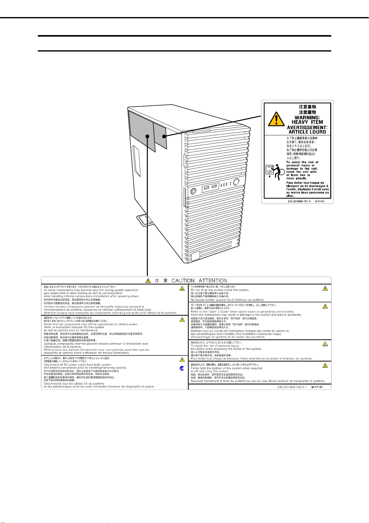
Warning labels
Warning labels are attached on or near the components with potential hazards. These labels are either attached
or printed on the component.
Do not remove or black out this label and keep it clean. If no labels are attached or printed on the server, contact
your sales representative.
14
Express5800/T110i User’s Guide
Page 15

Warnings and Additions to This Product and Document
Handling precautions
Be sure to observe the following precautions for the proper functioning of the server. Ignoring the precautions
may cause server malfunction or failure.
Do not use any cell phones and switch off them near the server. Electric waves from such devices can cause
server to malfunction.
Install the server in an appropriate place. For details, see Chapter 2 (2. Installation and Connection).
If a peripheral device is a not plug-and-play device, make sure that the server is off and unplug the power
cord before connecting/removing cables to/from the devices.
Connect the provided power cord to a 100/200 VAC outlet.
Make sure that the access LED on the server is off before turning off the power or ejecting an optical disk.
Wait for at least 30 seconds before turning on the server after turning off the server. If any Uninterruptible
Power Supply (UPS) unit is connected, set it to wait for at least 30 seconds before turning on the server after
power off.
Do not press the POWER switch to turn on the server before the STATUS LED (amber) is unlit.
Turn off the server and unplug the power cord before moving it.
Regularly clean the server to prevent various types of failure. See Chapter 1 Maintenance (2. Daily
Maintenance) in Maintenance Guide for details.
Momentary voltage drop may occur due to lightning strike. To prevent this, use of UPS is recommended.
We do not guarantee that the server’s optical disk drive will play a copy-protected CD that does not conform
to standards.
In the following cases, check and adjust the system clock before operation.
After transportation
After storage
After the server is used following a period of disuse, in which storage conditions did not conform to those
that guarantee server operations (temperature: 5C to 40C (when the high-temperature environment is
set: 5 to 48°C (it's subject to composition restrictions.)); humidity: 10% to 85% (10% to 80% (when
internal LTO is installed)).
Check the system clock approximately once per month.
We recommend you store the server at room temperature. Keep the following storage conditions.
Temperature: 10C to 55C, Humidity: 10% to 85% (10% to 80% (when internal LTO is installed), No
condensation of moisture)
Do not power off or reset the server, nor disconnect the power cord before POST completes.
If this server, internal optional devices, and media set for the backup devices (tape cartridges) are moved
from a cold place to a warm place in a short time, condensation will occur and cause malfunctions and
failures when these are used in such state. To protect important stored data and property, make sure to wait
for a sufficient period to use the server and components in the operating environment.
Reference: Time effective at avoiding condensation in winter (more than 5C or more differences between
the room temperature and atmospheric temperature)
Disk devices: Approximately 2 to 3 hours T
For optional devices, we recommend you use our NEC products. Even if they are successfully installed or
connected, installation of unsupported devices can cause the server to malfunction or even failure. You will
be charged to repair failure or damage caused by use of such products even within warranty period.
ape media: Appro
ximately 1 day
Express5800/T110i User’s Guide
15
Page 16

Warnings and Additions to This Product and Document
Tips for your health and safety
Using a computer extensively may affect different parts of your body. Here are tips you should follow while working on
a computer to minimize strain on your body.
Keep proper posture
The basic body position for using a computer is sitting straight with
your hands on the keyboard parallel with the floor, and your eyes
directed slightly downward toward the monitor. With the proper
posture described above, no unnecessary strain is applied on any
part of your body, in other words when your muscles are most
relaxed.
Working on the computer with bad posture such as hunching over or
being too close to the monitor could cause fatigue or deteriorated
eyesight.
Adjust the angle of your display
Most display units are designed for adjustment of the horizontal and
vertical angles. This adjustment is important to prevent the screen
from reflecting bright lights and to make the display contents easy to
see. Working without adjusting the display to a comfortable angle
makes it difficult for you to maintain a proper posture and you will
get tired easily. Adjust the viewing angle before use.
Adjust the brightness and contrast of the display
Display screens have functions to control brightness and contrast.
The most suitable brightness/contrast depends on age, individuals,
and environment, so adjust it to suit your preferences. A too bright
or too dark display is bad for your eyes.
Adjust the angle of keyboard
Some keyboards are ergonomically designed, which allow the angle
to be adjusted. Adjusting the angle of the keyboard is effective to
reduce tension on your shoulders, arms, and fingers.
Clean your equipment
Keeping your equipment clean is important not only for the appearance but also for functional and safety reasons. A
dusty monitor makes it difficult to see the display contents, so clean it regularly.
Take rest breaks
When you feel tired, take a break. Light exercise is also
recommended.
16
Express5800/T110i User’s Guide
Page 17

NEC Express5800 Series
Express5800/T110i
General Description
This chapter introduces the features of this server and the name of each part.
1. Introduction
2. Accessories
Describes the accessories of the server.
3. Features
Describes the features of the server and the server management.
4. Names and Functions of Parts
Describes the name of each part contained in the server.
Express5800/T110i User’s Guide
17
Page 18

Chapter 1 General Description
1. Introduction
1.
Introduction
Thank you for purchasing this NEC Express5800 Series product.
This high performance server is powered by the latest Intel processor.
● Intel Xeon Processor
● Intel Core i3 Processor
● Intel Pentium Processor
● Intel Celeron Processor
NEC’s latest technology and architectures realize high-power and high-speed operation that cannot be matched
by existing servers.
The server is designed with consideration of not only reliability but also expandability, which enables you to use
it as a network server.
To use the server correctly and to bring out the server's performance, read this document carefully.
18
Express5800/T110i User’s Guide
Page 19

Chapter 1 General Description
2. Accessories
2.
Accessories
The carton box contains various accessories which are required for setup or maintenance. Make sure you
have them all for future use.
2 Bezel Lock Key
8 Screw for fix to back-up devices
1 or 2
SDR Update CD-ROM
1 or 2
Getting Started
Safety Precautions and Regulatory Notices
*1 EXP334A only
Make sure you have all accessories and inspect them. If an accessory is missing or damaged, contact your
sales representative.
*1
Power Cord
*1
Cable Ties (for securing AC power cord)
Important
The chassis serial number plate and maintenance label is located on the
server. If the serial number does not match the number on the warranty, you
may not be guaranteed against failure even within the warranty period.
Contact your sales representative if they do not match.
Express5800/T110i User’s Guide
19
Page 20

Chapter 1 General Description
3. Features
3.
Features
The server has the following standard features:
High performance
Intel Xeon, Pentium, Core-i3, Celeron
Turbo Boost feature *1
Hyper Threading feature *1
High-speed memory access (DDR4 2400 supported)
High-speed disk access (SATA2 6 Gbps, SAS 12 Gbps supported)
High-speed 1000BASE-T (2 ports) interface
(1 Gbps/100 Mbps/10 Mbps supported)
High reliability
Processor throttle-ring feature
Memory monitoring feature (error correction/error detection)
Memory degeneracy feature (logical isolation of a failed device)
Bus parity error detection
Temperature detection
Error detection
Internal fan monitoring feature
Internal voltage monitoring feature
RAID system (disk array)
Auto rebuild feature (hot swapping supported)
BIOS password feature
processor
The security lock that comes with Front Bezel
HDD (hot swapping supported)
Management utilities
NEC ESMPRO
ExpressUpdate
Remote controlling feature (EXPRESSSCOPE Engine 3)
RAID system management utility (Universal RAID Utility)
Hard disk drive monitoring
Power saving and noiseless design
Power monitoring feature
Power control feature
High-efficiency power supply supporting 80 PLUS
Fan control appropriate to environment, work load, and configuration
Enhanced Intel SpeedStep Technology supported
Cold redundant feature*2
Expandability
Various IO option slots
PCI Express 3.0 (x 16 lanes) : 1 slot
PCI Express 3.0 (x 4 lanes): 1 slot
Platinum / Gold.
PCI Express 2.0 (x 2 lanes): 1 slots
PCI Express 2.0 (x 1 lanes): 1 slots
Large memory of up to 64 GB
Backup device bay provided as standard
USB 3.0 interface (requires the supporting OS)
Three LAN connectors (one for management LAN)
20
Express5800/T110i User’s Guide
Page 21

Chapter 1 General Description
Ready to use
Hard disk drives can be installed with one-touch setup, which requires no cables (requires Hot Plug Drive
Cage Kit)
Various built-in features
El Torito Bootable CD-ROM (no emulation mode) format supported
Software power-off
Remote power-on feature
AC-Link feature
Remote console feature
Baseboard Management Controller (BMC) conforming to IPMI v2.0
Self-diagnosis
Power On Self-Test (POST)
Test and Diagnosis (T&D) utility
Easy setup
EXPRESSBUILDER (OS setup utility)
BIOS setup utility (SETUP)
Maintenance features
Off-line tool
Memory dump feature using the DUMP switch
Feature to back up and restore BIOS/BMC settings using the EXPRESSSCOPE profile key
*1: Supporting this function depends on CPU type.
*2: EXP334A only
3. Features
3.1
Firmware and Software Version Management
You can manage the version of firmware or software on the server and update them with an update package
by using NEC ESMPRO Manager and ExpressUpdate Agent.
This feature automatically updates multiple packages without stopping the system by using NEC ESMPRO
Manager.
Express5800/T110i User’s Guide
21
Page 22

Chapter 1 General Description
4. Names and Functions of Parts
4.
Names and Functions of Parts
The names and the functions of the server's parts are as follows.
4.1
Front of the Server
8
10
11
13
12
15
7
6
4
9
2
8
1
3
5
6
7
14
13
7
6
4
2
1
3
5
6
7
1 POWER Switch
A switch for turning on/off the server. Press once to turn on
the server. POWER LED lights green when it is on. Press it
again to turn off the server. Hold down the switch for four
seconds or more to forcibly turn off the server.
2 DUMP Switch (NMI)
A switch for collecting the memory dump.
Do not press DUMP Switch usually. If DUMP Switch is
pressed, the server stops.
3 BMC RESET Switch
A switch for resetting BMC of this server. Use the switch
only when there is a problem with EXPRESSSCOPE
Engine 3 (BMC).
4 POWER LED (green)
An LED for showing the power status of the server. This
LED lights green when the power is ON.
5 Power Capping LED
An LED for showing the power capping status.
6 STATUS LED1,2 (1:green/2:amber)
An LED for showing the server status. See 4.5 Indicators
for details.
7 Global LED 1, 2 (1:green/2:amber)
An LED for showing the hard disk drive status. See 4.5
Indicators for details.
8 USB Connectors (front)
Connectors for connecting USB interface devices.
9 Optical Disk Drive
An optical disk drive for reading a CD/DVD. Either of the
following optional device can be installed.
(Must install following one certainly.)
– DVD-ROM drive
– DVD SuperMULTI drive
– ODD Bay Cover
The drive provides the following: an eject button to eject the
tray; an LED that indicates the drive access; and an eject
hole to eject the tray forcibly.
10 Key Slot
A slot for Bezel Lock Key that is used to lock Front Bezel.
11 Front Bezel
A cover for protecting the front part of the server.
12 Front Door
A door for covering 5.25-inch devices and optical disk drive.
13 Stabilizer
Stabilizers for supporting the server.
14 HDD Bay
Bays for installing hard disk drives.
15 5.25-inch Expansion Bay
Bays for installing backup devices.
22
Express5800/T110i User’s Guide
Page 23

Chapter 1 General Description
4. Names and Functions of Parts
4.2
6
8
Rear View
<Non-redundant power supply model> <Redundant power supply model>
5
4
5
1
9
3
6
10
10
9
7
2
8
4
9
10
10
9
7
2
1
3
1 AC Inlet
Sockets for connecting power cords.
2 PCI Slots
Slots for installing PCI cards.
3 Chassis Lock Tab
A tab for locking the side cover.
4
Serial Port (COM A) Connector
A connector for connecting serial interface devices.
This cannot directly connect to a network line. If the
optional N8117-01A Additional RS232C Connector Kit is
connected, the connector of N8117-01A is assigned as the
serial port B.
5 Display Connector
A connector for connecting a display
6 USB Connectors
Connectors for connecting USB3.0 interface devices.
7 LAN Connectors
Connectors for connecting to a network
(1000BASE-T/100BASE-TX /10BASE-T).
If Shared BMC LAN feature is enabled in ROM Utility, LAN1
connector can also be used as the management LAN
connector. Sharing port is not recommended from the point
of performance and security.
8 Management LAN Connector
A LAN connector (1000BASE-T/100BASE-TX /10BASE-T)
for connecting EXPRESSSCOPE Engine 3. This connector
cannot be used as a normal LAN port.
used when Shared BMC LAN feature is used.
9 LINK/ACT LED (green)
LEDs for showing the access status of LAN
10 SPEED LED (green/amber)
LEDs for showing the transfer speed of LAN ports
This port cannot be
Express5800/T110i User’s Guide
23
Page 24

Chapter 1 General Description
4. Names and Functions of Parts
4.3
Internal View
<Non-redundant power supply model>
The images below do not show the duct.
1 3
9
2
8
10
6
5
4
1 Power Supply Unit
2 Cooling Fan (CPU)
3 DIMM Slots
4 Hard Disk Drive Bay
The figure shows the view when 2.5-inch hard disk drives
are installed.
5 Optical Disk Drive
7
6 5.25-inch Expansion Bay
A bay to mount the backup device.
7 Motherboard
8 PCI Slot
9 Cooling Fan (rear)
10 Cooling Fan (for cooling Power Supply Unit)
24
Express5800/T110i User’s Guide
Page 25

Chapter 1 General Description
<Redundant power supply model>
The images below do not show the duct.
4. Names and Functions of Parts
1
9
2
8
3
6
5
4
7
1 Power Supply Unit
2 Cooling Fan (CPU)
3 DIMM Slots
4 Hard Disk Drive Bay
The figure shows the view when 2.5-inch hard disk drives
are installed.
5 Optical Disk Drive
6 5.25-inch Expansion Bay
A bay to mount the backup device.
7 Motherboard
8 PCI Slot
9 Cooling Fan (rear)
Express5800/T110i User’s Guide
25
Page 26

Chapter 1 General Description
4. Names and Functions of Parts
4.4
Motherboard
18
17-(1)
17-(2)
9
17-(3)
17-(4)
2
12
26
28
20
27
2
1-(2)
1-(4)
19
1-(1)
1-(3)
2
3
5
4
25
21
13
23
7
8
16
15
1 DIMM Slots (the number after hyphen indicates DIMM
number)
2 Power Connector
3 CPU Socket
4 CPU Cooling Fan Connector (FAN1)
5 RAID LED Cable Connector
6 Serial ATA Connector (for ODD)
7 Lithium Battery
8 Buzzer
9 Clear CMOS Jumper
10 RAID Configuration Jumper
11 Clear Password Jumper
12 Rear Fan Connector (FAN2)
13 USB Connector (for front)
14 Front Panel Cable Connector
15 Serial Port (COM B) Connector (for N8117-01A)
16 SPI Flash Mezzanine Connector
EXPRESSSCOPE profile key (SPI memory) has been
installed, where BIOS and BMC configuration data is
stored. Move it when replacing MB to keep using the data.
24
10
1114
22
6
17 PCI Card Slots
17-(1) PCI EXPRESS x2 (x8 connector)
17-(2) PCI EXPRESS x1 (x8 connector)
17-(3) PCI EXPRESS x16 (x16 connector)
17-(4) PCI EXPRESS x4 (x8 connector)
18 External Connector
19 Power Supply Unit Fan Connector (FAN3)
20 PMBus Connector
21 TPM Kit Connector
22 Mini-SAS HD Connector
23 USB Connector (for internal)
24 HDD BP Connector
25 Dust Proof Sensor Cable Connector
26 Fan Configuration Jumper
27 Power Supply Unit Configuration Jumper
28 High Temperature Support
Option Configuration
Jumper
26
Express5800/T110i User’s Guide
Page 27

Chapter 1 General Description
A
4. Names and Functions of Parts
4.5
4.5.1
Indicators
This section explains the meanings of the following LEDs.
Front view
Optical disk access LED STATUS LED1,2
POWER LED POWER CAPPING LED Global HDD LED1,2
DISK LED1,2
C POWER LED
POWER LED ( )
LINK/ACT LED
SPEED LED
Rear view
4.5.2
POWER LED indicates the power ON/OFF status of the server.
POWER LED pattern Description
On (green) The server is normally powered on.
Off The server is off-powered.
The server is in halt status.
STATUS LED 1, 2 (1- -2)
While hardware is operating normally, STATUS LED 1 lights green. STATUS LED 2 is off.
STATUS LED 1 is off or STATUS LED 2 lights/flashes amber if there is a hardware failure.
The next table lists STATUS LED patterns, their description and action. If the LED indication does not
change even if the action below is performed, contact your sales representative.
Tips
Refer to the system event log (SEL) by using NEC ESMPRO or the offline
maintenance utility to view the cause of failure.
Express5800/T110i User’s Guide
27
Page 28

Chapter 1 General Description
4. Names and Functions of Parts
STATUS LED 1, 2 pattern
STATUS LED 1 STATUS LED 2
On (green) Off The server is operating normally. –
On (green) On (amber) Initialization of BMC is in progress. Wait until initialization completes.
Blinking (green) Off Memory is in a degraded state Find the device in degraded state by using
A correctable memory error has often
occurred.
Operating while CPU error is detected.
In redundant power configuration, power is
not supplied to either of power unit.
Off Off The power is off. Turn on the server.
POST is in progress. Wait for a while. STATUS LED will turn green
Watchdog timer expired. Turn off the power and then turn it on.
Memory dump is being requested.
Note: The LED remains green if the dump is
caused by software.
Off
Off Blinking (amber) Power Supply Unit is failing (in power
On (amber) A temperature alarm was detected. Check the internal fan for dusts. Also check if
A CPU error occurred. Turn off the power and then turn it on.
A PCI system error occurred
A PCI parity error occurred
A PCI bus error occurred.
A voltage alarm was detected. Contact your sales representative.
Sensor error was detected.
A CPU temperature alarm was detected.
An error occurred on Intel Node Manager
(one of the features of EXPRESSSCOPE
Engine 3).
redundant configuration).
A fan alarm was detected. Check if the internal fan cable is properly
A temperature warning was detected. Check the internal fan for dusts. Also check if
A voltage warning was detected Contact your sales representative.
One or more hard disk drives are failing
(Only when a RAID system configuration
was built hot-plug HDD).
Description Action
BIOS Setup Utility (SETUP), and replace it as
soon as possible.
after POST completes.
If POST displays any error message, take
notes of the message, and contact your sales
representative.
Wait until the memory dump is completed.
the fan unit is properly connected.
If POST displays any error message, take
notes of the message, and contact your sales
representative.
Contact your sales representative.
connected.
the fan unit is properly connected.
28
Express5800/T110i User’s Guide
Page 29

Chapter 1 General Description
4. Names and Functions of Parts
4.5.3
Global HDD LED (1- -2 )
Global HDD LED indicates the status of the internal hard disk drive or optical disk drive.
Global HDD1, 2 LED pattern
Global HDD LED 1 Global HDD LED 2
On/blinking (green) Off All Accessing to hard disk drive or
Off On (amber) In case that RAID is constituted with
optional RAID controller. In case that
RAID is constituted with 3.5-inch or
2.5-inch Hot Plug Drive Cage Kit.
Blinking (green) Blinking (amber) Rebuilding is in progress.
Off Off All No access and No HDD fault
Configuration Description
optical disk drive.
Hard disk drive is failing.
The LED may be lit few seconds
after power is turned on or reset,
and this is normal behavior.
4.5.4
Power Capping LED
Power Capping LED indicates enabled/disabled status of Power Capping feature as shown below.
Power Capping LED pattern Description
On (green) Power Capping feature is enabled.
Blinking (green) Power Capping is enabled and power control (capping) is working.
Off Power Capping feature is disabled.
4.5.5
Optical Disk Access LED
The LED lights/blink when a CD/DVD the media set on the optical disk drive is being accessed.
Express5800/T110i User’s Guide
29
Page 30

Chapter 1 General Description
4. Names and Functions of Parts
4.5.6
LED on a hard disk drive
If 3.5-inch or 2.5-inch Hot Plug Drive Cage Kit is installed, each drive has its respective LED (Disk LED).
DISK LED 2 (amber)
DISK LED 1 (green)
-
DISK1 LED 1,2 pattern
DISK LED 1 DISK LED 2
On/blinking (green) Off 3.5-inch or 2.5-inch
Off On (amber) RAID constitution
Blinking (green) Blinking (amber)
Off Off 3.5-inch or 2.5-inch
Configuration
Hot Plug Drive Cage
Kit is installed.
that 3.5-inch or
2.5-inch Hot Plug
Drive Cage Kit is
installed.
Hot Plug Drive Cage
Kit is installed.
DISK LED 1 (green)
DISK LED 2 (amber)
3.5-inch Hard Disk Drive
Description Action
Hard disk drive is being
accessed.
-
Hard disk drive is failing. Contact your sales
representative.
Rebuilding is in progress.
Hard disk drive is halted.
-
-
Important
Observe the following precautions whenever you use the auto rebuilding
feature.
Do not turn off or reboot the server while a HDD is being rebuilt.
Wait at least 90 seconds before installing a HDD after removing one.
Do not replace a HDD while another HDD is being rebuilt.
30
Express5800/T110i User’s Guide
Page 31

Chapter 1 General Description
4. Names and Functions of Parts
4.5.7
4.5.8
LINK/ACT LED ( 1, 2, M)
This LED indicates the status of the LAN port.
LINK/ACT LED pattern Description
On (green) The server is correctly connected with network.
Blinking (green) The server is accessing network.
Off The server is disconnected from network.
SPEED LED ( 1, 2, M)
This LED indicates which network interface is used.
Two onboard LANs ( 1, 2) support 1000BASE-T, 100BASE-TX, and 10BASE-TX.
Management LAN ( M) supports 100BASE-TX and 10BASE-TX.
SPEED LED pattern Description
On (amber) The port is operating with 1000BASE-T interface.
On (green) The port is operating with 100BASE-TX interface.
Off The port is operating with 10BASE-T interface.
4.5.9
AC POWER LED
If an optional redundant power supply unit is installed, an AC POWER LED is added to the unit.
LED status Condition Description
On (green) The server is on.
Blinking (green) AC power is being supplied via the
power cord.
Cold redundancy is enabled.
On (amber) A redundant power supply system is
configured and a power cord is only
connected to one of the power supply
units.
The power supply unit detects
abnormality and stops because
safety.
Blinking (amber) The power supply unit is detecting an
omen of an abnormal.
Off The power is not supplied to the
server.
Connect the power cord to the other power
supply unit.
Contact your sales representative.
Connect the power cable. If the LED is
not lit although power cord is connected,
contact your sales representative.
Express5800/T110i User’s Guide
31
Page 32

NEC Express5800 Series
Express5800/T110i
This chapter describes preparations for using this server.
1. Installing Internal Optional Devices
Describes how to install or remove optional devices.
You can skip this section if you did not purchase any optional devices.
2. Installation and Connection
Place the server in a proper location and connect some cables following this section.
Preparations
32
Express5800/T110i User’s Guide
Page 33

Chapter 2 Preparations
1. Installing Internal Optional Devices
1.
1.1
Installing Internal Optional Devices
This chapter describes the instructions for installing supported optional devices and precautions.
If you did not purchase any optional device requiring installation, you can skip this section.
Important
Safety Precautions
Be sure to observe the following precautions to install and remove optional devices properly and safely.
If you use the third party optional device to the server, and it causes failure, a
charge for repairing must be paid even within the warranty period.
WARNING
Be sure to observe the following precautions to use the server safety. Failure to
observe the precautions may cause death or serious injury. For details, refer to
Safety precautions and Regulatory Notices.
Do not disassemble, repair, or modify the server.
Do not remove the lithium, NiMH, or Li-ion battery.
Do not handle the server while the power plug is inserted into the outlet.
CAUTION
Be sure to observe the following precautions to use of the server safely. Failure
to observe the precautions may cause burns, injury, and property damage. For
details, refer to Safety precautions and Regulatory Notices.
Do not attempt to lift the server by gripping the front bezel or vent holes cover.
Make sure to complete installation.
Do not get your fingers caught.
High temperature.
Express5800/T110i User’s Guide
33
Page 34

Chapter 2 Preparations
1. Installing Internal Optional Devices
1.2
Overview of Installation and Removal
Install/remove components by using the following procedure.
1. Turn the server off.
See Chapter 3 (6. Turning off the Server).
2. Disconnect all the power cables connected to the server from the outlet, and then disconnect them
from the server.
3. Disconnect all cables connected to the connector at the rear.
4. Remove the side cover.
See Chapter 2 (1.3. Removing the Side Cover).
5. Remove the front bezel if applicable.
See Chapter 2 (1.4 Removing the Front Bezel).
6. Depending on the components to be installed or removed, follow the procedure in order.
See Chapter 2 (1.5 TPM Kit to 1.13 Backup Devices).
7. Connect cables
See Chapter 2 (1.15 Connecting Cables).
8. Attach the front bezel.
See Chapter 2 (1.16 Attaching the Front Bezel).
9. Attach the side cover.
See Chapter 2 (1.17 Installing the Side Cover).
Continue the setup while referring to Chapter 2 (2.2 Connection).
34
Express5800/T110i User’s Guide
Page 35

Chapter 2 Preparations
1. Installing Internal Optional Devices
1.3
Removing the Side Cover
Remove the side cover by using the following procedure.
1. See steps 1 to 3 in Chapter 2 (1.2 Overview of Installation and Removal) for preparations.
2. Unlock the chassis, if necessary.
3. Remove the two screws on the rear panel.
4. Remove the side cover, holding it firmly.
5. Remove the front bezel, if necessary.
Carefully lay the unit on its side, right side down.
Express5800/T110i User’s Guide
35
Page 36

Chapter 2 Preparations
1. Installing Internal Optional Devices
1.4
Removing the Front Bezel
Remove the front bezel by using the following procedure.
1. See steps 1 to 3 in Chapter 2 (1.2 Overview of Installation and Removal) for preparations.
2. Using the indentation on the left side of the front bezel,
pull the front bezel forward until the tab pops out of the
frame.
3. Continue opening the front bezel until the three tabs on
the right side of the server pop out and the front bezel
is completely removed.
4. Carefully lay the server on its side, right side down.
36
Express5800/T110i User’s Guide
Page 37

Chapter 2 Preparations
1. Installing Internal Optional Devices
1.5
1.5.1
TPM Kit
This section describes the procedure for installing optional TPM Kit.
Installation
TPM kit connector
Install the TPM Kit in accordance with the following procedure.
Note The TPM kit once installed cannot be removed.
1.
See steps 1 to 5 in Chapter 2 (1.2 Overview of Installation and Removal) for preparations.
Install the TPM Kit and secure it by
2.
pushing the nylon rivet that comes with
the TPM Kit.
Express5800/T110i User’s Guide
37
Page 38

Chapter 2 Preparations
1. Installing Internal Optional Devices
1.6
DIMM
Install a Dual In-line Memory Module (DIMM) to a DIMM slot on the motherboard in the server. The
motherboard provides four slots to install DIMMs.
Up to 64 GB (16GB 4) of memory can be installed.
Important
Tips
Use only the DIMMs specified by NEC.
Avoid static electricity to work with the procedure below. For details, see
Chapter 1 (1.8 Anti-static measures) in Safety Precautions and Regulatory
Notices.
As about 750 MB of memory is used for PCI resources, the available memory size
may be less than the mounted memory size.
DIMM2
DIMM4
DIMM1
DIMM3
Rear
Motherboard
This server supports 2-way Interleave mode.
In 2-way interleaved memory system, the data transfer rate of the memory is twice that of a non-interleaved
memory system.
Front
38
Express5800/T110i User’s Guide
Page 39

Chapter 2 Preparations
1.6.1
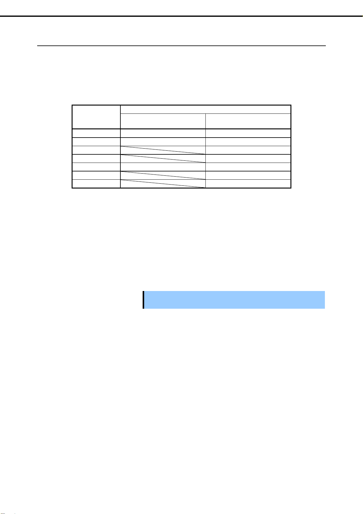
Maximum supported memory size
The maximum available memory size on the server depends on the architecture (x86 architecture) and OS
specs.
A list of maximum memory sizes
1. Installing Internal Optional Devices
Windows Server 2012 Standard
Windows Server 2012 Datacenter
Windows Server 2012 R2 Standard
Windows Server 2012 R2 Datacenter
Windows Server 2016 Standard
Windows Server 2016 Datacenter
Windows Server 2016 Essentials
VMware ESXi 6.0 Update3 6 TB 64 GB
VMware ESXi 6.5 Later
1.6.2
Installation order
Install DIMMs one by one in order of increasing memory size into slots in the order of DIMM#1, DIMM#2,
DIMM#3, and DIMM#4. If you want to run the server in 2Way Interleave mode, observe the following
installation rules:
OS
The maximum memory size
supported on each OS
4 TB 64 GB
24 TB
64 GB
12 TB 64 GB
The maximum memory size
Up to 4 TB of the main memory is
available to each virtual machine.
Up to 6 TB of the main memory is
available to each virtual machine.
supported on the server
Install DIMMs in pairs
The two DIMMs installed together must be of the same specifications and memory size.
Install the pairs as DIMM#1 and DIMM#2, or DIMM#3 and DIMM#4. The installation order between the
pairs does not matter.
Installation examples
Example 2Way Interleave DIMM#1 DIMM#2 DIMM#3 DIMM#4
1 Available 4 GB DIMM 4 GB DIMM Not installed Not installed
2 Available 4 GB DIMM 4 GB DIMM 4 GB DIMM 4 GB DIMM
3 Not available 4 GB DIMM 4 GB DIMM 4 GB DIMM Not installed
4 Not available 4 GB DIMM 4 GB DIMM Not installed 4 GB DIMM
Express5800/T110i User’s Guide
39
Page 40

Chapter 2 Preparations
1.6.3
Installation
Install a DIMM by using the following procedure.
1. See steps 1 to 5 in Chapter 2 (1.2 Overview of Installation and Removal) for preparations.
2. Hold the server with both hands and slowly and gently lay it so that the left side faces upward.
3. Open both levers of the target DIMM slot outward.
4. Hold the DIMM vertically and push it into
the slot.
When the DIMM is inserted correctly, the
lever automatically closes.
1. Installing Internal Optional Devices
Notch
Key
Important
Note Align the notch on the DIMM with the key on the slot.
5. Firmly close the lever.
6. Continue to install or remove internal optional devices, mount and connect the server, and turn it on.
7. Confirm that no error messages are displayed in POST screen.
If any error messages are displayed, see Chapter 3 (1. POST Error Message) in "Maintenance Guide".
8. Run the BIOS Setup Utility, go to the Advanced menu, and check the Memory Configuration.
Confirm that the added DIMM has been recognized in the BIOS. Confirm that the applicable DIMM
Group Status is set to "Normal". See Chapter 2 (1. System BIOS) in "Maintenance Guide".
9. Set the paging file size to the recommended value (Total memory size x 1.5) or more.
When using a Windows OS, see Chapter 1 (7.1 Specifying Memory Dump Settings (Debug
Information)) in "Installation Guide (Windows)".
For other OS, see the manual provided with the operating system or contact your sales representative.
Do not apply too much pressure when you push a DIMM into the socket.
40
Express5800/T110i User’s Guide
Page 41

Chapter 2 Preparations
1.6.4
Removal
Remove a DIMM in the following procedure.
1. Installing Internal Optional Devices
Note
1. See steps 1 to 5 in Chapter 2 (1.2 Overview of Installation and Removal for preparations.
2. Open both levers of the target DIMM slot
outward.
The DIMM is unlocked
3. Remove the DIMM by pulling it out from
the slot in a straight direction.
Important
4. Assemble the server.
5. Turn on the server and confirm that no error messages are displayed on POST. If any error message is
displayed, see Chapter 3 (1. Post Error Message) in "Maintenance Guide".
When removing a defective DIMM, check error messages displayed at POST or
NEC ESMPRO and check the DIMM slot where the defective DIMM is installed.
At least one DIMM needs to be installed for the server to operate.
Do not apply too much pressure when you pull a DIMM out from the
socket.
6. If you replaced a broken DIMM, choose Yes in Memory Configuration-Memory Retest of the
Advanced menu, and then choose Save Changes and Exit to restart.
7. Set the paging file size to the recommended value (Total memory size x 1.5) or more.
When using a Windows OS, see Chapter 1 (7.1 Specifying Memory Dump Settings (Debug
Information)) in "Installation Guide (Windows)".
For other OS, see the manual provided with the operating system or contact your sales representative.
Express5800/T110i User’s Guide
41
Page 42

Chapter 2 Preparations
1. Installing Internal Optional Devices
1.7
Use of Internal Hard Disk Drives in the RAID System
This section describes how to use the hard disk drives installed in the HDD cage at the front of the server in
the RAID system.
Important
Note
Tips
To build a RAID system, change the jumper switch on motherboard, as shown below.
If you use hard disk drives in the RAID system or change the RAID level,
initialize the hard disk drives. If the hard disk drive used in the RAID system
contains valuable data, be sure to backup the hard disk drive before
installing the RAID controller and configuring the RAID system.
In the RAID system, use hard disk drives that have the same specifications
(capacity, rotational speed, and standard) for each disk array.
Logical drives can be created even with only one physical device.
321 3 2 1
Disabled Enabled
Motherboard
(a) Using the Software RAID (SW-RAID)
Enable SW RAID by changing jumper setting on motherboard.
Jumper on motherboard (SWRAID)
Change jumper setting to 2-3 (Enabled).
When not using Software RAID, jumper setting to 1-2 (Disabled).
SWRAID
42
Express5800/T110i User’s Guide
Page 43

Chapter 2 Preparations
(b) Using an optional RAID controller
1. Installing Internal Optional Devices
Note
Important
When installing an optional RAID controller, start the BIOS Setup utility, select PCI
Configuration from the Advanced menu, and then make sure that the parameter
of PCI Slot xx ROM (xx is PCI slot number) is set to Enabled.
Do not change the mode to hibernate when building a RAID system.
(c) Installation
For the instruction of installing the optional RAID controller, see Chapter 2 (1.9 PCI Card).
Important
When connecting a RAID controller, set the boot priority to 8th or higher in
the Boot menu of the BIOS Setup utility. If the setting is 9th or lower, the
configuration menu for RAID controllers cannot be launched.
(d) Removal
To remove the optional RAID controller, reverse the installation procedure.
If you intend to use with the card removed, be sure to attach the blank cover attached to the riser card.
Express5800/T110i User’s Guide
43
Page 44
Chapter 2 Preparations
1.7.1
Notes on setting up a RAID system
Note the following points when setting up a RAID system.
The number of hard disk drives required varies depending on the RAID level.
If SW RAID controller or an optional RAID controller (N8103-176/188/205/206/210) is used, the RAID
system cannot be built in RAID5/RAID6/RAID50/RAID60.
RAID level
RAID 0 1 1
RAID 1 2 2
RAID 5 3
RAID 6 3
RAID 10 4 4
RAID 50 6
RAID 60 6
1. Installing Internal Optional Devices
The minimum number of hard disk drives required to set up a RAID system
SW RAID or
N8103-176/188/205/206/210
N8103-177/178/207/208/211
Use SAS/SATA hard disk drives or SSDs that have the same capacity and rotational speed.
RAID 10 using a hard disk drive of 2 TB or more cannot be supported if an on-board RAID controller is
used.
When installing an OS in your RAID system, you can easily complete the setup process, including RAID
configuration and OS installation, by using EXPRESSBUILDER.
If Overview of Installation and Removal are installing the OS manually, use the RAID system
configuration utility. The utility can be run during POST which starts immediately after the server is
turned on. For details, see Chapter 2 (5. RAID System Configuration) in "Maintenance Guide" or the
manual supplied with the optional RAID controller.
Important
Do not change the RAID system mode to hibernate.
A mix of SAS and SATA drives cannot be used within the RAID system.
44
Express5800/T110i User’s Guide
Page 45

Chapter 2 Preparations
HDD slot numbering
1. Installing Internal Optional Devices
<3.5-inch fixed HDD cage installed>
2
1 0
3
N8154-81F
3.5-inch fixed HDD cage
<3.5-inch HDD cage installed>
2
10
3
N8154-79F
3.5-inch HDD cage
< 2.5-inch HDD cage installed>
0
1 2 3 4 5 6 7
N8154-80F
2.5-inch HDD cage
Express5800/T110i User’s Guide
45
Page 46

Chapter 2 Preparations
r
r
1. Installing Internal Optional Devices
1.8
1.8.1
Flash Backup Unit for RAID Controller
The optional flash backup unit is used in order to avoid data loss caused by accidents during a write-back
operation.
For N8103-176/177/178, use N8103-180 flash backup unit
For N8103-206/207/208, use N8103-209 flash backup unit
Handling precautions
Observe the following precautions to use the flash backup unit. Ignoring the precautions may damage your
assets (data or other devices).
Use the dedicated flash backup unit supporting the RAID controller which is used.
Before installing the flash backup unit, touch the metal frame part of the server to discharge the static
electricity from your body.
Do not drop or bump the flash backup unit.
For recycling and disposing the flash backup unit, refer to the manual that comes with it.
1.8.2
Installing the flash backup unit
Install the N8103-180/209 flash backup unit by following procedure.
Note
Read through the manual supplied with the RAID controller and the flash backup
unit before installation.
Install the flash backup unit control board to
the RAID controlle
Connecting the flash backup unit control cable
Getting ready to install the flash backup unit
Installing the flash backup unit
Connecting to RAID controlle
Finish
46
Express5800/T110i User’s Guide
Page 47

Chapter 2 Preparations
Installing the flash backup unit control board
Install the control board of the flash backup unit to the RAID controller while referring to the User's
Guide for the RAID controller.
1. Installing Internal Optional Devices
Tips
The following diagram shows an example of N8103-176/177/178. The control
board part is installed to N8103-206/207/208 as standard.
Connecting the flash backup unit control cable
To connect the flash backup unit control cable into the battery pack, see the following figure. Check the
form of the connector and connect the cable straight into the connector.
Getting ready to install the battery
1. See Chapter 2 (1.2 Overview of Installation and Removal) for preparations.
2. To remove the side cover and the front bezel, see Chapter 2 (1.3 Removing the Side Cover and
1.4 Removing the Front Bezel).
Express5800/T110i User’s Guide
47
Page 48

Chapter 2 Preparations
Installing the flash backup unit
1. Install the flash backup unit to this server with one screw and fixing bracket provided with the
1. Installing Internal Optional Devices
flash backup unit.
Important
Make sure that the battery bracket is correctly attached to the server.
Connecting to a RAID controller
1. Connect another connector of the flash backup unit control cable to the RAID controller. Check
the marker of the connector and connect the cable straight into the connector. Be careful not to
press it in at an angle when connecting.
Position of the connector
Connect the cable to the connector shown in the figure below.
Tips
For the position of the connector of N8103-206/207/208, refer to the manual
attached to N8103-206/207/208.
Black Marker
48
RAID Controller
Express5800/T110i User’s Guide
Page 49

Chapter 2 Preparations
2. Install the RAID controller into the PCI slot #4 and fix it in place. Be careful not to disconnect the
3. Connect the cables and components that you removed.
1. Installing Internal Optional Devices
cable.
RAID Controller
1.8.3
Removal
To remove the flash backup unit, reverse the installation procedure.
Express5800/T110i User’s Guide
49
Page 50

Chapter 2 Preparations
1. Installing Internal Optional Devices
1.9
PCI Card
This server provides four slots where PCI cards can be installed.
Important
Avoid static electricity to work with the procedure below. For details, see
Chapter 1 (1.8 Anti-static measures)) in Safety Precautions and Regulatory
Notices.
When installing PCI cards, see Chapter 2 (1.9.2 List of optional devices and
installation slots) to prevent mistaking slot numbers.
Configure the Option ROM in [PCI Configuration] according to the
application of the installed PCI card. For the configuration instructions, see
Chapter 2 (1. System BIOS) in "Maintenance Guide".
Disabling the deployment of Option ROM can not only prevent memory
consumption but also shorten the startup time.
PCI#1
PCI#2
PCI#3
PCI#4
Motherboard
50
Express5800/T110i User’s Guide
Page 51

Chapter 2 Preparations
1.9.1
Notes
Read the following notes when installing or removing a PCI card.
Do not touch the terminals of cards and the leads of electronic components with your bare hand.
Fingerprints and dust left on them cause the server to malfunction due to a connection failure or damage
to the leads.
The search order for PCI bus slot on boot is as follows.
Slot 3 Slot 1 Slot 4 Slot 2
The PCI devices of the same type (including onboard PCI device) may be recognized in different order
from that described above, depending on OS or RAID System BIOS utility. Check the slot location of PCI
device by PCI bus number, device number and function number shown in the table below.
Onboard NIC1
Onboard NIC2
Slot 1
Slot 2
Slot 3
Slot 4
Set Disabled for the optional ROM of a LAN device not to be booted by using the BIOS Setup utility.
1. Installing Internal Optional Devices
PCI device PCI bus number Device number Function number
8Fh 0 0
8Fh 0 1
60h
30h
1h
90h
If an additional bootable PCI card (such as a RAID controller, SAS controller, or LAN card) is installed,
the boot priority may change. After the installation, set the boot priority in the Boot menu of the BIOS
Setup utility.
If a bootable device such as a PCI card and USB device is added, the boot priority might be changed. In
this case, configure the boot priority for Hard Drive BBS Priorities in the Boot menu of the BIOS Setup
utility.
Boot Hard Drive BBS Priorities Check the display
If the boot device is an HDD under an optional RAID controller, the display is (Bus xx Dev 00) PCI
RAID Adapter.
Note that the value for xx changes depending on the PCI slot where a RAID board is installed.
Express5800/T110i User’s Guide
51
Page 52

Chapter 2 Preparations
1.9.2
List of optional devices and installation slots
Model name Product name
N8103-142
N8103-184
N8103-205
N8103-210
N8103-211
N8103-206
N8103-207
N8103-208
N8103-188
N8103-176
N8103-177
N8103-178
N8118-307
N8104-150
N8104-151
N8104-152
N8104-149
N8104-157
N8105-48
N8117-01A
Can be installed Cannot be installed
*1 Lane: Indicates the transfer performance (transfer bandwidth).
<e.g.> 1 lane = 2.5 Gbps (unidirectional), 4 lanes = 10 Gbps (unidirectional)
Socket: Indicates the connector size. A card up to the number of sockets can be connected.
<e.g.> x4 socket = x1 card, x4 card can be installed. x8 card cannot be installed.
*2 The N8117-01A expansion RS-232C connector kit contains two types of cables. This server uses the RS-232C cable (B).
SAS controller (card performance: PCI
Express 2.0 (x8))
SAS controller
(card performance: PCI Express 3.0 (x8))
RAID controller (RAID 0/1)
(card performance: PCI Express 3.0 (x8))
RAID controller (2 GB, RAID 0/1)
(card performance: PCI Express 3.0 (x8))
RAID controller (2 GB, RAID 0/1/5/6)
(card performance: PCI Express 3.0 (x8))
RAID controller (2 GB, RAID 0/1)
(card performance: PCI Express 3.0 (x8))
RAID controller (2 GB, RAID 0/1/5/6)
(card performance: PCI Express 3.0 (x8))
RAID controller (4 GB, RAID 0/1/5/6)
(card performance: PCI Express 3.0 (x8))
RAID controller (RAID 0/1)
(card performance: PCI Express 3.0 (x8))
RAID controller (1 GB, RAID 0/1)
(card performance: PCI Express 3.0 (x8))
RAID controller (1 GB, RAID 0/1/5/6)
(card performance: PCI Express 3.0 (x8))
RAID controller (2 GB, RAID 0/1/5/6)
(card performance: PCI Express 3.0 (x8))
Dual M.2 SATA mount kit
1000BASE-T connection board (1ch)
(card performance: PCI Express 2.0 (x1))
1000BASE-T connection board (2ch)
(card performance: PCI Express 2.0 (x1))
1000BASE-T connection board (4ch)
(card performance: PCI Express 2.0 (x4))
10GBASE adapter (SFP+/2ch)
(card performance: PCI Express 2.0 (x8))
10GBASE adapter (2ch)
(card performance: PCI Express 3.0 (x4))
Graphics Accelerator
(card performance: PCI Express 2.0 (x16))
Expansion RS-232C connector kit*2
PCI slot performance
PCI slot size Full Height
PCI board socket type*1x8 x8 x16 x8
Size of mountable
board
*1
168 mm
PCI Express3.0
PCI#1 PCI#2 PCI#3 PCI#4
X2
X1
lane
or less
lane
168 mm
or less
x16
lane
312mm 168mm
x4
lane
1. Installing Internal Optional Devices
Remark
For connecting internal/external devices.
Cannot be connected to internal hard disk drives.
For connecting external devices. Cannot be
connected to internal hard disk drives.
For connecting internal
hard disk drives
Cannot be connected to
the flash backup unit.
For connecting internal
hard disk drives
Can be connected to the
flash backup unit
For connecting internal
hard disk drives
Cannot be connected to
the flash backup unit.
For connecting internal
hard disk drives
Can be connected to the
flash backup unit
(N8103-180)
M.2 SATA mount kit
For additional LAN
Card type: PCI Express 2.0(x4)
For additional LAN
Card type: PCI Express 2.0(x4)
For additional LAN
LAN cable boot cannot be used
For additional LAN
Purchase FP + module [N8104-129] as required.
For additional LAN
Card type: PCI Express 3.0(x4)
For connecting dual monitors
For additional serial port (RS-232C)
Only one card can be
inserted
For the non-redundant
power configuration, the
optional power supply
fan is required.
The depth of mountable boards is up to 168 mm (MD2).
For details about the functions of each card, refer to the technical guide.
The card performance described in the parentheses after the Product name indicates the maximum operation
performance of the card.
Even if you use PCI cards of a higher performance than the PCI slot, the operation of the device will be that of the PCI
52
slot.
Express5800/T110i User’s Guide
Page 53

Chapter 2 Preparations
About the standard network
You can use functional equivalents of AFT/SFT/ALB teaming and bonding with the standard network and the following LAN
cards:
N8104-150, N8104-151, and N8104-152
PCI slot limitations
(1)
See the table below for the limitations on installing PCI cards (due to the number of interrupts that can be
processed in the system) depending on the installed processor.
Processor RAID controller required PCI slot limitations
Celeron G3930 Yes Do not install the following PCI cards.
1. Installing Internal Optional Devices
N8103-184 SAS Controller
N8104-157 Dual Port 10GBASE-T Adapter
N8104-152 Quad Port 1000BASE-T Adapter
N8104-151 Dual Port 1000BASE-T Adapter
N8104-150 1000BASE-T Adapter
N8104-149 10GBASE SFP+ Adapter (SFP+/2ch)
Up to one card from the following can be installed.
N8105-48 NVS315 GA
No Up to one of either N8103-184 SAS Controller or N8104-152
Quad Port 1000BASE-T Adapter can be installed and up to one
card from the following can be installed. Then, no limitations for
other cards.
N8104-157 Dual Port 10GBASE-T Adapter
N8104-149 10GBASE SFP+ Adapter (SFP+/2ch)
N8104-151 Dual Port 1000BASE-T Adapter
N8104-150 1000BASE-T Adapter
No limitations when N8103-184 SAS Controller or N8104-152
Quad Port 1000BASE-T Adapter is not installed.
Pentium G4560
Core i3-7300
Xeon E3-1220v6
Xeon E3-1225v6
Other processors
Yes Up to two cards from the following can be installed.
N8103-184 SAS Controller
N8104-152 Quad Port 1000BASE-T Adapter
No limitations for other cards.
No Up to one card of N8103-184 SAS Controller can be installed.
No limitations for other cards.
No limitations
(a) PCI slot limitations for VMware
Do not install N8104-152 Quad Port 1000BASE-T Adapter when any of the following cards is installed.
N8104-157 Dual Port 10GBASE-T Adapter
N8104-149 10GBASE SFP+ Adapter (SFP+/2ch)
The number of installable N8104-150/-151 is limited up to one.
For the configuration limitation for VMware ESXi, refer to the following documents.
VMware ESXi 6.0
://www.vmware.com/pdf/vsphere6/r60/vsphere-60-configuration-maximums.pdf
https
VMware ESXi 6.5 Later
https://www.vmware.com/pdf/vsphere6/r65/vsphere-65-configuration-maximums.pdf
Express5800/T110i User’s Guide
53
Page 54

Chapter 2 Preparations
1.9.3
Installation
Install a PCI card to connect to a PCI slot by using the following procedure.
1. Before installation, make sure the switch or jumper settings on the PCI card are proper according to the
instruction manual supplied with the card.
2. See steps 1 to 3 in Chapter 2 (1.2 Overview of Installation and Removal) for preparations.
3. To remove the side cover, see Chapter 2 (1.3 Removing the Side Cover).
4. Lift up the PCI retention latch tab until it clicks,
indicating that the lock is released.
1. Installing Internal Optional Devices
5. Rotate the PCI retention latch toward the rear of the
server and push it back down.
6. Remove the blank cover aligned with the slot
where you install a card.
54
Important
Keep the removed blank cover for future use.
Express5800/T110i User’s Guide
Page 55

Chapter 2 Preparations
7. Face the component side of the card toward the bottom of the server. When the rear panel of the card
is firmly engaged with the spring, firmly press the card into the slot so that the component parts of the
card securely connect to the slot.
1. Installing Internal Optional Devices
Important
8. Close the PCI retention latch until it clicks, indicating
that it is locked.
9. Assemble the server.
10. Turn on the server and confirm that no error messages are displayed in POST.
If an error message is displayed, take notes on the message and ask your sales representative.
1.9.4
Configuration after installing
Depending on the type of card installed, you need to use a utility, such as the BIOS setup utility, a setup
utility provided with the card, following installation to modify server settings.
If you have trouble installing the card, remove the card once and try again. If
you apply excessive pressure on the card, there is a risk of breaking the
card.
Follow the instructions in the manual provided with the card to specify the correct settings.
After turning the server power on, the PCI bus numbers are scanned in ascending order. If the option ROM
installed in the card contains a BIOS utility, the startup message (banner) is displayed in ascending order of
the PCI bus numbers.
Express5800/T110i User’s Guide
55
Page 56

Chapter 2 Preparations
1.9.5
Removal
Remove a PCI card connected to a PCI slot by using the following procedure.
1. See steps 1 to 3 in Chapter 2 (1.2 Overview of Installation and Removal) for preparations.
2. To remove the side cover, see Chapter 2 (1.3 Removing the Side Cover).
3. See installation steps 4 and 5 in Chapter 2 (1.9.3 Installation) to close the PCI retention latch.
4. Remove the card.
5. Attach the blank cover, and see installation step 8 in Chapter 2 (1.9.3 Installation) to close the PCI
retention latch.
6. Assemble the server.
7. Turn on the server and confirm that no error messages are displayed in POST.
If an error message is displayed, take notes on the message and ask your sales representative.
1.9.6
Installing the N8117-01A extra RS-232C connector kit
1. Installing Internal Optional Devices
Install a PCI card to connect to the PCI slot by using the following procedure. For details, refer to the
instruction manual supplied with the connector kit.
The component parts for N8117-01A are as follows:
Item no. Item name Specification Amount Remark
<1>
<2> RS-232C cable (A) 804-063264-020 1 Not available for this server
<3> RS-232C cable (B) 804-062746-820 1
<4> PCI bracket (1) 243-112122-001 1 Preinstalled to cable
<5> PCI bracket (2) 243-112122-002 1 For full height PCI
RS-232C connector Kit
User's Guide
856-125671-002 1
<4>
<5>
<2>
56
<3>
This product uses a combination of items <3> and <5>.
Follow the procedure below to install the kit.
1. See Chapter 2 (1.2 Overview of Installation and Removal) for preparations.
2. To remove the side cover, see Chapter 2 (1.3 Removing the Side Cover).
3. Assemble <3> RS-232C cable (B) and <5> PCI bracket (2).
Express5800/T110i User’s Guide
Page 57

Chapter 2 Preparations
4. To open the PCI retention latch, see Chapter 2 (1.9.3 Installation).
5. Remove the blank cover aligned with the slot where
you install a card.
1. Installing Internal Optional Devices
Important
Keep the removed blank cover for future use.
6. Make sure that you are properly inserting the bracket edge into the frame guide, and attach it securely.
7. Arrange the cable so as not to buffer other PCI cards, and connect to the COM connector used for
internal connections in the motherboard.
See the following for the position of the COM connector for internal connections.
Important
Note the direction of the connector when connecting the cable.
8. Reassemble the server.
COM connector for internal connections
(serial port B (COM B))
Express5800/T110i User’s Guide
57
Page 58

Chapter 2 Preparations
1. Installing Internal Optional Devices
1.10
1.10.1
Power Supply Fan
In the following configuration of the non-redundant power source, the optional power supply support fan is
required.
When mounting the optional RAID controller
When mounting the optional dustproof bezel
When mounting the option responding to the high-temperature environment
Install the power supply support fan according to the following description.
Note that the power supply support fan varies depending on the type of the RAID controller.
N8181-132 Fixed power supply support fan: N8103-176/177/178/188
N8181-178 Fixed power supply support fan: N8103-205/206/207/208/210/211
Installation
1. See Chapter 2 (1.2 Overview of Installation and Removal) for preparation.
2. Remove the side cover while referring to Chapter 2 (1.3 Removing the Side Cover).
3. Remove the duct.
4. Install the Power Supply Fan to the front of the power supply, and fix it by using attached one screw.
Fix it with the
screw (one piece).
N8181-132F Power Supply Fan N8181-178F Power Supply Fan
Fix it with the screw
(two pieces).
58
Express5800/T110i User’s Guide
Page 59

Chapter 2 Preparations
5. Connect the cable of the Power Supply Fan to the connector (FAN3) on the motherboard.
1. Installing Internal Optional Devices
1.10.2
Removal
Remove the Power Supply Fan by reversing the installation procedure.
Express5800/T110i User’s Guide
59
Page 60

Chapter 2 Preparations
1. Installing Internal Optional Devices
1.11
HDD Cages and Hard Disk Drives
N8154-81F 3.5-inch fixed HDD cage, N8154-79F 3.5-inch HDD cage, or N8154-80F 2.5-inch HDD cage can be
installed in the HDD bay in this server.
Important
Use hard disk drives provided by NEC.
<3.5-inch HDD cage installed><3.5-inch fixed HDD cage installed> <2.5-inch HDD cage installed>
Important
Install the hard disk drives sequentially starting from slot 0.
60
Express5800/T110i User’s Guide
Page 61

Chapter 2 Preparations
1. Installing Internal Optional Devices
1.11.1
Installing a 3.5-inch fixed HDD cage and hard disk drives
By installing a 3.5-inch fixed HDD cage, up to four 3.5-inch SATA fixed hard disk drives can be mounted.
Important
Use hard disk drives provided by NEC.
Important
1
Install the hard disk drives sequentially starting from slot 0.
30
2
Express5800/T110i User’s Guide
61
Page 62

Chapter 2 Preparations
A
Install a 3.5-inch fixed HDD cage and hard disk drives in the server by using the following procedure.
1. See steps 1 to 3 in Chapter 2 (1.2 Overview of Installation and Removal) for preparations.
2. To remove the side cover and front bezel, see Chapter 2 (1.3 Removing the Side Cover and 1.4
Removing the Front Bezel).
3. Insert the HDD cage into the HDD bay. The
"TOP" must face rightward.
1. Installing Internal Optional Devices
The "TOP"
must face
rightward.
4. Attach the HDD cage by using the four
screws.
5. Place the unit so that the flat face of the hard disk
drive faces downward. Mount the HDD trays that
come with the HDD cage from both sides of the
3.5-inch hard disk drive. Mount the tray marked
"A" on the left side, and the tray marked "B" on
the right side.
6. Insert the hard disk drive attached to the tray with
HDD tray “A” facing the right side into the slot of
B
the HDD cage until it clicks, indicating that it is
locked.
7. Connect the interface cables and power cable to the hard disk drive. Use the interface cables that
come with the HDD cage. For details about cable connection, see 1.15 Connecting Cables.
62
Express5800/T110i User’s Guide
Page 63

Chapter 2 Preparations
1. Installing Internal Optional Devices
1.11.2
Removing the 3.5-inch fixed hard disk drives
Remove the 3.5-inch fixed hard disk drives from the HDD cage by using the following procedure.
Important
See steps 1 to 3 in Chapter 2 (1.2 Overview of Installation and Removal) for preparations.
1.
To remove the side cover and front bezel, see Chapter 2 (1.3 Removing the Side Cover and 1.4
2.
Removing the Front Bezel).
3.
Disconnect the power cable and interface cable from the hard disk drives.
Press the part shown in the figure to unlock the HDD tray, and then remove the hard disk drive out
4.
from the HDD cage.
When disposing of the hard disk drives, follow the instructions described in
Chapter 1 (15 Transfer, movement, and disposal) in Safety Precautions and
Regulatory Notices.
Express5800/T110i User’s Guide
63
Page 64

Chapter 2 Preparations
1. Installing Internal Optional Devices
1.11.3
Removing the 3.5-inch fixed HDD cage
Remove the 3.5-inch fixed HDD cage from the server by using the following procedure.
See steps 1 to 3 in Chapter 2 (1.2 Overview of Installation and Removal) for preparations.
1.
To remove the side cover and front bezel, see Chapter 2 (1.3 Removing the Side Cover and 1.4
2.
Removing the Front Bezel).
3.
To remove the hard disk drives installed in the HDD cage, see Chapter 2 (1.11.2 Removing the
3.5-inch fixed hard disk drives).
Disconnect the interface cable from the motherboard or RAID controller.
4.
Remove four screws that attach the HDD cage.
5.
6.
Remove the HDD cage from the server.
64
Express5800/T110i User’s Guide
Page 65
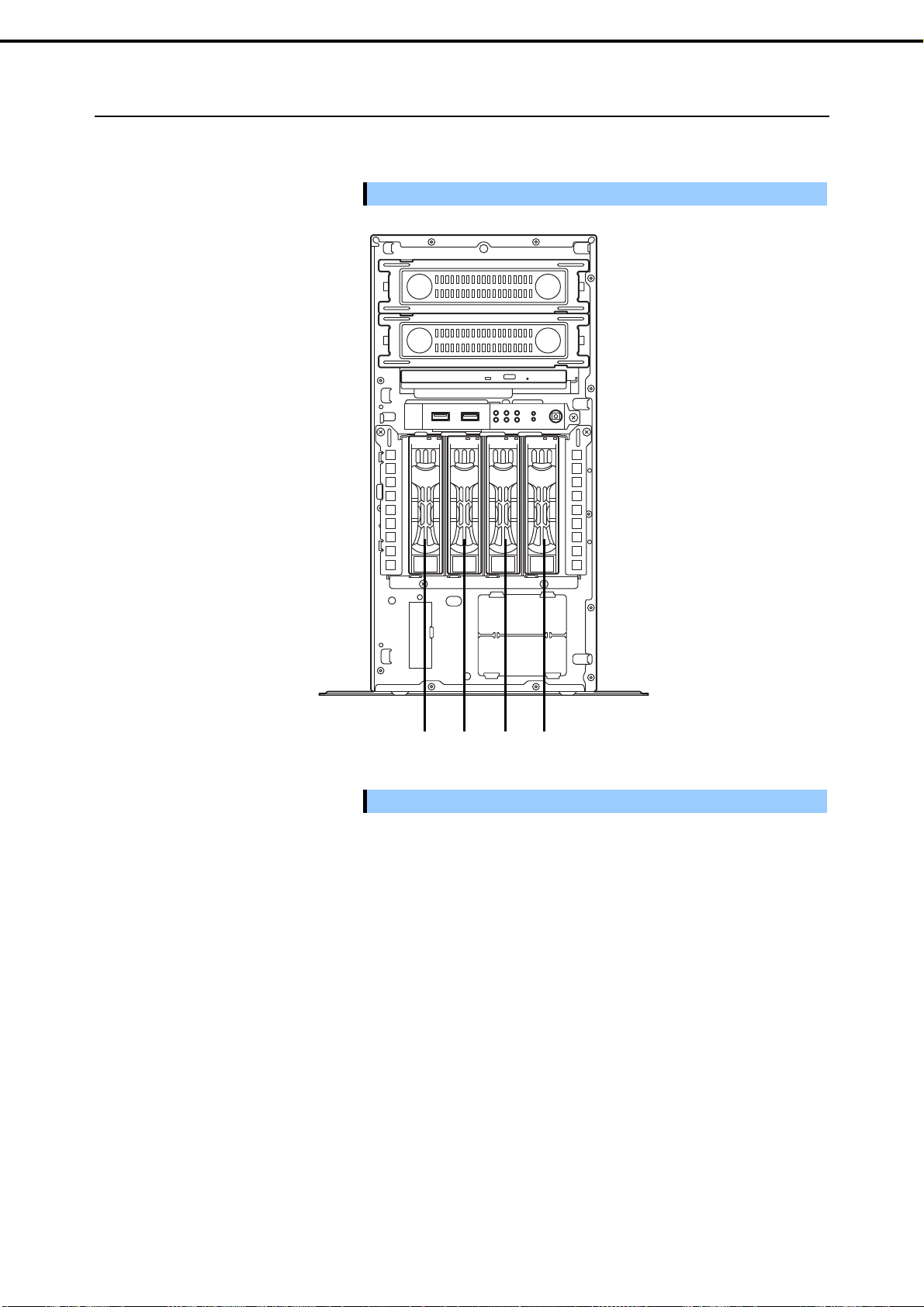
Chapter 2 Preparations
1. Installing Internal Optional Devices
1.11.4
Installing the 3.5-inch HDD cage and hard disk drives
By installing a 3.5-inch HDD cage, up to four 3.5-inch SATA fixed hard disk drives can be mounted.
Important
Use hard disk drives provided by NEC.
Important
Install the hard disk drives sequentially starting from slot 0.
1230
Express5800/T110i User’s Guide
65
Page 66

Chapter 2 Preparations
Install a 3.5-inch HDD cage and hard disk drives in the server by using the following procedure.
1. See steps 1 to 3 in Chapter 2 (1.2 Overview of Installation and Removal) for preparations.
2. To remove the side cover and front bezel, see Chapter 2 (1.3 Removing the Side Cover and 1.4
Removing the Front Bezel).
3. Insert the HDD cage into the HDD bay. The "TOP"
must face rightward.
1. Installing Internal Optional Devices
The "TOP"
must face
rightward.
4. Attach the HDD cage by using the four screws.
5. Connect the interface cables and power cable to the backplane board installed in the HDD cage.
Use the interface cables that come with the HDD cage. For details about cable connection, see
1.15 Connecting Cables.
6. Reassemble the server.
7. Remove the dummy tray from the HDD cage.
66
Important
Keep the dummy trays for future use.
Keep the dummy trays installed in slots where hard disk drives are not
installed.
Express5800/T110i User’s Guide
Page 67

Chapter 2 Preparations
8. Unlock the handle in the tray for a hard disk drive.
9. Hold the tray firmly and insert it in the slot.
1. Installing Internal Optional Devices
Note
Push it all the way until the handle’s lock touches the frame.
Hold the drive carrier firmly with both hands.
10. Gently close the handle until it clicks, indicating that it
is locked.
Note
When you push the drive into the slot, confirm the handle got hooked on the frame.
Express5800/T110i User’s Guide
67
Page 68

Chapter 2 Preparations
1. Installing Internal Optional Devices
1.11.5
Removing the 3.5-inch hard disk drives
Remove the 3.5-inch hard disk drives from the HDD cage by using the following procedure.
Important
When disposing of the hard disk drives, follow the instructions described in
Chapter 1 (1.5 Transfer, movement, and disposal) in Safety Precautions and
Regulatory Notices.
Note
If you remove a disk due to a hard disk drive failure, check the slot with its DISK
LED lit in amber.
1.
To remove the front bezel, see Chapter 2 (1.4 Removing the Front Bezel).
Release the lock lever and open the handle.
2.
DISK LED
3.
Hold the tray firmly and pull it toward the front.
Note
Do not pull the handle to remove the hard disk drive.
Doing so may damage the handle.
Important
Do not use this server while removing the hard disk drive.
68
Express5800/T110i User’s Guide
Page 69

Chapter 2 Preparations
1. Installing Internal Optional Devices
1.11.6
Removing the 3.5-inch HDD cage
Remove the 3.5-inch HDD cage from the server by using the following procedure.
See steps 1 to 3 in Chapter 2 (1.2 Overview of Installation and Removal) for preparations.
1.
To remove the side cover and front bezel, see Chapter 2 (1.3 Removing the Side Cover and 1.4
2.
Removing the Front Bezel).
3.
To remove the hard disk drives installed in the HDD cage, see Chapter 2 (1.11.5 Removing the
3.5-inch hard disk drives).
4.
Disconnect the interface cable and power cable from the backplane installed in the HDD cage.
Disconnect the interface cable from the motherboard or RAID controller.
5.
Remove four screws that attach the HDD cage.
6.
Remove the HDD cage from the server.
7.
Express5800/T110i User’s Guide
69
Page 70

Chapter 2 Preparations
1. Installing Internal Optional Devices
1.11.7
Installing the 2.5-inch HDD cage and hard disk drives
By installing a 2.5-inch HDD cage, up to eight 2.5-inch SAS/SATA hard disk drives or solid state drives (SSD)
can be mounted.
Combining SATA/SAS hard disk drives and SSDs
An optional RAID controller is required to use SAS hard disk drives together with SSDs.
An optional RAID controller is required to install five or more hard disk drives.
You cannot mix them within the same RAID array.
You cannot use SAS hard disk drives that have different rotation speeds within the same RAID array.
Mount SATA/SAS hard disk drives in order from slot 0, and mount the SSDs to the remaining slots.
Important
Use hard disk drives provided by NEC.
70
Important
0 1 2 3 4 5 6 7
Install the hard disk drives sequentially starting from slot 0.
Express5800/T110i User’s Guide
Page 71

Chapter 2 Preparations
Install a 2.5-inch HDD cage and hard disk drives in the server by using the following procedure.
1. See steps 1 to 3 in Chapter 2 (1.2 Overview of Installation and Removal) for preparations.
2. To remove the side cover and front bezel, see Chapter 2 (1.3 Removing the Side Cover and 1.4
Removing the Front Bezel).
3. Insert the HDD cage into the HDD bay. The "TOP"
must face rightward.
1. Installing Internal Optional Devices
The "TOP"
must face
rightward.
4. Attach the HDD cage by using the four screws.
5. Connect the interface cables and power cable to the backplane board installed in the HDD cage.
Use the interface cables that come with the HDD cage. For details about cable connection, see
1.15 Connecting Cables.
6. Reassemble the server.
7. Remove the dummy tray from the HDD cage.
Important
Keep the dummy trays for future use.
Keep the dummy trays installed in slots where hard disk drives are not
installed.
Express5800/T110i User’s Guide
71
Page 72

Chapter 2 Preparations
8. Unlock the handle in the tray for a hard disk drive.
1. Installing Internal Optional Devices
9. Hold the tray firmly and insert it in the slot.
Note
Push it all the way until the handle’s lock touches the frame.
Hold the drive carrier firmly with both hands.
10. Gently close the handle until it clicks, indicating that it
is locked.
Note
72
When you push the drive into the slot, confirm the handle got hooked on the frame.
Express5800/T110i User’s Guide
Page 73

Chapter 2 Preparations
1. Installing Internal Optional Devices
1.11.8
Removing the 2.5-inch hard disk drives
Remove the 2.5-inch hard disk drives from the HDD cage by using the following procedure.
Important
When disposing of the hard disk drives, follow the instructions described in
Chapter 1 (1.5 Transfer, movement, and disposal) in Safety Precautions and
Regulatory Notices.
Note
If you remove a disk due to a hard disk drive failure, check the slot with its DISK
LED lit in amber.
1.
To remove the front bezel, see Chapter 2 (1.4 Removing the Front Bezel).
Release the lock lever and open the handle.
2.
DISK LED
Hold the tray firmly and pull it toward the front.
3.
Note
Do not pull the handle to remove the hard disk drive.
Doing so may damage the handle.
Important
Do not use this server while removing the hard disk drive.
Express5800/T110i User’s Guide
73
Page 74

Chapter 2 Preparations
1. Installing Internal Optional Devices
1.11.9
Removing the 2.5-inch HDD cage
Remove the 2.5-inch HDD cage from the server by using the following procedure.
See steps 1 to 3 in Chapter 2 (1.2 Overview of Installation and Removal) for preparations.
1.
To remove the side cover and front bezel, see Chapter 2 (1.3 Removing the Side Cover and 1.4
2.
Removing the Front Bezel).
3.
To remove the hard disk drives installed in the HDD cage, see Chapter 2 (1.11.8 Removing the
2.5-inch hard disk drives).
Disconnect the interface cable and power cable from the backplane installed in the HDD cage.
4.
Disconnect the interface cable from the motherboard or RAID controller.
5.
Remove four screws that attach the HDD cage.
6.
7.
Remove the HDD cage from the server.
74
Express5800/T110i User’s Guide
Page 75

Chapter 2 Preparations
1. Installing Internal Optional Devices
1.12
1.12.1
Replacing drives
Optical Disk Drive
Procedures for replacing the standard optical disk drive with the optional internal DVD SuperMULTI drive are
described below.
Important Do not install a drive manufactured by a third party.
Follow the procedure below to replace your drive with the optional internal DVD SuperMULTI drive.
1. See Chapter 2 (1.2 Overview of Installation and Removal) for preparations.
2. To remove the side cover and front bezel, see Chapter 2 (1.3 Removing the Side Cover and 1.4
Removing the Front Bezel).
3. Remove the duct. If a device is installed in the 5.25-inch expansion bay 1, remove it so that you can
access the cable connected to the optical disk drive.
4. Disconnect the SATA cable and DC power cable
from the optical disk drive.
5. Push the stopper on the right side and remove the
optical disk drive.
6. Remove the bracket from the optical disk drive.
7. Mount the bracket for the optical disk drive on the DVD SuperMULTI drive.
8. Install the bracket with DVD SuperMULTI drive installed to the server.
9. Connect the SATA cable and DC power cable you disconnected in step 4 to the server.
1.12.2
This completes the installation procedures.
Removal
You can remove the optical disk drive by reversing the installation procedure.
Express5800/T110i User’s Guide
75
Page 76

Chapter 2 Preparations
1. Installing Internal Optional Devices
1.13
Backup Devices
The 5.25-inch expansion bay of the server can contain a backup device such as a magnetic tape drive.
5.25-inch
expansion bay 2
5.25-inch
expansion bay 1
1.13.1
Installation
Install a backup device by using the following procedure.
1. See Chapter 2 (1.2 Overview of Installation and Removal) for preparations.
2. To remove the side cover and front bezel, see Chapter 2 (1.3 Removing the Side Cover and 1.4
Removing the Front Bezel).
3. Remove the blank cover from the front bezel and
the server.
4. Secure the backup device on the left and right sides
by using the four screws that come with the server.
76
Important Use screws supplied with this server to attach the backup device to the tray.
Express5800/T110i User’s Guide
Page 77

Chapter 2 Preparations
5. Insert the backup device into chassis.
Do not push the backup device in completely as
the cable has to be connected to the device.
6. Connect the interface cable and power cable to the installed 3.5-inch backup device.
For more information, see Chapter 2 (1.15 Connecting Cables).
7. Push the device all the way until it clicks, indicating that it is locked.
8. Assemble the server.
9. Install device drivers for installed backup device as needed.
Note
1. Installing Internal Optional Devices
Arrange the unused power supply cable at the rear of the backup device so that
this cable comes between the HDD cage and optical disk drive. Be careful not to
apply a force to the I/F cable connector when pushing in the backup device.
1.13.2
For more information, refer to the manual provided with the backup device.
Removal
You can remove the backup device by reversing the installation procedure. If the devices are to remain
removed, attach the stored dummy cover.
Express5800/T110i User’s Guide
77
Page 78

Chapter 2 Preparations
1. Installing Internal Optional Devices
1.14
Supporting High-temperature Environment
The high-temperature environment setting of this server enables you to use this server under the environment of
5°C to 48°C.
For the high-temperature environment setting, the following configuration is required.
• SDR is the dedicated setting.
• When the non-redundant power supply unit is installed, N8181-132F or N8181-178 Power Supply Fan
required.
• The backup device is not available.
*1 Power Supply Fan type depends on the power supply type.
To make a high-temperature environment, change the jumper switch on motherboard as shown below.
J_MODEL2
*1
is
3 2 1 3 2 1
Disable
Motherboard
Enable
78
Express5800/T110i User’s Guide
Page 79

Chapter 2 Preparations
1. Installing Internal Optional Devices
1.15
1.15.1
Connecting Cables
This section shows an example of internal device cable connection.
Internal interface cables
This section describes the connection of internal interface cables.
Tips
(1) Connecting hard disk drives
This section describes how to connect additional hard disk drives.
(a) Using 3.5-inch fixed hard disk drives
Connect the cables as shown in the following figure. Install the hard disk drives in order from the left side.
The figure shown here primarily describes connections. For more information
about the connectors on the motherboard, see Chapter 1 (4.4 Motherboard).
Connecting to the miniSAS connector on the motherboard
Power
supply
0
1
2
3
Motherboard
HDD cage
MINISAS_1
miniSAS cable
You can use the controller on the motherboard to build a RAID system. For more information, see Chapter 2
(5. RAID System Configuration) in "Maintenance Guide".
Express5800/T110i User’s Guide
79
Page 80

Chapter 2 Preparations
r
Adding a RAID controller (N8103-176/177/178/188)
Power
supply
Motherboard
0-3
RAID controller
* N8103-180 cannot be installed to N8103-188.
1. Installing Internal Optional Devices
0
1
2
3
HDD cage
HDD_LED1
Flash
Backup
Unit
miniSAS cable
Flash back up unit control cable (only when the RAID controller is N8103-176/177/178)
LED cable
Tips
The dedicated cable K410-293(00) is required for installing the RAID controller
(N8103-176/177/178/188) in the server.
About RAID LED cables
The Global HDD LED on the front of the equipment shows the access status of hard disk drives that are
connected to a RAID controller. To display this status, connect the LED cable that comes with the optional
cable K410-293(00).
Connect the LED connector on the motherboard to the connector on the RAID controller.
See the figures below and connect the LED cable to the LED connector of the motherboard.
Motherboard
LED connecto
To the motherboard side
80
Express5800/T110i User’s Guide
Page 81

Chapter 2 Preparations
1. Installing Internal Optional Devices
RAID Controller N8103-176/177/178
RAID Controller N8103-188
Black
Red
Black
Red
Adding a RAID controller (N8103-205/206/207/208/210/211)
Power
supply
0
1
2
3
Motherboard
HDD_LED1
Flash
Backup
Unit
RAID controller
0-3
miniSAS
Flash back up unit control cable (only when the RAID controller is N8103-206/207/208)
LED cable
cable
* N8103-209 cannot be installed to N8103-205/210/211.
Tips
The dedicated cable K410-444(00) is required for installing the RAID controller
(N8103-205/206/207/208/210/211) in the server.
HDD cage
Express5800/T110i User’s Guide
81
Page 82

Chapter 2 Preparations
r
About RAID LED cables
The Global HDD LED on the front of the equipment shows the access status of hard disk drives that are
connected to a RAID controller. To display this status, connect the LED cable that comes with the optional
cable K410-444(00).
Connect the LED connector on the motherboard to the connector on the RAID controller.
See the figures below and connect the LED cable to the LED connector of the motherboard.
Motherboard
1. Installing Internal Optional Devices
To the motherboard side
LED connecto
RAID Controller N8103-206/207/208/210/211
Black
Red
RAID Controller N8103-205
Black
Red
82
Express5800/T110i User’s Guide
Page 83

Chapter 2 Preparations
p
(
(b) Using 3.5-inch HDD cage
Connect the cables as shown in the following figure. Install the hard disk drives in order from the left side.
Connecting to the miniSAS connector on the motherboard
Power
supply
Motherboard
MINISAS_1
BPB_CON1
1. Installing Internal Optional Devices
HDD cage
BPB_CON
MINISAS_1
miniSAS cable
HDD back
lane interface cable
You can use the controller on the motherboard to build a RAID system. For more information, see Chapter 2
(5. RAID System Configuration) in "Maintenance Guide".
Adding a RAID controller (N8103-176/177/178/188)
Power
supply
MINISAS_1
HDD cage
BPB_CON1
BPB_CON
0-3
RAID controller
Flash Backup Unit
N8103-180)
miniSAS cable
HDD backplane interface cable
FBU cable
* N8103-180 cannot be installed to N8103-188.
Express5800/T110i User’s Guide
83
Page 84

Chapter 2 Preparations
(
Adding a RAID controller (N8103-205/206/207/208/210/211)
Power
supply
1. Installing Internal Optional Devices
HDD cage
0-3
RAID controller
BPB_CON
MINISAS_1
BPB_CON1
Flash Backup Unit
N8103-209)
miniSAS cable
HDD backplane interface cable
FBU cable
* N8103-209 cannot be installed to N8103-205/210/211.
(c) Using 2.5-inch HDD cage
Connect the cables as shown in the following figure. Install the hard disk drives in order from the left side.
Connecting one to four hard disk drives to the miniSAS connector on the motherboard
Power
supply
MINISAS_1
Motherboard
HDD cage
BPB_CON1
BPB_CON
MINISAS_1
miniSAS cable
HDD backplane interface cable
You can use the controller on the motherboard to build a RAID system. For more information, see Chapter 2
(5. RAID System Configuration) in "Maintenance Guide".
84
Express5800/T110i User’s Guide
Page 85

Chapter 2 Preparations
Adding one to eight hard disk drives with a RAID controller (N8103-176/177/178/188)
An optional SAS/SATA cable (K410-340(00)) is required when installing five or more hard disk drives.
Power
supply
1. Installing Internal Optional Devices
MINISAS_2
MINISAS_1
Motherboard
HDD cage
BPB_CON1
Flash Backup Unit
(N8103-180)
4-7
BPB_CON
0-3
RAID controller
miniSAS cable
HDD backplane interface cable
FBU cable
* N8103-180 cannot be installed to N8103-188.
Adding one to eight hard disk drives with a RAID controller (N8103-205/206/207/208/210/211).
An optional SAS/SATA cable (K410-340(00)) is required when installing five or more hard disk drives.
Power
supply
MINISAS_2
MINISAS_1
Motherboard
BPB_CON1
BPB_CON
4-7
0-3
RAID controller
miniSAS cable
HDD backplane interface cable
FBU cable
* N8103-209 cannot be installed to N8103-205/210/211.
HDD cage
Flash Backup Unit
(N8103-209)
Express5800/T110i User’s Guide
85
Page 86

Chapter 2 Preparations
(2) Connecting backup devices
The 5.25-inch expansion bay of the server can mount USB devices for internal connection.
(a) Mounting an internal USB device
Use the dedicated internal USB cable (K410-276(00)).
1. Installing Internal Optional Devices
Power
supply
Backup devices
Optical disk drive
Motherboard
SATA4
USB_A1
USB cable
SATA cable
(b) Mounting a SAS device
Use the dedicated internal SAS cable (K410-217(00)).
Power
supply
Motherboard
SATA4
SAS controller
SAS cable
SATA cable
Backup devices
Optical disk drive
86
Express5800/T110i User’s Guide
Page 87

Chapter 2 Preparations
(3) Connecting Dual M.2 SATA mount kit (N8118-307)
The server can mount dual M.2 SATA mount kit (N811-307) on PCI slot. The dual M.2 SATA mount kit has 2
slot that can mount 120GB M.2 SATA SSD(N8150-736).
(a) When SSD is used in software RAID
Use the dedicated internal SAS/SATA cable (K410-365(00)) and connecting to the miniSAS connector on
the motherboard.
1. Installing Internal Optional Devices
Express5800/T110i User’s Guide
87
Page 88

Chapter 2 Preparations
(b) When SSD is used in hardware RAID
Use the dedicated internal SAS/SATA cable (K410-365(00)) and connecting to the RAID controller.
1. Installing Internal Optional Devices
RAID LED cable (K410-293(00)): When using the RAID controller (N8103-176/177/188)
RAID LED cable (K410-444(00)): When using the RAID controller (N8103-205/206/210)
Note
M.2 SATA SSD and hard disc drive cannot be connected to the same RAID
controller.
88
Express5800/T110i User’s Guide
Page 89

Chapter 2 Preparations
1. Installing Internal Optional Devices
1.15.2
Power cables
The figure below shows an example of connecting the power cables. Power cables other than those shown
here are not used by the devices.
(1) Non-Redundant Power Supply Model (EXP334)
(a) Using 3.5-inch fixed HDD cage
Power
supply
PWR_DET1
P2
Motherboard
P1
P9
P11
P4
P5
P6
P12
P14
P15
3
2
1
0
Backup devices
Optical disk drive
HDD cage
Power convert cable
Cable connected to power supply
Unused power supply cable connector
(b) Using 3.5-inch HDD cage
Power
supply
PWR_DET1
P2
Motherboard
P12 P15
P1
P6
CN1
CN2
P4
P5
P8
P9
Backup devices
Optical disk drive
HDD cage
Power convert cable
Cable connected to power supply
Unused power supply cable connector
Express5800/T110i User’s Guide
89
Page 90

Chapter 2 Preparations
(c) Using 2.5-inch HDD cage
1. Installing Internal Optional Devices
Power
supply
P12 P15
P6
PWR_DET1
P2
P1
Motherboard
Cable connected to power supply
Unused power supply cable connector
CN1
P8
CN2
P9
P5
P4
Backup devices
Optical disk drive
HDD cage
Power convert cable
90
Express5800/T110i User’s Guide
Page 91

Chapter 2 Preparations
(2) Redundant Power Supply Model (EXP334A)
(a) Using 3.5-inch fixed HDD cage
Power
supply
5.2Dev2
5.2Dev1
ODD
1. Installing Internal Optional Devices
Backup devices
Optical disk drive
PWR_DET1
P2
Motherboard
Cable connected to power supply backplane
DC cable
Unused power supply cable connector
(b) Using 3.5-inch HDD cage
Power
supply
P3
HDD cage
P1
3
2
1
0
5.2Dev2
5.2Dev1
ODD
Backup devices
Optical disk drive
HDDBP1
PWR_DET1
P2
P3
HDDBP2
P1
Motherboard
Cable connected to power supply backplane
DC cable
Unused power supply cable connector
CN1
CN2
HDD cage
Express5800/T110i User’s Guide
91
Page 92

Chapter 2 Preparations
(c) Using 2.5-inch HDD cage
Power
supply
5.2Dev2
5.2Dev1
ODD
1. Installing Internal Optional Devices
Backup devices
Optical disk drive
PWR_DET1
P2
P3
HDDBP1
P1
CN1
CN2
Motherboard
Cable connected to power supply backplane
DC cable
Unused power supply cable connector
HDD cage
HDDBP2
92
Express5800/T110i User’s Guide
Page 93

Chapter 2 Preparations
1. Installing Internal Optional Devices
1.16
Attaching the Front Bezel
You can attach the front bezel by reversing the removal procedure. Attach the front bezel to the server by
inserting the three tabs on the inside of the front bezel into the slits on the right-front of the server and then
pressing the left side of the front bezel to secure it into place on the front of the server.
Insert tabs inside the
bezel into the slit on the
chassis.
Express5800/T110i User’s Guide
93
Page 94

Chapter 2 Preparations
1. Installing Internal Optional Devices
1.17
Installing the Side Cover
You can attach the side cover by reversing the removal procedure.
Make sure that hooks at both the top and bottom of the side cover are securely inserted in the slits on the
server frame. Also make sure that the hooks at the front of the cover are engaged with the server frame when
sliding the side cover forward to attach. If they are not engaged with the frame, the cover cannot be secured in
place.
94
Express5800/T110i User’s Guide
Page 95

Chapter 2 Preparations
A
y
k
2. Installation and Connection
2.
Installation and Connection
This section describes how to position the server and connect cables.
2.1
Installation
Be sure to observe the following precautions to use the server safety. Failure to
observe the precautions may cause death or serious injury. For details, refer to
Safety Precautions and Regulatory Notices.
Use only in the specified environment.
Do not connect the ground wire to a gas pipe.
WARNING
CAUTION
Be sure to observe the following precautions to use of the server safely. Failure
to observe the precautions may cause burns, injury, and property damage. For
details, refer to Safety Precautions and Regulatory Notices..
Do not attempt to lift the server by gripping the front bezel.
Do not carry or install the server only by a single person.
Install and store only in the specified environment.
The environment suitable for the server is as follows.
Hold the server firmly, and slowly and gently place it in the position in which it is to be installed.
At least 150 mm clearance in
front of/behind the server
Cables for the mouse or other
The environment that satisfies the
following conditions:
<Operating>
Ambient temperature:5°C to 40°C*1
Humidity: 10% to 85% *2
Temperature gradient: ±10°C/hour
Air pressure: 749 to 1040 hpa
<Non-operation>
Ambient temperature:5°C to 40°C*1
Humidity: 10% to 85% *2
Temperature gradient: ±15°C/hour
Air pressure: 749 to 1040 hpa
devices are within easy reach
On a flat and
des
sturd
*1: 5°C to 48°C (when an optional
kit is installed; subject to
composition restrictions)
*2: 10% to 80% (when internal
LTO is installed)
100/200VAC bipolar grounded
outlet or bipolar outlet with
ground terminal (separate
adapter is required)
Express5800/T110i User’s Guide
Dust-free, clean, and
organized room
95
Page 96

Chapter 2 Preparations
r
r
Do not install the server in an environment in which any of the following conditions apply: Installing the server
in any of the following conditions will cause the server to malfunction.
Place of drastic temperature change,
near a heater, air conditioner, or
refrigerator.
Place where intense vibration may be
generated.
2. Installation and Connection
Places where corrosive gas is present,
such as environments where there is
sulfur vapor in the atmosphere, o
places where chemicals are nearby o
may be accidentally sprayed over.
Place where a carpet not subject to
anti-static process is laid.
Place where the power cord of the
server must be connected to an AC
outlet that shares the ground wire with
another outlet where another device
with large power consumption is
connected.
Place where some objects may be
fallen.
Place near a device generating intense
magnetic field such as TVs, radios,
broadcast/communication antennas,
power transmission wires, and
electromagnetic cranes is placed.
Places where the power cords or
interface cables may be stepped on or
tripped over.
Do not install where there is power
supply noise nearby such as contact
sparks when turning power on or off
during power relays. If you must install
the server close to such equipment,
separate power cables or install noise
filter.
96
Express5800/T110i User’s Guide
Page 97

Chapter 2 Preparations
A
2.1.1
Preparation for installation
Remove the stabilizer attached to the bottom of the server, and then change as instructed below.
Removing/installing the stabilizer
Removing the stabilizer
Remove the two screws from the stabilizer to remove the stabilizer from the server.
2. Installation and Connection
Installing the stabilizer
Turn the stabilizer 90 degree as shown in the figure below, and then fix it by using the two screws.
fter attaching the stabilizers, set up the server as
shown in the image.
Express5800/T110i User’s Guide
97
Page 98

Chapter 2 Preparations
2. Installation and Connection
2.2
Connection
Connect peripheral devices to the server. Connectors that enable a variety of peripheral devices to be
connected are provided at the front and rear of the server. Figures on the following pages show the peripheral
devices that can be connected as standard. Connect the peripheral devices before connecting the power cord
to the server.
Be sure to observe the following precautions to use the server safety. Failure to
observe the precautions may cause death or serious injury. For details, refer to
Safety Precautions and Regulatory Notices.
Do not hold the power plug with wet hands.
WARNING
Be sure to observe the following precautions to use of the server safely. Failure
to observe the precautions may cause burns, injury, and property damage. For
details, refer to Safety Precautions and Regulatory Notices.
Use only the specified outlet to insert.
Do not connect the power cord to an outlet that has an illegal number of
connections.
Insert the power plug into the outlet as far as it goes.
Use only the specified power cord.
Do not connect or disconnect the interface cable while the power cord is
connected.
Use only the specified interface cable.
CAUTION
98
Express5800/T110i User’s Guide
Page 99

Chapter 2 Preparations
2.2.1
Interface cables
Connect the interface cable before connecting the power cord.
2. Installation and Connection
Important
Turn off the server and peripheral devices to be connected before
connecting.
If you use the third party display or peripheral devices, and connect the
interface cable, contact the dealer to check whether they can be used.
Direct connection from the standard serial port of this sever to the
dedicated network line is disabled. To connect to the dedicated line, be
sure to connect from the terminal device approved by the
Telecommunications Business Act (the dedicated line means the dedicated
transmission path installed by the specified users and its accessories.
Generally-used public line is also included.)
The connectors that are not explained here are not available. Do not
connect anything to the connectors.
Express5800/T110i User’s Guide
99
Page 100

Chapter 2 Preparations
2. Installation and Connection
<Front view>
USB devices
A device with serial
face
inter
(such as a modem)
Display unit
USB devices (such as a
terminal adapter)
<Rear view>
Connect the provided
er cord to an outlet
pow
when the cable
connection is complete.
Hub/Switching hub
100
Express5800/T110i User’s Guide
 Loading...