

Page 1
PREVENTIVE MAINTENANCE ROI-S05751
Chart 4-2 (Cont’d)
Step Procedure
9 Click on “RMON(Line)(7days/day)” sub-menu button in
“PMON (History)”,
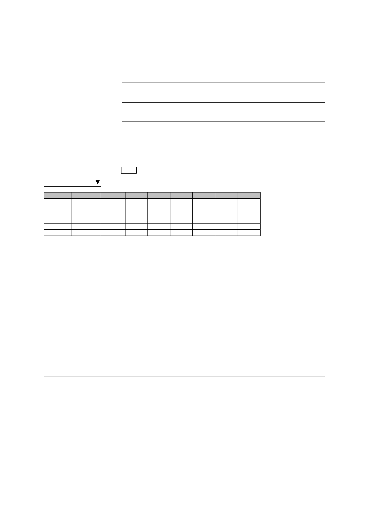
---RMON(Line)(1day)--- Maintenance Mode: on
Port1
Date Time Status 1 2 3 4 5 6
Detailed daily Line (LAN) RMON (Remote Network Monitoring) data are
displayed.
Note: For the GbE INTFC, there are distinctions for the
functions from the 10BASE-T/100BASE-Tx, refer to Notes
of above “RMON(Line)(24H/15min)”.
1:
RX UNICAST
2:
RX BROADCAST
3:
RX MULTICAST
4:
RX PAUSE
5:
RX CEC ERR
6:
RX ALIGNMENT ERR
7:
RX SYMBOL ERR
8:
RX UNDERSIZE
9:
RX FRAGMENTS
10:
RX 64
11:
RX 65-127
12:
RX 128-255
13:
RX 256-511
14:
RX 512-1023
15:
RX 1024-1536
16:
RX 1537-MAX
17:
RX JABBERS
18:
TX UNICAST
19:
TX BROADCAST
20:
TX MULTICAST
21:
TX PAUSE
22:
TX COLLISION
4-12
12 pages
Page 2

ROI-S05751 CORRECTIVE MAINTENANCE
5. CORRECTIVE MAINTENANCE
Corrective maintenance done in the field is described in this chapter.
Corrective maintenance in the field covers fault isolation, module/unit
replacement and alignment. The fault location procedures describes how
to isolate module-level/unit-level faults.
Faults can be classified into those that cause deterioration of the
transmission quality and those that interrupt the traffic due to a
malfunction of the equipment. This chapter explains the troubleshooting
procedures for equipment faults and the corresponding remedial methods.
The purpose of troubleshooting malfunctioning equipment is to restart the
service by locating the faulty part and replacing it with a spare.
The faults that cause deterioration in the transmission quality are primarily
originated by changes occurred in the state of propagation. Therefore, if a
decline in the transmission quality or similar fault takes place frequently,
the link design will have to be reviewed.
5.1 Alarm/Status
During the corrective maintenance, carefully observe the precautions
given in Chapter 2, until the alignment is completed.
When an alarm event has occurred, At first, check alarm indication on the
front of the IDU. Continuously, connect the PC to the LCT jack on the
IDU and check alarm/status indication, Meter Reading on the LCT.
(a) Check of the ALM LED Indications and LCT Indication
A faulty part can be located by checking the ALM LED indicators
and LCT Alarm indications. For the explanation of the ALM LED
indication, refer to Chapter 2 OPERATING EQUIPMENT in
Section II. Also refer to Chapter 2 Alarm/Status in this Section IV
APPENDIX LCT OPERATION.
(b) Meter Readings
Based on the meter readings during periodical inspection with
LCT described in Chapter 4, a faulty part can be located by
checking if the reading values exceed the permissible ranges.
(c) Loopback
In the case of an abnormal BER measurement result among the
meter reading items, try to distinguish the faulty part by Chart
5.1.1 Loopback.
5-1
Page 3

CORRECTIVE MAINTENANCE ROI-S05751
5.1.1 Alarm and Status
The alarm and status of each module and ODU are displayed.
Each items is explained below.
ODU
TX Power: Indicates the status of the transmitter in the ODU.
When the transmission level is decreased 3 dB or
more from preset ATPC minimum level, “Alarm”
is issued.
TX Input: Indicates the status of the ODU input signal from
IDU. When the input signal from the IDU is lost,
“Alarm” is issued.
RX Level: Indicates the status of the received RF signal level
of the ODU. When the level decreased below the
RX threshold level, “Alarm” is issued.
APC: Indicates the status of the synthesizer in the ODU.
When any abnormality occurs in the synthesizer,
“Alarm” is issued.
ODU CPU/Cable Open:
Indicates the status of the CPU in the ODU or IF
cable, When any abnormality occurs the CPU
operation or IF cable is open, “Alarm” issued.
Mute Status: Indicates the control status of the ODU TX power
output. When the TX power is set to Mute, “On”
is issued.
LO REF (for XPIC in SONET):
Indicates the status of reference LO signal used for
V/H signal synchronization. When the reference
signal in the ODU is lost, “Alarm” is issued.
TX SW Status (for 1+1 configuration):
Indicates the TX SW status for the No. 1 or No. 2
CH selection.
RX SW Status (for 1+1 configuration):
Indicates the RX SW status for the No. 1 or No. 2
CH selection.
5-2
Page 4

ROI-S05751 CORRECTIVE MAINTENANCE
MODEM
Unequipped:
Indicates the status of the MODEM existence.
When the MODEM is loose contact or it is not
mounted according to the “Equipment Setup”,
“Alarm” is issued.
Module:
Indicates the status of the modulator-demodulator.
When a failure occurred in the modulatordemodulator and as a result of a LSI failure,
“Alarm” is issued.
LOF: Indicates the frame synchronization status.
When the synchronization from DMR is lost,
“Alarm” is issued,
Frame ID: Indicates the status of ID number against
MODEM of opposite station or the other channel
in Twinpath configuration. When ID number
assignment is improper, “Alarm” is issued.
High BER: Indicates the quality severe deterioration status
between radio sections. When the signal
deteriorates below the threshold preset value,
“Alarm” is issued. The settable threshold values
are: 1E-3, 1E-4 and 1E-5.
Low BER: Indicates the quality unsevere deterioration status
between radio sections. When the signal
deteriorates below the preset threshold value,
“Alarm” is issued. The settable threshold values
are: 1E-6, 1E-7, 1E-8 and 1E-9.
Early Warning:
Indicates quality deterioration status. When the
signal deteriorates below the preset threshold
level, “Alarm” is issued. (When the Early Warning
is used for protection switchover in 1+1
configuration, RX Hitless Switch is operated.) The
preset threshold level is less than 1E-9.
MOD: Indicates the operating status of the MOD. When
any failure occurs in the modulator section,
“Alarm” is issued.
DEM: Indicates the operating status of the DEM. When
any failure occurs in the demodulator section,
“Alarm” is issued.
5-3
Page 5

CORRECTIVE MAINTENANCE ROI-S05751
Input Voltage:
Indicates the power supply input voltage status.
When power supply is exceeding the limited,
“Alarm” is issued.
Power Supply:
Indicates the operating status of the power supply.
When power supply is abnormal, “Alarm” is
issued.
IF Cable Short:
Indicates the status of IF cable between IDU and
ODU. When a short circuit is caused between
ODU and the IDU, “Alarm” is issued.
Cable EQL: Indicates the status of IF cable equalizer. When
equalizer characteristics control is lost, “Alarm” is
issued.
XIF (for XPIC in SONET):
Indicates the status of XIF input signal of the Main
Master IDU and Sub Master IDU. When the XIF
input signal is lost, “Alarm” is issued and XPIC
function is reset.
XPIC Status (for XPIC in SONET):
Indicates the status of XPIC operation. When the
XPIC function is reset, “Reset” is indicated and
the “Reset” LED on the front panel is lit.
XREF (for XPIC in SONET):
Indicates the status of reference CLK signal used
for V/H signal synchronization. When the
reference OSC in the MODEM failure occurs,
“Alarm” is issued.
Linearizer Function:
Indicates the status of linearizer function.
OPR: When the linearizer function is used.
NO OPR:When the linearizer function is not used.
In this case, TX output power decreases
approx. 4 dBm from a standard value.
N/A: When the ODU is used without
linearizer function.
Linearizer: Indicates the linearizer operating status. When
linlearizer operation is improper in OPR condition,
“Alarm” is issued.
5-4
Page 6

ROI-S05751 CORRECTIVE MAINTENANCE
ATP C P o w e r M od e:
Indicates the status of ATPC operation mode.
When the ATPC function is improper, stop the
control and maintain the TX output level at
HOLD/MAX/MIN selectable.
INTFC (Main/Sub)
INTFC(1/2) Module:
Indicates the operating status of the ( ) INTFC.
When any failure occurs in the INTFC(1/2)
Module, “Alarm” is issued.
INTFC(1) Unequipped:
Indicates the existence status of the ( ) INTFC.
When the ( ) INTFC(1) is not equipped, “Alarm”
is issued.
INTFC(2) Unequipped (for SONET):
Indicates the existence status of the ( ) INTFC.
When the ( ) INTFC(2) is not equipped, “Alarm”
is issued.
INTFC(1/2) Type Mismatch:
Indicates the mounted status of the ( ) INTFC.
When the INTFC(1/2) type is not coincided with
the inventory list, “Alarm” is issued.
INTFC(1) In-Phase:
Indicates the received signal DADE status
between No. 1 and No. 2 at STM/( )E1 INTFC.
When the received signal delay time is out of
permissible range, Outphase alarm is issued.
OC-3(1) LOS (MUX) (for SONET):
Indicates the input signal status of the OC-3 from
MUX. When the input is disconnected, “Alarm” is
issued.
OC-3(1) LOF (MUX) (for SONET):
Indicates the input signal status of the OC-3 from
MUX. When the input signal is out of frame
synchronization, “Alarm” is issued.
E-BER(1) (MUX) (for SONET):
Indicates Excessive-BER of the input OC-3 signal
from MUX. When the signal deteriorates below
the preset threshold level, “Alarm” is issued. The
settable threshold values are 1E-3, 1E-4 and 1E-5.
OC-3(1) SD (MUX) (for SONET):
5-5
Page 7

CORRECTIVE MAINTENANCE ROI-S05751
Indicates the input signal status of the OC-3 from
MUX. When the signal deteriorates below the
preset threshold level, “Alarm” is issued. The
settable threshold values are 1E-6, 1E-7, 1E-8 and
1E-9.
OC-3(1) LOS (DMR) (for SONET):
Indicates the signal status of the OC-3 from DMR.
When the input is disconnected, “Alarm” is issued.
5-6
Page 8

ROI-S05751 CORRECTIVE MAINTENANCE
OC-3(1) LOF (DMR) (for SONET):
Indicates the status of the input OC-3 signal from
DMR. When the input signal is out of
synchronization, “Alarm” is issued.
OC-3(1) E-BER (DMR) (for SONET):
Indicates Excessive-BER of the input OC-3 signal
at the Radio side. When the signal deteriorates
below the preset threshold level, “Alarm” is
issued. The setable threshold values are 1E-3, 1E4 and 1E-5.
OC-3(1) SD (DMR) (for SONET):
Indicates the input signal status of the OC-3 from
DMR. When the signal deteriorates below the
preset threshold level, “Alarm” is issued. The
setable threshold values are 1E-6, 1E-7, 1E-8 and
1E-9.
OC-3(1) TF (for SONET):
Indicates the signal interruption status. Indicates
when MS-AIS Generation is set to “Disable”.
When OC-3 output signal of OC-3 INTFC is
stopped, “Under Execution” is indicated.
LAN Link (Port ( )) (LAN INTFC for SONET):
Indicates the status of Link between related
equipment and Port ( ). Indicates “Link” when the
Port is linked with related equipment and indicates
“Alarm” in other case.
LAN Collision (Port ( )) (LAN INTFC for SONET):
Indicates the status of Collision in Half Duplex
mode. In Full Duplex mode, “Normal” is always
displayed. Indicates status when Port ( ) is in
collision condition.
Link Loss Forwarding (LLF) (Port ( )) (LAN INTFC for
SONET):
Indicates the operating status during the fault in
opposite station or when the link of local Port ( )
LAN is disconnected by the fault of radio section.
When any failure occurs in the MAIN INTFC,
“Alarm” is also issued.
Speed & Duplex: (Port ( )) (LAN INTFC for SONET):
Indicates the operating mode of Port ( ).
CTRL
CTRL Module:
Indicates the operating status of the CTRL. When
any failure occurs in the CTRL Module, “Alarm”
5-7
Page 9

CORRECTIVE MAINTENANCE ROI-S05751
is issued.
MMC:
Indicates the MMC status. When the mounted
MMC is detected, “On” is displayed.
APS SW Fail (for APS in SONET):
Indicates the APS status of the APS system. When
the APS switchover failure occurs, “Alarm” is
issued.
APS Online Status (for APS in SONET):
Indicates online channel on the APS system.
XCTRL (for XPIC in SONET):
Indicates the status of control signal between Main
Master IDU and Sub Master IDU. When the out of
control condition occurs, “Alarm” is issued.
XPIC Mode Mismatch (for XPIC in SONET):
Indicates the status of the Main Master IDU and
Sub Master IDU definition. When the Main
Master IDU and Sub Master IDU is not defined
properly as like as Main Master-Main Master or
Sub Master-Sub Master, “Alarm” is issued.
5-8
Page 10

ROI-S05751 CORRECTIVE MAINTENANCE
5.1.2 Control Item
Control items can be selected only under maintenance mode. As this
“Control” is likely to cause disconnection of signal, take care during
operation.
Details of “Control” item is described as follows:
TXSW manual control:
Controls manual switchover of the TX SW at the
transmitting side in the Hot standby (HS)
configuration.
RXSW manual control:
Controls manual switchover of the RX SW in the
1+1 configuration. The switchover is carried out
without traffic interruption when the DADE is Inphase. Adjustment of the delay time of No.1 and
No.2 is automatically set.
Caution: When the RX SW mode is set to “Forced” in
provisioning, RX SW manual control can select
either No. 1 or No. 2 RX route though one is
alarmed. Then, take care switching to avoid traffic
interruption.
ATPC manual control:
Used when it is required ATPC operation ON/OFF
or the change of the transmitting power range in
ATPC operation.
TX mute: Turns off the transmitter output.
CW CONTROL (No.1/2):
Used for transmitting a unmodulated carrier wave
(CW). Used to confirm the TX frequency stability.
APS Manual Control (for APS in SONET):
Controls manual switchover (Auto/Working/
Protection) of the Optical Line in the APS system.
Caution: When the APS Maintenance mode is set to “Forced”
in provisioning, APS Manual Control can select
either Working or Protection line though one is
alarmed. Then, take care switching to avoid traffic
interruption.
IF loopback: Used for distinguish equipment failure to ODU or
IDU. The input traffic signal from MUX is looped
back at IF stage. When no abnormality is found in
the signal after IF loopback, it is assumed that the
ODU has a problem.
5-9
Page 11

CORRECTIVE MAINTENANCE ROI-S05751
Since the control is not interlocked with the RX
SW, the RX SW control is needed to select CH
which it is IF looped back in 1+1 configuration.
Main Loopback (NEAR END) (for SONET)/
Main Loopback (NEAR END) INTFC (1) or (2) (for SONET
APS)/:
Used for distinguish equipment failure to MUX
equipment or radio equipment. The input signal
from MUX is looped back to the MUX. When no
abnormality is found in the signal with NEAR
END loopback, it is assumed that the radio
equipment (IDU or ODU) has a problem.
Main Loopback (FAR END) (for SONET):
Used for distinguish equipment failure to MUX
equipment or radio equipment. Signal is looped
back at the IDU of the opposite station. When no
abnormality is found in the signal through FAR
END loopback, it is assumed that the local radio
equipment (IDU or ODU) has no problem.
Note: This function is unavailable when 2-WAY/XC is
enabled.
DADE Adjust:
Sets the DADE for Hot Standby SD/Twinpath
configuration. Selects to make INTFC status Inphase.
Notes: 1. The DADE control applies in 1+1 configuration to
adjust delay time for RX hitless switching when the
INTFC status is indicated Outphase.
5-10
Page 12

ROI-S05751 CORRECTIVE MAINTENANCE
2. The DADE adjustment is needed in initial lineup or
when the IF CABLE is replaced. It is not needed
readjustment when the INTFC status is indicated Inphase.
LAN Device Reset (for LAN transmission only):
Used for reset control to LAN interface Port 1 or
Port 2.
Linearizer Control:
Sets Auto/Forced Reset of linearizer function.
Forced Reset: When the linearizer function is not used.
Auto: When the linearizer function is used.
RF SUB Band select:
Used for changing the ODU sub band for radio
link depending on the RF frequency assignment.
Antenna Alignment Mode:
The Antenna Alignment Mode is used for
extending the dynamic range of the NLITE E
Monitor unit. In order to measure in high range of
AGC V, it is mandatory required to set Antenna
Alignment Mode to ON. If not it set to ON, the
indicated AGC voltage is not guaranteed value.
For the antenna orientation, set the TX power to
the required level by MTPC mode at the opposite
site.
Note: It is necessary to set to Antenna Alignment Mode when
monitor the RX level with the NLITE E Monitor unit.
ALS Restart (for SONET optical interface):
Sets the duration that the laser is emitted when
ALS manual restart for test is performed.
XPIC Control Local (for XPIC in SONET):
Resets the XPIC function for Local IDU when
propagation is deteriorated, either MODEM or
ODU of Main Master or Sub Master is a failure or
perform the link test.
XPIC Control Remote (for XPIC in SONET):
Resets the XPIC function for the IDU in the
opposite station when either MODEM or ODU of
Main Master or Sub Master in the local station is a
failure or perform the link test.
5-11
Page 13
CORRECTIVE MAINTENANCE ROI-S05751
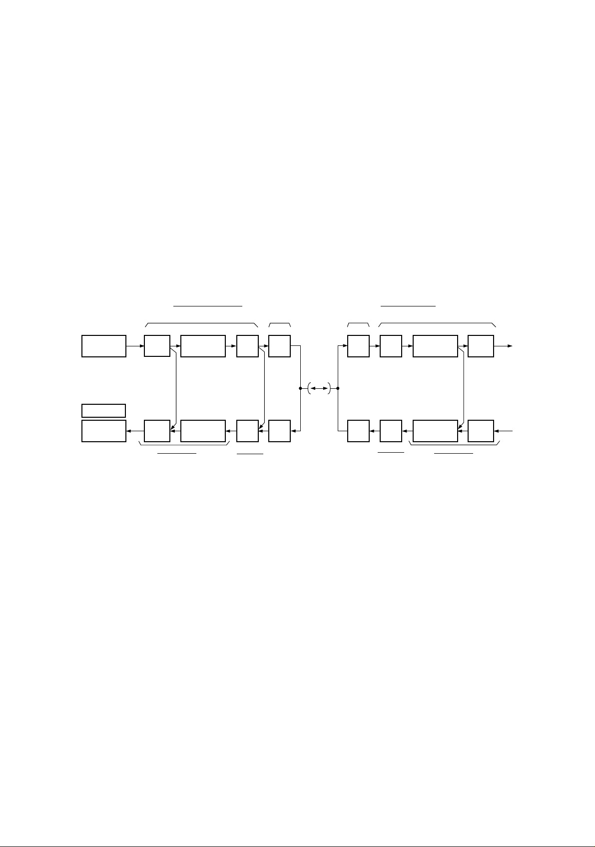
5.1.3 Loopback
When loopback condition is necessary, set the system to loopback
condition. (see Chart 5-1)
STM/SONET
ANALYZER
(Near End Loopback)
PC
STM/SONET
ANALYZER
When there is an interruption of signals, us
analyzers and isolate the faulty section by checking the traffic signal by
loopback. Setup the test equipment according to the following diagrams
for PDH or SONET configuration.
TRANSMITTING END
ODUIDU
C/N
(O/E)
CONV
N/C
(E/O)
CONV
OC-3 INTFC
RST
RST
MOD
(IF Loopback)
DEM
MODEM
TX
RX
Fig. 5-1 Loopback Diagram for Fault Isolation for SONET
RECEIVING END
DEMRX
MODTX
MODEM
e the STM/SONET/PDH
IDUODU
RST
(Far End Loopback)
RST
OC-3 INTFC
N/C
(E/O)
CONV
C/N
(O/E)
CONV
5-12
Note: The IF LOOPBACK and the RX SW is not operated interlock. In
1+1 configuration, The RX SW switching is needed to select the
same CH that is testing in IF LOOPBACK.
When the RX SW manual control is disable, set it to Forced mode
in Provisioning.
Page 14

ROI-S05751 CORRECTIVE MAINTENANCE
Chart 5-1 Loopback Control
Step Procedure
For the LCT operation, refer to Chapter 6 of LCT Operation in
Appendix of this Section IV.
This chart contains:
A. Preparation
B. IF Loopback Control
C. Main Loopback (Near End) Control (SONET)
D. Main Loopback (Far End) Control (SONET)
If loopback operation is performed, timing loop may occur (timing loop is
described in ITU-T Recommendation G.781).
Step Procedure
Caution: The Loopback control affects the radio link connection.
1. Loopback control operation is not performed at the
same time, or perform the Loopback reset control
and perform either Loopback mode.
• IF Loopback
• Near End Loopback
• Far End Loopback
2. Loopback operation is not performed with an
opposite station simultaneously.
3. Far End Loopback control will be canceled when
radio link failure occurs under the control has been
executed.
A. PREPARATION
1 Set up the BER measurement, (refer to Fig. 5-3)
2 Connect the LCT port and the USB port with a USB cable, (see
Fig. 2-2 in Chart 2-2)
3 Login LCT with User name “Admin” and Admin password,
5-13
Page 15
CORRECTIVE MAINTENANCE ROI-S05751
Chart 5-1 (Cont’d)
Step Procedure
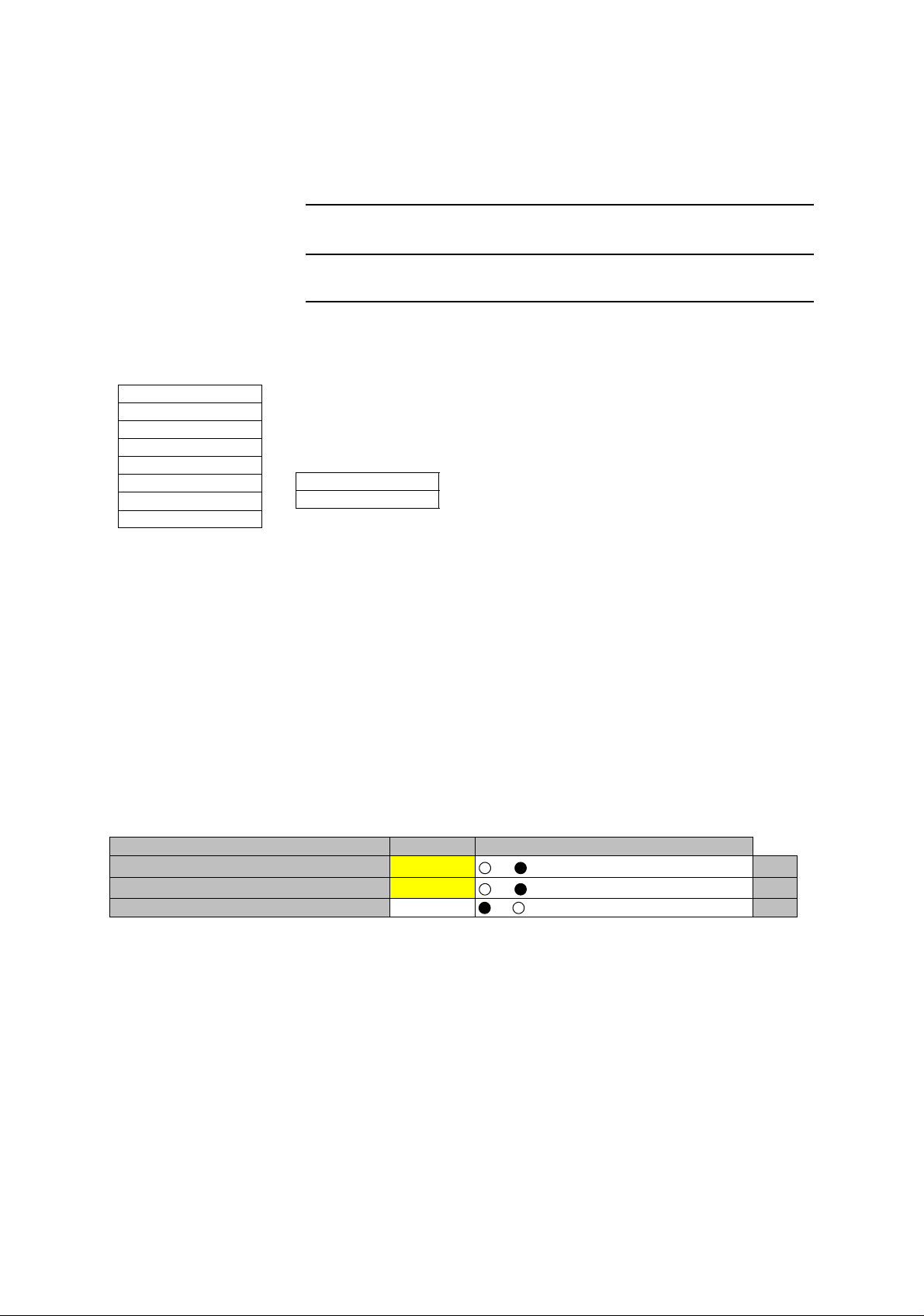
4 Click on the “Maintenance” button in “LCT MENU”,
LCT MENU
Alarm/Status
Equipment Setup
Inventory
AUX I/O
Maintenance
Provisioning
Metering
PMON(History)
Maintenance1
Maintenance2
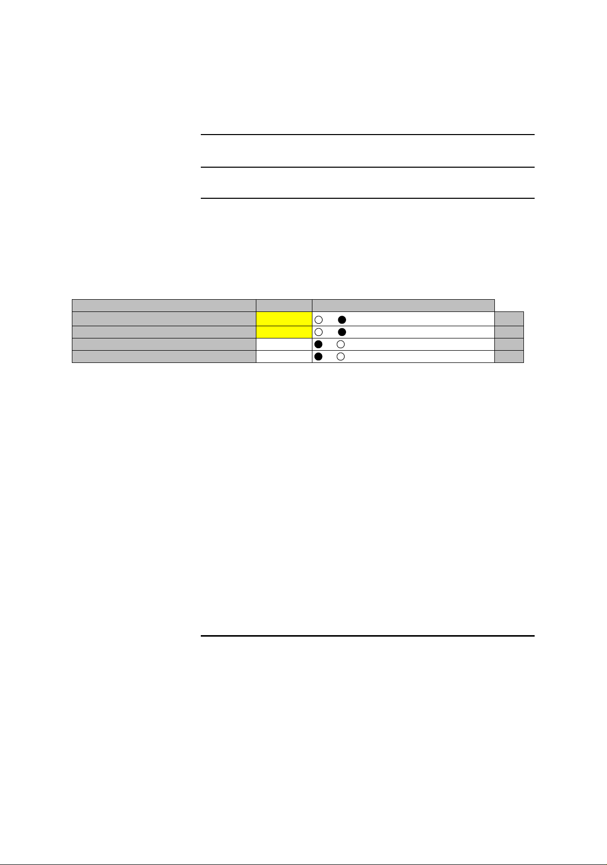
5 Click on the “Maintenance1” menu,
6 Click on the control button “On” and click “S
et” button, to set to
Maintenance On mode,
7 For 1+1 configuration, switchover the TX SW and RX SW for
the channel is to be se
t loopback, (Refer to Chart 2.3 Manual
Switchover Operation)
8 Click on the “IF Loopback ( )” button in “Ma
intenance1” menu
and click on the setting button “On”,
Note: The control affects
Radio link connection.
---Maintenance1---
Item Value Setting
Maintenance On
IF Loopback (No.1) On
IF Loopback (No.2) Off Off On Set
Note:The control applies
Off On
Off On
to IF loopback in local MODEM.
Set
Set
9 Click on the “Set” button,
10 Click on the Alarm/Status on LCT MENU to check the status,
11 Refer to Fig. 5-7 to 5-9 Troubleshooting Flowchart to diagnose
th
e problem,
5-14
12 Click on the setting button “Off” of the IF Loopback ( ) and
click on the “Se
t” button,
Page 16
ROI-S05751 CORRECTIVE MAINTENANCE
Chart 5-1 (Cont’d)
Step Procedure
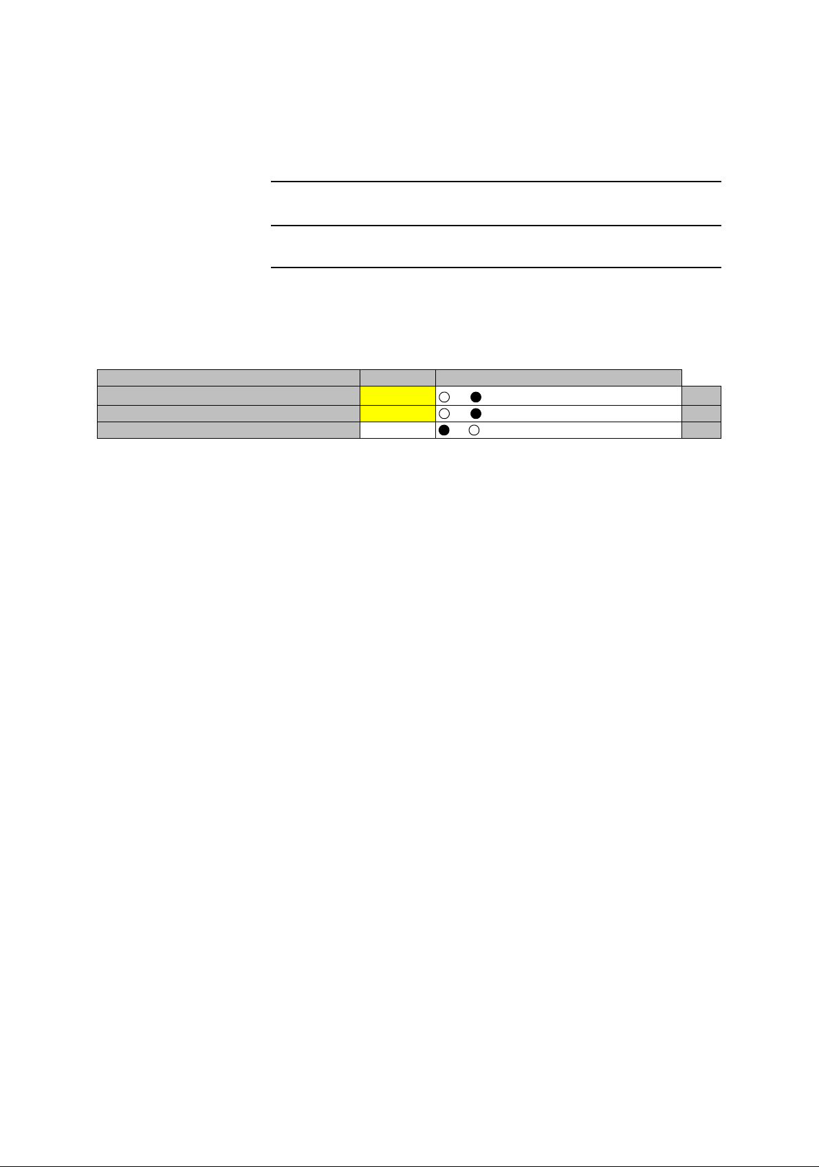
For OC-3 (E)
13 Click on the setting button “On” and click on the “Set” button,
---Maintenance1---
Item Value Setting
Maintenance On
Main Loopback (Near End) On Off On Set
Main Loopback (Far End) Off Off On Set
Off On
Set
5-15
Page 17
CORRECTIVE MAINTENANCE ROI-S05751
Chart 5-1 (Cont’d)
Step Procedure
For OC-3 (O) (APS)
14 Click on the “Main Loopback (Near End)” button in
“Maintenance1” menu, click on the setting button “INTFC ( )” and
click on the “Set” button,
---Maintenance1---
Item Value Setting
Maintenance On
Main Loopback (Near End) INTFC (1) On Off On Set
Main Loopback (Near End) INTFC (2) Off Off On Set
Main Loopback (Far End) Off Off On Set
Off On
15 Click on the Alarm/Status on LCT MENU to check the status,
Set
16 Refer to Fig. 5-7 to 5-9 Troubleshooting Flowchart to diagnose
the problem,
17 Click on the setting button “Off” of the Main Loopback (Near
End) and click on the “Set” button,
18 Click on the setting button of Main Loopback (Far End) in
“Maintenance 1” menu and click on the “Set” button,
19 Click on the Alarm/Status on LCT MENU to check the status,
20 Refer to Fig. 5-7 to 5-9 Troubleshooting Flowchart to diagnose
the problem,
21 Click on the setting button “Off” of the Main Loopback (Far
End),
22 Reset control for TX RX SW to “Off”,
23 Reset Maintenance mode to “Off”.
5-16
Page 18
ROI-S05751 CORRECTIVE MAINTENANCE
5.1.4 BER Measurement
Chart 5-2 BER Measurement
Apparatus:
Digital Multimeter with test leads
Screwdriver
SONET/SONET Analyzer (for SONET)
Optical Variable Attenuator (for OC-3
Optical Interface only)
Headset
Step Procedure
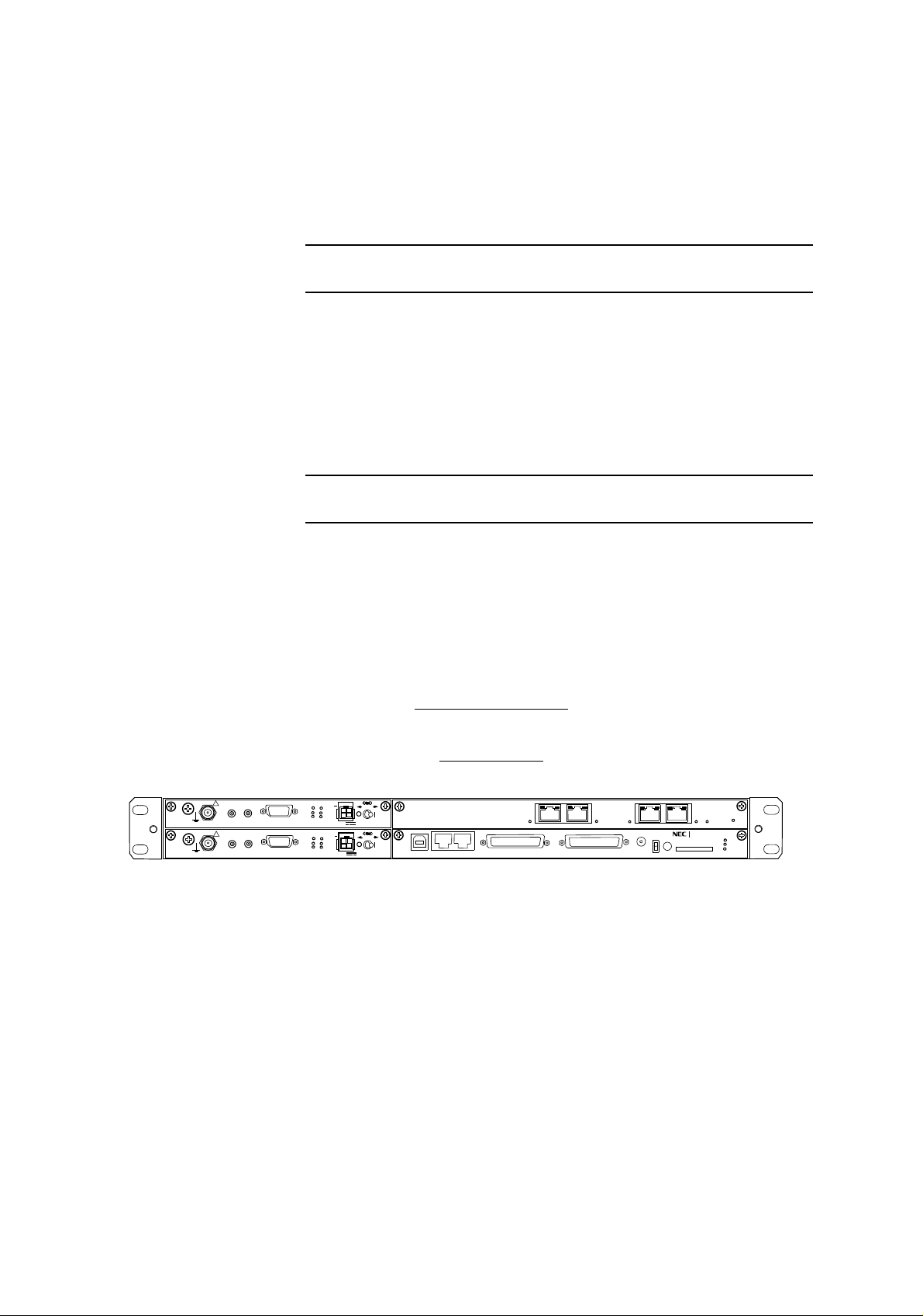
A. 4P LAN INTERFACE
Note: The BER measurement can not be performed
for the channel
which is set to Not Used or the channels shared with LAN.
TRANSMITTING END
4P LAN INTFC
IF IN/OUT
!
XIF OUT
G
!
XIF IN
IF IN/OUT
XIF IN
XIF OUT
XPIC CTRL
XPIC CTRL
RESET
RESET
TX
RX
XPIC
TX
RX
XPIC
G
PULL
PWR
ODU
MD/
CBL
PWR
SELV
G
PULL
PWR
ODU
MD/
CBL
PWR
SELV
NMS
LCT
NE
AUX/ALM
100M
PORT 1 PORT 2
100M
SC IN/OUT
100M
PORT 3 PORT4
PROTECT
EOW
CALL
ALM
100M
PASOLINK NEO
MAINT
MEMORY
IDU
MMC
ALM
G
5-17
Page 19

CORRECTIVE MAINTENANCE ROI-S05751
Chart 5-2 (Cont’d)
Step Procedure
1 At both transmitting and receiving ends, set the BER test set as
follows:
Note: Operation of the TX SW and RX SW are not required in
1+0 system for the following.
2 In HS system, set the TX SW to No.1 or No.2 to “On” condition
at transmitting end (refer to Chart 2-3),
3 At receiving end, set the RX SW to either No.1 or No.2 to “On”
condition,
4 Measure BER at required CH and confirm that the values are
indicated as follows:
Requirement: 1 x 10
–12
or less
5 At receiving end, change setting of the RX SW to opposite No.1
or No.2 from it in step 5 and confirm that the measured value
satisfies requirement as in step 6,
6 Change setting of the TX SW to opposite No.1 or No.2 from it
in step 4 and confirm that the measured value satisfies
requirement given in step 6,
7 At receiving end, change setting of the RX SW to opposite No.1
or No.2 from it in step 7 and confirm that the measured value
satisfies requirement given in step 6,
8 Restore all connections and controls to normal.
5-18
Page 20
ROI-S05751 CORRECTIVE MAINTENANCE
Chart 5-2 (Cont’d)
Step Procedure
B. OPTICAL INTERFACE
Caution: To avoid damage to your e
yes, do not stare into laser
beam or view directly with optical instruments. (Class
1 Laser Product).
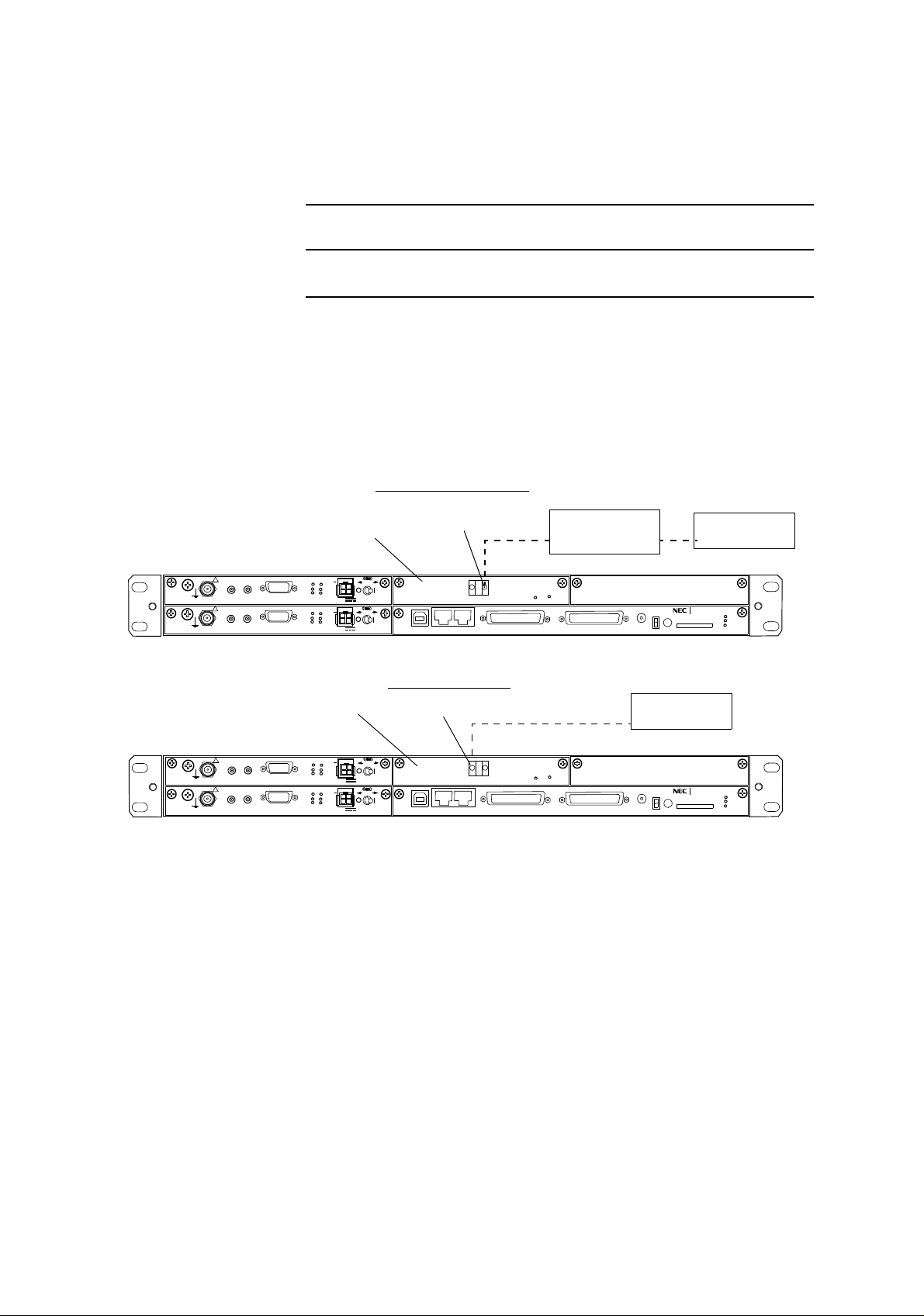
1 At the transmitting end, disconnect OPT cable from the STM1
IN connector on the OC-3 INTFC (see Fig. 5-2),
TRANSMITTING END
OC-3 INTFC
IF IN/OUT
!
XIF OUT
G
!
XIF IN
IF IN/OUT
XIF IN
XIF OUT
XPIC CTRL
XPIC CTRL
RESET
RESET
TX
RX
XPIC
TX
RX
XPIC
G
PULL
PWR
ODU
MD/
CBL
PWR
SELV
G
PULL
PWR
ODU
MD/
CBL
PWR
SELV
OC-3 (OPT) IN
OC-3 IN
OC-3 OUT
LCT
NMS
NE
ONLINE
AUX/ALM
IDU
RECEIVING END
OC-3 INTFC
IF IN/OUT
!
XIF OUT
G
!
XIF IN
IF IN/OUT
XIF IN
XIF OUT
XPIC CTRL
XPIC CTRL
RESET
RESET
TX
PWR
RX
ODU
XPIC
MD/
CBL
SELV
TX
PWR
RX
ODU
XPIC
MD/
CBL
SELV
OC-3 (OPT) OUT
G
PULL
PWR
G
PULL
PWR
OC-3 IN
OC-3 OUT
LCT
NMS
NE
ONLINE
AUX/ALM
IDU
OPTICAL
VARIABLE
ATTENUATOR *
ALM
SC IN/OUT
ALM
SC IN/OUT
(Blank)
PASOLINK NEO
PROTECT
EOW
CALL
MMC
STM/SONET
ANALYZER
(Blank)
PASO LINK NEO
PROTECT
EOW
CALL
MMC
STM/SONET
ANALYZER
MAINT
MEMORY
MAINT
MEMORY
IDU
IDU
G
G
Equipped with OC-3 Optical Interface
Fig. 5-2 BER Measurement for OC-3 Signal
2 At the receiving end, disconnect the OPT cable from the STM1
OUT connector on the OC-3 INTFC (see Fig. 5-2),
3 At both transmitting and receiving
ends, set the STM/SONET
Analyzer as follows:
5-19
Page 21

CORRECTIVE MAINTENANCE ROI-S05751
Chart 5-2 (Cont’d)
Step Procedure
OC-3 INTFC(OPTICAL)
• Bit rate : 155.52 Mbps
• Code format : OC-3, NRZ
• Level S-1.1
IN : −8 to −28 dBm/ −10 to −34 dBm
OUT : −8 to −15 dBm/ 0 to −8 dBm
• Wave length
IN : 1310 nm
OUT : 1310 nm
L-1.1
Note: Operation of the TX SW and RX SW are not required in
1+0 system.
4 In HS system, set the TX SW to No.1 or No.2 to On condition at
transmitting end, (refer to
Chart 2-3)
5 At receiving end, set the RX SW to either No.1 or No.2 to On
condition,
6 Measure BER and confirm that the values are indicated as
follows:
Requirement: 1 x 10
7 At receiving end, change setting of t
–12
or less
he RX SW to opposite No.1
or No.2 from it in step 5 and confirm that the measured value
satisfies requirement given in step 6,
8 Change setting of the TX SW to opposi
te No.1 or No.2 from it
in step 4 and confirm that the measured value satisfies
requirement given in step 6,
9 At receiving end, change setting of t
he RX SW to opposite No.1
or No.2 from it in step 7 and confirm that the measured value
satisfies requirement given in step 6,
5-20
10 Restore all connections and controls to normal.
Page 22
ROI-S05751 CORRECTIVE MAINTENANCE
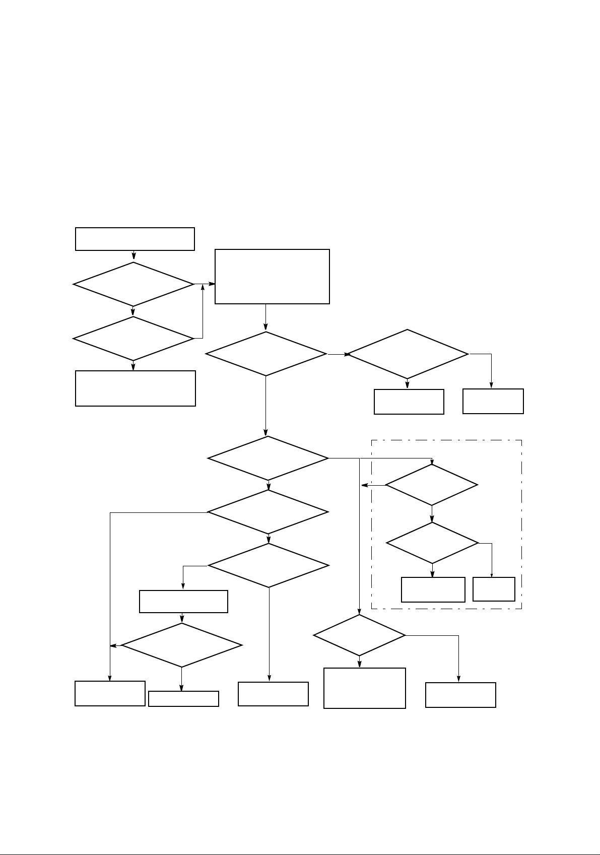
5.1.5 Trouble Shooting Flow
When alarm condition occurs, red alarm LEDs on the IDU are lit except
when there is a power supply failure. Faults can be distinguished using the
LED indicators on the front panel of the IDU. Connect the LCT to the
equipment and check the equipment conditions in according with the flow
chart are shown in Fig. 5-3 to Fig. 5-5.
Is ODU ALM indicator (red) on the
IDU lighted?
YES
Is
IDU ALM indicator
(red) on the IDU
lighted?
YES
both IDU and ODU ALM
Check the IF cable connection and
connectors whether the cable is
open or short circuit.
Are
indicators (red)
flashing?
YES
Connect the LCT to the IDU and
check ALARM/STATUS menu.
Check every items whether
NO
indicated status is alarm or normal.
NO
TX Input
indicated normal?
YES
Is
NO
cable length and cable loss are
The
IF cable type,
used standard.
YES
Replace the ODU
with a spare.
NO
Change the IF
cable to standard.
NO
Replace the ODU
with a spare.
NO
NO
Reset CPU of the ODU.
ODU ALM is indicated
Is
normal?
YES
End
TX power of the ODU is
APC of the ODU is indicated
ODU CPU is indicated
Is
indicated normal?
YES
Is
normal?
YES
Is
normal?
YES
Check the RX
section of the ODU.
NO
Is TX power
vary with ATPC manual
control?
Replace the ODU with a
spare, if TX power alarm
continues when
temperature is improved.
Fig. 5-3 ODU TX Section Troubleshooting Flowchart
YES
YES
Is
LO REF indicated
normal?
NO
Is
XREF (MODEM)
indicated normal?
NO
Replace the ODU
with a spare.
NO
Replace the ODU
with a spare.
For XPIC
YES
Check the
IDU section.
5-21
Page 23
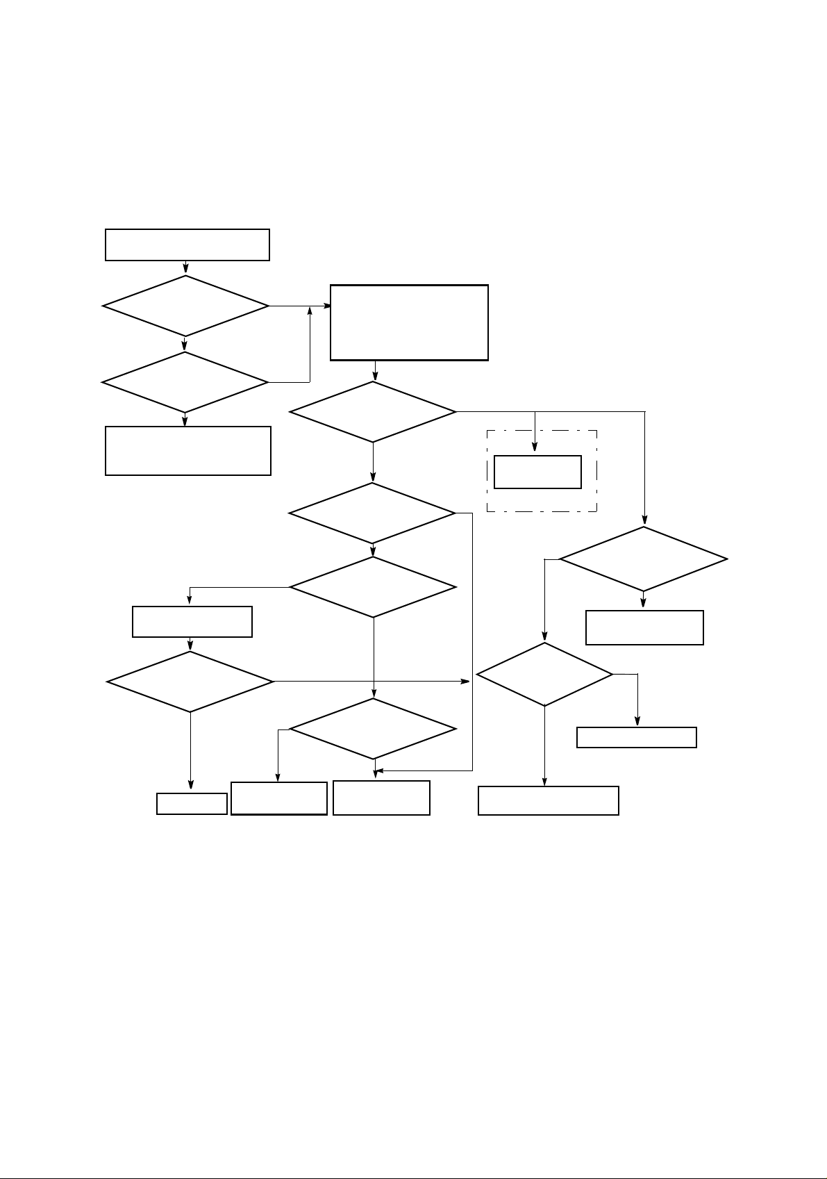
CORRECTIVE MAINTENANCE ROI-S05751
Is ODU ALM indicator (red) on
the IDU lighted?
YES
IDU ALM indicator (red)
both IDU and ODU ALM
Check the IF cable connection and
connectors whether the cable is
open or short circuit.
Is
lighted?
YES
Are
indicators (red)
flashing?
YES
Reset CPU of the ODU
ODU ALM is indicated
Is
Normal?
YES
NO
NO
NO
NO
NO
Connect the LCT to the IDU and
check ALARM STATUS menu.
Check every items whether
indicated status is Alarm or Normal.
Is
RX Level
indicated Normal?
YES
APC of the ODU is indicated
ODU CPU is indicated
Is
Normal?
YES
Is
Normal?
YES
Is
ODU TX section are
checked?
NO
NO
Check the ODU
TX section.
For XPIC
NO
RSL monitor vary at random
Are
frequency value at
opposite site and local
site correct?
YES
Set proper frequency.
Is RXLEVEL by
interval?
YES
Check fading or
interference.
NO
5-22
End
YES
Check the TX
section of the ODU.
Replace the ODU
with a spare.
Check Antenna system or
Replace the ODU with a spare.
Fig. 5-4 ODU RX Section Troubleshooting Flowchart
Page 24
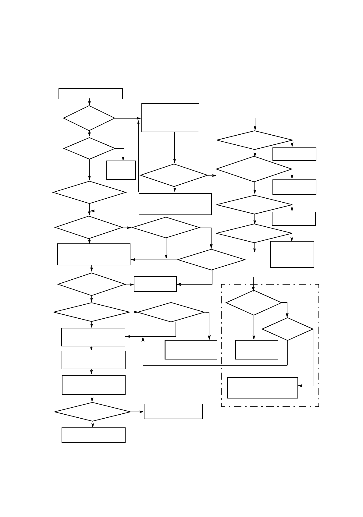
ROI-S05751 CORRECTIVE MAINTENANCE
Is IDU ALM indicator (red) on
the IDU lighted?
ODU ALM indicator
both IDU and ODU ALM
Select IF Loopback from
Maintenance1 menu in the
Maintenance Menu on the LCT.
MOD/DEM indicated
Output LOS indicated
Connect the SONET Analizer for
BER measurement.
Select Far End loopback from
Control menu in the Maintenance
Menu on the LCT.
YES
Is
(red) on the IDU
lighted?
YES
Is
PWR LED on the
MODEM lit?
YES
Are
indicators (red)
flashing?
NO
Is
IDU indicated
Normal?
YES
Is
Normal?
YES
Is
Normal?
NO
NO
Replace Fuse
in the
MODEM.
A
NO
NO
Connect the LCT to the IDU
NO
YES
and check ALARM STATUS
menu. Check every items
whether indicated status is
Alarm or Normal.
Is
IF Cable indicated
Short?
Check the IF cable connection and
connectors whether the cable is
open or short circuit.
Is
MOD/DEM indicated
Normal?
YES
YES
Replace the MODEM
with a spare.
YES
Is
Input LOS indicated
Normal?
Check associated DTE
and cable connection.
YES
YES
NO
A
NO
Is
MOD indicated
Normal?
NO
NO
AIS Generated indicated
AIS or MS-AIS Received
status of LAN INTFC indicated
Is
Normal?
YES
Is
indicated
Normal?
YES
Is
CH Usage indicated
Normal?
YES
Is
Normal?
YES
A
Is
XREF indicated
normal?
NO
Replace the MODEM
with a spare.
Check associated
DTE at opposite site.
Check associated
DTE at local site.
Set CH usage correct.
Perform LAN device
reset and check LAN
cable or associated
external equipment.
XIF indicated
normal?
NO
NO
NO
NO
For XPIC
YES
Is
YES
NO
Display ALARM/STATUS items
from main menu on the LCT
again.
Output LOS indicated
Check associated DTE and
Is
Normal?
YES
cable connection at
opposite site.
Fig. 5-5 IDU Section T
NO
( ) INTFC faulty.
Replace the ( ) INTFC
roubleshooting Flowchart
Check the XIFcable, IDU and ODU
of the opposite pol. CH or setting of
the opposite station.
5-23
Page 25
CORRECTIVE MAINTENANCE ROI-S05751
5.2 Replacement
The replacement procedures of the IDU and ODU is described below.
5.2.1 ODU Replacement
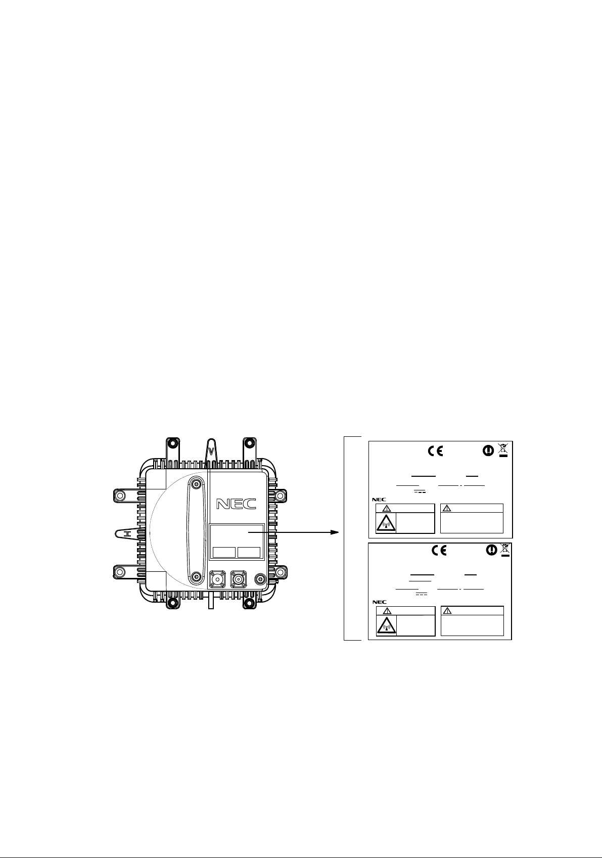
The procedures for replacing the ODU with a spare are given in the Chart
5-3. The label attached to the side of ODU indicates the ODU type (see Fig
5-6). To replace the ODU, prepare another ODU of the same type as
indicated on the label of the failed one.
Check the name plate of the spare ODU
coincided, the ODU can be replaced.
Caution: Do not remove/connect the IF cable with the IDU power
ON. T
urn the IDU power OFF before connecting/
disconnecting the IF cable, or equipment may be damaged.
Caution: To avoid microfonic properties, occurrence of bit errors,
when inst
alling the ODU on the HYB or OMT, protect the
ODU from mechanical knocks which is not be replaced.
NLite E
RX LEV
IFL
MON
6-38 GHz ODU
FG
. When the indicated items are
NLITE E
TRP-( )G-1B
OUTDOOR UNIT (NHG)
SHIFT FREQUENCY
SERIAL No.
WEIGHT 3.5kg/ - 48V
NEC Corporation TOKYO JAPAN
CAUTION
Non-ionizing
radiation
NLITE E
TRP-( )G-1B
OUTDOOR UNIT (NHG)
SHIFT FREQUENCY
TX FREQUENCY
SERIAL No.
WEIGHT 3.5kg/ - 48V
NEC Corporation TOKYO JAPAN
CAUTION
Non-ionizing
radiation
0678
MHz SUB BAND
DATE
0.5A
-48V INPUT
Power down IDU before
disconnection or
connection of cable.
0678
MHz SUB BAND
MHz
DATE
0.5A
-48V INPUT
Power down IDU before
disconnection or
connection of cable.
(NWA-009034)
TX
HIGH/LOW
MADE IN JAPAN
(NWA-009034)
TX
HIGH/LOW
MADE IN JAPAN
5-24
Fig. 5-6 ODU Type and Frequency Indication Label
Note: Before replacing the ODU in XPIC, perform the control of XPIC
Local and XPIC Remote Reset by the LCT for Main Master or
Sub Master channel that is to be used online.
The mounting and demounting the ODU from/to antenna, refer to the
Installation and Initial
Line up in Section III.
Page 26
ROI-S05751 CORRECTIVE MAINTENANCE
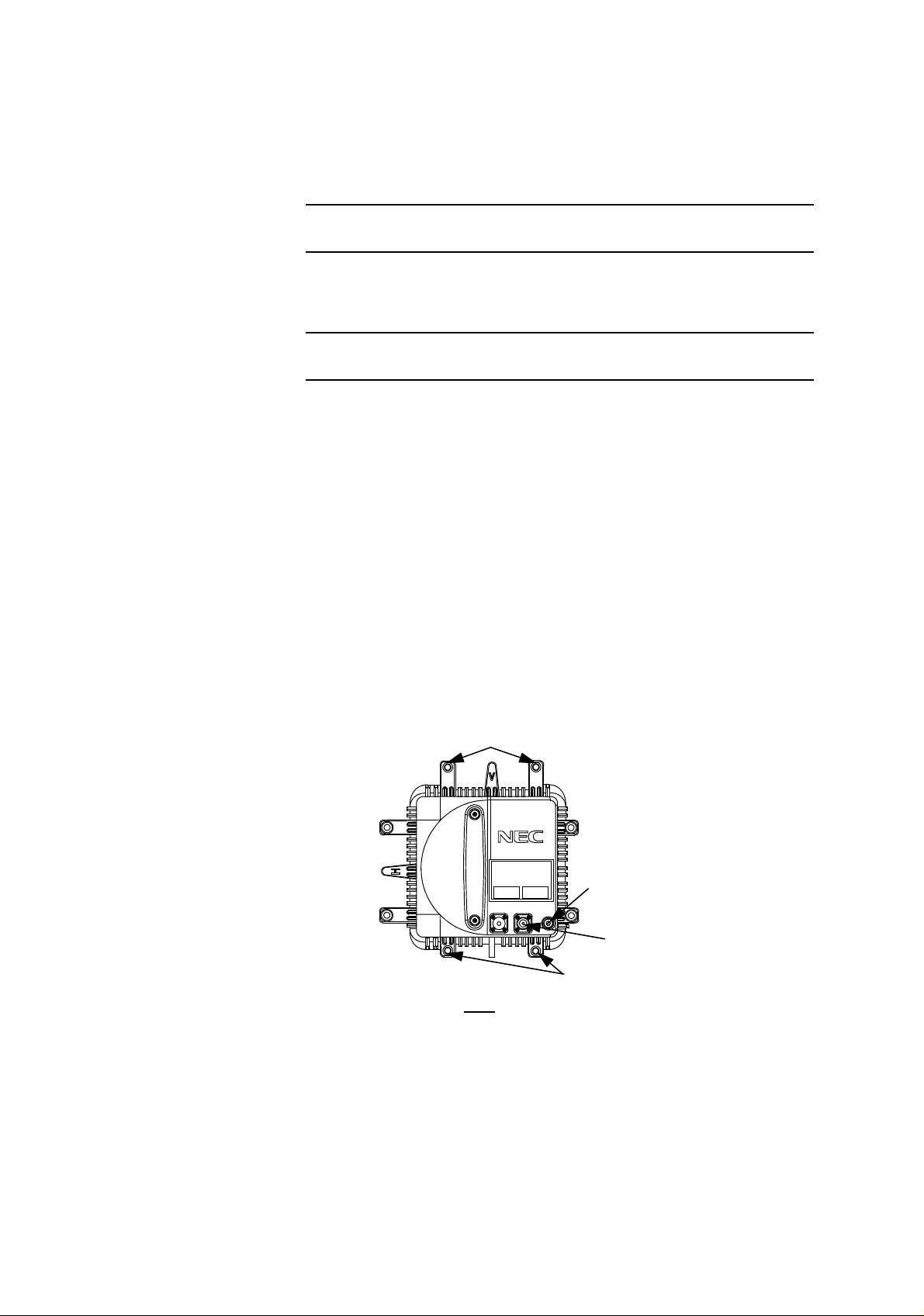
Chart 5-3 ODU Replacement
Apparatus:
T type hexagonal driver
Step Procedure
REMOVING
1 For 1+1 configuration, switchover the TX SW and RX SW for
the
standby channel is to be replaced,
2 Turn off the power switch on the MODEM which is connected
to the ODU is to be replace
d,
3 Remove the self-bonding tape from the IF IN/OUT connector
4 Disconnect the IF cable from the IF
IN/OUT connector on the
,
ODU,
5 Disconnect ground cable from the FG terminal on the ODU,
6 Loosen four bolts fixed the ODU with a T type hexagonal
driv
er,
SCREWS
NLite E
GROUND
RX LEV
MON
IFL
FG
SCREWS
CABLE
IF
CABLE
ODU
7 Remove the ODU from the bracket,
5-25
Page 27
CORRECTIVE MAINTENANCE ROI-S05751
Chart 5-3 (Cont’d)
Step Procedure
MOUNTING
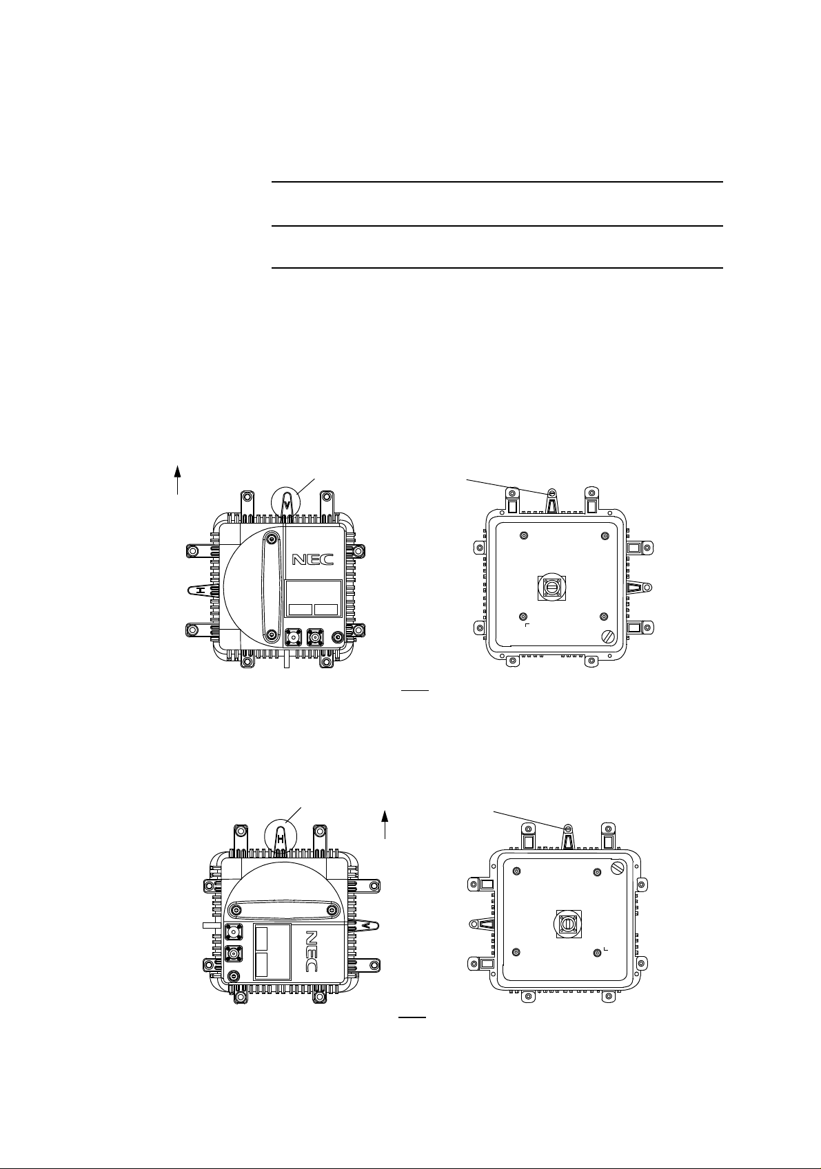
8 When the ODU is used for vertical polarization, rotate the ODU
so
that the plate marked V is on top,
Note: Remove the protection metallic plate covering the waveguide
hole on ODU.
UP
9 When the ODU is used for horizontal polariz
ation, remove the
guide pin fixed on the plate marked V,
PLATE MARKED V
NLite E
RX LEV
IFL
MON
FG
Guide Pin
ODU
V POLARIZATION
10 Insert the guide pin removed in step 8 behind of the plate
ma
rked H,
11 Rotate the ODU so that the
PLATE MARKED H
Guide Pin
plate marked H is on top,
5-26
UP
RX LEV
MON
IFL
FG
NLite E
ODU
H POLARIZATION
Page 28

ROI-S05751 CORRECTIVE MAINTENANCE
Chart 5-3 (Cont’d)
Step Procedure
12 Fit the spare ODU onto the bracket,
Note: Be careful not to damage the flange and O-ring.
13 Mount the spare ODU onto the bracket and tighten the four
screws on the ODU,
14 Reconnect the IF cable to the IF IN/OUT connector on the
ODU,
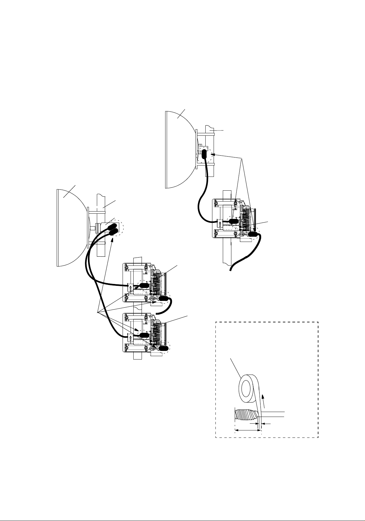
15 Wrap twice the IF IN/OUT connector with self-bonding tape for
waterproofing. (see Fig. 5-7 (1/2) and (2/2))
16 Reconnect ground cable removed in step 4 to FG terminal,
17 Turn on the power switch on the IDU.
5-27
Page 29
CORRECTIVE MAINTENANCE ROI-S05751
ANT
POLE
(*)
ANT
POLE
HYB
ODU
ODU
(*)
ODU
6-8 GHz BAND
Note: * These parts should be wrapped by self-bonding
tape for waterproof.
6-8 GHz BAND
Wrap twice the IF IN/OUT connector with
self-bonding tape for waterproofing.
self-bonding
tape
stretch
ODU
twice
a half of tape width
5-28
Fig. 5-7 Location of Connector for Waterproof (1/2)
Page 30
ROI-S05751 CORRECTIVE MAINTENANCE
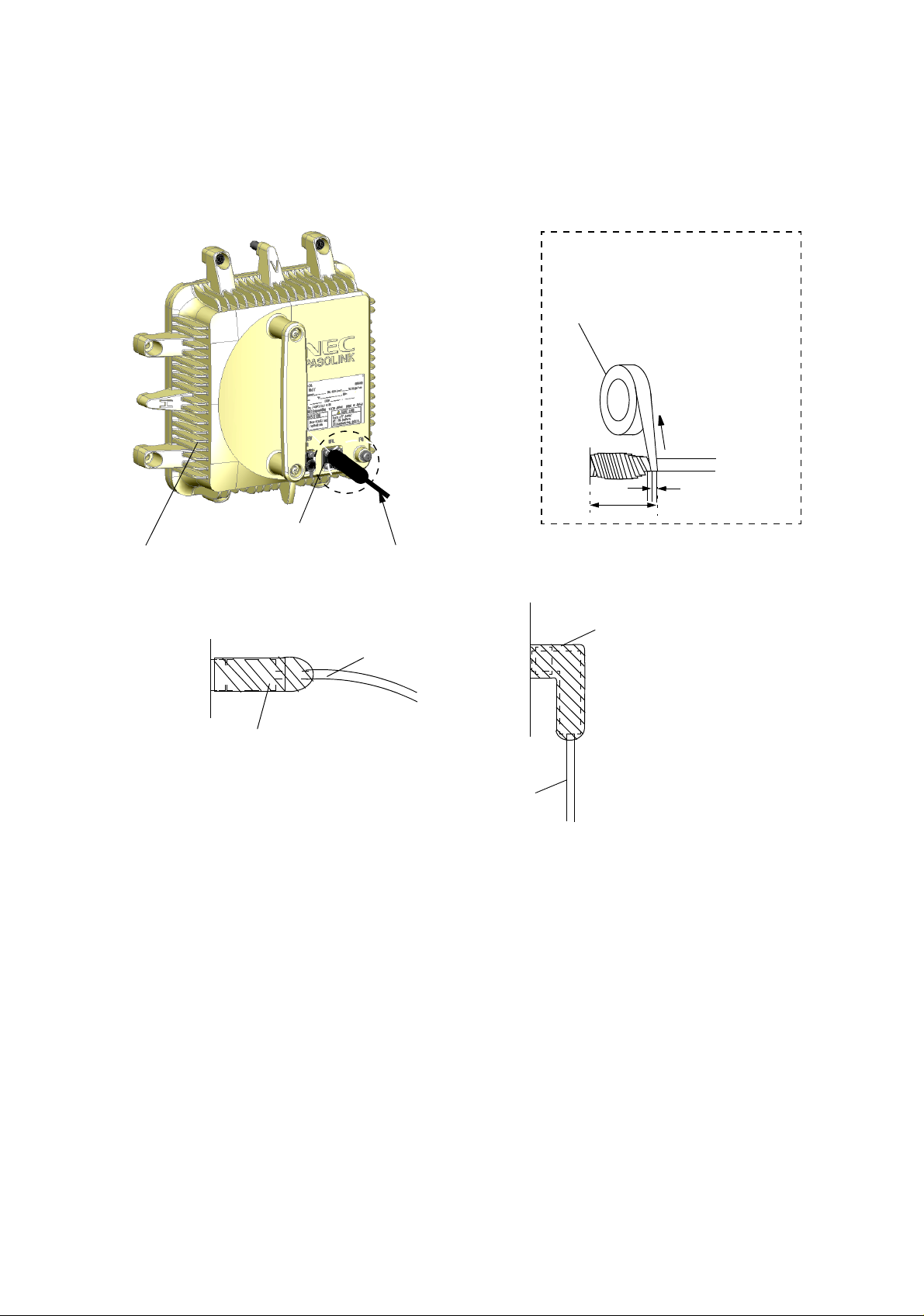
Wrap twice the IF IN/OUT connector with
self-bonding tape for waterproofing.
self-bonding
tape
stretch
ODU
a half of tape width
ODU
twice
CONNECTOR
This part should be wrapped by
self-bonding tape for waterproof.
ODU
SELF-BONDING TAPE
Note: The self-bonding tape should be prepared by customer.
Fig. 5-7 Location of Connector for Waterproof (2/2)
IF CABLE
SELF-BONDING TAPE
ODU
IN CASE OF L−ANGLE
IF CABLE
5-29
Page 31

CORRECTIVE MAINTENANCE ROI-S05751
5.2.2 IDU and Module Replacement
The procedures for replacing IDU/module with a spare are given in the
Chart 5-4.
Chart 5-4 IDU and Module Replacement
Caution: Persons performing maintenance must take necessary steps
to avoid electro-static discharge which may damage the
modules or cause error. Wear a conductive wrist strap
connected to the grounded (G) jack on the front of the
equipment shelf. This will minimize static build-up during
maintenance. (see Fig. 2-1 in Chapter 2).
Caution: Do not remove/connect the IF cable with the IDU power
ON. Turn the IDU power OFF before connecting/
disconnecting the IF cable, or equipment may be damaged.
This chart contains:
A. Module replacement
B. IDU replacement
Apparatus:
Suitable Screwdriver
Step Procedure
A. MODULE REPLACEMENT
Note: Be careful do not touch the electric parts and printed
circuit on the module.
Note: The top surface of the IDU above MODEM is hot in
operation.
Note: The maintenance personnel should report starting
replacement from a station to the relevant station.
1 Referring to Chart 2-1, set the IDU to maintenance ON
condition by LCT,
5-30
2 For 1+1 configuration, switchover the TX SW and RX SW for
the standby channel from the working channel which is to be
replaced,
Page 32

ROI-S05751 CORRECTIVE MAINTENANCE
Chart 5-4 (Cont’d)
Step Procedure
Removing MODEM
3 When the MODEM will be replaced, turn off the power switch
on the corresponding MODEM which is to be replaced,
4 Disconnect cables as following order,
(1) Disconnect power supply cable from SELV connector.
(2) Disconnect IF cable from IF IN/OUT connector. The
adapter is reused.
(3) Disconnect ground cable from the ground terminal.
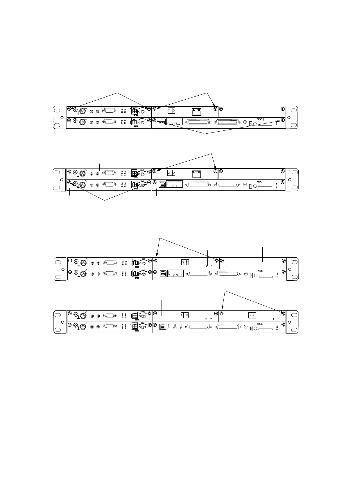
5 Loosen two screws on the MODEM module, (See Fig. 5-8)
6 Remove the MODEM module from the IDU shelf,
Mounting MODEM
1 When the MODEM is replaced, check that the power switch is
set to Off position,
2 Align the MODEM to the shelf, then push it in until the multipin
connector firmly fits,
3 Tighten the two screws on the module,
4 Connect cables as following order,
(1) Connect ground cable to the ground terminal.
(2) Connect IF cable with adapter to IF IN/OUT connector.
(3) Connect power supply cable to SELV connector.
5 Turn on the power switch on the MODEM,
6 Check that the MODEM is normal on the Alarm/Status display,
7 Check that the installed MODEM module exists in the
INVENTRY list,
8 Check the operation of the replaced MODEM module,
9 Referring to Chart 2-1, set the IDU to maintenance OFF
condition by LCT.
5-31
Page 33
CORRECTIVE MAINTENANCE ROI-S05751
Chart 5-4 (Cont’d)
Step Procedure
Replacement of the OC-3 (Optical) INTFC in APS
Caution: Do not stare at the laser beam or look at it directly with
optical instruments. Otherwise, it may hurt your eyes (Class
1 Laser Product)
For the OC-3 (OPTICAL) INTFC replacement in APS configuration, the
OC-3 (OPTICAL) INTFC can be replaced without power OFF and not
affect traffic when doing replacement as following order. (When the traffic
is not applied to the system, turn off the power switch before performing
the replacement of the module.). The maintenance personnel should report
starting replacement from a station to the relevant station.
1 Referring to Chart 2-1, set the IDU to maintenance ON
condition by LCT,
2 Click on “APS Manual Control” from “Maintenance 1” menu,
3 Switchover the module is to be replaced to OFF LINE. Click on
the “Working” or “Protection” button and click on the “Set”
button, then, value turns to selected side for ON LINE,
---Maintenance1---
Item Value Setting
Maintenance On
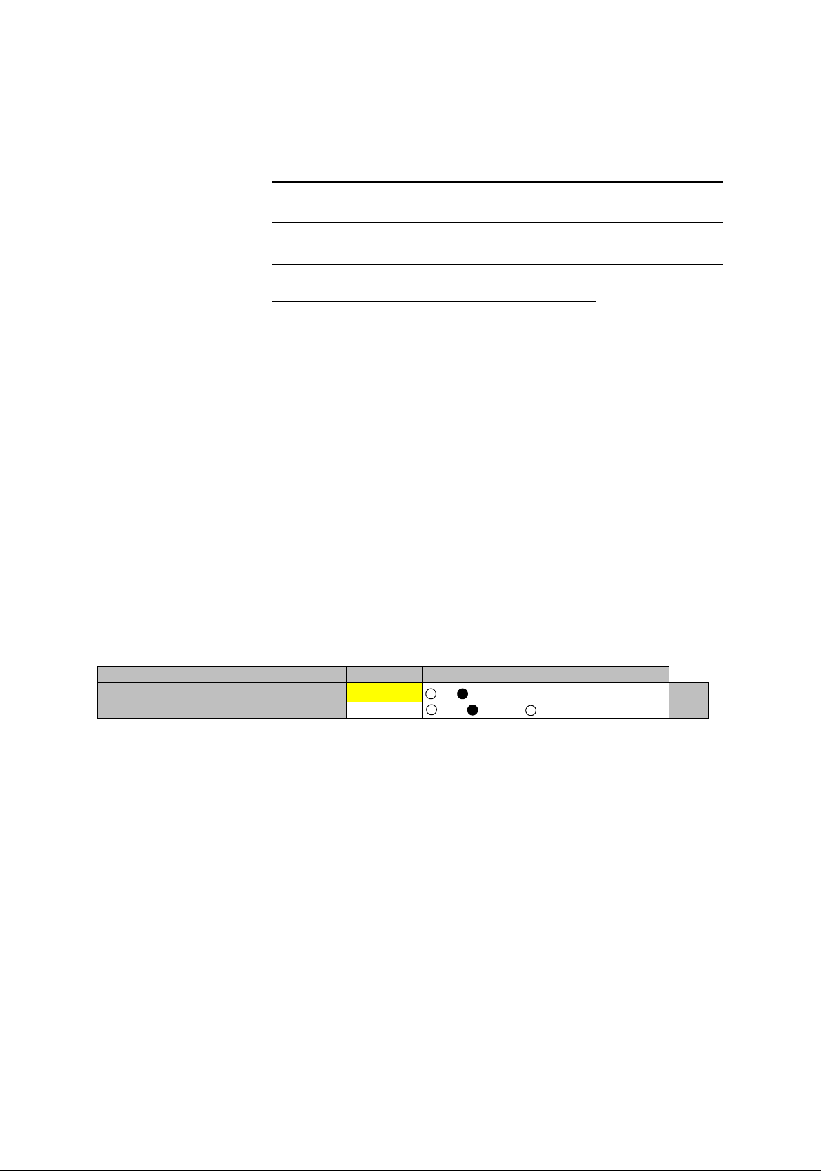
APS Manual Control Working Auto Working Protection Set
Off On
Set
4 Check that the “ON LINE” LED is unlit on the OC-3
(OPTICAL) INTFC which is to be replaced,
5 Set the PROTECT SW on the module front to ON (for upper
position), then the MAINT LED starts the blink,
The module can be replaced under the MAINT LED is blinking,
(a) There is need to install the MMC. The MEMORY LED blinks
during the data is uploading to the MMC, the MAINT LED
starts the blink after upload of the data has been completed.
(b) When the CTRL becomes the PROTECT mode, LCT
connection takes timeout.
5-32
6 Disconnect optical cables from OC-3 OUT and OC-3 IN
connectors on the OC-3 (OPTICAL) INTFC module is to be
replaced,
Page 34

ROI-S05751 CORRECTIVE MAINTENANCE
Chart 5-4 (Cont’d)
Step Procedure
7 Loosen two screws on the OC-3 (OPTICAL) INTFC module is
to be replaced, (See Fig. 5-11)
8 Extract the OC-3 (OPTICAL) INTFC module from the IDU
shelf,
Note: Be careful not catch the module on the cable when
extracting the module. If the module caught on the live
cables, it may be caused radio link error.
9 Install the spare OC-3 (OPTICAL) INTFC module into the IDU
shelf,
10 Connect the OPT cables to the OC-3 OUT and OC-3 IN
connectors on the OC-3 (OPTICAL) INTFC module,
11 Set the PROTECT SW on the module front to OFF (for lower
position), then the MAINT LED turns to lit,
When the PROTECT SW turns to OFF, it will appear
momentary that events have been latched.
12 Check that the OC-3(1) and OC-3(2) are normal on the Alarm/
Status display,
13 Check that the installed OC-3 (OPTICAL) INTFC module
exists in the INVENTRY list,
14 Check the operation of the replaced OC-3 (OPTICAL) INTFC
module,
15 Click on the “Auto” button and click on the “Set” button, then,
value turns to Auto,
16 Click on the “Off” button of Maintenance and Click on the “Set”
button,
17 This work finishes.
5-33
Page 35
CORRECTIVE MAINTENANCE ROI-S05751
Chart 5-4 (Cont’d)
Step Procedure
System Upgrade for APS of OC-3 (OPTICAL) INTFC
Caution: To avoid eye damage, do not stare at the laser beam or look
at it directly with optical instruments. (Class 1 Laser
Product)
For the change of OC-3 (OPTICAL) INTFC system to the APS system,
perform system setup without power OFF and not affect traffic when
doing replacement as following order. The maintenance personnel should
report starting replacement from a station to the relevant station.
1 Referring to Chart 2-1, set the IDU to maintenance ON
condition by LCT,
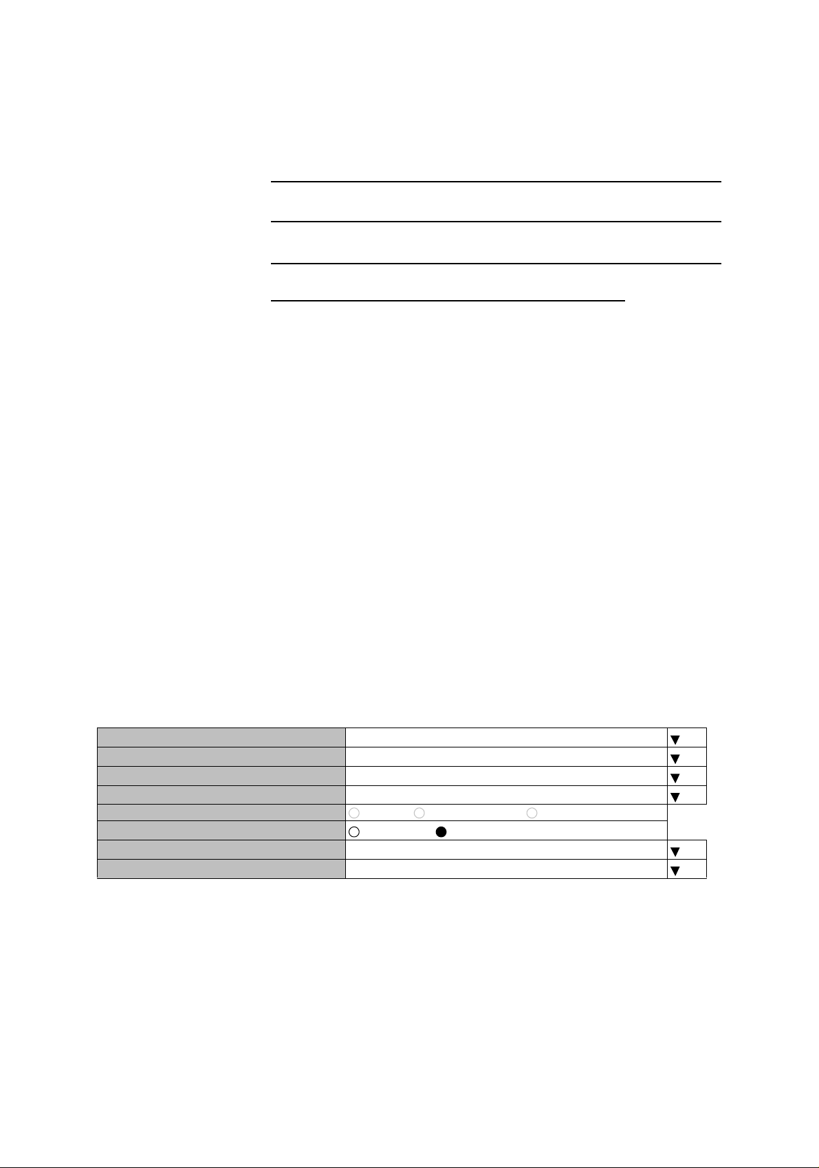
2 Click on the “Equipment Setup” button in “LCT MENU”, then
“Equipment Setup” menu is displayed,
3 Select “OC-3 OPT for APS” from pull-down menu of the
SUB(PROT),
4 Click on the “Available” setting button of the APS Function,
5 Click on the “SET” button in Common area, then “OK” is
displayed in Progress area when the setup is properly executed,
---Equipment Setup---
User Interface SONET OC-3
Redundancy Setting 1+1(Hot Standby TERM)
INTFC (Main) OC-3(OPTICAL)
INTFC (Prot) OC-3 OPT for APS
XPIC Usage Not Used Used(Main Master) Used(Sub Master)
APS Function
Modulation Scheme 128QAM
Transmission Capacity 156MB
Unavailable Available
5-34
Page 36
ROI-S05751 CORRECTIVE MAINTENANCE
Chart 5-4 (Cont’d)
Step Procedure
6 Click on the Provisioning button on “LCT MENU”,
7 Click on the “Forced” control button of the APS Maintenance
Mode item,
----Condition for APS---
APS Maintenance Mode Manual Forced
8 Click on the “SET” button in Common area, then “OK” is
displayed in Progress area when the setup is properly executed,
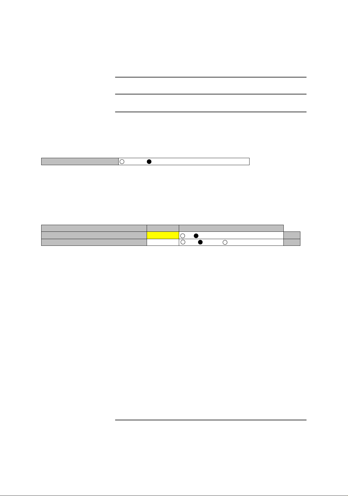
9 In the Maintenance1 menu, Click on the “Working” button of
the APS Manual Control and Click on the “Set” button, then,
value turns to “Working”,
---Maintenance1---
Item Value Setting
Maintenance On
APS Manual Control Working Auto Working Protection Set
Off On
Set
10 Remove the blank cover of the Slot2 for OC-3 INTFC(2),
11 Install the OC-3 (OPTICAL) INTFC module into the Slot2,
12 Tighten two screws of the OC-3 (OPTICAL) INTFC module,
(See Fig. 5-11)
13 Connect the OPT cables to the OC-3 OUT and OC-3 IN
connectors on the OC-3 (OPTICAL) INTFC module,
14 Check that the OC-3(1) and OC-3(2) are normal on the Alarm/
Status display,
15 Check that the installed OC-3 (OPTICAL) INTFC module
exists in the INVENTRY list,
16 Check the operation of the installed OC-3 (OPTICAL) INTFC
module,
17 Click on the “Auto” button and Click on the “Set” button, then,
value turns to Auto,
18 Click on the “Off” button of Maintenance and Click on the “Set”
button,
19 This work finishes.
5-35
Page 37
CORRECTIVE MAINTENANCE ROI-S05751
Chart 5-4 (Cont’d)
Step Procedure
System Change from e/w APS to w/o APS of OC-3 (OPTICAL)
INTFC
Caution: Do not stare at the laser beam or look at it directly with
optical instruments. Otherwise, it may hurt your eyes (Class
1 Laser Product).
For the change of OC-3 (OPTICAL) INTFC system of the APS system to
without APS system, perform system setup without power OFF and not
affect traffic when doing system change as following order. The
maintenance personnel should report starting system change from a station
to the relevant station.
1 Referring to Chart 2-1, set the IDU to maintenance ON
condition by LCT,
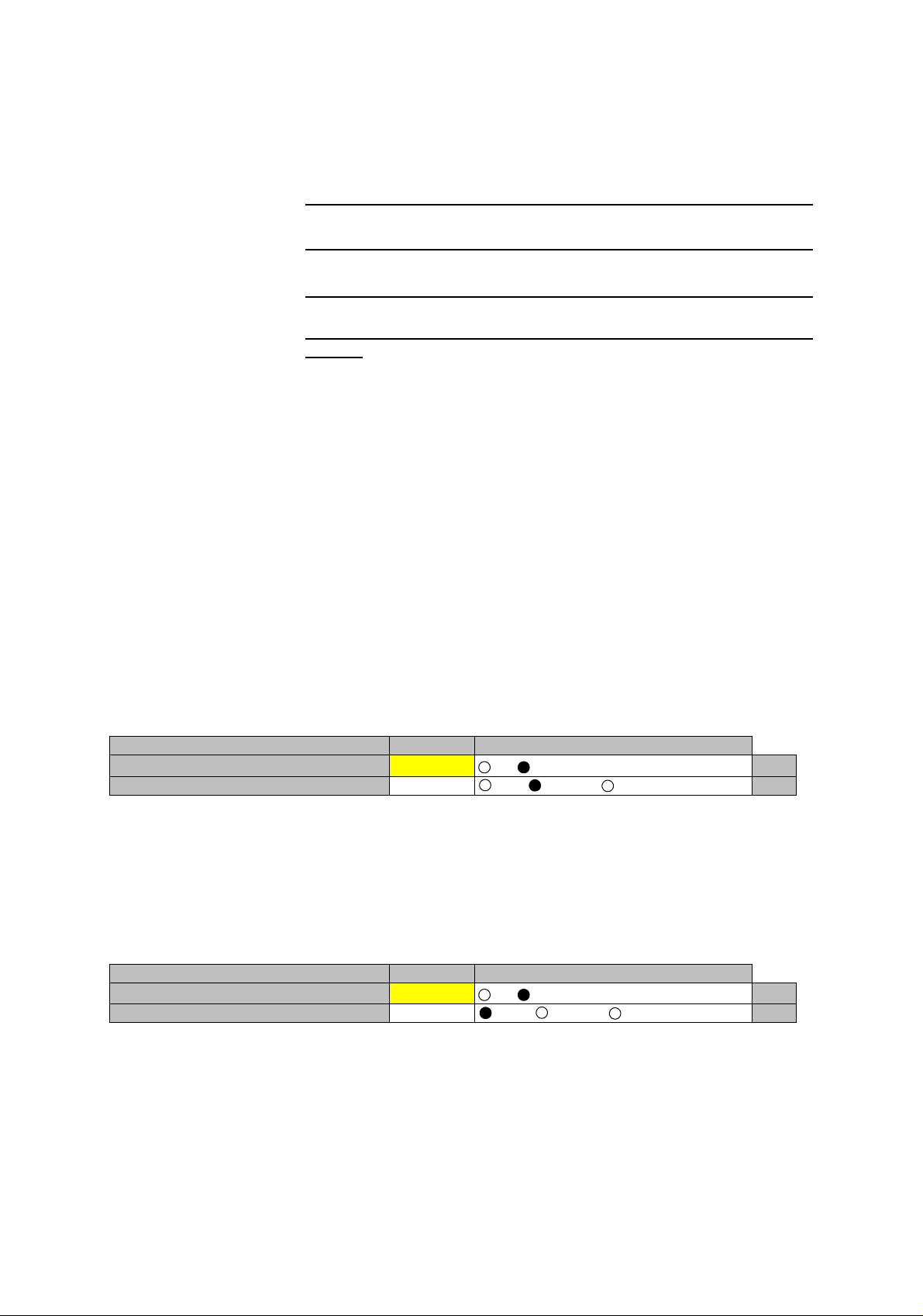
2 In the Maintenance1 menu, Click on the “Working” button of
the APS Manual Control and Click on the “Set” button, when
the Protection side is ON LINE, value turns to “Working”,
---Maintenance1---
Item Value Setting
Maintenance On
APS Manual Control Working Auto Working Protection Set
Off On
Set
3 Click on the “Auto” button of the APS Manual Control and
Click on the “Set” button,
When the Working side is ON LINE, check that the APS
Manual Control is “Auto” mode,
---Maintenance1---
Item Value Setting
Maintenance On
APS Manual Control Auto Auto Working Protection Set
Off On
Set
4 Click on the “Equipment Setup” button in “LCT MENU”, then
“Equipment Setup” menu is displayed,
5-36
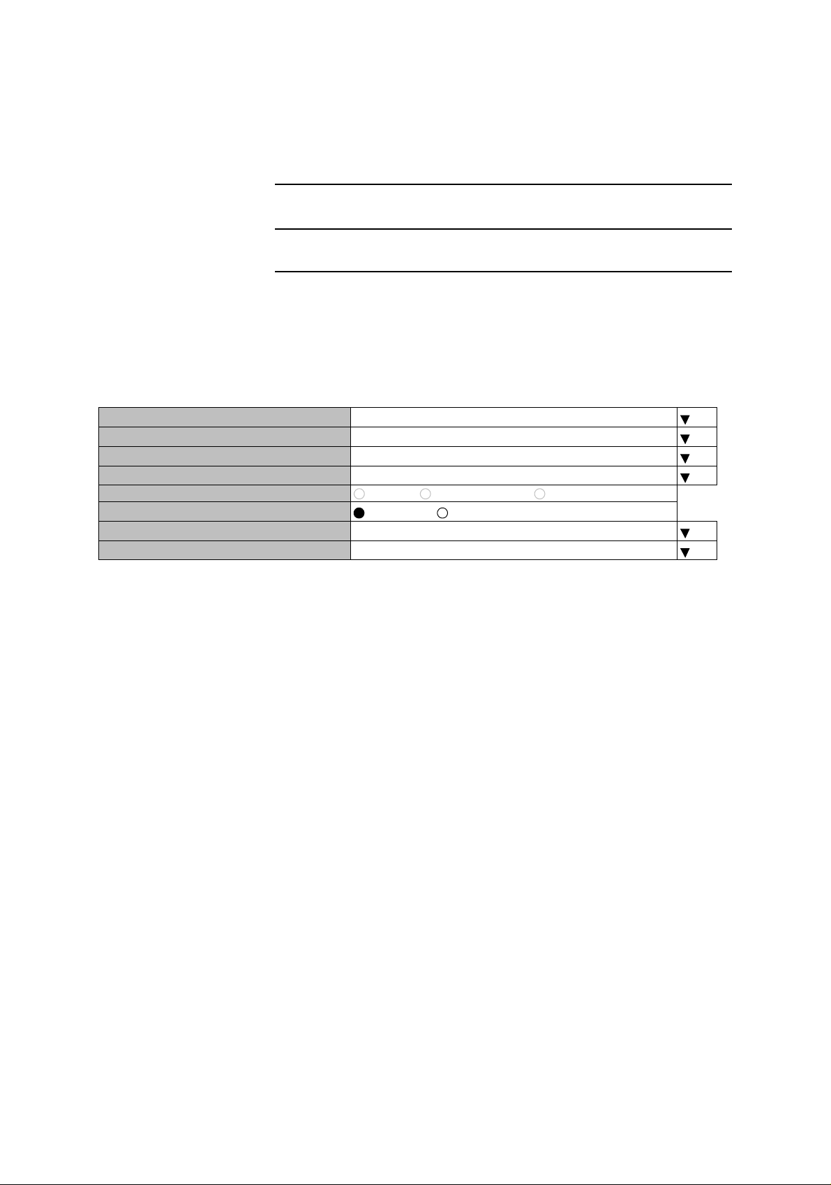
5 Select “Not Used” from pull-down menu of the SUB(PROT),
6 Click on the “Unavailable” setting button of the APS Function,
Page 38
ROI-S05751 CORRECTIVE MAINTENANCE
Chart 5-4 (Cont’d)
Step Procedure
7 Click on the “SET” button in Common area, then “OK” is
displayed in Progress area when the setup is properly executed,
8 Perform step 8 to step 11 when it is needed,
---Equipment Setup---
User Interface SONET OC-3
Redundancy Setting 1+1(Hot Standby TERM)
INTFC (Main) OC-3(OPTICAL)
INTFC (Prot) Not Used
XPIC Usage Not Used Used(Main Master) Used(Sub Master)
APS Function
Modulation Scheme 128QAM
Transmission Capacity 156MB
Unavailable Available
9 Disconnect optical cables from OC-3 OUT and OC-3 IN
connectors on the OC-3 (OPTICAL) INTFC module in the
Slot2,
10 Loosen two screws on the OC-3 (OPTICAL) INTFC module is
to be replaced, (See Fig. 5-11)
11 Extract the OC-3 (OPT) INTFC module from the Slot2,
Note: Be careful not catch the module on the cable when
extracting the module. If the module caught on the live
cables, it may be caused radio link error.
12 Fit the blank cover with two screws to the Slot2,
13 Click on the “Off” button of Maintenance and click on the “Set”
button,
5-37
Page 39
CORRECTIVE MAINTENANCE ROI-S05751
Chart 5-4 (Cont’d)
Step Procedure
Removing OC-3 INTFC, GbE INTFC, CTRL
1 Referring to Chart 2-1, set the IDU to maintenance ON
condition by LCT,
Note: When the CTRL is a failure, replace it with a spare as
explained below.
Note: When the CTRL is replaced without power OFF, refer to the
“Replacing the CTRL Used MMC or LCT”.
---Maintenance1---
Item Value Setting
Maintenance On
Off On
Set
2 Turn off the power switch on the MODEM (both MODEM for
1+1 configuration),
3 Disconnect all the cables connected to the module,
4 Loosen two screws on the module, (See Fig. 5-11),
5 Extract the module,
Note: Be careful to avoid catching the module on the cable
when extracting the module. If the module is caught on
the live cables, it may cause a radio link error.
5-38
Page 40
ROI-S05751 CORRECTIVE MAINTENANCE
1+0 SYSTEM
IDU
G
1+1 SYSTEM
IDU
FG
MODEM No. 2
W/O APS SYSTEM
IDU
G
IF IN/OUT
!
XIF OUT
XIF IN
IF IN/OUT
!
XIF OUT
XIF IN
MODEM No. 1
IF IN/OUT
!
XIF OUT
XIF IN
IF IN/OUT
!
XIF OUT
XIF IN
SCREW
IF IN/OUT
!
XIF OUT
XIF IN
IF IN/OUT
!
XIF OUT
XIF IN
SCREW
MODEM
XPIC CTRL
XPIC CTRL
XPIC CTRL
XPIC CTRL
XPIC CTRL
XPIC CTRL
RESET
XPIC
RESET
RESET
RESET
RESET
XPIC
XPIC
XPIC
RESET
XPIC
SCREW
OC-3 IN
NMS
Gb E INTFC
NE
AUX/ALM
SCREW
(Blank Cover)
SC IN/OUT
nlite e
PROTECT
EOW
CALL
MAINT
MEMORY
IDU
MMC
G
G
TX
RX
TX
RX
PULL
PWR
ODU
MD/
CBL
PWR
SELV
G
PULL
PWR
ODU
MD/
CBL
PWR
SELV
OC-3 OUT
LCT
CTRL
SCREW
Gb E INTFC
TX
RX
TX
RX
PULL
PWR
ODU
MD/
CBL
PWR
SELV
PULL
PWR
ODU
MD/
CBL
PWR
SELV
OC-3 OUT
LCT NMS
OC-3 IN
AUX/ALM
NE
(Blank Cover)
SC IN/OUT
nlite e
PROTECT
EOW
CALL
MAINT
MEMORY
IDU
MMC
FG
CTRL
SCREW
OC-3 (OPTICAL) INTFC
G
TX
RX
XPIC
TX
RX
PULL
PWR
ODU
MD/
CBL
PWR
SELV
G
PULL
PWR
ODU
MD/
CBL
PWR
SELV
LCT
OC-3 IN
OC-3 OUT
NMS
NE
ONLINE
AUX/ALM
ALM
(Blank Cover)
SC IN/OUT
Slot2
nlite e
PROTECT
EOW
CALL
MAINT
MEMORY
IDU
MMC
G
E/W APS SYSTEM
IF IN/OUT
!
G
!
XIF IN
IF IN/OUT
XIF IN
OC-3 (OPTICAL) INTFC
G
PULL
PWR
ODU
MD/
CBL
PWR
SELV
G
PULL
PWR
ODU
MD/
CBL
PWR
SELV
LCT
OC-3 IN
OC-3 OUT
NMS
NE
AUX/ALM
XIF OUT
XIF OUT
XPIC CTRL
XPIC CTRL
RESET
RESET
TX
RX
XPIC
TX
RX
XPIC
Fig. 5-8 Demounting and Remounting Module
SCREW
OC-3 (OPTICAL) INTFC
ALM
ONLINE ONLINE
SC IN/OUT
OC-3 OUT
EOW
PROTECT
CALL
OC-3 IN
nlite e
MMC
MAINT
MEMORY
ALM
G
IDU
5-39
Page 41
CORRECTIVE MAINTENANCE ROI-S05751
Chart 5-4 (Cont’d)
Step Procedure
Mounting OC-3 (OPTICAL) INTFC w/o APS
For the OC-3 (OPTICAL) INTFC mounting without APS, install the
module as following order,
1 Referring to Chart 2-1, set the IDU to maintenance ON
condition by LCT,
---Maintenance1---
Item Value Setting
Maintenance On
2 Turn OFF the power switch on the MODEM,
Off On
Set
3 Align the OC-3 (OPTICAL) INTFC to the shelf, then push it in
until the multipin connector firmly fits,
4 Tighten the two screws on the module,
5 Connect optical cables to OC-3 OUT and OC-3 IN connectors,
Caution: Do not stare at the laser beam or look at it directly with
optical instruments. Otherwise, it may hurt your eyes (Class
1 Laser Product).
6 Turn ON the power switch on the MODEM,
7 Check that the “ON LINE” LED is lit on the OC-3 (OPTICAL)
INTFC which is replaced,
8 Check that the OC-3(1) is normal on the Alarm/Status display,
9 Check that the installed OC-3 (OPTICAL) INTFC module
exists in the INVENTRY list,
10 Check the operation of the installed OC-3 (OPTICAL) INTFC
module,
11 Click on the “Off” button of Maintenance and Click on the “Set”
button,
---Maintenance1---
Item Value Setting
Maintenance Off
Off On
Set
5-40
12 This work finishes.
Page 42
ROI-S05751 CORRECTIVE MAINTENANCE
Chart 5-4 (Cont’d)
Step Procedure
Mounting GbE (OPTICAL) INTFC
For the GbE (OPTICAL) INTFC mounting, install the module as
following order,
1 Referring to Chart 2-1, set the IDU to maintenance ON
condition by LCT,
---Maintenance1---
Item Value Setting
Maintenance On
Off On
Set
2 Turn OFF the power switch on the MODEM,
3 Align the GbE (OPTICAL) INTFC to the shelf, then push it in
until the multipin connector firmly fits,
4 Tighten the two screws on the module,
5 Connect optical cables to 1000BASE-SX OUT and IN
connectors,
Caution: Do not stare at the laser beam or look at it directly with
optical instruments. Otherwise, it may hurt your eyes (Class
1 Laser Product).
6 Turn ON the power switch on the MODEM,
7 Check that the “ON LINE” LED is lit on the GbE (OPTICAL)
INTFC which is replaced,
8 Check that the OC-3(1) is normal on the Alarm/Status display,
9 Check that the installed GbE (OPTICAL) INTFC module exists
in the INVENTRY list,
10 Check the operation of the installed GbE (OPTICAL) INTFC
module,
11 Click on the “Off” button of Maintenance and Click on the “Set”
button,
---Maintenance1---
Item Value Setting
Maintenance Off
Off On
Set
5-41
Page 43
CORRECTIVE MAINTENANCE ROI-S05751
Step Procedure
OC-3/GbE INTFC, CTRL
1 Referring to Chart 2-1, set the IDU to maintenance ON
condition by LCT,
---Maintenance1---
Item Value Setting
Maintenance On
2 Turn OFF the power switch on the MODEM,
3 Check that the switch on the MODEM (both MODEM for 1+1
configuration) is off position,
4 Align the module to the IDU shelf, then push it in until the
multipin connector firmly fits,
Off On
Set
5 Tighten two screws on the module,
6 Connect all cables to the module,
7 Turn on the power switch on the MODEM.
8 Check that the 4P LAN INTFC, OC-3, GbE INTFC, CTRL is
normal on the Alarm/Status display,
9 Check that the installed 4P LAN INTFC, OC-3, GbE INTFC,
CTRL module exists in the INVENTRY list,
10 Check the operation of the replaced 4P LAN INTFC, OC-3,
GbE INTFC, CTRL module,
11 Click on the “Off” button of Maintenance and click on the “Set”
button,
---Maintenance1---
Item Value Setting
Maintenance Off
Off On
Set
5-42
Page 44

ROI-S05751 CORRECTIVE MAINTENANCE
Chart 5-4 (Cont’d)
Step Procedure
Replacing the CTRL Using the MMC or LCT.
This procedure explains how to replace the CTRL using the MMC or LCT.
This procedure is applied when the CTRL is not failed, or when the
equipment configuration data are saved into the MMC or LCT/PNMx.
Note: If the NMS parameters (Network Config.) can not be restored,
then the resetup with the PNMx is required.
The Use of the MMC for the CTRL Replacement
When the MMC is used, the replacement can be performed without the
LCT operation.(The resetup with the PNMx for the Network Config. is
necessary.)
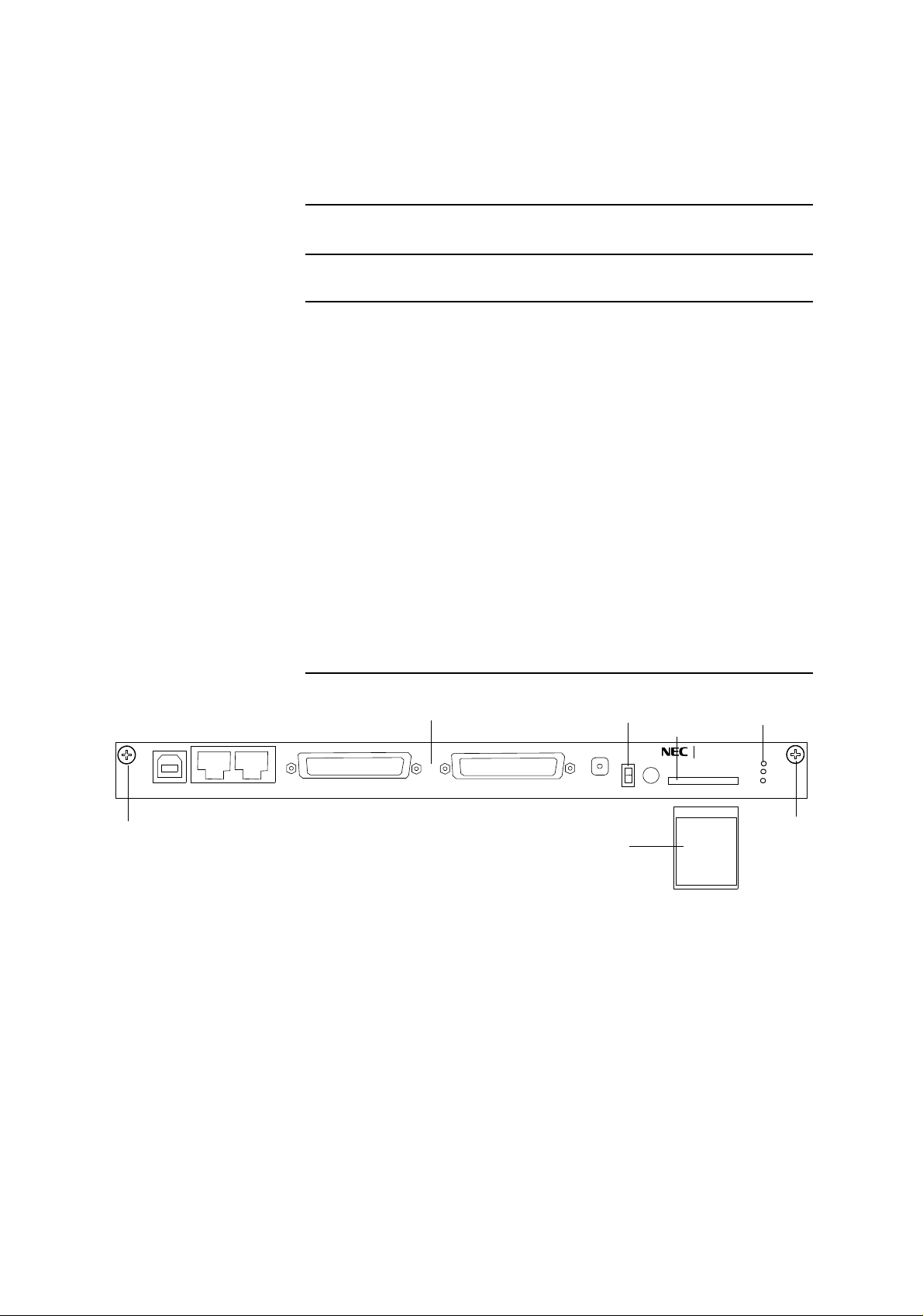
1 Insert the MMC into the MMC slot on the CTRL front, (The
data size to save is approximately 10 kbyte.)
2 Set the PROTECT SW on the CTRL front to ON position (for
upper side). Then, the MAINT LED (amber) on the IDU is lit
and the equipment configuration data gather up and the saving
of data to the MMC start,
3 When the equipment configuration data gather up and data
saving to the MMC has been completed, the MAINT LED on
the IDU blinks slowly, (Check that the MAINT LED blinks
slowly when remove the CTRL.)
4 Remove the cables connected to the CTRL, loosen two fixed
screws and remove the CTRL,
Note: Be careful not catch the module on the cable when
extracting the module. If the module caught on the live
cables, it may be caused radio link error.
5 Prepare the spare CTRL. Set the PROTECT SW on the spare
CTRL to ON position (for upper side), (The PROTECT SW
setting distinguish the normal start up or protected start up.)
Mount the CTRL into the IDU. Check that the MAINT LED on
the IDU blinks. Tighten two screws and connect cables removed
in step 4.
5-43
Page 45
CORRECTIVE MAINTENANCE ROI-S05751
Chart 5-4 (Cont’d)
Step Procedure
6 When the MAINT LED blinks, insert the MMC into the MMC
slot on the CTRL front, which has equipment configuration data
used in the former CTRL,
7 The download of the equipment configuration data start, the
de
ployment is performed. When the CTRL has been made
provision, MAINT LED on the IDU turns to light. Check that
the MAINT LED lights and set the PROTECT SW to OFF
position (for lower side). Then, the equipment configuration
data deploys and data is restored.
8 In the Equipment Setup menu and the Provisioning menu,
confirm that the equipment configurati
are the same as before replacement. Check that neither alarm is
indicated in the Alarm Status.
on and setting conditions
SCREW
LCT NMS
NE
9 The CTRL replacement finishes. Perform the resetup for the
Network
AUX/ALM
Config. since the Network Config. data is not restored.
CTRL
SC IN/OUT
MPROTECT SW
MMC Slot
PROTECT
EOW
MMC
CALL
MAINTE LED
PAS OLI N K NE O
MAINT
MEMORY
MMC
IDU
SCREW
5-44
Page 46
ROI-S05751 CORRECTIVE MAINTENANCE
Chart 5-4 (Cont’d)
Step Procedure
Note: If the NMS parameters (Network Config.) can not be restored,
then the resetup with the PNMx is required.
The Use of the LCT for the CTRL Replacement
When the LCT is used, the replacement can be performed without the
MMC. (The resetup with the PNMx for the Network Config. is necessary.)
1 Referring to Chart 2-1, set the IDU to Maintenance ON
condition
by LCT (Check that the MAINT LED lights.),
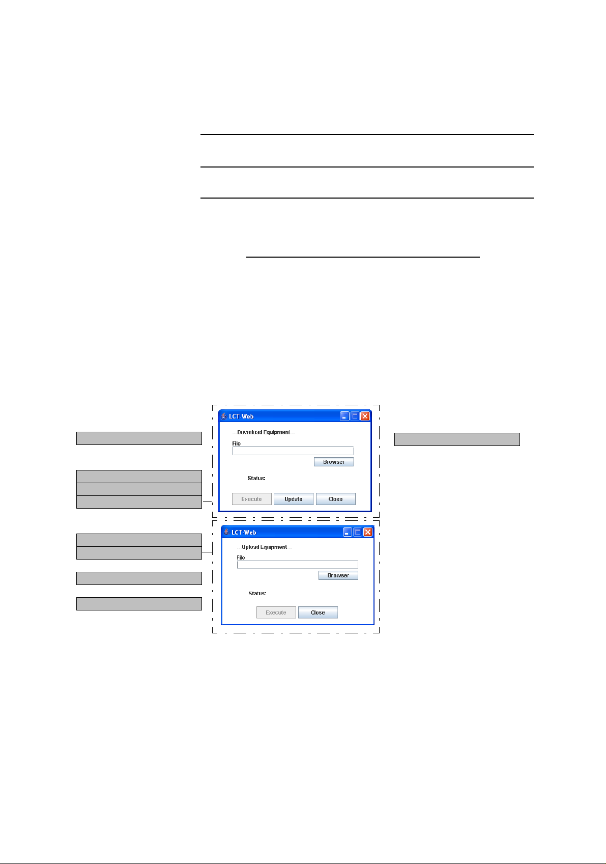
--- Maintenance2 ---
---Control---
CPU Reset
---Download---
Configuration File
Program File
Equipment Config. File
---Upload---
Configuration File
Equipment Config. File
---Date/Time---
Date/Time Setting
---Password---
Password Setting
2 Set the PROTECT SW on the CTRL
upper side). Then, equipment configuration data gather up and
the saving of data start,
---PMON Clear---
front to ON position (for
PMON Clear
3 Select the Maintenance2 from the Maintenance menu, select the
Equipment Config. File of Upload. Enter the directory of the
file name where the uploaded file will be saved (extension is
.cfg),
4 When the upload to the LCT has completed, MAINT LED
blinks slowly (Check that the MAINT LED blinks slowly
when
remove the CTRL.),
5-45
Page 47

CORRECTIVE MAINTENANCE ROI-S05751
Chart 5-4 (Cont’d)
Step Procedure
5 Remove the cables connected to the CTRL, loosen two fixed
screws and remove the CTRL,
Note: Be careful to avoid catching the module on the cable when
extracting the module. If the module is caught on the live
cables, it may cause a radio link error.
6 Prepare the spare CTRL. Set the PROTECT SW on the spare
CTRL to ON position (for upper side), (The PROTECT SW
setting distinguish the normal start up or protected start up.)
Mount the CTRL into the IDU. Check that the MAINT LED on
the IDU blinks. Tighten two screws and connect cables
removed,
7 To download the equipment configuration data to the LCT,
select Maintenance2 from the Maintenance menu, select the
Equipment Config. File of Download. Enter the directory of the
file name where the uploaded file is saved, click on the
Execute” button to start the download. When “Complete”
“
appears in the Progress Status, click on the “Update” button to
perform download.
8 When the CTRL has been provisioned, the MAINT LED on the
IDU turns to light. Check that the MAINT LED lights, set the
PROTECT SW to OFF position (for lower side). Then, the
equipment configuration data deploys and data is restored.
9 In the Equipment Setup menu and the Provisioning menu,
confirm that the equipment configuration and setting conditions
are the same as before replacement. Check that neither alarm is
indicated in the Alarm Status.
10 The CTRL replacement finishes. Perform the resetup for the
Network Config. since the Network Config. data is not restored.
5-46
Page 48
ROI-S05751 CORRECTIVE MAINTENANCE
Chart 5-4 (Cont’d)
Step Procedure
Replacing the DC-DC CONV (Optional).
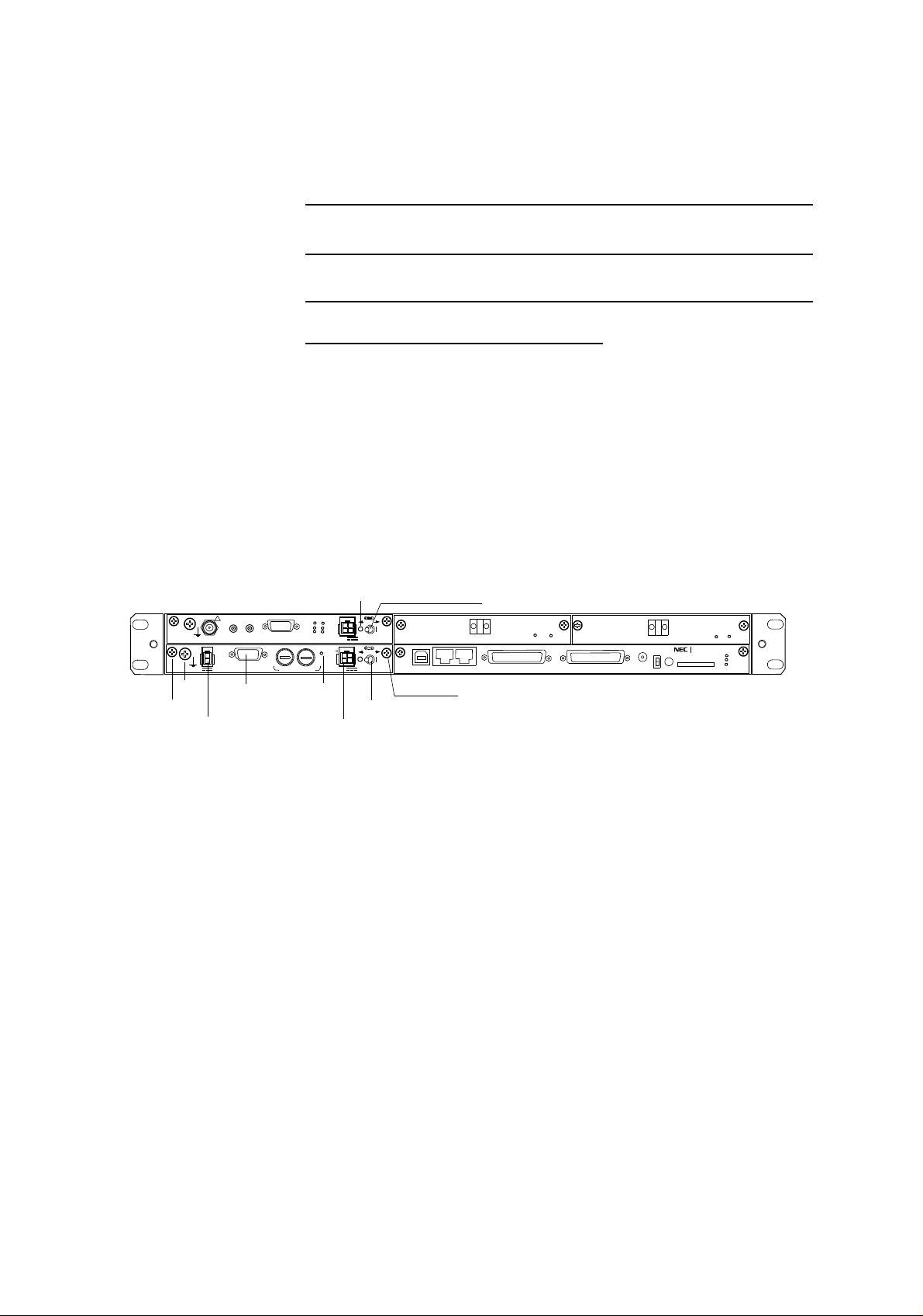
When the power is supplied to the SELV of the DC-DC CONV (optional)
but the PWR LED of the DC-DC CONV is not lit though the power switch
is on, before replacing the DC-DC CONV, check the conduction of the
fuse in the DC-DC CONV.
1 Referring to Chart 2-1, set the IDU to maintenance ON
condition by LCT
,
2 Set the power switch on the MODEM to Off position,
3 Set the power switch on the DC-DC CONV to Off position,
FG
Screw
!
−
43V
G
STD
OUT
G
−43V/OUT
IF IN/OUT
XIF IN
ALM
XIF OUT
ALM
TX
RX
XPIC
RESET
XPIC CTRL
FUSE (250V/8AH)
PWR LED
PWR LED
PWR
ODU
MD/
CBL
SELV
PWR
SELV
PULL
PWR
G
PULL
PWR Switch
LCT
PWR
OC-3 OUT
NMS
AUX/ALM
ONLINE
ALM
SC IN/OUT
OC-3 OUT
OC-3 IN
PROTECT
EOW
CALL
OC-3 IN
NE
NLITE E
MMC
ONLINE
MAINT
MEMORY
ALM
FG
IDU
Screw
PWR Switch
SELV
4 Disconnect cables connected to the DC-DC CONV as following
order,
(1) Disconnect power supply ca
(2) Disconnect power supply cable from
ble from SELV connector,
−43/OUT connector,
(3) Disconnect ground cable from ground terminal,
(4) Disconnect ALM cable from
ALM terminal,
5 Loosen two screws fixed the DC-DC CONV,
6 Extract the DC-DC CONV from the IDU shelf,
7 Check that the power switch on the spare DC-DC CONV is Off
position
8 Mount the spare DC-DC CONV to the IDU shelf,
9 Tighten two screws to fix the DC-DC CONV,
10 Connect cables to the DC-DC CONV as reversed order in step
4,
5-47
Page 49

CORRECTIVE MAINTENANCE ROI-S05751
Chart 5-4 (Cont’d)
Step Procedure
11 Turn on the power switch on the DC-DC CONV,
12 Check that PWR LED on the DC-DC CONV is on,
13 Turn on the power switch on the MODEM,
14 Check that PWR LED on the MODEM is on,
15 Check that ALM LED on the IDU is unlited,
16 Set the IDU to maintenance OFF condition by LCT.
5-48
Page 50

ROI-S05751 CORRECTIVE MAINTENANCE
Chart 5-4 (Cont’d)
Step Procedure
B. IDU REPLACEMENT
REMOVING
1 Turn off the power switch on the MODEM (both MODEM in
1+1 configuration),
2 Disconnect the IF cable, signal cables and the power cable, etc.
as following order,
(1) Disconnect XPIC CTRL cables from opposite IDU. (XPIC
configuration only.)
(2) Disconnect XIF coaxial cables from opposite IDU. (XPIC
configuration only.)
(3) Disconnect OC-3, LAN, Aux. signal cables from connector.
(4) Disconnect power supply cable from SELV connector.
(5) Disconnect IF cable from IF IN/OUT connector.
(6) Disconnect ground cable from the ground terminal
Note: The adapter for IF cable connector is reused.
3 As shown in Fig. 5-9, loosen four screws and remove the IDU,
MOUNTING
4 Fix the two brackets to desired position on the IDU, if necessary
(see Fig. 5-10),
5 Mount the IDU into the original position of the mounting rack
and tighten the four screws,
6 Reconnect the IF cables, signal cables and the power cable to
the original position as following order,
(1) Connect ground cable to the ground terminal
(2) Connect IF cable (with adapter) to IF IN/OUT connector.
(3) Connect power supply cable to SELV connector.
(4) Connect OC-3, LAN, Aux. signal cables to proper
connector.
(5) Connect XIF coaxial cables to opposite IDU. (XPIC
configuration only.)
(6) Connect XPIC CTRL cables to opposite IDU. (XPIC
configuration only.)
5-49
Page 51
CORRECTIVE MAINTENANCE ROI-S05751
Chart 5-4 (Cont’d)
Step Procedure
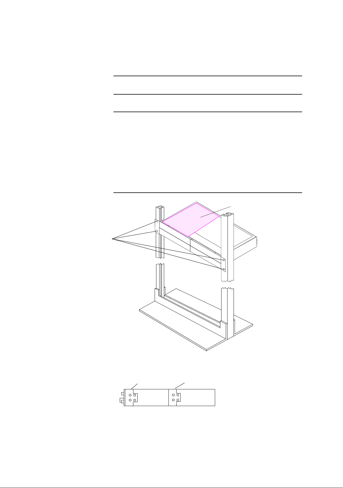
7 Form the wiring, and fix the cables using cable binder to the
mounting rack,
SCREW
Notes: 1. Do not cross the cables o
n front of indicators and power
switch used for maintenance.
2. Take suitable radius to wiring the IF cable. (e.g. 10DFB: 70 cm)
8 Turn on the power switch on the IDU.
Hot Surface
Note: Weight 4 kg.
Caution: The top surface of the IDU above
MODEM is hot in operation.
Fig. 5-9 Demounting and Remounting
FRONT
POSITION
Fig. 5-10 Bracket Mounting Position
5-50
CENTER
POSITION
SIDE VIEW
Page 52

ROI-S05751 CORRECTIVE MAINTENANCE
5.2.3 Fuse Replacement
When the power is supplied to the SELV but the IDU can not be powered
on with the power switch, check the conduction of fuse in the MODEM.
Chart 5-5 Fuse Replacement
Step Procedure
1 Set the power switch on the MODEM which is not powered to
Off position,
2 Disconnect cables connected to the MODEM as following
order,
(1) Disconnect power supply cable from SELV connector.
(2) Disconnect IF cable from IF IN/OUT connector. The adapter
is reused.
(3) Disconnect ground cable from the ground terminal.
3 Loosen two screws on the MODEM,
4 Extract the MODEM from the IDU shelf,
5 Remove protection cap over the fuse (see Fig. 5-11),
6 Remove the fuse from the fuse holder,
7 Check conduction of the broken fuse using tester,
8 Check conduction of the reserved fuse using tester,
9 Replace the broken fuse with reserved one,
10 Set the replaced fuse to the fuse holder,
11 Cap over the replaced fuse,
12 Mount the MODEM to the IDU shelf,
13 Tighten two screws on the MODEM,
14 Connect cables to the MODEM as reversed order in step 2,
15 Turn on the power switch on the MODEM,
16 Check that power is on.
5-51
Page 53
CORRECTIVE MAINTENANCE ROI-S05751
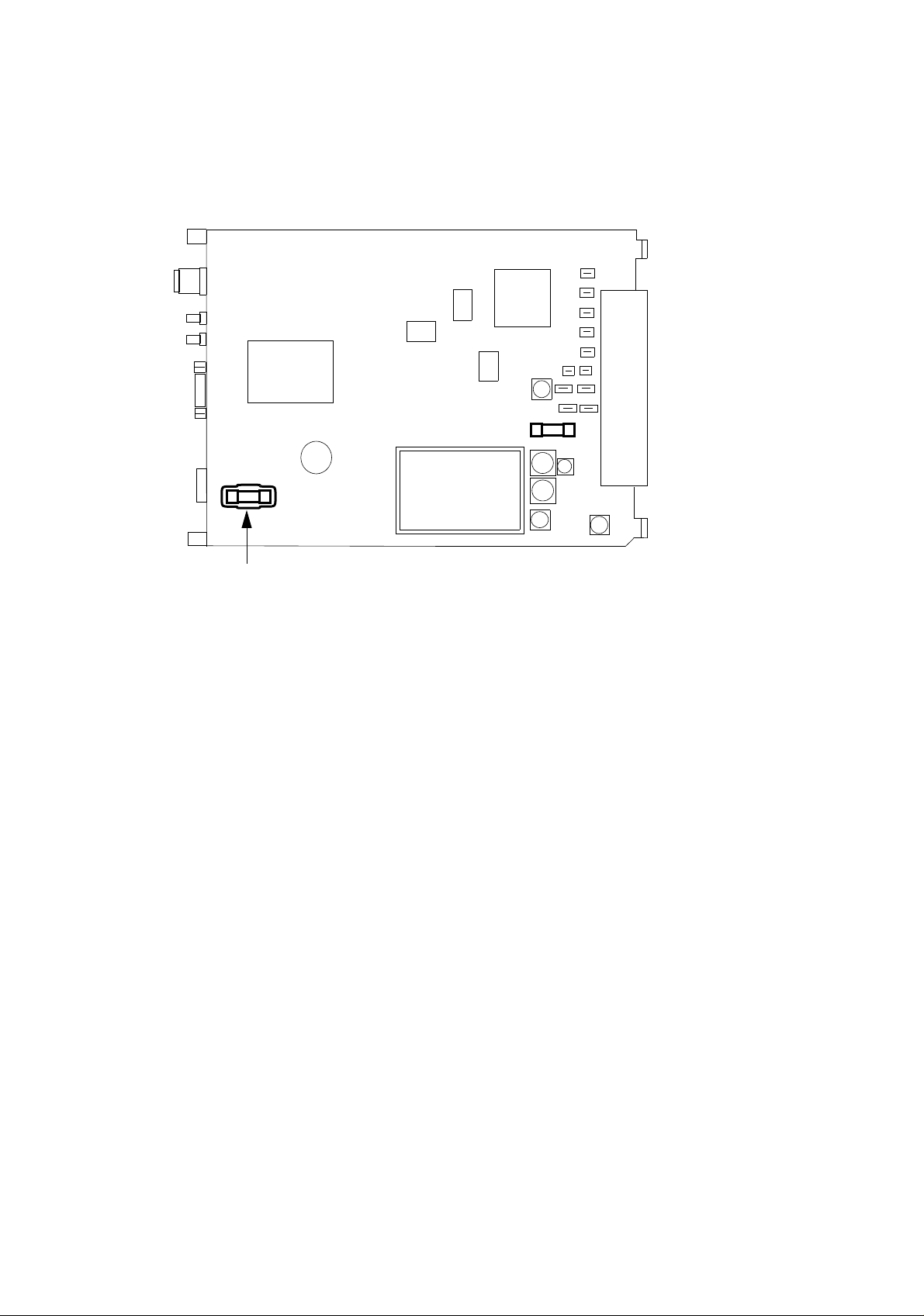
(MODEM)
(Front)
RESERVE
Reserve Fuse (6.3A)
21606.3 Fuse
RKS-F91000-0107
Fuse Cap
Fig. 5-11 Fuse in the MODEM
5-52
Page 54

ROI-S05751 CORRECTIVE MAINTENANCE
When the power is supplied to the SELV of the DC-DC CONV (optional)
but the PWR LED of the DC-DC CONV is not lit though the power switch
is on, check the conduction of the fuse in the DC-DC CONV.
Chart 5-6 DC-DC CONV Fuse Replacement
Step Procedure
1 Set the power switch on the DC-DC CONV which is not
powered to Off position
2 Disconnect cables connected to the DC-DC CONV as following
order,
(1) Disconnect power supply cable from SELV connector,
(2) Disconnect power supply cable from −43/OUT connector,
(3) Disconnect ground cable from ground terminal,
(4) Disconnect ALM cable from ALM terminal,
3 Loosen two screws on the DC-DC CONV,
4 Extract the DC-DC CONV from the unit,
5 Put the screwdriver to the groove of the fuse holder and turns
the fuse holder counter clockwise,
6 Remove the fuse from the fuse holder,
7 Check conduction of the broken fuse using tester,
8 Remove the reserved fuse as described in step 5,
9 Check conduction of the reserved fuse using tester,
10 Replace the broken fuse with reserved one,
11 Set the replaced fuse to the fuse holder,
12 Put the screwdriver to the groove of the fuse holder and push it
into the DC-DC CONV,
13 Turn the screwdriver clockwise until the fuse holder is locked
up, (When the fuse holder is locked up, the groove of the fuse
holder is set to horizontal as shown in Fig 5-12.)
14 Check and replace another fuse in the same way as from Step 5
to Step 13,
15 Mount the DC-DC CONV to the unit,
5-53
Page 55
CORRECTIVE MAINTENANCE ROI-S05751
Chart 5-6 (Cont’d)
Step Procedure
16 Tighten two screws on the DC-DC CONV,
17 Connect cables to the DC-DC CONV as reversed order in step
2,
18 Turn on the power switch on the DC-DC CONV,
19 Check that power is on.
20 Turn on the power switch on the IDU/DC-DC CONV UNIT,
21 Check that power is on.
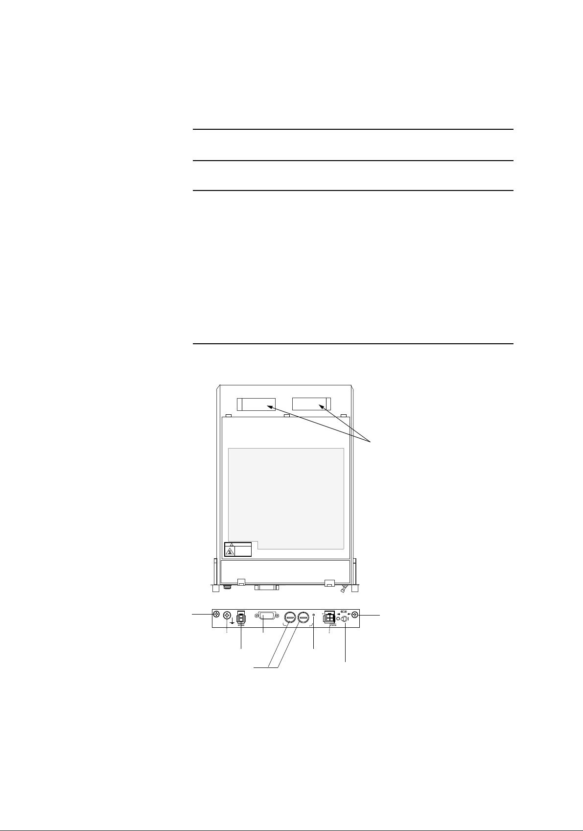
Screw
RESERVE
!
CAUTION
HOT SURFACE
Avoid contact.
STD
G
−43V/OUT
Fuse Holder
RESERVE
(DC-DC CONV)
−
43V
G
ALM
OUT
FUSE (250V/8AH)
ALM
PWR LED
(Front)
G
PULL
PWR
SELV
SELV
PWR Switch
Reserved Fuse
Reserve Fuse (8A)
GAB250V8 Fuse
CBE-006255-001
PWR
Screw
5-54
Fig. 5-12 Fuse in the DC-DC CONV
Page 56

ROI-S05749-05FE CONTENTS
August, 2007
NEC NLite E
6-38 GHz SONET DIGITAL RADIO SYSTEM
Section II OPERATION
CONTENTS
TITLE PAGE
1 GENERAL •••••••••••••••••••••••••••••••••••••••••••••••••••••••••••••• 1-1
2 OPERATING EQUIPMENT ••••••••••••••••••••••••••••••••••••••••• 2-1
2.1 IDU Shelf ••••••••••••••••••••••••••••••••••••••••••••••••••••••••••••2-4
2.2 CTRL ••••••••••••••••••••••••••••••••••••••••••••••••••••••••••••••••• 2-5
2.3 MODEM •••••••••••••••••••••••••••••••••••••••••••••••••••••••••••• 2-12
2.4 STM-1 INTFC ••••••••••••••••••••••••••••••••••••••••••••••••••••• 2-16
2.5 4P LAN INTFC (Optional) ••••••••••••••••••••••••••••••••••••• 2-18
2.6 GbE INTFC (Optional) •••••••••••••••••••••••••••••••••••••••••• 2-20
2.7 DC-DC CONV (Optional) •••••••••••••••••••••••••••••••••••••• 2-23
2.8 ODU ••••••••••••••••••••••••••••••••••••••••••••••••••••••••••••••••• 2-25
3 SYSTEM SETUP ••••••••••••••••••••••••••••••••••••••••••••••••••••••3-1
3.1 Equipment Setup ••••••••••••••••••••••••••••••••••••••••••••••••• 3-1
3.2 Provisioning Setup ••••••••••••••••••••••••••••••••••••••••••••••• 3-4
3.3 Events and Performance •••••••••••••••••••••••••••••••••••••••3-7
3.4 Control ••••••••••••••••••••••••••••••••••••••••••••••••••••••••••••• 3-14
3.5 Setup Description •••••••••••••••••••••••••••••••••••••••••••••• 3-16
3.5.1 Automatic Laser Shutdown Control
(OPT INTFC) (SDH) ••••••••••••••••••••••••••••••••••••••••••••• 3-16
3.5.2 Automatic Protection Switching (APS)
(OPT INTFC Optional APS Configuration) (SDH) ••••••• 3-18
3.5.3 Automatic Transmitter Power Control •••••••••••••••••••• 3-23
3.5.4 Loopback Control •••••••••••••••••••••••••••••••••••••••••••••• 3-27
3.5.5 Link Loss Forwarding Control (LAN) •••••••••••••••••••••• 3-27
3.5.6 MS-AIS Generation (SDH) •••••••••••••••••••••••••••••••••••• 3-28
3.5.7 Cross Polarization Interference Canceller (XPIC
Reset Control •••••••••••••••••••••••••••••••••••••••••••••••••••• 3-30
3.5.8 Network Management (Optional) ••••••••••••••••••••••••••• 3-31
CL-1
Page 57

CONTENTS ROI-S05749
TITLE PAGE
3.5.9 Functionality Classification ••••••••••••••••••••••••••••••••• 3-32
3.6 Protection Switching •••••••••••••••••••••••••••••••••••••••••• 3-33
3.6.1 1 + 1 Twin-path System ••••••••••••••••••••••••••••••••••••••• 3-33
3.6.2 Hot-standby System ••••••••••••••••••••••••••••••••••••••••••• 3-33
3.6.3 Switchover Control ••••••••••••••••••••••••••••••••••••••••••••• 3-34
CL-2
2 pages
Page 58

ROI-S05749-05FE CONTENTS
August, 2007
CL-3
Page 59

ROI-S05749 GENERAL
1. GENERAL
This section provides instructions for operation of the 6 to 38 GHz SONET
microwave radio system.
This section describes interface terminals and jacks, controls, indicators,
and test jacks. Use of the LCT is required for local operation, monitoring,
control and setup. For details of system and provisioning setup, refer to
Section IV NLite E LCT Manual.
1-1
Page 60
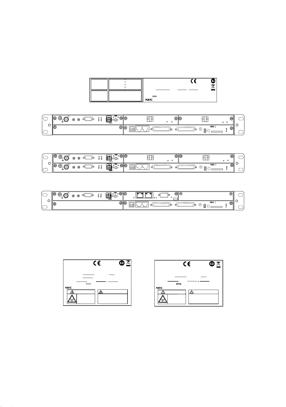
GENERAL ROI-S05749
NEC NLite E
OC-3 OUT
LCT
NMS
MDP-150MB-1AA
INDOOR UNIT
SER. No.
WEIGHT: 4 kg (WITH OPTION)
−48 V 2.5A (WITH ODU & OPTION)
NEC Corporation
OC-3 IN
NE
DATE ,
TOKYO JAPAN
ALM
ONLINE
AUX/ALM
SC IN/OUT
MODEM(1)
INTFC (1)
MODEM(2)
IF IN/OUT
!
XIF OUT
G
XIF IN
XPIC CTRL
RESET
TX
RX
XPIC
G
PWR
ODU
MD/
CBL
SELV
INTFC (2)
CTRL
PULL
PWR
(Blank)
IDU 1+0
IF IN/OUT
!
XIF OUT
G
!
XIF IN
IF IN/OUT
XIF IN
XIF OUT
XPIC CTRL
XPIC CTRL
RESET
RESET
TX
RX
XPIC
TX
RX
XPIC
G
PULL
PWR
ODU
MD/
CBL
PWR
SELV
G
PULL
PWR
ODU
MD/
CBL
PWR
SELV
LCT
OC-3 IN
OC-3 OUT
NMS
NE
ALM
ONLINE ONLINE
AUX/ALM
SC IN/OUT
IDU 1+1
0678
(H2930)
MADE IN JAPAN
OC-3 OUT
OC-3 IN
PROTECT
EOW
CALL
OC-3 OUT
PROTECT
EOW
CALL
OC-3 IN
ONLINE
NLite E NEO
MEMORY
MMC
NLite E NEO
MEMORY
MMC
MAINT
MAINT
ALM
G
IDU
ALM
G
IDU
IF IN/OUT
!
XIF OUT
G
XIF IN
XPIC CTRL
XPIC
RESET
RX
(Blank)
G
TX
PULL
PWR
ODU
MD/
CBL
PWR
SELV
100M
LCT
PORT 1 PORT 2
NMS
WS
100M
NE
AUX/ALM
WS IN/OUT
ALM
.
M S
SC IN/OUT
EOW
PROTECT
CALL
PASOLINK NEO
MAINT
MEMORY
IDU
MMC
G
Equipped with LAN Interface for Main LAN (SONET)
NEC NLite E
TRP-( )G-1B
OUTDOOR UNIT (NHG)
SHIFT FREQUENCY
TX FREQUENCY
SERIAL No.
WEIGHT 3.5kg/ - 48V
NEC Corporation TOKYO JAPAN
CAUTION
Non-ionizing
radiation
0678
MHz SUB BAND
MHz
DATE
0.5A
-48V INPUT
Power down IDU before
disconnection or
connection of cable.
(NWA-009034)
TX
HIGH/LOW
MADE IN JAPAN
NEC NLite E
TRP-( )G-1B
OUTDOOR UNIT (NHG)
SHIFT FREQUENCY
SERIAL No.
WEIGHT 3.5kg/ - 48V
NEC Corporation TOKYO JAPAN
CAUTION
Non-ionizing
radiation
0678
MHz SUB BAND
DATE
0.5A
-48V INPUT
Power down IDU before
disconnection or
connection of cable.
(NWA-009034)
TX
HIGH/LOW
MADE IN JAPAN
1-2
2 pages
Page 61

ROI-S05749 OPERATING EQUIPMENT
2. OPERATING EQUIPMENT
The indicators, switches, interface terminals and jacks for wiring with the
associated equipment are described here.
The IDU component modules listed in Table 2-1 are plugged-in from front
of the IDU shelf as shown in Fig. 2-1.
The component modules of the ODU shown in Fig. 2-2 are listed in Table
2-2.
Note: Use shielded cables which are connected to the RJ-45 connectors
to suppress interference from affecting the signal and to reduce
electromagnetic radiation which may interfere with other signal
cables.
Note:Twist power cables (+)/(−) to suppress inductive interference signals.
2-1
Page 62
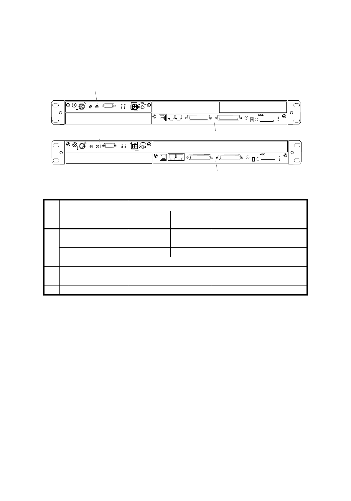
OPERATING EQUIPMENT ROI-S05749
1
IF IN/OUT
!
XIF OUT
G
XIF IN
XPIC CTRL
RESET
TX
RX
XPIC
2
G
PULL
PWR
ODU
MD/
CBL
PWR
SELV
LCT
NMS
4, or 5
NE
AUX/ALM
SC IN/OUT
EOW
PROTECT
5*
CALL
PASOLINK NEO
MAINT
MEMORY
IDU
MMC
G
1
IF IN/OUT
!
XPIC CTRL
RESET
XIF OUT
G
XIF IN
2
No. UNIT/MODULE NAME
MODEM
1
MODEM
2
DC-DC CONV
LAN INTFC
3
GbE INTFC
4
OC-3 INTFC
5
CTRL
6
G
TX
RX
XPIC
PULL
PWR
ODU
MD/
CBL
PWR
SELV
LCT
NMS
NE
Table 2-1 IDU COMPOSITION
H2930 MDP-150MB-1AA
Expandable
0 system
1 +
1 + 1 system
(X) (X)
−
(√) −
(√)
(√)
(√)
(X)
Notes: 1. (X) always equipped.
(√) optionally equipped.
2.
*1 selectable in setting program.
*2 for expanding power supply range
*3 for optional APS
(X)
6
3
AUX/ALM
SC IN/OUT
6
32QAM/128QAM *1
32QAM/128QAM *1
-20 to -60/+20 to +60 VDC *2
4-Port-LAN (for SONET) *3
GbE (for SONET)
OC-3 *3 for APS
PASO LINK NEO
PROTECT
EOW
CALL
MMC
REMARKS
.
MAINT
MEMORY
G
IDU
2-2
Fig. 2-1 IDU Composition
Page 63
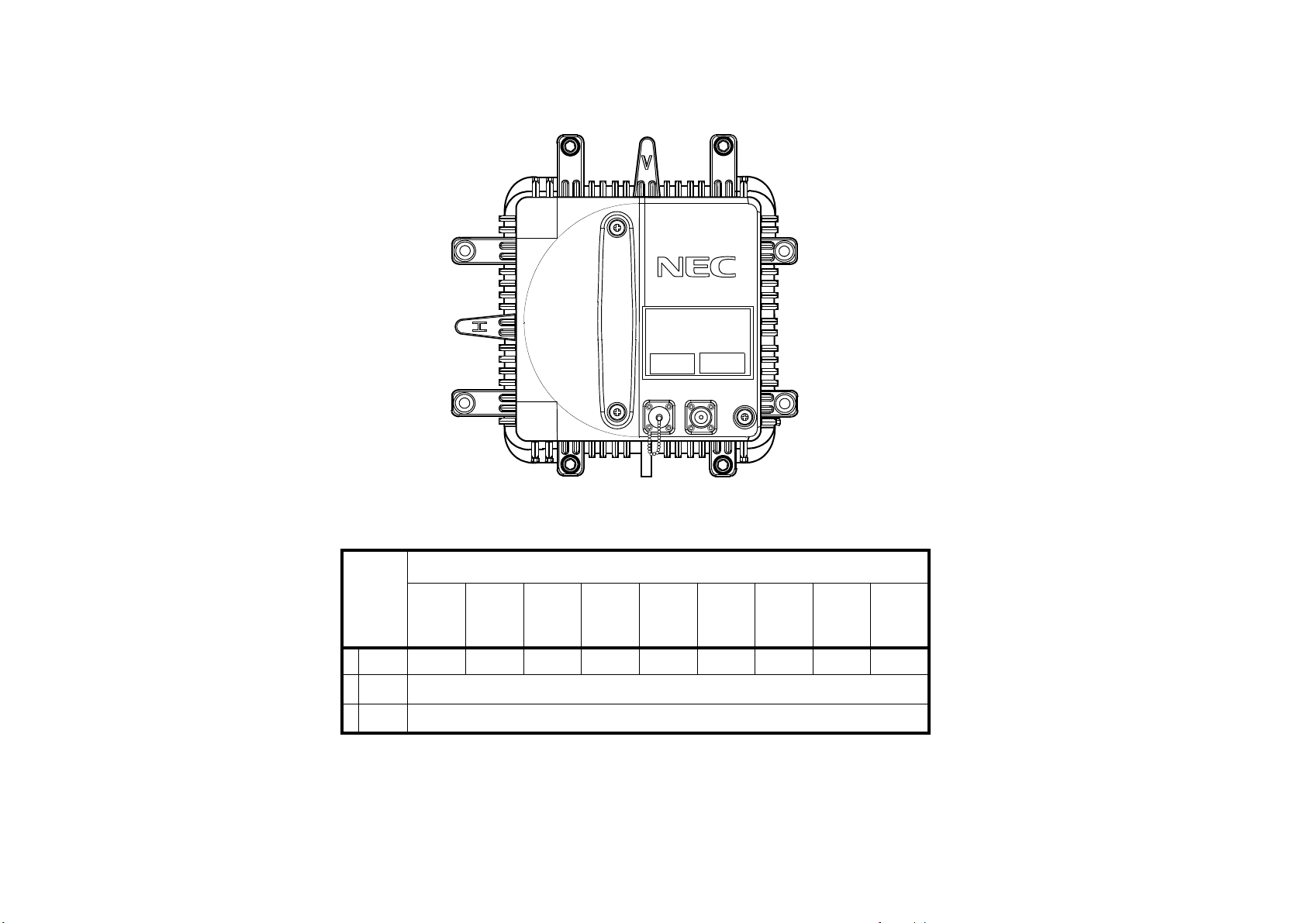
ROI-S05749 OPERATING EQUIPMENT
NLite E
2-3
RX LEV
MON
IFL
FG
6 - 38 GHz ODU
Table 2-2 ODU COMPOSITION
TRP-( )G-1B
MODULE
Name *
1 RF CKT H2202( ) H2203( ) H2204( ) H2225( ) H2205( ) H2229( ) H2230( ) H2231( ) H2234( )
2 IF CKT
3 PS
6 GHz 7 GHz) 8 GHz 10 GHz 11 G Hz 18 GHz 23 GHz 26 GHz 38 GHz
NWA-
009024( )
NWA-
009026( )
NWA-
009028( )
NWA-
009030( )
NWA-
009032( )
NWA-
009038( )
NWA-
009040( )
NWA-
009042( )
009048( )
—
—
Note: Component modules are enclosed in the ODU case.
Fig. 2-2 ODU Composition
NWA-
Page 64
OPERATING EQUIPMENT ROI-S05749
2.1 IDU Shelf
G
G
Jack (IDU)
G Electrostatic Discharge (ESD) jack used to connect
wrist strap band.
Caution*:Engineers for maintenance of the e
quipment must take the
necessary steps to avoid bit errors or cause damage to the
modules due to electrostatic discharge. Wear a conductive
wrist strap connected to the ground jack (G) on the front of
the IDU to minimize static build-up during maintenance.
G
G
*
2-4
Page 65
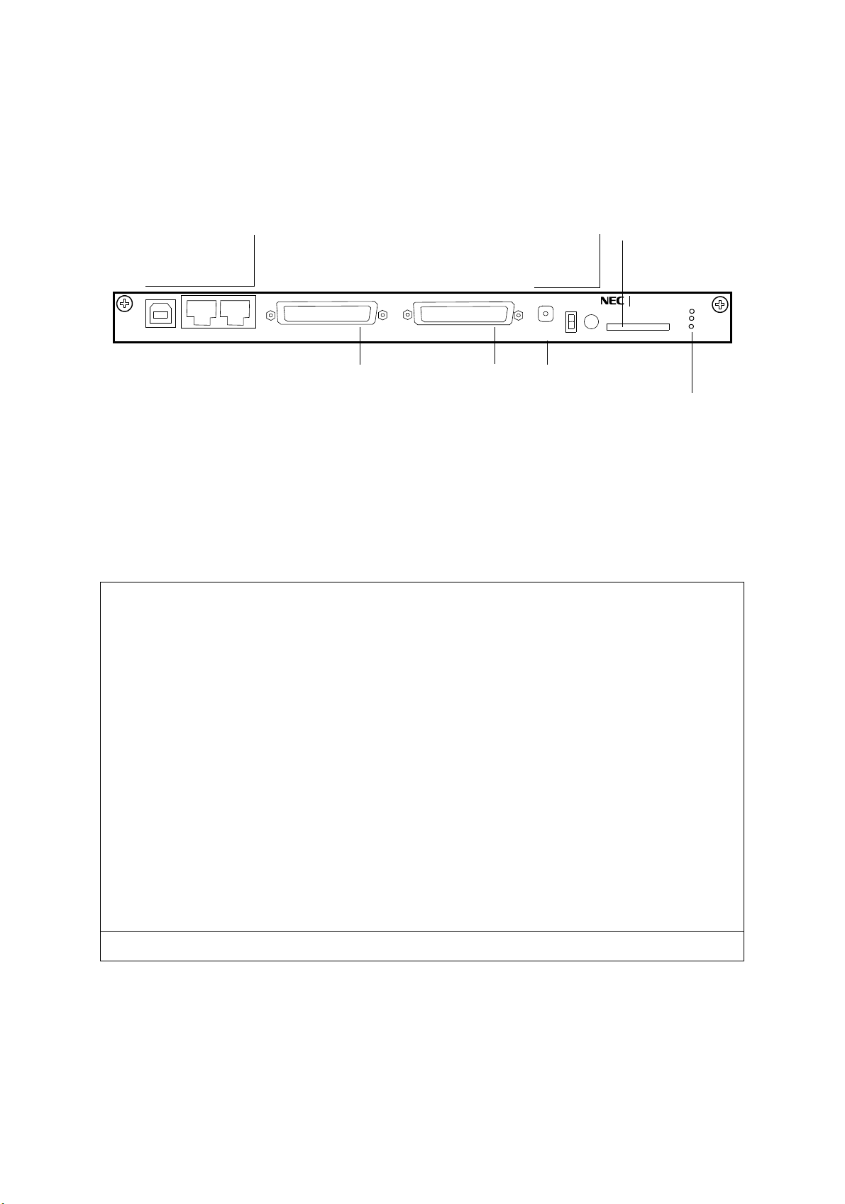
ROI-S05749 OPERATING EQUIPMENT
2.2 CTRL
LCT
NMS
AUX/ALM (D-Sub
Female 44 pins)
Input/Output Signal
NE
NMS
LCT
NE
AUX/ALM
AUX/ALM
SC IN/OUT
SC IN/OUT
PROTECT
EOW
EOW
CALL
PROTECT
CALL
MMC
PASOLINK NEO
MAINT
MEMORY
MMC
MAINT(amber)
MEMORY(amber)
IDU
IDU(red)
The CTRL generates various control signals based upon LCT setup data
and gathered operating status in the IDU and from the ODU, has SC,
EOW, LAN, NE, EXT ALM, HK, Cluster ALM signals interface. By
Connecting a PC, manual control, performance monitoring and system
setup can be performed.
Interface Signals (CTRL)
EOW: 1 CH
Frequency: 0.3 to 3.4 kHz (1020 Hz (Test Tone))
Level: −6 d
Bm
Impedance: 600 ohms
ALM: ALM 6 outputs/6 HK Inputs/ 4 HK Control outputs,
ster 4 Inputs/outputs
Clu
Output: Relay contact Form-C
Input: Photocoupler
Bz 1,2 IN: Signalling control extension input.
Call 1,2 OUT: Signalling control extension output.
EOW: EOW headphone jack
2-5
Page 66

OPERATING EQUIPMENT ROI-S05749
Interface Signals (CTRL)
SC IN/OUT (D-Sub
Female 44 pins)
Input/Output Signal
NE2: Network Element
Level: RS-485
DSC (RS-232C): 2 CH
Bit rate: 9600 bps
Level: RS-232C
DSC (V.11): 2 CH
Bit rate: 64 Kbps
Level: V. 1 1
Impedance: 100 ohms
NE (RJ-45): Network Element
Level: 10 Base-T
LCT (USB): Serial interface USB-B type connector with PC
NMS (RJ-45): PNMS
Level: 10 Base-T
Indicators (CTRL)
LED Indication Remarks
MAINT Maintenance mode can be
selected by LCT, PNMT and
PNMS
Actively blinks: In progress of program data download.
Inactively blinks:Protect Mode for CTRL replacement
in ef
fect.
“The maintenance Mode
N” is selected”.
“O
MEMORY Memory Card (MMC) status. ON: Enable access to Memory Card
OFF: Disable access to Memory Card
Blinks: Accessing Memory Card
IDU IDU Summary alarm. Check ALM LEDs on each module to find the cause
nd/or connect LCT to check the performance condition.
a
Blinks: CPU or peripheral event occurred.
2-6
Page 67
ROI-S05749 OPERATING EQUIPMENT
Switch (CTRL)
Switch Operating Remarks
CALL Transmits EOW calling signal to sound the
buzzer in the opposite station.
PROTECT Prevent service interruption when the CTRL
dule is replaced.
mo
User Interface Pin Assignment (CTRL)
Terminal Description
CTRL
ALM/AUX IN/OUT
Service channel data input/output
(D-sub Female, 44 Pins)
Pins 1 (+) and 16 (–) EOW input 1
Pins 2 (+) and 17 (–) EOW output 1
Pins 3 (+) and 18 (–) EOW input 2
Pins 4 (+) and 19 (–) EOW output 2
Pin 5 Ground
Pins 25 (COM), 40 (NC)
1 (NO) ⎯ RL1*1
and 1
Maintenance alarm output
Normal state : Closed Open
Alarm state : Open Closed
Accessing the Memory Card (MMC)
is required to apply the function.
Between Between
Pins 25 and 40 Pins 25 and 11
Pins 24 (COM), 39 (NC)
and 10 (NO) ⎯ RL2*1
Pins 23 (COM), 38 (NC)
and 9 (NO) ⎯ RL3
IDU CPU/PS1/PS2 alarm output
Between Between
Pins 24 and 39 Pins 24 and 10
Normal state : Closed Open
Alarm state : Open Closed
ODU1/ODU2 alarm output*2
Between Between
Pins 23 and 38 Pins 23 and 9
Normal state : Closed Open
Alarm/Event state : Open Closed
2-7
Page 68
OPERATING EQUIPMENT ROI-S05749
User Interface Pin Assignment (CTRL)
Terminal Description
Pins 22 (COM), 37 (NC)
ODU CPU1/ODU CPU2/Cable Open alarm output*2
and 8 (NO) ⎯ RL4
Normal state : Closed Open
Alarm/Event state : Open Closed
Pins 21 (COM), 36 (NC)
IDU total alarm output*2
and 7 (NO) ⎯ RL5
Normal state : Closed Open
Alarm/Event state : Open Closed
Pins 20 (COM), 35 (NC)
High BER1/High BER2 alarm output*2
and 6 (NO) ⎯ RL6
Normal state : Closed Open
Alarm/Event state : Open Closed
Pins 15 (+) and 14 (−) HK1 alarm input*3
Normal state : Open
Control/Event state : Closed
Pins 13 (+) and 12 (−) HK2 alarm input*3
Normal state : Open
Control/Event state : Closed
Between Between
Pins 22 and 37 Pins 22 and 8
Between Between
Pins 21 and 36 Pins 21 and 7
Between Between
Pins 20 and 35 Pins 20 and 6
Pins 29 (+) and 28 (−) HK3/Cluster4 alarm input*3
Normal state : Open
Control/Event state : Closed
Pins 27 (+) and 26 (−) HK4/Cluster3 alarm input*3
Normal state : Open
Control/Event state : Closed
Pins 44 (+) and 43 (−) HK5/Cluster2 alarm input*3
Normal state : Open
Control/Event state : Closed
Pins 42 (+) and 41 (−) HK6/Cluster1 alarm input*3
Normal state : Open
Control/Event state : Closed
Pin 30 Buzzer input 1
Pin 31 Call output 1
Pin 32 Buzzer input 2
Pin 33 Call output 2
2-8
Page 69

ROI-S05749 OPERATING EQUIPMENT
User Interface Pin Assignment (CTRL)
Terminal Description
CTRL
SC IN/OUT
(D-sub Female, 44 Pins)
Pins 1 (+) and 2 (–) NE2 TXD
Pin 3 Ground
Pins 4 (+) and 5 (–) V.11-1 TX data input
Pins 6 (+) and 7 (–) V.11-1 RX data output
Pins 8 (+) and 9 (–) V.11-2 TX data input
Pins 10 (+) and 11 (–) V.11-2 RX data output
Pins 12 and 13 (G) RS-232C-1 data input
Pins 14 and 15 (G) RS-232C-2 data input
Pin 16 NE2 RXD TERM
Pins 17, 18 Ground
Pins 19 (+) and 20 (–) V.11-1 TX clock input (co-dir.) or output (contra-dir.) *4
Pins 21 (+) and 22 (–) V.11-1 RX clock output
Pins 23 (+) and 24 (–) V.11-2 TX clock input (co-dir.) or output (contra-dir.) 4*
NE2/DSC Service channel data input/output
Pins 25 (+) and 26 (–) V.11-2 RX clock output
Pins 27, 28, 29 Ground
Pins 30 (+) and 31 (–) NE2 RXD
Pin 32 Ground
Pins 33 (+) and 34 (–) V.11-1 TX frame pulse input (co-dir.) or output (contra-dir.) *4
Pins 35 (+) and 36 (–) V.11-1 RX frame pulse output
Pins 37 (+) and 38 (–) V.11-2 TX frame pulse input (co-dir.) or output (contra-dir.) *4
Pins 39 (+) and 40 (–) V.11-2 RX frame pulse output
Pins 41 and 42 (G) RS-232C-1 data output
Pins 43 and 44 (G) RS-232C-2 data output
2-9
Page 70

OPERATING EQUIPMENT ROI-S05749
User Interface Pin Assignment (CTRL)
Terminal Description
LCT
Local craft terminal (LCT) data input/output
(USB connector type B)
Pin 1 Vbus
Pins 2 (–) and 3 (+) D
Pin 4 Ground
NMS (RJ-45) PNMS data (10Base-T) input/output
Pins 1 (+) and 2 (–) NMS TXD
Pins 3 (+) and 6 (–) NMS RXD
Pins 4, 5, 7 and 8 Not Connected
NE (RJ-45) NE data (10Base-T) input/output
Pins 1 (+) and 2 (–) NMS TXD
Pins 3 (+) and 6 (–) NMS RXD
Pins 4, 5, 7 and 8 Not Connected
Notes: *1: RL1 (Maintenance) and RL2 (IDU CPU/PS1/PS2
ALM OUTUT) are fixed and can not be changed to
other items. The relay contact is rated at 0.2 A.
*2: These alarm items are assigned at the factory (default
setting) and can be changed by the LCT as shown in
Table 2-3 in Section 1 (Alarms may be selectively
assigned to RL3 to RL6).
*3: Photocoupler interface; resistance of open input
terminal is more than 200 kilo ohms. Closed input
terminal is less than 50 ohms.
*4: V11 interface for the TX clock and frame pulse input/
output depend on co-/contra-directional mode setting
in the LCT provisioning menu.
2-10
Page 71
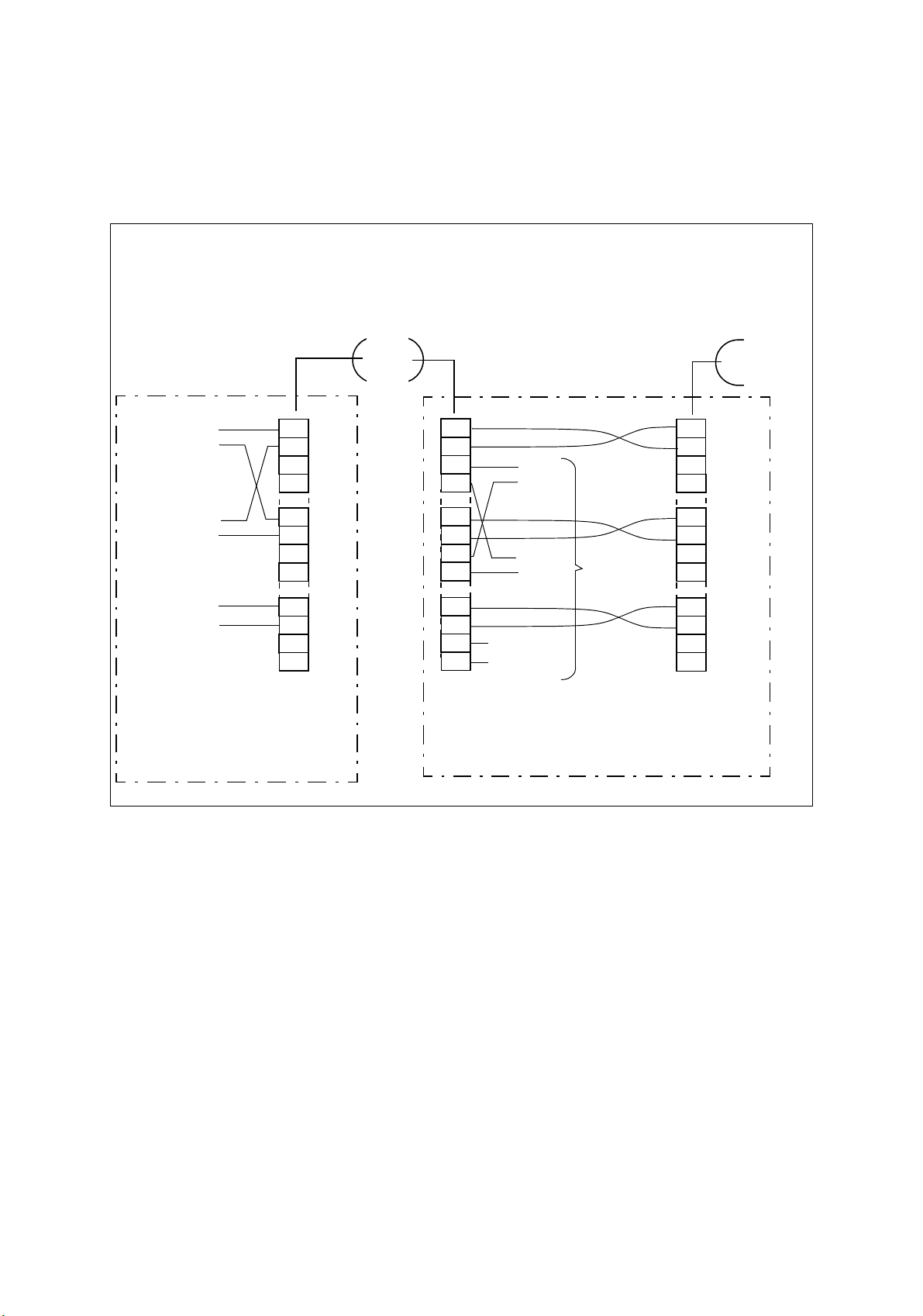
ROI-S05749 OPERATING EQUIPMENT
EOW Connection
When EOW signal is connected between two IDUs, perform wiring as follows.
Terminal Station A
EOW 4W S
EOW 4W R
Buzzer IN
Call OUT
ALM/AUX IN/OUT
(D-Sub, 44 Pins)
16
17
18
19
30
31
32
33
IDU Dir. B
Back -to- Back Station B
1
2
3
4
1
2
3
4
16
17
18
19
30
31
32
33
EOW
4W S
EOW
4W R
Buzzer IN
Call OUT
EOW
Extension
IDU Dir. A
ALM/AUX IN/OUT
(D-Sub, 44 Pins)
ALM/AUX IN/OUT
(D-Sub, 44 Pins)
1
2
3
4
16
17
18
19
30
31
32
33
IDU Dir. C
2-11
Page 72
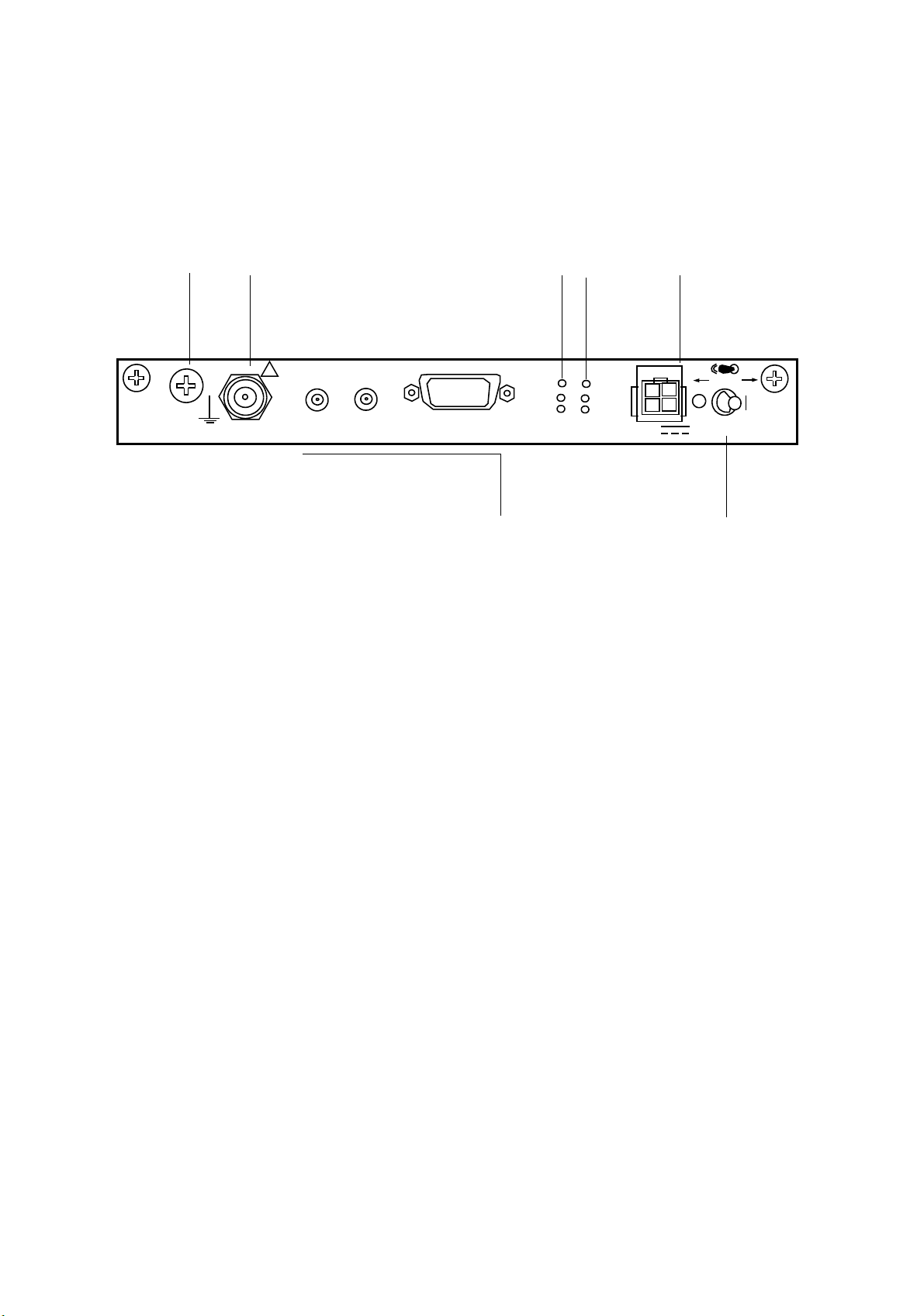
OPERATING EQUIPMENT ROI-S05749
2.3 MODEM
G
IF IN/OUT
IF IN/OUT
!
XIF IN
XIF OUT
XPIC RESET(amber)
XPIC CTRL
XPIC CTRL
XIF OUT
XIF IN
TX (green)
RX (green)
TX
RX
XPIC
RESET
PWR(green)
ODU(red)
MD/CBL(red)
PWR
ODU
MD/
CBL
SELV
SELV
PULL
PWR
PWR
Caution: Do not apply to the equipment a voltage that varies sharply. The equipment
operation may be impaired.
Caution: Do not remove/connect the IF cable with the IDU power ON, Turn the IDU
power OFF before connecting/disconnecting the IF cable, or equipment may
cause damaged.
Caution: Do not insert/extract the MODEM with the power ON, turn the IDU power
OFF and remove all cables connected to the MODEM before insert/extract the
MODEM, or MODEM may be damaged.
Caution: The top surface of the IDU shelf above MODEM is hot in operation.
The MODEM provides the 32QAM/128QAM Modulation/Demodulation
for, 10/100Base T(x)/1000 Base T (LAN) or OC-3 (SONET) data
transmission and following main functions.
- Forward Error Correction using RS/Interleave
- BER (High BER/Low BER) detection/indication/release for internal
d external
an
- Reducing ODU output signal distortion using BB Linearizer
- Equalization using Transversal Equalizer
- XPIC ODU synthesizer s
ynchronization control
- Interfered signal from opposite polarization cancellation (XPIC)
- IDU/ODU power supply
- System power on/off
2-12
Page 73

ROI-S05749 OPERATING EQUIPMENT
Interface Signals (MODEM)
IF IN/OUT (TNC Female)
TX Frequency: 340 MHz
RX Frequency: 140 MHz
Power supply: −48
V
Impedance: 50 ohms
Connecting IF Cable length:
5D-FB: less than 150 m
8D-FB: less than 300 m
10D-FB: less than 350 m
G (Screw): Ground terminal
(5 mm square cable (more than 2.5 mm diameter
ble) (AWG#10) is recommended to apply for the
ca
frame ground. The proper press fix terminal tool
shall be used.)
SELV (Molex M5569-04A1,
4 pins) (DC IN)
Input Voltage: −48 V DC
XIF IN/XIF OUT
Only used for XPIC system between two IDUs
(negative), + (positive, ground)
(Receptacle IEC 169-13 (1.0/
))
2.3
XIF IN: IF signal of opposite polari
(connect to XIF OUT of the other MODEM)
zation input.
XIF OUT: IF signal for opposite polarization output.
(connect to XIF IN of the other MODEM)
Frequency: 140 MHz
Impedance: 75 ohms
XPIC CTRL
(D-Sub 15 pins, Serial Port)
Automatic/Remote XPIC reset control signal inte
Only used for XPIC system between two IDUs
(connect to XPIC CTRL of the other MODEM)
rface between mutual MODEM.
2-13
Page 74
OPERATING EQUIPMENT ROI-S05749
Indicators (MODEM)
LED Indication Remarks
PWR The PWR switch of the MODEM is turned
on.
Transmit RF power of the ODU decreased
approx. −3 d
B from preadjusted ATPC
minimum (MIN) level in provisioning.
DC power is supplied to the
ODU also.
Check Metering using LCT for
local and/or opposite site in
Maintenance menu
Receiver input level of the ODU falls below
squelch level.
ODU
APC loop of local oscillator in ODU is
locked.
un
IF signal from the MODEM to ODU is lost.
Blinks when IF cable is open circuit.
Connected ODU is not matched with
ventory.
in
MD/CBL Blinks when IF cable is short circuit.
TX (only 1+1) Selected status of ODU TX When TX mute control: LED
f
Of
RX (only 1+1) Selected status of MODEM RX output signal When RX SWO switched to
posite: LED Off
op
XPIC RESET XPIC function is OFF condition Only XPIC configuration.
Propagation condition
deteriorated or XPIC is rese
t
from LCT control.
Switches (MODEM)
Switch Operating Remarks
PWR IDU and ODU power On/Off switch. Refer to Start-up and Shut-down the
Equipment in Maintenance Section
2-14
Page 75

ROI-S05749 OPERATING EQUIPMENT
User Interface Pin Assignment (MODEM)
Terminal Description
SELV
SELV (DC IN)
(Molex M5569-04A1 Connector,
−48 V DC power input
Note: Only −48
V (−40.5 to −57 V) is available.
4 Pins)
Pins 1 and 3 Ground
Pins 2 and 4 −48
V
IF IN/OUT
TNC Jack (Female) * IF signal IN/OUT and PS OUT to the ODU
XPIC CTRL
(D-Sub Female, 15 pins) Used for interconnection between IDUs in XPIC
configuration.
Pins 1 (+) and 6 (–) XPIC SV TXD
Pins 2 (+) and 7 (–) XPIC SV RXD
Pin 3 Ground
Pins 4 (+) and 9 (–) XPIC SEL IN
Pins 5 (+) and 10 (–) XPIC SEL OUT
Pins 8 (+) and 12 (–) XPIC RESET IN
Pin 11 Ground
Pins 13 (–) and 14 (+) XPIC RESET OUT
Pin 15 Ground
Note: * It is recommended that TNC (Male) L-angle connector for
the 8D-FB IF cable is used to connect it to the IDU. When
the N (Male) straight connector is attached to the 5D-FB or
10D-FB IF cable, use of the TNC (Male) - N (Female) (NJTNCP-LA) L-angle adapter is needed.
2-15
Page 76
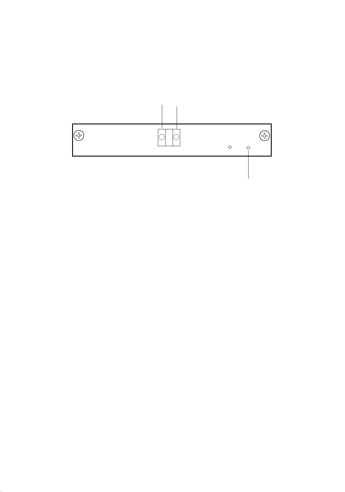
OPERATING EQUIPMENT ROI-S05749
2.4 OC-3 OPTICAL INTFC
STM-1 (OPT) INTFC
STM-1 OUT
STM-1 OUT
STM-1 IN
STM-1 IN
ALM
ONLINE
ALM (red)
ONLINE(green)
Caution: Do not insert/extract the OC-3 INTFC with the power ON. Turn OFF the PWR switch
on the MODEM and remove all cables connected to the OC-3 INTFC before inserting/
extracting theOC-3 INTFC, or that INTFC may be damaged.
The OC-3 INTFC provides an optical signal interface only. The module
performs the following functions:
- Coded Mark Inversion (CMI) to Non Return to Zero (NRZ)
nversion
co
- Optical to Electrical conversion
- RSOH termination
- Stuffing control
- Hitless switching (for 1+1 configuration)
- Performance monitoring (con
forms to G.826/G.828)
- Automatic Laser Shut Down (ALS)
- Near End/Far End loopback
2-16
Page 77

ROI-S05749 OPERATING EQUIPMENT
Interface Signals (OC-3 INTFC)
OC-3 IN/OUT
Optical OC-3 Input/Output, G.957
LC
Optical
Type: G.9 5 7
Bit Rate: 155.520 Mbps
Level: L-1.1: 0 to −8 d
S-1.1: −8 to −15
Bm (TX)/−10 to −34 dBm (RX)
dBm (TX)/−8 to −28 dBm (RX)
Code: NRZ
Wavelength: 1310 nm
Indicators (OC-3 INTFC)
LED Indication Remarks
LOSS of OC-3 from MUX is detected. Check MUX and wiring.
Frame synchronization of input OC-3 signal
from MUX is
lost.
Check MUX and wiring.
BER (E-BER, DMR or MUX) is worse than
-3
to 10-5, selectable).
-5
to 10-9, selectable).
ALM
pre
set value (10
BER (SD, DMR or MUX) is worse than preset
lue (10
va
Frame synchronization of input OC-3 signal
adio is lost.
from r
Mounting module is not matched with
ventory.
in
ONLINE Online status of Working/Standby in APS: ON
Offline status of Working/Standby in APS: OFF
Online status of Working w/o APS: ON
Check RSL, Interference and TX
power at
opposite site when BER
ALM occurs.
Check OC-3 transmission at the
opposite site, ODU or MODEM in
local.
Change LCT setting or other
( )INTFC module.
2-17
Page 78
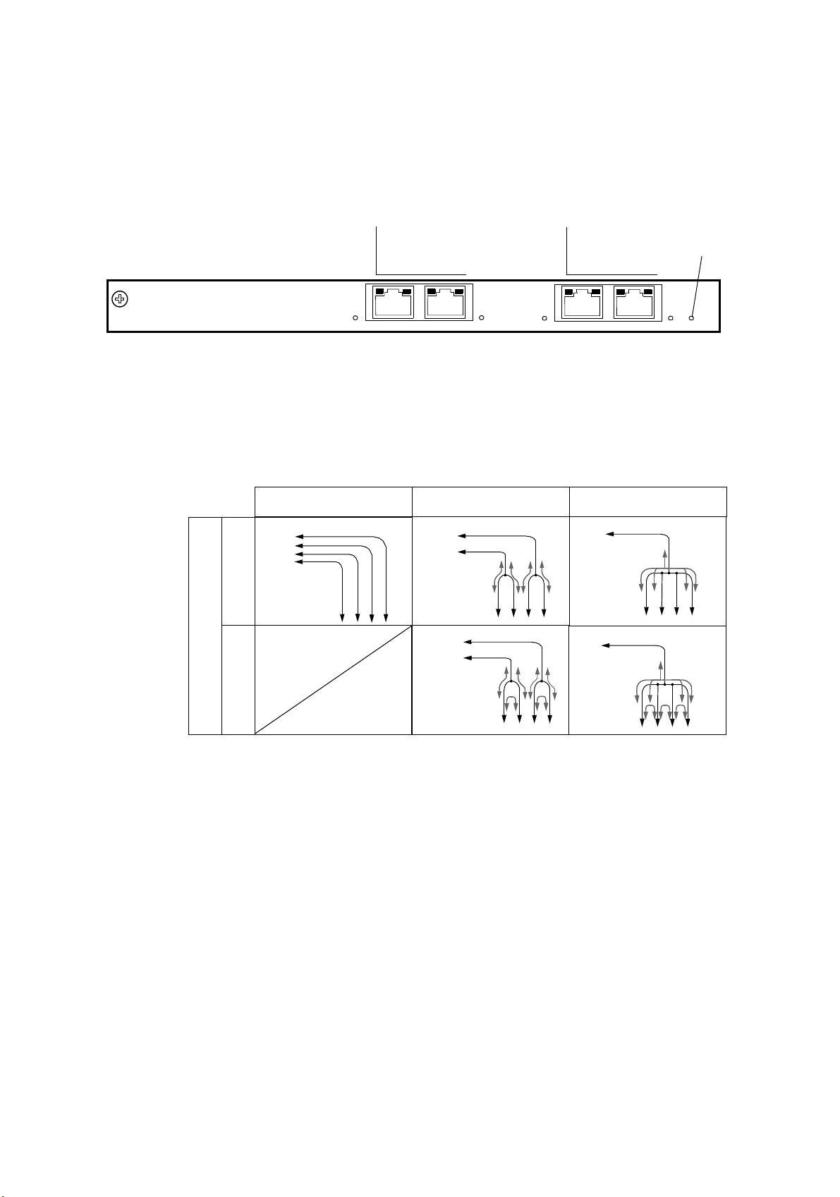
OPERATING EQUIPMENT ROI-S05749
2.5 4P LAN INTFC
4P LAN
PORT1
PORT2
PORT 1 PORT 2
100M
100M
100M
PORT3
PORT4
PORT 3 PORT4
ALM
LED(red)
ALM
100M
4P LAN INTFC
The 4P LAN INTFC (optional) is installed into the Main-INTFC slot
(Slot1) in the system configuration and it provides 4 Port LAN Fast
rnet interfaces. The LAN interface is used 4 Port shared (P1-P4)
Ethe
mode, 2 Port (P1-P
2/P3-P4) shared mode or separated (P1/P2/P3/P4)
mode.
Separated
(1)
Dir-A
Disabled
P3
P1
P2
P4
Switching
P1-P2 Shared
P3-P4 Shared
(2)
Dir-A
(4)
Dir-A
P1-P4 Shared
(3)
Dir-A
P3
P1
P2
P4
(5)
P1P2P3
Dir-A
P4
Enabled
P1P2P3
P4
P3
P1
P2
P4
2-18
Page 79
ROI-S05749 OPERATING EQUIPMENT
User Interface Signals (4P LAN INTFC)
LAN PORT1 to
PORT4 (RJ-45)
LAN interface Port 1, Port 2, Port 3 and Port 4.
Selectable 2 Mbps to 100 Mbps CH is assigned for LAN.
Input/Output Signal: 10/100Base-T(x) Auto-sensing or fixed
Flow control: Full duplex or Half duplex
Forwarding mode: Store-and-Forwarding
Indicators (4P LAN INTFC)
LED Indication Remarks
100M LAN signal is in 100BASE-TX mode.
LINK LAN and associated equipment are linked
nd flashing under the exchanging the
a
packet.
COLLISION/
DUPLEX
Input/Output LAN signal is in Full
Duplex mode.
Flashing when a collision
condition occurs.
ALM
The module is extracted. Mount the module.
Mounting module is not matched with
ventory.
in
Change LCT setting or other ( )INTFC
module.
LAN link failure occurs. Check LAN cable connection.
Module failure occurs. Replace the module with a spare.
2-19
Page 80
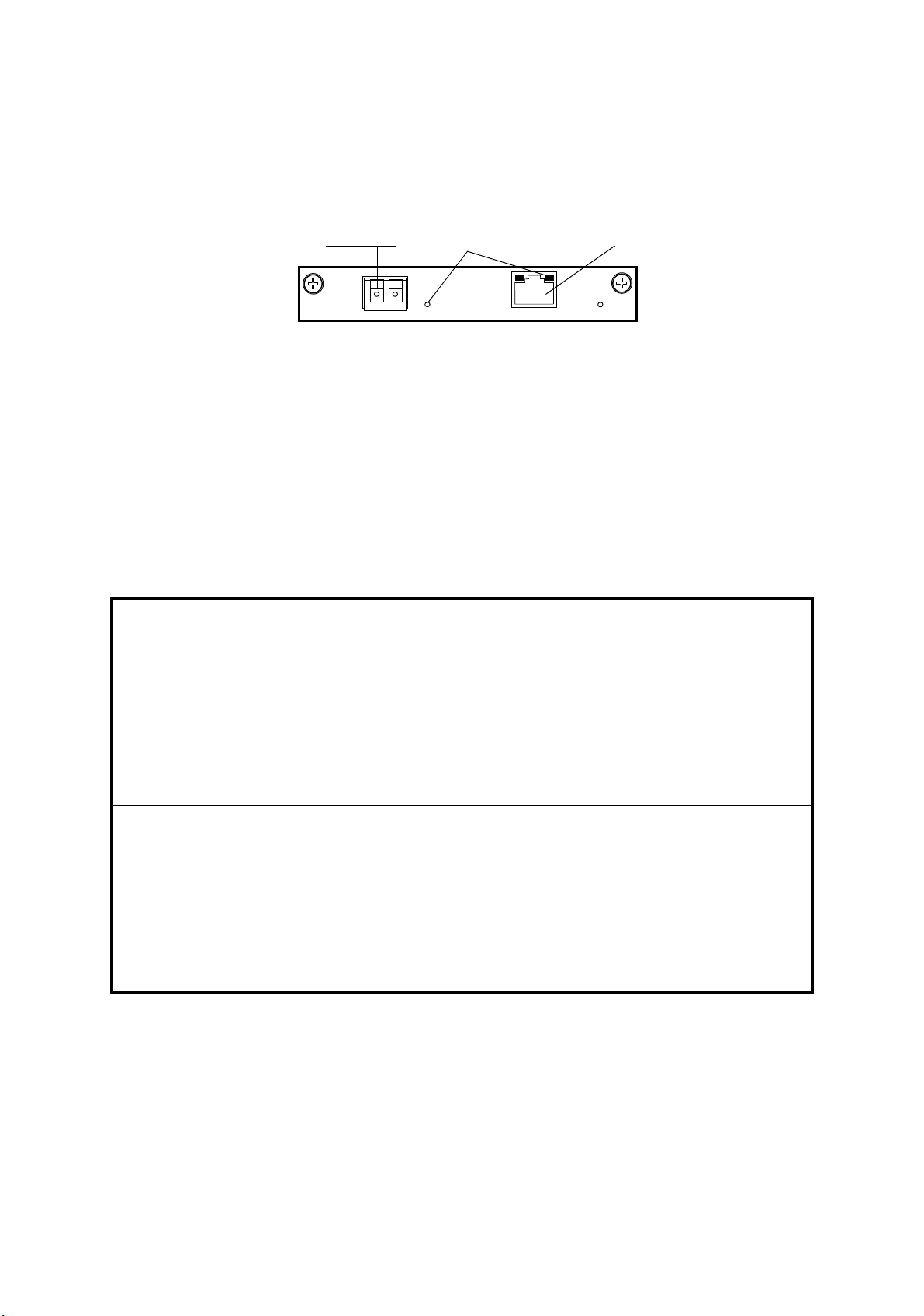
OPERATING EQUIPMENT ROI-S05749
2.6 GbE INTFC
1000BASE-SX
1000BASE-SX
OUT
INDICATOR
IN
The GbE INTFC (optional) provides 1000BASE-SX/1000BASE-T
interface. The GbE INTFC is installed into the Main-INTFC slot (Slot1)
instead of the OC-3 INTFC in the SONET (128 QAM) system
figuration. The signal is connected either SFP (for 1000BASE-SX) or
con
RJ-45 (for 1000MASE-T).
These bytes (E1/F1/DCCr) are available between radio links. The RMON
LINE side is available but DMR side is unavailable. The maximum
for
passed packet size is 9600 bytes.
The GbE INTFC ia applicable together with the LAN INTFC.
1000BASE-T
ALM
PORT
User Interface Signals (GbE INTFC)
1000BASE-SX: Gigabit Ether signal, Optical Interface
1000BASE-SX IN:
1000BASE-SX OUT:
Ether signal Input
Ether signal Output
(SFP Optical Interface
ector)
Conn
Speed & Duplex: 1000 Mbits Full Duplex/Auto Negotiation fixed
Flow control: Flow control ON or OFF selectable
Link Loss
Disabled/Enabled selectable
Forwarding:
1000BASE-T: Gigabit Ether signal, Electrical Interface
1000BASE-T Port:
Ether signal Input/Output
(RJ-45 Interface
Conn
ector)
Speed & Duplex: 1000 Mbits Full Duplex/Auto Negotiation fixed
Flow control: Flow control ON or OFF selectable
Link Loss
Disabled/Enabled selectable
Forwarding:
2-20
Page 81

ROI-S05749 OPERATING EQUIPMENT
User Interface Pin Assignment (GbE INTFC)
Terminal Description
1000BASE-SX
Multimode Fiber/LC Connector
(SFP Fiber connector)
IN (Right side) 1000BASE-SX Input
OUT (Left side) 1000BASE-SX Output
1000BASE-T
(RJ-45, 8 pins)
Pin 1 DATA-A
Pin 2 DATA-A
Pin 3 DATA-B
Pin 4 DATA-C
Pin 5 DATA-C
Pin 6 DATA-B
Pin 7 DATA-D
Pin 8 DATA-D
1000BASE-T Input/Output
(MDI/MDI-X)
+
/ DATA-B
−
/ DATA-B
+
/ DATA-A+
+
/ DATA-D+
−
/ DATA-D
−
/ DATA-A
+
/ DATA-C
−
/ DATA-C
+
−
−
+
+
−
Note: Cable connector: CAT5e/RJ-45
2-21
Page 82
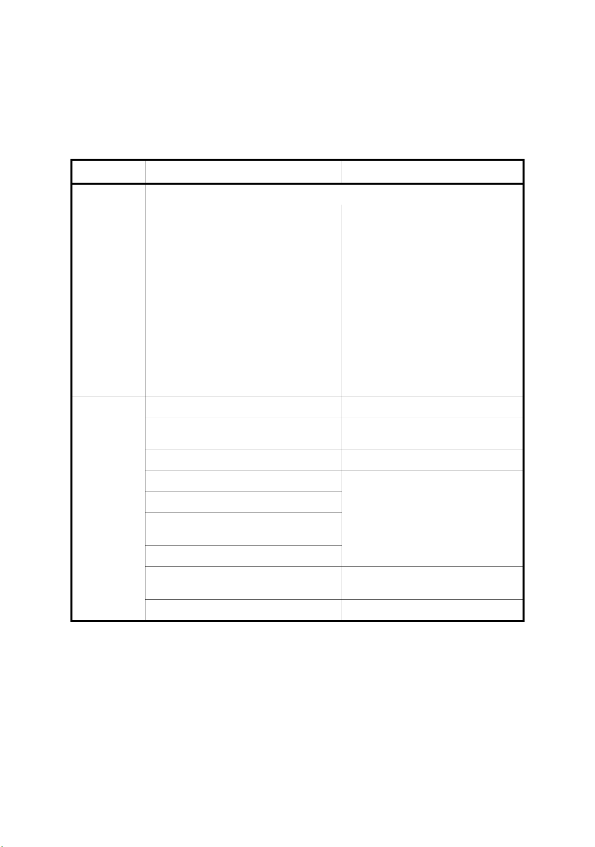
OPERATING EQUIPMENT ROI-S05749
Indicators (GbE INTFC)
LED Indication Remarks
Indicator Indicates which Port is applied to the signal interface.
When the indicator is flashing slowly, the
input si
interface port which is set to be used.
When the indicator is flashing fast, the
input/output signal is on in the
corresponding interface port
to be used.
When the indicator is lit steady, the signal
is linked in the corresponding interface
port
When the indicator is unlit, the
corresponding interface which port is
to no use.
gnal is off in the corresponding
which is set
which is set to be used.
set
ALM
The module is extracted. Mount the module.
Mounting module is not matched with
ventory.
in
Change LCT setting or other ( )INTFC
module.
Module failure occurs. Replace the module with a spare.
LOS from DMR is detected.
LOF from DMR is detected.
Excessive-BER alarm condition from
Check IDU/ODU and radio link.
DMR occurs.
SD from DMR is detected.
GbE output signal for fiber cable is
interrupted.
Replace the module with a spare. (SFP
mode o
nly)
LAN link failure occurs. Check LAN cable connection.
2-22
Page 83
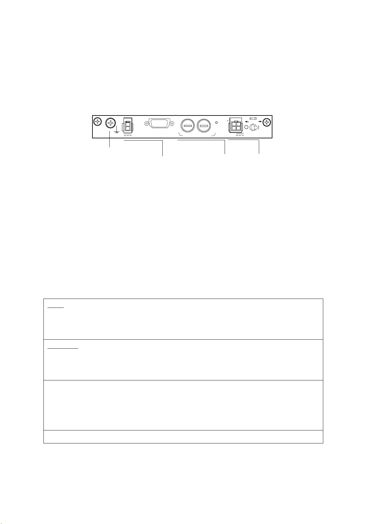
ROI-S05749 OPERATING EQUIPMENT
2.7 DC-DC CONV
DC-DC CONV
−
STD
43V
G
OUT
G
−
43V OUT
ALM
ALM
FUSE (250V/8AH)
PWR LED(green)
FUSE (250V/8AH)
PWR
Note: If the PWR LED is not lit though the PWR switch has set to ON, set the PWR switch to
OFF, remove two fuses from the module and check the conduction of them.
Caution: Do not apply to the equipment a voltage that varies sharply. The equipment
operation may be impaired.
Caution: Do not remove/connect the power supply cable with the PWR switch ON, Turn the
PWR switch OFF before connecting/disconnecting the power supply cable IN or
OUT, if not, module may be damaged.
SELV
+
PULL
PWR
PWR
SELV
The DC-DC CONV (optional) converts 20 to 60 V or −20 to −60 V DC
input to
−43 V stable DC voltage. The module applies when the Nlite E
ODU is connected to the IDU.
Interface Signals (DC-DC CONV)
SELV
(Molex M5569-04A1, 4 pins) (DC IN)
Input Voltage: −20
to −60 V/+20 to +60 V DC
−43V OUT
(Molex M5569-02A1,
2 pins) (DC OUT)
Output: −43
V/1.6A
G (Screw): Ground terminal
(5 mm square cable (more than 2.5 mm diameter cable)
WG#10) is recommended to apply for the frame
(A
ground. The proper press fix terminal tool shall be
used.)
+
ALM: Power supply ALM signal output
2-23
Page 84
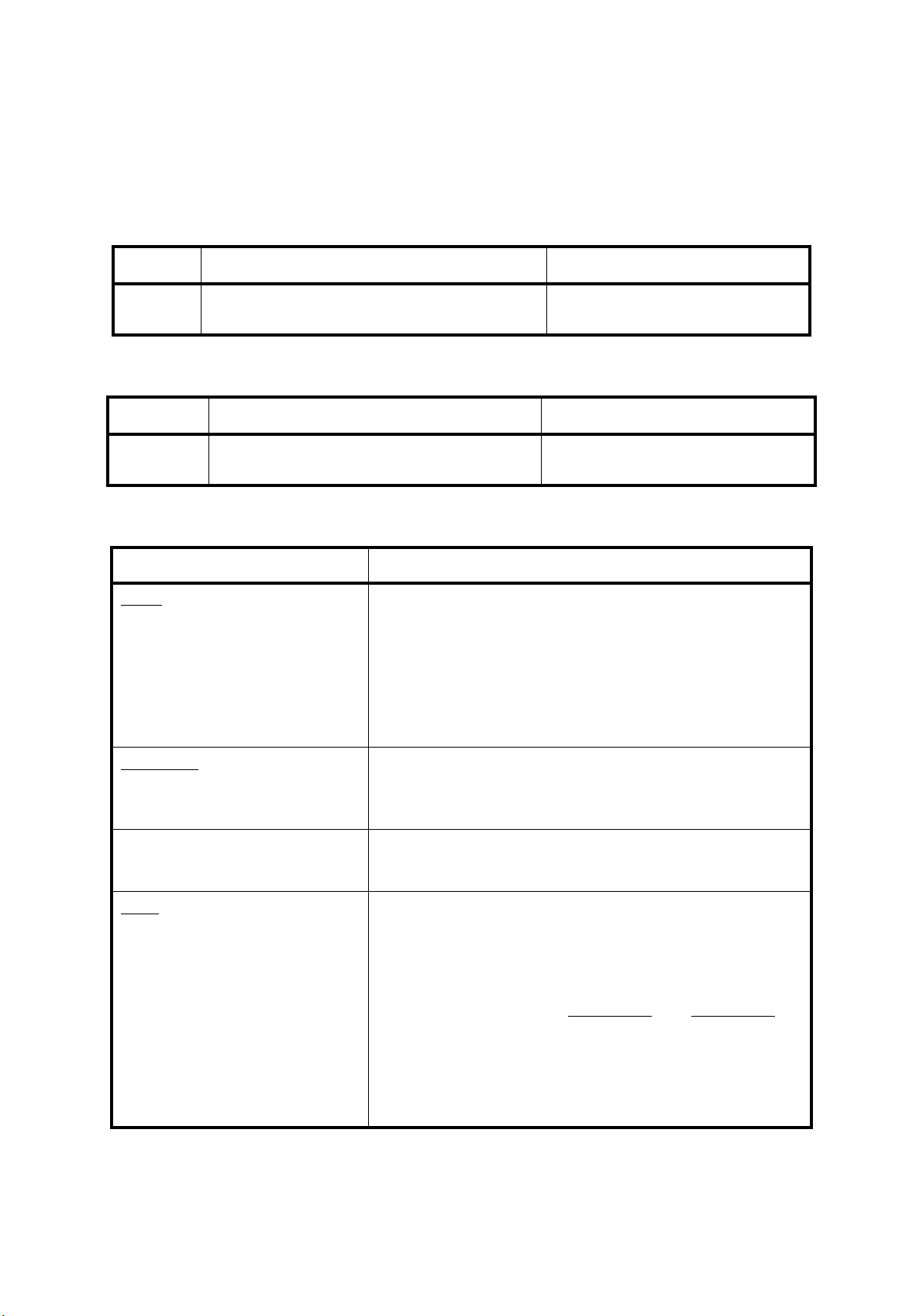
OPERATING EQUIPMENT ROI-S05749
Indicators (DC-DC CONV)
LED Indication Remarks
PWR The PWR switch of the DC-DC CONV is
turned on.
Switches (DC-DC CONV)
Switch Operating Remarks
PWR IDU and ODU power on/off switch. Refer to Start-up and Shut-down the
Equipment in Maintenance Section
User Interface Pin Assignment (DC-DC CONV)
Terminal Description
SELV
SELV (DC IN)
−20 to −60/20 to 60 V DC power input
(Molex M5569-04A1 Connector,
4 Pins)
Pins 1 and 3 0 V /(or +20 to +60 V)
Pins 2 and 4 −20
to −60 V/(or 0 V)
−43V OUT
(Molex M5569-02A1,
2 pins) (DC OUT)
−43
V DC power output (connects to the SELV connector of
the MODEM module using accessory cable)
Pin 1 Ground
Pin 2 −43
V
ALM Power supply ALM signal output
(D-Sub Female, 9 pins)
Pins 6 (COM), 1 (NC) and
)
2 (NO
PS and input voltage alarm output
Between Between
Pins 1 and 6 Pins 6 and 2
Normal state : Closed Open
Alarm state : Open Closed
2-24
Pin 9 Ground
Pins3,4,5,7,8 No connected
Page 85
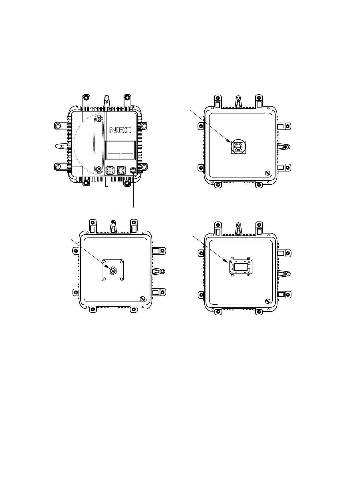
ROI-S05749 OPERATING EQUIPMENT
2.8 ODU
RF IN/OUT
NLite E
RX LEV
IFL
MON
FG
RF IN/OUT
(FRONT VIEW)
FG (Frame Ground)
RX LEV MON
(REAR VIEW)
IFL (IF IN/ OUT)
Coaxial Cable Type (6/7/8 GHz)
The ODU receives 340 MHz IF signal from the IDU and converts it to an
RF signal using a local signal generated by a synthesized local oscillator.
This RF signal is then sent to the antenna through the BPF which limits the
RF transmit signal dispersion. The TX output level is controlled to the
specified from the IDU corresponded to the QPSK 32QAM or 128QAM
modulation.
(REAR VIEW)
Antenna Direct Mounting Type
RF IN/OUT
(REAR VIEW)
WG Type (6/7/8 GHz)
The RF signal received from the antenna is
amplified to the required level.
Afterward the signal is converted into the 140 MHz IF signal by mixing
with a local signal generated by a synthesized local oscillator. Then the
140 MHz IF signal is sent to the IDU through the IF cable.
2-25
Page 86

OPERATING EQUIPMENT ROI-S05749
Interface Signals (ODU)
IFL (N Female)
TX Frequency 340 MHz
RX Frequency: 140 MHz
Power supply: −48
V
Impedance: 50 ohms
Connecting IF Cable length:
5D-FB: less than 150 m
8D-FB: less than 300 m
10D-FB: less than 350 m
FG (Screw) Frame ground, connecting near by ground point.
RF IN/OUT RF signal interface.
- N female connector for the 6/7/8 GHz ODU with coaxial
cable connection.
- NEC proprietary flange for the 10 to 38 GHz ODU with
enna mounting (direct/OMT/HYB COMB/TX ATT).
ant
- Waveguide connection flange;
6 GHz: PDR70
7/8 GHz: PDR84
10/11 GHz: PDR100
18/23 GHz: PBR220
38 GHz: PBR320
Monitoring Terminal (ODU)
Terminal Operating Remarks
RX LEV MON: Monitoring RX LEV in AGC voltage
using the digital voltmeter or PASOLINK
Use LCT to check the RX LEV in
Maintenance.
MONITOR unit * for antenna
orientation.
Note*:In order to measure exact performance of AGC V at the
RX LEV MON, it is mandatory r
Alignment Mode to ON as the AGC voltage indication is
not guaranteed outside Antenna Alignment Mode.
It is necessary to set to Antenna Alignment Mode every
time monitor the RX l
evel with the NLite E MONITOR
unit.
2-26
equired to set Antenna
Page 87

ROI-S05749 SYSTEM SETUP
3. SYSTEM SETUP
This section provides system setup to make up proper system
configuration. The setup is performed accessing to the LCT program using
the PC. For the detail procedure, refer to Section IV Appendix LCT
Operation Manual.
3.1 Equipment Setup
The equipment setup menu decides system fundamental configuration.
Note: For the details of setup item of the LAN PORT USAGE, refer to the
LAN INTERFACE (10/100BASE T(X)) Application and Setting in Section
IV.
3-1
Page 88

SYSTEM SETUP ROI-S05749
Equipment Setup for SONET
User Interface OC-3
GbE over OC-3
2Port LAN over OC-3
Redundancy Setting 1+0(TERM)
1+1(Hot Standby TERM)
1+1(Twinpath TERM)
INTFC Main (WORK) OC-3(Optical)
OC-3(Electrical)
GbE over OC-3 When the “SONET GbE over OC-3” is
2Port LAN over OC-3
INTFC SUB (PROT) Not Used
OC-3 (Optical)
WS
WS/LAN
XPIC Usage Not Used
Used (Main Master)
Used (SUB Master)
APS Function Unavailable
Available
Modulation Scheme 128QAM (fixed)
Transmission Capacity 156MB (fixed)
selected for User Interface.
TX RF Frequency(No.1) [MHz]
TX RF Frequency(No.2) [MHz]
RX RF Frequency(No.1) [MHz]
RX RF Frequency(No.2) [MHz]
Frame ID(No.1) (Up to #32)
Frame ID(No.2) (Up to #32)
TX Power Control MTPC
ATP C
LAN Port Usage (Main) USED (fixed when GbE INTFC is applied.)
LAN Capacity(Main) 150Mbps (fixed when GbE INTFC is applied.)
LAN Port Usage (Main) P1=75MB/P2=75MB (selectable when LAN INTFC is applied.)
P1=100MB/P2=50MB
Best Effort
P1=100MB/P2=Not Used
LAN Capacity(Main) 150Mbps (fixed when LAN INTFC is applied.)
LAN Port Usage (SUB) P1-2 Shared/1Port Only(WS)
P1-2 Shared/1Port Only(SC)
LAN Capacity(SUB) 64kbps
128kbps
192kbps
256kbps
2Mbps
3-2
Page 89

ROI-S05749 SYSTEM SETUP
Equipment Setup for SONET
---ODU FREQ INF--TX Start
Frequency(No.1) [MHz]
TX Stop Frequency(No.1) [MHz]
Frequency Step(No.1) [MHz]
Shift Frequency(No.1) [MHz]
Upper/Lower(No.1)
Sub Band(No.1)
TX Start
Frequency(No.2) [MHz]
TX Stop Frequency(No.2) [MHz]
Frequency Step(No.2) [MHz]
Shift Frequency(No.2) [MHz]
Upper/Lower(No.2)
Sub Band(No.2)
3-3
Page 90
SYSTEM SETUP ROI-S05749
3.2 Provisioning Setup
The provisioning setup menu determines system fundamental functions.
SONET Provisioning Setup
Provisioning
BER Threshold Setting High BER Threshold
Low BER/E BER(DMR)
SD(DMR)
E BER(MUX)
SD(MUX)
BER Threshold Setting High BER Threshold 1E-3 1E-4 1E-5
Low BER Threshold 1E-6 1E-7 1E-8 1E-9
E-BER (DMR) 1E-3 1E-4 1E-5
SD (DMR) 1E-6 1E-7 1E-8 1E-9
E-BER (MUX) 1E-3 1E-4 1E-5
SD (MUX) 1E-6 1E-7 1E-8 1E-9
SC Assignment RS-232C-1/2
V11-1/2
V-11-1/2 Direction Setting
LAN Port Setting
(For GbE INTFC)
LAN Port Setting
Switching Function Disable Enable
Port
Media Type SFP RJ-45
Speed & Duplex AUTONEG (1000MB Full Duplex).)
Flow Control Off On
Link Loss Forwarding Disabled Enabled
Not Used SC1 SC2 SC3 SC4
E1 (MUX)F1(MUX)E1(DMR)F1(DMR)
Not Used SC1 SC2 SC3 SC4
E1 (MUX) F1(MUX) DCCr(MUX) E1
(DMR) F1(DMR) DCCR(DMR) F1(DMR)
Co-directional Contra-directional
3-4
Page 91
ROI-S05749 SYSTEM SETUP
LAN Port Setting
(For LAN INTFC)
LAN Port Setting
(For LAN INTFC)
INTFC (Main) Setting
Switching Function
Clock Souce Setting Internal Clock DMR Internal -> Clock
Port1
Port Usage Not Used Used
Speed & Duplex AUTONEG (Auto-MDI/MDX)
10M-Half (MDI)
10M-Full (MDI)
100M-Half (MDI)
100M-Full (MDI)
10M-Half (MDIX)
10M-Full (MDIX)
100M-Half (MDIX)
100M-Full (MDIX)
Flow Control Off On
Collision Report Not Report Report
Port2
Port Usage Not Used Used
Speed & Duplex AUTONEG (Auto-MDI/MDX)
10M-Half (MDI)
10M-Full (MDI)
100M-Half (MDI)
100M-Full (MDI)
10M-Half (MDIX)
10M-Full (MDIX)
100M-Half (MDIX)
100M-Full (MDIX)
Flow Control Off On
Collision Report Not Report Report
Link Loss Forwarding Disabled Enabled
INTFC (SUB) Setting
Switching Function Disabled Enabled
Port1
Port Usage Not Used Used
Speed & Duplex AUTONEG (Auto-MDI/MDX)
10M-Half (MDI)
10M-Full (MDI)
100M-Half (MDI)
100M-Full (MDI)
10M-Half (MDIX)
10M-Full (MDIX)
100M-Half (MDIX)
100M-Full (MDIX)
Flow Control Off On
Collision Report Not Report Report
Link Loss Forwarding Disabled Enabled
Port2
(Items for Port 2 are same as the Port1)
3-5
Page 92

SYSTEM SETUP ROI-S05749
OC-3 Setting MS-AIS Generation Disabled Enabled
ALS ALS Function Disabled Enabled
ALS Interval 60sec 180sec 300sec
TX Power Control ATPC Threshold Level(No.1/2) [dBm]
Additional ATT(No.1/2 [dB]
ATPC Range(MAX)(No.1/2) [dB]
ATPC Range(MIN)(No.1/2) [dB]
ATPC Power Mode(No.1/2) HOLD Max MIN
MTPC TX Power (No.1/2) [dBm]
ATPC Threshold Level(No.1/2) [dBm]
Additional ATT(No.1/2) [dB]
Condition for TX/RX SW TX SW Priority
RX SW Priority
RX SW Maintenance Mode
RX SW Condition-Early Warning
Condition for APS APS Maintenance Mode
APS Condition-SF(PROT)
APS Condition-Signal Degrade-SD(B1)
Lock in Usage
Lock in Count [times]
Lock in Detect Time [min]
Lock in Hold Time [hours]
Relay Setting ALM output for RL1 to RL6
HK output for RL3 to RL6
Cluster1 to Cluster4 input
Cluster1 to Cluster4 output
TCN Threshold(15min) DMR/ OCR/RCVR
MUX OCR/RCVR
TCN Threshold(1day) DMR/ OCR/RCVR
MUX OCR/RCVR
PMON Select RX Level TCN Threshold [dBm]
SES Activation Condition
Others EOW2 External Setting
Alarm Correlation Capacity
Non-Priority Priority No.1
Non-Priority Priority No.1
Manual Forced
Included EW Excluded EW
Manual Forced
Priority High Priority Low
Included SD Excluded SD
Not Used Used
Out
HK
Disabled Enabled
Out
OFS
UAS
ES
SES
BBE
SEP
OFS
UAS
ES
SES
BBE
SEP
30[%] 15[%]
Normal Invert
Off On
3-6
Page 93

ROI-S05749 SYSTEM SETUP
3.3 Events and Performance
The alarm and status condition are based upon equipment setup and
provisioning setup, therefore indication items vary depending on the those
setup.
The summarized event and performance monitoring that are displayed on
the LCT PC are listed in the following table. For the detailed items, refer
to Section IV Appendix LCT OPERATION MANUAL.
3-7
Page 94

SYSTEM SETUP ROI-S05749
Event List SONET
Alarm Status
ODU
ODU
TX Power
TX Input
RX Level
APC
ODU CPU
Mute Status
LO REF : only XPIC configuration
TX SW Status : only 1+1 configuration
RX SW Status : only 1+1 configuration
MODEM
MODEM
MODEM Unequipped
LOF
Route ID
High BER
Low BER
Early Warning
MOD
DEM
Input Voltage
Power Supply
IF Cable Short
Linearizer Status
Linearizer Fail
Cable EQL
XIF
XCTRL : only XPIC configuration
XPIC Status
XREF
ATPC Power Mode
CTRL
CTRL Module
MMC Mount
APS SW Fail : only APS configuration
APS Online Status : only APS configuration
APS Lock in Status : only APS configuration
XCTRL : only XPIC configuration
XCTRL Mode Mismatch : only XPIC configuration
UAE
OC-3(1)/UAE(MUX)
OC-3(1)/UAE(DMR)
3-8
Page 95

ROI-S05749 SYSTEM SETUP
Event List SONET
INTFC (Main)
Unequipped
Type Mismatch
OC-3(1) LOS (MUX)
OC-3(1) LOS (DMR)
OC-3(1) LOF (MUX)
OC-3(1) LOF (DMR)
OC-3(1) Output Control
OC-3(1) E-BER (MUX)
OC-3(1) E-BER (DMR)
OC-3(1) SD (MUX)
OC-3(1) SD (DMR)
OC-3(1) In-Phase
OC-3(1) TF
INTFC (Main)
Unequipped
Type Mismatch
Module
LAN Link
Link Loss Forwarding
Speed & Duplex
LOS (DMR)
LOF (DMR)
E-BER (DMR)
SD DMR
Inphase
TF
GbE INTFC
3-9
Page 96

SYSTEM SETUP ROI-S05749
Event List SONET
INTFC (Sub)
INTFC(2) Unequipped
OC-3(2) LOS (MUX)
OC-3(2) E-BER (MUX)
OC-3(2) E-BER (DMR) OPT INTFC applies APS
OC-3(2) SD (MUX)
OC-3(2) SD (DMR)
OC-3(2) Output Control
OC-3(2) In-Phase
OC-3(2) LOS (DMR)
OC-3(2) LOF (MUX)
OC-3(2) LOF (DMR)
OC-3(2) TF
Unequipped
Type Mismatch
Module
LAN Link *1
LAN Collision *1 When LAN Port
Link Loss Forwarding *1
Speed & Duplex *1
TCN-RX LEV
TCN-RX LEV-15min
TCN-RX LEV-1day
3-10
Page 97

ROI-S05749 SYSTEM SETUP
Event List SONET
15min 1 day
TCN-OFS-15min Total
TCN-UAS-15min Total
TCN-ES-15min Total
TCN-SES-15min Total
TCN-BBE-15min Total
TCN-SEP-15min Total
TCN-OFS-15min(MUX)
TCN-UAS-15min(MUX)
TCN-ES-15min(MUX)
TCN-SES-15min(MUX)
TCN-BBE-15min(MUX)
TCN-SEP-15min(MUX)
TCN-OFS-15min(MUX)(P)
TCN-UAS-15min(MUX)(P)
TCN-ES-15min(MUX)(P) only APS configuration
TCN-SES-15min(MUX)(P)
TCN-BBE-15min(MUX)(P)
TCN-SEP-15min(MUX)(P)
TCN-OFS-1day Total
TCN-UAS-1day Total
TCN-ES-1day Total
TCN-SES-1day Total
TCN-BBE-1day Total
TCN-SEP-1day Total
TCN-OFS-1day(MUX)
TCN-UAS-1day(MUX)
TCN-ES-1day(MUX)
TCN-SES-1day(MUX)
TCN-BBE-1day(MUX)
TCN-SEP-1day(MUX)
TCN-OFS-1day(MUX)(P)
TCN-UAS-1day(MUX)(P)
TCN-ES-1day(MUX)(P)
TCN-SES-1day(MUX)(P) only APS configuration
TCN-BBE-1day(MUX)(P)
TCN-SEP-1day(MUX)(P)
3-11
Page 98

SYSTEM SETUP ROI-S05749
Event List SONET
PMON(History)
RX Level
RX Level(15min)
RX Level(1day)
DMR (W) (1day)
Status
OFS
SEP
BBE
ES
SES
UAS
DMR (W) (15min)
Status
OFS
SEP
BBE
ES
SES
UAS
MUX (W) (day)
Status
OFS
SEP
BBE
ES
SES
UAS
MUX (W) (15min)
Status
OFS
SEP
BBE
ES
SES
RMON(Line)(15min) only for LAN
Status
RX UNICAST
RX BROADCAST
RX MULTICAST
RX PAUSE
RX CEC ERR
RX ALIGNMENT ERR
RX SYMBOL ERR
RX UNDERSIZE
RX FRAGMENTS
RX Pkts 64
RX Pkts 65 to 127
RX Pkts 128 to 255
RX Pkts 256 to 511
3-12
Page 99
ROI-S05749 SYSTEM SETUP
Event List SONET
RX Pkts 512 to 1023
RX Pkts 1024 to 1536
TX JABBERS
TX UNICAST
TX BROADCAST
TX MULTICAST
TX PAUSE
TX COLLISION
Notes : *1 When the LAN/WS INTFC is provided, status of each LAN
PORT is displayed as follows.
Status of LAN PORT
Link Collision LLF Speed & Duplex
Sub PORT1 Link Normal Normal 100M-Full (MDIX)
Sub PORT1 Link Normal Normal 100M-Full (MDIX)
Notes:For the GbE INTFC, there are distinctions for the
following functions from the 10BASE-T/100BASE-Tx
1. RX Undersize: Unavailable.
2. RX Fragments: Unavailable.
3. RX Symbol Errors:
For SFP: Available
For RJ-45: Unavailable (un-counting, only "0" is
indicated.)
4. TX Multicast PKts (Including number of the TX pause
packets.)
5. RX Multicast PKts (Including number of the RX pause
packets.)
6. Countable packet size for the following items shown in
right side of the table and reading must be taken place
as follows. (The indication will not be taken placed.)
Indication Reading
15 RX Pkts 1024-1536 RX Pkts 1024-1518
16 RX Pkts 1537-MAX RX Pkts 1519-MAX
7. The RX Alignments Error is counted as an RX CRC
ERR.
3-13
Page 100

SYSTEM SETUP ROI-S05749
3.4 Control
The control condition is based upon equipment setup and provisioning
setup, therefore control items vary depending on the those setup.
The control items that are displayed on the LCT PC are listed in the
following table. the control operation can be performed in Maintenance
“ON”.
3-14
 Loading...