


User’s Manual
English
EXIT |
INPUT |
MUTE |
PlasmaSync 42XP10
PlasmaSync 50XP10
PlasmaSync 60XP10

Package Contents
•Plasma Monitor
•Remote control and AA Batteries •Power cord
•Users Manual (CD-ROM)
•Start Up Guide (Paper / CD-ROM)
•Main Power Switch cover and screw •Cable clamps

Table of Contents
Important Safety Instructions.............................................................................................................. |
English-1 |
Important Information ........................................................................................................................... |
English-2 |
Safety Precautions and Maintenance................................................................................................... |
English-3 |
Recommended Use.................................................................................................................................... |
English-4 |
Installation |
|
Using Optional Stands/Mounts............................................................................................... |
English-6 |
Mounting Location.................................................................................................................... |
English-6 |
Mounting on Ceiling.................................................................................................................. |
English-7 |
Maintenance, Orientation, Cable Management .................................................................. |
English-7 |
Using the Remote ...................................................................................................................... |
English-8 |
Part Names and Functions |
|
Control Panel.............................................................................................................................. |
English-9 |
Terminal Panel............................................................................................................................ |
English-10 |
Remote Control Functions....................................................................................................... |
English-11 |
Power, Display, Digital Zoom, Pointer, Main Power Switch Cover..................................... |
English-12 |
Remote Control ID..................................................................................................................... |
English-13 |
On-Screen Display(OSD) |
|
Using the OSD ............................................................................................................................. |
English-14 |
OSD................................................................................................................................................ |
English-15 |
Operation |
|
Picture Size Using Video Signals............................................................................................ |
English-19 |
Picture Size Using Computer Signals.................................................................................... |
English-20 |
Split Screen Mode ..................................................................................................................... |
English-21 |
Picture in Picture Mode........................................................................................................... |
English-22 |
Creating a Video Wall................................................................................................................ |
English-23 |
Using the Timer.......................................................................................................................... |
English-24 |
Repeat Timer.............................................................................................................................. |
English-25 |
RS-232C ....................................................................................................................................................... |
English-26 |
Troubleshooting......................................................................................................................................... |
English-30 |
Specifications |
|
P42XP10 ....................................................................................................................................... |
English-31 |
P50XP10 ....................................................................................................................................... |
English-32 |
P60XP10....................................................................................................................................... |
English-33 |
Supported Resolutions |
|
P42XP10 ....................................................................................................................................... |
English-34 |
P50XP10 ....................................................................................................................................... |
English-36 |
P60XP10....................................................................................................................................... |
English-38 |
Pin Assignment.......................................................................................................................................... |
English-40 |

Important Safety Instructions
Read Before Operating Equipment.
1.Read these instructions.
2.Keep these instructions.
3.Heed all warnings.
4.Follow all instructions.
5.Do not use this apparatus near water.
6.Clean only with a dry cloth.
7.Do not block any of the ventilation openings. Install in accordance with the manufacturer's instructions.
8.Do not install near any heat sources such as radiators, heat registers, stoves, or other apparatus (including amplifiers) that produce heat.
9.Do not defeat the safety purpose of the polarized or grounding-type plug. A polarized plug has two blades with one wider than the other. A grounding type plug has two blades and third grounding prong The wide blade or third prong are provided for your safety. If the provided plug does not fit into your outlet, consult an electrician for replacement of the obsolete outlet.
10.Protect the power cord from being walked on or pinched particularly at plugs, convenience receptacles, and the point where they exit from the apparatus.
11.Only use attachments/accessories specified by the manufacturer
12.Use only with the cart, stand, tripod, bracket, or table specified by the manufacturer, or sold with the apparatus. When a cart is used, use caution when moving the cart or apparatus combination to avoid injury from tip-over.
13.Unplug this apparatus during lightning storms or when unused for long periods of time
14.Refer all servicing to qualified service personnel. Servicing is required when the apparatus has been damaged in any way, such as when the power-supply cord or plug is damaged, liquid has been spilled or objects have fallen into the apparatus, the apparatus has been exposed to rain or moisture, does not operate normally, or has been dropped
Additional Safety Information
15.This product may contain lead. Disposal of these materials may be regulated due to environmental considerations.
For disposal or recycling information, please contact your local authorities or the Electronic Industries Alliance: www.eiae org.
16.Damage Requiring Service -The appliance should be serviced by qualified service personnel when:
A.The power supply cord or the plug has been damaged;
or
B.Objects have fallen, or liquid has been spilled into the appliance;
or
C.The appliance has been exposed to rain;
or
D.The appliance does not appear to operate normally or exhibits a marked change in performance;
or
E.The appliance has been dropped, or the enclosure damaged.
17.Tilt/Stability - All monitors must comply with recommended international global safety standards for tilt and stability properties of its cabinet design.
Do not compromise these design standards by applying excessive pull force to the front, or top, of the cabinet which could ultimately overturn the product.
Also, do not endanger yourself, or children, by placing electronic equipment/toys on the top of the cabinet. Such items could unsuspectingly fall from the top of the set and cause product damage and/or personal injury.
18.Wall/Ceiling Mounting - The appliance should be mounted to a wall/ceiling only as recommended by the manufacturer.
19.Power Lines - An outdoor antenna should be located away from power lines.
20.Outdoor Antenna Grounding - If an outside antenna is connected to the receiver, be sure the antenna system is grounded so as to provide some protection against voltage surges and built up static charges.
Section 810 of the National Electric code. ANSI/NFPA No.70-1984, provides information with respect to proper grounding of the mats and supporting structure, grounding of the lead-in wire to an antenna-discharge unit, size of grounding connectors, location of antenna discharge unit, connection to grounding electrodes and requirements for the grounding electrode.
21.Objects and Liquid Entry - Care should be taken so that objects do not fall and liquids are not spilled into the enclosure through openings.
Apparatus shall not be exposed to dripping or splashing and no objects filled with liquids, such as vases, shall be placed on apparatus
WARNING
To reduce the risk of fire or electric shock, do not expose this apparatus to rain or moisture.
English-1

Important Information
WARNING
TO PREVENT FIRE OR SHOCK HAZARDS, DO NOT EXPOSE THIS UNIT TO RAIN OR MOISTURE. DO NOT USE THIS UNIT’S POLARIZED PLUG WITH AN EXTENSION CORD RECEPTACLE OR OTHER OUTLETS UNLESS THE PRONGS CAN BE FULLY INSERTED.
REFRAIN FROM OPENING THE CABINET AS THERE ARE HIGH VOLTAGE COMPONENTS INSIDE. REFER SERVICING TO QUALIFIED SERVICE PERSONNEL.
CAUTION
CAUTION: TO REDUCE THE RISK OF ELECTRIC SHOCK, MAKE SURE POWER CORD IS UNPLUGGED FROM WALL SOCKET. TO FULLY DISENGAGE THE POWER TO THE UNIT, PLEASE DISCONNECT THE POWER CORD FROM THE AC OUTLET. DO NOT REMOVE COVER (OR BACK). NO USER SERVICEABLE PARTS INSIDE. REFER SERVICING TO QUALIFIED SERVICE PERSONNEL.
Tis symbol warnsh user that uninsulated voltage within the unit may have sufficient magnitude to cause electric shock. Therefore, it is dangerous to make any kind of contact with any part inside this unit.
Tis symbol alertsh the user that important literature concerning the operation and maintenance of this unit has been included. Therefore, it should be read carefully in order to avoid any problems.
CAUTION: Please use the power cord provided with this display in accordance with the table below. If a power cord is not supplied with this equipment, please contact your supplier. For all other cases, please use a power cord that matches the AC voltage of the power outlet and has been approved by and complies with the safety standard of your particular country.
Plug Type |
North America |
European |
U.K. |
Chinese |
Japanese |
|
Continental |
||||||
|
|
|
|
|
||
Plug Shape |
|
|
|
|
|
|
Country |
U.S.A./Canada |
EU (except U.K.) |
U.K. |
China |
Japan |
|
Voltage |
120* |
230 |
230 |
220 |
100 |
*When operating the PlasmaSync monitor with its AC 125-240V power supply, use a power supply cord that matches the power supply voltage of the AC power outlet being used.
Canadian Department of
Communications Compliance Statement
DOC: This Class B digital apparatus meets all requirements of the Canadian Interference-Causing Equipment Regulations.
C-UL: Bears the C-UL Mark and is in compliance with Canadian Safety Regulations according to CAN/CSA C22.2
No. 60950-1.
FCC Information
1.Use the attached specified cables with the P426Y0(P42XP10), P506Y1(P50XP10), or P606Y2(P60XP10) color monitor so as not to interfere with radio and television reception.
(1)Please use the supplied power cord or equivalent to ensure FCC compliance.
(2)Please use shielded video signal cable, 15-pin mini D-SUB to 15-pin mini D-SUB
with ferrite cores on both ends (not included).
2.This equipment has been tested and found to comply with the limits for a Class B digital device, pursuant to part 15 of the FCC Rules. These limits are designed to provide reasonable protection against harmful interference in a residential installation. This equipment generates, uses, and can radiate radio frequency energy, and, if not installed and used
in accordance with the instructions, may cause harmful interference to radio communications. However, there is no guarantee that interference will not occur in a particular installation. If this equipment does cause harmful interference to radio or television reception, which can be determined by turning the equipment off and on, the user is encouraged to try to correct the interference by one or more of the following measures:
•Reorient or relocate the receiving antenna.
•Increase the distance between the equipment and receiver.
•Connect the equipment into an outlet on a circuit different from that to which the receiver is connected.
•Consult your dealer or an experienced radio/TV technician for help.
If necessary, the user should contact the dealer or an experienced radio/ television technician for additional suggestions. The user may find the following booklet, prepared by the Federal Communications Commission, helpful: “How to Identify and Resolve Radio-TV Interference Problems.” This booklet is available from the U.S. Government Printing Office, Washington, D.C., 20402, Stock No. 004-000-00345-4.
WARNING
This product equipped with a three-wire grounding (earthed) plug - a plug that has a third (grounding) pin. This plug only fits a grounding-type power outlet. If you are unable to insert the plug into an outlet, contact a licensed electrician to replace the outlet with a properly grounded one. Do not defeat the safety purpose of the grounding plug.
English
English-2
Safety Precautions and Maintenance
Safety Precautions
and Maintenance
FOR OPTIMUM PERFORMANCE, PLEASE NOTE THE FOLLOWING WHEN SETTING UP AND USING THE MONITOR:
The plasma display's panel is made up of fine picture elements (cells), of which more than 99.99 percent are active cells. Some cells may not produce light or remain constantly lit. For safe operation and to avoid damaging the unit, read carefully and observe the following instructions.
•DO NOT OPEN THE MONITOR. There are no userserviceable parts inside and opening or removing covers may expose you to dangerous shock hazards or other risks. The manufacturer is not liable for any bodily harm or damage caused if unqualified persons attempt service or open the back cover. Refer all servicing to qualified service personnel.
•Do not spill any liquids into the cabinet or use your monitor near water.
•Do not insert objects of any kind into the cabinet slots, as they may touch dangerous voltage points, which can be harmful or fatal or may cause electric shock, fire or equipment failure.
•Do not bend, crimp or otherwise damage the power cord. Do not place any heavy objects on the power cord. Damage to the cord may cause shock or fire.
•Do not place this product on a sloping or unstable cart, stand or table, as the monitor may fall, causing serious damage to the monitor.
•Do not use in a moving vehicle, as the unit could drop or topple over and cause injuries.
•The power cable connector is the primary means of detaching the system from the power supply. The monitor should be installed close to a power outlet that is easily accessible.
•This equipment shall be connected to a MAIN outlet with a protective earth-ground connection. Do not place any objects onto the monitor and do not use the monitor outdoors.
•Do not use this unit’s polarized plug with an extension cord or with outlets unless the prongs can be inserted fully.
•The power supply cord you use must have been approved by and comply with the safety standards of your country. (Type H05VV-F 3G 1mm2 should be used in Europe)
•In UK, use a BS-approved power cord with molded plug having a black (13A) fuse installed for use with this monitor.
•Use only with 100 V to 240 V 50 Hz/60 Hz AC power supply. Continued operation at line voltages greater than 100 V to 240 V AC will shorten the life of the unit, and might even cause a fire hazard.
•Unplug the power cord during electrical storms or when the unit will not be in use for a long period.
•Do not use monitor in high temperature, humid, dusty, or oily areas.
•Do not cover vent on monitor.
•Clean plasma ventilation areas using a vacuum cleaner with a soft brush nozzle attachment.
•To ensure proper ventilation, cleaning the ventilation areas must be carried out monthly. More frequent cleaning may be necessary depending on the environment in which the plasma monitor is installed.
•Allow adequate ventilation around the monitor so that heat can properly dissipate. Do not block ventilated openings or place the monitor near a radiator or other heat sources. Do not put anything on top of monitor.
•Handle with care when transporting. Save packaging for transporting.
•As is the case with any phosphor-based display (like a
CRT monitor, for example) light output will gradually decrease over the life of a Plasma Display Panel.
•To avoid sulfurization it is strongly recommended not to place the unit in a dressing room in a public bath or hot spring bath.
CAUTION
Immediately unplug your monitor from the wall outlet and refer servicing to qualified service personnel under the following conditions:
•When the power supply cord or plug is damaged.
•If liquid has been spilled on, or objects have fallen into the monitor.
•If the monitor has been exposed to rain or water.
•If the monitor has been dropped or the cabinet damaged.
•If the monitor does not operate normally by following operating instructions.
English-3

Recommended Use
CAUTION
CORRECT PLACEMENT AND ADJUSTMENT OF THE MONITOR CAN REDUCE EYE, SHOULDER AND NECK FATIGUE. CHECK THE FOLLOWING WHEN POSITIONING THE MONITOR:
•For optimum performance, allow 20 minutes for warmup.
•Rest your eyes periodically by focusing on an object at least 5 feet away. Blink often.
•Position the monitor at a 90 degree angle to windows and other light sources to minimize glare and reflections.
•Clean the monitor surface with a lint-free, nonabrasive cloth. Avoid using any cleaning solution or glass cleaner.
•Adjust the monitor’s brightness and contrast controls to enhance readability.
•Get regular eye checkups.
Ergonomics
To realize the maximum ergonomic benefits, we recommend the following:
•Use the preset Size and Position controls with standard signals.
•Use the preset Color Setting.
•Do not use primary color blue on a dark background, as it is difficult to see and may produce eye fatigue due to insufficient contrast.
•This equipment is not for use at video display work station according to Bildscharb V.
For more detailed information on setting up a healthy work environment, refer to the following document:
American National Standard for Human Factors Engineering of Visual Display Terminal Workstations ANSI-HFS Standard No. 100-1988
Cleaning the Panel
•When the panel becomes dusty or dirty, wipe gently with soft cloth.
•Do not rub the panel with coarse material.
•Do not apply pressure to the surface.
•Do not use OA cleaner. OA cleaner will cause deterioration or discolor the surface.
Cleaning the Cabinet
•Unplug the power supply.
•Gently wipe the cabinet with a soft cloth.
•To clean the cabinet, dampen the cloth with a neutral detergent and water, wipe the cabinet and follow with a dry cloth.
NOTE:Th e surface of the cabinet is composed of many types of plastic.
DO NOT clean with benzene thinner, alkaline detergent, alcoholic system detergent, glass cleaner, wax, polish cleaner, soap powder, or insecticide. Rubber or vinyl should not be in contact with
the cabinet for an extended period of time. These types of fluids and materials can cause the paint to deteriorate, crack or peel.
CLEANING THE VENT HOLES
•Clean plasma ventilation areas using a vacuum cleaner with a soft brush nozzle attachment.
•To ensure proper ventilation, cleaning the ventilation areas must be carried out monthly. More frequent cleaning may be necessary depending on the environment in which the plasma monitor is installed.
Published by:
The Human Factors and Ergonomics Society P.O. Box 1369, Santa Monica, California 90406.
English
English-4

Recommended Use - continued
To avoid or minimize image retention:
Like all phosphor-based display devices and all other gas plasma displays, plasma monitors can be susceptible to image retention under certain circumstances. Certain operating conditions, such as the continuous display of a static
image over a prolonged period of time, can result in image retention if proper precautions are not taken. To protect your investment in this plasma monitor, please adhere to the following guidelines and recommendations for minimizing the occurrence of image retention:
•Always enable and use your computer’s screen saver function during use with a computer input source.
•Display a moving image whenever possible.
•Change the position of the menu display from time to time.
•Always power down the monitor when you are finished using it.
To reduce the likelihood of image retention from long-term use:
•Lower the Brightness and Contrast levels as much as possible without impairing image readability.
•Display an image with many colors and color gradations (i.e. photographic or photo-realistic images).
•Create image content with minimal contrast between light and dark areas. Use complementary or pastel colors whenever possible.
•Avoid displaying images with few colors and distinct, sharply defined borders between colors.
Plasma monitor driving sound
•The panel of the Plasma monitor is composed of extremely fine pixels and these pixels emit light according to received video signals. This principle may cause you to hear a buzz or electrical hum coming from the Plasma monitor. Also note that the rotation speed of the cooling fan motor increases when the ambient temperature of the Plasma monitor becomes high. You may hear the sound of the motor at that time.
NOTE: The following items are not covered by the warranty.
•Image retention
•Panel generated sound. Examples: Fan motor
and electrical noises circuit humming /glass panel buzzing.
OPERATING ENVIRONMENT
Operating environment temperature and humidity: 0 °C to +40 °C (+32 °F to +104 °F); less than 80%RH (cooling vents not blocked) Do not install this unit in a poorly ventilated area, or in locations exposed to high humidity or direct sunlight (or strong artificial light)
WARNING
Not for use in a computer room as defined in the Standard for the Protection of Electronic Computer/Data Processing Equipment ANSI/NFPA 75.
NOTE: Please use shielded video signal cable, 15-pin mini D-SUB to 15-pin mini D-SUB with ferrite cores on both ends (not included).
English-5
Installation
Using Optional Stand/Mounts
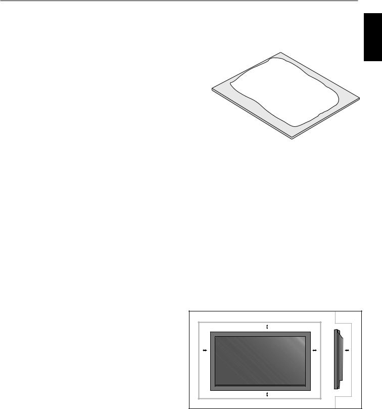
An optional stand or mounting apparatus can be installed .
Optional table top stand
When stand or mounting apparatus is to be installed
while the unit is face-down (Figure 1), be sure to lay the
Figure 1
protective sheet (the foam sheet that the unit was wrapped in) underneath the unit on order to prevent damage to the screen.
This unit must be used with a stand or some type of mounting apparatus. This unit is not designed for use without additional support.
• |
For correct Installation and Mounting it is |
Table |
|
recommended to use a trained, authorized dealer. |
|
• |
Failure to follow correct mounting procedures could |
Protective Sheet |
|
result in dame to the unit or to the installer. |
|
•Product warranty does not cover damage caused by improper installation.
CAUTION:
•To install, follow those instructions included with the stand or mounting apparatus. Use only those devices recommended by the manufacturer.
•Make sure to install stand or mounting apparatus to the unit while on a surface that is strong and stable enough to support the weight of the unit, such as a floor or sturdy table.
•Use the specified clasps for installation.
•Take necessary steps to prevent the unit from tipping or falling.
Mounting Location
The ceiling and wall must be strong enough to support the monitor and mounting accessories.
•DO NOT install in locations where a door or gate can hit the unit.
•DO NOT install in areas where the unit will be subjected to strong vibrations and dust.
•DO NOT install near where the main power supply enters the building.
•DO NOT install in where people can easily grab and hang onto the unit or the mounting apparatus.
•When mounting in an enclosure or in a recessed area, as in a wall, leave at least 2 inches (50mm) of space between the monitor and the wall for proper ventilation (Figure 2).
•Allow adequate ventilation or provide air conditioning around the monitor, so that heat can properly dissipate away from the unit and mounting apparatus.
Figure 2
|
50mm (2") |
|
50mm (2") |
50mm (2") |
50mm (2") |
|
50mm (2") |
|
English
English-6
Installation - continued
Mounting on Ceiling
•Ensure that the ceiling is sturdy enough to support the weight of the unit and the mounting apparatus over time, against earthquakes, unexpected vibrations, and other external forces.
•Be sure the unit is mounted to a solid structure within the ceiling, such as a support beam. Secure the monitor using bolts, spring lock washers, washer and nut.
•DO NOT mount to areas that have no supporting internal structure. DO NOT use wood screws or anchor screws for mounting. DO NOT mount the unit to trim or to hanging fi xtures.
Maintenance
•Periodically check for loose screws, gaps, distortions, or other problems that may occur with the mounting apparatus. If a problem is detected, please refer to qualified personnel for service.
•Regularly check the mounting location for signs of damage or weakness that may occur over time.
Please note the following when mounting on wall or ceiling.
•When using mounting accessories other than those that are NEC approved, they must comply with the VESAcompatible (FDMlv1) mounting method.
•NEC strongly recommends using size M8 screws (16mm + thickness of bracket in length). If using screws longer than 16mm, check the depth of the hole.(Recommended Fasten Force: 1125 - 1375N•cm) NEC recommends mounting interfaces that comply with UL1678 standard in North America.
Unit |
Mounting |
|
Bracket |
Screw
16mm
Thickness
of Bracket
Screw length should equal depth of hole (16mm) + the thickness of mounting bracket.
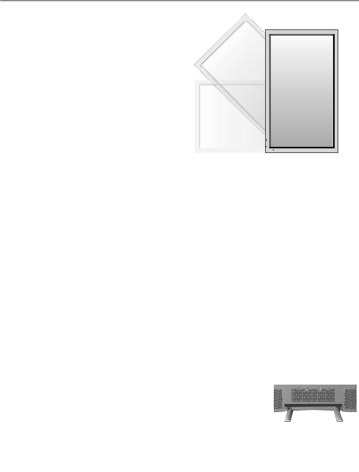
Orientation
When using the display in the portrait position, the monitor should be rotated clockwise so that the left side is moved to the top and the LED indicator light is on the bottom. This will allow for proper ventilation and will extend the lifetime of the monitor. Improper ventilation may shorten the lifetime of the monitor.
When using the display in the portrait position, please turn the Cooling Fan "ON" in the OPTION2 OSD menu.
Cable Management
To conveniently manage cables, use the cable clamps provided to bundle the power cord together with the signal and audio cables at the back of the display.
To attach cable clamps:
1.Attach the cable clamps to the display. Insert the anchor of the clamp into the hole on the back of the display. There are 4 cable clamps and 4 clamp holes on the unit.
2.After the cable clamp is positioned on the display, wrap the end around the cables. Place the end of the clamp into the slot near the anchor. Pull until cables are snug.
Clamps are designed to stay in place. Once in position, they will be difficult to remove.
3. Cables can be routed to the right or left of the clamp. Use the beaded bands to secure the cables together along their length. Make sure the cables are fully supported.
To detach clamps:
Using pliers, twist the clamp 90 degrees and pull outward. It is possible that the clamp can weaken over time and removing it may cause damage to the clamp.
Anchor Slot
Holes for Clamp anchors
Closed Clamp
English-7
|
Installation - continued |
Using the Remote: |
Operating Range for the Remote Control |
|
Point the top of the remote control toward the monitor’s |
Install the remote control batteries. |
remote sensor while pressing buttons. The remote control |
The remote control is powered by AA batteries. To install or |
can be used from the front of the monitor at a maximum |
replace batteries: |
distance of 7 m/23 ft. from the front of the Plasma monitor’s |
|
remote control sensor. The maximum horizontal and vertical |
|
angle for use of the remote is 30 degree within a distance of |
|
3.5 m/11.5 ft. |
|
CAUTION |
A.Press and slide to open the cover.
B.Align the batteries according to the (+) and (–) indications inside the case.
C.Replace the cover.
CAUTION: Incorrect usage of batteries can result in leaks or bursting. NEC recommends the following battery use:
•Place “AA” size batteries matching the (+) and (-) signs on each battery to the (+) and (-) signs of the battery compartment.
The remote control may not function when direct sunlight or strong illumination strikes the remote control sensor of the Plasma monitor, or when there is an object in the path of the sensor.
Handling the Remote Control
Do not open the remote control other than to install batteries. Do not allow water or other liquid to splash onto the remote control. If the remote control gets wet, wipe it dry immediately.
Avoid exposure to heat and steam.
•Do not mix battery brands.
•Do not combine new and old batteries, or mix brands. This can shorten battery life or cause liquid leakage of batteries.
•Remove dead batteries immediately to prevent battery acid from leaking into the battery compartment.
•Do not touch exposed battery acid, it may injure skin.
•Do not drop or mishandle the remote.
•Do not get the remote control wet. If the remote does get wet, wipe dry immediately.
•Avoid excessive heat and humidity.
•Do not dispose of batteries in fire.
•Please follow government regulations or public environmental rules that apply in your country/area when disposing of used batteries.
•When replacing, use only conventional nonrechargeable alkaline or manganese batteries.
•There is a risk of explosion if batteries are replaced incorrectly.
NOTE: If you do not intend to use the Remote Control for a long period of time, remove the batteries.
30 30
30
 +
+
+  +
+
English
English-8
Part Names and Functions
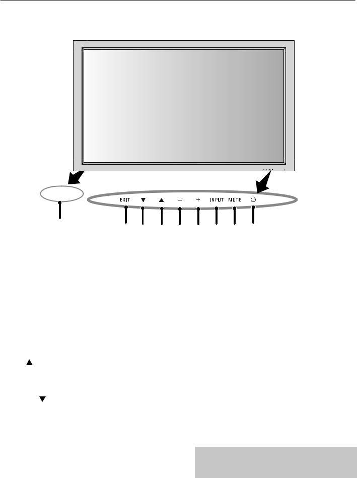
Control Panel
 9
9
EXIT |
INPUT |
MUTE |
ON 
 OFF
OFF
|
10 |
8 |
7 |
6 |
|
|
|||
1) |
POWER |
|
|
|
|
Switches the power on/standby. |
|
|
|
2) |
MUTE |
|
|
|
|
Switches the audio mute ON/OFF. |
|
|
|
3) |
INPUT |
|
|
|
|
Switches between input sources. |
|
|
|
|
Acts as SET button within the OSD menu. |
|
|
|
4) |
PLUS (+) |
|
|
|
|
Increases the setting adjustment within OSD menu. |
|
||
5) |
MINUS (-) |
|
|
|
|
Decreases the setting adjustment within OSD menu. |
|
||
6) |
UP ( ) |
|
|
|
|
Increases the volume level when the OSD is off. |
|
||
|
Moves area up to select which setting to is to be adjusted |
|||
|
within OSD menu. |
|
|
|
7) |
DOWN ( ) |
|
|
|
|
Decreases the volume level when the OSD is off. |
|
||
|
Moves down to select which setting is to be adjusted within |
|||
|
OSD menu. |
|
|
|
5 |
4 |
3 |
2 |
1 |
8) |
EXIT |
|
|
|
Activates the OSD menu when the OSD menu is off. Exits from the current menu being displayed to the previous menu within the OSD.
9) Remote control sensor and Power indicator
Receives the signal when using the wireless remote control. Glows green when the monitor is active. Glows red when the monitor is in Standby mode. Glows Amber when the monitor is in POWER SAVE mode.
A red blinking Power indicator means that the monitor has detected a failure. Contact qualified personnel in case of failure.
10) Main Power Switch
Seesaw switch to turn the main power on/off.
Mode |
Status indicator light |
|
|
Power On |
Green |
Standby |
Red |
Power save |
Amber |
Diagnosis |
Red blinking |
(Detecting failure) |
|
|
|
NOTE:
The POWER button does not completely turn off the display. Use the Main Power Switch to completely turn off the display.
English-9
Part Names and Functions
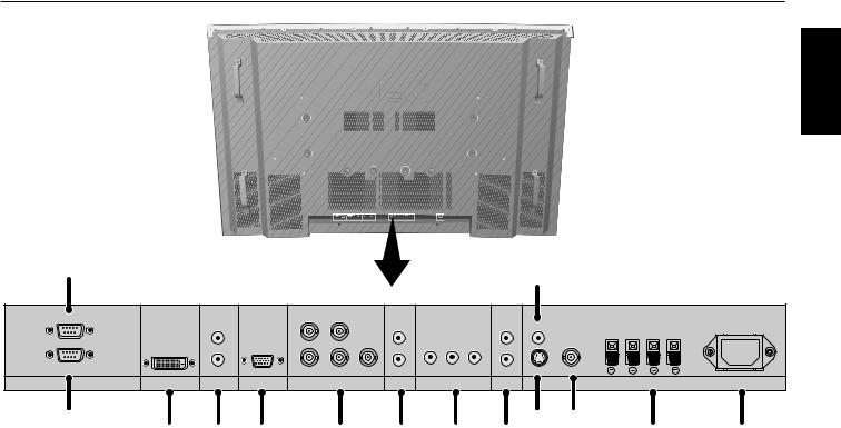
Terminal Panel
English
1 |
|
|
|
|
|
|
|
|
|
12 |
|
|
|
|
|
|
|
|
|
|
|
|
|
|
|
|
|
OUT |
|
|
|
HD |
VD |
|
|
|
|
|
|
|
|
|
|
R |
|
|
|
R |
|
|
R |
IN |
R |
L |
|
|
|
|
|
|
|
|
|
|
|
|
|
||
IN |
|
L(MONO) |
|
R/Cr/Pr |
G/Y B/Cb/pb |
L(MONO) |
Y |
Cr/Pr Cb/Pb |
L(MONO) |
S-VIDEO IN IN/OUT |
|
|
|
EXTERNAL CONTROL |
DVI |
AUDIO3 |
VGA |
RGBHV / DVD/HD2 |
AUDIO2 |
|
DVD/HD1 |
AUDIO1 |
VIDEO |
|
SPEAKER (S) |
AC IN |
|
2
3 |
4 |
5 |
6 |
1)EXTERNAL CONTROL OUT (D-Sub 9 pin)
Connect RS-232C output to a second monitor.
2)EXTERNAL CONTROL (D-Sub 9 pin)
Connect RS-232C input to external equipment such as a PC in order to control RS-232C functions.
3) DVI
Input digital RGB signals from a computer or HDTV device having a digital RGB output.
4) AUDIO3
Input the audio signal from external equipment such as a computer, VCR or DVD player.
5)VGA (Mini D-Sub 15 pin)
Analog computer input or output.
For proper operation select "D-SUB INPUT" in the OPTION1 OSD menu.
6)RGBHV/DVD/HD2
RGBHV: Input RGB signals from RGB equipment. A Sync-on-Green signal can be connected using the G connector.
DVD/HD2: Connect equipment such as a DVD player, HDTV device, or set-top box.
This input can be used with an RGB or component source. For proper operation select "BNC INPUT" in the OPTION1 OSD menu.
7) AUDIO2
Input the audio signal from external equipment such as a computer, VCR or DVD player.
|
|
10 |
11 |
|
7 |
8 |
9 |
13 |
14 |
8) |
DVD/HD1 |
|
|
|
|
Connect equipment such as a DVD player, HDTV device, |
|||
|
or set-top box. |
|
|
|
9) |
AUDIO1 |
|
|
|
|
Input the audio signal from external equipment such as a |
|||
|
computer, VCR or DVD player. |
|
||
10) |
S-VIDEO in |
|
|
|
|
Input S-video. |
|
|
|
11) |
VIDEO1 |
|
|
|
|
Composite video input or output. |
|
||
12) |
VIDEO2 |
|
|
|
|
Composite video input. |
|
||
13)EXTERNAL SPEAKER (L and R) connector
Connects to optional speakers. Output the audio signal from AUDIO 1, 2, and 3 to external speakers.
NOTE: Speaker Terminal is for 8W + 8W (8 ohm).
14)AC IN
Connects with the supplied power cord.
Information:
For Y/Cb/Cr connections, use the DVD/HD1 or DVD/HD2 terminals.
For SCART connections there are 3 ways to connect: SCART1: Connect R/G/B to the DVD/HD2 terminals and composite sync. to the HD terminal.
SCART2: Connect R/G/B to the DVD/HD2 terminals and composite sync. to the VIDEO1 terminal.
SCART3: Connect R/G/B + composite sync. to the VGA terminal.
English-10
Part Names and Functions - continued
POWER ON STANDBY
1
2 |
|
|
|
|
|
|
|
|
|
|
|
|
|
|
PICTURE |
|
|
||||
3 |
|
|
|
|
|
|
|
RGB |
DVD/HD VIDEO |
MEMORY |
|
|
|||||||||
|
|
|
|
|
|
|
|
|
|
|
|
|
|
|
|
|
|
|
|
|
|
4 |
|
|
|
|
|
|
|
|
|
|
|
|
|
|
|
||||||
|
|
PICTURE |
|
|
|
|
|
|
|
|
|
|
|
|
|||||||
5 |
|
|
|
|
|
MODE |
|
SIZE |
|
|
|
|
|
|
|||||||
|
|
|
|
|
|
|
|
|
|
|
|
|
|
|
|
|
|
|
|
||
6 |
|
|
|
|
|
|
|
|
|
|
|
|
|
|
|
|
|
||||
1 |
2 |
|
|
3 |
|
|
|
|
|||||||||||||
|
|
|
|
|
|
|
|
|
|
|
|||||||||||
7 |
|
|
|
4 |
5 |
|
|
6 |
|
|
|
|
|||||||||
|
|
|
|
|
|
|
|
|
|
|
|
|
|
|
|
|
|
|
|
||
|
|
7 |
8 |
|
|
9 |
|
|
|
|
|||||||||||
|
|
|
|
|
|
|
|
|
|
|
|||||||||||
|
|
|
|
|
|
|
|
|
|
0 |
|
|
|
|
|
|
|
|
|||
8 |
|
|
|
|
DISPLAY |
|
|
|
|
|
|
|
MENU |
|
|
||||||
|
|
|
|
|
|
|
|
|
|
|
|
|
|
|
|
|
|
15 |
|||
|
|
|
|
|
|
|
|
|
|
|
|
|
|
|
|
|
|||||
|
|
|
|
|
|
|
|
|
|
|
|
|
|
|
|
|
|||||
9 |
|
|
|
|
|
|
|
|
|
|
|
|
|
|
|
|
|
|
|
|
16 |
|
|
|
|
|
|
|
|
|
|
|
SET |
+ |
|
|
|
|
|||||
|
|
|
|
|
|
|
|
|
|
|
|
|
|
17 |
|||||||
|
|
|
|
|
|
|
AUTO |
|
|
|
|
|
|
|
|
|
|
||||
|
|
|
|
|
|
|
|
|
|
|
|
|
|
EXIT |
|
|
|||||
|
|
|
|
|
|
SET UP |
|
|
|
|
|
|
|
|
|
||||||
10 |
|
|
|
|
|
|
|
|
|
|
|
|
|
|
|
|
|
|
18 |
||
|
|
|
|
|
|
|
|
|
|
|
|
|
|
|
|
|
|||||
11 |
|
|
|
|
VOL |
|
|
|
|
|
|
ZOOM |
19 |
||||||||
|
|
|
|
|
+ |
|
|
POINTER |
+ |
|
|
||||||||||
|
|
|
|
|
|
|
|
|
|||||||||||||
12 |
|
|
|
|
|
|
|
|
|
|
|
|
|
|
|||||||
|
|
|
|
|
|
|
|
|
|
|
|
|
|
||||||||
|
|
|
|
|
|
MUTE |
|
|
20 |
||||||||||||
|
|
|
|
|
|
|
|
|
|
|
|
|
|
|
|||||||
|
|
|
|
|
|
|
|
|
|
|
|
|
|
|
|||||||
|
|
|
|
|
|
|
|
|
|
|
|
|
|
|
|
|
|
|
|||
|
|
|
|
|
|
|
|
SPLIT SCREEN |
|
|
|
|
|||||||||
|
|
|
|
|
|
|
|
|
|
|
|
|
|
||||||||
13 |
|
|
|
|
|
|
PIP |
|
|
S BY S |
SINGLE |
|
|
||||||||
|
|
|
|
|
|
|
|
|
|
|
|
|
|
|
|
|
|
|
|
||
|
|
|
|
|
|
|
|
SWAP |
|
SELECT/FREEZE |
CAPTURE |
|
|
||||||||
|
|
|
|
|
|
|
|
|
|
|
|
|
|
|
|
|
|
|
|
|
|
|
|
|
|
|
|
|
|
REMOTE ID |
|
|
|
|
|
|
|||||||
14 |
|
|
|
|
|
SET |
RESET |
SLEEP |
21 |
||||||||||||
|
|
|
|
|
|
|
|
|
|
|
|
|
|
|
|
|
|||||
|
|
|
|
|
|
|
|
|
|
|
|
|
|
|
|
|
|||||
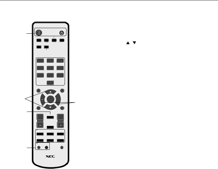
REMOTE CONTROLLER RU-M113
1)POWER ON/STANDBY
Switches the power on/standby.
*If the Power Indicator on the display is not glowing, then no controls will work.
2)VIDEO
Switches the input signal to the VIDEO source.
3) RGB
Switches the input signal to the RGB source.
4) DVD/HD
Switches the input signal to the DVD/HD source.
5) PICTURE MODE
Selects Picture Mode: [STANDARD], [BRIGHT], [CINEMA1], [CINEMA2], [DEFAULT].
STANDARD: for viewing in a bright room BRIGHT: brighter picture than STANDARD CINEMA1, 2: for viewing in a dark room, good for movies
DEFAULT: factory default settings
6) SIZE
Set the aspect ratio of the image.
Remote Control Functions
7) KEYPAD
Set REMOTE ID.
8) DISPLAY
Turn on/off the Information OSD.
9)
Move selection up or down
10) AUTO SETUP
Adjusts the CLOCK PHASE, CLOCK, and POSITION settings automatically. (Analog RGB signal input only)
11) POINTER
Turn on/off the pointer.
12) VOLUME
Increases/Decreases sound level.
13) SPLIT SCREEN
PIP: Picture-in-Picture mode. S BY S: Side-by-side mode.
SINGLE: Returns to normal mode. SWAP: Swaps the Split Screen images.
When the QUICK SWAP function (see OSD OPTION4) is ON, SWAP can be used to change signal input. (Single screen mode)
SELECT/FREEZE: Selects which input is active when in split screen mode.
When the PIC FREEZE function (see OSD Option4) is operating, SELECT/FREEZE can be used to display still pictures on the sub screen.
CAPTURE : Captures still picture.
14) REMOTE ID
Activates REMOTE ID function.
15) MENU
Turns ON/OFF menu mode.
16) SET
Makes selection.
17) - , +
Increases or decreases amount of adjustment.
18) EXIT
Goes to the previous menu.
19) ZOOM
Enlarges or reduces the picture.
20) MUTE
Mutes audio output.
21)SLEEP
Sleep timer.
NOTE: Any buttons without a corresponding explanation will not work with the Plasmasync display.
English-11
 Loading...