

Page 1
DATA SHEET
DATA SHEET
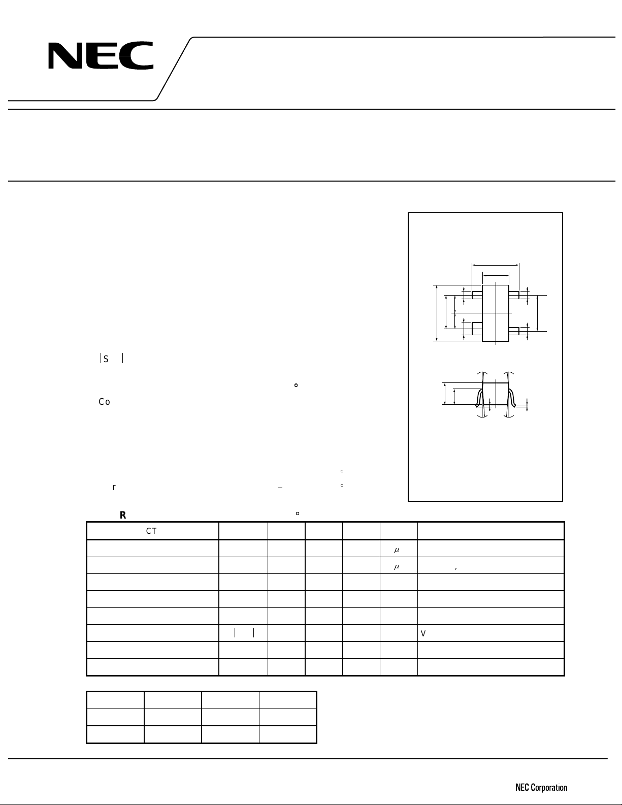
MICROWAVE LOW NOISE AMPLIFIER
NPN SILICON EPITAXIAL TRANSISTOR
4 PINS MINI MOLD
DESCRIPTION
The 2SC4094 is an NPN epitaxial silicon transistor designed for use in
low-noise and small signal amplifiers from VHF band to UHF band. Lownoise figure, high gain, and high current capability achieve a very wide
dynamic range and excellent linearity. This achieved by direct nitride
passivated base surface process (DNP process) which is an NEC
proprietary new fabrication technique.
FEATURES
• NF = 1.2 dB TYP. @f = 1.0 GHz, VCE = 8 V, IC = 7 mA
•S
2
21e
= 15 dB TYP. @f = 1.0 GHz, VCE = 8 V, IC = 20 mA
SILICON TRANSISTOR
2SC4094
PACKAGE DIMENSIONS
(Units: mm)
+0.2
2.8
−0.3
+0.2
+0.1
−0.05
0.4
3
(1.9)
4
+0.1
−0.05
0.4
(1.8)
2.9±0.2
0.950.85
+0.1
+0.1
−0.05
0.4
−0.05
0.6
1.5
−0.1
2
1
5° 5°
ABSOLUTE MAXIMUM RATINGS (TA = 25
Collector to Base Voltage V
Collector to Emitter Voltage V
Emitter to Base Voltage V
Collector Current I
Total Power Dissipation P
Junction Temperature T
Storage Temperature T
CBO
CEO
EBO
C
T
j
stg
ELECTRICAL CHARACTERISTICS (TA = 25
C)
20 V
10 V
1.5 V
65 mA
200 mW
150
65 to +150C
C)
+0.2
−0.1
0.8
1.1
5° 5°
0 to 0.1
PIN CONNECTIONS
1.
Collector
2.
C
3.
4.
Emitter
Base
Emitter
CHARACTERISTIC SYMBOL MIN. TYP. MAX. UNIT TEST CONDITIONS
Collector Cutoff Current I
Emitter Cutoff Current I
DC Current Gain h
Gain Bandwidth Product f
Feed-Back Capacitance C
Insertion Power Gain
S
CBO
EBO
21e
1.0
1.0
FE
T
re
50 250 VCE = 8V, IC = 20 mA
9 GHz VCE = 8 V, IC = 20 mA, f = 1.0 GHz
0.25 0.8 pF VCB = 10 V, IE = 0, f = 1.0 MHz
2
13 15 dB VCE = 8 V, IC = 20 mA, f = 1.0 GHz
AVCB = 10 V, IE = 0
AVEB = 1 V, IC = 0
Maximum Available Gain MAG 17 dB VCE = 8 V, IC = 20 mA, f = 1.0 GHz
Noise Figure NF 1.2 2.0 dB VCE = 8 V, IC = 7 mA, f = 1.0 GHz
+0.1
−0.06
0.16
hFE Classification
Class R36/RCF * R37/RCG * R38/RCH *
Marking R36 R37 R38
FE
h
Document No. P10366EJ1V1DS00 (1st edition)
Date Published March 1997 N
Printed in Japan
50 to 100 80 to 160 125 to 250 * Old Specification / New Specification
1987©
Page 2
2SC4094
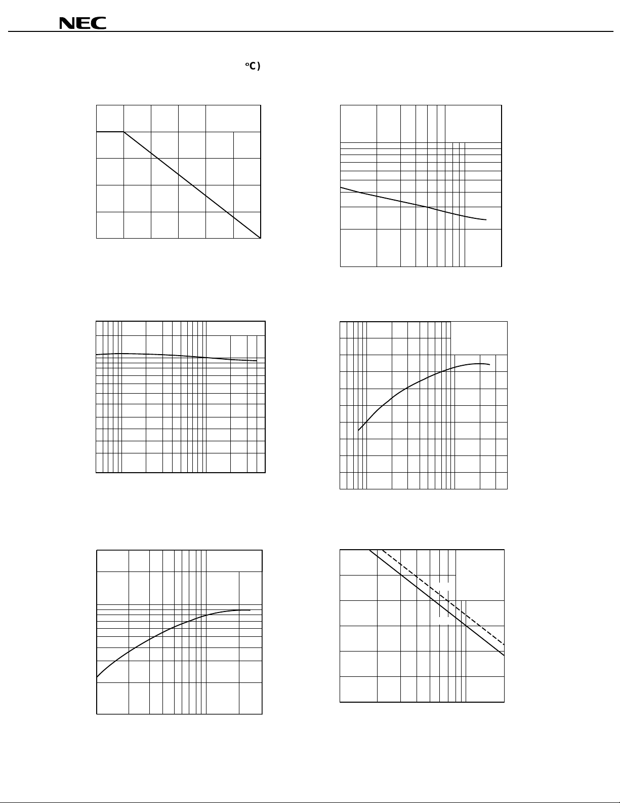
TYPICAL CHARACTERISTICS (TA = 25
TOTAL POWE R DISSIPATION vs.
AMBIENT TEMPERATURE
Free air
200
100
-Total Power Dissipation-mW
T
P
200
100
0
50
A
-Ambient Temperature-°C
T
DC CURRENT GAIN vs.
COLLECTOR CURRENT
100
VCE = 8 V
C)
150
FEED-BACK CAPACITANCE vs.
2.0
COLLECTOR TO BASE VOLTAGE
f = 1.0 GHz
1.0
0.7
0.5
0.3
-Feed-back Capacitance-pF
0.2
re
C
0.1
123571020
VCB-Collector to Base Voltage-V
INSERTION GAIN vs.
20
COLLECTOR CURRENT
VCE = 8 V
f = 1.0 GHz
50
-DC Current Gain
FE
h
20
10
0.5 1 5 10 50
IC-Collector Current-mA
GAIN BANDWIDTH PRODUT vs.
30
COLLECTOR CURRENT
VCE = 8 V
20
10
7
5
3
-Gain Bandwidth Product-GHz
2
T
f
32571020301
I
C
-Collector Current-mA
10
-Insertion Gain-dB
2
|
21e
|S
0
12 5102040
IC-Collector Current-mA
MAXIMUM AVAILABLE GAIN,INSERTION
GAIN vs. FREQUENCY
30
MAG
20
2
|S
21e
|
10
-Insertion Gain -dB
2
|
21e
|S
MAG-Maximum Available Gain-dB
0
0.1 0.2 0.5 1.0 2.0
f-Frequency-GHz
VCE = 8 V
C
= 20 mA
I
2
Page 3
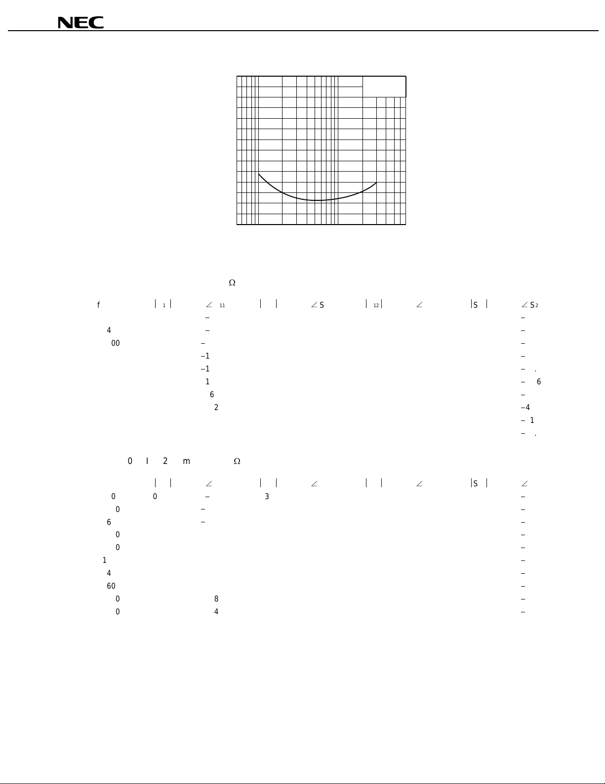
S-PARAMETER
VCE = 8.0 V, IC = 5.0 mA, ZO = 50
f (MHz)
200
400
600
800
1000
1200
1400
1600
1800
2000
11
S
0.774
0.631
0.523
0.460
0.426
0.416
0.417
0.430
0.443
0.458
7
6
5
4
3
NF-Noise Figure-dB
2
1
0
0.5 1 5 10 50 70
11
S
47.8
88.8
120.9
145.1
166.6
178.2
163.0
152.1
142.1
136.5
NOISE FIGURE vs.
COLLECTOR CURRENT
C
-Collector Current-mA
I
21
S
12.689
9.952
7.813
5.966
4.841
4.065
3.413
3.035
2.659
2.482
S
146.5
119.4
100.9
87.6
76.7
68.8
60.7
54.1
48.0
44.3
2SC4094
VCE = 8 V
f = 1.0 GHz
21
12
S
0.031
0.048
0.058
0.067
0.074
0.083
0.087
0.098
0.105
0.114
S
65.4
53.4
46.2
43.9
43.8
43.5
41.2
42.8
40.1
43.0
12
22
S
0.882
0.723
0.611
0.564
0.515
0.488
0.459
0.443
0.428
0.414
S
19.1
29.5
33.4
34.5
37.6
39.6
44.1
45.9
51.1
53.5
22
VCE = 8.0 V, IC = 20.0 mA, ZO = 50
f (MHz)
200
400
600
800
1000
1200
1400
1600
1800
2000
11
S
0.461
0.364
0.338
0.330
0.334
0.344
0.359
0.383
0.401
0.419
89.8
135.8
163.4
177.9
163.2
153.9
143.1
136.1
128.3
124.7
11
S
21
S
23.331
13.501
9.535
7.083
5.604
4.722
3.982
3.517
3.094
2.882
S
121.6
99.2
86.4
77.5
69.3
63.5
56.8
51.1
45.6
42.7
21
12
S
0.021
0.033
0.046
0.056
0.070
0.084
0.091
0.104
0.116
0.127
S
60.7
61.2
61.5
62.1
60.0
60.4
54.9
54.5
49.9
50.8
12
22
S
0.665
0.511
0.448
0.430
0.402
0.385
0.362
0.350
0.337
0.323
S
27.7
30.5
29.5
29.5
32.5
34.8
39.5
42.1
47.4
50.5
22
3
Page 4
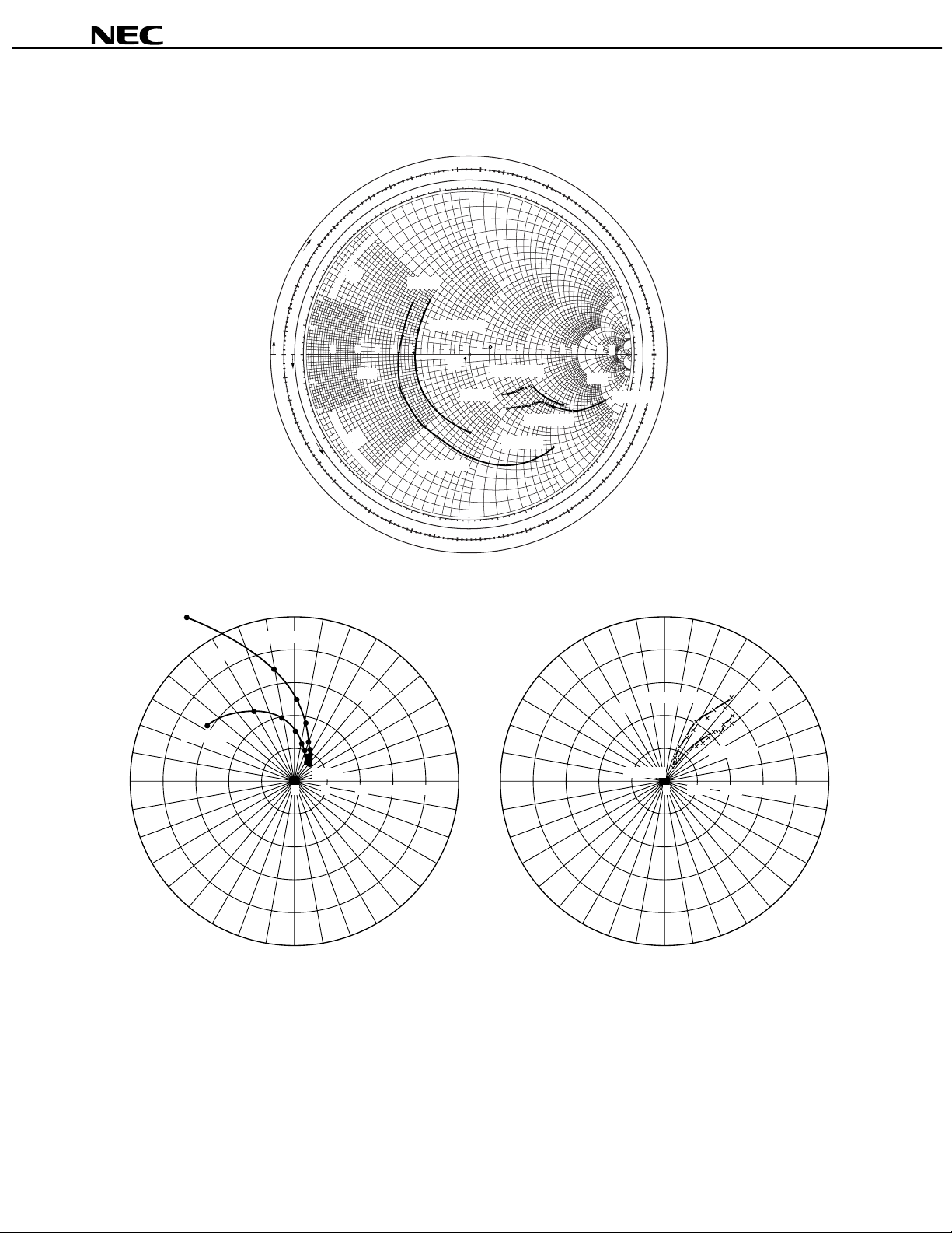
S-PARAMETER
21e
-FREQUENCY
S
CONDITION V
120°
S
11e
, S
22e
CE
= 8 V
I
C
= 20/5 mA
-FREQUENCY
D
R
A
W
O
T
S
H
T
0.02
G
N
E
L
E
V
A
0.01
W
0
0.49
0.48
CONDITION VCE = 8 V, IC = 20/5 mA, freq. = 0.2 to 2 GHz (Step 200 MHz)
0.07
0.43
130
0.06
0.44
0.05
140
0.4
0.45
R
O
T
A
R
0.04
E
0.46
N
E
G
0.03
0.47
E
R
G
E
D
N
0.48
I
T
N
E
I
C
F
0.49
F
E
O
C
N
0
O
I
T
C
E
L
F
D
E
A
R
O
0.01
L
0.1
F
O
D
R
E
A
L
G
W
N
O
0.02
A
T
S
H
T
G
N
E
0.03
0.47
0.46
CO
E
C
N
A
T
C
0.3
150
A
E
+JX
R
––––
(
E
V
Z
I
T
I
S
E
OS
P
0.2
0.1
0
0.1
S
T
0.2
N
160
E
−
N
O
P
L
E
)
OM
V
A
C
E
W
0.3
C
150
N
−
0.04
A
T
C
0.4
0.05
140
−
0.45
0.06
0.44
0.43
freq. = 0.2 to 2 GHz (Step 200 MHz)
90°
IC = 20 mA
0.2 GHz
2SC4094
0.13
0.12
0.38
0.9
R
)
O
2 GHz
0.12
0.38
0.37
90
1.0
0.2
0.4
0.4
0.2
1.0
1.2
0.2
0.4
0.6
0.2
1.0
−
90
0.14
0.36
0.35
80
1.2
1.4
0.6
0.8
1.0
1.0
0.8
0.6
1.4
1.6
1.8
IC = 20 mA
0.8
1.0
1.0
0.8
0.2 GHz
0.6
0.4
1.4
1.2
−
80
0.14
0.13
0.36
0.37
0.15
0.16
0.34
70
0060
1.6
1.8
2.0
3.0
IC = 5 mA
1.8
1.6
−
70
0.16
0.15
0.35
0.17
0.33
0.18
0.32
0.19
50
0.31
2.0
40
3.0
4.0
10
4.0
5.0
S
22e
3.0
−40
0.19
−50
2.0
0.18
0.32
−
60
0.17
0.33
0.34
12e
-FREQUENCY
S
CONDITION V
120°
0.20
0.30
0.21
0.29
30
0.22
0.28
20
6.0
0.23
0.27
10
10
0.24
0.26
20
50
0.25
0.25
20
0
50
0.24
20
0.26
−10
10
0.23
0.27
0.2 GHz
−20
0.22
5.0
0.28
4.0
−30
0.21
0.29
0.20
0.30
0.31
CE
= 8 V
I
C
= 20/5 mA
freq. = 0.2 to 2 GHz (Step 200 MHz)
90°
60°
0.11
0.10
0.39
0.40
0.09
0.41
0.08
0.42
120
0.5
T
N
E
N
O
P
M
)
O
0.6
110
0.7
2 GHz
100
0.9
0.8
IC = 20 mA
0.2
0.3
0.4
0.5
0.6
0.7
0.8
REACTANCE COMPONENT
––––
(
0.7
0.09
IC = 5 mA
0.8
110
−
0.10
0.11
0.40
0.39
Z
0.9
100
−
11e
O
(
−JX
––––
Z
A
E
R
IVE
T
A
G
NE
0.5
130
−
0.6
0.07
120
−
0.08
0.42
0.41
60°
180°
150°
−150°
IC = 5 mA
−120°
S
21e
2GHz
40 8 12 16 20
−90°
−60°
30°
−30°
150°
S
12e
IC = 20 mA
2GHz
30°
IC = 5 mA
180°
0°
0.2 GHz
0.040 0.08 0.12 0.16 0.2
−150°
−120°
−60°
0°
−30°
−90°
4
Page 5

[MEMO]
2SC4094
5
Page 6

[MEMO]
2SC4094
6
Page 7

[MEMO]
2SC4094
7
Page 8

2SC4094
No part of this document may be copied or reproduced in any form or by any means without the prior written
consent of NEC Corporation. NEC Corporation assumes no responsibility for any errors which may appear in this
document.
NEC Corporation does not assume any liability for infringement of patents, copyrights or other intellectual
property rights of third parties by or arising from use of a device described herein or any other liability arising
from use of such device. No license, either express, implied or otherwise, is granted under any patents,
copyrights or other intellectual property rights of NEC Corporation or others.
While NEC Corporation has been making continuous effort to enhance the reliability of its semiconductor devices,
the possibility of defects cannot be eliminated entirely. To minimize risks of damage or injury to persons or
property arising from a defect in an NEC semiconductor device, customers must incorporate sufficient safety
measures in its design, such as redundancy, fire-containment, and anti-failure features.
NEC devices are classified into the following three quality grades:
"Standard", "Special", and "Specific". The Specific quality grade applies only to devices developed based on
a customer designated "quality assurance program" for a specific application. The recommended applications
of a device depend on its quality grade, as indicated below. Customers must check the quality grade of each
device before using it in a particular application.
Standard: Computers, office equipment, communications equipment, test and measurement equipment,
audio and visual equipment, home electronic appliances, machine tools, personal electronic
equipment and industrial robots
Special: Transportation equipment (automobiles, trains, ships, etc.), traffic control systems, anti-disaster
systems, anti-crime systems, safety equipment and medical equipment (not specifically designed
for life support)
Specific: Aircrafts, aerospace equipment, submersible repeaters, nuclear reactor control systems, life
support systems or medical equipment for life support, etc.
The quality grade of NEC devices is "Standard" unless otherwise specified in NEC's Data Sheets or Data Books.
If customers intend to use NEC devices for applications other than those specified for Standard quality grade,
they should contact an NEC sales representative in advance.
Anti-radioactive design is not implemented in this product.
M4 96. 5
 Loading...