

Page 1

USER MANUAL
MH-B373
P le as e Re ad O ve r T hi s Ma nu al B ef o re O pe ra ti ng T h e Li gh t Fi xt ur e
Page 2

ABLE OF CONTENTS
T
PART 1 P RODU CT SPE CIFICATIO NS..... .... .... .... ....... .... .... .... ....... .1.
1.1 --PRO DUCT SP ECIFI CATIONS ..... ..... ..... ..... ..... ..... ..... ..... ..... ..... ..... 1.
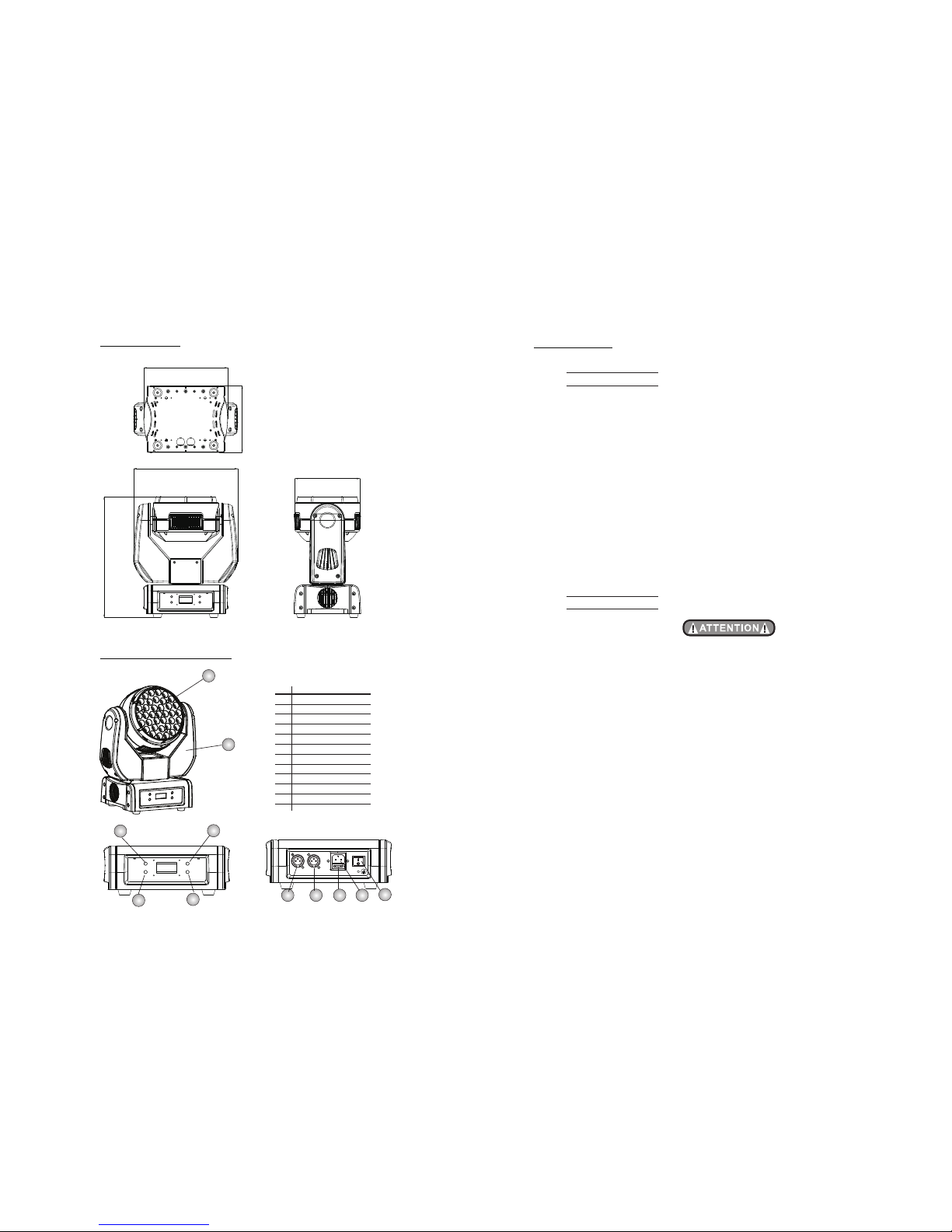
1.2 --DIM ENSIO NS... ..... ..... ..... ..... ..... ..... ..... ..... ..... ..... ..... ..... ..... ..... ..... 2.
1.3 --PRO DUCT FE ATURES ..... ..... ..... ..... ..... ..... ..... ..... ..... ..... ..... ..... ....2 .
PART 2 I NSTAL LATIO N... ....... .... ....... .... .... ....... .... ....... .... .... ....... ..4.
2.1- -MOUN TING.. ..... ..... ..... ...... ..... ..... ..... ...... ..... ..... ..... ...... ..... ..... ..... ...4.
2.3 --FUS E REPLAC EMENT.. ..... ...... ..... ..... ..... ...... ..... ..... ..... ..... ...... ..... .5.
2.2 --SET TING UP... ..... ..... ..... ...... ..... ..... ..... ...... ..... ..... ..... ...... ..... ..... ..... 5.
PART 4 USING DM X512 C ONTR OLLE R............ .... .... .... .... ............1 3.
PART 3 DISPLAY PANEL OPER ATION. .... .... .... .... ......... .... .... .... .... ..6.
3.1 --BAS IC... ..... ..... ..... ..... ..... ..... ..... ..... ..... ..... ..... ..... ..... ..... .... ..... ..... ...6.
3.3 --INT RO... ..... ..... ..... ..... ..... ..... ..... ..... ..... ..... ..... ..... ..... ..... .... ..... ..... ...8.
3.2 --MEN U.... ..... ..... ..... ..... ..... ..... ..... ..... ..... ..... ..... ..... ..... ..... ..... ..... .... ..7.
3.4 --INV ERT.... ..... ..... ..... ..... ..... ..... ..... ..... ..... ..... ..... ..... ..... ..... ..... ..... ..... 8.
3.7 --EDI T... ..... ..... ..... ..... ..... ..... ..... ..... ..... ..... ..... ..... ..... ..... .... ..... ..... ..... .9.
1.4 SAF ETY WARN ING-- ... ..... ..... ..... ..... ..... ..... ..... ..... ..... ..... ..... ..... ..... ..3.
3.8 --EXT RA... ..... ..... ..... ..... ..... ..... ..... ..... ..... ..... ..... ..... ..... ..... .... ..... ..... .11.
PART 5 AP PENDIX....... .... .... .... .... .... ......... .... .... .... .... .... ............. ...1 7 .
5.1 --MAI NTENA NCE.. ..... ..... ..... ..... ..... ..... ..... ..... ..... ..... ..... ..... ..... ..... 17.
4.1 --CHA NNEL ASS IGNME NT..... ..... ..... ..... ..... ..... ..... ..... ..... ..... ..... .... 13 .
3.5 --RAN GE... ..... ..... ..... ..... ..... ..... ..... ..... ..... ..... ..... ..... ..... .... ..... ..... ..... ..9.
3.6 --SPE CIAL. ..... ..... ..... ..... ..... ..... ..... ..... ..... ..... ..... ..... ..... ..... .... ..... ..... . 9.
3.9 --CAL IB... ..... ..... ..... ..... ..... ..... ..... ..... ..... ..... ..... ..... ..... ..... .... ..... ..... .. 11.
3.1 0--DE FAULT.... ..... ..... ..... ..... ..... ..... ..... ..... ..... ..... ..... ..... ..... ..... ..... ... 12.
1
Electr ical
Voltage :AC1 00~2 40V,50 /60Hz
Rated Po wer: 160W
LED
LED:37 PC(1 3R+1 2G+1 2B)
Coolin g:Fo rced a ir con vection
Functi on
Operat ion
Contro l mode :Mas ter- Slav e/A uto/ Cust om/ So und
LCD disp lay
DMX512 C hs:9 CHS/ 1 2CHS
Pan/Til t
Pan 540 Tilt 270
Pan/Til t spee d
User-s elec tabl e Pan/ Tilt r ange s
Size:4 00x3 80x2 80mm
Wei ght: 6.5kg
◆
◆
◆
◆
◆Color mi xing / C usto m prog rams /
Stro be / W hite b alan ce / R GB cali brat ion / Di m 4 / F an spee d
◆
◆
◆
◆ ° °
◆
◆
◆
◆
1 PRODUCT SPECIFICATIONS1 PRODUCT SPECIFICATIONS
1. 1 PRODUCT SPECIFICATI ONS
Page 3
2
No
1
2
3
4
5
6
7
8
9
10
11
ITEM
Head
Side a rm
Menu
Ente r
Down
Up
Swit ch
Powe r input
DMX 3- PIN sig nal out put
DMX 3- PIN sig nal inp ut
Fuse
1
2
3
4
5
6
7
8910
1.3 PRODUCT FEATU RES
344
11
1.2 DIMENSIONS
295.6
238.2
190
184.1
1.5 S AFETY WA RNIN G
IMPORTANT
【ALWAYS RE AD THE US ER MANU AL BEFO RE OPER ATION. 】
【PLE ASE CON FIRM TH AT THE POWE R SUPPLY STAT ED ON THE
PRODUCT IS THE SAME AS THE MAINS POWER SUPPLY IN YOUR AREA.】
● Thi s prod uct must be i nsta lled b y a qual ified pro fess iona l.
● Always op erat e the eq uipm ent as desc ribe d in the u ser ma nual .
●A min imum d istance o f 0.5m must b e main tained be twee n the e quip ment a nd
combus tibl e surf ace.
● The p rodu ct must alw ays be p lace d in a wel l ventila ted ar ea.
● Always ma ke sur e that t he equ ipme nt is i nsta lled s ecur ely.
● DO N OT s tand close t o th e e quip ment and stare di rect ly into the LED lig ht
source .
● Always di scon nect t he pow er supply b efor e atte mpti ng and m ain tena nce.
● Al ways make sur e tha t the supp orti ng st ruct ure i s solid a nd ca n sup port the
combin ed wei ght of t he pro ducts.
● The e arth w ire must al ways b e conn ecte d to the grou nd.
● Do not tou ch the p ower c able s if you r han ds are w et.
ATTENTION
● This pro duc t left the pl ace of manu fac ture in per fec t conditi on. In
order to m ain tain this c onditio n and f or safe ope rat ion, the us er must
always f oll ow the inst ruction s and s afety war nin gs descri bed in this
user man ual .
● Avo id sh aking or st ron g impacts t o any part of t he eq uipment .
● Make sur e tha t all parts o f the equip men t are kept cl ean a nd free of
dust.
● Always m ake s ure that th e power con nec tions are c onn ected cor rect
and secu re.
● If there i s any m alfunct ion of the eq uip ment, con tac t your dist ributor
immedi ate ly.
● When tra nsf erring th e product , it is a dvisabl e to us e the origi nal
packag ing i n which the p roduct le ft th e factory.
● Shield s, le nses or ult raviole t scr eens shal l be ch anged if th ey have
become d ama ged to such a n extent th at th eir effec tivenes s is
impair ed.
● The lamp ( LED ) shall be ch anged if it h as be come dama ged o r
therma lly d eformed .
3
Page 4

4
2.1 MOUNTING
The LED fi xtur e can be op erat ed in an y posi tion at a ny ang le. Whe n
mounte d on a fl at s urfa ce, the surface must be s tron g en ough to s upp ort
10 time s the weig ht of the fixt ure a nd st abl e so t hat t he wi ll b e no d amag e
caused to the fi xtur e or sur roundin g p eopl e or object s b ecau se o f
moveme nts of t he fix ture o n the su rfa ce.
When the uni t is moun ted in a hanging positio n, the fixt ure is att ache d
using th e mou ntin g bra cket s and a stan dard trus s cla mp or o ther clam ping
device . The m ount ing b rack ets s uppl ied a re mo unte d usi ng qu ick- rele ase
locks al lowi ng sim ple mo unting or r emov al.
UPR IGHT
HAN GING
IMPORTAN T SAFETY NOT E!!
Always u se a saf ety ca ble wh en instal ling t his un it!!
Be sure th at the s afet y cabl e is con nec ted to a s olid l oad- bear ing s truc ture .
2 INSTALLATION
Safety cable
Quick-release lock
Cla mp
5
2.3 FUSE REPLACEMENT
◆ Remove the safety cap by a screwdriver.
◆ etch the old fuse from safety cap.
◆ nstall a new fuse.
◆ nstall the safety cap.
F
I
I
Fus e
Saf ety Cap
The L ED fixt ure can be used as a stan d alon e unit . T he sta nd alon e
functi ons A UTO 1, AU TO 2 and CUSTOM can be acti vate d wi thou t the
need to co nnec t to any c ontr olle r or co nnec ting t o any ot her eq uip ment .
Simply, acce ss t he < oper atio n> m enu from the D ISPL AY an d sel ect the
target p rogr am to ac tiva te.
2.2 SETTING UP (STAND ALONE)
Page 5

6
3.1 BASIC
MENU
Rese t
Fans
Run
Yes
No
High
Norm al
Low
Auto
Auto 1
Auto 2
Slav e
Test
DMX512
(001~512 )
60 clo se
Alway s
Basi c
Main
Cust om
Keyl ock
Yes
No
Speed 2
Speed 1
Info
Edit ion
3
DISPLAY PANEL OPERATION
3.2 MENU
Use
Dimm er.Rev
Tilt
Invert
Pan Norm al
Reve rse
Norm al
Reve rse
Norm al
Reve rse
No
Yes
P/Be gin
P/En d
T/Be gin
T/En d
Use
PT.Ran ge
(000~255 )
No
Yes
(000~255 )
(000~255 )
(000~255 )
DOWN
ENTER
UPMENU
【 MEN U 】Scrol l throu gh the ma in menu o r exit fr om the cu rrent s ub-me nu
【ENT ER】Ente r the cur rentl y selec ted men u or conf irm the c urren t funct ion
val ue
【 DOW N】Scrol l 'DOWN ' throu gh the me nu list o r decre ase the v alue of t he
cur rent fu nctio n
【 UP 】Sc roll ' UP' thr ough th e menu li st or inc rease t he valu e of the
Cur rent fu nctio n
Pers on
LCD. Disp
Dims peed
Spee d4
Spee d3
Off
ADD. DMX
GENE RAL
Soun d2
Soun d1
.Rev
.ReV
7
Pan
Spee d
Tilt
Red
Gree n
Blue
Dimm er
Time
Use
(000~25 5)
(000~25 5)
(000~25 5)
(000~25 5)
(000~25 5)
(000~25 5)
(000~25 5)
(000~25 5)
(000~25 5)
No
Yes
Extr a
Stro be
Passwor d
Cali b
RED
GREE N
BLUE
(000~25 5)
(000~25 5)
(000~25 5)
RED
GREE N
BLUE
(000~25 5)
(000~25 5)
(000~25 5)
Pass word
Whit e1
Whit e2
RED
GREE N
BLUE
(000~25 5)
(000~25 5)
(000~25 5)
RBG-W
Default
Default
Yes
No
3.3 INTRO
MENU
Rese t
General
Add.D MX
Fans
Yes
No
High
Norm al
Low
Auto
(001~512 )
Edit
Step
(000~25 5)
Blackd
Spec ial
Rese t
Powe r
Colo r
Fan
No
Yes
DMX
Syst em
Norm al
High
DMX
Syst em
Rgbt ow
Off
Dmxe rror
Save
Blac k
Page 6

8
9
◆ 【Address】Enter Add.DMX to set the DMX Address, which is from (001-512)
◆ 【 Reset】In order to rest custom modest to default, select
◆ 【 Fans】Enter to select the working mode of fan: is for fast;
is for normal; is for slow ; is for Auto
◆ 【Run】 Enter to select the operation mode: ; ;
; ; ; ;
【 】
【Reset】
【Fans】 【High】
【Normal】 【Low】 【Auto】
【Run】 【DMAX512】 【Auto1 】
【Auto2】 【sound1】 【sound2】:【Custom】 【Test】 【Slave】
◆ 【PERSON】Enter to select the DMX channel modes: ;
◆ 【Display】Enter to select the lighting time of the LCD display panel.
◆ 【 】
◆ 【 】
◆ Enter to see the version of the software.
【PERSON】 【Basic】
【MAIN】
【 Display】
Keylock Enter the【Keylock】mode to select whether the access password
is on or off.
DimSpeed
【 Info】
Enter 【DimSpeed】 to select dimmer mode and dimmer speed. When
DIMMER is set to 【Off】, then RGBW and MASTER DIMMER are linear .
The Dim 1/2/3/4 are speed modes of the non linear dimmer , 【SPEED1】 is
the faster, while SPEED4】 is the slowest.
The factory default setting is 【SPEED 4】.
3.4 INVERT
Use
Dimm er
Tilt
Invert
Pan Norm al
Reve rse
Norm al
Reve rse
Norm al
Reve rse
No
Yes
【 】
● 【 】 【 】 【 】
【Normal】 【Revers e】
● 【 Use】 【Yes】
Invert
Select Pan.R ev / Tilt .Rev / D imme r.Rev t o set
or
Enter and set to run t he new s etti ng
Person
LCD. DISP
Run
Auto 1
Auto 2
Slav e
Test
DMX512
60 clo se
Brig ht
Basi c
Main
Cust om
Keyl ock
Yes
No
Dimspeed
Speed 4
Speed 3
Speed 2
Speed 1
Speed 0
Info
Edit ion
Soun d1
soun d2
.Rev
.Rev
.Rev
Page 7

10
3.5 PT.RANGE
3.6 SPECIAL
◆【 】Enter to choose without delay or 3seconds delay
◆【 】Enter to choose DMX control reset or DMX cannot
control reset
◆【Power】
◆【Color】
◆【 Fan】 hoose DMX to control fan or DMX cannot control fan
◆【 Dmxerror】 hoose Save After loss of DMX Save, Black After loss of DMX black
BlackD 【BlackD】 【No】 【Yes】
Reset 【Reset】 【DMX 】 【System】
Enter 【Power】 to choose the power as NORMAL or HIGH.
C 【DMX】 【System】
C 【 】 【 】
【COLOR】 is for activate/unactivate the color calibration functions.
3.7 EDIT
P/Be gin
P/En d
T/Be gin
T/En d
Use
Rang e
(000~255 )
No
Yes
(000~255 )
(000~255 )
(000~255 )
BlackD
Spec ial
Rese t
Powe r
Colo r
Fan
No
Yes
DMX
Syst em
Norm al
High
Uc
DMX
Syst em
Rgbt ow
Off
Edit
Step
Pan
Spee d
Tilt
Red
Gree n
Blue
Dimm er
Zoom
(000~25 5)
(000~25 5)
(000~25 5)
(000~25 5)
(000~25 5)
(000~25 5)
(000~25 5)
(000~25 5)
(000~25 5)
(000~25 5)
(000~25 5)
Stro be
●【P /Begi n】 【 】
●【P /End】 【 】
●【T /Begi n】 【 】
●【T /End】 【 】
●【 U se】 【 U se】 【Yes】
Set p an star t value 000~ 255
Set p an fini sh valu e 000 ~255
Set Ti lt star t value 000~ 255
Set Ti lt fini sh valu e 000 ~255
Ent er and s elect to ope n the ope ratio n of X/Y an gle
Dmxe rror
Save
Blac k
Time
(000~25 5)
Use
11
3.8 EXTRA
◆ When the user enter 【 password】and input the correct password, the
hidden menu 【Cablid】,【default】 will appear on display panel, and
the user is able to reset the 【DEFAULT】values of all functions.
The default access code is UP + DOWN + UP + DOWN..
3.9 CALIB
Time
Use
(000~25 5)
No
Yes
0000
Extr a
Passwor d
4200K
RED
GREE N
BLUE
(000~25 5)
(000~25 5)
(000~25 5)
4900K
RED
GREE N
BLUE
(000~25 5)
(000~25 5)
(000~25 5)
Cali b
3400K
3200K
RED
GREE N
BLUE
(000~25 5)
(000~25 5)
(000~25 5)
RED
GREE N
BLUE
(000~25 5)
(000~25 5)
(000~25 5)
5600K
RED
GREE N
BLUE
(000~25 5)
(000~25 5)
(000~25 5)
Edit
● Enter th e【 Edit 】m ode to e dit th e cust om pr ogra ms by ad just ing th e
value of【S tep】,【Pa n】,【Tilt】,【S peed】,【B lue】,【Zo om】,
【Green】,【Re d】,【Dimm er】,【Str obe】,【 Ti me】
● 【 Use】 【Yes】
‘
【 ime】
【 ime】 【 Use】
【 ime】 【 Use】
【 ime】 【 Use】
【 】
Enter and sele ct to run the s teps u ser ne ed.
Note: if u ser wa nt to ci rcul ate th e cre ated s teps , plea se set t he last ste p s
T as 0
For exam ple, t here a re 3 ste ps, th e set ting s houl d be lik e belo wed :
Ste p 1 T = 4 = Yes
Ste p 2 T = 5 = Yes
Ste p 3 T = 0 = Yes
Page 8

12
3.10 DEFAULT
◆ This functions will reset all setting to the original factory setting
【 Default】
5900K
8.6 RE D
8.6 GR EEN
8.6 BL UE
(000~25 5)
(000~25 5)
(000~25 5)
RED
GREE N
BLUE
(000~25 5)
(000~25 5)
(000~25 5)
RED
GREE N
BLUE
(000~25 5)
(000~25 5)
(000~25 5)
6500K
7200K
RED
GREE N
BLUE
(000~25 5)
(000~25 5)
(000~25 5)
RED
GREE N
BLUE
(000~25 5)
(000~25 5)
(000~25 5)
RED
GREE N
BLUE
(000~25 5)
(000~25 5)
(000~25 5)
RED
GREE N
BLUE
(000~25 5)
(000~25 5)
(000~25 5)
8000K
8500K
10000K
RBG-W
Default
Default
Yes
No
【 Calib】
● Enter th e 【Cali b】to sel ect wh ite co lor o f differen t colo r temp erat ure.
● The re are 11 p re-p rogr amm ed Whi te col ors pl us RGB T O WHIT E and ca n be edi ted
by using 【R ed】, 【Gre en】& 【Blu e】 .
13
MAIN
1
2
3
4
5
6
000 ~255
7
000 ~255
000 ~255
4.1 CHANNEL ASSIGNMENT
● Note: This prod uct have two DMX51 2 channel configu ration:
【MAIN】 and【BAS IC】.
4 USING A DMX512 CONTROLLER
CHA NNEL VAL UE FUN CTION
RED
GRE EN
BLU E
000 ~009
010 ~255
000 ~255
DIM MER
STR OBE
1~2 0Hz
NO fu nctio n
000 ~255
PAN
Clo ckwis e rotat e 0~ 0°54
RED 1 00% / GRE EN 100% / B LUE 100 % /WHIT E 100%
000 ~005
006 ~010
011~ 030
031 ~050
051 ~070
071 ~090
091 ~110
111~13 0
131 ~150
151 ~170
171 ~200
201 ~205
206 ~210
211~ 215
216 ~220
221 ~225
226 ~230
231 ~235
236 ~240
241 ~245
246 ~250
251 ~255
RED 1 00% / GRE EN UP / BLU E 0%
RED D OWN / GRE EN 100% / B LUE 0%
RED 0 % / GREEN 1 00% / BLU E UP
RED 0 % / GREEN D OWN / BLU E 100%
RED U P / GREEN 0 % / BLUE 10 0%
RED 1 00% / GRE EN 0% / BLU E DOWN
RED 1 00% / GRE EN UP / BLU E UP
RED D OWN / GRE EN DOWN / B LUE 100 %
WHI TE1:320 0K
WHI TE2:340 0K
WHI TE3:420 0K
WHI TE4:490 0K
WHI TE5:560 0K
WHI TE6:590 0K
WHI TE7:650 0K
WHI TE8:720 0K
WHI TE9:800 0K
WHI TE10:85 00K
WHI TE11:10 000K
COL OR/WH ITE MAC RO
NO FUC NTION
FUL L POWER
Page 9

14
12
10
11
CHA NNEL VAL UE FUN CTION
000 ~255
000 ~255
9
Fro m fast to s low
TILT F INE
Fin e contr ol of til t movem ent 0~3°
PAN/ TILT SPEE D
000 ~255
TILT
Ant i-clo ckwis e rotat e 0~270°
000 ~019
020 ~039
040 ~059
060 ~079
080 ~099
100 ~119
120 ~139
140 ~149
150 ~159
160 ~169
170 ~179
180 ~199
200 ~219
220 ~255
CON TROL
NO FUN CTION
PAN/T ILT BLACK AC TIVATED
PAN/T ILT BLACK D EACTI VATED
FAN AUTO
FAN SLO W
FAN NOR MAL
FAN FAST
AUTO 1 (ACTI VATED AFTER 3 S ECS)
AUTO 2 (ACTI VATED AFTER 3 S ECS)
TEST ( ACTIVATE D AFTER 3 SE CS)
CUST OM (ACT IVATED AFTE R 3 SECS)
NO FUN CTION
RESE T (ACTI VATED AFTER 3 S ECS)
NO FUN CTION
000 ~255
8
PAN FI NE
Fin e contr ol of pan m oveme nt 0~3°
15
1
2
3
4
5
000 ~255
000 ~255
000 ~255
000 ~255
BASIC
6
CHA NNEL VALUE F UNCTI ON
PAN
Clo ckwis e rotat e 0~ 0°54
RED
GRE EN
BLU E
000 ~009
010 ~255
000 ~255
DIM MER
STR OBE
1~2 0Hz
NO fu nctio n
7
RED 1 00% / GRE EN 100% / B LUE 100 % /WHIT E 100%
000 ~005
006 ~010
011~ 030
031 ~050
051 ~070
071 ~090
091 ~110
111~13 0
131 ~150
151 ~170
171 ~200
201 ~205
206 ~210
211~ 215
216 ~220
221 ~225
226 ~230
231 ~235
236 ~240
241 ~245
246 ~250
251 ~255
RED 1 00% / GRE EN UP / BLU E 0%
RED D OWN / GRE EN 100% / B LUE 0%
RED 0 % / GREEN 1 00% / BLU E UP
RED 0 % / GREEN D OWN / BLU E 100%
RED U P / GREEN 0 % / BLUE 10 0%
RED 1 00% / GRE EN 0% / BLU E DOWN
RED 1 00% / GRE EN UP / BLU E UP
RED D OWN / GRE EN DOWN / B LUE 100 %
WHI TE1:320 0K
WHI TE2:340 0K
WHI TE3:420 0K
WHI TE4:490 0K
WHI TE5:560 0K
WHI TE6:590 0K
WHI TE7:650 0K
WHI TE8:720 0K
WHI TE9:800 0K
WHI TE10:85 00K
WHI TE11:10 000K
COL OR/WH ITE MAC RO
NO FUC NTION
FUL L POWER
Page 10

16
000 ~019
020 ~039
040 ~059
060 ~079
080 ~099
100 ~119
120 ~139
140 ~149
150 ~159
160 ~169
170 ~179
180 ~199
200 ~219
220 ~255
9
CON TROL
NO FUN CTION
PAN/ TILT BL ACK ACT IVATE D
PAN/ TILT BL ACK DEA CTIVA TED
FAN AU TO
FAN SL OW
FAN NO RMAL
FAN FA ST
AUTO 1 (ACTI VATED A FTER 3 SE CS)
AUTO 2 (ACTI VATED A FTER 3 SE CS)
TEST ( ACTIV ATED AF TER 3 SEC S)
CUST OM (ACT IVATE D AFTER 3 S ECS)
NO FUN CTION
RESE T (ACTI VATED A FTER 3 SE CS)
NO FUN CTION
CHA NNEL
FUN CTION
VALU E
000 ~255
TILT
Ant i-clo ckwis e rotat e 0~270°
8
000 ~255
TILT
Ant i-clo ckwis e rotat e 0~270°
8
000 ~255
TILT
Ant i-clo ckwis e rotat e 0~270°
8
TILT
Ant i-clo ckwis e rotat e 0~270°
17
5 APPENDIX
5.1 MAINTENANCE
Head front cov er
Capture lens p late
lens
9
10
11
12
5
6
7
8
4
3
2
1 13
14
15
16
18
19
20
21
24
23
22
17
25
27
28
29
30
26
31
32
No
ITEM
No
ITEM
No
ITEM
Lead apertur e
LED support
Fan plate
Fan
Head back cove r
Motor driver PCB
Motor
Optical whee l
Y-small gear
Arm board
IEC power sock et
Base cover 1
Fan
Pan belt
Power supply
Display PCB
Display supp ort
U-frame
Y-motor supp ort
Y-large gear
Pan belt
Driver PCB
Head structu re
LED PCB
Capture lens
Capture lens p late 2
Capture lens p late 1
DMX connection board
Base cover 2
 Loading...