

Page 1
ZDS Shifter
Owners Manual
Model I
Page 2

Contents
Overview
Elements
Top
Back
Hooking Things Up
Power
MIDI In
MIDI Out
USB
Operation
Setting up Mappings
Programming the Shifter
Controlling the power/activity LED
Footswitch Setup
Shift Rules
Adding rules
Deleting rules
Rule Groups
Backup and restore
Factory Reset
© Nebiru Software, 2018 1
Page 3

Overview
The Shifter combines the features of four products into one compact
device!
1. Power brick. When powered from the DC jack, the Shifter can be
used in place of your Zendrum’s power/merge brick.
2. MIDI to USB adaptor. You can connect the Shifter directly to your
computer to have it receive your MIDI performance data.
3. MIDI Change Controller. The two footswitches are programmable
CC controls.
4. MIDI filter. The Shifter supports up to 112 “shift” rules, which you
use to alter or augment your MIDI performance.
You can use the Shifter’s filter capabilities to convert one MIDI message
type to another or to change the values of individual messages. For
example, you might have a rule that converts all snare hits to cross sticking
when enabled or to have a cymbal edge play as a choke.
You can also create rules that allow you to stack notes. You could, for
example, have it so that a certain crash cymbal automatically plays a kick
note when struck. The shift rules are limited only by your imagination!
© Nebiru Software, 2018 2
Page 4
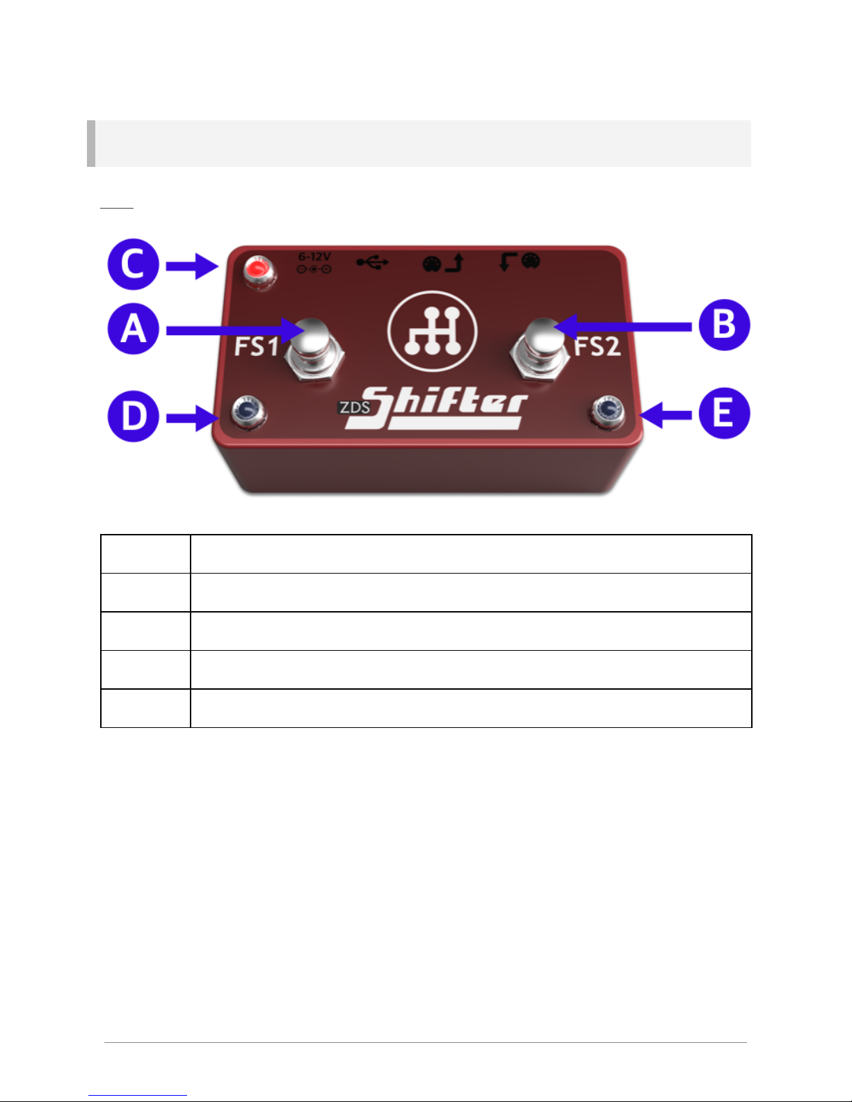
Physical Elements
Top
A
Footswitch #1
B
Footswitch #2
C
Power/activity light
D
Footswitch #1 indicator light
E
Footswitch #2 indicator light
© Nebiru Software, 2018 3
Page 5
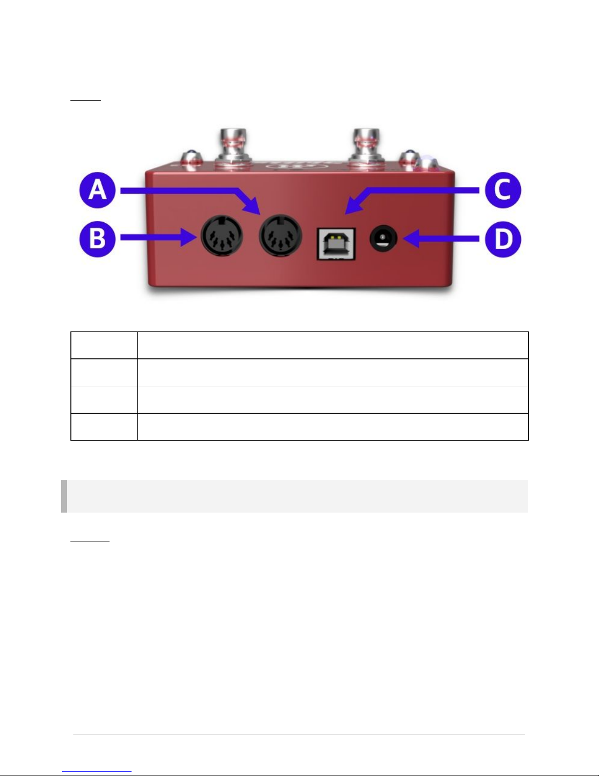
Back
A
MIDI Out/through
B
MIDI In (instrument)
C
USB (to computer)
D
DC Power connection. 6 to 12V, center positive
Hooking Things Up
Power
The Shifter can be powered by either the DC power jack or via USB.
Please be aware that the USB jack alone cannot reliably power your
Zendrum. If you need to send power to your Zendrum through the MIDI In
jack, then you’ll need to use the DC adaptor to provide the minimum 6 Volts
of power it requires.
You should use the power adapter provided with your Shifter, however, any
adaptor in the 6 to 12V range will work. Please be sure the adaptor you
© Nebiru Software, 2018 4
Page 6
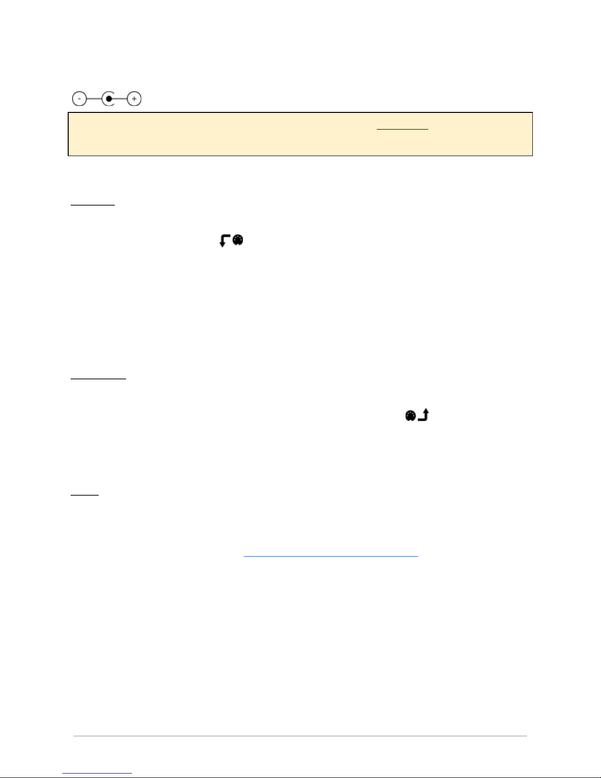
use is marked “center positive”, which generally is indicated by the symbol
Many 9V (and Roland/BOSS) adaptors are center negative, and should not
be used.
MIDI In
Connect your Zendrum or instrument to the MIDI In jack, which can be
identified by the symbol .
Take care when connecting non-Zendrum instruments as phantom power
is always delivered through the MIDI In jack. This typically won’t be a
problem for most devices as the two pins used to deliver power are usually
ignored.
MIDI Out
If your sound source requires a MIDI Din connection, then hook it up to the
Shifter’s MIDI Out connection, identified by the symbol . This jack also
doubles as a (soft) MIDI Thru port.
USB
The USB connector is used to connect the device to your computer if you
are using it as a sound source. The USB connection is also used to
program your device via the ZDS Shifter Web Application.
The USB port can also power the Shifter, however, it cannot also power
your Zendrum. If you are using wireless or are powering your Zendrum
from a battery or elsewhere, then powering the Shifter from the USB port
alone is perfectly fine.
© Nebiru Software, 2018 5
Page 7

Operation
Once programmed, you interact with the two footswitches to generate CC
messages or to enable/disable your shift rules. The two LEDs marked FS1
and FS2 turn on to indicate those foot switches are active. The power
LED also functions as the MIDI activity light and will flicker whenever MIDI
messages are detected.
Setting up Mappings
The Shifter supports ZenEdit style module mappings. These mappings are
used to display actual instrument names instead of MIDI note numbers and
make it more intuitive to program your Shifter.
The Shifter interface contains mappings for many popular sound modules
and VSTs. You may also import your own mappings (which you can export
from either ZenEdit or the Restomp application).
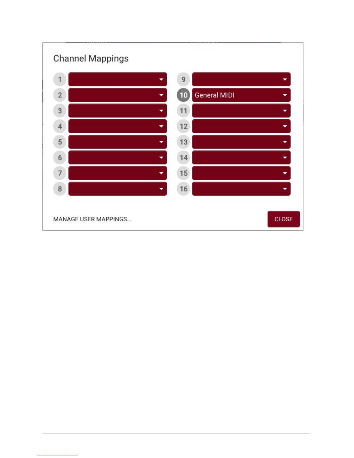
To set up your channel mappings, click on the link at the top of the group
grid. Initially, this link will display ‘General MIDI’ as this is the default
mapping used by the Shifter for MIDI channel 10 (drums). Clicking the link
will display the channel mapping interface where you can select which
module to use for each channel you care about.
© Nebiru Software, 2018 6
Page 8
To import your own mappings, click the button in the lower left labeled
‘Manage User Mappings’. This will display the list of mappings you’ve
imported (if any) and controls to import your own files.
The mapping you select for each MIDI channel is used in the shift rule grid
and ‘new rule’ dialogs to display the instrument name for Note ON and
Note Stack MIDI messages.
© Nebiru Software, 2018 7
Page 9

Programming the Shifter
Programming the Shifter requires that either Google Chrome or the Opera
web browser be installed.
Connect your Shifter to your computer using a USB cable and navigate to
the ZDS Shifter Web Application.
The application is split into two sections. The top section contains a visual
representation of your ZDS Shifter and is where you can set up how the
foot switches behave. The lower section is where you program your shift
rules. For convenience, these rules may be grouped into up to four
different groups, each of which can be controlled by a different CC
message.
Shift Rules
A shift rule works on a single message type and value. They have an input
and an output definition. The Shifter compares each MIDI message it
receives against the list of active shift rules. Any messages that match the
rule input are altered so that they match the output.
For a rule to be applied to a message, the input must match the message
type, channel and value.
The output of the rule can change some or all of these parameters.
Consider this example (utilizing BFD3):
© Nebiru Software, 2018 8
Page 10
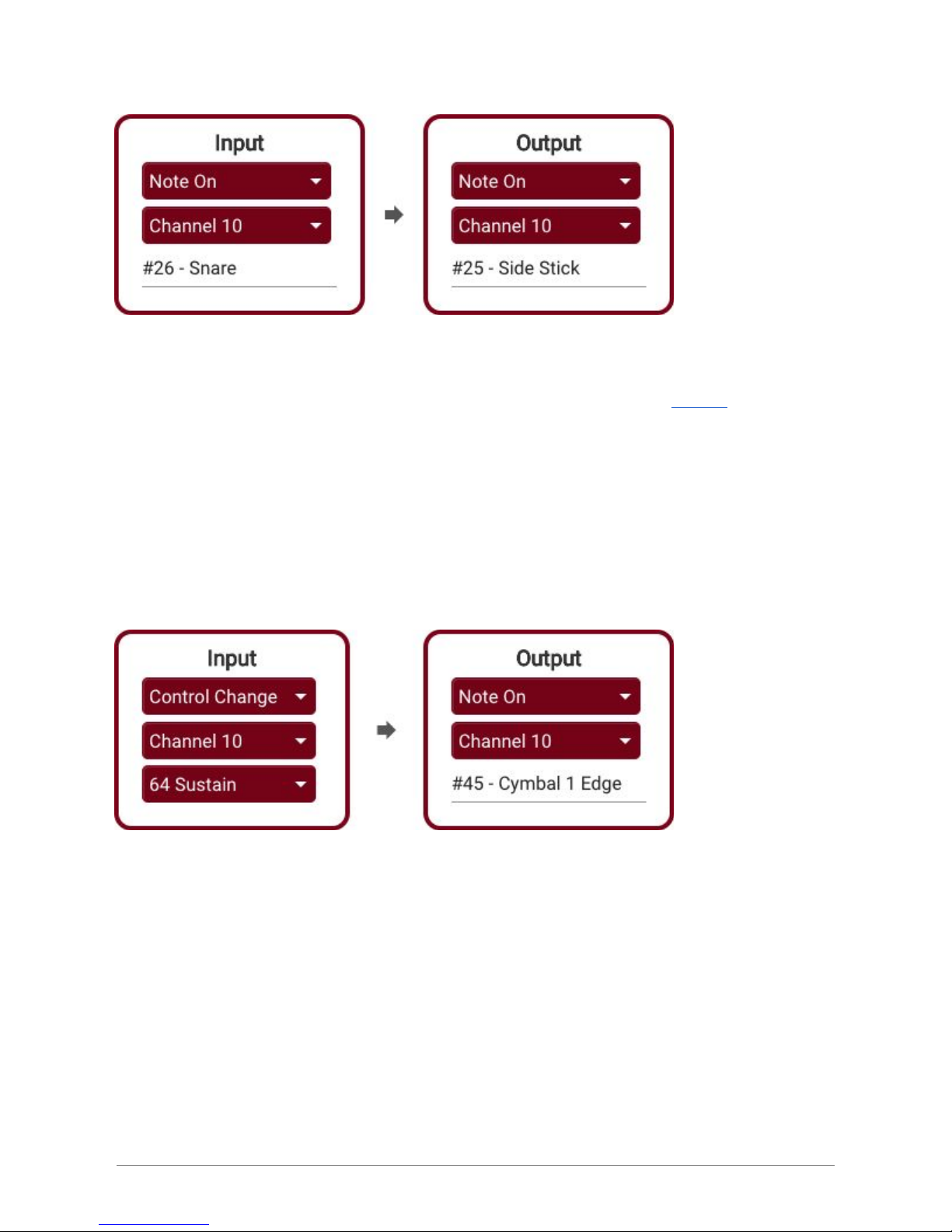
This rule states that any Note On message for snare hits (note #26) should
be replaced with cross stick hits (note #25), whenever the group CC is
active. (NOTE: you do not have to add an additional rule for Note Off -these are handled automatically)
Rules can be used to alter Note On messages like this, or they can be used
to completely alter the message type.
Consider the following:
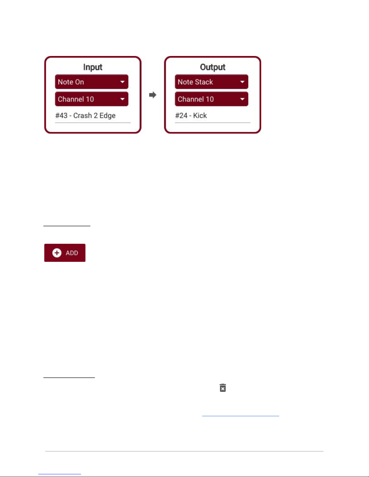
This rule will turn any CC #64 messages it sees into cymbal hits (the value
of the CC message becomes the velocity value for the hit).
Practically any MIDI message can be turned into another using shift rules.
Lastly, there is a new message type defined to handle note stacking.
Whenever the Input message type is Note On, then it is possible to select
‘Note Stack’ as the output type, and select an instrument name as in this
example:
© Nebiru Software, 2018 9
Page 11
Here we’re having the Shifter automatically play a kick drum sample
whenever a crash cymbal is hit. This effectively enables layer stacking for
any sound source!
Adding rules
Within each group tab is a button to add new rules.
Click this button to display the rule editor.
The rule editor is split into Input and Output sections. For each rule, the
Shifter listens for messages that match the defined Input and when it finds
any, it changes them to match the Output definition.
Deleting rules
At the far right of each rule is the delete button
The application will ask you for confirmation before removing the rule.
Deletions cannot be undone so be sure to backup your settings should you
need to recover them later.
© Nebiru Software, 2018 10
Page 12
Rule Groups
Your ZDS Shifter supports up to four rule groups which are represented
by the tabs in the interface, labeled ‘Group A’ through ‘Group D’.
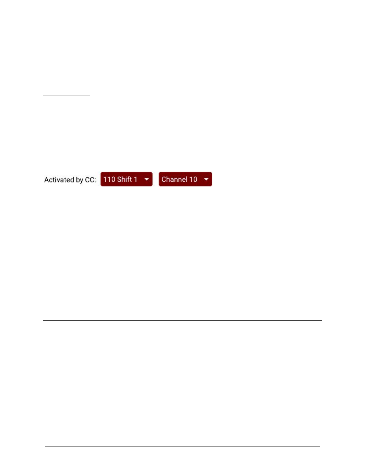
Each group is turned on/off by a specific CC message. These typically are
controlled by the footswitches and you’ll set the CC message and channels
to match.
Note however that the groups are not limited to responding only to the
footswitches. You could for instance setup the momentary switch on your
Zendrum to control one or more of the groups. So long as the groups see
a MIDI message appear for the CC message and channel it is listening
for, it will activate, regardless of what device generated it.
Be aware also that more than one group may be set up to respond to the
same CC message. How you distribute shift rules and arrange your
groupings is purely a matter of taste.
Controlling the power/activity LED
The power LED also doubles as a MIDI activity indicator. Its default mode
is to remain lit when power is present and to flicker when there is MIDI
activity. You can change the mode by opening the menu next to the LED
indicator.
© Nebiru Software, 2018 11
Page 13
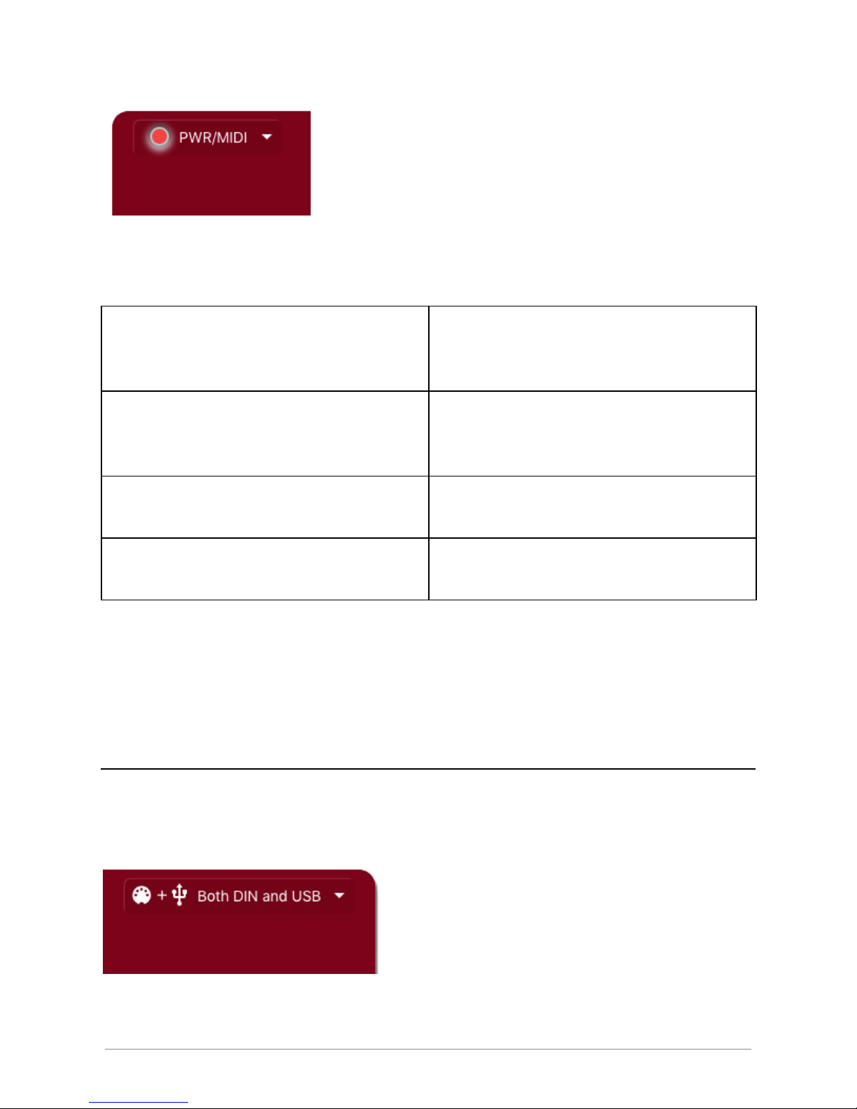
The available modes are as follows:
Flicker on activity; Normally ON
Default mode. The LED remains lit
as long as there is power. It will
flicker when there is MIDI activity.
Flicker on activity; Normally OFF
The LED will not light up when
there is power, however, it will
flicker when there is activity.
Always ON
The LED will always be lit when the
unit is powered up.
Always OFF
Disabled. The LED will not light
and will not flicker.
Experiment with these modes if you find the flickering or power light to be
distracting.
Controlling MIDI Out
Your Shifter will transmit MIDI on both the DIN and USB ports by default.
You can take control of which ports are used which will be helpful when
setting up complicated MIDI pathways.
© Nebiru Software, 2018 12
Page 14
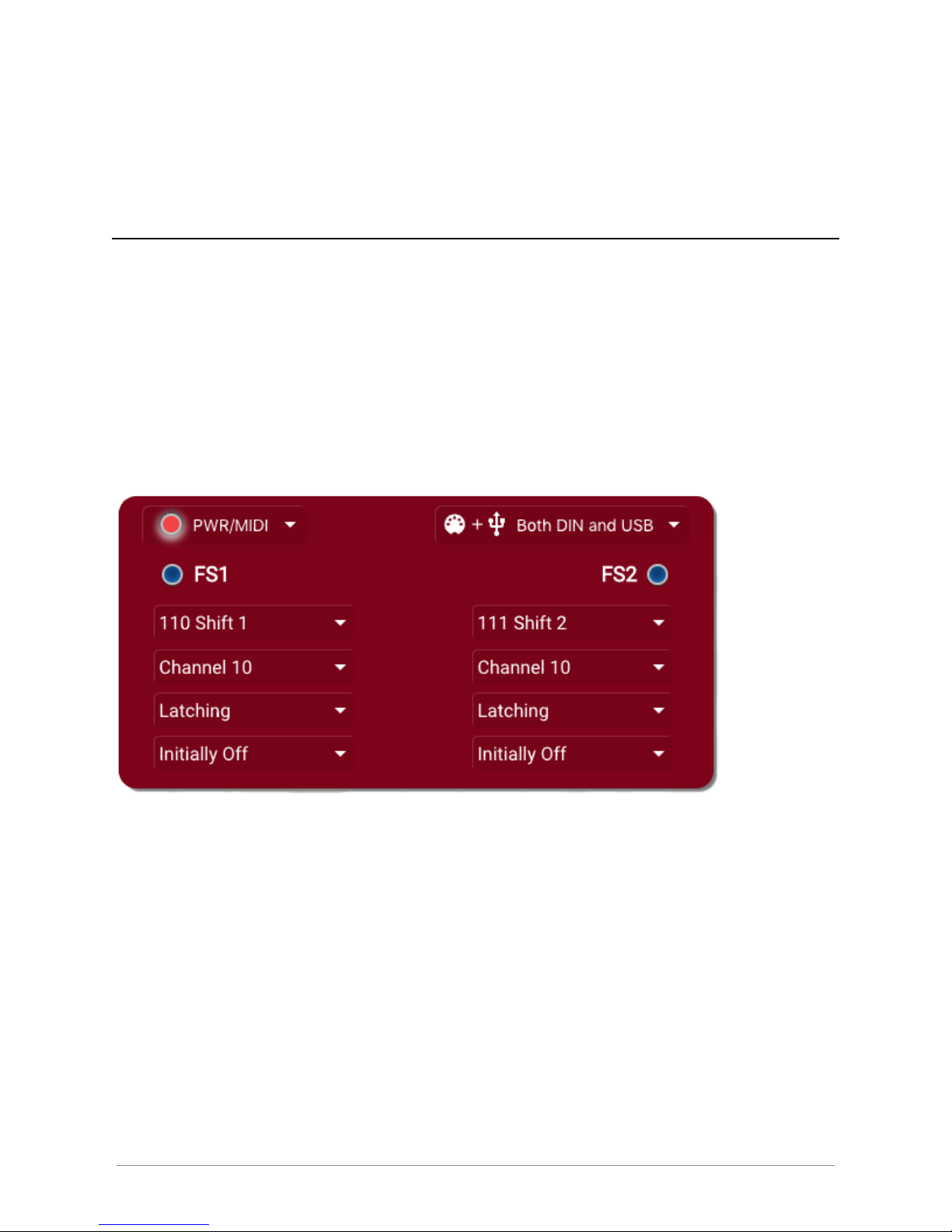
Use the menu to enable MIDI out on either the USB port, the DIN port or
both.
Footswitch Setup
Each footswitch is a programmable CC control. By changing the settings
associated with each switch, you can control which CC message is emitted
when you depress the footswitch, and how it toggles between enabled and
disabled states.
There are four settings for each footswitch you can set, all located at the
top half of the client application.
The first two settings are for the CC message and channel. By default,
the shifter associates the four shift groups with CC values 110 to 113
(labeled as ‘Shift 1’ to ‘Shift 4’) but you are free to choose any CC number
you wish. The channel also defaults to 10 (drums) but here again, you are
free to change the channel for either footswitch.
The third setting controls whether the footswitch will be ‘latching’ or
‘momentary’. When set to latching, the control will turn on when you
depress the footswitch once, and then turn back off when you step on it
© Nebiru Software, 2018 13
Page 15

again. A momentary switch is only on as long as the footswitch is
depressed, and turns off as soon as you lift your foot. Which you choose
will depend completely on your style of play and circumstances. If you
need to frequently switch between CC states, you may find that the
momentary action makes more sense. If on the other hand you only need
to change states once in a while or once per song, then the latching
behavior would be better suited.
The final setting for the footswitches is “polarity”. This controls whether
the CC starts off as enabled or disabled when the Shifter is turned on. The
default is ‘initially off’, meaning the CC will turn on when you depress the
switch. Alternatively, you can set this to ‘initially on’, meaning the CC
message will turn off when depressed. Which you choose is again
dependant on your needs and situation.
NOTE: The Shifter must reboot whenever the footswitches or power LED
settings are modified. The reboot is automatic but be aware that the
interface will go gray for a couple seconds while this is happening.
© Nebiru Software, 2018 14
Page 16
Backup and restore
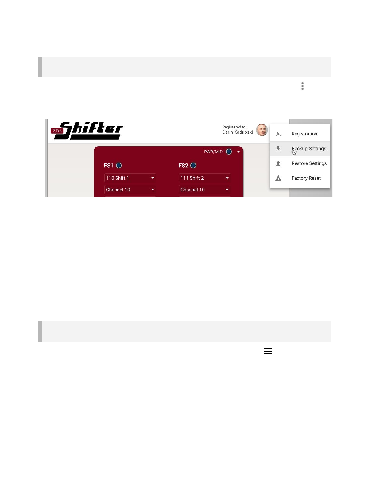
To access the backup and restore features, click on the menu icon in the
upper-righthand corner.
Choose ‘Backup Settings’ to download the internal state of your ZDS
Shifter. The ‘Restore Settings’ feature can later be used to reload those
saved settings. This is useful if you have created a complicated set of shift
rules and want to have your work backed up somewhere. It also is useful if
you use different sets of rules for different gigs or situations.
Factory Reset
Should you ever need to, you can click on the menu icon in the
upper-righthand corner of the application to access the ‘Factory Reset’
feature. This will erase all programmed shift groups and return the foot
switches and power LED to their factory default settings. This is not a
reversible action so be sure you have backed up your settings prior to
resetting.
© Nebiru Software, 2018 15
Page 17

The application will ask you to confirm this action before performing the
reset operation.
© Nebiru Software, 2018 16
 Loading...