


USER MANUAL
2019-03 0.2


DECLARATION OF CONFORMITY
The manufacturer
Neatech.it
Via A. de Curtis 4/A, 80040, Cercola (NA), Italy
declares that
the wheelchair EVO 1
(reference code: S045)
other names: EVO-1, EVO 1, EVO-1 FWD, EVO-1 RWD, EVO 1 FWD, EVO 1 RWD,
PEGASUS EVO 1
satisfies the requirements laid down by the European Directive 93/42;
according to the criteria for classification of Annex IX of this Directive, it is classified as:
class I medical device
It also complies with the requirement of the harmonized standards:
UNI EN 12182 – Technical aids for disabled person
UNI EN 12184 – Electrically powered wheelchairs, scooters and their chargers - Requirements
and test methods

Index
1 PRODUCT INFORMATION ....................................................................................................... 1
2 PREPARATION FOR FIRST USE ................................................................................................ 2
2.1 Checks to be made on delivery ....................................................................................... 2
2.2 Unpacking ........................................................................................................................ 2
2.1 Software description ....................................................................................................... 3
3 ADJUSTMENTS ........................................................................................................................ 4
3.1 List of adjustments .......................................................................................................... 4
3.2 Seat depth ........................................................................................................................ 5
3.3 Backrest angle .................................................................................................................. 7
3.3.1 Adjunctive backrest angle adjustment ................................................................... 10
3.4 Armrest depth ............................................................................................................... 12
3.5 Armrest height ............................................................................................................... 15
3.6 Sidepad height ............................................................................................................... 17
3.7 Footplates height ........................................................................................................... 19
3.8 Footplates depth and angle ........................................................................................... 22
3.9 Calf support position ..................................................................................................... 25
3.10 Legrest angle .............................................................................................................. 28
3.11 Joystick position ......................................................................................................... 30
3.11.1 Standard support - Depth ...................................................................................... 30
3.11.1 Retractable support - Depth and height................................................................ 31
3.12 Default position .......................................................................................................... 32
4 USE OF THE PRODUCT .......................................................................................................... 33
4.1 Control system of the wheelchair ................................................................................. 39
4.1.1 VR2 60 A control system ......................................................................................... 39
4.1.2 Rnet 80 A control system ....................................................................................... 40
4.2 Manual brake release lever ........................................................................................... 42
4.3 Use as seat in a motor vehicle ....................................................................................... 43
4.3.1 Four points tie-down .............................................................................................. 50
4.3.2 Dahl engineering docking station ........................................................................... 52
4.4 Powered functions ......................................................................................................... 54

4.5 Main switch ................................................................................................................... 56
4.6 Battery charging ............................................................................................................ 57
4.7 Transport and storage ................................................................................................... 59
5 MAINTENANCE ..................................................................................................................... 60
5.1 Maintenance and cleaning ............................................................................................ 60
5.2 Controls to be performed on the product..................................................................... 61
5.3 Tire puncture ................................................................................................................. 62
5.3.1 User information .................................................................................................... 62
5.4 Wiring diagram .............................................................................................................. 67
5.4.1 Rnet ......................................................................................................................... 67
5.4.2 VR2 .......................................................................................................................... 68
5.5 Reuse ............................................................................................................................. 69
5.6 Spare parts ..................................................................................................................... 70
5.6.1 Antitip wheels ......................................................................................................... 75
5.6.2 Cover A.................................................................................................................... 77
5.6.3 Cover B .................................................................................................................... 79
5.6.4 Levers for cover ...................................................................................................... 81
5.6.5 Lever for motors ..................................................................................................... 82
5.6.6 Standard joystick support ....................................................................................... 83
5.6.7 Retractable joystick support ................................................................................... 85
5.6.8 Joystick .................................................................................................................... 87
5.6.9 Legrest actuator ...................................................................................................... 88
5.6.10 Footplates ............................................................................................................... 90
5.6.11 Footplate fixing system .......................................................................................... 94
5.6.12 Backrest actuator .................................................................................................... 98
5.6.13 Backrest support ................................................................................................... 100
5.6.14 Backrest pin .......................................................................................................... 102
5.6.15 Axis for angle adjustable backrest ........................................................................ 103
5.6.16 Armrest padding ................................................................................................... 104
5.6.17 Armrest support ................................................................................................... 106
5.6.18 Armrest fixing system ........................................................................................... 108
5.6.19 Armrest lower support ......................................................................................... 110

5.6.20 Sidepad ................................................................................................................. 112
5.6.21 Legrest support ..................................................................................................... 113
5.6.22 Lever for angle adjustable legrest ........................................................................ 116
5.6.23 Calf support .......................................................................................................... 118
6 SPECIFICATIONS .................................................................................................................. 121
6.1 Maximum user weight ................................................................................................. 122
6.2 Other provided information ........................................................................................ 123
6.3 Dimensions .................................................................................................................. 125
7 WARRANTY TERMS ............................................................................................................. 126
7.1 Serial number .............................................................................................................. 126

Symbols in this manual
WARNING
This symbol means presence of danger for the user or damage for the
product. Always follow instructions when this symbol is present.
PINCH HAZARD
This symbol means presence of pinch hazard.
ELECTRICAL WARNING
This symbol means presence of danger related to the presence of electrical
energy. Please pay special attention when this symbol is present.
INFORMATION
This symbol means general information intended to simplify or best explain
the use of the product.
CONTACT INFORMATION
This symbol means the need of contacting an authorized service center or
the manufacturer.

TEMPERATURE
The temperature of some surfaces may increase when the product is
exposed to external heat sources as direct sunlight.
TIPPING HAZARD
Tipping hazard is strongly reduced because of the design of the product
according to EN 12182.
In any case, please pay special attention during the adjustments and use of
the product to prevent any damage to the user or product itself.
Any transport on a slope greater than the maximum safety slope can be
dangerous.
Please don’t seat on armrests.
ANTI-TIP DEVICES
Using anti-tippers substantially reduces your risk of falling over, which can
cause serious injury. The Anti-Tippers will keep you from falling over, but
they will limit your ability to be pulled up curbs and some other maneuvers.
IT IS NOT POSSIBLE TO HAVE THIS WHEELCHAIR WITHOUT ANTITIP
DEVICES.
Center of balance of the wheelchair and so its stability cab be affected by:
• User position
• Us of a backpack
• Tilting of the seat
PINCH HAZARD
Make sure your feet do not hang up or get caught in the space between the
footrests. In general, make sure you have proper space in areas you will
travel through to minimize pinching or entrapment of body parts.

ELECTROMAGNETIC RADIATION DANGER
The behavior of the wheelchair while driving may be affected by
electromagnetic fields created by transceivers such as: Citizens band (CB)
radios, walkie-talkies, fire and police radios, cellular phones, lap-top
computers, commercial radio and television broadcast antennas. PLEASE
USE CAUTION in the presence of these devices.
Electromagnetic radiation can cause your chair, without warning, to:
• release its brakes
• move by itself
• move in unintended directions
If any of these occur, it could result in severe injury to you or others.
Electromagnetic radiation can damage the control system of your chair.
There is no way to know the effect on electromagnetic immunity if you add
accessories or modify this chair. Any change to your chair may increase the
risk related to electromagnetic radiation. Parts from other suppliers have
unknown electromagnetic properties. The wheelchair might disturb the
operation of devices in its environment.
INFORMATION
For information on how to obtain information and instructions in a format
appropriate for use by visually impaired people please contact the
manufacturer.

Service manual is intended for technical personnel to maintain and repair wheelchairs. It is
important to follow the instructions contained in this manual in order to professionally work
with the product.
The qualified personnel who works with wheelchairs must comply with all provisions of
occupational safety and common sense in order to preserve his own safety.
The manufacturer declines all responsibility for any accidents occurring during the working with
the product.
WARNING: It is prohibited to use the product or its parts for any purpose other
than that indicated. For a correct use please follow the instructions given in this
manual. The manufacturer disclaims any responsibility for damages caused by
improper use of the product.
The manufacturer disclaims any responsibility for inappropriate selection of product model and
configuration.

Information in this manual may be subject to change without notice. All information, pictures and
specifications are based on the product details that were available at the time of preparation of this
document. They are representative examples and they are not intended to be exactly as the actual product.
MODIFICATIONS
Any unauthorized modification to the product may increase the risk of personal injury and damage to the
product itself. All modifications should be done by an authorized service center.
Do not use any unauthorized accessories or spare parts on the product. Do not use the product in
combination with other medical devices without first having considered any risk due to combination of
more products.
MANUFACTURER
For any need not expressly explained in this manual, please contact the manufacturer.
Neatech.it SRL
via A. de Curtis 4/A, 80040, Cercola (NA), Italy
www.neatech.it – info@neatech.it - +39 081 555 1946
INCIDENT REPORTING
If an incident occurs, please contact an authorized service center. For a list of authorized service center
please contact the manufacturer.
DISPOSING
This product and all its components can not be treated as household waste. For
more detailed information on how recycling and disposal this product contact your
local waste disposal service.

www.neatech.it
1/126
1 PRODUCT INFORMATION
Evo1 is a strong wheelchair, incredibly steady and made of high quality components for a
comfortable and safe driving performance anywhere you go.
Evo1 has a a minimal and well thought design, extremely compact and ideal for both indoor and
outdoor use, due to its small dimensions and the turning radius reduced to the minimum.
It is available with front or rear wheel drive and a wide range of options and alternative driving
systems.
The chassis is available in 2 sizes: small 49 cm and large 55 cm.
There is a choice of 16 colors, combinable so you can easily add a personal touch to the
wheelchair.
The modular seat structure is highly customizable, according to your own specific needs and it
can grow and develop together with the young user, with a wide range of interchangeable
support and positioning options.
Total wheelchair weight
Maximum user weight
MAX 125 kg
MAX 150 kg
Seat width
MIN 300 mm – MAX 460 mm
Batteries
Charger
Power module
Motors
2x 12 V 35 Ah / 2x 12 V 50 Ah
6 A
VR2 60 A / Rnet 80 A
2x 220 W

www.neatech.it
2/126
2 PREPARATION FOR FIRST USE
2.1 Checks to be made on delivery
• Check for the integrity of the original packaging.
• Check for any anomalies on shipping documents.
• Check for the functionality and integrity of the device in all its parts, at the time of delivery
or immediately thereafter, to ensure that no damage has resulted from a careless transport.
• Make sure the surface of the device is not damaged, scratched, bent, etc.
• Any fault or damage found must be immediately reported on the shipping documents and
promptly communicated to the shipper.
2.2 Unpacking
Inside the box there are:
• Evo1 wheelchair
• Documents and manual
• Charger
The wheelchair is delivered already mounted and ready to use. Before starting to use the
wheelchair please check if all described components are present. If not, please contact as soon
as possible the vendor.
PACKAGING DISPOSAL
To properly recycle the packaging materials follow instructions provided
by your local waste disposal service.
www.neatech.it
3/126
2.1 Software description
The wheelchair, according to specific configuration, can be equipped with Rnet system or VR2
system.
The software of the wheelchair can be categorized into these classes:
• Kernel software of power module.
There is no required access, modification or customization of this part of the software
In case a reprogramming of the wheelchair is required, please contact the
manufacturer to have instructions and the most suitable version of the
software.
In case of problems with this part of the software please contact the
manufacturer.
• Software parameters of the wheelchair.
This part of the software is made by the manufacturer. It is intended to assure driving and
seating function of the wheelchair. It is responsibility of the manufacturer to correct program
parameters regarding the structure of the wheelchair.
Qualified personnel of an authorized service center are able to customize this part of the
software to best fulfill single user requirements.
Programming must be conducted only by qualified personnel with indepth knowledge of the wheelchair and power module system.
Any change to this part of the software may result in a hazardous situation
for the user.

www.neatech.it
4/126
3 ADJUSTMENTS
3.1 List of adjustments
Type of operation
A
Operation intended to be performed by the user.
B
Operation intended to be performed by an assistant.
C
Operation intended to be performed by an authorized
service center.
Table 1
Adjustment
Type of operation
Seat depth
B - Assistant
Backrest angle
B - Assistant
Armrests depth
B - Assistant
Armrests height
B - Assistant
Sidepad height
B - Assistant
Footplates height
B - Assistant
Footplates angle and depth
B - Assistant
Joystick position
B - Assistant
Calf support position
B - Assistant
Legrest angle
B - Assistant
Table 2

www.neatech.it
5/126
3.2 Seat depth
WHEELCHAIR
SIZE
(A)
MIN
VALUE
(A)
MAX
VALUE
M1 - S045-V067
300 mm
420 mm
M2 - S045-V068
340 mm
460 mm
M3 - S045-V069
380 mm
440 mm
M3 - S045-V070
440 mm
500 mm
M4 – S045-V071
400 mm
460 mm
M4 – S045-V072
460 mm
520 mm
M5 – S045-V073
460 mm
520 mm
Table 3
WARNING
It is needed to set separately left and right seat depth. Always set them at
the same manner.
Average needed
time:
5 min
Difficulty level:
Easy
A

www.neatech.it
6/126
Figure 1
• Remove the backrest.
• Loosen the 6 screws shown in figure.
• Repeat operations for both left and right side of the
wheelchair.
• Set the backrest according to the desired seat depth.
• Tight again the 6 screws.
• Repeat operations for both left and right side of the
wheelchair.
• Mount again the backrest.
OPEN-END WRENCH
10 mm

www.neatech.it
7/126
3.3 Backrest angle
BACKREST
CONFIGURATION
(A)
POSSIBLE
VALUES
Angle adjustable with fixed
position
90° or 110°
95° or 115
100° or 120°
105° or 125°
110° or 130°
115° or 135°
Angle adjustable with
pistons
See section
3.3.1
Powered backrest
90° - 130°
WARNING
It is needed to set separately left and right backrest angle. Always set two
parts of backrest at the same manner.
Average needed
time:
5 min
Difficulty level:
Easy
Powered legrest
• Act on the joystick as described in section 4.1.
Angle adjustable with pistons
Use the lever located on the push bar to move the backrest.
A

www.neatech.it
8/126
Angle adjustable with fixed position
Figure 2
• Unscrew the 4 screws shown in figure.
• Repeat operations for both left and right side of the
wheelchair.
• Set the position of the hardware highlighted in
figure according to the desired backrest angle.
• Screw again screws.
• Repeat operations for both left and right side of the
wheelchair.
OPEN-END WRENCH
10 mm

www.neatech.it
9/126
ADDITIONAL ADJUSTMENT
After adjusted the angle of backrest as described above it is possible to
adjust of more 20° simply acting on the axis shown in figure.
Figure 3

www.neatech.it
10/126
3.3.1 Adjunctive backrest angle adjustment
WARNING
This section refers only to angle adjustable backrest with pistons.
WARNING
It is needed to set separately left and right backrest angle. Always set two
parts of backrest at the same manner.
Average needed
time:
5 min
Difficulty level:
Easy
BACKREST
CONFIGURATION
(A)
POSSIBLE
VALUES
Angle adjustable with
pistons
90° - 130°
95° : 130°
100° : 135°
105° : 135°
110° - 140°
120° - 145°
A

www.neatech.it
11/126
Figure 4
• Unscrew the 4 screws shown in figure.
• Repeat operations for both left and right side of the
wheelchair.
• Set the position of the hardware highlighted in
figure according to the desired backrest angle.
• Screw again screws.
• Repeat operations for both left and right side of the
wheelchair.
OPEN-END WRENCH
10 mm

www.neatech.it
12/126
3.4 Armrest depth
RANGE
It is not easy to provide a range for adjustment of armrests depth because
there are too many configuration and possibilities.
RIGHT AND LEFT SIDE
It is possible to adjust separately left and right side.
Average needed
time:
<5 min
Difficulty level:
Easy
RANGE
Please be sure that the chosen position doesn't represent an obstacle.
Figure 5

www.neatech.it
13/126
Figure 6
• Loosen the lever shown in figure and remove the
armrest.
Figure 7
• Unscrew the lever shown in figure.
• Loosen the 2 screws shown in figure and set the
depth of armrest clamp as desired.
• Tighten again the 2 screws and put back the armrest.
ALLEN WRENCH
4 mm

www.neatech.it
14/126
ADDITIONA ADJUSTMENT
Moreover it is possible to adjust armrest depth unscrewing the 2 screws
shown in figure with a 4 mm allen wrench.
Figure 8

www.neatech.it
15/126
3.5 Armrest height
WHEELCHAIR
SIZE
(A)
MIN
VALUE
(A)
MAX
VALUE
S045-V401
200 mm
270 mm
S045-V402
260 mm
340 mm
RIGHT AND LEFT SIDE
It is possible to adjust separately left and right armrest.
Average needed
time:
<5 min
Difficulty level:
Easy
SIDEPAD, JOYSTICK AND ARMREST HEIGHT
It is better to adjust first armrest height, then joystick and finally the
sidepad.
A

www.neatech.it
16/126
Figure 9
• Loosen the 2 screws shown in figure.
• Set the armrest according to the desired height.
• Tight again the 2 screws.
ALLEN WRENCH
4 mm

www.neatech.it
17/126
3.6 Sidepad height
RANGE
It is not easy to provide a range for adjustment of sidepad because there are
too many configuration and possibilities.
RIGHT AND LEFT SIDE
It is possible to adjust separately left and right sidepad.
SIDEPAD, JOYSTICK AND ARMREST HEIGHT
It is better to adjust first armrest height, then joystick and finally the
sidepad.
Average needed
time:
<5 min
Difficulty level:
Easy
www.neatech.it
18/126
RANGE
Please be sure that the chosen position doesn't represent an obstacle for
armrest.
Figure 10
Figure 11
• Unscrew the 2 screws shown in figure and set the
position of sidepad as desired.
• Screw again the 2 screws.
ALLEN WRENCH
3 mm

www.neatech.it
19/126
3.7 Footplates height
LEGREST
CONFIGURATION
(A)
POSSIBLE
VALUES
Fixed angle
150 mm
175 mm
200 mm
225 mm
250 mm
275 mm
300 mm
325 mm
350 mm
375 mm
400 mm
Angle adjustable
150 mm
175 mm
200 mm
225 mm
250 mm
275 mm
300 mm
325 mm
350 mm
375 mm
Central mounted legrest
165 mm
185 mm
205 mm
225 mm
245 mm
265 mm
285 mm
305 mm
325 mm
345 mm
365 mm
385 mm
Powered legrest
255 mm
280 mm
305 mm
330 mm
355 mm
380 mm
A

www.neatech.it
20/126
RIGHT AND LEFT SIDE
It is possible to adjust separately left and right legrest if you have splitted
footrest.
INFORMATION
With calf supports, it is possible that some footplates heights can't be
reached.
Average needed
time:
<5 min
Difficulty level:
Easy
Figure 12
• Unscrew the screw shown in figure with the allen
wrench while holding the nut behind with the open-
end wrench.
• Repeat the operation for both left and right side of
the wheelchair.
• Set the position of the footplate according to
desired height.
• Screw again the screws.
ALLEN WRENCH
5 mm
OPEN-END WRENCH
13 mm

www.neatech.it
21/126
Central mounted legrest
Figure 13
• Unscrew the screw shown in figure with the allen
wrench while holding the nut behind with the open-
end wrench.
• Set the position of the footplate according to
desired height.
• Screw again the screws.
ALLEN WRENCH
5 mm
OPEN-END WRENCH
13 mm

www.neatech.it
22/126
3.8 Footplates depth and angle
RANGE
It is not easy to provide a range for adjustment of footrests because there
are too many configuration and possibilities. In any case it is always possible
to choose between 3 different depth.
RIGHT AND LEFT SIDE
It is possible to adjust separately left and right legrest if you have splitted
footrest.
Average needed
time:
<5 min
Difficulty level:
Easy

www.neatech.it
23/126
Angle adjustment
Figure 14
• Loosen the 2 screws shown in figure.
• Set the position of the footplate according to desired angle.
• Tighten again the screws.
ALLEN WRENCH
4 mm
Central mounted legrest
Figure 15
• Loosen the screw shown in figure to lower the footplate. Tighten
it to rise the footplate.
ALLEN WRENCH
4 mm

www.neatech.it
24/126
Depth adjustment
Figure 16
• Unscrew the 2 screws shown in figure.
• Set the position of the footplate according to desired depth.
• Screw again the screws.
ALLEN WRENCH
4 mm
Central mounted legrest
RANGE
It is not possible to perform this adjustment with central mounted legrest.

www.neatech.it
25/126
3.9 Calf support position
RANGE
It is not easy to provide a range for adjustment because there are too many
configuration and possibilities.
RIGHT AND LEFT SIDE
It is possible to adjust separately left and right side.
Average needed
time:
<5 min
Difficulty level:
Easy
Figure 17
• Unscrew the 2 screws shown in figure and set the
position of calf support as desired.
• Screw again the 2 screws.
ALLEN WRENCH
4 mm

www.neatech.it
26/126
ADJUNCTIVE ADJUSTMENT
Moreover it is possible to choose the angle of calf support simply by pulling
or pushing it.
Figure 18
Central mounted legrest
Figure 19
• Unscrew the screw shown in figure and set the
height of calf support as desired.
• Screw again the 2 screws.
ALLEN WRENCH
6 mm

www.neatech.it
27/126
Figure 20
• Loosen the screw shown in figure using a allen
wrench and a open-end wrench.
• Set the angle ad desired and tighten again the
screw.
ALLEN WRENCH
6 mm
OPEN-END WRENCH
13 mm

www.neatech.it
28/126
3.10 Legrest angle
LEGREST
CONFIGURATION
(A)
POSSIBLE
VALUES
Fixed angle
70°
Angle adjustable
20° - 90°
Central mounted
10° - 90°
Powered legrest
-15° - 80°
Angle adjustable
Average needed
time:
<1 min
Difficulty level:
Easy
Figure 21
• Loosen the lever shown in figure.
• Set legrest angle as desired.
• Tighten again the lever.
A

www.neatech.it
29/126
Powered legrest
• Act on the joystick as described in section 4.1.
PINCH HAZARD
Please pay special attention when moving legrest because there is the
possibility of trapping your or someone else fingers in legrest mechanism.
Figure 22
Central mounted legrest
Figure 23
• Loosen the lever shown in figure.
• Set legrest angle as desired.
• Tighten again the lever.

www.neatech.it
30/126
3.11 Joystick position
RANGE
It is not easy to provide a range for this because there are too many
configuration and possibilities.
Average needed
time:
<5 min
Difficulty level:
Easy
3.11.1 Standard support - Depth
Figure 24
• Unscrew the 2 screws shown in figure.
• Adjust the depth of the joystick as desired.
• Screw again the screws.
ALLEN WRENCH
5 mm

www.neatech.it
31/126
ADJUNCTIVE ADJUSTMENT
Moreover it is possible to adjust the angle of the joystick simply acting on
the two levers shown in figure.
Figure 25
3.11.1 Retractable support - Depth and height
Figure 26
• Unscrew the 2 screws shown in figure.
• Adjust the depth and the height of the joystick as
desired.
• Screw again the screws.
ALLEN WRENCH
5 mm

www.neatech.it
32/126
3.12 Default position
Default position means that all adjustable parts of the wheelchair are set in the most stable and
safe configuration
ADJUSTABLE PARTS
VALUE
NOTES
Seat angle
0°
Backrest angle
90°
Legrest angle
90°
Or minimum
Seat height
0 cm
Table 4

www.neatech.it
33/126
4 USE OF THE PRODUCT
WARNING
Do not operate the wheelchair if it is behaving abnormally or erratically.
The wheelchair may come to a sudden stop at any time during operation.
WARNING
Do not stand on the product. Always use caution when transferring in or out
of the seat. Every precaution should be taken to reduce the transfer
distance. Also be certain the wheel locks are engaged to prevent the wheels
from moving.
Do not let children use the wheelchair without supervision.
INFORMATION
The product is not intended to be dismantled. There are no parts of the
product expected to be handled during normal use of it
INFORMATION
Do not install, maintain or operate the product without reading all warnings
and this entire manual.
Always keep this manual in connection with the product.
INFORMATION
The wheelchair is designed for use mostly in indoor environments.
www.neatech.it
34/126
DRIVE WITH SEATING SYSTEM NOT IN DEFAULT POSITION
Seat tilt, backrest recline or legrest elevation may varies the center of
gravity of the system wheelchair + user and increase tipping risk.
Always drive at low speed when the seating system is not in the standard
position and use powered seating functions only on a flat horizontal
surface.
WARNING
Do not carry passengers on the wheelchair independently of the age of the
passenger. The wheelchair is not designed for weight training and is unsafe
for use as a seat while weight training. Do not lean over the top of the back
upholstery to reach objects from behind as this may cause the wheelchair
to tip over. Do not shift your weight or sitting position toward the direction
you are reaching as the wheelchair may tip over. Do not stand on the frame
of the wheelchair.
Some pathologies may limit your ability to use your wheelchair safely. Be
sure to consult with a doctor about your physical limitations.
Please practice your drive ability under the supervision of an assistant.

www.neatech.it
35/126
Dealing with uphill
When facing an uphill road it is recommended to set the seating system to default position. It is better to use
a drive profile with low speed.
Figure 27
Dealing with downhill
When facing a downhill road it is recommended to set the seating system to default position. It is better to
use a drive profile with low speed
Figure 28
MAX 6°
MAX 6°

www.neatech.it
36/126
WARNING
Don’t use the wheelchair up or down slopes with a gradient than indicated
in specifications of this manual.
Don’t use the wheelchair up or down ramps that are not equipped with
proper edge protection to prevent the wheelchair from falling down.
Don’t use the wheelchair down or up a hazardous incline if the surface is
covered with snow, ice or the surface is uneven.
WARNING
The stopping distance on slopes can be significantly greater than on level
ground
Dealing with side slopes
When facing with side slopes, always use the wheelchair with great caution and make sure the seating system
is in the default position.
Figure 29
Turning with the wheelchair
When turning with the wheelchair, always use great caution.
MAX 6°

www.neatech.it
37/126
Obstacle climbing
When facing with an obstacle, always use great caution and make sure the seating system is in
the default position. The wheelchair is able to climb an obstacle of 50 mm with a run up of
minimum 500 mm.
Figure 30
Driving in dark environments
Don't use the wheelchair in dark environments without lights turned on.
Pelvic belt
The wheelchair has the predisposition for a pelvic belt. Pelvic belt is only design to position the
user and not for any protection in case of accident.
Transfer into and out the wheelchair
Users transfer is recommended with the presence of an assistant. Don’t use footrests or
armrests as support. Always turn off the wheelchair before transfer.

www.neatech.it
38/126
Lift of the wheelchair
Do not lift the wheelchair with a user on board. Do not lift the wheelchair grabbing the legrests.
If you really need to lift the wheelchair, it is suggested to grab it with the help of at least one
other people. Grab the wheelchair using the tie down shown in figure.
Figure 31

www.neatech.it
39/126
4.1 Control system of the wheelchair
It is possible to have the wheelchair with VR2 60 A control system or Rnet 80 A control system.
4.1.1 VR2 60 A control system
Figure 32
FUNCTION
DESCRIPTION
On-Off
Use this function to turn on and off the
wheelchair. Don't use this function to stop
the wheelchair unless it is an emergency.
Horn
MODE
Use this function to navigate between drive
and seat function.
Speed increase/decrease

www.neatech.it
40/126
4.1.2 Rnet 80 A control system
Figure 33
FUNCTION
DESCRIPTION
On-Off
Use this function to turn on and off the
wheelchair. Don't use this function to stop
the wheelchair unless it is an emergency.
Horn
MODE
Use this function to navigate all working
mode of the wheelchair. For example it is
possible to choose between drive and seat
function.
PROFILE
As default in the wheelchair they are saved
some different drive profile for the use indoor
and outdoor.
Use the function PROFILE to change different
types of profiles: they are sorted from the
more indoor ones to the more outdoor ones.
For each profile it is possible to change the
speed.
Speed increase/decrease

www.neatech.it
41/126
Activate at the same time the functions to increase and decrease speed to enter a configuration
menu.
FUNCTION
DESCRIPTION
Set time
Use this function to set the time shown on the
display.
Distance
Use this function to see total and partial
distance made with the wheelchair. It is also
possible to reset partial distance.
Backlight
It is possible to adjust backlights of the
screen.
Background
Use this function to choose the color of
background of the display.

www.neatech.it
42/126
4.2 Manual brake release lever
In case of necessity it is possible to manually move the wheelchair.
First of all, you have to turn off the wheelchair.
Then you can act on the release lever shown in Figure.
When the brakes are released. it is not possible to drive the wheelchair.
Figure 34
UNLOCKED
LOCKED
LOCKED
UNLOCKED
WARNING
When the brakes are released never use the wheelchair on a slope or a wet
surface.
Don’t operate the brake release without the presence of an assistant.
WARNING
The drive system should be re-engaged before an occupant is left
unattended or attempts to operate the wheelchair.
WARNING
Always act on both left and right manual release levers.

www.neatech.it
43/126
4.3 Use as seat in a motor vehicle
The wheelchair is designed to be secured facing forward when used as a seat in a motor vehicle and it
complies with the requirements of ISO 7176-19:2008.
It is possible to use four-point strap systems or the DAHL docking station.
Ease of access to, and maneuverability in, motor vehicle can be significantly affected by wheelchair size
and turning radius. Smaller wheelchairs or with a shorter turning radius will generally provide greater ease
of vehicle access and maneuverability to a forward- facing position.
Always use ISO 10542-1 approved Wheelchair Tiedown and Occupant Restraint Systems, which are
suitable for the weight of the wheelchair or Dahl docking.
Wheelchair users should transfer to the vehicle seat and use the vehicle-manufacturer-installed restraint
systems whenever it is feasible and the unoccupied wheelchair should be stored in a cargo area or secured
in the vehicle during the travel.
For the correct positioning of occupant belt restraints on the user, please consider following.
• The pelvic belt should be worn low across the front of the pelvis, so that the angle of the
pelvic belt is within the preferred zone of 30° to 75° to the horizontal, similar to that
shown in figure.
Figure 35

www.neatech.it
44/126
• Belt restraints should be adjusted as tightly as possible, consistent with user comfort.
• Belt should not be twisted during the use.
IMPROPER BELT RESTRAINT FIT
BELT RESTRAINTS MUST NOT BE HELD AWAY
FROM THE BODY BY WHEELCHAIR
COMPONENTS SUCH AS ARMRESTS OR
WHEELS
PROPER BELT RESTRAINT FIT
BELT RESTRAINTS SHOULD MAKE FULL
CONTACT WITH THE SHOULDER, CHEST AND
PELVIS AND PELVIC BELTS SHOULD BE
POSITIONED LOW ON THE PELVIS NEAR THE
THIGH ABDOMINAL JUNCTION
Figure 36
In order to mount pelvic belt on the wheelchair, firstly
mount the fixing plate as shown in figure.
Use socket head cap screw M6x10 and a 5 mm allen
wrench.
Repeat operation for both left and right side of the
wheelchair.
ALLEN WRENCH
5 mm

www.neatech.it
45/126
Figure 37
In order to mount chest belt on the wheelchair, firstly
mount the fixing plate as shown in figure.
Use socket head cap screw M6x10 DIN 912 and a 5 mm
allen wrench.
Repeat operation for both left and right side of the
wheelchair.
ALLEN WRENCH
5 mm
Figure 38
Moreover, chest belt must be fixed in the upper part of
the backrest. Firstly mount the fixing plate as shown in
figure.
Use hushroom head square neck bolt screw M5x16 DIN
603, M5 nut, and a 8 mm open-end wrench.
Repeat operation for both left and right side of the
wheelchair.
OPEN-END
WRENCH
8 mm

www.neatech.it
46/126
WARNING
The seating system must be set in the DEFAULT POSITION when used in a
motor vehicle. Particularly be sure that the seat is horizontal, legrest are
completely down and backrest is completely up. For more information see
section 3.12.
WARNING
Evo3 wheelchair has lots of configurations and accessories. The wheelchair
safety when used as a seat in a motor vehicle is assured by the
manufactured if the specific configuration is mentioned in the order form
and if all instructions in the manual are followed. Particularly it may exist
some options or accessories that are not compatible with the use of the
wheelchair as a seat in a motor vehicle, or it may exist some accessories
that require some precautions.
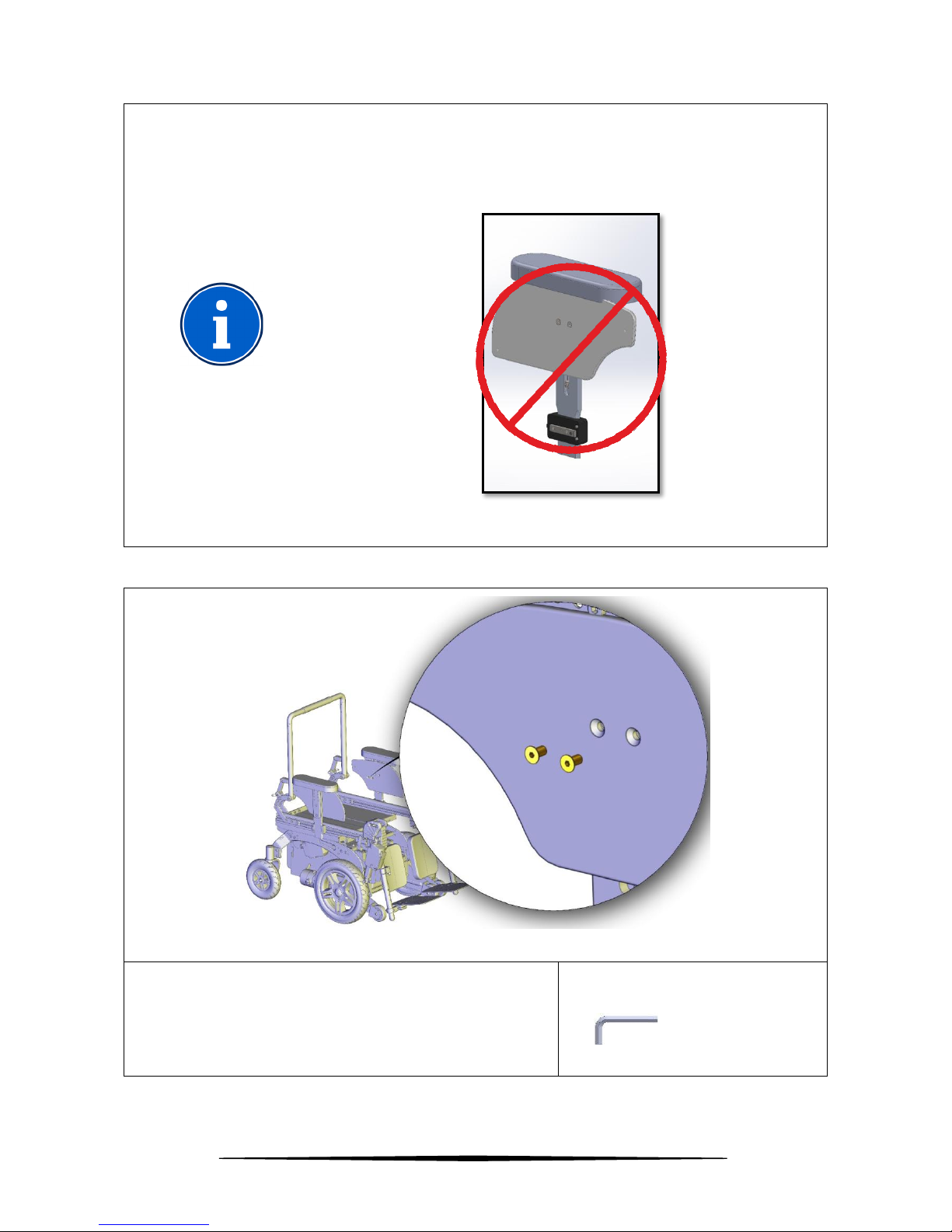
WARNING
If the backrest is with gas springs, when using the wheelchair as a seat in
a motor vehicle, it is necessary to lock the movement of the gas springs
with the locking system shown in the picture. Always repeat the operation
for the left and right side of the wheelchair. WARNING: Safety of
wheelchair and user can't be assured when the movement of gas springs
is not correctly locked while using the wheelchair as a seat in a motor
vehicle.
Figure 39

www.neatech.it
47/126
WARNING
The wheelchair complies with the requirements of ISO 7176-19:2008 and
has been designed and tested for use only as a forward-facing seat in a
motor vehicle.
Compliance with this standard does not preclude using the wheelchair
facing rearward in large accessible vehicles such as autobus.
WARNING
The wheelchair has been dynamically tested in a forward facing orientation
with the ATD restrained by both pelvic and shoulder belts.
WARNING
Both pelvic and shoulder belt should be used to reduce the possibility of
head and chest impacts with vehicle components.
WARNING
In order to reduce the potential of injury to vehicle occupants wheelchair
tray should be removed and secured separately in the vehicle.
WARNING
When possible other auxiliary wheelchair equipment should be either
secured to the wheelchair or removed from the wheelchair and secured in
the vehicle during travel, so that it does not break and cause injury to vehicle
occupants in the event of a collision.

www.neatech.it
48/126
WARNING
You should not use this product in a motor vehicle if your weight is less than
22 kg.
WARNING
Postural supports should not be relied on for occupant restraint in a moving
vehicle unless they are labelled as being in accordance with the
requirements specified in ISO 7176-19:2008.
WARNING
The wheelchair should be inspected by a manufacturer's representative
before reuse following involvement in any type of vehicle collision.
WARNING
Alterations or substitutions should not be made to the wheelchair
securement points or to structural and frame parts or components without
consulting the wheelchair manufacturer.
WARNING
Wheelchair has sealed type batteries. Never use different battery type when
used in a motor vehicle.

www.neatech.it
49/126
WARNING
Care should be taken when applying the occupant restraint to position the
seatbelt buckle so that the release button will not be contacted by
wheelchair components during a crash.
www.neatech.it
50/126
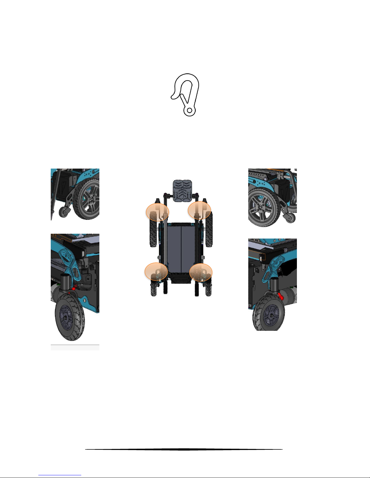
4.3.1 Four points tie-down
Use the tie down points marked with the symbol shown in figure.
Figure 40
Use the tie down points marked with the symbol shown in figure. Hook the wheelchair in 4
points: two in the front part and two in the rear part.
Figure 41

www.neatech.it
51/126
Tie down straps should form angles shown below.
PREFERRED ANGLES OF FRONT
WHEELCHAIR TIE DOWN STRAPS
Figure 42
PREFERRED ANGLES OF REAR WHEELCHAIR
TIE DOWN STRAPS
Figure 43
WARNING
Always use four tie down straps.
40°
60°
300
mm
25°
25°
45°
30°
10°
10°
300
mm

www.neatech.it
52/126
4.3.2 Dahl engineering docking station
WARNING
Please be sure that the vehicle is equipped with a fully working and
compatible Dahl docking system.
Figure 44
• To use the system, maneuver the wheelchair slowly and in a uniform direction over the
docking station. The lock plate under the wheelchair helps to guide the wheelchair into place
in the docking station. When the lock plate is fully engaged in the docking station, a spring-
action locking pin automatically secures the lock plate.
• The docking station is equipped with a control switch that indicates whether the lock plate
is correctly secured in the docking station. As soon as the lock plate comes into contact with
the locking pin, a warning tone will sound and the red led in the control panel will light up
until the lock plate is either fully engaged or else the wheelchair is removed from the docking
station. As an indication that the wheelchair is properly secured, the warning tone will cease,
the red diode in the control panel will go out and the green led will light up.
• When the wheelchair is correctly secured, the safety belt should be fitted and adjusted so
that it fits the user.
• UNLOCKING PROCEDURE. When the vehicle has been brought to a halt, remove the safety
belt. To unlock commence by driving the wheelchair forward to release pressure on the lock
pin and then press the red release button in the control panel. The locking pin will be
triggered/released for approx 5 seconds, after which the locking pin is automatically
locked/activated again. Do not attempt to reverse out the docking station until the red LED
on the control module, which indicates the unlock position, has been illuminated. Move the
wheelchair away from the docking station within this 5-second period.

www.neatech.it
53/126
WARNING
Attempting to reverse the wheelchair before the red LED has been
illuminated will result in blocking the docking station lock mechanism
which makes it impossible to reverse. If this happens repeat above
unlocking procedure.
Figure 45
CONTACT INFORMATION
For more information contact the manufacturer of the wheelchair or the
manufacturer of the docking station.
Dahl Engineering
Løvevej 3
DK-7700 Thisted
Tel. +45 96 18 00 77
https://dahlengineering.dk
sales@dahlengineering.dk

www.neatech.it
54/126
4.4 Powered functions
WARNING
Operating these functions changes the center of gravity and increases the
risk of tipping over.
Always drive in low speed when the seating system is not in the default
position. Use these functions only on horizontal plane.
To enter seating mode use MODE function of the joystick.
With VR2 system a led will turn on to indicate the seat function in use.
With Rnet system a wheelchair will appear on the screen of the joystick.
To select the desired function move the joystick left or right.
The number and the type of available function may change according to the specific
customization of each wheelchair.
MOVE UP
Move the joystick forward
while you are in seating mode
and the desired function is
selected
MOVE DOWN
Move the joystick rearward
while you are in seating mode
and the desired function is
selected
BACKREST
Move forward the backrest
Recline the backrest
LEFT LEGREST
Low left legrest
Elevate left legrest

www.neatech.it
55/126
RIGHT LEGREST
Low right legrest
Elevate right legrest
LEGRESTS BOTH
Low both legrests
Elevate both legrests
TILT
Move forward the seat
Tilt the seat
LIFT
Rise the seat
Lower the seat

www.neatech.it
56/126
4.5 Main switch
Use the main switch to connect and disconnect the batteries from the power module.
The switch also has the function of protecting the wheelchair from overloaded current and short
circuit.
OFF
ON
Figure 46
Figure is taken having the wheelchair on the front and shows the position ON and OFF of the
switch.
If the power chair suddenly stops, use the switch to connect again batteries to the power
module and turn on again the wheelchair. If the problem still continues, it means that there is
some electric fault.
If the switch operates, often this means that there is a major electrical
fault. The cause of fault should be checked carefully.
For more information, please contact the manufacturer.

www.neatech.it
57/126
4.6 Battery charging
In order to recharge batteries, use only the provided charger or one recommended by the
manufacturer. The manufacturer is not responsible for any damage to person or objects
resulting from the use of non-original product.
CHARGER SPECIFICATION
24 V -MIN 6 A MAX 10 A - Charge profile for AGM batteries
• Connect the power cord to a power supply 230 V.
• Connect the cable to the joystick as shown in Figure.
VR2
RNET
Figure 47
• When batteries are loaded unplug the power cord and the battery cable from the joystick.
RUNNING-IN PERIOD
Typically, batteries are able to offer 100% performance after about 15-20
cycles.
BATTERIES SPECIFICATION
Seat width from 300 mm to 360 mm: 24 V - 35 Ah - about 197x131x180 (h)
mm - about 11 kg
Seat width from 380 mm to 460 mm: 24 V - 50 Ah - about 198x166x171 (h)
mm - about 15 kg

www.neatech.it
58/126
WHEN AND HOW IT IS NECESSARY TO CHARGE BATTERIES?
It is very important to charge batteries every day, even if they are not
completely discharged. Each battery is subject to a normal self-discharge,
so batteries that are not used for long time will discharge by itself.
It is very important to don’t let batteries uncharged for long time.
It is very important to complete every cycle of charging
Charging time is influenced by multiple factors such as remaining battery
power, battery state of aging and temperature. However, the approximate
charging time is about 12 hours.
Battery charging should be done in well ventilated environments. Never
charge in bathroom or wet room.
When the charger is connected it is not possible to drive the wheelchair.
Don’t use the wheelchair during the charge.
SHOCK HAZARD
Check if charger requirements data matches with the network power
(voltage, frequency)
RELEASE DANGER
Any impact to the batteries could cause a loss of fluids. Please pay special
attention.
BATTERIES DISPOSAL
To properly recycle the batteries follow instructions provided by your local
waste disposal service.

www.neatech.it
59/126
4.7 Transport and storage
If you are not willing to use the wheelchair for a long period, keep it safe in a clean area and
away from heat.
If it is necessary to transport the wheelchair to facilitate operation follow these instructions.
It is possible to store the wheelchair in a place with a temperature between -20 °C and +45 °C.
• Turn off the wheelchair.
• Turn off the main switch. See section 4.5.
WARNING
If you transport the wheelchair with motors disengaged, the wheelchair is
free to move. This may result in a hazardous situation.

www.neatech.it
60/126
5 MAINTENANCE
Please remind that the wheelchair is intended exclusively for the carriage of seated people.
Below there are some precautions for the use of the wheelchair, which it is recommend to
follow, in order to ensure a safe use and a long duration.
Regular maintenance helps to keep intact the functionality and safety of the wheelchair.
Inadequate or lack of care and maintenance may cause a limitation of the warranty.
• Avoid prolonged contact of the wheelchair with water. It may cause oxidation of the metal
parts.
• Avoid long exposure of the wheelchair to direct sunlight.
WARNING
Any work on the wheelchair must be performed by an authorized service
center.
INFORMATION
It is not possible to perform any maintenance on batteries. It is only possible
to substitute them.
5.1 Maintenance and cleaning
To clean the wheelchair do not use high-pressure water spray devices. For plastic and metal
parts use a soft cloth dampened with mild detergent. For the upholstery, linings, seat and back
covers use warm water and mild detergent. Do not use stain removers, solvents, acids, etc.

www.neatech.it
61/126
5.2 Controls to be performed on the product
Type of operation
A
Operation intended to be performed by the user.
B
Operation intended to be performed by an assistant.
C
Operation intended to be performed by an authorized
service center.
Operation
Frequency
Type of operation
Check if motors are correctly
locked. See section 4.2.
Before each use
B - Assistant
Check that no wires are in the way
for the movements of the chair
Before each use
B - Assistant
Check the charge of batteries
Daily
A - User
Clean the wheelchair
Weekly
B - Assistant
Check if the pressure is the one
indicated on tires and in section 6
Traction wheels: 280 kPa; Castors:
250 kPa.
Weekly
B - Assistant
Check if the lever of the main
switch works correctly
Weekly
B - Assistant
Check tire usury
Monthly
B - Assistant
Check brake release lever
Monthly
B - Assistant
Check aging of batteries
Monthly
C - Service

www.neatech.it
62/126
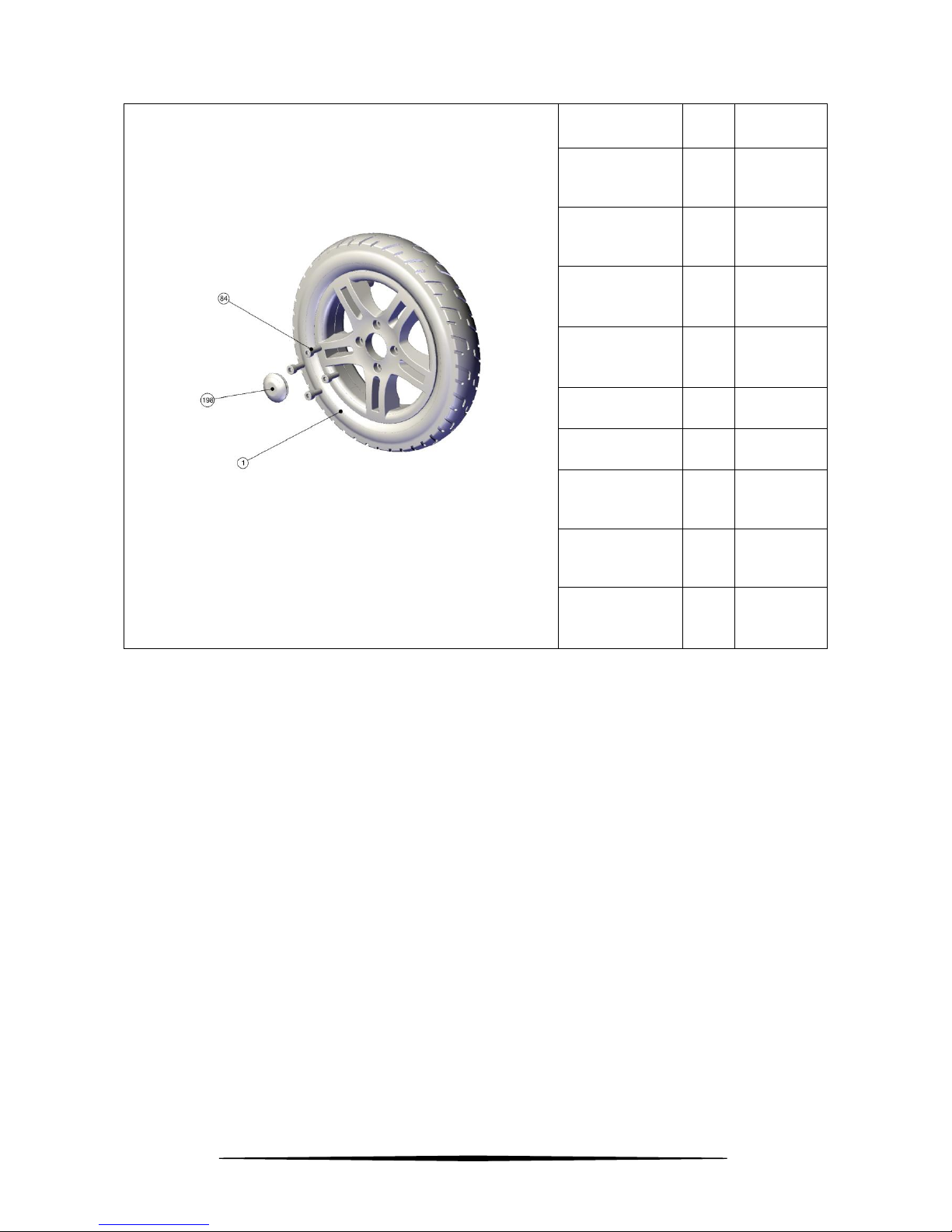
5.3 Tire puncture
5.3.1 User information
Traction wheel
Figure 48
• Lift the wheelchair.
• Unscrew the 4 screws shown in figure.
• Remove the wheel.
ALLEN WRENCH
6 mm

www.neatech.it
63/126
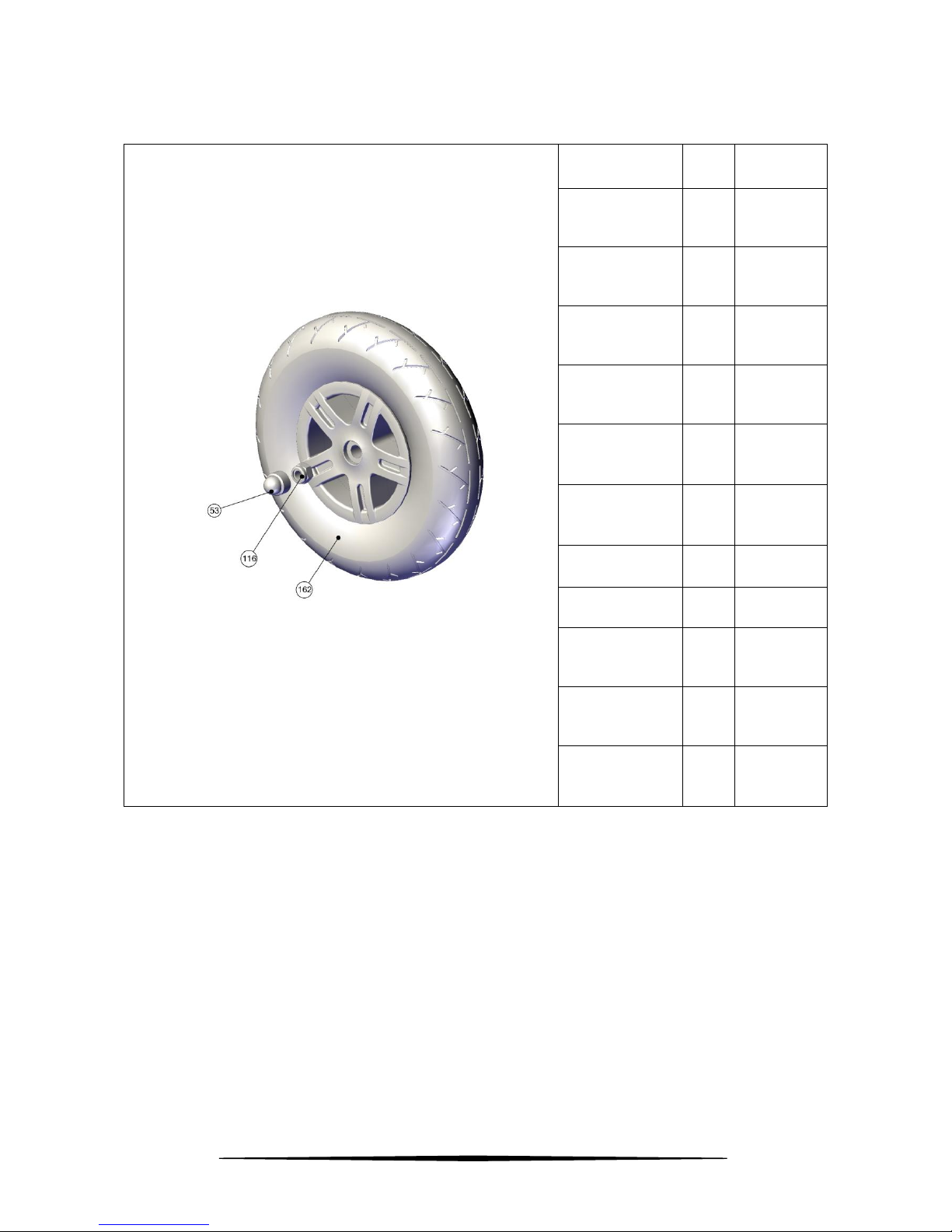
Castors wheel
Figure 49
• Lift the wheelchair.
• Unscrew the nut shown in figure.
• Remove the castor.
OPEN-END WRENCH
10 mm
Contact an authorized service center for the repair or the substitution of the
damaged wheel. When the authorized service center gives you back the
repaired wheel or a new one, mount it following instructions in reverse
order.

www.neatech.it
64/126
Code
Description
Type of
operation
R045-0120A
Traction wheel Pneumatic Gray Ø320x58 mm
A
R045-0120B
Traction wheel Pneumatic Black Ø320x58 mm
A
R045-0121A
Tire of traction wheel gray Ø320x58 mm
B
R045-0121B
Tire of traction wheel black Ø320x58 mm
B
R045-0122
Tube of traction wheel Ø320 mm
B
R045-0131A
Castor Pneumatic gray Ø200 mm x 50 mm
A
R045-0131B
Castor Pneumatic black Ø200 mm x 50 mm
A
R045-0131C
Castor PU gray Ø200 mm x 50 mm
A
R045-0131D
Castor PU black Ø200 mm x 50 mm
A
R045-0132A
Tire of castor gray Ø200 mm x 50 mm
B
R045-0132B
Tire of castor black Ø200 mm x 50 mm
B
R045-0133
Tube for castor Ø200 mm x 50 mm
B
Table 5
Type of operation
A
Parts that can be bought at an authorized service center
and substitute autonomously
B
Parts that need to be substituted at an authorized service
center.
www.neatech.it
65/126
Figure 50
Code
ID
Quantity
R045-0120A
1A
tire
1
R045-0120B
1B
tire
1
R045-0120
1
rim
1
R045-0120
1
tube 1 R045-0120
198 1 R045-0120
84
4
R045-121A
1A
tire
1
R045-121B
1B
tire
1
R045-0122
1
tube
1
www.neatech.it
66/126
Figure 51
Code
ID
Quantity
R045-0131A
162A
tire
1
R045-0131B
162B
tire
1
R045-0131C
162C
tire
1
R045-0131D
162D
tire
1
R045-0131A
162
tube
1
R045-0131B
162
tube 1 R045-0131
53 1 R045-0131
116
1
R045-0132A
162A
tire
1
R045-0132B
162B
tire
1
R045-0133
162
tube
1

www.neatech.it
67/126
5.4 Wiring diagram
5.4.1 Rnet
Figure 52

www.neatech.it
68/126
5.4.2 VR2
Figure 53

www.neatech.it
69/126
5.5 Reuse
The product is suitable for reuse. Before dispensing it, the product must be cleaned, and
subjected to maintenance. The operating instructions are included in this manual and must also
be provided when the product is passed on.
WARNING
This operation must be performed only at an authorized service center.

www.neatech.it
70/126
5.6 Spare parts
Type of operation
A
Parts that can be bought at an authorized service center
and substitute autonomously
B
Parts that need to be substituted at an authorized service
center.
Table 6
Code
Description
Type of
operation
Notes
R045-0110A
Batteries 35 Ah
B
R045-0110B
Batteries 50 Ah
B
R045-0120A
Traction wheel Pneumatic Gray Ø320x58 mm
A
R045-0120B
Traction wheel Pneumatic Black Ø320x58 mm
A
R045-0121A
Tire of traction wheel gray Ø320x58 mm
B
R045-0121B
Tire of traction wheel black Ø320x58 mm
B
R045-0122
Tube of traction wheel Ø320 mm
B
R045-0131A
Castor Pneumatic gray Ø200 mm x 50 mm
A
R045-0131B
Castor Pneumatic black Ø200 mm x 50 mm
A
R045-0131C
Castor PU gray Ø200 mm x 50 mm
A
R045-0131D
Castor PU black Ø200 mm x 50 mm
A
R045-0132A
Tire of castor gray Ø200 mm x 50 mm
B
R045-0132B
Tire of castor black Ø200 mm x 50 mm
B
R045-0133
Tube for castor Ø200 mm x 50 mm
B
R045-0134
Fork B

www.neatech.it
71/126
R045-0135
Bearings
B
R045-0140
Antitip wheel
A
R045-0150
Cover A A
R045-0160
Cover B A
R045-0161
Levers for cover
A
R045-0170
Motors - couple
B
R045-0171
Lever for motors
A
R045-0180
Main switch
B
R045-0181
Lever for main switch
A
R045-0190A
Standard joystick support
A
R045-0190B
Retractable joystick support
A
R045-0200A
Joystick Rnet
A
R045-0200B
Joystick VR2
A
R045-0210A
Power module Rnet
B
R045-0210B
Power module VR2
B
R045-0220
Seat module Rnet
B
R045-0230
Charger A
R045-0313
Legrest actuator
A
R045-0320A
Footplates splitted - seat width 300 mm
A
R045-0320B
Footplates splitted - seat width 340 mm
A
R045-0320C
Footplates splitted - seat width 380 mm
A
R045-0320D
Footplates splitted - seat width 420 mm
A
R045-0320E
Footplates splitted - seat width 460 mm
A

www.neatech.it
72/126
R045-0320F
Footplate unique - seat width 300 mm
A
R045-0320G
Footplate unique - seat width 340 mm
A
R045-0320H
Footplate unique - seat width 380 mm
A
R045-0320J
Footplate unique - seat width 420 mm
A
R045-0320K
Footplate unique - seat width 460 mm
A
R045-0321A
Fixing system for footrest - LEFT side unique
footplate
A
R045-0321B
Fixing system for footrest - RIGHT or LEFT side
splitted footplates or RIGHT side unique
footboard
A
R045-0321C
Fixing system for footrest - central mounted
legrest
A
R045-0330A
Tilt actuator 30°
B
R045-0330B
Tilt actuator 45°
B
R045-0330C
Tilt actuator (with lift + 45° tilt system)
B
R045-0340
Lift actuator
B
R045-0360
Backrest actuator
A
R045-0371
Backrest support (4 pieces)
A
R045-0372
Gas spring for tilting - couple
B
R045-0373
Backrest pin
A
R045-0374
Axis for angle adjustable backrest
A
R045-0380
Padding for push handle
A
R045-0391
Armrest padding
A
R045-0392
Armrest support
A
R045-0393
Armrest fixing system
A

www.neatech.it
73/126
R045-0394
Lever for armrest
A
R045-0395A
Armrest lower support standard
A
R045-0395B
Armrest lower support high
A
R045-0396
Sidepad A
R045-0400
Legrest support
A
R045-0401
Lever for legrest
A
R045-0402A
Lever for angle adjustable legrest - standard
legrest
A
R045-0402B
Lever for angle adjustable legrest - central
mounted legrest
A
R045-0403
Plastic cover for powered legrest
B
R045-0404A
Calf support SMALL
A
R045-0404B
Calf support LARGE
A
R045-0404C
Calf support for central mounted legrest
SMALL
A
R045-0404D
Calf support for central mounted legrest LARGE
A
R045-0420
Gyroscope
B
Table 7
WARNING
The use of spare parts or accessories not approved by the manufacturer may
make the wheelchair unstable or uncontrollable.
For each order, always contact an authorized service center.

www.neatech.it
74/126
CONTACT INFORMATION
For any other part not described in this manual please contact the
manufacturer.

www.neatech.it
75/126
5.6.1 Antitip wheels
Average needed
time:
5 min
Difficulty level:
Easy
Figure 54
• Unscrew the screws shown in figure.
• Substitute the wheel.
• Screw the new screws.
SCREWDRIVER

www.neatech.it
76/126
Figure 55
Code
ID
Quantity
R045-0140
1 1 R045-0140
2
2
Code
Description
Type of
operation
Notes
R045-0140
Antitip wheel
A

www.neatech.it
77/126
5.6.2 Cover A
Average needed
time:
5 min
Difficulty level:
Easy
Figure 56
• Unscrew the 4 screws shown in figure.
• Substitute the cover.
• Screw the new screws.
ALLEN WRENCH
3 mm

www.neatech.it
78/126
Code
Description
Type of
operation
Notes
R045-0150
Cover A
A
Figure 57
Code
ID
Quantity
R045-0150
229
1
R045-0150
108
4

www.neatech.it
79/126
5.6.3 Cover B
Average needed
time:
5 min
Difficulty level:
Easy
Figure 58
• Unscrew the 4 screws shown in figure.
• Substitute the cover.
• Screw the new screws.
ALLEN WRENCH
3 mm

www.neatech.it
80/126
Code
Description
Type of
operation
Notes
R045-0160
Cover B
A
Figure 59
Code
ID
Quantity
R045-0160
367
1
R045-0160
366
4
R045-0161
365
2

www.neatech.it
81/126
5.6.4 Levers for cover
Average needed
time:
5 min
Difficulty level:
Easy
Figure 60
• Substitute the levers shown in figure.
Code
Description
Type of
operation
Notes
R045-0161
Levers for cover
A

www.neatech.it
82/126
5.6.5 Lever for motors
Average needed
time:
5 min
Difficulty level:
Medium
Figure 61
• Unscrew the screw shown in figure.
• Substitute the levers for motor.
• Screw the new screw.
ALLEN WRENCH
4 mm
Code
Description
Type of
operation
Notes
R045-0171
Lever for motors
A
Figure 62
Code
ID
Quantity
R045-0171
365
1
R045-0171
367
1

www.neatech.it
83/126
5.6.6 Standard joystick support
Average needed
time:
5 min
Difficulty level:
Easy
Figure 63
• Unscrew the 2 screws shown in figure.
• Remove the joystick.
ALLEN WRENCH
4 mm
Figure 64
• Unscrew the 2 screws shown in figure. Unscrew the 2
screws shown in figure.
• Substitute the joystick support.
• Mount the old joystick following instructions in
reverse order.
ALLEN WRENCH
5 mm

www.neatech.it
84/126
Code
Description
Type of
operation
Notes
R045-0190A
Standard joystick support
A
Figure 65
Code
ID
Quantity
R045-0190 A
76
1
R045-0190 A
107
2
R045-0190 A
114
2
R045-0190 A
336
1
R045-0190 A
337
1
R045-0190 A
338
1
R045-0190 A
339
1
R045-0190 A
340
1
R045-0190 A
341
1
R045-0190 A
342
1
R045-0190 A
348
1

www.neatech.it
85/126
5.6.7 Retractable joystick support
Average needed
time:
5 min
Difficulty level:
Easy
Figure 66
• Unscrew the 2 screws shown in figure.
• Remove the joystick.
ALLEN WRENCH
3 mm
Figure 67
• Unscrew the 2 screws shown in figure.
• Substitute the joystick support.
• Mount the old joystick following instructions in
reverse order.
ALLEN WRENCH
3 mm

www.neatech.it
86/126
Code
Description
Type of
operation
Notes
R045-0190B
Retractable joystick support
A
Figure 68
Code
ID
Quantity
R045-0190B
63
1
R045-0190B
64
1
R045-0190B
65
4
R045-0190B
107
2
R045-0190B
114
2
R045-0190B
118
8
R045-0190B
373
4

www.neatech.it
87/126
5.6.8 Joystick
Average needed
time:
5 min
Difficulty level:
Easy
Standard joystick support
Figure 69
• Unscrew the 2 screws shown in figure.
• Substitute the joystick.
ALLEN WRENCH
4 mm
Retractable joystick support
Figure 70
• Unscrew the 2 screws shown in figure.
• Substitute the joystick support.
ALLEN WRENCH
3 mm

www.neatech.it
88/126
Code
Description
Type of
operation
Notes
R045-0200A
Joystick Rnet
A
R045-0200B
Joystick VR2
A
5.6.9 Legrest actuator
Average needed
time:
5 min
Difficulty level:
Easy
Figure 71
• Remove the seegers shown in figure. Use a
screwdriver as a lever.
• Unplug cable of actuator.
• Substitute the actuator.
SCREWDRIVER
Code
Description
Type of
operation
Notes
R045-0313
Legrest actuator
A

www.neatech.it
89/126
Figure 72
Code
ID
Quantity
R045-0313
86
1
 Loading...