

Page 1

ARP AVATAR PATCH PANEL
INSTRUCTION MANUAL
Page 2

Introduction
Thank you for purchasing an Avatar Patch Panel Kit! These instructions are intended to guide you through installing and using this kit.
Before we get started, let’s go over a few guidelines:
Never open the Avatar or perform any service on it when the unit is
plugged in to AC power. Take your time when drilling in to the front
panel and when making cuts to traces on the circuit boards. Careless
work can damage your instrument and diminish its resale value. This
work should be performed by persons experienced with electronics
and mechanical construction. This modication is considered advanced and should not be undertaken by the novice. Please consider
hiring a professional technician or engineer to do this work if you are
not comfortable. This kit will take 8-10 hours for an experienced tech-
nician to install
Kit Contents
• Polycarbonate Graphic Panel
• (2) Potentiometers
• Two Knobs (both black.)
• Heat Shrink Tubing
• (2) 50 pin IDC cables
• (2) PCBs, 1 x Left Panel, 1 x Right Panel
• (36) 1/8” Switching Jacks
• (36) 3/8” Mounting Nuts
• (1) 1M Resistor
• (2) 50-Pin IDC Connectors
Page 3

Tools Required For Installation
• Electric Drill
• 5/16” Drill Bit
• 3/8” Drill Bit
• Center Punch
• Wire cutters
• Wire strippers
• Solder
• Soldering Iron
• Dremel or Exact-O Knife
• 1/4”Socket Driver
• 3/8” Socket Driver
• Phillips Head Screwdriver
• Heat Gun or Hair Dryer
Positioning, Marking, and Drilling of Panel
The vinyl New England Analog adhesive panel overlay is used as a
template for marking and drilling the ARP Avatar front panel.
Line up the graphics horizontally and adjust vertically so the top edge
of the vinyl overlay just meets the orange front panel graphic under
the LFO Repeat switch. The bottom edge of the vinyl overlay should
be approximately 33mm from the bottom edge of the Avatar front
panel. Secure in position with removable tape taking care not to obstruct the holes in the overlay.
Accurately mark the center of the openings, remove the overlay, and
drill the VCO1 glide and VCO2 glide locations to 3/8” and all other
holes to 5/16”. Deburr the holes on both sides of the panel. If drilling
the panel by hand, cover the internal components adequately with a
dropcloth and use a sharp center punch to prep each drilling location
to minimize the drill bit wandering. If using a drill press, remove the
circuit boards from the front panel and remove the panel from the
case. Wooden spacer blocks will be needed under the panel to level it
while drilling.
Page 4

Figure 1A - Alignment of Overlay
Figure 1B - Alignment of Overlay
Page 5
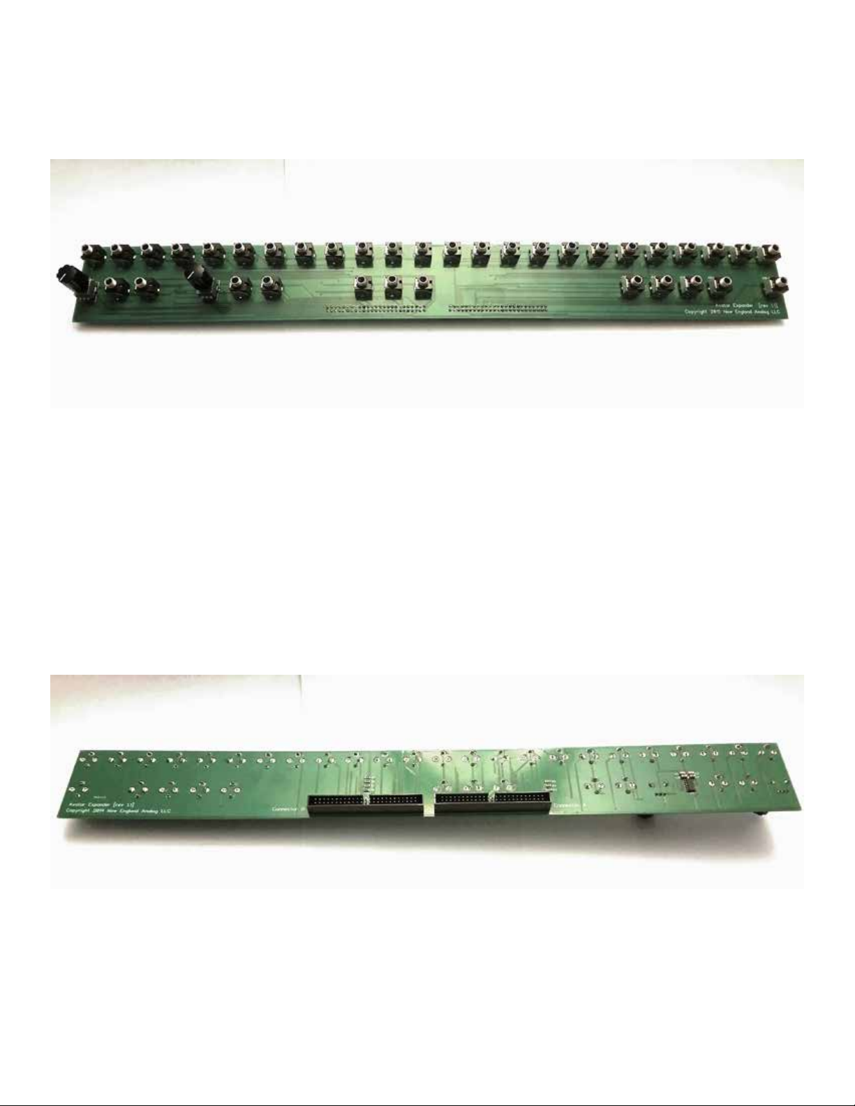
Assembled PCB (Top View)
Assembled PCB (Bottom View)
Page 6

Panel Mounting and PCB Mounting
Before afxing the vinyl overlay to the Avatar panel, dry t and verify
the alignment of the overlay, panel holes, and patch board hardware,
securing the jack hardware only loosely in place. Inaccurately drilled
panel holes may result in a slight buckling or misalignment of the
overlay which can be remedied by slightly enlarging the misaligned
holes. The vinyl overlay has a strong adhesive, so use care in afxing
it to the panel.
Attach the 36 1/8” switching jacks and pots to the top of the PCB.
Attach IDC connectors to the bottom of the PCB. Pay close attention
to the keying of the IDC connectors as well. Pin 1 is always marked
on the IDC header with either a 1 or a triangle pointing to pin 1. Make
sure you know which pin is pin 1 (brown wire) before you start wiring. IDC Header A is on the left side of the PCB (contains VCOs, S&H,
etc) and Header B is on the right side (VCF, VCA, Envelopes.)
Electrical Modications and Connections
Several conductive traces must be cut (electrically open) on the Avatar
circuit boards. This is best done with a rotary tool such as a Dremel
but can also be accomplished with a sharp utility or hobby knife.
The following pages have diagrams of the circuit boards to be modi-
ed. There are certain conventions that must be followed when using
the diagrams. A cut to the PCB is indicated with a yellow line. Each
cut will require that a wire be tack soldered on to each side of the cut.
A trace that does not need to be cut, but still has a wire attached to it
will be indicated with a yellow dot. A wire will be needed on the oscillator board, and it is indicated by a purple line.
The diagrams have a letter and a number indicating which wires
should be soldered to each point. The letter A indicates that a wire is
on the left front panel PCB cable. The letter B indicates that the wire
is in the right front panel PCB cable. There are 50 wires on each cable. The red wire indicates pin 1. For example, A12 would mean wire
12 on the left front panel PCB cable. Trim the wires in the cables to
the lengths needed to reach the point on the PCB where they will be
soldered.
Page 7

A1
A2
A3
A4
A11
A12
A13
A15
A14
A16
Figure 2.
Board B Top Left
Page 8

A26
A31
A32
A28
A15
A16
A23
A24
A25
A27
A33
A34
Figure 3.
Board B Top Center
Page 9

Figure 4.
Board B Top Right
A30
Page 10

A5
A6
Wire
Figure 5.
Board B Bottom Left
A18
A17
Figure 6.
Board B Bottom Center
Page 11

A9, A10
A35, A36, A39
A40, A43, A44
A47, A48
A7, A8,
A19, A20
A21, A22
Figure 7.
Board B Bottom Right
Page 12
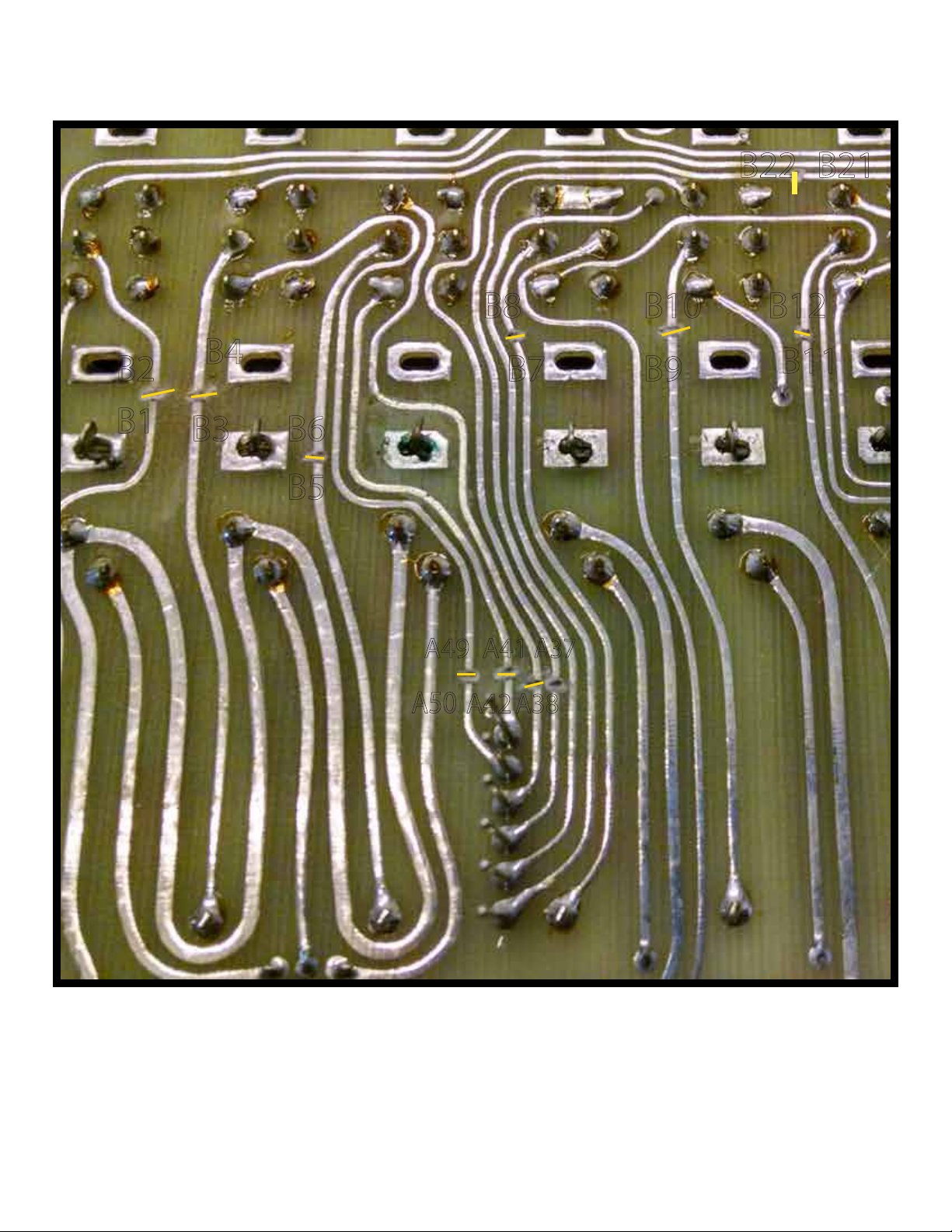
B21B22
B2
B1
B4
B3 B6
B5
A49
A50
B8 B10
A41
A42
B7
A37
A38
B9
B12
B11
Figure 8.
Board C Top Left
Page 13

B23,24
B19
B27,28
A45
B16
B15
B20
A46
B13,14,29,30,33,34,37-50
Figure 9.
Board C Top Center
Page 14

A26
A25
Figure 10.
Board C Top Right
Page 15

B18
B31
B17
Figure 11
Board C Bottom Left
Page 16

VCF Connections
When connecting the VCF portion of the patch panel to the
Avatar PCB, mote that a resistor must be removed, and two
wires of the IDE cable must be connected and soldered together.
Figure 11 has a yellow dotted box to indicate that the 1M resistor in the pcb above must be removed. This can be done
easily if you have a vacuum desoldering tool. We recommend
removing the solder from the PCB side and then using a wire
to gently poke the loose resistor from the mounting holes. Be
sure to recover the old resistor so it isn’t left in the chassis. If
you have removed board C, you can simply clip the resistor
out.
Once the resistor is removed, solder the 1M resistor to the
PCB as shown in gure 11. Attach wire B35 to the other end
of the resistor. Be sure to use some of the heat shrink tubing
included in the kit to prevent exposed metal and shorts.
Now, connect B32 to B36. This can be done using the wires or
simply by connecting those pins on the IDC header.
Reassembly and Testing
Be sure to test all of the functions on the patch panel and
check your work before reassembling the avatar. Take care
not to leave any metal shavings or loose debris in the case before closing.
You’re nished! Enjoy your newly expanded Avatar.
 Loading...