

Page 1

ND
&
M
Neutron Detectors and more ...
ACCUMULATING FRAMEGRABBER
for the
NEUTRON-HANDMONITOR
Operating Instructions
Page 2

2
T
HE
ND&M A
CCUMULATING FRAMEGRABBER FOR THE
H
AND-HELD NEUTRON MONITOR (HANDMONITOR
)
The ND&M Accumulating Framegrabber is a 16-bit ISA card (PC/AT card) that captures up
to 256 video frames from a CCD camera and sums them up.
Each video frame is discriminated before it gets summed up.
Usually the Accumulating Framegrabber is used together with the ND&M Neutron Monitor
(Handmonitor) and the ND&M Readout Unit, but it can also be operated standalone together
with any kind of CCIR video camera that allows external synchronisation.
In principle there a two ways of detecting neutrons with the Accumulating Framegrabber:
1. Summing up of frames without discrimination.
This mode allows the integration of the light distribution on the intensifier screen of the
Handmonitor of up to 10.24 secs per readout period.
In this mode, the Handmonitor runs as an integrating detector for neutrons, theoretically
without any limits on maximum neutron flux (please refer to the warranty conditions and
cautionary notes for the Handmonitor before operating it in high fluxes), but with
relatively low dynamic range and low position resolution (dependent on the type of
scintillator your Handmonitor is equipped with).
For special applications, e.g. the detection of low energy X-rays with customer-specific
versions of the Handmonitor, where a single quanta does not give enough light to be well
separated from the noise floor of the image intensifier and CCD camera, this mode is the
mode of choice.
2. Summing up of frames with discriminator set to a level well above noise.
Setting the discriminator to a level well above noise allows you to strip off the noise
components of the image intensifier and CCD camera before summing up the frames. This
mode allows the summing of frames, where only few bright spots (i.e. scintillation events)
are present in each frame, without drowning them in the accumulated noise due to long
integration times.
After readout of the accumulated frames, the positions of the bright spots can be
determined very accurately by appropriate algorithms.
The prerequisite for this operating mode is that the spots in the accumulated frame do not
overlap. For an integration time of 10.24 secs (corresponding to 256 frames) and a
maximum allowed deviation from linear response of 1%, this leads to a maximum count
rate of approximately 30 neutrons per second, homogeneously distributed over the
detector area.
Shorter integration times allow higher count rates, but at the expense of higher dead times
of the detection system due to the more frequent readout periods.
Page 3

3
C
AUTIONARY NOTES
Please refer to the cautionary notes for the Handmonitor before operating the Accumulating
Framegrabber, the Readout Unit and the Handmonitor.
W
ARRANTY CONDITIONS
The warranty period is 6 months after delivery date. Credit (prorata replacement) upon failure
within 6 months.
Please refer also to the warranty conditions for the Handmonitor.
Page 4
4
O
PERATING INSTRUCTIONS
•
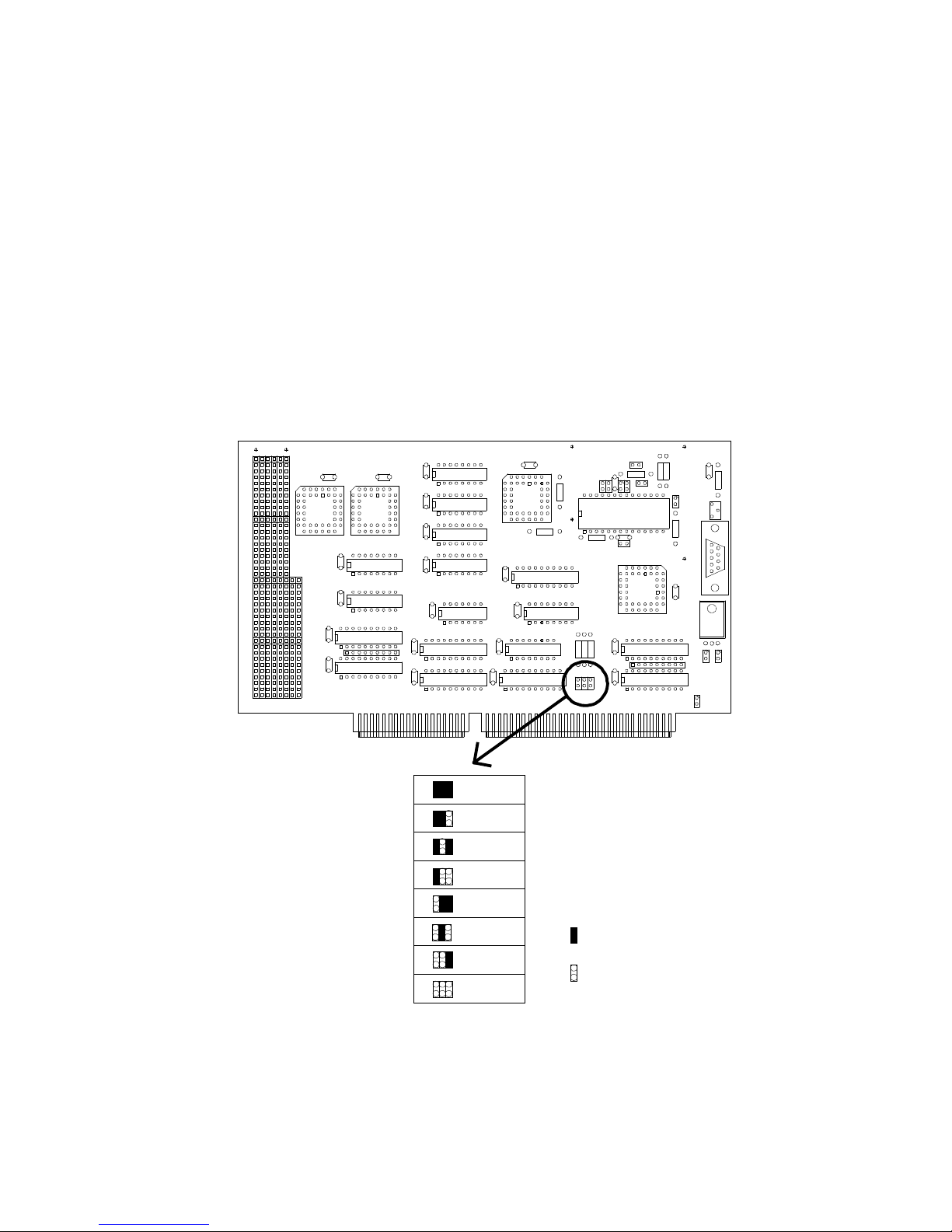
Before inserting the Accumulating Framegrabber in your PC, please check the jumper
settings for selecting the base address of the board. Refer to fig. 1 for determining the
correct settings.
Note: The default setting for the base address is 240 (hexadecimal). Do not change this setting unless
you encounter a bus conflict with some other board in your PC. We chose this address because it showed
a very low probability of interfering with other cards.
The Accumulating Framegrabber uses only 8 consecutive addresses in the I/O space of
your PC and NO interrupts or DMA channels. Please check also that you really insert the
200
240
280
2c0
300
340
380
3c0
default setting
jumper
no jumper
Fig. 1: Location of the base address selection jumpers
Page 5

5
Accumulating Framegrabber in a 16-bit slot. It won´t work in an 8bit slot.
•
Mount the Handmonitor on the Readout Unit (please refer to the manual of the Readout
Unit if you have problems).
•
Make sure that the Handmonitor is switched off. Start with a gain setting of ´2´ on the
Handmonitor (For scintillators with low light output use gain setting ´3´).
•
Connect the Readout Unit to the inserted Accumulating Framegrabber via the supplied
special video cable. Secure the cable with the fastening screws on the connectors.
•
Switch on your PC if you haven´t done so already. Hot-plugging of the Readout Unit
should usually be no problem unless you have an exceptionally weak power supply in
your PC.
•
Turn on the power switch on the Readout Unit. The power indicator LED on the Readout
Unit should be on now.
•
Try out the software on the supplied disks.
•
To adjust the focus of the CCD camera carefully turn the focus ring on the lens. For this,
open the camera housing first with the 3 screws on each side. Check your adjustment with
the program ´AFG.EXE´ or with a TV monitor connected to the Readout Unit. Please
check afterwards that the aperture setting wasn´t changed. The aperture should always be
set to ´open´ (i.e. f=1.3 or f=1.4, depending on lens type).
If you are in doubt, please contact us!
Page 6
6
CCD C
AMERA SETUP
In normal operation, the settings of the camera do not need to be changed. If you have certain
applications that absolutely require changes in the standard settings, we give here a short
description how to modify the camera setup. Please refer also to the manual of the Hitachi
KP-M1 camera for the following section.
External Controls:
•
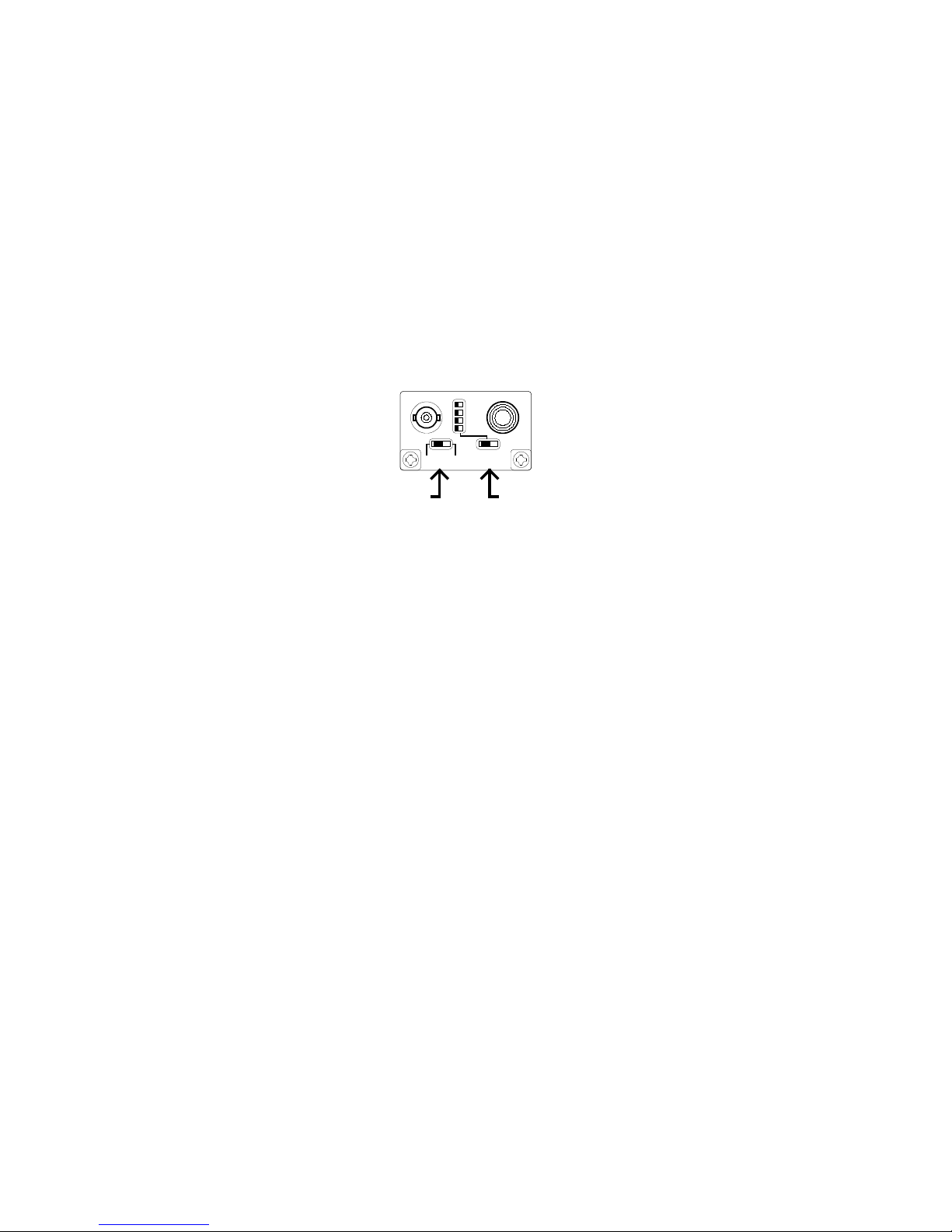
Remove the 6 screws that hold the cover of the Readout Unit and look at the panel at
the rear side of the CCD camera (see fig.2).
•
The ´field/frame´ switch should be set to the ´frame´ position
(Users of the Realtime Centroiding Processor should set this switch to the ´field´
position to avoid double-counting of neutrons due to the overlapping of frames in the
´frame´ mode. ´Frame´ mode, on the other side, gives a higher resolution and higher
sensitivity. Overlapping frames are no subject for the Accumulating Framegrabber,
because here the frames are summed up anyway.)
•
The ´shutter´ switch should be set to the ´off´ position (unless you have a special
application that makes use of the shutter, of course).
•
Don´t care for the shutter speed select switch, it is ignored when the shutter is switched
off.
Internal Controls:
Changing the internal settings of the CCD camera should only be done by qualified
personnel and requires great care to avoid damage!
•
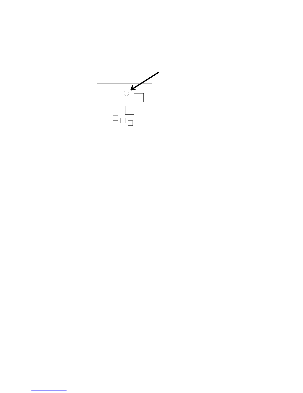
Opening the CCD camera reveals the video board that can be seen in fig. 3. The CCD
gain can be adjusted with RV301, the automatic gain control can be switched on with
SW301 and the gamma characteristic can be changed with switch SW302. Please note
the default settings before changing anything!
Shutter
On/Off Switch
VIDEO OUT DC IN/SYNC
FIELD FRAME
OFF ON
SHUTTER
Field/Frame
Switch
Fig. 2: Panel of the CCD camera inside the Readout Unit
Page 7
7
rear side
lens side
CCD video board
CCD Gain
adjustment
(RV301)
Fig. 3: Gain adjustment potentiometer inside the CCD camera of the Readout Unit
Page 8
8
F
INE-ADJUSTMENT PROCEDURES
:
This section applies only if you are doubtful about the current settings of your detection
system or if you use a non-standard scintillator with different light output from the standard
scintillator.
•
There are 4 different adjustment locations that determine the overall gain of the
detection system:
1. The gain setting of the Handmonitor.
2. The aperture setting of the lens.
3. The gain setting of the CCD camera (see fig. 3).
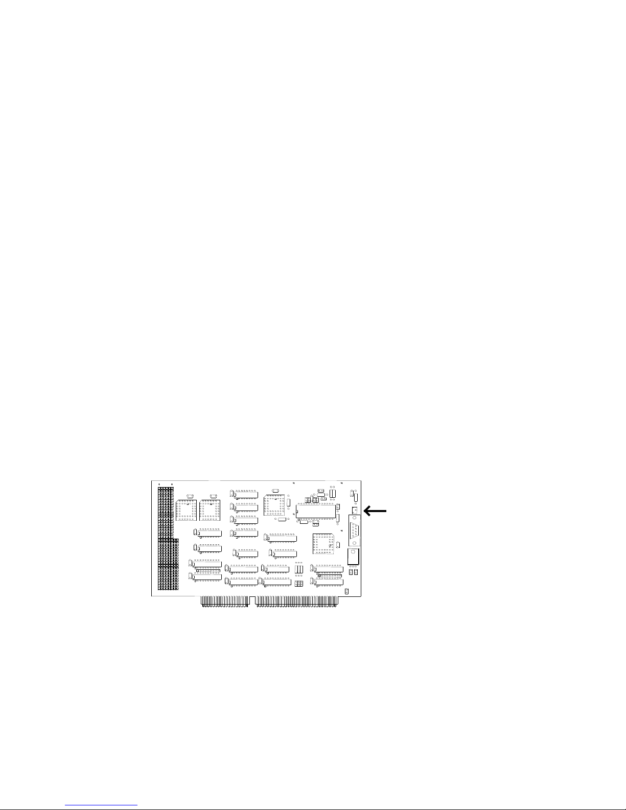
4. The gain setting of the analog-to-digital converter on the Accumulating
Framegrabber (see fig. 4).
•
Keep in mind that you should optimize for:
1. Best signal-to-noise ratio.
2. Highest dynamic range.
3. Lowest nonlinearities.
4. Highest spatial resolution.
I. If you are primarily using the Accumulating Framegrabber without discrimination and
without further determining the locations of the scintillation events, consider the
following:
That means that you should use a high gain on the image intensifier, because the signal-to
noise-ratio of the image intensifier is only weakly dependent on the gain. The aperture of
the lens should be large (i.e. you should use a low f-number). To adjust the gain of the
ADC Gain
adjustment
Fig. 4: Location of the ADC gain adjustment potentiometer
Page 9

9
CCD and ADC, you should first try to crank up the gain of the ADC, because this avoids
opening the CCD camera. If this still isn´t enough, turn back the gain of the ADC to its
former setting (which means that full range of the ADC corresponds to a 1 V p-p video
signal) and then crank up the gain of the CCD until you get enough signal.
Keep in mind that high gains of the image intensifier always run the risk of saturating the
image intensifier, leading to a drastic decrease of the linearity of the detector. This
saruration further leads to a lower spatial resolution because of the broadening of the
scintillation events on the intensifier screen when operating in the saturated region.
Depending on your experimental requirements you may then have to use a lower gain of
the intensifier and a higher gain of the CCD camera, at the expense of a somewhat higher
noise level.
II. If you are using the system mainly with discriminator and further data processing for
determination of the locations of the scintillation events, consider the following:
Using the technique of discrimination and further processing of the data needs
scintillation signals that are well above noise in each frame. The standard neutron
scintillator NE426 fulfills this requirement.
Use the standard gain setting of the CCD (as it was set when it was delivered), open the
aperture of the lens (set it to f=1.3 or f=1.4, depending on lens type), turn the ADC
adjustment potentiometer to the center position and try a gain setting of ´2´ on the
Handmonitor.
Expose the detector to a low neutron flux (some thousand neutrons per second, evenly
spread on the whole detector area), using the software that came with the Accumulating
Framegrabber (´afg.exe´ : please refer to the manual for this software). Use a ´Frames´
parameter of zero. Now you should see several dozens of neutrons per image. Choose an
appropriate color palette. Set the offset to the lowest possible value and the intensity
scaling to 1. Now change the gain of the ADC until a few percent of the neutrons reach
the saturation value.
H
ARDWARE DESCRIPTION
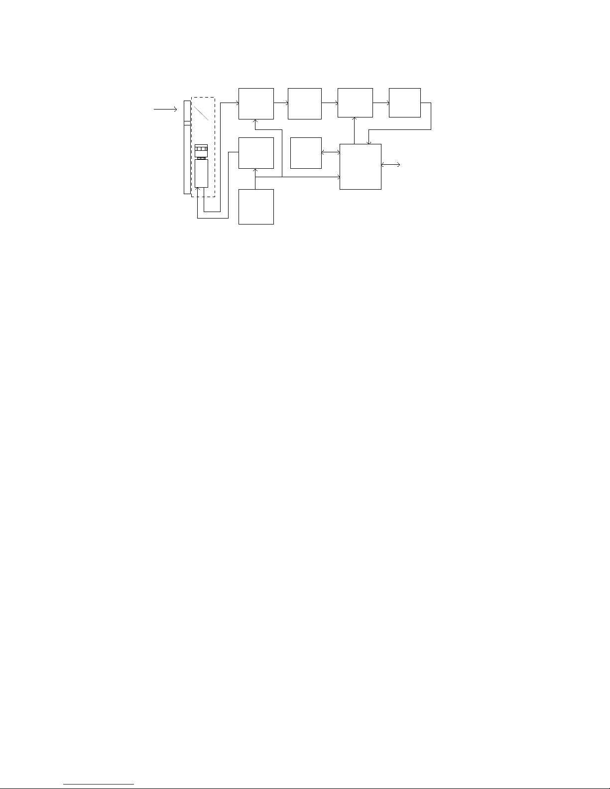
The block diagram of the Accumulating Framegrabber can be seen in fig. 5. There are
essentially 3 blocks that are accessible by the user: the discriminator, the frame counter and
the FiFo.
Page 10
10
For a demonstration of the workings of the Accumulating Framegrabber, let us look at a
simple demonstration program that reads in the frame buffer and shows it on the video screen:
/* AFGTEST.C:
This program reads the ND&M Accumulating Framegrabber
and displays the frame buffer on a 1024*768 pixel screen.
Compile this program with GNU C 2.6.0 with the
command: "gcc afgtest.c -o afgtest -O3 -lgrx -lpc" and run it
with: "go32 afgtest"
*/
#include <grx.h>
#include <time.h>
void getframe(void);
void erasefifo(void);
/* Frames per integration period = 2^(FRAMEXP+1) */
#define FRAMEXP 0
#define FGRW 0x240
#define FGINT 0x242
#define FGRES 0x244
#define FGTHR 0x246
#define VBASE 0xd0000000L
int mx, my;
main()
{
int i;
GrSetMode(GR_width_height_color_graphics,
1024,768,256); /* Set graphics mode */
for(i=0;i<255;i++)
GrSetColor(i,i,i,i); /* Set palette */
while(!kbhit()) { /* Read in AFG until key pressed */
inportw(FGRW);
inportw(FGRW);
outportw(FGRW,0);
outportw(FGRW,0); /* Make sure that the FiFo is */
/* resetable */
n-beam
ADC +
clamp
8 bit
Genlock
generator
Clock-
generator
14.3 MHz
Discrimi-
nator
Adder
A
B
A+B
FiFo
256k*16
Frame
counter
Control +
Bus
Interface
Logic
PC/AT-Bus
(ISA-Bus)
Handmonitor
Mirror
Camera
Readout box
Fig. 5: Block diagram of the Accumulating Framegrabber
Page 11

11
outportw(FGRES,0); /* Reset the FiFo */
erasefifo(); /* Erase the FiFo */
getframe(); /* Read in FiFo and display it */
}
GrSetMode(GR_default_text); /* Restore old graphics mode */
}
void getframe()
{
unsigned short i, j;
static unsigned short iline[512];
char *p;
p=(char *)VBASE; /* Set base address of SVGA card */
outportw(FGTHR,0); /* Set discriminator level */
outportw(FGINT, FRAMEXP); /* Set number of frames and */
/* start integration period */
while(!(inportw(FGINT) & 1)) ; /* Wait until bit 0 of AFGINT */
/* goes to 1 ... */
while(inportw(FGINT) & 1) ; /* ... and to zero again: */
/* Now the integration is over */
for(j=0;j<160;j++)
outportw(FGRW, 0);
inportw(FGRW);
inportw(FGRW);
inportw(FGRES); /* Make sure that the Fifo captures */
/* also the last data words */
for(j=0;j<256;j++) { /* Read in the even lines */
inportsw(FGRW, iline, 512);
for(i=0;i<512;i++)
*(p++)=(unsigned char)(iline[i] >> (FRAMEXP+1) );
p+=1536;
}
p=(char *)VBASE + 1024;
for(j=0;j<256;j++) { /* Read in the odd lines */
inportsw(FGRW, iline, 512);
for(i=0;i<512;i++)
*(p++)=(unsigned char)(iline[i] >> (FRAMEXP+1) );
p+=1536;
}
} /* That´s it */
void erasefifo()
{
int i;
unsigned short buf[512];
for(i=0;i<512;i++) /* Load a buffer for faster output */
buf[i]=0;
for(i=0;i<513;i++)
outportsw(FGRW, buf, 512); /* Write out buffer to Fifo */
}
From the program listing you can see that there are 4 addresses that are relevant for
programming (a base address of 240 (hexadecimal) is assumed here):
Page 12

12
FGRW (240):
An I/O read instruction on this address gets a new 16-bit data value from the FiFo. Use only
16-bit accesses to read from this port. The internal read address pointer inside the FiFo is
automatically incremented, so you can make use of the very efficient string I/O instructions of
the 80386 and higher (REP INSW). The contents of the FiFo remain stored, so you can read
them as many times as you want.
An I/O write instruction stores data in the FiFo. The internal write address pointer inside the
FiFo is automatically incremented, so you can make use of the efficient string I/O instructions
of the 80386 and higher (REP OUTSW).
FGINT (242):
A write on this address loads the frame counter with the lower 3 bits of the data word and
starts an integration period. The integration time can thus have 8 different values:
0 = 2 x 40 ms = 80 ms
1 = 4 x 40 ms = 160 ms
2 = 8 x 40 ms = 320 ms
3 = 16 x 40 ms = 640 ms
4 = 32 x 40 ms = 1280 ms
5 = 64 x 40 ms = 2560 ms
6 = 128 x 40 ms = 5120 ms
7 = 256 x 40 ms = 10240 ms
A read on this address retrieves the status of the Accumulating Framegrabber in bit 0 of the
data word. Right after writing to FGINT, this bit 0 goes to zero. Shortly after this, the bit 0
goes to zero, thus indicating the begin of the integration time. At the end of the integration
time, bit 0 goes to zero again.
FGRES (244):
A write to this address resets the write address pointer of the FiFo, a read on this address
resets the read address pointer of the FiFo. Between two consecutive reset commands there
should be a minimum of 2 read or write commands, respectively.
FGTHR (246):
A write to this address sets the discriminator threshold. The allowed values range from 0 to
255.
Page 13

13
C
ONNECTOR PIN ASSIGNMENT
Connector Type: 9-pin SUB-D
PIN # Function
1 GND Handmonitor
2 GND Camera
3 reserved
4 +12V Camera
5 +12V Handmonitor
6 Sync out
7 Video in
8,9 reserved
T
ECHNICAL SPECIFICATIONS
ADC resolution: 8 bits
# of digitized pixels: 512 x 512
Pixel clock: 14.318 MHz
Frame Buffer: 512 kByte
Discriminator: 8 bits, programmable
Signal system: CCIR system
Horizontal scan frequency: 15625 Hz
Vertical scan frequency: 50 Hz
Video input: 1.0 V p-p, 75 Ohms, unbalanced
Sync output: 1 V p-p, negative
Board type: 16 bit, ISA
operating conditions: 20..40 °C, 0..40 % rel. humidity
Ser. No.: _____________________________
 Loading...